simulation of dfig and fsig windfarms in matlab...
TRANSCRIPT

LUND UNIVERSITY
PO Box 117221 00 Lund+46 46-222 00 00
Simulation of DFIG and FSIG windfarms in MATLAB SimPowerSystems
Sulla, Francesco
2009
Link to publication
Citation for published version (APA):Sulla, F. (2009). Simulation of DFIG and FSIG windfarms in MATLAB SimPowerSystems. Division of IndustrialElectrical Engineering and Automation, Faculty of Engineering, Lund University.
General rightsCopyright and moral rights for the publications made accessible in the public portal are retained by the authorsand/or other copyright owners and it is a condition of accessing publications that users recognise and abide by thelegal requirements associated with these rights.
• Users may download and print one copy of any publication from the public portal for the purpose of private studyor research. • You may not further distribute the material or use it for any profit-making activity or commercial gain • You may freely distribute the URL identifying the publication in the public portalTake down policyIf you believe that this document breaches copyright please contact us providing details, and we will removeaccess to the work immediately and investigate your claim.

Indust
rial E
lectr
ical Engin
eering a
nd A
uto
mation
CODEN:LUTEDX/(TEIE-7235)/1-007/(2009)
Simulation of DFIG and FSIG
wind farms in
MATLAB SimPowerSystems
Francesco Sulla
Division of Industrial Electrical Engineering and Automation
Lund University

Simulation of DFIG and FSIG windfarms in MATLAB SimPowerSystems
1. Introduction
In this report, results from simulations of Doubly Fed Induction Generators (DFIG) and Fix Speed Induction Generators (FSIG) wind farms performed in MATLAB SimPowerSystems [1] are presented. Many issues arise when simulating such wind turbines. In reference [2], it is shown how for ex. the order of the induction machine used in the simulation, the double mass model of the wind turbine, the type of simulation (rms or instantaneous values), all have a more or less determinant effect on the results of the simulations. The message from the reference is that if accurate simulations results are necessary, a very detailed model is required. Here however, these modeling issues are not considered and existing models have been used with some modifications (crowbar protection). The attention is focused in understanding the different behavior of DFIG and FSIG Low Voltage Ride Through (LVRT) after a tree-phase fault in the system. A crowbar system for the DFIG will be designed following [2]. Section 2 of the report describes the models used in the simulations. The third and fourth sections present the results from simulations of LVRT of DFIG and FSIG wind farms, respectively. Some conclusions are presented in the last section.
2. Description of Simulation Models
The same induction machine and wind turbine models have been used for modeling the DFIG and the FSIG wind farms. Therefore only the DFIG wind farm model will be described here.
Wind turbine modelThe wind turbine model is a lumped mass one, i.e. it does not model the double mass phenomenon. The turbine is a pitch controlled one. The pitch angle β control signal comes from the DFIG control block. The Cp coefficient is calculated through a look-up table and the output of the wind turbine block is the torque on the induction generator axis. The pitch angle β is only varied to limit the over-speed of the generator. The wind speed is considered constant and equal to 10 m/s during the simulations.
Induction Machine modelThe model of the IG is an instantaneous values full order one, i.e. fifth order with the derivative of the stator fluxes included. This is the best choice to accurately simulate transients in the power systems when the electrical dynamics of the IG is of primary interest. Saturation is not included in the model, but reference [2] states that this only leads to small negligible errors in the prediction of the maximum short-circuit current and LVRT behavior (this is a credible assumption, since it is primarily the series stator and rotor inductances that determine the short-circuit current, and these inductances saturate only slightly because the leakage flux goes through the air). The values of the IG parameters have been chosen as in [2] and are reported in Table 1. The DFIG wind farm is composed of 6 aggregated units of 1.5MW each, while the FSIG wind farm is composed of only 2 units of 1.5 MW each.

Parameter ValuePnom 9 or 3 (MW)
cos(phi) 0.9Rs 0.01Rr 0.01Xs 0.12Xr 0.2
Table 1. Induction generator parameters for DFIG (9MW) and FSIG (3MW) windfarms
Grid Side ConverterThe GSC is modeled using a universal bridge model with IGBTs connected to the IG terminals through a series RL filter. The control of the GSC aims at keeping the DC-link capacitor voltage constant at nominal value. It does not contribute to grid voltage regulation or reactive power injection (Iq = 0). This is a limitation, since reactive power injection through the GSC could be used to improve LVRT helping in a faster voltage recovery. The converter maximum power is half the IG rated power. The grid voltage angle is calculated with a PLL. The switching frequency for both the GSC and the RSC is 1620 Hz. The nominal DC-link capacitor voltage is 1200V.
Rotor Side ConverterThe rotor side converter is modeled using a universal bridge model with IGBTs connected to the IG rotor windings. The RSC controls the active power delivered by the DFIG, by determining a torque reference (following a Power-Speed curve). This torque reference is used along with a flux estimate to determine the reference rotor current Idr. The RSC model (in the original model controlled to not deliver any reactive power) has been modified so to support the grid voltage with reactive power injection. The reference for the reactive power is determined through a PI controller by measuring the grid voltage and comparing it with a reference.
CrowbarThe SimPowerSystems DFIG model does not include a crowbar protection. This has therefore been added, with some simplifications. The crowbar is made up of a symmetric three phase y-connected resistance. It is connected to the rotor through a controllable breaker. This is not the real case (in reality, the crowbar may be made up of one resistance fed through a switched rectifier bridge), but it may be sufficient for us to assess the overall impact of a crowbar protection on the LVRT. The breaker is normally open, but it is closed short-circuiting the rotor through the resistance if either the rotor current or the DC-link capacitor voltage become too high. At the same time the switching of the RSC is stopped. The value of the crowbar resistance is chosen according to [2] as 20 times the rotor resistance. The choice of the crowbar resistance is important because, as we will see, it detemines how much reactive power the DFIG will draw while the crowbar is inserted.The crowbar can be disconnected and the RSC reinserted either after a fix time or when the rotor current and DC-link voltage return well within their normal operating range.
Network ModelThe used network model is shown below. The wind farm is connected to a 25 kV network, via a 25/0.575 kV transformer. The transformer is rated 12 MVA and its impedance is equal to 5%. A

resistive load is connected at the wind farm. A high pass capacitor filter is connected at the DFIG wind farm for absorbing high current harmonics, generated by the switching in the converters. The DFIG wind farm is then connected to the 120 kV network through a 30 km 25 kV line and a 120/25 kV transformer. The positive sequence parameters data for the 25 kV line are reported in Table 2. We are not interested in its zero sequence data, since we do not simulate earth-faults. Three-phase faults are simulated at t=500 ms and disconnected at t = 650 ms. The location of the fault is shown in Figure 1, bus B25.
R 0.115 Ω/kmL 0.001 H/kmC 11.3 nF/km
Table 2. 25 kV line parameters data. The line is 30 km long.
Figure 1. Network model schematic
3. Results from DFIG LVRT Simulations
The simulation of the LVRT of a DFIG wind farm has been performed using the described crowbar protection. The results are shown below. Before the fault, the DFIG windfarm was in steady state feeding 50% of its rated power and almost no reactive power. When the fault occurs, the crowbar protection is triggered, protecting the RSC which stops switching. The rotor current in the crowbar and the rotor windings decays and the DC-link voltage ( the 5th, unnamed variable in Figure 3) increases slightly while the crowbar is connected. Notice that the crowbar disconnects and the RSC starts switching while the fault is still active, at about 70 ms after the fault. This is important since it allows the DFIG to feed reactive power (about 0.3 pu) into the network, increasing the voltage. This of course may have a positive effect for the voltage stability of the system.The rotor current in the DFIG windings (Iabc_rot_IG) decreases, while the RSC current (I_rot) is zero when the crowbar is active. The RSC voltage is then the voltage over the crowbar.The DC-link capacitor voltage (the 5th, unnamed variable in Figure 3) does not increase much just after the fault. However, its increase is very high (2 pu) when the fault is disconnected at 650 ms, even though the crowbar is correctly reinserted to limit the RSC current. This increase, as can be seen, is due to the fact that the DFIG absorbs active power just after the fault is disconnected. This clearly indicates the need for a chopper to be connected across the DC-link capacitor to limit its voltage.Finally notice that when the fault is disconnected, the DFIG absorbs reactive power, thus decreasing the voltage in the network. This is due to the fact that, being the crowbar still connected for a long time (because of the high DC-link voltage), the DFIG is actually a FSIG accelerating and thus drawing lot of

reactive power. This bad behavior of the DFIG would be attenuated (and probably) eliminated if a chopper was used, since then the crowbar would disconnect in shorter time (when the DC-link capacitor voltage would decrease within acceptable limits) allowing the RSC to re-take control of the reactive power.The crowbar protection however seems to perform well in protecting the RSC. It also seems that the use of a chopper would allow the considered DFIG to ride through the three-phase fault.
Fig. 2. DFIG LVRT at a three-phase fault.

Fig. 3. DFIG LVRT at a three-phase fault.
4. Results from FSIG LVRT Simulations
The behavior of a FSIG during a fault has also been analyzed. The IG has same pu data as the DFIG generator, but the wind farm is now rated 3 MW. It has been connected at the same location of the DFIG. Results from a three-phase short circuit are shown below. A capacitor bank rated 20% of the IG rated power is connected at its terminals, and the reactive power shown below is inclusive of the capacitor contribution. Before the fault, the IG and capacitor actually deliver reactive power to the grid. This may not be realistic, but should not change the meaning of the analysis during the fault. It is observed that the IG feeds through all the fault duration a current higher than 2 pu. Also after the fault disconnection, the current remains higher than 1 pu for a while because of the large amount of reactive power absorbed by the accelerating IG. At a certain time after the short-circuit, the overcurrent protection of the generator may disconnect it from the network. The stator current decays faster in the DFIG case because of the extra rotor resistance of the crowbar. Moreover, these high currents in turn cause a voltage drop in the network at about 0.8 pu after the fault disconnection before the voltage is re-established. In a worst case scenario, for ex if the pre-fault mechanical power would be higher (causing higher overspeeding), the reactive power demand after the fault may cause a voltage collapse phenomenon, with stator currents even higher than the ones shown in this simulation. This is a main reason why FSIG without proper reactive power aid (e.g. a statcom)
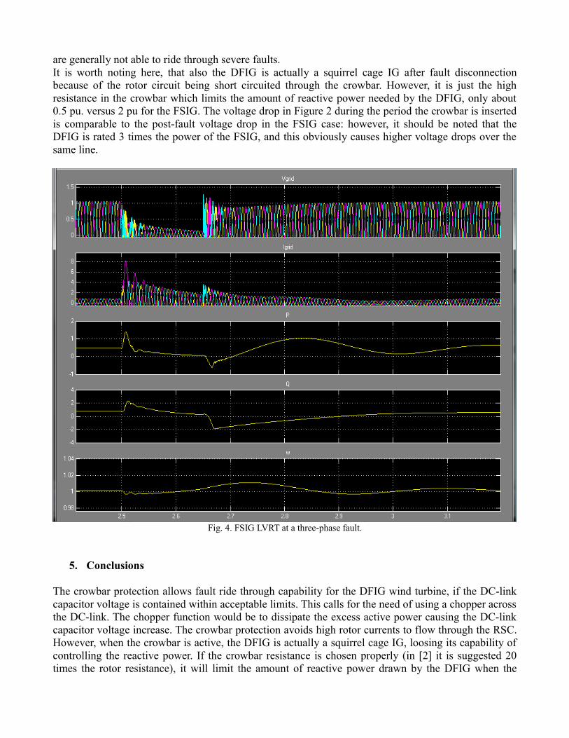
are generally not able to ride through severe faults. It is worth noting here, that also the DFIG is actually a squirrel cage IG after fault disconnection because of the rotor circuit being short circuited through the crowbar. However, it is just the high resistance in the crowbar which limits the amount of reactive power needed by the DFIG, only about 0.5 pu. versus 2 pu for the FSIG. The voltage drop in Figure 2 during the period the crowbar is inserted is comparable to the post-fault voltage drop in the FSIG case: however, it should be noted that the DFIG is rated 3 times the power of the FSIG, and this obviously causes higher voltage drops over the same line.
Fig. 4. FSIG LVRT at a three-phase fault.
5. Conclusions
The crowbar protection allows fault ride through capability for the DFIG wind turbine, if the DC-link capacitor voltage is contained within acceptable limits. This calls for the need of using a chopper across the DC-link. The chopper function would be to dissipate the excess active power causing the DC-link capacitor voltage increase. The crowbar protection avoids high rotor currents to flow through the RSC. However, when the crowbar is active, the DFIG is actually a squirrel cage IG, loosing its capability of controlling the reactive power. If the crowbar resistance is chosen properly (in [2] it is suggested 20 times the rotor resistance), it will limit the amount of reactive power drawn by the DFIG when the

crowbar is active.The FSIG has no means to control the reactive power, unless it is not provided with a dedicated reactive power supply unit, e.g. a statcom. This fact makes it difficult for the FSIG to ride through severe faults, since this will result in an acceleration of the FSIG. When accelerated, the FSIG draws large amount of reactive power and a voltage collapse may be the consequence. Even if the voltage does not decrease (for ex. because the network is strong), it may still be necessary to disconnect the FSIG for overcurrent, as in the case simulated in this report.
References
[1] MATLAB SimPowerSystems User's Guide, Version 4.6 (R2008a), http://www.mathworks.com/access/helpdesk/help/toolbox/physmod/powersys/
[2] Akhmatov V., “Induction Generators for Wind Power”, Multi-Science Publishing Company, Ltd., 2005.