simulation of lamb wave reflections at plate edges using ... · pdf filesimulation of lamb...
TRANSCRIPT
Accepted Manuscript
Simulation of Lamb wave reflections at plate edges using the semi-analytical
finite element method
Z.A.B. Ahmad, U. Gabbert
PII: S0041-624X(12)00105-9
DOI: http://dx.doi.org/10.1016/j.ultras.2012.05.008
Reference: ULTRAS 4420
To appear in: Ultrasonics
Received Date: 23 November 2011
Revised Date: 21 May 2012
Accepted Date: 22 May 2012
Please cite this article as: Z.A.B. Ahmad, U. Gabbert, Simulation of Lamb wave reflections at plate edges using the
semi-analytical finite element method, Ultrasonics (2012), doi: http://dx.doi.org/10.1016/j.ultras.2012.05.008
This is a PDF file of an unedited manuscript that has been accepted for publication. As a service to our customers
we are providing this early version of the manuscript. The manuscript will undergo copyediting, typesetting, and
review of the resulting proof before it is published in its final form. Please note that during the production process
errors may be discovered which could affect the content, and all legal disclaimers that apply to the journal pertain.
Simulation of Lamb wave reflections at plate edges usingthe semi-analytical finite element method
Z.A.B. Ahmada,∗, U. Gabbertb
aJabatan Dinamik Sistem dan Kawalan, Fakulti Kejuruteraan Mekanikal, UniversitiTeknologi Malaysia, 81310 Skudai, Malaysia.
bLehrstuhl Numerische Mechanik, Fakultat fur Maschinenbau,Otto-von-Guericke-Universitat Magdeburg, Universitatsplatz 2, 39106 Magdeburg,
Germany.
Abstract
In typical Lamb wave simulation practices, effects of plate edge reflectionsare often not considered in order to simplify the wave signal interpreta-tions. Methods that are based on infinite plates such as the semi-analyticalfinite element method is effective in simulating Lamb waves as it excludesthe effect of plate edges. However, the inclusion of plate edges in a finiteplate could render this method inapplicable, especially for transient responsesimulations. Here, by applying the ratio of Lamb mode reflections at plateedges, and representing the reflection at plate edges using infinite plate solu-tions, the semi-analytical finite element method can be applied for transientresponse simulation, even when the plate is no longer infinite.
Keywords: SAFE method, Lamb wave, edge reflection, transient response,finite plate
1. Introduction
Lamb wave can propagate in relatively long distances in plate-like struc-tures and has high sensitivity to small damages. These make it suitable forstructural health monitoring applications. However, its sensitivity also ex-tends to plate edges. Thus, the effect of edges need to be taken into accountin applying Lamb waves for such systems.
∗Corresponding authorEmail addresses: [email protected] (Z.A.B. Ahmad), [email protected] (U.
Gabbert)
Preprint submitted to Ultrasonics June 4, 2012
To date, the finite element method (FEM) is the most robust tool tosimulate Lamb wave propagations. However, the computational requirementis still very large. One of the method that can reduce this requirement isthe semi-analytical finite element (SAFE) method. In the SAFE method,discretization is made only to the plate cross section while in the wavepropagation direction, exponential function is used.
The SAFE method has been used to obtain Lamb wave dispersion curvesfor both isotropic and composite plates [1, 2, 3]. The effect of plate edges onLamb wave reflections is studied by coupling SAFE with FEM [4] or bound-ary element method (BEM) [5]. In these approaches, the SAFE method isused to model the infinite plate region while the FEM/BEM is used to modelthe complex plate edges and boundary conditions. This coupling approachhas been extended in [6, 7] to study the effect of obstacles at the middleof an infinite plate. The SAFE method has also been used for transient re-sponse analysis in infinite waveguides and plates [8, 9, 10]. In this analysis,the calculation is made in frequency domain. Inverse fast Fourier transform(inverse FFT) is then used to obtain the solution back in time domain.
For Lamb wave actuator simulations, having an infinite plate in theSAFE method is an advantage as the plate edge reflection is already beingremoved. Thus, there are no edge reflections in the obtained Lamb wavesignals. On the other hand in the FEM, such infinite boundaries wouldrequire special infinite elements to avoid the Lamb wave reflection from theplate edges [11]. A simpler solution in the FEM would be to model theplate as large as possible to avoid edge reflection. But this results in ahigher computational costs. Another approach is by using elements withincreasing damping at the plate edges to avoid reflections [12]. However,when the effect of plate edge reflections are required i.e. for comparisonwith FEM simulations or experimental results, it is not easy to include theseboundary effect in the SAFE method. Here, a method is presented allowingthe effect of plate edge reflections to be included in the SAFE transientresponse simulation.
2. Approximation for plate edge reflection
In our proposed method, the SAFE method is used to calculate thedispersion relation required i.e wavenumbers and mode shapes for each cir-cular frequency. By using these results, transient response calculations as in[8, 9, 10] are made giving the transient response solution for infinite plates.Through the coupled SAFE-FE method [4], the ratio of modes reflected bythe plate edge is obtained. Then, by applying the ratio of reflected modes
2
and by representing reflected waves as additional infinite plate solutions, thetransient response for plate with edges is simulated.
The proposed approach begins with the SAFE method governing equa-tion for the plate without external force[
k2K3 + kK2 + K1 − ω2M]U = 0 (1)
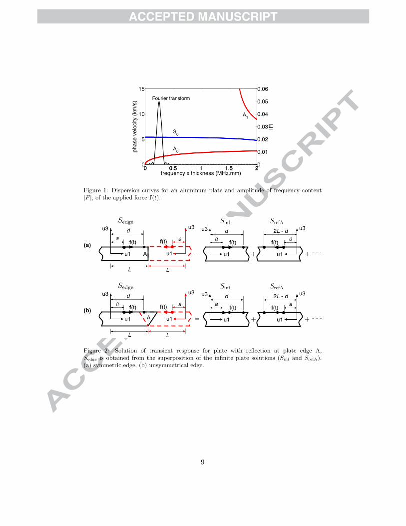
where K1, K2 and K3 are the global stiffness matrices and M is the globalmass matrix. Solving this eigenvalue problem gives the relationship betweenwavenumber k (including mode shape U) and circular frequency ω. Thisrelationship can be used to plot the dispersion curves as shown in Figure 1for an aluminum plate. Equation (1) can be rewritten as
[A + kB]Ψ = 0;Ψ ={
UkU
};A =
[K1 − ω2M 0
0 −K3
];B =
[K2 K3
K3 0
].
(2)In the coupled SAFE-FE method, infinite plate region is modelled using
SAFE while the plate edge is modelled using FEM. The total energy in thefinite element (FE) region must be zero. Thus,
δqTSq− δqTBPB = 0, (3)
where
S = KFE − ω2MFE =[SII SIB
SBI SBB
], (4)
qT =[qT
I qTB
]. (5)
Matrix KFE and MFE are the global stiffness and mass matrices of the finiteelement region. Subscript I and B and overbar denote nodes inside the FEregion, nodes at the boundary and complex conjugate, respectively. q andP are the nodal displacement and force vectors, respectively. For plateedge reflections, the nodal displacement and force vectors at the boundarybetween FE and SAFE regions are given by
qB = q(in)B + q(r)
B PB = P(in)B + P(r)
B (6)
where superscript (in) and (r) denote incident and reflected waves, respec-tively. A single Lamb mode incident propagation is considered. The nodaldisplacement and force vectors can be approximated by the wave functionexpansion of a finite number of modes. After substituting the wave functionexpansion into the nodal displacement and the force vectors terms, the ratio
3
between the reflected modes due to an incident mode (reflection coefficient)can be obtained [4].
In the 2D transient response analysis, the force term is added to theequation (2) ([8, 9, 10]) giving
[A + kB]Ψ = F, F ={f0
}(7)
where f is the vector of the nodal external force at the circular frequencyω. The solution of the force vibration problem is found by applying theFourier transform to equation (7) to obtain an equation and solution in thewavenumber domain, and then applying the inverse Fourier transform toobtain the solution in the spatial domain. The point response for particularcircular frequencies is obtained from
u(x, z, ω, t) = −iN∑
r=1
[ψT
r Fψr
ψTr Bψr
](8)
where u is the displacement vector across the plate thickness for every x.Summation is made over N modes that correspond to the propagating anddecaying evanescant mode in x > 0 (excitation point is taken at x = 0).The displacement response can then be obtained by the sum of functions ufor each ω corresponding to values of f which are significant making use ofthe inverse Fourier transform. Solving equation (8) would give a transientresponse solution for an infinite plate.
Consider a transient response that counts for the reflection from plateedges represented by Sedge. This transient response can be approximated asa superposition of infinite plate solutions which consists of infinite plate so-lution Sinf (that represent only the infinite plate) and infinite plate solutionsSref (that represent each edge reflection). Sedge can be written as
Sedge = Sinf +n∑
i=1
Sref (9)
with n as the number of edge reflections. In this approach, the plate edgeis considered as a mirror which reflects back the incoming waves.
Consider a plate having a symmetrical edge shown in Figure 2(a) withan applied force f(t). Fixed vertical plate edge A is taken as example.The transient response of a point located at a distance b from the originis monitored. Waves will propagate to the right represented by the infiniteplate solution, Sinf. Reflections will occur when the waves reach edge A.
4
An infinite plate solution, SrefA which is a mirror image of the incidencewave at the plate edge is added to the Sinf, to account for the reflections.Direction of the positive u1 axis in SrefA is opposite to the incident wavesat the plate edge. SrefA has a wave propagation distance of 2L − b. Thisdistance is obtained by considering the distance of the wave travelling to themonitored point after being reflected by the plate edge. For unsymmetricalplate edge as in Figure 2(b), the propagation distance should not includethe edge region (i.e the 45◦ edge).
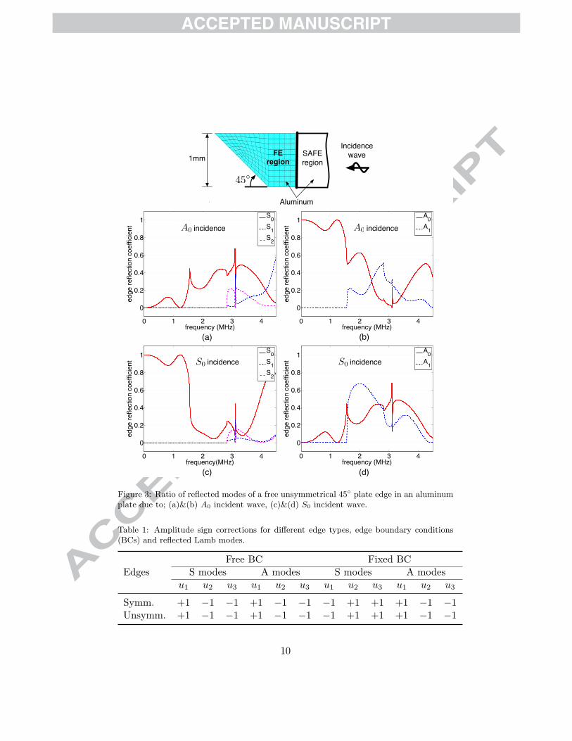
Alternatively, instead of changing the sign of the positive u1 axis, signof Sref amplitude can be changed accordingly depending on edge types andboundary conditions. In Table 1, sign corrections for symmetrical and un-symmetrical plate edges, and for free and fixed plate edges are given.
The magnitude of the Sref amplitude depends on the ratios of reflectedmodes at the plate edge (reflection coefficients). For symmetrical plateedges, no mode conversion occurs when the waves are reflected at the plateedges. However, for unsymmetrical plate edges, mode conversion always oc-curs due to plate edge reflections as shown in Figure 3. Whichever the case,ratios of reflected modes for both symmetric and unsymmetrical edges arefrequency depended.
The number of infinite plate solution representing the plate edge reflec-tion depends on the number of edge reflection considered. In a finite plate,this depends on the simulation time. With a longer simulation time, addi-tional edge reflections might need to be considered.
3. Numerical examples
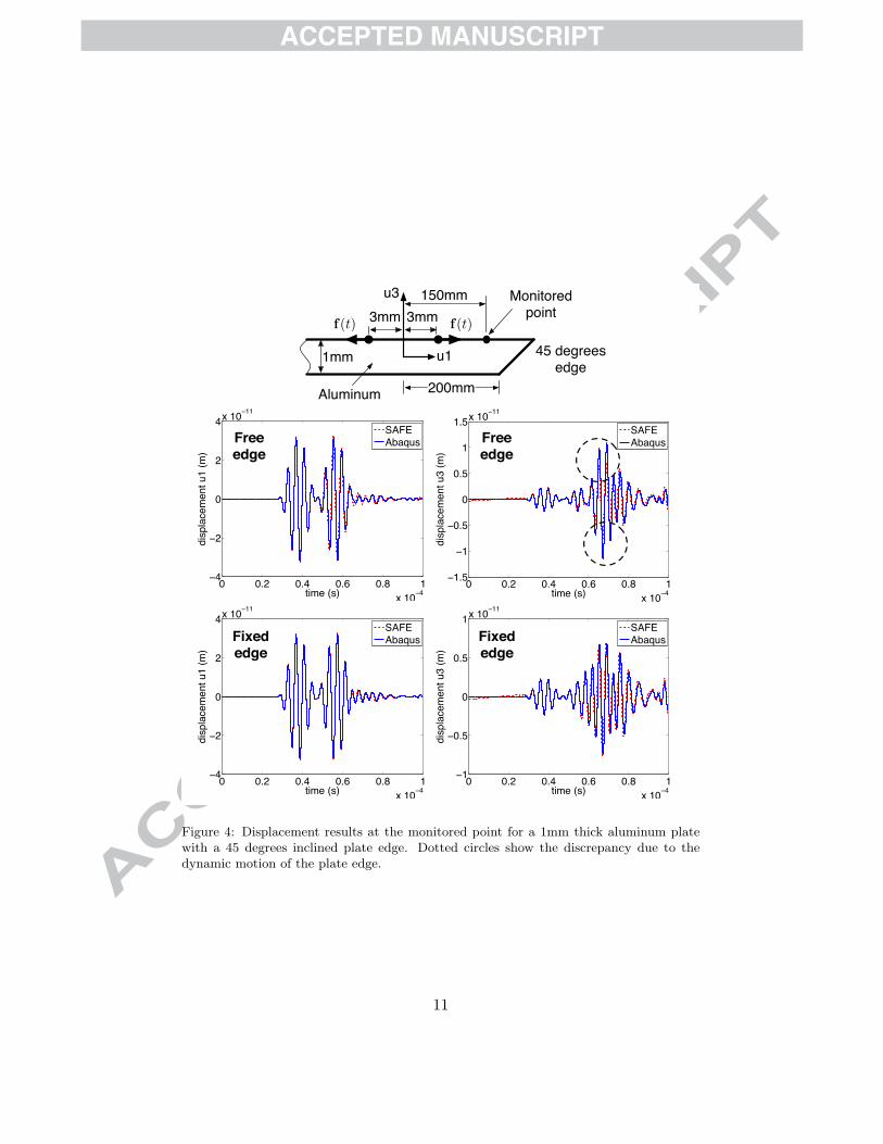
In following examples, transient response at a monitored point located150mm away from the origin in an aluminum plate is considered. The platehas a Young’s modulus of 70GPa, the density of 2700kg/m3, a Poisson ratioof 0.33, a length of 2L = 400mm and a thickness of 1mm. The materialdamping is neglected. A five cycles toneburst with Hann window and acenter frequency of 250kHz is taken as the applied force f(t). For a 1mmthick aluminum plate, only frequencies up to 500kHz need to be consideredas shown in the Fourier transform of this force in Figure 1, involving only S0
and A0 modes. The displacement results are compared with FEM solutionsobtained using Abaqus software. In Abaqus, plain strain elements, CPE4are used with 16 elements per 1mm. The simulation time is taken as 0.1ms.
Figure 3 shows an example of the amplitude ratios of reflected modesat a 45◦ plate edge in an aluminum plate for the S0 mode and the A0
mode incident waves. As the plate edge is unsymmetrical, mode conversions
5
always occur for both symmetrical and anti-symmetrical incidence waves.The same analysis can be made for other types of plate edges and bound-ary conditions. In general, the amplitude ratios and the type of reflectedmodes depend on the edge type, the boundary condition and the excitationfrequency considered.
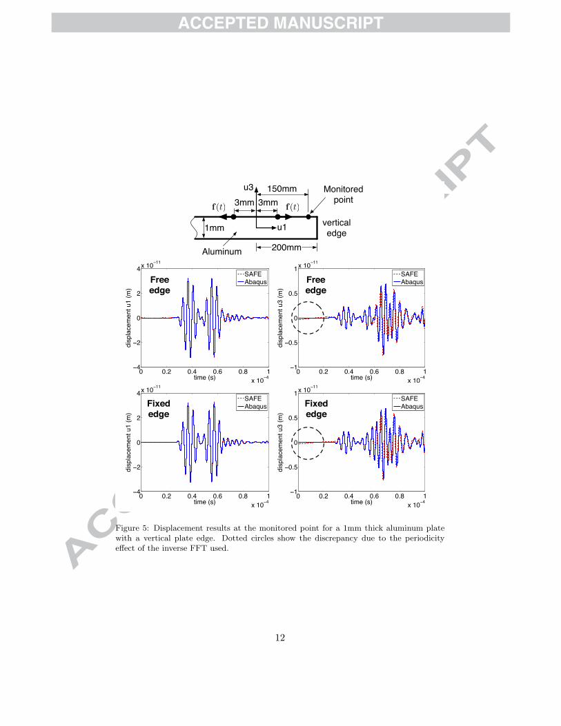
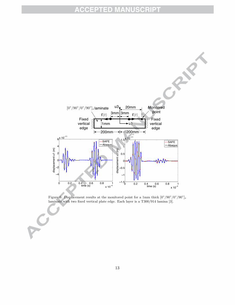
Figures 4 and 5 show comparison results for unsymmetrical and symmet-rical plate edges for free and fixed boundary conditions. For these examples,only one reflection is considered. Figure 6 shows the displacement resultsat the monitored point located at a distance of 20mm for a 1mm thick[0◦/90◦/0◦/90◦]s laminate. In this case, the waves are being reflected byboth fixed vertical plate edges within the simulation time of 0.1ms.
In all these examples, good agreements with Abaqus solutions are ob-tained. The transient response calculation in SAFE is done in frequencydomain. To obtain the solution in time domain, inverse fast Fourier trans-form (inverse FFT) has been used. Small discrepancies in all SAFE resultscan be explained by the wrap around effects [13] in the inverse FFT usedto calculate these displacement results. The inverse FFT transformation as-sumed that the wave displacements are periodic. Due to periodicity, solutionat the end should be equal to the solution at the beginning of the simulationtime. Therefore, when the displacement results at the end of the simulationtime are not zero, these results would pollute the displacement results atthe beginning of the simulation time (see Figure 5). This effect could bereduced by taking a simulation time that ensures zero displacements at theend of the simulation time for all the infinite plate solutions.
Another point worth mentioning is that the comparison results for fixededge reflections are better than the comparison results for free edge reflec-tions. This is due to the fact that the reflection coefficients calculated fromthe coupled SAFE-FE approach can not take into account the actual dy-namic motion of plate edges which is found especially at free edges (seeFigure 4). On the other hand, these edge dynamic motions are alreadybeing considered in FEM results.
4. Conclusion
The presented approach enables the SAFE method to be used for plateswith edges. For complex plate edges or frequency ranges that involve moremodes, ratio of each modes at each frequency considered need to be includedin the infinite plate solution to account for the edge reflection. The sameapproach should also be applicable for extending 3D Lamb wave simulationof infinite plate [14] to plate with edges. However, in 3D simulations, the
6
wavefront is not straight as in 2D cases. Furthermore, special considerationis also needed at corner points of the plate.
Acknowledgements Financial support of this work by Malaysian Ministryof Higher Education and by the German Research Foundation (GA 480/13-1)is gratefully acknowledged.
References
[1] S. Datta, A. Shah, R. Bratton, T. Chakraborty, Wave propagation inlaminated composite plates, Journal of Acoustical Society of America83(6) (1988) 2020–2026.
[2] W. Karunasena, A. Shah, S. Datta, Wave propagation in a multilay-ered laminated cross-ply composite plate, Transactions of the ASME58 (1991) 1028–1032.
[3] I. Bartoli, A. Marzani, F. di Scalea, E. Viola, Modeling wave propaga-tion in damped waveguides of arbitary cross-section, Journal of Soundand Vibration 295 (2006) 685–707.
[4] W. Karunasena, K. M. Liew, S. Kitipornchai, Reflection of plate wavesat the fixed edge of a composite plate, Journal of Acoustical Society ofAmerica 98(1) (1995) 644–651.
[5] J. Galan, R. Abascal, Numerical simulation of lamb wave scattering insemi-infinite plates, Int. J. Numer. Meth. Engng 53 (2002) 1145–1173.
[6] J. Tian, U. Gabbert, H. Berger, X. Su, Lamb wave interaction withdelaminations in cfrp laminates, Computer, Materials and Continua1(4) (2004) 327–336.
[7] N. Terrien, D. Osmont, D. Royer, F. Lepoutre, A. Deom, A combined fi-nite element and modal decomposition method to study the interactionof lamb modes with micro-defects, Ultrasonics 46 (2007) 74–88.
[8] V. Damljanovic, R. Weaver, Forced response of a cylindrical waveguidewith simulation of the wavenumber extraction problem, Journal ofAcoustical Society of America 115(4) (2004) 1582–1591.
7
[9] P. Loveday, Analysis of piezoelectric ultrasonic transducers attachedto waveguides using waveguide finite elements, IEEE Transactions onUltrasonics, Ferroelectrics and Frequency Control 54(10) (2007) 2045–2051.
[10] J. M. Vivar-Perez, Z. A. B. Ahmad, U. Gabbert, Spectral analysis andsemi-analytical finite element method for lamb wave simulation, in: 5thEuropean Workshop on Structural Health Monitoring, no. ISBN 978-1-605-95024-2, DEStech, 2010.
[11] L. Lehmann, Wave propagation in infinite domains with applicationsto structure interaction, Springer Berlin / Heidelberg, 2007.
[12] G. Liu, S. Q. Jerry, A non-reflecting boundary for analyzing wave prop-agation using the finite element method, Finite Elements in Analysisand Design 39 (2003) 403–417.
[13] J. Doyle, Wave Propagation in Structures: Spectral Analysis Using FastDiscrete Fourier Transforms, Springer, 1997.
[14] A. Velichko, P. Wilcox, Modeling the excitation of guided waves ingenerally anisotropic multilayered media, Journal of Acoustical Societyof America 121(1) (2007) 60–69.
8
0 0.5 1 1.5 20
5
10
15
phas
e ve
loci
ty (k
m/s
)
0 0.5 1 1.5 20
0.01
0.02
0.03
0.04
0.05
0.06
|F|
frequency x thickness (MHz.mm)
Fourier transform
S0
A0
A1
Figure 1: Dispersion curves for an aluminum plate and amplitude of frequency content|F |, of the applied force f(t).
=
Sinf SrefA
+ + . . .
d
f(t)a
u1
u3 2L - d
f(t) a
u1
u3
f(t) a
u1
u3
L
Sedge
d
A
f(t)a
u1
u3
L
=
Sinf SrefA
+ + . . .
d
f(t)a
u1
u3 2L - d
f(t) a
u1
u3
f(t) a
u1
u3
L
Sedge
d
A
f(t)a
u1
u3
L
(a)
(b)
Figure 2: Solution of transient response for plate with reflection at plate edge A,Sedge is obtained from the superposition of the infinite plate solutions (Sinf and SrefA).(a) symmetric edge, (b) unsymmetrical edge.
9
(d)
0 1 2 3 4
0
0.2
0.4
0.6
0.8
1
frequency (MHz)
edge
refle
ctio
n co
effic
ient
A0A1incidenceS0
(c)
0 1 2 3 4
0
0.2
0.4
0.6
0.8
1
frequency(MHz)
edge
refle
ctio
n co
effic
ient
S0S1S2
incidenceS0
(a)
0 1 2 3 4
0
0.2
0.4
0.6
0.8
1
frequency (MHz)
edge
refle
ctio
n co
effic
ient
S0S1S2
A0 incidence
(b)
0 1 2 3 4
0
0.2
0.4
0.6
0.8
1
frequency (MHz)
edge
refle
ctio
n co
effic
ient
A0A1A0 incidence
X
FEregion
SAFEregion
45◦
Aluminum
1mmIncidence
wave
Figure 3: Ratio of reflected modes of a free unsymmetrical 45◦ plate edge in an aluminumplate due to; (a)&(b) A0 incident wave, (c)&(d) S0 incident wave.
Table 1: Amplitude sign corrections for different edge types, edge boundary conditions(BCs) and reflected Lamb modes.
Free BC Fixed BCEdges S modes A modes S modes A modes
u1 u2 u3 u1 u2 u3 u1 u2 u3 u1 u2 u3
Symm. +1 −1 −1 +1 −1 −1 −1 +1 +1 +1 −1 −1Unsymm. +1 −1 −1 +1 −1 −1 −1 +1 +1 +1 −1 −1
10
0 0.2 0.4 0.6 0.8 1x 10⁻⁴
−1
−0.5
0
0.5
1x 10⁻¹¹
disp
lace
men
t u3
(m)
time (s)
Alum,Kombi,250kHz,150mm
SAFEAbaqus
0 0.2 0.4 0.6 0.8 1x 10⁻⁴
−4
−2
0
2
4x 10⁻¹¹
disp
lace
men
t u1
(m)
time (s)
Alum,Kombi,250kHz,150mm
SAFEAbaqusFixed
edgeFixed edge
0 0.2 0.4 0.6 0.8 1x 10⁻⁴
−1.5
−1
−0.5
0
0.5
1
1.5x 10⁻¹¹
disp
lace
men
t u3
(m)
time (s)
Alum,Kombi,250kHz,150mm
SAFEAbaqus
0 0.2 0.4 0.6 0.8 1x 10⁻⁴
−4
−2
0
2
4x 10⁻¹¹
disp
lace
men
t u1
(m)
time (s)
Alum,Kombi,250kHz,150mm
SAFEAbaqus
200mm
3mm 3mm
1mm u1
u3
45 degrees edge
Aluminum
f(t)f(t)
150mm Monitored point
Free edge
Free edge
Figure 4: Displacement results at the monitored point for a 1mm thick aluminum platewith a 45 degrees inclined plate edge. Dotted circles show the discrepancy due to thedynamic motion of the plate edge.
11
200mm
3mm 3mm
1mm u1
u3
vertical edge
Aluminum
f(t)f(t)
150mm Monitored point
0 0.2 0.4 0.6 0.8 1x 10⁻⁴
−4
−2
0
2
4x 10⁻¹¹
disp
lace
men
t u1
(m)
time (s)
Alum,Kombi,250kHz,150mm
SAFEAbaqus
0 0.2 0.4 0.6 0.8 1x 10⁻⁴
−1
−0.5
0
0.5
1x 10⁻¹¹
disp
lace
men
t u3
(m)
time (s)
Alum,Kombi,250kHz,150mm
SAFEAbaqusFixed
edgeFixed edge
0 0.2 0.4 0.6 0.8 1x 10⁻⁴
−1
−0.5
0
0.5
1x 10⁻¹¹
disp
lace
men
t u3
(m)
time (s)
Alum,Kombi,250kHz,150mm
SAFEAbaqus
0 0.2 0.4 0.6 0.8 1x 10⁻⁴
−4
−2
0
2
4x 10⁻¹¹
disp
lace
men
t u1
(m)
time (s)
Alum,Kombi,250kHz,150mm
SAFEAbaqus Free
edgeFree edge
Figure 5: Displacement results at the monitored point for a 1mm thick aluminum platewith a vertical plate edge. Dotted circles show the discrepancy due to the periodicityeffect of the inverse FFT used.
12
0 0.2 0.4 0.6 0.8 1x 10⁻⁴
−4
−2
0
2
4
6x 10⁻¹¹
disp
lace
men
t u1
(m)
time (s)
SAFEAbaqus
0 0.2 0.4 0.6 0.8 1x 10⁻⁴
−1.5
−1
−0.5
0
0.5
1
1.5x 10⁻¹¹
disp
lace
men
t u3
(m)
time (s)
SAFEAbaqus
200mm
3mm 3mm
1mm u1
u3
Fixed vertical edge
f(t)f(t)
20mm Monitored point
200mm
Fixed vertical edge
laminate[0◦/90◦/0◦/90◦]s
Figure 6: Displacement results at the monitored point for a 1mm thick [0◦/90◦/0◦/90◦]slaminate with two fixed vertical plate edge. Each layer is a T300/914 lamina [3].
13

Highlights
Lamb wave transient response analysis of finite plate is modelled. The SAFE method is used to obtain solution for infinite plate. The SAFE‐FE method is used to model the plate edge. Edge reflection is approximated by superposition of infinite plate
solutions.