simulation of shear localization in granular bodies within ... · pdf filesimulation of shear...
TRANSCRIPT

Archives of Hydro-Engineering and Environmental MechanicsVol. 51 (2004), No. 3, pp. 243–265
Simulation of Shear Localization in Granular Bodies within
Gradient-Enhanced Hypoplasticity
Jacek Tejchman
Gdańsk University of Technology, Civil Engineering Department, 80-952 Gdańsk,
ul. Narutowicza 11/12, Poland, e-mail: [email protected]
(Received February 18, 2004; revised July 26, 2004)
Abstract
The paper presents a FE-analysis of a spontaneous shear localization inside non-co-hesive sand during plane strain compression. The calculations were carried out witha gradient-enhanced hypoplastic constitutive law. The hypoplastic law can reproduceessential features of granular bodies depending on the void ratio, pressure level anddeformation direction. To model the thickness of shear zones, a characteristic lengthof the microstructure was incorporated via the second gradient of the modulus ofthe deformation rate. To determine the effect of micro-structure, the analysis wasperformed with different characteristic lengths for the same specimen size.
Key words: characteristic length, finite element method, gradient model, planestrain compression, shear localization
1. Introduction
Localization of deformation in the form of narrow zones of intense shearing isa fundamental phenomenon in granular materials (Vardoulakis 1977, 1980, Te-jchman 1989, 1997, Tatsuoka et al 1991, 1994, Desrues et al 1996, Leśniewska2000, Leśniewska and Mroz 2003). Thus, it is of primary importance that it betaken into account while modelling the behaviour of granulates. Localization un-der shear occurs, either in the interior domain in the form of spontaneous shearzones (Vardoulakis 1977, Yoshida et al 1994) or at interfaces in the form ofinduced shear zones where structural members are interacting and stresses aretransferred from one member to the other (Uesugi et al 1988, Tejchman 1989,Hassan 1995). The localized shear zones inside the material are closely relatedto its unstable behaviour. Therefore, an understanding of the mechanism of theformation of shear zones is important since they act as a precursor to ultimatesoil failure.
Classical constitutive models cannot describe properly both the thickness oflocalization zones and distances between them during numerical analyses, since

244 J. Tejchman
they omit the characteristic length of the microstructure. Thus, the rate boundaryvalue problem becomes ill-posed when localization or material softening occurs,i.e. the governing differential equations of motion change the type by losing ellipti-city for static and hiperbolicity for dynamic problems (Benallal et al 1987, de Borstet al 1992). This leads to such problems as zero-energy dissipation, pathologicaldependence on the fineness and orientation of the spatial discretization, incap-ability of determining the direction and size of a localized zone and non-realisticload-displacement curves. As the element mesh is refined, the width of the loc-alized deformation decreases to a vanishing width. Thus, the solutions becomemeaningless. To overcome this drawback, classical constitutive models require anextension in the form of a characteristic length to regularize the rate boundaryvalue problem and to take into account microscopic inhomogeneities triggeringshear localization (e.g. size and spacing of microdefects, grain size, aggregatesize, fiber spacing). Different strategies have be used to include a characteristiclength in both elasto-plasticity and hypoplasticity: polar models (Muhlhaus 1989,1990, Tejchman 1989, 2002, 2004b, de Borst et al 1992, Sluys 1992, Tejchmanand Wu 1993, Tejchman et al 1999, Maier 2002), non-local models (Bazant et al1987, Pijaudier-Cabot 1995, Brinkgreve 1994, Maier 2002, Tejchman 2003, 2004a),gradient models (Aifantis 1984, Sluys 1992, de Borst et al 1992, Pamin 1994, deBorst and Pamin 1996), and models with viscosity (Neddleman 1988, Sluys 1992,Belytschko et al 1994, Łodygowski and Perzyna 1997, Ehlers and Volk 1998). Thepresence of a characteristic length enables the expression of the size effect (de-pendence of strength and other mechanical properties on the size of the specimen)observed experimentally on softening specimens. This is made possible since theratio l=L governs the response of the model (l – characteristic length, L – size ofthe structure).
The second gradient models have often been used, since the pioneering workof Aifantis (1984), Chen and Schreyer (1987) and Zbib and Aifantis (1988a, b).They have been used in damage mechanics (Peerlings et al 1998, Kuhl and Ramm2000, Zhou et al 2002), elasticity (Triantafyllidis and Aifantis 1986), dislocationdynamics (Zbib et al 1998), plasticity (de Borst and Muhlhaus 1992, Sluys andde Borst 1994, Pamin 1994) and coupled plastic damage theories (de Borst 1998,de Borst et al 1999, Voyiadjis and Dorgan 2001). The constitutive models cap-ture gradients in a different way. They usually involve the second gradient of theplastic strain measure (Laplacian) in the yield or potential function (plasticity)or in the damage function (damage mechanics). The plastic multiplier which isconnected to the plastic strain measure is considered as a fundamental unknownand is solved at global level simultaneously with the displacement degrees offreedom (de Borst and Muhlhaus 1992, Pamin 1994, de Borst and Pamin 1996,Chen et al 2001, Aifantis 2003). In the classical theory of plasticity, the plasticmultiplier is determined from an algebraic equation. Such gradient model obvi-ously requires a Cl -continuous interpolation of the plastic multipler field. This

Simulation of Shear Localization in Granular Bodies : : : 245
requirement is fulfilled by e.g. an element with the 8-nodal serendipity interpol-ation of displacements and 4-nodal Hermitian interpolation of plastic strain with2ð2 Gaussian integration (Pamin 1994). The extra gradient coefficient appearingin the constitutive law may be calibrated through shear band thickness measure-ments (Aifantis 2003).
Alternatively, all strain gradients can be taken into account (Chambon et al2001). The stress is conjugate to the strain rate, and the so-called double stressis conjugate to its gradient. To ensure that the derivatives are continuous acrosstwo-dimensional elements boundaries, a triangular element of Cl continuity with36 degrees of freedom developed by Dasgupta and Sengupta (1990) can be used(Zervos et al 2001, Maier 2002, Niemunis and Maier 2004). The degrees of free-dom at each node are the displacements, both first order and all three second or-der derivatives. The model requires a relationship between the double stress andstrain gradient. To simplify the calculations, Zhou et al (2002) for two-dimensionalcalculations used a triangular element proposed by Xia and Hutchinson (1997)with 18 DOF to take into account the first gradients of displacements for a gradi-ent model by Fleck and Hutchinson (1993), including the entire strain gradient.
An other possibility is to modify the flow rule by introducing the second orderyield function (di Prisco et al 2002, Aifantis 2003) or use the gradients of thedamage variables (Fremond and Nedjar 1996).
The gradient terms can be evaluated not only by using additional (rathercomplex) shape functions, but also by applying an explicit method in the form ofa standard central difference scheme (Alehossein and Korinets 2001, di Prisco etal 2002, Zhou et al 2002).
In this paper, a spontaneous shear localization in granular bodies was in-vestigated with a finite element method based on a hypoplastic constitutive lawextended by the second gradient of the modulus of the deformation rate. Thesecond gradient was calculated using a standard central difference scheme (thus,additional shape functions were avoided). The advantages of this method are:simplicity of computation, little effort to modify each commercial FE-code andhigh computation efficiency. The FE-analysis was performed with n enhancedhypoplastic model for a specimen of dry sand subject to plane strain compres-sion under constant lateral pressure. Similar comparative FE-calculations havealready been performed within a polar hypoplasticity (Tejchman et al 1999, Tejch-man 2004a, b) and non-local hypoplasticity (Tejchman 2003, 2004a) including themicrostructure (related to mean grain diameter) in a different way.
2. Hypoplasticity
Hypoplastic constitutive laws (Kolymbas 1977, Gudehus 1996, Bauer 1996, vonWolffersdorff 1996, Tejchman 1997) are an alternative to elasto-plastic formula-tions for continuum modelling of granular materials (Lade 1977, Vermeer 1982,

246 J. Tejchman
Pestana and Whittle 1999). They describe the evolution of effective stress compon-ents with the evolution of strain components by a differential equation includingisotropic linear and non-linear tensorial functions according to the representationtheorem by Wang (1970). In contrast to elasto-plastic models, the decompositionof deformation components into elastic and plastic parts, yield surface, plasticpotential, flow rule and hardening rule are not needed. The hypoplastic modelsdescribe the behaviour of so-called simple grain skeletons which are characterisedby the following properties (Gudehus 1996):
ž the state is fully defined through the skeleton pressure and void ratio (in-herent anisotropy of contact forces between grains is not considered andvanishing principal stresses are not allowed),
ž deformation of the skeleton is due to grain rearrangements (e.g. small de-formations < 10�5 due to elastic behaviour of grain contacts are negligible),
ž grains are permanent (abrasion and crushing are excluded in order to keepthe granulometric properties unchanged),
ž three various void ratios decreasing exponentially with pressure are distin-guished (minimum, maximum and critical),
ž the material manifests an asymptotic behaviour for monotonous and cyclicshearing or SOM-states for proportional compression,
ž rate effects are negligible,
ž physico-chemical effects (capillary and osmotic pressure) and cementationof grain contacts are not taken into account.
The hypoplastic constitutive laws are of the rate type. Due to incrementalnon-linearity with the deformation rate, they are able describe both a non-linearstress-strain and volumetric behaviour of granular bodies during shearing up toand after the peak with a single tensorial equation. They include also: barotropy(dependence on pressure level), pycnotropy (dependence on density), dependenceon the direction of deformation rate, dilatancy and contractancy during shearingwith constant pressure, increase and release of pressure during shearing withconstant volume, and material softening during shearing of a dense material.They are apt to describe stationary states, i.e. states in which a grain aggregate cancontinuously be deformed at constant stress and constant volume under a certainrate of deformation. Although, the hypoplastic models are developed withoutrecourse to concepts of the theory of plasticity, failure surface, flow rule andplastic potential are obtained as natural outcomes (Wu and Niemunis 1996). Thefeature of the model is a simple formulation and procedure for determination ofmaterial parameters with standard laboratory experiments. The parameters arerelated to granulometric properties encompassing grain size distribution curve,shape, angularity and hardness of grains (Herle and Gudehus 1999). Owing to

Simulation of Shear Localization in Granular Bodies : : : 247
that, one set of material parameters is valid within a large range of pressures anddensities.
Stress changes due to the deformation of a granular body can be generallyexpressed by
o¦ i j D F .e; ¦kk; dkl / (1)
wherein the Jaumann stress rate tensor (objective stress rate tensor) is defined by
o¦i j D
ž¦ i j � wik¦kj C ¦ikwkj ; (2)
F in Eq. 1 represents an isotropic tensor-valued function, ¦i j is the Cauchy skel-eton (effective) stress tensor, e the void ratio and dkl the rate of deformationstensor (stretching tensor). If the volume of grains remains constant (i.e. incom-pressible grains), the rate of the void ratio can be expressed by the evolutionequation:
Łe D .1 C e/ dkk: (3)
The rate of deformation tensor di j and the spin tensor wi j are related to thematerial velocity v as follows:
di j D�
vi; j C vj;i
Ð
=2; wi j D�
vi; j � vj;i
Ð
=2; ./;i D @ ./ =@xi : (4)
The condition of the incremental non-linearity (Bauer 1996) requires thatthe tensorial function F in Eq. 1 is not differentiable only for di j = 0. Suchrequirement results in the following equation where the function F is decomposedinto two parts
o¦ i j D A .e; ¦kl ; dkl/ C B
�
e; ¦i j
Ð
jjdkl jj: (5)
The function A is linear in dkl , while the function B is non-linear in dkl . jjdkl jjdenotes the Euclidian norm
pdkldkl . The following representation of the general
constitutive equation is used (Gudehus 1996, Bauer 1996):
o¦ i j D fs
h
Li j
� ^¦ kl ; dkl
�
C fd Ni j
� ^¦ i j
�
p
dkldkl
i
; (6)
wherein the normalized stress tensor^¦ i j is defined by
^¦ i j D
¦i j
¦kk: (7)
The scalar factors fs D fs .e; ¦kk/ and fd D fd .e; ¦kk/ take into account theinfluence of the density and pressure level on the stress. The stiffness factor fsis proportional to the granulate hardness hs and depends on the mean stress andvoid ratio:

248 J. Tejchman
fs Dhs
nhi
�
1 C ei
e
� �
�¦kk
hs
�1�n
(8)
with
hi D1
c21
C1
3�
�
ei0 � ed0
ec0 � ed0
�Þ 1
c1
p3
: (9)
The granulate hardness hs represents a density-independent reference pres-sure and is related to the entire skeleton (not to single grains). The density factorfd resembles a pressure-dependent relative density index and is represented by
fd D�
e � ed
ec � ed
�Þ
; (10)
Here e is the current void ratio, ec the critical void ratio, ed denotes the voidratio at maximum densification (due to cyclic shearing), ei the maximum voidratio, Þ denotes the pycnotropy coefficient, and n is the compression coefficient.The void ratio e is thus limited by ei and ed . The values of ei ; ed and ec areassumed to decrease with the pressure p D �¦kk=3 according to the equations(Fig. 1):
Fig. 1. Pressure dependence of void ratios
ei D ei0 exp[� .3p=hs/n]; (11)
ed D ed0 exp[� .3p=hs/n]; (12)
ec D ec0 exp[� .3p=hs/n]; (13)

Simulation of Shear Localization in Granular Bodies : : : 249
wherein ei0; ed0 and ec0 are the values of ei ; ed and ec for ¦kk D 0, respectively.For the tensorial functions Li j and Ni j , the following representatives are used(Gudehus 1996, Bauer 1996, Tejchman 1997):
Li j D a21di j C ^
¦i j^¦ kldkl ; Ni j D a1
�
^¦ i j C
^¦ Ł
i j
�
; (14)
where
a�11 D c1 C c2
r
^¦ Ł
kl
^¦ Ł
lk[1 C cos .3�/]; (15)
cos .3�/ D �p
6� ^¦ Ł
kl
^¦ Ł
kl
½1:5
� ^¦ Ł
kl
^¦ Ł
lm
^¦ Ł
mk
�
; (16)
c1 Dr
3
8
.3 � sin �c/
sin �c; c2 D
3
8
.3 C sin �c/
sin �c: (17)
�c is the critical angle of internal friction during stationary flow. � denotesthe Lode angle: the angle on the deviatoric plane ¦1 C ¦2 C ¦3 D 0 between thestress vector and the axis ¦3 (¦i is the principle stress vector), and ¦ Ł
i j denotesthe deviatoric part of ¦i j . In case of sand, the hypoplastic constitutive relation isapproximately valid in a pressure range 1 kPa < �¦kk=3 < 1000 kPa. Below this,additional capillary forces due to the air humidity and van der Waals forces maybecome important, and above it, grain crushing.
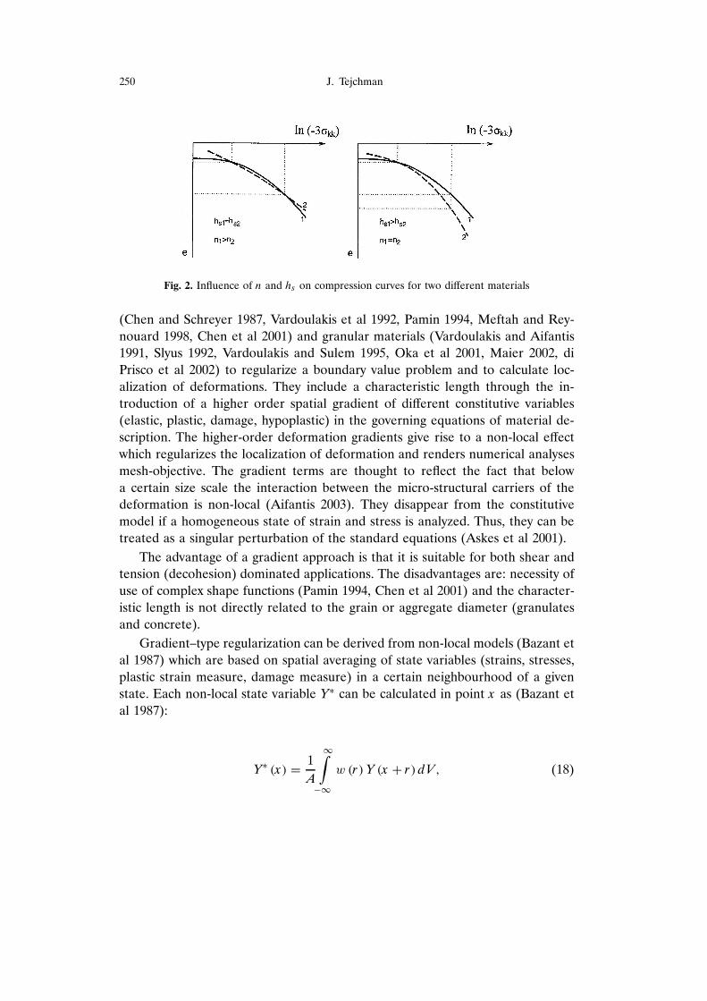
The constitutive relationship requires 7 material constants: ei0; ed0, ec0, �c,hs , n and Þ. The FE-analyses were carried out with the following material con-stants (for so-called Karlsruhe sand): ei0 D 1:3, ed0 D 0:51, ec0 D 0:82, �c D 30Ž,hs D 190 MPa, n D 0:5 and Þ = 0.3 (Bauer 1996). The parameters hs and n areestimated from a single oedometric compression test with an initially loose speci-men (hs reflects the slope of the curve in a semi-logarithmic representation, andn its curvature, Fig. 2). The constant Þ is found from a triaxial test with a densespecimen (it reflects the height and position of the peak value of the stress-straincurve). The angle �c is determined from the angle of repose or measured in atriaxial test with a loose specimen. The values of ei0; ed0; ec0 are obtained withconventional index tests (ec0 ³ emax, ed0 ³ emin, ei0 ³ .1:1 � 1:5/emax . The meangrain diameter of sand is d50 = 0.5 mm.
3. Gradient Hypoplasticity
Gradient approaches have been proposed for ductile materials (metals), (Fleckand Hutchinson 1997, Chen et al 2001), quasi-brittle materials (rock, concrete)
250 J. Tejchman
Fig. 2. Influence of n and hs on compression curves for two different materials
(Chen and Schreyer 1987, Vardoulakis et al 1992, Pamin 1994, Meftah and Rey-
nouard 1998, Chen et al 2001) and granular materials (Vardoulakis and Aifantis
1991, Slyus 1992, Vardoulakis and Sulem 1995, Oka et al 2001, Maier 2002, di
Prisco et al 2002) to regularize a boundary value problem and to calculate loc-
alization of deformations. They include a characteristic length through the in-
troduction of a higher order spatial gradient of different constitutive variables
(elastic, plastic, damage, hypoplastic) in the governing equations of material de-
scription. The higher-order deformation gradients give rise to a non-local effect
which regularizes the localization of deformation and renders numerical analyses
mesh-objective. The gradient terms are thought to reflect the fact that below
a certain size scale the interaction between the micro-structural carriers of the
deformation is non-local (Aifantis 2003). They disappear from the constitutive
model if a homogeneous state of strain and stress is analyzed. Thus, they can be
treated as a singular perturbation of the standard equations (Askes et al 2001).
The advantage of a gradient approach is that it is suitable for both shear and
tension (decohesion) dominated applications. The disadvantages are: necessity of
use of complex shape functions (Pamin 1994, Chen et al 2001) and the character-
istic length is not directly related to the grain or aggregate diameter (granulates
and concrete).
Gradient–type regularization can be derived from non-local models (Bazant et
al 1987) which are based on spatial averaging of state variables (strains, stresses,
plastic strain measure, damage measure) in a certain neighbourhood of a given
state. Each non-local state variable YŁ can be calculated in point x as (Bazant et
al 1987):
YŁ .x/ D1
A
1Z
�1
w .r / Y .x C r / dV; (18)

Simulation of Shear Localization in Granular Bodies : : : 251
where r is the distance from the material point compared to other points of the
entire material body, w is the weighting function, Y is local state variable, V
denotes the volume and A is the weighted body area:
A D1
Z
�1
w .r / dV : (19)
As the weighting function w; the error density function is usually chosen
(Brinkgreve 1994, Maier 2002):
w .r / D1
lp
³e�.r= l/2
: (20)
The parameter l denotes a characteristic length (it determines the size of the
neighbourhood influencing the state at the given point). At the distance of a few
times the length l , the function w is equal to zero (Fig. 3). The characteristic
length l in Eq. 20 can be related to dimensions of the material micro-structure on
the basis of comparative calculations on localization of deformation (Tejchman
2003).
Fig. 3. Distribution of the weighting function w
By expanding the state variable Y.x C r / in Eq. 18 into a Taylor series around
the point r = 0, choosing the error function w (Eq. 20) as the weighting function
and neglecting terms higher than second order, the following relationship is ob-
tained for a non-local gradient variable (one-dimensional problems), (Brinkgreve
1994, Pamin 1994)

252 J. Tejchman
YŁ .x/ D1
A
2
4
1Z
�1
1
lp
³e�.r= l/2
Y.x/dr C1
Z
�1
r
lp
³e�.r= l/2 dY.x/
dxdrC
C1
Z
�1
r 2
2lp
³e�.r= l/2 d2Y .x/
dx2dr C
1Z
�1
r 3
6lp
³e�.r= l/2 d3Y .x/
dx3drC
C1
Z
�1
r 4
24lp
³e�.r= l/2 d4Y .x/
dx4dr C ::::
3
5 D Y C l@Y
@xC
l2
4
@2Y
@x2:
(21)
The odd derivative can be cancelled because of the implicit assumption ofisotropy (de Borst et al 1992). Restricting the treatment to the second-order de-rivative, each non-local state variable is equal to
YŁ.x/ D Y Cl2
4
@2Y
@x2: (22)
In the FE-calculations, the second gradient of the modulus of the deformationrate (Eq. 6)
d Dp
dkldkl (23)
was taken into account. This parameter is always positive and strongly affectedby shear localization (Tejchman 2003, 2004a). Thus, the enhanced (non-local)modulus of the deformation rate dŁ was calculated for two-dimensional problemsin the following way
dŁ .x ; y/ D d Cl2
4
�
@2d
@x2C
@2d
@y2C 2
@2d
@x@y
�
: (24)
Alternatively, the enhanced (non-local) density factor fd of Eq. 10 can be used(Tejchman 2003).
Instead of using complex shape functions to describe the evolution of thesecond gradient of d, a standard central difference scheme was applied (Alehos-sein and Korinets 2001, di Prisco et al 2002, Zhou et al 2002) which assumesa parabolic interpolation of the function dŁ (the variable d is influenced by thevalues only in adjacent elements). From the theory of finite difference method, forthe variable dŁ (when the difference paces dx and dy are infinitesimal) the secondderivatives can be approximated in each element (when the mesh is regular in thevertical and horizontal direction) according to Fig. 4 as:
@2d5
@x2D
d8 � 2d5 C d2
dx2; (25)
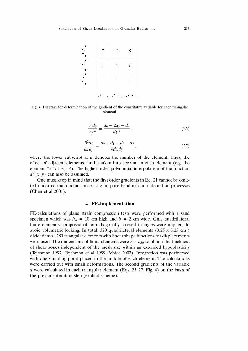
Simulation of Shear Localization in Granular Bodies : : : 253
Fig. 4. Diagram for determination of the gradient of the constitutive variable for each triangularelement
@2d5
@y2D
d6 � 2d5 C d4
dy2; (26)
@2d5
@x@yD
d9 C d1 � d3 � d7
4dxdy; (27)
where the lower subscript at d denotes the number of the element. Thus, theeffect of adjacent elements can be taken into account in each element (e.g. theelement “5” of Fig. 4). The higher order polynomial interpolation of the functiondŁ .x ; y/ can also be assumed.
One must keep in mind that the first order gradients in Eq. 21 cannot be omit-ted under certain circumstances, e.g. in pure bending and indentation processes(Chen et al 2001).
4. FE-Implementation
FE-calculations of plane strain compression tests were performed with a sandspecimen which was ho = 10 cm high and b = 2 cm wide. Only quadrilateralfinite elements composed of four diagonally crossed triangles were applied, to
avoid volumetric locking. In total, 320 quadrilateral elements (0:25 ð 0:25 cm2/
divided into 1280 triangular elements with linear shape functions for displacementswere used. The dimensions of finite elements were 5 ð d50 to obtain the thicknessof shear zones independent of the mesh size within an extended hypoplasticity(Tejchman 1997, Tejchman et al 1999, Maier 2002). Integration was performed
with one sampling point placed in the middle of each element. The calculationswere carried out with small deformations. The second gradients of the variabled were calculated in each triangular element (Eqs. 25–27, Fig. 4) on the basis ofthe previous iteration step (explicit scheme).
254 J. Tejchman
As the initial stress state, a K0-state with ¦22 D ¦c C dx2 and ¦11 D ¦c CK0 dx2 was assumed in the sand specimen where ¦c denotes the confining pres-
sure, x2 is the vertical coordinate measured from the top of the specimen, d
denotes the initial volume weight and K0 D 0:47 is the earth pressure coefficient
at rest (¦11 – horizontal normal stress, ¦22 – vertical normal stress).
A quasi-static deformation in sand was initiated through a constant vertical
displacement increment prescribed at nodes along the upper edge of the specimen.
The boundary conditions of the sand specimen were: no shear stress at the top and
bottom. To preserve the stability of the specimen against horizontal sliding along
the top boundary, the node in the middle of the bottom was kept fixed. Along all
boundaries, all derivatives of the modulus of the deformation rate (Eq. 24) were
set at zero analogously to elasto-plastic FE-solutions where the derivative of the
plastic multiplier is assumed to be zero at boundaries (Pamin 1994, de Borst and
Pamin 1996).
To obtain a shear zone inside the specimen, a weaker element with a high
initial void ratio, e0 D 0:90, was inserted at mid-point of the specimen.
For the solution of a non-linear system, a modified Newton-Raphson scheme
with line search was used with a global stiffness matrix calculated with only first
term of the constitutive equations (linear in dkl/. The stiffness matrix was updated
every 100 steps. To accelerate the calculations in the softening regime, the initial
increments of displacements in each calculation step were assumed to be equal
to the final increments in the previous step. The iteration steps were performed
using translational convergence criteria.
The gradient hypoplastic constitutive model was implemented in the author’s
finite element code.
5. FE-Results
5.1. Classical Continuum
Figures 5 and 6 present the results of plane strain compression with dense sand
(eo D 0:60) within a conventional (local) continuum (Eqs. 1–17) under confining
pressure ¦ c D 0:2 MPa (Tejchman 2003). The normalized load-displacement curve
is depicted in Fig. 5a. Figure 5b shows the deformed FE-mesh with the distribution
of void ratio. The darker the region, the higher the void ratio. The evolution of
the void ratio e; density factor fd (Eq. 10), modulus of the deformation rate d
(Eqs. 6) and Lode angle � (Eq. 16) at two different locations: inside the shear
zone and far beyond it are demonstrated in Fig. 6.
The resultant vertical force on the specimen top P increases first, shows a pro-
nounced peak, drops later and reaches a residual state (Fig. 5a). The overall angle
of internal friction for the sand specimen, calculated from Mohr’s formula
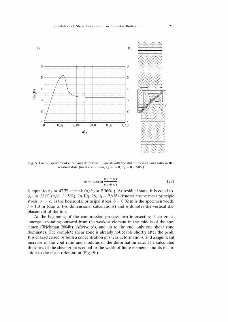
Simulation of Shear Localization in Granular Bodies : : : 255
Fig. 5. Load-displacement curve and deformed FE-mesh with the distribution of void ratio in theresidual state (local continuum, eo D 0:60, ¦ c D 0:2 MPa)
� D arcsin¦1 � ¦3
¦1 C ¦3(28)
is equal to �p = 42.7o at peak (u=h0 = 2.36% ). At residual state, it is equal to�cr = 32.0o (u=h0
¾D 5%). In Eq. 28, ¦1D P=.bl/ denotes the vertical principlestress, ¦3 D ¦c is the horizontal principal stress, b D 0:02 m is the specimen width,l D 1:0 m (due to two-dimensional calculations) and u donotes the vertical dis-placement of the top.
At the beginning of the compression process, two intersecting shear zonesemerge expanding outward from the weakest element in the middle of the spe-cimen (Tejchman 2004b). Afterwards, and up to the end, only one shear zonedominates. The complete shear zone is already noticeable shortly after the peak.It is characterized by both a concentration of shear deformations, and a significantincrease of the void ratio and modulus of the deformation rate. The calculatedthickness of the shear zone is equal to the width of finite elements and its inclin-ation to the mesh orientation (Fig. 5b).

256 J. Tejchman
Fig. 6. Evolution of void ratio e (A), density factor fd (B), modulus of the deformation rate d (C)and Lode angle � (D) (a – outside the shear zone, b – in the shear zone)
The void ratio e at the beginning decreases (up to u=h0 D 1%) and after-wards increases in the whole specimen (Fig. 6A). In the shear zone, it reachesa pressure-dependent critical value at residual state (e D ec D 0:745, Eq. 13). Bey-ond the shear zone, the void ratio reaches the initial value. The thickness of theshear zone on the basis of an increase of the void ratio is slightly larger, sincea dense granular material already dilates before a shear zone forms.
The density factor fd (Eq. 10) continuously increases in the whole specimen(Fig. 6B). At residual state, it is equal to 1.0 (shear zone) and 0.8 (remainingregion).
The modulus of the deformation rate d increases uniformly in the whole spe-cimen at the beginning of loading, to u=h0 = 2.2%. Later, it is significant only inthe shear zone (Fig. 6C). It increases strongly in the range of u=h0 D 2 � 3%. Af-terwards, it decreases and approaches an asymptote. On the basis of the differencebetween the modulus of the deformation rate in the shear zone and beyond it,one can find that the shear zone occurs before the peak of the load-displacementcurve at u=h0 D 2:2%.
The Lode angle � (Eq. 13) is equal to 30o in the shear zone and 25o beyondthe shear zone (residual state), Fig. 6D.

Simulation of Shear Localization in Granular Bodies : : : 257
5.2. Gradient Continuum
The results with the modulus of the deformation rate enhanced by its secondgradient dŁ (Eq. 24) for dense sand (eo D 0:60; ¦ c D 0:2 MPa) are shown in Figs.7–12.
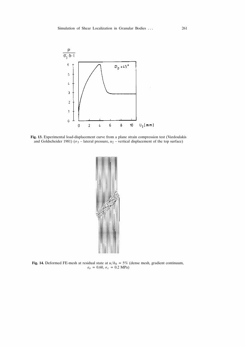
The greater the characteristic length, the greater both the maximum normal-ized vertical force on the top, and the greater the vertical displacement of thetop corresponding to the peak and residual force (Figs. 7 and 9). The materialbecomes more ductile with increasing l : The size effect due to l=L (L D h0/ isfor dense sand almost linear (Fig. 9). In reality, this effect could be greater dueto the fact that the characteristic length influences the material properties (e.g.the larger mean grain diameter, the greater both the maximum internal frictionand dilatancy angles). The mean angles of internal friction for the entire sandspecimen are equal to �p D 42:8Ž � 43:3Ž (at peak). The residual internal frictionangle, 32.2Ž, is not influenced by l in the investigated range:The obtained resultsof internal friction angles at peak and in the residual state in dense sand, andthe corresponding vertical displacements of the sand specimen compare well withexperimental results with Karlsruhe sand carried out by Vardoulakis and Gold-scheider (1981), Fig. 13. In the plane strain compression tests by Vardoulakis andGoldscheider (1981) the dimension of the specimen were: h0 = 140 mm, b = 40mm and l D 80 mm. The experiments with very dense sand (eo = 0.55) resultedin �p = 45.0o and �cr = 32.9o at ¦ c = 200 kPa. The shape of the calculatedload-displacement curves is close to the experimental one. However, the calcu-lated stiffness is too high before the peak (in the hardening region).
Fig. 7. Normalized load-displacement curves (gradient continuum, eo = 0.60, ¦ c = 0.2 MPa):a) l = 0.0 mm;b) l = 0.5 mm, c) l = 1.0 mm, d) l = 2.0 mm
The thickness of the internal shear zone grows with increasing l and is (onthe basis of shear deformation): tsz
¾D 5:5 mm D 11ð l .l D 0:5 mm), tsz¾D 7:3
258 J. Tejchman
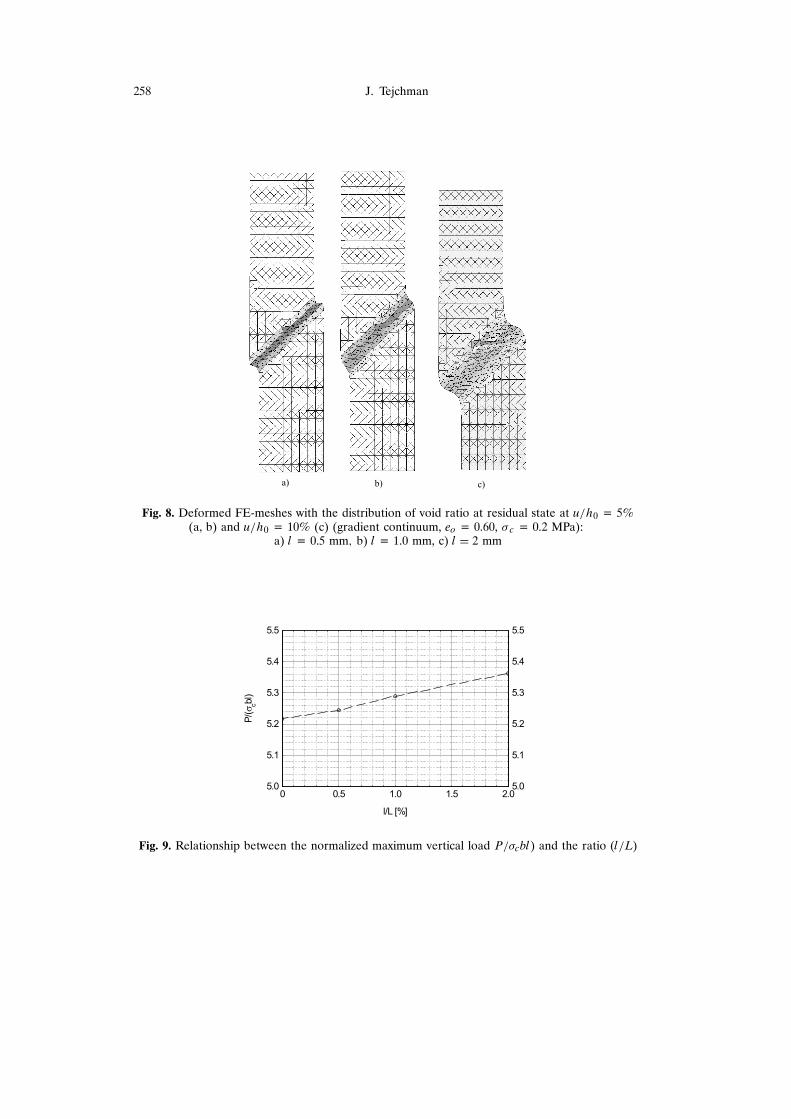
Fig. 8. Deformed FE-meshes with the distribution of void ratio at residual state at u=h0 = 5%(a, b) and u=h0 = 10% (c) (gradient continuum, eo = 0.60, ¦ c = 0.2 MPa):
a) l = 0.5 mm; b) l = 1.0 mm, c) l D 2 mm
Fig. 9. Relationship between the normalized maximum vertical load P=¦cbl) and the ratio (l=L)

Simulation of Shear Localization in Granular Bodies : : : 259
mm ¾D 7 ð l .l D 1:0 mm) and tsz¾D 11:2 mm ¾D 5 ð l .l D 2:0 mm), Fig. 8. If the
characteristic length is greater than l D 2:5 mm, the shear zone does not appearand the diffuse deformations are concentrated at the bottom of the specimen.The calculated thickness of the shear zone in dense Karlsruhe sand with l D 1mm is in accordance with the observed thickness during experiments at ¦ c =200 kPa: tsz D 13 ð d50 (Vardoulakis 1977, 1980, Vardoulakis and Goldscheider1981) and 10 ð d50 (Yoshida et al 1994) (d50 D 0:4 � 0:5). Thus, one can assumethat the characteristic length of the gradient continuum is equal to two meangrain diameters in the case of Karlsruhe sand i.e. l ¾D 2 ð d50 (as in the non-localhypoplastic continuum, Tejchman 2003, 2004a). The thickness of the shear zoneis not affected by the mesh size (Fig. 14). The results of Fig. 14 were obtainedwith the FE-mesh consisting of 1280 quadrilateral elements (0:125 ð 0:125 cm2/
divided into 5120 triangular elements.
The void ratio (Fig. 10) and the density factor (Fig. 11) in the shear zone areslightly smaller in the residual state than in the conventional continuum (Figs. 6Aand 6B): e = 0.742 and fd D 0:987.
Fig. 10. Evolution of void ratio e inside the shear zone (gradient continuum, l = 1.0 mm,eo = 0.60, ¦ c = 0.2 MPa)
On the basis of the evolution of the gradient modulus of deformation in theshear zone (Fig. 12) at the beginning of loading, one can deduce that the shearzone occurs slightly before the peak of the vertical force on the top at u=h0
= 2.2% (the peak value appears at u=h0 = 2.5% with l D 1 mm). The secondgradient of d becomes noticeable only in the shear zone during softening. Afterthe peak, the enhanced modulus dŁ is smaller than the local one d.
Compared to non-local (Tejchman 2003, 2004a) and polar (Tejchman et al1999, Tejchman 2004b) numerical analyses, the gradient theory provides similarrobust FE-results. However, it requires less computation time than the non-localone and is easier to implement than the polar one.

260 J. Tejchman
Fig. 11. Evolution of density factor fd inside the shear zone (gradient continuum, l D 1:0 mm,eo D 0:60, ¦ c D 0:2 MPa)
Fig. 12. Evolution of the modulus of the deformation rate d (a) and dŁ (b) in the shear zone(gradient continuum, l = 1.0 mm; eo = 0.60, ¦ c = 0.2 MPa)
6. Conclusions
The FE-calculations of a plane strain compression test for granular materialsdemonstrate that the mesh dependence inherent in classical plasticity is remediedusing the gradient approach allowing for robust localization computations.
The gradient hypoplastic model provides full regularization of the boundaryvalue problem during plane strain compression.
The normalized vertical force on the top increases linearly with increasingcharacteristic length (using the same parameters as other material).
The thickness of the localized shear zone increases with increasing character-istic length.
The characteristic length of the gradient approach can be calibrated for dif-ferent sands with a numerical analysis of a laboratory plane strain compressiontest.
Simulation of Shear Localization in Granular Bodies : : : 261
Fig. 13. Experimental load-displacement curve from a plane strain compression test (Vardoulakisand Goldscheider 1981) (¦ 3 – lateral pressure, u2 – vertical displacement of the top surface)
Fig. 14. Deformed FE-mesh at residual state at u=h0 = 5% (dense mesh, gradient continuum,eo = 0.60, ¦ c = 0.2 MPa)
262 J. Tejchman
References
Aifantis E. (1984), On the Microstructural Origin of Certain Inelastic Models, Trans. ASME J.Mat. Engng. Technol., 106, 326–330.
Aifantis E. (2003), Update on Class of Gradient Theories, Mechanics of Materials 35, 259–280.
Alehossein H., Korinets A. (2001), Gradient Dependent Plasticity and the Finite DifferenceMethod, in: Bifurcation and Localisation Theory in Geomechanics (H. B. Muhlhaus et al,eds), Swets and Zeitlinger, Lisse, 117–124.
Askes H., Suiker A. S. J., Sluys L. J. (2001), Dispersion Analysis and Numerical Simulations ofSecond-Order and Fourth-Order Strain Gradient Models Based on a Microstructure, Proc.ECCM-2001, Cracow, Poland, 1–20.
Bauer E. (1996), Calibration of a Comprehensive Hypoplastic Model for Granular Materials, Soilsand Foundations, 36, 1, 13-26.
Bazant Z., Lin F., Pijaudier-Cabot G. (1987), Yield Limit Degradation: Non-Local ContinuumModel with Local Strain, Proc. Int. Conf. Computational Plasticity, Barcelona. In: Owen,editor, 1757–1780.
Belytschko T., Chiang H., Plaskacz E. (1994), High Resolution Two Dimensional Shear BandComputations: Imperfections and Mesh Dependence, Com. Meth. Appl. Mech. Engng., 119,1–15.
Benallal A., Billardon R., Geymonat G. (1987), Localization Phenomena at the Boundaries andInterfaces of Solids, Proc. of the 3rd Int. Conf. Constitutive Laws for Engineering Materials:Theory and Applications, Tucson, Arizona. In: C. S. Desai et al, editors, 387–390.
Borst R. de, Muhlhaus H. B. (1992), Gradient dependent plasticity: formulation and algorithmicaspects, Int. J. Numer. Methods Engng., 35, 521–539.
Borst R. de, Muhlhaus H. B., Pamin J., Sluys L. (1992), Computational Modelling of Localizationof Deformation, Proc. of the 3rd Int. Conf. Comp. Plasticity, In: D. R. J. Owen, H. Onate,E. Hinton, eds., Swansea, Pineridge Press, 483–508.
Borst R. de, Pamin J. (1996), Some Novel Developments in Finite Element Procedures forGradient-Dependent Plasticity, Int. J. Numer. Meth. Eng., 39 (14), 2477–2502.
Borst R. de (1998), On Gradient-Enhanced Coupled Plastic Damage Theories, in: ComputationalMechanics (S. Idelsohn, E. Onate, E. Dvorkin, eds.), Barcelona, Spain.
Borst R. de, Pamin J., Geers M. G. D. (1999), On Coupled Gradient Theory, Eur. J. Mech. A-Solid18, 6, 939–962.
Brinkgreve R. (1994), Geomaterial Models and Numerical Analysis of Softening, Dissertation,Delft University, 1–153.
Chambon R., Caillerie D., Matsuchima T. (2001), Plastic Continuum with Microstructure, LocalSecond Gradient Theories for Geomaterials: Localization Studies, Int. J. Solids and Struc-tures, 38, 8503–8527.
Chen J., Yuan H., Kalkhof D. (2001), A Non-Local Damage Model for Elastoplastic MaterialsBased on Gradient Plasticity Theory, Bericht Paul Scherrer Institut, 1–130.
Chen Z., Schreyer H. L. (1987), Simulation of Soil-Concrete Interfaces with Non-Local Con-stitutive Models, J. Engng. Mech., 113, 1665–1677.
Dasgupta S., Sengupta D. (1990), A Higher Order Triangular Plate Bending Element – DependentPlasticity and Damage Revisited, Int. J. Num. Meth. Engng., 30, 419–430.
Desrues J., Chambon R., Mokni M., Mazerolle F. (1996), Void ratio evolution inside shear bandsin triaxial sand specimens studied by computed tomography, Geotechnique, 46, 3, 529–546.
Ehlers W., Volk W. (1998), Fundamental Considerations on the Numerical Investigation of ShearBand Phenomena in Saturated and Non-Saturated Frictional Porous Materials, Computa-tional Mechanics – New Trends and Applications. In: S. Idelsohn, E. Onate, E. Dworkin,editors, CIMNE Barcelona, 1–21.

Simulation of Shear Localization in Granular Bodies : : : 263
Fleck N. A., Hutchinson J. W. (1993), A Phenomenological Theory for Strain Gradient Effects inPlasticity, J. Mechanics and Physics of Solids, 41, 12, 1825–1857.
Fleck N. A., Hutchinson J. W. (1997), Strain Gradient Plasticity, Adv. Appl. Mech., 33, 295–361.
Fremond M., Nedjar B. (1996), Damage, Gradient of Damage and Principle of Virtual Power, I.J. Solids and Structures, 33, 8, 1083–1103.
Gudehus G., (1996), A Comprehensive Constitutive Equation for Granular Materials, Soils andFoundations, 36, 1, 1–12.
Hassan A. H. (1995), Etude Experimentale et Numerique du Comportement Local et Globald’une Interface Sol Granulaire Structure, Dissertation, Grenoble University.
Herle I., Gudehus G. (1999), Determination of Parameters of a Hypoplastic Constitutive Modelfrom Grain Properties, Mechanics of Cohesive-Frictional Materials, 4, 5, 461–486.
Kolymbas D. (1977), A Rate-Dependent Constitutive Equation for Soils, Mech. Res. Comm., 6,367–372.
Kuhl E., Ramm E. (2000), Simulation of Strain Localization with Gradient Enhanced DamageModels, Computational Materials Sciences, 16, 176–185.
Lade P. V. (1977), Elasto-Plastic Stress-Strain Theory for Cohesionless Soil with Curved YieldSurfaces, Int. J. Solid Structures., 13, 1019–1035.
Leśniewska D. (2000), Analysis of Shear Band Pattern Formation in Soil, Habilitation, Instituteof Hydro-Engineering of the Polish Academy of Sciences, Gdańsk.
Leśniewska D., Mróz Z. (2003), Shear Bands in Soil Deformation Processes, in: Bifurcationsand Instabilities in Geomechanics (J. Labuz and A. Drescher, eds), Swets and Zeitlinger,109–119.
Łodygowski P. V., Perzyna P. (1997), Numerical Modelling of Localized Fracture of Inelastic Solidsin Dynamic Loading Process, Int. J. Num. Meth. Eng., 40, 22, 4137–4158.
Maier T. (2002), Numerische Modellierung der Entfestigung im Rahmen der Hypoplastizitat, PhDThesis, University of Dortmund.
Meftah F., Reynouard J. M. (1998), A Multilayered Mixed Beam Element in Gradient Plasticityfor the Analysis of Localized Failure Mode, Mechanics of Cohesive-Frictional Materials, 3,305–322.
Muhlhaus H.-B. (1989), Application of Cosserat Ttheory in Numerical Solutions of Limit LoadProblems, Ing. Arch., 59, 124–137.
Muhlhaus H.-B. (1990), Continuum Models for Layered and Blocky Rock, Comprehensive RockEngineering, In: J. A. Hudson, Ch. Fairhurst, editors, 2, 209–231, Pergamon Press.
Neddleman A. (1998), Material Rate Dependence and Mesh Sensitivity in Localization Problems,Comp. Meths. Appl. Mech. Eng., 67, 69–85.
Niemunis A., Maier T. (2004), Towards Gradient Continuum with Hypoplastic Model (underpreparation).
Oka F., Jing M., Higo Y. (2001), Effect of Transport of Pore Water on Strain Localisation Analysisof Fluid-Saturated Strain Gradient Dependent Viscoplastic Geomaterial, in: Bifurcation andLocalisation Theory in Geomechanics (H. B. Muhlhaus et al, eds), Swets and Zeitlinger,Lisse, 77–83.
Pamin J. (1994), Gradient Dependent Plasticity in Numerical Simulation of Localisation Phenom-ena, PhD Thesis, Delft University.
Peerlings R. H. J., Borst R. de, Brekelmans W. A. M., Geers M. G. D. (1998), Gradient-EnhancedDamage Modelling of Concrete Fracture, Mechanics of Cohesive-Frictional Materials, 3,323–342.
Pestana J. M., Whittle A. J. (1999), Formulation of a Unified Constitutive Model for Clays andSands, Int. J. Num. Anal. Meth. Geomech., 23, 1215–1243.
264 J. Tejchman
Pijaudier-Cabot G. (1995), Non Local Damage, Continuum Models for Materials with Microstruc-ture. In: H. B. Muhlhaus, editor, John Wiley & Sons Ltd, 105–143.
Prisco C. di, Imposimato S., Aifantis E. C. (2002), A Visco-Plastic Constitutive Model for GranularSoils Modified According to Non-Local and Gradient Approaches, Int. J. Num. and Anal.Meth. Geomech., 26, 121–138.
Sluys L. Y. (1992), Wave Propagation, Localisation and Dispersion in Softening Solids, PhDThesis, Delft University of Technology.
Sluys L. J., Borst R. de (1994), Dispersive Properties of Gradient and Rate-Dependent Media,Mech. Mater., 183, 131–149.
Tatsuoka F., Okahara M., Tanaka T., Tani K., Morimoto T., Siddiquee M. S. (1991), ProgressiveFailure and Particle Size Effect in Bearing Capacity of Footing on Sand, Proc. of the ASCEGeotechnical Engineering Congress, 27, 2, 788–802.
Tatsuoka F., Siddiquee M. S., Yoshida T., Park C. S., Kamegai Y., Goto S., Kohata Y. (1994), TestingMethods and Results of Element Tests and Testing Conditions of Plane Strain Model BearingCapacity Tests using Air-Dried Dense Silver Buzzard Sand, Internal Report, University ofTokyo, 1–129.
Tejchman J. (1989), Scherzonenbildung und Verspannungseffekte in Granulaten unter Berucksichtigungvon Korndrehungen, Publication Series of the Institute of Soil and Rock Mechanics, Uni-versity Karlsruhe, 117, 1–236.
Tejchman J., Wu W. (1993), Numerical Study on Shear Band Patterning in a Cosserat Continuum,Acta Mechanica, 99, 61–74.
Tejchman J. (1997), Modelling of Shear Localisation and Autogeneous Dynamic Effects in Gran-ular Bodies, Publication Series of the Institute for Soil and Rock Mechanics, UniversityKarlsruhe, 140.
Tejchman J., Herle I., Wehr J. (1999), FE-Studies on the Influence of Initial Void Ratio, PressureLevel and Mean Grain Diameter on Shear Localization, Int. J. Num. Anal. Meth. Geomech.,23, 15, 2045–2074.
Tejchman J. (2002), Patterns of Shear Zones in Granular Materials within a Polar HypoplasticContinuum, Acta Mechanica, 155, 1–2, 71–95.
Tejchman J. (2003), A Non-Local Hypoplastic Constitutive Law to Describe Shear Localisationin Granular Bodies, Archives of Hydro-Engineering and Environmental Mechanics, 50, 4,229–250.
Tejchman J. (2004a), Comparative FE-Sof Shear Localizations in Granular Bodies within a Polarand Non-Local Hypoplasticity, Mechanics Research Communications, 31/3, 341–354.
Tejchman J. (2004b), Effect of Heterogeneity on Shear Zone Formation During Plane StrainCompression, Archives of Hydro-Engineering and Environmental Mechanics, 51, 2, 149–183.
Triantafyllidis N., Aifantis E. C. (1986), A Gradient Approach to Localization of Deformation,Hyperelastic Materials, J. Elasticity 16, 225–238.
Uesugi M., Kishida H., Tsubakihara Y. (1988), Behaviour of Sand Particles in Sand-Steel Friction,Soils and Foundations, 28, 1, 107–118.
Vardoulakis I. (1977), Scherfugenbildung in Sandkorpern als Verzweigungsproblem, Dissertation,Institute for Soil and Rock Mechanics, University of Karlsruhe, 70.
Vardoulakis I. (1980), Shear Band Inclination and Shear Modulus in Biaxial Tests, Int. J. Num.Anal. Meth. Geomech., 4, 103–119.
Vardoulakis I., Goldscheider M. (1981), Biaxial Apparatus for Testing Shear Bands in Soils, Proc.10th Conf. Soil Mech. Found. Engng., Stockholm, 819–824.
Vardoulakis I., Aifantis E. (1991), A Gradient Flow Theory of Plasticity for Granular Materials,Acta Mechanica 87, 197–217.
Simulation of Shear Localization in Granular Bodies : : : 265
Vardoulakis I., Shah K. R., Papanastasiou P. (1992), Modelling of Tool-Rock Shear Interfaces usingGradient-Dependent Flow Theory of Plasticity, Int. J. Rock Mech. Min. Sci. Geomech., 29,6, 573-582.
Vardoulakis I., Sulem J. (1995), Bifurcation Analysis in Geomechanics, Blackie Academic andProfessional, Glasgow.
Vermeer P. (1982), A Five-Constant Model Unifying Well-Established Concepts, Proc. Int. Work-shop on Constitutive Relations for Soils (eds. G. Gudehus, F. Darve, I. Vardoulakis),Balkema, 175–197.
Voyiadjis G. Z., Dorgan R. J. (2001), Gradient Formulation in Coupled Damage-Plasticity, Arch.of Mech., 53, 565–597.
Wang C. C. (1970), A New Representation Theorem for Isotropic Functions, J. Rat. Mech. Anal.,36, 166–223.
Wolffersdorff P. A. von (1996), A Hypoplastic Relation for Granular Materials with a PredefinedLimit State Surface, Mechanics Cohesive-Frictional Materials, 1, 251–271.
Wu W., Niemunis A. (1996), Failure Criterion, Flow Rule and Dissipation Function Derived fromHypoplasticity, Mechanics of Cohesive-Frictional Materials, 1, 145–163.
Xia Z. C., Hutchinson J. W. (1997), Steady-State Crack Growth and Work of Fracture for SolidsCharacterized by Strain Gradient Plasticity, J. Mechanics and Physics of Solids, 45, 8,1253–1273.
Yoshida T., Tatsuoka F., Siddiquee M. (1994), Shear Banding in Sands Observed in Plane StrainCompression, Localisation and Bifurcation Theory for Soils and Rocks. In: R. Chambon,J. Desrues and I. Vardoulakis, editors, 165–181, Balkema, Rotterdam.
Zbib H., Aifantis E. (1988a), On the Localisation and post Localisation of Plastic Deformation,Part 1, On the Initiation of Shear Bands, Res. Mechanica, 23, 261–277.
Zbib H., Aifantis E. (1988b), On the Localisation and Post Localisation of Plastic Deformation,Part 1, On the Evolution and Thickness of Shear Bands, Res. Mechanica, 23, 279–292.
Zbib H. M., Rhee M., Hirth J. P. (1998), On Plastic Deformation and the Dynamics of 3DDislocations, Int. J. Mech. Sci., 40, 113–127.
Zervos Z., Papanastasiou P., Vardoulakis I. (2001), A Finite Element Displacement Formulationfor Gradient Plasticity, Int. J. Numer. Methods in Engineering, 50, 1369–1388.
Zhou W., Zhao J., Liu Y., Yang Q. (2002), Simulation of Localization with Strain-Gradient-EnhancedDamage Mechanics, Int. J. Num. And Anal. Meth. Geomech., 26, 793–813.