simulation of spacer grid with mixing vane on...
TRANSCRIPT
The 15th International Topical Meeting on Nuclear Reactor Thermal - Hydraulics, NURETH-15 NURETH15-324 Pisa, Italy, May 12-17, 2013
SIMULATION OF SPACER GRID WITH MIXING VANE ON A TYPICAL PWR FUEL
ROD BUNDLE SYSTEM USING LATTICE BOLTZMANN METHOD
A. Tiftikçi1, H. Ayhan
2 , C. Kocar
3 and C.N.Sökmen
4
1,4 Department of Nuclear Engineering, Hacettepe University, Beytepe, 06800, Ankara, Turkey
[email protected], [email protected], [email protected],
ABSTRACT
In present paper, the effect of spacer grid on adiabatic single phase flow in a
typical nuclear reactor fuel assembly is investigated. Spacer grid with mixing vane
of PWR subchannel is simulated. Velocity and pressure profiles for flow around
the spacer grid and fuel rod are analysed. Simulation results of 2x2 Pressurized
Water Reactor (PWR) rod bundle system with spacer grids and mixing vane are
presented. The simulations have been carried out using lattice-Boltzmann method.
Flow regime in flow channel is assumed to be laminar and the rod bundle system
geometry is nearly realistic. This work offers an alternative way to model nuclear
reactor rod bundle system which is the subject of many studies for researchers in
order to determine reactor thermal margin and safety. In the near future, turbulent
flow regime and heat transfer mechanisms will be adapted to this work.
1. INTRODUCTION
Fluid flow around rigid elements is one of the classical problems of fluid mechanics and has
been well studied because of its common occurrence in many forms and in different applications
[1-3]. These structures can be found both alone and in groups in the designs for heat exchangers,
cooling systems for nuclear power plants, offshore structures, power lines, struts, grids, screens
and cables in both single and multi-phase flows. A complete understanding of the fluid dynamics
for the flow around a kind body includes such fundamental subjects as the boundary layer,
separation, the free shear layer, the wake, and the dynamics of vortices. The flow field of
multiple-body configurations involves complex interactions between the shear layers, vortices
and Karman vortex streets [4]. The problem is further complicated by the large number of
configurations encountered in practise, resulting in different flow patterns, and by the effect of
their interactions. One of the applications of paramount importance in this study is fluid flow in
fuel rod bundles of water nuclear reactors. In this type of nuclear reactors, optimum heat removal
from the surface of fuel elements is the subject of many studies for researchers in order to
determine reactor thermal margin and safety [5-6].
In these reactors, spacer grids which support the fuel assembly are used as an effective mixing
device by attaching various types of flow deflectors. A nuclear fuel spacer grids used for
increasing the strength of fuel rod towards the mechanical stress, since fuel rods are about 3.5 m
long and coolant flow rate is respectably high. Besides their advantages, they carry some
disadvantages such as flow blockage and hence increase in pressure drop across the fuel bundle.
Spacers also change convective cooling characteristics. Mixing vane type spacer grids help
mixing near this blocked region. The mixing vanes are designed to guide the coolant from one

The 15th International Topical Meeting on Nuclear Reactor Thermal - Hydraulics, NURETH-15 NURETH15-324 Pisa, Italy, May 12-17, 2013
cell to neighbouring cells of the spacer grid, and thus, accomplishing a desired coolant mixing
effect and increasing the thermal allowance of the fuel rods and accomplishing a high
performance fuel assembly.
The mixing-vane type spacer design seen in Figure 1 is to provide vanes that are integrally
formed on the upper edges of the interlaced straps of a grid, and bent over in the flow channel so
as to deflect the upwardly flowing coolant. The vanes are formed in pairs with a slit and recess
between them, such that each vane can be bent in an opposite direction. This design was
optimized for size, strength and corrosion resistance. For typical mixing-vane design, the vane
angle bent from the vertical axis is generally between 20�and 30�. The bent vanes deflect the
coolant to mix between the subchannels of the spaced parallel fuel rods or to swirl within the
subchannel.
Spacer grids are small structures with respect to flow channel (~4% in radial and ~0.2% in
volume). Thus, detailed modelling of fluid flow requires long computational time and powerful
Central Processing Unit (CPU)for Finite Volume Method(FVM) based calculations. Moreover,
geometric decomposition (meshing) can be complicated process for this type of structures. On
the other hand, Cartesian noding (lattice) is used in Lattice-Boltzmann (LB) approach and the
use of this type of nodalization decreases the difficulties of pre-processing. LB method also
requires CPU but nodalization process is easier than Computational Fluid Dynamics (CFD)
calculations. Major drawback of LB method is its stability problem, thus, relatively large number
of iterations are needed until the flow reaches its steady-state behaviour.
The main goal of this study is to achieve successful calculation of flow distribution and pressure
drop in spacer region, since basic calculation of spacer grids is still challenging for CFD
modelling. In addition, this study might be seen as encouraging to model realistic nuclear reactor
rod-bundle systems with an alternative method known as lattice-Boltzmann approach.
2. LATTICE BOLTZMANN MODELS (LBM’S)
Lattice Boltzmann models vastly simplify Boltzmann’s original conceptual view by reducing the
number of possible particle spatial positions and microscopic momenta from a continuum to just
a handful and similarly discretising time into distinct steps. Particle positions are confined to the
nodes of the lattice [7].
Figure 1 – Spacer grids with mixing vane, arches and other elements
The 15th International Topical Meeting on Nuclear Reactor Thermal - Hydraulics, NURETH-15 NURETH15-324 Pisa, Italy, May 12-17, 2013
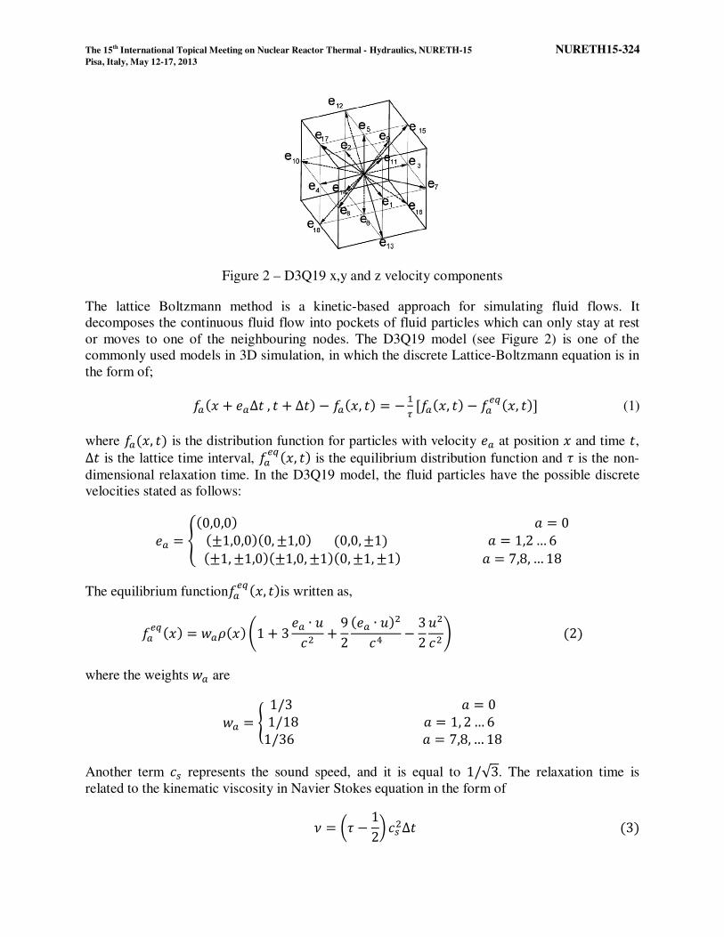
Figure 2 – D3Q19 x,y and z velocity components
The lattice Boltzmann method is a kinetic-based approach for simulating fluid flows. It
decomposes the continuous fluid flow into pockets of fluid particles which can only stay at rest
or moves to one of the neighbouring nodes. The D3Q19 model (see Figure 2) is one of the
commonly used models in 3D simulation, in which the discrete Lattice-Boltzmann equation is in
the form of;
��� + ��∆ , + ∆ � − ���, � = − �� [���, � − �����, �] (1)
where ���, � is the distribution function for particles with velocity �� at position and time , ∆ is the lattice time interval, �����, � is the equilibrium distribution function and � is the non-
dimensional relaxation time. In the D3Q19 model, the fluid particles have the possible discrete
velocities stated as follows:
�� = ��0,0,0� � = 0�±1,0,0��0, ±1,0� �0,0, ±1� � = 1,2 … 6 �±1, ±1,0��±1,0, ±1��0, ±1, ±1� � = 7,8, … 18 ! The equilibrium function�����, �is written as,
������ = "�#�� $1 + 3 �� ∙ &'( + 92 ��� ∙ &�('* − 32 &('( + �2�
where the weights "� are
"� = , 1/3 � = 01/18 � = 1, 2 … 6 1/36 � = 7,8, … 18! Another term '. represents the sound speed, and it is equal to 1/√3. The relaxation time is
related to the kinematic viscosity in Navier Stokes equation in the form of
0 = 1� − 122 '.(Δ �3�
The 15th International Topical Meeting on Nuclear Reactor Thermal - Hydraulics, NURETH-15 NURETH15-324 Pisa, Italy, May 12-17, 2013
Once the particle density distribution is known, the fluid density and momentum are calculated,
using:
# = 4�����5�67 �4�
& = 1# 4�������5�67 �5�
This simple equation allows us to pass from the discrete microscopic velocities that comprise the
LBM back to continuum of macroscopic velocities representing the fluids motion.
The next steps are streaming and collision of the particles via the distribution function. The
simplest approach uses the Bhatnagar-Gross-Krook Approximation [8] for collision.
3. INCOMPRESSIBLE FLUID FLOW IN LB APPROACH
Lattice Boltzmann (LB) simulations are supposed to represent the physics of an actually existing,
real system. During implementation, the question invariably pops up how to choose the units of
the simulated quantities, the lattice variables. Two constraints determine the choice of units.
First, the simulation should be equivalent, in a well-defined sense, to the physical system.
Second, the parameters should be fine-tuned in order to reach the required accuracy, i.e. the grid
should be sufficiently resolved, the discrete time step sufficiently small and so on [2]
3.1 Governing Equations
In an incompressible fluid, the density takes a constant value # = #7 which does not vary in time
and space. The equations of motion, the Navier-Stokes equations, are governed by the laws for
mass and momentum conservation. The conservation law for mass states that the velocity field is
divergence-less:
∇; ∙ &; = 0 �6�
Here, the index < indicates that variables and derivatives are evaluated in physical units. The
conservation law for momentum leads to the following relation:
=>?&; + @&; ∙ ∇;A&; = − 1#7? ∇;<; + 0;∇;( &; �7�
where <; is the pressure and B; is the kinematic viscosity in physical units.
3.2 Dimensionless Formulation
Equations (6) and (7) are now cast into a dimensionless form. For this, a length scale C7,; and a
time scale 7,; are introduced which are representative for the flow configuration. The length
The 15th International Topical Meeting on Nuclear Reactor Thermal - Hydraulics, NURETH-15 NURETH15-324 Pisa, Italy, May 12-17, 2013
C7could for example stand for the size of an obstacle which is immersed in the fluid, and 7,;
could be the time needed by a passive scalar in the fluid to travel a distance C7,;. The physical
variables such as the time ;and the position D;, are replaced by their dimensionless counterpart:
E = ; 7,; , DE = D;C7,; �8�
In the same manner, a unit conversion is introduced for the other variables, based on a
dimensional analysis:
&; = C7,; 7,; &E , =>? = 1 7,; =>F �9�
∇;= 1C7,; ∇E, <; = C7,;( 7,;( <E �10�
Plugging this change of variables into Equations (6) and (7) leads to the dimensionless version of
the Navier-Stokes equations:
∇E ∙ &E = 0 �11�
=>F&E + �&E ∙ ∇E�&E = −∇E<E + 1G� ∇E( &E �12�
where the dimensionless Reynolds number has been defined as
G� = C7,;( 7,;0; �13�
evaluated in any system of units. Two flows obeying the Navier-Stokes equations are equivalent
if they are embedded in the same geometry (except for a scaling factor) and have the same
Reynolds number.
Note that by expressing reference variables in the dimensionless system, one finds that C7,E = 1
and 7,E = 1. To help intuition, one may therefore consider the dimensionless system as the
system in which C7,; and 7,; are unity. It is also remarked that the viscosity in the dimensionless
system is 0E = 1/G�.
3.3 Discretization of Dimesionless System
The discrete space interval =I is defined as the reference length divided by the number of cells J
used to discretise this length. In the same way, => is defined as the reference time divided by the
number of iteration steps JK>�L needed to reach this time. Recall that both reference variables are
unity in the dimensionless system. Thus, the discretization parameters are

The 15th International Topical Meeting on Nuclear Reactor Thermal - Hydraulics, NURETH-15 NURETH15-324 Pisa, Italy, May 12-17, 2013
=I = 1/J, => = 1/JK>�L �14�
Other variables, such as velocity and viscosity, are easily converted between (D) and (LB)
through a dimensionless analysis:
&E = MIM> &NO , 0E = 1/G� = MI(M> 0NO �15�
and thus,
&NO = =>=I &E , 0NO = =>=I(1G� �16�
Finally, defining the reference velocity &7 = C7/ 7, one finds, by definition
&7,E = 1, &7,NO = =>=I �17�
4. COMPUTATIONAL PROCEDURES AND SETUP
4.1 Geometry Modelling
In present work, 2x2 subchannel of PWR nuclear reactor is modelled by lattice-Boltzmann
approach. The spacer and mixing vanes are treated as very thin surfaces. The other fuel spacer
elements such as the springs are neglected for simplicity because their effect on the flow mixing
is judged to be minimal only inside and near the spacer. The three-dimensional models are
developed by a structured lattice method. The size of the mixing vanes was assumed based on
typical PWR spacers. Cross-sectional view of spacer region is seen in Figure 3.
Figure 3 – Cross sectional view of spacer region
In Figure 3, red regions represent fuel rod; grey region represent spacer arches, mixing vanes and
spacer can; and blue regions represent flow domain.

The 15th International Topical Meeting on Nuclear Reactor Thermal - Hydraulics, NURETH-15 NURETH15-324 Pisa, Italy, May 12-17, 2013
4.2 Boundary and Flow Conditions
Flow is considered to be laminar even if the flow regime in real PWR coolant is turbulent.
Turbulence models are going to be implemented in the near future to our LB model. Flow inlet
velocity is chosen as 1 P/Q and the Reynolds number 500 for this study.The flowing fluid is
water at ambient conditions with average density #7 = 998.2 RS/PT [9].Boundary conditions
are specified as velocity inlet and pressure outlet. Fluid enters the system at the inlet region then
reaches the fuel rods and meets with spacer can. In this region, fluid flows around spacer arches
which touch the fuel rods. Just after fluid leaves the can, it meets with the mixing vane and may
change its direction towards neighbour channel. Channel orientation is presented in Figure 4.
Figure 4 – Fuel rods and mixing vane type spacer grid view
4.3 Mesh
In lattice-Boltzmann method surface mesh is required. Thus, the bundle geometry created is
meshed in STereoLithography (STL) format. Solid surfaces created as STL file are treated as
bounce-back nodes and in fluid-solid interface a bounce-back mechanism is employed. Thus,
solid surface regions are defined as the bounce-back boundary regions. For the nodalization, an
STL geometry seen in Figure 5 is created.
Figure 5 – Surface mesh view (.stl file format)
In calculation phase, code uses cubic lattices. In this work, lattice resolution is chosen as 750 for
flow direction. Thus, 750 x 126 x 126 lattices are created to resolve the bundle geometry with
spacer grid and mixing vane. The number of lattices created resolves the smallest portion of rod
bundle geometry (approximately 2.5 nodes per thinnest component).

The 15th International Topical Meeting on Nuclear Reactor Thermal - Hydraulics, NURETH-15 NURETH15-324 Pisa, Italy, May 12-17, 2013
5. RESULTS AND DISCUSSION
5.1 Velocity Distribution
The simulation results of 2X2 PWR rod bundle system are presented. The flow time 0.267 Q
with time step Δ = 2.6710UV Q is sufficient to reach the steady-state. Velocity profiles for
inlet, spacer outlet and channel outlet regions will be given. Figures (6), (7) and (8) represent
radial velocity distribution of fluid at the entrance of channel, spacer region and at the outlet of
the channel. We can conclude that profiles are reasonable. Fluid flowing through the channel is
distributed when it meets with spacer can. Therefore bulk velocity increases due to decreasing
flow area (sudden contraction). Figure (9) presents vertical velocity comparison for inlet, spacer
and outlet regions. Velocity profile approaches to the profile at inlet region after fluid leaves the
spacer.
Figure 6 – Inlet velocity distribution
Figure 7 – Velocity distribution at spacer region

The 15th International Topical Meeting on Nuclear Reactor Thermal - Hydraulics, NURETH-15 NURETH15-324 Pisa, Italy, May 12-17, 2013
Figure 8 – Outlet velocity distribution
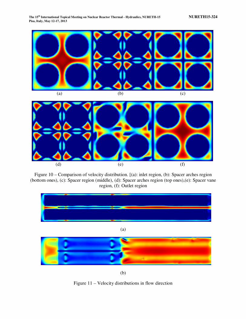
Figure (10) and (11) presents comparison of velocity counters in lateral and longitudinal
directions respectively. From figures, it can be realized that lattice resolutions are sufficient for
this problem. The code can resolve the tiny structures of spacer grid such as arches. Also, the
effects of vanes are seen from Figure 10(e). Flow pattern changed in vane regions.
Figure 9 – Vertical velocity distribution near central region
The 15th International Topical Meeting on Nuclear Reactor Thermal - Hydraulics, NURETH-15 NURETH15-324 Pisa, Italy, May 12-17, 2013
(a) (b) (c)
(d) (e) (f)
Figure 10 – Comparison of velocity distribution. [(a): inlet region, (b): Spacer arches region
(bottom ones), (c): Spacer region (middle), (d): Spacer arches region (top ones),(e): Spacer vane
region, (f): Outlet region
(a)
(b)
Figure 11 – Velocity distributions in flow direction
The 15th International Topical Meeting on Nuclear Reactor Thermal - Hydraulics, NURETH-15 NURETH15-324 Pisa, Italy, May 12-17, 2013
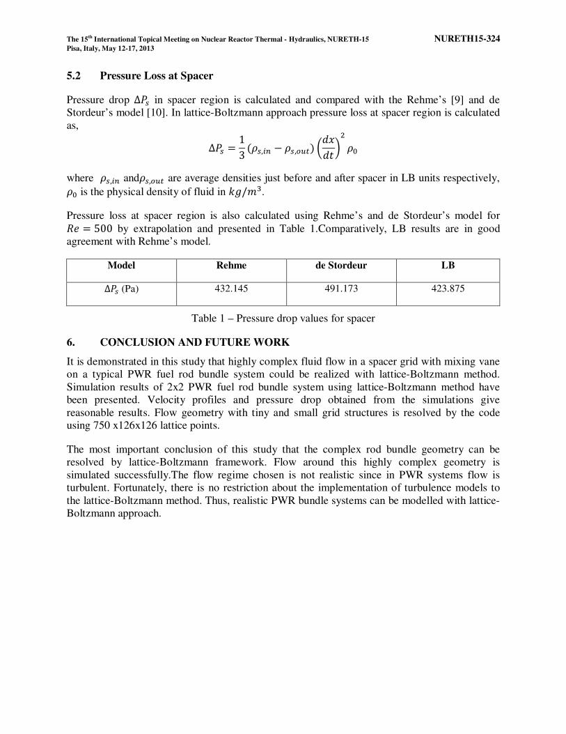
5.2 Pressure Loss at Spacer
Pressure drop ∆W. in spacer region is calculated and compared with the Rehme’s [9] and de
Stordeur’s model [10]. In lattice-Boltzmann approach pressure loss at spacer region is calculated
as,
∆W. = 13 �#.,KX − #.,�Y>� 1ZZ 2( #7
where #.,KX and#.,�Y> are average densities just before and after spacer in LB units respectively, #7 is the physical density of fluid in RS/PT.
Pressure loss at spacer region is also calculated using Rehme’s and de Stordeur’s model for G� = 500 by extrapolation and presented in Table 1.Comparatively, LB results are in good
agreement with Rehme’s model.
Model Rehme de Stordeur LB
∆W. (Pa) 432.145 491.173 423.875
Table 1 – Pressure drop values for spacer
6. CONCLUSION AND FUTURE WORK
It is demonstrated in this study that highly complex fluid flow in a spacer grid with mixing vane
on a typical PWR fuel rod bundle system could be realized with lattice-Boltzmann method.
Simulation results of 2x2 PWR fuel rod bundle system using lattice-Boltzmann method have
been presented. Velocity profiles and pressure drop obtained from the simulations give
reasonable results. Flow geometry with tiny and small grid structures is resolved by the code
using 750 x126x126 lattice points.
The most important conclusion of this study that the complex rod bundle geometry can be
resolved by lattice-Boltzmann framework. Flow around this highly complex geometry is
simulated successfully.The flow regime chosen is not realistic since in PWR systems flow is
turbulent. Fortunately, there is no restriction about the implementation of turbulence models to
the lattice-Boltzmann method. Thus, realistic PWR bundle systems can be modelled with lattice-
Boltzmann approach.

The 15th International Topical Meeting on Nuclear Reactor Thermal - Hydraulics, NURETH-15 NURETH15-324 Pisa, Italy, May 12-17, 2013
7. REFERENCES
[1] D.O.E.Elvis, Y.A. Hassan, “Non-intrusive experimental investigation of flow behaviour
inside a 5x5 rod bundle with spacer grids using PIV and MIR”, Nuclear Engineering and
Design , Vol.239, No.5, 2009, pp. 888-898
[2] S. Jafari,M. Salmanzadeh,M. Rahnama,G. Ahmadi,“Investigation of particle dispersion
and deposition in a channel with a square cylinder obstruction using the lattice Boltzmann
method”, Journal of Aerosol Science, Vol. 41, 2010, pp.198–206
[3] M. Stiebler, M. Krafczyk., S. Freudiger, M. Geiger, “Lattice-Boltzmannlarge eddy
simulation of subcritical flows around asphere on non-uniform grids”, Mesoscopic
Methods for Engineering and Science, Vol.61, No.12,2009, pp. 3476-3484
[4] J. Latt, Choice of units in lattice Boltzmann simulations, 2008, accessed 29 November
2012, <http://wiki.palabos.org/_media/howtos:lbunits.pdf>
[5] H. Ganjiani, B. Firoozabadi,“Three-Dimensional Simulation of Turbulent Flow in 3-Sub
Channels of a VVER-1000 Reactor”, Transaction B: Mechanical Engineering, 2010, Vol.
17, No.2, pp. 83-92
[6] M. Gustzav, P. Jozsef, H. Gabor, “Large eddy simulation of subchannels using the lattice
Boltzmann method”,Annals of Nuclear Energy, Vol.34, No. 1-2, 2007, pp. 140–149
[7] M.C. Sukop, D.T. Thorne, Lattice Boltzmann modelling: an introduction for geoscientists
and engineers, Springer-Verlag, ISBN-13 978-3-540-27981-5, 2005
[8] P.L. Bhatnagar, E.P. Gross, M. Krook, “A model for collisional processes in gases. I.
small amplitude processes in charged and in nutral one-component systems”, Physical
Review, Vol.94, No. 3, 1954, pp. 511-525.
[9] N.E. Todreas, M.S. Kazimi, Nuclear Systems I-Thermal Hydraulic Fundamentals, Taylor
& Francis, ISBN 1-56032-051-6, 1993
[10] A. N. de Stordeur,"Drag Coefficients for Fuel Element Spacer" Nucleonics, Vol.19, No.6,
1961, pp.746-789.
[11] K. Rehme, "Pressure Drop Correlations for Fuel Element Spacers" Nuclear Technology,
Vol.17, 1973, pp. 15-23.