simulation software for the analysis of electrical power ...€¦ · 13.08.2013 simsen:history,...
TRANSCRIPT

13.08.2013
Simulation software for the analysis of electrical power networks,adjustable speed drives and hydraulic systems
EPFL, Swiss Federal Institute of TechnologyCH-1015 Lausanne, Switzerland.
[email protected] version available on the website: http://simsen.epfl.ch
Main features• Graphical input/output• Modular structure with arbitrary topology• No restriction on the network size• Events detection and back-tracking• Load-Flow calculation• Initial conditions entirely, partly or not defined• Stable operating point entirely saved• Interactive read/write access to any parameter• Harmonics analysis• Parameterization• SI or per unit outputs• Available tutorials and help-on-line• Runs under Windows XP/Windows7/32/64bits
Electrical Power Networks• Electrical machines• Electromagnetic transients in AC/DC networks• Transient stability and general fault analysis• SubSynchronous Resonance (SSR)• Torsional analysis• FACTS, HVDC, SVC• Control and regulation• IEEE Standard excitation systems and PSS
Adjustable Speed Drives• Special machines• Power electronics converters• Cyclo-converters• Voltage Source Inverters (VSI)• Analog / digital mixed signals
simulation• Control and regulation
Regulation part• Easy definition of regulation structures• Programmable unit, logical table• S-transfer functions, regulator• Digital devices, Z-transfer functions• Control devices, ON-LINE FFT• User defined DLL for control• Coupling with MATLAB• Coupling with external application (Labview,
Hardware, etc)
Hydraulic systems• Water hammer calculation• Turbines 4 quadrants transient behavior• Francis/Pelton/Kaplan and pump-turbines• Pumps • Surge tanks, surge shafts, differential ST• PID Turbine governors• Hydroelectric interactions• Tidal turbines• Cavitation/Water column separation

13.08.2013
SIMSEN: History, Users / Partners
A modular software package for the digital simulation and analysis of power networks and adjustable speed drives
SIMSEN History and development:
The development of this software started in 1992. The idea was to develop a modularsystem able to do fast simulations of electrical power systems including semiconductorsand regulation parts. The whole development has been based on practical examples frompower networks and industrial drives. In both domains, the customer came with problemsrequiring the study of complex systems. In 1994, it was decided do develop aninput/output interface. Thus other people could use the system. SIMSEN is sold since1996. From 1996 to 1998, the system has been extended to simulate the digital behaviorof the regulation part. The present version is able to simulate correctly mixed-signalssystems (systems with analog and digital elements). Results provided by SIMSEN havebeen validated by comparison with measurements in industrial projects. Since 2001,SIMSEN is extended to hydraulic components for the modeling of hydraulic installationsand of entire hydroelectric power plants: SIMSEN-Hydro.
SIMSEN Users / Partners:
ALSTOM Power Generation Ltd., Birr, Switzerland, Hydropower generation: on site world wide license
ALSTOM Power Generation Ltd., Birr, Switzerland, Turbo generators
ALSTOM Power Conversion Ltd., Belfort, France: Power Electronics and Adjustable Speed Drives
ABB Industry, Turgi, Switzerland, Power Electronics and Adjustable Speed Drives: on site Swiss license
ABB Industri AS Norway: Power Electronics and Adjustable Speed Drives
ABB (China) Ltd, Shanghai Branch, Shanghai, China
ABB Pte Ltd, Singapore
ALSTOM Hydro France Ltd., Grenoble, France
VOITH Hydro Holding GmbH, Heidenheim, Germany : on site world wide license
ANDRITZ Hydro AG, Switzerland, Austria
Litostroj Power d.o.o, Ljubljana, Slovenia
IMPSA Hydro, Mendoza, Argentina
Vetco Gray, Billingstad, Norway
ANSALDO Energia s.p.a. Italy : Power generation
WEIDMANN Transformer board AG, Rapperswil, Switzerland
Utilities: EOS, BKW, GROUPE E, SEL, SIG
AF-Consult Switzerland Ltd., Baden, Switzerland
Tractebel Eng. Coyne et Bellier, Gennevilliers, France
Lombardi Ltd, Minusio, Switzerland
Hydro Exploitation, Sion, Switzerland
IM Ingegneria Maggia SA, Locarno, Switzerland
ISL Ingénierie, Lyon, France
Power Vision Engineering sàrl, Ecublens, Switzerland
Hidroinstitut, Ljubljana, Slovenia
EDF-CIH, Le Bourget-du-Lac, France

13.08.2013
SIMSEN-Electro: Presentation
Electrical systems simulation features of SIMSEN :
• Mixed analog-digital simulation of electrical systems.
• Modular structure enabling simulations of power systems with arbitrary topology in transient or steady-stateconditions.
• Parameterization of components and modularity enables to built complex sub-models of new components.
• Analysis of the dynamic behavior of complex electrical systems comprising electrical machines, power electronicsconverters and typical power system components (transmission line,..)
• Calculation of stable initial conditions with load-flow procedure.
• Possibility to interact with external programs or devices
• Has been validated by comparison with measurement on many industrial cases.
• Example of application: HVDC system, fault recovery after short circuit on the AC grid
• Voltage and current at the DC-link level during the fault
• Currents on the AC grid during recovery
• Control of the rectifier

13.08.2013
SIMSEN-Electro: List of available units
Electrical machines
Three-phase synchronous, single-phase synchronous,6-phase synchronous, three-phase generalized,three-phase induction with wound rotor, three-phaseinduction with squirrel cage rotor, two-phase induction,three-phase permanent magnet, DC motor,mechanical mass, stator mass
Three-phase elements
Voltage supply, transmission lines,circuit breaker, phase shifting transformer, transformer with three windings, load
Three-phase converters
Rectifier (diode), current converter (thyristor), voltage inverter (thyristor GTO), current variator (thyristor)
Single-phase elements
Voltage supply, Resistor, inductor, capacitor, varistor,circuit breaker, linked inductor, transformer
Semiconductors
Diode, thyristor, thyristor GTO, thyristor GTO + diode, triac, IGBT
Analog function units
Program, S-transfer functions, regulator, logical table, points function, external DLL
Digital function units
Averager, sample, limiter, pulse generator, Z-transfer function, hysteresis, on-line FFT

13.08.2013
SIMSEN-Hydro: Presentation
Hydraulic Extension of SIMSEN :
• Modeling of hydraulic components based on electrical analogy.
• Based on a modular structure enabling digital simulations of the behavior in transient or steady-state conditions ofentire hydroelectric power plant with arbitrary topology.
• One set of differential equations including hydraulic components, mechanical masses, electrical units and controldevices ensures that the hydroelectric interactions are properly taken into account.
• Parameterization of components and modularity enables to built up complex sub-models of new components.
• Analysis of dynamic behavior of complex piping systems.
• Example of application: total load rejection of a 2 Francis turbine units power plant
• Out of phase synchronization of unit 1…
… Effects on unit 2
Surge tank transients
Unit 1 transients

13.08.2013
SIMSEN-Hydro: List of available units
Hydraulic Extension of SIMSEN :
Hydraulic Units:
• Reservoir
• Pipe
• Viscoelastic Pipe
• Valves
• Discrete Losses
• Surge Tank, Surge Shaft, Surge Vessel
• Air vessel
• Cavitation Compliance with Mass Flow Gain Factor
• Pressure Sources
• Pumps
• Francis Pump-Turbine
• Pelton Turbine
• Kaplan Turbine
• Propoeller turbines
Turbine models based on turbine characteristics
Pipe model based on electrical equivalent
Momentum and mass conservationequations provide a set of hyperbolicpartial differential equations solved byfinite difference method using centeredand Lax scheme leading to an equivalentelectrical circuit modeling a pipe oflength dx. The capacitance, inductanceand resistance respectively accounts forcompressibility, inertia and losses effects.

13.08.2013
SIMSEN: New features of version 2.2.10
New features of SIMSEN :
• Calculation speed improvement (at least 2 times faster).
• Equations parser in main file and in new unit PROG.
• ON-LINE Fast Fourier Transform (FFT)
• User defined DLL for control (C++, PASCAL, etc…)
• New output interface VISUAL 2.2
• Synchronous machine parameters conversion from characteristic quantities
to equivalent circuit diagram

13.08.2013
SIMSEN: New features of version 2.3
New features of SIMSEN :
• Editing of large files
• New types of voltage regulators for ALSTOM POWER GENERATION
• Batch processes for background simulations
• Variable coupling coefficient of linked inductors
• New output interface VISUAL 2.4
• Induction machine parameters conversion to per unit equivalent circuit diagram
13.08.2013
SIMSEN: Ongoing and future developments
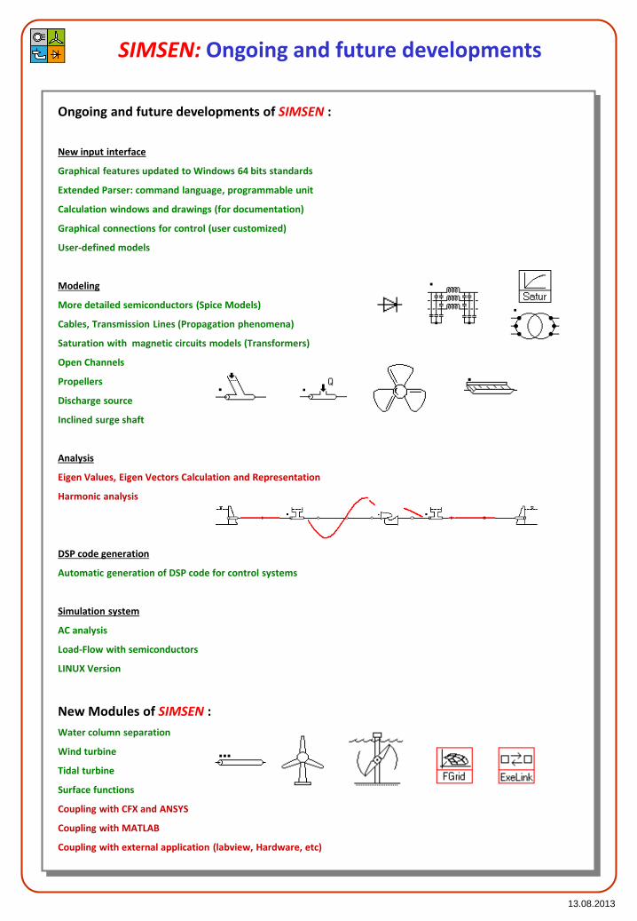
Ongoing and future developments of SIMSEN :
New input interface
Graphical features updated to Windows 64 bits standards
Extended Parser: command language, programmable unit
Calculation windows and drawings (for documentation)
Graphical connections for control (user customized)
User-defined models
Modeling
More detailed semiconductors (Spice Models)
Cables, Transmission Lines (Propagation phenomena)
Saturation with magnetic circuits models (Transformers)
Open Channels
Propellers
Discharge source
Inclined surge shaft
Analysis
Eigen Values, Eigen Vectors Calculation and Representation
Harmonic analysis
DSP code generation
Automatic generation of DSP code for control systems
Simulation system
AC analysis
Load-Flow with semiconductors
LINUX Version
New Modules of SIMSEN :
Water column separation
Wind turbine
Tidal turbine
Surface functions
Coupling with CFX and ANSYS
Coupling with MATLAB
Coupling with external application (labview, Hardware, etc)

13.08.2013
SIMSEN-Electro: SubSynchronous Resonance (SSR)
This example shows the possibilities ofSIMSEN to take into account correctly theelectrical and mechanical interactions inpower systems. The SubSynchronousResonance (SSR) is an important problem incompensated power networks. Due to achange of topology or impedance of thecompensated network, electrical resonancemay match the mechanical resonance in theshaft of large generators. Such a resonancemay destroy the whole shaft of generators.
The example is based on an IEEE paper aboutSSR. The main goal of this simulation is tocheck the computed results with analyticalinvestigations. Additionally, the simulationhas been compared with a specific programdeveloped only to analyze SSR. SIMSEN andthe special program gave exactly the sameresults.
The black curve presents the resultsobtain by a specific program developed toanalyze SSR problems.

13.08.2013
SIMSEN-Electro: Back to back start-up
The back to back start-up ofsynchronous machines is a verysuitable procedure to startsmoothly a synchronous motor inpump operating mode with the helpof a second synchronous generatordriven by a turbine. The generatorworks like a variable frequencyvoltage supply. Both machines haveto be connected through atransmission line. SIMSEN is alsoable to simulate a directasynchronous start-up.
Both machines are excited at standstill witha specified field current depending on theoperating mode (generator or motor). Thegenerator is accelerated by the mechanicaltorque of the turbine. The voltageincreases as well as the frequency at theterminals of the generator. The excitedrotor of the motor follows the rotating fieldand get synchronized after someoscillations due to its initial positionrelative to the poles wheel.
The above curves represent the speed ofboth synchronous machines. The pumpfriction torque also has been taken intoaccount. The mechanical driven torque ofthe turbine is kept constant.
The 2 last figures represent the air-gaptorque of both synchronous machines aswell as their field currents. Depending onthe rotor positions and field currents, theback-to-back start-up may fail.
13.08.2013
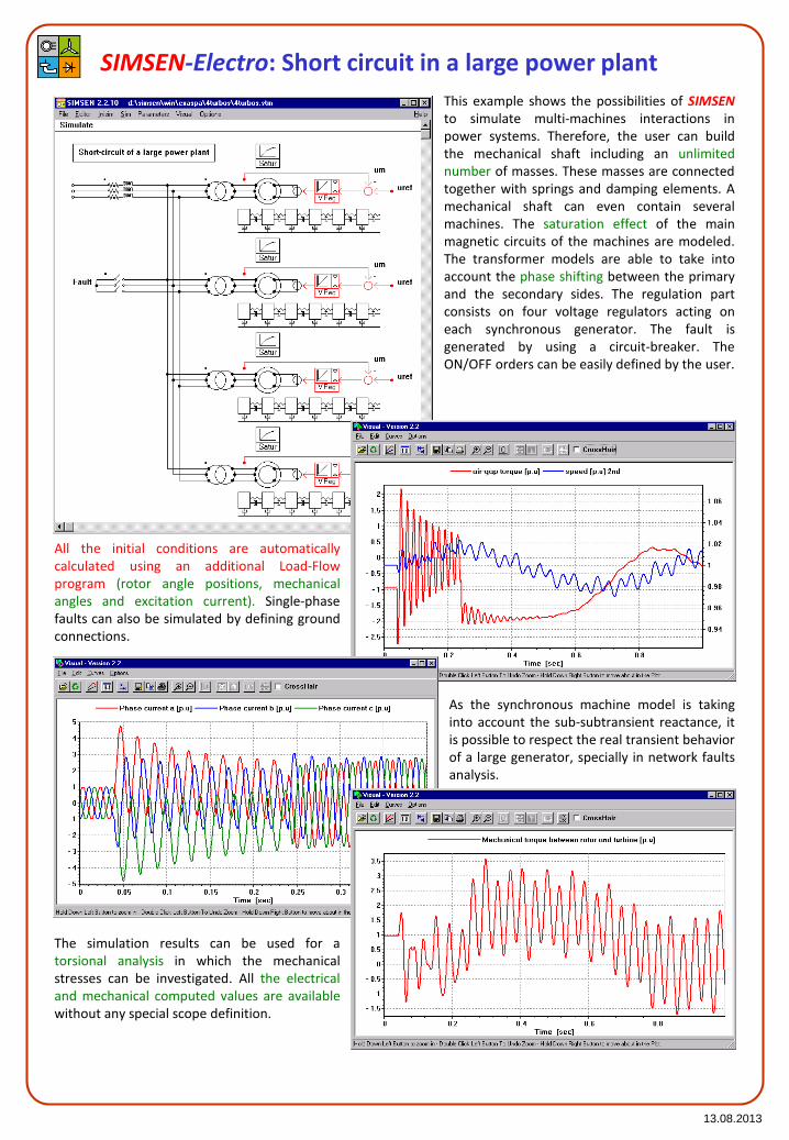
This example shows the possibilities of SIMSENto simulate multi-machines interactions inpower systems. Therefore, the user can buildthe mechanical shaft including an unlimitednumber of masses. These masses are connectedtogether with springs and damping elements. Amechanical shaft can even contain severalmachines. The saturation effect of the mainmagnetic circuits of the machines are modeled.The transformer models are able to take intoaccount the phase shifting between the primaryand the secondary sides. The regulation partconsists on four voltage regulators acting oneach synchronous generator. The fault isgenerated by using a circuit-breaker. TheON/OFF orders can be easily defined by the user.
All the initial conditions are automaticallycalculated using an additional Load-Flowprogram (rotor angle positions, mechanicalangles and excitation current). Single-phasefaults can also be simulated by defining groundconnections.
The simulation results can be used for atorsional analysis in which the mechanicalstresses can be investigated. All the electricaland mechanical computed values are availablewithout any special scope definition.
SIMSEN-Electro: Short circuit in a large power plant
As the synchronous machine model is takinginto account the sub-subtransient reactance, itis possible to respect the real transient behaviorof a large generator, specially in network faultsanalysis.

13.08.2013
This example illustrates the potential ofSIMSEN to simulate large power networks (Norestriction on the network size). Theadditional Load-Flow program calculatesautomatically all the initial conditions (Phasecurrents, field currents and rotor positions ofsynchronous machines). The results can beused to determine the transient stability ofthe entire network.
SIMSEN-Electro: Transient stability in a large power network
The simulation results show the transientbehavior of a large 465 MVA hydro-generatorafter a three-phase short-circuit on a 400 kVtransmission line. All the results for all theelements present in the network can be savedand analyzed after the computation. TheLoad-Flow operating point has been comparedsuccessfully with measurements.

13.08.2013
This example illustrates thepossibility of SIMSEN tosimulate complex HVDCnetworks including powerplants, 12-pulse thyristorsconverters, filters, SVC and allthe control and regulationdevices. Both rectifier andinverter of the HVDC aremodeled with all thesemiconductors. Three -windings transformers also aretaken into account on bothsides of the HVDC. They allowthe 30° phase shifting for 12-pulse operation.
For large and complex networks, SIMSEN offersthe possibility to add, replace or removecomponents without restarting the simulationfrom zero. This great advantage allows the studyof networks including a large number of electricalcomponents. The user can build his example stepby step by adding elements and restabilizing thecircuit.
When the system is stable enough, the user canadd circuit breakers (or other elements) anddefine faults to be simulated. Once done, it ispossible to continue the simulation with savedinitial conditions. For that special example, it ispossible to analyze the fault recovery after ashort circuit at the rectifier AC grid. In this goal,the regulation contains special functions likeVDCOL (Voltage Dependant Current OrderLimitation). This functions allow a smoothrecovery of the HVDC.
SIMSEN-Electro: HVDC network with SVC
The rectifier and inverter regulation is completelymodeled, especially the extinguishing angleregulation of the inverter. Simulation resultsshow the behavior of the HVDC after a three-phase short circuit at the rectifier AC grid (powerplants).

13.08.2013
SIMSEN-Electro: Three-level Voltage Source Inverter (VSI)
This example is based on a real industrialapplication in the field of Medium VoltageDrives (MVD). It is very important tosimulate correctly the three-level inverterwith all the semiconductors. The inverter istuned by a Direct Torque Control (DTC).The entire regulation has beenimplemented taking into account the realdigital behavior.
The entire system has been modeledusing more than 200 units to simulatecorrectly the flux estimation, the DTCwith multi-level hysteresis control, theswitching frequency control, speedcontrol. This example shows the potentialof SIMSEN to simulate mixed signals.Simulation results present the stepresponse behavior of the drive.
t__inv_ref, t__inv, t__sta, u__dc [p.u.]
-0.2
0
0.2
0.4
0.6
0.8
1
1.2
1.4
0 0.005 0.01 0.015 0.02 0.025 0.03 0.035 0.04 0.045 0.05
Time [s]
Measurements

13.08.2013
SIMSEN-Electro: Slip-energy recovery drive VARSPEED
This example shows a large pumpstorage system called VARSPEED. Theinduction machine is supplied by a 12-pulse cyclo-converter. The 72 thyristorsare considered without anyassumptions. Such a system is able toregulate active and reactive powerindependently. The drive can work aspower generation as well as pump.
The simulation illustrates the response ofthe motor/generator after a suddenmodification of the reactive powerinjected to the AC grid. It also shows thehigh stability of the VARSPEED in transientbehavior. Many other aspects can beanalyzed with SIMSEN: faults andprotection, stability to the network,efficiency.

13.08.2013
SIMSEN-Electro: 12-pulse Load Commutated Inverter (LCI)
This example presents a largeindustrial adjustable speeddrive. The Load Com-mutatedInverter (LCI) is supplying largesynchronous machines having 6phases. Thus, the 6th harmonicof the air-gap torque is automa-tically eliminated by the 12pulse inverter. The system istaking into account all theregulation parts, the 6-phasesynchronous machine, themechanical shaft and thefrequency converter. Themechanical load corresponds toa 20 MW fan for wind tunnelapplications.
The simulation results show the responseof the system after a change of the speedset value. The load represents a large fanand has been modeled with a squarefunction of the speed. The simulation hasbeen used to perform a torsional analysisand to design the inverter in function of theextinguishing angle of the inverter at fullload.
Results have been compared successfullywith a real 20 MW drive. The displayedcurves presents the stator currents and thefield current, the air-gap torque and motorspeed, the voltage and current on athyristor valve.
The 6-phase synchronous machine modelhas been especially developed for suchkind of drives using 12-pulse converters.
13.08.2013
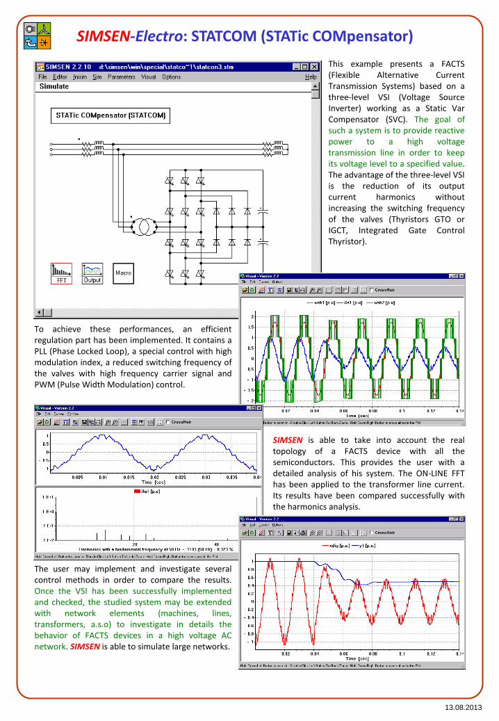
SIMSEN-Electro: STATCOM (STATic COMpensator)
This example presents a FACTS(Flexible Alternative CurrentTransmission Systems) based on athree-level VSI (Voltage SourceInverter) working as a Static VarCompensator (SVC). The goal ofsuch a system is to provide reactivepower to a high voltagetransmission line in order to keepits voltage level to a specified value.The advantage of the three-level VSIis the reduction of its outputcurrent harmonics withoutincreasing the switching frequencyof the valves (Thyristors GTO orIGCT, Integrated Gate ControlThyristor).
To achieve these performances, an efficientregulation part has been implemented. It contains aPLL (Phase Locked Loop), a special control with highmodulation index, a reduced switching frequency ofthe valves with high frequency carrier signal andPWM (Pulse Width Modulation) control.
SIMSEN is able to take into account the realtopology of a FACTS device with all thesemiconductors. This provides the user with adetailed analysis of his system. The ON-LINE FFThas been applied to the transformer line current.Its results have been compared successfully withthe harmonics analysis.
The user may implement and investigate severalcontrol methods in order to compare the results.Once the VSI has been successfully implementedand checked, the studied system may be extendedwith network elements (machines, lines,transformers, a.s.o) to investigate in details thebehavior of FACTS devices in a high voltage ACnetwork. SIMSEN is able to simulate large networks.

13.08.2013
SIMSEN-Electro: Multilevel Voltage Source Inverter
This example presents a multi levelVoltage Source Inverter (VSI)supplying an induction motor. Formedium voltage drive applications,the proposed topology has theadvantage of reducing the voltageharmonics on the motor using a multilevel inverter. Each cell of theinverter is supplied by a small DCvoltage. It is possible with the seriesconnected cells to provide the motorwith the desired phase voltage. Theonly inconvenient is the input supplytransformer that needs manysecondary windings as shown on thefigure. This transformer has beenmodeled in details with linkedinductors taking into account thespecial phase shifting angle of eachsecondary winding as well as theshort circuit reactance of thetransformer. This exampledemonstrates that SIMSEN canmaster a large number ofsemiconductors
Figures show experimental results (black) andsimulation results (color). One may notice the 18 pulsebehavior on the input of the drive due to the specialtransformer. The control applied is based on PWMcontrol with shifted carrier signals.
Measurements
Measurements

13.08.2013
SIMSEN-Electro: 3-level UPFC (Unified Power Flow Controller)
This example presents a 3-levelUPFC (Unified Power FlowController). It concists of two 3-level VSI (Voltage SourceInverter) connected to the sameDC-link. The first VSI is shuntconnected to the AC bus. Itworks like a STATCOM in orderto maintain the voltage on theAC node. The second VSI is serialconnected to the transmissionline. It can insert a regulatedserial voltage in the transmissionline.
Inserting this serial voltage in the transmissionline, it is possible to modify the relativeimpedance of the transmission line, and thus torequire the transmitted active and reactivepower independently. The AC bus voltagemaintain is also a great advantage of the UPFC.
The curves represent a step response of activeand reactive power in the transmission line. It isimpressive to observe the high dynamic of theregulation even in such a case of high powerUPFC (160 MVA, 6 kV DC, 50 Hz). The current inthe transmission line contains only fewharmonics (THD < 2%).
Again, this example shows the potential ofSIMSEN to simulate in details power systemsincluding power electronics devices. Suchpower network studies are going to be moreand more important in the future. It isessential to take into account the powerelements with three-phase modeling and thecomplete regulation in order to perform aright harmonics analysis.

13.08.2013
SIMSEN-Electro: Doubly-fed induction motor/generator with 3-level VSI
This example presents aDoubly-fed AsynchronousMachine (DASM). The rotorcascade is made of 2 3-levelVoltage Source Inverter (VSI)for large pump storage plants.In comparison with thestandard cyclo-convertercascade, the VSI cascaderepresents many advanta-ges:less power components,harmonics reduction, highdynamic and reactive powercompensation.
The whole power circuit as well as the completeregulation part have been implemented inSIMSEN. The control part includes thetransformer control: exchange of active andreactive power, the machine control: speedregulation, stator and rotor current controlsand the DC-link voltages control. Both VSI aretuned with improved PWM shape.
The simulation results present the behavior ofthe system after a 100% single phase voltagedrop at the high voltage side of the maintransformer. SIMSEN appeared to be apowerful simulation system, especially whenreconnecting the cascade transformer to the ACgrid. This allows to estimate correctly the globalpower plant current.
Another important point of the control is therespect of the switching frequency limit of thenew hard-driven GTO’s. This has been takeninto account in the control. Swithingfrequencies of 250 Hz on the transformer side(see beside figure) and 500 Hz on the rotor sidehave been required. Even with these lowswitching frequency values, the calculated THDof both stator and main transformer currentslead to values lower than 1%.

13.08.2013
SIMSEN-Electro: Synchronous motor fed by a 12-pulse cyclo-converter
This example presents asynchronous motor fed bya 12-pulse cyclo-converter.The circuit includes a longtrans-mission line as wellas the harmonics filtersbank. It is possible toanalyze the line-filterinteraction. The 12-pulsecyclo-converter is com-mutated by the ACnetwork. Each DC-linksupplies a phase of thesynchronous motor. Thefield current rectifier is alsotaken into account. Thecontrol scheme is based ona dynamic flux model ofthe synchro-nous machine.It allows a very highdynamic, even if that kindof drive has a very lowsupply frequency.
The simulation results present thebehavior of the system in steady-stateat rated operating point as well as aload change from 50% to 100% atrated speed. SIMSEN is able tosimulate such a complex topology,including more than 210 differentialequations. Values rela-ted to eachsemiconductor can be displayed.
Netwok quantities are also available(active and reactive power, currentharmonics, aso…). The great advantageof SIMSEN in that kind of example isthe possibility to analyze a large powersystem taking into account all thesemiconductors. The influence of eachpower electronics element can beestimated. This feature is a powerfuladvantage to analyze the powersystems of the future, including moreand more power electronics.

13.08.2013
SIMSEN-Electro: Induction motor fed by current converter
This example presents aninduction motor fed by acurrent converter. This is aspecial frequencyconverter including ad-ditional capacitors in orderto extinguish the current ofthe thyristors. This leads tovery fast transients and tothe typical form ofterminal voltages on themotor side. To validate theaccuracy of SIMSEN,measurements have beenrecorded on a real 280 kWdrive.
The results present the behavior of the systemin steady-state at 97% of the rated operatingpoint. The red curves correspond to theSIMSEN computed results and the blue curvesto the measurements. On the right side, theterminal voltage of the motor is displayed.Due to the presence of the extinguishingcapacitors, the voltage presents peaks duringeach commutation. The simulation matchesthe measurements.
On the right side, the air-gap torque isdisplayed. It has been measured through adigital torque measurement device. Thisdevice is based on electrical signals and allowsmeasuring low and high fre-quenciescomponents in the air-gap torque of electricalmachines. The simulation results match themeasurements. This example shows theprecision of the modeling in SIMSEN.
On the left side, the phase currents of themotor are displayed. They present thetypical 120° wave form of the currentconverter. This kind of drive is very sensitiveto the DC link reactor. It is responsible forthe stability of the drive.

13.08.2013
SIMSEN-Hydro: Validation
Example of Validation of SIMSEN-Hydro :
Pumped-Storage Plant (PSP) of 4x400 MW Francis pump-turbines:
• Simulation of emergency shutdown in Generating mode
• Simulation of emergency shutdown in Pumping mode
Turbine mode Pump mode
Load rejection in turbine andpump mode produces massoscillations betweendownstream surge chambersand tailrace reservoir, (top),waterhammer effects in thedraft tube, (middle), and in thepenstock (bottom).Comparisons betweenexperiments (black) andsimulation results obtainedwith SIMSEN-Hydro (red) showgood agreements for bothoperating mode: generatingand pumping mode. Thesimulation also providesrunaway speed of the units.

13.08.2013
SIMSEN-Hydro: Hydroelectric transients
Example with SIMSEN-Hydro :
Tripping of a 200 MW consumer load in an islanded power network comprising:
• 1 GW Hydroelectric power plant including 4x250 MW Francis turbines, long penstock and surge tank
• 1 to 4 thermal power plants of 1.3 GW including, high pressure, 2 low pressure steam turbines
• Passive consumer loads
• Transmission line of 400 kV
P50%
P27%
P20%
P16%
P50%
P27%
P20%
P16%
P∞
Connection to islanded power networkinduces stabilization effects for lowfrequencies dependant on network powerlevel and points out generator naturalfrequency for 1.36 Hz
• Turbine transfer function without connection to the islanded power network
• Turbine transfer function with connection to the islanded power network
• Unstable operation when the generator natural frequency is not considered for the turbine speed governor parameters selection
• and stable operation when considered, with influence of network power level

13.08.2013
SIMSEN-Hydro: Hydroelectric transients with Power System Stabilizers (PSS)
Example with SIMSEN-Hydro :
Tripping of a 200 MW consumer load in an islanded power network comprising:
• 1 GW Hydroelectric power plant including 4x250 MW Francis turbines, long penstock and surge tank
• 1 to 4 thermal power plants of 1.3 GW including, high pressure, 2 low pressure steam turbines
• Passive consumer loads
• Transmission line of 400 kV
Speed deviations and poweroscillations can be considerablyreduced using Power SystemStabilizers, PSS.
The IEEE PSS2B has for inlet valuesthe network frequency deviationand the electrical active power, theoutput value is a correction of thevoltage regulator set point.
• Stabilization of active power with and without PSS
• Reduction of speed deviation obtained with Power System Stabilizer IEEE PSS2B
• Block diagram structure of the IEEE PSS2B Power System Stabilizer

13.08.2013
SIMSEN-Hydro: Power plant full load instabilities
Hydroelectric example with SIMSEN-Hydro :
Power plant model including:• penstock• 4 x 400 MW Francis pump-turbines• full load vortex rope model• downstream surge chambers• tailrace tunnel• rotating inertias• synchronous generators• transformers• infinite network• voltage regulators
• Full load vortex rope modeled by cavitation compliance C and mass flow gain factor C
2 21 2
dH dQQ Q C
dt dt− = + Investigation:
Full load instabilities in generating mode areinduced on unit 4 by the shutdown of the unit 2which decreases downstream water level, andthus the cavitation number.
Indeed, non-linear behavior of the cavitationvortex rope compliance is taken into account forthis investigation enabling the explanation ofinstabilities onset for this pumped-storage plant.
Pressure fluctuations in spiral case and drafttube, as well as characteristics frequencies arewell simulated.
• Pressure fluctuations at unit 4 spiral casing and draft tube
• Active and reactive power of unit 4• Unit 2 normal shutdown

13.08.2013
SIMSEN-Hydro: Pumped-Storage Plant
Hydraulic transient of complex pumped-storage plant with SIMSEN-Hydro :
Power plant model including:• 2 reservoirs• 2 galleries• 2 surge chambers• 2 penstocks• 3 x 25 MW Pelton Units• 1 x 25 MW pump• 1 x Siphon pump
Investigation:The pumped-storage power plant comprises 3 units:
- Unit 1: with Pelton turbine and siphon driven by thesame synchronous generator all on the same shaftline;- Unit 2: with Pelton turbine and storage pump drivenby the same generator on the same shaft line;- Unit 3: with Pelton turbine only.
There is more than 60 different operatingconfigurations.
Thus, complex emergencyshutdown procedures inturbine and pump modes aresimulated to definemaximum power plantsolicitations.
Discharge pump [m3/s]Discharge siphon pump [m3/s]Total discharge [m3/s]
Discharge Pelton unit 2 [m3/s]Head in penstock (2nd) [mWC]
• Discharge in Pelton turbine and Pump ofUnit 2 and Siphon pump during pumpemergency shutdown with Pelton nozzleopenings to avoid reverse pumping
• Penstock head for differentreservoir water level settingsresulting from 3 units emergencyshutdown

13.08.2013
SIMSEN-Hydro: Hydraulic test rig resonance
Example of Validation of SIMSEN-Hydro :
Modelling of Francis turbine scaled model testrig with SIMSEN-Hydro to explain vortex ropeinduced resonance of the hydraulic circuit.
The closed loop test rig model includes themodel of the downstream tank, the parallelpumps, the piping system, the turbine and thedraft tube.
The draft tube model is modeled with 2 pipesand a pressure source. Free and forcedoscillations are preformed.
• Free oscillation analysis: based on PRBS excitation (PRBS: Pseudo Random binary Sequence)
• Water fall diagram of the pressure pulsations resulting from free oscillation analysis
• Forced response analysis: Pressure source excitation modeling vortex rope excitation
• Water fall diagram of the pressure pulsations resulting from forced oscillation analysis
• Comparison of pressure amplitude spectra at pressure source and turbine cone in the case of forced response analysis showing good agreements for the characteristic frequencies

13.08.2013
SIMSEN-Hydro: Transient of Variable Speed Pump-Turbine Unit
Transient of variable speed pump-turbine with SIMSEN-Hydro :
• 2x320MW Variable Speed Pump-Turbine Power Plant
A 2x320 MW Pumped-Storage plant ismodeled with SIMSEN and includes:- Hydraulic circuit- Pump-turbine- Doubly Fed Induction Generator (DFIG) with 3 levels Voltage Source Inverter (VSI)
- Infinite power network
Variable speed advantages:- Possibility of active power controlin pumping mode
- Efficiency increase and widerange of operation in generatingmode especially under partialload
- Network stability improvementby reactive power control
- Network stability improvementby instantaneous power injectionin the grid « Flywheel Effect»
- Starting of the group in pumpingmode without supplementaryequipment
• Control strategy in turbine mode of operation
Turbine mode Pumping mode
Fast
act
ive
po
wer
ad
just
men
tP
um
p-t
urb
ine
tran
sien
t
• Turbine speed governor
• Variable speed unit transient resulting from power setpoint change

13.08.2013
SIMSEN-Hydro: Pumped-Storage Plant in Mixed Islanded Power Network
Modeling of mixed islanded power network with SIMSEN-Hydro :
A mixed islanded power network ismodeled with SIMSEN and includes:- 2x250 MW Pumped-Storage plant- 100x2 MW = 200 MW Wind Farm- 1300 MW Thermal Power Plant- Passive consumer load.
Pumped-Storage Plant modelThe Pumped-storage plant is made of:- upstream reservoir;- gallery;- penstock;- 3 type-machine unit with Francis turbine, generator, fluid coupling and pump on the
same shaft line (3 inertias model);- tailrace water tunnel;
Thermal Power Plant modelThe thermal power plant modelincludes:- upstream steam pressurized tank;
- high pressure steam turbine;- re-heater;- 2 low pressure steam turbines;- and a 4 inertias shaft line.
Wind Farm modelThe Wind farm model is a 100x2 MWequivalent wind turbine model,comprising:- wind model;- shaft line model with shaft stiffness, turbine and generator inertias and gearbox ratio;
- the wind turbine energy transfer is modeled with a power coefficient Cp as function of the tip speed ratio and blade pitch angle.
• Pumped-Storage plant 2x250 MW with 3 type-machine arrangement
• Thermal power plant 1300 MW
• 100 Wind turbines 2MW

13.08.2013
SIMSEN-Hydro: Pumped-Storage Plant in Mixed Islanded Power Network
Transient of mixed islanded power network with SIMSEN-Hydro :
The 3 type machine unit enables:- adjustable pump power by hydraulicshort-circuit operation;
- rapid pump to turbine operatingmode change-over because of samerotating direction of the pump andthe turbine.
The pump to turbine change-overoperation is simulated considering a windfarm shutdown due to wind over speed.The wind farm power loss is compensatedby the pumped-storage plant.
• The wind turbine power is given by:
0 4 8 12 16 20
Tip Speed Ratio: = Ut/Cinf [-]
0
0.2
0.4
Cp [
-]
0°
1°
2°
5°
10°
15°
20°
25°
35°
50°
3
inf
1
2P Aref Cp C=
21/116( , ) 0.5 0.4 5 i
i
Cp e
− = − −
3
1
1 0.035
0.08 1
i
=
−+ +
1
inf inf2
reftDU
C C
= =
• with the empirical expression of the power coefficient:
• and with the tip speed ratio:
• and the parameter:
• Wind turbine transient during emergency shutdown due to over-speed wind (first, aerodynamic brake with stall control and then circuit beaker tripping):
• Pump shutdown for operating mode change over with clutch decoupling:
• Turbine transient with speed regulator to compensate Wind Farm power loss:
• Power generation during the transient:

13.08.2013
SIMSEN-Hydro: Coupling with CFD computation
Coupling of CFD simulation software with SIMSEN-Hydro :
Complex 3D unsteady hydrodynamic flows are computed using CFD simulation software such as ANSYS-CFX and coupled with SIMSEN hydroacoustic simulations of the hydraulic system
Identification procedure
Q(t)
p(t)a(t), p(t), dV/dQ(t)
SIMSEN
ANSYS-CFX
Cavitating vortex rope in Francis turbines:- 3D unsteady multiphase flow developing in Francis turbine draft tube is simulated with ANSYS-CFXto deduce cavitation compliance and excitation source introduced in 1D SIMSEN simulation- 1D Hydroacoustic hydraulic circuit flows is simulated in SIMSEN and resulting discharge andpressure level are transferred as new boundary conditions in 3D CFD computation
Von Karman vortices induced pipe resonance:- 3D unsteady flow developing behind a bluff body in pipe is simulated with ANSYS-CFX to deducepressure excitation source then introduced in 1D SIMSEN simulation- 1D Hydroacoustic pipe flows is simulated in SIMSEN and resulting discharge and pressure level aretransferred as new boundary conditions in 3D CFD computation

13.08.2013
SIMSEN Users and Partners
Ecole Polytechnique Fédérale de LausanneCH-1015 LausanneSwitzerlandhttp://[email protected]
Power Vision Engineering SàrlCh. Des Champs-Courbes 1
CH-1024 EcublensSwitzerland
http://[email protected]
Demo version available on: http://simsen.epfl.ch
SIMSEN Contacts
For distribution, support and trainings:
HIDROINŠTI
TUT