simulation study on braided hose failure in major ...utpedia.utp.edu.my/15676/1/simulation study on...
TRANSCRIPT

Simulation Study on Braided Hose Failure in Major Equipment at PETRONAS Carigali Sdn Bhd (PCSB)
by
Eleena Aqmal Binti Ab Rahim
14803
Dissertation submitted in partial fulfilment of
the requirements for the
Bachelor of Engineering (Hons)
(Mechanical)
JANUARY 2015
Universiti Teknologi PETRONAS
Bandar Seri Iskandar
31750 Tronoh
Perak Darul Ridzuan

i
CERTIFICATION OF APPROVAL
Simulation Study on Braided Hose Failure in Major Equipment at PETRONAS
Carigali Sdn Bhd (PCSB)
by
Eleena Aqmal Binti Ab Rahim
14803
A project dissertation submitted to the
Mechanical Engineering Programme
Universiti Teknologi PETRONAS
in partial fulfilment of the requirement for the
BACHELOR OF ENGINEERING (Hons)
(MECHANICAL)
Approved by,
____________________________
(Ir. Dr. SUHAIMI BIN HASSAN)
UNIVERSITI TEKNOLOGI PETRONAS
TRONOH, PERAK
January 2015

ii
CERTIFICATION OF ORIGINALITY
This is to certify that I am responsible for the work submitted in this project, that the
original work is my own except as specified in the references and acknowledgements,
and that the original work contained herein have not been undertaken or done by
unspecified sources or persons.
______________________________
ELEENA AQMAL BINTI AB RAHIM

iii
ABSTRACT
In this study, the actual braided hose from Petronas Carigali Sdn Bhd (PCSB) was
obtained in order to investigate the possible causes of failure. The hose is being
assembled with inner tube of polytetrafluroethylene (PTFE) and externally braided
outer tube corrosion-resistant steel (CRES). The actual prototype hose had undergone
failures near the end of the fittings. The actual braided hose measurements were taken
and modelled using SOLIDWORKS software. The ANSYS static structural
stimulation was used to measure the stress distribution on the hose due to pressure
applied with various bend shapes. The simulation was done by fixing the end of the
pipe and exerting force inside the inner layer of PTFE. The results of the simulation
have shown that the braided hose proved high stress near the fittings. Thus, the hose
was unable to stand the pressure exerted, the reasons of failure was identified. Further
analyses were done to the braided hose to investigate the other possible of failure
using failure analysis method. A device was proposed to Petronas Carigali Sdn Bhd
(PCSB) that can earlier detect braided hose failure.

iv
ACKNOWLEDGEMENTS
First and foremost, I would like to express my deepest gratitude to Allah SWT
for His guidance and mercy for the completion and success of my final year project.
Next I would like to thank my supervisor, Ir. Dr. Suhaimi Hassan for his guidance,
advices and discussions that contribute to the success of this project. Without his
support and encouragement, I could not have gained the experience and knowledge
during this project period.
I would like to give appreciation to my co-supervisor, Dr Tuan Mohammad
Yusoff Shah for his guidance and patience with helping me with the ANSYS software.
With his help and support, I discovered new level of knowledge about Computer
Aided Engineering (CAE) and ANSYS simulation application. This has helped me to
achieve the best results.
I like to take the opportunity to thank Mr M Faizairi B M Nor for his advices
and encouragement to further improve the quality of this project. Lastly, a deep
appreciation to my family for giving me full support to complete this final year
project.

v
TABLE OF CONTENTS
CERTIFICATION OF APPROVAL ............................................................................. i
CERTIFICATION OF ORIGINALITY ....................................................................... ii
ABSTRACT ............................................................................................................... iii
ACKNOWLEDGEMENTS ........................................................................................ iv
LIST OF FIGURES .................................................................................................... vii
LIST OF TABLES ...................................................................................................... ix
CHAPTER 1 INTRODUCTION ................................................................................. ix
1.1 BACKGROUND OF STUDY ............................................................................ 1
1.2 PROBLEM STATEMENT ................................................................................. 2
1.3 OBJECTIVE ....................................................................................................... 3
1.4 SCOPE OF STUDY............................................................................................ 3
1.5 RELEVANCY OF THE PROJECT ................................................................... 4
1.6 FEASIBILITY OF THE PROJECT ................................................................... 4
CHAPTER 2 LITERATURE REVIEW ....................................................................... 5
2.1 INTRODUCTION .............................................................................................. 5
2.1 FAILURE OF HOSE .......................................................................................... 6
2.2 FINITE ELEMENT ANALYSIS (FEA) ............................................................ 9
CHAPTER 3 METHODOLOGY ............................................................................... 11
3.1 PROJECT WORKFLOW ................................................................................. 11
3.2 PROJECT GANTT CHART WITH KEY MILESTONES .............................. 11
3.2.1 Final Year Project 1 ................................................................................... 12
3.2.2 Final Year Project 2 ................................................................................... 13
3.3 BRAIDED HOSE FAILURE ........................................................................... 14
3.4 MEASUREMENT OF BRAIDED HOSE ........................................................ 14
3.5 MATERIAL IDENTIFICATION ..................................................................... 16
3.6 MODELING USING SOLIDWORKS ............................................................. 17
3.7 ANSYS STATIC STRUCTURAL ................................................................... 19
3.7.1 Physical Properties of Solid Geometry ...................................................... 19
3.7.2 Static Structural Geometry Model ............................................................. 20
3.7.3 Meshing in ANSYS Workbench ................................................................ 20
3.7.4 Static Structure Setup ................................................................................. 22

vi
CHAPTER 4 RESULT AND DISCUSSION............................................................. 25
4.1 INTRODUCTION ............................................................................................ 25
4.2 BRAIDED HOSE AT HORIZONTAL INSTALLATION .............................. 25
4.2.1 Von Mises Stress ........................................................................................ 25
4.2.2 Total Deformation ...................................................................................... 27
4.3 BRAIDED HOSE AT U SHAPE INSTALLATION ....................................... 28
4.3.1 Von Mises Stress ........................................................................................ 29
4.3.2 Total Deformation ...................................................................................... 30
4.4 BRAIDED HOSE AT L SHAPE INSTALLATION ........................................ 32
4.4.1 Von Mises Stress ........................................................................................ 32
4.4.2 Total Deformation ...................................................................................... 34
4.5 BRAIDED HOSE AT S SHAPE INSTALLATION ........................................ 35
4.5.1 Von Mises Stress ........................................................................................ 36
4.5.2 Total Deformation ...................................................................................... 37
4.6 DISCUSSION ON ANSYS SIMULATION ANALYSIS ............................... 39
4.7 DISCUSSION ON FAILURE ANALYSIS ..................................................... 40
4.6.1 Failure Modes Effects Analysis (FMEA) .................................................. 40
4.6.2 Fault Tree Analysis (FTA) ......................................................................... 41
CHAPTER 5 CONCLUSION AND RECOMMENDATION ................................... 42
5.1 CONCLUSION ................................................................................................. 42
5.2 RECOMMENDATION .................................................................................... 43
5.2.1 Current Project ........................................................................................... 43
5.2.2 Petronas Carigali Sdn Bhd (PCSB) ............................................................ 44
REFERENCES ........................................................................................................... 45
APPENDIX A ............................................................................................................ 47
APPENDIX B ............................................................................................................. 55

vii
LIST OF FIGURES
Figure 1.1: PVC pipe....................................................................................................2
Figure 1.2: Stripwound hose and corrugated hose........................................................2
Figure 2.1: Failed section of braided hose.....................................................................7
Figure 2.2: Segmenting hose to prevent multi-plane bending.......................................7
Figure 2.3: Maximum normal stress on outside of bend near connector......................8
Figure 2.4: Stress concentration effects of small split increasing normal stress...........9
Figure 3.1: Flowchart of Finite Element Analysis.......................................................9
Figure 3.2: Area of failure near fittings of actual hose...............................................12
Figure 3.3: Braided hose assembly sections...............................................................13
Figure 3.4: Hose section 3..........................................................................................13
Figure 3.5: Hose Section 6..........................................................................................13
Figure 3.6: Cross section of hose fitting......................................................................14
Figure 3.7: Horizontal hose..........................................................................................15
Figure 3.8: U Shape hose.............................................................................................16
Figure 3.9: L Shape hose.............................................................................................16
Figure 3.10: S Shape hose...........................................................................................16
Figure 3.11: Meshing of horizontal hose....................................................................19
Figure 3.13: Meshing of U shape................................................................................19
Figure 3.13: Meshing of L shape hose........................................................................20
Figure 3.14: Meshing of S shape hose........................................................................20
Figure 3.15: Static structural horizontal hose.............................................................21
Figure 3.16: Static structural U shape hose................................................................21
Figure 3.17: Static structural L shape hose.................................................................22
Figure 3.18: Static structural S shape hose.................................................................22
Figure 4.1: Von Mises stress on horizontal hose with full body................................24
Figure 4.2: Von Mises stress on horizontal hose with PTFE......................................24
Figure 4.3: Total deformation on horizontal hose with full body...............................25
Figure 4.4: Total deformation on horizontal hose with PTFE....................................26
Figure 4.5: Von Mises stress on U shape hose with full body....................................27

viii
Figure 4.6: Von Mises stress on U shape hose with PTFE..........................................28
Figure 4.7: Total deformation on U shape hose with full body...................................29
Figure 4.8: Total deformation on U shape hose with PTFE........................................29
Figure 4.9: Von Mises stress on L shape hose with full body.....................................31
Figure 4.10: Von Mises stress on L shape hose with PTFE........................................31
Figure 4.11: Total deformation on L shape hose with full body.................................32
Figure 4.12: Total deformation on L shape hose with PTFE......................................33
Figure 4.13: Von Mises stress on S Shape hose with full body..................................34
Figure 4.14: Von Mises stress on S shape hose with PTFE........................................34
Figure 4.15: Total deformation on S shape hose with full body.................................36
Figure 4.16: Total deformation on S shape hose with PTFE......................................36
Figure 4.17: Fault Tree Analyses (FTA) on Braided Hose Leak................................39

ix
LIST OF TABLES
Table 3.1: Length and diameter of hose section 6 ...........................................................14
Table 3.2: Military coding of braided hose.......................................................................15
Table 3.3: Physical properties of stainless steel and polytetrafluroethylene (PTFE.........18
Table 4.1: Failure Modes Effects Analysis (FMEA) on braided hose failure……...........38

1
CHAPTER 1
INTRODUCTION
1.1 BACKGROUND OF STUDY
A hose is defined as a piece of tubing that is commonly used to move liquids or
gases from one point to another. The shape of the hose is cylindrical which has
circular cross section. The application of hoses is widely used in gardening, fire
fighting, automobile industry and the industrial usage of transporting liquid or gas.
However, in the industrial application, hoses need to withstand a high pressure and
high temperature environment which hoses are made of metal. Generally, the hose
used are stainless steel for corrosion prevention. Numerous applications exist that
require the use of flex hoses. Therefore, a need exists to understand the mechanical
properties and characteristics with great detail before ensuring that a certain flex hose
is appropriate for a given scenario (Pierce & Evans, 2012).
Stainless hose are widely used and common to the plant industry as it has high
physical strength combined with light weight. Besides, the flexible hose are highly
resistance to fire, moisture, abrasion and penetration of external environment. The
tubing of the hose is reinforced with non-rusting metal layer. Hose design depends
on the application when transporting the liquid or gas. Hose can be classified by the
type of service (hydraulic, pneumatic, corrosion-resistant), by material, by pressure,
or by type of construction.
Hoses are classified by types which are non-metallic and metallic. The non-
metallic hose are made of rubber tubing which are using the material of Polyvinyl
chloride (PVC) with various colours as shown in Figure 1.1 (Spellman, 2008). PVC
is light weight, low cost, good mechanical strength, and good mechanical toughness,
resistant to corrosion, easy to install makes it very evident for transporting liquids.

2
Figure 1.1: PVC pipe (source: www.partsbridgeassociate.com)
However, metallic hose are divided into stripwound hose and corrugated
hose. Stripwound hoses consist of spirals that are loosely interlocked as shown in
Figure 1.2. This provides high flexibility due to its profile structure, however not
resistant to leakage of pipe. Stripwound hoses are mainly used as protective hoses for
light conductors and electrical lines due to its flexibility and durability. Inversely,
corrugated hose are stainless steel strip that is rolled and the edges are welded
together forming a thin-walled, gas-tight tube. The corrugated hoses are pressure and
vacuum tight compared to stripwound hose. After corrugated, the hose are wounded
with a braided sheath on the outer layer as shown in Figure 1.2.
Figure 1.2: Stripwound hose and corrugated hose (source: www.sehose.com)
1.2 PROBLEM STATEMENT
Based on the research carried out, overpressure on the PCSB pipe will be the
possible cause of failure to the stainless steel hose. The outer tube of stainless steel
hose with the inner tube PTFE could cause failure due to wear between the rubbing
of wires and the inner tube. The possibility of material which is fatigue crack
propagation which leads to overpressure will burst on stainless steel weak points.

3
The common area of failure is seen on the flexible connectors of the pipe because the
flexible connectors are combined through welding which produced weak points of
assembly. Shown by the manufacturer, the allowable pressure of the hose is 1500 psi.
Hence, working pressure larger than that could lead further to the failure of the
stainless steel pipe ( Márquez, Fazzini, & Otegui, 2009)
As experienced by PCSB, braided hose leaked in major equipment such as
turbine and generator set were undetectable and unpredictable. The unpredictable
leakage cost material and time for maintenance work on the major equipment. It is
important to improve the braided hose reliability and mechanism to detect the hose
leak. Further analysis will be carried out to analyse the stress distribution using Finite
Element Analysis (FEA) simulation software.
1.3 OBJECTIVE
The main objectives of the project are:
To study the type and characteristics of common braided hose used in PCSB
To analyse the stress distribution along the braided hose using Finite Element
Analysis (FEA) simulation software
To propose the possible reasons of braided hose leak in PCSB
1.4 SCOPE OF STUDY
Actual sample of PCSB braided hose is used in this study. In order to analyse
and propose the possible reasons of the braided hose leak, Finite Element Analysis
(FEA) was needed to check the stress distribution on the concentration points. The
FEA simulation software allows the actual PCSB braided stainless steel hose to
undergo simulation of stress distribution using the parameters of the braided hose.
The simulation can predict the specific area of failure and detects the potential
leakage location for example at the fittings, inner tube or external tube of the hose.
Based on the analysis, the simulation will be compared to the actual PCSB braided
hose and several possible reasons of failure are proposed.

4
1.5 RELEVANCY OF THE PROJECT
In order to reduce the cost and time maintenance of the braided stainless steel
hose, early detection of the braided hose failure was done through simulation
software. This decreases the amount of time spend on repairing and maintenance of
the hose when the hose fails. PCSB can reduce a significant amount of cost and time
by using the simulation software to predict the possible failure that can occur.
ANSYS software was used from the university laboratory to further analyse this
failure by stress distribution. The best method is to detect braided hose failure before
the actual failure. This was done using ANSYS static structural to predict the specific
area of failure on the braided hose.
1.6 FEASIBILITY OF THE PROJECT
Timeline for this project is within two semesters which are equivalent to 28
weeks. In this project, the ANSYS simulation software is needed to show the stress
distribution on the braided hose. The ANSYS simulation software can be obtained in
the laboratory, which enables the student to use in on any available time scheduled.

5
CHAPTER 2
LITERATURE REVIEW
2.1 INTRODUCTION
The stainless steel hose are used when it is needed to absorb the heat or
pressure-induced expansion of the pipe system for major equipment where the
system is exposed to high external heat, corrosion or heavy rough handling, the metal
hose are flexible and can withstand high pressure.
The application of the stainless steel hoses are in addition to take up
misalignment or thermal expansion of the gas pressure during the operation of the
turbine and generator. Vibration and noise are also absorbed from major equipment
such as pumps, compressors and engines during running of the machines. The
applications of stainless steel flexible connections are fuel distribution such as
connections to the lube oil system.
Indirectly, increases the internal pressure strength of the hose many fold. In
practical, the braided hose are placed as an external layer of stainless steel provided
to the hose. According to Cho et al. (2013), flexible hoses comprising a wire spiral
support embedded in a plastic pipe wall are frequently used as part of vacuum
transfer or pneumatic conveying systems in a wide range of industries where
powders are handled, processed or manufactured. However, the actual hose prototype
is reinforced with stainless steel outer tube and polytetrafluroethylene (PTFE) inner
tube protects the hose from chemical and corrosive gases. PTFE is an engineered
fluropolymer; outstand to resist a broad temperature range.
PTFE polymer has a quality characteristic of polymer that is the best damping
coefficient (Okularczyk, 2007). In addition, the stainless steel hose are good
vibration and noise absorber, it more efficient with PTFE material as an inner tube.
6
2.1 FAILURE OF HOSE
Hachemi et al., 2011 mentioned that flexible stainless steel hose are used in
many applications, for example to maximize the effect of vibration on piping and car
engines. The hose will fail due to dynamic loads from gas and liquid pulsation.
Hachemi added that small holes or crack are the initial point of failure for hoses.
Therefore, the conditions of leak before break will occur most in prediction of
damage. This is valuable as it enables the reduction of the failure consequences in a
working environment. (Hachemi et al., 2011)
According to Pierce & Evans (2012) flex hose that did not meet the extreme
operating conditions of the assembly might cause failures in industrial applications.
The problem will not only cost from an operational and schedule stand point, but it
also creates a significant safety risk. It is imperative that the mechanical
characteristics that are display are well known and taken into consideration during
the design of the assembly with the flex hoses being integral part in major
engineering assemblies such as turbine and generator. In brake hoses, the combined
effects of years of flexing, high pressure and exposure to the harsh environment at
the lower chassis will eventually deteriorate the brake hoses (Baaser, 2007).
Marquez et al., 2009 mentioned the fracture in the wire braid could be a
possible phenomenon of fatigue crack propagation in previous worn areas that was
not detected earlier. The flexible hose connection was over pressured than the
maximum allowable limit defined by the manufacturer. With the widely used
materials hose of plastic (PE and PVC) for common hose, it is expected the polymer
will age and eventually fail (Rostum, 2008).
A key factor of the presence of contaminats of hydrocarbon leads from the
ignition point and following the path of flow are the reason of failure. The failure
occurred on the cylinder end, near the connector or fittings of the braided stainless
steel hose. There were small holes found near the connectors or fittings were caused
by the thinning of the liner PTFE due to ignition. As shown in Figure 2.1, the point
of failure stated is most similar failure point when compared to the actual prototype
of the braided hose failure (Royals, Chou, & Steinberg, 1997).

7
Figure 2.1: Failed section of braided hose (Royals, Chou & Steinberg)
The most common causes of failure in hydraulic hoses are the multi-plane
bending that result in twisting of its wire reinforcement. The service life of a high-
pressure hydraulic hose is reduced as much as 70% for twist of five degrees and a
seven degree twist can result in a 90% reduction in service life. Multi-plane bending
occurs from inadequate or unsecure clamping where the hose is subjected to
vibration of machine or actuator movement (Voirin, 2011). The hydraulic hose are
recommended to be segmented to prevent multi-plane bending as shown in Figure
2.2.
Figure 2.2: Segmenting hose to prevent multi-plane bending (source:
http://www.parker.com)
Addition to the multi-bending, a failure due to hose over pressure would
damage the braid and result in a longitudinal split in the inner core of the hose. The
hoses inner core, causes the stress in the object to be non-uniform, where the part of
the object on the outside of the bend is in tension, and the inside of the bend is in
compression causes by the bending of the cylindrical object. This would result in the

8
outside of the bend being the most prone to failure where the area of the highest
normal and shear stresses. Failure would occur starting directly on top of the outside
of the bend, somewhere near the connector as shown in Figure 2.3.
Figure 2.3: Maximum normal stress on outside of bend near connector
(Voirin)
Voirin, 2011 added that once even the smallest hole or split develops in this
area of the outside of the bend, it becomes a stress concentration, which greatly
increases the stress at each end of this split. The stress concentration of normal stress
results in sagittal tearing of the hose from the center of the split out across the top of
the hose as shown in Figure 2.4.

9
Figure 2.4: Stress concentration effects of small split increasing normal stress
(Voirin)
2.2 FINITE ELEMENT ANALYSIS (FEA)
Finite element analysis (FEA) is a computerized method for predicting how a
product reacts to real-world forces, vibration, heat, fluid flow, and other physical
effects. Finite element analysis shows whether a product will break, wear out, or
work the way it was designed.
According to Lee et al. (2011) using FEA, swaging part of the hose needs be
analyzed because it often offers the reason why failure modes occur, like leakage as
stress concentration and where in connecting part between metal and rubber part
under high pressure conditions. Additional, according to Pierce & Evans (2012) due
to elastic strain the braid retracted but not retract to its original position due to plastic
deformation.
However, with the pressure cycle testing, the pressure needed to be much
greater than maximum pressure before the elongation of the hose would continue.
Finite Element model helped in better understanding of what could have caused the
premature failure of the hose. The Finite Element model can be done by setting
different distance from the leak hole of the pipe. This has a different corresponding
frerquency value to the vibration maximum amplitude. Each node are placed to

10
indicate the different distances and in 0 degree angle to the circumferential direction
of the leak hole (Liang, 2013).
Zhang & Xu (2013) suggests the method of Finite Element Analysis can be
built up of identical unitcells by yarn configuration in three regions and three axis of
x,y and z. With appropiate boundary conditions, the mechanical response can be
simulated and deformation and stress distribution of unit cell models can be
presented and the effects the braiding angle are investigated in detail. The curved
yarn path in the exterior surface and corner unit cell models are considered as one
straight line for the sake of simpility.

11
CHAPTER 3
METHODOLOGY
3.1 PROJECT WORKFLOW
This project will be done using the flowchart following sequences of project
activities. This steps shown on Figure 3.1 help monitor the progress of the report
which are using the method of Finite Element Analysis (FEA)
.
_ _ _ _ _ _ _ _ _ _ _ _ _ _ _ _ _ _ _ _ _ _ _ _ _ _ _ _ _ _ _ _ _ _ _ _ _ _ _ _ _ _ _ _ _ _
Figure 3.1: Flowchart of Finite Element Analysis
Start
Defining problem
Defining objectives
Data gathering and studying
Project
Proposal
Further research and investigation
Model actual design using Finite Element Analysis (FEA)
Apply meshing, boundary conditions and constant variables
Simulation on ANSYS
Result
Validation
Predict point of failure on model simulated
FYP1
FYP2
Accept
Reject
Yes
No

12
3.2 PROJECT GANTT CHART WITH KEY MILESTONES
3.2.1 Final Year Project 1
Semester Final Year Project 1
Week 1 2 3 4 5 6 7 8 9 10 11 12 13 14
Intro
Project Topic & Actual
Braided Hose Received
Research/Literature Study
Finding Research Papers
Understanding Actual
Prototype
Literature Review
Finite Element Analysis
Study Software Simulation
Model Actual Prototype
Profound Research
Identify Possible Cause of
Failure
Technology to Detect Early
Failure of Hose
Report Submission
Submission of Extended
Proposal
Proposal Defence
Interim Draft Report
Interim Report
Key Milestone
Process
Actual
Legend

13
3.2.2 Final Year Project 2
Semester Final Year Project 2
Week 1 2 3 4 5 6 7 8 9 10 11 12 13 14 15
Finite Element Analysis
Study Software Simulation
Model Actual Prototype
Profound Research
Identify Possible Cause of
Failure
Technology to Detect Early
Failure of Hose
Report Submission
Progress Report
Pre-Sedex
Draft Final Report
Dissertation (soft bound)
Technical Paper
Viva
Legend
Key Milestone
Process
Actual
14
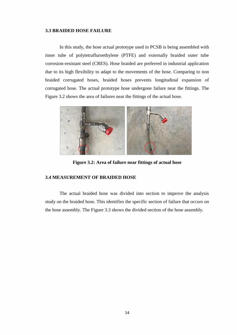
3.3 BRAIDED HOSE FAILURE
In this study, the hose actual prototype used in PCSB is being assembled with
inner tube of polytetrafluroethylene (PTFE) and externally braided outer tube
corrosion-resistant steel (CRES). Hose braided are preferred in industrial application
due to its high flexibility to adapt to the movements of the hose. Comparing to non
braided corrugated hoses, braided hoses prevents longitudinal expansion of
corrugated hose. The actual prototype hose undergone failure near the fittings. The
Figure 3.2 shows the area of failures near the fittings of the actual hose.
Figure 3.2: Area of failure near fittings of actual hose
3.4 MEASUREMENT OF BRAIDED HOSE
The actual braided hose was divided into section to improve the analysis
study on the braided hose. This identifies the specific section of failure that occurs on
the hose assembly. The Figure 3.3 shows the divided section of the hose assembly.

15
Figure 3.3: Braided hose assembly sections
The failure part of the hose occurs on hose section 3 and 6 (Figure 3.4 and
Figure 3.5). However, hose section 3 has minimal damage and the hose is not
elongated from its original diameter. In addition, hose section 6 were undergone
elongation and burned. The pipe is divided into points (left end of pipe as 0 cm)
according to the various diameters as shown in Table 3.1.
Figure 3.4: Hose Section 3
Figure 3.5: Hose Section 6
1
7
3
6
4
5
2

16
Table 3.4: Length and diameter of hose section 6
Length (cm) Diameter (mm)
2 11.26
4 11.14
6 11.40
8 11.46
10 11.45
12 11.50
14 11.57
16 11.65
18 11.50
20 11.45
22 11.44
The hose are cut into cross section to identify the fitting details of the hose as
shown in Figure 3.6. The end of the pipe are clamped between two layer fittings
15.27 mm away from visible hose. The length of the pipe is 220 mm for both
stainless steel and PTFE excluding the fitting. Both the hose outer and inner diameter
are measured using vernier caliper in the lab.
Figure 3.6: Cross section of hose fitting
3.5 MATERIAL IDENTIFICATION
The actual braided hose was received without any specifications or
dimensions. The material was identified by observation and military coding on the
body of the hose. The coding details are shown in Table 3.2.

17
Table 3.5: Military coding of braided hose
Item Description
Military Code MIL-DTL-25579
Title Hose Assembly, Polytetrafluoroethylene, High
temperature, Medium Pressure
Federal Supply Class (FSC): 4720 (Hose and Tubing, Flexible)
Hence, the black rubber material observed inside the actual braided pipe are
identified as polytetrafluroethylene (PTFE) or commonly known as Teflon®. Thus,
this identification of inner layer helped in the simulation study by inserting the
specific material properties of polytetrafluroethylene (PTFE).
3.6 MODELING USING SOLIDWORKS
The modeling was done for hose section 3 and 6. Both hose 3 and 6 are
assumed same length and diameter for fitting and braided pipe section for the
original measurement before failure. The diameters were taken using vernier caliper
obtained at the lab. The end of the pipe is extruded using SOLIDWORKS to replicate
the clamping of the fitting on the hose.
The actual braided hose are modelled in various in bend shapes. Figure 3.7,
Figure 3.8, Figure 3.9 and Figure 3.10 shows the actual hose modelled in various
bend shapes which are named horizontal hose, U shape hose, L shape hose and S
shape hose respectively.
Figure 3.7: Horizontal Hose

18
Figure 3.8: U Shape hose
Figure 3.9: L Shape hose
Figure 3.10: S Shape hose

19
3.7 ANSYS STATIC STRUCTURAL
Static Structural is an analysis that calculates the effects of steady loading
conditions on a structure, while ignoring inertia and damping effects, such as those
caused by time-varying loads. A static analysis include steady inertia loads (such as
gravity and rotational velocity), and time-varying loads that can be approximated as
static equivalent loads. Static analysis is used to determine the displacements,
stresses, strains, and forces in structures or components caused by loads that do not
induce significant inertia and damping effects. Steady loading and response
conditions are assumed; that is, the loads and the structure's response are assumed to
vary slowly with respect to time. In this project, the simulations are done by inserting
the specific material properties according to the material identification. Load is
applied as pressure inside the modelled hose and the ends of the pipe are fixed
support replicating the clamped hose between the fittings. The static equivalent loads
are applied and the solutions are based on stress distribution and deformation of the
simulation.
3.7.1 Physical Properties of Solid Geometry
Physical properties of solid geometry are important in order for simulation to
be done. These properties will show the characteristics of the material to withstand
the loads applied during the simulation. The physical properties of the material are
inserted in the simulation under Engineering Data on ANSYS static structural as
shown in Table 3.3.
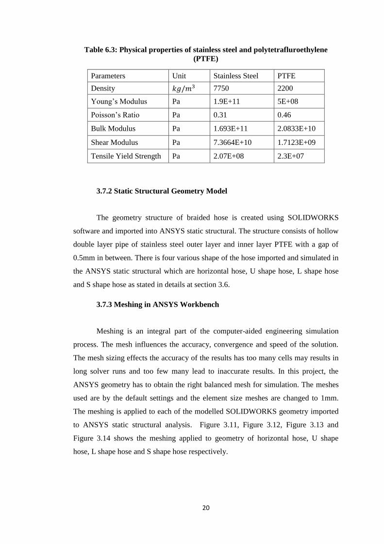
20
Table 6.3: Physical properties of stainless steel and polytetrafluroethylene
(PTFE)
Parameters Unit Stainless Steel PTFE
Density 𝑘𝑔/𝑚3 7750 2200
Young’s Modulus Pa 1.9E+11 5E+08
Poisson’s Ratio Pa 0.31 0.46
Bulk Modulus Pa 1.693E+11 2.0833E+10
Shear Modulus Pa 7.3664E+10 1.7123E+09
Tensile Yield Strength Pa 2.07E+08 2.3E+07
3.7.2 Static Structural Geometry Model
The geometry structure of braided hose is created using SOLIDWORKS
software and imported into ANSYS static structural. The structure consists of hollow
double layer pipe of stainless steel outer layer and inner layer PTFE with a gap of
0.5mm in between. There is four various shape of the hose imported and simulated in
the ANSYS static structural which are horizontal hose, U shape hose, L shape hose
and S shape hose as stated in details at section 3.6.
3.7.3 Meshing in ANSYS Workbench
Meshing is an integral part of the computer-aided engineering simulation
process. The mesh influences the accuracy, convergence and speed of the solution.
The mesh sizing effects the accuracy of the results has too many cells may results in
long solver runs and too few many lead to inaccurate results. In this project, the
ANSYS geometry has to obtain the right balanced mesh for simulation. The meshes
used are by the default settings and the element size meshes are changed to 1mm.
The meshing is applied to each of the modelled SOLIDWORKS geometry imported
to ANSYS static structural analysis. Figure 3.11, Figure 3.12, Figure 3.13 and
Figure 3.14 shows the meshing applied to geometry of horizontal hose, U shape
hose, L shape hose and S shape hose respectively.

21
Figure 3.11: Meshing of horizontal hose
Figure 3.11: Meshing of U shape

22
Figure 3.13: Meshing of L shape hose
Figure 3.12: Meshing of S shape hose
3.7.4 Static Structure Setup
After the meshing, the analyses settings are set on which load to apply to
certain faces of the geometry. For this project, 1500 psi or equivalent to 10.342 MPa
load are applied inside the layer of the polytetrafluroethylene (PTFE). This is due to
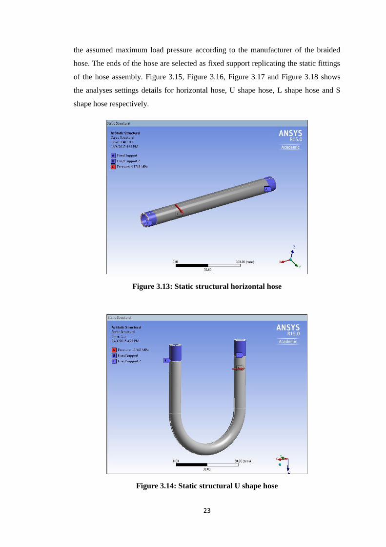
23
the assumed maximum load pressure according to the manufacturer of the braided
hose. The ends of the hose are selected as fixed support replicating the static fittings
of the hose assembly. Figure 3.15, Figure 3.16, Figure 3.17 and Figure 3.18 shows
the analyses settings details for horizontal hose, U shape hose, L shape hose and S
shape hose respectively.
Figure 3.13: Static structural horizontal hose
Figure 3.14: Static structural U shape hose

24
Figure 3.15: Static structural L shape hose
Figure 3.16: Static structural S shape hose

25
CHAPTER 4
RESULTS AND DISCUSSION
4.1 INTRODUCTION
The result is based on the ANSYS static structural simulation done on the
actual model of braided hose. The braided hose failures on hose section 3 and 6 are
predicted through stress distribution of Von Mises equivalent stress and total
deformation.
Von Mises stress is widely used to check whether the geometry will
withstand a given load condition. The concept of Von Mises stress arises from
the distortion energy failure theory which is distortion by volume and angular shape
of the design. The hose will fail, if the maximum value of Von Mises stress induced
in the material is more than strength of the material. The yield strength for stainless
steel and polytetrafluroethylene (PTFE) is 207 MPa and 23 MPa respectively.
Total deformation occurs due to the braided hose expansion and elongation
when the pressure is exerted to it. This deformation is due to the properties of
material which involves elastic and plastic deformation. The structure is forced to
expand and compress due to the pressure exerted, then the maximum deformation are
observed.
4.2 BRAIDED HOSE AT HORIZONTAL INSTALLATION
The first simulation is done where the braided hose is installed in horizontal
position (0 degree angle) with pressure of 10.342 MPa applied on the inside of the
tube (inner layer PTFE). The end results of the simulation are captured on the Von
Mises stresses and total deformation of the braided hose.
4.2.1 Von Mises Stress
Von Mises stress determines whether the design is safe for horizontal position
(0 degree angle). This shows that Von Mises stress is required before the

26
deformation of the design occur. The Von Mises stress simulation results of braided
hose with different focus on the material of the braided hose are shown in Figure 4.1
and Figure 4.2. The horizontal hose simulation results for Von Mises stress without
stainless steel body and PTFE body only are shown in Appendix A.
Figure 4.1: Von Mises stress on horizontal hose with full body
Figure 4.2: Von Mises stress on horizontal hose with PTFE

27
From the results, the maximum Von Mises stress is 108.12 MPa and the
minimum is 0 MPa. According to the yield strength of the stainless steel, the design
is safe. The Von Mises stress for the horizontal hose is less than the yield strength of
stainless steel which is 207 MPa. By installation of horizontal position, there was no
stress failure detected. The maximum stresses are mostly detected near the fittings of
the hose.
4.2.2 Total Deformation
Total deformation shows the maximum point where both the material
can withstand the deformation of plastic and elastic. As mentioned, the load pressure
10.342 MPa is exerted inside the PTFE layer. Figure 4.3 and Figure 4.4 illustrates the
results of the total deformation for horizontal hose with different focus on the body
of the braided hose. The horizontal hose simulation results for total deformation
without stainless steel body and PTFE body only are shown in Appendix A.
Figure 4.3: Total deformation on horizontal hose with full body

28
Figure 4.4: Total deformation on horizontal hose with PTFE
The results show that the maximum total deformation is 0.5572 mm for
horizontal hose position. According to the observation of the results for the layer of
stainless steel and PTFE, the total deformation is maximum near the fittings of the
hose. Due to the pressure exerted inside the PTFE layer and fixed support at the end
of the hose, the deformation is concentrated near the fittings. However, the PTFE
layer did not deformed beyond the stainless steel layer as predicted.
4.3 BRAIDED HOSE AT U SHAPE INSTALLATION
The second simulation is done where the braided hose is installed in U shape
position by bending the pipe. The pressure exerted is 10.342MPa. This simulation
run on the hose section modeled with both end fixed and pressure is applied on the
inside of the tube (inner layer PTFE). The end results of the simulation are captured
on the Von-Mises stresses and total deformation of the braided hose.

29
4.3.1 Von Mises Stress
Von Mises stress determines whether the design is safe for U shape position
of installation. This shows that Von Mises stress is required before the deformation
of the design occur. The Von Mises stress simulation results of braided hose with
different focus on the body of the braided hose are shown in Figure 4.5 and Figure
4.6. The U shape hose simulation results for Von Mises stress without stainless steel
body and PTFE body only are shown in Appendix A.
Figure 4.5: Von Mises stress on U shape hose with full body

30
Figure 4.6: Von Mises stress on U shape hose with PTFE
From the results, the maximum Von Mises stress is 137.32 MPa and the
minimum is 0 MPa. According to the yield strength of the stainless steel, the design
is safe. The Von Mises stress for the horizontal hose is again less than the yield
strength of stainless steel which is 207 MPa. By installation of horizontal position,
there was no stress failure detected. The maximum stresses are mostly detected at the
bending. However, the maximum stress is detected near the fittings for U shape hose
with the full body. This shows that when the hose position is full body, the stress is
concentrated near the fittings compared to the bending area of the hose.
4.3.2 Total Deformation
Total deformation shows the maximum point where both the material can
stand the deformation of plastic and elastic. As mentioned, the load pressure 10.342
MPa is exerted inside the PTFE layer. Figure 4.7 and Figure 4.8 illustrates the results
of the total deformation for U shape hose with different focus on the body of the
braided hose. The U shape hose simulation results for total deformation without
stainless steel body and PTFE body only are shown in Appendix A.

31
Figure 4.7: Total deformation on U shape hose with full body
Figure 4.8: Total deformation on U shape hose with PTFE

32
The results show that the maximum total deformation is 0.30033 mm for U
shape hose position which is less than the maximum for horizontal hose position.
This indicates, horizontal position have a higher chance of deforming. According to
the observation of the results for the layer of stainless steel and PTFE, the total
deformation is maximum again near the fittings of the hose. Due to the pressure
exerted inside the PTFE layer and fixed support at the end of the hose, the
deformation is concentrated near the fittings. However, the PTFE layer did not
deformed beyond the stainless steel layer as predicted.
4.4 BRAIDED HOSE AT L SHAPE INSTALLATION
The next simulation is done where the braided hose is installed in L shape
position by bending the pipe. The pressure exerted is 10.342 MPa applied on the
inside of the tube (inner layer PTFE). The end results of the simulation are captured
on the Von-Mises stresses and total deformation of the braided hose.
4.4.1 Von Mises Stress
Von Mises stress determines whether the design is safe for L shape position
of installation. This shows that Von Mises stress is required before the deformation
of the design occur. The Von Mises stress simulation results of braided hose with
different focus on the body of the braided hose are shown in Figure 4.9 and Figure
4.10. The L shape hose simulation results for Von Mises stress without stainless steel
body and PTFE body only are shown in Appendix A.

33
Figure 4.9: Von Mises stress on L shape hose with full body
Figure 4.10: Von Mises stress on L shape hose with PTFE

34
From the results, the maximum Von Mises stress is 88.432 MPa and the
minimum is 0 MPa. According to the yield strength of the stainless steel, the design
is safe. The Von Mises stress for the horizontal hose is again less than the yield
strength of stainless steel which is 207 MPa. L shape position indicates that it would
produce smaller Von Mises Stress compared to horizontal hose and U shape hose
installation. By installation of L shape position, there was no stress failure detected.
The maximum stresses are mostly detected near the fittings with and without the
stainless steel material.
4.4.2 Total Deformation
Total deformation shows the maximum point where both the material can
stand the deformation of plastic and elastic. As mentioned, the load pressure 10.342
MPa is exerted inside the PTFE layer. Figure 4.11 and Figure 4.12 illustrates the
results of the total deformation for L shape hose with different focus on the body of
the braided hose. The L shape hose simulation results for total deformation without
stainless steel body and PTFE body only are shown in Appendix A.
Figure 4.11: Total deformation on L shape hose with full body

35
Figure 4.12: Total deformation on L shape hose with PTFE
The results show that the maximum total deformation is 0.29126 mm for L
shape hose position which is less than the maximum for U shape position. This
indicates, horizontal position have a highest total deformation. According to the
observation, the layer of stainless steel and PTFE, the total deformation is maximum
near the bending area of the hose. This proves that when the hose undergoes a slight
deform in shape, the deformation concentrates at the area. However, the PTFE layer
did not deformed beyond the stainless steel layer as predicted.
4.5 BRAIDED HOSE AT S SHAPE INSTALLATION
The next simulation is done where the braided hose is installed in S shape
position by bending the pipe. The pressure exerted is 10.342MPa applied on the
inside of the tube (inner layer PTFE). The end results of the simulation are captured
on the Von-Mises stresses and total deformation of the braided hose.

36
4.5.1 Von Mises Stress
Von Mises stress determines whether the design is safe for L shape position
of installation. This shows that Von Mises stress is required before the deformation
of the design occur. The Von Mises stress simulation results of braided hose with
different focus on the body of the braided hose are shown in Figure 4.13 and Figure
4.14. The S shape hose simulation results for Von Mises stress without stainless steel
body and PTFE body only are shown in Appendix A.
Figure 4.13: Von Mises stress on S Shape hose with full body

37
Figure 4.14: Von Mises stress on S shape hose with PTFE
From the results, the maximum Von Mises stress is 159.8 MPa and the
minimum is 0 MPa. According to the yield strength of the stainless steel, the design
is safe. The Von Mises stress for the horizontal hose is again less than the yield
strength of stainless steel which is 207 MPa. However, the Von Mises stress is close
to the yield strength of the stainless steel. S shape position indicates that it would
produce much larger Von Mises Stress compared to the other hose installation. By
installation of S shape position, there was no stress failure detected but near to
failure. The maximum stresses are mostly detected near the fittings of the hose. The
full body of the S shape hose indicates maximum Von Mises diverted the Von Mises
stress away from the fittings.
4.5.2 Total Deformation
Total deformation shows the maximum point where both the material can
stand the deformation of plastic and elastic. As mentioned, the load pressure 10.342
MPa is exerted inside the PTFE layer. Figure 4.15 and Figure 4.16 illustrates the
results of the total deformation for S shape hose with different focus on the body of

38
the braided hose. The S shape hose simulation results for total deformation without
stainless steel body and PTFE body only are shown in Appendix A.
Figure 4.15: Total deformation on S shape hose with full body
Figure 4.16: Total deformation on S shape hose with PTFE

39
The results show that the maximum total deformation is 0.28982 mm for S
shape hose position which is smallest deformation compared to other installation
position. This further proves, horizontal position have a highest total deformation.
According to the observation of the results for the layer of stainless steel and PTFE,
the total deformation is maximum near the fittings. Due to the pressure exerted inside
the PTFE layer and fixed support at the end of the hose, the deformation is
concentrated near the fittings. However, the PTFE layer did not deformed beyond the
stainless steel layer as predicted.
4.6 DISCUSSION ON ANSYS SIMULATION ANALYSIS
From the results, the highest maximum Von Mises stress is 159.8MPa for S
shape hose. The lowest maximum Von Mises stress is L shape hose. For the S shape
hose, it is observed that the maximum stress location is between the bending of the
hose. As for the horizontal hose, U shape and L shape, the Von Mises stresses occur
near the fittings. From our actual braided hose failure, both hose section 3 and 6
undergo failure near the fittings. It is predicted that hose section 3 failure (located
7cm from nearest fittings) that the body is deformed to S shape, in order to get
similar stress location on hose.
The total deformation results show that the horizontal position has the highest
maximum deformation of 0.5572mm. The values followed by the U shape, L shape
and S shape with value 0.3033mm, 0.29126mm and 0.28982mm respectively. This
concludes that the total deformation does not depend on the shape has the values are
close. This proves that most of the deformation occurs near the fittings of the hose
except for the L shape hose which the deformation occurs at the bending area.
However, both Von Mises stress and total deformation have confirmed that the
maximum values of stress and deformation occurs near fittings. This concludes that
the failure of the actual braided has exceeded or reached 1500 psi overpressure
causing failure near point of fittings.

40
4.7 DISCUSSION ON FAILURE ANALYSIS
An analysis of potential failures helps designers focus on and understand the
impact of potential process or product risks and failures. Several systematic
methodologies have been developing to quantify the effects and impacts of failures.
Failure analysis was done on the braided hose failure to further predict the causes of
the situation. The failure analysis was focused on two common failure analysis
techniques which are Failure Modes Effects Analysis (FMEA) and Fault Tree
Analysis (FTA). Both failure analyses done are based on research papers obtained.
4.6.1 Failure Modes Effects Analysis (FMEA)
Table 4.2 shows the potential failure modes, the causes of failures and the
effects of failure based on the different aspect of the braided hose according to the
failure modes effects analysis (FMEA) method.
Table 4.1: Failure Modes Effects Analysis (FMEA) on braided hose failure
Item / Function
Potential
Failure
Mode(s)
Potential
Cause(s) of
Failure
Potential
Effect(s)
of Failure
Recommended
Action(s)
Outer layer of
stainless steel
braided metal
Wear Rubbing of
inner and
outer layer
Thinning of
braided metal
Reduce
vibration
Distorted Braided wire
metal
expansion
Misalignment of
hose
Monitoring
tool for
pressure
Burst Overpressure Exceed
maximum
allowable limit
Monitoring
tool for
pressure
Inner layer of
PTFE
Hole Overpressure Exceed
maximum
allowable limit
Monitoring
tool for
pressure
Thinning Cyclic life
fatigue
Leakage of fluid Monitoring
tool for cyclic
load
Fittings Leak Weak
welding
points
Leakage of fluid Leakage test
Fluid flow in
hose
Contaminants Presence of
hydrocarbon
Thinning of
PTFE layer
Check quality
of fluid

41
4.6.2 Fault Tree Analysis (FTA)
The Fault Tree Analysis shows the detailed root cause of the failures based on
the actual failure of the braided hose which is leakage on the hose body as shown in
Figure 4.17.
Figure 4.17: Fault Tree Analyses (FTA) on Braided Hose Leak
Leak
Human Error Hole on hose
Thinning of
PTFE Weak
weld
points
Leakage
test
failure
Pressure
too high
Hydro-
carbon
presence
Cyclic
life
fatigue

42
CHAPTER 5
CONCLUSION AND RECOMMENDATION
5.1 CONCLUSION
Braided hose leaked in major equipment have cost in material and time
consumed for maintained work. As experienced of PCSB, it is crucial to investigate
on how to improve the braided hose reliability and mechanism to detect the lose leak.
According to research papers found, there was no study done on industrial braided
hose failure. Most studies focused on automobile hose and braided components
which use finite element analysis.
From the results, the highest maximum Von Mises stress is 159.8MPa for S
shape hose. The lowest maximum Von Mises stress is L shape hose which is 88.432
MPa. The total deformation results show that the horizontal position has the highest
maximum deformation of 0.5572mm and lowest total deformation is for S shape
hose with value 0.28982mm. The deformation has minimal effect on the braided
hose failure.
However, both Von Mises stress and total deformation have confirmed that
the maximum values of stress and deformation occurs near fittings. The best shape
for installation is horizontal hose position for minimum stress on braided hose. To
prevent the hose from multi-plane bending, the hoses should be installed with
adapters. A hydraulic hose subjective to machine or actuator movement should be
routed properly with bracket or installed on the wall as shown in Figure 2.2. This
can prevent failure of the actual braided near point of fittings.
The main objectives are achieved as follows:
The type and characteristics of common braided hose have been identified by
has a metallic corrugated hose commonly used in the plant industry. The
outer layer of the hose is stainless steel braided metal with an inner layer of
polytetrafluroethylene (PTFE) or Teflon®.

43
The actual PCSB braided hose are modelled using SOLIDWORKS and
simulation has been done to detect the stress distribution by fixing forced at
the end of the pipe.
The possible reason of failure are predicted due to the overpressure of the
hose assembly that causes maximum Von Mises stress and deformation to
occurs near the fittings of the actual braided hose.
5.2 RECOMMENDATION
5.2.1 Current Project
The importance of identifying the possible reasons of failure is crucial in
avoiding unnecessary failure that occurs. However, using software simulation is not
adequate to analyze the point of failures it lack the actual environment. Below are
recommendations for future work for the current project:
Obtaining the actual braided hose installation position in the major equipment
to insert into the ANSYS static structural modelling and simulation.
The full modelling of hose assembly with braided wire should be done on
ANSYS static structural to find the stress distribution on total deformation
and Von Mises stress.
The hose assembly should be simulation using fluid structural interaction
(FSI) which is a combination of ANSYS fluent and ANSYS static structural.
Lab test experiment should be done on hose by hydraulic pressure with shell
tellus-68 hydraulic oil fluid inside the tube to simulate the actual situation on
the plant site.

44
5.2.2 PETRONAS Carigali Sdn Bhd (PCSB)
In order to prevent future braided hose failure, the technology for detecting
early hose leakage is proposed. The proposed technology is the Eaton: LifeSense
intelligent hydraulic hose condition monitoring system.
The system detects failure related events within a hose and provides advance
notification the product is approaching the end of its useful life. The notification
provides sufficient time for the hose to be replaced as a normal preventive
maintenance function, thereby minimizing both unscheduled downtime and the need
for corrective maintenance procedures associated with traditional replacement
processes.
The system comes in both wired and wireless technology to accommodate
different applications with various cable length and features for the industrial field.
However, only wired cables for the system are available in Malaysia. The details of
the technology are attached in Appendix B.

45
REFERENCES
Baaser, H. (2007). "Global optimization of length and macro–micro transition of
fabric-reinforced elastomers with application to a brake hose." Computational
Materials Science 39(1): 113-116.
Cho, J. R., Jee, Y.B., Kim, W.J., Han, S.R., Lee, S.B.. (2013). "Homogenization of
braided fabric composite for reliable large deformation analysis of reinforced rubber
hose." Composites Part B: Engineering 53: 112-120.
Hachemi, H., Kebir, H., Roelandt, J. M., & Wintrebert, E. (2011). A study of the
braided corrugated hoses: Behavior and life estimation. Materials & Design, 32(4),
1957-1966. doi: 10.1016/j.matdes.2010.11.075
Lee, G.-C., Kim, H.-E., Park, J.-W., Jin, H.-L., Lee, Y.-S., & Kim, J.-H. (2011). An
experimental study and finite element analysis for finding leakage path in high
pressure hose assembly. International Journal of Precision Engineering and
Manufacturing, 12(3), 537-542. doi: 10.1007/s12541-011-0067-y
Liang, W., Zhang, L., Xu, Q., Yan, C.. (2013). "Gas pipeline leakage detection based
on acoustic technology." Engineering Failure Analysis 31: 1-7.
Márquez, A., Fazzini, P. G., & Otegui, J. L. (2009). Failure analysis of flexible metal
hose at compressor discharge. Engineering Failure Analysis, 16(6), 1912-1921. doi:
10.1016/j.engfailanal.2008.09.031
Okularczyk, W. (2007). "Experimental investigations of guide rings made of
UHMWPE and PTFE composite in water hydraulic systems." Archives of Civil and
Mechanical Engineering 7(4): 167-176.
Pierce, S. O., & Evans, J.L. (2012). Failure analysis of a metal bellows flexible hose
subjected. Engineering Failure Analysis, 22, 11-20.

46
Rostum, J. (2008). Statistical Modelling of Pipe Failures in Water Networks.
Department of Hydraulic and Environmental Engineering.
Royals, W. T., Chou, T. C., & Steinberg, T. A. (1997). Flammability and Sensitivity
of Materials in Oxygen Enriched Atmospheres. American Society of Mechanical
Engineering (ASME).
Spellman, F. R. (2008). Handbook of Water and Wastewater Treatment Plant
Operations (Vol. Second Edition). CRC Press.
Voirin, E. (2011). COUPP-60 Hydraulic Hose Failure Analysis. Mechanical
Department Engineering Note. Fermilab.
Zhang, C. & X. Xu (2013). "Finite element analysis of 3D braided composites based
on three unit-cells models." Composite Structures 98: 130-142.
47
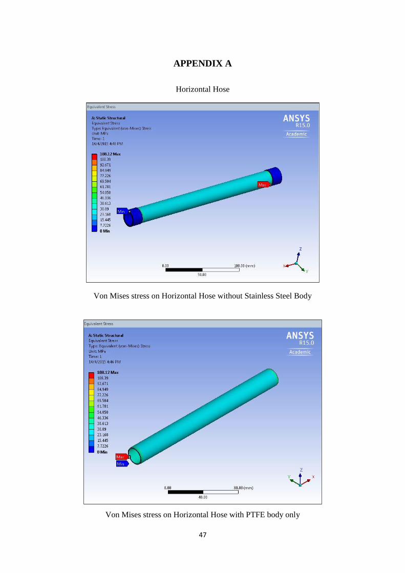
APPENDIX A
Horizontal Hose
Von Mises stress on Horizontal Hose without Stainless Steel Body
Von Mises stress on Horizontal Hose with PTFE body only

48
Total Deformation on Horizontal Hose without Stainless Steel Body
Total Deformation on Horizontal Hose with PTFE body only
49
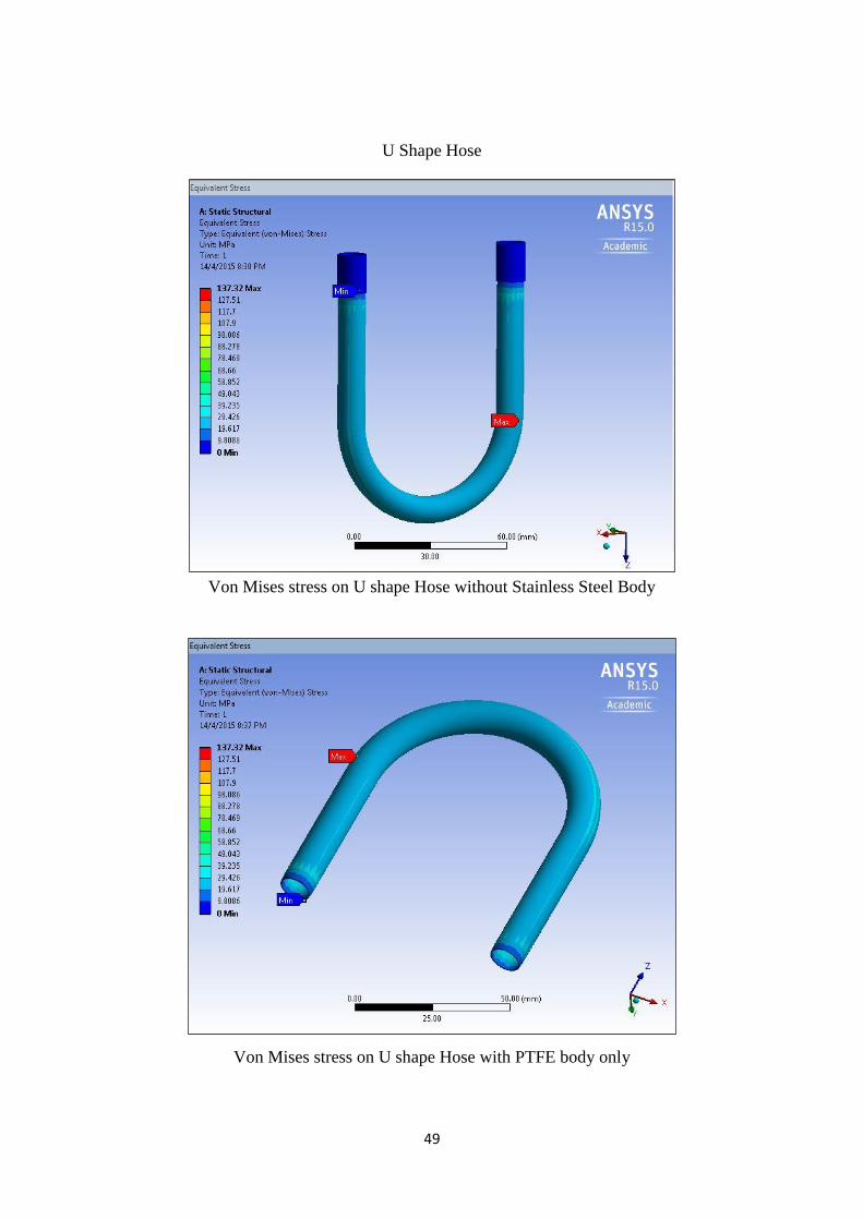
U Shape Hose
Von Mises stress on U shape Hose without Stainless Steel Body
Von Mises stress on U shape Hose with PTFE body only

50
Total Deformation on U shape Hose without Stainless Steel Body
Total Deformation on U shape Hose with PTFE body only

51
L Shape Hose
Von Mises stress on L shape Hose without Stainless Steel Body
Von Mises stress on L shape Hose with PTFE body only

52
Total Deformation on L shape Hose without Stainless Steel Body
Total Deformation on L shape Hose with PTFE body only

53
S Shape Hose
Von Mises stress on S shape Hose without Stainless Steel Body
Von Mises stress on S shape Hose with PTFE body only

54
Total Deformation on S shape Hose without Stainless Steel Body
Total Deformation on S shape Hose with PTFE body only

55
APPENDIX B

56

57

58

59

60