simultaneous 5-axis control processing...
TRANSCRIPT
Simultaneous 5-axis Control Processing Machine

Simultaneous 5-axis control revolutionizes the shop f loor
Mi-8
1
Medical equipment part Material : Titanium
Aircraft equipment part Material : Titanium
More than 70 years since the production of the first lathe. AMADA MACHINE TOOLS has won the trust of the customers by supplying excellent machine tools in the field of small precision part processing. This is testimony to their sincere and hard work in devising solutions to the problems the customers have to overcome. We continue to thoroughly examine what we can do as a leading machine tool builder in relation to the problems arising in the production field, where the demand to improve is getting increasingly more severe, and have developed a brand new turning center, the Mi-8, by reviewing the machine from the customers' standpoint. This simultaneous 5-axis control processing machine dedicated to the production of small complex parts is a creative integration of new technology, innovative design, and traditional expertise. Please take a look at the Mi-8, which integrates the lathe engineering technology of AMADA MACHINE TOOLS acquired through long years of tough work in this field.

2
Rigid Turret The 5-station turret and the independently operated tool spindle are mounted on the turret. The combination of a turret secured with a coupling and an 8000 min-1 high-speed turning spindle realizes high-speed and high-accuracy turning operation.
Improved Processed Face Accuracy Since tools can be tilted as required, the most appropriate processing position can be selected, which reduces chattering and shortens processing time. In addition, this feature allows processing of curved surfaces so that complex-shaped parts can be processed. The turning axis is used for processing and further accuracy improvement is possible by carrying out processing within the appropriate surface speed range.
ATC and High-speed Spindle The ATC can hold up to 20 rotary tools. Tool changes can be accomplished in a time as short as 5.5 sec. tool-to-tool without interference with adjacent tools. The high-speed tool spindle, featuring a maximum speed of 20000 min-1, can process small-diameter holes smaller than φ1 mm to high accuracy. Center through coolant is standard.
Simultaneous 5-axis Control Simultaneous 5-axis control is realized by adding a turning axis (A-axis) to the tool main spindle. This enables slanted hole processing, which is not achievable on a conventional turning center. In addition, the "complete in one chucking" feature eliminates dimensional error caused by re-chucking of a workpiece.
Compact Form through the Pursuit of Functional Beauty Designed based on ergonomics, with ease of operation in the machine in focus, the machine is built compactly with a low center of gravity. Installation requires a mere 4.62 m2 of floor area while high rigidity and sophisticated functions are realized. The low overall height of the machine, approximately 1.7 m, does not obstruct visibility in the workshop. A compact rotary stocker integrated with a robot can be installed to automate the production flow. X-axis
Z-axis
C-axis
Y-axis
A-axis
Tilt the tool
Short protrusion

3
As with the turning spindle, the tool spindle, which features minimized thermal displacement and high rigidity, operates at a maximum speed of 20000 min-1 to process holes as small asφ0.5 mm at a surface speed of 32 m/min. To hold rotary tools, an HSK shank suitable for high-speed operation is used. The two-face (end face and tapered face) constraint structure reduces positioning error in repeated operation to ensure high accuracy processing.
Tool Main Spindle
Axis Configuration
A built-in spindle, making the most of the experience we have acquired through manufacturing lathes, has been adopted to achieve high-accuracy processing. Four rows of bearings support the front part of the spindle to assure rigidity. In addition, a dedicated cooling unit is installed to minimize thermal displacement.
High-accuracy Built-in Spindle for Turning Operation
The introduction of the A-axis enables processing of slanted holes with the standard specification, without using the conventionally required angle unit. The "complete in one chucking" feature eliminates dimensional errors caused by re-chucking.
Axis
X-axis
Z-axis
Y-axis
C-axis
A-axis
Stroke
250mm
305mm
345mm
360deg
270deg
Minimum unit of setting
0.001mm
0.001mm
0.001mm
0.001deg
0.001deg
Turning spindle
NC unitFANUC 31i-A5
A-axis: 270 deg.A-axis: 270 deg.
Y-axis:345mm
Z-axis: 305 mm
X-axis: 250 mm
Y-axis:345mm
Z-axis: 305 mm
X-axis: 250 mm
C-axis: 360 deg.C-axis: 360 deg.
HSK shank
φ32
mm
Close contact with tapered face
Basic Machine Structure The ultimate machine, taking up the challenge of extreme accuracy without compromise
Close contact with end face
4
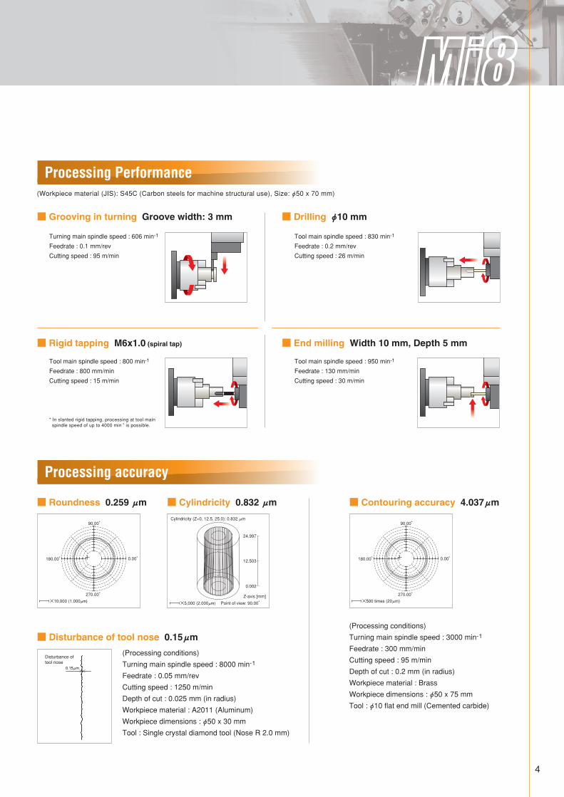
Processing Performance
Processing accuracy
■ Roundness 0.259 μm ■ Cylindricity 0.832 μm
■ Grooving in turning Groove width: 3 mm
(Workpiece material (JIS): S45C (Carbon steels for machine structural use), Size: φ50 x 70 mm)
■ Rigid tapping M6x1.0 (spiral tap) ■ End milling Width 10 mm, Depth 5 mm
■ Drilling φ10 mm
■ Disturbance of tool nose 0.15μm
90.00°
0.00° 180.00°
270.00°
×10,000 (1.000μm) ×5,000 (2.000μm)
0.15μm
Disturbance of tool nose
A-axis: 270 deg.
Y-axis:345mm
Z-axis: 305 mm
X-axis: 250 mm
C-axis: 360 deg.
(Processing conditions)
Turning main spindle speed : 8000 min-1
Feedrate : 0.05 mm/rev
Cutting speed : 1250 m/min
Depth of cut : 0.025 mm (in radius)
Workpiece material : A2011 (Aluminum)
Workpiece dimensions : φ50 x 30 mm
Tool : Single crystal diamond tool (Nose R 2.0 mm)
(Processing conditions)
Turning main spindle speed : 3000 min-1
Feedrate : 300 mm/min
Cutting speed : 95 m/min
Depth of cut : 0.2 mm (in radius)
Workpiece material : Brass
Workpiece dimensions : φ50 x 75 mm
Tool : φ10 flat end mill (Cemented carbide)
■ Contouring accuracy 4.037μm
Turning main spindle speed : 606 min-1
Feedrate : 0.1 mm/rev
Cutting speed : 95 m/min
Tool main spindle speed : 800 min-1
Feedrate : 800 mm/min
Cutting speed : 15 m/min
Tool main spindle speed : 830 min-1
Feedrate : 0.2 mm/rev
Cutting speed : 26 m/min
Tool main spindle speed : 950 min-1
Feedrate : 130 mm/min
Cutting speed : 30 m/min
* In slanted rigid tapping, processing at tool main spindle speed of up to 4000 min-1 is possible.
Cylindricity (Z=0, 12.5, 25.0): 0.832 μm
24.997
12.503
0.002
Point of view: 90.00°
Z-axis [mm]
90.00°
0.00° 180.00°
270.00°
×500 times (20μm)

5
■ CAD/CAM software supporting simultaneous 5-axis control processing
● The use of the CAM software reduces the time, skill and
verification needed in conventional programming.
● Complex shape can be programmed in a simple operation!
An operator who only has experience of operations on lathes can operate the software.
Even a complex shape can be programmed in a short time using the latest CAM software. The programmer’s load due to concentration for a long time, skills and verification steps, which were all necessary for conventional programming, can be reduced.
Software
FANUC 31i-MODEL A
NC Unit
■ OperabilityThe operation panel has been completely redesigned to improve operability by arranging the buttons in groups according to use.
Technology The Most Advanced Technology to Support Our Customers

6
■ Tool breakage detector
■ Robot FANUC Robot LR Mate 200iC
The 16-station stocker and the articulated robot, installed in an area 630 mm wide, serves as an automatic loading / unloading system. Multiple types of workpiece material can be handled since a CCD camera automatically recognizes the shape of the workpiece material.
Mi-8 [16-station stocker + Articulated robot specification]
The tool breakage detector provides the following two functions.
Detects breakage of a tool by receiving the light emitted from the photoelectric sensor.
Detects the length of a tool using the skip signal.
Detection of tool breakage
Automatic tool offset
Number of controlled axes
Reach
Wrist load capacity
Repeatability
Weight of robot body
6 axes
704 mm
Max. 5 kg*
±0.02 mm
Approx. 27 kg
* Includes the weight of hand, transport fixture and workpiece.

Standard accessories Special accessoriesCoolant unit Sub tank with spindle cooling unit Totally enclosing guard Machine light Hydraulic pump unit Foundation plate Air panel Safety guard Chuck air blow Tool main spindle coolant Lubricating oil level monitor Hydraulic pressure monitor Cycle time monitor CRT multi-counter 3-color signal tower OD turning tool holder Face turning tool holder Boring bar holder Chip pan 5″ hollow chuck (including cylinder)
Coolant pump of 250W (Tank capacity: 178L) 250W, Tank capacity: 120L
400W trochoid pump, with filter
Red / Yellow / Green □16 2 pcs. □16 2 pcs. φ25 2 pcs.
HO37M-5 (Howa)
(Hydraulic cylinder FR25 (Nikko))
Tool breakage detector Automatic tool diameter / tool length measuring unit Chip conveyor 4″ hollow chuck (including cylinder) Round bushing Mist collector Mist collector duct Energy saving related taxation system* compatible specification hydraulic pump unit*3
Automatic power OFF device Automatic fire extinguisher Chip cart Through-spindle air blow Through-spindle high-pressure coolant
Includes chip pan for chip conveyor HO37M-4 (Howa)
(Hydraulic cylinder FR25 (Nikko)) Various sizes of bushing
DM-3
Energy saving related taxation system* compatible inverter specification
*3 This hydraulic pump substitutes for the standard hydraulic pump unit
* Energy Demand Structure Reform Investment Promotion Taxation System
7
■ Accessories
■ Machine specifications
Standard workpiece size
Motor
Number of speed changes
Max. speed
Spindle nose
Number of ATC tools
Travel
Rapid traverse
Travel
Rapid traverse
Travel
Rapid traverse
Minimum setting unit
Rapid traverse
Minimum setting unit
Rapid traverse
Center height
Spindle nose
Bore
Number of speed changes
Max. speed
Motor
Positioning
NC unit
Type
Number of mountable tools
Turning tool size
Max. boring bar diameter
Turret swing
Machine height
Floor space
Machine weight
Power capacity
Voltage and frequency of power source
Unit
mm
kW
-
min-1
mm
pcs
mm
m/min
mm
m/min
mm
m/min
deg
min-1
deg
min-1
mm
-
mm
-
min-1
kW
-
-
-
pcs
mm
mm
mm
mm
mm×min
kg
kVA
-
Item Mi-8
□70 x 70 (swingφ100)
1.5/2.2 (Cont. / 5-min. rating)
Infinitely variable
20000
E32
20
250
20
345
23
305
20
0.001
28
0.001
300
900
φ80 Flat
φ32
Infinitely variable
8000*1
2.2/3.7 (Cont. / 30-min. rating)
NC Control (Cs-axis)
FANUC-31i-MODEL A5
V5
5*2
□16
φ25
φ390
1760 (Operation panel: 1850)
W1560XD2100 (3.28m2)
2700
21
200/220 VAC +10%, -15%, 3-phase 50/60 Hz ±1 Hz
Capacity
Numerically controlled axes
Tool spindle
X-axis
Y-axis
Z-axis
A-axis
C-axis
Turning spindle
Turret
*1 The maximum speed is limited by the type of chuck to be used. *2 The number of tools that can be mounted may be limited according to tooling.
Specifications

■ NC functions ○ Std. ▲ Opt.
■ NC unit
8
Backlash compensation
Stored pitch error compensation
Stored stroke check
Mirror image
Inch / metric switching
Single block
Manual pulse handle feed
Sequence number search
Dwell
Reference point return
Thread cutting / feed per revolution
Continuous thread cutting
Helical interpolation
Polar coordinate interpolation
Rapid traverse override
Feed override
Jog override
Plane selection (G17, G18, G19)
Canned cycles
Canned cycles for drilling
Custom macro B
Automatic coordinate system setting
Program number search
Program edit
Subprogram call
Coordinate system setting (G50)
Decimal point input / Calculator type input
Chamfering / Corner rounding
Work coordinate system G52 - G59
Block delete
Dynamic switching of diameter / radius specification
Direct input of drawing dimensions
Multiple repetitive cycles
Spindle orientation
Rigid tapping
Constant surface speed control
Tool position offset
Tool geometry / wear offset
Nose R compensation
Addition of tool offset pairs 64 / 69 sets
Number of registered programs 63
Program storage capacity 4 / 8MB
Number of registered programs 1000 / 4000
Background editing
Self-diagnostic function
Alarm history display
Operating time / Parts count display
Help function
External message function
Axis control
Operation
Interpolation function
Feed function
Program input
Miscellaneous function / Spindle function
Tool function / Tool offset function
Program edit operation
Setting display
Data input / output
Mi-8
○
○
○
○
▲
○
○
○
○
○
○
○
○
○
○
○
○
○
○
○
○
○
○
○
○
○
○
○
○
○
○
▲
▲
○
○
○
○
○
○
▲
○
▲
▲
▲
○
○
○
○
○
Control method and number of controllable axes
Least input unit (in diameter)
Command method
Input code
Number of tool offset pairs
Tool offset value
Feedrate command Feed per revolution
Spindle function
Preparatory function
Miscellaneous function
Tool function
Program storage capacity
*1 The range may be restricted according to rapid traverse rate and other factors.
Unit
-
mm (°)
-
-
sets
mm
mm/rev (°/rev)
-
-
-
-
Mbyte
Name FANUC 31i-MODEL A5
5 axes (simultaneous 5-axis control)
0.001 (X axis : Diameter / radius switchable)
Combined use of absolute and incremental
EIA / ISO automatic determination
32
0~±9999.999
0.001~500.000
S : 5 digits
G : 2 digits
M : 3 digits
T: 3 digits (tool) / D : 1 digit (offset)
2 (equivalent to approx. 5120 m)
Remarks
Unit in ( ) : C and A axes
Override : 0 to 150% Unit in ( ) : C axis*1

9
Stroke diagram
Tooling system drawing
4.4Nm
24Nm S2 30min.
2.6Nm
14Nm S1 Cont. 2.2kW S1 Cont.
3.7kW S2 30min.
Turning tools OD turning tool holder
Turning tool size□16
Round bushing
* Turning tools and boring bars should be prepared by the customer.
Turning tool□16
Boringφ25
Boring bar φ6φ8φ10φ12φ16φ20φ25
φ25×φ6φ25×φ8φ25×φ10φ25×φ12φ25×φ16φ25×φ20
Face turning tool holder
Turning tool size□16
Boring bar holder
Bore diameterφ25
250
5 (+X-axis stroke)
φ100
φ490
φ540
65 47
80 (3)
(20)
(20)
35
105
59
38
0
55
245 (-X-axis stroke)
X-axis home position
OD turning tool holder Face turning tool holder
End face of turning main spindle
97 63 145 90
105 105 (3)
4
16
10
1070
70
305
7
Headstock
φ135 (OD of 5″ chuck)
φ110 (OD of 4モ chuck)
φ390 Max. swing of turning tool
φ540 Arm swing
φ490 Tool turning
diameter
φ500 Max. swing of rotary tool
φ100
5 (+Z-axis stroke) 300 (-Z-axis stroke)
345
125
(130)
90
7550
134.5 134.5
(250)
340 (-Y-axis stroke)
5 (+Y-axis stroke)
180° (+A-axis stroke)
90° (-A-axis stroke)
ロ16
Z-axis home position
Y-axis home position
End face of rotary tool spindle
Boring bar holder
A-axis home position
155 90
160 Max. tool length (tool stored in the magazine)
Center of ATC arm rotation
Spindle cover
6.590
40°
Rotary tool
Rotary tool spindle end face
15
ATC arm stroke
ATC arm
(130) (90)
3.7kW S3 25%
1.5kW S1 Cont.
4,5003,000 4,760
7.0Nm S3 25%
3.2Nm S1 Cont.
4,7604,500
3,000
Round bushingTo be mounted to boring bar holder Various sizes of round bushing
OD turning tool holder
N1V001000A(□16)
Boring bar holder
N1V002000A(φ25)
Face turning tool holder
N1V003000A(□16)
Drawings

10
Floor requirement drawing
Spindle torque / Output characteristics
■ Tool spindle - Output characteristics (Automatic winding changeover)
■ Turning spindle - Output characteristics
4.4Nm
24Nm S2 30min.
1,5000 0
10
20
30
5,000 8,000 12,000
1.7
4.4Nm
2.6Nm 1.1
Torque(Nm)
Motor speed(min -1 )
14Nm S1 Cont.
24Nm S2 30min.
2.6Nm
14Nm S1 Cont.
0 0
1
2
3
4
5
5,0001,500
2.2kW S1 Cont.
3.7kW S2 30min.
2.2kW S1 Cont.
3.7kW S2 30min.
10,00012,000
1.5
2.2
Output(kW)
Motor speed(min -1 )
8,000
P A G E
P A G E
O K P R O G R A M M
O F F
C H U C K U N C L A M P
P R O T E C T
S T A R T O N
N C O N O F F
E R R O R
L I G H T A U T O
P O W E R O F F C Y C L E E N D
1 0 0 1 0 0
x 1 x 1 0
x 1 0 0
1 0 0
C Y C L E S T A R T
R E F E R E N C E
R E T U R N
M A N U A L
M O D E
M E M O R Y
E M E R G E N C Y S T O P
5 0 1 5 0
M D I
( % )
0
E D I T
1 2 0
6 0
( % )
5 0
T E M P O R A R Y S T O P
7 0
8 0
9 0 1 1 0
B L O C K D E L E T E
S I N G L E B L O C K
M 0 1
F E E D R A T E O V E R R I D E
S P I N D L E O V E R R I D E
E M E R G E N C Y R E S E T H A N D L E
Y Z C
X B
B
Y
C
Z
X
2 5
( % )
S E T
U P
5 0
R A P I D T R A V E R S E
0
F O R W A R D
A U T O O N
C O O L A N T M I S T
C O L L E C T O R O N A U T O
O N S T O P R E V E R S E
U N C L A M P C L O S E O P E N C L A M P
E N A B L E
I N C H I N G
T O O L D O O R
C H I P C O N V E Y O R
C A X I S M O D E
S A 2 S A 3 S A 1 S A 4
Coolant tank draw out space
R485
R715
R450
R315R5
25
R525
Mist collector duct (Option)
Chip conveyer (Option)
Spindle center
Automatic fire extinguisher (Option)
Mist collector (Option)
Maintenance space for the spindle, the control box and the hydraulic pump
1380
1850
1760
1096
900
840
1 5 60 445500
370
2065
637
1030
1030
37
208
1 3 5°
0 0
5
4
3
2
1
5,000 10,000 20,00015,000
Output(kW)
Motor speed(min -1 )
3.7kW S3 25%
1.5kW S1 Cont.
3.7kW S3 25%
2.2kW
1.5kW S1 Cont.
8,0004,5003,000 4,7604,500
3,000 4,760
4.4Nm
8,000
5,000 10,000 15,000 20,0000 0
8
6
4
2
10
1.8
0.7
Torque(Nm)
Motor speed(min -1 )
7.0Nm S3 25% 7.0Nm S3 25%
3.2Nm S1 Cont. 3.2Nm S1 Cont.
4,7604,7604,5004,500
3,0003,000
The tool main spindle motor type is the output changeover type. When the motor speed exceeds 4760 min-1, the motor characteristics change from those of a low-speed winding to those of a high-speed winding.
0LK-10099-A002 2009.09
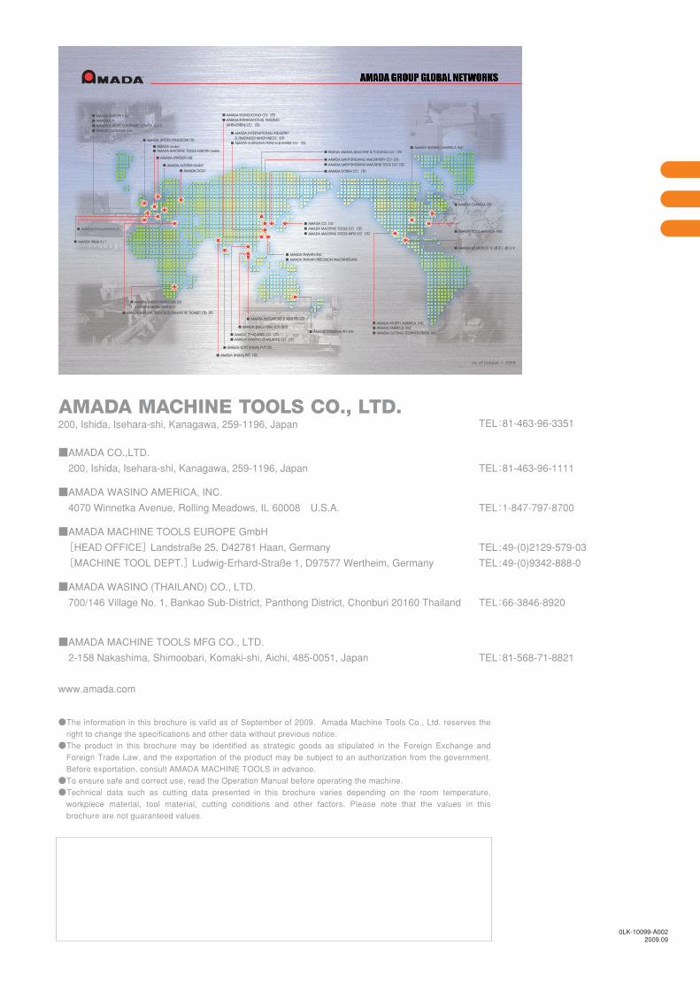
●The information in this brochure is valid as of September of 2009. Amada Machine Tools Co., Ltd. reserves the right to change the specifications and other data without previous notice. ●The product in this brochure may be identified as strategic goods as stipulated in the Foreign Exchange and Foreign Trade Law, and the exportation of the product may be subject to an authorization from the government. Before exportation, consult AMADA MACHINE TOOLS in advance.
●To ensure safe and correct use, read the Operation Manual before operating the machine. ●Technical data such as cutting data presented in this brochure varies depending on the room temperature, workpiece material, tool material, cutting conditions and other factors. Please note that the values in this brochure are not guaranteed values.
TEL:81-463-96-1111
TEL:1-847-797-8700
TEL:49-(0)2129-579-03
TEL:49-(0)9342-888-0
TEL:66-3846-8920
TEL:81-568-71-8821
■AMADA CO.,LTD.
200, Ishida, Isehara-shi, Kanagawa, 259-1196, Japan
■AMADA WASINO AMERICA, INC.
4070 Winnetka Avenue, Rolling Meadows, IL 60008 U.S.A.
■AMADA MACHINE TOOLS EUROPE GmbH
[HEAD OFFICE] Landstraße 25, D42781 Haan, Germany
[MACHINE TOOL DEPT.] Ludwig-Erhard-Straße 1, D97577 Wertheim, Germany
■AMADA WASINO (THAILAND) CO., LTD.
700/146 Village No. 1, Bankao Sub-District, Panthong District, Chonburi 20160 Thailand
■AMADA MACHINE TOOLS MFG CO., LTD.
2-158 Nakashima, Shimoobari, Komaki-shi, Aichi, 485-0051, Japan
www.amada.com
TEL:81-463-96-3351200, Ishida, Isehara-shi, Kanagawa, 259-1196, Japan