sinamics g115d – distributed drive system - technical slides
TRANSCRIPT

Unrestricted © Siemens 2021
siemens.com/sinamics-g115dUnrestricted © Siemens 2021
SINAMICS G115D Distributed drive system

Unrestricted © Siemens 2021
Conveyor technology and sortation systems applications
Page 2
SINAMICS G115D addresses conveyor apps. for Intra-
logistics, Airports and partly Automotive and F&B markets
• Roller, Belt and Chain Conveyors
(with fixed or variable speed)
• Corner turntable
• Turntable
• Travelling Trolley
• …
• Baggage handling systems
• Tray-based conveyor lines /
systems for baggage
• Cargo handling systems
• Sortation systems
• …
• Belt conveyors
• Roller conveyors
• Apron conveyors
• …
• Roll conveyor
• Turntable
• Travelling Trolley
• …
Turntable/
corner turntable
Corner
turntable Lift
Airports Automotive F&BIntralogistics
Travelling
trolley
Conveyor
All covered by the new SINAMICS G115D distributed drive system!

Unrestricted © Siemens 2021
Page 3
The new SINAMICS G115D distributed drive system
is not only a drive… It’s the solution…
• Out-of-the-box concept for easy handling, fast set up
time and extremely simple to operate design for
applications in the mid range segment
• User friendly, modular solution with a new construction
design for easy wiring, commissioning and servicing
incl. dedicated features for conveyors
• The SINAMICS G115D distributed drive system comprises
drive, motor and gear in both Motor and Wall Mounted
versions 0.37 to 4 kW (MM) and 0.37 to 7.5 kW (WM)Wall
Mounted
Motor
Mounted
WM: Wall Mounted
MM: Motor Mounted

Unrestricted © Siemens 2021
SINAMICS G115D distributed drive system –
Position within Siemens portfolio
Page 4
Basic Midrange High-End
SINAMICS G120D
SIMATIC ET200pro FC-2
Distributed
drives systems
for
moving
application
with
continuous
motion
SINAMICS G115D
Decentralize drive system
SINAMICS G110D
SINAMICS G110M
NEW
SINAMICS V20
NEW

Unrestricted © Siemens 2021
All parameters of the SINAMICS G115D system can be
pushed natively to MindSphere via PROFINETIn
-Mach
ine
(Fie
ld l
eve
l)
HTTPS to Mindsphere
native MindSphere data model
S7 parameter services/ PROFINET
V90
SIN
AM
ICS
dri
ves
G115D MM
MindConnect IoT 2040 IPC 227E nanoSIMATIC S7-1500/ 1200
Standard MindConnect Portfolio
G115D WMG120 G120C G120X G120D S210 G130 S120 S150
Page 5

Unrestricted © Siemens 2021
SINAMICS G115D distributed drive system –
Top highlights
Feature / Function Benefits
Out-of-the-box approach / easy to
order and use
• Reduced cost and efforts for:
ordering (1 article number), factory
pre-commissioned
New modular construction concept:
electronic module + wiring module
• Easy to install and exchange –
same electronic module for all drives
Full integration into TIA Portal
(Startdrive) and optimized Webserver
(SAM) via Smart-Access-Module
• Faster and easier commissioning
process with improved user friendly
wizards
Optimized design: 3C2 coating +
extended operating temperatures -30
to 40 …55˚C (with derating)
• Ability to work in harsh
environments (incl. deep freeze
applications)
Safety STO SIL 2 / PROFIsafe • Standard compliant and easy
certification process
Compatible with MindConnect
portfolio
• Fit for digitalization and for cloud
based analytics
Plug-in connector system or gland
cable connection from three1 sides
• Flexible connecting variants for
installation, service and maintenance
Page 6
TIA
Wall
Mounted
Motor
Mounted
1 for Motor Mounted or from below for Wall Mounted

Unrestricted © Siemens 2021
SINAMICS G115D distributed drive system includes
2 system offerings – based on 1 seamless platform
Communication
Gear Box
Power range / size
Motor
System G115D - Motor Mounted G115D - Wall Mounted
0.37 kW
0.55 kW
0.75 kW
1.1 kW
1.5 kW
2.2 kW
4 kW
3 kW
2KJ8 2KJ8 (2KJ3 or 3rd p.)
6SL35 Cable
7.5 kW
5.5 kW
IO controlAS-iPROFINET / EtherNet/IP
Asynchronous 1LE1 Synchronous Reluctance 1FP
Bevel Helical Worm
FSB FSA
0.37 kW
0.55 kW
0.75 kW
1.1 kW
1.5 kW
2.2 kW
4 kW
3 kW
FSB FSA FSC
Structure
Page 7
Helical Parallel Shaft Monorail

Unrestricted © Siemens 2021
SINAMICS G115D distributed system –
Dimensions
Page 8
G115D - Wall Mounted
FSPower range (kW)
380-480V
Width
(W)Height (H) Depth (D) Connector (C)1
FSA 0.37 – 1.5 380 (15) 156 (6.1) 129 (5.1)
Connector variant
+47.5 (1.87)FSB2 2.2 – 4 425 (16.7) 180 (7.1) 169 (6.7)
FSC 5.5 – 7.5 425 (16.7) 180 (7.1) 169 (6.7)
G115D - Motor Mounted
FS
Power range
(kW)
380-480V
Motor
FS
Length
(L)Length (l1)
Width
(W)
Height
(SH)
Connector
(C)1
FSA 0.37 – 1.5
71240
(9.4)
53.5 (2.11)146
(5.7)
177.5 (7)
Connector
variant
+47.5
(1.87)
80 25 (0.98) 196 (7.7)
90 0.5 (0.02) 201 (7.9)
FSB 2.2 – 4
90285
(11.2)
27 (1.06)180
(7.1)
206 (8.1)
100 5 (0.2) 217.5 (8.6)
112 -3 (-0.12) 228.5 (9)
Clearance distance: Maintain a minimum clearance distance of 150 mm (5.9 in) around and above the converter. Side-by-side installation possible.
All dimensions in mm (inch)
1 The dimension data of the cable glands is not provided here2As of now = >2.2 kW (FSB) with fan, later on from >=4 kW (in preparation)
All dimensions in mm (inch)

Unrestricted © Siemens 2021
SINAMICS G115D distributed drive system –
Mounting positions
Page 9
G115D - Wall Mounted
All mounting positions are permissible
G115D - Motor Mounted
All mounting positions are permissible

Unrestricted © Siemens 2021
Electronic module Wiring module
SINAMICS G115D distributed drive system –
Converter components
SINAMICS G115D = Electronic module + Wiring module
Page 10
Modular concept
• New Same electronic
module for both
versions
+
Motor Mounted Wall Mounted Motor Mounted Wall Mounted

Unrestricted © Siemens 2021
G115D Motor Mounted – Connections overview
Hardware description
1 = Line supply interface (IN)
2 = Line supply interface (OUT)
3 = 24 V DC power supply interface (IN)
4 = 24 V DC power supply interface (OUT)
5 = PROFINET interfaces
6 = Digital inputs DI 0 and DI 1
7 = Digital inputs DI 2 and DI 3
8 = Bidirectional digital inputs/outputs DIO24 and DIO25
10= External braking resistor interface
11= Fan unit connector
12= Status LED
13= Commissioning interface (mini USB interface
and two potentiometers)
15= Memory card interface
Motor Mounted – Connection’s overview
Line supply 24V DC power supply PROFINET DIs Bidirectional DIs/DOs
Page 11

Unrestricted © Siemens 2021
G115D Wall Mounted – Connections overview
Hardware description
1 = Line supply interface (IN)
2 = Line supply interface (OUT)
3 = 24 V DC power supply interface (IN)
4 = 24 V DC power supply interface (OUT)
5 = PROFINET interfaces
6 = Digital inputs DI 0 and DI 1
7 = Digital inputs DI 2 and DI 3
8 = Bidirectional digital inputs/outputs DIO
9 = Motor power interface motor
10= External braking resistor interface
11= Fan unit connector
12= Status LED
13= Commissioning interface (mini USB interface
and two potentiometers)
14= Repair switch
15= Memory card interface
Wall Mounted – Connection’s overview
Line supply 24V DC power supply PROFINET DIs
Bidirectional DIs/DOs
Motor power interface
Page 12

Unrestricted © Siemens 2021
Cost effective
• 400V and 24V: Gland
• Communication: M12 connectors
• I/Os: Gland, optional M12 connectors
• Motor (only Wall Mounted): At the converter gland, to
the motor connector
• Optional integrated 24V power supply
+
G115D motor and Wall Mounted – Wiring module
Installation via gland
Page 13
G115D - Wall MountedG115D - Motor Mounted
With optional integrated 24V DC1:
1Also valid for the G115D Motor Mounted version

Unrestricted © Siemens 2021
SINAMICS G115D distributed drive system
Integrated communication
Page 14
I/O control AS-i PROFINET / Ethernet IP
• Basic variant with I/O control instead
of fieldbus communication
• Control of the G115D via digital inputs
• Status feedback via digital outputs
• Integrated AS-i communication
• Single and dual slave functionality
integrated
• The DI and DO of the G115D can be
used as decentralized periphery of the
PLC
• Integrated PROFINET incl. PROFIsafe
and PROFIenergy
• Alternative EtherNet/IP COM
• The DI and DO of the G115D can be
used as decentralized periphery of the
PLC
Different integrated communication options to fit your application’s need!

Unrestricted © Siemens 2021
DI0
DI1
DI2
DI3
DI24
DI25
G115D
Page 15
SINAMICS G115D System –
Integrated I/Os can be combined in different use cases
4 DI and 2 DO 6 DI (DO as DI)
2 DI as F-DI 2 DI as HTL-Encoder interface
• DI status and DO control via
fieldbusAS-i or
PROFINET
• DI status via fieldbus
AS-i or
PROFINET
• DI status and DO ctrl via
fieldbus
• F-DI status via PROFIsafe
PROFINET
• DI status, DO control and
counter value via
PROFINET
PROFINET
G115D
DI0
DI1
DI2
DI3
DO24
DO25
G115D
DI0
DI1
DI2
DI3
DO24
DO25
G115D
DI0
DI1
DI2
DI3
DO24
DO25G
A
B
1 3
42

Unrestricted © Siemens 2021
Page 16
Safe Torque Off (STO) – Safety integrated functionality
Using fail-safe digital input corresponding to PL d and SIL 2
While rotating (B)
A converter with active STO function prevents energy supply to
the motor, so it can no longer generate torque at the motor shaft.
Principle of operation
1. Converter recognizes the selection of STO via F-DI or via
PROFIsafe communication
2. Interrupts the energy supply to the motor
3. Signals that “STO is active” via PROFIsafe
At standstill (A)
Speed
Select STO
STO is active
Safe Torque Off functionality Wiring example according to EN13849-1/IEC 61508
Unrestricted © Siemens 2021
Page 17
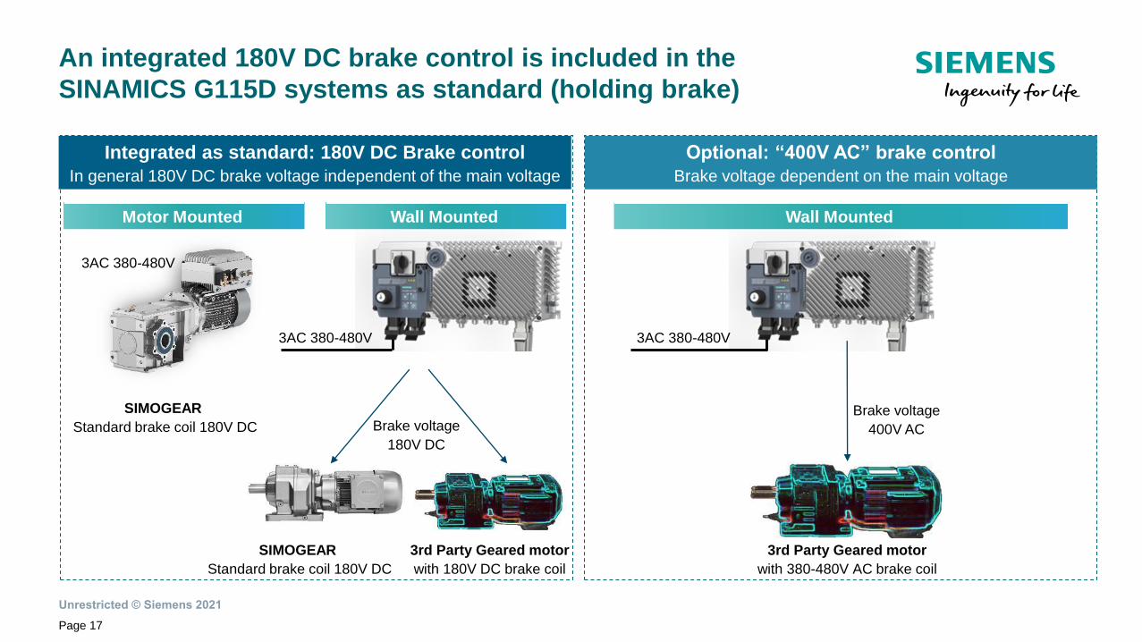
An integrated 180V DC brake control is included in the
SINAMICS G115D systems as standard (holding brake)
SIMOGEAR
Standard brake coil 180V DC
3rd Party Geared motor
with 180V DC brake coil
3rd Party Geared motor
with 380-480V AC brake coil
Integrated as standard: 180V DC Brake control
In general 180V DC brake voltage independent of the main voltage
Optional: “400V AC” brake control
Brake voltage dependent on the main voltage
Brake voltage
180V DC
Brake voltage
400V AC
3AC 380-480V 3AC 380-480V
Motor Mounted Wall Mounted Wall Mounted
SIMOGEAR
Standard brake coil 180V DC
3AC 380-480V

Unrestricted © Siemens 2021
SINAMICS G115D distributed drive system –
Diagnostic’s overview
Page 18
G115D – Motor Mounted
G115D – Wall Mounted
Fast and on-site
• Available diagnosis LEDs
showing general status,
communication and NEW
Status of the I/Os
+
Fieldbus diagnosis
• Extensive diagnostics
via AS-i and PROFINET
• Alarms & faults can be
read and acknowledge
+
G115D’s LEDs

Unrestricted © Siemens 2021
Page 19
SINAMICS G115D distributed drive system –
Options overview
G115D - Wall MountedG115D - Motor Mounted
New Optional integrated repair
switch with feedback signal
Options
– 1 Yes
Optional integrated local / remote
control
New Optional integrated 24V DC
power supply
New Optional AC 400V holding
brake control
Flexible options
• Many options via
“integrated” components
Compact design
• Less external components
+
– 1 Yes
Yes Yes
– Yes
New Optional Wi-Fi webserver
via Smart Access Module (SAM)Yes Yes
1 External - planned

Unrestricted © Siemens 2021
Optional: Smart Access Module
Webserver via Wi-Fi
SAM: Smart-Access-Module
Page 20
• To the drive even if installed in difficult-to-access areas
• No cable necessary due to wireless one-to-one connection to
mobile device or PC
Convenient access
SINAMICS Smart Access Module (SAM)
• No apps/downloads required
• Operates with any of the common browsers and with any end
device
Set up in less than one minute
• All functions are provided by the integrated web server
• One module support most of the G120 series
• 6 languages support/ Upgradable language packages
• IP55 protection level
All-in-one solution
• Due to intuitive/guided user interface
• Look & feel of an app
• Higher functionality than BOP
Simple operation
• Point to point connection/ No internet need
• WAP-2 encryption
• Support HTTPS/HTTP communication protocol
Information security
Mobile device view (Smartphones, tablets or PC)
Up to 50m
Wi-Fi

Unrestricted © Siemens 2021
Flexible setup options and fast commissioning thanks to full
integration into SAM webserver and TIA tool landscape
Commissioning via StartdriveCommissioning via SAMCommissioning via DIP switches
Basic commissioning without
communication
• Allows basic commissioning (motor
type, ∆/Y, brake, Temp. sensors) of the
system
• Preferable for G115D IO-Control
• Dedicated user interface including
conveyor applications via optimized
SAM (webserver)
• Full integration of the system
• Graphical parameterization of
conveyor applications
Quick and easy commissioning via full integration
within Startdrive and the Smart Access Module!
Page 21

Unrestricted © Siemens 2021
SINAMICS G115D distributed drive system –
Integrated functions for conveyor technology
Page 22
Corner turntable lift with fast- / slow
speed, Quick-Stop and limit switch
Turntable with fast- / slow speed, Quick-
Stop and limit switch (2 or 3 positions)
Travelling trolley with fast- / slow speed,
Quick-Stop and limit switch
Easy to use functions
• Standard integrated
conveyor functions (in PN
and AS-i Variants)
• New Wizard for Startdrive
and Smart Access Module
+
Benefits
• Reproducible stop reaction
• Reduced load of the PLC
+
Conveyor with fast- / slow speed and
Quick-Stop (1 or 2 directions)

Unrestricted © Siemens 2021
Page 23
Conveyor control:
One direction and one speed
Related parameters: p1070, p1113, p3384, p3390, p3394
1 direction and 1 speed (p3393 = 1)
Precondition: A sensor is required to signal the limit. The signal of the sensor needs to be
interconnected with the digital input of choice
Feature/ Function
With the ON command, the motor accelerates to its speed
setpoint (p1070). The direction of the movement depends on the
setpoint inversion:
• p1113 = 0: positive direction
• p1113 = 1: negative direction
The motor stops with OFF1 ramp when the stop sensor
positive direction (p3384) is triggered
(level/edge triggered depending on p3394).
Setting the sensor bypass signal (p3390) to 1 overrides the stop
sensor signal p3384.
The converter enables the load on a conveyor belt to
move in one direction with a fixed speed

Unrestricted © Siemens 2021
Page 24
Conveyor control:
One direction and two speeds
1 direction and 2 speeds (p3393 = 2)
Precondition: 2 sensors are required to signal the limit positions for the motor to stop or
decelerate. The signal of the sensors needs to be interconnected with the digital input of choice
Feature/ Function
With the ON command, the motor accelerates to the high
speed setpoint (p3397). The direction of the movement depends
on the setpoint inversion:
• p1113 = 0: positive direction
• p1113 = 1: negative direction
The motor decelerates with OFF1 ramp to the low speed
setpoint (p3398) when the low speed sensor positive direction
(p3387) is triggered (level/edge triggered depending on p3395).
The motor stops with OFF1 ramp when the stop sensor
positive direction (p3384) is triggered (level/edge triggered
depending on p3394).
Setting the sensor bypass signal (p3390) to 1 overrides the
sensor signals p3384 and p3387
The converter enables the load on a conveyor belt to
move in one direction with variable speeds
Related parameters: p1113, p3384 , p3387, p3390, p3394 … p3398
Unrestricted © Siemens 2021
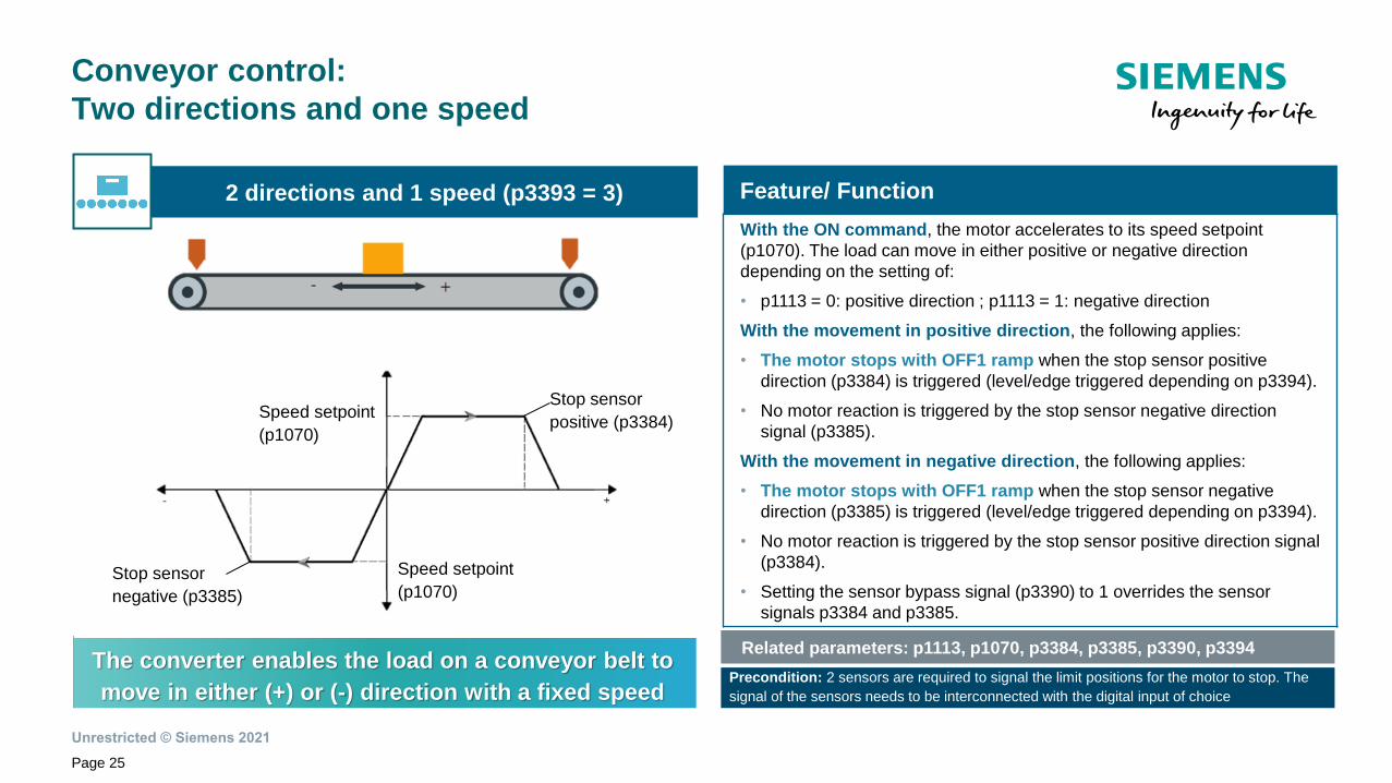
Related parameters: p1113, p1070, p3384, p3385, p3390, p3394
Page 25
Conveyor control:
Two directions and one speed
2 directions and 1 speed (p3393 = 3)
Precondition: 2 sensors are required to signal the limit positions for the motor to stop. The
signal of the sensors needs to be interconnected with the digital input of choice
Feature/ Function
With the ON command, the motor accelerates to its speed setpoint
(p1070). The load can move in either positive or negative direction
depending on the setting of:
• p1113 = 0: positive direction ; p1113 = 1: negative direction
With the movement in positive direction, the following applies:
• The motor stops with OFF1 ramp when the stop sensor positive
direction (p3384) is triggered (level/edge triggered depending on p3394).
• No motor reaction is triggered by the stop sensor negative direction
signal (p3385).
With the movement in negative direction, the following applies:
• The motor stops with OFF1 ramp when the stop sensor negative
direction (p3385) is triggered (level/edge triggered depending on p3394).
• No motor reaction is triggered by the stop sensor positive direction signal
(p3384).
• Setting the sensor bypass signal (p3390) to 1 overrides the sensor
signals p3384 and p3385.
The converter enables the load on a conveyor belt to
move in either (+) or (-) direction with a fixed speed
Stop sensor
positive (p3384)
Speed setpoint
(p1070)Stop sensor
negative (p3385)
Speed setpoint
(p1070)

Unrestricted © Siemens 2021
Page 26
Conveyor control:
Two directions and two speeds
2 directions and 2 speeds (p3393 = 4) Feature/ Function
With the ON command, the motor accelerates to the high
speed setpoint (p3397). The load can move in either (+) or (-)
direction, depending on:
• p1113 = 0: positive direction; p1113 = 1: negative direction
With the movement in positive direction:
• The motor decelerates with OFF1 ramp to the low speed
setpoint (p3398) when the low speed sensor positive direction
(p3387) is triggered (level/edge triggered depending on
p3395).
• The motor stops with OFF1 ramp when the stop sensor
positive direction (p3384) is triggered (level/edge triggered
depending on p3394).
• No motor reaction is triggered by the stop sensor negative
direction (p3385) and low speed sensor negative direction
(p3388) signals.The converter enables the load on a conveyor belt to
move in either (+) or (-) direction with variable speeds
Unrestricted © Siemens 2021
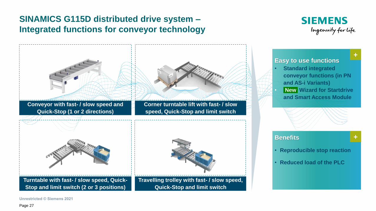
SINAMICS G115D distributed drive system –
Integrated functions for conveyor technology
Page 27
Corner turntable lift with fast- / slow
speed, Quick-Stop and limit switch
Turntable with fast- / slow speed, Quick-
Stop and limit switch (2 or 3 positions)
Travelling trolley with fast- / slow speed,
Quick-Stop and limit switch
Easy to use functions
• Standard integrated
conveyor functions (in PN
and AS-i Variants)
• New Wizard for Startdrive
and Smart Access Module
+
Benefits
• Reproducible stop reaction
• Reduced load of the PLC
+
Conveyor with fast- / slow speed and
Quick-Stop (1 or 2 directions)

Unrestricted © Siemens 2021
SINAMICS G115D distributed drive system –
Added value topics
Page 28
Dedicated to
conveyors
Robust &
reliable:
Cost efficient:
Seamless &
simple:
Fit for
digitalization:
• TIA /Startdrive = fully integrated into powerful automation tool
• Smart Access Module = webserver for setup & diagnostics
• Analyze My Drive = pulls & evaluates operation data in the cloud
• New flexible design = Electronic + Wiring module
• Safety integrated = Safe Torque Off via F-DI or PROFIsafe
• Temperature range = - 30 to 55°C (deep freeze applications)
• Flexible wiring = wide space, diff. side connections possibilities
• Energy efficient = asynchronous & reluctance motors usability
• Grid friendly: reduced blind currents & improved cos phi
• Out of the box = pre-commissioned system from factory
• Easy to use = user friendly setup and operation tools
• World motor = one winding for world main voltages
• One platform = for Motor Mounted & Wall Mounted versions
• I/O variable assignment = for sensor and actuators
• Fast commissioning = conveyor application wizards
+
+
+
+
+
• Out of the box = pre-commissioned system from factory
• Easy to use = user friendly setup and operation tools
• World motor = one winding for world main voltages
Wall
Mounted
Motor
Mounted
TIA
SINAMICS G115D

Unrestricted © Siemens 2021
SINAMICS G115D system includes higher motor efficiency
and increased performance on the motor side
Page 29
High Motor efficiency
• Future proof efficiency concept for
inverter duty according
IEC60034-30-2
• IE3 as standard
• IE4 with reluctance motor
• Environmentally friendly with no
magnets (rare earths) inside
+
Increased performance w. RESM
• Low inertia allows high dynamics,
sensorless vector control
• Precise speed even without encoder,
no need for encoder in many
applications
• High permanent overload possible in
high speed range
+
Motor availability
• Worldwide improved standard
delivery time: ~15 Working days
• Extra quick delivering possible on
request
+
Integrated brake concept
• New holding brake integrated as
standard - voltage supply (180V)
independent of power grid voltage
• Other optional brake voltage
supplies for the wall mount version
are planned
+
Certifications
• Worldwide, multi certifications for
EU / US / CN / Korea / Russia / India
+
RESM: Reluctance synchronous motors
Unrestricted © Siemens 2021
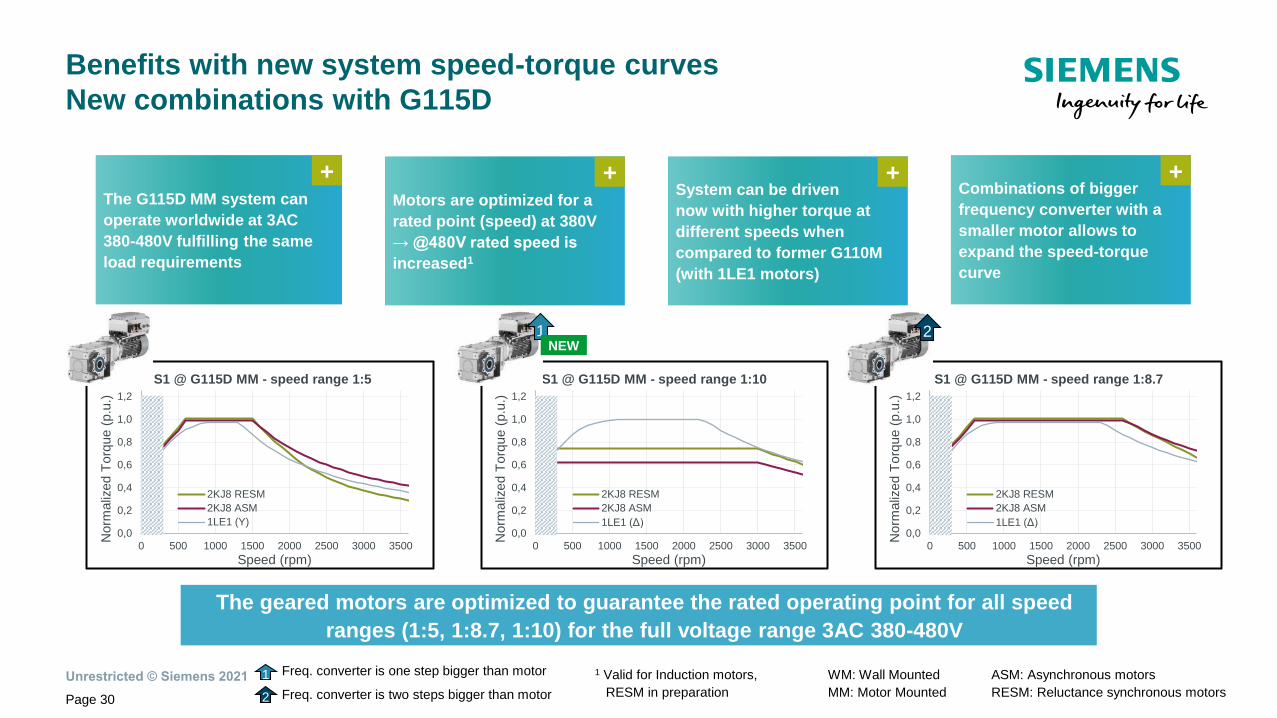
Benefits with new system speed-torque curves
New combinations with G115D
Page 30
The geared motors are optimized to guarantee the rated operating point for all speed
ranges (1:5, 1:8.7, 1:10) for the full voltage range 3AC 380-480V
Combinations of bigger
frequency converter with a
smaller motor allows to
expand the speed-torque
curve
+
WM: Wall Mounted
MM: Motor Mounted
1 Freq. converter is one step bigger than motor
2 Freq. converter is two steps bigger than motor
ASM: Asynchronous motors
RESM: Reluctance synchronous motors
1 Valid for Induction motors,
RESM in preparation
0,0
0,2
0,4
0,6
0,8
1,0
1,2
0 500 1000 1500 2000 2500 3000 3500
Norm
aliz
ed T
orq
ue (
p.u
.)
Speed (rpm)
S1 @ G115D MM - speed range 1:10
2KJ8 RESM
2KJ8 ASM
1LE1 (Δ)0,0
0,2
0,4
0,6
0,8
1,0
1,2
0 500 1000 1500 2000 2500 3000 3500
Norm
aliz
ed T
orq
ue (
p.u
.)
Speed (rpm)
S1 @ G115D MM - speed range 1:8.7
2KJ8 RESM
2KJ8 ASM
1LE1 (Δ)0,0
0,2
0,4
0,6
0,8
1,0
1,2
0 500 1000 1500 2000 2500 3000 3500
Norm
aliz
ed T
orq
ue (
p.u
.)
Speed (rpm)
S1 @ G115D MM - speed range 1:5
2KJ8 RESM
2KJ8 ASM
1LE1 (Y)
1 2NEW
The G115D MM system can
operate worldwide at 3AC
380-480V fulfilling the same
load requirements
+Motors are optimized for a
rated point (speed) at 380V
→ @480V rated speed is
increased1
+System can be driven
now with higher torque at
different speeds when
compared to former G110M
(with 1LE1 motors)
+

Unrestricted © Siemens 2021
Overview of main features from
SIMOGEAR 2KJ3 vs 2KJ8
Page 31
Helical Parallel shaft Bevel Helical worm Monorail Worm Tandem
Gearbox types
19 29 39 49 59 69 79 89 109 129 149 169 189
< 0.25 kW 0.37 – 7.5 kW 9.2 – 55 kW
63 71 80 90 100 112 132 160 180 200 225 250
Asynchronous
for all gearbox FS 19-89
Reluctance
for all gearbox FS 19-89Asynchronous VSD10
IE2 (AH71) IE3/NPE (> AH80) IE4 IE1 IE2 IE3
Motor types
Efficiency
4 2 6 8
Gearbox sizes
[FS]
Motor poles
Motor types
[FS]
G115D [2KJ8]SIMOGEAR [2KJ3 & 2KJ4]
Portfolio available in
NPE: NEMA Premium Efficient
SIMOGEAR overview
Motor types
Gears

Unrestricted © Siemens 2021
The new G115D system (0.37 to 7.5kW) is the successor of
existing portfolio – in FY22 G110M/D will be migratedM
igra
tio
n p
ath
Wall M
ou
nte
d /
Mo
tor
Mo
un
ted
Power range (kW)
0.75 1.1 2.2 3 4 7.55.50.550.37Will be replaced
Page 32
Wall Mounted
Motor Mounted
G115D
IP6
5/6
6
3AC
380 – 480V
I/O ctrl, AS-i,
PN / EtherNet/IP
G110D3AC
380 – 500VIP6
5
AS-i
G110M3AC
380 – 480V
IP6
5/6
6
USS, AS-i, DP,
PN/ EtherNet/IP

Unrestricted © Siemens 2021
Customer
6 S L 3 5 2 x - x X x x x - x A x 0
Article Number
1 2 3 4 5 6 7 8 9 10 11 12 13 14 15 16
7 EM brake options 0: DC 180V; 1: AC 400V
8 User interface0: Blank; 1: Repair switch (RS); 2: Local remote
control (LRC); 3: Both (RS + LRC)
12
13
Power range
0.37 – 7.5 kW / 0.5 – 10 HP
0-3: 0.37 kW
0-5: 0.55 kW
0-7: 0.75 kW
1-1: 1.1 kW
1-5: 1.5 kW
2-2: 2.2 kW
3-0: 3 kW
4-0: 4kW
5-5: 5.5 kW
7-5: 7.5 kW
15 Communication Interface A: AS-Interface; B: I/O control; F: PN/ EtherNet/IP
Digit Description Options
Page 33
The article number structure makes SINAMICS G115D easier
to order with an Out-of-the-Box approach
Wall Mounted version – New ordering method Out-of-the-Box
SINAMICS G115D is ready out
of the box.
Interconnection typeGland version; Connector version (incl. daisy chain
option); mixed version
10
11
Ready
to switch on!

Unrestricted © Siemens 2021
Customer
2 K J 8 x x x - x x x x x - x x x x
Article Number
1 2 3 4 5 6 7 8 9 10 11 12 13 14 15 16
5 Gearbox type, stage (1-3) Helical; Parallel shaft; Bevel; Helical worm, Monorail
15
16Transmission ratio Ratio depending on gearbox type
Digit Description Options
Page 34
The article number structure makes SINAMICS G115D easier
to order with an Out-of-the-Box approach
Motor Mounted version – New ordering method Out-of-the-Box
SINAMICS G115D is ready out
of the box.
8 Motor type ASM High efficiency IE3; RESM Premium efficiency IE4
9 Motor frame size (height) 71; 80; 90; 100; 112
10 Power range 3 types of power range (shorter stator; longer stator)
11 Temperature sensor With temperature sensor Pt1000; without
12 Brake With DC 180V; without
13 G115D power range 0.37 kW … 4 kW / 0.5 … 5 HP
14 G115D comm. Interface AS-Interface; I/O control; PROFINET/ EtherNet/IP
6
7Gearbox size 19 - 89
Ready
to switch on!
ASM: Asynchronous motors
RESM: Reluctance synchronous motors

Unrestricted © Siemens 2021
Fast sizing, selection and ordering process via
broad range of tools
Sizing and configuration via TSTSelection via DT- ConfiguratorSelection via Catalog D 31.2
Convenient, smart and simple sizing of entire system according to your application!
• Easy selection of the entire system
incl. options and supplementary
products
• Allows efficient selection and
configuration of the system (drive +
gear + motor)
• Quick and easy guided system
configuration and ordering process
• Integration of supplementary
products (from Harting, Knorrtec)
Page 35
Unrestricted © Siemens 2021
Page 36
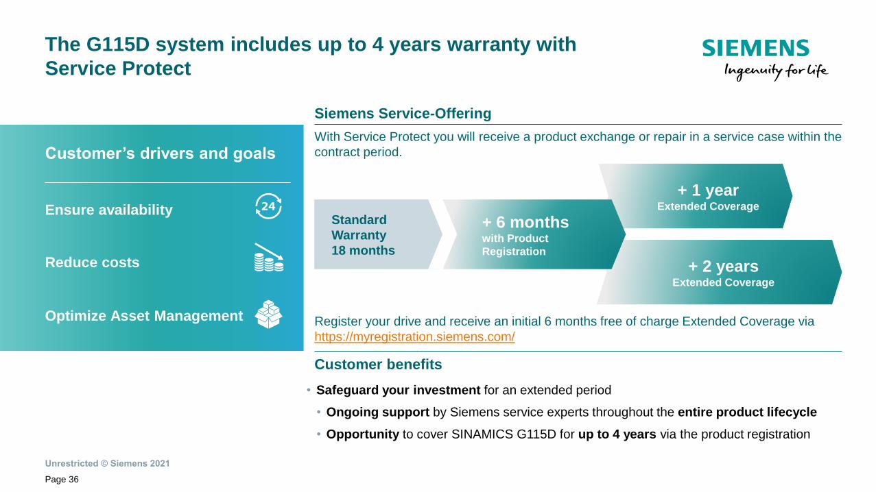
The G115D system includes up to 4 years warranty with
Service Protect
Siemens Service-Offering
Customer benefits
• Safeguard your investment for an extended period
• Ongoing support by Siemens service experts throughout the entire product lifecycle
• Opportunity to cover SINAMICS G115D for up to 4 years via the product registration
Register your drive and receive an initial 6 months free of charge Extended Coverage via
https://myregistration.siemens.com/
With Service Protect you will receive a product exchange or repair in a service case within the
contract period. Customer’s drivers and goals
Ensure availability
Reduce costs
Optimize Asset Management
+ 2 years Extended Coverage
Standard
Warranty
18 months
+ 6 months with Product
Registration
+ 1 year Extended Coverage