single and tandem - danfoss...pump configured with pressure limiter must have pressure limiters on...
TRANSCRIPT
Basic Information
H1 Axial Piston PumpsSingle and Tandem
wwwdanfosscom
Revision history Table of revisions
Date Changed Rev
November 2019 Speed sensor Integral Charge Pressure Filtration data changes 0703
April 2019 CCO topic update 0702
May 2018 Angle sensor for EDC controls added 0701
April 2017 NFPE and AC controls added 0602
May 2016 Updated to Engineering Tomorrow design 0601
Nov 2010-Nov 2015 Various changes BA-0501
Jul 2009 First edition AA
Basic InformationH1 Axial Piston Pumps Single and Tandem
2 | copy Danfoss | November 2019 BC00000057en-000703
Danfoss hydrostatic product familyA word about the organization of this manual 5General description of H1 family hydrostatic pumps5Overview of H1 Pumps Technical Specifications 6H1 Pumps Literature Reference7
OperationPressure Limiter Valves8High Pressure Relief Valve (HPRV) and Charge Check Valve8Bypass Function 9System Schematic for Single Pump 9System Schematic for Tandem Pumps10Charge Pressure Relief Valve (CPRV) 10Electrical Displacement Control (EDC) 11
EDC Operation 11Manual Displacement Control (MDC) 12
MDC Operation12Neutral Start Switch (NSS) 13
Automotive Control (AC) 14Automotive Control connection diagram 15
Forward-Neutral-Reverse (FNR) electric control 16Non Feedback Proportional Electric Control (NFPE) 16Fan Drive Control (FDC) 18
Control Signal Requirements FDC 18Manual Override (MOR) 20Swashplate Angle Sensor for EDC Controls21Swash Plate Angle Sensor for NFPE and AC2 Controls22Control Cut Off Valve (CCO) 23
Brake gauge port with MDC 23Displacement Limiter 24Life Time 24Speed and Temperature Sensor 25
Description25Theory of Operation 25Target Ring25Mating Connectors25Speed Sensor 45 ndash 8 V Technical Data 26Temperature Sensor Data26
Operating ParametersInput Speed28System Pressure28Servo Pressure29Charge Pressure29Charge Pump Inlet Pressure29Case Pressure29External Shaft Seal Pressure 30Temperature 30Viscosity30
System design parametersFluid Specification 31
Fluid selection31Filtration System32Suction Filtration33Charge pressure filtration (full charge pump flow) 33
Remote Charge Pressure Filtration 34Integral Charge Pressure Filtration35H1P Filters Ordering Numbers36Filter Bypass Characteristic37Bypass Sensor Clearance37
Basic InformationH1 Axial Piston Pumps Single and Tandem
Contents
copy Danfoss | November 2019 BC00000057en-000703 | 3
Reservoir38Case drain 38Charge pump39Bearing loads and life 40Mounting flange loads41Shaft Torque for Splined Shafts 42Shaft Torque for Tapered Shafts42Shaft availability and torque ratings43Minimizing System Noise44Determination of Nominal Pump Sizes45
Basic InformationH1 Axial Piston Pumps Single and Tandem
Contents
4 | copy Danfoss | November 2019 BC00000057en-000703
A word about the organization of this manual
General information covering all displacements of the H1 range is given in the beginning of this manualThis includes definitions of operating parameters and system design considerations
The next sections in the book detail the specific operating limitations for each frame and give a fullbreakdown of available displacements features and options
General description of H1 family hydrostatic pumps
The H1 family of closed circuit variable displacement axial piston pumps is designed for use with allexisting Danfoss hydraulic motors for the control and transfer of hydraulic power The H1 axial pistonvariable displacement pumps are of cradle swash-plate design and are intended for closed circuitapplications
Flow direction is reversed by tilting the swash-plate to the opposite side of the neutral (zerodisplacement) position The flow rate is proportional to the pump input speed and displacement Thelatter is infinitely adjustable between zero and maximum displacement
H1 pumps can be used together in combination with other Danfoss pumps and motors in the overallhydraulic systembull Danfoss hydrostatic products are designed with 14 different displacements (cmsup3 [insup3])
045 053 060 068 069 078 089 100 115 130 147 165 210 250
450[275]
538[328]
604[369]
680[415]
690[422]
780[476]
892[544]
1017[621]
1158[707]
1308[798]
1470[897]
1650[1007]
2115[1291]
2517[1536]
bull Danfoss hydrostatic products are designed with many different pressure load-life and controlcapabilities
‒ Electric Displacement Control (EDC)
‒ Forward-Neutral-Reverse control (FNR)
‒ Non-Feedback Proportional Electric control (NFPE)
‒ Automotive Control (AC)
‒ Fan Drive Control (FDC)
‒ Manual Displacement Control (MDC)
‒ Control-Cut-Off valve (CCO)
bull High power density where all units utilize an integral electro-hydraulic servo piston assembly thatcontrols the rate (speed) and direction of the hydraulic flow
bull Compatible with the Danfoss family of PLUS+1reg micro-controllers for easy Plug-and-Performinstallation
bull More compact and lightweight
bull Improved reliability and performance
Go to the Danfoss website or applicable product catalog to choose the components that are right foryour complete closed circuit hydraulic system
Basic InformationH1 Axial Piston Pumps Single and Tandem
Danfoss hydrostatic product family
copy Danfoss | November 2019 BC00000057en-000703 | 5
Overview of H1 Pumps Technical Specifications
The table shows the available range of H1 pumps as of this printing with their respective speed pressureweight and mounting flange
Feature 045 053 060 068 069078 089100 115130 147165 210250
Rated speed min-1 (rpm) 3400 3500 3500 3300 3200 3000 2600
Max speed min-1 (rpm) 3500 4000 4000 3800 3400 3100 2800
Max working pressure bar[psi]1)
420 [6092] 380 [5511] 420 [6092] 380 [5511] 450 [6527] 450 [6527] 450 [6527] 450 [6527] 450 [6527]
Max pressure bar [psi] 450 [6527] 400 [5802] 450 [6527] 400 [5802] 480 [6962] 480 [6962] 480 [6962] 480 [6962] 480 [6962]
Weight dry kg [lb] (withoutPTOfilter)
single 41 [90]tandem 65 [143]
single 50 [110]tandem 962 [212]
56 [123] 62 [137] 83 [187] 96 [211] 163 [360]
Mounting flange SAE B 2-bolt SAE C 4-bolt SAE C 4-bolt
SAE C 4-bolt
SAE D 4-bolt
SAE D 4-bolt
SAE E 4-bolt
1) Applied pressures above maximum working pressure requires Danfoss application approval
Basic InformationH1 Axial Piston Pumps Single and Tandem
Danfoss hydrostatic product family
6 | copy Danfoss | November 2019 BC00000057en-000703
H1 Pumps Literature Reference
Available literature for H1 Pumps
Title Literature Type Number
H1 Axial Piston Pumps Single and Tandem Product Line Overview AM00000001en-00
H1 Axial Piston Pumps Single and Tandem Basic Information BC00000057en-00
H1T 045053060068 Axial Piston Tandem Pumps Technical Information BC00000060en-00
H1P 045053 Axial Piston Single Pumps Technical Information BC00000059en-00
H1P 060068 Axial Piston Single Pumps Technical Information BC00000074en-00
H1P 069078 Axial Piston Single Pumps Technical Information BC00000058en-00
H1P 089100 Axial Piston Single Pumps Technical Information BC00000067en-00
H1P 115130 Axial Piston Single Pumps Technical Information BC00000198en-00
H1P 147165 Axial Piston Single Pumps Technical Information BC00000061en-00
H1P 210250 Axial Piston Single Pumps Technical Information BC00000207en-00
H1P 045053060068 Axial Piston Single Pumps Service Manual AX00000104en-00
H1T 045053060068 Axial Piston Tandem Pumps Service Manual AX00000103en-00
H1P 069ndash250 Axial Piston Single Pumps Service Manual AX00000087en-00
Further available literature
Title Literature Type Number
H1 Pump Electrical Displacement Control (EDC) Electrical Installation BC00000255en-00
H1 Pump 3-position Electric Control (FNR) Electrical Installation BC00000269en-00
H1 Pump Non-Feedback Prop Electric Control (NFPE) Electrical Installation BC00000270en-00
H1 Pump Automotive Control (AC) Technical Information BC00000213en-00
H1 Automotive on PLUS+1 for MC024 Technical Information BC00000201en-00
Speed and Temperature Sensor Technical Information BC00000047en-00
Pressure Sensor Technical Information BC00000178en-00
External Remote Charge Pressure Filter Technical Information BC00000064en-00
Design Guideline for Hydraulic Fluid Cleanliness Technical Information BC00000095en-00
Hydraulic Fluids and Lubricants Technical Information BC00000093en-00
Data sheets for all pump sizes are available
Comprehensive technical literature is online at wwwdanfosscom
Basic InformationH1 Axial Piston Pumps Single and Tandem
Danfoss hydrostatic product family
copy Danfoss | November 2019 BC00000057en-000703 | 7
Pressure Limiter Valves
Pressure limiter valves provide system pressure protection by compensating the pump swash plateposition when the set pressure of the valve is reached A pressure limiter is a non-dissipative (non heatgenerating) pressure regulating system
Each side of the transmission loop has a dedicated pressure limiter valve that is set independently Apump configured with pressure limiter must have pressure limiters on both sides of the system pressureloop The pump order code allows for different pressure settings to be used at each system port
The pressure limiter setting is the maximum differential pressure between the high and low loops Whenthe pressure limiter setting is reached the valve ports oil to the low-pressure side of the servo piston Thechange in servo differential pressure rapidly reduces pump displacement Fluid flow from the valvecontinues until the resulting drop in pump displacement causes system pressure to fall below thepressure limiter setting
An active pressure limiter destrokes a pump to near neutral when the load is in a stalled condition Thepump swash-plate moves in either direction necessary to regulate the system pressure including intostroke (overrunning) or over-center (winch payout)
The pressure limiter is optional on H1 pumps (except H1T 045053 tandem pumps)
High Pressure Relief Valve (HPRV) and Charge Check Valve
All H1 pumps have a combination high pressure relief and charge check valve The high pressure relieffunction is a dissipative (heat generating) pressure control valve for the purpose of limiting excessivesystem pressures The charge check function replenishes the low pressure side of the working loop withcharge oil
Each side of the transmission loop has a dedicated HPRV valve that is non-adjustable with a factory setpressure When system pressure exceeds the factory setting of the valve oil is passed from the highpressure system loop into the charge gallery and into the low pressure system loop via the chargecheck
The pump may have different pressure settings to be used at each system port When an HPRV valve isused in conjunction with a pressure limiter the HPRV valve is always factory set above the setting of thepressure limiter The system pressure shown in the order code for pumps with only HPRV is the HPRVsetting
The system pressure shown in the order code for pumps with pressure limiter and HPRV is a reflection ofthe pressure limiter setting
HPRVs are set at low flow condition Any application or operating condition which leads to elevated HPRVflow will cause a pressure rise with flow above the valve setting Consult factory for application review
Excessive operation of the HPRV will generate heat in the closed loop and may cause damage to theinternal components of the pump
Basic InformationH1 Axial Piston Pumps Single and Tandem
Operation
8 | copy Danfoss | November 2019 BC00000057en-000703
Bypass Function
The bypass function allows a machine or load to be moved without rotating the pump shaft or primemover The single pump HPRV valve also provides a loop bypass function when each of the two HPRV hexplugs are mechanically backed out three full turns
Engaging the bypass function mechanically connects both A amp B sides of the working loop to thecommon charge gallery
Possible damage to hydromotor(s)Excessive speeds and extended loadvehicle movement must be avoided The load or vehicle should bemoved not more than 20 of maximum speed and for a duration not exceeding 3 minutes When thebypass function is no longer needed care should be taken to re-seat the HPRV hex plugs to the normaloperating position
Bypass function not available for tandem pumps
System Schematic for Single Pump
The schematic below shows the function of an H1P axial piston variable displacement pump with electricdisplacement control (EDC)
A
B
MA
S
M3
C2C1
M4
M5
MBL4
L2
M6 1 2
R2
R1M14
F00B F00A
CW
P003 418E
Basic InformationH1 Axial Piston Pumps Single and Tandem
Operation
copy Danfoss | November 2019 BC00000057en-000703 | 9
System Schematic for Tandem Pumps
The schematic below shows the function of H1T axial piston variable displacement tandem pumps withelectric displacement control (EDC)
System schematic tandem pumps
C1 C1 C2C2
M14 M14
CW
F00B F00AF00B F00A
A BMA E C D MD
MB M3
L3
MC
M4
M5M4
M5PTO
X7
P003 207E
Charge Pressure Relief Valve (CPRV)
The charge pressure relief valve is a direct acting poppet valve that opens and discharges fluid to thepump case when pressure exceeds a designated level The charge pressure relief valve maintains chargepressure at a designated level above case pressure
This level is nominally set with the pump running at 1800 min-1(rpm) and with a fluid viscosity of 32mmsup2s [150 SUS] In forward or reverse charge pressure will be slightly lower than in neutral position Themodel code of the pump specifies the charge pressure relief valve setting Typical charge pressureincrease from 12-15 bar per 10 lmin [174-218 psi per 264 US galmin] For external charge flow theCPRV is set according to the table below
Standard level setting is ∆p = 21 plusmn 11 bar [304 plusmn 16 psi] with the pump running at 1500 min-1(rpm) andflow = 2380 - 295 lmin [ 63 - 78 US galmin] Typical charge pressure increase is 2 bar per 10 lmin [29psi per 264 US galmin]
CPRV flow setting for external charge supply
Tandem 045053 Single 045053 Single 060mdash165 Single 210250
30 lmin [79 US galmin] 15 lmin [39 US galmin] 227 lmin [60 US galmin] 400 lmin [106 US galmin]
Charge pressure relief valve
Basic InformationH1 Axial Piston Pumps Single and Tandem
Operation
10 | copy Danfoss | November 2019 BC00000057en-000703
Electrical Displacement Control (EDC)
An EDC is a displacement (flow) control Pump swash plate position is proportional to the inputcommand and therefore vehicle or load speed (excluding influence of efficiency) is dependent only onthe prime mover speed or motor displacement
The Electrical Displacement Control (EDC) consists of a pair of proportional solenoids on each side of athree-position four-way porting spool The proportional solenoid applies a force input to the spoolwhich ports hydraulic pressure to either side of a double acting servo piston Differential pressure acrossthe servo piston rotates the swash plate changing the pumplsquos displacement from full displacement inone direction to full displacement in the opposite direction
A serviceable 125 μm screen is located in the supply line immediately before the control porting spool
Under some circumstances such as contamination the control spool could stick and cause the pump tostay at some displacement
Electrical Displacement Control
P003 191
EDC schematic feedback from swash plate
Feedback from Swash plate
PTF00B
M14
C1 C2
F00A
P003 478E
EDC Operation
H1 EDCrsquos are current driven controls requiring a Pulse Width Modulated (PWM) signal Pulse widthmodulation allows more precise control of current to the solenoids
The PWM signal causes the solenoid pin to push against the porting spool which pressurizes one end ofthe servo piston while draining the other Pressure differential across the servo piston moves theswashplate
A swashplate feedback link opposing control links and a linear spring provide swashplate position forcefeedback to the solenoid The control system reaches equilibrium when the position of the swashplatespring feedback force exactly balances the input command solenoid force from the operator Ashydraulic pressures in the operating loop change with load the control assembly and servoswashplatesystem work constantly to maintain the commanded position of the swashplate
The EDC incorporates a positive neutral deadband as a result of the control spool porting preloads fromthe servo piston assembly and the linear control spring Once the neutral threshold current is reachedthe swashplate is positioned directly proportional to the control current To minimize the effect of thecontrol neutral deadband we recommend the transmission controller or operator input deviceincorporate a jump up current to offset a portion of the neutral deadband
The neutral position of the control spool does provide a positive preload pressure to each end of theservo piston assembly
When the control input signal is either lost or removed or if there is a loss of charge pressure the spring-loaded servo piston will automatically return the pump to the neutral position
Basic InformationH1 Axial Piston Pumps Single and Tandem
Operation
copy Danfoss | November 2019 BC00000057en-000703 | 11
Manual Displacement Control (MDC)
A Manual proportional Displacement Control (MDC) consists of a handle on top of a rotary input shaftThe shaft provides an eccentric connection to a feedback link This link is connected on its one end with aporting spool On its other end the link is connected the pumps swashplate
This design provides a travel feedback without spring When turning the shaft the spool moves thusproviding hydraulic pressure to either side of a double acting servo piston of the pump
Differential pressure across the servo piston rotates the swash plate changing the pumprsquos displacementSimultaneously the swashplate movement is fed back to the control spool providing proportionalitybetween shaft rotation on the control and swash-plate rotation The MDC changes the pumpdisplacement between no flow and full flow into opposite directions
Under some circumstances such as contamination the control spool could stick and cause the pump tostay at some displacement
For the MDC with CCO option the brake port (X7) provides charge pressure when the coil is energized toactivate static function such as a brake release The X7 port must not be used for any continuous oilconsumption
The MDC is sealed by means of a static O-ring between the actuation system and the control block Itsshaft is sealed by means of a special O-ring which is applied for low friction The special O-ring isprotected from dust water and aggressive liquids or gases by means of a special lip seal
Manual Displacement Control Pump displacement vs control lever rotation
0Lever rotationA
Dis
plac
emen
t
100
a
-a
100
B-b-d
b c
d
-c
P301 752
Deadband on B side a = 3deg plusmn1degMaximum pump stroke b = 30deg +2-1degRequired customer end stop c = 36deg plusmn3degInternal end stop d = 40deg
MDC Operation
The MDC provides a mechanical dead-band required to overcome the tolerances in the mechanicalactuation The MDC contains an internal end stop to prevent turning the handle into any inappropriateposition
The MDC provides a permanent restoring moment appropriate for turning the MDC input shaft back toneutral position only This is required to take the backlash out of the mechanical connections betweenthe Bowden cable and the control
C Caution
High case pressure may cause excessive wear and the NSS to indicate that the control is not in neutralposition In addition if the case pressure exceeds 5 bar there is a risk of an insufficient restoring momentThe MDC is designed for a maximum case pressure of 5 bar and a rated case pressure of 3 bar
Basic InformationH1 Axial Piston Pumps Single and Tandem
Operation
12 | copy Danfoss | November 2019 BC00000057en-000703
bull Customers must install some support to limit the setting range of their Bowden cable to avoid anoverload of the MDC
bull Customers can apply their own handle design but they must care about a robust clampingconnection between their handle and the control shaft and avoid overload of the shaft
bull Customers can connect two MDCrsquos on a tandem unit in such a way that the actuation force will betransferred from the pilot control to the second control The kinematic of the linkages must ensurethat either control shaft is protected from torque overload
C Caution
Using the internal spring force on the input shaft is not an appropriate way to return the customerconnection linkage to neutral or to force a Bowden cable or a joystick back to neutral position It is notapplicable for any limitation of the Bowden cable stroke except the applied torque to the shaft will neverexceed 20 Nbullm
Neutral Start Switch (NSS)
The Neutral Start Switch (NSS) contains an electrical switch that provides a signal of whether the controlis in neutral The signal in neutral is Normally Closed (NC)
Neutral Start Switch schematic
P005 702
M14
M5 M4 M3
Neutral Start Switch data
Max continuous current with switching 84 A
Max continuous current without switching 20 A
Max voltage 36 VDC
Electrical protection class IP67 IP69K with mating connector
Basic InformationH1 Axial Piston Pumps Single and Tandem
Operation
copy Danfoss | November 2019 BC00000057en-000703 | 13
Automotive Control (AC)
The AC-1 and AC-2 propel transmission system consists of an H1 variable pump embedded electroniccontroller and service tool configurable PLUS+1reg software that allows the customer to completelyoptimize vehicle performance
The embedded electronic controller provides an electric input signal activating one of two solenoids thatport charge pressure to either side of the pump servo cylinder The AC-1 has no mechanical feedbackmechanism but AC-2 is available with an electronic feedback signal for the swashplate position AC-2 isan extension of AC-1 that features an integrated pump swashplate angle sensor and software enabledfunctions such as swashplate control
The pump displacement is proportional to the solenoid signal current but it also depends upon pumpinput speed and system pressure This characteristic also provides a power limiting function by reducingthe pump swash plate angle as system pressure increases A typical response characteristic is shown inthe accompanying graph
A serviceable 170 μm screen is located in the supply line immediately before the control porting spool
Under some circumstances such as contamination the control spool could stick and cause the pump tostay at some displacement
Automotive Control (AC)
P003 544
CAN
PPCPSC
PPUCC2
CC1
WA
RRAN
TY VOID
IF REMO
VED
CC3
Automotive Control (AC) schematic
P301 236
C2C1
F00A T PF00B
Basic InformationH1 Axial Piston Pumps Single and Tandem
Operation
14 | copy Danfoss | November 2019 BC00000057en-000703
Automotive Control connection diagram
Batt1224V DC
+ -
S 11
F 1
2
TerminalsBatt (+)
TerminalsBatt (-)
123456
DEUTSCH connectorDTM6 pin
Sensor A (+)Analog Input ASensor A (-)Sensor B (-)
PPC
Analog Input BSensor B (+)
123
DEUTSCH connectorDTM3 pin
CAN HighCAN LowCAN Shield
CAN
123456
DEUTSCH connectorDTM6 pin
PWM C1 (+)PWM C2 (+)Digital Output A1 (+)Digital Output A2 (-)
PSC
PWM C2 (-)PWM C1 (-)
123
DEUTSCH connectorDTM3 pin
Sensor (+)Pump RPM Input (Frequency)Sensor (-)
PPU
TerminalsSensor (-)
TerminalsSensor (+)
CC1p01
CC1p02
CC1p03
CC1p04Motor RPMDirection
CC1p05
123456789
101112
DEUTSCH connector DTM12 pin
Inch Input (Analog-Red)Mode Switch B Input (Digital-Nom)Motor PROPPCOR Output (PWM)Motor Direction Input (Analog)Sensor (+)Sensor (-)Inch Input (Analog-Nom)Motor BPD Output (Digital)Digital Output B2 (-)Digital Output B1 (+)Mode Switch A Input (Digital)Mode Switch B Input (Digital-Red)
CC2
123456789
101112
DEUTSCH connectorDTM12 pin
Battery (-) Battery (+)Sensor (+) Sensor (-)Motor RPM Input (Frequency)Forward Input (Digital)Reverse Input (Digital)Sensor (+) Sensor (-)Drive Pedal Input (Analog-Nom)Drive Pedal Input (Analog-Red)Neutral Input (Digital)
CC1
CC2p04
CC1p06
CC1p07
CC1p12
egHand BrakeSeat-Switch
FNR SwitchCC1p08
CC1p09
Rv
Rv
DriveCreepJoystickRocker Pedal
CC1p10
CAN BusCANp01
CANp02
CANp03
PSCp01
PSCp06PSCp03
PSCp04PSCp02
PSCp05
C 1
C 2
Electronic Displacement Control Pump
Pump RPMPPUp02
PPUp03
PPUp01
Mode Switch BCC2p02
2-P
BPD
PROP
CC2p03
CC2p03
CC2p08
CC2p05
CC2p06
Electronic Displacement Control Motor
Rv
Rv
Inch PedalCC2p07
Alternative Brake Pressure Inch Sensor
Reverse Motion
ParkingBrake
CC2p11
CC2p10
CC2p09
CC1p03
CC1p04
CC1p08
CC1p09
PPUp01
PPUp03
CC2p05
CC2p06
CC2p01
CC2p12
CNT
B
A
CC1p11
Mode Switch A
FNR in Reverse
BrakeLight
FaultLED
Vehicle-Speed-DependentOutput-Signal
ReverseLED
BrakeLight
FNR in Reverse
FaultLED
ForwardLED
BrakeLight
3
Nominal
Redundant
3
Reverse Motion
FNR in Reverse
1
2
DEUTSCH connectorDT2 pin
CC3
CC3p01
CC3p02
3
2
1 Contact capability min 10A
Melting fuse 16A
Functional optionsP003 536E
Basic InformationH1 Axial Piston Pumps Single and Tandem
Operation
copy Danfoss | November 2019 BC00000057en-000703 | 15
Forward-Neutral-Reverse (FNR) electric control
The 3-Position (F-N-R) control uses an electric input signal to switch the pump to a full stroke position
A serviceable 125 μm screen is located in the supply line immediately before the control porting spool
Under some circumstances such as contamination the control spool could stick and cause the pump tostay at some displacement
FNR control
P003 193
3-Position electric control hydraulic schematic
P003 189
C2C1
F00A
M14
T PF00B
Non Feedback Proportional Electric Control (NFPE)
The Non Feedback Proportional Electric (NFPE) control is an electrical automotive control in which anelectrical input signal activates one of two proportional solenoids that port charge pressure to either sideof the pump servo cylinder The NFPE control has no mechanical feedback mechanism
A serviceable 170 μm screen is located in the supply line immediately before the control porting spool
Under some circumstances such as contamination the control spool could stick and cause the pump tostay at some displacement
Non Feedback Proportional Electric Control
P003 192
NFPE schematic
P003 188
C2C1
F00A
M14
T PF00B
The pump displacement is proportional to the solenoid signal current but it also depends upon pumpinput speed and system pressure This characteristic also provides a power limiting function by reducing
Basic InformationH1 Axial Piston Pumps Single and Tandem
Operation
16 | copy Danfoss | November 2019 BC00000057en-000703
the pump swashplate angle as system pressure increases A typical response characteristic is shown inthe accompanying graph Under some circumstances such as contamination the control spool couldstick and cause the pump to stay at some displacement
NFPE pump displacement to Input signal
0
Signal Current mA(DC)
a b c
abc
Dis
plac
emen
t
100
100
NFPE control
∆p =
300
bar
∆p =
300
bar
∆p =
0 b
ar
∆p =
0 b
ar
P003 187E
Basic InformationH1 Axial Piston Pumps Single and Tandem
Operation
copy Danfoss | November 2019 BC00000057en-000703 | 17
Fan Drive Control (FDC)
The Fan Drive Control (FDC) is a non-feedback control in which an electrical input signal activates theproportional solenoid that ports charge pressure to either side of the pump servo cylinder The singleproportional solenoid is used to control pump displacement in the forward or reverse direction
The control spool is spring biased to produce maximum forward pump displacement in the absence ofan electrical input signal Based on the spring bias spool default forward flow for a CW rotation pump isout of port B while default forward flow for a CCW rotation pump is out of port A
Under some circumstances such as contamination the control spool could stick and cause the pump tostay at some displacement
FDC control
P301 441
FDC schematic
PTF00B
M14
C1 C2
F00A P301 442
The pump should be configured with 08 mm control orifices to provide slowest response and maximizesystem stability Additionally pressure limiter (PL) valves are used to limit maximum fan trim speed inboth (forward and reverse) directions
H1 pumps with FDC will be delivered from factory with nominal pressure limiter setting of 150 bar [2175psi] The PL must be re-adjusted to ensure that the fan reaches the desired fan speed to satisfy thecooling needs of the system HPRV setting must be always at least 30 bar [435 psi] higher than PL setting
For more information necessary to properly size and configure a hydraulic fan drive system see HydraulicFan Drive Design Guidelines AB00000019
W Warning
Use in other systems could result in unintended movement of the machine or itrsquos elements Loss of theinput signal to this control will cause the pump to produce maximum flowThe FDC is for Fan Drive systems only
Due to the fail-safe functionality of the FDC control the pump will stroke to max displacement in case theinput signal to the pump control and the Diesel engine will be switched off at the same time In thissituation a low loop event can occur which may damage the pump Therefore itrsquos strictly recommendedto keep the input signal to the pump control alive while switching off the engineFor further information please contact your Danfoss representative
Control Signal Requirements FDC
The pump displacement is proportional to the solenoid signal current but it also depends upon pumpinput speed and system pressure This characteristic also provides a power limiting function by reducing
Basic InformationH1 Axial Piston Pumps Single and Tandem
Operation
18 | copy Danfoss | November 2019 BC00000057en-000703
the pump swash plate angle as system pressure increases A typical response characteristic is shown inthe accompanying graph below
100
100
Dis
plac
emen
t
0 Signal current (mA(DC Avg))
Max current
Na
b
∆p = 0 bar
∆p = 0 bar
∆p = 300 bar
Reverse
Forward
a ndash Forward thresholdb ndash Reverse thresholdN ndash Neutral override current
Control current requirements
Voltage a N b Pin config
12 VDC 780 mA 1100 mA 1300 mAany order
24 VDC 400 mA 550 mA 680 mA Factory test current for fan movement expect higher or lower value
Basic InformationH1 Axial Piston Pumps Single and Tandem
Operation
copy Danfoss | November 2019 BC00000057en-000703 | 19
Manual Override (MOR)
All controls are available with a manual override functionality either as a standard or as an option fortemporary actuation of the control to aid in diagnostics
Control with manual override
P003 204
MOR schematic (EDC control shown)
PTF00B
M14
C2C1
F00A
Feedback from swash plate
The MOR plunger has a 4 mm diameter and must be manually depressed to be engaged Depressing theplunger mechanically moves the control spool which allows the pump to go on stroke The MOR shouldbe engaged anticipating a full stroke response from the pumpAn o-ring seal is used to seal the MOR plunger where initial actuation of the function will require a forceof 45 N to engage the plunger Additional actuation typically require less force to engage the MORplungerProportional control of the pump using the MOR should not be expected
W Warning
Unintended MOR operation will cause the pump to go into stroke example vehicle lifted off the groundThe vehicle or device must always be in a safe condition when using the MOR function
Refer to control flow table for the relationship of solenoid to direction of flow
Basic InformationH1 Axial Piston Pumps Single and Tandem
Operation
20 | copy Danfoss | November 2019 BC00000057en-000703
Swashplate Angle Sensor for EDC Controls
The angle sensor detects the swash plate position with an accuracy dependent upon the calibrationeffort done for the application and direction of rotation from the neutral position At minimum the sensorcan be used for forward neutral and reverse (FNR) detection
The sensor works on the hall-effect technology The implemented technology is based on ameasurement of the magnetic field direction in parallel to the chip surface This field direction isconverted to a voltage signal at the output
Enhanced calibration of the non-linear behavior leads to more exact calculation of the pump swashplateangle The 4-pin DEUTSCH connector is part of the sensor housing The swashplate angle sensor isavailable for all EDC controls for 12 V and 24 V
Swashplate angle vs output of supply voltage
-18deg -13deg -8deg
100
90
80
70
60
50
40
30
20
10
0
Swashplate angle
Sens
or o
utpu
t
of s
uppl
y vo
ltage
-3deg 0deg 2deg 7deg 12deg 17deg
W Warning
Strong magnetic fields in the proximity of the sensor can influence the sensor signal and must beavoided
Contact your Danfoss representative in case the angle sensor will be used for safety functions
Basic InformationH1 Axial Piston Pumps Single and Tandem
Operation
copy Danfoss | November 2019 BC00000057en-000703 | 21
Swash Plate Angle Sensor for NFPE and AC2 Controls
The angle sensor detects the swash plate angle position and direction of rotation from the zero positionThe swash angle sensor works on the AMR sensing technology Under the saturated magnetic field theresistance of the element varies with the magnetic field direction
The output signal give a linear output voltage for the various magnet positions in the sensing range
P301 750
Swash plate angle vs output voltage
-25deg -20deg -15deg -10deg -5deg 0deg 5deg 10deg 15deg 20deg 25deg
5
45
4
35
3
25
2
15
1
05
0
Swashplate angle
Out
put v
olta
ge
(V
)
12
Basic InformationH1 Axial Piston Pumps Single and Tandem
Operation
22 | copy Danfoss | November 2019 BC00000057en-000703
Control Cut Off Valve (CCO)
The H1 pump offers an optional control cut off valve integrated into the control All EDC NFPE and MDCcontrols are available with a CCO valve This valve will block charge pressure to the control allowing theservo springs to de-stroke both pumps regardless of the pumpacutes primary control input
There is also a hydraulic logic port X7 which can be used to control other machine functions such asspring applied pressure release brakes The pressure at X7 is controlled by the control cut off solenoidThe X7 port would remain plugged if not needed
In the normal (de-energized) state of the solenoid charge flow is prevented from reaching the controls Atthe same time the control passages and the X7 logic port are connected and drained to the pump caseThe pump will remain in neutral or return to neutral independent of the control input signal Return toneutral time will be dependent on oil viscosity pump speed swashplate angle and system pressure
When the solenoid is energized charge flow and pressure is allowed to reach the pump control The X7logic port will also be connected to charge pressure and flow
The solenoid control is intended to be independent of the primary pump control making the control cutoff an override control feature It is however recommended that the control logic of the CCO valve bemaintained such that the primary pump control signal is also disabled whenever the CCO valve is de-energized Other control logic conditions may also be considered
The CCO valve is available with 12 V or 24 V solenoid
The response time of the unit depends on the control type and the used control orifices
CCO schematic (MDC shown)
P005 703
M14 X7
Brake gauge port with MDC
C Caution
It is not recommended to use brake port for any external flow consumption to avoid malfunction of CCOfunction
Basic InformationH1 Axial Piston Pumps Single and Tandem
Operation
copy Danfoss | November 2019 BC00000057en-000703 | 23
Displacement Limiter
H1 pumps are designed with optional mechanical displacement (stroke) limiters factory set to maxdisplacement The maximum displacement of the pump can be set independently for forward andreverse using the two adjustment screws to mechanically limit the travel of the servo piston down to 50displacement
Adjustments under operating conditions may cause leakage The adjustment screw can be completelyremoved from the threaded bore if backed out to far
P003 266
Life Time
Hydraulic unit life depends on the speed and normal operating or weighted average pressure that canonly be determined from a duty cycle analysis
The life of the product depends on several factors such as speed pressure swash plate angle to name afew
For detailed product life calculation please contact your Danfoss representative
Basic InformationH1 Axial Piston Pumps Single and Tandem
Operation
24 | copy Danfoss | November 2019 BC00000057en-000703
Speed and Temperature Sensor
Description
Function of the speed sensor is to detect the shaft speed Typically the sensor is mounted to the housingof a Danfoss pump or motor and senses the speed from a target ring that is rotating inside the pump ormotor
Because of the digital output signals for speed the sensor is ideal for high and low speed measurements
The speed sensor is designed for rugged outdoor mobile or heavy industrial speed sensing applications
The detection of the speed is contactless It is custom-designed for Danfoss It is a Plug and Perform devicethat does not need any calibration or adjustments
For diagnostics and other purposes some sensor also has the capability to detect the driving directionand the case oil temperature
Theory of Operation
The speed sensor is externally powered and in response to the speed of the target ring outputs a digitalpulse signal A magnet inside the sensor provides the magnetic field that changes with the position ofthe target teeth
The target ring is attached to the cylinder block or the shaft Hall sensors change from highlow state asthe target teeth pass by the sensoracutes face The digital (on-off-on-off ) pulse train is fed to a controllerwhich interprets its rate of change as a speed
Some speed sensor uses two Hall sensors with specific distance and orientation resulting in a pulse trainoutput shift of 90deg between the two sensors A logic circuit decodes the two signals to provide anadditional direction indication (high or low depending on direction)
Due to the design of the sensor the duty cycle (ratio between on and off time at constant speed) of bothspeed signals at any working condition is close to 50 and can be used for better resolution at lowspeeds
Target Ring
Speed (target) rings vary according to the diameter of the cylinder block or shaft on which they areinstalled The number of teeth is shown in the table below
The number of speed (target) ring teeth
H1P size 045053 060068 069078 089100 115130 147165 210250
Teeth 79 86 86 92 102 108 90
Mating Connectors
Mating connectors ordering data
Ordering data
Description Quantity Ordering number
Mating connector 1 DEUTSCH DT06-6S
Wedge lock 1 DEUTSCH WM65
Socket contact (16 and 18 AWG) 6 DEUTSCH 0462-201-2031
DEUTSCH mating connector kit 1 11033865
Basic InformationH1 Axial Piston Pumps Single and Tandem
Operation
copy Danfoss | November 2019 BC00000057en-000703 | 25
Speed Sensor 45 ndash 8 V Technical Data
Speed sensor connector 6-pin
4
3 2 1
5 6
P006035
1 Speed signal 22 Direction signal3 Speed signal 14 Supply5 Ground6 Temperature
Technical data
Parameter Min Nom Max Note
Supply voltage 45 VDC 5 VDC 8 VDC Regulated supply voltageReverse polarity protected
Supply protection ndash ndash 30 VDC Shuts off above 9 V
Max required supply current ndash ndash 25 mA At supply voltage
Max output current ndash ndash 50 mA
Operation mode NPN amp PNP Push-Pull amplifier
Temperature signal -40degC = 2318V ndash 100degC = 0675V
Output low speed signal 5 85 12 Ratiometric output voltageLow state gt 0 V to provide wirefault detection
Output high speed signal 88 915 95
Detectable frequency range 1 Hz ndash 10 000 Hz
Ordering number 149055
Color of connector Black
Temperature Sensor Data
For calculation of the case fluid temperature and the output signal voltage see the formulas below
VO ndash Measured output voltage (V)
Vo= (-388 bull 10-6 bull T2) + (-115 bull 10-2 bull T) + 18639
T ndash Temperature (degC)
T = ndash148196 + radic 21962 106 + (18639 ndash Vordm)388 10-6
Output signal voltage vs Temperature
Temperature range
-55 degC -40 degC -30 degC 0 degC +30 degC +80 degC +100 degC +130 degC
2485 V 2318 V 2205 V 1864 V 1515 V 0919 V 0675 V 0303 V Accuracy plusmn1 5 to plusmn 4 degC Accuracy plusmn25 to plusmn 5 degC
Basic InformationH1 Axial Piston Pumps Single and Tandem
Operation
26 | copy Danfoss | November 2019 BC00000057en-000703
Response time in fluid
T90 definition
00
10
20
30
40
50
60
70
80
90
-100 100 200 300 400 500 600 700 800 900 1000P003531E
Real temperatureTemperatureSignal
T90 definition
T90
Time (S)
Tem
pera
ture
(degC)
90
of ∆
Tem
p
∆ T
emp
Response time in fluid (T90) = 360 s
Basic InformationH1 Axial Piston Pumps Single and Tandem
Operation
copy Danfoss | November 2019 BC00000057en-000703 | 27
Input Speed
Minimumspeed
is the lowest input speed recommended during engine idle condition Operating belowminimum speed limits the pumprsquos ability to maintain adequate flow for lubrication andpower transmission
Rated speed is the highest input speed recommended at full power condition Operating at orbelow this speed should yield satisfactory product life
Operating conditions between rated and maximum speed should be restricted to lessthan full power and to limited periods of time
Maximumspeed
is the highest operating speed permitted Exceeding maximum speed reduces productlife and can cause loss of hydrostatic power and braking capacity For most drivesystems maximum unit speed occurs during downhill braking or negative powerconditions
W Warning
Never exceed the maximum speed limit under any operating conditions
During hydraulic braking and downhill conditions the prime mover must be capable of providingsufficient braking torque in order to avoid pump over speed This is especially important to consider forturbo-charged and Tier 4 engines
For more information please see Pressure and Speed Limits BLN-9884 when determining speed limits fora particular application
System Pressure
Hydraulic unit life depends on the speed and normal operating mdash or weighted average mdash pressure thatcan only be determined from a duty cycle analysis
System pressure is the differential pressure between high pressure system ports It is the dominantoperating variable affecting hydraulic unit life High system pressure which resultsfrom high load reduces expected life
Applicationpressure
is the high pressure relief or pressure limiter setting normally defined within theorder code of the pump This is the applied system pressure at which the drive linegenerates the maximum calculated pull or torque in the application
Maximumworkingpressure
is the highest recommended application pressure and is not intended to be acontinuous pressure Propel systems with application pressures at or below thispressure should yield satisfactory unit life given proper component sizingApplication pressures above maximum working pressure will only be consideredwith duty cycle analysis and factory approval
Pressure spikes are normal and must be considered when reviewing maximumworking pressure
Maximumpressure
is the highest intermittent pressure allowed under any circumstances Applicationswith applied pressures between rated and maximum require factory approval withcomplete application duty cycle and life expectancy analysis
Minimum lowloop pressure
must be maintained under all operating conditions to avoid cavitation
All pressure limits are differential pressures referenced to low loop (charge) pressureSubtract low loop pressure from gauge readings to compute the differential
Basic InformationH1 Axial Piston Pumps Single and Tandem
Operating Parameters
28 | copy Danfoss | November 2019 BC00000057en-000703
Servo Pressure
Servo pressure is the pressure in the servo system needed to position and hold the pump on stroke Itdepends on system pressure and speed At minimum servo pressure the pump will run at reduced strokedepending on speed and pressure
Minimum servo pressure at corner power holds the pump on full stroke at max speed and maxpressure
Maximum servo pressure is the highest pressure typically given by the charge pressure setting
Charge Pressure
An internal charge relief valve regulates charge pressure Charge pressure supplies the control withpressure to operate the swashplate and to maintain a minimum pressure in the low side of thetransmission loop
The charge pressure setting listed in the order code is the set pressure of the charge relief valve with thepump in neutral operating at 1800 min-1 (rpm) and with a fluid viscosity of 32 mm2s [150 SUS]
Pumps configured with no charge pump (external charge supply) are set with a charge flow of 30 lmin[793 US galmin] and a fluid viscosity of 32 mm2s [150 SUS]
The charge pressure setting is referenced to case pressure Charge pressure is the differential pressureabove case pressure
Minimumchargepressure
is the lowest pressure allowed to maintain a safe working condition in the low side ofthe loop Minimum control pressure requirements are a function of speed pressureand swashplate angle and may be higher than the minimum charge pressure shownin the Operating parameters tables
Maximumchargepressure
is the highest charge pressure allowed by the charge relief adjustment and whichprovides normal component life Elevated charge pressure can be used as asecondary means to reduce the swashplate response time
Charge Pump Inlet Pressure
At normal operating temperature charge inlet pressure must not fall below rated charge inlet pressure(vacuum)
Minimum charge inletpressure
is only allowed at cold start conditions In some applications it isrecommended to warm up the fluid (eg in the tank) before starting theengine and then run the engine at limited speed
Maximum charge inletpressure
may be applied continuously
Case Pressure
Under normal operating conditions the rated case pressure must not be exceeded During cold start casepressure must be kept below maximum intermittent case pressure Size drain plumbing accordingly
The auxiliary pad cavity of axial pumps configured without integral charge pumps is referenced to casepressure Units with integral charge pumps have auxiliary mounting pad cavities referenced to chargeinlet (vacuum)
Possible component damage or leakageOperation with case pressure in excess of stated limits may damage seals gaskets andor housingscausing external leakage Performance may also be affected since charge and system pressure areadditive to case pressure
Basic InformationH1 Axial Piston Pumps Single and Tandem
Operating Parameters
copy Danfoss | November 2019 BC00000057en-000703 | 29
External Shaft Seal Pressure
In certain applications the input shaft seal may be exposed to external pressure In order to preventdamage to the shaft seal the maximum differential pressure from external sources must not exceed 04bar (58 psi) over pump case pressure
The case pressure limits of the pump must also be followed to ensure the shaft seal is not damaged
C Caution
Regardless of the differential pressure across the shaft seal the shaft seal has been known to pump oilfrom the external source (e g gear box) into the pump case
Temperature
The high temperature limits apply at the hottest point in the transmission which is normally the motorcase drain The system should generally be run at or below the quoted rated temperature
The maximum intermittent temperature is based on material properties and should never beexceeded
Cold oil will generally not affect the durability of the transmission components but it may affect theability of oil to flow and transmit power therefore temperatures should remain 16 degC [30 degF] above thepour point of the hydraulic fluid
The minimum temperature relates to the physical properties of component materials
Size heat exchangers to keep the fluid within these limits Danfoss recommends testing to verify thatthese temperature limits are not exceeded
Viscosity
For maximum efficiency and bearing life ensure the fluid viscosity remains in the recommended range
The minimum viscosity should be encountered only during brief occasions of maximum ambienttemperature and severe duty cycle operation
The maximum viscosity should be encountered only at cold start
Basic InformationH1 Axial Piston Pumps Single and Tandem
Operating Parameters
30 | copy Danfoss | November 2019 BC00000057en-000703
Fluid Specification
Viscosity
Intermittent1) 5 mm2s [42 SUS]
Minimum 7 mm2s [49 SUS]
Recommended range 12 ndash 80 mm2s [66 ndash 370 SUS]
Maximum 1600 mm2s [7500 SUS]
1) Intermittent = Short term t lt 1 min per incident and not exceeding 2 of duty cycle based load-life
Temperature
Minimum 1) -40degC [-40degF]
Rated 104degC [220degF]
Recommended range2) 60 ndash 85degC [140 ndash 185degF]
Maximum Intermittent 115degC [240degF]
1) Cold start = Short term t gt 3 min p le 50 bar [725 psi] n le 1000 min-1 (rpm)2) At the hottest point normally case drain port
Fluid selection
Ratings and performance data are based on operating with hydraulic fluids containing oxidation rustand foam inhibitors These fluids must possess good thermal and hydrolytic stability to prevent wearerosion and corrosion of pump components
C Caution
Never mix hydraulic fluids of different types
Basic InformationH1 Axial Piston Pumps Single and Tandem
System design parameters
copy Danfoss | November 2019 BC00000057en-000703 | 31
Filtration System
To prevent premature wear ensure only clean fluid enters the hydrostatic transmission circuit A filtercapable of controlling the fluid cleanliness to ISO 4406 class 221813 (SAE J1165) or better under normaloperating conditions is recommended
These cleanliness levels can not be applied for hydraulic fluid residing in the component housingcase orany other cavity after transport
The filter may be located on the pump (integral) or in another location (remote) The integral filter has afilter bypass sensor to signal the machine operator when the filter requires changing Filtration strategiesinclude suction or pressure filtration
The selection of a filter depends on a number of factors including the contaminant ingression rate thegeneration of contaminants in the system the required fluid cleanliness and the desired maintenanceinterval Filters are selected to meet the above requirements using rating parameters of efficiency andcapacity
Filter efficiency can be measured with a Beta ratio (βX) For simple suction filtered closed circuittransmissions and open circuit transmissions with return line filtration a filter with a β-ratio within therange of β35-45 = 75 (β10 ge 2) or better has been found to be satisfactory
For some open circuit systems and closed circuits with cylinders being supplied from the same reservoira considerably higher filter efficiency is recommended This also applies to systems with gears or clutchesusing a common reservoir
For these systems a charge pressure or return filtration system with a filter β-ratio in the range of β15-20 =75 (β10 ge 10) or better is typically required
Because each system is unique only a thorough testing and evaluation program can fully validate thefiltration system
Please see Design Guidelines for Hydraulic Fluid Cleanliness Technical Information BC00000095 for moreinformation
Filter βx-ratio is a measure of filter efficiency defined by ISO 4572 It is defined as the ratio of the numberof particles greater than a given diameter (ldquoxrdquo in microns) upstream of the filter to the number of theseparticles downstream of the filter
Filtration cleanliness level and βx-ratio (recommended minimum)
Cleanliness per ISO 4406 221813
Efficiency βx (charge pressure filtration) β15-20 = 75 (β10 ge 10)
Efficiency βx (suction and return line filtration) β35-45 = 75 (β10 ge 2)
Recommended inlet screen mesh size 100 ndash 125 microm
Basic InformationH1 Axial Piston Pumps Single and Tandem
System design parameters
32 | copy Danfoss | November 2019 BC00000057en-000703
Suction Filtration
The suction filter is placed in the circuit between the reservoir and the inlet to the charge pump
Suction filtration
P003 471E
ReservoirStrainer
Filter
ChargepumpCharge
reliefvalveto pump case
to low pressureside of loopand servo control
Possible charge pump damage Clogged filters can cause cavitation which damages the charge pumpWe recommend a filter bypass with a filter bypass sensor to prevent damage due to blocked suctionfilters
Charge pressure filtration (full charge pump flow)
Charge pressure filtration can mitigate high inlet vacuum in cold start-ups and provides fluid filtrationimmediately prior to entrance to the loop and the control system Pressure filtration provides a higherlevel of filtering efficiency than suction filtration
For most H1 pumps exist two types of pressure filtrationbull remote pressure filtration (filter remotely mounted on vehicle)bull integral pressure filtration (filter mounted to the endcap)
Remote charge pressure filtration full flow
Reservoir
Charge pump
Charge relief valve
to pump case
to low pressure side of loop and servocontrol
Strainer
P003 472E
Filter with bypass
Bypass
Filter bypass sensor
Basic InformationH1 Axial Piston Pumps Single and Tandem
System design parameters
copy Danfoss | November 2019 BC00000057en-000703 | 33
Integral charge pressure filtration full flow
Reservoir
Charge pump
Charge relief valve
to pump case
to low pressure side of loop and servocontrol
Strainer
P003 473E
Filter with bypass
Bypass
Filter bypass sensor
Verify option availability in the size specific technical information In either case the filtration circuit is thesame with the filter element situated in the circuit downstream the charge pump and upstream of thecharge relief valve such that full charge flow is continuously filtered
Filters used in charge pressure filtration circuits must be rated to at least 35 bar [508 psi] pressure A 100 ndash125 microm screen located in the reservoir or in the charge inlet line is recommended when using chargepressure filtration
A filter bypass valve is necessary to prevent filter damage and to avoid contaminants from being forcedthrough the filter media by high pressure differentials across the filter
In the event of high pressure drop associated with a blocked filter or cold start-up conditions fluid willbypass the filter Working with an open bypass should be avoided
Remote Charge Pressure Filtration
Ports at the endcap are available to allow for the charge filter to be located conveniently for easy serviceand replacement
Possible charge pump damage Remote filter heads without bypass and poor plumbing design canencounter excessive pressure drops that can lead to charge pump damage in addition to contaminantsbeing forced through the filter media and into the transmission loopCare should be taken to minimize the hydraulic pressure drops associated with long connecting linessmall diameter hoses or restrictive port adaptors at the filter head or endcap Ensure the normaloperating pressure drop across the remote filtration in and out ports is sufficiently below the crackpressure setting of the recommended filter bypass valve
Basic InformationH1 Axial Piston Pumps Single and Tandem
System design parameters
34 | copy Danfoss | November 2019 BC00000057en-000703
Integral Charge Pressure Filtration
The H1 integral pressure filter head is designed with a filter bypass valve and non-contacting bypasssensor The pressure differential acting on the filter element also acts on a spring biased bypass spool
This spool is designed with a magnetic area When a certain spool position is reached the magnet closesa switch in the bypass sensor which allows R2 to be in parallel with R1 This occurs without anymechanical contact between the spool and the bypass sensor
The position of the bypass spool is indicated by the change in the measured sensor resistance Thechange in resistance occurs when R2 is switched in and out of the circuit
When the filter is not being bypassed the nominal measured resistance is 510 Ω When the switch isclosed the nominal measured resistance is 122 Ω
The bypass spool is designed so the bypass sensor switch will be closed before oil bypasses the filterelement This gives the machine operator an indication that the filter is very close to bypassing and afilter replacement is required
For cold start conditions it is typical that the filter may bypass for a short amount of time while the oil iswarming up At normal operating oil temperatures a system that does not yet need a filter replacementwill operate in the non-bypass mode The addition of an oil temperature sensor and additional controllogic is recommended to properly determine if a filter replacement is required
Integral filter head with filter bypass sensor
Bypass spool
Filterbypass sensor
Filterelement
P003 359E
Pressure data
Filter bypass sensor switch closure ∆p Bypass valve ∆p above sensor setting
45 plusmn08 bar [6227 plusmn116 psi] 12 plusmn02 bar [174 plusmn29 psi]
Electric data
Max voltage 48 V
Max power 06 W
Switch open closed 510 122 Ω
Resistor tolerance 1
Temperature range -20 divide +100 degC [-4 divide +212 degF]
IP Rating (IEC 60 529) + DIN 40 050 IP 69K part 9 with mating connector
Nominal flow at 30 mmsup2s and Δp 05 bar [73 psi]
Short 60 lminMin β75 (c) = 75 (β5 (c) ge 10) according to ISO 16889(clean filter element only)Medium 80 lmin
Long 105 lmin
Basic InformationH1 Axial Piston Pumps Single and Tandem
System design parameters
copy Danfoss | November 2019 BC00000057en-000703 | 35
Schematic
P003 195
21M6
outin
R1
R2
Bypass sensor open
Bypass valveclosed
Connector
P003 198E
ConnectorDeutsch DTM04-2P
M6916 -18before filter (upstream)
Connector pin assignment (any order)
Connector Pin assignment Or Pin assignment
2 1 1 Supply2 Ground (GND)
Alternative 1 Ground (GND)2 Supply
H1 filter bypass sensor mating connector parts list
Description Quantity Order number
Mating connector 1 DEUTSCH DTM06-2S
Secondary wedge lock 1 DEUTSCH WM-2S
Socket terminal 2 DEUTSCH 0462-201-20141
Danfoss mating connector kit 1 11031205
H1P Filters Ordering Numbers
The H1 pumps with an integrated filter option are shipped with a filter of length as indicated below
H1 pump size Filter element length Ordering number
H1P 069078 089100 Medium 11004918
H1P 115130 147165 Long 11004919
Basic InformationH1 Axial Piston Pumps Single and Tandem
System design parameters
36 | copy Danfoss | November 2019 BC00000057en-000703
Filter Bypass Characteristic
The diagram below shows the differential pressure between filter in and out with a filter elementcompletely blocked so that all flow runs across the filter bypass valve
Filter bypass characteristic (completely blocked element)
0
20[528]
40[1057]
60[1585]
80[2113]
100[2642]
120[3170]
022
[319]20
[290]18
[261]16
[232]14
[203]12
[174]10
[145]8
[116]6
[87]4
[58]2
[29]
Flow
lm
in [U
S ga
lmin
]
Differential pressure over filter bypass bar [psi](blocked filter element) P003 185E
Filter bypasssensor activated
8 m
m2 s
[52
SUS]
74 m
m2 s
[342
SUS
]
1600 mm
2 s [7406 SUS]
Bypass Sensor Clearance
The bypass sensor is activated by the magnetic bypass valve
No steel parts are allowed within a radius of 150 mm [591 in] Moving steel devices or parts are notallowed within a radius of 250 mm [984 in]
P003 356E
mm[in]
38[150]
150 min[591]
250 min[984]
37[1
46]
Independant Braking System
Unintended vehicle or machine movement hazard Exceeding maximum speed may cause a loss ofhydrostatic drive line power and braking capacityMachine manufacturer is responsible to provide a braking system redundant to the hydrostatictransmission sufficient to stop and hold the vehicle or machine in the event of hydrostatic drive powerloss The braking system must also be sufficient to hold the machine in place when full power is applied
Basic InformationH1 Axial Piston Pumps Single and Tandem
System design parameters
copy Danfoss | November 2019 BC00000057en-000703 | 37
Reservoir
The hydrostatic system reservoir should accommodate maximum volume changes during all systemoperating modes and promote de-aeration of the fluid as it passes through the tank A suggestedminimum total reservoir volume is 5frasl8 of the maximum charge pump flow per minute with a minimumfluid volume equal to frac12 of the maximum charge pump flow per minute This allows 30 seconds fluiddwell for removing entrained air at the maximum return flow This is usually adequate to allow for aclosed reservoir (no breather) in most applications
Locate the reservoir outlet (charge pump inlet) above the bottom of the reservoir to take advantage ofgravity separation and prevent large foreign particles from entering the charge inlet line A 100-125 micromscreen over the outlet port is recommended Position the reservoir inlet (fluid return) to discharge belowthe normal fluid level toward the interior of the tank A baffle (or baffles) will further promote de-aerationand reduce surging of the fluid
Case drain
All single H1 pumps are equipped with multiple drain ports whereas some H1 pumps are equipped withtwo case drain port sizes Port selection and case drain routing must enable the pump housing tomaintain a volume of oil not less than half full and normal operating case pressure limits of the unit aremaintained Case drain routing and design must consider unit case pressure ratings
A case drain line must be connected to one of the case outlets to return internal leakage to the systemreservoir
Basic InformationH1 Axial Piston Pumps Single and Tandem
System design parameters
38 | copy Danfoss | November 2019 BC00000057en-000703
Charge pump
Charge flow is required on all H1 pumps applied in closed circuit installations The charge pump providesflow to make up internal leakage maintain a positive pressure in the main circuit provide flow forcooling and filtration replace any leakage losses from external valving or auxiliary systems and toprovide flow and pressure for the control system
Many factors influence the charge flow requirements and the resulting charge pump size selection Thesefactors include system pressure pump speed pump swashplate angle type of fluid temperature size ofheat exchanger length and size of hydraulic lines control response characteristics auxiliary flowrequirements hydrostatic motor type etc When initially sizing and selecting hydrostatic units for anapplication it is frequently not possible to have all the information necessary to accurately evaluate allaspects of charge pump size selection
Unusual application conditions may require a more detailed review of charge pump sizing Chargepressure must be maintained at a specified level under all operating conditions to prevent damage to thetransmission Danfoss recommends testing under actual operating conditions to verify this
Charge pump sizingselection
In most applications a general guideline is that the charge pump displacement should be at least 10 ofthe total displacement of all components in the system Unusual application conditions may require amore detailed review of charge flow requirements Please refer to Selection of Drive Line ComponentsBLN-9885 for a detailed procedure
System features and conditions which may invalidate the 10 guideline include (but are not limited to)bull Continuous operation at low input speeds (lt 1500 min-1 (rpm))bull High shock loading andor long loop linesbull High flushing flow requirementsbull Multiple Low Speed High Torque motorsbull High input shaft speeds
Basic InformationH1 Axial Piston Pumps Single and Tandem
System design parameters
copy Danfoss | November 2019 BC00000057en-000703 | 39
Bearing loads and life
Bearing life is a function of speed system pressure charge pressure and swashplate angle plus anyexternal side or thrust loads The influence of swashplate angle includes displacement as well asdirection External loads are found in applications where the pump is driven with a sidethrust load (beltor gear) as well as in installations with misalignment and improper concentricity between the pump anddrive coupling All external side loads will act to reduce the normal bearing life of a pump Other lifefactors include oil type and viscosity
In vehicle propel drives with no external shaft loads and where the system pressure and swashplateangle are changing direction and magnitude regularly the normal L20 bearing life (80 survival) willexceed the hydraulic load-life of the unit
In non propel drives such as vibratory drives conveyor drives or fan drives the operating speed andpressure are often nearly constant and the swashplate angle is predominantly at maximum These driveshave a distinctive duty cycle compared to a propulsion drive In these types of applications a bearing lifereview is recommended
Applications with external shaft loads H1 pumps are designed with bearings that can accept someexternal radial and thrust loads When external loads are present the allowable radial shaft loads are afunction of the load position relative to the mounting flange the load orientation relative to the internalloads and the operating pressures of the hydraulic unit In applications where external shaft loads cannotbe avoided the impact on bearing life can be minimized by proper orientation of the load Optimumpump orientation is a consideration of the net loading on the shaft from the external load the pumprotating group and the charge pump loadbull In applications where the pump is operated such that nearly equal amounts of forward vs reverse
swashplate operation is experienced bearing life can be optimized by orientating the external sideload at 0deg or 180deg such that the external side load acts 90deg to the rotating group load (for details seedrawing below)
bull In applications where the pump is operated such that the swashplate is predominantly (gt 75 ) onone side of neutral (eg vibratory conveyor typical propel) bearing life can be optimized byorientating the external side load generally opposite of the internal rotating group load The directionof internal loading is a function of rotation and system port which has flow out Tables are availablein the Controls section of each H1 size specific technical information that illustrates the flow out portas a function of pump rotation and energized EDC solenoid
bull H1 pumps are designed with bearings that can accept some thrust load such that incidental thrustloads are of no consequence When thrust loads are anticipated the allowable load will depend onmany factors and it is recommended that an application review be conducted
Contact Danfoss for a bearing life review if external side loads are present
Radial load position
P003 318E
L
270deg Re
Re
Me
180deg Re
90deg Re
0deg Re
Me = Shaft momentL = Flange distanceRe = External force to the shaft
Allowable shaft loads and moments are shown for each size specific technical information
Basic InformationH1 Axial Piston Pumps Single and Tandem
System design parameters
40 | copy Danfoss | November 2019 BC00000057en-000703
Mounting flange loads
Adding tandem mounted auxiliary pumps andor subjecting pumps to high shock loads may result inexcessive loading of the mounting flange Applications which experience extreme resonant vibrations orshock may require additional pump support The overhung load moment for multiple pump mountingmay be estimated using the formula below
Overhung load example
P005 275
L1L2
L3
F2 F1F3
Estimating overhung load moments max and rated acceleration factors for some typical applications
Rated load moment Shock load moment
MR = g bull GR (W1L1 + W2L2 + + WnLn) Nbullm [lbfbullin] MS = g bull GS (W1L1 + W2L2 + + WnLn) Nbullm [lbfbullin]
Variablesg = Gravity 981 mssup2GR = Calculation factor for rated (vibratory) acceleration This factor depends on the applicationGS = Calculation factor for max shock acceleration This factor depends on the applicationW = MassWeight of pump kg [lb]L = Distance from mounting flange to pump center of gravity m [in] (refer to Installation drawings)
Allowable overhung load moment values are given for each size specific technical information Exceedingthese values requires additional pump support
Typical G loads for various applications
Application Calculation factor
Rated (vibratory) acceleration GR Maximum (shock) acceleration GS
Skid Steer Loader 8 15-20
Trencher (rubber tires) 3 8
Asphalt Paver 2 6
Windrower 2 5
Aerial Lift Turf Care 15 4
Vibratory Roller 6 10
Use these in the absence of specific data for a rough estimation
Basic InformationH1 Axial Piston Pumps Single and Tandem
System design parameters
copy Danfoss | November 2019 BC00000057en-000703 | 41
Shaft Torque for Splined Shafts
The rated torque of a flooded spline can increase to that of the maximum published rating A floodedspline would be indicative of a pump driven by a pump drive or plugged into an auxiliary pad of a pump
Ratedtorque
is a measure of tooth wear and is the torque level at which a normal spline life of 2 x 10⁹
shaft revolutions can be expected The rated torque of a flooded spline can increase tothat of the maximum published rating A flooded spline would be indicative of a pumpdriven by a pump drive or plugged into an auxiliary pad of a pump
Presumes a regularly maintained minimum level of lubrication via a moly-disulfide greasein order to reduce the coefficient of friction and to restrict the presence of oxygen at thespline interface It is also assumed that the mating spline has a minimum hardness of Rc55 and full spline depth
The rated torque is proportional to the minimum active spline length
Maximumtorque
is based on torsional fatigue strength considering 100000 full load reversing cyclesHowever a spline running in oil-flooded environment provides superior oxygenrestriction in addition to contaminant flushing
Maintaining a spline engagement at least equal to the pitch diameter will also maximizespline life Spline engagements of less than frac34 pitch diameter are subject to high contactstress and spline fretting
Shaft Torque for Tapered Shafts
Rated torque is based on the contact pressure between the shaft and hub surfaces with poor surfacecontact areas With an increased quality of the contact areas the contact pressurebetween the shaft and hub is increased and allows higher torque to be transmitted
When a key is used for orientation of the hub on the shaft in conjunction with poorquality contact surfaces the transmitted torque will drop significantly This is due to thekey carrying the torque which limits the shaft torque carrying capability
Maximumtorque
is based on an ideal contact area of 100 and the retaining nut properly torqued Thisallows for the highest contact pressure between the shaft and the hub
Basic InformationH1 Axial Piston Pumps Single and Tandem
System design parameters
42 | copy Danfoss | November 2019 BC00000057en-000703
Shaft availability and torque ratings
Multiple pump installations must consider the loads from the entire pump stack and all torques areadditive Charge pumps loads must also be included
2 stage 1 stage
3 stage
P003 333E
Me1 for the second pumpMe3 for the next pump
Me1 for the first pumpMe input torque
C Caution
Ensure requirements do not exceed shaft torque ratings Torque required by auxiliary pumps is additive
Alignment between the mating splinersquos Pitch Diameters is another critical feature in determining theoperating life of a splined drive connection Plug-in or rigid spline drive installations can impose severeradial loads on the shafts
The radial load is a function of the transmitted torque and shaft eccentricity Increased spline clearancewill not totally alleviate this condition BUT increased spline clearance will prevent mechanicalinterference due to misalignment or radial eccentricity between the pitch diameters of the matingsplines Spline life can be maximized if an intermediate coupling is introduced between the bearingsupported splined shafts
Rated and maximum torque ratings for each available shaft is shown in the H1 size specific technicalinformation
Basic InformationH1 Axial Piston Pumps Single and Tandem
System design parameters
copy Danfoss | November 2019 BC00000057en-000703 | 43
Minimizing System Noise
Noise is transmitted in fluid power systems in two ways as fluid borne noise and structure borne noiseSystem lines and pump mounting can amplify pump noise
Fluid-bornenoise
(pressure ripple or pulsation) is created as pumping elements discharge oil into thepump outlet It is affected by the compressibility of the oil and the pumprsquos ability totransition pumping elements from high to low pressure Pulsations travel through thehydraulic lines at the speed of sound (about 1400 ms [4600 ftsec] in oil) until there is achange (such as an elbow) in the line Thus amplitude varies with overall line lengthand position
Structureborn noise
is transmitted wherever the pump casing connects to the rest of the system The waysystem components respond to excitation depends on their size form material andmounting
Follow the suggestions below to minimize noise in your applicationbull Use flexible hoses
bull Limit system line length
bull If possible optimize system line position to minimize noise
bull If you must use steel plumbing clamp the lines
bull If you add additional support use rubber mounts
bull Test for resonants in the operating range if possible avoid them
Basic InformationH1 Axial Piston Pumps Single and Tandem
System design parameters
44 | copy Danfoss | November 2019 BC00000057en-000703
Determination of Nominal Pump Sizes
Generally the sizing process is initiated by an evaluation of the machine system to perform the necessarywork function The following formulae can be used to determine the nominal pump size for a specificapplication
Metric System Inch System
Output flow Qe = 1000
Vg bull n bull ηv (lmin) Qe = 231
(US galmin)Vg bull n bull ηv
Input torque Me = 20 bull π bull ηm
Vg bull ∆p(Nbullm) Me =
2 bull π bull ηm
Vg bull ∆p(lbfbullin)
Input power Pe = 30 000 η
t
bull n bull p = 600 bullQe bull ∆pMe (kW) Pe =
198 000 ηt
bull n bull p = 1714 bullQe bull ∆pMe (hp)
VariablesVg = Displacement per revpHP = High pressurepNP = Low pressure∆p = pHP ndash pNPn = Input speedηv = Volumetric efficiencyηm = Mechanical (torque) efficiencyηt = Overall efficiency (ηv bull ηm)
SI units [US units]cm3rev [in3rev]bar [psi]bar [psi]bar [psi]min-1 (rpm)
Basic InformationH1 Axial Piston Pumps Single and Tandem
System design parameters
copy Danfoss | November 2019 BC00000057en-000703 | 45
Danfoss Power Solutions is a global manufacturer and supplier of high-quality hydraulic andelectric components We specialize in providing state-of-the-art technology and solutionsthat excel in the harsh operating conditions of the mobile off-highway market as well as themarine sector Building on our extensive applications expertise we work closely with you toensure exceptional performance for a broad range of applications We help you and othercustomers around the world speed up system development reduce costs and bring vehiclesand vessels to market faster
Danfoss Power Solutions ndash your strongest partner in mobile hydraulics and mobileelectrification
Go to wwwdanfosscom for further product information
We offer you expert worldwide support for ensuring the best possible solutions foroutstanding performance And with an extensive network of Global Service Partners we alsoprovide you with comprehensive global service for all of our components
Local address
Danfoss Power Solutions GmbH amp Co OHGKrokamp 35D-24539 Neumuumlnster GermanyPhone +49 4321 871 0
Danfoss Power Solutions ApSNordborgvej 81DK-6430 Nordborg DenmarkPhone +45 7488 2222
Danfoss Power Solutions (US) Company2800 East 13th StreetAmes IA 50010 USAPhone +1 515 239 6000
Danfoss Power Solutions Trading(Shanghai) Co LtdBuilding 22 No 1000 Jin Hai RdJin Qiao Pudong New DistrictShanghai China 201206Phone +86 21 2080 6201
Danfoss can accept no responsibility for possible errors in catalogues brochures and other printed material Danfoss reserves the right to alter its products without notice This also applies to productsalready on order provided that such alterations can be made without subsequent changes being necessary in specifications already agreedAll trademarks in this material are property of the respective companies Danfoss and the Danfoss logotype are trademarks of Danfoss AS All rights reserved
copy Danfoss | November 2019 BC00000057en-000703
Products we offer
bull DCV directional controlvalves
bull Electric converters
bull Electric machines
bull Electric motors
bull Gear motors
bull Gear pumps
bull Hydrostatic motors
bull Hydrostatic pumps
bull Orbital motors
bull PLUS+1reg controllers
bull PLUS+1reg displays
bull PLUS+1reg joysticks andpedals
bull PLUS+1reg operatorinterfaces
bull PLUS+1reg sensors
bull PLUS+1reg software
bull PLUS+1reg software servicessupport and training
bull Position controls andsensors
bull PVG proportional valves
bull Steering components andsystems
bull Telematics
Hydro-Gearwwwhydro-gearcom
Daikin-Sauer-Danfosswwwdaikin-sauer-danfosscom
- Contents
- Danfoss hydrostatic product family
-
- A word about the organization of this manual
- General description of H1 family hydrostatic pumps
- Overview of H1 Pumps Technical Specifications
- H1 Pumps Literature Reference
-
- Operation
-
- Pressure Limiter Valves
- High Pressure Relief Valve (HPRV) and Charge Check Valve
- Bypass Function
- System Schematic for Single Pump
- System Schematic for Tandem Pumps
- Charge Pressure Relief Valve (CPRV)
- Electrical Displacement Control (EDC)
-
- EDC Operation
-
- Manual Displacement Control (MDC)
-
- MDC Operation
- Neutral Start Switch (NSS)
-
- Automotive Control (AC)
-
- Automotive Control connection diagram
-
- Forward-Neutral-Reverse (FNR) electric control
- Non Feedback Proportional Electric Control (NFPE)
- Fan Drive Control (FDC)
-
- Control Signal Requirements FDC
-
- Manual Override (MOR)
- Swashplate Angle Sensor for EDC Controls
- Swash Plate Angle Sensor for NFPE and AC2 Controls
- Control Cut Off Valve (CCO)
-
- Brake gauge port with MDC
-
- Displacement Limiter
- Life Time
- Speed and Temperature Sensor
-
- Description
- Theory of Operation
- Target Ring
- Mating Connectors
- Speed Sensor 45 ndash 8 V Technical Data
- Temperature Sensor Data
-
- Operating Parameters
-
- Input Speed
- System Pressure
- Servo Pressure
- Charge Pressure
- Charge Pump Inlet Pressure
- Case Pressure
- External Shaft Seal Pressure
- Temperature
- Viscosity
-
- System design parameters
-
- Fluid Specification
-
- Fluid selection
-
- Filtration System
- Suction Filtration
- Charge pressure filtration (full charge pump flow)
-
- Remote Charge Pressure Filtration
- Integral Charge Pressure Filtration
- H1P Filters Ordering Numbers
- Filter Bypass Characteristic
- Bypass Sensor Clearance
-
- Reservoir
- Case drain
- Charge pump
- Bearing loads and life
- Mounting flange loads
- Shaft Torque for Splined Shafts
- Shaft Torque for Tapered Shafts
- Shaft availability and torque ratings
- Minimizing System Noise
- Determination of Nominal Pump Sizes
-
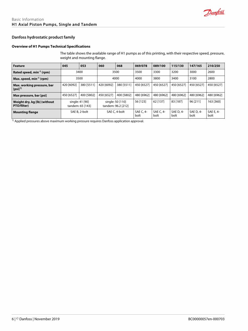
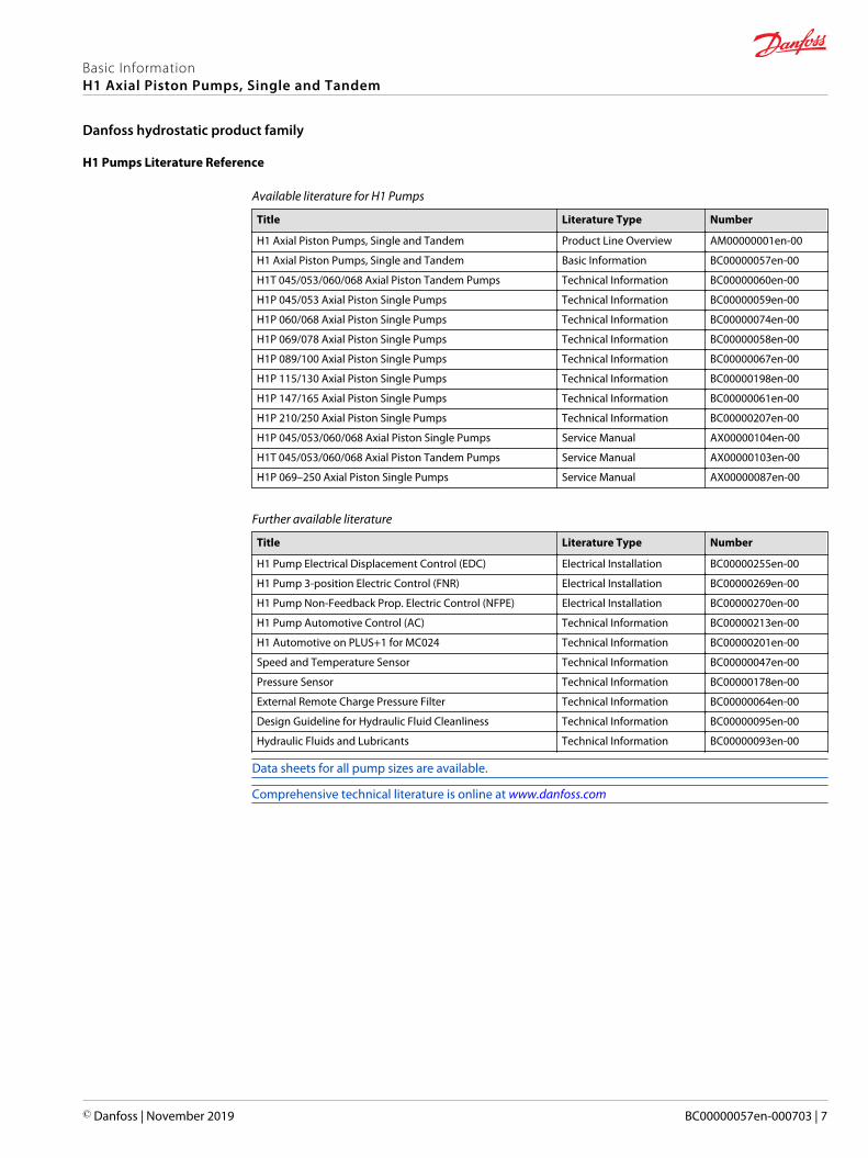
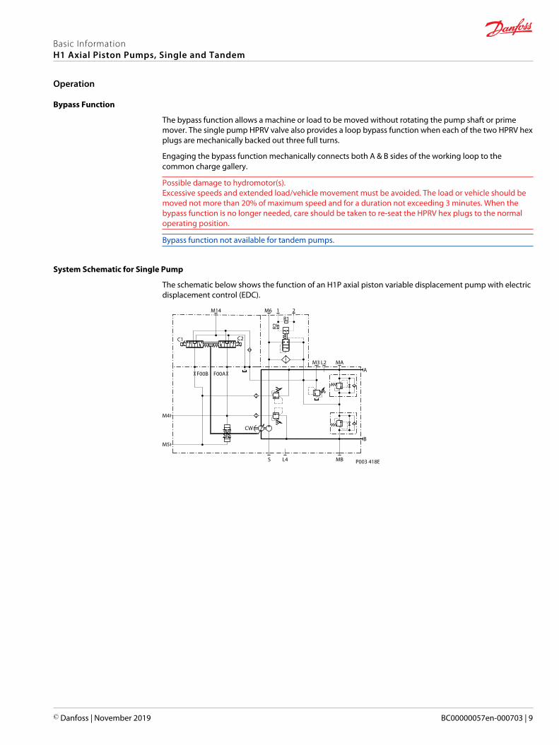
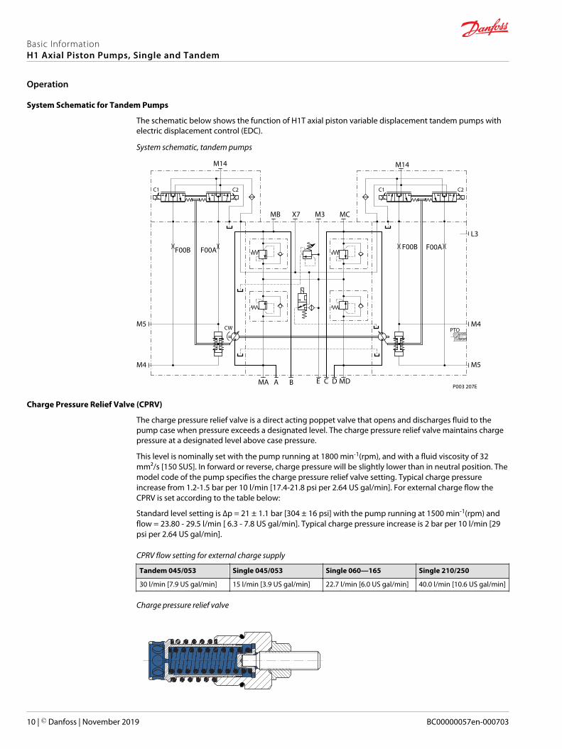
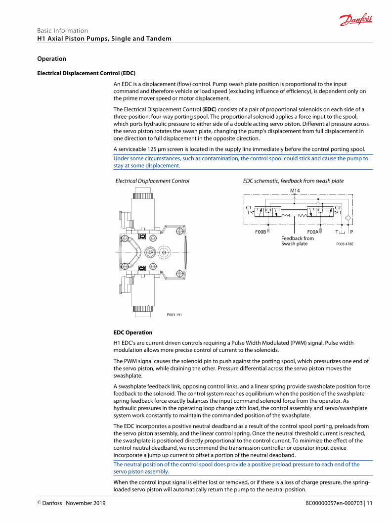
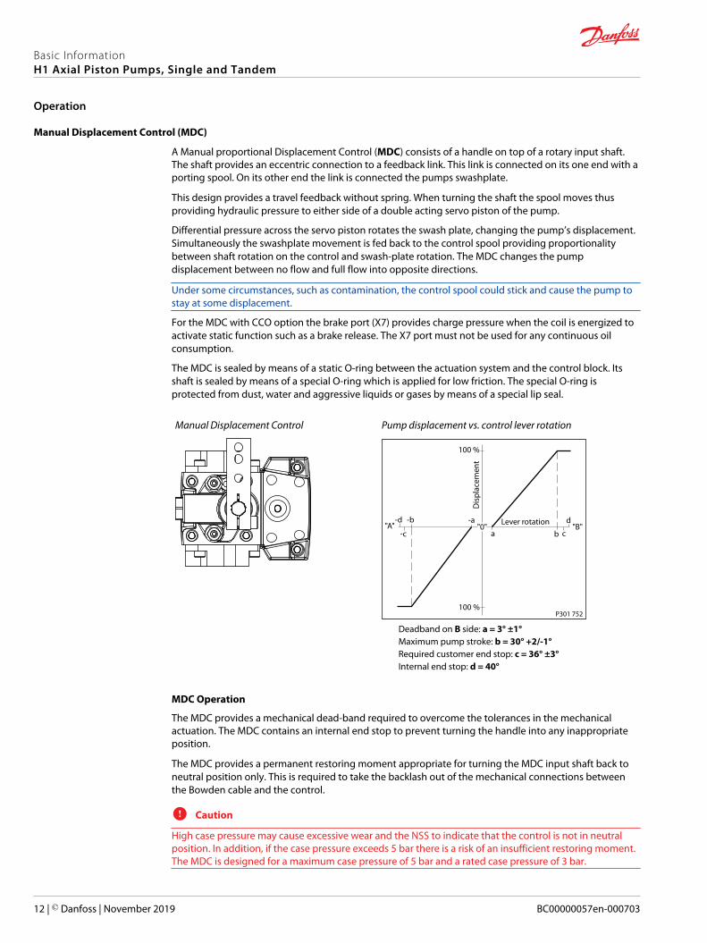
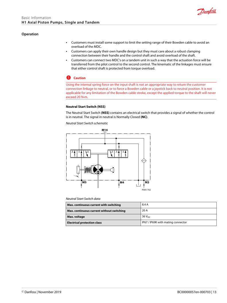
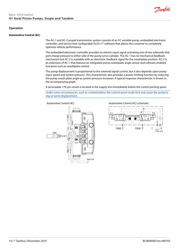
Automotive Control (AC)
The AC-1 and AC-2 propel transmission system consists of an H1 variable pump embedded electroniccontroller and service tool configurable PLUS+1reg software that allows the customer to completelyoptimize vehicle performance
The embedded electronic controller provides an electric input signal activating one of two solenoids thatport charge pressure to either side of the pump servo cylinder The AC-1 has no mechanical feedbackmechanism but AC-2 is available with an electronic feedback signal for the swashplate position AC-2 isan extension of AC-1 that features an integrated pump swashplate angle sensor and software enabledfunctions such as swashplate control
The pump displacement is proportional to the solenoid signal current but it also depends upon pumpinput speed and system pressure This characteristic also provides a power limiting function by reducingthe pump swash plate angle as system pressure increases A typical response characteristic is shown inthe accompanying graph
A serviceable 170 μm screen is located in the supply line immediately before the control porting spool
Under some circumstances such as contamination the control spool could stick and cause the pump tostay at some displacement
Automotive Control (AC)
P003 544
CAN
PPCPSC
PPUCC2
CC1
WA
RRAN
TY VOID
IF REMO
VED
CC3
Automotive Control (AC) schematic
P301 236
C2C1
F00A T PF00B
Basic InformationH1 Axial Piston Pumps Single and Tandem
Operation
14 | copy Danfoss | November 2019 BC00000057en-000703
Automotive Control connection diagram
Batt1224V DC
+ -
S 11
F 1
2
TerminalsBatt (+)
TerminalsBatt (-)
123456
DEUTSCH connectorDTM6 pin
Sensor A (+)Analog Input ASensor A (-)Sensor B (-)
PPC
Analog Input BSensor B (+)
123
DEUTSCH connectorDTM3 pin
CAN HighCAN LowCAN Shield
CAN
123456
DEUTSCH connectorDTM6 pin
PWM C1 (+)PWM C2 (+)Digital Output A1 (+)Digital Output A2 (-)
PSC
PWM C2 (-)PWM C1 (-)
123
DEUTSCH connectorDTM3 pin
Sensor (+)Pump RPM Input (Frequency)Sensor (-)
PPU
TerminalsSensor (-)
TerminalsSensor (+)
CC1p01
CC1p02
CC1p03
CC1p04Motor RPMDirection
CC1p05
123456789
101112
DEUTSCH connector DTM12 pin
Inch Input (Analog-Red)Mode Switch B Input (Digital-Nom)Motor PROPPCOR Output (PWM)Motor Direction Input (Analog)Sensor (+)Sensor (-)Inch Input (Analog-Nom)Motor BPD Output (Digital)Digital Output B2 (-)Digital Output B1 (+)Mode Switch A Input (Digital)Mode Switch B Input (Digital-Red)
CC2
123456789
101112
DEUTSCH connectorDTM12 pin
Battery (-) Battery (+)Sensor (+) Sensor (-)Motor RPM Input (Frequency)Forward Input (Digital)Reverse Input (Digital)Sensor (+) Sensor (-)Drive Pedal Input (Analog-Nom)Drive Pedal Input (Analog-Red)Neutral Input (Digital)
CC1
CC2p04
CC1p06
CC1p07
CC1p12
egHand BrakeSeat-Switch
FNR SwitchCC1p08
CC1p09
Rv
Rv
DriveCreepJoystickRocker Pedal
CC1p10
CAN BusCANp01
CANp02
CANp03
PSCp01
PSCp06PSCp03
PSCp04PSCp02
PSCp05
C 1
C 2
Electronic Displacement Control Pump
Pump RPMPPUp02
PPUp03
PPUp01
Mode Switch BCC2p02
2-P
BPD
PROP
CC2p03
CC2p03
CC2p08
CC2p05
CC2p06
Electronic Displacement Control Motor
Rv
Rv
Inch PedalCC2p07
Alternative Brake Pressure Inch Sensor
Reverse Motion
ParkingBrake
CC2p11
CC2p10
CC2p09
CC1p03
CC1p04
CC1p08
CC1p09
PPUp01
PPUp03
CC2p05
CC2p06
CC2p01
CC2p12
CNT
B
A
CC1p11
Mode Switch A
FNR in Reverse
BrakeLight
FaultLED
Vehicle-Speed-DependentOutput-Signal
ReverseLED
BrakeLight
FNR in Reverse
FaultLED
ForwardLED
BrakeLight
3
Nominal
Redundant
3
Reverse Motion
FNR in Reverse
1
2
DEUTSCH connectorDT2 pin
CC3
CC3p01
CC3p02
3
2
1 Contact capability min 10A
Melting fuse 16A
Functional optionsP003 536E
Basic InformationH1 Axial Piston Pumps Single and Tandem
Operation
copy Danfoss | November 2019 BC00000057en-000703 | 15
Forward-Neutral-Reverse (FNR) electric control
The 3-Position (F-N-R) control uses an electric input signal to switch the pump to a full stroke position
A serviceable 125 μm screen is located in the supply line immediately before the control porting spool
Under some circumstances such as contamination the control spool could stick and cause the pump tostay at some displacement
FNR control
P003 193
3-Position electric control hydraulic schematic
P003 189
C2C1
F00A
M14
T PF00B
Non Feedback Proportional Electric Control (NFPE)
The Non Feedback Proportional Electric (NFPE) control is an electrical automotive control in which anelectrical input signal activates one of two proportional solenoids that port charge pressure to either sideof the pump servo cylinder The NFPE control has no mechanical feedback mechanism
A serviceable 170 μm screen is located in the supply line immediately before the control porting spool
Under some circumstances such as contamination the control spool could stick and cause the pump tostay at some displacement
Non Feedback Proportional Electric Control
P003 192
NFPE schematic
P003 188
C2C1
F00A
M14
T PF00B
The pump displacement is proportional to the solenoid signal current but it also depends upon pumpinput speed and system pressure This characteristic also provides a power limiting function by reducing
Basic InformationH1 Axial Piston Pumps Single and Tandem
Operation
16 | copy Danfoss | November 2019 BC00000057en-000703
the pump swashplate angle as system pressure increases A typical response characteristic is shown inthe accompanying graph Under some circumstances such as contamination the control spool couldstick and cause the pump to stay at some displacement
NFPE pump displacement to Input signal
0
Signal Current mA(DC)
a b c
abc
Dis
plac
emen
t
100
100
NFPE control
∆p =
300
bar
∆p =
300
bar
∆p =
0 b
ar
∆p =
0 b
ar
P003 187E
Basic InformationH1 Axial Piston Pumps Single and Tandem
Operation
copy Danfoss | November 2019 BC00000057en-000703 | 17
Fan Drive Control (FDC)
The Fan Drive Control (FDC) is a non-feedback control in which an electrical input signal activates theproportional solenoid that ports charge pressure to either side of the pump servo cylinder The singleproportional solenoid is used to control pump displacement in the forward or reverse direction
The control spool is spring biased to produce maximum forward pump displacement in the absence ofan electrical input signal Based on the spring bias spool default forward flow for a CW rotation pump isout of port B while default forward flow for a CCW rotation pump is out of port A
Under some circumstances such as contamination the control spool could stick and cause the pump tostay at some displacement
FDC control
P301 441
FDC schematic
PTF00B
M14
C1 C2
F00A P301 442
The pump should be configured with 08 mm control orifices to provide slowest response and maximizesystem stability Additionally pressure limiter (PL) valves are used to limit maximum fan trim speed inboth (forward and reverse) directions
H1 pumps with FDC will be delivered from factory with nominal pressure limiter setting of 150 bar [2175psi] The PL must be re-adjusted to ensure that the fan reaches the desired fan speed to satisfy thecooling needs of the system HPRV setting must be always at least 30 bar [435 psi] higher than PL setting
For more information necessary to properly size and configure a hydraulic fan drive system see HydraulicFan Drive Design Guidelines AB00000019
W Warning
Use in other systems could result in unintended movement of the machine or itrsquos elements Loss of theinput signal to this control will cause the pump to produce maximum flowThe FDC is for Fan Drive systems only
Due to the fail-safe functionality of the FDC control the pump will stroke to max displacement in case theinput signal to the pump control and the Diesel engine will be switched off at the same time In thissituation a low loop event can occur which may damage the pump Therefore itrsquos strictly recommendedto keep the input signal to the pump control alive while switching off the engineFor further information please contact your Danfoss representative
Control Signal Requirements FDC
The pump displacement is proportional to the solenoid signal current but it also depends upon pumpinput speed and system pressure This characteristic also provides a power limiting function by reducing
Basic InformationH1 Axial Piston Pumps Single and Tandem
Operation
18 | copy Danfoss | November 2019 BC00000057en-000703
the pump swash plate angle as system pressure increases A typical response characteristic is shown inthe accompanying graph below
100
100
Dis
plac
emen
t
0 Signal current (mA(DC Avg))
Max current
Na
b
∆p = 0 bar
∆p = 0 bar
∆p = 300 bar
Reverse
Forward
a ndash Forward thresholdb ndash Reverse thresholdN ndash Neutral override current
Control current requirements
Voltage a N b Pin config
12 VDC 780 mA 1100 mA 1300 mAany order
24 VDC 400 mA 550 mA 680 mA Factory test current for fan movement expect higher or lower value
Basic InformationH1 Axial Piston Pumps Single and Tandem
Operation
copy Danfoss | November 2019 BC00000057en-000703 | 19
Manual Override (MOR)
All controls are available with a manual override functionality either as a standard or as an option fortemporary actuation of the control to aid in diagnostics
Control with manual override
P003 204
MOR schematic (EDC control shown)
PTF00B
M14
C2C1
F00A
Feedback from swash plate
The MOR plunger has a 4 mm diameter and must be manually depressed to be engaged Depressing theplunger mechanically moves the control spool which allows the pump to go on stroke The MOR shouldbe engaged anticipating a full stroke response from the pumpAn o-ring seal is used to seal the MOR plunger where initial actuation of the function will require a forceof 45 N to engage the plunger Additional actuation typically require less force to engage the MORplungerProportional control of the pump using the MOR should not be expected
W Warning
Unintended MOR operation will cause the pump to go into stroke example vehicle lifted off the groundThe vehicle or device must always be in a safe condition when using the MOR function
Refer to control flow table for the relationship of solenoid to direction of flow
Basic InformationH1 Axial Piston Pumps Single and Tandem
Operation
20 | copy Danfoss | November 2019 BC00000057en-000703
Swashplate Angle Sensor for EDC Controls
The angle sensor detects the swash plate position with an accuracy dependent upon the calibrationeffort done for the application and direction of rotation from the neutral position At minimum the sensorcan be used for forward neutral and reverse (FNR) detection
The sensor works on the hall-effect technology The implemented technology is based on ameasurement of the magnetic field direction in parallel to the chip surface This field direction isconverted to a voltage signal at the output
Enhanced calibration of the non-linear behavior leads to more exact calculation of the pump swashplateangle The 4-pin DEUTSCH connector is part of the sensor housing The swashplate angle sensor isavailable for all EDC controls for 12 V and 24 V
Swashplate angle vs output of supply voltage
-18deg -13deg -8deg
100
90
80
70
60
50
40
30
20
10
0
Swashplate angle
Sens
or o
utpu
t
of s
uppl
y vo
ltage
-3deg 0deg 2deg 7deg 12deg 17deg
W Warning
Strong magnetic fields in the proximity of the sensor can influence the sensor signal and must beavoided
Contact your Danfoss representative in case the angle sensor will be used for safety functions
Basic InformationH1 Axial Piston Pumps Single and Tandem
Operation
copy Danfoss | November 2019 BC00000057en-000703 | 21
Swash Plate Angle Sensor for NFPE and AC2 Controls
The angle sensor detects the swash plate angle position and direction of rotation from the zero positionThe swash angle sensor works on the AMR sensing technology Under the saturated magnetic field theresistance of the element varies with the magnetic field direction
The output signal give a linear output voltage for the various magnet positions in the sensing range
P301 750
Swash plate angle vs output voltage
-25deg -20deg -15deg -10deg -5deg 0deg 5deg 10deg 15deg 20deg 25deg
5
45
4
35
3
25
2
15
1
05
0
Swashplate angle
Out
put v
olta
ge
(V
)
12
Basic InformationH1 Axial Piston Pumps Single and Tandem
Operation
22 | copy Danfoss | November 2019 BC00000057en-000703
Control Cut Off Valve (CCO)
The H1 pump offers an optional control cut off valve integrated into the control All EDC NFPE and MDCcontrols are available with a CCO valve This valve will block charge pressure to the control allowing theservo springs to de-stroke both pumps regardless of the pumpacutes primary control input
There is also a hydraulic logic port X7 which can be used to control other machine functions such asspring applied pressure release brakes The pressure at X7 is controlled by the control cut off solenoidThe X7 port would remain plugged if not needed
In the normal (de-energized) state of the solenoid charge flow is prevented from reaching the controls Atthe same time the control passages and the X7 logic port are connected and drained to the pump caseThe pump will remain in neutral or return to neutral independent of the control input signal Return toneutral time will be dependent on oil viscosity pump speed swashplate angle and system pressure
When the solenoid is energized charge flow and pressure is allowed to reach the pump control The X7logic port will also be connected to charge pressure and flow
The solenoid control is intended to be independent of the primary pump control making the control cutoff an override control feature It is however recommended that the control logic of the CCO valve bemaintained such that the primary pump control signal is also disabled whenever the CCO valve is de-energized Other control logic conditions may also be considered
The CCO valve is available with 12 V or 24 V solenoid
The response time of the unit depends on the control type and the used control orifices
CCO schematic (MDC shown)
P005 703
M14 X7
Brake gauge port with MDC
C Caution
It is not recommended to use brake port for any external flow consumption to avoid malfunction of CCOfunction
Basic InformationH1 Axial Piston Pumps Single and Tandem
Operation
copy Danfoss | November 2019 BC00000057en-000703 | 23
Displacement Limiter
H1 pumps are designed with optional mechanical displacement (stroke) limiters factory set to maxdisplacement The maximum displacement of the pump can be set independently for forward andreverse using the two adjustment screws to mechanically limit the travel of the servo piston down to 50displacement
Adjustments under operating conditions may cause leakage The adjustment screw can be completelyremoved from the threaded bore if backed out to far
P003 266
Life Time
Hydraulic unit life depends on the speed and normal operating or weighted average pressure that canonly be determined from a duty cycle analysis
The life of the product depends on several factors such as speed pressure swash plate angle to name afew
For detailed product life calculation please contact your Danfoss representative
Basic InformationH1 Axial Piston Pumps Single and Tandem
Operation
24 | copy Danfoss | November 2019 BC00000057en-000703
Speed and Temperature Sensor
Description
Function of the speed sensor is to detect the shaft speed Typically the sensor is mounted to the housingof a Danfoss pump or motor and senses the speed from a target ring that is rotating inside the pump ormotor
Because of the digital output signals for speed the sensor is ideal for high and low speed measurements
The speed sensor is designed for rugged outdoor mobile or heavy industrial speed sensing applications
The detection of the speed is contactless It is custom-designed for Danfoss It is a Plug and Perform devicethat does not need any calibration or adjustments
For diagnostics and other purposes some sensor also has the capability to detect the driving directionand the case oil temperature
Theory of Operation
The speed sensor is externally powered and in response to the speed of the target ring outputs a digitalpulse signal A magnet inside the sensor provides the magnetic field that changes with the position ofthe target teeth
The target ring is attached to the cylinder block or the shaft Hall sensors change from highlow state asthe target teeth pass by the sensoracutes face The digital (on-off-on-off ) pulse train is fed to a controllerwhich interprets its rate of change as a speed
Some speed sensor uses two Hall sensors with specific distance and orientation resulting in a pulse trainoutput shift of 90deg between the two sensors A logic circuit decodes the two signals to provide anadditional direction indication (high or low depending on direction)
Due to the design of the sensor the duty cycle (ratio between on and off time at constant speed) of bothspeed signals at any working condition is close to 50 and can be used for better resolution at lowspeeds
Target Ring
Speed (target) rings vary according to the diameter of the cylinder block or shaft on which they areinstalled The number of teeth is shown in the table below
The number of speed (target) ring teeth
H1P size 045053 060068 069078 089100 115130 147165 210250
Teeth 79 86 86 92 102 108 90
Mating Connectors
Mating connectors ordering data
Ordering data
Description Quantity Ordering number
Mating connector 1 DEUTSCH DT06-6S
Wedge lock 1 DEUTSCH WM65
Socket contact (16 and 18 AWG) 6 DEUTSCH 0462-201-2031
DEUTSCH mating connector kit 1 11033865
Basic InformationH1 Axial Piston Pumps Single and Tandem
Operation
copy Danfoss | November 2019 BC00000057en-000703 | 25
Speed Sensor 45 ndash 8 V Technical Data
Speed sensor connector 6-pin
4
3 2 1
5 6
P006035
1 Speed signal 22 Direction signal3 Speed signal 14 Supply5 Ground6 Temperature
Technical data
Parameter Min Nom Max Note
Supply voltage 45 VDC 5 VDC 8 VDC Regulated supply voltageReverse polarity protected
Supply protection ndash ndash 30 VDC Shuts off above 9 V
Max required supply current ndash ndash 25 mA At supply voltage
Max output current ndash ndash 50 mA
Operation mode NPN amp PNP Push-Pull amplifier
Temperature signal -40degC = 2318V ndash 100degC = 0675V
Output low speed signal 5 85 12 Ratiometric output voltageLow state gt 0 V to provide wirefault detection
Output high speed signal 88 915 95
Detectable frequency range 1 Hz ndash 10 000 Hz
Ordering number 149055
Color of connector Black
Temperature Sensor Data
For calculation of the case fluid temperature and the output signal voltage see the formulas below
VO ndash Measured output voltage (V)
Vo= (-388 bull 10-6 bull T2) + (-115 bull 10-2 bull T) + 18639
T ndash Temperature (degC)
T = ndash148196 + radic 21962 106 + (18639 ndash Vordm)388 10-6
Output signal voltage vs Temperature
Temperature range
-55 degC -40 degC -30 degC 0 degC +30 degC +80 degC +100 degC +130 degC
2485 V 2318 V 2205 V 1864 V 1515 V 0919 V 0675 V 0303 V Accuracy plusmn1 5 to plusmn 4 degC Accuracy plusmn25 to plusmn 5 degC
Basic InformationH1 Axial Piston Pumps Single and Tandem
Operation
26 | copy Danfoss | November 2019 BC00000057en-000703
Response time in fluid
T90 definition
00
10
20
30
40
50
60
70
80
90
-100 100 200 300 400 500 600 700 800 900 1000P003531E
Real temperatureTemperatureSignal
T90 definition
T90
Time (S)
Tem
pera
ture
(degC)
90
of ∆
Tem
p
∆ T
emp
Response time in fluid (T90) = 360 s
Basic InformationH1 Axial Piston Pumps Single and Tandem
Operation
copy Danfoss | November 2019 BC00000057en-000703 | 27
Input Speed
Minimumspeed
is the lowest input speed recommended during engine idle condition Operating belowminimum speed limits the pumprsquos ability to maintain adequate flow for lubrication andpower transmission
Rated speed is the highest input speed recommended at full power condition Operating at orbelow this speed should yield satisfactory product life
Operating conditions between rated and maximum speed should be restricted to lessthan full power and to limited periods of time
Maximumspeed
is the highest operating speed permitted Exceeding maximum speed reduces productlife and can cause loss of hydrostatic power and braking capacity For most drivesystems maximum unit speed occurs during downhill braking or negative powerconditions
W Warning
Never exceed the maximum speed limit under any operating conditions
During hydraulic braking and downhill conditions the prime mover must be capable of providingsufficient braking torque in order to avoid pump over speed This is especially important to consider forturbo-charged and Tier 4 engines
For more information please see Pressure and Speed Limits BLN-9884 when determining speed limits fora particular application
System Pressure
Hydraulic unit life depends on the speed and normal operating mdash or weighted average mdash pressure thatcan only be determined from a duty cycle analysis
System pressure is the differential pressure between high pressure system ports It is the dominantoperating variable affecting hydraulic unit life High system pressure which resultsfrom high load reduces expected life
Applicationpressure
is the high pressure relief or pressure limiter setting normally defined within theorder code of the pump This is the applied system pressure at which the drive linegenerates the maximum calculated pull or torque in the application
Maximumworkingpressure
is the highest recommended application pressure and is not intended to be acontinuous pressure Propel systems with application pressures at or below thispressure should yield satisfactory unit life given proper component sizingApplication pressures above maximum working pressure will only be consideredwith duty cycle analysis and factory approval
Pressure spikes are normal and must be considered when reviewing maximumworking pressure
Maximumpressure
is the highest intermittent pressure allowed under any circumstances Applicationswith applied pressures between rated and maximum require factory approval withcomplete application duty cycle and life expectancy analysis
Minimum lowloop pressure
must be maintained under all operating conditions to avoid cavitation
All pressure limits are differential pressures referenced to low loop (charge) pressureSubtract low loop pressure from gauge readings to compute the differential
Basic InformationH1 Axial Piston Pumps Single and Tandem
Operating Parameters
28 | copy Danfoss | November 2019 BC00000057en-000703
Servo Pressure
Servo pressure is the pressure in the servo system needed to position and hold the pump on stroke Itdepends on system pressure and speed At minimum servo pressure the pump will run at reduced strokedepending on speed and pressure
Minimum servo pressure at corner power holds the pump on full stroke at max speed and maxpressure
Maximum servo pressure is the highest pressure typically given by the charge pressure setting
Charge Pressure
An internal charge relief valve regulates charge pressure Charge pressure supplies the control withpressure to operate the swashplate and to maintain a minimum pressure in the low side of thetransmission loop
The charge pressure setting listed in the order code is the set pressure of the charge relief valve with thepump in neutral operating at 1800 min-1 (rpm) and with a fluid viscosity of 32 mm2s [150 SUS]
Pumps configured with no charge pump (external charge supply) are set with a charge flow of 30 lmin[793 US galmin] and a fluid viscosity of 32 mm2s [150 SUS]
The charge pressure setting is referenced to case pressure Charge pressure is the differential pressureabove case pressure
Minimumchargepressure
is the lowest pressure allowed to maintain a safe working condition in the low side ofthe loop Minimum control pressure requirements are a function of speed pressureand swashplate angle and may be higher than the minimum charge pressure shownin the Operating parameters tables
Maximumchargepressure
is the highest charge pressure allowed by the charge relief adjustment and whichprovides normal component life Elevated charge pressure can be used as asecondary means to reduce the swashplate response time
Charge Pump Inlet Pressure
At normal operating temperature charge inlet pressure must not fall below rated charge inlet pressure(vacuum)
Minimum charge inletpressure
is only allowed at cold start conditions In some applications it isrecommended to warm up the fluid (eg in the tank) before starting theengine and then run the engine at limited speed
Maximum charge inletpressure
may be applied continuously
Case Pressure
Under normal operating conditions the rated case pressure must not be exceeded During cold start casepressure must be kept below maximum intermittent case pressure Size drain plumbing accordingly
The auxiliary pad cavity of axial pumps configured without integral charge pumps is referenced to casepressure Units with integral charge pumps have auxiliary mounting pad cavities referenced to chargeinlet (vacuum)
Possible component damage or leakageOperation with case pressure in excess of stated limits may damage seals gaskets andor housingscausing external leakage Performance may also be affected since charge and system pressure areadditive to case pressure
Basic InformationH1 Axial Piston Pumps Single and Tandem
Operating Parameters
copy Danfoss | November 2019 BC00000057en-000703 | 29
External Shaft Seal Pressure
In certain applications the input shaft seal may be exposed to external pressure In order to preventdamage to the shaft seal the maximum differential pressure from external sources must not exceed 04bar (58 psi) over pump case pressure
The case pressure limits of the pump must also be followed to ensure the shaft seal is not damaged
C Caution
Regardless of the differential pressure across the shaft seal the shaft seal has been known to pump oilfrom the external source (e g gear box) into the pump case
Temperature
The high temperature limits apply at the hottest point in the transmission which is normally the motorcase drain The system should generally be run at or below the quoted rated temperature
The maximum intermittent temperature is based on material properties and should never beexceeded
Cold oil will generally not affect the durability of the transmission components but it may affect theability of oil to flow and transmit power therefore temperatures should remain 16 degC [30 degF] above thepour point of the hydraulic fluid
The minimum temperature relates to the physical properties of component materials
Size heat exchangers to keep the fluid within these limits Danfoss recommends testing to verify thatthese temperature limits are not exceeded
Viscosity
For maximum efficiency and bearing life ensure the fluid viscosity remains in the recommended range
The minimum viscosity should be encountered only during brief occasions of maximum ambienttemperature and severe duty cycle operation
The maximum viscosity should be encountered only at cold start
Basic InformationH1 Axial Piston Pumps Single and Tandem
Operating Parameters
30 | copy Danfoss | November 2019 BC00000057en-000703
Fluid Specification
Viscosity
Intermittent1) 5 mm2s [42 SUS]
Minimum 7 mm2s [49 SUS]
Recommended range 12 ndash 80 mm2s [66 ndash 370 SUS]
Maximum 1600 mm2s [7500 SUS]
1) Intermittent = Short term t lt 1 min per incident and not exceeding 2 of duty cycle based load-life
Temperature
Minimum 1) -40degC [-40degF]
Rated 104degC [220degF]
Recommended range2) 60 ndash 85degC [140 ndash 185degF]
Maximum Intermittent 115degC [240degF]
1) Cold start = Short term t gt 3 min p le 50 bar [725 psi] n le 1000 min-1 (rpm)2) At the hottest point normally case drain port
Fluid selection
Ratings and performance data are based on operating with hydraulic fluids containing oxidation rustand foam inhibitors These fluids must possess good thermal and hydrolytic stability to prevent wearerosion and corrosion of pump components
C Caution
Never mix hydraulic fluids of different types
Basic InformationH1 Axial Piston Pumps Single and Tandem
System design parameters
copy Danfoss | November 2019 BC00000057en-000703 | 31
Filtration System
To prevent premature wear ensure only clean fluid enters the hydrostatic transmission circuit A filtercapable of controlling the fluid cleanliness to ISO 4406 class 221813 (SAE J1165) or better under normaloperating conditions is recommended
These cleanliness levels can not be applied for hydraulic fluid residing in the component housingcase orany other cavity after transport
The filter may be located on the pump (integral) or in another location (remote) The integral filter has afilter bypass sensor to signal the machine operator when the filter requires changing Filtration strategiesinclude suction or pressure filtration
The selection of a filter depends on a number of factors including the contaminant ingression rate thegeneration of contaminants in the system the required fluid cleanliness and the desired maintenanceinterval Filters are selected to meet the above requirements using rating parameters of efficiency andcapacity
Filter efficiency can be measured with a Beta ratio (βX) For simple suction filtered closed circuittransmissions and open circuit transmissions with return line filtration a filter with a β-ratio within therange of β35-45 = 75 (β10 ge 2) or better has been found to be satisfactory
For some open circuit systems and closed circuits with cylinders being supplied from the same reservoira considerably higher filter efficiency is recommended This also applies to systems with gears or clutchesusing a common reservoir
For these systems a charge pressure or return filtration system with a filter β-ratio in the range of β15-20 =75 (β10 ge 10) or better is typically required
Because each system is unique only a thorough testing and evaluation program can fully validate thefiltration system
Please see Design Guidelines for Hydraulic Fluid Cleanliness Technical Information BC00000095 for moreinformation
Filter βx-ratio is a measure of filter efficiency defined by ISO 4572 It is defined as the ratio of the numberof particles greater than a given diameter (ldquoxrdquo in microns) upstream of the filter to the number of theseparticles downstream of the filter
Filtration cleanliness level and βx-ratio (recommended minimum)
Cleanliness per ISO 4406 221813
Efficiency βx (charge pressure filtration) β15-20 = 75 (β10 ge 10)
Efficiency βx (suction and return line filtration) β35-45 = 75 (β10 ge 2)
Recommended inlet screen mesh size 100 ndash 125 microm
Basic InformationH1 Axial Piston Pumps Single and Tandem
System design parameters
32 | copy Danfoss | November 2019 BC00000057en-000703
Suction Filtration
The suction filter is placed in the circuit between the reservoir and the inlet to the charge pump
Suction filtration
P003 471E
ReservoirStrainer
Filter
ChargepumpCharge
reliefvalveto pump case
to low pressureside of loopand servo control
Possible charge pump damage Clogged filters can cause cavitation which damages the charge pumpWe recommend a filter bypass with a filter bypass sensor to prevent damage due to blocked suctionfilters
Charge pressure filtration (full charge pump flow)
Charge pressure filtration can mitigate high inlet vacuum in cold start-ups and provides fluid filtrationimmediately prior to entrance to the loop and the control system Pressure filtration provides a higherlevel of filtering efficiency than suction filtration
For most H1 pumps exist two types of pressure filtrationbull remote pressure filtration (filter remotely mounted on vehicle)bull integral pressure filtration (filter mounted to the endcap)
Remote charge pressure filtration full flow
Reservoir
Charge pump
Charge relief valve
to pump case
to low pressure side of loop and servocontrol
Strainer
P003 472E
Filter with bypass
Bypass
Filter bypass sensor
Basic InformationH1 Axial Piston Pumps Single and Tandem
System design parameters
copy Danfoss | November 2019 BC00000057en-000703 | 33
Integral charge pressure filtration full flow
Reservoir
Charge pump
Charge relief valve
to pump case
to low pressure side of loop and servocontrol
Strainer
P003 473E
Filter with bypass
Bypass
Filter bypass sensor
Verify option availability in the size specific technical information In either case the filtration circuit is thesame with the filter element situated in the circuit downstream the charge pump and upstream of thecharge relief valve such that full charge flow is continuously filtered
Filters used in charge pressure filtration circuits must be rated to at least 35 bar [508 psi] pressure A 100 ndash125 microm screen located in the reservoir or in the charge inlet line is recommended when using chargepressure filtration
A filter bypass valve is necessary to prevent filter damage and to avoid contaminants from being forcedthrough the filter media by high pressure differentials across the filter
In the event of high pressure drop associated with a blocked filter or cold start-up conditions fluid willbypass the filter Working with an open bypass should be avoided
Remote Charge Pressure Filtration
Ports at the endcap are available to allow for the charge filter to be located conveniently for easy serviceand replacement
Possible charge pump damage Remote filter heads without bypass and poor plumbing design canencounter excessive pressure drops that can lead to charge pump damage in addition to contaminantsbeing forced through the filter media and into the transmission loopCare should be taken to minimize the hydraulic pressure drops associated with long connecting linessmall diameter hoses or restrictive port adaptors at the filter head or endcap Ensure the normaloperating pressure drop across the remote filtration in and out ports is sufficiently below the crackpressure setting of the recommended filter bypass valve
Basic InformationH1 Axial Piston Pumps Single and Tandem
System design parameters
34 | copy Danfoss | November 2019 BC00000057en-000703
Integral Charge Pressure Filtration
The H1 integral pressure filter head is designed with a filter bypass valve and non-contacting bypasssensor The pressure differential acting on the filter element also acts on a spring biased bypass spool
This spool is designed with a magnetic area When a certain spool position is reached the magnet closesa switch in the bypass sensor which allows R2 to be in parallel with R1 This occurs without anymechanical contact between the spool and the bypass sensor
The position of the bypass spool is indicated by the change in the measured sensor resistance Thechange in resistance occurs when R2 is switched in and out of the circuit
When the filter is not being bypassed the nominal measured resistance is 510 Ω When the switch isclosed the nominal measured resistance is 122 Ω
The bypass spool is designed so the bypass sensor switch will be closed before oil bypasses the filterelement This gives the machine operator an indication that the filter is very close to bypassing and afilter replacement is required
For cold start conditions it is typical that the filter may bypass for a short amount of time while the oil iswarming up At normal operating oil temperatures a system that does not yet need a filter replacementwill operate in the non-bypass mode The addition of an oil temperature sensor and additional controllogic is recommended to properly determine if a filter replacement is required
Integral filter head with filter bypass sensor
Bypass spool
Filterbypass sensor
Filterelement
P003 359E
Pressure data
Filter bypass sensor switch closure ∆p Bypass valve ∆p above sensor setting
45 plusmn08 bar [6227 plusmn116 psi] 12 plusmn02 bar [174 plusmn29 psi]
Electric data
Max voltage 48 V
Max power 06 W
Switch open closed 510 122 Ω
Resistor tolerance 1
Temperature range -20 divide +100 degC [-4 divide +212 degF]
IP Rating (IEC 60 529) + DIN 40 050 IP 69K part 9 with mating connector
Nominal flow at 30 mmsup2s and Δp 05 bar [73 psi]
Short 60 lminMin β75 (c) = 75 (β5 (c) ge 10) according to ISO 16889(clean filter element only)Medium 80 lmin
Long 105 lmin
Basic InformationH1 Axial Piston Pumps Single and Tandem
System design parameters
copy Danfoss | November 2019 BC00000057en-000703 | 35
Schematic
P003 195
21M6
outin
R1
R2
Bypass sensor open
Bypass valveclosed
Connector
P003 198E
ConnectorDeutsch DTM04-2P
M6916 -18before filter (upstream)
Connector pin assignment (any order)
Connector Pin assignment Or Pin assignment
2 1 1 Supply2 Ground (GND)
Alternative 1 Ground (GND)2 Supply
H1 filter bypass sensor mating connector parts list
Description Quantity Order number
Mating connector 1 DEUTSCH DTM06-2S
Secondary wedge lock 1 DEUTSCH WM-2S
Socket terminal 2 DEUTSCH 0462-201-20141
Danfoss mating connector kit 1 11031205
H1P Filters Ordering Numbers
The H1 pumps with an integrated filter option are shipped with a filter of length as indicated below
H1 pump size Filter element length Ordering number
H1P 069078 089100 Medium 11004918
H1P 115130 147165 Long 11004919
Basic InformationH1 Axial Piston Pumps Single and Tandem
System design parameters
36 | copy Danfoss | November 2019 BC00000057en-000703
Filter Bypass Characteristic
The diagram below shows the differential pressure between filter in and out with a filter elementcompletely blocked so that all flow runs across the filter bypass valve
Filter bypass characteristic (completely blocked element)
0
20[528]
40[1057]
60[1585]
80[2113]
100[2642]
120[3170]
022
[319]20
[290]18
[261]16
[232]14
[203]12
[174]10
[145]8
[116]6
[87]4
[58]2
[29]
Flow
lm
in [U
S ga
lmin
]
Differential pressure over filter bypass bar [psi](blocked filter element) P003 185E
Filter bypasssensor activated
8 m
m2 s
[52
SUS]
74 m
m2 s
[342
SUS
]
1600 mm
2 s [7406 SUS]
Bypass Sensor Clearance
The bypass sensor is activated by the magnetic bypass valve
No steel parts are allowed within a radius of 150 mm [591 in] Moving steel devices or parts are notallowed within a radius of 250 mm [984 in]
P003 356E
mm[in]
38[150]
150 min[591]
250 min[984]
37[1
46]
Independant Braking System
Unintended vehicle or machine movement hazard Exceeding maximum speed may cause a loss ofhydrostatic drive line power and braking capacityMachine manufacturer is responsible to provide a braking system redundant to the hydrostatictransmission sufficient to stop and hold the vehicle or machine in the event of hydrostatic drive powerloss The braking system must also be sufficient to hold the machine in place when full power is applied
Basic InformationH1 Axial Piston Pumps Single and Tandem
System design parameters
copy Danfoss | November 2019 BC00000057en-000703 | 37
Reservoir
The hydrostatic system reservoir should accommodate maximum volume changes during all systemoperating modes and promote de-aeration of the fluid as it passes through the tank A suggestedminimum total reservoir volume is 5frasl8 of the maximum charge pump flow per minute with a minimumfluid volume equal to frac12 of the maximum charge pump flow per minute This allows 30 seconds fluiddwell for removing entrained air at the maximum return flow This is usually adequate to allow for aclosed reservoir (no breather) in most applications
Locate the reservoir outlet (charge pump inlet) above the bottom of the reservoir to take advantage ofgravity separation and prevent large foreign particles from entering the charge inlet line A 100-125 micromscreen over the outlet port is recommended Position the reservoir inlet (fluid return) to discharge belowthe normal fluid level toward the interior of the tank A baffle (or baffles) will further promote de-aerationand reduce surging of the fluid
Case drain
All single H1 pumps are equipped with multiple drain ports whereas some H1 pumps are equipped withtwo case drain port sizes Port selection and case drain routing must enable the pump housing tomaintain a volume of oil not less than half full and normal operating case pressure limits of the unit aremaintained Case drain routing and design must consider unit case pressure ratings
A case drain line must be connected to one of the case outlets to return internal leakage to the systemreservoir
Basic InformationH1 Axial Piston Pumps Single and Tandem
System design parameters
38 | copy Danfoss | November 2019 BC00000057en-000703
Charge pump
Charge flow is required on all H1 pumps applied in closed circuit installations The charge pump providesflow to make up internal leakage maintain a positive pressure in the main circuit provide flow forcooling and filtration replace any leakage losses from external valving or auxiliary systems and toprovide flow and pressure for the control system
Many factors influence the charge flow requirements and the resulting charge pump size selection Thesefactors include system pressure pump speed pump swashplate angle type of fluid temperature size ofheat exchanger length and size of hydraulic lines control response characteristics auxiliary flowrequirements hydrostatic motor type etc When initially sizing and selecting hydrostatic units for anapplication it is frequently not possible to have all the information necessary to accurately evaluate allaspects of charge pump size selection
Unusual application conditions may require a more detailed review of charge pump sizing Chargepressure must be maintained at a specified level under all operating conditions to prevent damage to thetransmission Danfoss recommends testing under actual operating conditions to verify this
Charge pump sizingselection
In most applications a general guideline is that the charge pump displacement should be at least 10 ofthe total displacement of all components in the system Unusual application conditions may require amore detailed review of charge flow requirements Please refer to Selection of Drive Line ComponentsBLN-9885 for a detailed procedure
System features and conditions which may invalidate the 10 guideline include (but are not limited to)bull Continuous operation at low input speeds (lt 1500 min-1 (rpm))bull High shock loading andor long loop linesbull High flushing flow requirementsbull Multiple Low Speed High Torque motorsbull High input shaft speeds
Basic InformationH1 Axial Piston Pumps Single and Tandem
System design parameters
copy Danfoss | November 2019 BC00000057en-000703 | 39
Bearing loads and life
Bearing life is a function of speed system pressure charge pressure and swashplate angle plus anyexternal side or thrust loads The influence of swashplate angle includes displacement as well asdirection External loads are found in applications where the pump is driven with a sidethrust load (beltor gear) as well as in installations with misalignment and improper concentricity between the pump anddrive coupling All external side loads will act to reduce the normal bearing life of a pump Other lifefactors include oil type and viscosity
In vehicle propel drives with no external shaft loads and where the system pressure and swashplateangle are changing direction and magnitude regularly the normal L20 bearing life (80 survival) willexceed the hydraulic load-life of the unit
In non propel drives such as vibratory drives conveyor drives or fan drives the operating speed andpressure are often nearly constant and the swashplate angle is predominantly at maximum These driveshave a distinctive duty cycle compared to a propulsion drive In these types of applications a bearing lifereview is recommended
Applications with external shaft loads H1 pumps are designed with bearings that can accept someexternal radial and thrust loads When external loads are present the allowable radial shaft loads are afunction of the load position relative to the mounting flange the load orientation relative to the internalloads and the operating pressures of the hydraulic unit In applications where external shaft loads cannotbe avoided the impact on bearing life can be minimized by proper orientation of the load Optimumpump orientation is a consideration of the net loading on the shaft from the external load the pumprotating group and the charge pump loadbull In applications where the pump is operated such that nearly equal amounts of forward vs reverse
swashplate operation is experienced bearing life can be optimized by orientating the external sideload at 0deg or 180deg such that the external side load acts 90deg to the rotating group load (for details seedrawing below)
bull In applications where the pump is operated such that the swashplate is predominantly (gt 75 ) onone side of neutral (eg vibratory conveyor typical propel) bearing life can be optimized byorientating the external side load generally opposite of the internal rotating group load The directionof internal loading is a function of rotation and system port which has flow out Tables are availablein the Controls section of each H1 size specific technical information that illustrates the flow out portas a function of pump rotation and energized EDC solenoid
bull H1 pumps are designed with bearings that can accept some thrust load such that incidental thrustloads are of no consequence When thrust loads are anticipated the allowable load will depend onmany factors and it is recommended that an application review be conducted
Contact Danfoss for a bearing life review if external side loads are present
Radial load position
P003 318E
L
270deg Re
Re
Me
180deg Re
90deg Re
0deg Re
Me = Shaft momentL = Flange distanceRe = External force to the shaft
Allowable shaft loads and moments are shown for each size specific technical information
Basic InformationH1 Axial Piston Pumps Single and Tandem
System design parameters
40 | copy Danfoss | November 2019 BC00000057en-000703
Mounting flange loads
Adding tandem mounted auxiliary pumps andor subjecting pumps to high shock loads may result inexcessive loading of the mounting flange Applications which experience extreme resonant vibrations orshock may require additional pump support The overhung load moment for multiple pump mountingmay be estimated using the formula below
Overhung load example
P005 275
L1L2
L3
F2 F1F3
Estimating overhung load moments max and rated acceleration factors for some typical applications
Rated load moment Shock load moment
MR = g bull GR (W1L1 + W2L2 + + WnLn) Nbullm [lbfbullin] MS = g bull GS (W1L1 + W2L2 + + WnLn) Nbullm [lbfbullin]
Variablesg = Gravity 981 mssup2GR = Calculation factor for rated (vibratory) acceleration This factor depends on the applicationGS = Calculation factor for max shock acceleration This factor depends on the applicationW = MassWeight of pump kg [lb]L = Distance from mounting flange to pump center of gravity m [in] (refer to Installation drawings)
Allowable overhung load moment values are given for each size specific technical information Exceedingthese values requires additional pump support
Typical G loads for various applications
Application Calculation factor
Rated (vibratory) acceleration GR Maximum (shock) acceleration GS
Skid Steer Loader 8 15-20
Trencher (rubber tires) 3 8
Asphalt Paver 2 6
Windrower 2 5
Aerial Lift Turf Care 15 4
Vibratory Roller 6 10
Use these in the absence of specific data for a rough estimation
Basic InformationH1 Axial Piston Pumps Single and Tandem
System design parameters
copy Danfoss | November 2019 BC00000057en-000703 | 41
Shaft Torque for Splined Shafts
The rated torque of a flooded spline can increase to that of the maximum published rating A floodedspline would be indicative of a pump driven by a pump drive or plugged into an auxiliary pad of a pump
Ratedtorque
is a measure of tooth wear and is the torque level at which a normal spline life of 2 x 10⁹
shaft revolutions can be expected The rated torque of a flooded spline can increase tothat of the maximum published rating A flooded spline would be indicative of a pumpdriven by a pump drive or plugged into an auxiliary pad of a pump
Presumes a regularly maintained minimum level of lubrication via a moly-disulfide greasein order to reduce the coefficient of friction and to restrict the presence of oxygen at thespline interface It is also assumed that the mating spline has a minimum hardness of Rc55 and full spline depth
The rated torque is proportional to the minimum active spline length
Maximumtorque
is based on torsional fatigue strength considering 100000 full load reversing cyclesHowever a spline running in oil-flooded environment provides superior oxygenrestriction in addition to contaminant flushing
Maintaining a spline engagement at least equal to the pitch diameter will also maximizespline life Spline engagements of less than frac34 pitch diameter are subject to high contactstress and spline fretting
Shaft Torque for Tapered Shafts
Rated torque is based on the contact pressure between the shaft and hub surfaces with poor surfacecontact areas With an increased quality of the contact areas the contact pressurebetween the shaft and hub is increased and allows higher torque to be transmitted
When a key is used for orientation of the hub on the shaft in conjunction with poorquality contact surfaces the transmitted torque will drop significantly This is due to thekey carrying the torque which limits the shaft torque carrying capability
Maximumtorque
is based on an ideal contact area of 100 and the retaining nut properly torqued Thisallows for the highest contact pressure between the shaft and the hub
Basic InformationH1 Axial Piston Pumps Single and Tandem
System design parameters
42 | copy Danfoss | November 2019 BC00000057en-000703
Shaft availability and torque ratings
Multiple pump installations must consider the loads from the entire pump stack and all torques areadditive Charge pumps loads must also be included
2 stage 1 stage
3 stage
P003 333E
Me1 for the second pumpMe3 for the next pump
Me1 for the first pumpMe input torque
C Caution
Ensure requirements do not exceed shaft torque ratings Torque required by auxiliary pumps is additive
Alignment between the mating splinersquos Pitch Diameters is another critical feature in determining theoperating life of a splined drive connection Plug-in or rigid spline drive installations can impose severeradial loads on the shafts
The radial load is a function of the transmitted torque and shaft eccentricity Increased spline clearancewill not totally alleviate this condition BUT increased spline clearance will prevent mechanicalinterference due to misalignment or radial eccentricity between the pitch diameters of the matingsplines Spline life can be maximized if an intermediate coupling is introduced between the bearingsupported splined shafts
Rated and maximum torque ratings for each available shaft is shown in the H1 size specific technicalinformation
Basic InformationH1 Axial Piston Pumps Single and Tandem
System design parameters
copy Danfoss | November 2019 BC00000057en-000703 | 43
Minimizing System Noise
Noise is transmitted in fluid power systems in two ways as fluid borne noise and structure borne noiseSystem lines and pump mounting can amplify pump noise
Fluid-bornenoise
(pressure ripple or pulsation) is created as pumping elements discharge oil into thepump outlet It is affected by the compressibility of the oil and the pumprsquos ability totransition pumping elements from high to low pressure Pulsations travel through thehydraulic lines at the speed of sound (about 1400 ms [4600 ftsec] in oil) until there is achange (such as an elbow) in the line Thus amplitude varies with overall line lengthand position
Structureborn noise
is transmitted wherever the pump casing connects to the rest of the system The waysystem components respond to excitation depends on their size form material andmounting
Follow the suggestions below to minimize noise in your applicationbull Use flexible hoses
bull Limit system line length
bull If possible optimize system line position to minimize noise
bull If you must use steel plumbing clamp the lines
bull If you add additional support use rubber mounts
bull Test for resonants in the operating range if possible avoid them
Basic InformationH1 Axial Piston Pumps Single and Tandem
System design parameters
44 | copy Danfoss | November 2019 BC00000057en-000703
Determination of Nominal Pump Sizes
Generally the sizing process is initiated by an evaluation of the machine system to perform the necessarywork function The following formulae can be used to determine the nominal pump size for a specificapplication
Metric System Inch System
Output flow Qe = 1000
Vg bull n bull ηv (lmin) Qe = 231
(US galmin)Vg bull n bull ηv
Input torque Me = 20 bull π bull ηm
Vg bull ∆p(Nbullm) Me =
2 bull π bull ηm
Vg bull ∆p(lbfbullin)
Input power Pe = 30 000 η
t
bull n bull p = 600 bullQe bull ∆pMe (kW) Pe =
198 000 ηt
bull n bull p = 1714 bullQe bull ∆pMe (hp)
VariablesVg = Displacement per revpHP = High pressurepNP = Low pressure∆p = pHP ndash pNPn = Input speedηv = Volumetric efficiencyηm = Mechanical (torque) efficiencyηt = Overall efficiency (ηv bull ηm)
SI units [US units]cm3rev [in3rev]bar [psi]bar [psi]bar [psi]min-1 (rpm)
Basic InformationH1 Axial Piston Pumps Single and Tandem
System design parameters
copy Danfoss | November 2019 BC00000057en-000703 | 45
Danfoss Power Solutions is a global manufacturer and supplier of high-quality hydraulic andelectric components We specialize in providing state-of-the-art technology and solutionsthat excel in the harsh operating conditions of the mobile off-highway market as well as themarine sector Building on our extensive applications expertise we work closely with you toensure exceptional performance for a broad range of applications We help you and othercustomers around the world speed up system development reduce costs and bring vehiclesand vessels to market faster
Danfoss Power Solutions ndash your strongest partner in mobile hydraulics and mobileelectrification
Go to wwwdanfosscom for further product information
We offer you expert worldwide support for ensuring the best possible solutions foroutstanding performance And with an extensive network of Global Service Partners we alsoprovide you with comprehensive global service for all of our components
Local address
Danfoss Power Solutions GmbH amp Co OHGKrokamp 35D-24539 Neumuumlnster GermanyPhone +49 4321 871 0
Danfoss Power Solutions ApSNordborgvej 81DK-6430 Nordborg DenmarkPhone +45 7488 2222
Danfoss Power Solutions (US) Company2800 East 13th StreetAmes IA 50010 USAPhone +1 515 239 6000
Danfoss Power Solutions Trading(Shanghai) Co LtdBuilding 22 No 1000 Jin Hai RdJin Qiao Pudong New DistrictShanghai China 201206Phone +86 21 2080 6201
Danfoss can accept no responsibility for possible errors in catalogues brochures and other printed material Danfoss reserves the right to alter its products without notice This also applies to productsalready on order provided that such alterations can be made without subsequent changes being necessary in specifications already agreedAll trademarks in this material are property of the respective companies Danfoss and the Danfoss logotype are trademarks of Danfoss AS All rights reserved
copy Danfoss | November 2019 BC00000057en-000703
Products we offer
bull DCV directional controlvalves
bull Electric converters
bull Electric machines
bull Electric motors
bull Gear motors
bull Gear pumps
bull Hydrostatic motors
bull Hydrostatic pumps
bull Orbital motors
bull PLUS+1reg controllers
bull PLUS+1reg displays
bull PLUS+1reg joysticks andpedals
bull PLUS+1reg operatorinterfaces
bull PLUS+1reg sensors
bull PLUS+1reg software
bull PLUS+1reg software servicessupport and training
bull Position controls andsensors
bull PVG proportional valves
bull Steering components andsystems
bull Telematics
Hydro-Gearwwwhydro-gearcom
Daikin-Sauer-Danfosswwwdaikin-sauer-danfosscom
- Contents
- Danfoss hydrostatic product family
-
- A word about the organization of this manual
- General description of H1 family hydrostatic pumps
- Overview of H1 Pumps Technical Specifications
- H1 Pumps Literature Reference
-
- Operation
-
- Pressure Limiter Valves
- High Pressure Relief Valve (HPRV) and Charge Check Valve
- Bypass Function
- System Schematic for Single Pump
- System Schematic for Tandem Pumps
- Charge Pressure Relief Valve (CPRV)
- Electrical Displacement Control (EDC)
-
- EDC Operation
-
- Manual Displacement Control (MDC)
-
- MDC Operation
- Neutral Start Switch (NSS)
-
- Automotive Control (AC)
-
- Automotive Control connection diagram
-
- Forward-Neutral-Reverse (FNR) electric control
- Non Feedback Proportional Electric Control (NFPE)
- Fan Drive Control (FDC)
-
- Control Signal Requirements FDC
-
- Manual Override (MOR)
- Swashplate Angle Sensor for EDC Controls
- Swash Plate Angle Sensor for NFPE and AC2 Controls
- Control Cut Off Valve (CCO)
-
- Brake gauge port with MDC
-
- Displacement Limiter
- Life Time
- Speed and Temperature Sensor
-
- Description
- Theory of Operation
- Target Ring
- Mating Connectors
- Speed Sensor 45 ndash 8 V Technical Data
- Temperature Sensor Data
-
- Operating Parameters
-
- Input Speed
- System Pressure
- Servo Pressure
- Charge Pressure
- Charge Pump Inlet Pressure
- Case Pressure
- External Shaft Seal Pressure
- Temperature
- Viscosity
-
- System design parameters
-
- Fluid Specification
-
- Fluid selection
-
- Filtration System
- Suction Filtration
- Charge pressure filtration (full charge pump flow)
-
- Remote Charge Pressure Filtration
- Integral Charge Pressure Filtration
- H1P Filters Ordering Numbers
- Filter Bypass Characteristic
- Bypass Sensor Clearance
-
- Reservoir
- Case drain
- Charge pump
- Bearing loads and life
- Mounting flange loads
- Shaft Torque for Splined Shafts
- Shaft Torque for Tapered Shafts
- Shaft availability and torque ratings
- Minimizing System Noise
- Determination of Nominal Pump Sizes
-
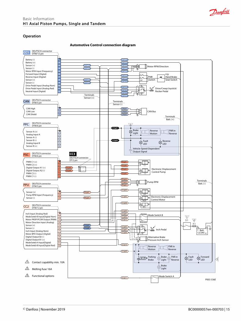
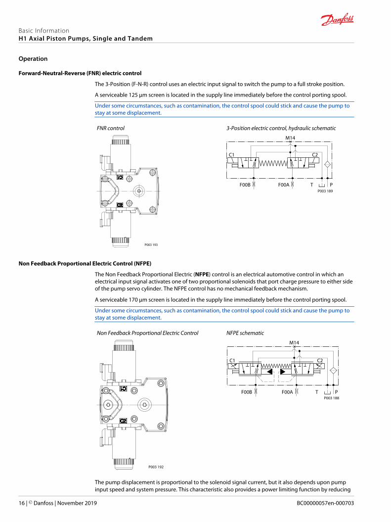
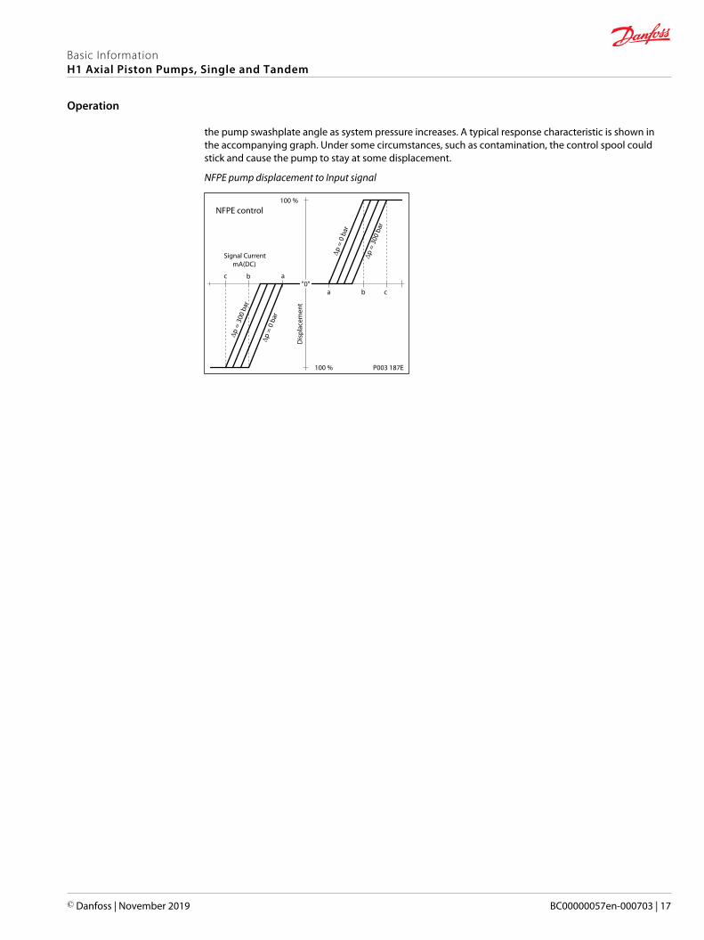
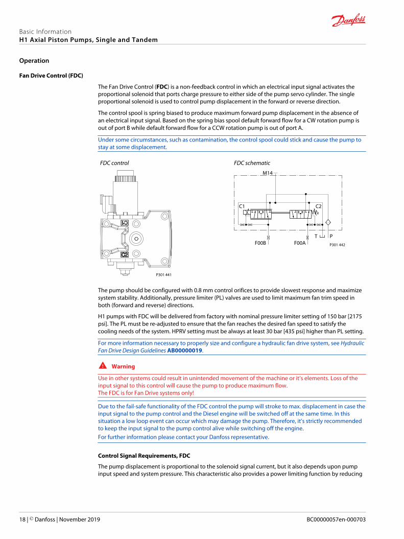
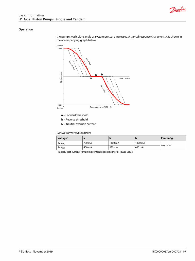
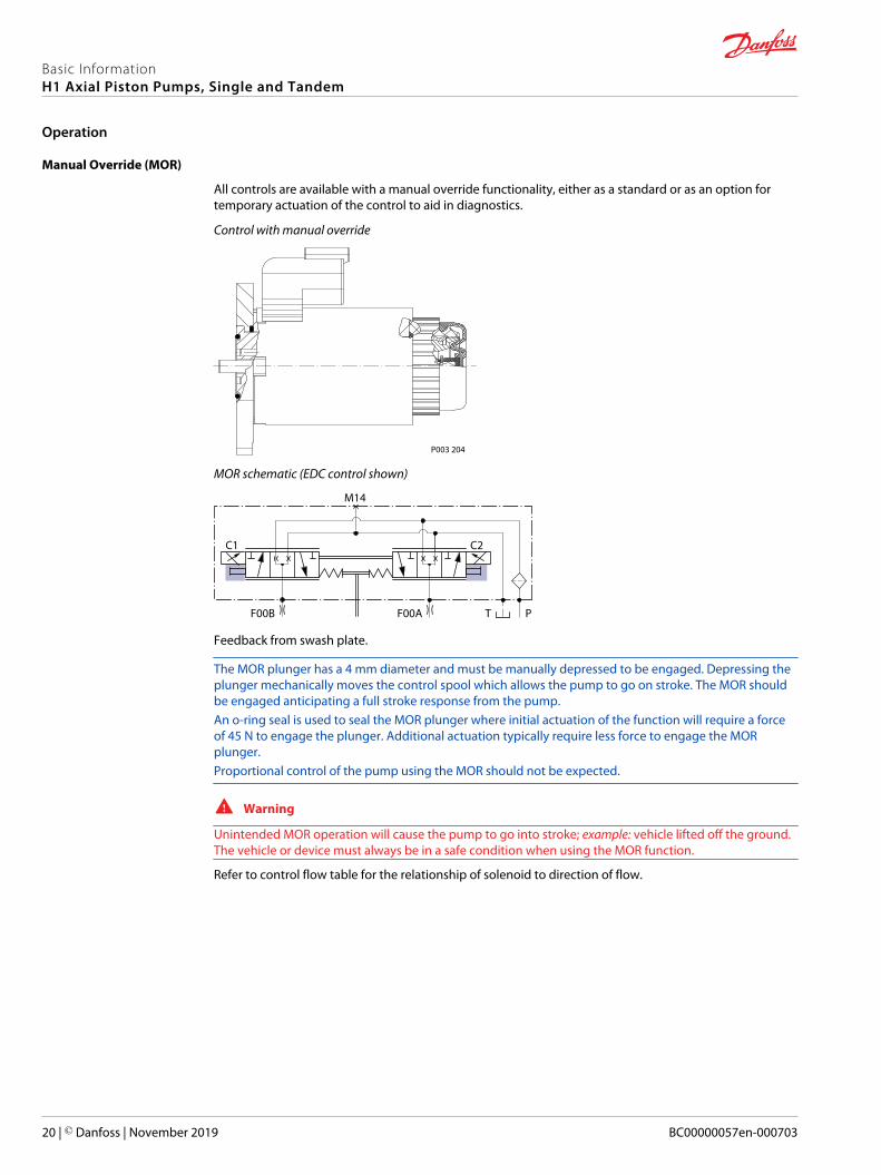
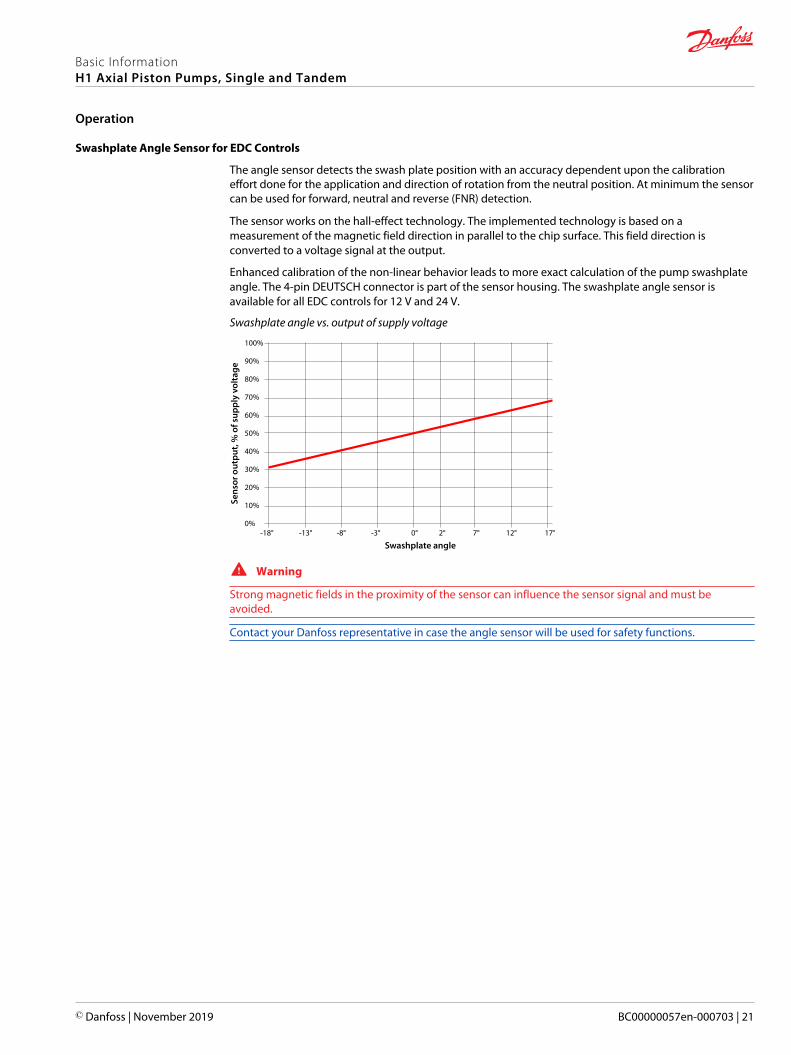
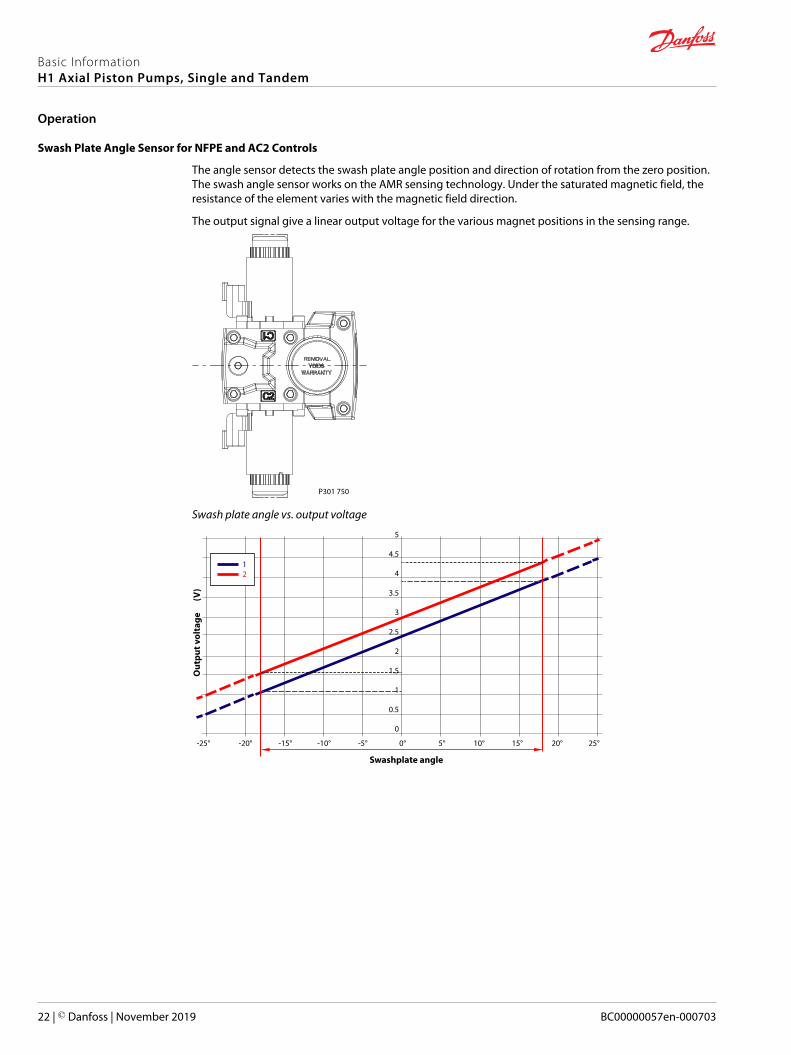
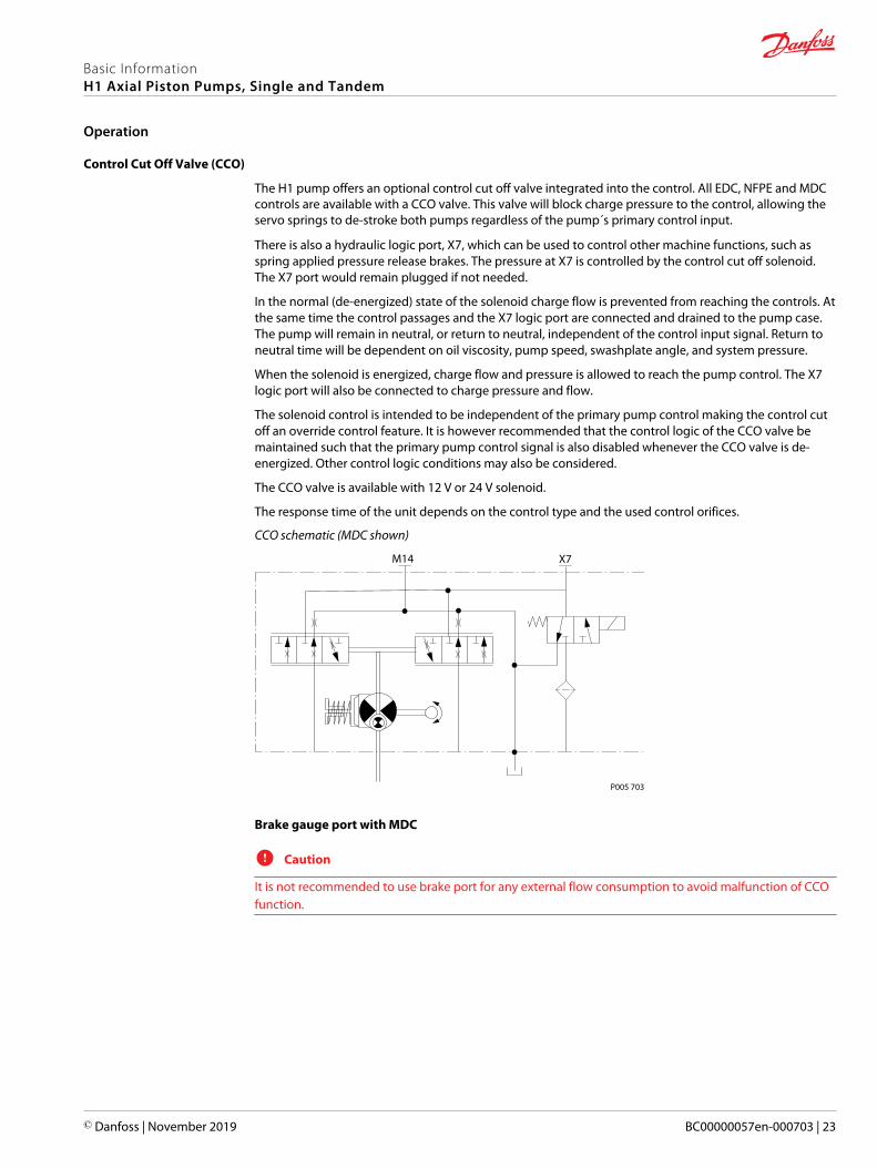
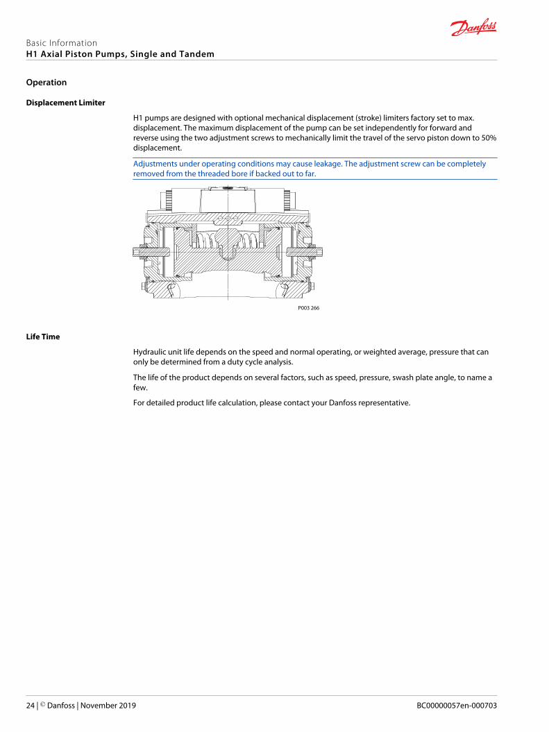
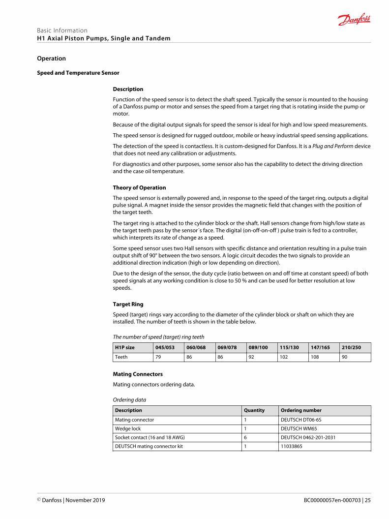
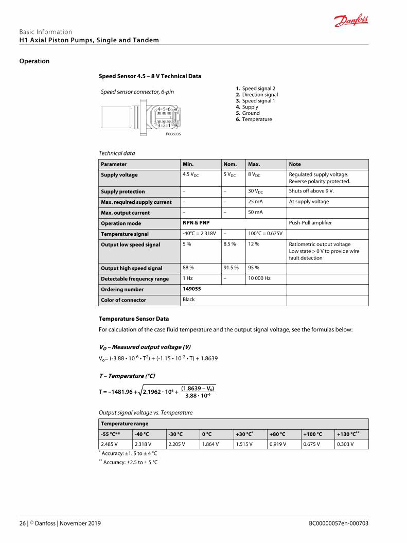
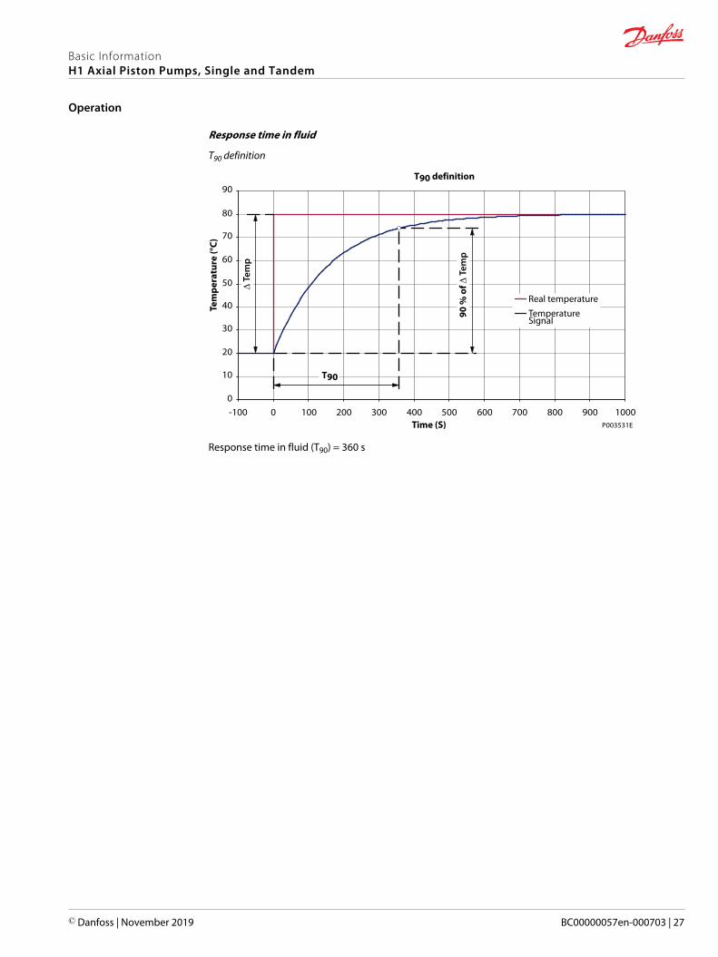
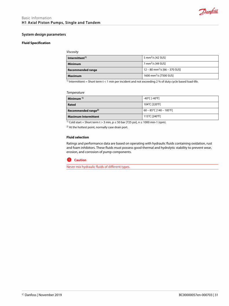
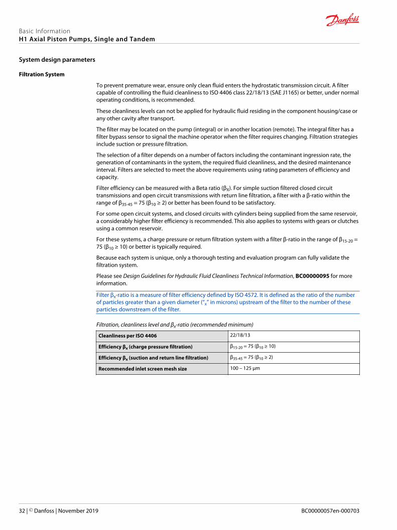
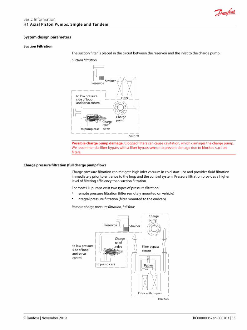
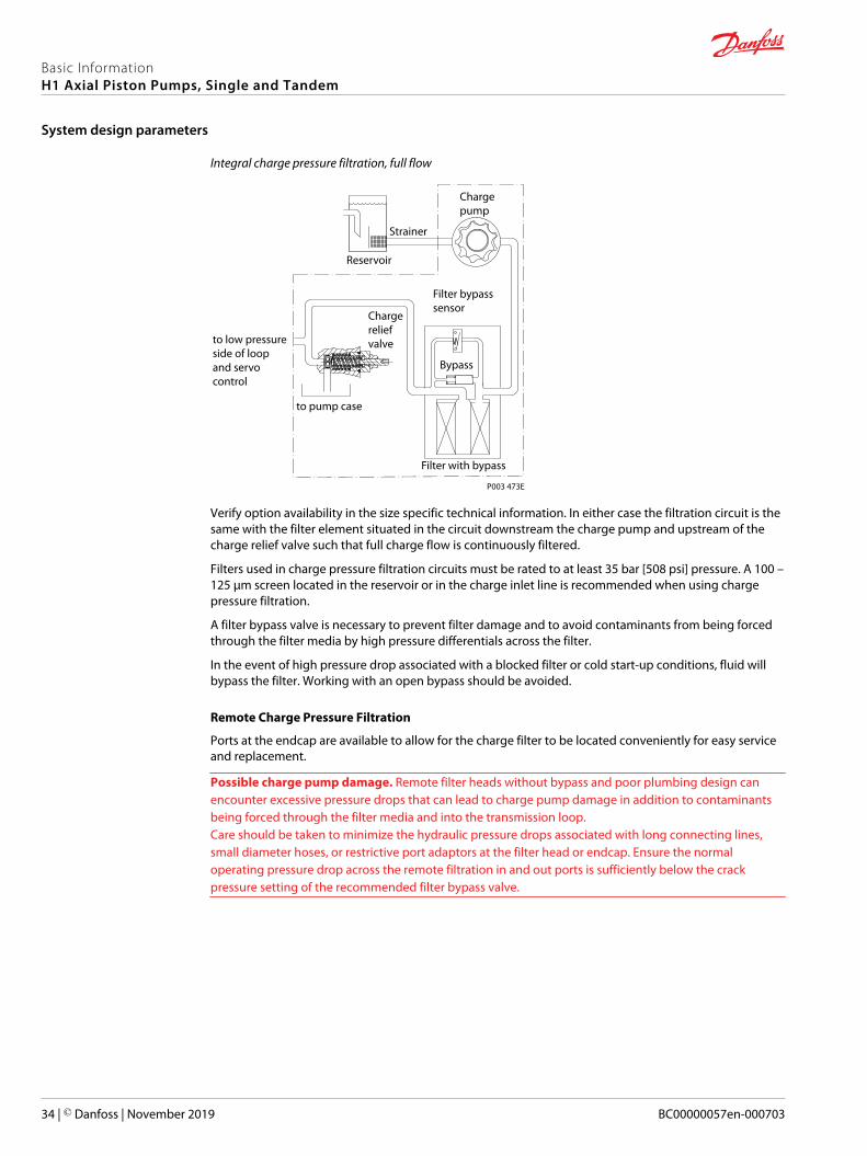
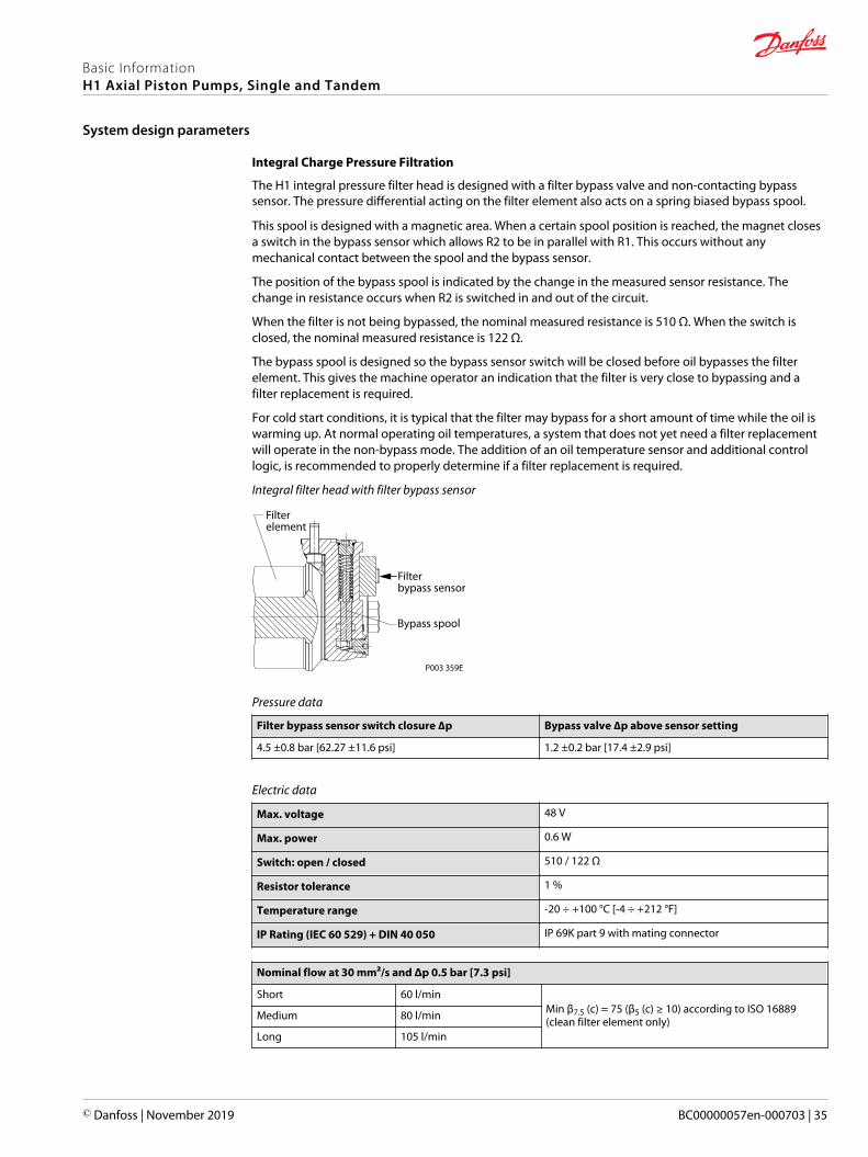
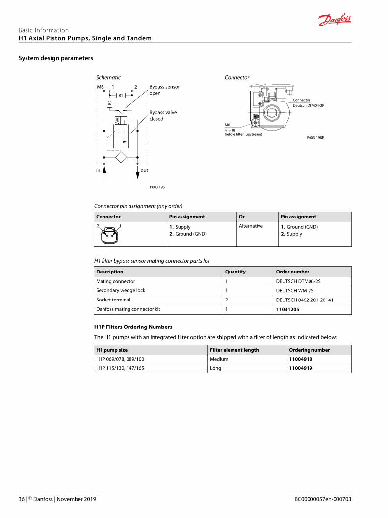
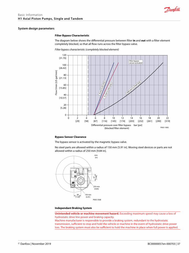
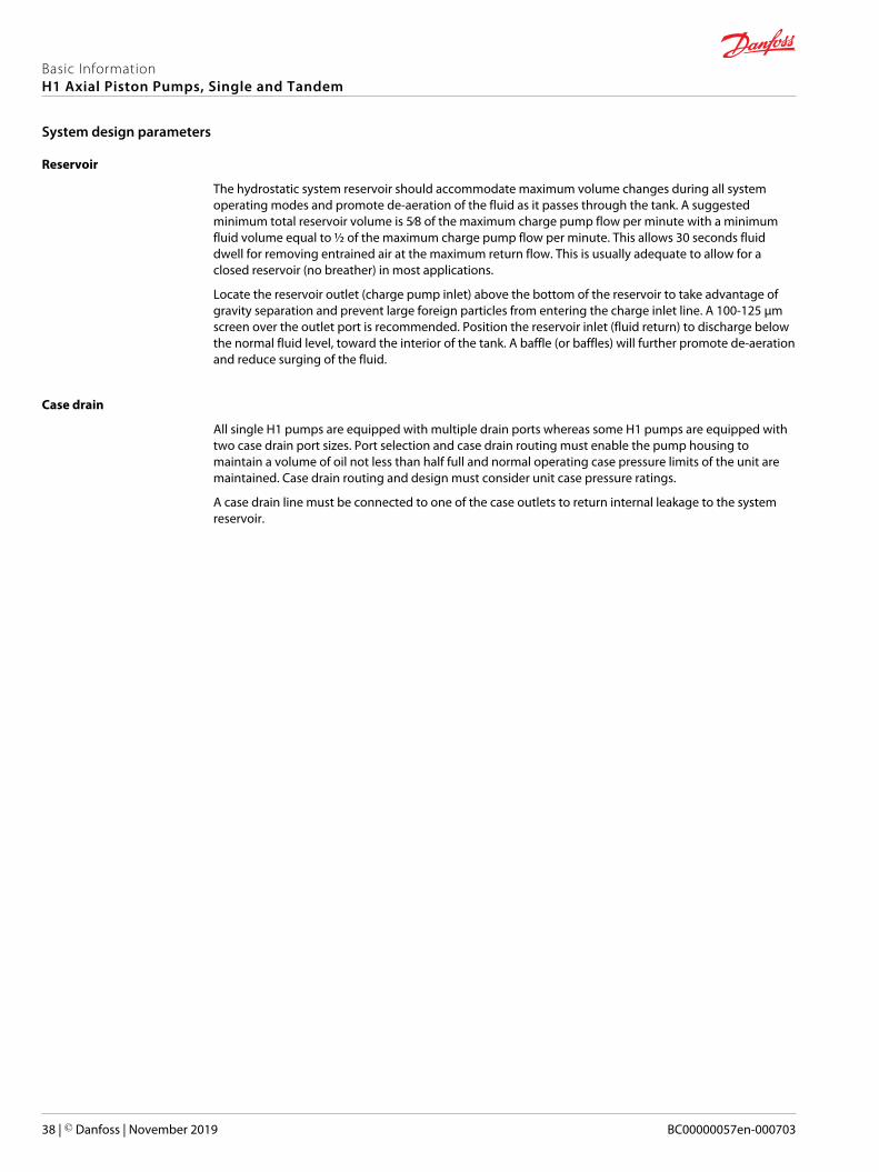
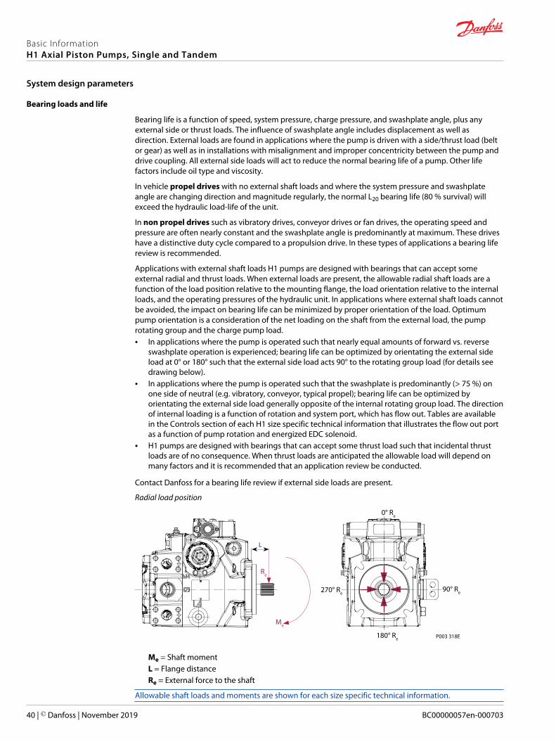
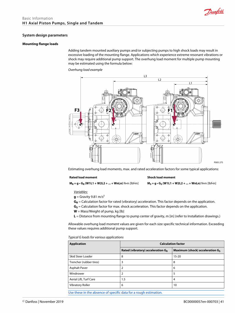
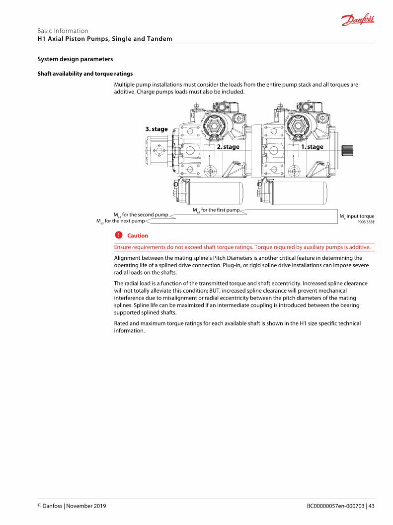
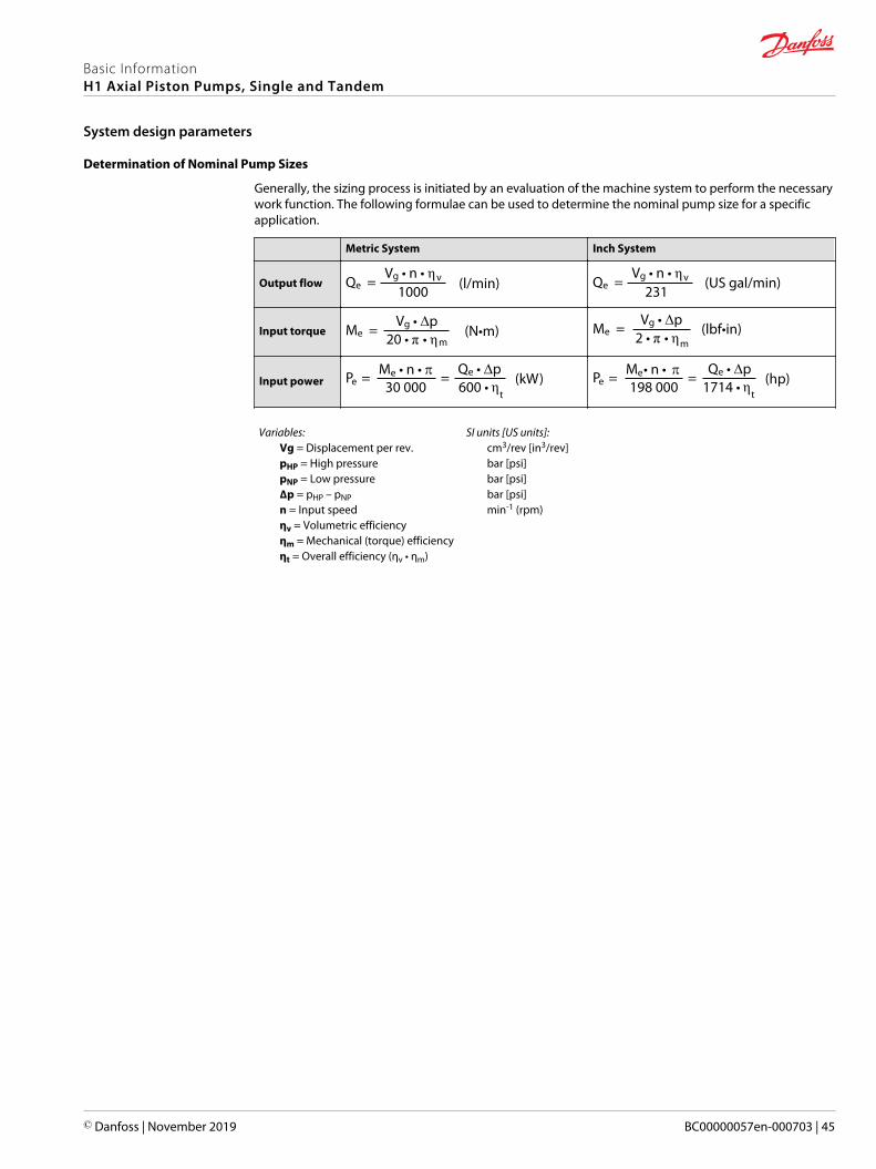