single-crystal neutron diffraction at the australian ... · single-crystal diffraction is a widely...
TRANSCRIPT

Single-Crystal Neutron Diffraction at the
Australian Replacement Research Reactor
Report of the Single-Crystal Diffraction Workshop
ANSTO
11-12 December 2001

2
Single-Crystal Neutron Diffraction at the
Australian Replacement Research Reactor
Report prepared by the participants of the Single-Crystal Diffraction Workshop,
held at ANSTO, 11-12 December 2001
Edited by Wim T. Klooster
E-mail: [email protected]
Contents
Executive Summary 3
1. Introduction 5
2. Scientific Case 5
3. Instrument Requirements 11
4. Desired Performance Specifications 22
5. Other Discussions 23
6. Summary 24
7. References 25
Appendix A: Participants List 26
Appendix B: Workshop Program 27
Appendix C: Characteristics of Image-Plate Detectors 29
Appendix D: Education 30
Figure front page: Structure of IrH(H2)(Cl)2[P(iPr)3]2 (Albinati et al. JACS, 115, 7300-7312,
1993).
3
Executive Summary
Australia has a diverse community of users of single-crystal neutron diffraction. A quasi-
Laue image-plate diffractometer allows the fastest throughput by far, but would exclude an
important number of experiments. Most of these could be covered by the additional
possibility to locate the image-plate detector on a monochromatic beam. Therefore we
recommend both a white thermal beam and a monochromatic beam for an image-plate
detector. At little additional cost the existing 2TanA instrument could be located semi-
permanently on the same monochromatic beam, thus offering three quite different types of
single-crystal instruments. Small improvements could be made to the 2TanA instrument to
cater for the remaining experiments not suited to an image-plate diffractometer.
A quasi-Laue diffractometer would need to be located at the end of a neutron guide. A
bender may be technically possible, but estimated losses of 50-70% of the thermal
neutron beam are too high.
The user community needs a variety of sample environments.
An Instrument Advisory Team will be assembled, and will help in specifying, designing
and commissioning the instrument.
Model of the Replacement Research Reactor.

4
The workshop for the Replacement Research Reactor Project was held
11-12 December 2001 at ANSTO, Lucas Heights, NSW 2234, Australia.
The subject was single-crystal neutron diffraction.
The purpose of the workshop was to:
• identify the future needs and opportunities for single-crystal neutron diffraction, and
• specify instrument requirements
This document represents the accumulated views of the participants at the workshop.
Back Row (left to right): Jane Hanrahan, Erich Kisi, Trevor Finlayson, Darren Goossens,Colin Weeks, Appadurai Thiyakesan, Andrew Goodwin, Peter Turner , Steve Best
Middle Row (left to right): Dai Hibbs, Leonard Lindoy, Robert Burns, Linda Xiao, GeethaRajaratnam, Ross Piltz, Brian Figgis, Jenny Forrester, Andreas Ostermann, Jeff Sellar,Mark Spackman, Suzanne Hughes, Greg Halder, Rob Robinson
Front Row (left to right): Richard Welberry, Sax Mason, Garry McIntyre, ChristinaHoffmann, Tony Klein, Hans Freeman , Wim Klooster
The participants and their affiliations are listed in Appendix A. The workshop program islisted in Appendix B.

5
1. Introduction
Single-crystal diffraction is a widely used technique to study structural properties of
materials. This is mostly done using X-rays. Neutron single-crystal diffraction is less
commonly used because of the special facilities needed. However, neutron single-crystal
diffraction can be essential to study certain features, which can not be studied using other
methods. The need for neutron single-crystal diffraction has been recognised and led the
Beam Facility Consultative Group (BFCG) to recommend a new single-crystal
diffractometer for the Australian Replacement Research Reactor Project.
This document outlines the scientific case for a single-crystal diffractometer, the desired
specifications, and other issues associated with the operation.
2. Scientific Case
2.1 Overview
The proposal for single-crystal neutron diffraction at the Replacement Research Reactor
(RRR) is relevant to the interests of chemists, physicists, materials scientists, geologists,
biologists and others.
The availability of highly accurate structural data has revolutionised chemical and
biological sciences. Data of this sort are predominantly obtained using X-ray and neutron
diffraction techniques, where the information provided by these experiments is
complementary.
The accurate determination of atomic positions in a wide variety of crystalline solids is a
core activity of any neutron diffraction facility. This has been an important area of study by
Australian based research groups and these activities have been conducted at a range of
neutron sources including HIFAR, ISIS and ILL. It is anticipated that the demand for the
structural information provided by these experiments will expand in the future.
The recent rapid expansion of topical areas of chemistry, such as supramolecular
chemistry, crystal engineering and molecular modelling, requires accurate fundamental
information concerning weak intermolecular interactions involving hydrogen atoms.

6
Neutron diffraction provides the means for full characterisation of such interactions in the
solid state.
Important advantages of neutrons which are of particular relevance to structure
determination, stem from the fact that neutrons are primarily scattered by the nucleus,
rather than the electron cloud of an atom. Thus the neutron scattering length of an atom is
not simply proportional to the atomic number and the form factor for neutrons falls off
more slowly with scattering angle than occurs with X-rays. Moreover, the magnetic
moment associated with the neutron gives rise to magnetic scattering, enabling more
detailed characterisation of magnetic materials.
Neutrons play a critical role in the determination of hydrogen atom positions. This is
essential for the characterisation of hydrogen bonding interactions in solids (biology,
chemistry), metal hydrides (catalysis) and organic compounds (drugs, chemistry, biology).
Light atoms such as hydrogen can be located as precisely as, and in the presence of,
heavy atoms such as uranium or platinum.
Another limitation of X-ray techniques arises in instances where it is necessary to
distinguish between elements of similar atomic number. In many cases the neutron
scattering lengths differ markedly and provide a high level of contrast between such atom
types. The contrast also applies for different isotopes of the same element.
Thus, neutron crystallography is capable of providing important structural information that
can not be obtained by X-ray diffraction.
Types of materials to be studied by single-crystal neutron diffraction in the context of
Australian research needs include:
• Organic compounds, including biologically important species
• Inorganic solids, organometallic complexes and coordination compounds
• Framework solids
• Metals and alloys
• Minerals
• Biological and synthetic polymer fibres
• Incommensurate solids
• Supramolecular structures

7
Other aspects of single-crystal neutron diffraction of particular interest to the Australian
scientific community are:
• Charge density studies
• Phase transitions
• Hydrogen bonding
• Diffuse scattering
• Magnetic structures
• Diffraction physics
• The influence of temperature, pressure, electric and magnetic fields on materials
The above types of research will be carried out at the RRR single-crystal neutron facility
from day 1.
2.2 Projected Development
The RRR will provide the opportunity for Australian investigators to play a role in
expanding the range of neutron diffraction applications. Areas in which the existing
expertise and interests of the Australian scientific community may make significant
contributions are:
• The improvement of the sensitivity of the techniques, resulting in shorter measurement
times and/or the ability to record data from smaller crystal specimens than are
currently required.
• An extension of static neutron diffraction studies to time-resolved measurements.
If even one of these two advances were implemented, the application of neutron
diffraction techniques (not just in Australia) would be greatly expanded.
2.3 Diffuse Scattering
Diffuse scattering is the weak background scattering that occurs in the diffraction patterns
of all real crystalline materials from the simplest, e.g. NaCl, to the most complex
8
macromolecule (e.g. protein). While the strong sharp diffraction peaks in the pattern are
used by conventional crystallography to deduce the average repetitive arrangements of
atoms in crystals, diffuse scattering contains information about the deviations from the
average. Quite often it is just these deviations from the average, or types of disorder,
rather than the average structure itself, that give materials their unique or novel properties.
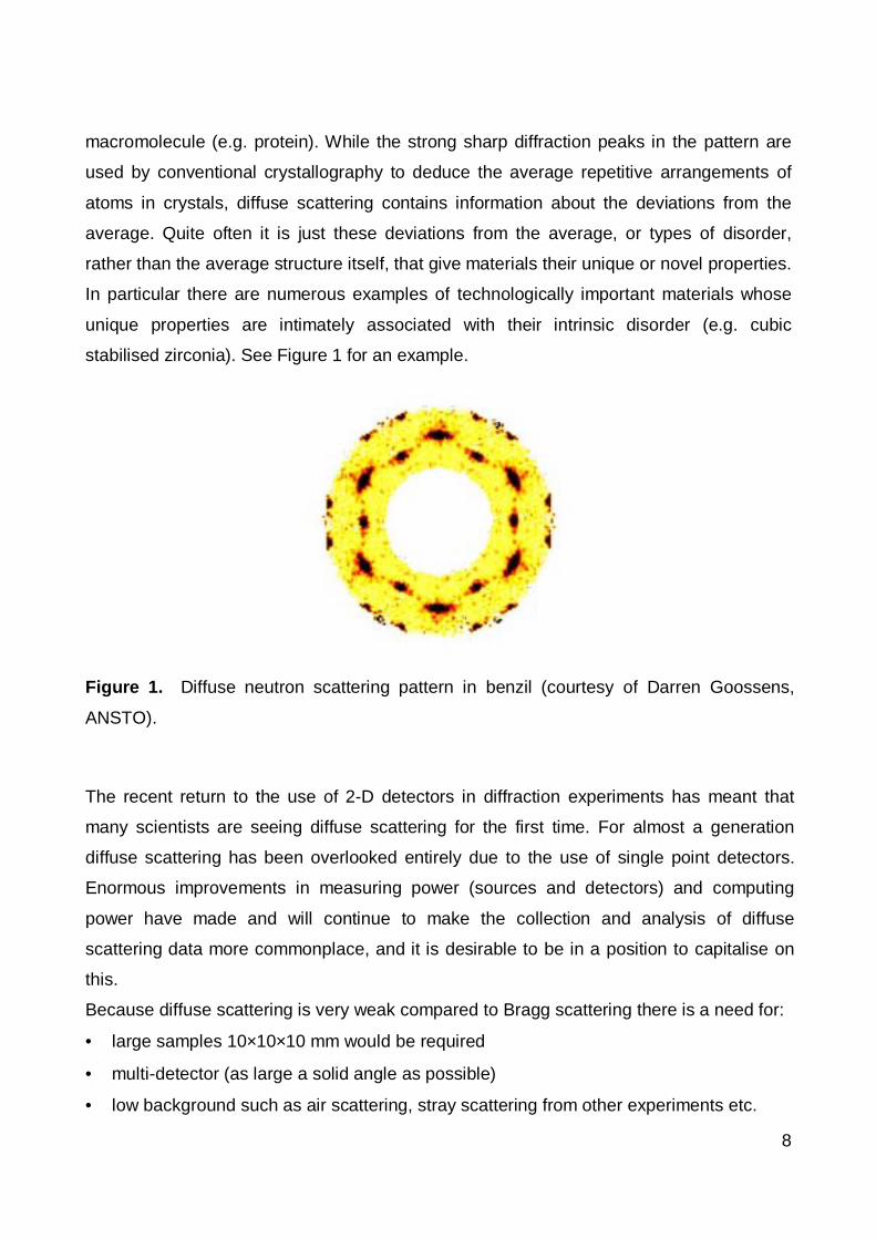
In particular there are numerous examples of technologically important materials whose
unique properties are intimately associated with their intrinsic disorder (e.g. cubic
stabilised zirconia). See Figure 1 for an example.
Figure 1. Diffuse neutron scattering pattern in benzil (courtesy of Darren Goossens,
ANSTO).
The recent return to the use of 2-D detectors in diffraction experiments has meant that
many scientists are seeing diffuse scattering for the first time. For almost a generation
diffuse scattering has been overlooked entirely due to the use of single point detectors.
Enormous improvements in measuring power (sources and detectors) and computing
power have made and will continue to make the collection and analysis of diffuse
scattering data more commonplace, and it is desirable to be in a position to capitalise on
this.
Because diffuse scattering is very weak compared to Bragg scattering there is a need for:
• large samples 10×10×10 mm would be required
• multi-detector (as large a solid angle as possible)
• low background such as air scattering, stray scattering from other experiments etc.

9
(Note: what Bragg scatterers call backgound might be the signal. Because of low counting
statistics, subtracting background is problematical.)
For a reactor source it is necessary to have a monochromatic beam with low ∆λ/λ and
beam divergence, ideally giving the possibility of resolving features in the diffraction
pattern corresponding to spacings of ~100 Å in the sample. For instance, for a 10 Å cell
we need to sample at intervals of 0.1 in the reciprocal cell.
There is also a need to record a wide range of diffraction angles (d-spacings) in order to
be able to determine disorder effects due to displacements.
2.4 Charge density studies
Another area of particular interest is that of charge density studies, where X-ray and
neutron data are combined to obtain the electron distribution and derived properties. See
Figure 2 for an example. The data need to be as accurate as possible, with esd’s for bond
lengths of order 0.001 Å. This necessitates good quality crystals, and a diffractometer like
2TanA, preferably with single counter detector. Image plates may be an option for the
future if the accuracy improves sufficiently. The data must be collected at low
temperature, but that will pose no problems.
Figure 2. Charge density in a carbene (Arduengo et al. JACS, 116, 6812-6822, 1994).

10
2.5 Time-dependent studies
To study time-dependent phenomena one requires study of a particular feature of the
scattering from the crystal (either the intensity of a particular set of diffraction peaks or the
diffuse scattering) as a function of time (on the scale of hours). An image plate
diffractometer is well suited for that.
2.6 Magnetism
A magnetic field is of interest specifically to the class of materials which exhibit strong
magnetostrictive components and offer the possibility of having a response in an applied
magnetic field. The experimental requirements for this will be to apply the magnetic field
(typically from an electromagnet) to the sample being held at a particular temperature in
the Displex cryostat.
Magnetism could be served by other instruments quite well (polarisation analysis, TAS,
HIPD, HRPD). However, it would still be possible to do 3-dimensional magnetic structures
on the new single-crystal diffractometer.
2.7 Biology
A workshop on Neutrons in Biology was held 10-11 July in Melbourne,
(http://home.ansto.gov.au/ansto/neut/bio.pdf) and one of the recommendations was that
there be no specific effort to provide high-resolution protein-crystallography facilities at the
RRR, but that a watching brief be kept on instrumentation and sample-preparation
technologies elsewhere.
Figure 3. Cu-Alanine complex (courtesy of Ross Piltz, ANSTO).

11
3. Instrument Requirements
3.1 To build a 4-circle diffractometer or quasi-Laue diffractometer?
This is an important question. Different types of studies can be done with different types of
diffractometer (Table 1).
Table 1. List of fields with the most suited type of diffractometer.
4-circle quasi-LaueHigh throughput chemistry "routine structural" XH-bonding X XDiffuse scattering XSmall biological molecules X XLow temperatures and highly accurate structures XSmall molecules X XCharge density studies XKinetic studies XSmall crystals XFibre Diffraction XLiquid Crystal XBio(macro)molecules X XGeology XPhase transitions X possiblyMagnetic structures XMultilayers XThin films XEsd 0.001 Å on a bond length X possibly3-d peak shape studies XIncommensurates and quasi-crystals XDiffraction physics XHighly accurate cell dimensions vs environmental parameters XTexture studies XHigh pressures and temperatures X
Note that a monochromatic image plate machine could do a lot of these things. It would beslower than a quasi-Laue diffractometer, but faster than a 4-circle diffractometer.
A quasi-Laue diffractometer is more like a workhorse machine. Faster and cheaper, but
less flexible. Accuracy is not quite the same as for 4-circle diffractometer, but is still
improving and esd’s on bond lengths of ~0.002 Å are possible. The extra data from a
quasi-Laue diffractometer may make up for lower precision in some ways. A 4-circle
diffractometer can be reconfigured in many ways, and is flexible, which require more user
input. Australia has a small but diverse user community, which suggests a flexible option.
12
There are several possible visions:
• 4-circle diffractometer only
• quasi-Laue image-plate diffractometer only
• quasi-Laue + monochromatic image plate diffractometer
• quasi-Laue image-plate diffractometer + 4-circle diffractometer
• quasi-Laue + monochromatic image plate diffractometer + 4-circle diffractometer
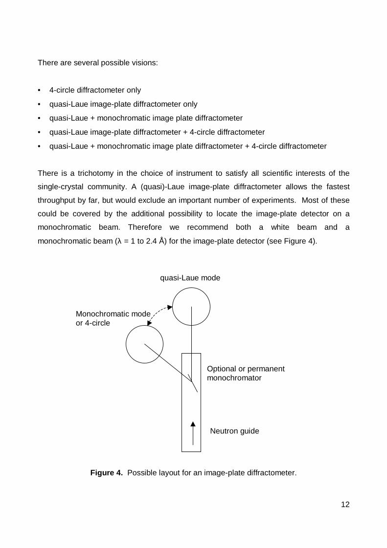
There is a trichotomy in the choice of instrument to satisfy all scientific interests of the
single-crystal community. A (quasi)-Laue image-plate diffractometer allows the fastest
throughput by far, but would exclude an important number of experiments. Most of these
could be covered by the additional possibility to locate the image-plate detector on a
monochromatic beam. Therefore we recommend both a white beam and a
monochromatic beam (λ = 1 to 2.4 Å) for the image-plate detector (see Figure 4).
Figure 4. Possible layout for an image-plate diffractometer.
Monochromatic modeor 4-circle
Neutron guide
quasi-Laue mode
Optional or permanentmonochromator
13
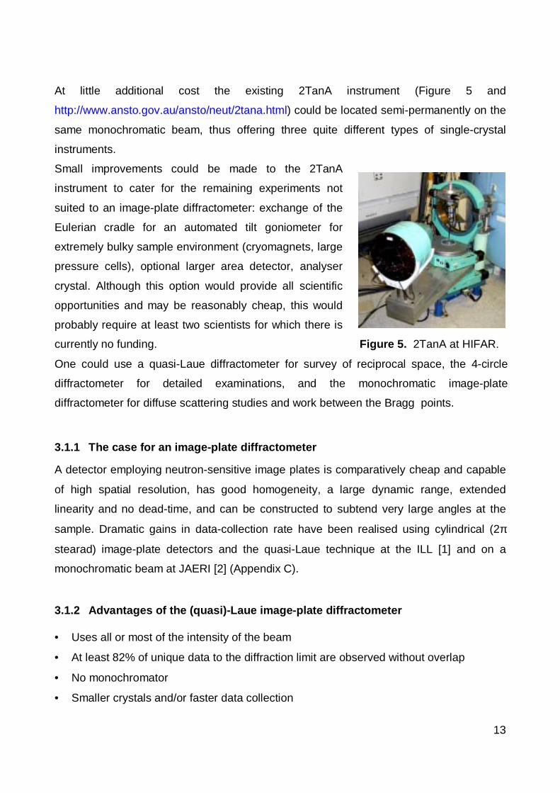
At little additional cost the existing 2TanA instrument (Figure 5 and
http://www.ansto.gov.au/ansto/neut/2tana.html) could be located semi-permanently on the
same monochromatic beam, thus offering three quite different types of single-crystal
instruments.
Small improvements could be made to the 2TanA
instrument to cater for the remaining experiments not
suited to an image-plate diffractometer: exchange of the
Eulerian cradle for an automated tilt goniometer for
extremely bulky sample environment (cryomagnets, large
pressure cells), optional larger area detector, analyser
crystal. Although this option would provide all scientific
opportunities and may be reasonably cheap, this would
probably require at least two scientists for which there is
currently no funding. Figure 5. 2TanA at HIFAR.
One could use a quasi-Laue diffractometer for survey of reciprocal space, the 4-circle
diffractometer for detailed examinations, and the monochromatic image-plate
diffractometer for diffuse scattering studies and work between the Bragg points.
3.1.1 The case for an image-plate diffractometer
A detector employing neutron-sensitive image plates is comparatively cheap and capable
of high spatial resolution, has good homogeneity, a large dynamic range, extended
linearity and no dead-time, and can be constructed to subtend very large angles at the
sample. Dramatic gains in data-collection rate have been realised using cylindrical (2π
stearad) image-plate detectors and the quasi-Laue technique at the ILL [1] and on a
monochromatic beam at JAERI [2] (Appendix C).
3.1.2 Advantages of the (quasi)-Laue image-plate diffractometer
• Uses all or most of the intensity of the beam
• At least 82% of unique data to the diffraction limit are observed without overlap
• No monochromator
• Smaller crystals and/or faster data collection

14
• Simple experiments (as easy as powder diffraction)
• One axis, thus simplifying sample environment
• Pretty, educational, patterns
3.1.3 Disadvantages of the (quasi)-Laue diffractometer
• Higher background
• Indexing can occasionally be difficult
• Harmonic overlap, especially of small-Q data
• Not at all suitable for diffuse scattering
•• Wavelength-dependent corrections e.g. absorption, extinction
3.1.4 Applications already demonstrated at the ILL [3]:
• Rapid structural studies: Gains in efficiency between one and two orders of
magnitude compared with monochromatic experiments on the same or similar
compounds have been achieved, with only modest loss of precision in bond lengths
and angles. Often the precision in a rapid experiment is sufficient to allow physically
meaningful conclusions to be drawn concerning chemical or physical properties [4].
• Compounds containing hydrogen: Even compounds with a hydrogen content of
50% or more give clear interpretable diffraction patterns despite the large inherent
incoherent background [4,5].
• Reciprocal-space surveys: The large detector surface combined with the white beam
allows rapid survey of large continuous regions of reciprocal space, and facilitates
identification of complex features due to incommensurability and twinning [6,7].
• Very small samples: Crystal volumes of 0.1 mm3 or less are now feasible because of
the gain in efficiency over monochromatic experiments. This is particularly attractive
for high-pressure experiments, or for first investigations of topical new materials when
the crystals initially produced are small.
• Phase transitions: Complete data collections are possible in just an hour or so, which
allows the nuclear or magnetic structures to be followed in detail with temperature,
(magnetic or) electric field or pressure, for example, through phase transitions [8].

15
This is particularly relevant to crystal structures where individual reflections are not
directly related to the order parameter.
• Maximum-entropy reconstruction: About 18% of the unique data, mostly at low Q,
are absent from or harmonically overlapped in the Laue diffraction pattern. Maximum-
entropy reconstruction was successful in circumventing this problem to obtain a model-
free density distribution of rotationally disordered molecules [9]. Similar techniques
might make possible ab-initio structure solution from Laue data.
3.1.5 Construction details
The image-plate detector should be very similar to
that of VIVALDI (Very-Intense Vertical-Axis Laue
Diffractometer; for more information see
http://www.ill.fr/YellowBook/VIVALDI/) at the ILL. The
axis of the detector should be vertical to facilitate the
use of heavy cryostats, furnaces and pressure cells,
and the cryostats and furnaces should be top loading
to minimise loss of beam-time between samples or
experiments, and quick exchange of the entire
cryostat or furnace should be possible. Figure 6. VIVALDI at ILL.
A neutron beam with low γ-ray background is essential since (present) image plates are γ-
ray sensitive and would otherwise need extensive protection; γ-rays in the beam itself are
simply transmitted. With present bender technology an end position is essential. A free
path length of about 2 m should be allowed before the detector for insertion of optional
wavelength band-pass filters [10] for exclusion of longer wavelengths that contribute little
to the reflections, or for selection of longer wavelengths for experiments on reflections at
small Q that would otherwise be harmonically overlapped.
The height of the instrument must be variable to allow the detector to be moved to other
beams, e.g. to a cold-neutron guide for experiments at much longer wavelengths.
One can allow the possibility for either replacing the four-circle diffractometer with the
image-plate detector or for placing the image-plate detector behind the four-circle
diffractometer for monochromatic image-plate experiments e.g. of diffuse scattering. The
beams should therefore be close enough to permit this by movement on air-pads and

16
without breaking electrical connections. Positioning the instrument on either beam should
be reproducible.
3.2 Location
3.2.1 Thermal or Cold Neutrons
At the Neutrons in Biology workshop, 10-11 July 2001 in Melbourne,
(http://home.ansto.gov.au/ansto/neut/bio.pdf) it was decided that there is no current need
for a dedicated protein crystallography single-crystal diffractometer. In addition, at the
present single-crystal workshop no significant case was made for cold neutrons. Thus, the
single-crystal diffractometer should be at a thermal beam port. However, even at a
thermal beam it may be possible to collect protein data using a monochromatic beam, like
the BIX machines at JAERI. Also, if the diffractometer is easily movable, it may be
possible to use cold neutrons if user demand changes and an appropriate beam port is
available.
3.2.2 Reactor Face or Neutron Guide
Low noise is important, but a high neutron flux is needed to give the best possible
counting statistics. The number of neutrons is considerably higher at the reactor face
(Table 2). However, the wide divergence of the beam at the reactor face (Table 2) will not
be very useful, since a monochromator cannot accept this full divergence, and will only
add to the background. It would be better to be in the guide hall, where the number of
neutrons in the desired bandwidth with the right divergence is of the same order of
magnitude as at the reactor face, but with considerably lower background. The
wavelength is slightly longer at the neutron guide, due to energy losses. This might be a
consideration in favour of a reactor face position.
Table 2. Calculated neutron flux (Kennedy et al. Applied Physics A, submitted).
Beamline distance (m) flux (n.cm-2.s-1) Wavelength peak (Å) Divergence(°)
TG3 (neutron guide) 49 ~1.6x10⁹ 1.3 2.0
TG4 (reactor face) 6 ~1.6x10¹⁰ 1.1 3.8
* Calculated divergence for beam CG1 at reactor face and neutron guide distances
17
The location at the neutron guide is not so important for a 4-circle or monochromatic
image-plate diffractometer, since they will need a monochromator to extract the right
wavelength neutrons from the beam. However, a quasi-Laue diffractometer should be at
the end of a neutron guide. It might also be possible to locate it elsewhere using a bender.
A bender could give a clean spectrum, but the estimated intensity losses of 50-70% for a
thermal neutron beam are too high, especially if Australia wants to be competitive.
3.3 Monochromator / Velocity Selector
To obtain a monochromatic beam there is a variety of options available.
About half the physics experiments at D10 (ILL) are done using pyrolytic graphite (PG, λ
= 2.35 Å) because of good Q-resolution, good access to magnetic form factor, and good
PG reflectivity.
Chemistry experiments typically use wavelengths in the range λ = 0.9-1.5 Å, but the low
end is limited by the neutron guides. 3 Monochromators are suggested: Cu(220) at
1.235 Å, PG and Ge(11n), n=1,3. BIX (JAERI) uses a bent perfect Si monochromator,
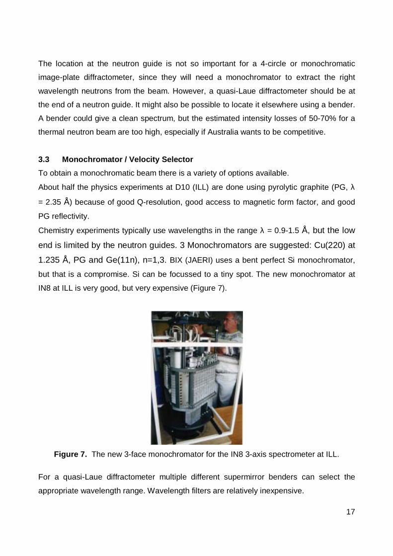
but that is a compromise. Si can be focussed to a tiny spot. The new monochromator at
IN8 at ILL is very good, but very expensive (Figure 7).
Figure 7. The new 3-face monochromator for the IN8 3-axis spectrometer at ILL.
For a quasi-Laue diffractometer multiple different supermirror benders can select the
appropriate wavelength range. Wavelength filters are relatively inexpensive.
18
For short wavelengths one really needs to be at the reactor face, or even better, at a hot
source. Keep this in mind for the future.
3.4 Type of Detector
The neutron flux at RRR will be better than at HIFAR, 2TanA has 6x10⁵ n.cm-2.s-1 at
sample, but the best opportunities for improvement are the detectors.
3.4.1 Image Plates
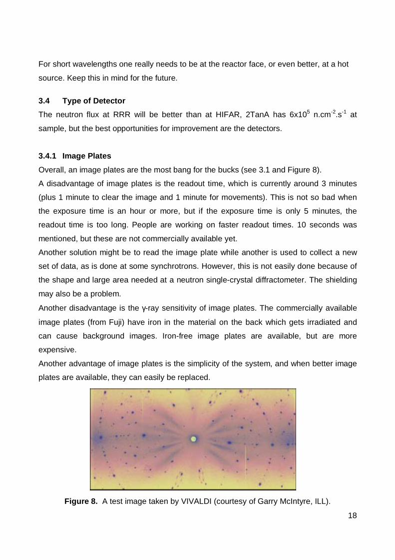
Overall, an image plates are the most bang for the bucks (see 3.1 and Figure 8).
A disadvantage of image plates is the readout time, which is currently around 3 minutes
(plus 1 minute to clear the image and 1 minute for movements). This is not so bad when
the exposure time is an hour or more, but if the exposure time is only 5 minutes, the
readout time is too long. People are working on faster readout times. 10 seconds was
mentioned, but these are not commercially available yet.
Another solution might be to read the image plate while another is used to collect a new
set of data, as is done at some synchrotrons. However, this is not easily done because of
the shape and large area needed at a neutron single-crystal diffractometer. The shielding
may also be a problem.
Another disadvantage is the γ-ray sensitivity of image plates. The commercially available
image plates (from Fuji) have iron in the material on the back which gets irradiated and
can cause background images. Iron-free image plates are available, but are more
expensive.
Another advantage of image plates is the simplicity of the system, and when better image
plates are available, they can easily be replaced.
Figure 8. A test image taken by VIVALDI (courtesy of Garry McIntyre, ILL).
19
3.4.2 Other detectors
A 4-circle diffractometer should aim for an area detector for at least 10 x 10 degrees, with
detector resolution of 1 mm at 50 cm.
Other detector types are possible. For example, 3He gas detectors, multiwire detectors
etc. These are expensive, but could be a future option.
3.4.3 Resolution
The resolution of image plates is nowadays around 200 µm or better, and for gas
detectors about 2 mm. For diffuse scattering experiments the resolution needs to be good.
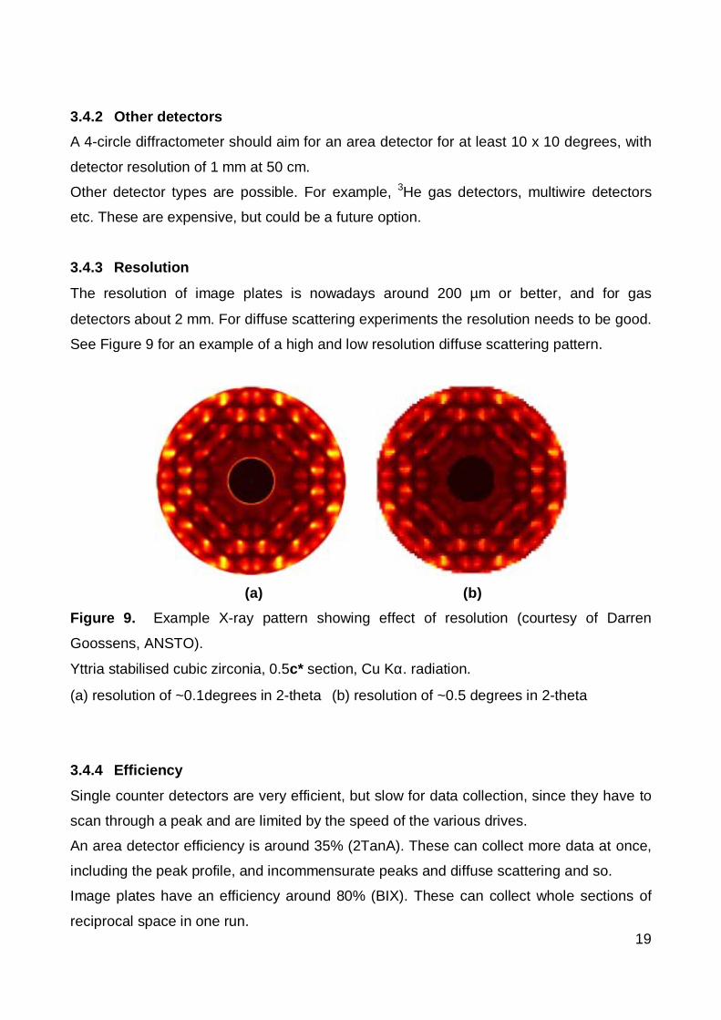
See Figure 9 for an example of a high and low resolution diffuse scattering pattern.
(a) (b)
Figure 9. Example X-ray pattern showing effect of resolution (courtesy of Darren
Goossens, ANSTO).
Yttria stabilised cubic zirconia, 0.5c* section, Cu Kα. radiation.
(a) resolution of ~0.1degrees in 2-theta (b) resolution of ~0.5 degrees in 2-theta
3.4.4 Efficiency
Single counter detectors are very efficient, but slow for data collection, since they have to
scan through a peak and are limited by the speed of the various drives.
An area detector efficiency is around 35% (2TanA). These can collect more data at once,
including the peak profile, and incommensurate peaks and diffuse scattering and so.
Image plates have an efficiency around 80% (BIX). These can collect whole sections of
reciprocal space in one run.
20
Multiwire detectors are 50-100 % efficient (ILL). These type of electronic detectors are
being developed, and can be very good, but are still very expensive.
3.4.5 Background
The general consensus was that the background should be as low as possible. This is
crucial for experiments like diffuse scattering, since the signal is 1000 to 10000 times less
than that of the Bragg peak. A low background is also important for superlattice
reflections. If hydrogen is present in material, it will create its own background. Other
instruments can also cause background. This would strongly suggest a location at the
neutron guide, not at the reactor face.
3.5 Types of ancillaries
Flexibility for various sample environments is desired. In order to facilitate special
environments, a κ-geometry may be necessary.
• Temperature: Displexes down to 1.5 K and furnaces up to 2000 K. Temperature
precision and control of cooling and heating rates is important. In-house support staff
is crucial. A quasi-Laue diffractometer shows considerable background due to cryostat.
If using an image-plate diffractometer, a cryostream as is used in X-ray diffraction
would allow low temperature data to be collected without getting an unwanted signal
from a cryostat or cryorefrigerator. This is particularly useful when looking for weak or
diffuse features and is strongly recommended if a quasi-Laue type machine is built.
Equipment for temperatures less than 1 K (special cryostat) is desirable.
• Pressure: A high pressure cell is desirable, to 1GPa, possibly higher. Also of interest
are particular stress fields (e.g. uniaxial or biaxial). The stress fields can be achieved
through the use of small aluminium clamps. Such clamps need only be of the order of
a centimeter in size, so could easily be accommodated within the sample space of a
Displex cryostat. Such clamps would be constructed by the experimenter, compatible
with the particular crystal.
• Electric Field: An electric field in the order of 50 kV.cm-1 can be applied easily and
cheaply.
21
• Magnetic Field: A magnetic field is more difficult to apply due to the size of the
equipment. No cryomagnet in a quasi-Laue diffractometer due to physical size and
background. For the 4-circle diffractometer a magnetic field of around 10 T could be an
option.
• Chemistry Laboratories: The chemistry laboratories should contain oxygen free,
humidity controlled, gloveboxes. Need the ability to (re-)mount samples on-site. Should
not be a long path (no doors) between glovebox and instrument. Snap freezing of
hydrated crystals (< 1 mm on a side) good for attracting chemists.
• Mounting Crystal: It should be possible to mount and align the crystal off-line, so a
minimum of time is spend putting the crystal on the diffractometer.
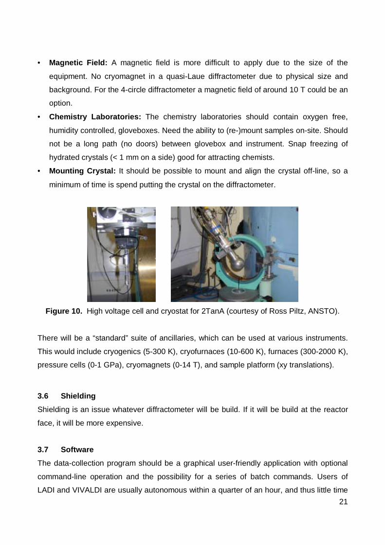
Figure 10. High voltage cell and cryostat for 2TanA (courtesy of Ross Piltz, ANSTO).
There will be a “standard” suite of ancillaries, which can be used at various instruments.
This would include cryogenics (5-300 K), cryofurnaces (10-600 K), furnaces (300-2000 K),
pressure cells (0-1 GPa), cryomagnets (0-14 T), and sample platform (xy translations).
3.6 Shielding
Shielding is an issue whatever diffractometer will be build. If it will be build at the reactor
face, it will be more expensive.
3.7 Software
The data-collection program should be a graphical user-friendly application with optional
command-line operation and the possibility for a series of batch commands. Users of
LADI and VIVALDI are usually autonomous within a quarter of an hour, and thus little time

22
is demanded of the instrument scientist. Analysis of the diffraction patterns at ILL will
mostly be performed with user-friendly software based on the CCP4 Laue suite [11]. Little
assistance is needed for conventional structures. All sorts of users will be using the
software!
GUI, user friendly, data interchange should be easy, consistency across facility. HMI is
held up as excellent example of integrated, consistent and yet flexible software,
C.A.R.E.S.S.
Will there be the opportunity for remote data collection? It is technically possible. This is a
policy decision. People should really come and see for themselves, not necessarily for the
whole experiment if it takes a long time.
4. Desired Performance Specifications
• Versatility
• Speed for a quasi-Laue diffractometer should be roughly one structure per day
• Small sample ~ 0.1 mm3 should be possible
• Experiment turnaround about 10% of experiment time
• Temperature of 1-2000 K, 10-400 K in a cryofurnace
• Solid angle for image-plate diffractometer at least 2π. 4-circle should aim for at least
10 x 10 degrees, with detector resolution of 1 mm at 50 cm
• Dynamic range of detector of at least 1000
• At λ ~ 1.2 Å, ∆λ/λ of about 1-3%, ∆d/d ~ 0.0001
• All angles, positioning precision should be 0.01 degree
• Handle d-spacings up to 40 Å
• Time stability: < 1% decay per week
• Q-range of about 10 (sinθ/λ ~ 0.85 Å-1)
• Low background (1 count per hour per pixel)
• Support services: controlled atmospheres (non-oxidising, wet, dry... all close to
instrument)

23
Other:
• Access is very important: there is a clear need for efficient and unobtrusive security
arrangements, and to ensure the shortest possible time between visitor arrival and
access to instrument.
• User friendly, easy access, remote monitoring, internet connections in rooms in
guesthouse, good food (available on weekends and in evenings), friendly software,
night and weekend ancillary support
5. Other Discussions
• Build a user community. Some attendees had no idea there is a 4-circle diffractometer
at HIFAR. It is important to get many people involved in experiments. This can start by
doing experiments at HIFAR, possibly at other places, and go around the community
to spread the word. Neutron diffraction is still perceived as exotic, whereas in reality it
is as easy as X-ray diffraction.
• Defuse anti-nuclear sentiments through education. Some students should come to
ANSTO to get familiar with neutrons (prepwork for 1 week for example). Possibly
single-crystal diffraction, and simple structures for advanced students. Possibly via the
internet. For a case for educational use of equipment, see Appendix D.
• As much of the hardware as possible should be compatible with the other machines
being developed. This is important for exchangeability of ancillaries. Also, as much of
the software as possible should be compatible with the other machines being
developed.
• All data should be deposited.
24
6. Summary
Australia has a diverse community of users of single-crystal neutron diffraction. A (quasi)-
Laue image-plate diffractometer allows the fastest throughput by far, but would exclude an
important number of experiments. Most of these could be covered by the additional
possibility to locate the image-plate detector on a monochromatic beam. Therefore we
recommend both a white thermal beam and a monochromatic beam (λ = 1 to 2.4 Å) for an
image-plate detector. At little additional cost the existing 2TanA instrument could be
located semi-permanently on the same monochromatic beam, thus offering three quite
different types of single-crystal instruments. Small improvements could be made to the
2TanA instrument to cater for the remaining experiments not suited to an image-plate
diffractometer: exchange of the Eulerian cradle for an automated tilt goniometer for
extremely bulky sample environment (cryomagnets, large pressure cells), optional larger
area detector, analyser crystal.
A quasi-Laue diffractometer would need to be located at the end of a neutron guide. A
bender may be technically possible, but estimated losses of 50-70% of the thermal
neutron beam are too high.
The user community needs a variety of sample environments.
An Instrument Advisory Team will be assembled, and will help in specifying, designing
and commissioning the instrument.

25
7. References
[1] F. Cipriani et al. J. Neutron Res., 4, 79 (1996); N. Niimura et al. Nature Structural
Biology, 4, 909 (1997); D.A.A. Myles et al. Neutron News, Vol. 12.4 (2001).
[2] I. Tanaka et al. J. Phys. Soc. Jpn., 70, 459 (2001) and references therein.
[3] C. Wilkinson et al. Neutron News, Vol. 13.1 (2002).
[4] J.M. Cole et al. Acta Cryst., A57, 429 (2001).
[5] D.A.A. Myles et al. Physica, B241-243, 1122 (1998).
[6] C. Wilkinson et al. J. Magn. Magn. Mater., 217, 55 (2000).
[7] M. Dusek et al. Acta Cryst., B56, 959 (2000).
[8] J.B. Forsyth et al. J. Magn. Magn. Mater., 177-181, 1395 (1998).
[9] P. Schiebel et al. J. Phys.: Condens. Matter, 12, 8567 (2000).
[10] P. Høghøj et al. Nucl. Instr. and Meth. in Phys. Res. B, 160, 431 (2000).
[11] J.W. Campbell et al. J. Appl. Cryst., 31, 496 (1998).
Figure 11. False-colour image of a typical scanned Laue pattern from lysozyme (Niimura
et al., Nature Structural Biology, 4, 909 (1997).
26
Appendix A: Participants List
Participants :
Appadurai Thiyakesan U. of Sydney [email protected] Best U. of Melbourne [email protected] Burns U. of Newcastle [email protected] Figgis UWA [email protected] Finlayson Monash U. [email protected] Forrester U. of Newcastle [email protected] Freeman U. of Sydney [email protected] Goodwin U. of Sydney [email protected] Goossens ANSTO [email protected] Halder U. of Sydney [email protected] Hanrahan U. of Sydney [email protected] Hibbs U. of Sydney [email protected] Hoffmann SNS, USA [email protected] Hughes U. of Sydney [email protected] Hunter ANSTO [email protected] Kennedy ANSTO [email protected] Kim ANSTO [email protected] Kisi U. of Newcastle [email protected] Klein U. of Melbourne [email protected] Klooster ANSTO [email protected] Knott ANSTO [email protected] Lindoy U. of Sydney [email protected] Mason ILL, France [email protected] McIntyre ILL, France [email protected] Ostermann JAERI, Japan [email protected] Piltz ANSTO [email protected] Rajaratnam ANSTO [email protected] Robinson ANSTO [email protected] Sellar Monash U. [email protected] Spackman UNE [email protected] Turner U. of Sydney [email protected] Weeks U. of Sydney [email protected] Welberry ANU [email protected] Xiao UTS [email protected]
Interested :
Shi Dou U. of Wollongong [email protected] Garrett ANSTO [email protected] Ionescu U. of Wollongong [email protected] Kennedy U. of Sydney [email protected] Mei Liu UTSClive Wilkinson ILL, France [email protected]

27
Appendix B: Workshop Program
Program for Workshop on Single-Crystal Diffraction
11-12th December 2001
Conference Room, Building 55, ANSTO, New Illawarra Road, Menai, NSW 2234
Tuesday, 11th December 2001
Purpose:Morning: to outline scientific opportunities, technique and state-of-the-art instrumentation at overseasfacilities.Afternoon: to discuss background issues associated with instrument design specifications.
Time Presentation Presenter Chair
8:30 Arrival at ANSTO
9:00 Opening and Welcome H. Garnett, ANSTO H. Freeman
9:05 An overview of Instrument Opportunities at R.A. Robinson, ANSTO (U. Sydney)
the Australian Replacement Research Reactor
9:30 Charge to the Workshop R.A. Robinson, ANSTO
9:35 Introduction to Single-Crystal Neutron DiffractionW.T. Klooster, ANSTO
10:20 Coffee
10:35 Single-Crystal Diffraction Facilities and Science G. McIntyre, ILL R. Welberry
at the ILL (ANU)
11:20 Single-Crystal Diffraction in the Australian R. Piltz, ANSTO
Context
12:05 Scientific and Technical Visions 5 minutes for each R.A. Robinson
interested attendee (ANSTO)
12:30 Lunch
13:30 Macromolecular Crystallography with A. Ostermann, JAERI S. Best
Monochromized Neutrons: Recent Results from (U. Melbourne)
the Single-Crystal Neutron Diffractometer BIX-3
14:00 D19: a fast monochromatic diffractometer for S. Mason, ILL
single-crystal and fibre diffraction studies in
chemistry, physics and the bio-sciences
14:45 The case for a neutron scattering instrument A. Klein, Melbourne
dedicated to educational use
15:00 Workshop Photo
15:15 Afternoon Tea
28
15:30 Discussion of Scientific Opportunities Forum for discussion L. Lindoy
17:30 Move to Dinner (U. Sydney)
18:00 Workshop Dinner
Wednesday, 12th December 2001
Purpose: to draft Report on the Scientific and Technical Requirements for Single-Crystal Diffraction atAustralia’s Replacement Research Reactor.
9:00 Welcome Back W.T. Klooster, ANSTO
9:05 Characteristics of the Cold, Thermal and Hot S.J. Kennedy, ANSTO B. Figgis
Source and Neutron Guides at the Australian (UWA)
Replacement Research Reactor
9:45 An Overview of the Elastic Scattering C. Hoffmann, SNS
Instruments at SNS with Emphasis on the
Single Crystal Instrument
10:15 Coffee
10:30 Discussion of Single-Crystal Instrument Type Forum for discussion S.J. Kennedy/
11:15 Discussion of Single-Crystal Instrument Design Forum for discussion W.T. Klooster
12:15 Charge for writing Workshop Report R.A. Robinson, ANSTO
12:30 Lunch
13:30 Report writing
16:30 Workshop Summary and Close W.T. Klooster, ANSTO
29
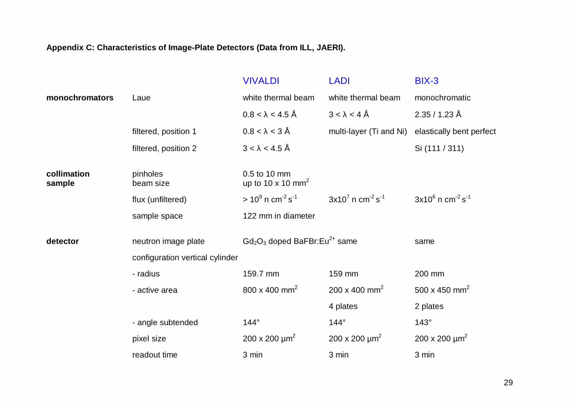
Appendix C: Characteristics of Image-Plate Detectors (Data from ILL, JAERI).
VIVALDI LADI BIX-3
monochromators Laue white thermal beam white thermal beam monochromatic
0.8 < λ < 4.5 Å 3 < λ < 4 Å 2.35 / 1.23 Å
filtered, position 1 0.8 < λ < 3 Å multi-layer (Ti and Ni) elastically bent perfect
filtered, position 2 3 < λ < 4.5 Å Si (111 / 311)
collimation pinholes 0.5 to 10 mm sample beam size up to 10 x 10 mm2
flux (unfiltered) > 109 n cm-2 s-1 3x10⁷ n cm-2 s-1 3x10⁶ n cm-2 s-1
sample space 122 mm in diameter
detector neutron image plate Gd2O3 doped BaFBr:Eu2+ same same
configuration vertical cylinder
- radius 159.7 mm 159 mm 200 mm
- active area 800 x 400 mm2 200 x 400 mm2 500 x 450 mm2
4 plates 2 plates
- angle subtended 144° 144° 143°
pixel size 200 x 200 µm2 200 x 200 µm2 200 x 200 µm2
readout time 3 min 3 min 3 min

1
Appendix D: Education
The case for a neutron scattering instrument dedicated to educational use.
Report to the ANSTO Beam Facilities Consultative group Workshopby
A.G. Klein, School of Physics, The University of Melbourne
1. Introduction.
Since a new research reactor facility is a major national investment, it is importantto maximise its benefits for the largest number of citizens. Beyond its scientific,utilitarian, and political benefits there are educational benefits which can beachieved by involving students in practical, hands-on experimental work usingreactor neutrons. The educational benefits are two-fold: sociological andscientific.
2. The sociological benefits of an educational facility.These revolve around demonstrating that reactors, radiation, nuclear power etc.are not evil and dangerous but when suitably controlled and intelligently handledare a natural extension of physical technology not unlike electricity or, for thatmatter, fire. Ignorance and adverse propaganda have poisoned the minds of awhole generation into attitudes of anti-nuclear hysteria and this may have costour nation dearly (vis-a-vis its Uranium-mining and nuclear-powered economiccompetitors). This state of affairs must not be allowed to continue or to recur ifnuclear power is to gain a foothold in Australia in the 21st Century, as itundoubtedly must. Education to recognise the potential of “clean, safe, nuclearpower” must begin at its source. The largest number of students must be exposedto a modicum of practical learning on the subject, in particular future scientists,future science teachers and future leaders with a scientific education.It is important to note that these sociological benefits are automatic concomitantsof the scientific activities described below.
3. The scientific benefits of an educational facility.These are concerned with concrete contributions to the education of physicalscientists and engineers. I have in mind senior undergraduate students of physics(and possibly chemistry and materials science) coming to Lucas Heights for“practical work” as part of their degree course, possibly in a system administeredby an “undergraduate arm” of AINSE.
Exposure to the environment of a research reactor (even just the guide-hall)contributes (even if tangentially) to students’ knowledge about radiation,

2
including reliable information about safety aspects, shielding, detection andmonitoring, neutrons, fission, beams, etc.
4. Suggested Experiments
In more direct terms, I envisage one or more set projects as “practical work” for,say, 3rd year students as a result of which they become acquainted with manyconcrete aspects of the nuclear field while, at the same time gaining valuableknowledge and skills.
I have in mind an experiment in which a monochromatic beam of thermalneutrons is Bragg diffracted by a large crystal of Sodium Chloride (Silicon isprobably too “perfect” , therefore diffracting too narrow a range of wavelengths).Knowing Avogadro’s number and the density of NaCl, (hence the latticespacing), the neutron deBroglie wavelength can be calculated.
A more interesting variant diffracts the neutrons from a rotating NaCl crystal, withthe diffracted beam intercepted by a crystal of the same material, in the parallel(non-dispersive) configuration, situated at a distance of the order of a metreaway. With timed detection, recorded in a PC connected as a multi-scaler, this iseffectively a time-of-flight measurement, which allows the measurement of theneutron velocity. Thus, with the experimental determination of wavelength as wellvelocity, one can find Planck’s constant (knowing the mass of the neutron) orvice-versa.
ω θ
shielding
shielding
n. guidebeam
θ
While the above is a fairly straightforward laboratory exercise, I hope that itscollateral educational content is obvious. It contains a lot of fundamental physicsas well as a number of valuable laboratory techniques. Furthermore, it cansupport variants, which would make it accessible to a very wide spectrum ofstudents. Ideally, I would like to see every physics major in Australia exposed to it orits equivalent.

3
More advanced exercises can be envisaged using other available beaminstruments, eg. simple structure analysis with a diffractometer; the observation ofan anti-ferromagnetic material structure; a small angle scattering exercise, etc.
I would also recommend one or more similar laboratory exercises involvingirradiation facilities, for example:
* a life-time measurement;* an elementary exercise in activation analysis;* a (non-radioactive) isotope dilution analysis exercise with Indium (might appealto environmental science students !); * an (n,γ) on Nitrogen protein assay on a food sample (might appeal to biologicalscience students).
5. Conclusion
In conclusion, I feel that direct involvement with laboratory exercises in a researchenvironment is a powerful educational opportunity which leads to acquaintancewith and de-mystification of reactor, radiation, neutron and nuclear apparatusand concepts.
3 December, 1997