single-packaged model 604b heat pump sizes 024 … pkg.pdf · single-packaged heat pump units model...
TRANSCRIPT

SINGLE-PACKAGEDHEAT PUMPUNITS
Model 604BSizes 024-060
with Puron® (R-410A) Refrigerant2 to 5 Nominal Tons
Form No. PDS 604B.24.2
Single-Packaged Products with Energy-Saving Features andPuron® refrigerant.• 13 SEER• Up to 8.0 HSPF• 11 EER at 95°F OD• Low Sound Levels• Variable Speed Blower -Standard• Factory Installed TXV
FEATURES/BENEFITS
One-piece Heat Pump unit with optional electric heater, low in-stallation cost, dependable performance and easy maintenance.
EFFICIENT OPERATIONHigh-efficiency design
with SEERs (Seasonal Energy Efficien-cy Ratio) of 13.0.
Puron® Environmentally Sound Refrigerant
is Bryant’sunique refrigerant designed to help protect the environment.Puron is an HFC refrigerant which does not contain chlorine thatcan harm the ozone layer. The most important advantage ofPuron refrigerant is that it has not been banned in future air con-ditioning systems as the traditional refrigerant R-22 has been.Puron refrigerant is in service in over 100,000 systems provinghighly reliable, environmentally sound performance.
Perfect Humidity™ Technology featuring Variable SpeedBlower motors
provides better comfort and energy efficiency.You can expect up to 30 times better dehumidification; economi-cal constant fan for less than $50 a year, which provides improvedindoor air quality and more even temperatures from room to room;and reduced indoor noise due to lower air velocity. In addition,you’ll realize improved installation flexibility with 3 different airflow
choices for best overall comfort.
EASY INSTALLATIONFactory-assembled package
is a compact, fully self-contained,heat pump unit that is pre-wired, pre-piped, and pre-charged forminimum installation expense. 604B units are available in a va-riety of standard capacity ranges with voltage options to meetresidential and light commercial requirements. Units install eas-ily on a rooftop or at ground-level.
DURABLE, DEPENDABLE COMPONENTSCompressors
are designed for high efficiency. Each compres-sor is hermetically sealed against contamination to help promotelonger life and dependable operation. Vibration isolation pro-vides quiet operation. Compressors have internal high-pressureand overcurrent protection.
Convertible duct configuration
Unit is designed for easy usein either downflow or horizontal applications. Each unit is easilyconverted from horizontal to downflow and include horizontalduct covers.
Direct-drive variable speed blower motor
is standard on all604B models.
Direct-drive, PSC condenser-fan motors
are designed to helpreduce energy consumption and provide for cooling operationdown to 55°F outdoor temperature. Motormaster® II low ambientkit is available as a field-installed accessory.
Corporate thermostats
designed to work as a system withBryant’s small packaged product.
Refrigerant system
is designed to provide dependability. Liquidrefrigerant filter driers are used to promote clean, unrestrictedoperation. Each unit leaves the factory with a full Puron® refrig-erant charge. Refrigerant service connections make checkingoperating pressures easier.
Indoor and Outdoor coils
are computer-designed for optimumheat transfer and cooling efficiency. The indoor coil is fabricatedfrom copper tube and aluminum fins and is located inside theunit for protection against damage. The outdoor coil is internallymounted on the top tier of the unit. Copper fin coils and pre-coat-ed fin coils are available from the factory by special order. Thesecoils are recommended in applications where aluminum fins arelikely to be damaged due to corrosion. They are ideal for sea-coast applications.
Thermostatic Expansion Valve
— A hard shutoff, balance portTXV maintains a constant superheat at the evaporator exit (cool-ing cycle) resulting in higher overall system efficiency.
High and Low Pressure Switches
give added safety and reli-ability to the compressor.
Low sound ratings
ensure a quiet indoor and outdoor environ-ment with sound ratings as low as 72 dB.(See page 3.)
Easy to service cabinets
provide easy single-panel accessi-bility to serviceable components during maintenance and in-stallation. The basepan with integrated drain pan provideseasy ground level installation with or without a mounting pad.
UNIT 604B

—2—
Convenient handholds are provided to manipulate the unit onthe jobsite. A nesting feature ensures a positive basepan toroof curb seal when the unit is roof mounted. A convenient 3/4-in. wide perimeter flange makes frame mounting on a rooftopeasy.
Louvered Grille
provides hail and vandalism protection for thecoil.
Downflow operation
is easily provided in the field to allow ver-tical ductwork connections. The basepan utilizes knockout styleseals on the bottom openings to ensure a positive seal in thehorizontal airflow mode.
Cabinets
are constructed of heavy-duty, phosphated, zinc-coat-ed prepainted steel capable of withstanding 500 hrs of saltspray. Interior surfaces of the evaporator and electric heatercompartments are insulated with cleanable semi-rigid insulationboard, which keeps the conditioned air from being affected bythe outdoor ambient temperature and provides improved indoorair quality. (Conforms to American Society of Heating, Refriger-ation and Air Conditioning Engineers No. 62P.) The sloped drainpan minimizes standing water in the drain, which is provided withan external drain.
Standard metal duct covers
with insulation come with the unitand cover the horizontal duct openings. These can be left inplace if the units are converted to downflow.
Short-Cycling protection
for the compressor is incorporatedinto our defrost control board ensuring a five minute delay (+/-2minutes) before restarting compressor after shutdown for anyreason.
TABLE OF CONTENTS
PageFeatures/Benefits . . . . . . . . . . . . . . . . . . . . . . . . . . . . . . . . . 1,2Model Number Nomenclature. . . . . . . . . . . . . . . . . . . . . . . . . . 3ARI Capacities . . . . . . . . . . . . . . . . . . . . . . . . . . . . . . . . . . . . . 3Physical Data . . . . . . . . . . . . . . . . . . . . . . . . . . . . . . . . . . . . . . 4Options and Accessories . . . . . . . . . . . . . . . . . . . . . . . . . . . 5,6Base Unit Dimensions . . . . . . . . . . . . . . . . . . . . . . . . . . . . . 7,8Accessory Dimensions . . . . . . . . . . . . . . . . . . . . . . . . . . . . . . . 9Selection Procedure . . . . . . . . . . . . . . . . . . . . . . . . . . . . . . . . 10Performance Data . . . . . . . . . . . . . . . . . . . . . . . . . . . . . . 11-19Typical Piping and Wiring. . . . . . . . . . . . . . . . . . . . . . . . . . . . 20Application Data . . . . . . . . . . . . . . . . . . . . . . . . . . . . . . . . . . . 21Electrical Data . . . . . . . . . . . . . . . . . . . . . . . . . . . . . . . . . 22, 23Typical Wiring Schematics . . . . . . . . . . . . . . . . . . . . . . . . 24, 25Controls . . . . . . . . . . . . . . . . . . . . . . . . . . . . . . . . . . . . . . . . . 26Guide Specifications. . . . . . . . . . . . . . . . . . . . . . . . . . . . . 27, 28

—3—
MODEL NUMBER NOMENCLATURE
604B N X 024 000 – –
Model Number
604B
– Single Packaged Heat Pump
Electrical SupplyN
– 208/230-1-60
P
– 208/230-3-60
Nominal Cooling Capacity024
– 2 ton
030
– 2.5 ton
036
– 3 ton
042
– 3.5 ton
048
– 4 ton
060
– 5 ton
Options
BT
– AL evap, vinyl condens
CC
– AL evap, CU condens
CU
– CU evap & condens
TP
– Base unit with tin plated indoor coil hairpins
TV
– TP with vinyl coating on outdoor coil
TC
– TP with AL indoor coil & CU/CU out-door coil
Only used if ordering an option
ARI* CAPACITIESCOOLING CAPACITIES AND EFFICIENCIES
UNIT604B
NOMINALTONS
STANDARDCFM
NET COOLINGCAPACITIES
(Btuh)EER@A** SEER†
SOUNDRATINGS‡
(dB)
024 2 800 24,000 11 13.0 72030 2-1/2 1000 28,800 11 13.0 72036 3 1100 36,000 11 13.0 72042 3-1/2 1450 41,000 11 13.0 72048 4 1450 45,000 11 13.0 78060 5 1710 57,000 11 13.0 78
HEATING CAPACITIES AND EFFICIENCIESUNIT604B
HIGH HEAT CAPACITY (BTUH) @ 47°F
HIGH HEAT COP@ 47°F
LOW HEAT CAPACITY(BTUH) @ 17°F
LOW HEAT COP@ 17°F HSPF†
024 24,000 3.4 14,400 2.2 7.8030 29,000 3.4 16,000 2.2 8.0036 36,000 3.4 19,600 2.1 8.0042 40,500 3.4 21,600 2.2 8.0048 47,000 3.5 24,600 2.2 8.0060 55,000 3.4 31,000 2.2 8.0
LEGEND
dB
— Sound Levels (decibels)
db
— Dry Bulb
SEER
—Seasonal Energy Efficiency Ratio
wb
— Wet Bulb
COP
— Coefficient of Performance
HSPF
— Heating Season Performance Factor* Air Conditioning & Refrigeration Institute.
** “A” Conditions– 80°F indoor db/67°F indoor wb and 95°F outdoor db.
† Rated in accordance with U.S. Government DOE (Department of Energy) test procedures and/or ARI Standard 210/240-94.
‡ Tested in accordance with ARI Standard 270-95 (not listed in ARI).NOTES:1. Ratings are net values, reflecting the effects of circulating fan heat.
Ratings are based on:
Cooling Standard:
80°F db, 67°F wb indoor entering-air tempera-ture and 95°F db outdoor entering-air temperature.
2. Before purchasing this appliance, read important energy cost andefficiency information available from your retailer.
AL
— Aluminum
CU
— Copper

—4—
PHYSICAL DATA
* Required filter sizes shown are based on the larger of the ARI (Air Conditioning & Refrigeration Institute) rated cooling airflow or the heating airflow velocity of 300 ft/minute for throwaway type or 450 ft/minute for high-capacity type. Air filter pressure drop for non-standard filters must not exceed 0.08 in. wg.
UNIT SIZE 604B 024 030 036 042 048 060
NOMINAL CAPACITY (ton)
2 2-1/2 3 3-1/2 4 5
OPERATING WEIGHT (lb)
350 350 373 440 463 499
COMPRESSOR
Scroll
REFRIGERANT (R-410A)Quantity (lb)
7.5 8.0 9.5 10.8 11.5 14.0
REFRIGERANT METERING DEVICEOrifice ID TXVOrifice OD (in.)
OD-AccuRater® Piston ID-TXV
TXV0.038 Left
0.046 Right
TXV0.042 Left
0.052 Right
OUTDOOR COILRows—Fins/in.Face Area (sq ft)
2—2112.3
2—2112.0
2—2113.6
2—2115.4
2—2117.4
2—2119.3
OUTDOOR FANNominal CfmDiameter (in.)Motor Hp (Rpm)
270022
1/8 (825)
270022
1/8 (825)
280022
1/8 (825)
280022
1/8 (825)
330022
1/4 (1100)
330022
1/4 (1100)
INDOOR COILRows—Fins/in.Face Area (sq ft)
3—153.7
3—153.7
4—153.7
3—154.7
4—154.7
4—155.7
STANDARD INDOOR BLOWERNominal Airflow (Cfm)Size (in.)Motor (Hp)
80010 x 10
1/2
100010 x 10
1/2
110011 x 10
3/4
140011 x 10
3/4
145011 x 10
3/4
175011 x 10
1.0
HIGH-PRESSURE SWITCH (psig)CutoutReset (Auto.)
610 ± 15420 ± 25
LOSS-OF-CHARGE/LOW-PRESSURE SWITCH (Liquid Line) (psig)CutoutReset (Auto.)
20 ± 545 ± 10
RETURN-AIR FILTERS (in.)*Throwaway
20 x 20 x 1 20 x 20 x 1 20 x 24 x 1 24 x 30 x 1 24 x 30 x 1 24 x 30 x 1
32 5
A2
MA
NU
FAC
TUR
ER
CERTIFIED TO ARI AS COMPLY
ING
WITH
ARI STANDARD 210
UN
ITAR
Y
AIR CONDITIO
NIN
G
EQUIPMENT
OUTDOOR SOUND: OCTAVE BAND DATA—DECIBELS (L w(A))
MODEL NO. 604B
Frequency (Hz) 024 030 036 042 048 060
125
58.8 58.8 60.7 56.7 62.4 63.5
250
63.5 63.5 63.3 62.8 69.9 67.6
500
67.2 67.2 66.8 67.8 71.3 71.8
1000
66.9 66.9 66.5 67.4 73.4 75.5
2000
63.7 63.7 64.2 63.7 70.0 71.0
4000
58.3 58.3 60.3 57.7 66.3 68.1
8000
50.0 50.0 53.0 50.8 60.1 59.9

—5—
Factory-installed options
Coil options
include Tin-Plated* indoor hairpins, copper/copperand vinyl-coated construction for refrigerant coils. Units areshipped standard with copper tube/aluminum fin construction.See model number nomenclature for coil options.*Tin-Plated indoor coils are built with special hairpins that are de-signed to resist both general pitting corrosion and excessive in-door corrosion (Formicary Corrosion).
Field-installed accessories
Economizer with solid-state controls and barometric reliefdampers
includes filter racks and provide outdoor air duringcooling and reduce compressor operation.
Manual outside air damper
includes hood and filter rack withadjustable damper blade for up to 25% outdoor air.
Electric heaters
provide additional heat in the unit when re-quired. Each package has a heater module that slides into thecontrols compartment. Heater sizes range from 5.0 to 20.0 kw.The electric heater design allows the use of a single-point powersupply for the entire unit, resulting in lower installed costs.
Flat roof curbs
in both 8 in. and 14 in. sizes are available forroof mounted applications.
Square-to-round duct transition kit
enables 024-048 sizeunits to be fitted to 14 in. round ductwork.
Thermostats
provide control for the system heating and coolingfunctions. Thermostat models are available in both programma-ble and non-programmable versions.
Lifting kit
includes 4 metal brackets that are used to assist in lift-ing this product onto a roof application.
Crankcase heater
provides anti-floodback protection for low-load cooling applications.
Low-ambient kit (Motormaster II control)
allows the use ofmechanical cooling down to outdoor temperatures as low as0°F.
Filter rack
features easy installation, serviceability, and high-filtering performance for vertical or horizontal applications.
Compressor hard start kit
assists compressor start-up by pro-viding additional starting torque on single phase units and pro-longs compressor motor life.
Economizer with Solid-State Controls and Barometric
Relief Dampers
Manual Air Damper (25% open)
Electric Heaters
Filter Rack
Flat Roof Curbs (8-in. and 14-in.)
Square-to-Round Duct Transition Kit
Thermostats
Crankcase Heater
Low Ambient Kit (Motormaster® II Control)
Lifting Kit
Compressor Hard Start Kit
ELECTRIC HEATERS
LEGENDODS — Order Distribution SystemNOTE: Electric heaters are rated at 240v. Refer to Multiplication Factors table for other voltages.
MINIMUM AIRFLOW FOR RELIABLE ELECTRIC HEATER OPERATION
ODS CATALOGORDERING NO.
NOMINAL CAPACITY (kW)
USED WITH SIZES024 030 036 042 048 060
ELECTRIC HEATERS (208/230 — SINGLE PHASE — 60 Hz)CPHEATER052A00
5.0 X X X X
CPHEATER064A00
5.0 X X
CPHEATER070A00
7.5 X X X X X X
CPHEATER050A00
10.0 X X X X X X
CPHEATER066A00
15.0 X X X X
CPHEATER054A00
20.0 X X X
ELECTRIC HEATERS (208/230 — 3 PHASE — 60 Hz)CPHEATER055A00
5.0 X X X X
CPHEATER056A00
10.0 X X X
CPHEATER068A00
10.0 X
CPHEATER058A00
15.0 X X X X
CPHEATER067A00
20.0 X X X
UNIT-604B 024 030 036 042 048 060AIRFLOW
750 1025 1250 1285 1710 1800
OPTIONS AND ACCESSORIES

—6—
ECONOMIZER
FILTER RACK MANUAL OUTSIDE AIR DAMPER
DAMPERBLADE
MANUAL OUTSIDEAIR HOOD
REPLACEMENTPANEL

—7—
BASE UNIT DIMENSIONS—604B024-036
UNIT ELECTRICALCHARACTERISTICS
UNIT WEIGHT UNIT HEIGHTin. [mm]
“A”
CENTER OF GRAVITYin. [mm]
lb kg X Y Z
604B024
208/230-1-60 350 159 37.02 [940.3] 20.0 [508.0] 19.3 [489.0] 17.6 [447.0]
604B030
208/230-1-60 350 159 39.02 [991.1] 20.0 [508.0] 19.3 [489.0] 17.6 [447.0]
604B036
208/230-1-60, 208/230-3-60 373 169 41.02 [1041.9] 20.0 [508.0] 14.0 [355.6] 13.0 [33.2]

—8—
BASE UNIT DIMENSIONS—604B042-060
UNIT ELECTRICALCHARACTERISTICS
UNIT WEIGHT UNIT HEIGHTin. [mm]
“A”
CENTER OF GRAVITYin. [mm]
lb kg X Y Z
604B042
208/230-1-60, 208/230-3-60 440 200 42.98 [1091.7] 21 [533.4] 20.5 [520.7] 16.6 [421.6]
604B048
208/230-1-60, 208/230-3/60 463 210 44.98 [1142.5] 19.5 [495.3] 17.6 [447.6] 18.0 [457.2]
604B060
208/230-1-60, 208/230-3-60 499 226 46.98 [1193.3] 21.0 [533.4] 20.0 [508.0] 17.6 [442.0]

—9—
ACCESSORY DIMENSIONS
C00076
Gasket aroundouter edge
Insulateddeck pan
Gasket aroundduct
S/AR/A
HVAC unitbase
*Gasketingouter flange
Flashing fieldsupplied
Roofing materialfield supplied
Cant stripfield supplied
*Provided with roofcurb
Roof
Duct workfield supplied
Insulation (fieldsupplied)
Roofcurb*
Wood nailer*
Gasketinginner flange*
Screw(NOTE A)
Roof Curb for Small Cabinet
Note A: When unit mounting screw is used,retainer bracket must also be used.
HVAC unitbase
*Gasketingouter flange
Flashing fieldsupplied
Roofing materialfield supplied
Cant stripfield supplied
*Provided with roofcurb
Roof
Duct workfield supplied
Insulation (fieldsupplied)
Roofcurb*
Wood nailer*
Gasketinginner flange*
Screw(NOTE A)
Roof Curb for Large Cabinet
Note A: When unit mounting screw is used,retainer bracket must also be used.
A
B Typ.
Supply opening(B x C)
LongSupport
D
44 5/16"(1125.5mm)
Return opening(B X C)
Insulateddeck pan
ShortSupport
C Typ.
UNIT SIZE ODS ORDER NO. Ain. [mm]
Bin. [mm]
Cin. [mm]
Din. [mm]
ROOF CURB
024-036CPRFCURB006A00 8 [203] 11 [279] 16-1/2 [419] 28-3/4 [730]
CPRFCURB007A00 14 [356] 11 [279] 16-1/2 [419] 28-3/4 [730]
042-060CPRFCURB008A00 8 [203] 16-3/16 [411] 17-3/8 [441] 40-1/4 [1022]
CPRFCURB009A00 14 [356] 16-3/16 [411] 17-3/8 [441] 40-1/4 [1022]
Roof Curb DimensionsSide View
Notes:1. Roof curb must be set up for unit being installed.2. Seal strip must be applied, as required, to unit being installed.3. Dimensions in [ ] are in millimeters.4. Roof curb is made of 16-gage steel.5. Table lists only the dimensions, per part number, that have changed.6. Attach ductwork to curb (flanges of duct rest on curb).7. Insulated panels: 1-in. thick fiberglass 1 lb. density.8. Dimensions are in inches.9. When unit mounting screw is used (Note A), a retainer bracket must be used as
well. This bracket must also be used when required by code for hurricane or seismic conditions. This bracket is available through Micrometl.

—10—
604B CORNER WEIGHTS (IN POUNDS)
I DETERMINE COOLING AND HEATING REQUIREMENTS AT DESIGN CONDITIONS:
Given:Required Cooling Capacity (TC).......................34,500 BtuhSensible Heat Capacity (SHC) .........................26,000 BtuhRequired Heating Capacity...............................36,000 BtuhCondenser Entering Air Temperature.......................... 95°FIndoor-Air Temperature ........................ 80°F edb 67°F ewbEvaporator Air Quantity ...................................... 1225 CFMExternal Static Pressure .......................................0.2 in. wgElectrical Characteristics .......................................230-1-60
II SELECT UNIT BASED ON REQUIRED COOLINGCAPACITY.
Enter Net Cooling Capacities table at condenser enteringtemperature of 95°F. The 036 unit at 1225 cfm and 67°Fewb (entering wet bulb) will provide a total capacity of36,500 Btuh and a SHC of 27,600 Btuh. Calculate SHCcorrection, if required, using Note 4 under CoolingCapacities tables.
III SELECT ELECTRIC HEAT.
Enter the 036 unit Heating Extended Performance table at1225 cfm. At 70°F return indoor air and 20°F air enteringoutdoor coil, the integrated heating capacity is 20,300 Btuh.(Select integrated heating capacity value since deductionsfor outdoor-coil frost and defrosting have already beenmade. No correction is required.) The required heating capacity is 36,000 Btuh. Therefore,15,700 Btuh (36,000 – 20,300) additional electric heat isrequiredDetermine additional electric heat capacity in kW. 15,700 Btuh3414 Btuh/kW
Enter the Electric Heater table on page 5 for 208/230 v,single-phase, unit. The 5-kW heater at 240v most closelysatisfies the heating required. To calculate kw at 230v,multiply the heater kw by multiplication factor 0.92 found inthe Multiplication Factors table on page 17.5 kW x 0.92 = 4.6 kW4.6 kW x 3414 Btuh/kW = 15,704 BtuhTotal unit heating capacity is 36,004 Btuh (20,300 + 15,704).
IV DETERMINE FAN SPEED AND POWER REQUIREMENTS AT DESIGN CONDITIONS.
Before entering the air delivery tables, calculate the totalstatic pressure required. From the given, Filter PressureDrop Table, Electrical Heat Pressure Drop table, and theWet Coil Pressure Drop table, find:External static pressure 0.200 in. wgWet Coil Pressure Drop 0.032 in. wgFilter 0.130 in. wgElectric Heaters 0.000 in. wg
Total static pressure 0.362 in. wg
Enter the table for Wet Coil Air Delivery — At 0.362 in. wgexternal static pressure and high speed, the motor delivers1235 cfm.
V SELECT UNIT THAT CORRESPONDS TO POWERSOURCE AVAILABLE.
The Electrical Data table shows that the unit is designed tooperate at 208/230-1-60.
= 4.6 kW of heat required
SELECTION PROCEDURE
1 2
4 3x
y
CORNER WEIGHTS (SMALL CABINET) CORNER WEIGHTS (LARGE CABINET)
Unit 024 030 036 Unit 042 048 060
Total Weight 350 350 373 Total Weight 440 463 499
Corner Weight 1 70 70 75 Corner Weight 1 88 98 107
Corner Weight 2 54 54 58 Corner Weight 2 68 61 70
Corner Weight 3 84 84 90 Corner Weight 3 106 127 136
Corner Weight 4 141 141 150 Corner Weight 4 177 177 186
Mo
del
604
B
Mo
del
604
B
C00071

—11—
PERFORMANCE DATA–STANDARD ECM INDOOR MOTOR
COOLING EXTENDED PERFORMANCE TABLE
HEATING EXTENDED PERFORMANCE TABLE
-10–20
HEATING EXTENDED PERFORMANCE TABLE
30–60
*At 75°F entering dry bulb—Tennessee Valley Authority [TVA] rating conditions; all others at 80°F entering dry bulb.See Legend and Notes on page 17.
604B024 COOLING PERFORMANCE TABLE
Temp (F)Outdoor Air
EnteringCondenser
Evaporator Air—CFM/BF
800/0.026 900/0.032 1000/0.04
Evaporator Air — Ewb (F)
62 63* 67 72 62 63* 67 72 62 63* 67 72
75TC
24.0 24.5 26.5 29.1 24.6 25.1 27.1 29.8 25.1 25.5 27.4 30.4
SHC
21.9 21.3 18.7 15.4 23.5 22.8 19.8 16.1 25.0 24.2 20.8 16.7
kW
1.7 1.7 1.8 1.8 1.8 1.8 1.8 1.8 1.8 1.8 1.8 1.9
85TC
22.9 23.3 25.3 27.9 23.5 23.9 25.8 28.5 23.9 24.3 26.2 28.9
SHC
21.4 20.7 18.1 14.9 22.9 22.2 19.2 15.6 24.3 23.6 20.3 16.2
kW
1.9 1.9 2.0 2.0 2.0 2.0 2.0 2.0 2.0 2.0 2.1 2.1
95TC
21.8 22.2 24.0 26.5 22.3 22.6 24.5 27.0 22.7 23.0 24.8 27.4
SHC
20.8 20.2 17.6 14.3 22.3 21.6 18.7 15.0 23.6 22.9 19.7 15.6
kW
2.2 2.2 2.2 2.2 2.2 2.2 2.2 2.2 2.2 2.2 2.3 2.3
105TC
20.5 20.9 22.6 25.0 21.0 21.3 23.0 25.4 21.6 21.7 23.3 25.7
SHC
20.2 19.5 16.9 13.7 21.6 20.9 18.0 14.3 22.5 22.2 19.0 14.9
kW
2.4 2.4 2.4 2.4 2.4 2.4 2.5 2.5 2.5 2.5 2.5 2.5
115TC
19.2 19.5 21.1 23.3 19.8 19.9 21.5 23.7 20.7 20.4 21.7 23.6
SHC
19.4 18.8 16.3 13.0 20.6 20.2 17.3 13.7 21.5 21.2 18.3 14.1
kW
2.7 2.7 2.7 2.7 2.7 2.7 2.7 2.7 2.7 2.7 2.8 2.8
125TC
17.8 18.0 19.4 21.4 18.5 18.5 19.5 21.7 19.0 19.0 19.9 21.9
SHC
18.5 18.1 15.5 12.3 19.2 19.2 16.5 12.9 19.8 19.7 17.6 13.5
kW
2.9 2.9 3.0 3.0 3.0 3.0 3.0 3.0 3.0 3.0 3.1 3.1
604B024
ReturnAir (F db) CFM (Standard Air)
Air Temperature Entering Outdoor Coil (F db at 70% rh)
-10 0 10 17 20
60
800TC
7.05 6.52 9.38 8.63 11.68 10.72 27.90 25.44 14.58 13.22
kW
1.49 1.56 1.63 1.69 1.71
900TC
7.27 6.73 9.55 8.79 11.92 10.94 13.67 12.46 14.81 13.43
kW
1.51 1.57 1.64 1.69 1.70
1000TC
7.44 6.88 9.74 8.96 12.11 11.11 13.90 12.67 15.02 13.62
kW
1.53 1.59 1.65 1.70 1.70
70
800TC
6.20 5.73 8.57 7.89 11.05 10.15 12.80 11.67 13.93 12.63
kW
1.63 1.71 1.80 1.86 1.88
900TC
6.37 5.89 8.78 8.08 11.24 10.32 13.07 11.91 14.19 12.86
kW
1.65 1.72 1.80 1.86 1.88
1000TC
6.56 6.07 8.98 8.26 11.49 10.55 13.28 12.10 14.43 13.08
kW
1.68 1.75 1.82 1.87 1.89
80
800TC
5.19 4.80 7.66 7.05 10.24 9.40 12.05 10.99 13.23 12.00
kW
1.77 1.87 1.97 2.04 2.06
900TC
5.35 4.95 7.85 7.23 10.47 9.61 12.31 11.23 13.49 12.23
kW
1.79 1.88 1.98 2.04 2.06
1000TC
5.53 5.12 8.06 7.41 10.70 9.82 12.55 11.44 13.71 12.44
kW
1.83 1.91 2.00 2.05 2.07
604B024
ReturnAir (F db) CFM (Standard Air)
Air Temperature Entering Outdoor Coil (F db at 70% rh)
30 40 47 50 60
60
800TC
18.93 16.58 22.27 22.27 23.82 23.82 23.82 23.82 25.12 25.12
kW
1.77 1.80 1.79 1.79 1.81
900TC
19.10 16.74 22.23 22.23 23.74 23.74 24.09 24.09 24.29 24.29
kW
1.75 1.77 1.76 1.77 1.76
1000TC
19.27 16.89 21.64 21.64 23.46 23.46 23.61 23.61 23.83 23.83
kW
1.75 1.75 1.75 1.75 1.75
70
800TC
18.39 16.11 22.24 22.24 23.80 23.80 23.94 23.94 24.42 24.42
kW
1.95 1.99 1.99 1.99 1.99
900TC
18.69 16.38 22.08 22.08 27.70 27.70 23.67 23.67 24.20 24.20
kW
1.93 1.97 2.09 1.96 1.96
1000TC
18.86 16.53 21.85 21.85 23.43 23.43 23.40 23.40 24.27 24.27
kW
1.94 1.95 1.94 1.94 1.95
80
800TC
17.52 15.35 22.02 22.02 23.88 23.88 23.98 23.98 24.58 24.58
kW
2.14 2.20 2.21 2.21 2.22
900TC
17.79 15.59 22.09 22.09 23.62 23.62 23.81 23.81 24.34 24.34
kW
2.11 2.17 2.17 2.17 2.18
1000TC 18.17 15.92 21.92 21.92 23.55 23.55 23.73 23.73 24.38 24.38 kW
2.11 2.17 2.16 2.16 2.16

—12—
PERFORMANCE DATA (CONT)–STANDARD ECM INDOOR MOTOR
COOLING EXTENDED PERFORMANCE TABLE
HEATING EXTENDED PERFORMANCE TABLE
-
10–20
HEATING EXTENDED PERFORMANCE TABLE
30–60
*At 75°F entering dry bulb—Tennessee Valley Authority [TVA] rating conditions; all others at 80°F entering dry bulb.See Legend and Notes on page 17.
604B030 COOLING PERFORMANCE TABLE
Temp (F)Outdoor Air
EnteringCondenser
Evaporator Air—CFM/BF
875/0.06 1000/0.07 1125/0.08
Evaporator Air — Ewb (F)
62 63* 67 72 62 63* 67 72 62 63* 67 72
75TC
27.9 28.6 30.7 33.6 28.8 29.4 31.6 34.5 29.3 30.0 32.2 35.2
SHC
24.1 20.0 20.6 16.8 26.0 21.2 22.1 17.8 27.0 22.6 23.5 18.7
kW
2.1 2.1 2.1 2.1 2.1 2.1 2.1 2.2 2.1 2.1 2.1 2.2
85TC
26.9 27.5 29.5 32.3 27.6 28.1 30.2 33.1 28.3 28.7 30.8 33.7
SHC
23.8 19.5 20.3 16.4 25.6 20.8 21.7 17.4 26.5 22.1 23.1 18.3
kW
2.3 2.3 2.4 2.4 2.3 2.4 2.4 2.4 2.4 2.4 2.4 2.4
95TC
25.6 26.2 28.2 30.8 26.3 26.8 28.8 31.5 27.0 27.3 29.3 32.0
SHC
23.1 19.1 19.9 16.0 24.7 20.5 21.3 16.9 26.2 21.7 22.6 17.8
kW
2.6 2.6 2.6 2.6 2.6 2.6 2.6 2.6 2.6 2.6 2.6 2.6
105TC
24.3 24.7 26.6 29.2 25.1 25.3 27.2 29.7 25.9 25.7 27.5 30.1
SHC
22.4 18.6 19.3 15.4 23.8 19.9 20.8 16.3 24.4 21.1 22.1 17.2
kW
2.9 2.9 2.9 2.9 2.9 2.9 2.9 2.9 2.9 2.9 2.9 2.9
115TC
22.8 23.2 24.9 27.3 23.8 23.6 25.3 27.7 24.5 24.0 25.7 28.1
SHC
21.7 18.0 18.8 14.8 22.3 19.3 20.2 15.7 23.7 20.5 21.5 16.6
kW
3.2 3.2 3.2 3.2 3.2 3.2 3.2 3.2 3.2 3.2 3.2 3.2
125TC
21.4 21.4 24.9 27.3 23.8 23.6 25.3 27.7 24.5 24.0 25.7 28.1
SHC
20.7 17.3 18.8 14.8 22.3 19.3 20.2 15.7 23.7 20.5 21.5 16.6
kW
3.5 3.5 3.2 3.2 3.2 3.2 3.2 3.2 3.2 3.2 3.2 3.2
604B030
ReturnAir (F db) CFM (Standard Air)
Air Temperature Entering Outdoor Coil (F db at 70% rh)
-10 0 10 17 20
60
875 TC
9.4 8.7 11.9 10.9 14.4 13.2 16.3 14.9 17.2 15.6
kW
1.74 1.81 1.89 1.97 2.00
1000 TC
9.6 8.9 11.8 10.8 14.5 13.3 16.3 14.9 17.3 15.7
kW
1.72 1.84 1.86 1.92 1.96
1125 TC
9.6 8.9 12.0 11.1 14.5 13.3 16.4 15.0 17.5 15.9
kW
1.70 1.76 1.82 1.91 1.94
70
875 TC
8.9 8.2 11.4 10.5 14.0 12.8 15.9 14.5 16.5 15.0
kW
1.92 2.01 2.10 2.17 2.20
1000 TC
9.0 8.3 11.5 10.5 14.1 12.9 16.0 14.6 16.8 15.2
kW
1.91 1.98 2.06 2.13 2.16
1125 TC
9.0 8.4 11.5 10.6 14.9 13.7 16.4 15.0 17.5 15.9
kW
1.89 1.96 2.03 2.09 2.12
80
875 TC
8.2 7.6 10.8 9.9 13.5 12.4 15.3 13.9 15.7 14.3
kW
2.11 2.21 2.32 2.39 2.41
1000 TC
8.3 7.7 10.9 10.0 13.5 12.4 15.4 14.1 15.9 14.4
kW
2.09 2.19 2.28 2.35 2.37
1125 TC
8.2 7.6 10.9 10.0 13.6 12.5 15.6 14.2 16.2 14.7
kW
2.07 2.16 2.25 2.31 2.34
604B030
ReturnAir (F db) CFM (Standard Air)
Air Temperature Entering Outdoor Coil (F db at 70% rh)
30 40 47 50 60
60
875 TC
20.3 17.8 26.0 26.0 29.4 29.4 30.6 30.6 34.7 34.7
kW
2.13 2.27 2.35 2.38 2.51
1000 TC
20.6 18.1 26.1 26.1 29.4 29.4 30.7 30.7 34.8 34.8
kW
2.08 2.19 2.26 2.29 2.40
1125 TC
21.3 18.7 26.2 26.2 29.4 29.4 30.7 30.7 34.8 34.8
kW
2.05 2.13 2.20 2.23 2.31
70
875 TC
18.6 16.3 24.4 24.4 28.9 28.9 30.1 30.1 34.1 34.1
kW
2.29 2.49 2.59 2.62 2.76
1000 TC 19.4 17.0 25.5 25.5 29.0 29.0 30.2 30.2 34.2 34.2kW 2.27 2.43 2.50 2.53 2.65
1125 TC 21.5 18.8 26.2 26.2 30.2 30.2 34.2 34.2 34.2 34.2kW 2.22 2.36 2.43 2.46 2.56
80
875 TC 17.3 15.2 22.9 22.9 28.3 28.3 29.5 29.5 33.6 33.6kW 2.50 2.71 2.86 2.88 3.04
1000 TC 17.6 15.4 23.6 23.6 28.5 28.5 29.7 29.7 33.7 33.7kW 2.45 2.65 2.76 2.78 2.92
1125 TC 18.2 16.0 24.3 24.3 28.6 28.6 29.8 29.8 33.6 33.6kW 2.43 2.60 2.68 2.71 2.83

—13—
PERFORMANCE DATA (CONT)–STANDARD ECM INDOOR MOTOR
COOLING EXTENDED PERFORMANCE TABLE
HEATING EXTENDED PERFORMANCE TABLE -10–20
HEATING EXTENDED PERFORMANCE TABLE 30–60
*At 75°F entering dry bulb—Tennessee Valley Authority [TVA] rating conditions; all others at 80°F entering dry bulb.See Legend and Notes on page 17.
604B036 COOLING PERFORMANCE TABLE
Temp (F)Outdoor Air
EnteringCondenser
Evaporator Air—CFM/BF
1100/0.06 1225/0.07 1400/0.08
Evaporator Air — Ewb (F)
62 63* 67 72 62 63* 67 72 62 63* 67 72
75TC 36.2 36.8 39.7 43.8 36.9 37.4 40.3 44.4 37.9 38.1 41.0 45.1SHC 33.2 26.7 27.8 22.3 34.7 27.9 29.0 23.1 36.9 29.6 30.9 24.2kW 2.7 2.7 2.7 2.7 2.7 2.7 2.7 2.8 2.8 2.8 2.8 2.9
85TC 34.6 35.1 37.9 41.8 35.3 35.6 38.4 42.4 36.4 36.3 39.1 43.1SHC 32.4 26.0 27.1 21.6 34.0 27.1 28.3 22.4 35.6 28.9 30.2 23.6kW 2.9 2.9 3.0 3.0 3.0 3.0 3.0 3.0 3.1 3.1 3.1 3.2
95TC 33.0 33.4 36.0 39.7 33.7 33.8 36.5 40.2 34.8 34.4 37.0 40.8SHC 31.6 25.3 26.4 20.9 32.9 26.4 27.6 21.7 34.4 28.1 29.4 22.8kW 3.2 3.2 3.3 3.3 3.3 3.3 3.3 3.4 3.4 3.4 3.4 3.5
105TC 31.3 31.5 34.0 37.5 32.1 31.9 34.3 37.9 33.1 32.4 34.9 38.4SHC 30.6 24.5 25.6 20.1 31.5 25.7 26.8 20.9 32.8 27.3 28.6 22.0kW 3.6 3.6 3.6 3.6 3.6 3.6 3.7 3.7 3.8 3.7 3.8 3.8
115TC 29.6 29.4 31.8 35.0 30.4 29.8 32.1 35.4 31.3 30.3 32.6 35.8SHC 29.3 23.7 24.8 19.3 30.0 24.8 26.0 20.0 31.0 26.4 27.7 21.1kW 4.0 4.0 4.0 4.0 4.0 4.0 4.0 4.0 4.1 4.1 4.1 4.2
125TC 27.8 27.2 29.4 32.4 28.4 27.5 29.7 32.7 29.3 28.0 30.1 33.0SHC 27.5 22.8 23.9 18.4 28.2 23.8 25.0 19.1 29.0 25.4 26.7 20.2kW 4.4 4.3 4.4 4.4 4.4 4.4 4.4 4.4 4.5 4.5 4.5 4.5
604B036
ReturnAir (F db) CFM (Standard Air)
Air Temperature Entering Outdoor Coil (F db at 70% rh)
-10 0 10 17 20
60
1100TC 12.1 11.2 15.1 13.9 18.5 16.9 21.4 19.5 22.8 20.7kW 2.25 2.34 2.43 2.49 2.51
1225TC 12.3 11.4 15.4 14.2 18.7 17.2 21.7 19.7 22.9 20.7kW 2.28 2.37 2.44 2.50 2.53
1400TC 12.8 11.8 15.8 14.6 19.3 17.7 22.0 20.1 23.2 21.0kW 2.37 2.44 2.53 2.56 2.59
70
1100TC 11.1 10.3 14.3 13.1 17.6 16.1 20.6 18.8 21.9 19.9kW 2.43 2.55 2.65 2.74 2.77
1225TC 11.4 10.5 14.5 13.4 17.9 16.4 20.6 18.8 22.4 20.3kW 2.47 2.58 2.67 2.76 2.78
1400TC 11.8 10.9 15.0 13.8 18.4 16.9 21.2 19.3 23.0 20.8kW 2.51 2.65 2.73 2.82 2.82
80
1100TC 10.0 9.2 13.2 12.2 16.7 15.3 19.3 17.6 20.8 18.8kW 2.61 2.75 2.89 2.97 3.01
1225TC 10.2 9.5 13.5 12.5 17.0 15.6 19.6 17.9 21.2 19.2kW 2.65 2.79 2.91 2.99 3.03
1400TC 10.7 9.9 14.1 13.0 17.5 16.1 20.1 18.4 21.7 19.7kW 2.73 2.87 2.97 3.05 3.08
604B036
ReturnAir (F db) CFM (Standard Air)
Air Temperature Entering Outdoor Coil (F db at 70% rh)
30 40 47 50 60
60
1100TC 27.3 23.9 32.6 32.6 36.6 36.6 37.8 37.8 42.1 42.1kW 2.59 2.68 2.74 2.77 2.86
1225TC 27.6 24.2 32.8 32.8 36.8 36.8 37.9 37.9 42.2 42.2kW 2.60 2.67 2.72 2.75 2.83
1400TC 28.0 24.5 33.0 33.0 37.0 37.0 38.2 38.2 42.2 42.2kW 2.65 2.71 2.75 2.77 2.84
70
1100TC 26.9 23.6 32.1 32.1 36.0 36.0 37.1 37.1 41.2 41.2kW 2.84 2.94 3.01 3.04 3.14
1225TC 27.1 23.7 32.3 32.3 36.2 36.2 37.3 37.3 41.4 41.4kW 2.85 2.94 3.00 3.03 3.12
1400TC 27.5 24.1 32.5 32.5 36.4 36.4 37.5 37.5 41.6 41.6kW 2.90 2.97 3.02 3.04 3.11
80
1100TC 26.7 23.4 31.6 31.6 35.5 35.5 36.5 36.5 40.4 40.4kW 3.13 3.23 3.30 3.33 3.44
1225TC 26.9 23.5 31.8 31.8 35.6 35.6 36.7 36.7 40.6 40.6kW 3.13 3.23 3.29 3.32 3.42
1400TC 27.2 23.9 32.3 32.3 35.9 35.9 37.0 37.0 40.8 40.8kW 3.17 3.25 3.30 3.33 3.40

—14—
PERFORMANCE DATA (CONT)–STANDARD ECM INDOOR MOTOR
COOLING EXTENDED PERFORMANCE TABLE
HEATING EXTENDED PERFORMANCE TABLE -10–20
HEATING EXTENDED PERFORMANCE TABLE 30–60
*At 75°F entering dry bulb—Tennessee Valley Authority [TVA] rating conditions; all others at 80°F entering dry bulb.See Legend and Notes on page 17.
604B042 COOLING PERFORMANCE TABLE
Temp (F)Outdoor Air
EnteringCondenser
Evaporator Air—CFM/BF
1100/0.06 1225/0.07 1400/0.08
Evaporator Air — Ewb (F)
62 63* 67 72 62 63* 67 72 62 63* 67 72
75TC 39.6 40.4 43.4 47.6 40.5 41.2 44.2 48.4 41.5 42.1 45.1 49.4SHC 33.5 27.6 28.6 23.4 35.4 29.0 30.0 24.3 37.9 30.8 31.9 25.6kW 3.0 3.0 3.0 3.1 3.0 3.0 3.0 3.1 3.0 3.0 3.0 3.1
85TC 37.9 38.7 41.5 45.5 38.7 39.4 42.3 46.3 39.7 40.2 43.2 47.2SHC 32.8 26.9 27.8 22.7 34.6 28.2 29.2 23.6 37.0 30.0 31.1 24.8kW 3.3 3.3 3.4 3.4 3.3 3.3 3.4 3.4 3.3 3.3 3.4 3.4
95TC 36.2 36.8 39.6 43.4 36.9 37.5 40.3 44.1 37.8 38.2 41.0 44.9SHC 32.0 26.1 27.0 21.9 33.8 27.4 28.4 22.8 35.9 29.1 30.3 24.0kW 3.7 3.7 3.7 3.8 3.7 3.7 3.7 3.8 3.7 3.7 3.7 3.8
105TC 34.2 34.8 37.4 41.0 34.9 35.4 38.0 41.6 36.0 36.0 38.7 42.3SHC 31.0 25.2 26.2 21.1 32.7 26.5 27.6 22.0 34.3 28.3 29.4 23.2kW 4.1 4.1 4.1 4.1 4.1 4.1 4.1 4.1 4.1 4.1 4.1 4.1
115TC 32.1 32.6 35.0 38.4 32.8 33.1 35.5 38.9 34.0 33.7 36.1 39.5SHC 30.0 24.3 25.2 20.2 31.4 25.6 26.6 21.0 32.8 27.3 28.5 22.2kW 4.5 4.5 4.5 4.5 4.5 4.5 4.5 4.6 4.5 4.5 4.5 4.6
125TC 29.8 30.1 32.3 35.3 30.6 30.5 32.7 35.7 31.7 31.0 33.2 36.2SHC 28.6 23.2 24.2 19.1 29.6 24.5 25.5 20.0 30.6 26.1 27.3 21.1kW 4.9 4.9 4.9 5.0 4.9 4.9 4.9 5.0 4.9 4.9 4.9 5.0
604B042
ReturnAir (F db) CFM (Standard Air)
Air Temperature Entering Outdoor Coil (F db at 70% rh)
-10 0 10 17 20
60
1225 TC 13.6 12.5 16.6 15.3 19.7 18.1 22.2 20.2 23.7 21.5kW 2.42 2.51 2.64 2.76 2.81
1400 TC 13.6 12.6 16.7 15.3 19.8 18.2 22.3 20.3 23.7 21.5kW 2.39 2.48 2.60 2.70 2.75
1575 TC 13.7 12.7 16.8 15.5 19.8 18.2 22.3 20.4 23.8 21.6kW 2.36 2.24 2.54 2.63 2.68
70
1225 TC 13.0 12.1 16.1 14.9 19.4 17.8 21.8 19.9 23.3 21.1kW 2.70 2.80 2.93 3.05 3.11
1400 TC 13.2 12.2 16.2 14.9 19.4 17.8 21.9 20.0 23.4 21.2kW 2.67 2.76 2.88 2.99 3.05
1575 TC 13.2 12.2 16.3 15.0 19.5 17.9 22.0 20.1 23.5 21.3kW 2.64 2.72 2.82 2.93 2.98
80
1225 TC 12.8 11.9 16.0 14.7 19.0 17.4 21.4 19.6 22.9 20.8kW 3.02 3.13 3.25 3.37 3.43
1400 TC 12.9 11.9 15.9 14.6 19.0 17.4 21.5 19.6 23.0 20.9kW 2.99 2.97 2.83 3.31 3.37
1575 TC 13.0 12.0 15.8 14.6 19.1 17.6 21.6 19.7 23.1 21.0kW 2.96 3.04 3.14 3.24 3.30
604B042
ReturnAir (F db) CFM (Standard Air)
Air Temperature Entering Outdoor Coil (F db at 70% rh)
30 40 47 50 60
60
1225 TC 29.2 25.6 35.6 35.6 40.8 40.8 42.0 42.0 49.8 49.8kW 2.99 3.20 3.35 3.40 3.70
1400 TC 29.3 25.7 35.8 35.8 41.0 41.0 43.0 43.0 50.2 50.2kW 2.91 3.09 3.24 3.31 3.55
1575 TC 29.4 25.8 36.0 36.0 41.3 41.3 43.2 43.2 50.6 50.6kW 2.82 2.99 3.13 3.18 3.41
70
1225 TC 28.8 25.2 35.1 35.1 40.1 40.1 41.9 41.9 48.8 48.8kW 3.32 3.57 3.74 3.81 4.11
1400 TC 28.9 25.3 35.3 35.3 40.3 40.3 42.1 42.1 49.1 49.1kW 3.24 3.46 3.62 3.68 3.95
1575 TC 29.0 25.4 35.4 35.4 40.5 40.5 42.4 42.4 49.5 49.5kW 3.16 3.35 3.49 3.56 3.79
80
1225 TC 28.4 24.9 34.6 34.6 39.5 39.5 41.3 41.3 47.9 47.9kW 3.68 3.97 4.14 4.22 4.55
1400 TC 28.5 25.0 34.7 34.7 39.7 39.7 41.5 41.5 48.2 48.2kW 3.59 3.85 4.01 4.08 4.38
1575 TC 28.6 25.1 34.9 34.9 39.9 39.9 41.7 41.7 48.6 48.6kW 3.51 3.73 3.88 3.94 4.21

—15—
PERFORMANCE DATA (CONT)–STANDARD ECM INDOOR MOTOR
COOLING EXTENDED PERFORMANCE TABLE
HEATING EXTENDED PERFORMANCE TABLE -10–20
HEATING EXTENDED PERFORMANCE TABLE 30–60
*At 75°F entering dry bulb—Tennessee Valley Authority [TVA] rating conditions; all others at 80°F entering dry bulb.
604B048 COOLING PERFORMANCE TABLE
Temp (F)Outdoor Air
EnteringCondenser
Evaporator Air—CFM/BF
1260/0.06 1400/0.06 1600/0.08
Evaporator Air — Ewb (F)
62 63* 67 72 62 63* 67 72 62 63* 67 72
75TC 45.0 45.8 49.6 54.7 46.7 47.3 51.2 56.3 48.1 48.7 52.5 57.8SHC 39.3 32.0 33.4 27.2 42.6 34.3 35.8 28.9 45.8 36.8 38.4 30.6kW 3.4 3.4 3.4 3.4 3.4 3.4 3.4 3.5 3.4 3.4 3.4 3.5
85TC 42.8 43.6 47.2 52.1 44.3 44.9 48.6 53.5 45.6 46.1 49.9 54.8SHC 38.2 30.9 32.3 26.2 41.3 33.2 34.7 27.7 44.3 35.5 37.3 29.4kW 3.7 3.7 3.8 3.8 3.7 3.7 3.8 3.8 3.8 3.8 3.8 3.8
95TC 40.6 41.3 44.7 49.4 41.8 42.4 46.0 50.7 44.2 43.7 47.0 51.8SHC 36.9 29.8 31.2 25.2 39.9 32.0 33.6 26.7 43.0 34.6 36.1 28.3kW 4.1 4.1 4.2 4.2 4.1 4.1 4.2 4.2 4.2 4.1 4.2 4.2
105TC 38.2 38.9 42.1 46.4 39.6 39.8 43.1 47.6 41.5 40.8 44.0 48.5SHC 35.7 28.7 30.1 24.0 38.3 30.7 32.3 25.5 40.0 33.2 34.8 27.0kW 4.6 4.6 4.6 4.6 4.6 4.6 4.6 4.7 4.6 4.6 4.6 4.7
115TC 35.7 36.3 39.3 43.3 38.2 37.1 40.1 44.2 38.7 37.9 40.8 45.0SHC 34.4 27.5 28.9 22.9 35.7 29.5 31.0 24.3 38.2 31.8 33.5 25.8kW 5.0 5.0 5.1 5.1 5.1 5.0 5.1 5.1 5.1 5.1 5.1 5.1
125TC 33.4 33.4 36.2 39.4 34.6 34.1 36.9 40.5 36.1 34.8 37.5 41.2SHC 32.1 26.2 27.6 21.5 33.8 28.2 29.7 22.9 35.6 30.2 31.9 24.4kW 5.6 5.6 5.6 5.7 5.6 5.6 5.6 5.6 5.6 5.6 5.6 5.6
604B048
ReturnAir (F db) CFM (Standard Air)
Air Temperature Entering Outdoor Coil (F db at 70% rh)
-10 0 10 17 20
60
1400 TC 15.10 14.00 18.60 17.10 22.40 20.50 25.20 23.00 26.90 24.40kW 2.66 2.76 2.87 2.95 3.00
1600 TC 15.40 14.30 18.90 17.40 22.70 20.90 25.60 23.30 27.30 24.80kW 2.70 2.79 2.89 2.96 3.03
1800 TC 15.70 14.50 19.20 17.70 23.00 21.10 25.80 23.60 27.60 25.00kW 2.67 2.79 2.88 2.94 3.01
70
1400 TC 14.40 13.30 17.90 16.50 21.80 20.00 24.60 22.50 26.40 23.90kW 2.94 3.03 3.16 3.25 3.31
1600 TC 14.70 13.60 18.20 16.80 22.10 20.30 25.00 22.80 26.70 24.20kW 2.97 3.05 3.17 3.26 3.31
1800 TC 15.00 13.90 18.60 17.10 22.40 20.60 25.30 23.00 27.00 24.50kW 2.97 3.05 3.16 3.24 3.28
80
1400 TC 13.50 12.50 17.20 15.80 21.00 19.30 24.00 21.90 25.70 23.30kW 3.23 3.34 3.47 3.58 3.66
1600 TC 13.90 12.80 17.50 16.10 21.40 19.70 24.40 22.20 26.10 23.70kW 3.26 3.36 3.48 3.58 3.65
1800 TC 14.20 13.20 17.80 16.40 21.70 19.90 24.70 22.50 25.90 23.50kW 3.26 3.35 3.46 3.56 3.36
604B048
ReturnAir (F db) CFM (Standard Air)
Air Temperature Entering Outdoor Coil (F db at 70% rh)
30 40 47 50 60
60
1400 TC 33.30 29.20 40.50 40.50 46.60 46.60 48.80 48.80 56.60 56.60kW 3.15 3.32 3.48 3.54 3.78
1600 TC 33.70 29.50 41.00 41.00 47.10 47.10 49.30 49.30 57.30 57.30kW 3.14 3.30 3.45 3.50 3.72
1800 TC 34.00 29.80 41.40 41.40 47.50 47.50 49.70 49.70 57.70 57.70kW 3.11 3.25 3.38 3.43 3.61
70
1400 TC 32.60 28.60 39.70 39.70 45.50 45.50 47.60 47.60 55.50 55.50kW 3.50 3.69 3.85 3.91 4.17
1600 TC 33.00 28.90 40.10 40.10 46.00 46.00 48.20 48.20 56.10 56.10kW 3.48 3.65 3.80 3.86 4.10
1800 TC 33.30 29.20 40.50 40.60 46.50 46.50 48.80 48.80 56.60 56.60kW 3.34 3.59 3.72 3.79 3.99
80
1400 TC 31.90 28.00 38.90 38.90 44.50 44.50 46.60 46.60 54.40 54.40kW 3.87 4.09 4.26 4.33 4.60
1600 TC 32.30 26.30 39.30 39.30 45.10 45.10 47.10 47.10 55.00 55.00kW 3.85 4.05 4.20 4.26 4.51
1800 TC 32.60 28.60 39.70 39.70 45.50 45.50 47.60 47.60 55.50 55.50kW 3.80 3.98 4.12 4.17 4.40

—16—
PERFORMANCE DATA (CONT)–STANDARD ECM INDOOR MOTOR
COOLING EXTENDED PERFORMANCE TABLE
HEATING EXTENDED PERFORMANCE TABLE -10–20
HEATING EXTENDED PERFORMANCE TABLE 30–60
*At 75°F entering dry bulb—Tennessee Valley Authority [TVA] rating conditions; all others at 80°F entering dry bulb.See Legend and Notes on page 17.
604B060 COOLING PERFORMANCE TABLE
Temp (F)Outdoor Air
EnteringCondenser
Evaporator Air—CFM/BF
1500/0.004 1750/0.007 2000/0.01
Evaporator Air — Ewb (F)
62 63* 67 72 62 63* 67 72 62 63* 67 72
75TC 57.2 58.2 62.4 68.1 58.8 59.7 64.0 69.8 60.0 60.8 64.9 70.8SHC 49.4 47.9 41.6 33.8 53.6 51.8 44.5 35.4 57.6 55.4 47.1 36.8kW 4.1 4.1 4.2 4.2 4.2 4.3 4.3 4.4 4.4 4.4 4.5 4.6
85TC 54.7 55.6 59.7 65.2 56.2 57.0 61.1 66.6 57.4 58.1 61.9 67.4SHC 48.2 46.7 40.4 32.6 52.4 50.5 43.2 34.2 56.3 54.2 45.8 35.6kW 4.5 4.5 4.6 4.7 4.7 4.7 4.8 4.9 4.8 4.9 5.0 5.0
95TC 52.2 53.0 56.9 62.0 53.5 54.3 58.0 63.2 55.0 55.3 58.7 64.1SHC 47.0 45.4 39.2 31.4 51.1 49.2 41.9 32.9 55.0 52.9 44.5 34.4kW 5.0 5.0 5.1 5.2 5.1 5.2 5.3 5.3 5.2 5.3 5.5 5.5
105TC 49.4 50.2 53.8 58.7 50.7 51.4 54.8 59.6 52.5 52.4 55.4 60.2SHC 45.7 44.1 37.9 30.1 49.8 47.9 40.6 31.6 52.5 51.6 43.2 33.0kW 5.5 5.6 5.6 5.7 5.7 5.7 5.8 5.9 5.8 5.8 6.0 6.1
115TC 46.5 47.2 50.5 55.0 48.1 48.3 51.3 56.8 49.7 49.7 51.8 57.0SHC 44.3 42.7 36.4 28.7 48.1 46.6 39.2 30.6 49.7 49.7 41.8 31.7kW 6.1 6.2 6.2 6.3 6.2 6.3 6.4 6.4 6.4 6.4 6.6 6.6
125TC 43.3 43.9 46.7 52.2 45.2 45.1 47.4 52.5 46.4 46.4 47.9 52.2SHC 42.8 41.2 34.9 27.8 45.2 45.1 37.6 28.9 46.4 46.4 40.2 29.7kW 6.7 6.8 6.8 6.8 6.8 6.9 7.0 7.0 7.0 7.0 7.2 7.2
604B060
ReturnAir (F db) CFM (Standard Air)
Air Temperature Entering Outdoor Coil (F db at 70% rh)
-10 0 10 17 20
60
1500TC 17.89 16.55 22.37 20.58 27.39 25.14 27.90 25.44 33.30 30.20kW 3.14 3.33 3.56 3.71 3.76
1750TC 18.44 17.06 22.91 21.08 28.07 25.77 32.32 29.47 34.25 31.06kW 3.23 3.39 3.60 3.74 3.78
2000TC 19.03 17.60 23.49 21.62 28.75 26.38 33.08 30.16 35.08 31.81kW 3.36 3.50 3.70 3.82 3.86
70
1500TC 16.20 14.98 21.25 19.55 26.32 24.16 30.28 27.61 32.03 29.05kW 3.36 3.66 3.89 4.09 4.14
1750TC 16.82 15.56 21.85 20.11 26.96 24.74 31.00 28.26 32.81 29.76kW 3.48 3.74 3.96 4.12 4.16
2000TC 17.49 16.17 22.50 20.71 27.85 25.56 31.74 28.94 33.60 30.47kW 3.62 3.86 4.07 4.21 4.25
80
1500TC 13.77 12.73 19.62 18.05 25.11 23.05 28.93 26.37 30.64 27.79kW 3.50 3.94 4.24 4.47 4.54
1750TC 14.42 13.34 20.32 18.69 25.79 23.67 29.68 27.06 31.43 28.50kW 3.63 4.04 4.31 4.52 4.57
2000TC 15.10 13.96 21.01 19.33 26.48 24.31 30.45 27.76 32.22 29.22kW 3.79 4.19 4.42 4.62 4.67
604B060
ReturnAir (F db) CFM (Standard Air)
Air Temperature Entering Outdoor Coil (F db at 70% rh)
30 40 47 50 60
60
1500TC 40.88 35.82 49.46 49.46 54.82 54.82 58.83 58.83 63.53 63.53kW 3.98 4.26 4.47 4.53 4.71
1750TC 42.02 36.82 50.89 50.89 56.64 56.64 58.34 58.34 61.76 61.76kW 3.97 4.25 4.33 4.38 4.51
2000TC 43.05 37.72 52.52 52.52 56.01 56.01 57.04 57.04 60.19 60.19kW 4.03 4.26 4.30 4.34 4.46
70
1500TC 39.08 34.24 47.32 47.32 52.27 52.27 53.85 53.85 58.08 58.08kW 4.36 4.64 4.80 4.86 4.99
1750TC 40.15 35.18 48.73 48.73 56.00 56.00 58.71 58.71 66.11 66.11kW 4.35 4.60 4.82 4.88 5.08
2000TC 41.14 36.05 49.89 49.89 56.89 56.89 58.64 58.64 62.11 62.11kW 4.40 4.65 4.79 4.84 4.97
80
1500TC 37.15 32.55 39.76 39.76 41.79 41.79 42.85 42.85 46.59 46.59kW 4.77 4.80 4.82 4.87 5.01
1750TC 38.40 33.64 45.36 45.36 47.19 47.19 48.68 48.68 52.98 52.98kW 4.78 4.95 4.96 5.01 5.15
2000TC 39.35 34.48 47.88 47.88 52.12 52.12 53.40 53.40 59.14 59.14kW 4.84 5.06 5.13 5.16 5.32

—17—
PERFORMANCE DATA (CONT)
ECONOMIZER 1-IN. FILTER PRESSURE DROP (in. wg)
MULTIPLICATION FACTORS
Example: 15.0 kW (at 240v) heater on 208v= 15.0 (.75 mult factor)= 11.25 capacity at 208v
UNIT604B PRESSURE DROP
024-036 0.20
042-060 0.25
HEATER kwRATING
VOLTAGEDISTRIBUTION V/3/60
MULTIPLICATIONFACTOR
240
200208230240
.69
.75
.921.00
LEGEND
Ewb – Entering Wet-BulbkW – Total Unit Power InputSHC – Sensible Heat Capacity (1000 Btuh)TC – Total Capacity (1000 Btuh) (net)
NOTES:1. Ratings are net; they account for the effects of the evaporator-fan motor power and heat.2. Direct interpolation is permissible. Do not extrapolate.3. The following formulas may be used:
sensible capacity (Btuh)t = t �ldb edb 1.10 x cfm
t = Wet-bulb temperature corresponding to enthalpy of air leavinglwbevaporator coil (h )lwb
total capacity (Btuh)h = h �lwb ewb 4.5 x cfm
Where: h = Enthalpy of air entering evaporator coilewb
BF – Bypass Factor
4. The SHC is based on 80°F edb temperature of air entering evaporatorcoil. Below 80°F edb, subtract (corr factor x cfm) from SHC.Above 80°F edb, add (corr factor x cfm) to SHC.Correction Factor = 1.10 x (1 – BF) x (edb – 80).
5. Integrated capacity is maximum (instantaneous) capacity less the effectof frost on the outdoor coil and the heat required to defrost it.
NOTES:1. Ratings are net; they account for the effects
of the evaporator-fan motor power and heat.2. Direct interpolation is permissible. Do not extrapolate.3. The following formulas may be used:
ELECTRIC HEAT PRESSURE DROP TABLES
SMALL CABINET: 024-036
*Not for use with 604B024
LARGE CABINET: 042-060
STATICCFM
500 600 700 800 900 1000 1100 1200 1300 1400 1500 1600
5 kW 0.00 0.00 0.00 0.00 0.00 0.00 0.00 0.00 0.02 0.04 0.06 0.07
7.5 kW 0.00 0.00 0.00 0.00 0.00 0.00 0.02 0.03 0.05 0.07 0.08 0.09
10 kW 0.00 0.00 0.00 0.00 0.00 0.02 0.04 0.06 0.07 0.09 0.10 0.11
15 kW* 0.00 0.00 0.00 0.02 0.04 0.06 0.08 0.10 0.12 0.14 0.16 0.18
STATICCFM
1100 1200 1300 1400 1500 1600 1700 1800 1900 2000 2100 2200 2300 2400 2500
5 kW 0.00 0.00 0.00 0.01 0.02 0.03 0.04 0.05 0.06 0.07 0.08 0.09 0.10 0.11 0.12
7.5 kW 0.00 0.00 0.01 0.02 0.03 0.04 0.05 0.06 0.07 0.08 0.09 0.10 0.11 0.12 0.13
10 kW 0.00 0.00 0.01 0.02 0.03 0.04 0.05 0.06 0.07 0.08 0.09 0.10 0.11 0.12 0.13
15 kW 0.00 0.02 0.03 0.04 0.05 0.06 0.07 0.08 0.09 0.10 0.11 0.12 0.13 0.14 0.15
20 kW 0.02 0.03 0.04 0.05 0.06 0.07 0.08 0.09 0.10 0.11 0.12 0.13 0.14 0.15 0.16
LEGENDBF —Bypass FactorEwb —Entering Wet-BulbkW —Total Unit Power InputSHC —Sensible Heat Capacity (1000 Btuh)TC —Total Capacity (1000 Btuh) (net)PSC —Permanent Split CapacitorEdb —Entering Dry-Bulbrh —Relative Humidity
—Indicates Integrated Ratings

—18—
604B ECM DRY COIL AIRFLOW–SMALL CABINET
† Heat Pump Efficiency and Cooling pin selections deliver equal airflow
604B ECM DRY COIL AIRFLOW–LARGE CABINET
† Heat Pump Efficiency and Cooling pin selections deliver equal airflow
604B ECM WET COIL PRESSURE DROP
UNITSIZE
CFM ADJUSTPIN SELECT LO PIN NOM PIN HI PIN
EXTERNAL STATICPRESSURE RANGE 0.0–0.39 0.4–0.69 0.7–1.0 0.0–0.39 0.4–0.69 0.7–1.0 0.0–0.39 0.4–0.69 0.7–1.0
024
COOLING† 800 725 — 885 805 730 990 930 855
COOLINGDEHUMIDIFY 715 670 — 715 695 645 795 775 745
HEAT PUMPCOMFORT 720 660 — 790 745 685 890 850 785
030
COOLING† 1010 920 825 1105 1030 930 1255 1160 1050
COOLINGDEHUMIDIFY 890 845 795 890 865 825 1010 980 925
HEAT PUMPCOMFORT 945 850 765 1020 965 895 1140 1105 995
036
COOLING† 1110 1025 970 1235 1175 1115 1400 1355 1280
COOLINGDEHUMIDIFY 990 960 910 990 975 940 1125 1110 1085
HEAT PUMPCOMFORT 1035 975 910 1160 1080 1020 1305 1275 1220
UNITSIZE
CFM ADJUSTPIN SELECT LO PIN NOM PIN HI PIN
EXTERNAL STATICPRESSURE RANGE 0.1–1.0 0.1–1.0 0.1–1.0
042
COOLING† 1100 1225 1410
COOLINGDEHUMIDIFY 980 980 1125
HEAT PUMPCOMFORT 990 1100 1265
048
COOLING† 1260 1400 1610
COOLINGDEHUMIDIFY 1120 1120 1290
HEAT PUMPCOMFORT 1135 1260 1450
060
COOLING† 1575 1750 2010
COOLINGDEHUMIDIFY 1400 1400 1610
HEAT PUMPCOMFORT 1415 1575 1810
UNITSIZE
STANDARD CFM
600 700 800 900 1000 1100 1200 1300 1400 1500 1600 1700 1800 1900 2000 2100
024 0.005 0.007 0.010 0.012 0.015 — — — — — — — — — — —
030 — 0.007 0.010 0.012 0.015 0.018 0.021 0.024 — — — — — — — —
036 — — — 0.019 0.023 0.027 0.032 0.037 0.042 0.047 — — — — — —
042 — — — — 0.014 0.017 0.020 0.024 0.027 0.031 0.035 0.039 0.043 — — —
048 — — — — — — 0.027 0.032 0.036 0.041 0.046 0.052 0.057 0.063 0.068 —
060 — — — — — — — — — 0.029 0.032 0.036 0.040 0.045 0.049 0.053
—19—
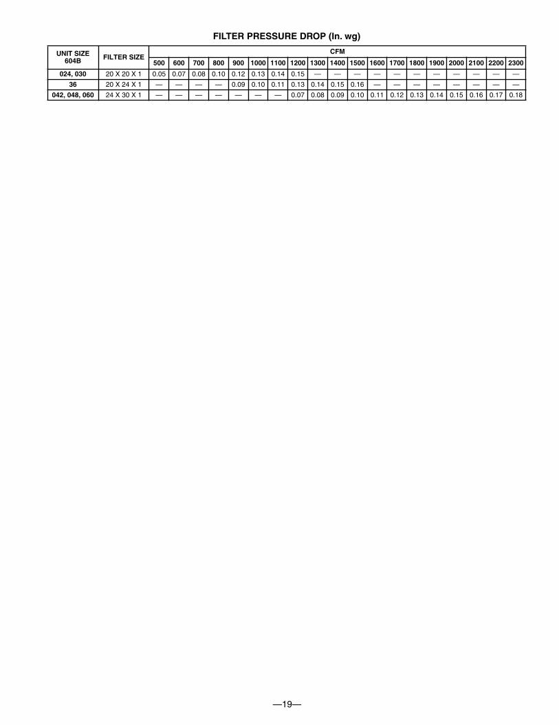
FILTER PRESSURE DROP (In. wg)
UNIT SIZE604B FILTER SIZE
CFM
500 600 700 800 900 1000 1100 1200 1300 1400 1500 1600 1700 1800 1900 2000 2100 2200 2300
024, 030 20 X 20 X 1 0.05 0.07 0.08 0.10 0.12 0.13 0.14 0.15 — — — — — — — — — — —
36 20 X 24 X 1 — — — — 0.09 0.10 0.11 0.13 0.14 0.15 0.16 — — — — — — — —
042, 048, 060 24 X 30 X 1 — — — — — — — 0.07 0.08 0.09 0.10 0.11 0.12 0.13 0.14 0.15 0.16 0.17 0.18

—20—
INDOORTHERMOSTAT
DISCONNECTPER NEC*
FROMPOWERSOURCE
RETURNAIR
TOP COVER
*NEC - NATIONAL ELECTRICAL CODE
TYPICAL PIPING AND WIRING
ROOF
RETURN-AIRFLEXIBLE DUCT
CEILINGCONCENTRIC DIFFUSER BOX(FIELD-SUPPLIED)
SUPPLY-AIRFLEXIBLE DUCT
ROOF-MOUNTINGCURB
C00023
C00063

—21—
Condensate trap — A 2-in. condensate trap must be fieldsupplied.
Ductwork — Secure downflow discharge ductwork to roofcurb. For horizontal discharge applications, attachductwork to unit with flanges.To convert a unit to downflow discharge — Units areequipped with factory-installed inserts in the downflowopenings. Remove the inserts similar to removing an
electrical knock-out. Leave on duct covers to seal thehorizontal discharge openings in the unit. Units installed inhorizontal discharge orientation do not require ductcovers.Maximum cooling airflow — To minimize the possibilityof condensate blow-off from the evaporator, airflowthrough the units should not exceed 450 cfm/ton.Minimum cooling airflow — The minimum airflow is 350cfm/ton for cooling mode. Airflow can be lower in certainmodes when humidity removal is an issue.Minimum cooling ambient operating temperature — Allstandard units have a minimum ambient operatingtemperature of 55°F. With accessory low ambienttemperature kit, units can operate at temperatures down to0°F.Maximum operating outdoor air temperature —Maximum outdoor operating air temperature for cooling is125°F.
APPLICATION DATA
1” MIN.
2” MIN.
TRAPOUTLET
Balance Point Worksheet
0
10
20
30
40
50
60
70
-20 -10 0 10 20 30 40 50 60
Outdoor Air Temp (Deg F)
Build
ing
Heat
Los
s, 1
000B
TUH
Unit
Inte
tgra
ted
Heat
ing
Capa
city,
1000
BTUH
060
048
042
036
030
024
Based on Entering Indoor Air of 70 Deg. F and Rated CFM

—22—
ELECTRICAL DATA
See Legend and Notes on p. 23
UNIT 604BSIZE V-PH-HZ
VOLTAGERANGE
COMPRESSORODFMFLA
IDFMFLA
ELECTRIC HEAT SINGLE POINT POWER SUPPLY
Min Max RLA LRA Nominal kW* FLA UNIT MCA MAX FUSE OR CKT BKR MOCP
024 208/230–1–60 187 253 13.5 61.0 0.9 4.3
-/-3.8/5.05.4/7.27.5/10.0
-/-18.1/20.8
26/3036.1/41.7
22.1/22.144.6/48.154.6/59.667.2/74.2
30/3060/60
——
——
70/7080/80
030 208/230–1–60 187 253 15.9 73.0 0.9 4.3
-/-3.8/5.05.4/7.27.5/10.011.3/15.0
-/-18.1/20.8
26/3036.1/41.754.2/62.5
25.1/25.147.6/51.157.6/62.670.2/77.292.8/103.2
30/30————
—60/7070/8080/90
100/110
036
208/230–1–60 187 253 16.9 83.0 0.9 6.8
-/-3.8/5.05.4/7.27.5/10.011.3/15.0
-/-18.1/20.8
26/3036.1/41.754.2/62.5
28.8/28.851.4/54.961.3/66.374.0/80.996.5/107
35/35————
—70/7080/8090/90
100/110
208/230–3–60 187 253 12.2 77.0 1.6 6.8
-/-3.8/5.07.5/10.011.3/15.0
-/-10.4/12.020.8/24.131.3/36.1
23.7/23.736.7/38.749.7/53.762.7/68.8
30/3050/5060/60
—
———
70/80
042
208/230–1–60 187 253 22.4 105.0 0.9 6.8
-/-3.8/5.05.4/7.27.5/10.011.3/15.015.0/20.0
-/-18.1/20.8
26/3036.1/41.754.2/62.572.2/83.3
35.7/35.758.3/61.768.2/73.280.8/87.8
103.4/113.8126.0/139.9
45/45—————
—80/8090/90
100/100125/125150/150
208/230–3–60 187 253 15.4 88.0 0.9 6.8
-/-3.8/5.07.5/10.011.3/15.015.0/20.0
-/-10.4/12.020.8/24.131.3/36.141.6/48.0
27.0/27.040.0/42.053.0/57.066.0/72.178.9/86.9
35/3560/60
———
——
70/7080/8090/100
048
208/230–1–60 187 253 21.3 109.0 1.6 6.8
-/-3.8/5.05.4/7.27.5/10.011.3/15.015.0/20.0
-/-18.1/20.8
26/3036.1/41.754.2/62.572.2/83.3
35.0/35.057.6/61.167.5/72.580.2/87.1
102.7/113.2125.3/139.2
45/45—————
—80/8090/90
100/100125/125150/150
208/230–3–60 187 253 14.7 91.0 1.6 6.8
-/-3.8/5.07.5/10.011.3/15.015.0/20.0
-/-10.4/12.020.8/24.131.3/36.141.6/48.0
26.8/26.839.8/41.852.8/56.865.9/71.978.7/86.7
35/3560/60
———
——
70/7080/8090/90
060
208/230–1–60 187 253 26.9 145.0 1.5 9.1
-/-3.8/5.05.4/7.27.5/10.011.3/15.015.0/20.0
-/-18.1/20.8
26/3036.1/41.754.2/62.572.2/83.3
44.2/44.266.8/70.376.7/81.789.4/96.3
111.9/122.4134.5/148.4
60/60—————
—90/100100/110110/125150/150150/175
208/230–3–60 187 253 17.6 123.0 1.5 9.1
-/-3.8/5.07.5/10.011.3/15.015.0/20.0
-/-10.4/12.020.8/24.131.3/36.141.6/48.0
32.6/32.658.7/62.758.7/62.771.7/77.784.6/92.6
40/4060/60
———
——
70/7080/8090/90

—23—
228 = 1 v229 = 2 v227 = 2 v
LEGEND
FLA -- Full Load AmpsLRA -- Locked Rotor AmpsMCA -- Minimum Circuit AmpsMOCP -- Maximum Overcurrent ProtectionRLA -- Rated Load Amps
NO TES:1. In compliance with NEC (National Electrical Code) requirements
for multimotor and combination load equipment (refer to NE CArticles 430 and 440), the overcurrent protective device for theunit shall be Power Supply fuse. The CGA (Canadian GasAssociation) units may be fuse or circuit break er.
2. Minimum wire size is based on 60 C copper wire. I f other than60 C wire is used, or if length exceeds wire length in table,determine siz e from NEC..
3. Unbalanced 3-Phase Supply VoltageNever operate a motor where a phase imbalance in supply volt-age is greater than 2%. Use the following formula to determinethe percentage of voltage imbalance.
% Voltage imbalance
max voltage deviation from average voltage= 100 xaverage voltage
EXAMPLE: Supply voltage is 230-3-60.AB = 228 vBC = 231 vAC = 227 v
228 + 231 + 227Average Voltage =3
686=3
= 229
Determine maximum deviation from average voltage.(AB) 229 -(BC) 231 -(AC) 229 -
Maximum deviation is 2 v.
Determine percent of voltage imbalance.2% Voltage Imbalance = 100 x
229
= 0.8%
This amount of phase imbalance is satisfactory as it is below themaximum allowable 2%.
IMPORTANT: If the supply voltage phase imbalance ismore than 2%, contact your local electric utility companyimmediately.
(R)
*Heater capacity (kW) based on heater voltage of 208v & 240v.If power distibution voltage to unit varies from rated heater voltage, heater kW will vary accordingly.

—24—
TYPICAL WIRING SCHEMATIC — 230-1-60 SHOWN

—25—
TYPICAL WIRING SCHEMATIC — 208/230-3-60 SHOWN
1
3
2

—26—
SEQUENCE OF OPERATION
When power is supplied to unit, the transformer (TRAN) isenergized.
On units with crankcase heater, heater is also energized.
Cooling — With the thermostat subbase in the cooling position,the thermostat makes circuit R-O. This energizes the reversingvalve solenoid (RVS) and places the unit in standby condition forcooling.
As the space temperature rises, the thermostat makes, closingcircuit R-Y. A circuit is made to contactor (C), starting thecompressor (COMP) and outdoor-fan motor (OFM). Circuit R-Gis made at the same time, energizing and starting the indoor-fanmotor (IFM).
When the thermostat is satisfied, contacts open, deenergizing C.The COMP and OFM stop, and the IFM stops after a preselectedtime delay.
Heating — On a call for heat, thermostat makes circuits R-Y andR-G.
A circuit is made to C, starting COMP and OFM. Circuit R-G alsois completed, energizing IFR and starting IFM after the selectedtime delay.
Should room temperature continue to fall, circuit R-W is madethrough second-stage thermostat bulb. If optional electric heatpackage is used, a relay is energized, bringing on first bank ofsupplemental electric heat. When thermostat is satisfied,
contacts open, deenergizing contactor and relay; motors andheaters deenergize. The IFM is controlled by the Easy Select™board.
Defrost — Defrost board (DB) is a time and temperature control,which includes a field-selectable time period (Dip switch 1 and 2on the board) between checks for defrost (30, 60, 90, or 120minutes). Electronic timer and defrost cycle start only whencontactor is energized and defrost thermostat (DFT) is closed.
The defrost board is also equipped with a 3rd dip switch forselecting Quiet Shift operation. The Quiet Shift operation turnscompressor off at defrost initiation and termination. Unit isfactory shipped with quiet shift turned off.
Defrost mode is identical to cooling mode, except outdoor fanmotor stops and a bank of optional electric heat turns on to warmair supplying the conditioned space.
NOTES:
1. Compressor time delay occurs through the defrost controlboard.
2. Defrost control board has built in 5 minute compressor delay:once the compressor has started and then stopped, it cannot berestarted again until 5 minutes have elapsed.
3. Variable Speed Blower — The indoor blower operation with acall for fan operation (G) in either cooling or heat pump heating(compressor) modes will perform by the on/off delay profileselected at start up on the Easy Select™ board.
CONTROLS

—27—
PACKAGED HEAT PUMP UNITS CONSTANT VOLUME APPLICATION
HVAC GUIDE SPECIFICATIONSSIZE RANGE: 2 TO 5 TONS, NOMINAL COOLINGBRYANT MODEL NUMBER: 604BPART 1—GENERALSYSTEM DESCRIPTION
Outdoor rooftop or ground mounted, heat pump unit uti-lizing a hermetic compressor for heating and coolingduty and optional electric heating. Unit shall dischargesupply air vertically or horizontally as shown on contractdrawings. Outdoor fan/coil section shall have a draw-thru design with vertical discharge for minimum soundlevels.
QUALITY ASSURANCEA. Unit shall be rated in accordance with ARI Standards 210/
240-94 and 270-95.B. Unit shall be designed in accordance with UL Standard
1995.C. Unit shall be manufactured in a facility registered to ISO
9001 manufacturing quality standard.D. Unit shall be UL listed and c-UL certified as a total package
for safety requirements.E. Roof curb shall be designed to conform to NRCA Stan-
dards.F. Insulation and adhesives shall meet NFPA 90A require-
ments for flame spread and smoke generation.G. Cabinet insulation shall meet ASHRAE Standard 62P.
DELIVERY, STORAGE AND HANDLINGUnit shall be stored and handled per manufacturer’srecommendations.
PART 2 — PRODUCTSEQUIPMENT
A. General:Factory-assembled, single-piece, heat pump unit. Con-tained within the enclosure shall be all factory wiring, pip-ing, controls, refrigerant charge (R-410A), and specialfeatures required prior to field start-up.
B. Unit Cabinet:1. Unit cabinet shall be constructed of phosphated, zinc-
coated, pre-painted steel capable of withstanding 500hrs of salt spray.
2. Normal service shall be through a single removablecabinet panel.
3. The unit shall be constructed on a rust proof unit basethat has an externally trapped, integrated sloped drainpan.
4. Indoor fan compartment top surface shall be insulatedwith a minimum 1/2-in. thick, flexible fiberglass insula-tion, coated on the air side and retained by adhesiveand mechanical means. The indoor wall sections willbe insulated with a minimum semi-rigid foil-faced boardcapable of being wiped clean. Aluminum foil-faced fi-berglass insulation shall be used in the entire indoor aircavity section.
5. Unit shall have a field-supplied condensate trap.
C. Fans:1. The indoor fan shall be variable speed motor and con-
trol, as shown on equipment drawings.2. Fan wheel shall be made from steel, and shall be dou-
ble-inlet type with forward curved blades with corrosionresistant finish. Fan wheel shall be dynamically bal-anced.
3. Outdoor fan shall be direct drive propeller type with alu-minum blades riveted to corrosion resistant steel spi-ders, be dynamically balanced, and discharge airvertically.
D. Compressor:1. Fully hermetic compressors with factory-installed vibra-
tion isolation.2. Scroll compressors shall be standard on all units.3. Compressor Protection:
Defrost control shall protect compressor by preventing“short cycling.”
E. Coils:Indoor and outdoor coils shall have aluminum plate finsmechanically bonded to seamless copper tubes with alljoints brazed. (Copper/copper and vinyl-coated construc-tion available as option.) Tube sheet openings shall bebelled to prevent tube wear.
F. Refrigerant Metering Device:Refrigerant metering device shall be of the single bodyfixed orifice feed type (outdoor) and TXV (indoor).
G. Filters:Filter section shall consist of field-installed, throwaway, 1-in. thick fiberglass filters of commercially available sizes.
H. Controls and Safeties:1. Unit controls shall be complete with a self-contained
low voltage control circuit.2. Units shall incorporate an internal compressor protec-
tor that provides reset capability.3. Unit shall provide High and Low/Loss-of-Charge Pres-
sure Safety Protection.I. Operating Characteristics:
1. Unit shall be capable of starting and running at 125°Fambient outdoor temperature, exceeding maximumload criteria of ARI Standard 240-94.
2. Compressor with standard controls shall be capable ofoperation down to 55° F ambient outdoor temperature incooling and -10°F in heating.
3. Fan on/off delay profile is selected (for compressormodes) on the Easy Select™ board.
J. Electrical Requirements:All unit power wiring shall enter the unit cabinet at a singlelocation.
K. Motors:1. Compressor motors shall be of the refrigerant-cooled
type with line-break thermal and current overload pro-tection.
2. All fan motors shall have permanently lubricated bear-ings, and inherent, automatic reset, thermal overloadprotection.
3. Outdoor fan motor shall be totally enclosed.
GUIDE SPECIFICATIONS

SPECIFICATIONS SUBJECT TO CHANGE WITHOUT NOTICE
UNIT MUST BE INSTALLED IN ACCORDANCEWITH INSTALLATION INSTRUCTIONS
Cancels: PDS 604B.24.1
Form PDS 604B.24.2
© 2004 Bryant Heating & Cooling Systems, 7310 W. Morris St., Indpls., IN 46231 PRINTED IN U.S.A. Catalog No. 5260-401 2-04
—28—
L. Grille1. Louvered Grille:
Louvered grille shall be standard on all units. M. Special Features Available
1. Coil Options:Shall include factory-installed optional tin-plated in-door, copper/copper and vinyl-coated refrigerantcoils.
2. Economizer:a. Economizer controls capable of providing free cool-
ing using outside air.b. Equipped with low leakage dampers not to exceed
3% leakage, at 1.0 in. wg pressure differential.c. Spring return motor shuts off outdoor damper on
power failure.3. Flat Roof Curb:
Curbs shall have seal strip and a wood nailer for flash-ing and shall be installed per manufacturer’s instruc-tions.
4. Manual Outdoor Air Damper:Package shall consist of damper, birdscreen, and rain-hood which can be preset to admit outdoor air for year-round ventilation.
5. Thermostat:To provide for two-stage heating and one-stage coolingin addition manual or automatic changeover and indoorfan control.
6. Low Ambient Package:Shall consist of a solid-state control and outdoor coiltemperature sensor for controlling outdoor fan motoroperation, which shall allow unit to operate down to0° F outdoor ambient temperature in cooling.
7. Filter Rack Kit:Shall provide filter mounting for downflow and horizon-tal applications.
8. Square-To-Round Duct Transitions:Shall have the ability to convert the supply and returnopenings from rectangular to round. (024-048 only)
9. Crankcase Heater:Shall provide anti-floodback protection for low-loadcooling applications. (Standard on 042-060 sizes)
10. Electric heaters:a. Electric heater shall be available as a field-installed
option.b. Heater elements shall be open wire type, adequately
supported and insulated with ceramic bushings.c. Electric heater packages must provide single point
power connection capability.11. Compressor Hard start kit:
Shall be available to give a boost to the compressormotor at each start-up.
GUIDE SPECIFICATIONS (CONT)