single-particle electron microscopy (cryo-electron microscopy) · 2 last month’s nobel prize in...
TRANSCRIPT

Single-particleelectronmicroscopy(cryo-electronmicroscopy)
CS/CME/BioE/Biophys/BMI279Nov.16and28,2017
RonDror
1

2
Last month’s Nobel Prize in Chemistry
Awarded to Jacques Dubochet, Joachim Frank and Richard Henderson and "For developing cryo-electron microscopy for the high-resolution structure determination of biomolecules in solution"

3
Nature,Sept.10,2015

Outline
• Overview of single-particle electron microscopy (EM) • Single-particle EM images are projections • Sample preparation • Computational reconstruction methods
– 2D image analysis • Image preprocessing • Particle picking • Image clustering and class averaging
– 3D reconstruction • Reconstruction with known view angles • Structure refinement with unknown view angles • Calculating an initial structure • Fitting atomic-resolution models to lower-resolution EM
structures 4
Theimagesareverynoisy.First,cleanupthe2Dimages.Thentrytorecreatethe3Dstructurewhoseprojectioncreatedthose2Dimages.

Overview of single-particle electron microscopy (EM)
5

The basic idea• We want the structure of a “particle”: a molecule (e.g., protein) or a well-defined
complex composed of many molecules (e.g., a ribosome) • We spread identical particles out on a film, and image them using an electron
microscope • The images are two-dimensional (2D), and each particle is positioned with a different,
unknown orientation. • Given enough 2D images of particles, we can computationally reconstruct the 3D
shape of the particle
6
ImagefromJoachimFrankhttp://biomachina.org/courses/structures/091.pdf
Electronbeam
Particles
Images
7
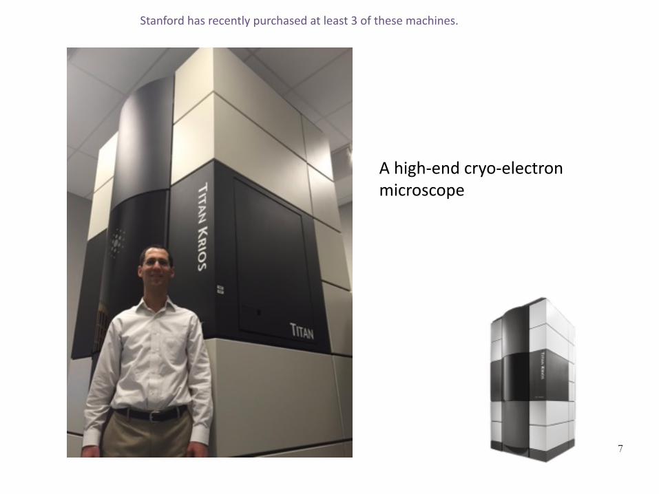
Ahigh-endcryo-electronmicroscope
Stanfordhasrecentlypurchasedatleast3ofthesemachines.

Dramatic recent improvements• Single-particle EM has been around for decades,
but it has improved dramatically in the last five years due to: – Invention of better cameras
• Until recently, electrons were detected either by photographic film, or by scintillator-based digital cameras which converted electrons to photons for detection
• New “direct-electron detectors” can detect electrons directly, substantially improving image resolution and quality
– Better computational reconstruction techniques • Single-particle EM is thus coming into much wider
use, and may challenge crystallography as the dominant way to determine experimental structures
8
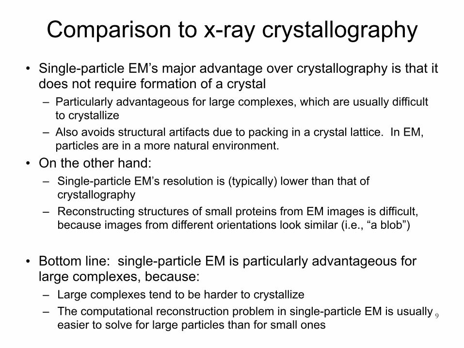
Comparison to x-ray crystallography• Single-particle EM’s major advantage over crystallography is that it
does not require formation of a crystal – Particularly advantageous for large complexes, which are usually difficult
to crystallize – Also avoids structural artifacts due to packing in a crystal lattice. In EM,
particles are in a more natural environment. • On the other hand:
– Single-particle EM’s resolution is (typically) lower than that of crystallography
– Reconstructing structures of small proteins from EM images is difficult, because images from different orientations look similar (i.e., “a blob”)
• Bottom line: single-particle EM is particularly advantageous for large complexes, because: – Large complexes tend to be harder to crystallize – The computational reconstruction problem in single-particle EM is usually
easier to solve for large particles than for small ones9
Single-particle EM images are projections
10

Single-particle EM uses transmission electron microscopy
11http://www.cas.miamioh.edu/~meicenrd/ANATOMY/Ch2_Ultrastructure/Tempcell.htm
Transmissionelectronmicroscopy
http://www.newscientist.com/data/images/ns/cms/dn14136/dn14136-1_788.jpg
Scanningelectronmicrosopy
• In transmission electron microscopy, a beam of electrons pass through a thin sample before forming an image
Scanningelectronmicroscopydetectssurfaces,soitmorecloselymimicshowwenormallysee.

Single-particle EM images are projections
• Each recorded 2D image is thus a projection of the 3D shape (density) we want to reconstruct – That is, we can think of each pixel value in the 2D
image as a sum of the values along a line through the 3D sample (in the direction of the electron beam)
12
Electronbeam
Particles
Images
Likelihoodofparticlebeingstoppedisproportionaltodensityofthecrosssection
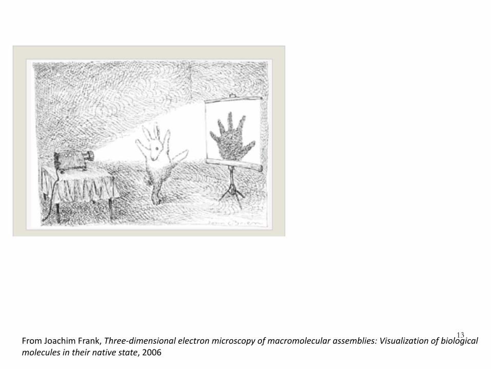
13FromJoachimFrank,Three-dimensionalelectronmicroscopyofmacromolecularassemblies:Visualizationofbiologicalmoleculesintheirnativestate,2006
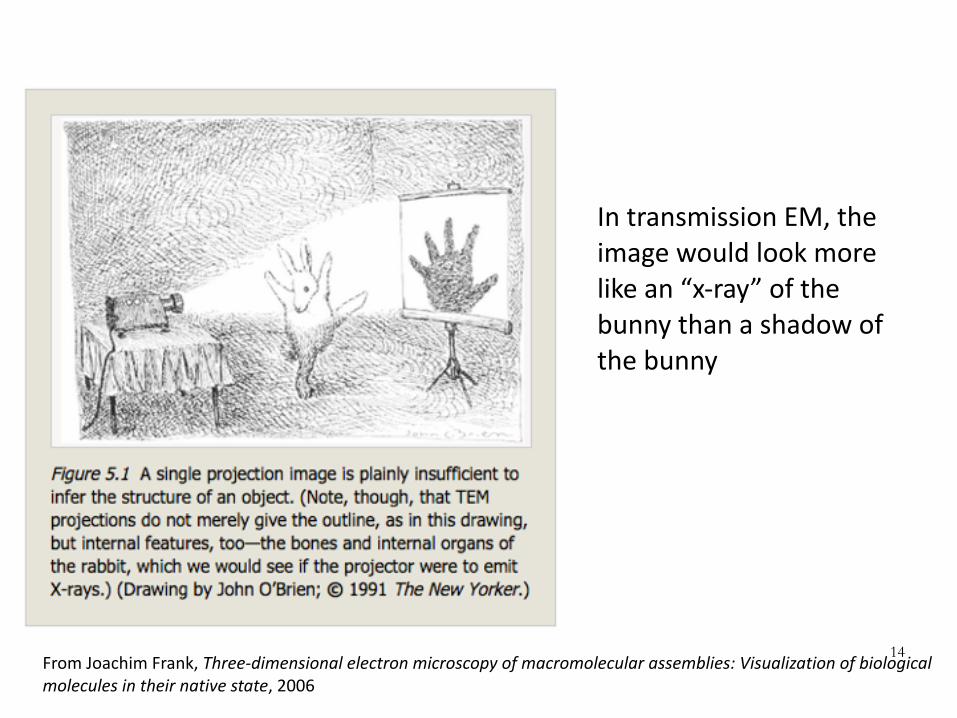
14FromJoachimFrank,Three-dimensionalelectronmicroscopyofmacromolecularassemblies:Visualizationofbiologicalmoleculesintheirnativestate,2006
IntransmissionEM,theimagewouldlookmorelikean“x-ray”ofthebunnythanashadowofthebunny

Sample preparation
15
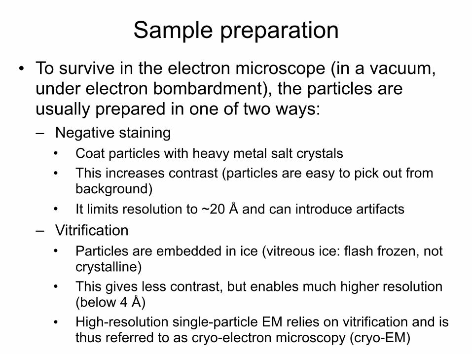
Sample preparation• To survive in the electron microscope (in a vacuum,
under electron bombardment), the particles are usually prepared in one of two ways: – Negative staining
• Coat particles with heavy metal salt crystals • This increases contrast (particles are easy to pick out from
background) • It limits resolution to ~20 Å and can introduce artifacts
– Vitrification • Particles are embedded in ice (vitreous ice: flash frozen, not
crystalline) • This gives less contrast, but enables much higher resolution
(below 4 Å) • High-resolution single-particle EM relies on vitrification and is
thus referred to as cryo-electron microscopy (cryo-EM)
17
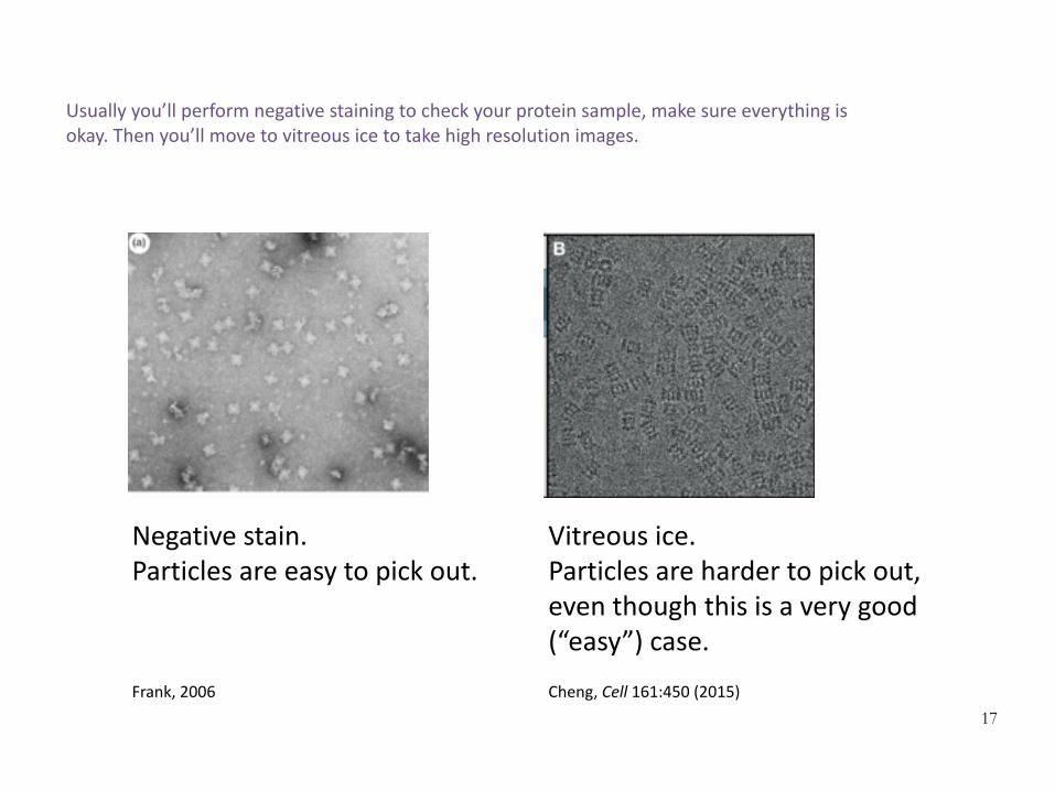
Negativestain.Particlesareeasytopickout.
Vitreousice.Particlesarehardertopickout,eventhoughthisisaverygood(“easy”)case.
Frank,2006 Cheng,Cell161:450(2015)
Usuallyyou’llperformnegativestainingtocheckyourproteinsample,makesureeverythingisokay.Thenyou’llmovetovitreousicetotakehighresolutionimages.

Computational reconstruction methods
18

Overview of computational methods
• 2D image analysis: First, go from raw image data to higher-resolution 2D projections – Image preprocessing – Particle picking – Image clustering and class averaging
• 3D reconstruction: Then use these higher-resolution projections to build a 3D model – Background: Reconstruction with known view angles – Structure refinement with unknown view angles – Calculating an initial structure – Fitting atomic-resolution models to lower-resolution
EM structures 19

Overview of computational methods
20
Chengetal.,Cell161:438(2015)
Thisisagoodreview,checkitout!

Computational reconstruction methods
21
2D image analysis

The raw images don’t look so good
22
Beforeattemptingany3Dreconstruction,wedoseveraltypesofprocessingontheimages
ImagefromJoachimFrankhttp://biomachina.org/courses/structures/091.pdf
Particlesareverylowcontrast,meaningtheydon’tstandoutverywellfromthebackground.Actually,thisisanespeciallycleanexample!

Computational reconstruction methods
23
2D image analysis
Image preprocessing

Image preprocessing
• Problem 1: The sample tends to move slightly during imaging, blurring the image
• Solution – Direct electron detectors are fast enough to record a
movie instead of a single image – Align the movie frames computationally, then average
them together
24
Itwasn’tuntilrecentlythatdetectorswerefastenoughtorecordamovie.
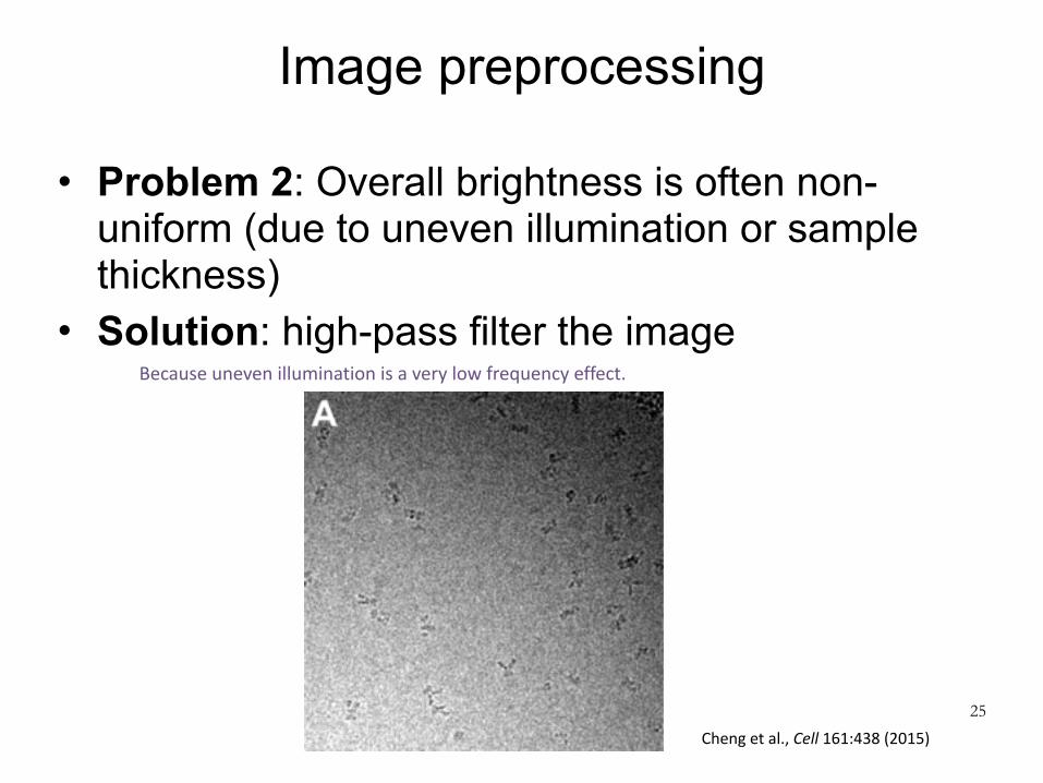
Image preprocessing
• Problem 2: Overall brightness is often non-uniform (due to uneven illumination or sample thickness)
• Solution: high-pass filter the image
25
Chengetal.,Cell161:438(2015)
Becauseunevenilluminationisaverylowfrequencyeffect.
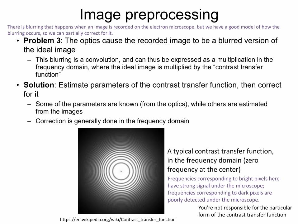
Image preprocessing• Problem 3: The optics cause the recorded image to be a blurred version of
the ideal image – This blurring is a convolution, and can thus be expressed as a multiplication in the
frequency domain, where the ideal image is multiplied by the “contrast transfer function”
• Solution: Estimate parameters of the contrast transfer function, then correct for it
– Some of the parameters are known (from the optics), while others are estimated from the images
– Correction is generally done in the frequency domain
Atypicalcontrasttransferfunction,inthefrequencydomain(zerofrequencyatthecenter)
You’renotresponsiblefortheparticularformofthecontrasttransferfunction
https://en.wikipedia.org/wiki/Contrast_transfer_function
Frequenciescorrespondingtobrightpixelsherehavestrongsignalunderthemicroscope;frequenciescorrespondingtodarkpixelsarepoorlydetectedunderthemicroscope.
Thereisblurringthathappenswhenanimageisrecordedontheelectronmicroscope,butwehaveagoodmodelofhowtheblurringoccurs,sowecanpartiallycorrectforit.

Computational reconstruction methods
27
2D image analysis
Particle picking
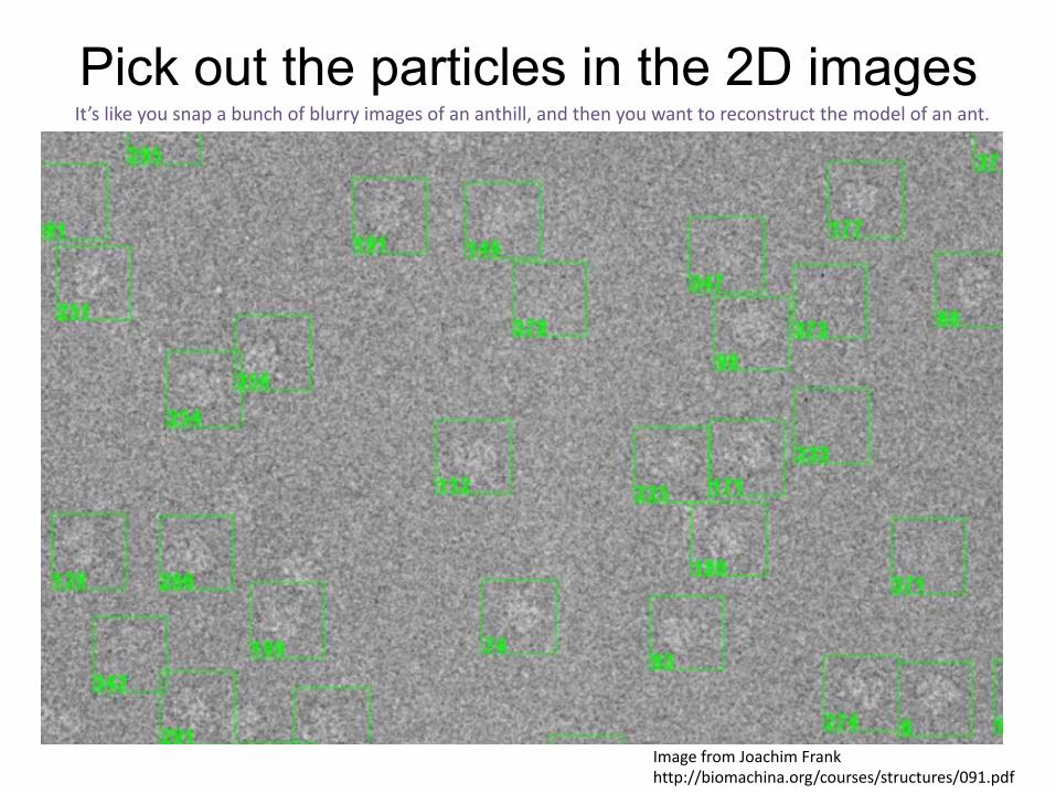
Pick out the particles in the 2D images
28
ImagefromJoachimFrankhttp://biomachina.org/courses/structures/091.pdf
It’slikeyousnapabunchofblurryimagesofananthill,andthenyouwanttoreconstructthemodelofanant.
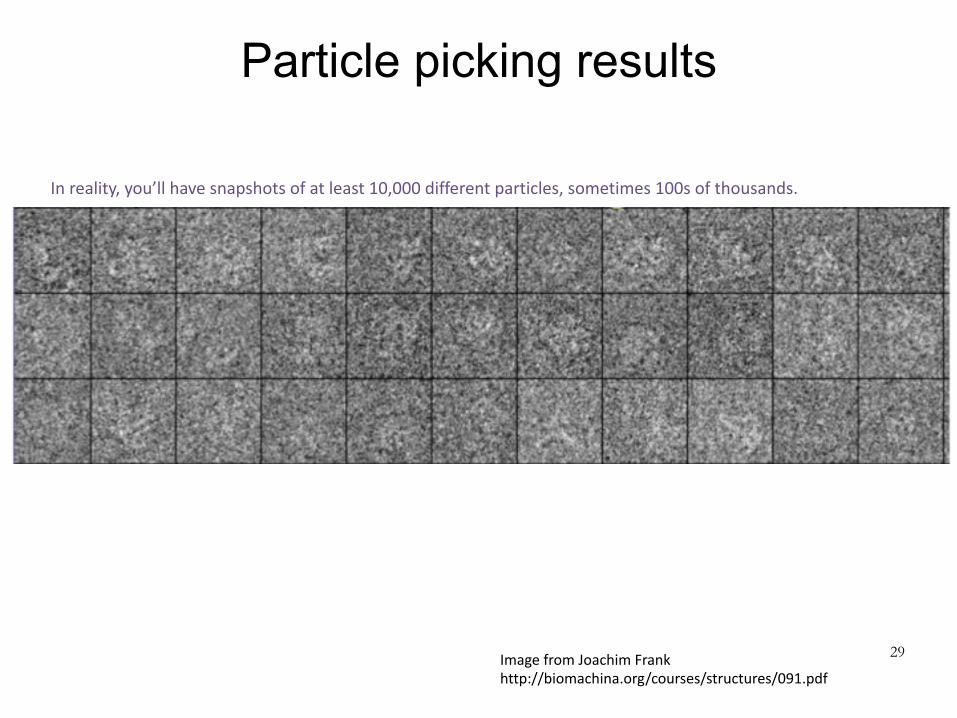
Particle picking results
29ImagefromJoachimFrankhttp://biomachina.org/courses/structures/091.pdf
Inreality,you’llhavesnapshotsofatleast10,000differentparticles,sometimes100softhousands.

Particle picking methods
• Particle picking can be difficult, because the images are low-contrast and noisy – Images may also have
contaminants that should be ignored
• A variety of automated and semi-automated methods have been developed – For example, matching to
templates, or picking out high-contrast regions
• Often this is still done manually, at least to seed automated methods with suitable templates
30
Chengetal.,Cell2015
ParticleofinterestContaminant
Doingamanualannotationhelpsyoumakesureyourdatalookokay.Thisalsoprovidestemplatesthatteachesthesoftwarewhataparticleshouldroughlylooklike.
Computational reconstruction methods
31
2D image analysis
Image clustering and class averaging
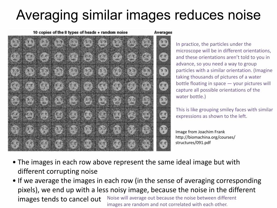
• Theimagesineachrowaboverepresentthesameidealimagebutwithdifferentcorruptingnoise
• Ifweaveragetheimagesineachrow(inthesenseofaveragingcorrespondingpixels),weendupwithalessnoisyimage,becausethenoiseinthedifferentimagestendstocancelout
Averaging similar images reduces noise
ImagefromJoachimFrankhttp://biomachina.org/courses/structures/091.pdf
Noisewillaverageoutbecausethenoisebetweendifferentimagesarerandomandnotcorrelatedwitheachother.
Inpractice,theparticlesunderthemicroscopewillbeindifferentorientations,andtheseorientationsaren’ttoldtoyouinadvance,soyouneedawaytogroupparticleswithasimilarorientation.(Imaginetakingthousandsofpicturesofawaterbottlefloatinginspace—yourpictureswillcaptureallpossibleorientationsofthewaterbottle.)
Thisislikegroupingsmileyfaceswithsimilarexpressionsasshowntotheleft.

Goal: cluster the particle images into classes of similar images
• Group together images with similar view angles – Then align them to one another and average them
together to reduce noise • To do this, divide images into several classes (with
each class representing a set of similar view angles) • We need to determine both what the classes are
and which images should be assigned to each class • This is a clustering problem
– Group images such that the images within a group are similar, but images in different groups are different
– In machine learning terminology, this is “unsupervised learning” 33

Standard approach: k-means clustering
• Pick k random images as class exemplars • Then iterate the following:
– Assign each image to the closest exemplar – Average all the images in each class to determine a new class exemplar
34
kisdecidedinadvance.
Ontheleftisanexampleofk-meansclusteringiterationfromhttp://stanford.edu/~cpiech/cs221/handouts/kmeans.html,whichalsogivesagoodmathematicalexplanation.

Standard approach: k-means clustering
• Pick k random images as class exemplars • Then iterate the following:
– Assign each image to the closest exemplar – Average all the images in each class to determine a new class exemplar
• Notes: – In the assignment step, we need to align each particle image against
the exemplar images – We need to specify the number of classes (k) in advance, or experiment
with different values of k – k-means clustering is guaranteed to converge, but not guaranteed to
find a globally optimal solution – Indeed, the solution may depend heavily on the initialization conditions,
and may be heavily suboptimal
35
kisdecidedinadvance.

Caveat: Potential model bias in clustering/alignment
36
ImagefromSteveLudtkehttp://biomachina.org/courses/structures/091.pdf
In this case, the images are just noise, but by selecting images and alignments that best match a given template, we get a class average that looks like the template.
Numberofalignedandaveragedimages
Thisisessentiallybecausethealignmentstepbiasestherandompixelstowardspositionsthatmatchthetemplateimageofthelittlegirl,sowhentheseimagesareaveragedyoureproducetheimageofthelittlegirl.
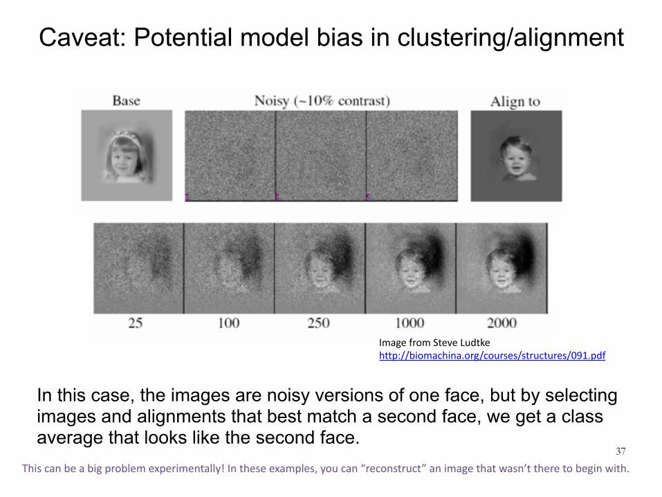
Caveat: Potential model bias in clustering/alignment
37
ImagefromSteveLudtkehttp://biomachina.org/courses/structures/091.pdf
In this case, the images are noisy versions of one face, but by selecting images and alignments that best match a second face, we get a class average that looks like the second face.
Thiscanbeabigproblemexperimentally!Intheseexamples,youcan“reconstruct”animagethatwasn’ttheretobeginwith.
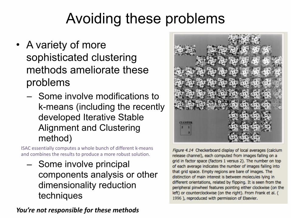
Avoiding these problems
• A variety of more sophisticated clustering methods ameliorate these problems – Some involve modifications to
k-means (including the recently developed Iterative Stable Alignment and Clustering method)
– Some involve principal components analysis or other dimensionality reduction techniques 38
You’renotresponsibleforthesemethods
ISACessentiallycomputesawholebunchofdifferentk-meansandcombinestheresultstoproduceamorerobustsolution.

Class averaging results
These are considered good class averages (from a high-resolution single-particle EM study)
39
Cheng,Cell161:450(2015)
Computational reconstruction methods
40
3D reconstruction

Problem
• Working with your neighbor, try to come up with one way to do it if you know the view angle for each projection, and another if you don’t – Don’t look at the next few slides. If you already have,
try to come up with approaches that are not on those slides. 41
Originalimage
Projections
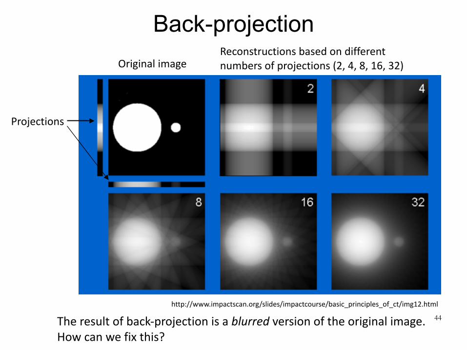
• Suppose you’re given many projections of a 2D image, and you want to reconstruct the original image. How would you do it?
Projectionsarethesumalongtheverticalorhorizontalline

Computational reconstruction methods
42
3D reconstruction
Background: Reconstruction with known view angles

Suppose you knew the view angle for each particle image
• How would you reconstruct the 3D density map from 2D projections? – Same problem is encountered in medical imaging
(e.g. in CT scans, which are basically 3D x-rays) • The simplest approach would be back-projection:
reverse the projection process by “smearing” each projection back across the reconstructed image
43
Back-projection
44
http://www.impactscan.org/slides/impactcourse/basic_principles_of_ct/img12.html
Originalimage
Projections
Reconstructionsbasedondifferentnumbersofprojections(2,4,8,16,32)
Theresultofback-projectionisablurredversionoftheoriginalimage.Howcanwefixthis?

Filtered-back projection• It turns out we can fix this problem by applying a
specific high-pass filter to each image before back-projection. This is filtered back-projection.
45
http://www.impactscan.org/slides/impactcourse/basic_principles_of_ct/img15.gif

Why does filtered back-projection work?
• To answer this, use the projection slice theorem
46
Projectionslicetheorem(2Dversion):The1DFouriertransformofthe1Dprojectionofa2Ddensityisequaltothecentralsection—perpendiculartothedirectionofprojection—ofthe2DFouriertransformofthedensity
Thistheoremholdsbecauseeachofthe2Dsinusoidsusedinthe2DFouriertransformisconstantinonedirection
You’renotresponsibleforthis
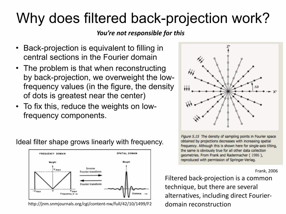
Filteredback-projectionisacommontechnique,butthereareseveralalternatives,includingdirectFourier-domainreconstruction
Why does filtered back-projection work?
• Back-projection is equivalent to filling in central sections in the Fourier domain
• The problem is that when reconstructing by back-projection, we overweight the low-frequency values (in the figure, the density of dots is greatest near the center)
• To fix this, reduce the weights on low-frequency components.
Frank,2006
You’renotresponsibleforthis
http://jnm.snmjournals.org/cgi/content-nw/full/42/10/1499/F2
Ideal filter shape grows linearly with frequency.

This carries over to the 3D case
48Frank,2006
Projectionslicetheorem(3Dversion):The2DFouriertransformofthe2Dprojectionofa3Ddensityisequaltothecentralsection—perpendiculartothedirectionofprojection—ofthe3DFouriertransformofthedensity
You’renotresponsibleforthis
Computational reconstruction methods
49
3D reconstruction
Structure refinement with unknown view angles

Refining a structure
• If we’re not given the view angles for each particle, but we have a decent initial 3D model, then iterate the following steps to improve the model: – For each projection (i.e., each class average), find the
view angle that best matches the 3D model – Given the newly estimated view angles, reconstruct a
better 3D model (e.g., using filtered back-projection) • This is called 3D projection matching
50

An example
51
ImagefromSteveLudtkehttp://biomachina.org/courses/structures/091.pdf
Classaverages(startingpointforreconstruction)
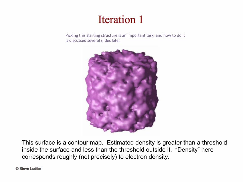
This surface is a contour map. Estimated density is greater than a threshold inside the surface and less than the threshold outside it. “Density” here corresponds roughly (not precisely) to electron density.
Pickingthisstartingstructureisanimportanttask,andhowtodoitisdiscussedseveralslideslater.

Thefirstiterationwasbasedonamodelsoithadsomedetail,butthedetailwasslightlywrong,soiteration2looksmore“blobby”


Final reconstruction
Protein:GroEL6.5Åresolution
Ignorethecolorcoding

A high-resolution single-particle EM structure
57
Lietal.,NatureMethods10:584(2013)A3.3ÅresolutionEMstructure
Youcanseealphahelixes!Andyoucanseeelectrondensitiescorrespondingtoeachside-chain.ThebestEMstructuresarestillnotashigh-resolutionasthebestcrystalstructures,butit’sremarkablethatyoucanachieveatomic-resolutionstructureswiththisapproach.
Caveat
• Structure refinement methods are prone to overfitting – Converged model can show features that don’t really
exist and just reflect noise in the images (analogous to the issue with image clustering)
– A variety of methods have been developed recently to deal with this issue • Some use Bayesian approaches (e.g., RELION
software) • Some of the most important recent algorithmic
developments in single-particle EM are in this area. • You’re not responsible for these methods.
58

Computational reconstruction methods
59
3D reconstruction
Calculating an initial structure
How do we get an initial structural model?
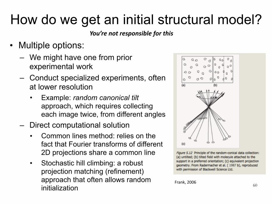
• Multiple options: – We might have one from prior
experimental work – Conduct specialized experiments, often
at lower resolution • Example: random canonical tilt
approach, which requires collecting each image twice, from different angles
– Direct computational solution • Common lines method: relies on the
fact that Fourier transforms of different 2D projections share a common line
• Stochastic hill climbing: a robust projection matching (refinement) approach that often allows random initialization 60
You’renotresponsibleforthis
Frank,2006

Computational reconstruction methods
61
3D reconstruction
Fitting atomic-resolution models to lower-resolution EM structure

Obtaining atomic-resolution models from lower-resolution EM
• Often we have high-resolution x-ray crystallography structures of each individual protein in a complex whose low-resolution structure was determined by single-particle EM.
• We can fit the high-resolution structures into the EM density.
62
Schuretal.,Nature517:505(2015)
Obtaining atomic-resolution models from lower-resolution EM
• Approaches based on molecular dynamics simulations can be used to allow the proteins to relax away from their crystallographic structures to better fit the EM density.
63
https://www.youtube.com/watch?v=6Knykqcxzfg