single-phase control and signalling transformer 36/37/38 ... · 6. electrical characteristics 6....
TRANSCRIPT
87045 LIMOGES CedexTelephone : + 33 05 55 06 87 87 - Fax : + 33 05 55 06 88 88
CONTENTS
1. Operating principle . . . . . . . . . . . . . . . .12. General characteristics. . . . . . . . . . . 1-23. Range. . . . . . . . . . . . . . . . . . . . . . . . . .24. Mechanical characteristics . . . . . . . . 2-35. Determination of transformer power. . .36. Electrical characteristics. . . . . . . . . . 3-47. Others characteristics. . . . . . . . . . . . . .5
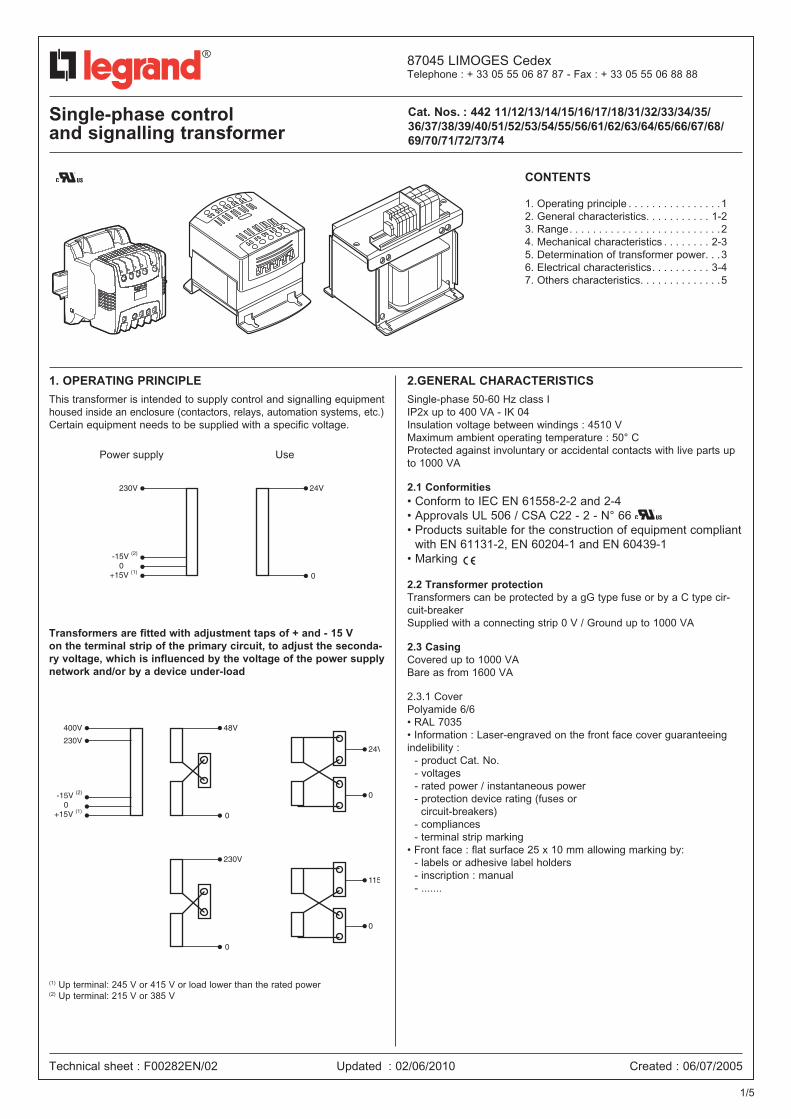
1. OpEraTiNg priNCiplE This transformer is intended to supply control and signalling equipment housed inside an enclosure (contactors, relays, automation systems, etc.)Certain equipment needs to be supplied with a specific voltage.
Transformers are fitted with adjustment taps of + and - 15 V on the terminal strip of the primary circuit, to adjust the seconda-ry voltage, which is influenced by the voltage of the power supply network and/or by a device under-load
(1) Up terminal: 245 V or 415 V or load lower than the rated power(2) Up terminal: 215 V or 385 V
2.gENEral CharaCTEriSTiCS
Single-phase 50-60 Hz class IIP2x up to 400 VA - IK 04Insulation voltage between windings : 4510 VMaximum ambient operating temperature : 50° CProtected against involuntary or accidental contacts with live parts up to 1000 VA
2.1 Conformities• Conform to IEC EN 61558-2-2 and 2-4• Approvals UL 506 / CSA C22 - 2 - N° 66 • Products suitable for the construction of equipment compliant
with EN 61131-2, EN 60204-1 and EN 60439-1• Marking
2.2 Transformer protectionTransformers can be protected by a gG type fuse or by a C type cir-cuit-breakerSupplied with a connecting strip 0 V / Ground up to 1000 VA
2.3 CasingCovered up to 1000 VABare as from 1600 VA
2.3.1 CoverPolyamide 6/6• RAL 7035• Information : Laser-engraved on the front face cover guaranteeingindelibility : - product Cat. No. - voltages - rated power / instantaneous power - protection device rating (fuses or circuit-breakers) - compliances - terminal strip marking• Front face : flat surface 25 x 10 mm allowing marking by: - labels or adhesive label holders - inscription : manual - .......
Technical sheet : F00282EN/02
Cat. Nos. : 442 11/12/13/14/15/16/17/18/31/32/33/34/35/36/37/38/39/40/51/52/53/54/55/56/61/62/63/64/65/66/67/68/ 69/70/71/72/73/74
Updated : 02/06/2010 Created : 06/07/2005
Single-phase control and signalling transformer
0
400V 48V
24V
0
230V
0
230V
115V
0
0-15V (2)
+15V (1)
0
230V 24V
0-15V (2)
+15V (1)
Power supply Use
1/5
Cat. Nos. : 442 11/12/13/14/15/16/17/18/31/32/33/34/35/36/37/38/39/40/51/52/53/54/55/56/61/62/63/64/65/66/67/68/ 69/70/71/72/73/74
Single-phase control and signalling transformer
2. gENEral CharaCTEriSTiCS (continued)
2.3 Casing (continued)
2.3.2 base 40 to 400 VA, polyamide 6/6, glass-filled, flame-retardantfixing by screws or clips up to 250 VA on rail 3400 VA fixing by screw only• 630 to 1000 VA metal base with epoxy-polyester coating RAL 7000• 1600 to 8000 VA : Metal base with anti-corrosion coating
2.3.3 Circuit in silicon magnetic steel sheet- Coating : matte black paint as from 630 VA
2.3.4 Connection terminal strip• 40 VA to 400 VA and 630 VA (115/230) : terminal fitted with a cable clamp plate with slotted cross-head type
Z screw• from 630 VA (ELV) to 1000 VA : Cage terminals with slotted cross-head type Z screw • 1600 to 8000 VA : connection to Viking terminal block
3. raNgEPrimary 230 V ±15 V, 230/400 V ±15 VSecondary 24 V - 24/48 V - 115/230 V
Interference filtering (except 44216/17/18)
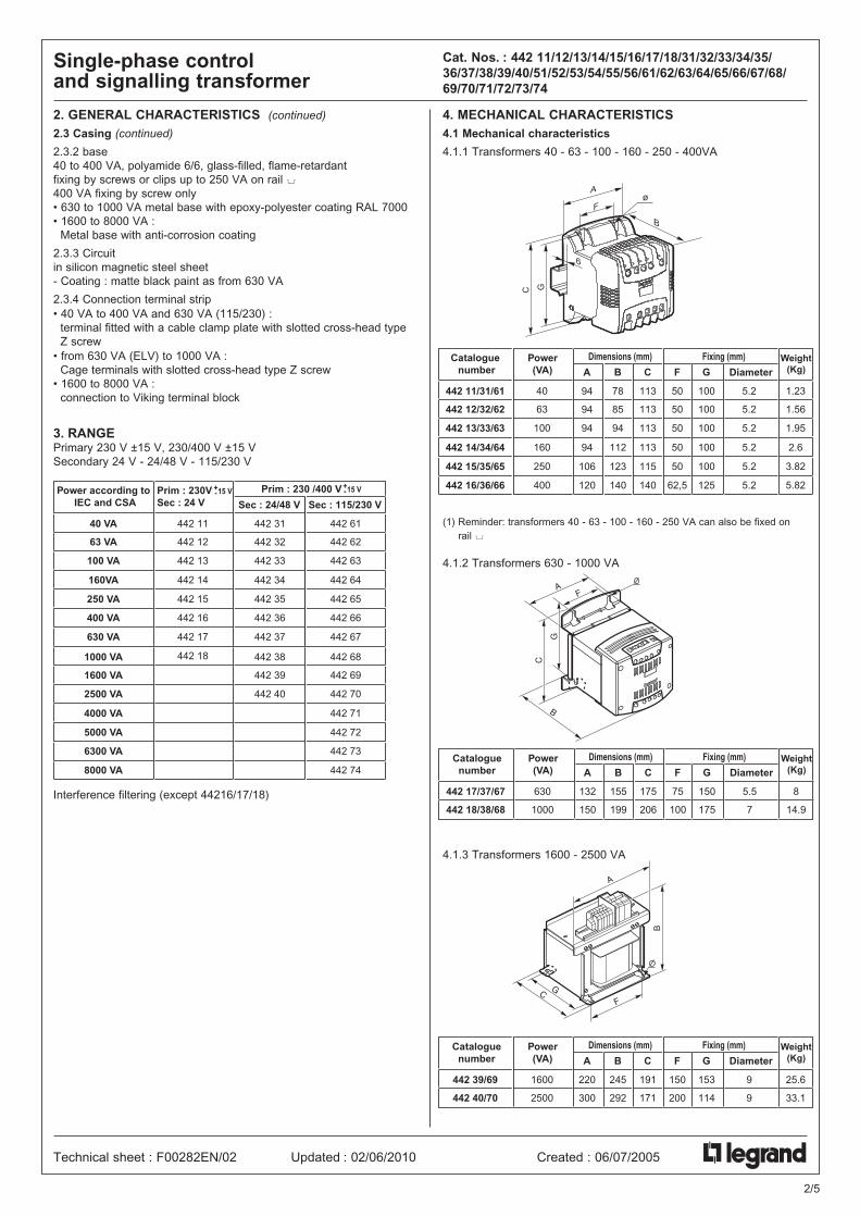
4. MEChaNiCal CharaCTEriSTiCS4.1 Mechanical characteristics
4.1.1 Transformers 40 - 63 - 100 - 160 - 250 - 400VA
(1) Reminder: transformers 40 - 63 - 100 - 160 - 250 VA can also be fixed on rail 3
4.1.2 Transformers 630 - 1000 VA
4.1.3 Transformers 1600 - 2500 VA
Prim : 230VSec : 24 V
Prim : 230 /400 V
Sec : 24/48 V Sec : 115/230 V
40 VA
63 VA
100 VA
160VA
250 VA
400 VA
630 VA
1000 VA
1600 VA
2500 VA
4000 VA
5000 VA
6300 VA
8000 VA
442 31
442 32
442 33
442 34
442 35
442 36
442 37
442 38
442 39
442 40
442 61
442 62
442 63
442 64
442 65
442 66
442 67
442 68
442 69
442 70
442 71
442 72
442 73
442 74
442 11
442 12
442 13
442 14
442 15
442 16
442 17
442 18
Power according to IEC and CSA
+-15 V
+-15 V
A
F
B
6
C G
ø
Power(VA)
Weight(Kg)
Dimensions (mm) Fixing (mm)
A Diameter
442 11/31/61
442 12/32/62
442 13/33/63
442 14/34/64
442 15/35/65
442 16/36/66
94
94
94
94
106
120
B
78
85
94
112
123
140
C
113
113
113
113
115
140
F
50
50
50
50
50
62,5
G
100
100
100
100
100
125
5.2
5.2
5.2
5.2
5.2
5.2
1.23
1.56
1.95
2.6
3.82
5.82
40
63
100
160
250
400
Catalogue number
fc042301d
B
A
C
G
F
Power (VA)
Weight(Kg)
Dimensions (mm) Fixing (mm)
A Diameter
442 17/37/67
442 18/38/68
132
150
B
155
199
C
175
206
F
75
100
G
150
175
5.5
7
8
14.9
630
1000
Catalogue number
F
GC
A
B
Power(VA)
Weight(Kg)
Dimensions (mm) Fixing (mm)
A Diameter
442 39/69
442 40/70
220
300
B
245
292
C
191
171
F
150
200
G
153
114
9
9
25.6
33.1
1600
2500
Cataloguenumber
2/5
Technical sheet : F00282EN/02 Updated : 02/06/2010 Created : 06/07/2005
Cat. Nos. : 442 11/12/13/14/15/16/17/18/31/32/33/34/35/36/37/38/39/40/51/52/53/54/55/56/61/62/63/64/65/66/67/68/ 69/70/71/72/73/74
Single-phase control and signalling transformer
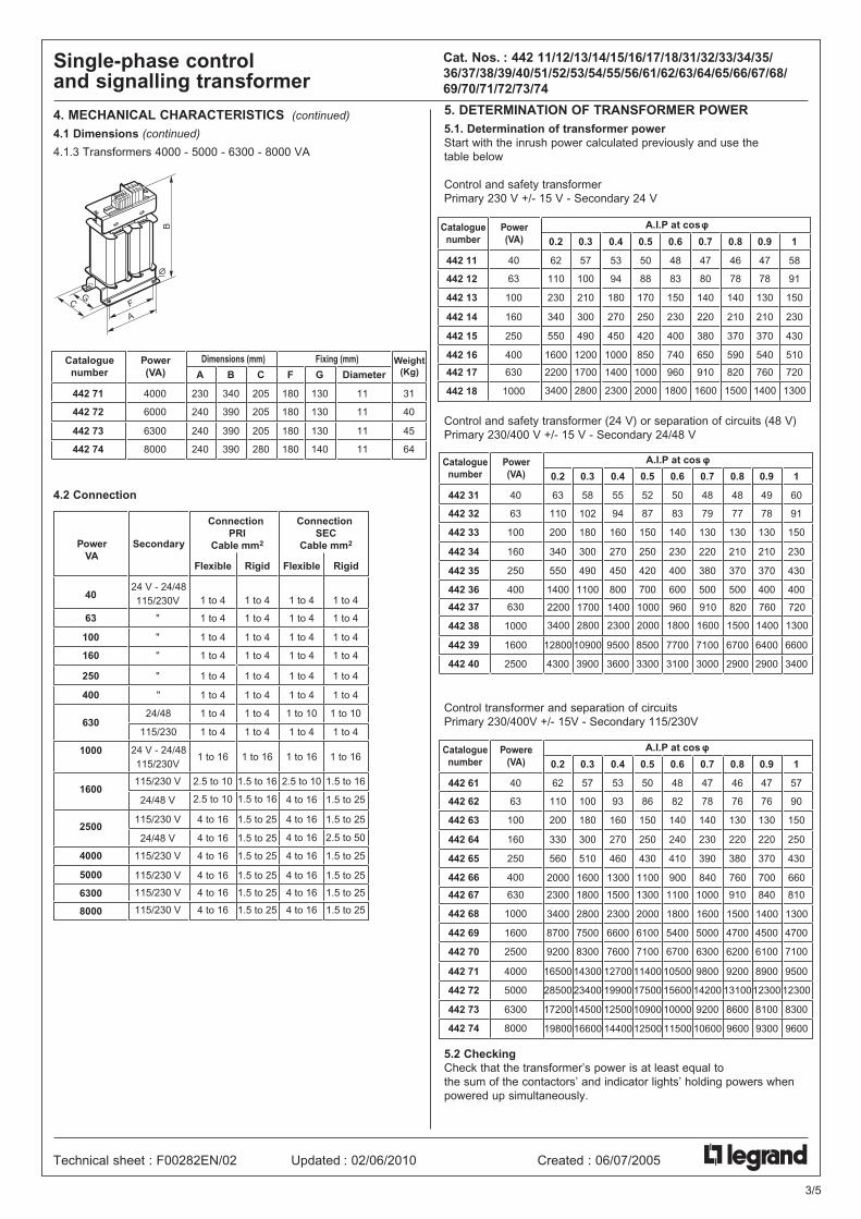
4. MEChaNiCal CharaCTEriSTiCS (continued)
4.1 Dimensions (continued)
4.1.3 Transformers 4000 - 5000 - 6300 - 8000 VA
4.2 Connection
B
F
A
GC
Power(VA)
Weight(Kg)
Dimensions (mm) Fixing (mm)
A Diameter
442 71
442 72
230
240
B
340
390
C
205
205
F
180
180
G
130
130
11
11
31
40
4000
6000
442 73
442 74
240
240
390
390
205
280
180
180
130
140
11
11
45
64
6300
8000
Cataloguenumber
Secondary
Connection PRI
Cable mm2
40
63 1 to 4
Flexible Rigid
Connection SEC
Cable mm2
Flexible Rigid
24 V - 24/48 115/230V
24 V - 24/48115/230V
"
100
160
1 to 4
1 to 4
1 to 4
"
"
250 1 to 4 "
400
630
1 to 4
1 to 4
"
24/48
10001 to 16
1 to 4
1 to 4
1 to 4
1 to 4
1 to 4
1 to 4
1 to 4
1 to 16
1 to 4
1 to 4
1 to 4
1 to 4
1 to 4
1 to 4
1 to 10
1 to 16
1 to 4
1 to 4
1 to 4
1 to 4
1 to 4
1 to 4
1 to 10
1 to 4115/230 1 to 4 1 to 4 1 to 4
1 to 16
16002.5 to 10115/230 V
24/48 V
2500
1.5 to 16
2.5 to 10 1.5 to 16
1.5 to 25
2.5 to 10
4 to 16
4 to 16
1.5 to 16
1.5 to 25
4 to 16115/230 V
24/48 V
1.5 to 25
4 to 16 1.5 to 25
4 to 16
4 to 16
1.5 to 25
2.5 to 50
1.5 to 254000 4 to 16115/230 V
1.5 to 25 4 to 16 1.5 to 254 to 16115/230 V
1.5 to 25 4 to 16 1.5 to 254 to 16115/230 V
1.5 to 25 4 to 16 1.5 to 254 to 16115/230 V
5000
6300
8000
Power VA
3/5
Technical sheet : F00282EN/02 Updated : 02/06/2010 Created : 06/07/2005
5. DETErMiNaTiON Of TraNSfOrMEr pOwEr5.1. Determination of transformer powerStart with the inrush power calculated previously and use the table below
Control and safety transformerPrimary 230 V +/- 15 V - Secondary 24 V
Control and safety transformer (24 V) or separation of circuits (48 V)Primary 230/400 V +/- 15 V - Secondary 24/48 V
Control transformer and separation of circuitsPrimary 230/400V +/- 15V - Secondary 115/230V
5.2 CheckingCheck that the transformer’s power is at least equal to the sum of the contactors’ and indicator lights’ holding powers when powered up simultaneously.
1
58
91
150
230
430
510
720
0.2
62
110
230
340
550
1600
2200
0.3
57
100
210
300
490
1200
1700
0.4
53
94
180
270
450
1000
1400
0.5
50
88
170
250
420
850
1000
0.6
48
83
150
230
400
740
960
0.7
47
80
140
220
380
650
910
0.8
46
78
140
210
370
590
820
0.9
47
78
130
210
370
540
760
Power (VA)
40
63
100
160
250
400
630
1000
442 11
442 12
442 13
442 14
442 15
442 16
442 17
442 18
Catalogue number
A.I.P at cos
13003400 2800 2300 2000 1800 1600 1500 1400
1
60
91
150
230
430
400
0.2
63
110
200
340
550
1400
0.3
58
102
180
300
490
1100
0.4
55
94
160
270
450
800
0.5
52
87
150
250
420
700
0.6
50
83
140
230
400
600
0.7
48
79
130
220
380
500
0.8
48
77
130
210
370
500
0.9
49
78
130
210
370
400
Power (VA)
40
63
100
160
250
400
630
1000
442 31
442 32
442 33
442 34
442 35
442 36
442 37
442 38
6600
3400
12800
4300
10900
3900
9500
3600
8500
3300
7700
3100
7100
3000
6700
2900
6400
2900
1600
2500
442 39
442 40
Catalogue number
7202200 1700 1400 1000 960 910 820 760
A.I.P at cos
13003400 2800 2300 2000 1800 1600 1500 1400
1
57
90
150
250
430
810
0.2
62
110
200
330
560
2300
0.3
57
100
180
300
510
1800
0.4
53
93
160
270
460
1500
0.5
50
86
150
250
430
1300
0.6
48
82
140
240
410
1100
0.7
47
78
140
230
390
1000
0.8
46
76
130
220
380
910
0.9
47
76
130
220
370
840
Powere (VA)
40
63
100
160
250
400
630
1000
442 61
442 62
442 63
442 64
442 65
442 66
442 67
442 68
4700
7100
8700
9200
7500
8300
6600
7600
6100
7100
5400
6700
5000
6300
4700
6200
4500
6100
1600
2500
442 69
442 70
Catalogue number
9500
12300
16500
28500
14300
23400
12700
19900
11400
17500
10500
15600
9800
14200
9200
13100
8900
12300
4000
5000
442 71
442 72
830017200 14500 12500 10900 10000 9200 8600 81006300
8000
442 73
442 74
A.I.P at cos
660
1300
2000
3400
1600
2800
1300
2300
1100
2000
900
1800
840
1600
760
1500
700
1400
960019800 16600 14400 12500 11500 10600 9600 9300
6. ElECTriCal CharaCTEriSTiCS
6. ElECTriCal CharaCTEriSTiCS (continued)Duration of the admissible installed power : 50 ms
liNE prOTECTiON
Min. rating of protections for the power line supplying the trans-former’s primary circuit (1)
(1)
These values are given for information only for transformers with inrush currents of about 25 iN.
Cat. Nos. : 442 11/12/13/14/15/16/17/18/31/32/33/34/35/36/37/38/39/40/51/52/53/54/55/56/61/62/63/64/65/66/67/68/ 69/70/71/72/73/74
Single-phase control and signalling transformer
Technical sheet : F00282EN/02 Updated : 02/06/2010 Created : 06/07/2005
3.9
6.0
8.2
11.2
14.9
18.3
44.2
(W)
7.5
14.3
17.9
25.0
31.6
48.3
73.9
8.9
7.6
6.3
5.9
5.2
2.2
1.3
10.8
9.5
8.6
7.8
6.5
3.8
2.1
8.9
8.6
9.2
7.9
6.2
5.6
2.8
No-load loss (W)
10.3
9.1
8.5
7.4
6.1
4.2
2.3
Ucc %
62
57
63
66
70
72
80
76
73
77
79
83
84
89
84
81
85
86
89
90
93
Power (VA)
40
63
100
160
250
400
630
1000
442 11
442 12
442 13
442 14
442 15
442 16
442 17
442 18
Catalogue number
3.9
6.0
8.2
11.2
14.9
18.3
44.2
(W)
7.3
14.2
15.1
24.6
31.4
46.3
74.4
8.7
7.5
7.3
5.8
5.2
2.1
1.3
10.5
9.4
9.3
7.6
6.6
3.7
1.9
8.5
8.5
8.9
7.7
6.2
5.6
2.9
No-load loss (W)
10.0
9.0
8.9
7.2
6.1
4.2
2.4
Ucc %
62
57
66
66
70
72
80
77
73
80
80
83
84
89
84
82
87
87
89
90
93
Power (VA)
40
63
100
160
250
400
630
1000
442 31
442 32
442 33
442 34
442 35
442 36
442 37
442 38
65.5
86.5
94.7
143.4
1.1
1.8
1.6
2.2
1.9
2.0
1.7
1.9
84
84
91
91
94
95
1600
2500
442 39
442 40
Catalogue number
3.9
6.0
8.2
11.2
14.9
18.3
44.2
(W)
7.4
11.8
17.3
23.4
31.7
43.9
73.6
8.7
7.6
7.2
5.8
5.2
2.1
1.3
10.5
9.6
9.2
7.4
6.6
3.6
2.0
8.8
8.9
8.6
7.1
6.2
5.2
2.7
No-load loss (W)
10.1
9.2
8.7
6.9
6.1
4.1
2.2
Ucc %
Total loss in rated load
Wiron + Wcopper
Total loss in rated load
Wiron + Wcopper
Total loss in rated load
Wiron + Wcopper
62
62
63
67
70
73
80
76
76
78
80
83
85
89
84
84
85
87
89
90
93
Power (VA)
40
63
100
160
250
400
630
1000
442 61
442 62
442 63
442 64
442 65
442 66
442 67
442 68
65.5
86.5
95.3
150.1
1.1
1.8
1.5
2.3
1.8
2.2
1.5
2.0
83
83
91
91
94
94
1600
2500
442 69
442 70
Catalogue number
87.4
87.4
234.8
279.0
2.1
1.5
2.9
2.3
3.3
2.9
2.7
2.3
84
84
91
91
94
95
4000
5000
442 71
442 72
117.9
195.0
272.9
336.5
2.2
1.3
2.6
1.7
2.3
1.8
3.9
2.9
87
88
93
93
96
96
6300
8000
442 73
442 74
0.3 0.6 1
Voltage drop (%)to cos at
0.3 0.6 1
Efficiency (%)to cos at
0.3 0.6 1
Voltage drop (%)to cos at
0.3 0.6 1
Efficiency (%)to cos at
0.3 0.6 1
Voltage drop (%)to cos at
0.3 0.6 1
Efficiency (%)to cos at
25.5 80.9 2.3 4 4.7 3.870 82 89
25.5 80.9 2.3 4 4.7 3.870 82 89
25.5 75.7 2.1 3.5 4.6 3.471 83 89
Secondary
442 11442 12
442 13
442 14
442 15
442 16442 17
442 18
442 31442 32
442 33
442 34
442 35
442 36442 37
442 38
442 39
442 40
442 61442 62442 63442 64442 65442 66442 67442 68442 69442 70442 71442 72442 73442 74
Cat. No. :
7.514.3
17.9
25
31.6
46.380.9
73.9
Max. on-load dissipated power
(Watts)
7.314.2
15.1
24.6
31.4
46.380.9
74.4
94.7
143.4
7.411.817.323.431.743.975.773.695.3
150.1234.8279272
336.5
5088
170
250
420
8501000
2000
Admissible instantaneous
power at cos ø 05
5287
150
250
420
7001000
2000
8500
3300
5086
150250430
11001300200061007100
11400175001090017300
4063
100
140
210
300450
700
Power in VAaccording to UL
4063
100
140
210
300450
700
700
1400
406310014021030045070070013002400330037004500
24V
24/48V
115/230V
230V Single 400V Mono
aM typecart fuse
aM typecart fuse
D circuit-breaker
D circuit-breaker
40 VA1A
130011A
130012A
130022A
130024A
130046A
1300610A
1301010A
1301016A
1301620A
1302025A
1302525A
1302540A
13040
1A06625
2A06626
3A06627
6A06629
6A0662910A
0663116A
0663320A
0663432A
0663640A
0663750A
0663863A
06639
1A13001
1A13001
1A13001
1A13001
2A13002
4A13004
6A1300610A
1301010A
1301016A
1301616A
1301620A
1302025A
13025
1A06625
1A06625
2A06626
2A06626
3A06627
6A0662910A
0663116A
0663320A
0663425A
0663532A
0663640A
06637
63 VA
100 VA
160VA
250 VA
400 VA
630 VA
1000 VA
1600 VA
2500 VA
4 kVA
5 kVA
6.3 kVA
8 kVA
Power
4/5
Cat. Nos. : 442 11/12/13/14/15/16/17/18/31/32/33/34/35/36/37/38/39/40/51/52/53/54/55/56/61/62/63/64/65/66/67/68/ 69/70/71/72/73/74
Single-phase control and signalling transformer
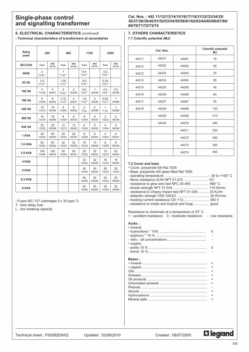
6. ElECTriCal CharaCTEriSTiCS (continued)
- Technical characteristics of transformers at secondaries
ratingpower
24V 48V 115V 230V
iEC/CSa fuseMCB
Cat. No.fuse
MCB Cat. No.
fuseMCB
Cat. No.fuse
MCB Cat. No.
40Va 2T2 AL(1)
1T1 AL(1)
0,4T0.4AL(1)
0,2T0.2AL(1)
63 Va 2.5T2.5 AL(1)
1.25T1.25 AL(1)
0.5T0.5AL(1)
0.25T0.25 AL(1)
100 Va 4T4 AE
406391
2T2 AL(1)
206389
0.8T0.8AL(1)
106388
0.4T0.4AL(1)
0.506386
160 Va 813308
606392
3.15T3.15 AE(1)
406391
1.6T1.6AL(1)
206389
0.63T0.63 AL(1)
106388
250 Va 1013310
1006394
613306
806392
2T2 AL
206389
1T1 AL
106388
400 Va 1613316
1606396
813308
866393
413304
406391
213302
206389
630 Va 2513325
2506398
1213312
1306395
613306
606392
413304
306390
1 KVa 4014340
4006400
2013320
2006397
813308
806393
413304
406391
1.6 KVa 6315363
6306382
3214332
3206399
1613316
1306495
813308
806393
2.5 KVa 10015396
10006476
5014350
5006381
2013320
2006397
1013310
6306394
4 KVa 3214332
3206399
1613316
1606396
5 KVa 4014340
4006400
2013320
2013320
6.3 KVa 5014350
5006382
2513325
2506399
8 KVa 6315380
6306383
3214340
3206400
(1) Fuses IEC 127 (cartridges 5 x 20 type T)T : time delay fuseL : low breaking capacity
7. OThErS CharaCTEriSTiCS 7.1 Calorific potential (MJ)
Cat. Nos. Calorific potentialMJ
44211 44231 44261 16
44212 44232 44262 20
44213 44233 44263 25
44214 44234 44264 28
44215 44235 44265 40
44216 44236 44266 60
44217 44237 44267 55
44218 44238 44268 130
44239 44269 210
44240 44270 280
44271 230
44272 290
44273 300
44274 450
7.2 Cover and base • Cover, polyamide 6/6 Ral 7035• Base, polyamide 6/6 glass filled Ral 7000- operating temperature ............................................... - 30 to +100° C- flame resistance UL94 NFT 51-072 .......................... VO- resistance to glow wire test NFC 20-455 ................... 960° C- tensile strength NFT 51-034 ...................................... 110 N/mm2
- resistance to Charpy impact test NFT 51-035 ........... 33 KJ/m2
- dielectric strength VDE 0303/2 ................................... 20 KV/mm- tracking current resistance CEI 112............................ 300 V- resistance to molds and tropical and fungi.................. good.
Resistance to chemicals at a temperature of 23° C+ : excellent resistance 0 : moderate resistance - : low resistance
acids : • mineral- hydrochloric ″ 10% .................................................. 0- sulphuric ″ 10 % ...................................................... -- nitric - all concentrations ......................................... -• organic- acetic 10 % .............................................................. 0- formic 10 % ............................................................. -
Bases :• mineral ..................................................................... +• organic ..................................................................... +Oils ............................................................................. +Greases ...................................................................... +Oil products ................................................................ +Chlorinated solvents ................................................... +Phenols ...................................................................... -Alcools ........................................................................ +Hydrocarbons ............................................................. +Mineral salts ............................................................... +
Technical sheet : F00282EN/02 Updated : 02/06/2010 Created : 06/07/2005
5/5