single pull macgregor type hatch cover
DESCRIPTION
HAtch cover type.TRANSCRIPT
i
SINGLE PULL MACGREGOR TYPE HATCH
COVER
A PROJECT REPORT
Submitted by
MANU SHARMA
MUHAMMED ASIM M T
NASIR ALI
NIRAJ KUMAR
NITHIN GOPAL
NITHIN XAVIER
In partial fulfilment for the award of the degree
of
BACHELOR OF TECHNOLOGY
IN
MARINE ENGINEERING
K M SCHOOL OF MARINE ENGINEERING
COCHIN UNIVERSITY OF SCIENCE AND TECHNOLOGY
COCHIN-682022
JULY 2011
ii
CERTIFICATE
This is to certify that the seminar project entitled “SINGLE PULL
MACGREGOR TYPE HATCH COVER” submitted by MANU SHARMA,
NASIR ALI, MUHAMMED ASIM M T, NIRAJ KUMAR, NITHIN
GOPAL S A, NITHIN XAVIER to the department of Kunjali Marakkar School
of Marine Engineering towards the partial fulfilment of the requirements for the
VIII semester of the B.Tech Degree course in Marine Engineering of Cochin
University of Science and Technology, is a bonafide record of work carried out
by him.
Head of the Department Project guide
K M School of Marine Engineering Prof. Dr. Sasikumar P.V.
Cochin University of Science and Technology
iii
ACKNOWLEDGEMENT
First of all we helmed in all humbleness and gracefulness to acknowledge our depth
regards to all who helped team to put this topic, well above the level of simplicity
and into something concrete.
We express our deep sense of gratitude to Director Prof K.A Simon for providing
necessary facilities.
We are very thankful to our project guide Prof. Dr.Sasikumar P.V who was always
there to show us the right track when team needed the help and guided us in
different matters regarding to project. He gave us moral support and guide in
different matters regarding to project report and presentation and is very kind and
patient while suggesting us the outline and structure of project report. .
We are equally thankful to our project coordinator Prof. N.G. Nair for his valuable
help.
We record our sincere thanks to course coordinator Prof. Roy.V.Paul for his
valuable suggestion
Last but not least, we would like to thank our parents and friends and all others who
helped us a lot in gathering different information, collecting data and guided us
from time to time in making the project despite of their busy schedule.
iv
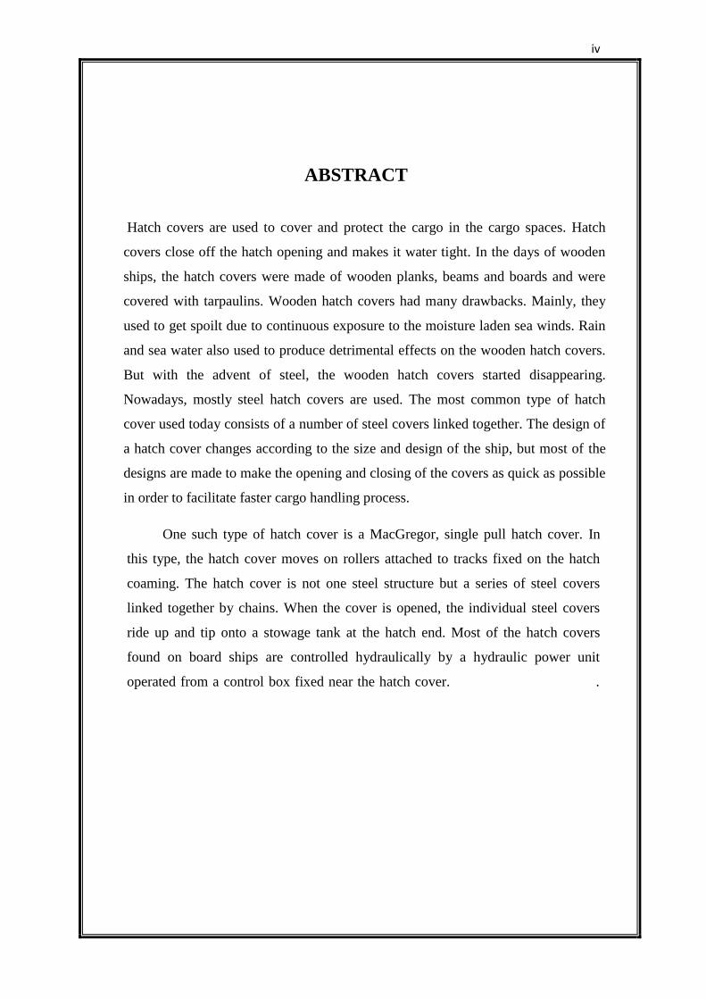
ABSTRACT
Hatch covers are used to cover and protect the cargo in the cargo spaces. Hatch
covers close off the hatch opening and makes it water tight. In the days of wooden
ships, the hatch covers were made of wooden planks, beams and boards and were
covered with tarpaulins. Wooden hatch covers had many drawbacks. Mainly, they
used to get spoilt due to continuous exposure to the moisture laden sea winds. Rain
and sea water also used to produce detrimental effects on the wooden hatch covers.
But with the advent of steel, the wooden hatch covers started disappearing.
Nowadays, mostly steel hatch covers are used. The most common type of hatch
cover used today consists of a number of steel covers linked together. The design of
a hatch cover changes according to the size and design of the ship, but most of the
designs are made to make the opening and closing of the covers as quick as possible
in order to facilitate faster cargo handling process.
One such type of hatch cover is a MacGregor, single pull hatch cover. In
this type, the hatch cover moves on rollers attached to tracks fixed on the hatch
coaming. The hatch cover is not one steel structure but a series of steel covers
linked together by chains. When the cover is opened, the individual steel covers
ride up and tip onto a stowage tank at the hatch end. Most of the hatch covers
found on board ships are controlled hydraulically by a hydraulic power unit
operated from a control box fixed near the hatch cover. .
v
TABLE OF CONTENTS
Page no.
CERTIFICATE ii
ACKNOWLEDGEMENT iii
ABSTRACT iv
TABLE OF CONTENTS v
LIST OF FIGURES ix
LIST OF TABLES xii
CHAPTER 1 - INTRODUCTION 1
1.1 Hatch Cover and Their Function. 2
1.2 Early Hatch Cover. 3
1.3 Failing of Wooden Hatches. 5
1.3.1 Safety and Security 5
1.3.2 Maintenance 6
1.3.3 Cargo Working 6
1.4 Steel Hatches After 1927 6
CHAPTER 2 - TYPES OF STEEL HATCH COVERS 9
2.1 Single Pull. 11
2.2 Side Rolling. 12
2.3 Folding and Multi Type 13
2.4 Lift Away 14
2.5 Piggy Back. 15
2.6 Stacking Covers 16
2.7 Reefers Hatch Covers. 17
2.8 Spring Loaded Covers. 18
CHAPTER 3 - GENERAL REQUIREMENT 19
3.1 Regulatory Requirements. 19
3.1.1 Rule Governing Access Equipment 19
3.1.2 International Load Line Convention, 1966. 19
3.1.3 Freeboard. 20
3.1.4 Freeboard Deck. 21
3.1.5 Weather-Tightness and Water-Tightness. 22
vi
3.1.6 Statutory Regulations. 23
3.2 General Considerations for Access Equipment. 23
3.2.1 Coaming Height 23
3.2.2 Cover Stowage 25
3.2.3 Deck Opening 25
3.2.4 Drainage 26
3.3 Specific Design Requirements for Hatch Covers. 27
3.3.1 Hatch Covers 27
3.3.1.1 Structural Regulations. 27
3.3.1.2 Cleats. 29
3.3.1.3 Loads. 30
3.3.1.4 Scantling. 30
3.3.1.5 Deformation. 31
3.3.2 Seals 34
3.3.2.1 Gaskets Material 35
3.3.2.2 Compression Bar. 35
3.4 Construction Materials. 35
3.4.1 Higher Tensile Steel (HTS) 36
3.4.2 Aluminium 36
3.4.3 Glass Reinforced Plastic (GRP) 37
3.4.4 Wood 37
CHAPTER 4 - OPERATIONAL AND SAFETY ASPECTS 38
4.1 Basic Advice 38
4.2 Monitoring and Inspection 40
4.3 Heavy Weather Precaution 42
4.4 Safety when Working with Hatch Covers 43
4.5 Procedure to Open and Close Hatch Covers 48
4.6 Maintenance and Repair 50
CHAPTER 5 - SINGLE PULL MACGREGOR TYPE HATCH COVER
DESIGN 54
5.1 Parts Design 56
5.1.1 Hold Design. 56
5.1.2 Hatch Opening Dimensions. 56
5.1.3 Hatch Coaming Design. 57
vii
5.1.4 Hatch Covers Design. 58
5.1.5 Track 1 Design. 59
5.1.6 Rising Track Design (Track 2). 60
5.1.7 Jack Design. 60
5.1.8 Crane Space Design 61
5.1.9 Motor Casing 61
5.1.10 Motor Specifications 62
5.1.11 Pulley Design 62
5.1.12 Rope 63
5.1.13 Reduction Gear Design 63
5.1.14 Ladder Design 63
5.1.15 Bulwark Design 64
5.2 Material Selection 65
CHAPTER 6 - FABRICATION 67
6.1 Fabrication of Cargo Hold 67
6.2 Fabrication of Hatch Way 68
6.3 Hatch Coaming Fabrication 69
6.4 Hatch Stay Fabrication 70
6.5 Fabrication of Side & End Dog 70
6.6 Fabrication of Hatch Cover. 71
6.7 Sliding Track Fabrication. 73
6.8 Fabrication of Rising Track. 75
6.9 Fabrication of Crane Space 76
6.10 Motor Reduction Gear Pulley Fabrication 77
6.11 Fabrication of Bulwark 77
6.12 Fabrication of Ladder 78
CHAPTER 7 - ASSEMBLY OF FABRICATED PARTS 79
7.1 Assembly Between Cargo Hold and Hatch Coaming 80
7.2 Assembly of Hatch Stay on Coaming 80
7.3 Assembly of Side Dogs and End Dogs on Coaming 81
7.4 Assembly of Sliding Tracks 82
7.5 Assembly of Rising Track 82
7.6 Assembly of Hatch Cover 83
7.7 Assembly of Crane Space into Cargo Hold. 84
viii
7.8 Assembly of Motor Pulley Gear Arrangement into Cargo Hold 84
7.9 Assembly of Bulwark 84
7.10 Assembly of Ladder 85
7.11 Assembly of Locking Arrangement 86
7.12 Assembly of Wire Rope 86
CHAPTER 8 - TESTS AND TRIALS 88
8.1 Water Hose Leak Detection Test 88
8.2 Ultrasonic Leak Detection Test 88
8.3 Putty or Moulding Clay Test 89
8.4 Chalk Test 89
8.5 Tolerance Test for Hatch Covers 89
8.6 Results 90
CHAPTER 9 - CONCLUSION 91
REFERENCES 92
ix
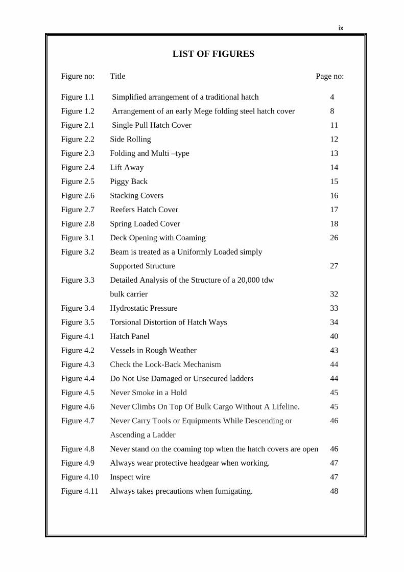
LIST OF FIGURES
Figure no: Title Page no:
Figure 1.1 Simplified arrangement of a traditional hatch 4
Figure 1.2 Arrangement of an early Mege folding steel hatch cover 8
Figure 2.1 Single Pull Hatch Cover 11
Figure 2.2 Side Rolling 12
Figure 2.3 Folding and Multi –type 13
Figure 2.4 Lift Away 14
Figure 2.5 Piggy Back 15
Figure 2.6 Stacking Covers 16
Figure 2.7 Reefers Hatch Cover 17
Figure 2.8 Spring Loaded Cover 18
Figure 3.1 Deck Opening with Coaming 26
Figure 3.2 Beam is treated as a Uniformly Loaded simply
Supported Structure 27
Figure 3.3 Detailed Analysis of the Structure of a 20,000 tdw
bulk carrier 32
Figure 3.4 Hydrostatic Pressure 33
Figure 3.5 Torsional Distortion of Hatch Ways 34
Figure 4.1 Hatch Panel 40
Figure 4.2 Vessels in Rough Weather 43
Figure 4.3 Check the Lock-Back Mechanism 44
Figure 4.4 Do Not Use Damaged or Unsecured ladders 44
Figure 4.5 Never Smoke in a Hold 45
Figure 4.6 Never Climbs On Top Of Bulk Cargo Without A Lifeline. 45
Figure 4.7 Never Carry Tools or Equipments While Descending or 46
Ascending a Ladder
Figure 4.8 Never stand on the coaming top when the hatch covers are open 46
Figure 4.9 Always wear protective headgear when working. 47
Figure 4.10 Inspect wire 47
Figure 4.11 Always takes precautions when fumigating. 48
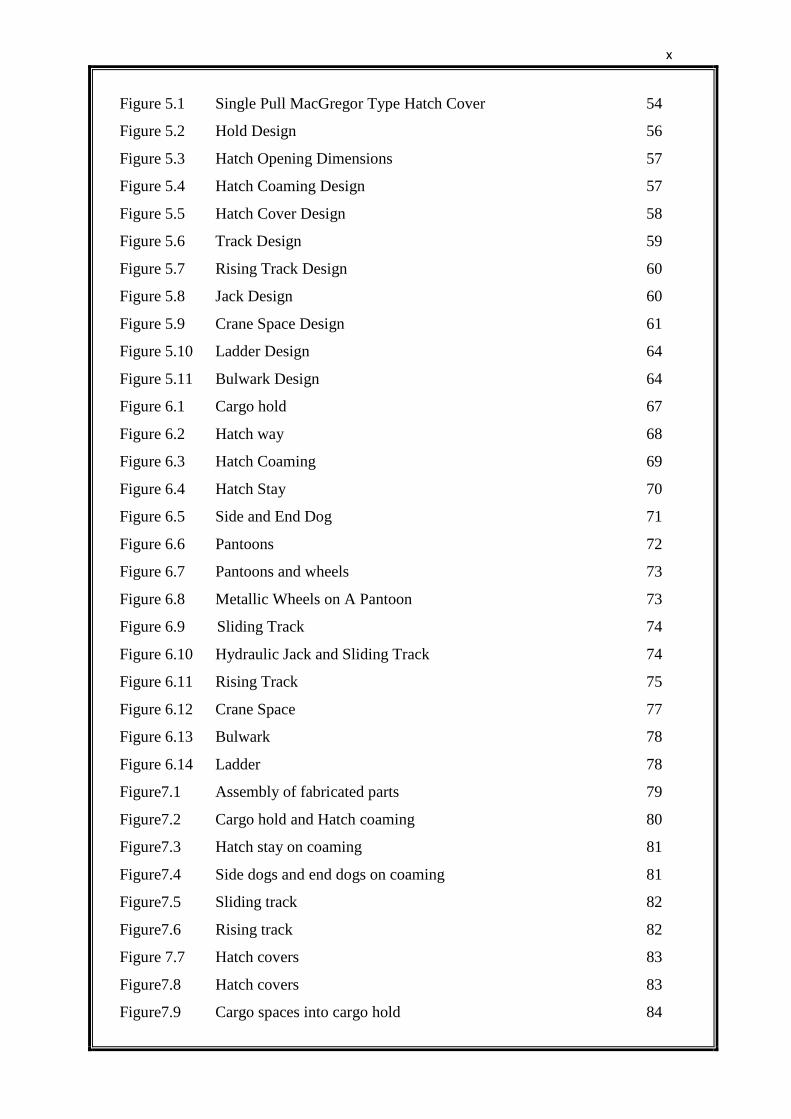
x
Figure 5.1 Single Pull MacGregor Type Hatch Cover 54
Figure 5.2 Hold Design 56
Figure 5.3 Hatch Opening Dimensions 57
Figure 5.4 Hatch Coaming Design 57
Figure 5.5 Hatch Cover Design 58
Figure 5.6 Track Design 59
Figure 5.7 Rising Track Design 60
Figure 5.8 Jack Design 60
Figure 5.9 Crane Space Design 61
Figure 5.10 Ladder Design 64
Figure 5.11 Bulwark Design 64
Figure 6.1 Cargo hold 67
Figure 6.2 Hatch way 68
Figure 6.3 Hatch Coaming 69
Figure 6.4 Hatch Stay 70
Figure 6.5 Side and End Dog 71
Figure 6.6 Pantoons 72
Figure 6.7 Pantoons and wheels 73
Figure 6.8 Metallic Wheels on A Pantoon 73
Figure 6.9 Sliding Track 74
Figure 6.10 Hydraulic Jack and Sliding Track 74
Figure 6.11 Rising Track 75
Figure 6.12 Crane Space 77
Figure 6.13 Bulwark 78
Figure 6.14 Ladder 78
Figure7.1 Assembly of fabricated parts 79
Figure7.2 Cargo hold and Hatch coaming 80
Figure7.3 Hatch stay on coaming 81
Figure7.4 Side dogs and end dogs on coaming 81
Figure7.5 Sliding track 82
Figure7.6 Rising track 82
Figure 7.7 Hatch covers 83
Figure7.8 Hatch covers 83
Figure7.9 Cargo spaces into cargo hold 84
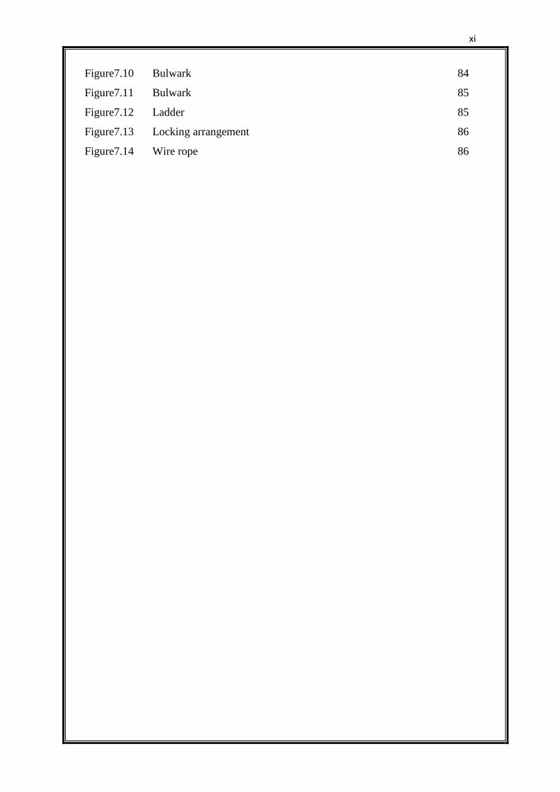
xi
Figure7.10 Bulwark 84
Figure7.11 Bulwark 85
Figure7.12 Ladder 85
Figure7.13 Locking arrangement 86
Figure7.14 Wire rope 86
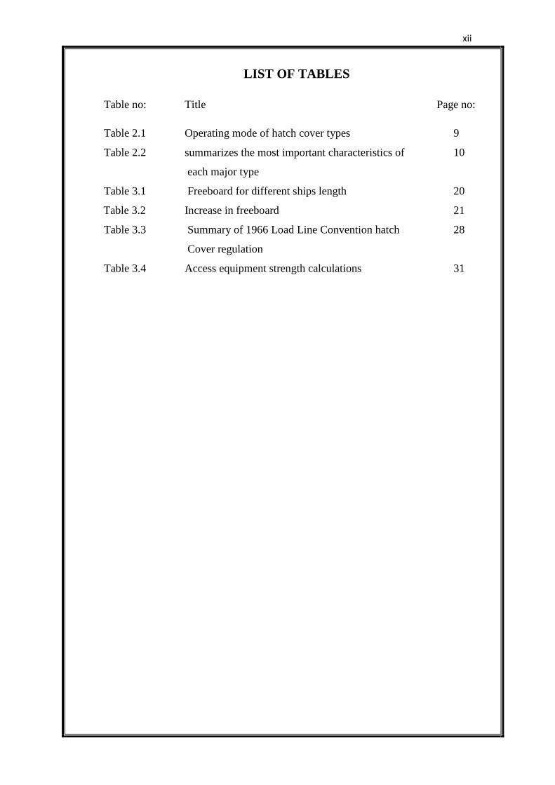
xii
LIST OF TABLES
Table no: Title Page no:
Table 2.1 Operating mode of hatch cover types 9
Table 2.2 summarizes the most important characteristics of 10
each major type
Table 3.1 Freeboard for different ships length 20
Table 3.2 Increase in freeboard 21
Table 3.3 Summary of 1966 Load Line Convention hatch 28
Cover regulation
Table 3.4 Access equipment strength calculations 31
1
CHAPTER 1 - INTRODUCTION
The classic modern hatch cover is the ‘single pull’ which remains the most
common of the all the various forms now in service and may rightly be described
as the natural successor to traditional beams and boards. This cover derives its
name from its immediate predecessor, the ‘multi-pull’ cover, which consisted of a
series of individual panels similar to those of the single pull, but unconnected.
Each panel had to be rigged before being pulled one at a time into stowage.
The complete cover consists of a number of narrow panels which span the
hatchway and are linked together by chains. In the closed position, the panel sides
sit firmly which takes the weight of the cover. Rubber gasket was attached to the
side and end dogs over which weight of panel comes forming a watertight seal.
Extending from the side coamings at the end of the hatchway where the covers
are stowed are steel rails which the individual hatch panels to be transferred to
their stowage location when the hatch is opened.
To open a hatch hold cover, the securing cleats are first freed and each
panel is raised onto its wheel by portable jacks. Entire cover is free to move in a
fore and aft direction with its wheel rolling between guides on the top of the
coaming. It is set in motion by means of a wire (sometimes called a bull wire) led
from a motor wheel and attached to the centre of the furthest edge of the leading
panel i.e. the panel which goes into stowage first and comes out of stowage last.
As the wire is tightened, the panels are each pushed beyond the end coaming. On
reaching the end of the hatchway; the weight of each panel is transferred from its
wheels to balancing rollers situated near its mid length which engage with the rail
extensions of the side coaming. The centre of gravity of each panel is slightly
towards the stowage end of the panel from the rollers so that once the panel is
supported from them, it tips into vertical position. It is then pushed further
towards the end of the stowage space by the next panel to arrive at the hatchway
end. When the hatch is completely open, each panel stands vertically in the
stowage space, and all are kept in place with retaining chains.
To close a single pull cover, the direction of rotation of motor is reversed.
This cause the first panel to leaves its stowage position, its tip through 90 degree
2
about its roller to land horizontally with its wheels resting on the coaming. It is
then pulled further over the hatchway and the chain linking it to the next panel
becomes taut with the result it too is set in motion.
On reaching the end of the stowage space, the second panel tips lie
horizontally on the coaming behind the first and together they pull across the
hatchway. The process is repeated with the third and fourth panels, ending only
when all are lying flat on the coamings and the hatch is completely covered.
1.1 HATCH COVERS AND THEIR FUNCTION
The purpose and function of a hatch cover and its coamings is to prevent ingress
of water into a cargo hold after a large opening has been cut in the deck for cargo
access. Hatch covers are a moveable structure designed to a weather tight
standard.
1.1.1 Hatch Cover Construction
Typically hatch covers are lightweight steel grillages. Modern design methods
using finite element technology enable more efficient material distribution which
results in lighter (thinner) structures.
Construction from high tensile steel results in even thinner plate being
used. For this reason these lightweight structures must be ‘handled with care’.
Prevention of corrosion is essential – safety margins are finite.
1.1.2 Hatch Cover Function
Hatch covers provide a primary structural and weather tight barrier to prevent
water ingress into cargo holds. Rigorous inspection, regular maintenance and
prompt repair of damaged covers, securing’s and supports are essential to
maintain fitness for purpose and, in particular:-
To maintain sufficient strength to resist green seas landing on hatches in
extreme weather;
To maintain a barrier against ingress of water during normal seagoing
weather conditions.
Failure to maintain hatch covers correctly can lead to physical loss of a
cover in extreme weather and hold flooding and possible foundering. Minor
3
leakage can cause cargo damage and, if over a prolonged period, damage to the
ship’s internal structure. Long-term structural decline can lead to structural
collapse and total loss.
1.2 EARLY HATCH COVERS
The upper deck hatches of early steamships, in common with those of sailing
ships, were small by present standards: four meters by two would not have been
untypical hatchway dimensions, even for ocean going vessels in the mid-19th
century. Deck openings were bounded by vertical coamings and spanned by
wooden boards usually laid athwart ships: water tightness was maintained by
tarpaulins spread over the boards and secured by wedges and cleats at the
coamings, an arrangement which had then been in use for centuries. Web beams
were sometimes placed across the largest hatchways but it was not until 1879 that
their use became mandatory for all vessels classed with Lloyd’s Register of
Shipping having hatchways more than 12 feet long. Coamings were required to be
of iron constructions. No minimum height was specified and it was not until forty
years later that they appeared in Lloyd’s Rules. Hatch boards were made of solid
woods 63 mm thick and of such an overall size that they could be handled
manually. Since they were laid transversely across the hatchway it was necessary
to use ‘fore and afters’ to reduce their unsupported span. These were the heavy
baulks of timber placed longitudinally across the hatchway, on the top of the
transverse iron beams and supported at each end by brackets attached to the
coamings. The hatch boards, in turn, were placed across the fore and after which
were so spaced that the unsupported span of the boards did not exceed the
maximum allowed.
After the turn of the 20th
century, the practice of arranging hatch boards
longitudinally began to be adopted. There were sound reasons for this change. A
typical cargo ship hatch,7.5m(25 ft) long and 5 m(16 ft) wide, with athwart ship
hatch boards, would have been fitted with two transverse web beams and three
fore afters which, because of their overall length would each have been made up
in three pieces, one for every beam space as shown in figure 1.1. With
longitudinal hatch boards the same hatch would have required no more than four
transverse beams space 1.5 m apart each of lighter construction than the two webs
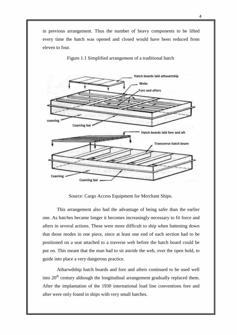
4
in previous arrangement. Thus the number of heavy components to be lifted
every time the hatch was opened and closed would have been reduced from
eleven to four.
Figure 1.1 Simplified arrangement of a traditional hatch
Source: Cargo Access Equipment for Merchant Ships.
This arrangement also had the advantage of being safer than the earlier
one. As hatches became longer it becomes increasingly necessary to fit force and
afters in several actions. These were more difficult to ship when battening down
that those modes in one piece, since at least one end of each section had to be
positioned on a seat attached to a traverse web before the hatch board could be
put on. This meant that the man had to sit astride the web, over the open hold, to
guide into place a very dangerous practice.
Atharwdship hatch boards and fore and afters continued to be used well
into 20th
century although the longitudinal arrangement gradually replaced them.
After the implantation of the 1930 international load line conventions fore and
after were only found in ships with very small hatches.
5
All types of wooden hatch were made watertight by means of tarpaulins
and this method is still employed in those ships with traditional hatches that
remain in service. The use of wooden hatch cover has declined throughout much
of this century to the extent that it is now almost unthinkable that they should be
fitted in modern vessel of any size. It is interesting therefore, to consider the
reason for their demise. These fall into three broad categories, namely safety and
security, cargo working and maintenance.
1.3 FAILINGS OF WOODEN HATCHES
1.3.1 Safety and Security
It is impossible to exaggerate the importance and secure hatch covers; there can be
no question that a ship’s survival may depend upon having them. But how
efficient are wooden hatch covers?
Tarpaulins are the most vulnerable component of traditional hatch covers.
There are several common reasons for tarpaulin failure. Slackening of wedges is
one of the most important factor. Chaffing is another serious source of weakness,
especially at the coamings. Tarpaulins are also liable to suffer damage every time
that they are removed for working cargo.
Security of the wooden hatches also arose as a result of the comparatively
large size of the hatchways of many of the ships, especially colliers, then entering
service. Not only were the hatchways longer and wider than had been the customs
up to that time, but the ratio of hatch width to overall beam was often greater too.
This was particularly apparent in ships employed in the carriage of bulk cargoes
and some of the most extreme examples were to be amongst self-trimming
colliers where hatch width/ship beam ratios often exceed 0.6.
Individual hatch boards were laid loosely on top of the beams in a normal
hatchway and they could easily be shipped accidently. In order to prevent this,
interlocking boards were developed. These could be handled manually in the
usual manner but once landed on the beams; they were retained in place by a
simple locking device which was claimed by its manufacturer to enhance the
safety of a ship, should it lose its tarpaulins, by preventing the boards from being
washed away by the sea.
6
1.3.2 Maintenance
The maintenance of the wooden hatches is expensive in both labour and materials.
Although individual components were simple and inexpensive, there were so
many of them in a typical hatch and they were so easily damaged through
continued hard use that the total cost of replacement so often substantial. Wedges
which are vital to the security of the hatches were individually very cheap but they
were frequently lost or misused.
Hatch boards too had to be replaced frequently. Tarpaulins used for
traditional hatches were easily chafed and in some ships one man could well have
been employed continuously for their repair.
1.3.3 Cargo Working
Time spent in port affects the overall economics of operating ships. Attention was
given for higher cargo handling rates and faster turnaround times, and time spent
for opening and closing hatches. This become increasingly apparent as hatchways
became larger. Every hatch component had to be handled separately; tarpaulins
had to be folded back, each hatch board had to be removed manually, each beam
had to be lifted from its seat by derrick and winch or shore crane, and the larger
the hatchway, the more items there were to be handled.
1.4 STEEL HATCHES AFTER 1927
The earliest satisfactory hatch cover produced by the brothers Joseph and Robert
MacGregor, two naval architects from Tyneside, was of the hinged type. It
consists to two large steel slabs, each spanning half the hatchway and hinged at
the side coamings. When opened by winch and derrick, the slabs rotated through
180 degree so that they rested on the bulwarks to form a convenient platform for
working cargo (although obstructing the gangway along the deck). Like other slab
hatches they were kept secure and watertight in the conventional manner and their
hinges were cunningly built into the coamings so as not to impair the
effectiveness of their tarpaulins. However, it was the announcement in 1928 of a
horizontal rolling cover which did not require tarpaulins that marked the real
beginning of the long association of the Macgregor name with steel hatch covers,
which continues to this day.
7
The first horizontal rolling built to the design patented by MacGregor &
king Ltd. Was installed over the aftermost hatchway of the 9000tdw motor ship
sheaf holme which left the Sunderland yard of her builder, Wm. Pickersgill, in
August1929 amid rather more publicity than she would otherwise have merited.
The event was important because it was not the first time that a hatch cover had
been put into service that was easily operated manually, yet depended on
tarpaulins for water tightness nor did it forgo any of the strength with which
previous steel covers had been endowed.
The earliest horizontal rolling covers produced by Macgregor and king
(subsequently known as Macanking) came in two forms, although both were
basically similar. The first was fitted in fairly small hatchways and consists of two
moveable sections fabricated out of steel plate stiffened by channels bars or bulbs
angles, with a skirt around their perimeters which rested on the coaming when the
cover was closed. They revolved about eccentric bushes which could be rotated so
that the clear height of the lower edge of the cover above the coaming could be
varied.
In the closed position, with the hatch secured for sea, the bushes were
aligned so that the perimeter of the cover rested on the coaming throughout its
entire length. To open the hatch, the bushes were rotated through half a turn with
a marlin spike, thus raising the cover so that it could be easily pulled along on its
wheels. This arrangement has become a feature of many MacGregor hatches
since.
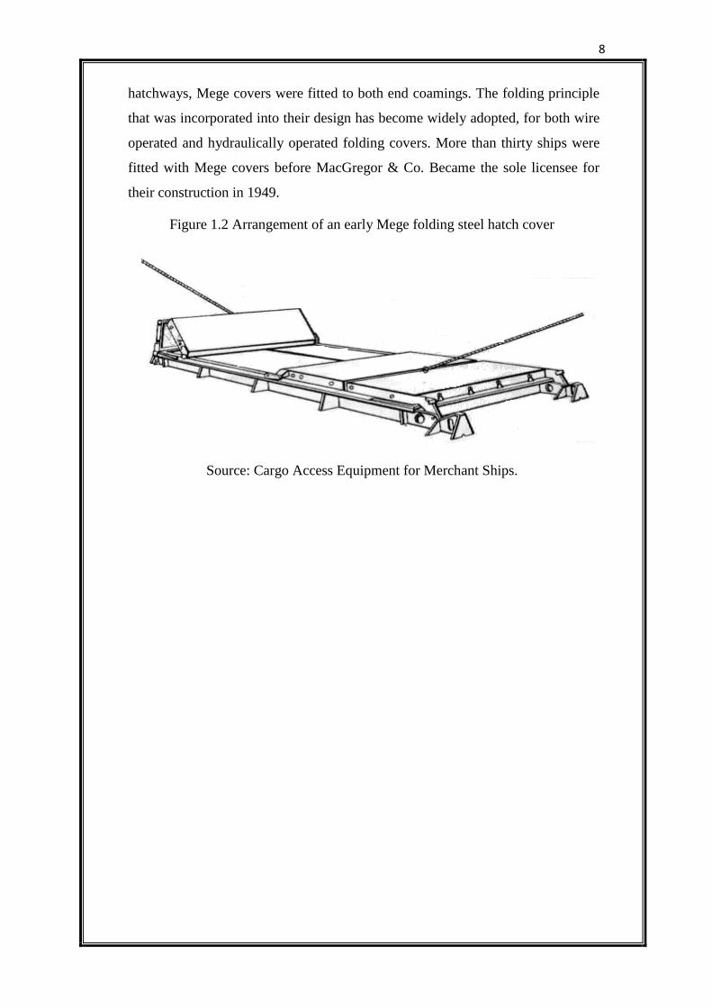
In France in 1934, Captain Mege, of Louis Dreyfus Cie, patented folding
steel hatch covers which were first fitted in the cargo ship Louis L.D. two years
later. They considered of double panels hinged together and to the end coamings,
but, unlike the von Tell covers, they were opened by lifting the panel nearer the
coaming hinge. As it was raised, the second panel was pulled towards the end of
the hatchway, supported on two trailing wheels which ran along the coaming,
until both panels were stowed together vertically. In this way a folding hatch
cover could be opened in one operation instead of two. Fig 1.2 shows an early
Mege folding steel hatch cover. Closing was carried out by simply allowing the
fold hinge to open under the combined weight of the two panels until both were
in position resting flat on coaming to which they were secured by bolts. In long
8
hatchways, Mege covers were fitted to both end coamings. The folding principle
that was incorporated into their design has become widely adopted, for both wire
operated and hydraulically operated folding covers. More than thirty ships were
fitted with Mege covers before MacGregor & Co. Became the sole licensee for
their construction in 1949.
Figure 1.2 Arrangement of an early Mege folding steel hatch cover
Source: Cargo Access Equipment for Merchant Ships.
9
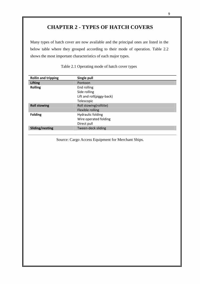
CHAPTER 2 - TYPES OF HATCH COVERS
Many types of hatch cover are now available and the principal ones are listed in the
below table where they grouped according to their mode of operation. Table 2.2
shows the most important characteristics of each major types.
Table 2.1 Operating mode of hatch cover types
Source: Cargo Access Equipment for Merchant Ships.
Rollin and tripping Single pull
Lifting Pontoon Rolling End rolling
Side rolling Lift and roll(piggy-back) Telescopic
Roll stowing Roll stowing(rolltite) Flexible rolling
Folding Hydraulic folding Wire operated folding Direct pull
Sliding/nesting Tween-deck sliding
10
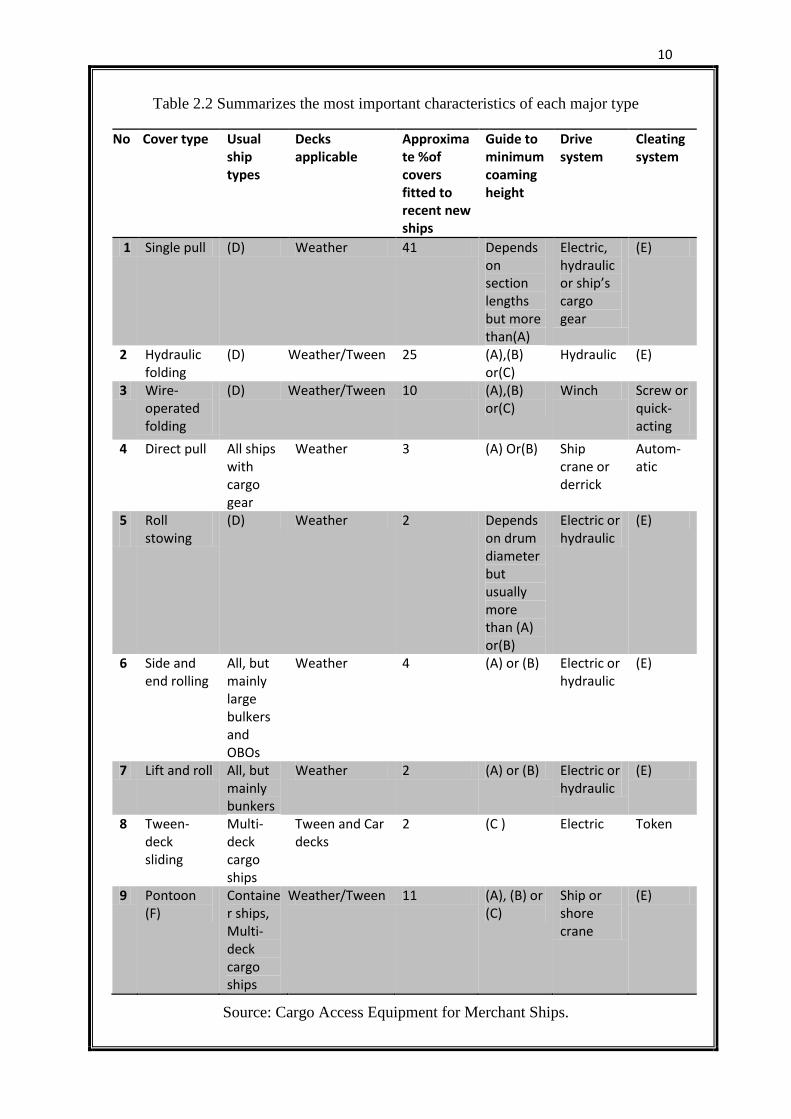
Table 2.2 Summarizes the most important characteristics of each major type
NNo Cover type Usual ship types
Decks applicable
Approximate %of covers fitted to recent new ships
Guide to minimum coaming height
Drive system
Cleating system
1 Single pull (D) Weather 41 Depends on section lengths but more than(A)
Electric, hydraulic or ship’s cargo gear
(E)
2 Hydraulic folding
(D) Weather/Tween 25 (A),(B) or(C)
Hydraulic (E)
3 Wire-operated folding
(D) Weather/Tween 10 (A),(B) or(C)
Winch Screw or quick-acting
4 Direct pull All ships with cargo gear
Weather 3 (A) Or(B) Ship crane or derrick
Autom-atic
5.
Roll stowing
(D) Weather 2 Depends on drum diameter but usually more than (A) or(B)
Electric or hydraulic
(E)
6 Side and end rolling
All, but mainly large bulkers and OBOs
Weather 4 (A) or (B) Electric or hydraulic
(E)
7 Lift and roll All, but mainly bunkers
Weather 2 (A) or (B) Electric or hydraulic
(E)
8 Tween-deck sliding
Multi-deck cargo ships
Tween and Car decks
2 (C ) Electric Token
9 Pontoon (F)
Container ships, Multi-deck cargo ships
Weather/Tween 11 (A), (B) or (C)
Ship or shore crane
(E)
Source: Cargo Access Equipment for Merchant Ships.
11
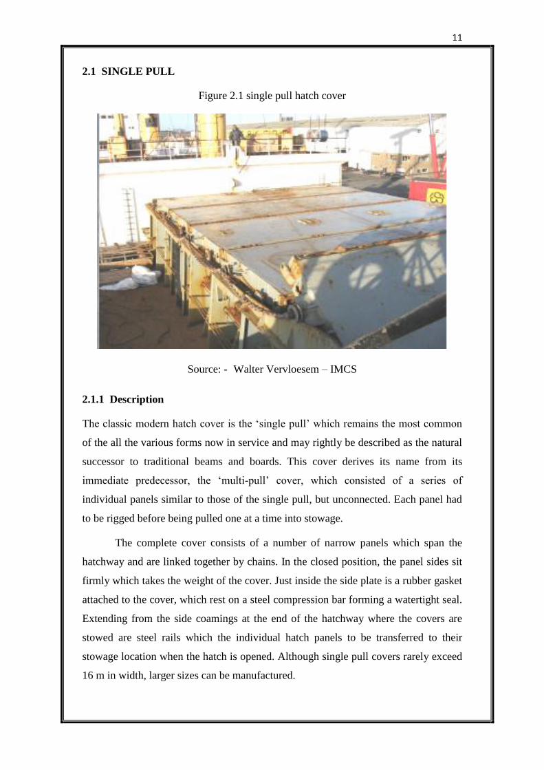
2.1 SINGLE PULL
Figure 2.1 single pull hatch cover
Source: - Walter Vervloesem – IMCS
2.1.1 Description
The classic modern hatch cover is the ‘single pull’ which remains the most common
of the all the various forms now in service and may rightly be described as the natural
successor to traditional beams and boards. This cover derives its name from its
immediate predecessor, the ‘multi-pull’ cover, which consisted of a series of
individual panels similar to those of the single pull, but unconnected. Each panel had
to be rigged before being pulled one at a time into stowage.
The complete cover consists of a number of narrow panels which span the
hatchway and are linked together by chains. In the closed position, the panel sides sit
firmly which takes the weight of the cover. Just inside the side plate is a rubber gasket
attached to the cover, which rest on a steel compression bar forming a watertight seal.
Extending from the side coamings at the end of the hatchway where the covers are
stowed are steel rails which the individual hatch panels to be transferred to their
stowage location when the hatch is opened. Although single pull covers rarely exceed
16 m in width, larger sizes can be manufactured.
12
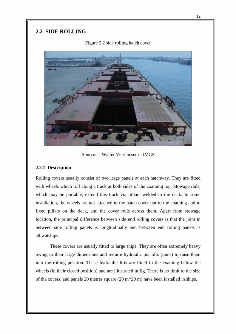
2.2 SIDE ROLLING
Figure 2.2 side rolling hatch cover
Source: - Walter Vervloesem - IMCS
2.2.1 Description
Rolling covers usually consist of two large panels at each hatchway. They are fitted
with wheels which roll along a track at both sides of the coaming top. Stowage rails,
which may be portable, extend this track via pillars welded to the deck. In some
installation, the wheels are not attached to the hatch cover but to the coaming and to
fixed pillars on the deck, and the cover rolls across them. Apart from stowage
location, the principal difference between side end rolling covers is that the joint in
between side rolling panels is longitudinally and between end rolling panels is
athwatships.
These covers are usually fitted to large ships. They are often extremely heavy
owing to their large dimensions and require hydraulic pot lifts (rams) to raise them
into the rolling position. These hydraulic lifts are fitted to the coaming below the
wheels (in their closed position) and are illustrated in fig. There is no limit to the size
of the covers, and panels 20 metres square (20 m*20 m) have been installed in ships.
13
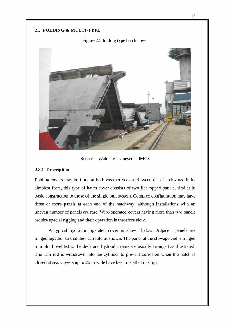
2.3 FOLDING & MULTI-TYPE
Figure 2.3 folding type hatch cover
Source: - Walter Vervloesem - IMCS
2.3.1 Description
Folding covers may be fitted at both weather deck and tween deck hatchways. In its
simplest form, this type of hatch cover consists of two flat topped panels, similar in
basic construction to those of the single pull system. Complex configuration may have
three or more panels at each end of the hatchway, although installations with an
uneven number of panels are rare. Wire-operated covers having more than two panels
require special rigging and their operation is therefore slow.
A typical hydraulic operated cover is shown below. Adjacent panels are
hinged together so that they can fold as shown. The panel at the stowage end is hinged
to a plinth welded to the deck and hydraulic rams are usually arranged as illustrated.
The ram rod is withdrawn into the cylinder to prevent corrosion when the hatch is
closed at sea. Covers up to 26 m wide have been installed in ships.
14
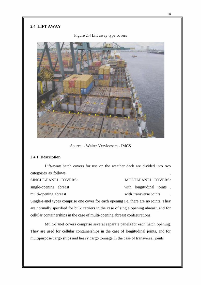
2.4 LIFT AWAY
Figure 2.4 Lift away type covers
Source: - Walter Vervloesem - IMCS
2.4.1 Description
Lift-away hatch covers for use on the weather deck are divided into two
categories as follows: .
SINGLE-PANEL COVERS: MULTI-PANEL COVERS:
single-opening abreast with longitudinal joints .
multi-opening abreast with transverse joints .
Single-Panel types comprise one cover for each opening i.e. there are no joints. They
are normally specified for bulk carriers in the case of single opening abreast, and for
cellular containerships in the case of multi-opening abreast configurations.
Multi-Panel covers comprise several separate panels for each hatch opening.
They are used for cellular containerships in the case of longitudinal joints, and for
multipurpose cargo ships and heavy cargo tonnage in the case of transversal joints
15
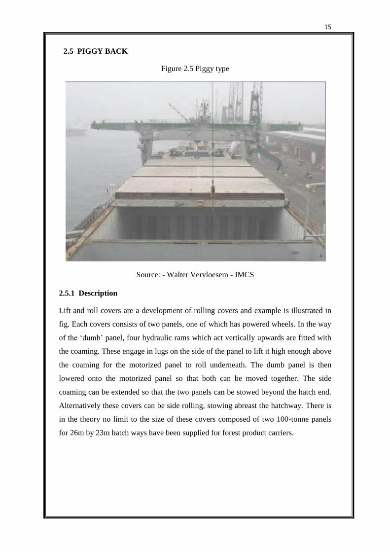
2.5 PIGGY BACK
Figure 2.5 Piggy type
Source: - Walter Vervloesem - IMCS
2.5.1 Description
Lift and roll covers are a development of rolling covers and example is illustrated in
fig. Each covers consists of two panels, one of which has powered wheels. In the way
of the ‘dumb’ panel, four hydraulic rams which act vertically upwards are fitted with
the coaming. These engage in lugs on the side of the panel to lift it high enough above
the coaming for the motorized panel to roll underneath. The dumb panel is then
lowered onto the motorized panel so that both can be moved together. The side
coaming can be extended so that the two panels can be stowed beyond the hatch end.
Alternatively these covers can be side rolling, stowing abreast the hatchway. There is
in the theory no limit to the size of these covers composed of two 100-tonne panels
for 26m by 23m hatch ways have been supplied for forest product carriers.
16
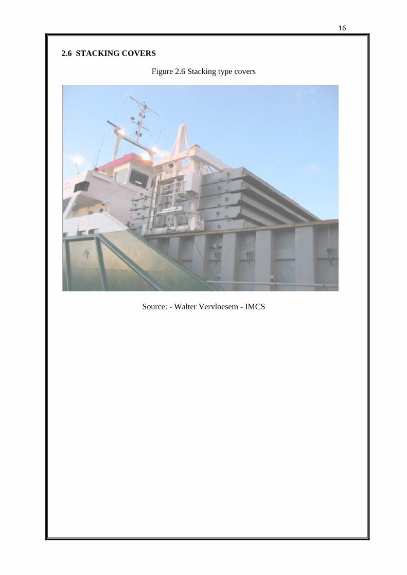
2.6 STACKING COVERS
Figure 2.6 Stacking type covers
Source: - Walter Vervloesem - IMCS
17
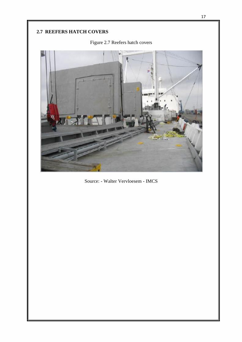
2.7 REEFERS HATCH COVERS
Figure 2.7 Reefers hatch covers
Source: - Walter Vervloesem - IMCS
18
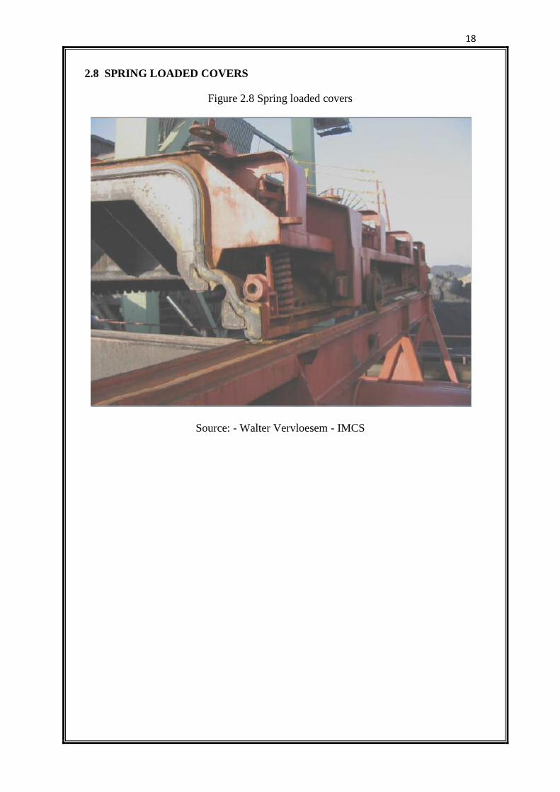
2.8 SPRING LOADED COVERS
Figure 2.8 Spring loaded covers
Source: - Walter Vervloesem - IMCS
19
CHAPTER 3 - GENERAL REQUIREMENTS
3.1 REGULATORY REQUIREMENTS
3.1.1 Rules Governing Cargo Access Equipment
Cargo ships exist to transport goods from one port to another to accomplish this; they
must have some means of getting cargo into and out of their holds. Thus ships must
have opening either in the weather deck, as in vertically loading vessels, or in the
bow, stern or side, as in horizontally loading vessels. These areas are all vulnerable to
damage at sea. Thus cargo access equipment must provide access in port while
keeping water out, during voyage. One of its prime functions is to ensure the safety of
ship, personnel and cargo. In order to maintain acceptable standards of safety at sea,
rules and regulations have been introduced over the years, many of which directly
concern access equipment.
3.1.2 International Load Line Convention, 1966
Probably the most important regulations that affect access equipment are those arising
from the 1966 load line convention which replaces the first international load line
convention in 1930 for determining the freeboard. It provides for two categories. It
provides for two categories of ship for freeboard purpose-Type. A ships which are
those designed to carry liquid cargoes in bulk and whose tanks have small access
openings and Type B which includes all other ships. Among Type B ships are certain
bulk carriers and ore carriers which are further sub-divided as follows:
(a) Ships of over 100 m length having steel hatch cover on all exposed hatchways
and which can remain afloat in satisfactory equilibrium with any one
compartment flooded. When the length exceeds 225 m, the machinery space is
also treated as a floodable compartment. These ships can have table B
freeboards given in table B and A summarized in table; such freeboard is
referred to as B-60.Tables A and B referred to the minimum freeboard laid
down by the Convention for type A and Type b ships.
(b) Ships which can withstand flooding of two adjacent compartments may be
assigned B-100 freeboard, virtually equal to type A ships.
20
Type B ships which are fitted with portable covers, e.g. beams and boards in
position 1 hatchways are required to have their freeboard increased above
those given in table B.
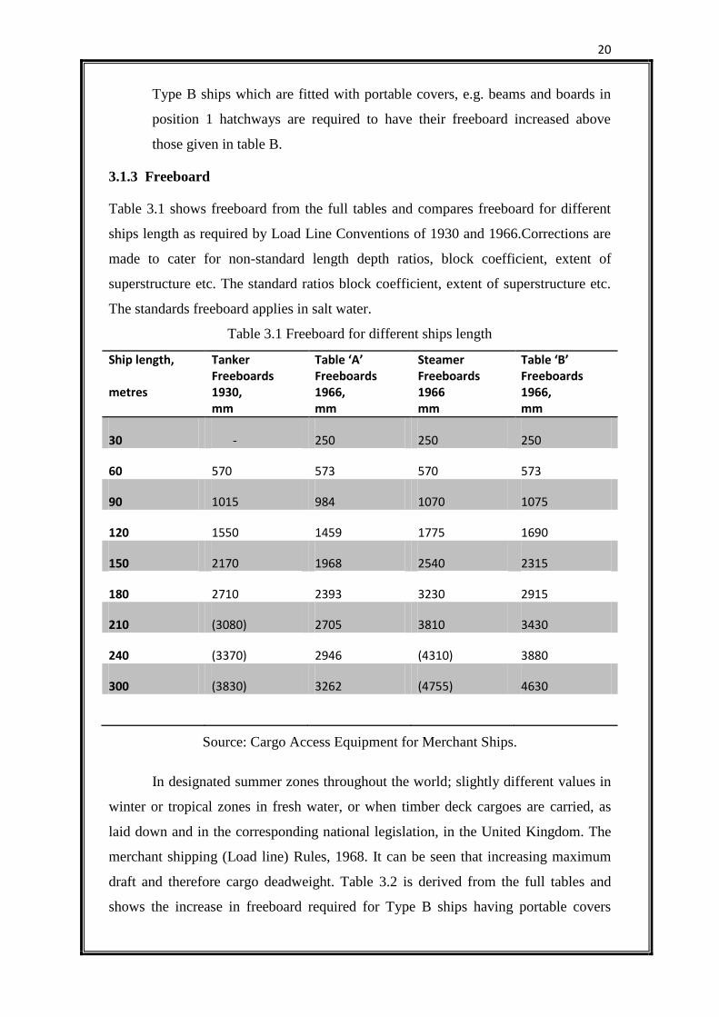
3.1.3 Freeboard
Table 3.1 shows freeboard from the full tables and compares freeboard for different
ships length as required by Load Line Conventions of 1930 and 1966.Corrections are
made to cater for non-standard length depth ratios, block coefficient, extent of
superstructure etc. The standard ratios block coefficient, extent of superstructure etc.
The standards freeboard applies in salt water.
Table 3.1 Freeboard for different ships length
Ship length, metres
Tanker Freeboards 1930, mm
Table ‘A’ Freeboards 1966, mm
Steamer Freeboards 1966 mm
Table ‘B’ Freeboards 1966, mm
30 - 250 250 250
60 570 573 570 573
90 1015 984 1070 1075
120 1550 1459 1775 1690
150 2170 1968 2540 2315
180 2710 2393 3230 2915
210 (3080) 2705 3810 3430
240 (3370) 2946 (4310) 3880
300 (3830) 3262 (4755) 4630
Source: Cargo Access Equipment for Merchant Ships.
In designated summer zones throughout the world; slightly different values in
winter or tropical zones in fresh water, or when timber deck cargoes are carried, as
laid down and in the corresponding national legislation, in the United Kingdom. The
merchant shipping (Load line) Rules, 1968. It can be seen that increasing maximum
draft and therefore cargo deadweight. Table 3.2 is derived from the full tables and
shows the increase in freeboard required for Type B ships having portable covers
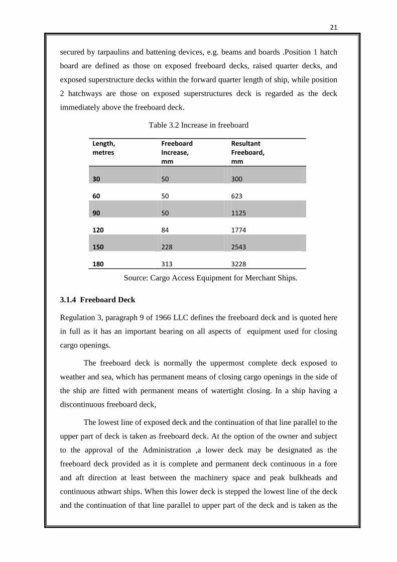
21
secured by tarpaulins and battening devices, e.g. beams and boards .Position 1 hatch
board are defined as those on exposed freeboard decks, raised quarter decks, and
exposed superstructure decks within the forward quarter length of ship, while position
2 hatchways are those on exposed superstructures deck is regarded as the deck
immediately above the freeboard deck.
Table 3.2 Increase in freeboard
Length, metres
Freeboard Increase, mm
Resultant Freeboard, mm
30 50 300
60 50 623
90 50 1125
120 84 1774
150 228 2543
180 313 3228
Source: Cargo Access Equipment for Merchant Ships.
3.1.4 Freeboard Deck
Regulation 3, paragraph 9 of 1966 LLC defines the freeboard deck and is quoted here
in full as it has an important bearing on all aspects of equipment used for closing
cargo openings.
The freeboard deck is normally the uppermost complete deck exposed to
weather and sea, which has permanent means of closing cargo openings in the side of
the ship are fitted with permanent means of watertight closing. In a ship having a
discontinuous freeboard deck,
The lowest line of exposed deck and the continuation of that line parallel to the
upper part of deck is taken as freeboard deck. At the option of the owner and subject
to the approval of the Administration ,a lower deck may be designated as the
freeboard deck provided as it is complete and permanent deck continuous in a fore
and aft direction at least between the machinery space and peak bulkheads and
continuous athwart ships. When this lower deck is stepped the lowest line of the deck
and the continuation of that line parallel to upper part of the deck and is taken as the
22
freeboard deck. When a lower deck is designated the freeboard deck, the part of hull
which extend above the freeboard deck is treated as superstructure so far as concerns
the application of the conditions of the assignment and the calculation of freeboard. It
is from this deck that the freeboard is calculated.
It should be noted that the requirement for a lower deck to complete and
permanent in order to be designated the freeboard deck, does not mean that any
openings need to be weather tight, only that the structure of a deck is present. Tween-
deck hatches may be of steel or wood, but are only required to be watertight if fitted
to deep tanks or compartments containing water ballast.
The ‘Administrations’ referred to include the Department of Trade in the
United Kingdom, the us coast guard in the united states and equivalent in other
countries.
3.1.5 Weather-Tightness and Water-Tightness
Regulation of the 1966 LLC which covers the mean for securing weather-tightness of
steel weather-tight covers states that ‘The means for securing and maintaining
weather-tightness shall be to the satisfaction of the Administration. The arrangement
shall ensure that the tightness can be maintained ain any sea conditions, and for this
purpose test for tightness shall be required at initial survey ,and may be required at
periodical survey and at annual inspections or at more frequent intervals.
Regulation defines ‘weather-tight’ as meaning that water will not penetrate
into the ship in any conditions. ‘Weather-tight’ is not defined into 1996 LLC but is
generally regarded as higher standard than weather-tight.it is usually taken to require
the closure to be capable of preventing the passage of water through the structure in
any direction, under the head of ships margin line, which is line drawn at least 76 mm
in below the upper surface of bulkhead deck at the side of ship.
In practice the hatch covers of B-60 and B-100 ships must be of steel and
made weather-tight by means of special gasket devices. Less commonly, hatch may
be made weather-tight by means of tarpaulins and battening devices over wooden or
portable steel pontoon covers.
3.1.6 Statutory Regulations
The 1966 load line convention came into force in 1968 after it had been ratified by
required number of maritime nations. In UK the convention was brought into the
23
force by the 1967 Merchant shipping Act from which the merchant shipping (load
line) rules 1968 were made the rules for the constructions of ship laid down by
Lloyds register of shipping are consistent with the convention, as are those of other C
classification societies.
3.2 GENERAL CONSIDERATIONS FOR ACCESS EQUIPMENT
3.2.1 Coaming height
Minimum coaming height, derived from the 1966 LLC, is laid down by Classification
Societies. Height are measured above the upper surface of the deck, and any sheathing
that may be fitted, and for hatchway closed by portable covers secured water tight by
tarpaulins and battening devices, they must not be less than:
600 mm (23.5 in) for Position 1;
450 mm (17.5 in) for Position 2,
Coaming of hatchways closed by steel covers fitted with direct securing
arrangements are usually as indicated above, taking into account any sheer or camber
when assessing minimum height. They may, however, be lower, or even omitted
entirely, if the safety of the ship is not impaired by doing so, provided the
Administration of the country concerned consents.
The scantling and securing arrangements of flush hatch covers or those having
less than standard height coamings are treated as special cases. Such arrangements
have been approved in the past. Dock safety regulations generally require a minimum
coaming height of about 760 mm (2 ft 6 in), otherwise additional fencing must be
fitted to prevent personnel falling through the hatchway.
It is rare for ship to have coamings of lower height than those stipulated,
unless they are completely flush. Flush weather decks are required in a variety of
circumstances. For instance, vehicles, wheeled cargo, or containers must sometime be
stowed over the full deck area including the hatch covers, and clear decks for
recreation are desirable in passenger ships. Satisfying the flood ability requirement for
B-100 and B-60 ships may result in coaming being increased in height on such ships
to meet loadline and subdivision regulation.
24
In practice one of the principal determinants of coaming height is the operation
of the hatch cover. Other types that are affected in this way are rolling stowing covers
where the drum height must be sufficient to allow the stow covers to fit between the
drum axis and the deck and single pull covers whose panels stow in an upright
position standing clear of the deck.
The coaming may also be increased in height to obtain additional cargo
capacity. As a result of these considerations, the majority of the ships have in the
range 1.0-1.8 m. It is useful if crew and stevedores can see readily into the holds
during port operations. Thus if the coaming is higher than about 1.4 m, a step or a
narrow platform should be fitted at the suitable height. While the top of the coaming
is nearly always at the same level on all its sides, it need not be parallel with the deck.
Neither is it essential that the coaming plates be vertical, if by sloping them inwards, a
larger opening at deck level can be obtained.
Another factor influencing coaming height is the nature of particular deck
cargoes. Packaged lumber, for example, is usually stowed abreast hatchways until it
reaches the height of the hatch cover top, when it is distributed over its whole width of
the ship. Lumber is usually banded into packages, each 660 mm high, which are
stowed with a 25 mm batten between them. Coamings should therefore be designed
with a height from deck to hatch cover top which is a multiple of 685 mm (27 in). In
heavy lift cargo liners, the coaming height and bulwark height are often the same so
that awkward loads like barges may be easily supported across the entire ship.
In some ship the internal volume bounded by the coamings needs to be a
greater proportion of the total hold volume than the minimum 600 mm coaming
height allows. In the past certain ships engaged in the grain trade were required to
have coamings enclosing 4 percent of the total hold volume to allow for settling, but
this requirement have now been suppressed by the provisions of the Safety of Life at
Sea Conventions 1974(SOLAS 74). These new provisions do not stipulate a minimum
or maximum coaming volume, although it may be necessary to arrange a coaming
height in excess of 600 mm in a particular ship so as to meet the stability requirements
for the carriage or grain. These assume that the cargo ships in to void spaces below
side decks, so producing a heeling moment which depends on the resulting ‘free
surface’ of the grain.
25
3.2.2 Cover Stowage
Where a designer is attempting to obtain the largest possible hatchway openings, the
question of the hatch cover stowage is especially important. The width of the stowage
space is fixed by the hatchway width if the covers are stowed at the end of the
hatchway, but the height and length of the space can be varied. If the hatchways are to
be the longest possible in a given deck length, the length of the stowage space must be
kept to a minimum; this can be accomplished in a various ways depending on the type
of hatch cover employed. No special stowage space is required for simple pontoon
covers since these are usually stowed on adjacent hatch covers or on the quayside
when the hatch is open. Alternatively side rolling covers may be used if the hatchway
is not too wide in relation to the ships breadth.
3.2.3 Deck Openings
As deck opening becomes larger, the problem of ensuring adequate hull strength
becomes more complex. The necessary longitudinal strength of the hull girder can be
readily achieved, even for ships with hatch widths 80 percent of the breadth of the
ship, by the use of high tensile steels. But the provision of the adequate torsion
strength may require very detailed design and stress analysis, since the torsional
deflection of a ship with large hatchways give rise to high stress concentration at the
corners of the openings and to deformation of the hatchway.
26
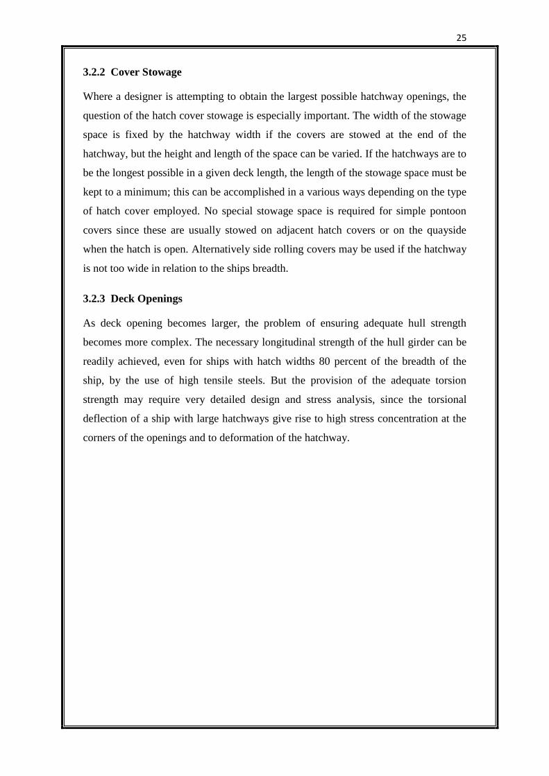
Figure 3.1 (a) Rounded deck opening with coaming
(b) Coaming plate following deck opening
Source: Cargo Access Equipment for Merchant Ships.
To avoid high stress concentration in deck plating, the corners of deck
openings should be elliptical or parabolic. As the corners of the hatch covers are
usually rectangular, provision has to be made to accommodate the hatch coaming.
This can be done in two ways: either a square coaming can be built with the rounded
deck plating protruding into the coaming space shown in fig3.1 (a) and (b) or the
coaming can follow the shape of the deck opening with a filling-in plate welded to its
top. In both cases the clear opening for rectangular cargoes like containers will be
appreciably smaller than the maximum dimensions to the inside of the coamings.
3.2.4 Drainage
As mentioned earlier, an important function of access equipment is to prevent water
entering the ship through the openings in its hull. If the hull is flexing in heavy
weather, it is almost inevitable that some water will penetrate the seals of closing
devices, especially if they are worn. Thus there must be a second line of defence, such
as drains, for removing any water before it can damage the cargo.
Drainage facilities must be built into all terms access equipment. Here water
which seeps past the peripheral seal of a hatch cover runs along a channel and is
discharged onto the weather deck through a hole in the coaming. Where the drain is
below the freeboard deck, as in flush weather deck covers, it must be connected to the
bilge, or overboard via a scupper and non return valve.
27
It is also necessary to provide drainage for the vehicle deck in Ro-Ro vessels.
Any scupper which drains a space within an intact superstructure on the free board
deck (usually the main vehicle deck) is led overboard through a pipe fitted with a
screw-down non return valve having open/shut indicators and capable of being
operated from accessible positions above the freeboard deck. Alternatively the
scupper may be led down to the bilges or to a drain tank. In an enclosed tween deck
space with a continues centre-line casing, additional scuppers must be installed
adjacent to the casing on the main vehicle deck. Where the inboard end of a deck
scupper would be below the load waterline at an angle of heel less than 15 degree, it
should be led to a separate drain tank, which may be pumped overboard.
3.3 SPECIFIC DESIGN REQUIREMENTS FOR HATCH COVERS
3.3.1 Hatch Covers
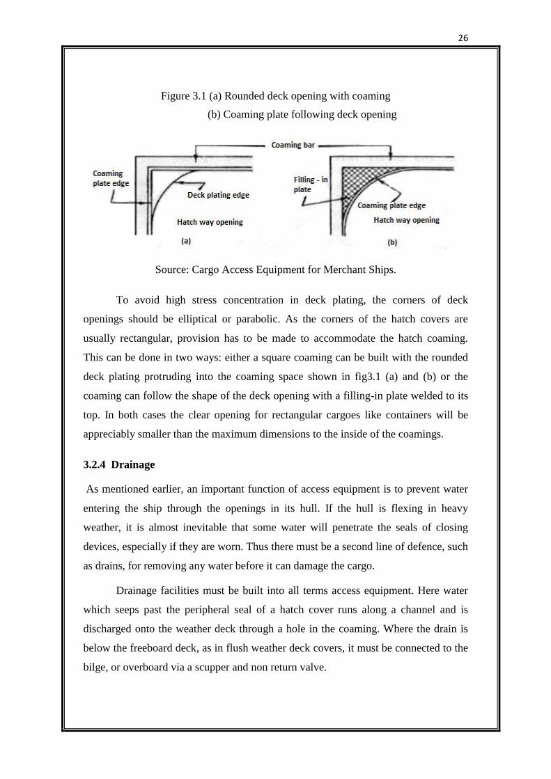
The hatch cover structure consists in essence of steel beams or grinders spanning the
shorter hatchway dimension, plated over on top completed by steel side and end
plates. The top plate provides the top flange of the beams and grinders. For the
simpler types of hatch cover panel, e.g. pontoon or single pull, the design and analysis
assume a uniformly loaded simply supported beam as shown in the fig 3.2.
Figure 3.2 Beam is treated as a uniformly loaded simply supported structure
Source: Cargo Access Equipment for Merchant Ships.
3.3.1.1 Structural regulations
The construction of exposed hatch covers is governed by regulations 14 to 16 of the
1966 Load line convention (1966 LLC). Regulation stipulates that exposed coamings
and hatchway covers above the superstructure deck shall comply with the
requirements of the appropriate national administration, which means in effect, that
28
such equipments must be design in accordance with the current practice of the
administration.
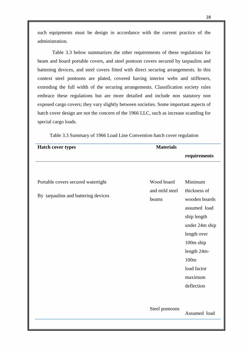
Table 3.3 below summarizes the other requirements of these regulations for
beam and board portable covers, and steel pontoon covers secured by tarpaulins and
battening devices, and steel covers fitted with direct securing arrangements. In this
context steel pontoons are plated, covered having interior webs and stiffeners,
extending the full width of the securing arrangements. Classification society rules
embrace these regulations but are more detailed and include non statutory non
exposed cargo covers; they vary slightly between societies. Some important aspects of
hatch cover design are not the concern of the 1966 LLC, such as increase scantling for
special cargo loads.
Table 3.3 Summary of 1966 Load Line Convention hatch cover regulation
Hatch cover types Materials
requirements
Portable covers secured watertight
By tarpaulins and battering devices
Wood board
and mild steel
beams
Steel pontoons
Minimum
thickness of
wooden boards
assumed load
ship length
under 24m ship
length over
100m ship
length 24m-
100m
load factor
maximum
deflection
Assumed load
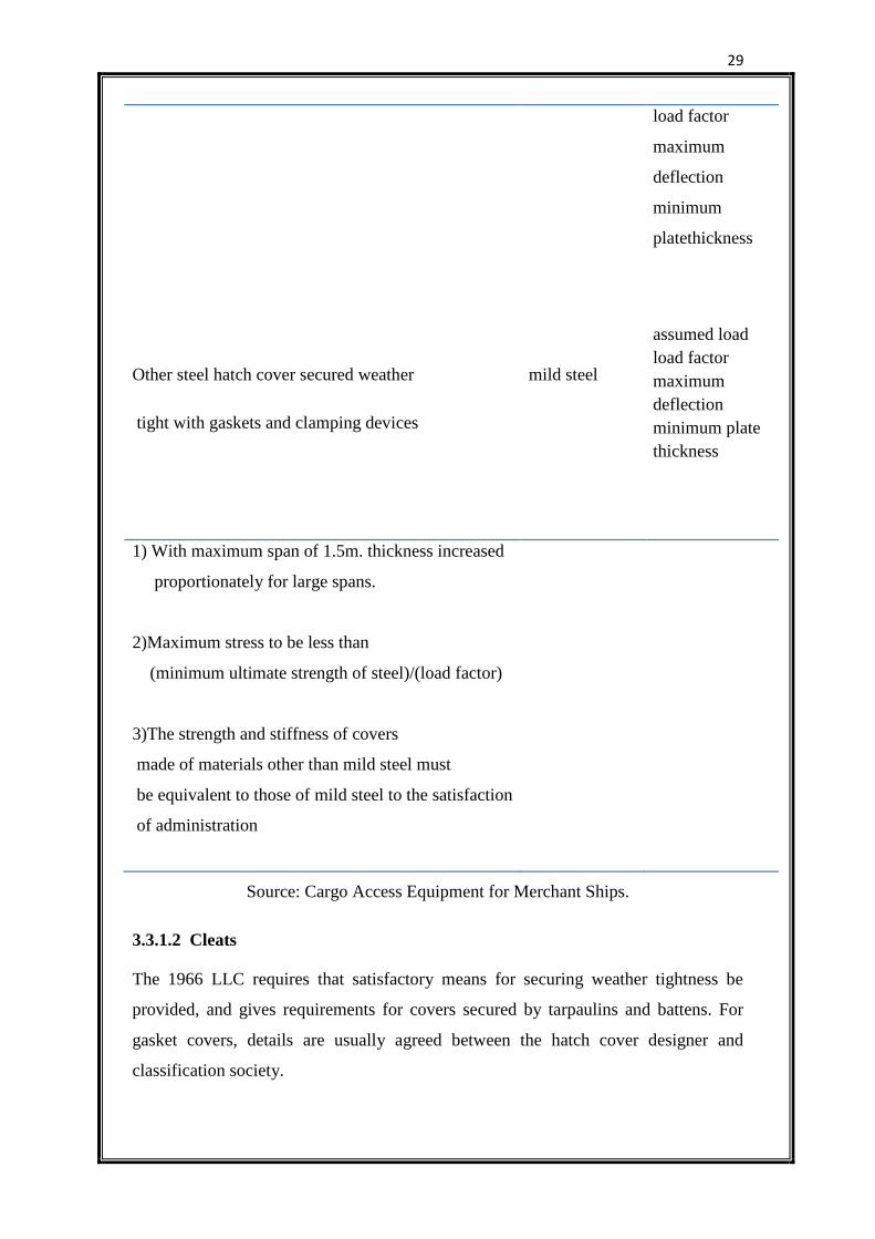
29
Other steel hatch cover secured weather
tight with gaskets and clamping devices
mild steel
load factor
maximum
deflection
minimum
platethickness
assumed load
load factor
maximum
deflection
minimum plate
thickness
1) With maximum span of 1.5m. thickness increased
proportionately for large spans.
2)Maximum stress to be less than
(minimum ultimate strength of steel)/(load factor)
3)The strength and stiffness of covers
made of materials other than mild steel must
be equivalent to those of mild steel to the satisfaction
of administration
Source: Cargo Access Equipment for Merchant Ships.
3.3.1.2 Cleats
The 1966 LLC requires that satisfactory means for securing weather tightness be
provided, and gives requirements for covers secured by tarpaulins and battens. For
gasket covers, details are usually agreed between the hatch cover designer and
classification society.
30
An important aspect of the gasket type securing arrangement, whatever its
form is that the pressure between the sealing gaskets and compression bars is correctly
maintained. Manual cleats are often over tightened despite the steel to steel contact of
the cover skirt plates on the coaming bar, with the result that gasket. Life is severely
shortened. This problem is overcome by the introduction of resilient and quick acting
cleats which means that the correct sealing pressure is consistently and uniformly
applied. Cleats on steel covers are generally spaced about 1.5-2 m apart, closer
adjacent to the corners, and no more than 0.6 m apart for wooden covers. With the
advent of larger and heavier hatch covers, the classification societies have, in some
cases, approved covers with greater than usual cleat spacing.
3.3.1.3 Loads
The hatch loading laid down by the 1966 LLC and summarized in table shown take
account of the forces exerted on exposed covers by heavy seas breaking over the deck.
Once again however, these are mandatory minimum values and the classification
societies may require that they are increased in certain cases. Thus for hatch covers on
which deck cargoes are rarely if ever carried, the loading laid down are adequate,
typically 1.75 tonnes/ . This is equivalent to the cargo stowed 2.45 m high at 1.39
/tonnes. Loading for the covers in the foremost quarter of the ship’s length may be
increased to counter the severe sea water forces likely to be experienced in this region.
3.3.1.4 Scantling
Minimum scantling (thickness and dimensions of steel plating and stiffeners) and load
factors for steel covers respecified in the 1966 LLC, so that the load factor multiplied
by the maximum stress in the covers is less than or equal to the minimum ultimate
strength of the steel. Corresponding minimum scantling depending on loading are
given in classification society rules, alternatively direct calculations of required
structural strength may be made using maximum design stress levels.
Table 3.4 below shows the requirements of Lloyd’s Register with respect to
steel hatch covers or other access equipments constructed of grade A mild steel
having a minimum ultimate tensile strength of 4100Kgf cm square.
31
Table 3.4 Access equipment strength calculations
Factor Weather deck Tween-deck
Maximum bending stress,
kgf/cm square
965 1200
Maximum shear stress,
kgf/cm square
700 700
Maximum deflection 0.0028 * span 0.0035*span
Source: Cargo Access Equipment for Merchant Ships.
The top plate of a typical hatch cover panel may be from 6-13 mm thick
depending on the spacing of the beams (generally, thickness=spacing/100). This plate
is stiffened by beams spanning the hatch cover, usually fabricated ‘tee’ beams having
a depth of about 4 percentage of the span and spaced 500-1000 mm apart. The panel is
completely by side and end plates which may be from 8.20 mm thick.
3.3.1.5 Deformation
As the ship become larger and hatchways take up a greater percentage of the deck
area, so the question of hatchway deformation becomes more important. Traditionally
ships have fairly small hatchways and so have derived a considerable amount of their
strength from their decks. As hatchways have increased in width, so the deck’
contribution to the longitudinal and the torsional strength of the hull girder has
declined, being limited to the strips of deck outboard of the coaming and between the
hatches. A ship with hatchways more than 70 percentage of the beam in width has
approximately half the torsional rigidity of a similar ship with hatchways which are
only 40 percentage of the ship’s beam. Compensation in the form of thickened plating
and/or box girders may be required.
Fig 3.3 indicates the extent of hatchway deformation that may be encountered
in a large bulk carrier loaded in alternate holds. Although the deformation is not
excessively large and is not permanent, they can be sufficient to allow sea water to
enter and parts of the hatch cover to fracture.
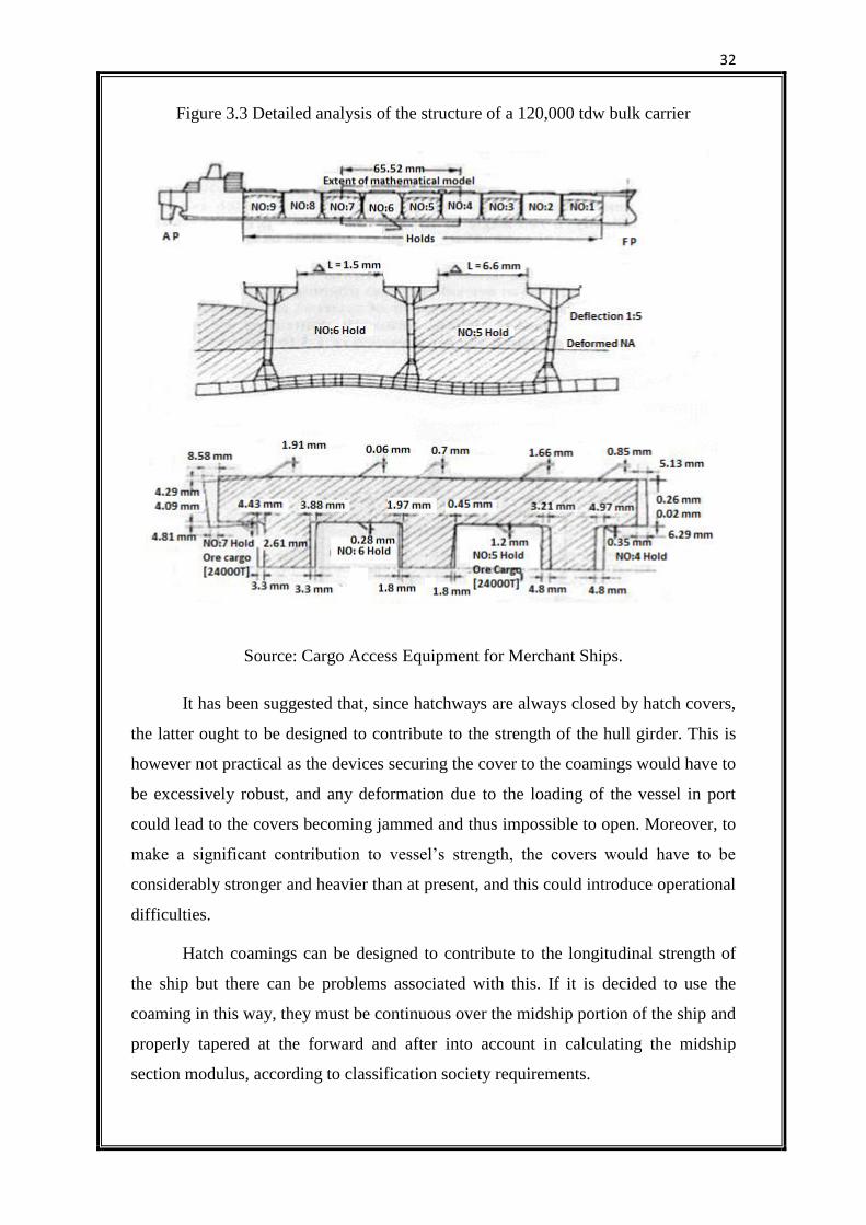
32
Figure 3.3 Detailed analysis of the structure of a 120,000 tdw bulk carrier
Source: Cargo Access Equipment for Merchant Ships.
It has been suggested that, since hatchways are always closed by hatch covers,
the latter ought to be designed to contribute to the strength of the hull girder. This is
however not practical as the devices securing the cover to the coamings would have to
be excessively robust, and any deformation due to the loading of the vessel in port
could lead to the covers becoming jammed and thus impossible to open. Moreover, to
make a significant contribution to vessel’s strength, the covers would have to be
considerably stronger and heavier than at present, and this could introduce operational
difficulties.
Hatch coamings can be designed to contribute to the longitudinal strength of
the ship but there can be problems associated with this. If it is decided to use the
coaming in this way, they must be continuous over the midship portion of the ship and
properly tapered at the forward and after into account in calculating the midship
section modulus, according to classification society requirements.
33
Longitudinal deformation of the top of the coaming is due to the hogging or
sagging of the vessel. It depends on hatchway length and may be as much as 7-8 mm
at each end. Longitudinal deformation is compensated for by fitting at the ends of the
hatch cover with wide gaskets whose rubber absorbs the relative movement of the
compression bars as the sip works. Hatch end cleats must allow such movements,
which would otherwise be taken up at the cross joint with attendant risk of leakage.
Steel to steel contact is must. The purpose of this is to prevent the over compression
of the gaskets. However, it gives rise to a frictional force whose magnitude depends
on the pressure of the cover on the coaming bar and their relative movement.
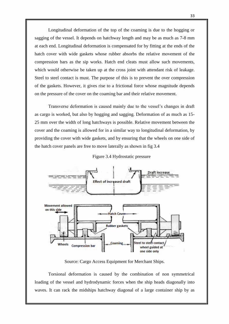
Transverse deformation is caused mainly due to the vessel’s changes in draft
as cargo is worked, but also by hogging and sagging. Deformation of as much as 15-
25 mm over the width of long hatchways is possible. Relative movement between the
cover and the coaming is allowed for in a similar way to longitudinal deformation, by
providing the cover with wide gaskets, and by ensuring that the wheels on one side of
the hatch cover panels are free to move laterally as shown in fig 3.4
Figure 3.4 Hydrostatic pressure
Source: Cargo Access Equipment for Merchant Ships.
Torsional deformation is caused by the combination of non symmetrical
loading of the vessel and hydrodynamic forces when the ship heads diagonally into
waves. It can rack the midships hatchway diagonal of a large container ship by as
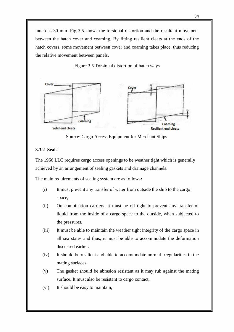
34
much as 30 mm. Fig 3.5 shows the torsional distortion and the resultant movement
between the hatch cover and coaming. By fitting resilient cleats at the ends of the
hatch covers, some movement between cover and coaming takes place, thus reducing
the relative movement between panels.
Figure 3.5 Torsional distortion of hatch ways
Source: Cargo Access Equipment for Merchant Ships.
3.3.2 Seals
The 1966 LLC requires cargo access openings to be weather tight which is generally
achieved by an arrangement of sealing gaskets and drainage channels.
The main requirements of sealing system are as follows:
(i) It must prevent any transfer of water from outside the ship to the cargo
space,
(ii) On combination carriers, it must be oil tight to prevent any transfer of
liquid from the inside of a cargo space to the outside, when subjected to
the pressures.
(iii) It must be able to maintain the weather tight integrity of the cargo space in
all sea states and thus, it must be able to accommodate the deformation
discussed earlier.
(iv) It should be resilient and able to accommodate normal irregularities in the
mating surfaces,
(v) The gasket should be abrasion resistant as it may rub against the mating
surface. It must also be resistant to cargo contact,
(vi) It should be easy to maintain,
35
(vii) It should retain all the above properties throughout a long service life,
exposed to climate extremes.
3.3.2.1 Gaskets material
Gaskets material must be of a suitable quality; it should not harden excessively when
subjected to neither sub-zero temperature nor soften in tropical conditions.
Particularly important in this respect are gaskets fitted to refrigerated vessels.
Most gaskets used for seals on dry cargo ships are of natural, synthetic or
neoprene rubber, while combination carriers requires a nitrile composition, resistant to
chemical attack by oil. In general neoprene synthetics have good heat, ageing, weather
and flame resistance, but only moderate oil and chemical resistance but worse cold
temperature properties. General construction of seal steel work, welding and painting
needs careful attention.
3.3.2.2 Compression bars
The usual arrangement of compression bars is shown. It is of rectangular section mild
steel welded to the coaming bar. After several years of service, these bars can become
badly corroded and require replacing. Moreover, they may then have sharp corners
which press into the gaskets so that the rubber takes on a permanent set earlier in its
life than would be the case for a sealing arrangement employing either a round
compression bar, as shown or rectangular one with rounded corners. The latter
produces an element of ‘knife edge’ loading which gives the good seal with the
rubber. When such compression bars are fitted, they are often of stainless steel, which,
although initially expensive, often worthwhile as it is not usually necessary to replace
the bar during the life of the corners
3.4 CONSTRUCTION MATERIALS
In general, Grade A mild steel is used for the construction of all cargo access
equipment. Grade A is the ‘ordinary’ mild steel used for most ship building purposes.
Certain application requires Grades D and E steel. Grade D is notch-tough steel with a
chemical composition largely chosen by the steel producer provided that it retains
good weldability. Grade E steel is the highest grade and is also notch-tough but its
manufacture and composition are strictly controlled. Grades D and E steel are
specified for coaming bars on refrigerated ships where low temperature brittle fracture
36
must be guarded against. As these steels have low corrosion resistances, special
coating, e.g. epoxies, are often used on the underside of hatch covers where sweating
can cause accelerated corrosion. Other materials such as higher tensile steel and
aluminium are acceptable to the Classification Societies.
3.4.1 Higher Tensile Steel (HTS)
If the stress level within a structure were the only factor governing its scantlings, the
use of higher tensile steel instead of mild steel would result in weight savings of up to
15 percent. However stress is not the only governing factor. Deflection, minimum
thickness, ease of construction, initial and maintenance costs must all be taken into
account. Higher tensile steel (HTS) can sometimes be used for the beams of hatch
covers, with their top plates made from mild steel. This reduces the weight of the
covers, without incurring the extra cost of using all HTS construction. Thus, HTS is
sometimes used on hatch covers where, by reducing the cover weight slightly, it may
be possible to install less powerful operating mechanism. Construction entirely in
HTS is sometimes used in pontoon covers for container ships, to keep their weight
below the maximum lifting capacity of container cranes.
3.4.2 Aluminium
Aluminium structures can be 55-60 percent lighter than equivalent mild steel
structures. Most of the problems associated with higher tensile steel are not present
with aluminium. Since it is not as strong as steel, thickness have to be increased,
thereby alleviating problems associated with minimum regulatory deflection, buckling
etc., unless the design is such that deflection is significant. Welding aluminium does
however require special skills and equipment. Corrosion is less of a problem if the
correct grade of material is used and if precaution are taken where steel and
aluminium meet, e.g. at coamings. The spacing of stiffeners can be increased in an
aluminium structures this has the added advantage that the number of stiffeners and
hence the weight and cost of the structure can be further reduced. The major
disadvantage of aluminium is that a suitable grade of material for access equipment
costs approximately eight times as much per tonne as mild steel, with the overall
effect of increasing the cost of the cover by upto three times.
Aluminium covers have been fitted to deep tanks because they are so much
lighter. Since deep tank covers are often made in one piece, aluminium covers are
37
easier to handle without power assistance. Aluminium single pull weather deck covers
have occasionally been fitted in the past, sometimes experimentally. Aluminium can
be used for Ro-Ro vessel access equipment but it is usually limited to small ramps and
car decks. It is less resistant to fire damage than steel.
3.4.3 Glass Reinforced Plastic (GRP)
GRP structures are light but the modulus of elasticity of GRP is only 7 percentages of
that of mid steel and excessive deflection is a problem which invariably accompanies
its use. Additional stiffening is thus necessary, making the structure heavier and more
expensive to manufacturer. For this reason GRP has not as yet found wide application
in the construction of cargo access equipment, although development work is in
progress. GRP in ‘sandwich’ construction could be particularly suitable for covers in
refrigerated ships because insulation can be built into them during the manufacturing
process at very little extra cost, whereas the present system of insulating steel covers
is expensive and time consuming.
3.4.4 Wood
Wooden covers no longer supplied to weather decks of new cargo ships, although on
rare occasions, they are fitted in tween decks. Classification society rules lay down
scantling for beam and boards covers because of LLC requirements; in practice they
care now mainly for the benefit of repair to older ships.
38
CHAPTER 4 - OPERATIONAL AND SAFETY ASPECTS
4.1 BASIC ADVICE
There are procedures which will help to keep ship’s hatch covers in good condition.
The following advice can be considered best practice.
4.1.1 Always
Carry out regular examination of the hatch covers, hatch beams and coamings
to identify:
o General levels of corrosion (check with your classification society for
corrosion allowances);
o localised corrosion at welded connections (grooving);
o Cracks in joints and weld metal;
o Permanent distortion of plating and stiffeners;
Call a Class Surveyor and carry out repairs as soon as possible when there are:
o Indications of excessive corrosion e.g. holes or local buckling of the
top plate;
o Cracks in main structural joints;
o Areas of significant indentation, other than localised mechanical
damage;
Be particularly vigilant after heavy weather;
Rectify any steel-to-steel fault before renewal of rubber packing. Renewal will
not be effective if steel-to-steel contact points are defective, and expensive
rubber packing will be ruined after only a few months of use;
Replace missing or damaged hatch gaskets (rubber packing) immediately. The
minimum length of replaced gasket should be one metre;
Keep hatch coaming tops clean and the double drainage channels free of
obstructions. (Open hatch covers to clean coaming tops and the double
drainage channels after loading bulk cargo through grain or cement ports);
Keep cleats and wedges in serviceable condition and correctly adjusted;
Keep hauling wires and chains adjusted correctly;
Attach locking pins and chains to open doors and hatches;
39
Keep wheels, cleats, hinge pins, haul wires, and chain tension equipment well-
greased;
Test hydraulic oil regularly for contamination and deterioration;
Keep hydraulic systems oil tight;
Ensure the oil tank of the hydraulic system is kept filled to the operating level
and with the correct oil;
Clean up oil spills. If the leak cannot be stopped immediately, construct a
save-all to contain the oil and empty it regularly;
Engage tween deck hatch cover cleats when the panels are closed;
Give notice that maintenance is being performed so that no one tries to
open/close the hatch;
Remember that continuing and regular maintenance of hatches is more
effective and less expensive than sporadic inspection and major repair.
4.1.2 Never
Treat temporary repairs as if these were permanent. The strength of the cover
and ultimately the ship will depend on the quality of repairs carried out;
Ignore serious corrosion, cracking or distortion in the covers and supports.
These are signs of weakness and are potentially hazardous;
Allow grooves to form in the coaming top, especially where the hatch side or
end panel rests when the hatch is closed;
Apply petroleum-based grease or paint to rubber packing;
Remove the rubber ball from a non-return drain valve;
Use anything other than the recommended hydraulic oil;
Leave cleats unfastened when proceeding to sea;
Attempt to open or close any hatch that has a load or cargo on it;
Open hatch covers at sea unless absolutely essential;
Leave open covers unattended when at sea;
Tighten down the cleats so that the hatch cover is unable to move on the
coaming top.
40
4.2 MONITORING AND INSPECTION
Hatch covers and their fittings should be inspected at the end of every cargo voyage
and all findings recorded. Inspections should be planned and held in time for repairs
to be completed before the next cargo voyage. Empty cargo spaces of all cargo and
combustible material if welding torches are used.
4.2.1 Inspect and Check:
Condition, Covers and coamings should be well painted and free from
significant corrosion, cracks and distortion. During an inspection look for:
o Holes and permanent distortion in the plating
o Distortion of beams and/or stiffeners on the underside of the top plate
o Corrosion around welded connections of beams or stiffeners
o cracking of connecting joints and welds
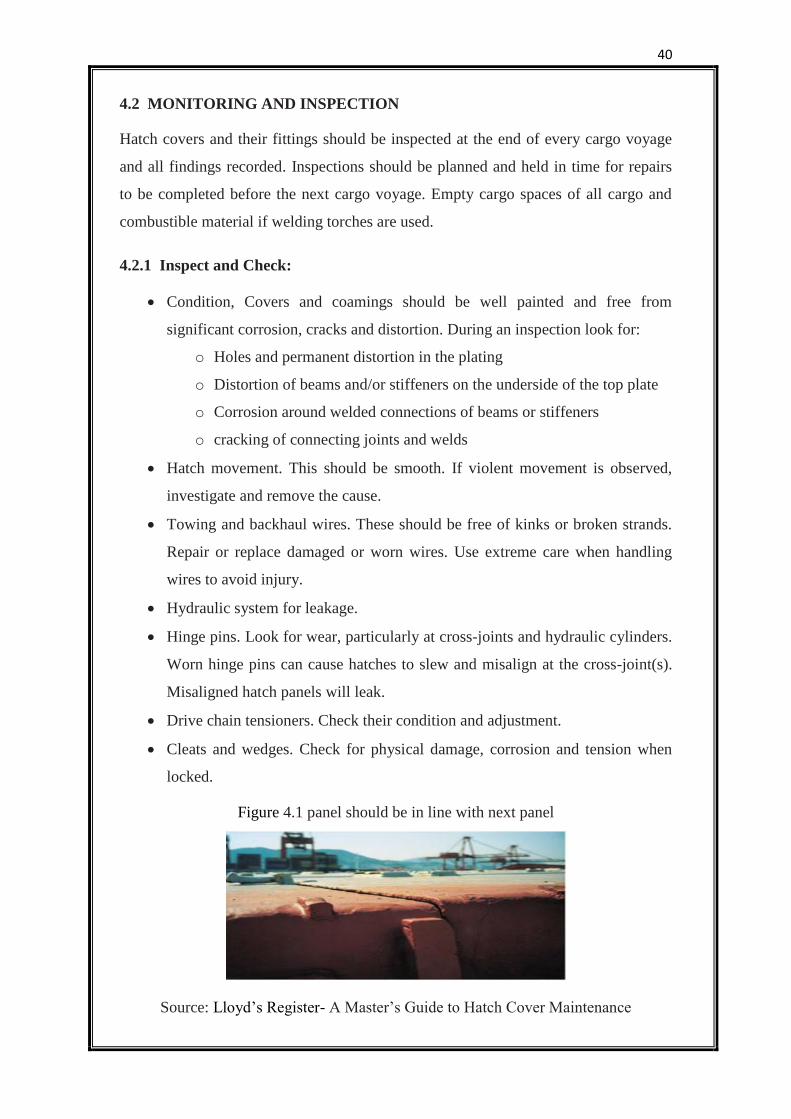
Hatch movement. This should be smooth. If violent movement is observed,
investigate and remove the cause.
Towing and backhaul wires. These should be free of kinks or broken strands.
Repair or replace damaged or worn wires. Use extreme care when handling
wires to avoid injury.
Hydraulic system for leakage.
Hinge pins. Look for wear, particularly at cross-joints and hydraulic cylinders.
Worn hinge pins can cause hatches to slew and misalign at the cross-joint(s).
Misaligned hatch panels will leak.
Drive chain tensioners. Check their condition and adjustment.
Cleats and wedges. Check for physical damage, corrosion and tension when
locked.
Figure 4.1 panel should be in line with next panel
Source: Lloyd’s Register- A Master’s Guide to Hatch Cover Maintenance
41
4.2.2 Drive Chains; Check their Length
Drive chains and associated equipment are fitted in pairs, opposite one another. The
side towing chains, sprockets and hydraulic cylinders on opposite sides should match.
Adjust the tension of chains between panels so that the chains on both sides are
exactly the same length. Do this by removing or adding chain links. If the entire
length of chain needs to be replaced, then replace the chains on both sides at the same
time. Always consult the hatch cover manufacturer for details of chain length. As a
rule, chain sag, measured from the assumed horizontal at mid-point along the chain,
should be a fist wide.
4.2.3 Steel Landing Pads; Check for Wear
Worn landing pads will damage hatch gaskets and cause hatch leakage. When newly
fitted and closed in the sea position, the top plates of adjacent hatch panels should be
level. Any deviation from level is an indication of landing pad wear or permanent
distortion. If noted, investigate fully and repair immediately.
4.2.4 End Stop Pads; Check for Damage
End stop pads prevent hatch panels from overrunning when hatches are fully open.
Look for physical damage.
4.2.5 Hatch Wheels; Check for Alignment
Hatch wheels should align squarely with the hatch track way. If the wheel axle is
worn the wheel will loll. If it does, repair immediately.
4.2.6 Rubber Seals; Check for Elasticity, Mechanical Damage and Permanent
Deformation
When hatches are opened, rubber seals should regain their original shape. If they do
not, check for ageing. Permanent deformation should not exceed 75 percent of the
design compression.
4.2.7 Locking Devices and Hydraulic Cut-Outs; Check that they Operate
Locking devices are often pins or hooks, these should engage when the hatch is open.
Look for physical damage, rusting and seizure. Hydraulic cut-outs should move
freely.
42
4.2.8 Spares
Rubber packing and adhesive has a limited shelf life, so check the date stamp and
discard if beyond the use-by date. There should be sufficient spare parts (cleats,
wedges and gaskets) to complete planned routine maintenance. Always use
manufacturers’ approved spare parts.
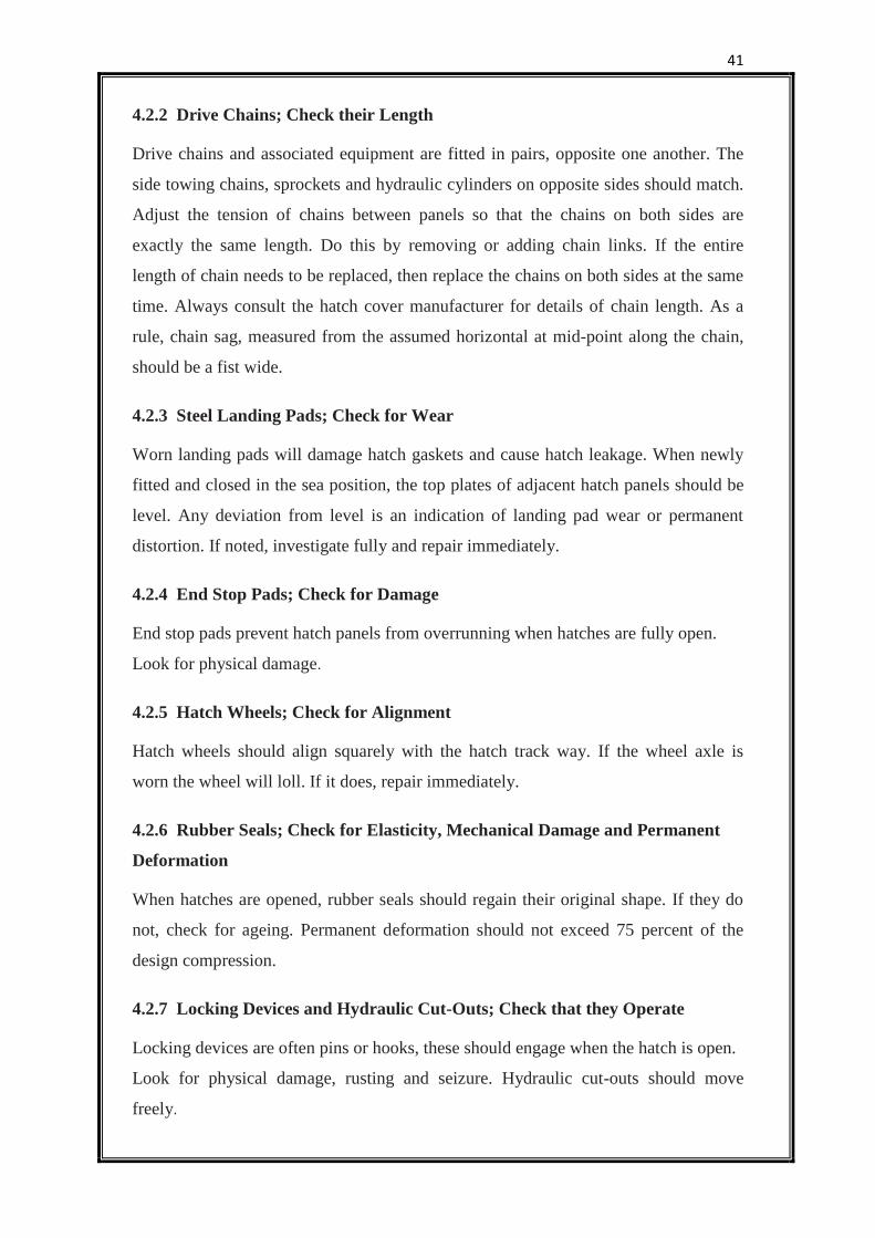
4.3 HEAVY WEATHER PRECAUTIONS
The following precautions should be taken if rough or heavy weather or when high
swells are expected or when it is likely that water will be shipped on deck.
4.3.1 Prior To Rough Weather:
Check that hatch cleats are properly secured and adjusted. In rough weather,
hulls are subjected to high racking forces, so it is essential that hatch covers
are held in place but allowed to flex.
Check that all drain valves are operating correctly and that they are open.
Drain valves are the last defence against water entering the cargo space. The
drainage system will be needed during heavy weather, so it must be fully
operational.
As a precaution, briefly pressurise the hydraulic system to ensure that it is
fully charged and that the piping is filled with oil. This has two benefits, first,
it prevents the possibility of seawater entering loose couplings or seals, and
secondly, it eliminates any creep which may have occurred.
4.3.2 After Rough Weather:
Inspect all cleats, drain valves, guides and hydraulic components for damage.
If hydraulic components have been damaged, do not attempt to open the
covers. The emergency opening procedure should be followed until the
hydraulic components have been checked and tested.
Check hatch covers for buckling or distortion.
When opening the hatch covers check for uneven movement and any unusual
noises that may indicate damage.
Check all grease points and re-grease.
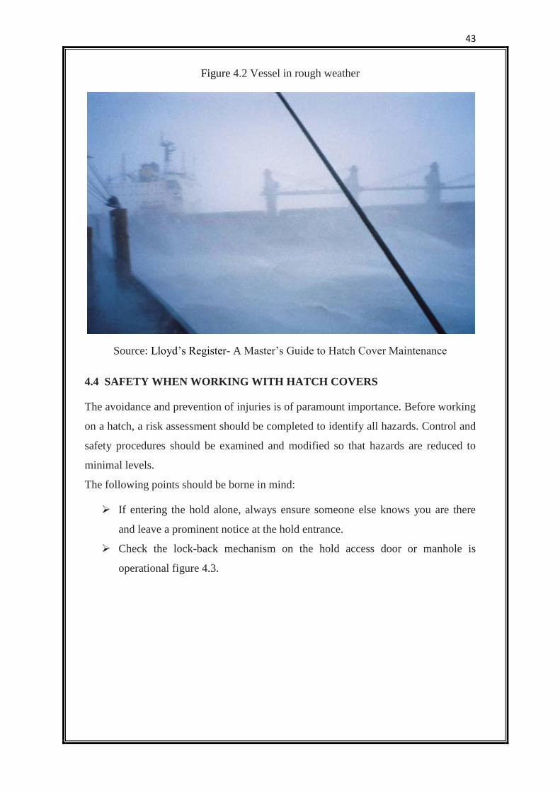
43
Figure 4.2 Vessel in rough weather
Source: Lloyd’s Register- A Master’s Guide to Hatch Cover Maintenance
4.4 SAFETY WHEN WORKING WITH HATCH COVERS
The avoidance and prevention of injuries is of paramount importance. Before working
on a hatch, a risk assessment should be completed to identify all hazards. Control and
safety procedures should be examined and modified so that hazards are reduced to
minimal levels.
The following points should be borne in mind:
If entering the hold alone, always ensure someone else knows you are there
and leave a prominent notice at the hold entrance.
Check the lock-back mechanism on the hold access door or manhole is
operational figure 4.3.
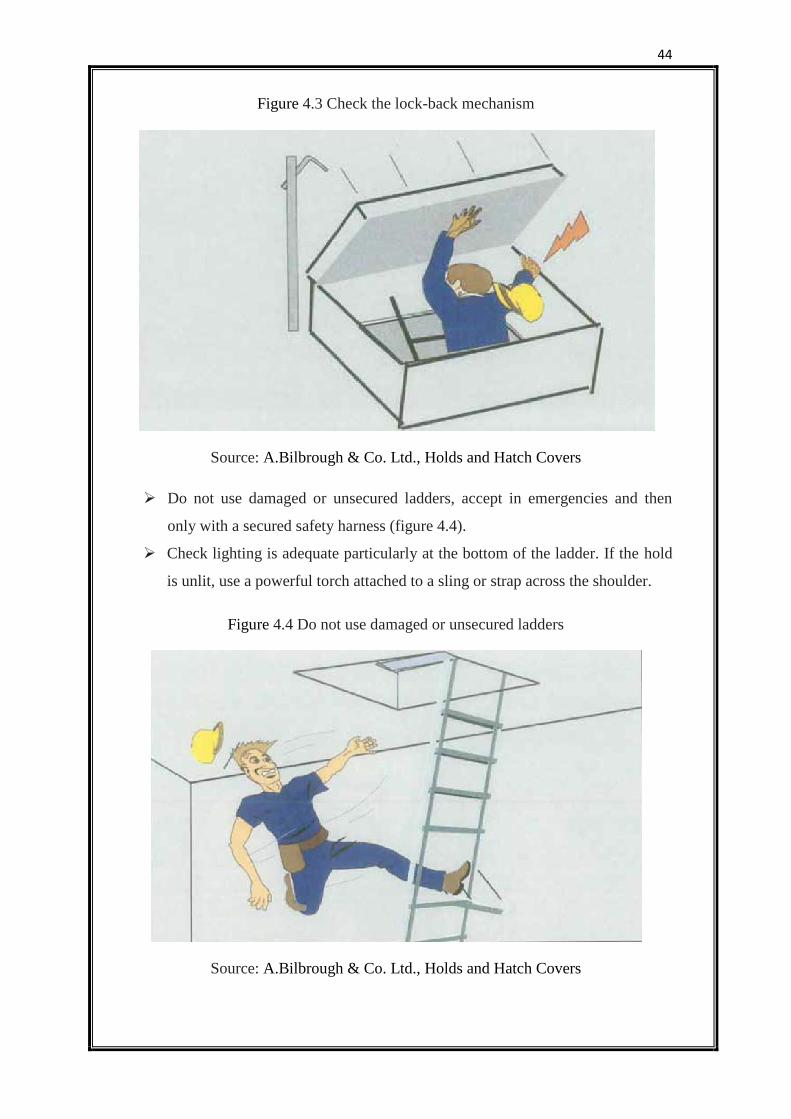
44
Figure 4.3 Check the lock-back mechanism
Source: A.Bilbrough & Co. Ltd., Holds and Hatch Covers
Do not use damaged or unsecured ladders, accept in emergencies and then
only with a secured safety harness (figure 4.4).
Check lighting is adequate particularly at the bottom of the ladder. If the hold
is unlit, use a powerful torch attached to a sling or strap across the shoulder.
Figure 4.4 Do not use damaged or unsecured ladders
Source: A.Bilbrough & Co. Ltd., Holds and Hatch Covers
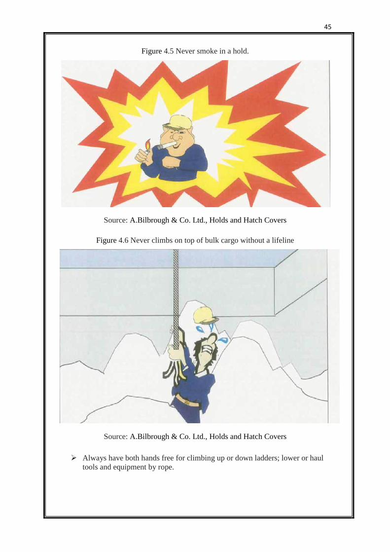
45
Figure 4.5 Never smoke in a hold.
Source: A.Bilbrough & Co. Ltd., Holds and Hatch Covers
Figure 4.6 Never climbs on top of bulk cargo without a lifeline
Source: A.Bilbrough & Co. Ltd., Holds and Hatch Covers
Always have both hands free for climbing up or down ladders; lower or haul
tools and equipment by rope.
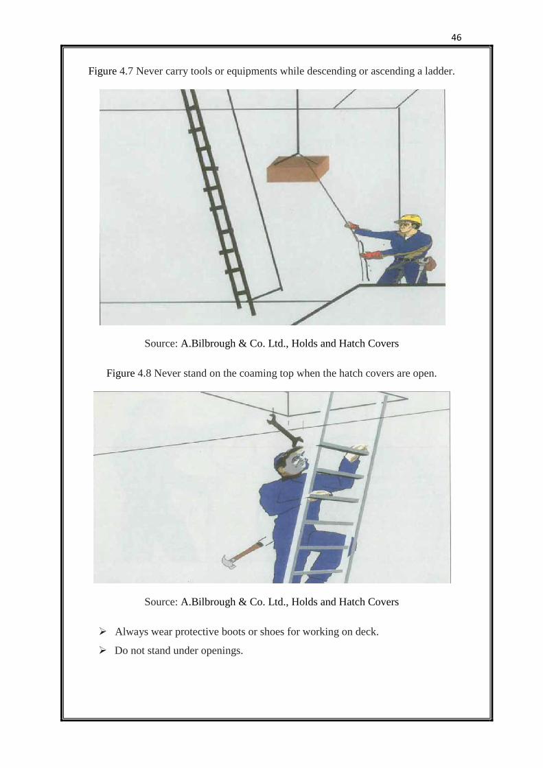
46
Figure 4.7 Never carry tools or equipments while descending or ascending a ladder.
Source: A.Bilbrough & Co. Ltd., Holds and Hatch Covers
Figure 4.8 Never stand on the coaming top when the hatch covers are open.
Source: A.Bilbrough & Co. Ltd., Holds and Hatch Covers
Always wear protective boots or shoes for working on deck.
Do not stand under openings.
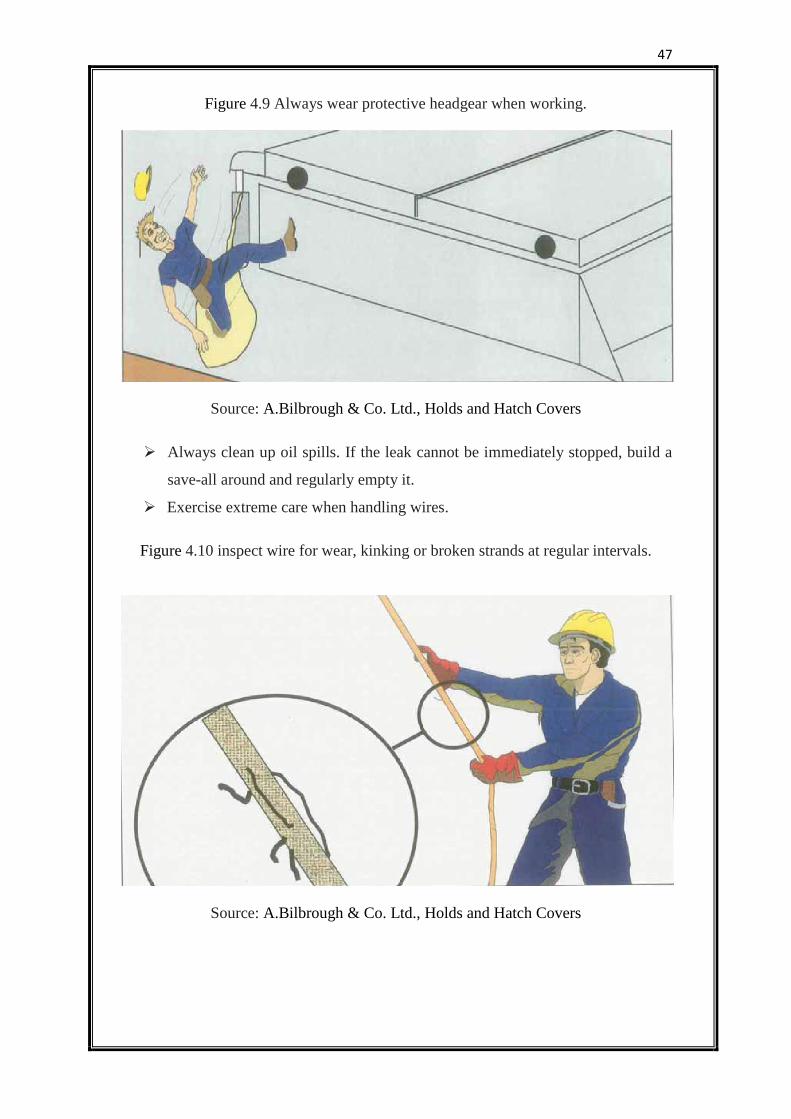
47
Figure 4.9 Always wear protective headgear when working.
Source: A.Bilbrough & Co. Ltd., Holds and Hatch Covers
Always clean up oil spills. If the leak cannot be immediately stopped, build a
save-all around and regularly empty it.
Exercise extreme care when handling wires.
Figure 4.10 inspect wire for wear, kinking or broken strands at regular intervals.
Source: A.Bilbrough & Co. Ltd., Holds and Hatch Covers
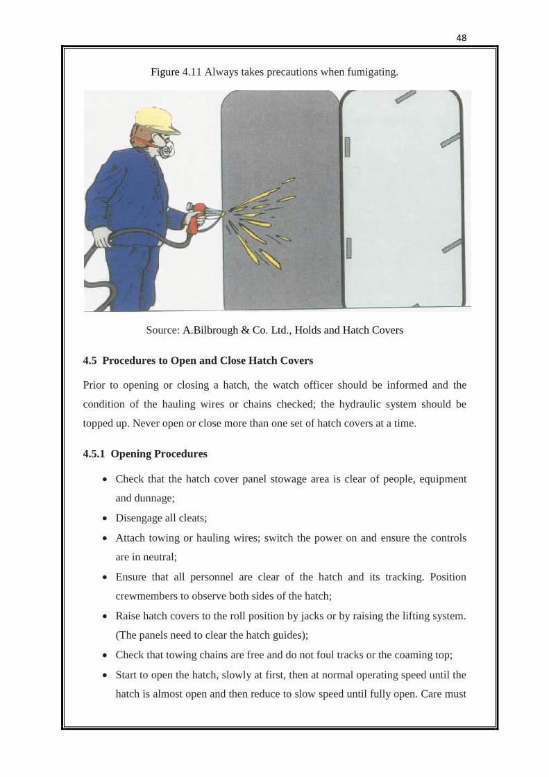
48
Figure 4.11 Always takes precautions when fumigating.
Source: A.Bilbrough & Co. Ltd., Holds and Hatch Covers
4.5 Procedures to Open and Close Hatch Covers
Prior to opening or closing a hatch, the watch officer should be informed and the
condition of the hauling wires or chains checked; the hydraulic system should be
topped up. Never open or close more than one set of hatch covers at a time.
4.5.1 Opening Procedures
Check that the hatch cover panel stowage area is clear of people, equipment
and dunnage;
Disengage all cleats;
Attach towing or hauling wires; switch the power on and ensure the controls
are in neutral;
Ensure that all personnel are clear of the hatch and its tracking. Position
crewmembers to observe both sides of the hatch;
Raise hatch covers to the roll position by jacks or by raising the lifting system.
(The panels need to clear the hatch guides);
Check that towing chains are free and do not foul tracks or the coaming top;
Start to open the hatch, slowly at first, then at normal operating speed until the
hatch is almost open and then reduce to slow speed until fully open. Care must
49
be taken when opening hatch covers especially when the speed of opening can
be only partially controlled;
When fully open, secure the hatch with the safety hook or pin before the
power is switched off.
If applicable, remove the towing and hauling wires;
Install portable safety rails, if supplied.
4.5.2 Closing Procedures
Check that the coaming top is clear of cargo or debris;
Check and clear drain channels and entrances to the drain valves;
Check that any damaged wheel tracks, compression bars and landing pads
have been repaired;
Ensure that the hold is clear of people and that access hatches or entrance
doors are open. Check towing chains are free;
Attach towing or hauling wires, switch the power on and ensure the controls
are in neutral;
Remove portable handrails;
Release hatch locking pins or hooks;
Avoid injuries by ensuring that all personnel are clear of the hatch. Position
crewmembers to observe both sides of the hatch;
Check that towing chains are free and do not foul tracks or the coaming top;
Start to close the hatches slowly at first with the speed of closure being
gradually increased to the normal operating speed. As the hatch reaches the
closed position the speed should be gradually reduced. Great care must be
taken when closing hatch covers;
Lower hatch covers into guide pockets using jacks or lifting cylinders. Some
hatches are lowered automatically;
Attach cleats before removing the towing wire or switching power off;
Finally, check no one is in the hold before closing hold access hatches or other
hold entry points.
50
4.6 Maintenance and Repair
Poor maintenance of hatch covers causes leakage leading to cargo damage and
represents a hazard to the ship and its crew. Although hatch covers are simple and
durable, their sealing gaskets are easily damaged. The quality of sealing is affected by
lack of alignment and poor gasket compression. When hatch covers are opened at the
end of an ocean voyage, look for signs of leakage such as rust staining or drip marks.
Regular adjustment and repair, by ship’s staff, will reduce the overall cost of
maintenance. Painting double drainage channels will help to prevent corrosion.
Always keep a detailed record of maintenance. Take care during extensive
hatch cover repair to avoid cover distortion.
4.6.1 Rubber Gaskets
Keep clean and free from paint. If physically damaged, permanently set-in or aged,
replace with minimum 1 metre lengths. Always follow the manufacturer’s instructions
when renewing gaskets.
4.6.2 Gasket Channels
If gasket channels are badly corroded, causing the hatch packing to hang loose, the
packing should be removed and the channel repaired by welding new metal strips
which should be painted before fitting new rubber. Always follow proper fire
prevention safety procedures. Make sure that cargo spaces are free of cargo and
combustible material. When conducting extensive structural repairs, remove the hatch
covers to shore.
4.6.3 Hatch Cover Structure
Repair or replace any damaged, worn or defective hatch covers or coamings. Consult
with the ship’s classification society before commencing repair. Paint new structure
immediately.
4.6.4 Compression Bars
Effective sealing is only possible with a straight, undamaged and non-corroded
compression bar. Compression bars which are not in this condition should be repaired
or replaced, taking care to align the bars properly.
51
Remember to carry out a chalk test to check alignment, both during and after repair.
4.6.5 Landing Pads
Hatch sealing is arranged by design to give the correct compression of the gasket
when there is metal-to-metal contact on the hatch landing pad, side plate, or inter-
panel block. If landing pads are reduced in height (check with manufacturers’
drawings) because of wear, repair is essential.
4.6.6 Hatch Wheel Track Ways
Track ways can corrode. They are weakened by abrasive wear and tear. When
weakened, track ways can distort and break, affecting hatch movement and alignment.
Deterioration is visible to the naked eye. Repair by replacing the worn or damaged
material with sufficient new material to restore strength. Always keep hatch wheel
track ways clean and painted.
4.6.7 Hatch Coamings
Look for cracks at coaming corners. If any are found, consult the ship’s classification
society before commencing repairs in case the coaming needs to be reinforced.
Examine coaming support brackets for corrosion where they connect with the
ship’s deck. Make sure coamings and their support brackets are painted.
Coamings can be damaged by cargo equipment during loading or discharge.
Look out for damage and repair if found.
4.6.8 Hatch Cleats and Wedges
It is important for compression washers to be adjusted correctly. A locking nut for
adjusting compression is situated at the base of the cleat. The procedure to alter
compression (see illustrations) is as follows:
Close hatch and secure for sea;
Place the cam of the cleat in the hatch socket as if to lock it, but leave it
unlocked (the cam should move freely and fit snugly in its housing);
Adjust the locking nut until the compression washer touches the underside of
the hatch coaming or its steel washer;
Turn the locking nut one full turn to achieve the desired tension;
52
Do not over-tighten;
Protect the thread on completion.
When closing and securing a hatch for sea passage, check the tension in side
cleats. Cleats should never be adjusted in isolation, adjust all cleats along the hatch
skirt at the same time.
4.6.9 Hatch Cross-Joints
It is essential for the cross-joint to be in good condition and properly aligned.
Maintenance and repair should focus on:
Examination of the cross-joint structure for corrosion.
Examination of joint hinges for pin wear, blade cracking or weld failure.
(Re-grease the hinge pin bushes making sure grease reaches the hinge pins).
Examination of the steel-to-steel inter-panel blocks and locators for wear.
(Check the top plate of hatch panels, they should be level when closed).
Checking the gap between panels when they are closed. Misalignment could
be caused by an incorrectly adjusted cylinder or the wheel tracks could be
worn.
4.6.10 Hatch Wheels
Hatch wheel spindles and bearings (where fitted) need to be greased regularly. Check
the wheel spindle for wear and the wheel housing for physical damage. Repair if the
spindle is worn or if the wheels are out of alignment.
4.6.11 Drain Channels and Non-Return Valves
Clean coaming tops and cross-joint channels by removing any loose scale or cargo
residue by brushing or hosing. Clean coaming drain holes and check that the non-
return valve is functioning.
4.6.12 Greasing
Wheel spindles, cleat spindles, hinge pins, hydraulic cylinder protective sheaths, cleat
wedges, drive chain sprockets, toothed rack and cylinder spherical bearings need to be
kept well-greased. Re-grease every month if necessary, and always apply new grease
after the ship has passed through heavy weather.
53
4.6.13 Painting
Corrosion occurs mainly at the panel ends along the cross-joint or where access is
difficult, but it can also occur on the underside of a panel, especially along hatch
beams. Regular painting will be necessary.
4.6.14 Inert Gas
Hatch covers with a double skin, in the form of a closed box, are filled with inert gas.
After structural repair, the inner spaces must be re-inerted. This is done by inserting
special tablets (available from the hatch cover manufacturer) into the space and
welding shut. Never allow water to penetrate the box construction.
4.6.15 Hydraulic Systems and Components
The cleanliness and viscosity of hydraulic oil must be checked. Samples of the oil
should be sent to a chemist for testing (use the same company that checks and tests
your fuel and lubricating oil). The hydraulic system is provided with bleed points
from which samples can be taken.
Hydraulic oil should be changed every five years or after there have been
significant repairs, such as piping or cylinder replacement.
Hydraulic oil filters should be changed every twelve months. Do not
contemplate repairing the hydraulic system without the proper components and skilled
fitters.
4.6.16 Use of Sealing Tape and Foam Fillers
The use of sealing tape and foam fillers should be limited to:
Emergency use. When hatches are known or thought to be leaking and there is
insufficient time to complete permanent repairs;
Charterers’ requirement. Charterers may require owners to apply sealing tape
when highly water-sensitive cargoes are carried;
Fumigation tape is usually applied to hatch covers during fumigation. The tape
is not heavy duty and should be removed when fumigation has finished.
Foam fillers can be used to fill the air space which is formed along the cross-
joint of two closed panels. In heavy weather foam fillers may be washed away, their
use should never be solely relied upon to prevent water ingress.
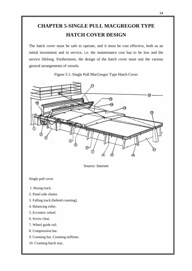
54
CHAPTER 5-SINGLE PULL MACGREGOR TYPE
HATCH COVER DESIGN
The hatch cover must be safe to operate, and it must be cost effective, both as an
initial investment and in service, i.e. the maintenance cost has to be low and the
service lifelong. Furthermore, the design of the hatch cover must suit the various
general arrangements of vessels.
Figure 5.1: Single Pull MacGregor Type Hatch Cover
Source: Internet
Single pull cover
1. Rising track.
2. Panel side chains.
3. Falling track (behind coaming).
4. Balancing roller.
5. Eccentric wheel.
6. Screw cleat.
7. Wheel guide rail.
8. Compression bar.
9. Coaming bar, Coaming stiffener.
10. Coaming hatch stay.
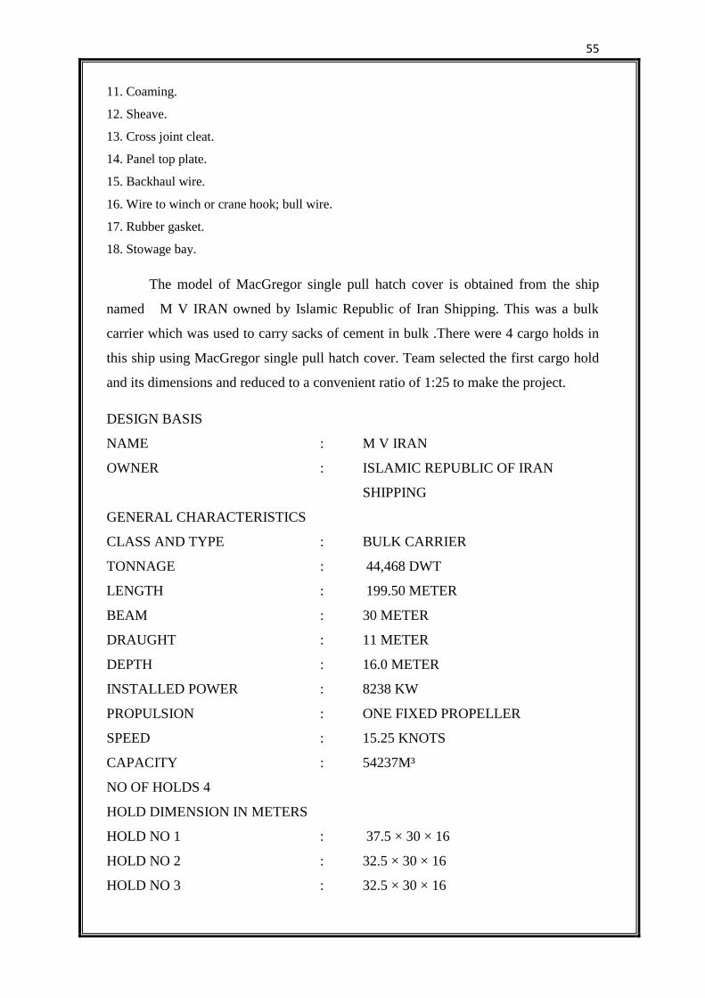
55
11. Coaming.
12. Sheave.
13. Cross joint cleat.
14. Panel top plate.
15. Backhaul wire.
16. Wire to winch or crane hook; bull wire.
17. Rubber gasket.
18. Stowage bay.
The model of MacGregor single pull hatch cover is obtained from the ship
named M V IRAN owned by Islamic Republic of Iran Shipping. This was a bulk
carrier which was used to carry sacks of cement in bulk .There were 4 cargo holds in
this ship using MacGregor single pull hatch cover. Team selected the first cargo hold
and its dimensions and reduced to a convenient ratio of 1:25 to make the project.
DESIGN BASIS
NAME : M V IRAN
OWNER : ISLAMIC REPUBLIC OF IRAN
SHIPPING
GENERAL CHARACTERISTICS
CLASS AND TYPE : BULK CARRIER
TONNAGE : 44,468 DWT
LENGTH : 199.50 METER
BEAM : 30 METER
DRAUGHT : 11 METER
DEPTH : 16.0 METER
INSTALLED POWER : 8238 KW
PROPULSION : ONE FIXED PROPELLER
SPEED : 15.25 KNOTS
CAPACITY : 54237M³
NO OF HOLDS 4
HOLD DIMENSION IN METERS
HOLD NO 1 : 37.5 × 30 × 16
HOLD NO 2 : 32.5 × 30 × 16
HOLD NO 3 : 32.5 × 30 × 16
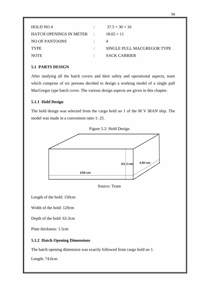
56
HOLD NO 4 : 37.5 × 30 × 16
HATCH OPENINGS IN METER : 18.65 × 11
NO OF PANTOONS : 4
TYPE : SINGLE PULL MACGREGOR TYPE
NOTE : SACK CARRIER
5.1 PARTS DESIGN
After studying all the hatch covers and their safety and operational aspects, team
which comprise of six persons decided to design a working model of a single pull
MacGregor type hatch cover. The various design aspects are given in this chapter.
5.1.1 Hold Design
The hold design was selected from the cargo hold no 1 of the M V IRAN ship. The
model was made in a convenient ratio 1: 25.
Figure 5.2: Hold Design
Source: Team
Length of the hold: 150cm
Width of the hold: 120cm
Depth of the hold: 63.3cm
Plate thickness: 1.5cm
5.1.2 Hatch Opening Dimensions
The hatch opening dimension was exactly followed from cargo hold no 1.
Length: 74.6cm
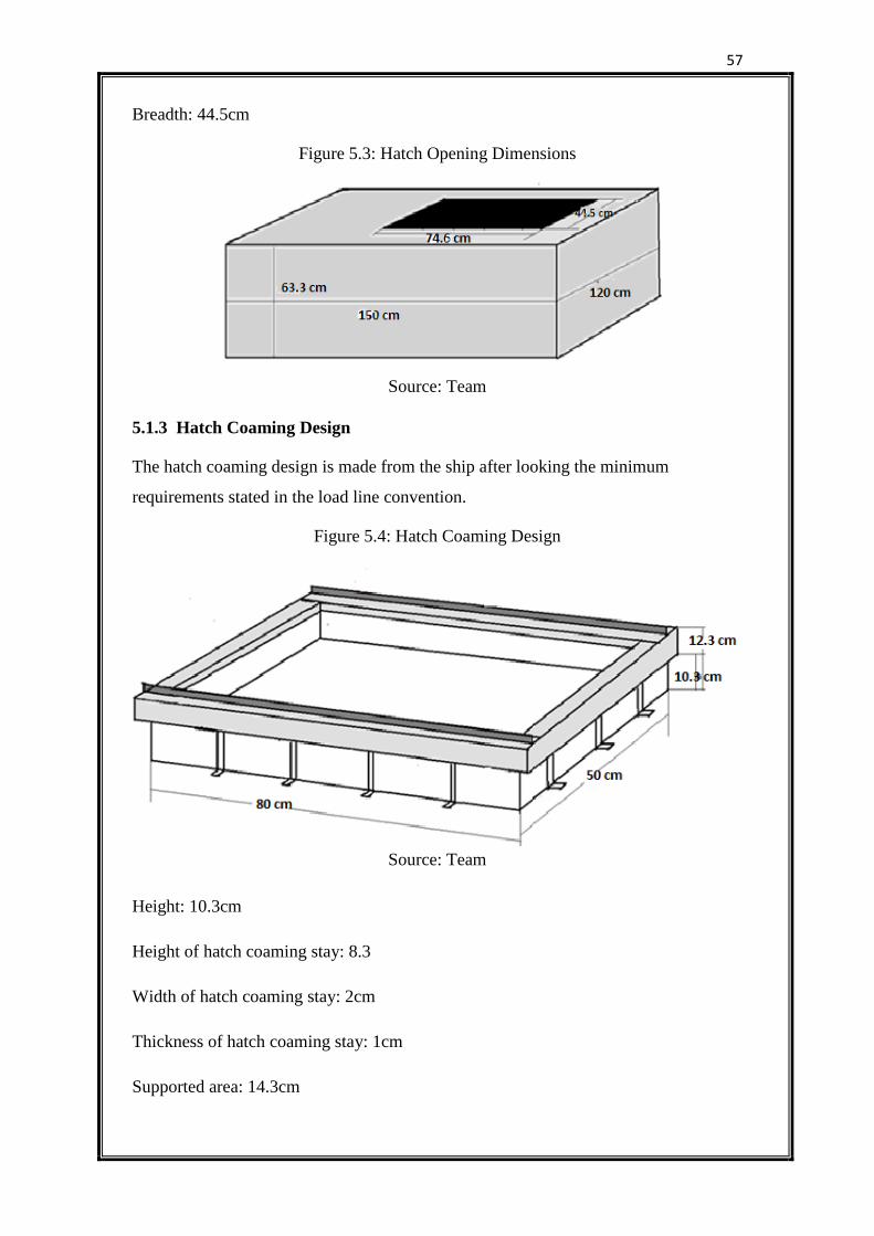
57
Breadth: 44.5cm
Figure 5.3: Hatch Opening Dimensions
Source: Team
5.1.3 Hatch Coaming Design
The hatch coaming design is made from the ship after looking the minimum
requirements stated in the load line convention.
Figure 5.4: Hatch Coaming Design
Source: Team
Height: 10.3cm
Height of hatch coaming stay: 8.3
Width of hatch coaming stay: 2cm
Thickness of hatch coaming stay: 1cm
Supported area: 14.3cm
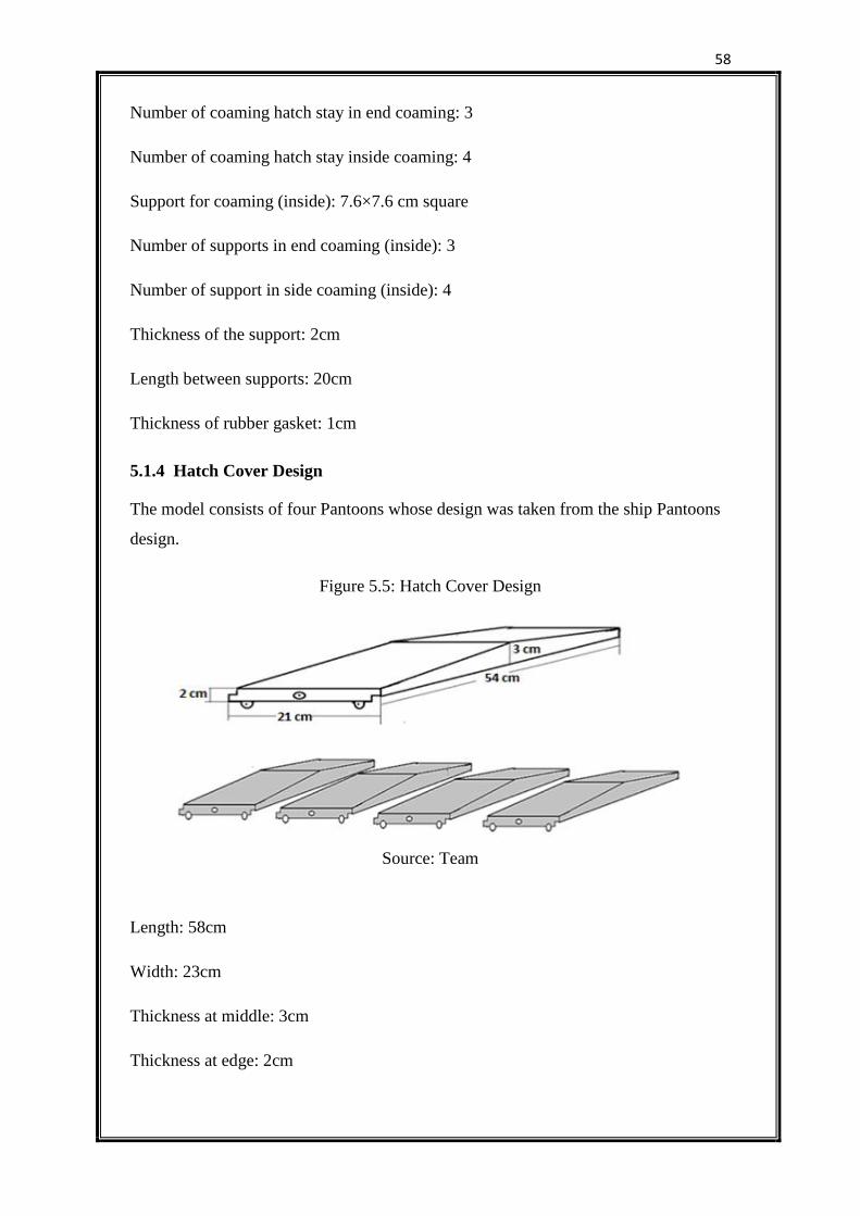
58
Number of coaming hatch stay in end coaming: 3
Number of coaming hatch stay inside coaming: 4
Support for coaming (inside): 7.6×7.6 cm square
Number of supports in end coaming (inside): 3
Number of support in side coaming (inside): 4
Thickness of the support: 2cm
Length between supports: 20cm
Thickness of rubber gasket: 1cm
5.1.4 Hatch Cover Design
The model consists of four Pantoons whose design was taken from the ship Pantoons
design.
Figure 5.5: Hatch Cover Design
Source: Team
Length: 58cm
Width: 23cm
Thickness at middle: 3cm
Thickness at edge: 2cm
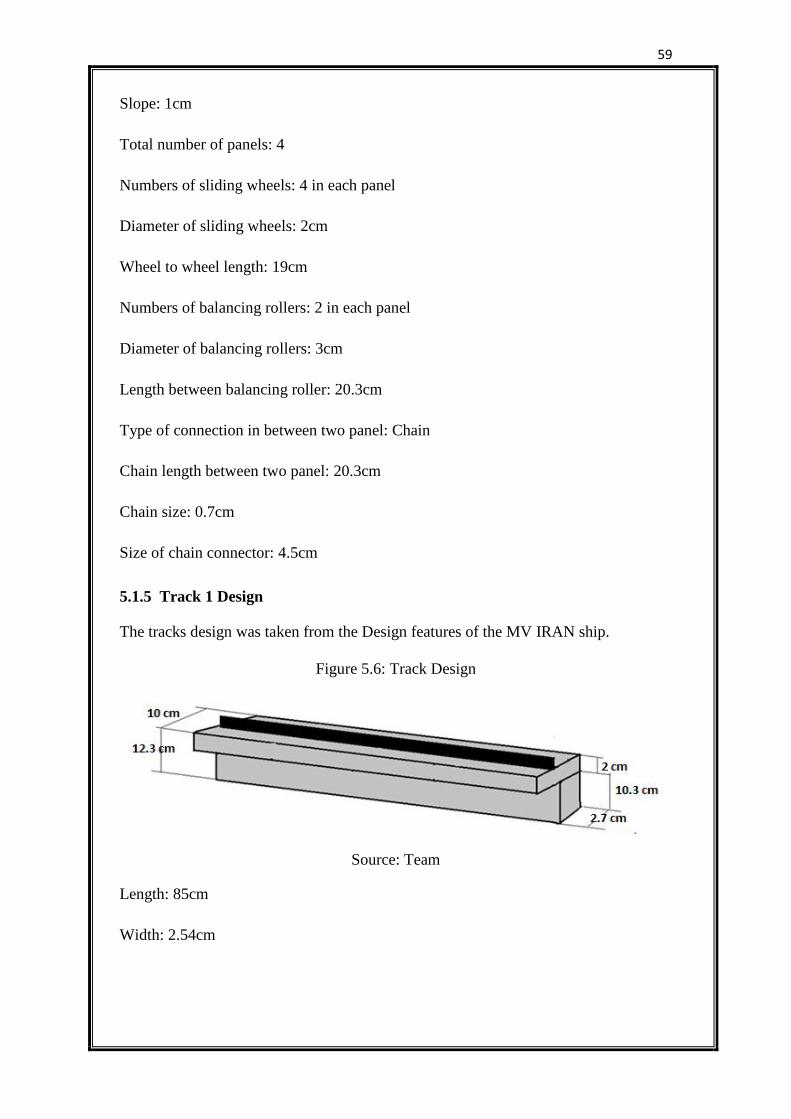
59
Slope: 1cm
Total number of panels: 4
Numbers of sliding wheels: 4 in each panel
Diameter of sliding wheels: 2cm
Wheel to wheel length: 19cm
Numbers of balancing rollers: 2 in each panel
Diameter of balancing rollers: 3cm
Length between balancing roller: 20.3cm
Type of connection in between two panel: Chain
Chain length between two panel: 20.3cm
Chain size: 0.7cm
Size of chain connector: 4.5cm
5.1.5 Track 1 Design
The tracks design was taken from the Design features of the MV IRAN ship.
Figure 5.6: Track Design
Source: Team
Length: 85cm
Width: 2.54cm
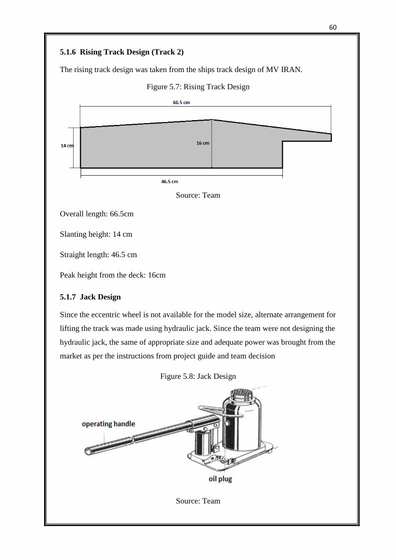
60
5.1.6 Rising Track Design (Track 2)
The rising track design was taken from the ships track design of MV IRAN.
Figure 5.7: Rising Track Design
Source: Team
Overall length: 66.5cm
Slanting height: 14 cm
Straight length: 46.5 cm
Peak height from the deck: 16cm
5.1.7 Jack Design
Since the eccentric wheel is not available for the model size, alternate arrangement for
lifting the track was made using hydraulic jack. Since the team were not designing the
hydraulic jack, the same of appropriate size and adequate power was brought from the
market as per the instructions from project guide and team decision
Figure 5.8: Jack Design
Source: Team
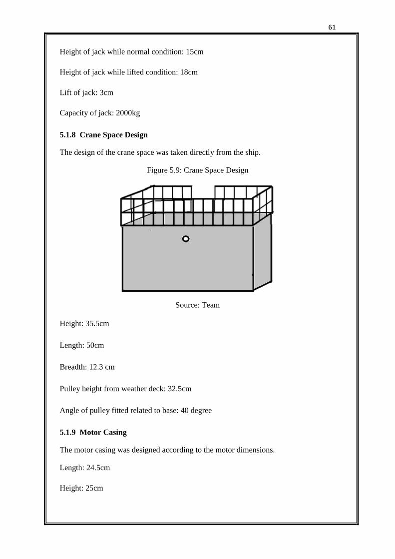
61
Height of jack while normal condition: 15cm
Height of jack while lifted condition: 18cm
Lift of jack: 3cm
Capacity of jack: 2000kg
5.1.8 Crane Space Design
The design of the crane space was taken directly from the ship.
Figure 5.9: Crane Space Design
Source: Team
Height: 35.5cm
Length: 50cm
Breadth: 12.3 cm
Pulley height from weather deck: 32.5cm
Angle of pulley fitted related to base: 40 degree
5.1.9 Motor Casing
The motor casing was designed according to the motor dimensions.
Length: 24.5cm
Height: 25cm
62
Breadth: 10.7cm
5.1.10 Motor Specifications
The motor was selected according to the power required to roll the pantoons over the
track and to pull the pantoons back to position. The motor selection was made after
several trials.
Voltage: 240 V
Current: 12mA
Phase: single phase
Frequency: 50 Hz
Power: 0.003 HP
Torque: 3.5cm
Capacitor: .82 K
Shaft diameter: 1cm
Forward reverse switch: 240 V; 5 Ampere
Push button: 240 V; 5 Ampere
5.1.11 Pulley Design
The pulley was selected according to the dimension of wire rope and the power
required for opening and closing the hatch cover.
Pulley fitted to the motor:
Diameter: 8cm
Numbers: 2
Width: 3cm
63
Pulley for rope
Diameter: 2cm
Width: 1cm
Numbers: 2
5.1.12 Rope
The rope was selected according to the safe working load of the model.
Length: 300cm
Diameter: 3mm
5.1.13 Reduction Gear Design
The selected motor was 60 rpm speed and for the correct working of the hatch cover,
the team designed the reduction gear to reduce the speed into 13 rpm.
Number of teeth in bigger gear: 66
Number of teeth in smaller gear: 13
Actual speed: 60 rpm
Reduced speed:
×60=11.81(12rpm)
5.1.14 Ladder Design
The ladder design was taken from the MV IRAN Ship.
Height: 36cm
Width: 4.7cm
Numbers of steps: 11
Gap between steps: 3.5cm
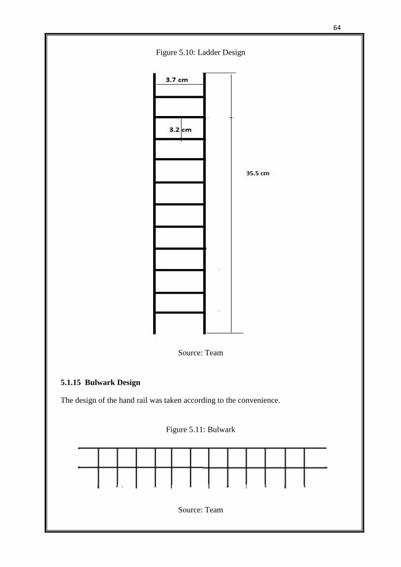
64
Figure 5.10: Ladder Design
Source: Team
5.1.15 Bulwark Design
The design of the hand rail was taken according to the convenience.
Figure 5.11: Bulwark
Source: Team
65
Height from the deck: 7.2cm
Height to the first cross bar: 3.2cm
Gap between bars: 4cm
Cross bar diameter: 0.4cm
5.2 MATERIAL SELECTION
The material was selected according to the availability in the market and for the easy
fabrication process. The material was also chosen by considering economic limits.
After all discussions with the team members and project guide, for the successful
fabrication of the model the team decided to choose the following materials:
Cargo hold : Ply Wood
Hatch Coaming : Wood
Hatch Stay : Wood
Pantoons : Wood
Sliding Wheels : Plastic
Balancing Wheels : Mild Steel
Chain : Metallic
Chain Connector : Galvanised Sheet
Track : Aluminium
Rising Track : Mild steel
Rope : Iron
Track Support : Cast Iron
Motor Casing : Ply Wood
Pulley : 2 Plastics, 2 Copper
Supports : Steels & Aluminium
66
Hand rail : Galvanised Iron
Ladder : Galvanised iron
Hold supports : Ply woods
Side dog : Wooden
Gaskets : Rubber
Gear : Harden steel
Motor shaft : Polished steel
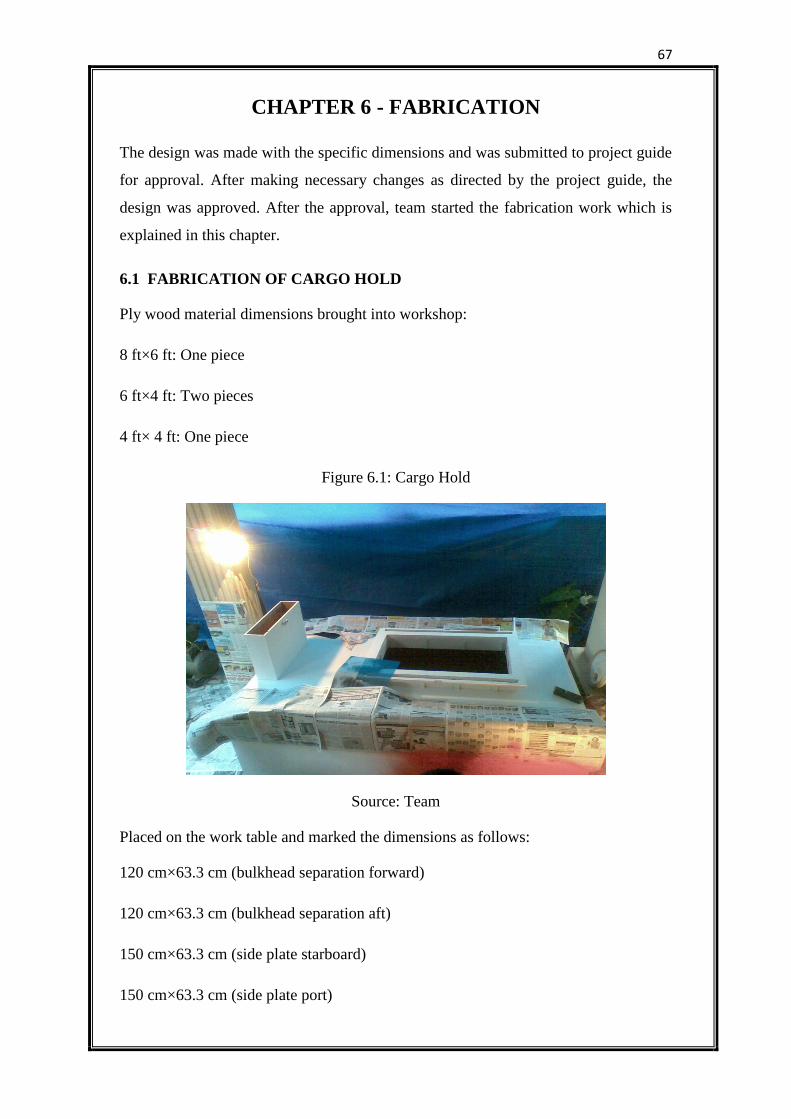
67
CHAPTER 6 - FABRICATION
The design was made with the specific dimensions and was submitted to project guide
for approval. After making necessary changes as directed by the project guide, the
design was approved. After the approval, team started the fabrication work which is
explained in this chapter.
6.1 FABRICATION OF CARGO HOLD
Ply wood material dimensions brought into workshop:
8 ft×6 ft: One piece
6 ft×4 ft: Two pieces
4 ft× 4 ft: One piece
Figure 6.1: Cargo Hold
Source: Team
Placed on the work table and marked the dimensions as follows:
120 cm×63.3 cm (bulkhead separation forward)
120 cm×63.3 cm (bulkhead separation aft)
150 cm×63.3 cm (side plate starboard)
150 cm×63.3 cm (side plate port)
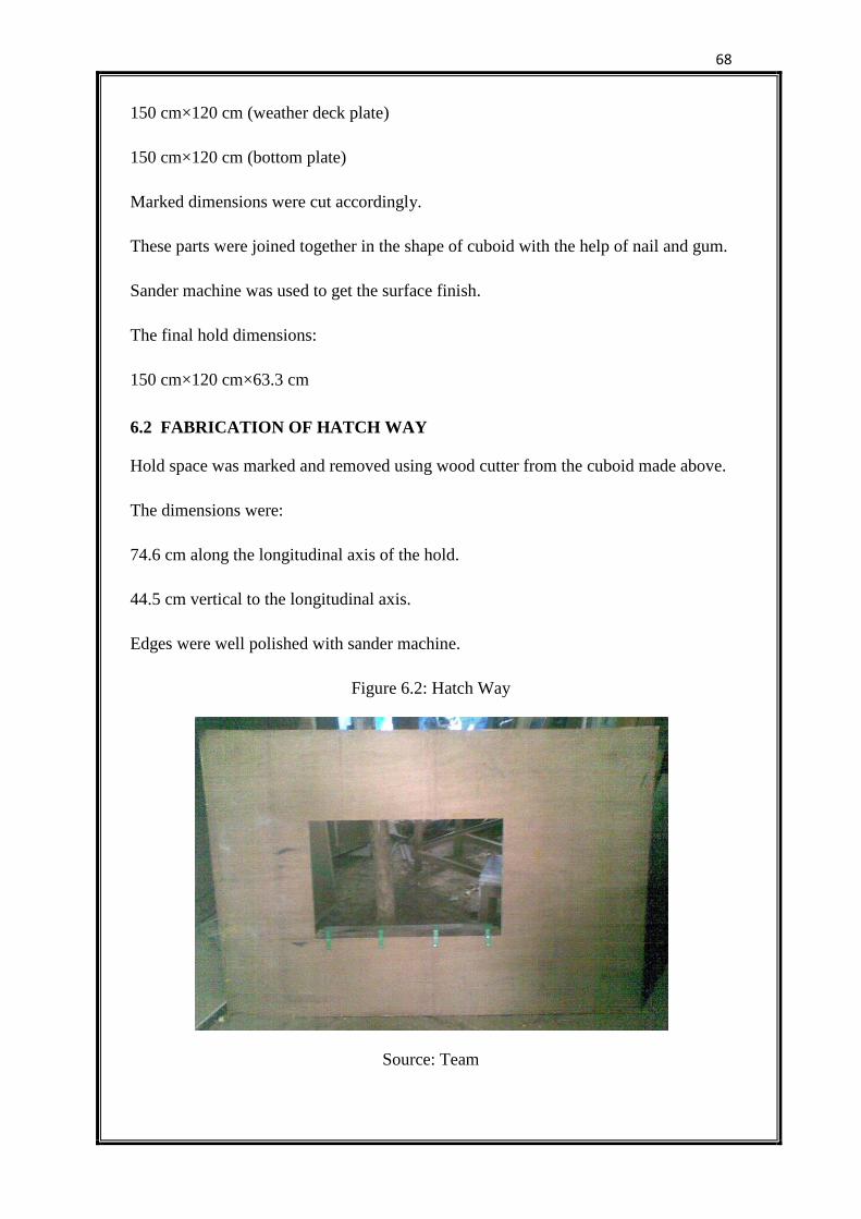
68
150 cm×120 cm (weather deck plate)
150 cm×120 cm (bottom plate)
Marked dimensions were cut accordingly.
These parts were joined together in the shape of cuboid with the help of nail and gum.
Sander machine was used to get the surface finish.
The final hold dimensions:
150 cm×120 cm×63.3 cm
6.2 FABRICATION OF HATCH WAY
Hold space was marked and removed using wood cutter from the cuboid made above.
The dimensions were:
74.6 cm along the longitudinal axis of the hold.
44.5 cm vertical to the longitudinal axis.
Edges were well polished with sander machine.
Figure 6.2: Hatch Way
Source: Team
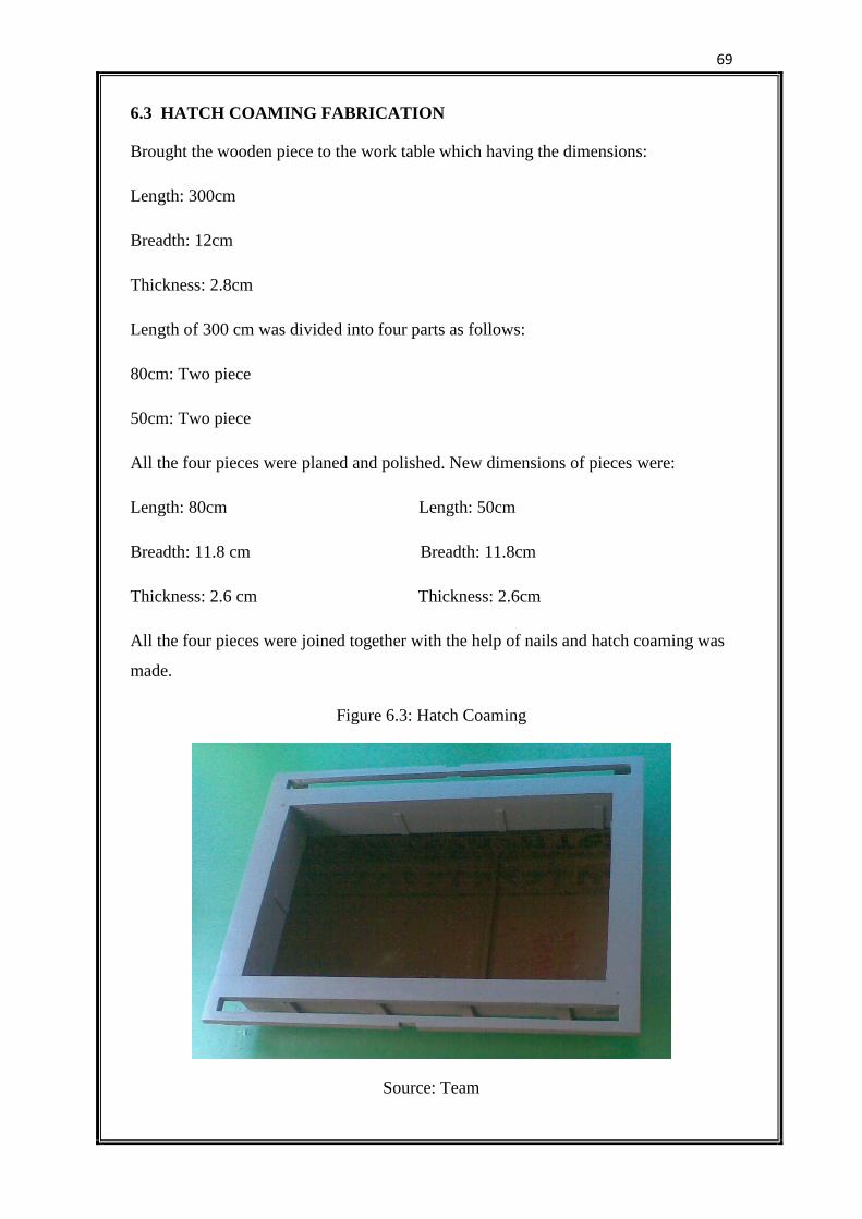
69
6.3 HATCH COAMING FABRICATION
Brought the wooden piece to the work table which having the dimensions:
Length: 300cm
Breadth: 12cm
Thickness: 2.8cm
Length of 300 cm was divided into four parts as follows:
80cm: Two piece
50cm: Two piece
All the four pieces were planed and polished. New dimensions of pieces were:
Length: 80cm Length: 50cm
Breadth: 11.8 cm Breadth: 11.8cm
Thickness: 2.6 cm Thickness: 2.6cm
All the four pieces were joined together with the help of nails and hatch coaming was
made.
Figure 6.3: Hatch Coaming
Source: Team
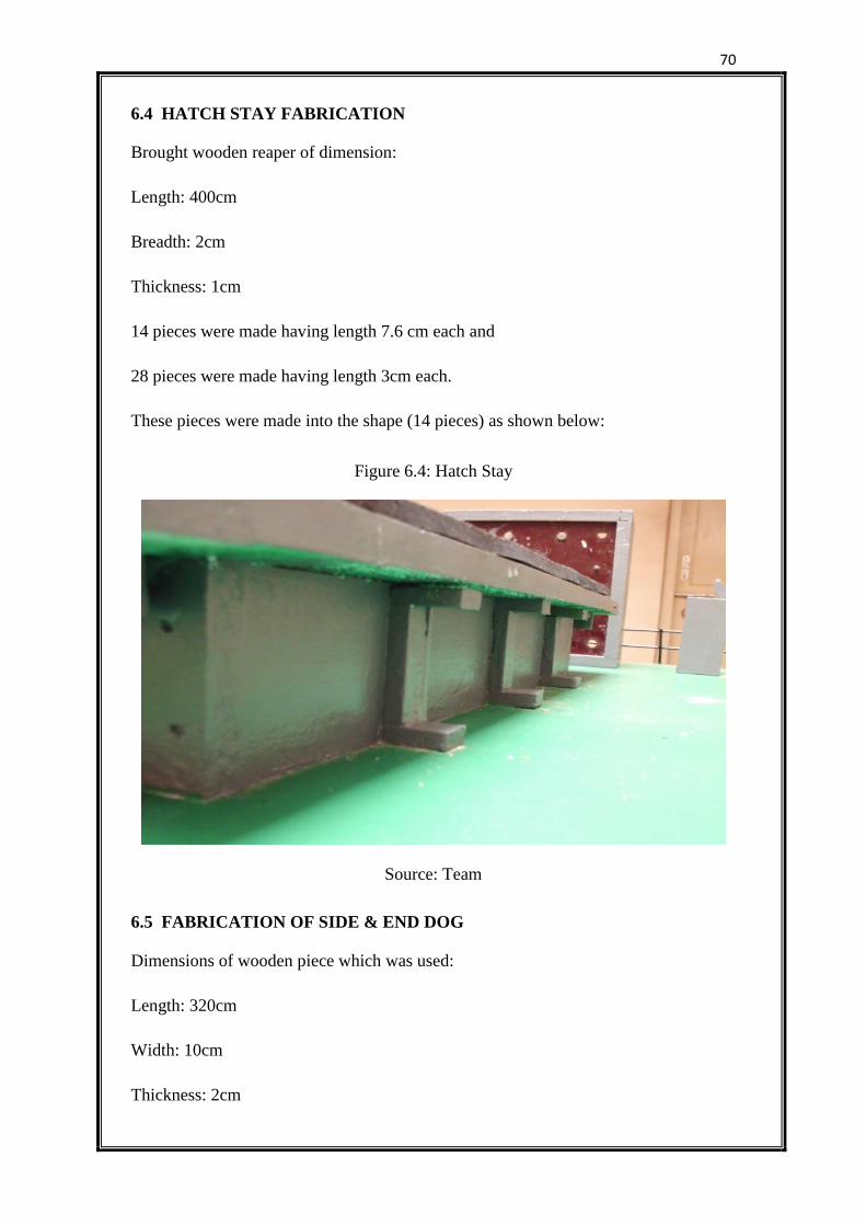
70
6.4 HATCH STAY FABRICATION
Brought wooden reaper of dimension:
Length: 400cm
Breadth: 2cm
Thickness: 1cm
14 pieces were made having length 7.6 cm each and
28 pieces were made having length 3cm each.
These pieces were made into the shape (14 pieces) as shown below:
Figure 6.4: Hatch Stay
Source: Team
6.5 FABRICATION OF SIDE & END DOG
Dimensions of wooden piece which was used:
Length: 320cm
Width: 10cm
Thickness: 2cm
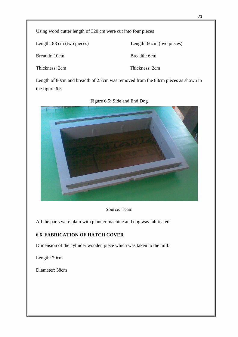
71
Using wood cutter length of 320 cm were cut into four pieces
Length: 88 cm (two pieces) Length: 66cm (two pieces)
Breadth: 10cm Breadth: 6cm
Thickness: 2cm Thickness: 2cm
Length of 80cm and breadth of 2.7cm was removed from the 88cm pieces as shown in
the figure 6.5.
Figure 6.5: Side and End Dog
Source: Team
All the parts were plain with planner machine and dog was fabricated.
6.6 FABRICATION OF HATCH COVER
Dimension of the cylinder wooden piece which was taken to the mill:
Length: 70cm
Diameter: 38cm
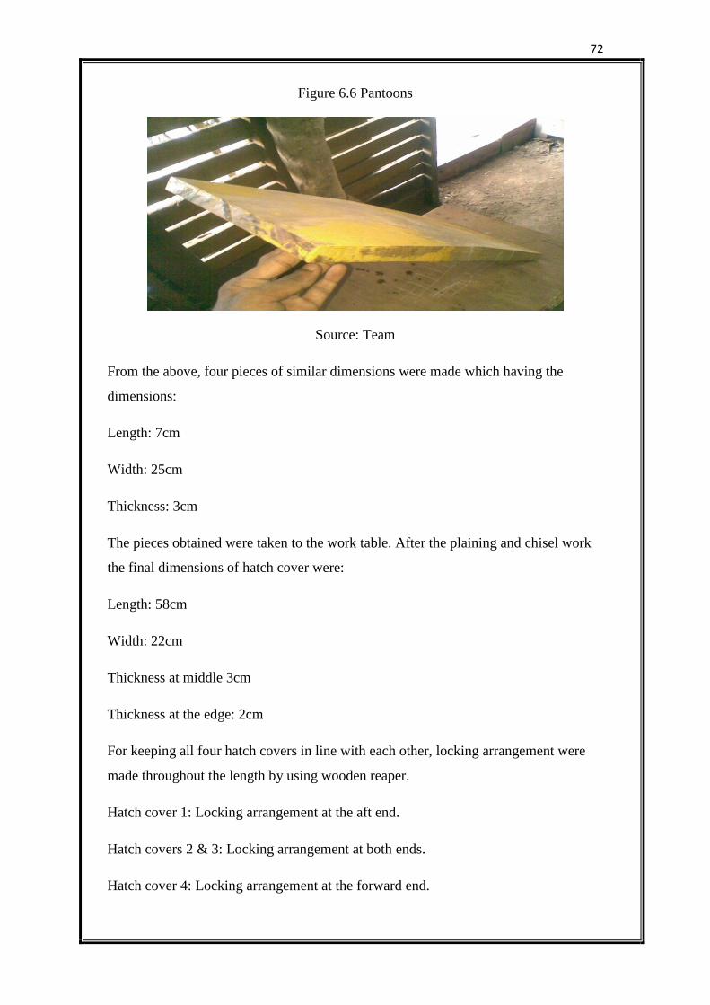
72
Figure 6.6 Pantoons
Source: Team
From the above, four pieces of similar dimensions were made which having the
dimensions:
Length: 7cm
Width: 25cm
Thickness: 3cm
The pieces obtained were taken to the work table. After the plaining and chisel work
the final dimensions of hatch cover were:
Length: 58cm
Width: 22cm
Thickness at middle 3cm
Thickness at the edge: 2cm
For keeping all four hatch covers in line with each other, locking arrangement were
made throughout the length by using wooden reaper.
Hatch cover 1: Locking arrangement at the aft end.
Hatch covers 2 & 3: Locking arrangement at both ends.
Hatch cover 4: Locking arrangement at the forward end.
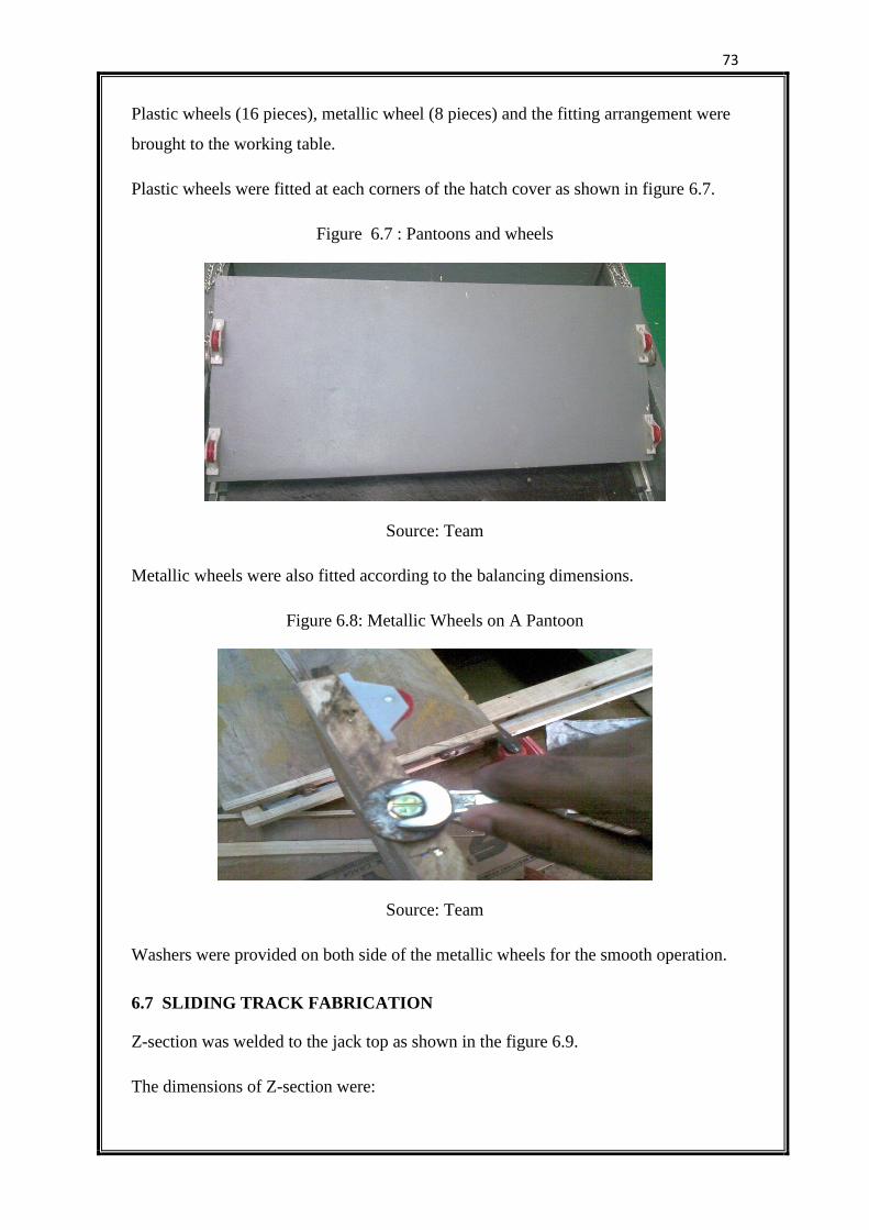
73
Plastic wheels (16 pieces), metallic wheel (8 pieces) and the fitting arrangement were
brought to the working table.
Plastic wheels were fitted at each corners of the hatch cover as shown in figure 6.7.
Figure 6.7 : Pantoons and wheels
Source: Team
Metallic wheels were also fitted according to the balancing dimensions.
Figure 6.8: Metallic Wheels on A Pantoon
Source: Team
Washers were provided on both side of the metallic wheels for the smooth operation.
6.7 SLIDING TRACK FABRICATION
Z-section was welded to the jack top as shown in the figure 6.9.
The dimensions of Z-section were:
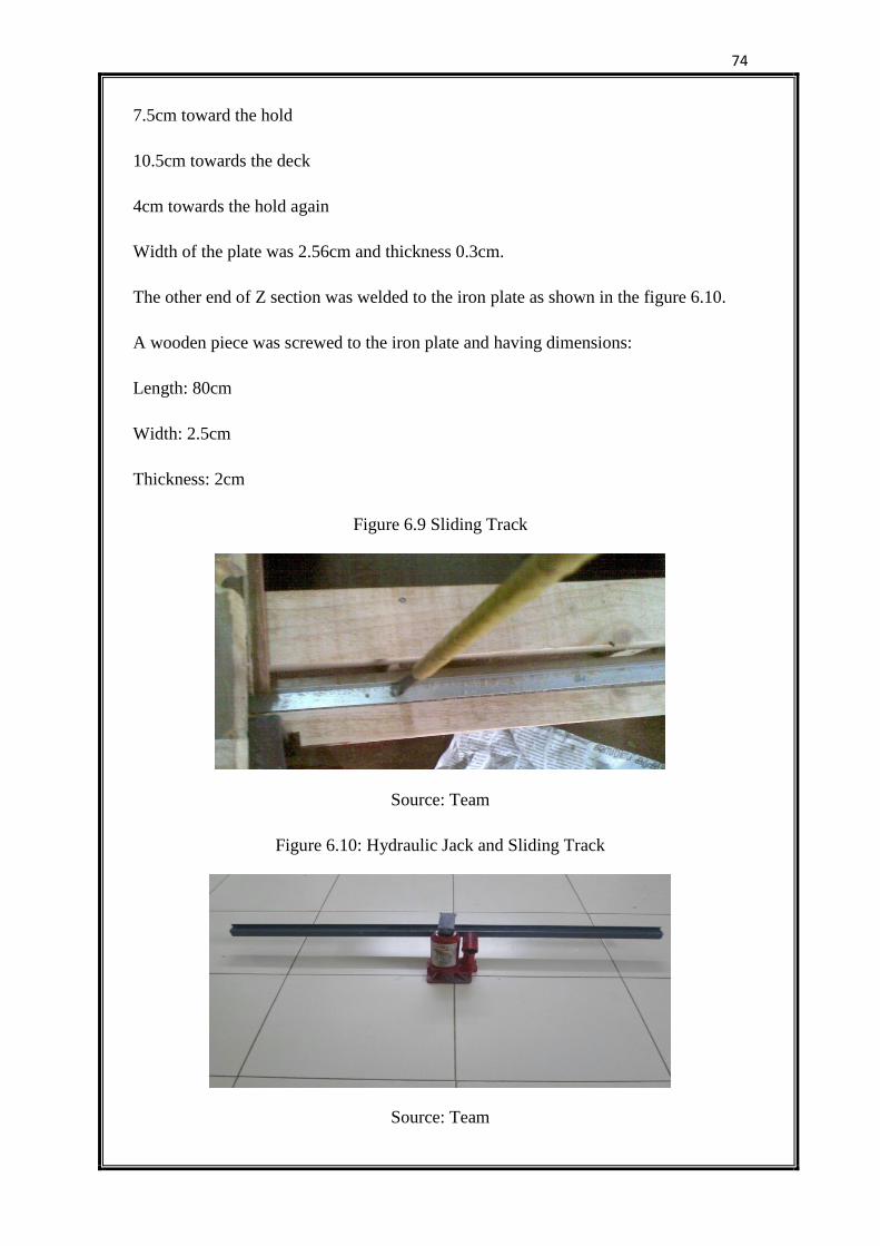
74
7.5cm toward the hold
10.5cm towards the deck
4cm towards the hold again
Width of the plate was 2.56cm and thickness 0.3cm.
The other end of Z section was welded to the iron plate as shown in the figure 6.10.
A wooden piece was screwed to the iron plate and having dimensions:
Length: 80cm
Width: 2.5cm
Thickness: 2cm
Figure 6.9 Sliding Track
Source: Team
Figure 6.10: Hydraulic Jack and Sliding Track
Source: Team
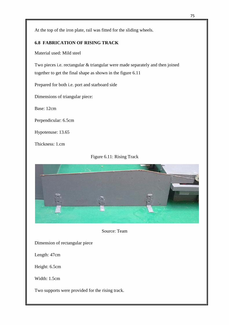
75
At the top of the iron plate, rail was fitted for the sliding wheels.
6.8 FABRICATION OF RISING TRACK
Material used: Mild steel
Two pieces i.e. rectangular & triangular were made separately and then joined
together to get the final shape as shown in the figure 6.11
Prepared for both i.e. port and starboard side
Dimensions of triangular piece:
Base: 12cm
Perpendicular: 6.5cm
Hypotenuse: 13.65
Thickness: 1.cm
Figure 6.11: Rising Track
Source: Team
Dimension of rectangular piece
Length: 47cm
Height: 6.5cm
Width: 1.5cm
Two supports were provided for the rising track.
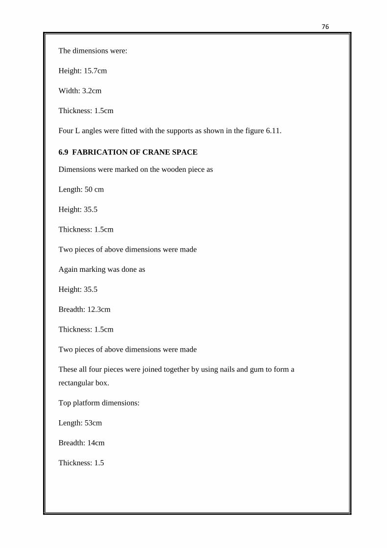
76
The dimensions were:
Height: 15.7cm
Width: 3.2cm
Thickness: 1.5cm
Four L angles were fitted with the supports as shown in the figure 6.11.
6.9 FABRICATION OF CRANE SPACE
Dimensions were marked on the wooden piece as
Length: 50 cm
Height: 35.5
Thickness: 1.5cm
Two pieces of above dimensions were made
Again marking was done as
Height: 35.5
Breadth: 12.3cm
Thickness: 1.5cm
Two pieces of above dimensions were made
These all four pieces were joined together by using nails and gum to form a
rectangular box.
Top platform dimensions:
Length: 53cm
Breadth: 14cm
Thickness: 1.5
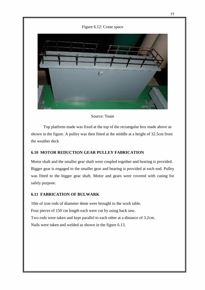
77
Figure 6.12: Crane space
Source: Team
Top platform made was fixed at the top of the rectangular box made above as
shown in the figure. A pulley was then fitted at the middle at a height of 32.5cm from
the weather deck
6.10 MOTOR REDUCTION GEAR PULLEY FABRICATION
Motor shaft and the smaller gear shaft were coupled together and bearing is provided.
Bigger gear is engaged to the smaller gear and bearing is provided at each end. Pulley
was fitted to the bigger gear shaft. Motor and gears were covered with casing for
safely purpose.
6.11 FABRICATION OF BULWARK
10m of iron rods of diameter 4mm were brought to the work table.
Four pieces of 150 cm length each were cut by using hack saw.
Two rods were taken and kept parallel to each other at a distance of 3.2cm.
Nails were taken and welded as shown in the figure 6.13.
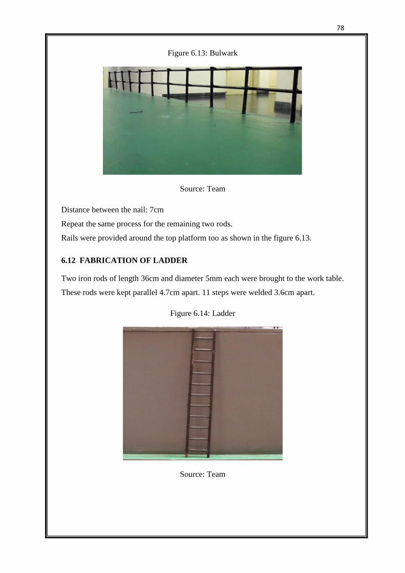
78
Figure 6.13: Bulwark
Source: Team
Distance between the nail: 7cm
Repeat the same process for the remaining two rods.
Rails were provided around the top platform too as shown in the figure 6.13.
6.12 FABRICATION OF LADDER
Two iron rods of length 36cm and diameter 5mm each were brought to the work table.
These rods were kept parallel 4.7cm apart. 11 steps were welded 3.6cm apart.
Figure 6.14: Ladder
Source: Team
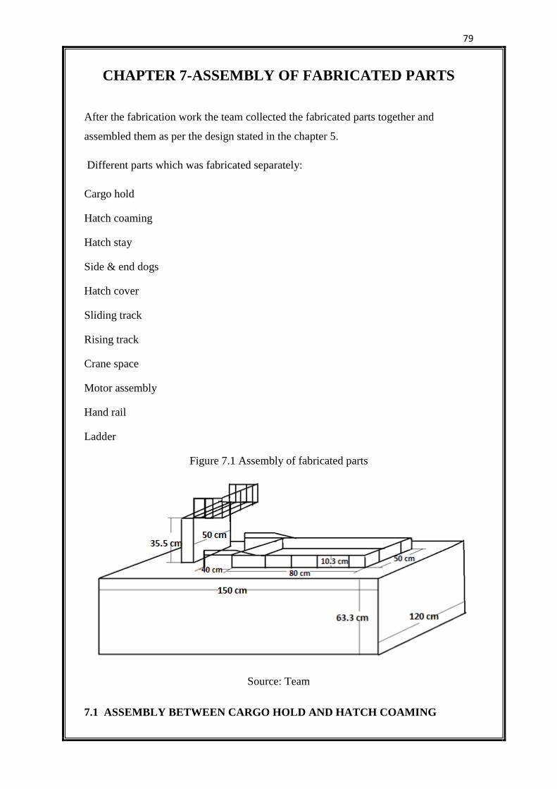
79
CHAPTER 7-ASSEMBLY OF FABRICATED PARTS
After the fabrication work the team collected the fabricated parts together and
assembled them as per the design stated in the chapter 5.
Different parts which was fabricated separately:
Cargo hold
Hatch coaming
Hatch stay
Side & end dogs
Hatch cover
Sliding track
Rising track
Crane space
Motor assembly
Hand rail
Ladder
Figure 7.1 Assembly of fabricated parts
Source: Team
7.1 ASSEMBLY BETWEEN CARGO HOLD AND HATCH COAMING
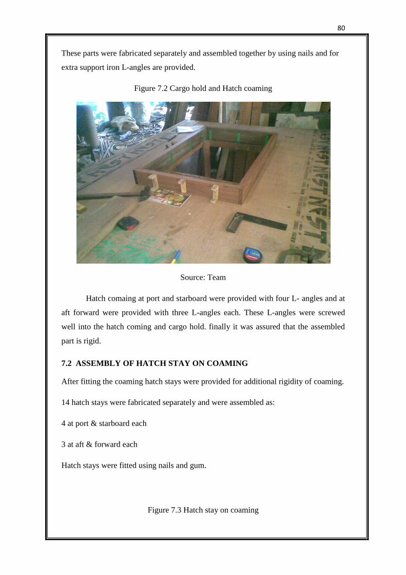
80
These parts were fabricated separately and assembled together by using nails and for
extra support iron L-angles are provided.
Figure 7.2 Cargo hold and Hatch coaming
Source: Team
Hatch comaing at port and starboard were provided with four L- angles and at
aft forward were provided with three L-angles each. These L-angles were screwed
well into the hatch coming and cargo hold. finally it was assured that the assembled
part is rigid.
7.2 ASSEMBLY OF HATCH STAY ON COAMING
After fitting the coaming hatch stays were provided for additional rigidity of coaming.
14 hatch stays were fabricated separately and were assembled as:
4 at port & starboard each
3 at aft & forward each
Hatch stays were fitted using nails and gum.
Figure 7.3 Hatch stay on coaming
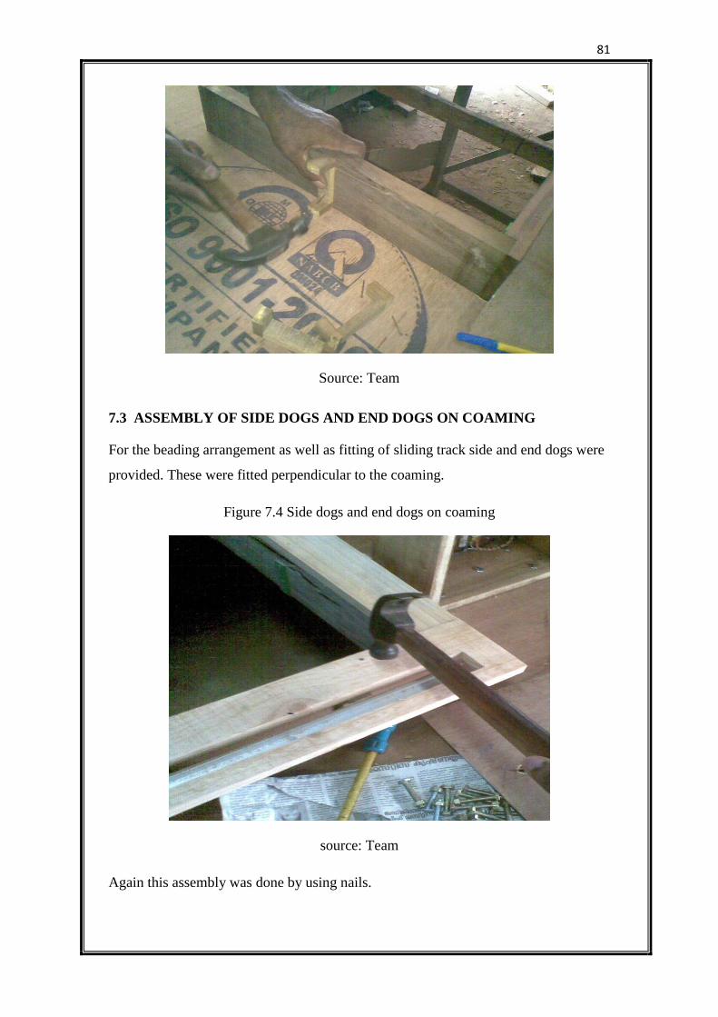
81
Source: Team
7.3 ASSEMBLY OF SIDE DOGS AND END DOGS ON COAMING
For the beading arrangement as well as fitting of sliding track side and end dogs were
provided. These were fitted perpendicular to the coaming.
Figure 7.4 Side dogs and end dogs on coaming
source: Team
Again this assembly was done by using nails.
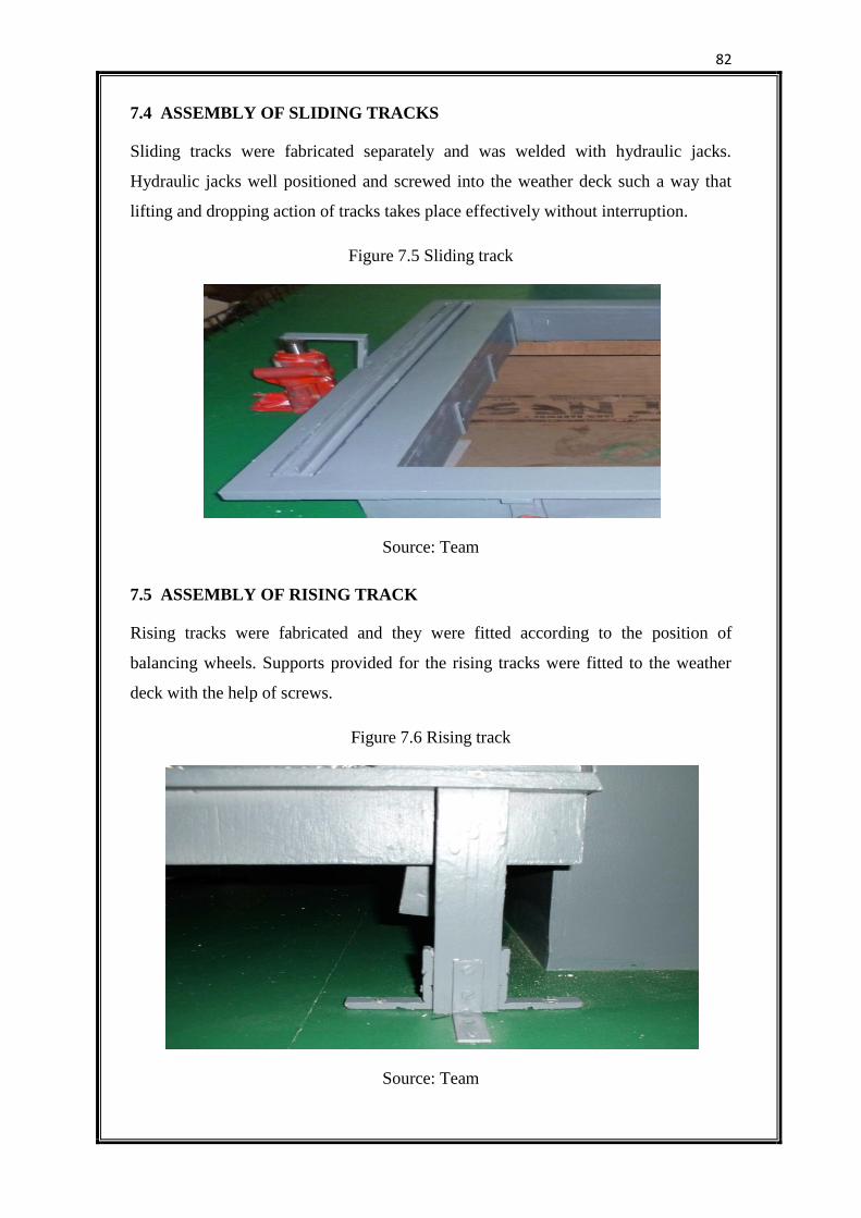
82
7.4 ASSEMBLY OF SLIDING TRACKS
Sliding tracks were fabricated separately and was welded with hydraulic jacks.
Hydraulic jacks well positioned and screwed into the weather deck such a way that
lifting and dropping action of tracks takes place effectively without interruption.
Figure 7.5 Sliding track
Source: Team
7.5 ASSEMBLY OF RISING TRACK
Rising tracks were fabricated and they were fitted according to the position of
balancing wheels. Supports provided for the rising tracks were fitted to the weather
deck with the help of screws.
Figure 7.6 Rising track
Source: Team
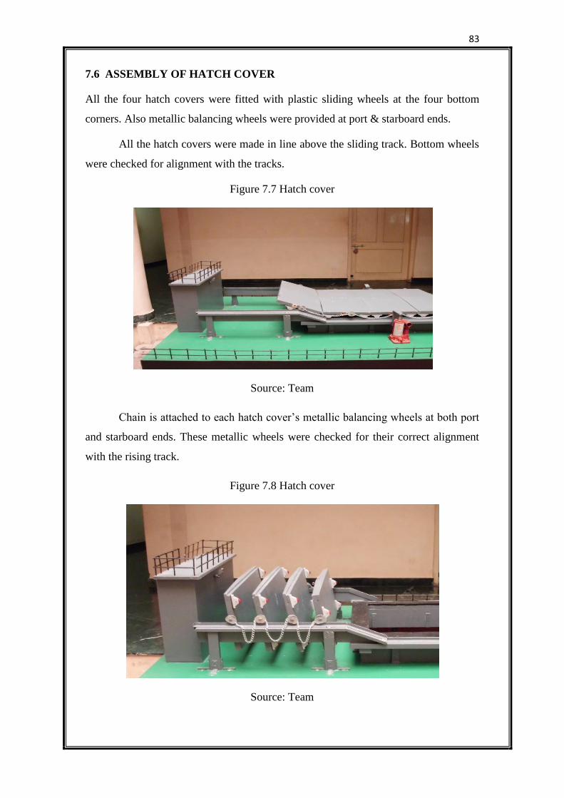
83
7.6 ASSEMBLY OF HATCH COVER
All the four hatch covers were fitted with plastic sliding wheels at the four bottom
corners. Also metallic balancing wheels were provided at port & starboard ends.
All the hatch covers were made in line above the sliding track. Bottom wheels
were checked for alignment with the tracks.
Figure 7.7 Hatch cover
Source: Team
Chain is attached to each hatch cover’s metallic balancing wheels at both port
and starboard ends. These metallic wheels were checked for their correct alignment
with the rising track.
Figure 7.8 Hatch cover
Source: Team
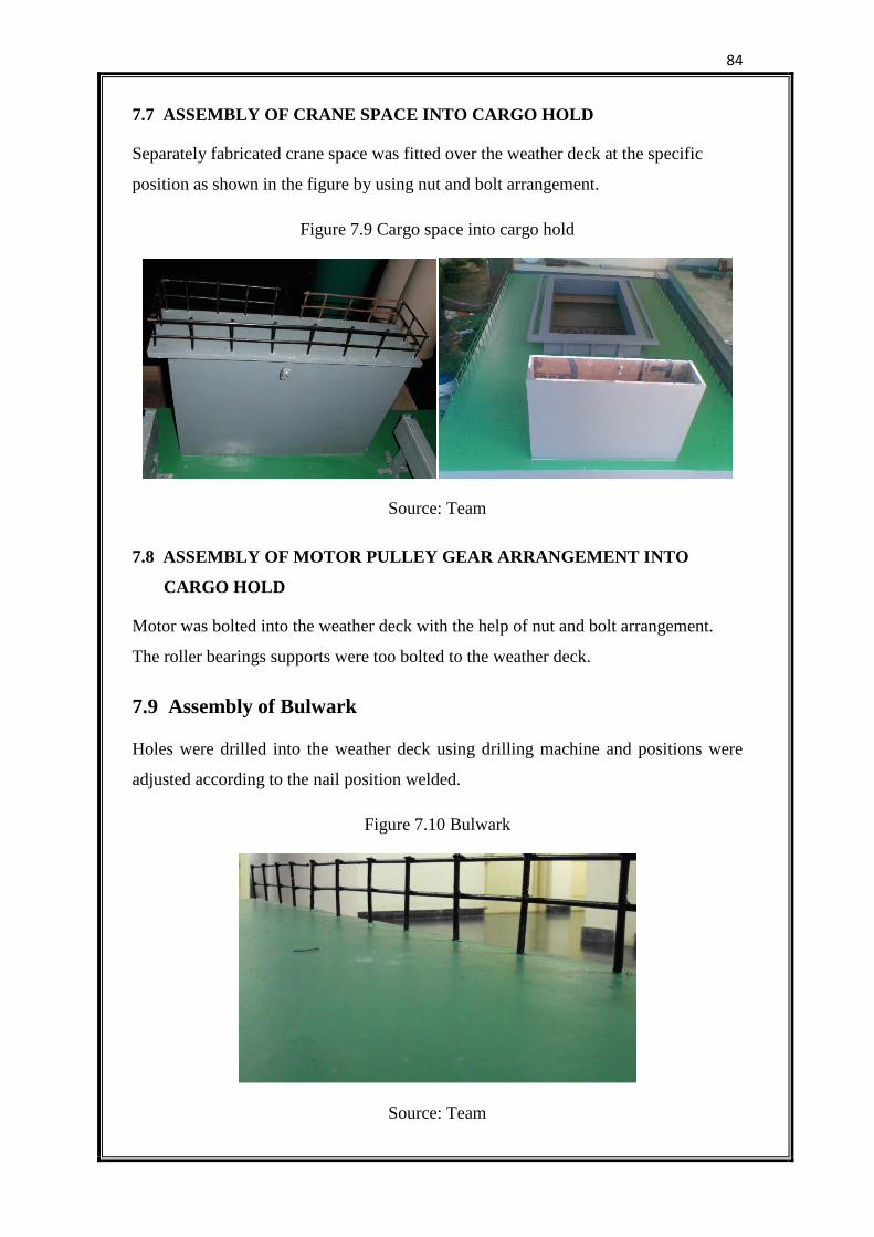
84
7.7 ASSEMBLY OF CRANE SPACE INTO CARGO HOLD
Separately fabricated crane space was fitted over the weather deck at the specific
position as shown in the figure by using nut and bolt arrangement.
Figure 7.9 Cargo space into cargo hold
Source: Team
7.8 ASSEMBLY OF MOTOR PULLEY GEAR ARRANGEMENT INTO
CARGO HOLD
Motor was bolted into the weather deck with the help of nut and bolt arrangement.
The roller bearings supports were too bolted to the weather deck.
7.9 Assembly of Bulwark
Holes were drilled into the weather deck using drilling machine and positions were
adjusted according to the nail position welded.
Figure 7.10 Bulwark
Source: Team
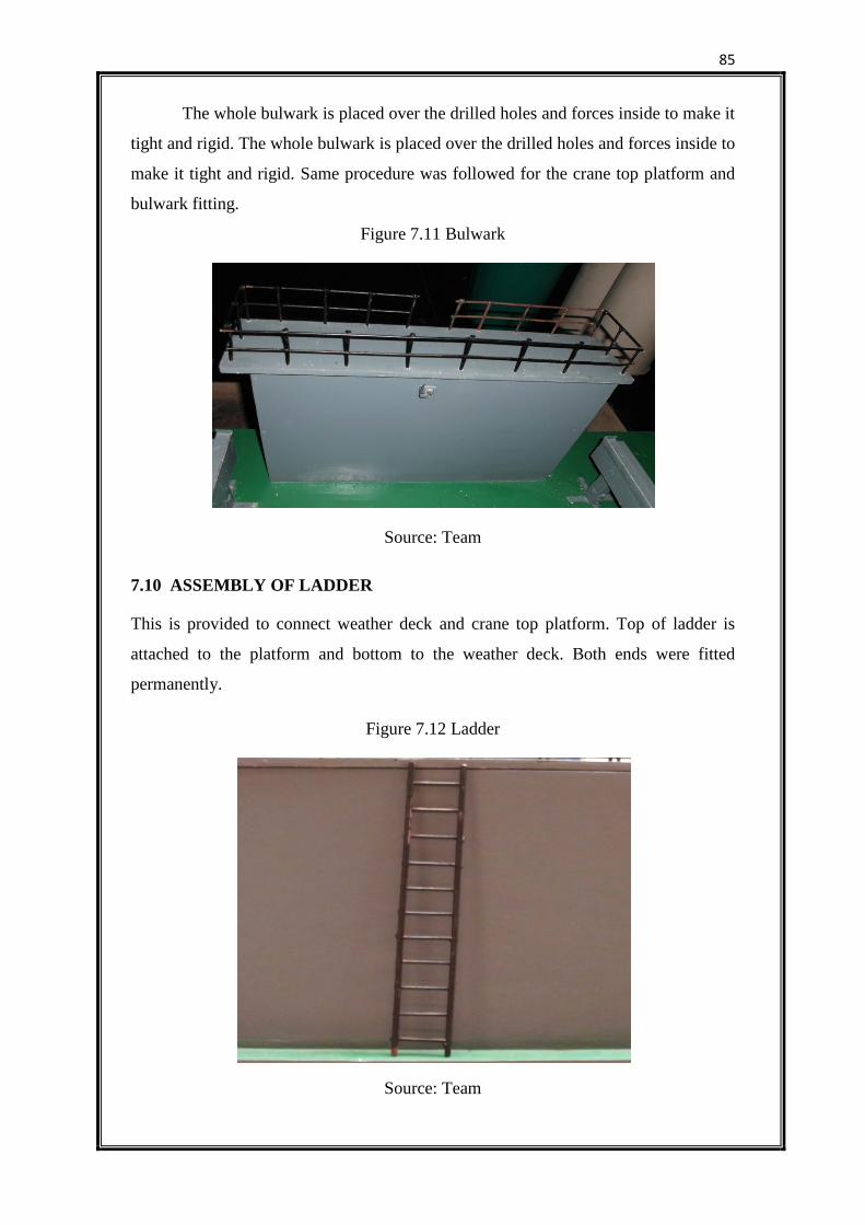
85
The whole bulwark is placed over the drilled holes and forces inside to make it
tight and rigid. The whole bulwark is placed over the drilled holes and forces inside to
make it tight and rigid. Same procedure was followed for the crane top platform and
bulwark fitting.
Figure 7.11 Bulwark
Source: Team
7.10 ASSEMBLY OF LADDER
This is provided to connect weather deck and crane top platform. Top of ladder is
attached to the platform and bottom to the weather deck. Both ends were fitted
permanently.
Figure 7.12 Ladder
Source: Team
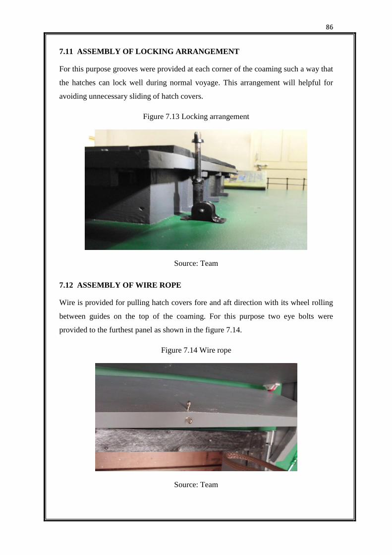
86
7.11 ASSEMBLY OF LOCKING ARRANGEMENT
For this purpose grooves were provided at each corner of the coaming such a way that
the hatches can lock well during normal voyage. This arrangement will helpful for
avoiding unnecessary sliding of hatch covers.
Figure 7.13 Locking arrangement
Source: Team
7.12 ASSEMBLY OF WIRE ROPE
Wire is provided for pulling hatch covers fore and aft direction with its wheel rolling
between guides on the top of the coaming. For this purpose two eye bolts were
provided to the furthest panel as shown in the figure 7.14.
Figure 7.14 Wire rope
Source: Team
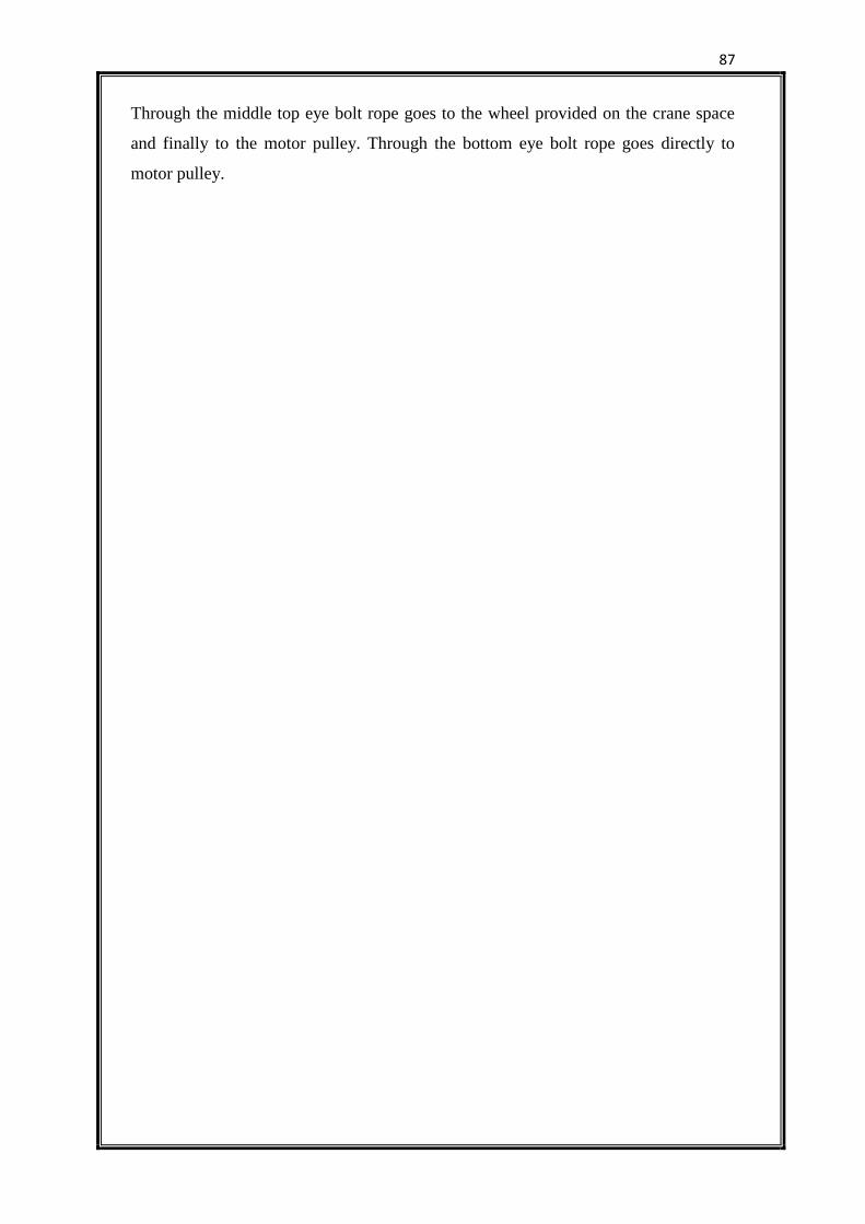
87
Through the middle top eye bolt rope goes to the wheel provided on the crane space
and finally to the motor pulley. Through the bottom eye bolt rope goes directly to
motor pulley.
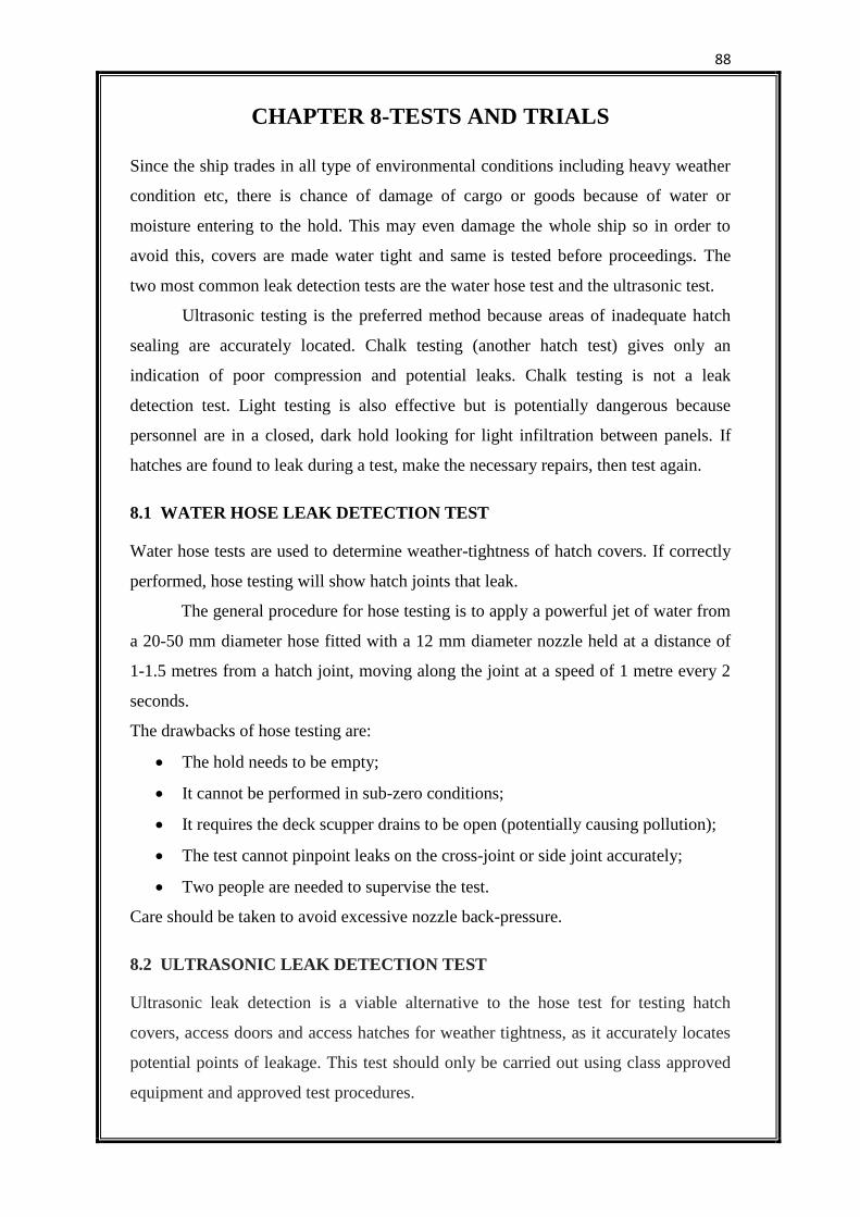
88
CHAPTER 8-TESTS AND TRIALS
Since the ship trades in all type of environmental conditions including heavy weather
condition etc, there is chance of damage of cargo or goods because of water or
moisture entering to the hold. This may even damage the whole ship so in order to
avoid this, covers are made water tight and same is tested before proceedings. The
two most common leak detection tests are the water hose test and the ultrasonic test.
Ultrasonic testing is the preferred method because areas of inadequate hatch
sealing are accurately located. Chalk testing (another hatch test) gives only an
indication of poor compression and potential leaks. Chalk testing is not a leak
detection test. Light testing is also effective but is potentially dangerous because
personnel are in a closed, dark hold looking for light infiltration between panels. If
hatches are found to leak during a test, make the necessary repairs, then test again.
8.1 WATER HOSE LEAK DETECTION TEST
Water hose tests are used to determine weather-tightness of hatch covers. If correctly
performed, hose testing will show hatch joints that leak.
The general procedure for hose testing is to apply a powerful jet of water from
a 20-50 mm diameter hose fitted with a 12 mm diameter nozzle held at a distance of
1-1.5 metres from a hatch joint, moving along the joint at a speed of 1 metre every 2
seconds.
The drawbacks of hose testing are:
The hold needs to be empty;
It cannot be performed in sub-zero conditions;
It requires the deck scupper drains to be open (potentially causing pollution);
The test cannot pinpoint leaks on the cross-joint or side joint accurately;
Two people are needed to supervise the test.
Care should be taken to avoid excessive nozzle back-pressure.
8.2 ULTRASONIC LEAK DETECTION TEST
Ultrasonic leak detection is a viable alternative to the hose test for testing hatch
covers, access doors and access hatches for weather tightness, as it accurately locates
potential points of leakage. This test should only be carried out using class approved
equipment and approved test procedures.
89
The test involves placing (with hatches closed and secure) an electronic signal
generator inside the cargo hold. A sensor is then passed around the outside of all
compression joints. Readings taken by the sensor indicate points of low compression
or potential points of leakage. Ultrasonic testing overcomes the majority of limitations
associated with hose testing and can be carried out when holds are loaded. The
drawbacks of these section tests are:
The equipment requires an experienced and specialist operator to interpret the
readings.
The equipment requires regular calibration;
The equipment is not normally part of the ship’s equipment.
8.3 PUTTY OR MOULDING CLAY TEST
This is a maintenance test mainly used by the maker’s representative to precisely
determine alignment and clearances. Putty or moulding clay is placed at regular
intervals in the packing retaining channels that have no packing in them. The hatch
covers are closed then re-opened leaving an indentation. This allows the exact steet-
to-steel wear down condition to be calculated and any panel distortion or
misalignment to be measured and remedial action taken.
8.4 CHALK TESTING
When performing a chalk test, the top edge of every compression bar is covered with
chalk.
Hatches are then fully closed and reopened. The rubber packing is examined
for a chalk mark, which should run continuously along the packing centre. Gaps in the
chalk mark indicate lack of compression. Chalk testing merely indicates if hatch
panels are aligned and compression achieved. It will not show whether compression is
adequate and therefore it is not a test for weather tightness.
8.5 TOLERANCE TEST FOR HATCH COVERS
This test is conducted on a jig to check the flatness of adjoining panels, as well as the
dimensions and the hinge pin clearances where multiple panels are measured. It also
checks cross joint steel to steel contact wear down.
90
It is a test done following extensive steel repairs to hatch cover panels and is
essential if the panels are of double skinned construction. Always contact the makers
for such testing’s, as original construction information is needed.
8.6 RESULT
Since the model is made of ply wood it cannot withstand the pressure and other
governing regulations, the team was not able to perform the above stated test and
trials. The main idea of presenting the model is to show the working and to know the
basics of the MacGregor type hatch cover.
91
CHAPTER 9 - CONCLUSION
Right from the starting i.e., designing of MacGregor hatch cover to its successful
completion the team has given its full potential for the same. First of all, the suitable
design was made. After taking all precautions and factors into consideration the
fabrication process was performed. As the material selected for the hatch covers was
plywood for the easy fabrication and due to economic limits, the various leak tests
were not performed. The model was completed based on the design taken by the team.
The opening and closing trial of the hatch cover was done many times and it
performed successfully and satisfactorily.
92
REFERENCES
1. A.Bilbrough & Co. Ltd., Holds And Hatch Covers
2. Buxton, I. L., (1978) Cargo Access Equipment for Merchant Ships, London,
ICHCA.
3. Lloyd’s Register, (2002) The Standard 2002, A Master’s Guide To Hatch
Cover Maintenance.
93