single row terminal blocks a3, lp3 & cb3 - electrical … · mp metal inserts with 0.150”...
TRANSCRIPT
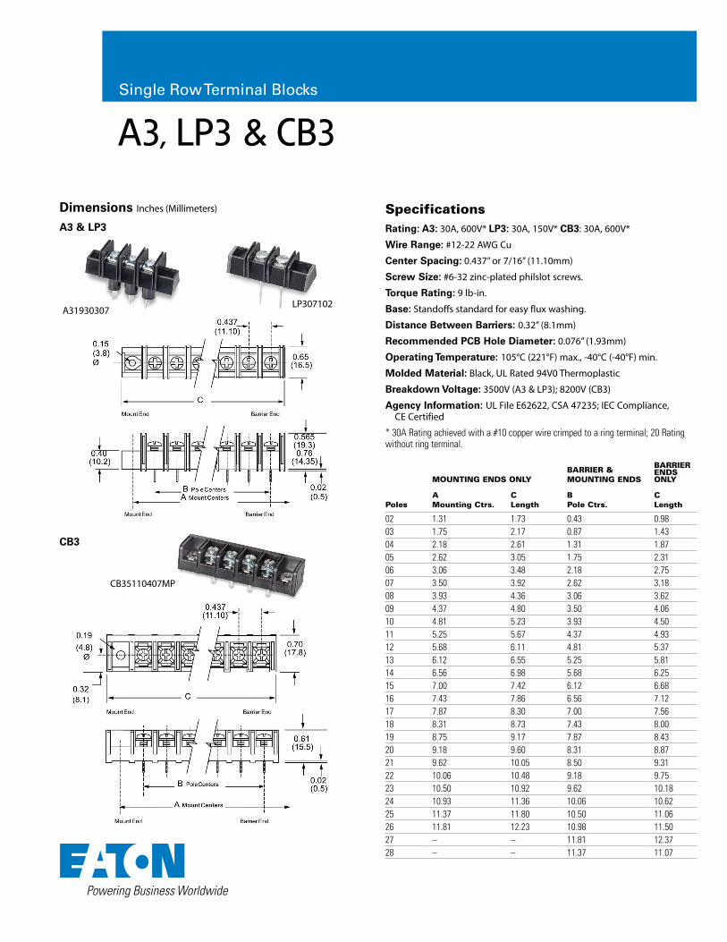
A3, LP3 & CB3
A31930307
Specifications Rating: A3: 30A, 600V* LP3: 30A, 150V* CB3: 30A, 600V*
Wire Range: #12-22 AWG Cu
Center Spacing: 0.437” or 7/16” (11.10mm)
Screw Size: #6-32 zinc-plated philslot screws.
Torque Rating: 9 lb-in.
Base: Standoffs standard for easy flux washing.
Distance Between Barriers: 0.32” (8.1mm)
Recommended PCB Hole Diameter: 0.076” (1.93mm)
Operating Temperature: 105°C (221°F) max., -40°C (-40°F) min.
Molded Material: Black, UL Rated 94V0 Thermoplastic
Breakdown Voltage: 3500V (A3 & LP3); 8200V (CB3)
Agency Information: UL File E62622, CSA 47235; IEC Compliance, CE Certified
* 30A Rating achieved with a #10 copper wire crimped to a ring terminal; 20 Rating without ring terminal.
MOUNTING ENDS ONLYBARRIER & MOUNTING ENDS
BARRIERENDSONLY
PolesAMounting Ctrs.
CLength
BPole Ctrs.
CLength
02 1.31 1.73 0.43 0.9803 1.75 2.17 0.87 1.4304 2.18 2.61 1.31 1.8705 2.62 3.05 1.75 2.3106 3.06 3.48 2.18 2.7507 3.50 3.92 2.62 3.1808 3.93 4.36 3.06 3.6209 4.37 4.80 3.50 4.0610 4.81 5.23 3.93 4.5011 5.25 5.67 4.37 4.9312 5.68 6.11 4.81 5.3713 6.12 6.55 5.25 5.8114 6.56 6.98 5.68 6.2515 7.00 7.42 6.12 6.6816 7.43 7.86 6.56 7.1217 7.87 8.30 7.00 7.5618 8.31 8.73 7.43 8.0019 8.75 9.17 7.87 8.4320 9.18 9.60 8.31 8.8721 9.62 10.05 8.50 9.3122 10.06 10.48 9.18 9.7523 10.50 10.92 9.62 10.1824 10.93 11.36 10.06 10.6225 11.37 11.80 10.50 11.0626 11.81 12.23 10.98 11.5027 – – 11.81 12.3728 – – 11.37 11.07
Dimensions Inches (Millimeters)
A3 & LP3
CB35110407MP
CB3
LP307102
Single Row Terminal Blocks

15
EATON www.eaton.com
Terminal Styles Inches (Millimeters)
Screw Options(Bulk ordering part numbers are in parentheses)
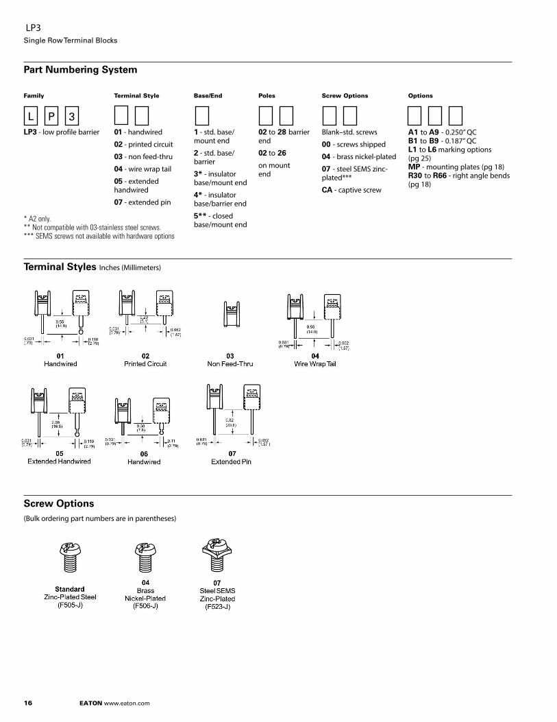
Part Numbering System
Family Terminal Style Base/End Poles Screw Options Options
A3 - standard barrier 01 - handwired
02 - printed circuit
03 - non feed-thru
04 - wire wrap tail
05 - extended handwired
07 - extended pin
09 - 0.250 QC short
10 - 0.187 QC
19 - 0.250 QC long
1 - std. base/mount end
2 - std. base/barrier
3* - insulator base/mount end
4* - insulator base/barrier end
5** - closed base/mount end
02 to 28 barrier end
02 to 26 mount end
Blank–std. screws
03 - stainless steel
04 - brass nickel-plated
07 - steel SEMS zinc-plated***
09 - brass SEMS nickel-plated***
07WR - steel SEMS wire ready
CA† - captive screw
AB - angle mnt. options (pg 18)A1 to A9 - 0.250” QC B1 to B9 - 0.187” QCL1 to L6 marking options (pg 25) MP, MT - mounting plates (pg 18) RC - retaining clips (pg 18)R30 to R66 - right angle bends (pg 18)
* Base/End Styles 3 and 4 not available with 02, 03, and 09 terminals. ** Base/End Note: 5 Style only available with 03 terminals. *** SEMS screws not available with hardware options † Not compatible with 03 stainless steel screw option.
A3Single Row Terminal Blocks
A 3
16
EATON www.eaton.com
Terminal Styles Inches (Millimeters)
Screw Options(Bulk ordering part numbers are in parentheses)
Part Numbering System
Family Terminal Style Base/End Poles Screw Options Options
LP3 - low profile barrier 01 - handwired
02 - printed circuit
03 - non feed-thru
04 - wire wrap tail
05 - extended handwired
07 - extended pin
1 - std. base/mount end
2 - std. base/barrier
3* - insulator base/mount end
4* - insulator base/barrier end
5** - closed base/mount end
02 to 28 barrier end
02 to 26
on mount end
Blank–std. screws
00 - screws shipped
04 - brass nickel-plated
07 - steel SEMS zinc-plated***
CA - captive screw
A1 to A9 - 0.250” QC B1 to B9 - 0.187” QCL1 to L6 marking options (pg 25) MP - mounting plates (pg 18) R30 to R66 - right angle bends (pg 18)
LP3 Single Row Terminal Blocks
L 3P
* A2 only. ** Not compatible with 03-stainless steel screws. *** SEMS screws not available with hardware options

17
EATON www.eaton.com
Hardware Options Inches (Millimeters)
(Bulk ordering part numbers are in parentheses)
Base/End Options Inches (Millimeters)
A3 & LP3Single Row Terminal Blocks
Jumpers Quick Connects Blade Width A = 0.250” Blade Width B = 0.187”
Mount End Details
† Contact Eaton for desired configuration.
Note: On 1, 3 and 5 bases, Eaton may drill a terminal spacing to be a mount end. There will be no fit/form/function effect of mounting the product

18
EATON www.eaton.com
Right Angle Mounting Bracket
Right angle terminals are offered on the A3 & LP3. Configurations are defined in these dimensions: X = pin extension beyond the block base; Z = length from block base to centerline of the terminal tip. Standard bends consist of the X and Z dimensions shown in the chart. Specify by adding the selected Bend Option Code to the terminal part number.
04 Terminal Bend Configurations
Bend Option CodeX (minimum) Z
Available w/insulator base
R36 0.02 0.22 No
R42 0.08 0.16 No
R46 0.12 0.12 No
R50 0.16 0.08 No
Dimensions in inches. To convert to millimeters, multiply by 25.4.
07 Terminal Bend Configurations
Bend Option CodeX (minimum) Z
Available w/insulator base
R36 0.02 0.49 Yes
R50 0.16 0.35 No
R66 0.32 0.19 No
Dimensions in inches. To convert to millimeters, multiply by 25.4.
Angle Brackets (A3 only)
Option AB
Angle brackets enable block to be fastened at right angles to normal mount position. Bulk part number 2AB-J.
Mounting Plates
Options MP & MT
MP Metal inserts with 0.150” dia. hole accept #6 screw.
MT Metal inserts with tapped hole accept #6-32 screw.
Bulk part number 2MP-J, 2MT-J.
Retaining Clip
Options RC
Use on standoff tubes. Fit panels up to 0.125” thick. Two clips for every five positions. Supplied unassembled. Bulk part number H541-J.
A3 & LP3Single Row Terminal Blocks
Mounting Options Inches (Millimeters)

19
EATON www.eaton.com
Terminal Styles Inches (Millimeters)
Screw Options(Bulk ordering part numbers are in parentheses)
CB3 Terminal Exit Options Inches (Millimeters)
Part Numbering System
Family Terminal Style Base/End Poles Screw Options Options
CB3 - closed back 01 - handwired #6-32 screw
02 - printed circuit #6-32 screw
07 - extended pin #6-32 screw
51* - handwired #8-32 screw
52* - printed circuit #8-32 screw
1 - mount end
2 - barrier end
02 to 22 barrior end
02 to 20
on mount end
07 - steel SEMS (standard)
09 - brass SEMS nickel-plated
CA - SEMS captive
A7 to A9 - 0.250” QC B7 to B9 - 0.187” QCEB exit back terminalsL1 to L6 marking options (pg 25) LT1 to LT6 marking options (pg 25) MP mtg. plates (pg 20)Covers - (pg 26)
*Note: #8-32 screw is a special with #6-32 head.
CB3Single Row Terminal Blocks
C 3B

20
EATON www.eaton.com
Hardware OptionsInches (Millimeters)
(Bulk ordering part numbers are in parentheses)
Mounting Options Inches (Millimeters)
Mounting Plates
Options MP
MP Metal inserts with 0.150” dia. hole accept #6 screw.
CB3 Single Row Terminal Blocks
† Contact Eaton for desired configuration.
Eaton Electronics Division1000 Eaton BoulevardCleveland, OH 44122United Stateswww.eaton.com/electronics
© 2017 EatonAll Rights ReservedPrinted in USAPublication No. 10682 — BU-MC17075 December 2017
Eaton is a registered trademark.
All other trademarks are property of their respective owners.
Poles
CB2
CB3
Single Row Terminal Blocks Effective December 2017
Sales and Customer ServiceAmericasEmail: [email protected]
Europe, Middle East, AfricaEmail: [email protected]
ChinaEmail: [email protected]
JapanEmail: [email protected]
KoreaEmail: [email protected]
South East AsiaEmail: [email protected]
TaiwanEmail: [email protected]
Global Technical SupportMagnetics: [email protected] Protection: [email protected]: [email protected]
www.eaton.com/terminalblocks
Eaton’s Electronics Product Selection Tools
PARAMETRIC SEARCHDrill down into the Eaton Electronics product database to find the right part for your application.
IC MATCHINGFind the Eaton Electronics parts called out on IC manufacturers’ demo and evaluation boards.
CROSS REFERENCEFind a cross to a competitor’s product or to an alternate Eaton Electronics part number.
SUPERCAPACITOR CALCULATORDetermine your calculated requirements and design capability.
TERMINAL BLOCK SELECTORFind the right terminal block for any application.
AUTOMOTIVE ELECTRONICS SOLUTIONSFind electronics components for automotive solutions.
tools.eatonelectronics.com
Contact Us Tools