single side auto route pcb design using proteus by mughees
DESCRIPTION
A step by step tutorial guide for single layer auto route pcb in proteusTRANSCRIPT
Made at: BARQILABS www.barqilabs.com
Single Side PCB Design using Proteus Made by : Mughees Sawar Awan1
Engr. Muhammad Fahad Munir Awan2 Email: [email protected] Phone number: +92‐343‐5337123
[email protected] +92‐333‐9747297
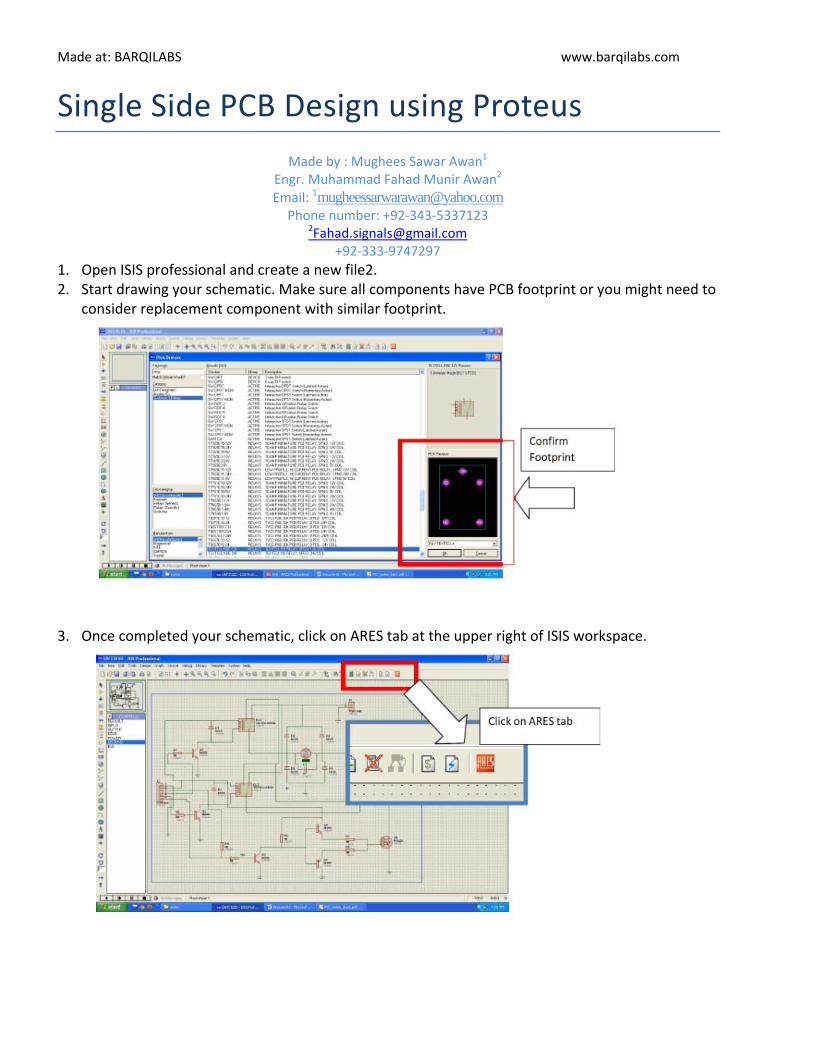
1. Open ISIS professional and create a new file2. 2. Start drawing your schematic. Make sure all components have PCB footprint or you might need to
consider replacement component with similar footprint.
3. Once completed your schematic, click on ARES tab at the upper right of ISIS workspace.
Made at: BARQILABS www.barqilabs.com
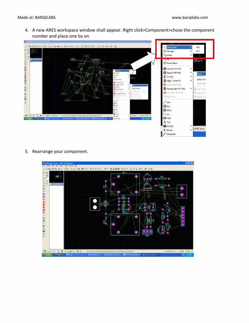
4. A new ARES workspace window shall appear. Right click>Component>chose the component number and place one by on
5. Rearrange your component.

Made at: BARQILABS www.barqilabs.com
6. Click Tools>Auto Router. A shape based auto router window will appear and click Begin Routing.
7. Result:

Made at: BARQILABS www.barqilabs.com
8. If you are using a single layer PCB:
Before routing, you need to set the layer assignment for bottom copper only. Click Tools>Design Rule Manager>Net Classes

Made at: BARQILABS www.barqilabs.com
9. If you want to adjust the trace width:
‐
Click Tools>Design Rule Manager. Click on Net Classes tab. Select your desired trace styleon Trace Style Drop down menu. You need to specify the trace style for both Net Class.

Made at: BARQILABS www.barqilabs.com
10. Next, begin auto route
11. Printing the layout : Click Output > Print

Made at: BARQILABS www.barqilabs.com
Copper bottom Copper Top
Select the layer that you want to print and reflection type