single side band modulation and bandpass...
TRANSCRIPT

HYDROACOUSTICS4, 20 J -204 (200 J)
SINGLE SIDE BAND MODULATION AND BANDPASSSUBSAMPLING
P. Poćwiardowski. P. KobylarzTechnical University of Gdańsk, Remote Monitoring Systems Department
Narutowicza 11/12, 80-952 Gdańsk, Polande-mail: [email protected]
Paper describes the efficient method oj gaining information from beamformer based onband subsampling technique. In active sonar systems, where centre (carrier) frequency isknown (neglecting the Doppler shift], it isfeasible to use the subsampling techniques, widelyused elsewhere. The subsampling techniques can be usedfor narrow band signals. One of theadvantages oj this method lays in the use oj noiseless heterodyn e in mixer circuit, whichprovides errorless sig/lal shifting to zero frequency. The use oj subsampling provides goodopportunity jor decreasing the amount of digital processing, hardware components andfollowed by capital expenditure consumed during fabrication oj sonars systems. lt also allowsincreasing the spatial resolution oj sonar by increasing the number of p rejo rmed beams in thesonar array.
INTRODUCTION
The appearance of digital techniques of signal processing allows sonar systems todevelop and achieve hundreds of beams as thin as half a degree. Since digital computers tooka Iead in sonar signal processors system, it becomenecessary to sample the received analogwaveforms at discrete times. For fear of lose of waveform character it is important to sampleat a fas ter rate for rapidly varying waveforms and at lower rate for slowly varying ones. IfX(t) is a deterministic signal band limited to B/2n, thus we have to sample at f = Bln sampIesper second, i.e. at the Nyquist rate. Under this circumstances in case of sonar systems whichare bandpass processes with frequencies confined to ~ ± 1tlU, it would be necessary to sampleat rate f = 2(fo + m/2). Nevertheless there are several techniques known which allow samplingthe achieved signal at much lower rate than a Nyquist rate.
I. METHODS
There are three methods 01' real signal complex sampling: the method of guadraturecomponents simultaneously sampling obtained from conventional analog quadraticdemodulator (used together with bandshifting method), the method of analytical signalsampling obtained from analog Hilbert filtration and the method of second order sampling

202 P. Poćwiardowski, P. Kobylarz
which is the particular case of nonlinear sampling method [l]. In this paper only experimentalpart is presented. For further theory the Knight et al. [3] is strongly recommended. The onlymethod presented in this article is the technique of sampling at the rate of fs=rn, so calledanalytic signal sampling.
Let introduce band-limited signal X(t) that can be a random process of two-sidedpower spectra density given by :
(1)
Fig. I. a) Analytical signalspectra
b) Spectra of sampled analyticalsignal
c) Baseband replica of thesampled analytical signal
The analytic signal is obtained from the analog Hilbert transformer, which means thatthe analytical signal has special features that negative frequency spectra is zero (Fig. l a), andthe positive has the same bandwidth as it has before the transformation, i.e. m. The outputsignal obtained after sampling is as follows:
XtI(tt=tlń = [X (t)+X (t)] r=tlń =X(n~)+X(n~) (2)
It consists of two signals, the original signal and his Hilbert transformationX (t) = Hilbert{X (t )}. The spectrum of the analytical signal is indicated in theFig la. Now itis possible to sample this signal at the low rate of fs=rn. So the ideal sampling at this rate is asignal X o« (t), which consists of the series of delta functions as follows:
X «« (t) = X a (t) I:8(t - nf:..)= I:X u (nf:..)8 (t - n f:.. ) (3)
where f:..is the sampling time equal to f:..=11m. The spectra of this signal is shown in the Fig.l band is derived as:
(4)
When assumption that fo/rn=integer is satisfied than one can obtain baseband repliea asindicated in the Fig.le. Otherwise it is neeessary to apply the noiseless heterodyne to movethe signal near to the frequeney w=O. This ean be aeeomplished by simple multiplying thedesired signal by the exp (-jronf:..),where oi2n = fo-n m and n is the largest integer ::;;tOlm. Thesimilar procedure of gaining the baseband replica ean be applied to the dual sideband signal
Hydroacoustics vol. 4 (200 I) 203
as it is indicated in [1], the sampling frequency cannot be fs=Ul any more, but it has to beequal to fs=2 Ul. Then the original signal is undersampled but we still sample withoutsubsampling of the envelope, thus the sampling process is conducted without the loss ofinformation. Furthermore, if we want the upper baseband adhere to the y-axis at the zerofrequency [I] than fs = 2 ~ / re (4 n + l), where n= 1,2, ....
In the mentioned subsampling technique was assumed that the all filters were ideal.Certainly, since we use any real filter one has to sample at more that the Nyquist rate.Usually, depending on the filter length and type, this frequency is about 2.5 times the highestfrequency [3].
Now we try to apply the intentional undersampling technique. Single side bandamplitude modulated signal with suppressed carrier will act as the signal which is sampled atmuch lower rate that is apparently originate from the Nyquist Law for the same signal, but notsmaller than Nyquist rate for modulating signaI. We experimentally check that during thiskind of processing the signal is totally reproducible, thus that there is no loss of informationafter demodulation. The tests were conducted in Matlab environment, with use 01' theSimulink package.
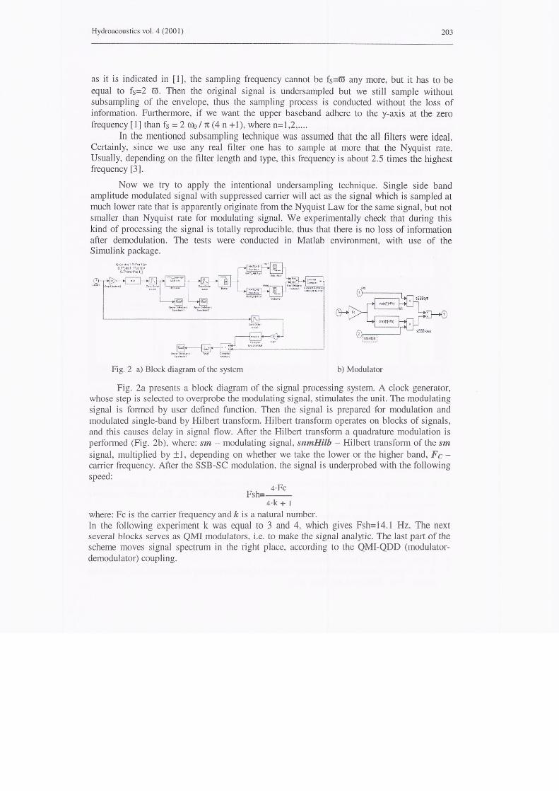
Fig. 2 a) Block diagram of the system b) Modulator
Fig. 2a presents a block diagram 01' the signal processing system. A clock generator,whose step is selected to overprobe the modulating signal, stimulates the unit. The modulatingsignal is formed by user defined function. Then the signal is prepared for modulation andmodulated single-band by Hilbert transform. Hilbert transform operates on blocks of signals,and this causes delay in signal tlow. After the Hilbert transform a quadrature modulation isperformed (Fig. 2b), where: sm - modulating signal, smnHilb - Hilbert transform of the smsignal, multiplied by ± J, depending on whether we take the lower or the higher band, Fc -carrier frequency. After the SSB-SC modulation, the signal is underprobed with the followingspeed:
4·FcFsh=--
4·k + I
where: Fe is the carrier frequency and k is a naturai number.In the following experiment kwas equal to 3 and 4, which gives Fsh= 14.1 Hz. The nextseveral blocks serves as QMI modulators, i.e. to make the signal analytic. The last part 01' thescheme moves signal spectrum in the right place, according to the QMI-QDD (modulator-demodulator) coupling.

204 P. Poćwiardowski,P. Kobylarz
2. RESULTS
We have tested the program with many sets of modulating signals and several valuesof the kparameter. The results achieved show the correspondence of simulation results withtheory. It can be seen, that for some signaIs (i.e. amplitude-modulated signals) it is possible toprobe them with lower frequency than twice the highest frequency of the signal. In fact, theminimum sampling frequency must be twice as high as the width of the band. So we canunderprobe the signal only if there are no other signals outside the specified band.
The results of three sinusoids gained together are presented in Fig. 3.
Fig. 3. Sample simulation resuts (upper figures present time waveforms, lower ones - its powerspectral density)
Apart from the above signals we tested many signals with different frequencies andamplitudes, and every time we got satisfactory results. The experiments show that input signalcan have any shape and it will be recovered without loss of information.
REFERENCES
1. E. Hermanowicz, Specjalne filtry o skończonej odpowiedzi impulsowej i ich zastosowaniedo modulacji i demodulacji kwadraturowej, ELEKTRONIKA Nr. 82, Zeszyty naukowePolitechniki Gdanskiej
2. A. Eliminowicz, Komputerowe modelowanie wąskopasmowego beamformera FFT, PraceXV Sympozjum z Hydroakustyki, Gdańsk-Jurata 26-29 Maja 1998,.
3. Knight et al., Digital Signal processing for sonar, Proceedings of the IEEE, Vol. 69, No.11, Nov. 1981,
4. I. Selin, Detection Theory, Princeton, 19655. A. S. Willsky, Relationships between digital signal processing and control and estimation
theory, Proc. IEEE, vol. 66, Sept 1978