single-slope concrete bridge...
TRANSCRIPT

TRANSPORTATION RESEARCH RECORD 1468 25
Single-Slope Concrete Bridge Rail
KING K. MAK, DON J. GRIPNE, AND CHARLES F. MCDEVITT
A single-slope concrete median barrier was previously designed, developed, and successfully crash tested at the Texas Transportation Institute in accordance with guidelines set forth in NCHRP Report 230. The Washington State Department of Transportation is interested in adapting this single-slope barrier design for use as a bridge rail. The re~ults of full-scale crash tests conducted on this single-slope concrete bndge rail and the evaluation of its impact performance are presented. The single-slope concrete bridge rail was judged to have successfully met all evaluation criteria set forth in NCHRP Report 350 and the 1989 AASHTO Guide Specifications for Bridge Railings and is recommended for field implementation.
A single-slope concrete median barrier was previously designed, developed, and successfully crash tested at the Texas Transportation Institute (TTI) in accordance with guidelines set forth by Beason et al. (J) and in NCHRP Report 230 (2). The barrier was approved by FHW A and was adopted by many states for field implementation. As implied by its name, this single-slope barrier has a single sloped face at 79 degrees (or 11 degrees to the vertical) and is 42 in. (1.07 m) high. The single-slope barrier has several advantages over the New Jersey safety-shaped barrier. First, the single-slope barrier has a lower propensity for causing rollover than the New Jersey safety-shaped barrier without greatly increasing the damage and lateral acceleration to impacting vehicles.
Second, although the initial construction cost of the single-slope barrier is comparable to that of standard safety-shaped barrier, the maintenance costs and life cycle costs of the single-slope barrier should be substantially lower than those of the standard safetyshaped barrier. To maintain the shape and height of the barrier for the standard safety-shaped barrier, the pavement surface must first be lowered before any overlay can be applied to provide a new wearing surface. This is an expensive outlay over the life of the pavement and the barrier. On the other hand, a single-slope barrier can accommodate overlays without any concern for the shape of the barrier. Also, with an initial height of 42 in. ( 1.07 m), the barrier can accommodate up to 10 in. (254 mm) of overlay, e.g., five overlays of 2 in. (51 mm) each over the years, and still has a height of 32 in. (0.81 m), which is the height of the standard safety-shaped barrier.
Third, the single-slope barrier can be advantageous in situations in which there are differences in elevation between the two sides of divided highways, such as at superelevated curves. Because there is only a single sloped face, the height of the barrier can be different on the two faces to accommodate the difference in elevation without concern over the shape of the barrier. This can simplify the construction of the barrier, especially when slip-forming is used.
The Washington State Department of Transportation (W aDOT) is interested in adapting this single-slope barrier design for use as a bridge rail. Although the single-slope barrier design was originally
K. K. Mak, Texas Transportation Institute, The Texas A&M University, College Station, Tex. 77843. D. J. Gripne, Washington Department of Transportation, Olympia, Wash. 98504-7300. C. F. McDevitt, FHWA, Turner-Fairbank Highway Research Center, McLean, Va. 22101.
intended for use as a median barrier, there is no reason why it could not be used as a bridge rail. The key difference between the median barrier and the bridge rail applications would be the height of the barrier, which is 42 in. (1.07 m) for the median barrier and 32 in. (0.81 m) for the bridge rail. On the basis of results of previous crash tests, the impact performance of the barrier should not be adversely affected when the barrier height is lowered from 42 to 32 in. ( 1.07 to 0.81 m). The other difference is that the bridge rail is tied into the bridge deck, whereas the median barrier is keyed in place with an asphalt overlay. However, because the barrier remains essentially rigid in both applications, there should not be any effect on its impact performance. It should be noted that although the bridge rail was tested at. a rail height of 32 in. (0.81 m), the bridge rail would perform satisfactorily at greater rail heights.
Presented in this paper are the results of full-scale crash tests conducted on this single-slope concrete bridge rail and the evaluation of its impact performance.
TEST INSTALLATION
A schematic of the test installation is shown in Figure 1. Precast single-slope median barrier sections, previously fabricated by TTI in another study, were used for the test installation. The use of the precast single-slope median barrier sections saved the expenses of building a simulated bridge deck and the bridge rail. The rationale for this approach was that as long as the barrier remained rigid it really would not matter whether the bridge rail was tied into a simulated bridge deck. The concern was more with the shape and geometrics of the single-slope bridge rail and not the strength of the rail or its tie-in to the bridge deck. A schematic showing the rebar and connection details planned for use with the single-slope bridge rail by WaDOT and approved by FHW A is shown in Figure 2. Note that the connection details are adopted from the standard safety-shaped concrete bridge rail, which has been successfully crash tested in previous studies and was therefore not evaluated in the present study.
Four 30-ft (9.14-m) precast barrier sections were used for a total installation length of 120 ft (36.6 m). The barrier sections were connected with channel connectors at the bottom, and rebar grids were placed in the grid slots and were grouted in place. A ditch 10 in. (254 mm) deep was dug for placement of the barrier sections so that the height of the barrier above ground level was reduced from 42 to 32 in, ( 1.07 to 0.81 m). The bottom of the ditch was lined with base materials to ensure that the foundation for the barrier was level and smooth. To ensure that the barrier sections would remain rigid during the impacts, the barrier section within which the impacts would occur was doweled into the existing concrete pavement with No. 5 rebars spaced at 3 ft (0.91 m) center to center. Also, after the barrier was installed in the ditch, the back of the barrier was keyed with a concrete overlay, 24 in. (0.61 m) wide and 4 in. (102 mm) thick, and the area between the existing concrete pavement and the front of the barrier was backfilled with grout to make sure that the barrier

26
Grouted Rebar Grid Connection
l 3T
Epoxy Seated Dowel
Concrete with Wire Mesh
TRANSPORTATION RESEARCH RECORD 1468
would remain rigid on impact. Photographs of the test installation are shown in Figure 3.
W aDOT plans to use a bridge rail height of 34 in. (0.86 m), which allows for a future overlay of 2 in. (51 mm). However, the crash tests were conducted with a bridge rail height of 32 in. (0.81 m) since the lower rail height was considered a more critical test condition. The schematic in Figure 2 showing the rebar and connection details is for a rail height of 32 in. (0.81 m), which was the rail height evaluated in the crash tests. However, the details for a 34-in. (0.86-m) single-slope bridge rail should be very similar.
CRASH TEST MATRIX
FIGURE 1 Single-slope concrete bridge rail test installation.
In accordance with requirements set forth in the 1989 AASHTO Guide Specifications for Bridge Railings (3) (hereinafter referred to
"6 Spacing at 7" TYP--.
i
IX)
I
i NI j
I I
i I I I i I I I
! ·I
•
•
I 6'/a" I 9Y2" I
'
,. •
1
.. r1 "4 Continuous with 2' -o" MIN splice
;....,_ _____ ......:/~ TYP
• •
•
•
11/z" Clearance
TYP
I
I
~I Q) i Ui
g_ i ~,
c;1 :::JI CT: WI
I"'\ I I
i ! •
~ I
I 10.8°
I • '--------+---' ----- • 5 at 1 6"
2 '/z" --i
• I • / --- •s at a"
/ ~ •s Spacing at ~1·.5:·:~nt;nuous w;th l'-2" TYP
2'-0" MIN splice space at 7" MAX TYP
FIGURE 2 Reinforcement and connection details planned for single-slope concrete bridge rail.

Mak et al.
FIGURE 3 Single-slope concrete bridge rail test installation.
as the Guide Specifications) for a Performance Level 2 bridge rail, the following three crash tests are required:
1. An 1,800-lb (817-kg) passenger car striking the bridge rail at a nominal speed and angle of 60 mph (96.6 km/hr) and 20 degrees,
2. A 5,400-lb (2,449-kg) pickup truck striking the bridge rail at a nominal speed and angle of 60 mph (96.6 km/hr) and 20 degrees, and
3. An 18,000-lb (8,170-kg) single-unit truck striking the bridge rail at 50 mph (80.5 km/hr) and 15 degrees.
The crash test matrix was modified for the testing of the singleslope concrete bridge railing. The 1,800-lb (817-kg) passenger car severity test was considered unnecessary and was deleted from the crash test matrix. As mentioned previously, the single-slope concrete median barrier successfully passed the large car structural adequacy test and the small car severity test in accordance with guidelines set forth in NCHRP Report 230 (2). On the basis of the results of those crash tests, it was believed that the barrier height would have little or no effect on the small car severity test and there was therefore no need to repeat the test.
As for the 5,400-lb (2,449-kg) pickup truck structural adequacy
27
test at 60 mph (96.6 km/hr) and 20 degrees, it should also perform similarly to the 4,500-lb (2,043-kg) passenger car test at 60 mph (96.6 km/hr) and 25 degrees. However, although the large car successfully met the guidelines set forth in NCHRP Report 230 (2), the vehicle exhibited a tendency to climb up on the barrier. There was therefore concern that vehicle stability might become a problem with the pickup truck when the barrier height was reduced from 42 to 32 in. ( 1.07 to 0.81 m). Thus, the crash test with the pickup truck was included. It was also decided that the test conditions for the pickup truck test would be in accordance with Test Level 4 of the new NCHRP Report 350 (4) requirements [i.e., a 2,000-kg (4,409-lb) pickup truck striking the bridge rail at a nominal speed and angle of 100 km/hr (62.2 mph) and 25 degrees].
In summary, the actual crash test matrix used to evaluate the impact performance of this single-slope concrete bridge rail design included only the pickup truck and the single-unit-truck crash tests. Testing and evaluation were performed in accordance with guidelines outlined in NCHRP Report 350 (4) and the 1989 AASHTO Guide Specifications (3).
FIGURE 4 Vehicle after Test 7147-15.

I
;. : : : 'ri.• ID : : : : : :
····~·····~·,-··~·····~·· : :' : :' :~~ ,. . . . ... . . . ... . . . ... . . . ... . . . ... . . . ... . . . ... . . . ... . . . ... . . . ...... . ~28.2m . . • . . . . . . . ·ifd .. -~· ... -~· ... -~- ... -~· ... -~· ... -~- ... -~- ... -~- ... -~- ...
General Information Test Agency ...... . Test No. . ........ . Date ............ .
Test Article Type ............ .
Installation Length (m) Size and/or dimension
and material of key elements ....... .
Soil Type and Condition .. Test Vehicle
Type ............ . Designation ....... . Model ........... . Mass (kg) Curb
Test Inertial Dummy Gross Static .
Texas Transportation Institute 7147-15 05/03/93
Bridge Rail Single Slope Concr·ete 36.6 (120 ft)
81 cm (32 in) high concrete N/A
Production Model 2000 p 1985 Chevrolet Custom 1,993 (4,390 lb) 2,000 (4,405 lbl 76 (167 lb) 2,076 (4,573 lb)
FIGURE 5 Results for Test 7147-15.
Impact Conditions Speed (km/h) ........... . Angle (deg) ............ .
Exit Conditions Speed (km/h) ........... . Angle (deg) ............ .
Occupant Risk Values Impact Velocity (m/s)
x-direction ........... . y-direction . . . . . . . . . . . .
THIV (optional) .......... . Ridedown Accelerations (g's)
x-direction ........... . y-direction . . . . . . . . . . . .
PHO (optional) .......... . ASI (optional) ........... . Max. 0.050-sec Averages (g'sl
x-direction y-direction z-direction
97 .2 (60.4 mi/hi 25.5
76.6 (47 .6 mi/h) 3.3
5.4 (17.7 ft/s) 7.8 (25.6 ft/s)
-6.1 -12.6
-7.3 -13.3 -5.6
Test Article Deflections (cm) Dynamic .......... . Permanent ......... .
Vehicle Damage Exterior
VOS ........... . CDC ........... .
Interior OCDI
Maximum Exterior Vehicle Crush (cm)
Max. Occ. Compart. Deformation (cm)
Post-Impact Behavior Max. Roll Angle (deg) Max. Pitch Angle (deg) Max. Yaw Angle (deg)
N/A 0.6 (0.3 in)
01RD5 01 FREK2 & 01RDEW2
RF0020000
41 (16.1 in)
13.9 (5.5 in)
30 7 40

Mak et al.
RESULTS OF CRASH TESTS
Pickup Truck Crash Test (Test 7147-15)
A 1985 Chevrolet C-20 Custom Deluxe pickup truck was used for the crash test. The test inertia weight of the vehicle was 2,000 kg (4,409 lb) and its gross static weight was 2,076 kg (4,577 lb), including an uninstrumented 50th percentile male anthropometric dummy restrained in the driver's seat with lap and shoulder belts.
The vehicle struck the bridge rail 12.2 m (40.0 ft) from the upstream end at a speed of 97.2 km/hr (60.4 mph) and an angle of 25 .5 degrees. The right front tire of the vehicle began to climb the face of the barrier on impact. Shortly thereafter the left front tire became airborne as the vehicle began to redirect. The rear of the vehicle then contacted the barrier, and shortly thereafter the rear wheels became airborne. The vehicle exited the harrier airborne, traveling at a speed of 76.5 km/hr (47.6 mph) and an angle of 3.3 degrees. The right front tire came back into contact with the pavement, and the tire and rim separated from the wheel hub subsequent to the impact with the pavement. The right rear tire and rim also separated from the wheel hub when the tire came back into contact with the pavement. The vehicle came to rest 77.4 m (254.0 ft) downstream and 21.2 m (69.5 ft) to the traffic side of the point of impact.
The barrier received only cosmetic damage (i.e., scrapes and tire marks), and there were two small cracks on the barrier. The vehicle was in contact with the barrier for 4.2 m (13.9 ft). The entire vehicle sustained extensive damage, as shown in Figure 4. Maximum deformation into the occupant compartment was 139 mm (5.5 in.) at the firewall area, and maximum exterior crush at the right front corner at bumper height of the vehicle was 410 mm (16.1 in). The right front wheel was pushed rearward 120 mm (4.7 in.), and the frame was bent.
The occupant risk factors were well within the preferred limits set forth in NCHRP Report 350 (4) and the Guide Specifications (3). In the longitudinal direction, occupant impact velocity was 5 .4 m/sec ( 17. 7 ft/sec), and the highest 0.010-sec average ridedown acceleration was -6.1 g. Lateral occupant impact velocity was 7.8 m/sec (25.6 ft/sec), and the highest 0.010-sec occupant ridedown acceleration was -12.6 g. A summary of the test results is provided in Figure 5.
Single-Unit-Truck Crash Tests (Tests 7147-16 and 7147-17)
A 1982 GMC single-unit truck with an empty weight of 5,262 kg (11,590 lb) was used for the second crash test (Test 7147-16). The vehicle was ballasted with sandbags to a test inertia and gross static weight of 8, 172 kg ( 18,000 lb). The vehicie struck the bridge rail 13.7 m (45.0 ft) from the upstream end at a speed of 82.1 km/hr (51.0 mph) and at an angle of 10 degrees. Shortly after impact with the bridge rail the front axle separated from the vehicle. The right lower corner and edge of the box van then set down on top of the rail and rode along in this fashion until the vehicle rode off the end of the bridge rail test installation. The box van reached a maximum roll angle of 23 degrees, and the cab reached a maximum roll angle of 25 degrees. The box van then began to right itself and came to rest upright 65.4 m (214.5 ft) downstream and 2.6 m
29
(8.5 ft) to the left of the point of impact (i.e., to the traffic side of the bridge rail).
The barrier received only cosmetic damage (i.e., gouges, scrapes, and tire marks). The vehicle was in contact with the barrier for 15.6 m (51.2 ft). The vehicle sustained extensive damage to the front suspension, as shown in Figure 6. Maximum crush at the right front corner of the vehicle was 178 mm (7.0 in.). The front axle was separated from the vehicle, and the spring shackles, U-bolts, shocks, mounts, tie rods, and steering arm were damaged. In addition, damage was sustained by the front bumper, the right front quarter-panel, and the right and left running boards. The windshield was cracked, and the fuel tank was scraped.
The occupant risk factors were well within the limits set forth in the Guide Specifications (3). In the longitudinal direction, occupant impact velocity was 2.3 m/sec (7 .5 ft/sec), and the highest 0.010-sec average ridedown acceleration was -1.3 g. Lateral occupant impact velocity was 3.5 m/sec (11.5 ft/sec), and the highest 0.010-sec occupant ridedown acceleration was -2.6 g. A summary of the test results is given in Figure 7.
FIGURE 6 Vehicle after Test 7147-16.

--~~~-L-~-=• =-:es_.•m_-_-_-_-_-_-_-_-_-__ :-.~~-.. -•. -.~-:---.~eJ:
General Information Test Agency ....... . Test No ............ . Date ............. .
Test Article Type ............. .
Installation Length (m) Size and/or dimension
and material of key elements ........ .
Soil Type and Condition Test Vehicle
Type ............. . Designation ........ . Model ............ . Mass (kg) Curb ..... .
Test Inertial . Dummy .... Gross Static .
Texas Transportation Institute 7147-16 05/06/93
Bridge Rail Single Slope Concrete 36.6 (120 ft)
81 cm (32 in) high concrete N/A
Production Model 8000 s 1982 GMC Single-Unit Truck 5,262 (11,590 lb) 8, 172 (18,000 lb) NIA 8,172 (18,000 !b)
FIGURE 7 Results for Test 7147-16.
Impact Conditions Speed (km/h) ............ . Angle (deg) ............. .
Exit Conditions Speed (km/h) ............ . Angle (deg) ............. .
Occupant Risk Values Impact Velocity (mis)
x-direction .. .- ......... . y-direction ............ .
THIV (optional) ........... . Ridedown Accelerations (g's)
x-direction ............ . y-direction ............ .
PHO (optional)· ........... . ASI (optional) ............ . Max. 0.050-sec Averages (g's)
x-direction ............ . y-direction z-direction
82.1 (51.0 mi/h) 10.0
NIA 0
2.3 (7.5ft/s) 3.5 (11.5 ft/s)
-1.3 -2.6
-1.3 -2.7 2.4
Test Article Deflections (cm) Dynamic .......... . Permanent ......... .
Vehicle Damage Exterior
VOS ............ . CDC
Interior OCDI
Maximum Exterior Vehicle Crush (cm) ..
Max. Occ. Compart. Deformation (cm)
Post-Impact Behavior Max. Roll Angle (deg) Max. Pitch Angle (deg) Max. Yaw Angle (deg) .
CU<t Ut WI U II rt I
NIA 0.2 (0.1 in)
RFOOOOOOO
17.8 (7.0 in)
0
19.8 -2.3 -8.2
Mak et al.
The vehicle struck the bridge rail at an angle of 10 degrees instead of the required 15 degrees. An extensive investigation revealed that the guidance cable release mechanism did not function properly, causing the front tires to tum to the left abruptly, which in tum caused the truck to yaw counterclockwise.
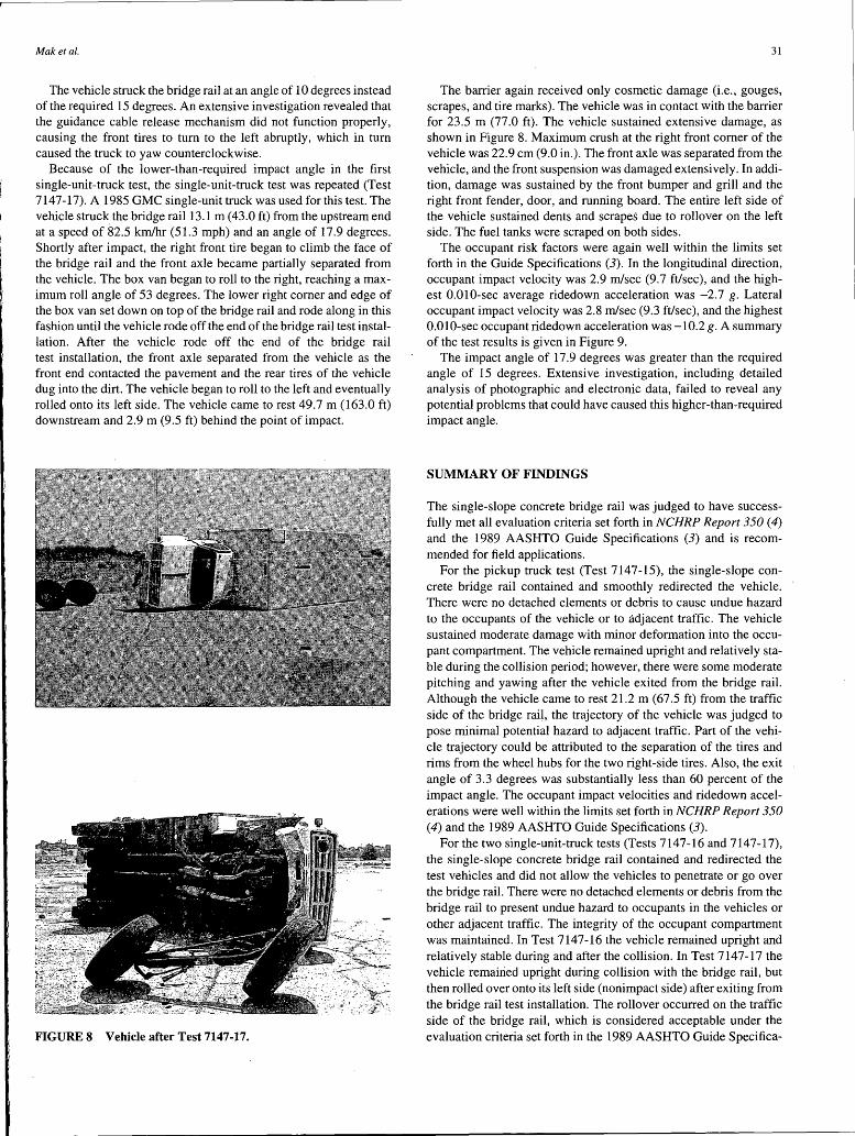
Because of the lower-than-required impact angle in the first single-unit-truck test, the single-unit-truck test was repeated (Test 7147-17). A 1985 GMC single-unit truck was used for this test. The vehicle struck the bridge rail 13.1 m ( 43.0 ft) from the upstream end at a speed of 82.5 km/hr (51.3 mph) and an angle of 17.9 degrees. Shortly after impact, the right front tire began to climb the face of the bridge rail and the front axle became partially separated from the vehicle. The box van began to roll to the right, reaching a maximum roll angle of 53 degrees. The lower right comer and edge of the box van set down on top of the bridge rail and rode along in this fashion until the vehicle rode off the end of the bridge rail test installation. After the vehicle rode off the end of the bridge rail test installation, the front axle separated from the vehicle as the front end contacted the pavement and the rear tires of the vehicle dug into the dirt. The vehicle began to roll to the left and eventually rolled onto its left side. The vehicle came to rest 49.7 m (163.0 ft) downstream and 2.9 m (9.5 ft) behind the point of impact.
FIGURE 8 Vehicle after Test 7147-17.
31
The barrier again received only cosmetic damage (i.e., gouges, scrapes, and tire marks). The vehicle was in contact with the barrier for 23.5 m (77.0 ft). The vehicle sustained extensive damage, as shown in Figure 8. Maximum crush at the right front comer of the vehicle was 22.9 cm (9.0 in.). The front axle was separated from the vehicle, and the front suspension was damaged extensively. In addition, damage was sustained by the front bumper and grill and the right front fender, door, and running board. The entire left side of the vehicle sustained dents and scrapes due to rollover on the left side. The fuel tanks were scraped on both sides.
The occupant risk factors were again well within the limits set forth in the Guide Specifications (3). In the longitudinal direction, occupant impact velocity was 2.9 m/sec (9.7 ft/sec), and the highest 0.010-sec average ridedown acceleration was -2.7 g. Lateral occupant impact velocity was 2.8 m/sec (9.3 ft/sec), and the highest 0.010-sec occupant ridedown acceleration was-10.2 g. A summary of the test results is given in Figure 9.
The impact angle of 17 .9 degrees was greater than the required angle of 15 degrees. Extensive investigation, including detailed analysis of photographic and electronic data, failed to reveal any potential problems that could have caused this higher-than-required impact angle.
SUMMARY OF FINDINGS
The single-slope concrete bridge rail was judged to have successfully met all evaluation criteria set forth in NCHRP Report 350 (4) and the 1989 AASHTO Guide Specifications (3) and is recommended for field applications.
For the pickup truck test (Test 714 7-15), the single-slope concrete bridge rail contained and smoothly redirected the vehicle. There were no detached elements or debris to cause undue hazard to the occupants of the vehicle or to adjacent traffic. The vehicle sustained moderate damage with minor deformation into the occupant compartment. The vehicle remained upright and relatively stable during the collision period; however, there were some moderate pitching and yawing after the vehicle exited from the bridge rail. Although the vehicle came to rest 21.2 m (67.5 ft) from the traffic side of the bridge rail, the trajectory of the vehicle was judged to pose minimal potential hazard to adjacent traffic. Part of the vehicle trajectory could be attributed to the separation of the tires and rims from the wheel hubs for the two right-side tires. Also, the exit angle of 3.3 degrees was substantially less than 60 percent of the impact angle. The occupant impact velocities and ridedown accelerations were well within the limits set forth in NCHRP Report 350 (4) and the 1989 AASHTO Guide Specifications (3).
For the two single-unit-truck tests (Tests 7147-16 and 7147-17), the single-slope concrete bridge rail contained and redirected the test vehicles and did not allow the vehicles to penetrate or go over the bridge rail. There were no detached elements or debris from the bridge rail to present undue hazard to occupants in the vehicles or other adjacent traffic. The integrity of the occupant compartment was maintained. In Test 7147-16 the vehicle remained upright and relatively stable during and after the collision. In Test 7147-17 the vehicle remained upright during collision with the bridge rail, but then rolled over onto its left side (nonimpact side) after exiting from the bridge rail test installation. The rollover occurred on the traffic side of the bridge rail, which is considered acceptable under the evaluation criteria set forth in the 1989 AASHTO Guide Specifica-

General Information Test Agency ...... . Test No. . ........ . Date ............ .
Test Article Type ............ .
Installation Length (ml Size and/or dimension
and material of key elements ....... .
Soil Type and Condition .. Test Vehicle
Type ............ . Designation ....... . Model ........... . Mass (kgl Curb
Test Inertial Dummy Gross Static .
Texas Transportation Institute 7147-17 05/06/93
Bridge Rail Single Slope Concrete 36.6 (120 ftl
81 cm (32 inl high concrete N/A
Production Model 8000 s 1985 GMC Single-Unit Truck 5,207 (11,470 lbl 8, 172 (18,000 lb) N/A 8, 172 (18,000 lb)
FIGURE 9 Results for Test 7147-17.
Impact Conditions Speed (km/h) ........... . Angle (deg) ............ .
Exit Conditions Speed (km/h) ........... . Angle (deg) ............ .
Occupant Risk Values Impact Velocity (m/s)
x-direction ........... . y-direction ........... .
THIV (optional) .......... . Ridedown Accelerations (g's)
x-direction ........... . y-direction ........... .
PHO (optional) .......... . ASI (optional) ........... . Max. 0.050-sec Averages (g's)
x-direction ............ . y-direction ........... . z-direction
I ,-Ir\ I "j . ·' -··"· , ..... , ....
·: ~~~ .. '@:'. ................. .
Test Article Deflections 82.5 (51 .3 mi/h) (cml 17.9 Dynamic .......... N/A
Permanent . ........ 0.2 (0.1 in) N/A 0 Vehicle Damage
Exterior VOS ...........
2.9 (9.7 ft/s) CDC ........... 2.8 (9.3 ft/s)
Interior OCDI ........... RFOOOOOOO
-2.7 Maximum Exterior -10.2 Vehicle Crush (cm)
Max. Occ. Compart. Deformation (cm)
-2.0 Post-Impact Behavior -5.6 Max. Roll Angle (deg) 53.0 -1.4 Max. Pitch Angle (deg) 4.3
Max. Yaw Angle (deg) -18.9

Mak et al.
tions (3). The vehicle trajectory did not pose any potential hazard to adjacent traffic in either test.
The impact angles for the two single-unit-truck tests were too low (10 degrees) in the first test and too high (17.9 degrees) in the second test. However, because both tests successfully met all evaluation criteria, it is reasonable to argue that the single-slope concrete bridge rail would have performed satisfactorily had the impact angle been at the required 15 degrees. A review of the two tests showed that, for the test with the higher impact angle, the vehicle was less stable with a much higher roll angle toward the barrier and a slightly higher climb on the barrier during impact with the bridge rail. Of course, the vehicle rolled over after exiting from the bridge rail in the test with the higher impact angle.
33
REFERENCES
1. Beason, W. L., H. E. Ross, Jr., H. S. Perera, and W. L. Campise. Development of a Single Slope Concrete Median Barrier. Final Report 9429C-1. Texas State Department of Highways and Public Transportation, Austin, Feb. 1989.
2. Michie, J. D. NCHRP Report 230: Recommended Procedures for the Safety Performance Evaluation of Highway Appurtenances. TRB, National Research Council, Washington, D.C., March 1981.
3. Guide Specifications for Bridge Railings. AASHTO, Washington, D.C., 1989.
4. Ross, H. E., Jr., D. L. Sicking, R. A. Zimmer, and J. D. Michie. NCHRP Report 350: Recommended Procedures for the Safety Performance Evaluation of Highway Features. TRB, National Research Council, Washington, D.C., 1993.