single slot smt connectors for card-bus based … sheets/hirose pdfs/ic11s.pdf · pop-up button...
TRANSCRIPT

A2
Single Slot SMT Connectors For Card-Bus Based PC CardsIC11S Series PC Card Standard Compliant
Reduced height : 5.6mm high
Wide variety of options
(1)Board Mounting➀ Standard type➁ Reverse type
(2)Types of eject button➀ Rigid button➁ Foldering button➂ Pop-up button
(3)Position of eject buttons➀ Right➁ Left
(4)Standoffs➀ None➁ 2.2mm
■ Features1. PC Card Standard compliant:
• Grounding is required to meet the high speed signalrequrements of the PC card standard. Grounding reliability isachieved with a grounding plate and 8 grounding contacts.
• Type 1, type 2 and type 3 cards are covered.• Terminals for ground clipping are provided.
2. Space savingSmaller size reduces occupied area on PC boards ascompared to previous products.
3. Reduced Height:Connector height is minimized to 5.6mm, making possiblethinner product designs.
4. Eject mechanism with high-level functionalityHirose Electric's original ejection mechanism provides anhigher degree of card ejection over existing products. Thisimproves the operational qualities of card removal. (Patentspending)
5. Wide Variety of Options Available• Standard type mounts to the top of the PC board and reversetype mounts on the underside of the board
• Three types of eject buttons; rigid, flexible and POP-UP.Alltypes can be installed on the right or left side of the ejector.
• Available with standoff to utilize space under the connector formounting other parts.
6. Light-weightWeight of 12.7g for normal button type helps achieve thereduced weight required in today’s products.
A3
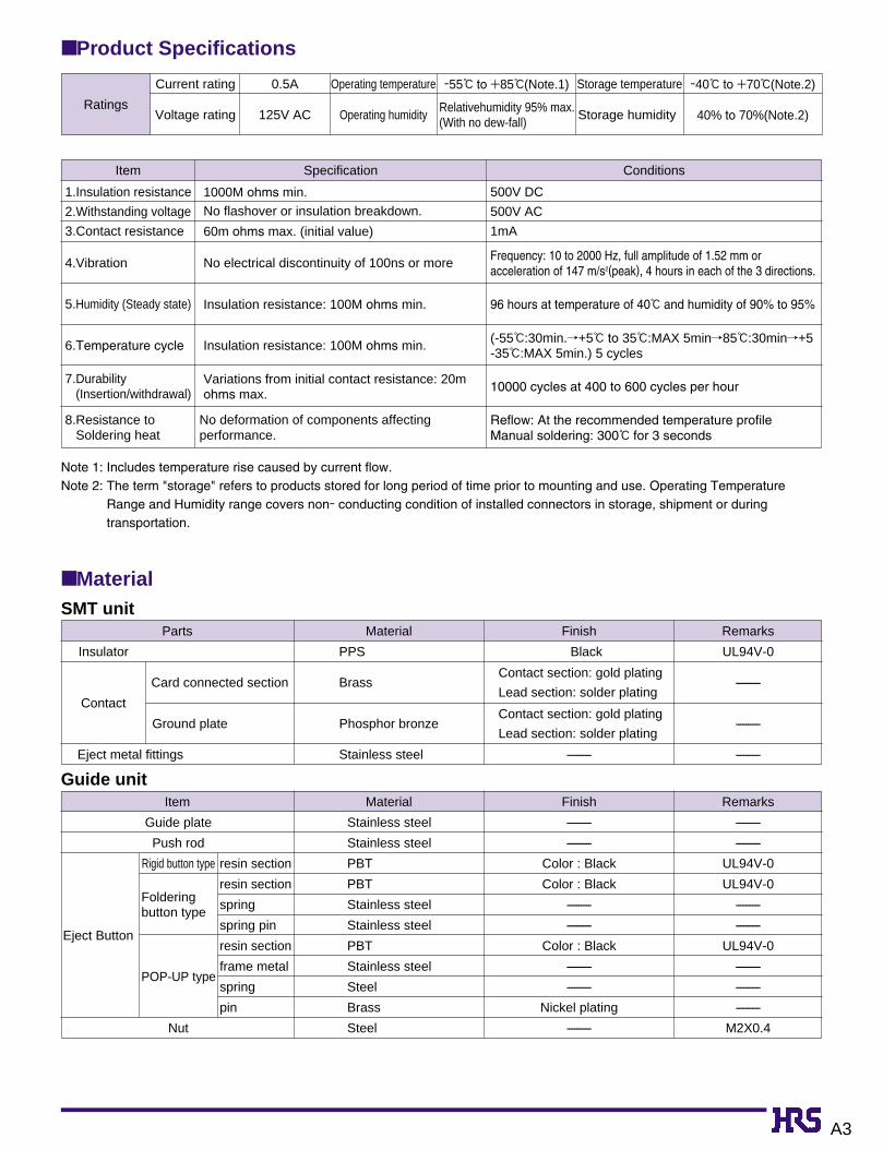
■ Product Specifications
■ MaterialSMT unit
Parts
Insulator
Ground plate
Card connected section
Eject metal fittings
Contact
Material Finish
Finish
Remarks
Remarks
PPS
Stainless steel
Phosphor bronze
Brass
Contact section: gold plating
Lead section: solder plating
----------
Contact section: gold plating
Lead section: solder plating
Black UL94V-0
----------
----------
----------
Item
Guide plate
Push rod
Eject Button
Rigid button type resin section
resin section
spring
spring pin
resin section
frame metal
spring
pin
Folderingbutton type
POP-UP type
Nut
Stainless steel
Stainless steel
PBT
PBT
Stainless steel
Stainless steel
PBT
Stainless steel
Steel
Brass
Steel
----------
----------
Color : Black
Color : Black
----------
----------
Color : Black
----------
----------
Nickel plating
----------
----------
----------
UL94V-0
UL94V-0
----------
----------
UL94V-0
----------
----------
----------
M2X0.4
Material
Item
1.Insulation resistance
2.Withstanding voltage
3.Contact resistance
5.Humidity (Steady state)
4.Vibration
6.Temperature cycle
7.Durability(Insertion/withdrawal)
8.Resistance toSoldering heat
Specification Conditions
1000M ohms min.No flashover or insulation breakdown.
60m ohms max. (initial value)
Insulation resistance: 100M ohms min.
No electrical discontinuity of 100ns or more
Insulation resistance: 100M ohms min.
Variations from initial contact resistance: 20mohms max.
No deformation of components affectingperformance.
500V DC
500V AC
1mA
(-55ç:30min./+5ç to 35ç:MAX 5min/85ç:30min/+5-35ç:MAX 5min.) 5 cycles
96 hours at temperature of 40ç and humidity of 90% to 95%
10000 cycles at 400 to 600 cycles per hour
Reflow: At the recommended temperature profileManual soldering: 300ç for 3 seconds
Frequency: 10 to 2000 Hz, full amplitude of 1.52 mm oracceleration of 147 m/s2(peak), 4 hours in each of the 3 directions.
Note 1: Includes temperature rise caused by current flow.Note 2: The term "storage" refers to products stored for long period of time prior to mounting and use. Operating Temperature
Range and Humidity range covers non- conducting condition of installed connectors in storage, shipment or duringtransportation.
Guide unit
Ratings
Current rating 0.5A Operating temperature -55ç to +85ç(Note.1) Storage temperature -40ç to +70ç(Note.2)
Voltage rating 125V AC Operating humidityRelativehumidity 95% max.(With no dew-fall)
Storage humidity 40% to 70%(Note.2)

A4
(Note.) IC11S Series will be used in combination of SMT unit with guide unit. When using, please selectthe same type for the following items. Please note that other combinations cannot be used.
Board Mounting Type:PL : standard typePLR : reverse type
Number of contacts : 68
Standoff type Blank : noneA : 2.2mm
Series name : IC11S 1.27SF : 1.27mm pitch SMT connector
With ejectorEJ : with ejector
Eject button positions R : rightL : left
1 5
6
7
2
3
4
IC11S A - 68 PLR - 1.27SF - EJ R1 2 3 6 74 5
■ Ordering Information
SMT Unit
Guide Unit
Board Mounting Type BD : standard typeBUR : reverse type
Standoff type Blank: none
A : 2.2mm
Series name : IC11S Eject button type EJ : rigid buttonFEJ : Foldering buttonPEJ : POP-UP button
Eject button positions R : rightL : left
8 11
12
9
10
IC11S A - BUR - FEJ R8 9 1210 11
• Series name ( ⇔ )• Standoff ( ⇔ )• Board-installed type ( ⇔ )• Eject button positions ( ⇔ )
1 8
2 9
4 107 12

A5
Note.1) This figure illustrates grouping of SMT unit(➀ ) and guide unit(➁ ) together.Note.2) Dimensions for card fitting are in accordance with "PC Card Standard".Note.3) Indicated dimensions are symmetrical to the center of the card insertion slot.
■ StandardRight rigid button type
Standofftype
none
2.2mm
640-1007-3
640-1009-9
IC11S-68PL-1.27SF-EJR
IC11SA-68PL-1.27SF-EJR
640-1071-2
640-1073-8
IC11S-BD-EJR
IC11SA-BD-EJR
3
5.2
5.6
7.8
0.1
2.3
12.7
13.1
➀ SMT unit
CL No.Part Number
➁ Guide unit A(mm)
B(mm)
C(mm)
Weight(g)CL No.Part Number
51.5
20.5
5.9
7.4
72No.1
No.2
No.36
No.68
No.34GNDGND
No.35
54.9 (18.
6) (27.
6)
59
P U
S HP
U S
H
C
42.545
P=0.635
34.4 MAX
eject metal fittings movable range
85.6
: in
card
inse
rtio
n
stro
ke:9
SMT unit ( )
7MAX
10M
AX
( 34.9)
59.5
6
A
3
3
3
1
guide unit ( )2
No.1 No.2
No.36 No.68
No.34
No.35
B
A
4.8

A6
Note.1) This figure illustrates grouping of SMT unit(➀ ) and guide unit(➁ ) together.Note.2) Dimensions for card fitting are in accordance with "PC Card Standard".Note.3) Indicated dimensions are symmetrical to the center of the card insertion slot.
■ StandardLeft rigid button type
Standofftype
none
2.2mm
640-1008-6
640-1010-8
IC11S-68PL-1.27SF-EJL
IC11SA-68PL-1.27SF-EJL
640-1072-5
640-1074-0
IC11S-BD-EJL
IC11SA-BD-EJL
3
5.2
5.6
7.8
0.1
2.3
12.7
13.1
➀ SMT unit
CL No.Part Number
➁ Guide unit A(mm)
B(mm)
C(mm)
Weight(g)CL No.Part Number
No.1
No.35 No.36
No.2 No.34
No.68
4.8
A B
eject metal fittings movable range
SMT unit ( )1
guide unit ( )2
85.6
: in
card
inse
rtio
n
GND
No.1
No.36
No.2
No.35
59
No.34
No.68
GND
7.4
72
51.5
20.5
5.9
(27.
6)
(18.
6)P
U S
HP U
S H
P= 0.635
42.545
59.5
34.4MAX
7MA
X10
MA
X
6
( 34.9 )
C
A
54.9
3
3
3
stro
ke:9
A7
Note.1) This figure illustrates grouping of SMT unit(➀ ) and guide unit(➁ ) together.Note.2) Dimensions for card fitting are in accordance with "PC Card Standard".Note.3) Indicated dimensions are symmetrical to the center of the card insertion slot.
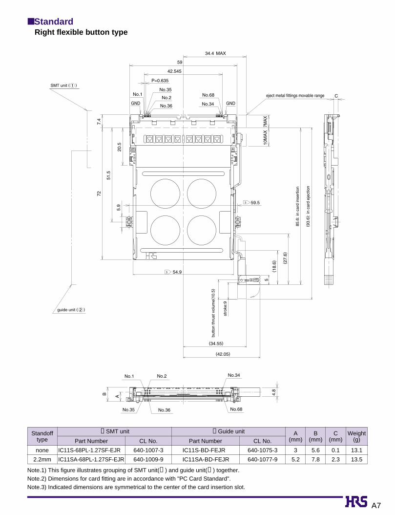
■ StandardRight flexible button type
Standofftype
none
2.2mm
640-1007-3
640-1009-9
IC11S-68PL-1.27SF-EJR
IC11SA-68PL-1.27SF-EJR
640-1075-3
640-1077-9
IC11S-BD-FEJR
IC11SA-BD-FEJR
3
5.2
5.6
7.8
0.1
2.3
13.1
13.5
➀ SMT unit
CL No.Part Number
➁ Guide unit A(mm)
B(mm)
C(mm)
Weight(g)CL No.Part Number
guide unit ( )2
eject metal fittings movable range
stro
ke:9
butto
n th
rust
vol
ume(
10.5
)
54.9
No.1
No.35
No.2
No.36
No.34
No.68
7.4
20.5
51.5
72
5.9
GND
No.1
No.36
No.2
No.35
59
No.34
No.68
GND
(27.
6)
(18.
6)
P U
S H
P U
S H
C
5
(34.55)
(42.05)
B A 4.8
59.5
P=0.635
42.545
34.4 MAX
7MA
X10
MA
X
A
A
3
3
SMT unit ( )1
85.6
: in
card
inse
rtio
n
(93.
6): i
n ca
rd e
ject
ion

A8
Note.1) This figure illustrates grouping of SMT unit(➀ ) and guide unit(➁ ) together.Note.2) Dimensions for card fitting are in accordance with "PC Card Standard".Note.3) Indicated dimensions are symmetrical to the center of the card insertion slot.
■ StandardLeft flexible. button type
Standofftype
none
2.2mm
640-1008-6
640-1010-8
IC11S-68PL-1.27SF-EJL
IC11SA-68PL-1.27SF-EJL
640-1076-6
640-1078-1
IC11S-BD-FEJL
IC11SA-BD-FEJL
3
5.2
5.6
7.8
0.1
2.3
13.1
13.5
➀ SMT unit
CL No.Part Number
➁ Guide unit A(mm)
B(mm)
C(mm)
Weight(g)CL No.Part Number
SMT unit ( )1
guide unit ( )2
eject metal fittings movable range
85.6
: in
card
inse
rtio
n
(93.
6): i
n ca
rd e
ject
ion
butto
n th
rust
vol
ume(
10.5
)
GND
No.1 No.35
No.2
No.36
59
No.68
No.34 GND
7.4
72
51.5
20.5
5.9
(18.
6)
54.9
P U
S H
P U
S H
7 M
AX
10 M
AX
34.4MAX
P=0.635
42.545
59.5
C
(27.
6)
5
(34.55)
(42.05)
A
3
3
3
stro
ke:9
No.1
No.35 No.36
No.2 No.34
No.68
4.8
A B

A9
■ StandardRight POP-UP button type
Standofftype
none
2.2mm
640-1007-3
640-1009-9
IC11S-68PL-1.27SF-EJR
IC11SA-68PL-1.27SF-EJR
640-1081-6
640-1083-1
IC11S-BD-PEJR
IC11SA-BD-PEJR
3
5.2
5.7
7.9
0.1
2.3
14.7
15.1
➀ SMT unit
CL No.Part Number
➁ Guide unit A(mm)
B(mm)
C(mm)
Weight(g)CL No.Part Number
Note.1) This figure illustrates grouping of SMT unit(➀ ) and guide unit(➁ ) together.Note.2) Dimensions for card fitting are in accordance with "PC Card Standard".Note.3) Indicated dimensions are symmetrical to the center of the card insertion slot.
SMT unit ( )1
guide unit ( )2
eject metal fittings movable range
84.5
(but
ton
thru
st p
ositi
on)
86.4
(but
ton
stor
ed p
ositi
on)
9.1(
Pop
-up
volu
me)
DR
No.35 No.36
No.2No.1
No.68
No.34
727.
4
51.5
20.5
5.9
54.9
GNDNo.68
No.34
59
No.2
No.35
No.36GND
No.1
P U
S H
P U
S H
B A
5
(35.1)
5
59.5
10M
AX
7MA
X
C
34.4 MAX
42.545
P= 0.635
A
A
3
3
3

A10
■ StandardLeft POP-UP button type
Standofftype
none
2.2mm
640-1008-6
640-1010-8
IC11S-68PL-1.27SF-EJL
IC11SA-68PL-1.27SF-EJL
640-1082-9
640-1084-4
IC11S-BD-PEJL
IC11SA-BD-PEJL
3
5.2
5.7
7.9
0.1
2.3
14.7
15.1
➀ SMT unit
CL No.Part Number
➁ Guide unit A(mm)
A(mm)
C(mm)
Weight(g)CL No.Part Number
Note.1) This figure illustrates grouping of SMT unit(➀ ) and guide unit(➁ ) together.Note.2) Dimensions for card fitting are in accordance with "PC Card Standard".Note.3) Indicated dimensions are symmetrical to the center of the card insertion slot.
SMT unit ( )1
guide unit ( )2
eject metal fittings movable range86
.4(b
utto
n st
ored
pos
ition
)
84.5
(but
ton
thru
st p
ositi
on)
9.1(
Pop
-up
volu
me)
DL
No.1
No.35
No.2
No.36 No.68
No.34
54.972
7.4
51.5
20.5
5.9
GNDNo.34
No.68
No.36
No.35
No.2No.1
GND
59
C
5 BA
5
(35.1)
59.5
P= 0.635
42.545
34.4 MAX
7MAX
10M
AX
A
P U
S HP
U S
H
3
3
3

A11
Note.1) This figure illustrates grouping of SMT unit(➀ ) and guide unit(➁ ) together.Note.2) Dimensions for card fitting are in accordance with "PC Card Standard".Note.3) Indicated dimensions are symmetrical to the center of the card insertion slot.
■ ReverseRight rigid button type
Standofftype
none
2.2mm
640-1003-2
640-1005-8
IC11S-68PLR-1.27SF-EJR
IC11SA-68PLR-1.27SF-EJR
640-1055-6
640-1057-1
IC11S-BUR-EJR
IC11SA-BUR-EJR
2.7
4.9
5.6
7.8
0.1
2.3
13.1
13.6
➀ SMT unit
CL No.Part Number
➁ Guide unit A(mm)
B(mm)
C(mm)
Weight(g)CL No.Part Number
guide unit ( )2
eject metal fittings movable range
85.6
: in
card
inse
rtio
n
51.5
(18.
6)
59
672
20.5
5.9
54.9
No.1No.35
No.2
No.36GNDGND
No.68 No.34
P U
S H
P U
S H
C
(27.
6)
6
(34.9)
7MAX
10M
AX
34.4 MAX
42.545
P=0.635
59.5
A
3
3
3
SMT unit ( )1
stro
ke:9
No.1
No.35
No.2
No.36
No.34
No.68
AB 4.8

A12
Note.1) This figure illustrates grouping of SMT unit(➀ ) and guide unit(➁ ) together.Note.2) Dimensions for card fitting are in accordance with "PC Card Standard".Note.3) Indicated dimensions are symmetrical to the center of the card insertion slot.
■ ReverseLeft rigid button type
Standofftype
none
2.2mm
640-1004-5
640-1006-0
IC11S-68PLR-1.27SF-EJL
IC11SA-68PLR-1.27SF-EJL
640-1056-9
640-1058-4
IC11S-BUR-EJL
IC11SA-BUR-EJL
2.7
4.9
5.6
7.8
0.1
2.3
13.1
13.6
➀ SMT unit
CL No.Part Number
➁ Guide unit A(mm)
B(mm)
C(mm)
Weight(g)CL No.Part Number
SMT unit ( )1
guide unit ( )2
eject metal fittings movable range
59
No.35
No.36
No.2
GND
No.1
No.34
No.68
GND
54.9
BA
(18.
6)
5.9
72
51.5
20.5
6
No.1
No.35
No.2
No.36
No.34
No.68
P U
S H
P U
S H
42.545
P= 0.635
4.8
(27.
6)
59.5
34.4 MAX
7MAX
10M
AX
C
6
(34.9)
A
3
3
3
85.6
: in
card
inse
rtio
n

A13
Note.1) This figure illustrates grouping of SMT unit(➀ ) and guide unit(➁ ) together.Note.2) Dimensions for card fitting are in accordance with "PC Card Standard".Note.3) Indicated dimensions are symmetrical to the center of the card insertion slot.
■ ReverseRight flexible button type
Standofftype
none
2.2mm
640-1003-2
640-1005-8
IC11S-68PLR-1.27SF-EJR
IC11SA-68PLR-1.27SF-EJR
640-1059-7
640-1061-9
IC11S-BUR-FEJR
IC11SA-BUR-FEJR
2.7
4.9
5.6
7.8
0.1
2.3
13.5
14
➀ SMT unit
CL No.Part Number
➁ Guide unit A(mm)
B(mm)
C(mm)
Weight(g)CL No.Part Number
SMT unit ( )1
guide unit ( )2
eject metal fittings movable range
85.6
: in
card
inse
rtio
n
93.6
: in
card
eje
ctio
n
butto
n th
rust
:(10
.5)
stro
ke:9
B A
72
51.5
20.5
5.9
6
59
No.35
No.36
No.2 GND
No.1No.34
No.68
GND
(18.
6)54.9
No.1
No.35
No.2
No.36
No.34
No.68
P U
S H
P U
S H
4.8
42.545
34.4 MAX
P= 0.635
10M
AX
7MA
X
59.5
(27.
6)
C
5
( 34.55)
( 42.05)
A
A
3
3
3
A14
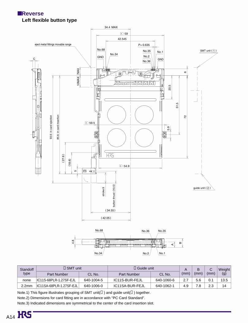
Note.1) This figure illustrates grouping of SMT unit(➀ ) and guide unit(➁ ) together.Note.2) Dimensions for card fitting are in accordance with "PC Card Standard".Note.3) Indicated dimensions are symmetrical to the center of the card insertion slot.
■ ReverseLeft flexible button type
Standofftype
none
2.2mm
640-1004-5
640-1006-0
IC11S-68PLR-1.27SF-EJL
IC11SA-68PLR-1.27SF-EJL
640-1060-6
640-1062-1
IC11S-BUR-FEJL
IC11SA-BUR-FEJL
2.7
4.9
5.6
7.8
0.1
2.3
13.5
14
➀ SMT unit
CL No.Part Number
➁ Guide unit A(mm)
B(mm)
C(mm)
Weight(g)CL No.Part Number
eject metal fittings movable range
SMT unit ( )1
guide unit ( )2
stro
ke:9
butto
n th
rust
:(10
.5)
93.6
: in
card
eje
ctio
n
85.6
: in
card
inse
rtio
nGND
No.68
No.34
59
No.35
No.36
No.2
No.1
GND
54.9
No.68
No.34
No.36
No.2 No.1
No.35
B
A
(18.
6)
6
20.5
51.5
72
5.9
P U
S H
P U
S H
42.545
P= 0.635
( 42.05 )
( 34.55 )
5
(27.
6)
59.5
10M
AX
7MAX
C
34.4 MAX
4.8
A
3
3
3
A15
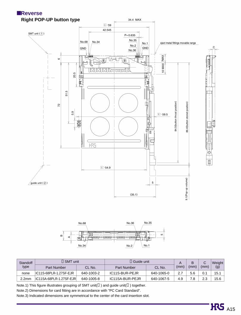
■ ReverseRight POP-UP button type
Standofftype
none
2.2mm
640-1003-2
640-1005-8
IC11S-68PLR-1.27SF-EJR
IC11SA-68PLR-1.27SF-EJR
640-1065-0
640-1067-5
IC11S-BUR-PEJR
IC11SA-BUR-PEJR
2.7
4.9
5.6
7.8
0.1
2.3
15.1
15.6
➀ SMT unit
CL No.Part Number
➁ Guide unit A(mm)
B(mm)
C(mm)
Weight(g)CL No.Part Number
Note.1) This figure illustrates grouping of SMT unit(➀ ) and guide unit(➁ ) together.Note.2) Dimensions for card fitting are in accordance with "PC Card Standard".Note.3) Indicated dimensions are symmetrical to the center of the card insertion slot.
guide unit ( )2
eject metal fittings movable range
84.5
(but
ton
thru
st p
ositi
on)
86.4
(but
ton
stor
ed p
ositi
on)
P U
S H
P U
S H
No.35No.36
No.1No.2No.34
No.68
AB72
5.9
51.5
20.5
6
GND
No.68 No.34
59
No.35
No.36
UR
No.2GND
No.1
54.9
A
5
42.545
34.4 MAX
P= 0.635
10 M
AX
7MA
X
59.5
C
(35.1)
5
A
3
3
3
SMT unit ( )1
9.1(
Pop
-up
volu
me)

A16
■ ReverseLeft POP-UP button type
Standofftype
none
2.2mm
640-1004-5
640-1006-0
IC11S-68PLR-1.27SF-EJL
IC11SA-68PLR-1.27SF-EJL
640-1066-2
640-1068-8
IC11S-BUR-PEJL
IC11SA-BUR-PEJL
2.7
4.9
5.6
7.8
0.1
2.3
15.1
15.6
➀ SMT unit
CL No.Part Number
➁ Guide unit A(mm)
B(mm)
C(mm)
Weight(g)CL No.Part Number
Note.1) This figure illustrates grouping of SMT unit(➀ ) and guide unit(➁ ) together.Note.2) Dimensions for card fitting are in accordance with "PC Card Standard".Note.3) Indicated dimensions are symmetrical to the center of the card insertion slot.
9.1(
Pop
-up
volu
me)
UL
GND
No.68
No.34
59
No.35
No.2
No.36 GND
No.1
6
20.5
51.5
5.9
72
No.68
No.34
No.36
No.2
No.35
No.1
A
B
P U
S H
P U
S H
C
10M
AX
7MAX
42.545
34.4MAX
P= 0.635
59.5
5
5
(35.1)
A
3
3
SMT unit ( )1
guide unit ( )2
eject metal fittings movable range
86.4
(but
ton
stor
ed p
ositi
on)
84.5
(but
ton
thru
st p
ositi
on)

A17
■ PCB mounting pattern
● Standard Type
● Without standoff(right button)
● Standoff 2.2mm(common to both right and left buttons)
● Without standoff(left button)
installed section
30 MIN0.
8MA
X
0.3M
IN0.
8MAX
28.5
MIN
26.8
MIN
26.8
MIN
28.5
MIN
31.4
MIN
31.4
MIN
7MIN
21M
IN
21M
IN7M
IN0.
8MAX
1.6M
AX
1.6M
AX0.
3MIN
(6.6
)17
.9M
IN
30 MIN
card edge position
52.8±0.05
4.75±0.05 54.75±0.05 54.75±0.05
58.1
±0.
05
58.1
±0.
05 4.75±0.05
34.5 MIN 34.5 MIN 30 MIN
30 MAX52.8±0.05
48.5MAX2 48.5MAX2
installed section
0.8M
AX
(6.6
)
17.9
MIN
card edge position
shielded board-pressed areshielded board-pressed area
2-Ø2.2 +0.1+02-Ø2.2 +0.1
+0
55.9MIN
3.05MIN27.95MAX34.5MIN
3.05MIN27.95MAX34.5MIN
2MIN 2MIN
2
1
59.5±0.05
52.8±0.05
54.75±0.0547.5±0.05
(6.6
)58
.1±
0.05
7MIN
2MIN 3.05MIN
2
55.9MIN2
59.5±0.052
installed section
22.6
MA
X27
.6M
INcard edge position
50.6MAX2
56.85MAX2
59.5MAX2
shielded board-pressed area
2-Ø2.2 +0.1+0
parts installation-prohibited area
Note.1) area and area show the pattern-inhibited area.However area will be the pattern-inhibited area only when guide unit is "IC11S-BD-PEJ✽ ".
Note.2) Indicated dimensions are symmetrical to the center of the card insertion slot.

A18
BPCB mounting pattern (Enlarged)
3±0.
1
1.4±
0.1
3.7275±0.05
48±0.05
46.2725±0.05
1.2±
0.1
2±0.
1
3±0.
1
1.4±
0.1
68-0.37±0.03
P=0.635±0.03
1.9±0.1
2±0.05
No.1
No.2
No.68
No.34
No.35
Ø1.3
±0.05
Ø1.3±0.05
GNDGND
● Standard type

A19
● Reverse Type
installed section
installed section
2MA
X(5
.2)
15.2
MIN
56.7
±0.
05
30.2
5±0.
0518
.45±
0.05
14.7
5±0.
0520
.25±
0.05
4.75
±0.
053.
925±
0.05
4.75±0.05 54.75±0.05
52.8±0.05
12-2
MIN
card edge position
60MIN2
50.8MAX
27.95MAX34.5MIN
3.05MIN 2MIN7M
IN
26.8
MIN
21.2
MA
X
26.2
MIN
26.8
MIN 7M
IN
4.75
±0.0
520
.25±
0.05
18.4
5±0.
0530
.25±
0.05
14.7
5±0.
053.9
25±0
.05
2MIN 3.05MIN
27.95MAX34.5MIN
25.8
MIN
56.7
±0.
0515
.2M
IN28
.5M
IN2
54.6MIN2
59.5±0.05
52.8±0.05
56.7
±0.
05
4.75±0.05
7MIN
2MIN 3.05MIN
(5.2
)
54.75±0.05
2
59.5±0.052
56.85MIN2
50.6MAX2
50.8MAX2
54.6MIN2
59.5±0.052
shielded board-pressed area shielded board-pressed area
parts installation-prohibited area
2-Ø2.2
+0.1
+02-Ø2.2 +0.1+0
1 1
installed section52.8±0.05
card edge position
60MIN2
card edge position
shielded board-pressed area
2-Ø2.2 +0.1+0
● Without standoff(right button)
● Standoff 2.2mm(common to both right and left buttons)
● Without standoff(left button)
Note.1) area and area show the pattern-inhibited area.However area will be the pattern-inhibited area only when guide unit is "IC11S-BUR-PEJ".
Note.2) Indicated dimensions are symmetrical to the center of the card insertion slot

A20
BPCB mounting pattern (Enlarged)
● Reverse type

A21
■ How To Install In Board(Standard Type)
(1)Install SMT unit.
(2)Position the lock section of guide unit into the hole of SMT unit.
(3)Press the lock top of guide unit to push into SMT unit securely (i.e., until clicked.)
(4)Screw 2 spots to guide unit from the back side of board.
(Note.) Avoid pressing any section other than lock top because it may cause guide plate deformation.
M2
Screw designation
0.4
Pitch
1.5 to 2.0 (kgf • cm)
Recommended tightening torque

A22
■ How To Install In Board(Reverse Type)
(1)Install SMT unit.
(2)Position the lock section of guide unit into the hole of SMT unit.
(3)Press the lock top of guide unit to push into SMT unit securely (i.e., until clicked.)
(4)Screw 2 spots to guide unit from the back side of board.
(Note.) Avoid pressing any section other than lock top because it may cause guide plate deformation.
M2
Screw designation
0.4
Pitch
1.5 to 2.0 (kgf • cm)
Recommended tightening torque

A23
■ PreCautions In Installation To Boards
1. After installation of SMT unit to boards, verify that the stroke arm of SMT unitand the push rod of guide unit are located on the positions shown in fig.➀ .Also note that guide unit cannot be solder reflowed.
2. Note that the stroke arm of SMT unit and the push rod of guide unit cannot be combined when located in the position as shown in fig.➁ .
3. After SMT unit and guide unit are combined, state will be found as follows :
If located in the position shown in fig.➁ move it to the position shown in fig. ➀ by fingers.
Guide unit SMT unit
Guide unit
Guide unit
SMT unit
SMT unit
● When the push rod was extracted:● When the push rod was pressed:
Pict.➀
Pict.➁
Push rod
intervention intervention
Stroke arm

A24
■ Pre Caution In Handling
Guide plate is metallic, having some sharp-edged portions. Handle carefully to prevent injury to fingers.
Do not wrench the card up and down severely in the midst of insertion. This may cause damage to the connectors or cards.
Up
Down

A25
■ Temperature Profile
5sec.max
240ç
200ç
160ç150ç
25ç
start 60 120
time(seconds)
250
200
board surface temperature(ç
)
150
100
50
0
(30s)(20-30s)60-90s(60s)
preheating time soldering time
Applicable Conditions
Reflow system : IR reflow
Solder : Paste type 63 Sn/37 Pb
(Flux content 9 wt%)
Test board Glass epoxy 60mm x 60mm x 1.6 mm
Metal mask thickness: 0.15 mm
Recommended temperature profile.
The temperature may be slightly changed according to the
solder paste type and amount.

A26
Single Slot SMT Connectors For Card-Bus Based PC CardsIC11S Series (New POP-UP Button) PC Card Standard Compliant
Wide variety of options
(1)Board Mounting➀ Standard type➁ Reverse type
(2)Position of eject buttons➀ Right➁ Left
(3)Standoffs➀ 0.0mm➁ 2.2mm
■ Features1. PC Card Standard compliant:
• Grounding is required to meet the high speed signal requirementsof the PC card standard. Grounding reliability is achieved with agrounding plate and 8 grounding contacts.
• Type1, type2and type 3cards are covered.• Terminals for ground clipping are provided.
2. Reduced pattern-inhibited areaPattern-inhibited area is reduced,compared to our conventionalproduct.
3. Light-WeightApprox. 12% of weight reduced.
Compared to conventional type, it only weighs 13.1g for standardtype with 0mm standoff.
4. Reduced Height:Connector height is minimized to 5.6mm, making possible thinnerproduct designs.
5. Eject mechanism with high-level functionalityHirose Electric's original ejection mechanism provides an higherdegree of card ejection over existing products. This improves theoperational qualities of card removal. (Patents pending)
6. Wide Variety of Options Available• Standard type mounts to the top of the PC board and reverse typemounts on the underside of the board
• Three types of eject buttons; rigid, flexible and POP-UP.All typescan be installed on the right or left side of the ejector.
• Available with standoff to utilize space under the connector formounting other parts.
Standard type
Reverse type
Reduced height : 5.6mm high

A27
■ Product Specifications
■ Materials
● SMT unitParts
Insulator
Ground plate
Card connected section
Eject metal fittings
Terminal
Material Finish
Finish
Remarks
Remarks
PPS
Stainless steel
Phosphor bronze
Brass
Contact section: gold plating
Lead section: solder plating
–––––
Contact section: gold plating
Lead section: solder plating
Color : Black UL94V-0
–––––
–––––
–––––
Description
Guide plate
Push rod
Eject Button
Resin section
Spring
Cam
Stainless steel
Stainless steel
PBT
Steel
Zinc alloy
–––––
–––––
Color : Black
–––––
–––––
–––––
–––––
UL94V-0
–––––
–––––
Material
Item
1.Insulation resistance
2.Withstanding voltage
3.Contact resistance
5.Humidity (Steady state)
4.Vibration
6.Temperature cycle
7.Durability(Insertion/withdrawal)
8.Resistance toSoldering heat
Specification Conditions
1000M ohms min.
No flashover or insulation breakdown.
60m ohms max. (initial value)
Insulation resistance: 100M ohms min.
No electrical discontinuity of 100ns or more
Insulation resistance: 100M ohms min.
Variations from initial contact resistance: 20m ohms
max.
No deformation of components affecting performance.
500V DC
500V AC
1mA
(-55ç:30min.➝ +5ç to 35ç:MAX 5min➝ 85ç:30min➝
(+5-35ç:MAX 5min.) 5 cycles
96 hours at temperature of 40ç and humidity of 90% to 95%
10000 cycles at 400 to 600 cycles per hour
Reflow: At the recommended temperature profile
Manual soldering: 300ç for 3 seconds
Frequency: 10 to 2000 Hz, full amplitude of 1.52 mm or
acceleration of 147 m/s2(peak), 4 hours in each of the 3 directions.
Note 1: Includes temperature rise caused by current flow.Note 2: The term "storage" refers to products stored for long period of time prior to mounting and use. Operating Temperature
Range and Humidity range covers non- conducting condition of installed connectors in storage, shipment or duringtransportation.
● Guide unit
Ratings
Current rating 0.5A Operating temperature -55ç to +85ç(Note.1) Storage temperature -40ç to +70ç(Note.2)
Voltage rating 125V AC Operating humidityRelativehumidity 95% or less(With no dew-fall)
Storage humidity 40% to 70%(Note.2)

A28
(Note.) IC11S Series will be used in combination of SMT unit with guide unit. When using, please select thesame type for the following items. Note that other combinations cannot be used.
Board Mounting Method:
PL : standard type
PLR : reverse type
Number of contacts : 68
Standoff type
Blank : none
A : 2.2mm
Series name : IC11S 1.27SF : 1.27mm pitch SMT connector
With ejector
Eject button positions
R : right
L : left
1 5
6
7
2
3
4
IC11S A - 68 PLR - 1.27SF - EJ R1 2 3 6 74 5
■ Ordering Information
● SMT Unit
● Guide Unit
Board Mounting Method
BD : standard type
BUR : reverse type
Standoff type
Blank: none
A : 2.2mm
Series name : IC11S Eject button type
PNEJ : POP-UP button
Eject button positions
R : right
L : left
8 11
12
9
10
IC11S A - BUR - PNEJ R8 9 1210 11
• Series name ( ⇔ )• Standoff type ( ⇔ )• Board Mounting Method ( ⇔ )• Eject button positions ( ⇔ )
1 8
2 9
4 107 12
A29
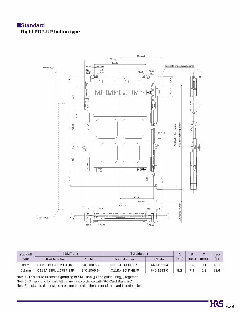
Note.1) This figure illustrates grouping of SMT unit(➀ ) and guide unit(➁ ) together.Note.2) Dimensions for card fitting are in accordance with "PC Card Standard".Note.3) Indicated dimensions are symmetrical to the center of the card insertion slot.
■ StandardRight POP-UP button type
A
Guide unit(2)
SMT Unit(1)
5
B
5
42.545
P=0.635
( 28.
05)
7.4
72
51.5
(66.25)
(35.05)
27.45
11.8
2.35
7 M
AX
10 M
AX
34.4 MAX
eject metal fittings movable range
5.9
59.5
10.1
(Pop
-up
volu
me)
84.3
(but
ton
thru
st p
ositi
on)
86.3
(but
ton
stor
ed p
ositi
on)
( 17.
55)
20.5
No.1
No.35
No.2No.36 No.34 No.68
59
NDRA
NR
PNL
AS
A
3
3
PU
SH
PU
SH
No.1
No.35
No.2
No.36 No.68
No.34
GND GND
C
Standofftype
0mm
2.2mm
640-1007-3
640-1009-9
IC11S-68PL-1.27SF-EJR
IC11SA-68PL-1.27SF-EJR
640-1251-4
640-1253-0
IC11S-BD-PNEJR
IC11SA-BD-PNEJR
3
5.2
5.6
7.8
0.1
2.3
13.1
13.6
➀ SMT unit
CL No.Part Number
➁ Guide unit A(mm)
B(mm)
C(mm)
mass(g)CL No.Part Number

A30
Note.1) This figure illustrates grouping of SMT unit(➀ ) and guide unit(➁ ) together.Note.2) Dimensions for card fitting are in accordance with "PC Card Standard".Note.3) Indicated dimensions are symmetrical to the center of the card insertion slot.
■ StandardLeft POP-UP button type
NL
2.35
59.53
NDLA
eject metal fittings movable range
PU
SH
No.1
No.35
GND
C No.2No.36
P=0.635
593
No.34
42.545
PU
SH
GNDNo.68
SMT Unuit(1)
7.4
7211
.8
5.9
20.5
7MA
X10
MA
X
84.3
(but
ton
stor
ed p
ositi
on)
86.3
(but
ton
thru
st p
ositi
on)
(28.
05)
(17.
55)
34.4MAX
No.35 No.36 No.68
Guide unit(2)
10.1
(Pop
-up
volu
me)
No.1 No.2
PNR
No.34
AS
51.5
27.45
5
A
B
5
(35.05)
(66.25)
Standofftype
0mm
2.2mm
640-1008-6
640-1010-8
IC11S-68PL-1.27SF-EJL
IC11SA-68PL-1.27SF-EJL
640-1252-7
640-1254-2
IC11S-BD-PNEJL
IC11SA-BD-PNEJL
3
5.2
5.6
7.8
0.1
2.3
13.1
13.6
➀ SMT unit
CL No.Part Number
➁ Guide unit A(mm)
B(mm)
C(mm)
mass(g)CL No.Part Number

A31
Note.1) This figure illustrates grouping of SMT unit(➀ ) and guide unit(➁ ) together.Note.2) Dimensions for card fitting are in accordance with "PC Card Standard".Note.3) Indicated dimensions are symmetrical to the center of the card insertion slot.
■ ReverseRight POP-UP button type
42.545
P=0.635
34.4 MAX
7 M
AX
10 M
AX
eject metal fittings movable range
59.5
B
5
5
A
27.45
2.35
(35.05)
(66.25)
10.1
(Pop
-up
volu
me)
84.3
(but
ton
thru
st p
ositi
on)
86.3
(but
ton
stor
ed p
ositi
on)
5.9
51.5
20.5
( 28.
05)
( 17.
55)
11.8
726
A
PNR
NURA
3
3 59
No.1No.35No.2
No.36GNDGND
No.68No.34
SMT Unit(1)
Guide unit(2)
No.1No.2
No.36 No.35No.68
No.34
C
Standofftype
0mm
2.2mm
640-1003-2
640-1005-8
IC11S-68PLR-1.27SF-EJR
IC11SA-68PLR-1.27SF-EJR
640-1255-5
640-1257-0
IC11S-BUR-PNEJR
IC11SA-BUR-PNEJR
2.7
4.9
5.6
7.8
0.1
2.3
13.3
13.7
➀ SMT unit
CL No.Part Number
➁ Guide unit A(mm)
B(mm)
C(mm)
mass(g)CL No.Part Number

A32
Note.1) This figure illustrates grouping of SMT unit(➀ ) and guide unit(➁ ) together.Note.2) Dimensions for card fitting are in accordance with "PC Card Standard".Note.3) Indicated dimensions are symmetrical to the center of the card insertion slot.
■ ReverseLeft POP-UP button type
PU
SH
PU
SH
A
NULA
Guide unit(2)
(66.25 )
7 M
AX
10 M
AX
42.545
P=0.635
34.4 MAX
eject metal fittings movable range
59.5
B
5
5
A
27.45
2.35
( 35.05 )
10.1
(Pop
-up
volu
me)
84.3
(but
ton
stor
ed p
ositi
on)
86.3
(but
ton
thru
st p
ositi
on)
5.9
51.5
20.5
( 28.
05)
( 17.
55)
11.8
726
3
3
59
No.1No.35No.2
No.36GND GNDNo.68No.34
SMT Unit(1)
No.1No.2
No.36 No.35No.68
No.34
C
PNL
Standofftype
0mm
2.2mm
640-1004-5
640-1006-0
IC11S-68PLR-1.27SF-EJL
IC11SA-68PLR-1.27SF-EJL
640-1256-8
640-1258-3
IC11S-BUR-PNEJL
IC11SA-BUR-PNEJL
2.7
4.9
5.6
7.8
0.1
2.3
13.3
13.7
➀ SMT unit
CL No.Part Number
➁ Guide unit A(mm)
B(mm)
C(mm)
mass(g)CL No.Part Number

A33
BPCB mounting pattern ● Standard Type
● Standoff 2.2mm(common to both right and left buttons)
● Without standoff(left button)
59.5±0.052
50.6MAX2
56.85MIN2
3.05MIN2MIN
2-Ø2.2 +0.1 0
Parts installation prohibited area
Shielded board-pressed area
7MIN
58.1
±0.
05
4.75±0.05
( 6.6
)
52.8±0.05
54.75±0.05
Installed cection
Card edge position
22.6
MA
X27
.6M
IN
Installed cection
0.8M
AX
( 6.6
)17
.9M
INInstalled cection
0.8M
AX
( 6.6
)
17.9
MIN
4.75±0.05 4.75±0.0554.75±0.05 54.75±0.05Card edge position Card edge position
34.5 MIN
30MAX52.8±0.0548.5MAX2
34.5 MIN
30MAX52.8±0.0548.5MAX2
0.3M
IN
0.3M
IN
0.8M
AX
0.8M
AX
1.6M
AX58
.1±
0.05
31.4
MIN
21M
IN
21M
IN31
.4M
IN
7MIN
7MIN
58.1
±0.
051.
6MAX
2MIN 2MIN
2
2
3.05MIN 3.05MIN
55.9MIN59.5±0.05
2
2
55.9MIN59.5±0.05
Shielded board-pressed area
2-Ø2.2 +0.1 0
Shielded board-pressed area
2-Ø2.2 +0.1 0
30 MIN30 MIN
Note.1) area show the pattern-inhibited area.Note.2) Indicated dimensions are symmetrical to the center
of the card insertion slot.
BPCB mounting pattern (Enlarged)● Standard type
● Without standoff(right button)

A34
BPCB mounting pattern
Note.1) area show the pattern-inhibited area.Note.2) Indicated dimensions are symmetrical to the center
of the card insertion slot.
BPCB mounting pattern (Enlarged)● Reverse type
● Reverse Type
52.8±0.05
54.75±0.05
Installed cection
59.5±0.052
50.6MAX2
56.85MIN2
3.05MIN2MIN
Parts installation prohibited area
Shielded board-pressed area
7MIN
56.7
±0.
05
4.75±0.05
( 5.2
)
Card edge position
21.2
MA
X
26.2
MIN
2-Ø2.2 +0.1 0
2MA
X
15.2
MIN
( 5.2
)
4.75±0.05 54.75±0.05
Card edge position
Shielded board-pressed area Shielded board-pressed area
Installed cection60MIN2
52.8±0.05
2MA
X
15.2
MIN
( 5.2
)
4.75±0.05 54.75±0.05
Card edge position
Installed cection60MIN2
52.8±0.05
7MIN 7M
IN
3.05MIN 3.05MIN2MIN 2MIN
2
2
50.8MAX2 54.6MIN
59.5±0.05
2
2
50.8MAX2 54.6MIN
59.5±0.05
56.7
±0.
05
56.7
±0.
05
30.2
5±0.
05
20.2
5±0.
054.
75±
0.05
14.7
5±0.
053.
925±
0.05 12
-2M
IN
12-2
MIN
18.4
5±0.
05
3.92
5±0.
054.
75±
0.05
20.2
5±0.
0518
.45±
0.05
30.2
5±0.
05
14.7
5±0.
05
2-Ø2.2
+0.1
02-Ø2.2 +0.1 0
11
● Without standoff(common to both right and left buttons)
● Standoff 2.2mm(common to both right and left buttons)
A35
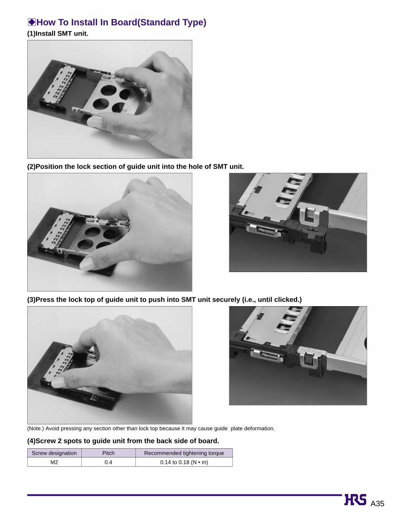
BHow To Install In Board(Standard Type)(1)Install SMT unit.
(2)Position the lock section of guide unit into the hole of SMT unit.
(3)Press the lock top of guide unit to push into SMT unit securely (i.e., until clicked.)
(4)Screw 2 spots to guide unit from the back side of board.
(Note.) Avoid pressing any section other than lock top because it may cause guide plate deformation.
M2
Screw designation
0.4
Pitch
0.14 to 0.18 (N • m)
Recommended tightening torque

A36
BHow To Install In Board(Reverse Type)(1)Install SMT unit.
(2)Position the lock section of guide unit into the hole of SMT unit.
(3)Press the lock top of guide unit to push into SMT unit securely (i.e., until clicked.)
(4)Screw 2 spots to guide unit from the back side of board.
(Note.) Avoid pressing any section other than lock top because it may cause guide plate deformation.
M2
Screw designation
0.4
Pitch
0.14 to 0.18 (N • m)
Recommended tightening torque

A37
BCautions In Installation To Boards1. After installation of SMT unit to boards, verify that the stroke arm of SMT unit
and the push rod of guide unit are located on the positions shown in fig.➀ .Also note that guide unit cannot be solder reflowed.
2. Note that the stroke arm of SMT unit and the push rod of guide unit cannot be combined when located in the position as shown in fig.➁ .
3. After SMT unit and guide unit are combined, state will be found as follows :
If located in the position shown in fig.➁ move it to the position shown in fig. ➀ by fingers.
Guide unit SMT unit
Guide unit
Guide unit
SMT unit
SMT unit
● When the push rod was extracted:● When the push rod was pressed:
Pict.➀
Pict.➁
Stroke armPush rod
intervention intervention

A38
BCaution In HandlingGuide plate is metallic, having some sharp-edged portions. Handle carefully to prevent injury to fingers.
Do not wrench the card up and down severely in the midst of insertion. This may cause damage to the connectors or cards.
Up
Down

A39
BInstallation Temperature Profile
5sec.max
240ç
200ç
160ç150ç
25ç
start 60 120
time(seconds)
250
200
board surface temperature(ç
)
150
100
50
0
(30s)(20-30s)60-90s(60s)
preheating soldering
Applicable Conditions
Reflow system : IR reflow
Solder : Paste type 63 Sn/37 Pb
(Flux content 9 wt%)
Test board Glass epoxy 60mm x 60mm x 1.6 mm
Metal mask thickness: 0.15 mm
Recommended temperature profile.
The temperature may be slightly changed according to the
solder paste type and amount.