singline catalogo farval.pdf
DESCRIPTION
Uploaded from Google DocsTRANSCRIPT

Singline® ComponentsPumps, Valves, Controllers
Bulletin SL2800Farval ®
1000 Series
M2500 Series
3000 Series
FARVAL ®
SS2200Controller
MasterDividerValveSupply LinePump
ReservoirPackage
SecondaryDivider Valves
Cycle Switch
Bearing Feed Lines
FARVAL ®Farval Lubrication Systems, Inc.
2685 Airport RoadKinston, NC 28504 U.S.A.
FARVAL ®

Singline™ series progressive system LubeSite®
LUBRICATION GROUPTable of ContentsFarval®
Introduction. . . . . . . . . . . . . . . . . . . . . . . . . . . . . . . . . . . . . . . . . . . . . . . . . . . . . . . . . . . . 1
M2500 Series Valves . . . . . . . . . . . . . . . . . . . . . . . . . . . . . . . . . . . . . . . . . . . . . . . . . . . . 2-3
1000 Series Valves. . . . . . . . . . . . . . . . . . . . . . . . . . . . . . . . . . . . . . . . . . . . . . . . . . . . . . 4-5
3000 Series Valves. . . . . . . . . . . . . . . . . . . . . . . . . . . . . . . . . . . . . . . . . . . . . . . . . . . . . . 6-7
FD Valves . . . . . . . . . . . . . . . . . . . . . . . . . . . . . . . . . . . . . . . . . . . . . . . . . . . . . . . . . . . . . . 8
Singline Valve Assembly Ordering Instructions . . . . . . . . . . . . . . . . . . . . . . . . . . . . . . . . . 9
Singline Valve Accessories. . . . . . . . . . . . . . . . . . . . . . . . . . . . . . . . . . . . . . . . . . . . . . 10-13
Manual/Mechanical Pumps . . . . . . . . . . . . . . . . . . . . . . . . . . . . . . . . . . . . . . . . . . . . . . . 14
TP Air/Hydraulic Operated Pumps . . . . . . . . . . . . . . . . . . . . . . . . . . . . . . . . . . . . . . . . . . 15
T30, 32, 33 Oil/Grease Reservoirs. . . . . . . . . . . . . . . . . . . . . . . . . . . . . . . . . . . . . . . . . . . 16
Ordering Info For Complete Air/Hydraulic Pump Packages . . . . . . . . . . . . . . . . . . . . 17-18
GPO Motor Driven Oil Pump Packages . . . . . . . . . . . . . . . . . . . . . . . . . . . . . . . . . . . . . . 19
Multiport Motor Driven Grease Pump Packages . . . . . . . . . . . . . . . . . . . . . . . . . . . . 20-23
Air & Electric Grease Drum Pumps . . . . . . . . . . . . . . . . . . . . . . . . . . . . . . . . . . . . . . . . . 24
Air/Oil . . . . . . . . . . . . . . . . . . . . . . . . . . . . . . . . . . . . . . . . . . . . . . . . . . . . . . . . . . . . . 25-27
Timers and Strainers . . . . . . . . . . . . . . . . . . . . . . . . . . . . . . . . . . . . . . . . . . . . . . . . . . . . 28
System Controls . . . . . . . . . . . . . . . . . . . . . . . . . . . . . . . . . . . . . . . . . . . . . . . . . . . . . . . . 29
Illustrations and specifications are not binding in detail.Designs are subject to modification and improvement without notice.

1
Singline™ series progressive system LubeSite®
LUBRICATION GROUPIntroductionFarval®
DESCRIPTIONThe series 1000, M2500, 3000 progressive divider valve manifold distributes and proportions incoming oil or grease to bear-ing points.
A typical divider valve manifold consists of an inlet section, three to ten valves and an end section. One assembly can serveup to a maximum of 20 lubrication points.
Individual divider valve blocks have a discharge piston and built-in outlet check valves. Blocks are offered in various outputsizes. The discharge capacity of a block is determined by varying the piston diameter in the valve block.
Twin valve blocks have two outlets located at each end of the assembly and supply rated discharge from each of the twooutlets during one complete valve cycle.
Single outlet blocks have one end outlet plugged and supply twice the rated output to the open outlet.
External crossporting of adjacent valves can be achieved with a crossport kit to combine outputs.
PROGRESSIVE DIVIDER VALVE OPERATING SEQUENCEIndividual valve blocks operate in a “progressive” sequence. During operation, the piston within the block must complete afull discharge cycle before another piston begins operation. As long as lubricant is supplied under pressure to the inlet sec-tion of the divider, manifold valve blocks will continue to operate in a progressive manner.
When lubricant flow is interrupted to the inlet block, piston movement stops. When flow resumes, piston movement com-mences at the same point in the discharge cycle. Feed lines deliver lubricant from the valve block to individual lube points.Should a discharge line become blocked, it will stop all the valves operating. Indicators are available to alert a blockage.
FIGURE 1 FIGURE 2
FIGURE 3 FIGURE 4
FIGURE #1: The inlet is connected to all pistonchambers with only one piston free to move at anyone time. With all pistons at the far right, lubeflows against the right end of piston 1.
FIGURE #2: Lube flow moves piston 1 from right toleft, displacing lube through passages to outlet 1.The shifting of piston 1 moves the lubricant flowagainst right side of piston 2.
FIGURE #3: Lube flow moves piston 2 from right toleft displacing lube through outlet 2. The shiftingof piston 2 moves the lubricant flow against rightside of piston 3.
FIGURE #4: Lube flow shifts piston 3 from right toleft displacing lube through outlet 3. The shiftingof piston 3 moves the lubricant flow against rightside of piston 1. (This would continue for as manyvalves mounted - 3-10 section)
Lube flow on left side of piston 1 begins the second cycle which shifts pistons from left to right,displacing lubricant through outlets 4, 5 and 6 ofthe valve.

2
Singline™ series progressive system LubeSite®
LUBRICATION GROUPM2500 SeriesFarval®
DESCRIPTIONThe M2500 Series valve manifolds are the principalcomponents of a Farval Single Line central lubricat-ing system. The modular construction makes the sys-tem easy to install, and can be modified and main-tained without removing any tubing. Operation ofall valves in the system can be monitored by a singlecycle indicator switch. Up to 20 bearings can be lubri-cated from one manifold assembly and up to 20 man-ifolds can be included in a system.
Zone control components can be used to build a sys-tem of any size and can be divided into individuallycontrolled and monitored zones. This permits variedcycle times, rapid trouble-shooting and easy mainte-nance.
TEN FEATURES THAT MAKE THE DIFFERENCE• VITON O-rings standard to protect against high
heat & synthetic lubricants.• Form, fit and functional interchangeable with
all major competitive brands.• Dual ported valves can be purchased as a single
outlet type (S) and converted to twin outlet (T). This reduces your inventory by 50%(see bulletin 69).
• SAE straight thread, NPSF or BSPP - all standard.• Integral or in-line solenoid valve for zone control.• Easy to assemble and replace valves without
removing tube.• Operating pressures to 3,500 psi.• .005 to .080 cubic inch discharge volumes.• Nickel plating optional. (Consult factory.)• Three to Ten section valve manifolds available.
M2500 SPECIFICATIONS• Maximum operating pressure:
3500 psi (241 BAR)• Discharge per cycle:
.005 (.08cc) to .080 (1.31cc)• Lubricants:
Oil to NLGI #2 grease• Seals:
VITON O-rings (70 durometer)• Max. temperature:
350ºF (163ºC)• Material:
Steel with zinc plating, electroless nickel platingavailable on special order.
LUBE INLET PORT
INLET SECTION
VALVE SECTION
ALTERNATEOUTLET PORT
DISCHARGEPORTS
BASE SECTION
END SECTION
TIE RODS
M2500 3 SECTION VALVE ASSEMBLY
3 section divider 6.2 lbs 2.8 kg4 section divider 7.6 lbs 3.5 kg5 section divider 9.1 lbs 4.1 kg6 section divider 10.5 lbs 4.8 kg7 section divider 11.9 lbs 5.4 kg8 section divider 13.4 lbs 6.1 kg9 section divider 14.8 lbs 6.7 kg10 section divider 16.2 lbs 7.4 kg
Approx. Net Weight (Divider Valve Assembly)

3
Singline™ series progressive system LubeSite®
LUBRICATION GROUPM2500 SeriesFarval®
M2500 DIVIDER VALVE ASSEMBLIES CONSIST OF AN INLET SECTION, BASE SECTIONS (3-10), END SECTION AND VALVES
05 .005 (.08) .010 (.16) MCVA250105T - MCVA250105S -10 .010 (.16) .020 (.33) MCVA250110T - MCVA250110S -15 .015 (.25) .030 (.49) MCVA250115T - MCVA250115S -20 .020 (.33) .040 (.66) MCVA250120T MCV250120TP MCVA250120S MCV250120SP25 .025 (.41) .050 (.82) MCVA250125T MCV250125TP MCVA250125S MCV250125SP30 .030 (.49) .060 (.98) MCVA250130T MCV250130TP MCVA250130S MCV250130SP35 .035 (.57) .070 (.1.15) MCVA250135T MCV250135TP MCVA250135S MCV250135SP40 .040 (.66) .080 (1.31) MCVA250140T MCV250140TP MCVA250140S MCV250140SP
DISCHARGE CU. IN (cc) VALVE SECTIONS
SINGLE OUTLETTWIN OUTLETTWINOUTLET
SINGLEOUTLET STANDARD W/CYCLE PIN STANDARD W/CYCLE PIN
VALVE
SIZE
NOTES:• Valve sections include O-rings and mounting screws• MCVA2501BP bypass valve with VITON O-rings is available.
PART NUMBERS TO ORDER DIVIDER BLOCK COMPONENTSINLET SECTION
InletType
StandardZone-oil*
Zone-grease*
#4 SAEMCI2504AMCI2504ZAMCI2506ZZ
1/4-18 NPSFMCI2504BMCI2504ZBMCI2506ZB
1/4-19 BSPPMCI2504CMCI2504ZCMCI2506ZC
TORQUE SPECIFICATIONS• Tie Rod Nuts 5-8 foot pounds• Outlet Port Fitting 8-9 foot pounds• Piston Enclosure Plugs 12-15 foot pounds• Valve mounting screws 8-9 foot pounds
VALVE BASE SECTIONSIncludes integral check valves, VITON O-ringsMCBA2502A: #4 SAE discharge portsMCBA2502B: 1/8-27 NPSF discharge portsMCBA2502C: 1/8-28 BSPP discharge ports
END SECTIONMCEA2503 Includes VITON O-rings
3 MCRK250534 MCRK250545 MCRK250556 MCRK250567 MCRK250578 MCRK250589 MCRK2505910 MCRK250510
Number ofSections
Tie RodKit Number
TIE ROD KITIncludes 3 tie rods and locknuts.
3 3.58 91 4.52 1154 4.50 114 5.44 1385 5.42 138 6.36 1626 6.34 161 7.28 1857 7.27 185 8.20 2088 8.19 208 9.13 2329 9.11 231 10.04 25510 10.03 255 10.97 279
No. ofSections inch
A
mm inch mm
Inlet port1/4-18 NPSF1/4-19 BSPP#4 SAE
AlternateOutlet Port
1/8-27 NPTF
B
A
Discharge Ports1/8-27 NPTF1/8-28 BSPP#4 SAE
B
* Select Applicable Control Valve (MCZ2501 or MCZ2503) from page 13

4
Singline™ series progressive system LubeSite®
LUBRICATION GROUP1000 SeriesFarval®
DESCRIPTIONThe Series 1000 progressive divider valve manifolddistributes and proportions incoming oil or grease tobearing points.
A typical divider valve manifold consists of an inletsection, three to nine valves and an end section. Oneassembly can serve up to a maximum of 18 lubrica-tion points.
Individual divider valve blocks have a discharge pis-ton and built-in outlet check valves. Blocks areoffered in three output sizes. The discharge capacityof a block is determined by varying the piston diam-eter in the valve block.
Twin valve blocks have two outlets located at eachend of the assembly and supply rated discharge fromeach of the two outlets during one complete valvecycle.
Single outlet blocks have one end outlet plugged andsupply twice the rated output to the open outlet.
External crossporting of adjacent valves can beachieved with a crossporting kit to combine outputs.
PROGRESSIVE DIVIDER VALVE OPERATINGSEQUENCEIndividual valve blocks operate in a “progressive”sequence. During operation, the piston within theblock must complete a full discharge cycle beforeanother piston begins operation. As long as lubricantis supplied under pressure to the inlet section of thedivider, manifold valve blocks will continue to oper-ate in a progressive manner.
When lubricant flow is interrupted to the inlet block,piston movement stops. When flow resumes, pistonmovement commences at the same point in the dis-charge cycle. Feed lines deliver lubricant from thevalve block to individual lube points. Should a dis-charge line become blocked, it will stop all the valvesoperating.
Indicators are available to alert a blockage.
1000 SERIES SPECIFICATIONS
• Material
Steel (zinc plated)
• Maximum operating pressure:
2000 psi (138 BAR)
• Discharge per cycle
.005 (.082cc) - .030 (.492cc)
• Lubricants
Oil to NLGI #2 grease
• Seals:
Non-asbestos composition with steel core
• Max. temperature:
350ºF (163ºC)
3 section divider 1 lb., 15 oz. (0.88 kg)4 section divider 2 lbs., 5 oz. (1.04 kg)5 section divider 2 lbs., 11 oz. (1.21 kg)6 section divider 3 lbs., 1 oz. (1.38 kg)7 section divider 3 lbs., 7 oz. (1.55 kg)8 section divider 3 lbs. 13 oz. (1.72 kg)9 section divider 4 lbs., 3 oz. (1.89 kg)
Approx. Net Weight (Divider Valve Assembly)
INLETSECTION
CROSSPORT KIT
1/8” NPTOR 1/8” BSPALTERNATE
OUTLETPORTS
VALVESECTIONS
ENDSECTION
1/8” NPTOR 1/8” BSPLUBE INLET
1/8” NPTOR 1/8” BSP
LUBE OUTLET
PISTONENCLOSURE
PLUGS
.190 MTGHOLES (4)

5
Singline™ series progressive system LubeSite®
LUBRICATION GROUP1000 SeriesFarval®
VALVEBLOCK
SECTION
1000 DIVIDER VALVE ASSEMBLIES CONSIST OF AN INLET SECTION, SEVERAL VALVE SECTIONS (3-9) AND AN END SECTION
05 .005 (.082) .010 (.164) 1000-05AT N/A N/A 1000-05AS N/A N/A10 .010 (.164) .020 (.328) 1000-10AT N/A N/A 1000-10AS N/A N/A15 .015 (.246) .030 (.492) 1000-15AT 1000-157LT 1000-158LT 1000-15AS 1000157LS 1000-158LS
DISCHARGE CU. IN (cc) VALVE SECTIONS
SINGLE OUTLETTWIN OUTLETTWINOUTLET
SINGLEOUTLET STANDARD W/CYCLE PIN W/CYCLE PIN SW STANDARD W/CYCLE PIN W/CYCLE PIN SW
VALVE
SIZE
NOTES:• Above are supplied with 1/8” NPT threads, if 1/8” BSP threads are required add BSP after above part numbers.
Example: 1000-05ATBSP• Above cycle pin and cycle switch numbers are for left side mounted pin/switch, if right side mounted pin or switch is
required substitute R for L in part #. Example: 1000-157RT.
PART NUMBERS TO ORDER DIVIDER BLOCK COMPONENTS TORQUE SPECIFICATIONS• Tie Rod Nuts 60-70 inches• Outlet Port Fitting 72-89 inch pounds• Piston Enclosure Plugs 15 foot pounds
DESCRIPTION PART NO.Inlet Section 1/8” NPT 1006-1Inlet Section 1/8” BSP 1006-1BSPEnd Block 1007-1Gaskets (Order Separate) 1009
Number ofValve Blocks
TIE ROD KITS*
Tie Rod Kit, 3 Valves 1017-3KTie Rod Kit, 4 Valves 1017-4KTie Rod Kit, 5 Valves 1017-5KTie Rod Kit, 6 Valves 1017-6KTie Rod Kit, 7 Valves 1017-7KTie Rod Kit, 8 Valves 1017-8KTie Rod Kit, 9 Valves 1017-9K
*(Kit includes 2 tie rods and 2 nuts)
3456789
2.34 (59.4)2.92 (74.2)3.50 (89.0)4.08 (103.7)4.66 (118.5)5.25 (133.3)5.83 (148.1)
B Dimension (MM)
2.87 (73.1)3.46 (87.9)4.04 (102.6)4.62 (117.4)5.20 (132.2)5.78 (147.0)6.37 (161.8)
VALVE MANIFOLDS ASSEMBLIES
1.06
3.23
.75
1/8 NPSF OR 1/8 BSPLUBE OUTLET
CYCLE INDICATOR
1/8 NPSF INDICATOR OUTLET
07/32 (4) MOUNTING HOLES
INLET SECTION
.75 .69
.33
1.09
1.38
A B
.55 TYP
ENDSECTION
.1.28
2.13
2.54
.25
1/8 NPSF OR 1/8 BSPLUBE OUTLETS
Dimensions in inches
A Dimension (MM)
6
Singline™ series progressive system LubeSite®
LUBRICATION GROUP3000 SeriesFarval®
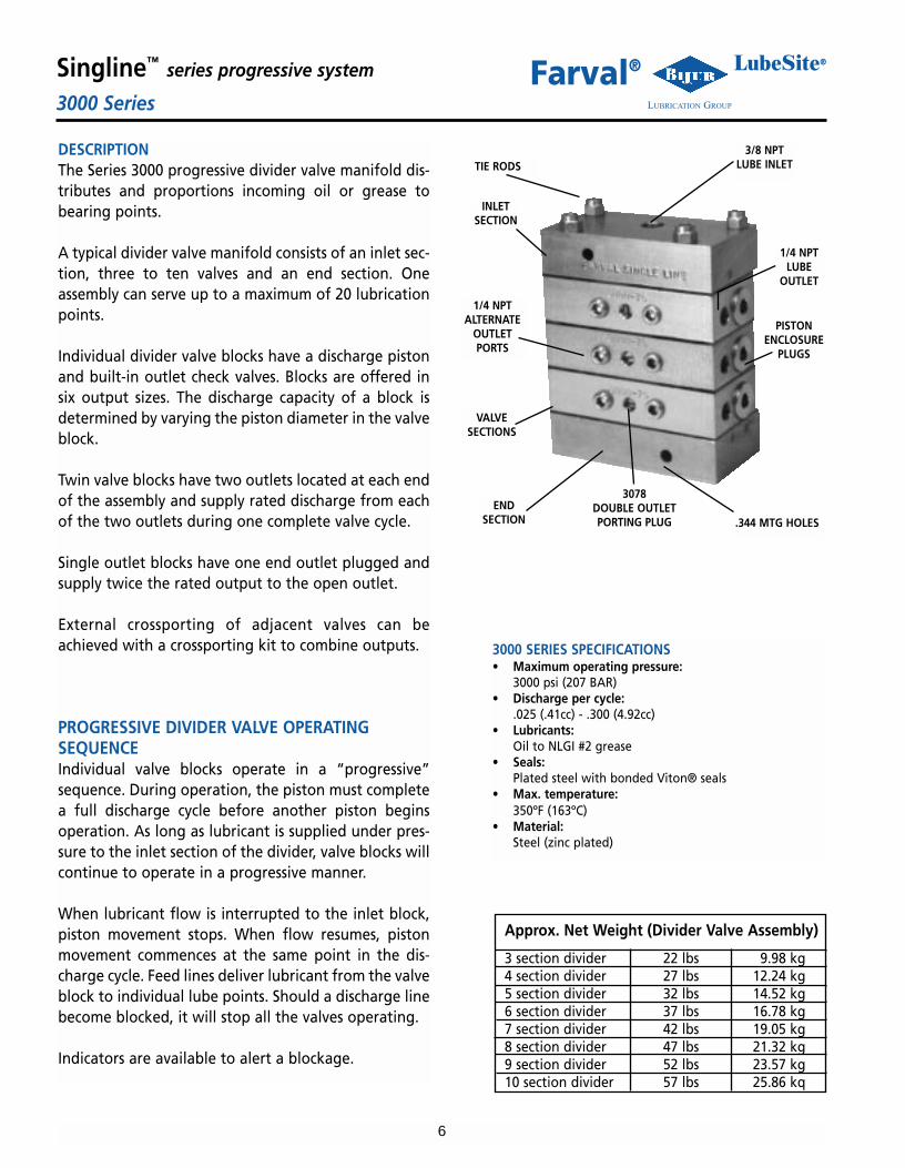
DESCRIPTIONThe Series 3000 progressive divider valve manifold dis-tributes and proportions incoming oil or grease tobearing points.
A typical divider valve manifold consists of an inlet sec-tion, three to ten valves and an end section. Oneassembly can serve up to a maximum of 20 lubricationpoints.
Individual divider valve blocks have a discharge pistonand built-in outlet check valves. Blocks are offered insix output sizes. The discharge capacity of a block isdetermined by varying the piston diameter in the valveblock.
Twin valve blocks have two outlets located at each endof the assembly and supply rated discharge from eachof the two outlets during one complete valve cycle.
Single outlet blocks have one end outlet plugged andsupply twice the rated output to the open outlet.
External crossporting of adjacent valves can beachieved with a crossporting kit to combine outputs.
PROGRESSIVE DIVIDER VALVE OPERATINGSEQUENCEIndividual valve blocks operate in a “progressive”sequence. During operation, the piston must completea full discharge cycle before another piston beginsoperation. As long as lubricant is supplied under pres-sure to the inlet section of the divider, valve blocks willcontinue to operate in a progressive manner.
When lubricant flow is interrupted to the inlet block,piston movement stops. When flow resumes, pistonmovement commences at the same point in the dis-charge cycle. Feed lines deliver lubricant from the valveblock to individual lube points. Should a discharge linebecome blocked, it will stop all the valves operating.
Indicators are available to alert a blockage.
3000 SERIES SPECIFICATIONS• Maximum operating pressure:
3000 psi (207 BAR)• Discharge per cycle:
.025 (.41cc) - .300 (4.92cc)• Lubricants:
Oil to NLGI #2 grease• Seals:
Plated steel with bonded Viton® seals• Max. temperature:
350ºF (163ºC)• Material:
Steel (zinc plated)
TIE RODS
INLETSECTION
1/4 NPTALTERNATE
OUTLETPORTS
VALVESECTIONS
ENDSECTION
3 section divider 22 lbs 9.98 kg4 section divider 27 lbs 12.24 kg5 section divider 32 lbs 14.52 kg6 section divider 37 lbs 16.78 kg7 section divider 42 lbs 19.05 kg8 section divider 47 lbs 21.32 kg9 section divider 52 lbs 23.57 kg10 section divider 57 lbs 25.86 kq
Approx. Net Weight (Divider Valve Assembly)
3/8 NPTLUBE INLET
1/4 NPTLUBE
OUTLET
PISTONENCLOSURE
PLUGS
.344 MTG HOLES
3078DOUBLE OUTLETPORTING PLUG

7
Singline™ series progressive system LubeSite®
LUBRICATION GROUP3000 SeriesFarval®
3000 DIVIDER VALVE ASSEMBLIES CONSIST OF AN INLET SECTION, SEVERAL VALVE SECTIONS (3-10) AND AN END SECTION
25 .025 (.41) .050 (.82) 300025 N/A N/A 300025X N/A N/A50 .050 (.82) .100 (1.64) 300050 3000507 3000508 300050X 3000507X 3000508X75 .075 (1.23) .150 (2.46) 300075 3000757 3000758 300075X 3000757X 3000758X100 .100 (1.64) .200 (3.28) 3000100 30001007 30001008 3000100X 30001007X 30001008X125 .125 (2.05) .250 (4.10) 3000125 30001257 30001258 3000125X 30001257X 30001258X150 .150 (2.46) .300 (4.92) 3000150 30001507 30001508 3000150X 30001507X 30001508X
DISCHARGE CU. IN (cc) VALVE SECTIONS
SINGLE OUTLETTWIN OUTLETTWINOUTLET
SINGLEOUTLET STANDARD W/CYCLE PIN W/CYCLE SW STANDARD W/CYCLE PIN W/CYCLE SW
VALVE
SIZE
INLET SECTION: 3006END SECTION: 3007
TORQUE SPECIFICATIONS• Tie Rod Nuts 240 inch pounds• Outlet Port Fitting 72-96 inch pounds• Piston Enclosure Plugs 48 foot pounds
Number ofValves
345678910
DimensionA
5-7/166-3/48-1/169-7/1610-3/412-1/1613-3/8
14-11/16
DimensionB
6-9/167-7/89-3/1610-9/1611-7/813-3/1614-1/2
15-13/16
3/8” PIPE TAP(INLET BLOCK ONLY)
ALTERNATE DISCHARGE PORTS1/4” NPSF
TIE ROD - SEECHART - 4 REQ’D
FT-2509-1 SPACER
DISCHARGE PORTS 1/4” NPSF
(2) 11/32” DIA.MOUNTING HOLES
USE U-225B15MOUNTING SCREWS
3/8”-24 THREAD
3/8”
*Sold individually each assembly requires 4 tie rods
INLET (3006) AND END (3007)BLOCK DIMENSIONS
3000 VALVE MANIFOLD DIMENSIONS
3 FT25171A4 FT25171B5 FT25171C6 FT25171D7 FT25171E8 FT25171F9 FT25171G10 FT25171H
No. Valvesin Manifold
Tie Rod*Part Number
GASKET (FT-2509-1) DIMENSIONS(Order Separate)
MANIFOLD TIE ROD FT-2517
PLATED STEEL WITHBONDED VITON® SEALS
NOTE:Specify one locknut U-251C with each tie rod.
2-3/4”
1-9/16”
2-5/8”
5-1/4” .075”
2-1/2”
5-1/4”

8
Singline™ series progressive system LubeSite®
LUBRICATION GROUPFD SeriesFarval®
DESCRIPTIONFARVAL FD valves are designed for use with seriesprogressive oil and grease lubrication systems. TheFD-2 is designed to discharge lube to two points,each receiving .040 cubic inches per cycle.
The FD-3 feeder is designed to discharge lube tothree points. Two receive .020 cubic inches percycle and one point receives .040 cubic inches percycle.
The FD-4 feeder is designed to discharge lube tofour points. Each point receives .020 cubic inchesper cycle.
The FD-6 feeder is designed to discharge lube to sixpoints. Each point receives .010 cubic inches percycle.
HOW TO ORDER
StandardModel
With CycleIndicator Pin(Right Side)
Number ofLube Outlets
FD-2
FD-3
FD-4
FD-6
FDP-2
FDP-3
FDP-4
2
3
4
6
SPECIFICATIONS• Maximum operating pressure:
3000 psi (207 BAR)• Lubricant:
Oil to NLGI #2 grease• Seals
Viton O-Rings• Material:
Steel (zinc plated)• Max. Temperature:
350ºF (163ºC)• Net Weight:
1 lb. 8 oz. (0.68 kg)• Volume: (Lubricant required to cycle divider valve once)
FD-2, FD-3, & FD-4 0.080 in.3 (1.31 ccm)FD-6 0.060 in. 3 (0.98 ccm)
• Torque RatingsAssembly Bolts 8-9 ft. lbs.Piston Enclosure Plugs 12-15 ft. lbs.Indicator Plug 12-15 ft. lbs.
Note: To use High Pressure indicators with FDDivider Valves, a tee (Part No.’s U101A1 Nippleand U137A Tee) is required for each outlet.(See page 10 for indicators)
CYCLE SWITCH AND BRACKET ARE AVAILABLECycle Switch No. - 17324Bracket Assembly No. - 33583
3.00”(76.2)
1.21”(31)
1.75”(44.4)

9
Singline™ series progressive system LubeSite®
LUBRICATION GROUPOrdering InstructionsFarval®
Completely assembled Farval Single Line M2500 Modularvalve manifolds can be ordered as follows:
First, select the manifold base assembly from the table.This assembly includes the inlet section, valve base sec-tions, end section, tie rods, nuts and o-rings; the valvesections are installed on it. Each valve section and bypasssection requires a base section, and every manifold musthave at least 3 operating valve sections.
Next, specify the valves, bypass sections and accessories.Begin at the first section after the inlet and continuetowards the end section. Separate each entry with aslash:
/_ _ _, _ _ _, _ _ _1 2 3 4
INLETTYPE
DISCHARGE PORTS
#4SAE
M2500A3M2500A4M2500A5M2500A6M2500A7M2500A8M2500A9M2500A10M2500A3ZM2500A4ZM2500A5ZM2500A6ZM2500A7ZM2500A8ZM2500A9ZM2500A10ZM2500A3XM2500A4XM2500SA5XM2500A6XM2500A7XM2500A8ZM2500A9XM2500A10X
345678910345678910345678910
M2500B3M2500B4M2500B5M2500B6M2500B7M2500B8M2500B9M2500B10M2500B3ZM2500B4ZM2500B5ZM2500B6ZM2500B7ZM2500B8ZM2500B9ZM2500B10ZM2500B3XM2500B4XM2500B5XM2500B6XM2500B7XM2500B8XM2500B9XM2500B10X
M2500C3M2500C4M2500C5M2500C6M2500C7M2500C8M2500C9M2500C10M2500C3ZM2500C4ZM2500C5ZM2500C6ZM2500C7ZM2500C8ZM2500C9ZM2500C10ZM2500C3XM2500C4XM2500C5XM2500C6XM2500C7XM2500C8XM2500C9XM2500C10X
1/8-27 NPSF 1/8-28 BSPP
NUMBER OFSECTIONS
STANDARD
ZONE-OILMCZ2501
SERIES
ZONE-GREASE
MCZ2503SERIES
Inlet Section
Outlet
OutletOutlet
Outlet
End section
Crossport bar
1 -Valve/size (05, 10, 15, etc.)2 -Outlets
• T - Twin • SL - single outlet to left• S - single; no outlet • SR - single; outlet to right
3 -Optional accessories• PP - pin -type pressure indicator** • CS - cycle switch*• CIP - cycle indictor PIN • CP - crossport
*Specify which cycle switch model (See page13)**Provide part number (See page10)Add L or R to the above codes to specify the location of eachaccessory
4 -Other accessories (as required)
NOTE: Zone control valves are ordered as separate items asshown on pages 12 and 13. Omit the mounting style code.Other accessories such as electrical cables must also be orderedas separate items.
EXAMPLE: Ordering code for complete assembly.The complete part number for an M2500 manifold with the fol-lowing specifications would be:M2500B5/05SR/10S,CPR/10SL/BP/30T
5 section manifold, NPSF ports, standard inlet = M2500B5
05 single, outlet right, visual indicator to left =05SR
10 single, no outlet, crossport to right =10S,CPR
10 single, outlet left =10SL
Bypass section =BP
30 twin, outlets left and right =30T
NOTE: For 1000/3000 series, replace M2500B inthe above example with 1001/3001. Must haveminimum of 3 working sections.
Provide basic sketch similar to above when ordering
Note: Unused outletports are plugged

10
Singline™ series progressive system LubeSite®
LUBRICATION GROUPSingline AccessoriesFarval®
CROSSPORT KITCrossport kit is installed in the alternate outlet port of adjacentvalves to combine the outputs to feed a single lubrication point.
1000 SeriesModel No. 32265-1 (BSP)Model No. 32265-2 (NPT)
M2500 SeriesModel No. MCCA2501
3000 SeriesModel No. 32763
.82”
HIGH PRESSURE INDICATORSThese indicators are spring-loaded and can only bereset when system pressure decreases. The indicator’smemory pin remains extended until manually reset.They are installed in the alternate outlet port.
2035A-5 500 psi2035A-10 1000 psi2035A-15 1500 psi2035A-20 2000 psi2035A-30 3000 psi
PartNumber
PressureRating
NON-RELIEVING TYPEFOR 1000/M2500 SERIES
2135-5 500 psi2135-10 1000 psi2135-15 1500 psi2135-20 2000 psi
PartNumber
PressureRating
*RELIEVING TYPEFOR 1000/M2500 SERIES
*These have small weep holeto relieve pressure
FT25353G 600FT25353Y 1000FT25353R 2000
PartNumber
PressureRating
NON-RELIEVING TYPEFOR 3000 SERIES
RUPTURE DISC INDICATORSThese indicators burst at a selected pressure to automatically relieve exces-sive system pressure. They are installed in an alternate outlet port. Allindicators are assembled with one rupture disc.
1041-2YW 1450 psi Yellow FT15423YWK1041-2RD 1750 psi Red FT15423RDK1041-2PR 3250 psi Purple FT15423PRK1041-2YN 3700 psi Yellow/Neutral FT15423YNK
PartNumber
BurstPressure
FOR 1000/M2500 SERIES
DiscColor
ReplacementDisc Kit*
FT25413B 900 Black FT15421BKFT25413Y 1450 Yellow FT15421Y
FT25413RD 1900 Red FT15421RD
PartNumber
BurstPressure
FOR 3000 SERIES
DiscColor
ReplacementDisc
*discs are sold in packs of 10 piecesAbove sold with 10 extra discs
1/4” NPTFOR 3000 SERIES
1/8” NPT FOR1000/M2500
SERIES
1.05
1.25
1/4” NPTFOR 3000 SERIES
1/8” NPT FOR1000/M2500
SERIES
1.3” for 32763

11
Singline™ series progressive system LubeSite®
LUBRICATION GROUPSingline AccessoriesFarval®
FARVAL ZONE CONTROL VALVESZone Control Valves are typically used to isolate certain sections on amachine to receive more/less frequent lube cycles. Farval offers a fullrange of zone control valves to satisfy a variety of requirements.
STYLE:• MCZ2501F series for oil systems operating up to 1500 psi• MCZ2501A series for oil systems operating between 1500 and 3000 psi• MCZ2503B series for all grease systems operating up to 3000 psi
INSTALLATION:• In the inlet section of M2500 series manifold (see page 3 for zone inlets)• As a stand alone component mounted in a remote location
ELECTRICAL• 115 volts AC (50 or 60 hz)• 24 volts DC• Class H coils
CONNECTORS• Standard 1/2 inch conduit with insulated 18 AWG leads• Automotive 3 pin connector accepts Brad harrison Mini-Change or
Crouse Hinds Mini-Line connectors. Conforms to ANSI B93.55M• Hirschmann connector
PORT TYPES• Integral valves: #4 SAE, 1/4-18 NPSF or 1/4-19 BSPP on inlet• Remote valves: #6 SAE or 1/4-18 NPTF on inlet and outlet
Grease Service (MCZ2503 Series) Oil Service (MCZ2501 Series)
M2500 IntegralOil or Grease
Remote-GreaseMCZ2503B
HirschmanConnector
Inrush Current .21 amp .21 amp .17 ampPower 20 watts 20 watts 20 wattsLead Length 24 in. 24 in. 18 in.
Series MCZ2501F
ELECTRICAL SPECIFICATIONS
MCZ2501A MCZ2503B
M2500 VALVE MANIFOLDS WITH INTEGRAL ZONE CONTROL
3 3.58 91 7.03 1794 4.50 114 7.95 2025 5.42 138 8.97 2286 6.34 161 9.80 2497 7.27 185 10.72 2728 8.19 208 11.64 2969 9.11 231 12.56 31910 10.03 255 13.48 342
No.ofSections
M L
Inch Inch MMMM
Inlet Port1/4-18 NPST; 1/4-19 BSPT
#4 SAE
AlternateOutlet Port1/8-27 NPTF
Q
Discharge Ports1/8-27 NPSF1/8-28 BSPP
#4 SAE
DischargePort
1/4-18NPTF#6 SAE
InletPort
1/4-18NPTF#6 SAEInlet Port
1/4-18NPTF#6 SAE
1.00 1.50
2.00
.28 dia
1.25
3.32
1.00
1.50
1.893.25
2.00
Lubricant
Oil Service(MCZ2501 Series)
Grease Service(MCZ2503 Series)
P
1.50 1.82
2.25 2.35
Q
2.50
.281.25
2.52
5.60
Discharge Port1/4-18NPTF
#6 SAE
Remote-Oil
REMOTE ZONE CONTROL VALVESELECTRICALCONNECTOR ELECTRICAL
CONNECTOR

12
Singline™ series progressive system LubeSite®
LUBRICATION GROUPSingline AccessoriesFarval®
ZONE CONTROL VALVE SELECTION CHART
For oil systems below 1500 psi: *MCZ2501FFor oil systems above 1500 psi: *MCZ2501AFor all grease systems: *MCZ2503B*Note: Above are normally closed. If required, normally open can be supplied. Contact factory.
1. - Seal material: 2 - Electrical connector: 3. - Voltage: 4 - Mounting and port style:00-nitrile DL-conduit 11-115 VAC 50/60 hz (use this code for remote valves only,V0-viton HC-Hirschmann 24-24 VDC not for integral valves.)
BH-Automotive N - 1/4-18 NPTF inlet and dischargeS - #6 SAE (3/8 OD tube) inlet and discharge
EXAMPLES:• For an integral zone control in a 400 psi oil system, nitrile seals, an automotive connector, operating on 120 volt 60hz current, and with
SAE ports, order MCZ2501F00BH11 cartridge and MCI2504ZA zone inlet oil. (See page 3.)• For a remote zone control in a grease system, nitrile seals, a Hirschmann connector, 24 volt DC current, and with NPTF ports,
order MCZ2503B00HC24N.
CROUSE HINDS/BRAD HARRISON AUTOMOTIVE-TYPEELECTRICAL CONNECTORS WITH MOLDED CABLEThese feature molded 3 pin automotive connectors andare used with Farval cycle switches and Farval type BHzone control valves. The 3-conductor cables are yellowPVC insulated STO rated at 10 amps and 300 volts. Theplugs have NEMA 6P, IP68 protection.
MCC2505A - 6 feetMCC2505B - 12 feet
Available with indicator lamps for 115 volt systems. Tobe used with customer P.L.C. or DCS controllers only.
MCC2506A - 6 feetMCC2506B - 12 feet
HIRSCHMAN-TYPE ELECTRICAL CONNECTORSThese connectors, made to DIN 43650 specifications, areused with Farval type HC zone control valves. Theyinclude all hardware including gaskets. They are rated at250 VAC and 16 amperes.
MCC2509A: For Farval MCZ2501 series control valves.DIN 43650 Form B 11 mm blades. 1.12” by .82”.
MCC2510A: For Farval MCZ2503 series zone controlvalves. DIN 43650 Form A. 1.08” square.
MCC2505
MCC2509A
MCC2510A
1 2 3 4
ELECTRICAL ACCESSORIES FOR ZONE CONTROL VALVES AND CYCLE SWITCHES
13
Singline™ series progressive system LubeSite®
LUBRICATION GROUPSingline AccessoriesFarval®
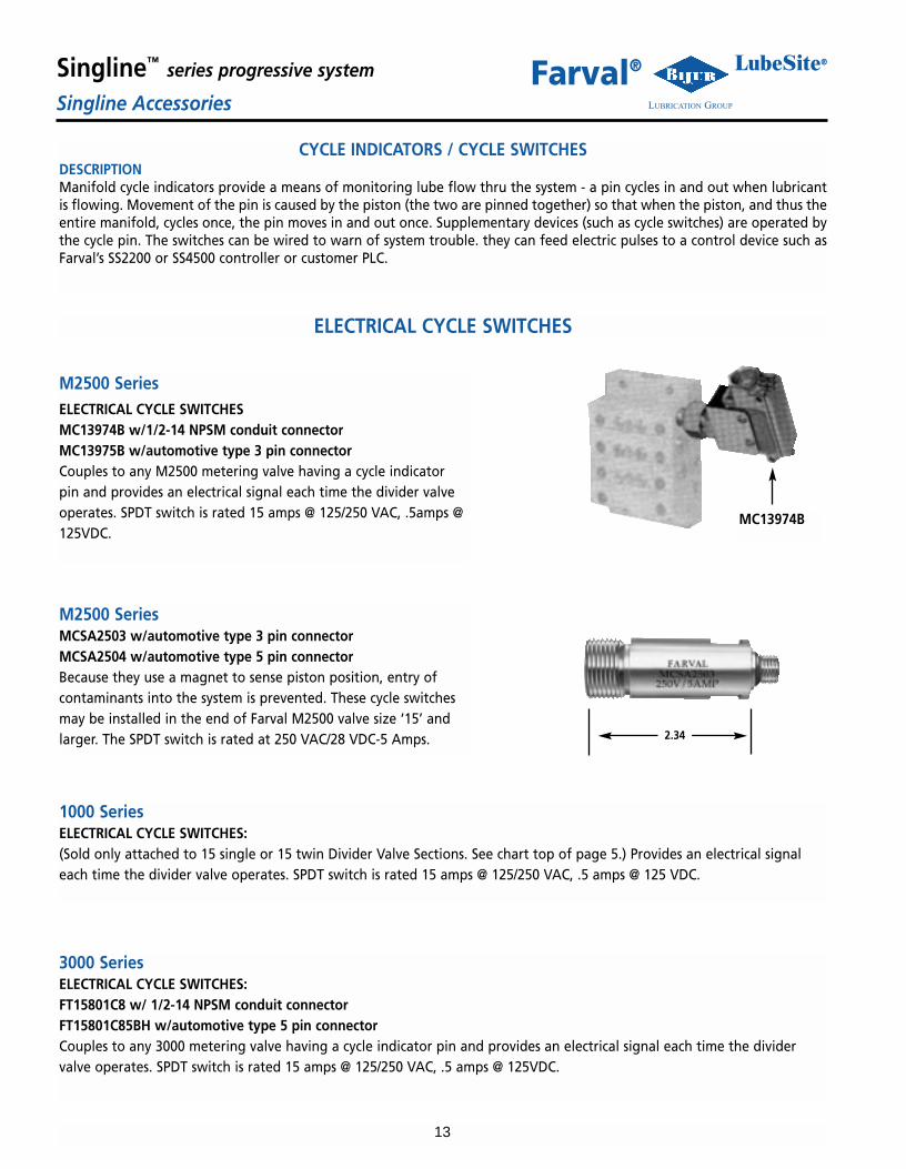
CYCLE INDICATORS / CYCLE SWITCHESDESCRIPTIONManifold cycle indicators provide a means of monitoring lube flow thru the system - a pin cycles in and out when lubricantis flowing. Movement of the pin is caused by the piston (the two are pinned together) so that when the piston, and thus theentire manifold, cycles once, the pin moves in and out once. Supplementary devices (such as cycle switches) are operated bythe cycle pin. The switches can be wired to warn of system trouble. they can feed electric pulses to a control device such asFarval’s SS2200 or SS4500 controller or customer PLC.
ELECTRICAL CYCLE SWITCHES
M2500 SeriesELECTRICAL CYCLE SWITCHESMC13974B w/1/2-14 NPSM conduit connectorMC13975B w/automotive type 3 pin connectorCouples to any M2500 metering valve having a cycle indicatorpin and provides an electrical signal each time the divider valveoperates. SPDT switch is rated 15 amps @ 125/250 VAC, .5amps @125VDC.
MC13974B
M2500 SeriesMCSA2503 w/automotive type 3 pin connectorMCSA2504 w/automotive type 5 pin connectorBecause they use a magnet to sense piston position, entry ofcontaminants into the system is prevented. These cycle switchesmay be installed in the end of Farval M2500 valve size ‘15’ andlarger. The SPDT switch is rated at 250 VAC/28 VDC-5 Amps. 2.34
1000 SeriesELECTRICAL CYCLE SWITCHES:(Sold only attached to 15 single or 15 twin Divider Valve Sections. See chart top of page 5.) Provides an electrical signaleach time the divider valve operates. SPDT switch is rated 15 amps @ 125/250 VAC, .5 amps @ 125 VDC.
3000 SeriesELECTRICAL CYCLE SWITCHES:FT15801C8 w/ 1/2-14 NPSM conduit connectorFT15801C85BH w/automotive type 5 pin connectorCouples to any 3000 metering valve having a cycle indicator pin and provides an electrical signal each time the dividervalve operates. SPDT switch is rated 15 amps @ 125/250 VAC, .5 amps @ 125VDC.

14
Singline™ series progressive system LubeSite®
LUBRICATION GROUPMiscellaneous PumpsFarval®
Mechanical pumps are driven through a connecting rod or cam by the machine being lubricated. A small quantity of lubricant (it can beeither grease or oil) is delivered during each cycle as long as the machine is operating. Lube source can be either a reservoir or header linewith a shut off valve, filter or strainer and pressure regulator between the header line and pump. 10 psi pressure at the pump is requiredfor positive priming.
ORDERING INFORMATIONThe components - pumps, reservoir, and pressure regulator - must be ordered separately. They are not sold as complete stations. Warning: For safety of equipment and personnel, include one of the pressure indicators described. They provide relief for the system incase of line blockage.
DIRECT DRIVE PUMPS - MODEL TP21/8”NPTPORT FOR
INSTALLINGPRESSUREINDICATOR
FROMLUBRICANTRESERVOIR
CAM
CAM OPERATED PUMP
TO SYSTEM
PUMP SPECIFICATIONS
TP2C2 0 .095 (1.6cc) Cam Spring 60 30 75 3711 Times Operating Force As required
PUMPPARTNO.
DISCHARGEPER STROKE
CU. IN.
METHOD OFPUMP
OPERATION
PUMPRETURNACTION
MINIMUM MAXIMUM
MAXIMUM CYCLES PER MIN.MAXIMUM
OPERATINGPRESSURE
AT MAX. DISCH.ADJUSTMENT
AT 50% MAX. DISCH.ADJUSTMENT
PRESSURE RATIO@ SUGGESTED
MINIMUM OPERATINGPRESSURE NLGI #1 NLGI #1NLGI #2 NLGI #2
Cam operated pumps can also be mounted on a way or slide andoperated by a trip cam.
MANUAL PUMPING STATIONSFor bearings that require an application of lubricant infre-quently, the manually-operated pumping unit is used, andmay be located on the machine or at any convenient pointnearby.
These units consist of a double-acting piston pump, recipro-cated by a hand lever through a rack-and-gear segment. Aquick-fill connection provides a convenient means of fillingthe reservoir, and an inlet filter screen gives added protectionagainst the entry of dirt.
Where oil is employed, a float with oil level rod replaces thegrease follower plate. Three sizes of reservoirs provide a sup-ply of lubricant adequate for the number of bearings beinglubricated.
DA4-120A DA5-120A DA6-120A DA4-120B DA6-120B
VISUAL INDICATORLEVEL (OIL & GREASE)
DA4-120A or DA4-102ADA4-120B or DA4-102BDA5-120ADA6-120ADA6-120B
GreaseOil
GreaseGrease
Oil
4-1/2 lbs.2-1/2 qts.8-1/4 lbs.12-1/2 lbs.6-1/2 qts.
24.022.037.050.938.9
.45 cubic inches(7.44cc)
Part NumberTypeLube
ReservoirCapacity
A(Max.)
DischargePer Cycle*
*This is the volume discharged by one in and outoperation of the hand lever.
Note
Series 120 pump is designed for single line lubricatingsystems and series 102 for jacking heavy loads.
A

15
Singline™ series progressive system LubeSite®
LUBRICATION GROUPPumps - Models TP11, 12, 13, 22, 23Farval®
APPLICATIONTP pumps are used on central pumping stations with T30, T32 or T33 reservoirs; or in bulk oil installations without reservoirs.They are actuated by air or hydraulic power.
DESCRIPTIONThe pumps meet a wide range of requirements as shown in the table below. The discharge capacities range from .015 to .170cubic inches per stroke. These pumps offer a range of pressure ratios, and are available as single acting, spring return or dou-ble acting, power return.
POWER SUPPLY INLET PORT FORALL TP PUMPS, ALSO EXHAUSTFOR SINGLE ACTING PUMPS
MODELS TP13 AND TP23 HAVE 2-1/2”DIA. ROUND OPERATING CYLINDERAS SHOWN. ALL OTHERS HAVE 2”HEX. OPERATING CYLINDER
POWER INLET PORT FORDOUBLE ACTING SERIES 2 PUMPS.PLUG WITH VENTED PLUG FORSERIES 1 PUMPS LUBE DISCHARGE PORT
1⁄4 NPT
1/8” NPT PORTFOR INSTALLINGPRESSUREINDICATOR /GAUGE
LUBE OUTPUTADJUSTING’SCREW -REMOVE RETAINERSCREW TO MAKEADJUSTMENT
HOLES FOR OBSERVINGSETTING OF LUBE OUTPUTADJUSTING SCREW
AIR BLEEDER VALVE
3/8 NPT LUBE INLET PORTFROM RESERVOIR
PUMP SPECIFICATIONS
ORDERCODELTR.
A
B
C
E
J
K
L
TP111
TP112
TP121
TP131
TP222
TP231
TP232
.015 (.25)
.015 (.25)
.015 (.25)
.035 (.57)
.035 (.57)
.035 (.57)
.035 (.57)
.068 (1.1)
.068 (1.1)
.068 (1.1)
.068 (1.1)
.170 (2.8)
.170 (2.8)
.170 (2.8)
Hydraulic
Hydraulic
Air
Air
Air or Hydraulic
Air
Air
Spring
Hydraulic
Spring
Spring
Air or Hydraulic
Spring
Air
6:1
6:1
18:1
50:1
7:1
18:1
20:1
250 psi
100 psi
60 psi
30 psi
200 psi
60 psi
50 psi
2000 psi
2000 psi
200 psi
50 psi
500 psi
200 psi
200 psi
40 20 50 25
PUMPPARTNO.
DISCHARGECU. IN. PER
STROKE (C.C.)
TYPE(1)
METHOD OFPUMP PISTON
RETURNMINIMUMMINIMUM MAXIMUM MAXIMUM
MAXIMUM CYCLES PER MIN.AIR OR HYDRAULICINPUT PRESSURE
(3)AT MAX. DISCH.ADJUSTMENT
AT 50% MAX. DISCH.ADJUSTMENT
PUMPPRES-SURERATIO
(2) NLGI #1 NLGI #1NLGI #2 NLGI #2
(1) All pumps except TP13 and TP23 models may be used with either air or hydraulic supply power. Listings in this column showour recommendations based on pump pressure ratios in relation to typical machine air and hydraulic power supply pressures.Hydraulic pressure must fall below 2 psi during relief cycle when using pumps for single acting (spring return) hydraulic service.
(2) Pressure ratios decrease at lower operating pressures - will increase slightly (up to 10%) at higher operating pressures.(3) When using pump input pressures that generate pump output pressures over 3000 psi use either rupture disc indicator (Part No.
1041-2YN) in the pump port or relief type pressure indicator U-1980-1 in pump outlet line to prevent hazardous over pressurizingof lube system.
1⁄4 NPT AIR INLET

16
Singline™ series progressive system LubeSite®
LUBRICATION GROUPReservoirs - Models T30, T32, and T33Farval®
5 POUNDS5 POUNDS5 POUNDS5 POUNDS
2.5 QUARTS2 QUARTS
10 POUNDS10 POUNDS6 QUARTS
5.5 QUARTS
APPLICATIONThese reservoirs are used with the pumps described on page 16. The T33 reservoirs are designed for large capacity oilapplications. When lubricating typical machine tools, they require 200 hours of system operation before refilling.
DESCRIPTIONTypical oil and grease reservoirs are shown below and characteristics of the reservoirs are tabulated in the table.The low-level switch is single pole double throw with a UL rating of:
FOR MODELS T30 AND T3210 amps at 125, 250, or 560 volts A.C..5 amps at 125 volts D.C..25 amps at 250 volts D.C.
FOR MODELS T335 amps at 120 volts A.C.
RESERVOIR
SPRING LOADEDFOLLOWER PLATE
OIL FILLERCAP ANDSCREEN
LOW RESERVOIRLEVEL SWITCH
OIL FILLER CAP
OUTLET DRAIN
MOUNTING HOLESON END CAPS
GREASE FILLCONNECTION
GREASE RESERVOIR T30P4AOIL RESERVOIR T30P5B
(Shown w/pump attached) OIL RESERVOIR T332B(Shown w/pump attached)
T30S4AT30S5AT30P4AT30P5AT30P4BT30P5BT32P4AT32P5AT32P4BT32P5B
HI-LO STEMLEVEL SWITCH, STEM
TRANSPARENTLEVEL SWITCH, TRANSPARENT
TRANSPARENTLEVEL SWITCH, TRANSPARENT
TRANSPARENTLEVEL SWITCH, TRANSPARENT
TRANSPARENTLEVEL SWITCH, TRANSPARENT
REFERENCELETTER
LUBRICANT LEVELINDICATION
RESERVOIRPART NO.
LUBRICANT CAPACITY BODY
ABEFGHQRST
MODELS T30 and T32
GREASEGREASEGREASEGREASE
OILOIL
GREASEGREASE
OILOIL
STEELSTEEL
PLASTICPLASTICPLASTICPLASTICPLASTICPLASTICPLASTICPLASTIC
B T332B OIL 20 QUARTS STEEL LEVEL SWITCH & SIGHT GAUGEMODEL T33
NOTE: Order adapter kit T33-1050-1 when T33 reservoir is to serve TP2 pumps

17
Singline™ series progressive system LubeSite®
LUBRICATION GROUPPumping Stations - Models TS30Farval®
APPLICATIONThese stations lubricate machines having pneumatic or hydraulic power. Both models use TP pumps but the TS33 stationshave larger capacity reservoirs (20 quarts) than the TS30 stations (6 quarts maximum). Also the TS33 stations supply oil onlywhereas the TS30 stations, supply oil or grease. The TS33 stations normally allow 200 hours of system operation before refill-ing when lubricating typical machine tools.
DESCRIPTIONComplete pumping stations consist of various combinations of the reservoirs, pumps, etc., listed in the ordering code tableson this and the following page.
Model #27744Optional Reservoir/Pump ValvePermits removal of pump withoutdraining reservoir. Fits any Farval T30or T32 oil/grease reservoir.
to reservoir
to pump
NOTE: Must use 27749 Assembly Tool
1/2” NPT
TS30-TKEXA STATION WITH PUMP,RESERVOIR AND ACCESSORIES
TYPICAL ORDERING CODE: TS30 STATIONSTS30-TKEXA
3.00”
Reservoir G,H 9.12”Reservoir A,B,E,F 15.56”Reservoir Q,R,S,T 22.56”

18
Singline™ series progressive system LubeSite®
LUBRICATION GROUPPumping Stations - Models TS33Farval®
CONTROLLEROIL FILLER CAP
EXAMPLE OF TS33-BKCXA STATION WITHPUMP, RESERVOIR, AND ACCESSORIES
EXAMPLE OF TS33-BEEAA STATION WITHPUMP, RESERVOIR, AND ACCESSORIES
SIGHTGLASS
MICROSWITCH
LOWLEVELSWITCH
HIGHPRESSUREINDICATOR
AIR SOLENOID VALVEPUMP
RESERVOIR
TYPICAL ORDERING CODE: TS33 STATIONSTS33-BEEAA
14.00”
17.00”

19
Singline™ series progressive system LubeSite®
LUBRICATION GROUPMotor Driven Oil Gear Pump - Model GPO-125Farval®
GENERALGPO lubricators are designed for use with single line centralized lubricating systems utilizing progressive valves. Standardfeatures include adjustable pressure regulating oil by-pass valve, low level switch, pressure gauge and strainer filler cap.Controllers are available to operate the lubricator. (SS2200/SS4500)
MOTOR SPECIFICATIONSSINGLE PHASE 115/208-230V 60 Hz• 1/4 HP (.18 KW), NEMA Frame 56c, Class B insulation,
CSA & UL recognized, totally enclosed, non-ventilated(TENV), continuous duty rated.
• Voltage 115/208-230,1 phase, 60 Hz
• Speed 1725 rpm• Amperage:
115V 4.8 FLA, 5.2 SFA208-230V 2.4 FLA, 2.6 SFA
• Maximum Ambient Temperature 104ºF (40ºC)
THREE PHASE 220/480V 50/60 Hz• 1/4 HP (.18 KW), CE, IEC 34-1 enclosure rating IP55,
totally enclosed, fan cooled (TEFC), Class F insulation,continuous duty rated.
• Voltage and Amperage:220/240VAC, 0.18KW, 1.4 amps380-420VAC, 0.18KW, 0.8 amps440-480VAC, 0.22KW, 0.8 amps
• Maximum Ambient Temperature 104ºF (40ºC)
.31 MOUNTING HOLES 3x
Dimensional Schematic for 8, 12, 15 Liter UnitsPart No. 27011 (27011-1), 8.5 Quarts (8 Liter) Reservoir
LOW LEVELSWITCH
RETURNPORT1/8 NPT OUTPUT
PORT1/4” NPT
Dimensions in inches
A
B
C
D E
F
A
B
C
D
E
F
15 LITER12 LITER8 LITER
14.51
6.38
6.00
13.63
8.39
14.80
14.57
6.63
6.25
13.68
9.82
15.05
18.50
6.63
5.75
15.50
11.32
15.66

20
Singline™ series progressive system LubeSite®
LUBRICATION GROUPMultiport PumpsFarval®
GENERALRugged, compact, electric, motor-driven pump, equippedwith fixed output pumping elements to discharge greaseand oil over a wide operating range. Low level switchesare available on some models. Available in 12 & 24 VDC,110 VAC 1PH and 230/380 VAC 3 PH.
Up to three independent feed lines can be used with theMultiPort pump.
The pump can be used with all single line progressivelubricating systems.
A selection of controller/monitors are available to operateMultiPort pumps (SS2200, SS2200DC, SM-C. See pages28,29)
SPECIFICATIONS (ALL MODELS)• Operating Temp. Range 0ºF to 120ºF (-18 to 49ºC)• Pumping Elements 1 to 3• Output per Revolution 0.01 cu. in. (0.16cc/cycle)• Max. Working Pressure 248 bar (3,600 psi)• Grease Maximum NLGI No. 2• Discharge Port 1/4-18 NPTF• Grease Fill Connection Male filler fitting
(quick disconnect)
MULTIPORT PROGRESSIVE DIVIDER SYSTEMMULTIPORT SYSTEM
ELECTRIC MOTOR SPECS
VOLTAGE
12 VDC24 VDC110 VAC
220/380 VAC
.068
.068.08.08
42
1.83.68
IP44IP44IP55IP55
H.P.RATING
FULLLOADAMPS
PROTECTION

21
Singline™ series progressive system LubeSite®
LUBRICATION GROUPMultiport PumpsFarval®
DESCRIPTION PART NO.Single Outlet (center) 30785-1NFTwo Outlets (center and right) 30785-2NFThree Outlets (all) 30785-3NF
4 lb. Plastic Reservoir. 4 lb. Plastic Reservoir and low level switch.
8 lb. Plastic Reservoir and low level switch.
12 VDC GREASE MODELSOperates at 40 RPM at 68ºF, 1,000 psi backpressure.
24 VDC GREASE MODELSOperates at 40 RPM at 68ºF, 1,000 psi backpressure.
DESCRIPTION PART NO.Single Outlet (center) 28566-1NFTwo Outlets (center and right) 28566-2NFThree Outlets (all) 28566-3NF
DESCRIPTION PART NO.Single Outlet (center) 30787-1NFTwo Outlets (center and right) 30787-2NFThree Outlets (all) 30787-3NF
DESCRIPTION PART NO.Single Outlet (center) 31037-1NFTwo Outlets (center and right) 31037-2NFThree Outlets (all) 31037-3NF
2 liter Plastic Reservoir and low level switch 4 liter Plastic Reservoir and low level switch
24 VDC OIL MODELSOperates at 40 RPM at 68ºF, 1,000 psi backpressure.
DESCRIPTION PART NO.Single Outlet (center) 30787-1NFO
DESCRIPTION PART NO.Single Outlet (center) 31037-1NFO
4 lb. Plastic Reservoir.
DESCRIPTION PART NO.Single Outlet (center) 31099-1NFTwo Outlets (center and right) 31099-2NFThree Outlets (all) 31099-3NF
4 lb. Plastic Reservoir and low level switch.
22
Singline™ series progressive system LubeSite®
LUBRICATION GROUPMultiport PumpsFarval®
DESCRIPTION PART NO.Single Outlet (center) 28569-1NFTwo Outlets (center and right) 28569-2NFThree Outlets (all) 28569-3NF
4 lb. Plastic Reservoir. 8 lb. Plastic Reservoir and low level switch.
8 lb. Plastic Reservoir and low level switch. 16 lb. Metal Reservoir and low level switch.
110 VAC, 1 PHASE, 50/60 Hz GREASE MODELSOperates at 32 RPM (60 Hz) at 68ºF, 1,000 psi backpressure.
DESCRIPTION PART NO.Single Outlet (center) 31801-1NFTwo Outlets (center and right) 31801-2NFThree Outlets (all) 31801-3NF
110 VAC, 1 PHASE, 50/60 Hz OIL MODELSOperates at 32 RPM (60 Hz) at 68ºF, 1,000 psi backpressure.
DESCRIPTION PART NO.Single Outlet (center) 41320-1NFO
2 liter Plastic Reservoir and low level switch 4 liter Plastic Reservoir and low level switch
DESCRIPTION PART NO.Single Outlet (center) 31801-1NFO
230/380 VAC, 3 PHASE, 50/60 Hz GREASE MODELSOperates at 32 RPM (60Hz) at 68ºF, 1,000 psi backpressure.
DESCRIPTION PART NO.Single Outlet (center) 30559-1NFTwo Outlets (center and right) 30559-2NFThree Outlets (all) 30559-3NF
DESCRIPTION PART NO.Single Outlet (center) 28730-1NFTwo Outlets (center and right) 28730-2NFThree Outlets (all) 28730-3NF
230/380 VAC, 3 PHASE, 50/60 Hz OIL MODELSOperates at 32 RPM (60Hz) at 68ºF, 1,000 psi backpressure.
DESCRIPTION PART NO.Single Outlet (center) 30559-1NFO
4 liter Plastic Reservoir and low level switch 8 liter Steel Reservoir and low level switch
DESCRIPTION PART NO.Single Outlet (center) 28730-1NFO

23
Singline™ series progressive system LubeSite®
LUBRICATION GROUPMultiport Parts and DimensionsFarval®
1 22178-6 Shaft Seal2 22100-61 O-Ring3 22465-1 4 pound Molded Reservoir4 28205-2 8 Pound Plastic Reservoir Tube5 28278-3 Pump Element w/ Relief Valve6 31703-1 Motor/worm Gear 24VDC
31703-2 Motor/worm Gear 12VDC7 30127-2 Motor/Worm Gear 110VAC
30127-3 Motor/Worm Gear 230/380VAC8 22454 Plug9 30544 Switch, Low Level10 U421BC Grease Fill Fitting11 U423B Fill Fitting Cover12 25589-7* Copper Seal, pump Element13 28713 Bottom Cover for DC Motors14 22491-3 1/4” NPT Outlet Fitting
SPARE PARTS - ALL MODELS(refer to individual model)
ItemNo.
PartNo.
Description
* Order One Seal For Each Pump Element
Low Level SwitchElectrical Schematic
Contact Rating:250VAC, 1 ampType SPDT
110 VAC 230/380VAC MODELS
12/24 DIRECT VOLTAGE MODELS
25.2 for 16 lb17.4 for 8 lb14.5 for 4 lb
2.8
2.0
.9
1.8
.39
07.4
1.4
10.1
7.5
7.4
6.38 09mm2x
8.2
11.8
18.9 for 8 lb13.7 for 4 lb
1.407.4
2.0
8.3
10.1
7.4
6.38
09mm2z
.9
Dimensions in inches
5.83
24
Singline™ series progressive system LubeSite®
LUBRICATION GROUPAir & Electric Grease Drum PumpsFarval®
Model F962Follower for 35 lb. pail.
Model F964Follower for 120 lb. drum.
Model F966Follower for 400 lb. drum.
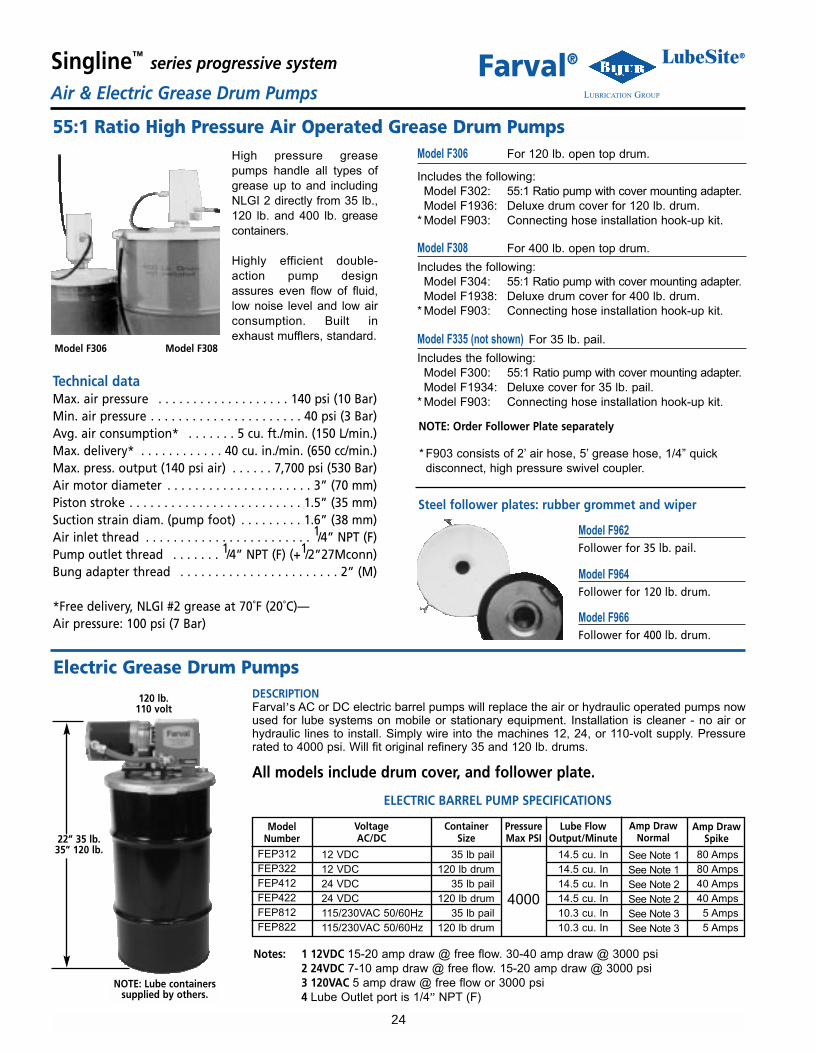
Model F306 For 120 lb. open top drum.
Includes the following:Model F302: 55:1 Ratio pump with cover mounting adapter.Model F1936: Deluxe drum cover for 120 lb. drum.
* Model F903: Connecting hose installation hook-up kit.
Model F308 For 400 lb. open top drum.
Includes the following:Model F304: 55:1 Ratio pump with cover mounting adapter.Model F1938: Deluxe drum cover for 400 lb. drum.
* Model F903: Connecting hose installation hook-up kit.
Model F335 (not shown) For 35 lb. pail.
Includes the following:Model F300: 55:1 Ratio pump with cover mounting adapter.Model F1934: Deluxe cover for 35 lb. pail.
* Model F903: Connecting hose installation hook-up kit.
NOTE: Order Follower Plate separately
* F903 consists of 2� air hose, 5� grease hose, 1/4� quickdisconnect, high pressure swivel coupler.
Technical dataMax. air pressure . . . . . . . . . . . . . . . . . . . 140 psi (10 Bar)Min. air pressure . . . . . . . . . . . . . . . . . . . . . . 40 psi (3 Bar)Avg. air consumption* . . . . . . . 5 cu. ft./min. (150 L/min.)Max. delivery* . . . . . . . . . . . . 40 cu. in./min. (650 cc/min.)Max. press. output (140 psi air) . . . . . . 7,700 psi (530 Bar)Air motor diameter . . . . . . . . . . . . . . . . . . . . . 3” (70 mm)Piston stroke . . . . . . . . . . . . . . . . . . . . . . . . . 1.5” (35 mm)Suction strain diam. (pump foot) . . . . . . . . . 1.6” (38 mm)Air inlet thread . . . . . . . . . . . . . . . . . . . . . . . . 1/4” NPT (F)Pump outlet thread . . . . . . . 1/4” NPT (F) (+1/2”27Mconn)Bung adapter thread . . . . . . . . . . . . . . . . . . . . . . . 2” (M)
*Free delivery, NLGI #2 grease at 70˚F (20˚C)—Air pressure: 100 psi (7 Bar)
55:1 Ratio High Pressure Air Operated Grease Drum PumpsHigh pressure greasepumps handle all types ofgrease up to and includingNLGI 2 directly from 35 lb.,120 lb. and 400 lb. greasecontainers.
Highly efficient double-action pump designassures even flow of fluid,low noise level and low airconsumption. Built inexhaust mufflers, standard.
Steel follower plates: rubber grommet and wiper
Model F306 Model F308
DESCRIPTIONFarval’s AC or DC electric barrel pumps will replace the air or hydraulic operated pumps nowused for lube systems on mobile or stationary equipment. Installation is cleaner - no air orhydraulic lines to install. Simply wire into the machines 12, 24, or 110-volt supply. Pressurerated to 4000 psi. Will fit original refinery 35 and 120 lb. drums.
All models include drum cover, and follower plate.
Notes: 1 12VDC 15-20 amp draw @ free flow. 30-40 amp draw @ 3000 psi2 24VDC 7-10 amp draw @ free flow. 15-20 amp draw @ 3000 psi3 120VAC 5 amp draw @ free flow or 3000 psi4 Lube Outlet port is 1/4” NPT (F)
Electric Grease Drum Pumps
ELECTRIC BARREL PUMP SPECIFICATIONS
ModelNumber
VoltageAC/DC
ContainerSize
PressureMax PSI
120 lb.110 volt
Lube FlowOutput/Minute
Amp DrawNormal
Amp DrawSpike
FEP312FEP322FEP412FEP422FEP812FEP822
12 VDC12 VDC24 VDC24 VDC115/230VAC 50/60Hz115/230VAC 50/60Hz
35 lb pail120 lb drum
35 lb pail120 lb drum
35 lb pail120 lb drum
4000
14.5 cu. In14.5 cu. In14.5 cu. In14.5 cu. In10.3 cu. In10.3 cu. In
See Note 1See Note 1See Note 2See Note 2See Note 3See Note 3
80 Amps80 Amps40 Amps40 Amps
5 Amps5 Amps
22” 35 lb.35” 120 lb.
NOTE: Lube containerssupplied by others.

25
Singline™ series progressive system LubeSite®
LUBRICATION GROUPAir/OilFarval®
Farval air/oil systems deliver ultra efficient lubrication and cooling to heavy duty, high performancebearings operating in adverse conditions.
Customized air/oil stations and zone boxes deliver precise oil and air flow to bearings and gears forsustained peak performance.
Assemblies comprise Farval’s series progressive divider valves to deliver a range of air/oil outputs.Airflows can be fixed or adjustable to each bearing port. Air/oil modules are assembled direct to theM2500 divider valve.
Pump stations can be air operated or electric motor driven. A full line of Farval controller andmonitoring packages are provided to control system performance.
BASIC PRINCIPLE OF AIR/OIL LUBRICATION
The valves are mounted directly on top of the Farval Series M2500 divider valves.
Oil is discharged from the alternate outlet ports on top of the M2500 valve assembly and enters theH/F/A2500 section. Compressed air enters the assembly through the center of the air/oil block, mixeswith the oil and goes out the outlet port.
The oil is carried along the inside of the tube by the air flow, and when piped into a bearing the oillubricates the bearing and air flow acts to prevent moisture and contamination from entering the bear-ing and assists in reducing bearing temperature.
INDUSTRIES AND APPLICATIONS INCLUDE:
STEEL - Spindles, Saws, Rolling Mills, Roller Tables, Levelers, Continuous Casters, Fan Bearings, Pinch &Shape Roll, Guides, Gears, Work Roll & Back Roll
PAPER - Chains, Gear Cases, Roll Additions, Dryers
GENERAL - Any bearing that can benefit from air/oil pressurization or application

Max Air Flow F/A2500=5 SCFM H2500=20 SCFMMax Air Flow 100 PSI (7 BAR)Seals VitonMaterial Anodized Aluminum
26
Singline™ series progressive system LubeSite®
LUBRICATION GROUPAir/OilFarval®
Features That Make the Difference• Air/Oil mixing sections mount directly onto Farval M2500 Series and most competitors modular divider assemblies.
• Air flow adjustability at each lube point via adjusting screws. Optional fixed (tamper-proof) orifice air flow unitsare also available.
• Ability to mount 1 to 8 air/oil valves on a divider assembly, serving from 1-16 air/oil lube points per assembly.
• Manifolds can dispense oil only or air/oil from different ports on the same divider assembly.
• Oil volume is supplied through standard discharge sections ranging from .005 to .008 cu. in. per discharge.
FARVAL SERIES AIR/OIL VALVES
3 SECTION AIR/OIL VALVE ASSEMBLY
F2500/A2500/H2500 SPECIFICATIONS
ORDERING INFORMATION
F2500 A2500 H2500Inlet FIT14064B2 FIT14064B2 34134 & U1720120SEnd PLU14065B PLU14065B 34136Mixing Valve* F2500B A2500B H2500BTie Rod (2 req’d) N/A N/A MCR2505-3 thru 8Nut (2 req’d) N/A N/A U251A
Note: *Mixing Valve’s include all seals, mounting screws, flush fit plugs, etc.
3.5”(88.9)
3.5”(88.9)
1/4”NPTF
Oil Inlet
3/4”NPTF
Air Inlet
H2500SERIES
1/4” NPTFAir/Oil Outlets
1/8” NPTFAir/Oil Outlets
F2500(Fixed Output)
A2500(Adj. Output)
3.0”(76.2)
1/4” NPTFOil Inlet
3/8” NPTFAir Inlet

27
Singline™ series progressive system LubeSite®
LUBRICATION GROUPAir/OilFarval®
These units can handle systems up to 50 points.They include Reservoir, Pump, Controller, Air &Oil Filters, and Divider Valve all mounted in a freestanding NEMA 12/13 enclosure, with lights andlockable doors.
Use of Farval remote zone boxes permit over 1000 bearingpoints to be lubricated from one central air/oil station.
Each box contains a controller-monitor to program anelectric zone shut-off valve feeding a master oil dividervalve.
An air/oil zone box contains all necessary airflow controlvalves and high-low air/oil pressure switches with LEDreadouts. Oil flow control valves and required secondaryfeed lines to supply the network served are included.
All components are assembled in a NEMA 12/13 freestanding enclosure with bulk headed air, oil and electricoutlets.
The central pump station will include a 50-1000 gallon tank; low level switch; spin-on oilfill filter; two (redundant) air operated barrelpumps; two isolation air and oil valves; andFRL.
Due to complexity of these air/oil systemsFarval recommends you contact yourRegional Sales Manager for assistance.
SELF CONTAINED AIR/OIL SYSTEM
AIR/OIL ZONE BOX
CENTRAL PUMPING STATION

28
Singline™ series progressive system LubeSite®
LUBRICATION GROUPStrainers & TimersFarval®
LS Strainers
*BasicLetter
Identification
PipeTapSize
Dirty ScreenIndicatorOption
Dirty Screen(Usage at
Minimum OperatingTemperature
**MicroSwitchOption
*LS - �LineStrainer�
02 - 1Ú4�03 - 3Ú8�
1 - withoutindicator2 - with
indicator
03 - 25 micron screen(oil only up to
500 SSU)06 - 150 micron screen
(oil only up to2000 SSU)
20 - 500 micron screen(oil over 2000 SSU & all
grease)
No Number-
No microswitch
5 - microswitch
TYPICAL ORDERING CODELS - 02 2 03 5
*This must appear in all orders for strainer assemblies.**Micro Switch available ONLY with Dirty Screen Indicator (2 Option).
Example: LS-03-120 is the order code for a 3/8� P.T.Strainer without indicator and with a 500 micron screen.
REPLACEMENT SCREENS
Part No. DESCRIPTION
LS-02-05-103
LS-02-05-106
LS-02-05-120
25 MICRON SCREEN (OIL ONLY UP TO 500 SSU)
150 MICRON SCREEN (OIL ONLY UP TO 2000 SSU)
500 MIICRON SCREEN (OIL OVER 2000 SSU & ALL GREASE)
DESCRIPTION1. LS line strainers remove foreign particles from grease and oil
lines in lubricating systems. Withstand up to 5000 psi working pressure non-shock.
2. Flow rate and ratio of open screen area to pipe diameter are:
3. The dirty screen indicator option requires a differentialpressure between 300 and 500 psi for activation.
MODEL SM-C DIRECT CURRENT VOLTAGE CONTROLLEROPERATION
Various timer and count based models available with adjustable‘ON’ and ‘OFF’ ranges to control pneumatic or electronic motor-driven lubrication systems. The controller has the ability to detectabnormal operating situations.
Unit has lapsed time feature. After power interruption, controllercompletes remaining time or cycles.
Low lubricant levels in lubricator switch can be monitored by con-troller.
A built-in LED display monitors preset program operation LED’sdisplay status of electrical inputs.
SPECIFICATIONS• 12 and 24VDC models available• Suitable for electric motor or solenoid
(pneumatic pump)• Can monitor cycle switch input and low
level input• Enclosure rating IP67• Vibration 5G• Ambient temperature -4ºF to 110ºF• Alarm switch normally open, contact
rating 30 watts maximum
CONTROLLER STATUS LED�s• Red Steady - Lubrication Cycle• Yellow Steady - Alarm• Green Steady - Power Supply On• None Lit - No input power to controller
INSTALLATIONMount the controller in a clean area with easy access for pro-gramming and visual checking. Mount controller on a flat sur-face, free of vibrations.
PART NO.33346-1
33346-2
33346-3
33346-4
OPERATING CHARACTERISTICSCount Based ‘ON’ Period (Input Cycles) 0-9999 cycles
‘OFF’ Period 0-9999 minutesTime Based ‘ON’ Period 0-999 cycles
‘OFF’ Period 0-9999 minutesCount Based ‘ON’ Period (Input Cycles) 0-9999 cycles
‘OFF’ Period 0-9999 minutesTime Based ‘ON’ Period 0-999 cycles
‘OFF’ Period 0-9999 minutes
POWER INPUT24 V DC±10%
24 V DC±10%
12 V DC±10%
12 V DC±10%
PEAK CURRENT3 amps
3 amps
5 amps
5 amps
3.5� (88)
6.1�
(154
)

29
Singline™ series progressive system LubeSite®
LUBRICATION GROUPMiscellaneous ControllersFarval®
GeneralA compact timer which mounts directlyto a solenoid valve having DIN 43650Form A electrical terminations.
Unit has four operating modes, witheight time ranges. Final time range set-tings are adjusted by potentiometers.
Two red light emitting diodes indicatepower ‘ON’ and output energized (sole-noid ‘ON’).
ORDER SEPARATETIMER - PART NO. 24476SOLENOID VALVE - PART NO. 20311-3110/120 50/60 Hz3-Way-2-position - normally closed1/8” NPT Ports150 PSi Max
SS2200 CONTROLLER• Simple three key programming• Controls both single line and dualine
lubrication systems• Operates electric or air driven pumps• Time or machine cycle based operation• Programmable for remote fault
indicationand emergency machine shutdown
• LED indicators and numerical displaysmonitor system operation
• EEPROM permanently storesprogrammingwithout battery backup
The Farval SS2200 is a microprocessor-basedprogrammable controller designed to oper-ate Farval Single line and Dualine centrallubrication systems. the SS2200 is housed in aNEMA 4X polycarbonate enclosure with atransparent cover. Visible through the coverare LED indicators for Idle, Lube and Faultmodes, and a three-digit numerical displayused for programming and monitoring lubesystem operation.
2.91”
6.89”
4.92”
NOTE: A 12-30 VDC MODEL IS AVAILABLE - PART #SS2200DCA 220 VAC MODEL IS AVAILABLE - PART #SS2200-220
SPECIFICATIONSINPUT . . . . . . . . . . . . . . . . . . . . . 115 VAC-50/60 Hz.
Over voltage protectedOUTPUTS:
Pump . . . . . . . . . . . . . . . . . . Pulsed or Continuous,Form A, 115 VAC,5 Amp. Inrush, 2 Amp. Continuous
Cycle Switch . . . . . . . . . . . . . 12-16 VDC, 12-16 ma.DCFault Switches . . . . . . . . . . . 12-16 VDC, 12-16 ma.DC
FAULT RELAY CONTACTS . . . . . . . 2 Amp., 125 VACENCLOSURE . . . . . . . . . . . . . . . . . NEMA 4X, PolycarbonateAMBIENT TEMPERATURE . . . . . . +20ºF. to 120ºF.VIBRATION` . . . . . . . . . . . . . . . . . 1.5gPERMANENT MEMORY . . . . . . . . EEPROM (No Battery)
PROGRAMMINGIDLE TIME . . . . . . . . . . . . . . . . . . 1-999 Hours, 1-999 Minutes
1-999 or 10-9990 MachineCountsCYCLE COMPLETION TIME . . . . . 1-999 MinutesCYCLE SWITCH COUNTS . . . . . . . 1-99 CountsPULSED OUTPUT ON-TIME . . . . . 1-99 SecondsPRELUBE ON POWER-UP . . . . . . . Yes/noFAULT RELAY . . . . . . . . . . . . . . . . Normally Energized/
Normally De-energizedCONTROLLER . . . . . . . . . . . . . . . . On/Off
24476 TECHNICAL DATASupply voltage . . . . . . . 110-230V, 50/60 Hz, (+ - 10%)Power Consumption . . . 1.0W maximumSwitching Load . . . . . . . lmax=0.5 A at supply voltage
110/230V, 50/60 HzClassification . . . . . . . . . Ip 65, air gaps and leakage
paths according to VDE 0100Body Material . . . . . . . . Polyamide plasticWorking Temp. Range . 32º-130ºF (0º-55ºC)Indicator . . . . . . . . . . . . LED connected power supply
LED energized loadAdjustment . . . . . . . . . . Basic function and time range
via DIP switch settingsPrecision time adjustmentvia potentiometer
Time Range . . . . . . . . . . Adjustable from .5 secondsto 10 hours
TIMER AND SOLENOID VALVE FOR PNEUMATIC OPERATED PUMPS

2M (01/05)
Farval® Whatever your automaticlube requirement…
We have the solution!
Let 75+ Years Of Experience Design Your Next Lube System
Farval has been a manufacturer of automatic lubricating systems for over 75 years. We offer a complete line of pumps, valves,controllers, and accessories. Our pump line includes manual, air, electric, and hydraulic actuated models. Farval’s valve offer-ing is the most comprehensive in the industry. We manufacture oil and grease Dualine valves, series progressive modularvalves, and injectors. Farval also offers air/oil mixing modules, oil flow meters, and single point lubricators.
ADVANTAGE PRINTING
Your local distributor:
Bijur Lubrication Group BIJUR® DELIMON®-DENCO FARVAL® LUBESITE®9001:2000QUALITY
CERTIFIED
Farval® Lubrication Systems, Inc.2685 Airport Road • Kinston, NC 28504Tel. 800-227-1063 • Fax: 252-527-9232
website: www.farval.com • e-mail: [email protected]