sinowon rockwell hardness tester shr-150m operation manual en
DESCRIPTION
This file is the operation/instruction manual for Sinowon brand Rockwell Hardness Tester Manual type model SHR-150M.TRANSCRIPT

Vexus SHR-150M
Code #: 811-111
Manual Rockwell Hardness Tester
Instruction Manual
DongGuan Sinowon Precision Instrument Co.,Ltd.

1
Precautions
1.Many thank for purchasing our electronic Rockwell hardness tester Vexus
SHR-150M you are requested to Read carefully the Instruction Manual
before operating the present instrument in order to know the operational
procedures and the cautions for the usage so that the damages and the
safety accidents caused by the incorrect operations may be avoided.
2.Strip off the packing Belts and the Anti-shock Adhesive Tapes Carefully
When the Instrument is Installed and Tried.
3.During the loading and unloading as well as the dwell t ime of the test
force, don’t rotate the carriage-changing hand-wheel on the rotary
wheel.
4.Our company makes every effort to improve the quality of the hardness
tester and hence changes the structure from time to time. In case the
contents of the Instruction Manual is a bit not in conformity with the structure
of the instrument, there would not any further notice to be given, for which
we would like to beg your pardon.
2
Contents
1. Brief Introduction...................................................................3
2. Technical Specifications .......................................................4
3. Rockwell Scale, Indenter, Test Force and Applicable Range
of Rockwell Hardness Testing..................................................5
4. Installation of Hardness Tester Vexus SHR-150M......................6
5. Correct Usage of Hardness Tester Vexus SHR-150M.................7
6. Maintenance and Precautions..............................................9
7.Accessories (Packing List).....................................................10

Brief Introduction
3
1. Hardness is one of the important criteria of the mechanical functions of the materials,
and the hardness test is the important means to judge the quality of the metallic materials
or parts, As the metallic hardness ha mutual correspondent relations with other mechanical
functions, the majority of the metallic materials can calculate the other mechanical
functions such as the strength, the fatigue, the evolutionary change and the degree of
being worn out can be approximately inferred from the hardness shown by the test.
2. The manual Rockwell hardness fester is a popularly-used hardness testing instrument
to measure the Rockwell hardness of the materials. The speed of loading the test force
is regulated by the buffer whereas the change of the test force is made by rotating the
carriage-changing hand-wheel. The operation of the present instrument is simple, its
functions are stable, and its use is, therefore, widely spread.

4
Technical Specifications
1. The Test Force: 98.07N (10kg); Tolerance: ± 2.0%
2. The Total Test Force: 588.4N(60kg),980.7N(100kg),1471N(150Kg); Tolerance: ± 1.0%
3. The Indenter Specification:
3.1 The Diamond Rockwell Indenter
3.2 The φ1.5875 mm Ball Indenter
4. The Power Source: AC220V±5%/50 Hz;AC110V±5%/60 Hz
5. Time-delayed control: 2-60 seconds, adjustable
6. The Max. Height of the Specimen: 175 mm
7. The Distance from the Indenter Center to the Instrument Body: 165mm.
8. The Overall Dimension of the Tester: 520×215×700mm (Length × Width × Height).
9. The Net Weight of the Tester: 78kg (Approx).
10. The Allowable Tolerance of Hardness Display Value of the Hardness Tester (Table 1).
Hardness ScaleHardness Range of the Standard
Hardness BlocksMax. Tolerance of Hardness
Display Value
(>50~75)HRG ±4.5HRG
(>75~94)HRG ±3HRG
HRH (80~100)HRH ±2HRH
HRK
(40~60)HRK ±4HRK
(>60~80)HRK ±3HRK
(>80~100)HRK ±2HRK
HRA(20~75)HRA ±2HRA
(>75~88)HRA ±1.5HRA
HRB
(20~45)HRB ±4HRB
(>45~80)HRB ±3HRB
(>80~100)HRB ±2HRB
HRC (20~70)HRC ±1.5HRC
HRD(40~70)HRD ±2HRD
(>70~77)HRD ±1.5HRD
HRE(70~90)HRE ±2.5HRE
(>90~100)HRE ±2HRE
HRF(60~90)HRF ±3HRF
(>90~100)HRF ±2HRF
HRG
(30~50)HRG ±6HRG
Table 1
5
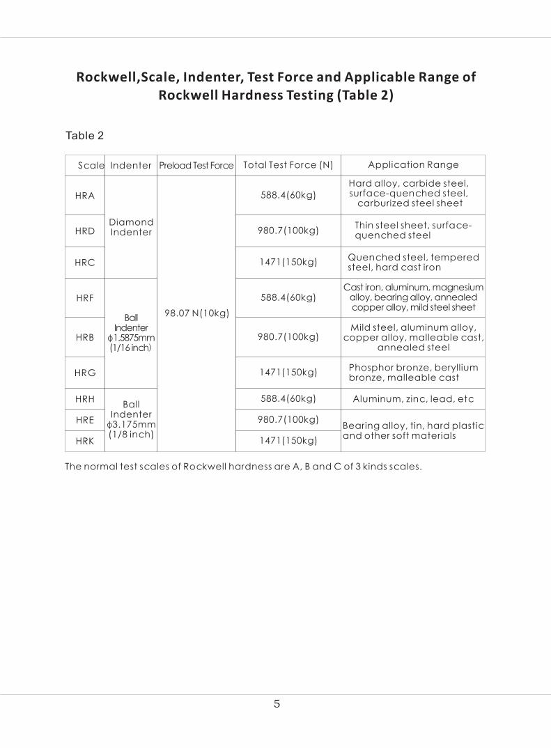
Rockwell,Scale, Indenter, Test Force and Applicable Range ofRockwell Hardness Testing (Table 2)
HRB 980.7(100kg)Mild steel, aluminum alloy,
copper alloy, malleable cast, annealed steel
HRG 1471(150kg)Phosphor bronze, beryllium bronze, malleable cast
HRHBall
Indenter φ3.175mm(1/8 inch)
Aluminum, zinc, lead, etc
HRE 980.7(100kg)Bearing alloy, tin, hard plastic and other soft materials
HRK 1471(150kg)
The normal test scales of Rockwell hardness are A, B and C of 3 kinds scales.
Scale Indenter Preload Test Force Total Test Force (N) Application Range
HRA
Diamond Indenter
98.07 N(10kg)
588.4(60kg)
588.4(60kg)
Hard alloy, carbide steel, surface-quenched steel,
carburized steel sheet
HRD 980.7(100kg)Thin steel sheet, surface-quenched steel
HRC 1471(150kg)Quenched steel, tempered steel, hard cast iron
HRF
Ball Indenter
φ1.5875mm(1/16 inch)
588.4(60kg)Cast iron, aluminum, magnesium
alloy, bearing alloy, annealed copper alloy, mild steel sheet
Table 2

6
1. The working condition of the hardness tester
1.1 Under the room temperature between 10~30℃;
1.2 The relative humidity in the test room shall not be over 65%;
1.3 In an environment free from vibration and shock; without corrosive in surroundings.
2. The Unpacking of the Hardness Tester
2.1 Cut the belts on packing box, loosen off the screws at bottom of packing box,
remove the upper body of packing box, and take out accessories kit.
2.2 Unscrew two (2) M10 outer hexagonal bolts under the bottom plate with a spanner,
to separate the hardness tester from the bottom plate (take care of the safety).
2.3After unpacking, the hardness tester shall be placed on a stable working table
horizontally, with horizontal deviation less than 1mm/m. A hole shall be drilled at an
appropriate location on the working
table (see Fig.1) to enable the Up and
Down Lead Screw to operate properly.
We suggest the height of working table
should be about 500mm.
3. The placement of the hardness tester (Fig.2)
The Installation of the Hardness Tester Vexus SHR-150M
φ90
130
550
20
0
Fig.1
Fig.2
1.Dial;
2.Handle for loading and unloading;
3.Fixing Screw for Indenter;
4.Indenter; 5.Testing Table;
6.Operating Lever;
7.Hand wheat for Changing the Carriage;
8.Rotary wheel;
9.Back cover;
10.Upper cover

7
4 The Installation of the Weight Group (Fig.3)
4 . 1 A t t h e t o i n s t a l l t h e w e i g h t s , t h e
c a r r i a g e - l o a d i n g a n d u n l o a d i n g
h a n d l e ( 2 ) s h o u l d b e i n t h e f r o n t
posi t ion and the inst rument should
b e i n t h e s t a t e o f a b s e n t c a r r i a g e .
4 . 2 T a k e o u t t h e s e t s o f w e i g h t s f r o m
t h e a c c e s s o r i e s k i t a n d r u b t h e m
c lean. Rotate the car r iage-changing hand wheel (7) to the point of 588 .4 ,
and take out the hanging lever (12) f rom the back cover and inser t the set
o f w e i g h t s ( 1 6 ) i n t o t h e h o l e , a n d t h e s c r e w t i g h t t h e n u t ( 1 7 ) a n d h o o k
t h e h a n g i n g p o l e i n t o t h e h o l e a t t h e e n d o f t h e l e v e r . P l a c e t h e s e t o f
weights B(15) and the set of weights C(14) on the two support ing forks (13)
a n d t h e n r o t a t e t h e c a r r i a g e - c h a n g i n g h a n d - w h e e l t o c o m p l e t e a
c i r c l e a n d o b s e r v e w h e t h e r t h e r o u n d p i n s o n t h e t w o s i d e s o f t h e w e i g h t
a r e w e l l p l a c e d i n t o t h e g r o o v e s o n t h e s u p p o r t i n g h o o k . T h e w e i g h t s
s h o u l d b e i n t h e c e n t e r , a n d s o t h e y s h o u l d b e k e p t a w a y f r o m a n y
component part on the inner surface of the instrument body (and therefore
t h e h o r i z o n t a l l e v e l s h o u l d b e c a r e f u l l y a d j u s t e d . )
When the hardness tester is well placed, open the upper cover (10) and the back cover.
Unfasten the rubber belt locking the shaft (22) in the instrument body (Fig.6) and draw
out the protective spacer (25) and the foamed plastic block under the level (11). And
then unfasten off all the cotton belts fixing the movable parts and finally put on the
cover to prevent the dust from entering the instrument.
Fig.4
11.Lever
12. Hanging Rod
13. Fork-Shaped Frame
14. Weight C
15. Weight B
16. Weight A
17. Nut

8
5. The Test Force Selected in Correspondence with the Weight (Table 3)
Scale Test Force(N)Graduated Value on The Load-Switch Hand Wheel
Force on the Weight (Weight Code)
HRA 588.4(60kg) 588.4(60) Hanging Rod + Weight A
HRB 980.7(100kg) 980.7(100)Hanging Rod + Weight A
+Weight B
HRC 1471(150kg) 1471(150)Hanging Rod + Weight A
+Weight B + Weight C
Table 3
6 Method of furnish oil into the oil container (Fig 4)
When the hardness tester is turned out of the factory,
the oil in the container is filled with oil. If there occurs
a leakage during the transport, the client should
prepare a bout 20 milliliters of machine oil and put
it in the container by himself.
The method: Take off the upper cover and push the
carriage-loading and unloading handle backward
and the use the oil pot (21) to pour the oil into the hole in the container cover (19). The volume
of the oil added depends on the handle movement to pour the oil until then handle moves
without any noise of inhaling the air. Too much oil poured would overflow out.
7 Adjust the speed of loading the test force after installing the indenter (4) place the HRC block
with a low hardness on the testing table (5), and rotate the rotary wheel clockwise to lift up
the testing table, when the hardness block touches the indenter, the hands on the dial begin
to move around. When the big hand complete 3 circles, stop rotating the rotary wheel, and
push backward the carriage-loading and unloading handle to observe the rotating speed
of the dial hands. The time range from when the hands begin to move around to when they
stop moving covers 2-6 seconds. You may rotate the regulating nut (18) on the container
body to determine the high speed or the low speed of loading the carriage. To rotate the
nut clockwise makes a high speed white to rotate it otherwise reduces the speed. Below
there is a reference table showing
the speeds of the loading time, the
dwell time and the unloading time
of the test force (table 4).
Fig 4
18 Regulating Nut
19Oil container cover
20 Oil container body
21 Oil pot
Loading Time Dwell Time Unloading Time
2~6 seconds 5 seconds 2~3 seconds
table 4

9
Correct Usage of Hardness Tester Vexus SHR-150M
Fig.5
1 The preparatory works before the operation
1.1 Make sure that the surface of the specimen
should be smooth and clean without any dirt,
oxidized layer, sunken spot or processing
trace. The supporting surface of the specimen
and the plane of the testing table should be
clean in order to have an intimate touch.
1.2 The min. thickness of the specimen should
more than 10 times greater than the be
depth of the indentation. After the test, there should be not visible deformed traces
on the back of the specimen. For the relation between the min. thickness of the
specimen and the hardness. See Fig. 5.
1.3 The specimen should be steadily placed on the testing table and should not be slightly
moved during the operation of loading and unloading the test force so as to assure
that the test force falls on the specimen vertically.
1.4 Choose the suitable testing table according to the shape and dimension of the specimen.
If the specimen has an irregular shape, it is necessary to make by our selves the fixture
according to its actual geometrical shape in order to obtain a reliable hardness value.
1.5 In case the specimen is a cylinder in shape, it is necessary to use the V-shaped testing
table. When the diameter of the specimen is less than 38(25) mm, its testing result should
be readjusted. The adjusted values are generally positive figures (Table 5).
2 Operational Procedure of the Hardness Tester
2.1 In order to choose the scale (Table 2) according to the softness and hardness of the
specimen, rotate the carriage-changing hand-wheel to determine the total test force.
All the changes of the test force should make the instrument stay in the state with all the
test forces unloaded. (The loading and unloading handle stays in the front position)
2.2 Put on the indenter with the notch of the indenter handle facing the screw; tighten
slightly the fixing screw (3), and then place the specimen on the testing table.

10
Hardness Value(HR)
Diameter(mm)of the Columned Specimen
6 10 13 16 19 22 25 32 38
Revised Value of Rockwell Scales A, C, D(HR)
20
25
30
35
40
45
50
55
60
65
70
75
80
85
90
3.0
2.5
2.0
1.5
1.5
1.0
1.0
0.5
0.5
0.5
3.0
2.5
2.0
2.0
1.5
1.0
1.0
1.0
0.5
0.5
0.5
0
3.0
2.5
2.0
2.0
1.5
1.5
1.0
1.0
1.0
0.5
0.5
0.5
0.5
0
2.5
2.5
2.0
1.5
1.5
1.0
1.0
1.0
0.5
0.5
0.5
0.5
0.5
0
0
2.0
2.0
1.5
1.5
1.0
1.0
1.0
0.5
0.5
0.5
0.5
0.5
0.5
0
0
1.5
1.0
1.0
1.0
1.0
0.5
0.5
0.5
0.5
0.5
0.5
0
0
0
0
1.5
1.5
1.5
1.0
1.0
1.0
0.5
0.5
0.5
0.5
0.5
0.5
0
0
0
1.0
1.0
1.0
0.5
0.5
0.5
0.5
0.5
0
0
0
0
0
0
0
1.0
1.0
0.5
0.5
0.5
0.5
0.5
0
0
0
0
0
0
0
0
Hardness Value(HR)
Diameter(mm)of the Columned Specimen
6 10 13 16 19 22 25
Revised Value of Rockwell Scales B, F, G(HR)
20
30
40
50
60
70
80
90
100
5.0
4.0
3.5
5.0
4.0
3.5
3.0
2.5
5.0
4.5
4.0
3.5
3.0
2.5
2.0
1.5
4.5
4.5
4.0
3.5
3.0
2.5
2.0
1.5
1.5
4.0
3.5
3.0
3.0
2.5
2.0
1.5
1.5
1.0
3.5
3.0
2.5
2.5
2.0
2.0
1.5
1.5
1.0
3.0
2.5
2.5
2.0
2.0
1.5
1.5
1.0
0.5
Table 5
2.3 Rotate the rotary wheel to lift up the lever so that the specimen may move solely to
touch the indenter without any shock until the little hand of the comparator moves to
the red point from the black point meanwhile the long hand points at the spot “C”
after three cycles. The deviation of the long hand should not surpass 5 graduated Value.
If the deviation has surpassed this limit, one should not make it move back. It is necessary
to lower the lever and re-select the position of the testing point (When the HRB hardness
is tested the long hand should point at “B”). At this t ime , the init ial test force of
98.07N (10kg) is loaded. Rotate the dial to let the hand point at “C”.
2.4 Push the handle back slowly and make sure that the test force is loaded within 2-6
seconds. The dwell time of the test force is seconds. And then pull the handle forward
steadily within 2-3 seconds to unload the main test force but keep the initial test force.

11
2.5 At this time, the figure at which the long hand of the comparator points is the hardness
of the specimen. (When the HRB hardness is tested, its value should be read in the
inner cycle.)
2.6 Rotate the rotary wheel backward to lower the testing table. Change the testing point
and repeat the above-described operation.
2.7 No less than 5 testing points should be chosen for the specimen (the first point is not
counted.) For the test of a great number of specimen, the number of the testing points
could be rationally reduced.
Adjustment of the Indicated Hardness Values (Fig. 6)
22. Connecting Rod 23. Screw Rod
24. Screw 25. Protecting Gasket
3 Adjustment of the Indicated Hardness Values (Fig. 6)
The precision of the Value indication of the hardness tester is calibrated before it is
turned out of the factory. If there occur some errors due to transportation, the testing
operators could make certain adjustments on the base of knowing the structural principles
of the instrument. The method is as follows: After taking off the upper cover, if they find
the indicated value of the test is lower than
that of the standard block, they should loosen
the nut M4 (23) and rotate the screw (24)
clockwise slowly and make zero on the dial,
and then fasten the nut to test the indicated
value again unt i l i t i s adjusted into the
tolerance range (Table 1). If the indicated
value of the test is higher than the standard
hardness, rotate the screw backward.
Note: During the loading and unloading of the test force, it is prohibited to rotate the
Load-Change Hand Wheel. The force rotation would make the components inside the
instrument dislocated, and cause the disorder to the test force.
Maintenance and Precautions
12
1. The testing operators should observe the rules of operations and be able to calibrate
the instrument with the standard blocks before the test. If the instrument is not often
used, after the instrument is started, they should make several tests with the blocks.
Once the instrument is stable, it is time to carry out the hardness test.
2 . I f the inst rument needs to be moved, the tester should be vert ical dur ing the
transportation. It is prohibited to carry the instrument horizontally. Meanwhile the
weights and the hanging lever should be dismounted during the transportation.
3. At the loading, unloading and dwell t ime of the test force during the testing, It is
prohibited to rotate the carriage-changing hand wheel.
4. The standard blocks are used only on the working surface. The distance between
two neighbor indentations and that of the indentation centre to its edge should not be
less than 3 mm. Their usage cycle is two years,
5. Fixing of the Ordinary Breakdowns of the Hardness Tester
When the tester has broken down or is out of order, it is necessary to communicate with
the unit concerned for the repair. The ordinary breakdowns can be solved by the
operators themselves. (Table 6)

13
Table 5
Phenomenon Possible Causes Method Used
The long hand of the
dial is deviated and
does not point at the
zero
1.Change the diamond or ball
indenter.
2.Install the weights awarding
to Fig.3.
3.Put the instrument in a horizontal
position with a level according
to the requirements in 4.2.3.
4.Lower the protective cover
and let it be loner than the level
of the lever, and then tighten
the screw.
5.Select the test force and the
indenter according to the
requirements set up in Table.2.
The adjustment of the indicated
hardness value may cause the
deviation of the long hard.
Refer to Fig.6, and then loosen
the nut and rotate a l itt le the
screw M4 (23) to point at the
zero. Fix the screw and fasten
the nut.
There a pears a shock
during the loading of
the test force or a noise
o f i n h a l i n g t h e a i r
during the unloading
The oil volume is not sufficient in
the container.
Add oil according to the
requirements shown in Fig.4
Great errors in the in
dication of the
hardness value
1. The indenter is broken down
2. Wrong disposition of the weights
3. The weights rub against the
inner wall of the instrument
due to non horizontal level
of the position of the instrument
4. The protective cover is higher
than the lever
5. The wrong selection of the total
test force or of the indenter

14
Accessories (Packing List)
No. Description of Goods
Diamond Rockwell Indenter
φ1.5875mm Ball Indenter
Hardness Block(85-100)HRB
Hardness Block(20-33)HRC
Fuse 2A
Power Cable
Weight A
Level Screw
Horizontal Regulating Screw
Usage Instruction Manual
1
2
3
4
5
6
7
8
9
10
11
12
13
14
1 PC
1 PC
1 PC
1 PC
1 PC
1 PC
1 PC
1 PC
2 PCS
1 PC
1 PC
1 PC
4 PCS
1 Copy
Code#
811-401
811-411
811-541
811-511
811-521
Quantity
φ 150mm flat anvil
φ 55mm flat anvil
φ 55mm V-shape anvil
Hardness Block(57-70)HRC
811-621
811-601
811-611
811-811
811-801
811-711
811-901
811-921
Vexu s SHR -150M
Weight B
Weight C
811-721
811-731
1 PC
1 PC
15
16

Authorized Distributors:
DongGuan, China