sinumerik safety integrated, function manual · 2015-03-17 · installation, operation, or...
TRANSCRIPT

Valid for
ControlSINUMERIK 840D slSINUMERIK 840D sl (export version)
DriveSINAMICS S120
Software versionNCU system software 1.5NCU system software 2.5HMI Advanced 7.5
05/08 Edition
SINUMERIK Safety Integrated
SINUMERIK 840D sl/SINAMICS S120
Function ManualFunction ManualFunction ManualFunction ManualFunction ManualFunction ManualFunction ManualFunction ManualFunction ManualFunction ManualFunction ManualFunction ManualFunction ManualFunction Manual
Regulations and Standards 1
Brief Description 2
System Features 3
Safety Functions Integrated in the Drive 4
Basic Information onSafety Functions Integratedin the System/Drive 5
Safety Functions Integratedin the System/Drive 6
Sensor/Actuator Connection 7
Data Descriptions 8
Commissioning 9
Diagnostics 10
Interaction with Other Functions 11
Appendix A
Index I

SINUMERIK® documentation
Printing history
Brief details of this edition and previous editions are listed below.
The status of each edition is shown by the code in the ”Remarks” column.
Status code in the ”Remarks” column:
A New documentation.. . . . . B Unrevised reprint with new Order No.. . . . . C Revised edition with new status. . . . . .
If factual changes have been made on the page since the last edition, this is indicatedby a new edition coding in the header on that page.
Edition Order No. Remarks03/06 6FC5 397–4BP10–0BA0 A03/07 6FC5 397–4BP10–1BA0 C05/08 6FC5 397–4BP10–2BA0 C
TrademarksAll product designations may be trademarks or product names of Siemens AG or suppliercompanies whose use by third parties for their own purposes could violate the rights of theowners.
© Siemens AG 2008 All rights reserved.
We have checked that the contents of this publication agree with thehardware and software described here. Nevertheless, differencesmight exist and therefore we cannot guarantee that they arecompletely identical. The data in this document is regularly checkedand the necessary corrections are included in subsequent editions.Suggestions for improvement are also welcome.
Subject to change without prior notice.
Siemens–AktiengesellschaftPrinted in the Federal Republic of Germany Siemens–Aktiengesellschaft
3ls

Preface05.08
iii© Siemens AG 2008 All Rights ReservedSINUMERIK 840D sl/SINAMICS S120 SINUMERIK Safety Integrated (FBSI sl) -- 05.2008 Edition
Preface
SINUMERIK documentation
The SINUMERIK documentation is organized in 3 parts:
S General documentation
S User documentation
S Manufacturer/Service documentation
An overview of publications, which is updated monthly and provides informationabout the language versions available, can be found on the Internet at:http://www.siemens.com/motioncontrolFollow menu items -- ”Support” --> ”Technical documentation” --> ”Orderingdocumentation” -- > ”Printed documentation”.
The Internet version of DOConCD (DOConWEB) is available at:http://www.automation.siemens.com/doconweb
Information about training courses and FAQs (frequently asked questions) is avail-able on the Internet under:http://www.siemens.com/motioncontrol and there under the menu item ”Support”
Target group
This documentation is intended for manufacturers/end users of machine tools andproduction machines who use SINUMERIK 840D sl and SINAMICS S120 and theintegrated safety functions (SINUMERIK Safety IntegratedR).
Standard scope
This documentation describes the functionality of the standard scope. Extensionsor changes made by the machine manufacturer are documented by the machinemanufacturer.Other functions not described in this documentation might be executable in thecontrol. However, no claim can be made regarding the availability of these func-tions when the equipment is first supplied or in the event of servicing.
For the sake of simplicity, this documentation does not contain all detailed informa-tion about all types of the product and cannot cover every conceivable case ofinstallation, operation, or maintenance.

Preface 05.08
iv© Siemens AG 2008 All Rights Reserved
SINUMERIK 840D sl/SINAMICS S120 SINUMERIK Safety Integrated (FBSI sl) -- 05.2008 Edition
Technical support
If you have any technical questions, please contact our hotline:
Europe/Africa
Phone +49 180 / 5050 -- 222
Fax +49 180 / 5050 -- 223
Internet http://www.siemens.com/automation/support--request
America
Phone +1 423 262 2522
Fax +1 423 262 2200
E--mail mailto:[email protected]
Asia/Australia
Phone +86 1064 719 990
Fax +86 1064 747 474
E--mail mailto:[email protected]
Note
National phone numbers for technical support are provided under the followingInternet address: http://www.siemens.com/automation/service&support
Calls from the German fixed line network are charged (e.g. at 0.14 €/min).Charges of other phone services may be different and may vary.
Questions about this documentation
If you have any queries (suggestions, corrections) regarding this documentation,please send a fax or e--mail to the following address:
Fax +49 9131 98 63315
E--mail mailto:[email protected]
A fax form is available at the end of this document.
SINUMERIK Internet address
http://www.siemens.com/sinumerik

Preface05.08
v© Siemens AG 2008 All Rights ReservedSINUMERIK 840D sl/SINAMICS S120 SINUMERIK Safety Integrated (FBSI sl) -- 05.2008 Edition
Standard scope
The main areas covered by this description of functions are as follows:
S Regulations and Standards
S Brief Description
S System Features
S Safety Functions Integrated in the Drive
S Basics on the Safety Functions Integrated in the System/Drive
S Safety Functions Integrated in the System/Drive
S Connecting Sensors/Actuators
S Data Description
S Commissioning
S Diagnostics
S Interaction with other Functions
Separate documents are available for the user--oriented activities. These include,for example, the creation of part programs and operation of the control systems.
Separate information is also available for operations that the machine toolmanufacturer must carry out. These include, for example, configuring/engineering,installation and programming the PLC.
Notes on how to use this manual
The following help functions are available with this description of functions:
S Overall table of contents
S Appendix with abbreviations and references, glossary
S Index
If you require information about a certain term, please look for this particular termunder the chapter Index in the Appendix. Both the chapter number and the pagenumber, where you will find this particular information are listed there.
Documentation, 05/08 Edition
Note
The 05/08 Edition of the documentation describes the functionality for the followingproducts and software release:
SINUMERIK 840D sl with NCU software release 1.5/2.5, HMI Advanced 7.5

Preface 05.08
vi© Siemens AG 2008 All Rights Reserved
SINUMERIK 840D sl/SINAMICS S120 SINUMERIK Safety Integrated (FBSI sl) -- 05.2008 Edition
Note
Not all of the HMI functions shown are available in all of the HMI versions (HMIEmbedded, HMI sl, HMI Advanced).
Safety instructions
This manual contains notices you have to observe in order to ensure your personalsafety, as well as to prevent damage to property. The notices referring to your per-sonal safety are highlighted in the manual by a safety alert symbol, notices refer-ring only to property damage have no safety alert symbol. Depending on the haz-ard level, warnings are displayed in a descending order as follows:
!Danger
indicates that death or severe personal injury will result if proper precautions arenot taken.
!Warning
indicates that death or severe personal injury may result if proper precautions arenot taken.
!Caution
with a warning triangle indicates that minor personal injury can result if properprecautions are not taken.
Caution
without warning triangle indicates that material damage can result if properprecautions are not taken.
Notice
indicates that an unintended event or situation can occur if the correspondinginformation is not taken into account.
Preface05.08
vii© Siemens AG 2008 All Rights ReservedSINUMERIK 840D sl/SINAMICS S120 SINUMERIK Safety Integrated (FBSI sl) -- 05.2008 Edition
In the event of a number of levels of danger prevailing simultaneously, the warningcorresponding to the highest level of danger is always used. A warning with awarning triangle indicating risk of physical injury may also include a warning of therisk of damage to property.
Qualified personnel
The device/system may only be set up and used in conjunction with this documen-tation. Commissioning and operation of a device/system may only be performed byqualified personnel. Qualified persons are defined as persons who are autho-rized to commission, to ground, and to tag circuits, equipment, and systems in ac-cordance with established safety practices and standards.
Intended purpose
Please note the following:
!Warning
This equipment is only allowed to be used for the applications described in thecatalog and in the technical description, and only in conjunction with non--Siemensequipment and components recommended by Siemens. Correct, reliable operationof the product requires proper transport, storage, positioning and assembly, aswell as careful operation and maintenance.
Additional information
Note
This symbol always appears in this documentation where further, explanatoryinformation is provided.
Test certificates
The attachments to the following test certificates with the certified software andhardware releases are not included in this documentation. If you require the ap-propriate attachments, then please use the address specified on the corrections/suggestions sheet (last page).
A list of the certified software releases and hardware versions is provided witheach ”Certificate of Licence (CoL)” of the SINUMERIK Safety Integrated options.If you have any questions relating to current certifications, please contact yourlocal Siemens office.

Preface 05.08
viii© Siemens AG 2008 All Rights Reserved
SINUMERIK 840D sl/SINAMICS S120 SINUMERIK Safety Integrated (FBSI sl) -- 05.2008 Edition
EC type--examination certificate of the BGIA (BG Institute for Occupational Safety &Health) acc. to DIN EN ISO 13849--1/DIN EN 61508

Preface05.08
ix© Siemens AG 2008 All Rights ReservedSINUMERIK 840D sl/SINAMICS S120 SINUMERIK Safety Integrated (FBSI sl) -- 05.2008 Edition
PRÜFZERT symbol
When the ”SINUMERIK Safety Integrated” option is ordered, in addition to theCertificate of license, an adhesive label that may be used for certified softwarereleases and hardware versions is included in the supplementary pack.
PRÜFZERT symbol for certification acc. to DIN EN ISO 13849--1/DIN EN 61508
Symbol of the BGIA[BG Institute forOccupational Safetyand Health]

Preface 05.08
x© Siemens AG 2008 All Rights Reserved
SINUMERIK 840D sl/SINAMICS S120 SINUMERIK Safety Integrated (FBSI sl) -- 05.2008 Edition
Space for your notes

xi© Siemens AG 2008 All Rights ReservedSINUMERIK 840D sl/SINAMICS S120 SINUMERIK Safety Integrated (FBSI sl) – 05.2008 Edition
Table of Contents
1 Regulations and Standards 1-17. . . . . . . . . . . . . . . . . . . . . . . . . . . . . . . . . . . . . . . . . . . . .
1.1 General information 1-17. . . . . . . . . . . . . . . . . . . . . . . . . . . . . . . . . . . . . . . . . . . . . . 1.1.1 Objectives 1-17. . . . . . . . . . . . . . . . . . . . . . . . . . . . . . . . . . . . . . . . . . . . . . . . . . . . . . 1.1.2 Functional safety 1-18. . . . . . . . . . . . . . . . . . . . . . . . . . . . . . . . . . . . . . . . . . . . . . . .
1.2 Safety of machinery in Europe 1-18. . . . . . . . . . . . . . . . . . . . . . . . . . . . . . . . . . . . 1.2.1 Machinery Directive (98/37/EC) 1-19. . . . . . . . . . . . . . . . . . . . . . . . . . . . . . . . . . . 1.2.2 Harmonized European Standards 1-19. . . . . . . . . . . . . . . . . . . . . . . . . . . . . . . . . . 1.2.3 Standards to implement safety–related controls 1-21. . . . . . . . . . . . . . . . . . . . . 1.2.4 EN ISO 13849–1 (previously EN 954–1) 1-22. . . . . . . . . . . . . . . . . . . . . . . . . . . . 1.2.5 EN 62061 1-23. . . . . . . . . . . . . . . . . . . . . . . . . . . . . . . . . . . . . . . . . . . . . . . . . . . . . . 1.2.6 Series of Standards EN 61508 (VDE 0803) 1-25. . . . . . . . . . . . . . . . . . . . . . . . . 1.2.7 Risk analysis/assessment 1-26. . . . . . . . . . . . . . . . . . . . . . . . . . . . . . . . . . . . . . . . 1.2.8 Risk reduction 1-28. . . . . . . . . . . . . . . . . . . . . . . . . . . . . . . . . . . . . . . . . . . . . . . . . . 1.2.9 Residual risk 1-28. . . . . . . . . . . . . . . . . . . . . . . . . . . . . . . . . . . . . . . . . . . . . . . . . . . .
1.3 Machine safety in the US 1-29. . . . . . . . . . . . . . . . . . . . . . . . . . . . . . . . . . . . . . . . . 1.3.1 Minimum requirements of the OSHA 1-29. . . . . . . . . . . . . . . . . . . . . . . . . . . . . . . 1.3.2 NRTL Listing 1-30. . . . . . . . . . . . . . . . . . . . . . . . . . . . . . . . . . . . . . . . . . . . . . . . . . . . 1.3.3 NFPA 79 1-30. . . . . . . . . . . . . . . . . . . . . . . . . . . . . . . . . . . . . . . . . . . . . . . . . . . . . . . 1.3.4 ANSI B11 1-31. . . . . . . . . . . . . . . . . . . . . . . . . . . . . . . . . . . . . . . . . . . . . . . . . . . . . .
1.4 Machine safety in Japan 1-32. . . . . . . . . . . . . . . . . . . . . . . . . . . . . . . . . . . . . . . . . .
1.5 Equipment regulations 1-32. . . . . . . . . . . . . . . . . . . . . . . . . . . . . . . . . . . . . . . . . . .
1.6 Other safety–related subjects and issues 1-33. . . . . . . . . . . . . . . . . . . . . . . . . . . 1.6.1 Information sheets from the various regulatory bodies 1-33. . . . . . . . . . . . . . . . 1.6.2 Additional references 1-33. . . . . . . . . . . . . . . . . . . . . . . . . . . . . . . . . . . . . . . . . . . .
2 Brief Description 2-35. . . . . . . . . . . . . . . . . . . . . . . . . . . . . . . . . . . . . . . . . . . . . . . . . . . . . . .
2.1 Control/drive system 2-35. . . . . . . . . . . . . . . . . . . . . . . . . . . . . . . . . . . . . . . . . . . . .
2.2 System integrated safety technology 2-37. . . . . . . . . . . . . . . . . . . . . . . . . . . . . . . 2.2.1 Overview of the system–integrated safety functions 2-38. . . . . . . . . . . . . . . . . .
2.3 Safety technology integrated in the drive 2-40. . . . . . . . . . . . . . . . . . . . . . . . . . . 2.3.1 Overview of the safety functions integrated in the drive 2-41. . . . . . . . . . . . . . .
2.4 Comparison of the function names for SINUMERIK Safety Integrated andacc. to EN 61800–5–2 2-42. . . . . . . . . . . . . . . . . . . . . . . . . . . . . . . . . . . . . . . . . . .
3 System Features 3-43. . . . . . . . . . . . . . . . . . . . . . . . . . . . . . . . . . . . . . . . . . . . . . . . . . . . . . .
3.1 System requirements 3-43. . . . . . . . . . . . . . . . . . . . . . . . . . . . . . . . . . . . . . . . . . . .
3.2 Latest information 3-45. . . . . . . . . . . . . . . . . . . . . . . . . . . . . . . . . . . . . . . . . . . . . . .
3.3 Certification 3-46. . . . . . . . . . . . . . . . . . . . . . . . . . . . . . . . . . . . . . . . . . . . . . . . . . . .
3.4 Probability of failure 3-46. . . . . . . . . . . . . . . . . . . . . . . . . . . . . . . . . . . . . . . . . . . . . .
3.5 Safety information & instructions and residual risks 3-47. . . . . . . . . . . . . . . . . . 3.5.1 General residual risks for PDS (Power Drive Systems) 3-47. . . . . . . . . . . . . . . 3.5.2 Additional safety information & instructions and residual risks for
Safety Integrated 3-49. . . . . . . . . . . . . . . . . . . . . . . . . . . . . . . . . . . . . . . . . . . . . . . .
Table of Contents 05.08
xii© Siemens AG 2008 All Rights Reserved
SINUMERIK 840D sl/SINAMICS S120 SINUMERIK Safety Integrated (FBSI sl) – 05.2008 Edition
4 Safety Functions Integrated in the Drive 4-53. . . . . . . . . . . . . . . . . . . . . . . . . . . . . . . . . .
4.1 General information about SINAMICS Safety Integrated 4-53. . . . . . . . . . . . . . 4.1.1 Explanations and terminology 4-53. . . . . . . . . . . . . . . . . . . . . . . . . . . . . . . . . . . . . 4.1.2 Supported functions 4-55. . . . . . . . . . . . . . . . . . . . . . . . . . . . . . . . . . . . . . . . . . . . . 4.1.3 Parameter, checksum, version, password 4-55. . . . . . . . . . . . . . . . . . . . . . . . . . . 4.1.4 Forced checking procedure 4-58. . . . . . . . . . . . . . . . . . . . . . . . . . . . . . . . . . . . . . .
4.2 Safe Torque Off (STO) 4-59. . . . . . . . . . . . . . . . . . . . . . . . . . . . . . . . . . . . . . . . . . .
4.3 Safe Stop 1 (SS1, time–controlled) 4-61. . . . . . . . . . . . . . . . . . . . . . . . . . . . . . . .
4.4 Safe Brake Control (SBC) 4-63. . . . . . . . . . . . . . . . . . . . . . . . . . . . . . . . . . . . . . . .
4.5 Control via terminals on the Control Unit and the power unit 4-65. . . . . . . . . . .
4.6 Commissioning the STO, SBC and SS1 functions 4-69. . . . . . . . . . . . . . . . . . . 4.6.1 General information about commissioning safety functions 4-69. . . . . . . . . . . . 4.6.2 Procedure for commissioning STO, SBC and SS1 4-70. . . . . . . . . . . . . . . . . . . 4.6.3 Safety faults 4-74. . . . . . . . . . . . . . . . . . . . . . . . . . . . . . . . . . . . . . . . . . . . . . . . . . . .
4.7 Overview of parameters and function diagrams 4-77. . . . . . . . . . . . . . . . . . . . . .
4.8 Acceptance test and acceptance report 4-79. . . . . . . . . . . . . . . . . . . . . . . . . . . . 4.8.1 General information about acceptance 4-79. . . . . . . . . . . . . . . . . . . . . . . . . . . . . 4.8.2 Documentation 4-81. . . . . . . . . . . . . . . . . . . . . . . . . . . . . . . . . . . . . . . . . . . . . . . . . . 4.8.3 Acceptance test for Safe Torque Off (STO) 4-84. . . . . . . . . . . . . . . . . . . . . . . . . 4.8.4 Acceptance test for Safe Stop 1, time–controlled (SS1) 4-85. . . . . . . . . . . . . . . 4.8.5 Acceptance test for Safe Brake Control (SBC) 4-87. . . . . . . . . . . . . . . . . . . . . . 4.8.6 Completing the log 4-88. . . . . . . . . . . . . . . . . . . . . . . . . . . . . . . . . . . . . . . . . . . . . .
5 Basics on the Safety Functions Integrated in the System/Drive 5-91. . . . . . . . . . . .
5.1 Monitoring cycle 5-91. . . . . . . . . . . . . . . . . . . . . . . . . . . . . . . . . . . . . . . . . . . . . . . . .
5.2 Crosswise data comparison 5-93. . . . . . . . . . . . . . . . . . . . . . . . . . . . . . . . . . . . . . .
5.3 Forced checking procedure 5-94. . . . . . . . . . . . . . . . . . . . . . . . . . . . . . . . . . . . . . .
5.4 Actual value conditioning 5-96. . . . . . . . . . . . . . . . . . . . . . . . . . . . . . . . . . . . . . . . . 5.4.1 Encoder types 5-96. . . . . . . . . . . . . . . . . . . . . . . . . . . . . . . . . . . . . . . . . . . . . . . . . . 5.4.2 Encoder adjustment, calibrating the axes 5-99. . . . . . . . . . . . . . . . . . . . . . . . . . . 5.4.3 Axis states 5-100. . . . . . . . . . . . . . . . . . . . . . . . . . . . . . . . . . . . . . . . . . . . . . . . . . . . . 5.4.4 User acknowledgement 5-103. . . . . . . . . . . . . . . . . . . . . . . . . . . . . . . . . . . . . . . . . . 5.4.5 Taking into account control gears 5-105. . . . . . . . . . . . . . . . . . . . . . . . . . . . . . . . . . 5.4.6 Actual value synchronization (slip for 2–encoder systems) 5-107. . . . . . . . . . . . 5.4.7 Encoder limit frequency 5-108. . . . . . . . . . . . . . . . . . . . . . . . . . . . . . . . . . . . . . . . . .
5.5 Enabling the safety–related functions 5-109. . . . . . . . . . . . . . . . . . . . . . . . . . . . . .
5.6 Switching the system on/off 5-111. . . . . . . . . . . . . . . . . . . . . . . . . . . . . . . . . . . . . . .
6 Safety Functions Integrated in the System/Drive 6-113. . . . . . . . . . . . . . . . . . . . . . . . . .
6.1 Safe stop (SH) 6-113. . . . . . . . . . . . . . . . . . . . . . . . . . . . . . . . . . . . . . . . . . . . . . . . . . 6.1.1 Shutdown paths 6-115. . . . . . . . . . . . . . . . . . . . . . . . . . . . . . . . . . . . . . . . . . . . . . . . . 6.1.2 Testing the shutdown paths 6-116. . . . . . . . . . . . . . . . . . . . . . . . . . . . . . . . . . . . . . .
6.2 Safe operating stop (SBH) 6-118. . . . . . . . . . . . . . . . . . . . . . . . . . . . . . . . . . . . . . . . 6.2.1 Selecting/deselecting the safe operating stop 6-119. . . . . . . . . . . . . . . . . . . . . . . 6.2.2 Effects when the limit is exceeded for SBH 6-122. . . . . . . . . . . . . . . . . . . . . . . . .

Table of Contents05.08
xiii© Siemens AG 2008 All Rights ReservedSINUMERIK 840D sl/SINAMICS S120 SINUMERIK Safety Integrated (FBSI sl) – 05.2008 Edition
6.3 Safe Stops A–F 6-125. . . . . . . . . . . . . . . . . . . . . . . . . . . . . . . . . . . . . . . . . . . . . . . . . 6.3.1 General information 6-125. . . . . . . . . . . . . . . . . . . . . . . . . . . . . . . . . . . . . . . . . . . . . . 6.3.2 Description of STOP A 6-132. . . . . . . . . . . . . . . . . . . . . . . . . . . . . . . . . . . . . . . . . . . 6.3.3 Description of STOP B 6-134. . . . . . . . . . . . . . . . . . . . . . . . . . . . . . . . . . . . . . . . . . . 6.3.4 Description of STOP C 6-135. . . . . . . . . . . . . . . . . . . . . . . . . . . . . . . . . . . . . . . . . . . 6.3.5 Description of STOP D 6-136. . . . . . . . . . . . . . . . . . . . . . . . . . . . . . . . . . . . . . . . . . . 6.3.6 Description of STOP E 6-137. . . . . . . . . . . . . . . . . . . . . . . . . . . . . . . . . . . . . . . . . . . 6.3.7 Description of STOP F 6-139. . . . . . . . . . . . . . . . . . . . . . . . . . . . . . . . . . . . . . . . . . . 6.3.8 Forced checking procedure of the external STOPs 6-142. . . . . . . . . . . . . . . . . . .
6.4 Safe acceleration monitoring (SBR) 6-144. . . . . . . . . . . . . . . . . . . . . . . . . . . . . . . .
6.5 Safely reduced speed (SG) 6-148. . . . . . . . . . . . . . . . . . . . . . . . . . . . . . . . . . . . . . . 6.5.1 Speed monitoring, encoder limit frequency 6-149. . . . . . . . . . . . . . . . . . . . . . . . . . 6.5.2 Selecting/deselecting safely reduced speed 6-150. . . . . . . . . . . . . . . . . . . . . . . . . 6.5.3 Effects when the limit value is exceeded for SG 6-153. . . . . . . . . . . . . . . . . . . . . 6.5.4 Override for safely reduced speed 6-156. . . . . . . . . . . . . . . . . . . . . . . . . . . . . . . . . 6.5.5 Example: Override for safely reduced speed 6-159. . . . . . . . . . . . . . . . . . . . . . . .
6.6 Safety–related output ”n<nx” 6-161. . . . . . . . . . . . . . . . . . . . . . . . . . . . . . . . . . . . . .
6.7 Safe software limit switches (SE) 6-163. . . . . . . . . . . . . . . . . . . . . . . . . . . . . . . . . . 6.7.1 Effects when an SE responds 6-164. . . . . . . . . . . . . . . . . . . . . . . . . . . . . . . . . . . . .
6.8 Safety software cams and safety cam track (SN) 6-167. . . . . . . . . . . . . . . . . . . . 6.8.1 Safe software cams (4 cam pairs) 6-168. . . . . . . . . . . . . . . . . . . . . . . . . . . . . . . . . 6.8.2 Safe cam track (SN) 6-172. . . . . . . . . . . . . . . . . . . . . . . . . . . . . . . . . . . . . . . . . . . . .
7 Connecting Sensors/Actuators 7-181. . . . . . . . . . . . . . . . . . . . . . . . . . . . . . . . . . . . . . . . . .
7.1 Safety–related input/output signals 7-181. . . . . . . . . . . . . . . . . . . . . . . . . . . . . . . . 7.1.1 Overview of the SGEs/SGAs and their structure 7-181. . . . . . . . . . . . . . . . . . . . . 7.1.2 Forced checking procedure of SPL signals 7-188. . . . . . . . . . . . . . . . . . . . . . . . . . 7.1.3 Connecting sensors – actuators using the 3–terminal concept 7-190. . . . . . . . . 7.1.4 Sensor connection using the 4–terminal concept 7-193. . . . . . . . . . . . . . . . . . . . . 7.1.5 Multiple distribution and multiple interlocking 7-195. . . . . . . . . . . . . . . . . . . . . . . .
7.2 Connecting I/O via PROFIsafe 7-198. . . . . . . . . . . . . . . . . . . . . . . . . . . . . . . . . . . . 7.2.1 Description of Functions 7-198. . . . . . . . . . . . . . . . . . . . . . . . . . . . . . . . . . . . . . . . . . 7.2.2 System structure 7-200. . . . . . . . . . . . . . . . . . . . . . . . . . . . . . . . . . . . . . . . . . . . . . . . 7.2.3 Configuring and parameterizing the PROFIsafe I/O 7-202. . . . . . . . . . . . . . . . . . 7.2.4 Parameterizing the F master (NCK) 7-208. . . . . . . . . . . . . . . . . . . . . . . . . . . . . . . . 7.2.5 Parameterizing the PROFIsafe communication (NCK) 7-208. . . . . . . . . . . . . . . . 7.2.6 Parameterizing the SPL–SGE interface 7-210. . . . . . . . . . . . . . . . . . . . . . . . . . . . 7.2.7 Parameterizing the SPL–SGA interface 7-214. . . . . . . . . . . . . . . . . . . . . . . . . . . . 7.2.8 Module type (NCK) 7-217. . . . . . . . . . . . . . . . . . . . . . . . . . . . . . . . . . . . . . . . . . . . . . 7.2.9 Parameterizing the F master (PLC) 7-217. . . . . . . . . . . . . . . . . . . . . . . . . . . . . . . . 7.2.10 Response times 7-218. . . . . . . . . . . . . . . . . . . . . . . . . . . . . . . . . . . . . . . . . . . . . . . . . 7.2.11 Functional boundary conditions 7-221. . . . . . . . . . . . . . . . . . . . . . . . . . . . . . . . . . . .
7.3 Safe programmable logic (SPL) 7-223. . . . . . . . . . . . . . . . . . . . . . . . . . . . . . . . . . . 7.3.1 Basic principles 7-223. . . . . . . . . . . . . . . . . . . . . . . . . . . . . . . . . . . . . . . . . . . . . . . . . 7.3.2 Synchronized actions for Safety Integrated 7-227. . . . . . . . . . . . . . . . . . . . . . . . . 7.3.3 NCK–SPL program 7-228. . . . . . . . . . . . . . . . . . . . . . . . . . . . . . . . . . . . . . . . . . . . . . 7.3.4 Starting the SPL 7-230. . . . . . . . . . . . . . . . . . . . . . . . . . . . . . . . . . . . . . . . . . . . . . . . 7.3.5 Starting the NCK–SPL using the PROG_EVENT mechanism 7-231. . . . . . . . . . 7.3.6 Starting the NCK–SPL from the PLC user program 7-234. . . . . . . . . . . . . . . . . . 7.3.7 Diagnostics/commissioning 7-235. . . . . . . . . . . . . . . . . . . . . . . . . . . . . . . . . . . . . . .

Table of Contents 05.08
xiv© Siemens AG 2008 All Rights Reserved
SINUMERIK 840D sl/SINAMICS S120 SINUMERIK Safety Integrated (FBSI sl) – 05.2008 Edition
7.3.8 Safe software relay 7-236. . . . . . . . . . . . . . . . . . . . . . . . . . . . . . . . . . . . . . . . . . . . . . 7.3.9 System variables for SINUMERIK 840D sl 7-244. . . . . . . . . . . . . . . . . . . . . . . . . . 7.3.10 Behavior after power on/mode change/reset 7-246. . . . . . . . . . . . . . . . . . . . . . . . 7.3.11 SPL data on the PLC side 7-247. . . . . . . . . . . . . . . . . . . . . . . . . . . . . . . . . . . . . . . . 7.3.12 Direct communications between NCK and PLC–SPL 7-249. . . . . . . . . . . . . . . . .
7.4 Safe brake test (SBT) 7-250. . . . . . . . . . . . . . . . . . . . . . . . . . . . . . . . . . . . . . . . . . . . 7.4.1 Field of application 7-250. . . . . . . . . . . . . . . . . . . . . . . . . . . . . . . . . . . . . . . . . . . . . . 7.4.2 Parameter assignment 7-250. . . . . . . . . . . . . . . . . . . . . . . . . . . . . . . . . . . . . . . . . . . 7.4.3 Procedure 7-255. . . . . . . . . . . . . . . . . . . . . . . . . . . . . . . . . . . . . . . . . . . . . . . . . . . . . . 7.4.4 Limitations 7-259. . . . . . . . . . . . . . . . . . . . . . . . . . . . . . . . . . . . . . . . . . . . . . . . . . . . . 7.4.5 Activating 7-259. . . . . . . . . . . . . . . . . . . . . . . . . . . . . . . . . . . . . . . . . . . . . . . . . . . . . . 7.4.6 Example 7-260. . . . . . . . . . . . . . . . . . . . . . . . . . . . . . . . . . . . . . . . . . . . . . . . . . . . . . .
8 Data Description 8-261. . . . . . . . . . . . . . . . . . . . . . . . . . . . . . . . . . . . . . . . . . . . . . . . . . . . . . . .
8.1 Machine data for SINUMERIK 840D sl 8-261. . . . . . . . . . . . . . . . . . . . . . . . . . . . . 8.1.1 Overview of the machine data 8-261. . . . . . . . . . . . . . . . . . . . . . . . . . . . . . . . . . . . . 8.1.2 Description of machine data 8-266. . . . . . . . . . . . . . . . . . . . . . . . . . . . . . . . . . . . . .
8.2 Parameters for SINAMICS S120 8-313. . . . . . . . . . . . . . . . . . . . . . . . . . . . . . . . . . 8.2.1 Parameter overview 8-314. . . . . . . . . . . . . . . . . . . . . . . . . . . . . . . . . . . . . . . . . . . . . 8.2.2 Description of parameters 8-318. . . . . . . . . . . . . . . . . . . . . . . . . . . . . . . . . . . . . . . .
8.3 Interface signals 8-359. . . . . . . . . . . . . . . . . . . . . . . . . . . . . . . . . . . . . . . . . . . . . . . . 8.3.1 Interface signals for SINUMERIK 840D sl 8-360. . . . . . . . . . . . . . . . . . . . . . . . . . . 8.3.2 Description of the interface signal 8-361. . . . . . . . . . . . . . . . . . . . . . . . . . . . . . . . . . 8.3.3 PLC data block (DB 18) 8-370. . . . . . . . . . . . . . . . . . . . . . . . . . . . . . . . . . . . . . . . . .
8.4 System variables 8-378. . . . . . . . . . . . . . . . . . . . . . . . . . . . . . . . . . . . . . . . . . . . . . . . 8.4.1 System variable for SINUMERIK 840D sl 8-378. . . . . . . . . . . . . . . . . . . . . . . . . . . 8.4.2 Description of the system variables 8-381. . . . . . . . . . . . . . . . . . . . . . . . . . . . . . . .
9 Commissioning 9-389. . . . . . . . . . . . . . . . . . . . . . . . . . . . . . . . . . . . . . . . . . . . . . . . . . . . . . . .
9.1 HMI screens and softkeys 9-391. . . . . . . . . . . . . . . . . . . . . . . . . . . . . . . . . . . . . . . .
9.2 Procedure when commissioning the drive for the first time 9-403. . . . . . . . . . . .
9.3 Series commissioning 9-409. . . . . . . . . . . . . . . . . . . . . . . . . . . . . . . . . . . . . . . . . . . .
9.4 Changing data 9-410. . . . . . . . . . . . . . . . . . . . . . . . . . . . . . . . . . . . . . . . . . . . . . . . . .
9.5 Acceptance test 9-412. . . . . . . . . . . . . . . . . . . . . . . . . . . . . . . . . . . . . . . . . . . . . . . . . 9.5.1 General information 9-412. . . . . . . . . . . . . . . . . . . . . . . . . . . . . . . . . . . . . . . . . . . . . . 9.5.2 Conventional acceptance test 9-419. . . . . . . . . . . . . . . . . . . . . . . . . . . . . . . . . . . . . 9.5.3 Acceptance test support 9-422. . . . . . . . . . . . . . . . . . . . . . . . . . . . . . . . . . . . . . . . . .
9.6 Replacing a motor or encoder 9-427. . . . . . . . . . . . . . . . . . . . . . . . . . . . . . . . . . . . .
10 Diagnostics 10-435. . . . . . . . . . . . . . . . . . . . . . . . . . . . . . . . . . . . . . . . . . . . . . . . . . . . . . . . . . .
10.1 Troubleshooting procedure 10-435. . . . . . . . . . . . . . . . . . . . . . . . . . . . . . . . . . . . . . 10.1.1 Service displays 10-436. . . . . . . . . . . . . . . . . . . . . . . . . . . . . . . . . . . . . . . . . . . . . . . . 10.1.2 Diagnostics support by configuring your own extended alarm text 10-443. . . . . 10.1.3 Servo trace bit graphics for Safety Integrated 10-446. . . . . . . . . . . . . . . . . . . . . . 10.1.4 Bit graphics for SI signals in the servo trace 10-449. . . . . . . . . . . . . . . . . . . . . . . . 10.1.5 Servo trace signals 10-454. . . . . . . . . . . . . . . . . . . . . . . . . . . . . . . . . . . . . . . . . . . . .
10.2 NCK safety alarms for SINUMERIK 840D sl 10-457. . . . . . . . . . . . . . . . . . . . . . .

Table of Contents05.08
xv© Siemens AG 2008 All Rights ReservedSINUMERIK 840D sl/SINAMICS S120 SINUMERIK Safety Integrated (FBSI sl) – 05.2008 Edition
10.3 Safety messages for SINAMICS S120 10-538. . . . . . . . . . . . . . . . . . . . . . . . . . . . 10.3.1 General information 10-538. . . . . . . . . . . . . . . . . . . . . . . . . . . . . . . . . . . . . . . . . . . . . 10.3.2 List of faults and alarms 10-541. . . . . . . . . . . . . . . . . . . . . . . . . . . . . . . . . . . . . . . . .
10.4 Safety PLC alarms 10-571. . . . . . . . . . . . . . . . . . . . . . . . . . . . . . . . . . . . . . . . . . . . .
10.5 Reducing the number of alarms 10-572. . . . . . . . . . . . . . . . . . . . . . . . . . . . . . . . . . 10.5.1 Alarm suppression 10-572. . . . . . . . . . . . . . . . . . . . . . . . . . . . . . . . . . . . . . . . . . . . . . 10.5.2 Assigning priorities to alarms 10-573. . . . . . . . . . . . . . . . . . . . . . . . . . . . . . . . . . . . .
11 Interaction with Other Functions 11-577. . . . . . . . . . . . . . . . . . . . . . . . . . . . . . . . . . . . . . .
11.1 Limiting the speed setpoint 11-577. . . . . . . . . . . . . . . . . . . . . . . . . . . . . . . . . . . . . .
11.2 Measuring system changeover 11-579. . . . . . . . . . . . . . . . . . . . . . . . . . . . . . . . . . .
11.3 Gantry axes 11-579. . . . . . . . . . . . . . . . . . . . . . . . . . . . . . . . . . . . . . . . . . . . . . . . . . .
11.4 Parking axis 11-579. . . . . . . . . . . . . . . . . . . . . . . . . . . . . . . . . . . . . . . . . . . . . . . . . . .
11.5 OEM applications 11-580. . . . . . . . . . . . . . . . . . . . . . . . . . . . . . . . . . . . . . . . . . . . . .
11.6 Behavior of Safety Integrated when Profibus fails 11-581. . . . . . . . . . . . . . . . . . .
A Appendix A-583. . . . . . . . . . . . . . . . . . . . . . . . . . . . . . . . . . . . . . . . . . . . . . . . . . . . . . . . . . . . . .
A.1 Customer Support A-583. . . . . . . . . . . . . . . . . . . . . . . . . . . . . . . . . . . . . . . . . . . . . . .
A.2 References A-584. . . . . . . . . . . . . . . . . . . . . . . . . . . . . . . . . . . . . . . . . . . . . . . . . . . . .
A.3 Abbreviations A-587. . . . . . . . . . . . . . . . . . . . . . . . . . . . . . . . . . . . . . . . . . . . . . . . . . .
A.4 Terms A-592. . . . . . . . . . . . . . . . . . . . . . . . . . . . . . . . . . . . . . . . . . . . . . . . . . . . . . . . . .
Index I-595. . . . . . . . . . . . . . . . . . . . . . . . . . . . . . . . . . . . . . . . . . . . . . . . . . . . . . . . . . . . . . . . . .

Table of Contents 05.08
xvi© Siemens AG 2008 All Rights Reserved
SINUMERIK 840D sl/SINAMICS S120 SINUMERIK Safety Integrated (FBSI sl) – 05.2008 Edition
Space for your notes

1-17© Siemens AG 2008 All Rights ReservedSINUMERIK 840D sl/SINAMICS S120 SINUMERIK Safety Integrated (FBSI sl) – 05.2008 Edition
Regulations and Standards
1.1 General information
1.1.1 Objectives
Manufacturers and operating companies of equipment, machines and products areresponsible for ensuring the appropriate level of safety. This results in the require-ment that plants, machines and other equipment should be made as safe as pos-sible according to state–of–the–art technology. In this case, companies describe inthe various Standards, state–of–the–art technology that is relevant for safety.When the relevant Standards are complied with, it can be ensured that state–of–the–art technology has been utilized and therefore the erector/builder of a plant ora manufacturer of a machine or a piece of equipment has fulfilled his appropriateresponsibility.
Safety systems are intended to play their role in keeping potential hazards for bothpeople and the environment as low as possible by using suitable technical equip-ment, without restricting, more than absolutely necessary, industrial production andthe use of machines. The protection of man and environment has to be put on anequal footing in all countries by applying rules and regulations that have been inter-nationally harmonized. At the same time, this is also intended to avoid that safetyrequirements in different countries have an impact on the competitive situation.
There are different concepts and requirements in the various regions and countriesof the world when it comes to ensuring the appropriate degree of safety. The legis-lation and the requirements of how and when proof is to be given and whetherthere is an adequate level of safety are just as different as the assignment ofresponsibilities.
What is important for manufacturers of machines and companies that erect plantsand systems is that always the local legislation and regulations apply where themachine or plant is being operated. For instance, the control system of a machine,that is to be used in the US, must fulfill the local US requirements even if themachine manufacturer (OEM) is based in the European Economic Area (EEA).
1

Regulations and Standards
1.2 Safety of machinery in Europe
05.08
1-18© Siemens AG 2008 All Rights Reserved
SINUMERIK 840D sl/SINAMICS S120 SINUMERIK Safety Integrated (FBSI sl) – 05.2008 Edition
1.1.2 Functional safety
Safety, from the perspective of the object to be protected, cannot be split–up.The causes of hazards and therefore also the technical measures to avoid themcan vary significantly. This is the reason that a differentiation is made betweendifferent types of safety – e.g. by specifying the cause of possible hazards.”Functional safety” is involved if safety depends on the correct function.
In order to achieve the functional safety of a machine or plant, it is necessary thatthe safety–related parts of the protection and control devices function correctly.And not only this, when faults develop, they must behave so that either the plantremains in a safe state or it is brought into a safe state.In this case, it is necessary to use specially qualified technology that fulfills the re-quirements described in the associated Standards. The requirements to achievefunctional safety are based on the following basic goals:
� Avoiding systematic faults� Controlling systematic faults� Controlling random faults or failures
The measure for the achieved functional safety is the probability of dangerousfailures, the fault tolerance and the quality that should be guaranteed by minimizingsystematic faults. This is expressed in the Standards using different terms. InEN 61508, EN 62061, EN 61800–5–2: ”Safety Integrity Level” (SIL) and EN ISO13849–1 ”Categories” and ”Performance Level” (PL).
1.2 Safety of machinery in Europe
The EC Directives, that apply to the implementation of products, based on Article95 of the EU contract, that regulates the free exchange of goods. These are basedon a new global concept (”new approach”, ”global approach”):
� EC Directives only specify generally valid safety goals and define basic safetyrequirements.
� Technical details can be defined in Standards by Standards Associations thathave an appropriate mandate from the European Parliament and the Council(CEN, CENELEC). These Standards are harmonized under a specific Directiveand are listed in the Official Journal of the Commission of the European Parlia-ment and the Council. Legislation does not specify that certain standards haveto be complied with. When the harmonized Standards are complied with, then itcan be assumed that all of the applicable safety requirements and specifica-tions of the Directives involved are fulfilled.
The EC Directives are equal. This means that if several Directives apply for a spe-cific piece of equipment or device, then the requirements of all of the relevant Di-rectives apply (e.g. for a machine with electrical equipment, then the MachineryDirective and the Low–Voltage Directive apply).

Regulations and Standards
1.2 Safety of machinery in Europe
05.08
1-19© Siemens AG 2008 All Rights ReservedSINUMERIK 840D sl/SINAMICS S120 SINUMERIK Safety Integrated (FBSI sl) – 05.2008 Edition
1.2.1 Machinery Directive (98/37/EC)
With the introduction of a European Economic Area, a decision was made that thedomestic Standards and regulations of all of the EEA Member States – that areinvolved with the technical implementation of machines – would be harmonized.This means that the Machinery Directive had to be implemented – as an internalmarket Directive – as far as the content was concerned – in the domestic legisla-tion of the individual Member States. For the Machinery Directive, this was realizedwith the objective to achieve standard protective goals thus removing trade barriersresulting from technical differences. Corresponding to its definition ”a machine isan assembly of linked parts or components – at least one of which moves”, thisDirective is extremely extensive. The range of applications was subsequentlyexpanded to include ”safety–related components” and ”exchangeable equipment”in the form of revision Directives.
The Machinery Directive involves the implementation of machines. It has 14 Articlesand 7 Annexes. The basic safety and health requirements specified in Annex I of theDirective must be fulfilled for the safety of machines. The manufacturer must carefullyobserve the following principles when it comes to integrating safety (Annex I, Para-graph 1.1.2):
a) ”Machinery must be constructed that it is fitted for its functions, and can beadjusted and maintained without putting persons at risk when these opera-tions are carried out under the conditions foreseen by the manufacturer.””The measures must...eliminate...any risks of accidents...!”
b) ”When selecting the appropriate solutions, the manufacturer must apply thefollowing basic principles – and more precisely, in the specified sequence:
� Eliminate or minimize hazards (by integrating the safety concept into thedevelopment and construction of the machine);
� Apply and use the necessary protective measures to protect against dan-gers that cannot be avoided;
� Inform the user about the residual dangers due to the fact that the safetymeasures applied are not completely effective.”
The protective goals must be responsibly implemented in order to fulfill the require-ments for conformity with the Directive.
The manufacturer of a machine must provide proof that his machine is in com-pliance with the basic requirements. This proof is made more simple by applyingharmonized Standards.
1.2.2 Harmonized European Standards
The two Standards Organizations CEN (Comité Européen de Normalisation) andCENELEC (Comité Européen de Normalisation Électrotechnique), mandated bythe EU Commission, drew–up harmonized European Standards in order to pre-cisely specify the requirements of the EC Directives for a specific product. TheseStandards (EN Standards) are published in the Official Journal of the European

Regulations and Standards
1.2 Safety of machinery in Europe
05.08
1-20© Siemens AG 2008 All Rights Reserved
SINUMERIK 840D sl/SINAMICS S120 SINUMERIK Safety Integrated (FBSI sl) – 05.2008 Edition
Parliament and Council and must be included in domestic standards without anyrevisions. These are used to fulfill the basic health and safety requirements and theprotective goals specified in Annex I of the Machinery Directive.
When the harmonized Standards are complied with, then there is an ”automaticassumption” that the Directive is fulfilled. This means that the manufacturer maythen assume that he has complied with the safety aspects of the Directive underthe assumption that they are also handled in that particular Standard. However, notevery European Standard is harmonized in this sense. The listing in the OfficialJournal of the European Parliament and Council is decisive.
The European Standards for Safety of Machines is hierarchically structured asfollows:
� A Standards (Basic Standards)� B Standards (Group Standards)� C Standards (Product Standards)
Regarding Type A Standards/Basic Standards
A Standards include basic terminology and definitions that are applicable for allmachines. This includes EN ISO 12100–1 (previously EN 292–1) ”Safety of Ma-chines, Basic Terminology, General Design Principles.”A Standards primarily address those bodies setting the B and C Standards. How-ever, the techniques documented there regarding minimizing risks can also behelpful to manufacturers if there are no applicable C Standards.
Regarding Type B Standards/Group Standards
B Standards include all Standards with safety–related statements that can involveseveral machine types.B Standards also primarily address those bodies setting C Standards. However,they can also be helpful for manufacturers when designing and constructing a ma-chine if no C Standards apply.
For B Standards, an additional sub–division is made – and more precisely asfollows:
– Type B1 Standards for higher–level safety aspects, e.g. basic ergonomicprinciples, safety clearances from hazards, minimum clearances to avoidcrushing parts of the body.
– Type B2 Standards for protective safety devices are defined for variousmachine types – e.g. Emergency Stop devices, two–hand operating circuits,interlocking elements, contactless protective devices, safety–related parts ofcontrols.
Regarding Type C Standards/Product Standards
C Standards are Standards for specific products – for instance, machine tools, wood-working machines, elevators, packaging machines, printing machines etc.Product Standards list requirements for specific machines. The requirements can,under certain circumstances, deviate from the Basic and Group Standards. For themachine manufacturer, Type C Standards/Product Standards have the highest priority.The machine manufacturer can then assume that it fulfills the basic requirements ofAttachment I of the Machinery Directive (automatic presumption of compliance).

Regulations and Standards
1.2 Safety of machinery in Europe
05.08
1-21© Siemens AG 2008 All Rights ReservedSINUMERIK 840D sl/SINAMICS S120 SINUMERIK Safety Integrated (FBSI sl) – 05.2008 Edition
If, for a particular machine, no Product Standard is available, then Type B Stan-dards can be used as help when designing and constructing a machine.
All of the listed Standards as well as the mandated Draft Standards are provided inthe Internet under:
http://www.newapproach.org/
Recommendation: Technical development is progressing at a tremendous paceand with it changes and modifications to machine concepts. This is the reason thatespecially when using C Standards, it should be carefully checked as to whetherthey are still up–to–date. It is presumed that if all of the applicable harmonizedstandards are fulfilled, then the protective goals of the corresponding Directive arefully complied with.
1.2.3 Standards to implement safety–related controls
If the functional safety of the machine depends on control functions, then the con-trol must be implemented so that the probability of failure of the safety–relatedfunctions is sufficiently low. Standards EN ISO 13849–1 (previously EN 954–1) andEN 62061 define guiding principles to implement safety–related machine controlswhose use guarantees that all of the protective goals of the EC Machinery Direc-tive are fulfilled. The corresponding safety goals of the Machinery Directive can befulfilled by applying these standards.
– 3 (from PL b)
EN 61508
Any architectures,all SIL 1
Defined architectures, restrictedmaximum PL for electronics
EN 62061Safety of machinery
Functional safety, safety–related electrical, electronicand programmable electronic
control systems
EN ISO 13849Safety of machinery
Safety–related parts ofcontrollers
Functional safety, safety–related electrical/electronic/programmable electronic control systems
(Part 0 to 7)
systems, that execute safety functions or guarantee functional safetyUniversal use for electrical, electronic and programmable electronic
Sector Standard EN 62061 for thearea of machines below EN 61508
For deviations from the definedarchitectures, reference to EN 61508

Regulations and Standards
1.2 Safety of machinery in Europe
05.08
1-22© Siemens AG 2008 All Rights Reserved
SINUMERIK 840D sl/SINAMICS S120 SINUMERIK Safety Integrated (FBSI sl) – 05.2008 Edition
The areas of application of EN ISO 13849–1, EN 62061 and EN 61508 are verysimilar. In order to help users make a decision, the application areas of both Stan-dards are listed in a common table in the introduction to the Standards. Either ENISO 13849–1 or EN 62061 is applied depending on the particular technology (me-chanical, hydraulic, pneumatic, electrical, electronic, programmable electronic), riskclassification and architecture.
Systems to executesafety–related control
functions
EN ISO 13849–1 EN 62061
A Non–electrical (e.g. hydraulic,pneumatic)
X No covered
B Electromechanical (e.g. relayand/or basic electronics)
Restricted to the designated ar-chitectures (see comment 1)and maximum, up to PL = e
All architectures and maximum,up to SIL 3
C Complex electronics (e.g. pro-grammable electronics)
Restricted to the designated ar-chitectures (see comment 1)and maximum, up to PL = d
All architectures and maximum,up to SIL 3
D A combined with B Restricted to the designated ar-chitectures (see comment 1)and maximum, up to PL = e
X
See comment 3
E C combined with B Restricted to the designated ar-chitectures (see comment 1)and maximum, up to PL = d
All architectures and maximum,up to SIL 3
F C combined with A or
C combined with A and B
X
See comment 2
X
See comment 3
”X” indicates that the point is covered by this Standard.
Comment 1:Designated architectures are described in Annex B of EN ISO 13849–1 and provide a simplified basis forthe quantificationComment 2:For complex electronics: Using designated architectures in compliance with EN ISO 13849–1 up to PL =d or every architecture in compliance with EN 62061Comment 3:For non–electrical systems: Use parts/components, that correspond to EN ISO 13849–1 as subsystems
1.2.4 EN ISO 13849–1 (previously EN 954–1)
The qualitative approach acc. to EN 954–1 is not sufficient for state–of–the–artcontrols. EN 954–1 does not take into account, among other things, time behavior(e.g. test interval and/or cyclic test, lifetime). This results in the probabilistic basisin EN ISO 13849–1 (probability of failure per unit time).

Regulations and Standards
1.2 Safety of machinery in Europe
05.08
1-23© Siemens AG 2008 All Rights ReservedSINUMERIK 840D sl/SINAMICS S120 SINUMERIK Safety Integrated (FBSI sl) – 05.2008 Edition
EN ISO 13849–1 is based on the known categories of EN 954–1. It now takes intoconsideration complete safety functions with all of the devices involved in their exe-cution. With EN ISO 13849–1, safety functions are investigated from a quantitativeperspective going beyond the qualitative basis of EN 954–1. Performance levels(PL) are used, for this purpose, based on the various Categories. The followingsafety–related characteristic quantities are required for devices/equipment:
� Category (structural requirement)
� PL: Performance Level
� MTTFd: Meantime time up to a dangerous failure
� DC: Diagnostics Coverage
� CCF: Common Cause Fault
The Standard describes the calculation of the Performance Level (PL) for safety–related parts of controls on the basis of designated architectures. For deviationsfrom this, EN ISO 13849–1 refers to EN 61508.
When combining several safety–related parts to form a complete system, the Stan-dard explains how to determine the resulting PL.
Note
Since May 2007, EN ISO 13849–1 has been harmonized under the MachineryDirective. EN 954–1 can still be applied up to Nov. 30, 2009.
1.2.5 EN 62061
EN 62061 (this is identical to IEC 62061) is a sector–specific standard below EN61508. It describes the implementation of safety–related electrical control systemsof machines and takes into account the complete lifecycle – from the conceptualphase to de–commissioning. Safety functions are considered from both quantita-tive and qualitative standpoints as basis.
In so doing, the Standard consequentially applies a top–down technique in imple-menting complex control systems – known as functional decomposition. Startingfrom the safety functions resulting from the risk analysis, a subdivision is made intosub–safety functions and these sub–safety functions are then assigned to real de-vices/equipment, subsystems and subsystem elements. Both the hardware as wellas the software is taken into consideration. EN 62061 also describes the require-ments placed on implementing application programs.

Regulations and Standards
1.2 Safety of machinery in Europe
05.08
1-24© Siemens AG 2008 All Rights Reserved
SINUMERIK 840D sl/SINAMICS S120 SINUMERIK Safety Integrated (FBSI sl) – 05.2008 Edition
A safety–related control system comprises various subsystems. The subsystemsare described from a safety–related perspective using the characteristic quantities(SIL claim limit and PFHD).
Programmable electronic devices, e.g. PLCs or variable–speed drives must com-ply with EN 61508. They can then be integrated in the control as subsystems.The manufacturers of these devices must specify the following safety–related cha-racteristic quantities for this purpose.
Safety–related characteristic quantities for subsystems:
� SIL CL: SIL claim limit
� PFHD: probability of dangerous failures per hour
� T1: lifetime
Basic subsystems, e.g. sensors and actuators comprising electromechanical com-ponents, can, in turn, comprise different interconnected subsystem elements (de-vices) with the characteristic quantities to determine the corresponding PFHD valueof the subsystem.
Safety–related characteristic quantities for subsystem elements (devices):
� � : failure rate
� B10 value: For elements that are subject to wear
� T1: lifetime
For electro–mechanical devices, a manufacturer specifies a failure rate � referredto the number of operating cycles. The failure rate per unit time and the lifetimemust be determined using the switching frequency for the particular application.
Parameters to be defined for the subsystem – comprising subsystem elements –when designing equipment:
� T2: diagnostic test interval
� � : susceptibility to common cause failure
� DC: diagnostic coverage
The PFHD value of the safety–related control is determined by adding the individ-ual PFHD values for subsystems.

Regulations and Standards
1.2 Safety of machinery in Europe
05.08
1-25© Siemens AG 2008 All Rights ReservedSINUMERIK 840D sl/SINAMICS S120 SINUMERIK Safety Integrated (FBSI sl) – 05.2008 Edition
The user has the following possibilities when configuring a safety–related control:
� Using devices and subsystems that already comply with EN ISO13849–1 or EN61508 and/or EN 62061. Information is provided in the Standard as to howqualified devices can be integrated when implementing safety–related functions.
� Develop their own subsystems.– Programmable, electronic systems and complex systems: Apply EN 61508
or EN 61800–5–2.– Simple devices and subsystems: Apply EN 62061.
Data on non–electrical systems is not included in EN 62061. The Standard repre-sents an extensive system to implement safety–related electrical, electronic andprogrammable electronic control systems. EN 954–1/EN ISO 13849–1 should beapplied for non–electrical systems.
Note
The implementation of basic subsystems and their integration have, in themeantime, been published as ”function examples”.
Note
In Europe, IEC 62061 is ratified as EN 62061 and harmonized under theMachinery Directive.
1.2.6 Series of Standards EN 61508 (VDE 0803)
The series of Standards defines state–of–the–art technology.
EN 61508 is not harmonized under a particular EC Directive. This means that itcannot be used as a basis for automatic presumption that the protective goals of aDirective are fulfilled. However, the manufacturer of a safety–related product canuse EN 61508 to fulfill basic requirements from the European Directives accordingto the new concept. For instance in the following cases:
� If there is no harmonized Standard for the application involved. In this particularcase, the manufacturer may use EN 61508. However, it has no presumption ofconformity.

Regulations and Standards
1.2 Safety of machinery in Europe
05.08
1-26© Siemens AG 2008 All Rights Reserved
SINUMERIK 840D sl/SINAMICS S120 SINUMERIK Safety Integrated (FBSI sl) – 05.2008 Edition
� A harmonized European Standard (e.g. EN 62061, EN 954 or EN ISO 13849,EN 60204–1) makes reference to EN 61508. This ensures that the appropriaterequirements of the Directives are complied with (”standard that is also applica-ble”). If the manufacturer correctly applies EN 61508 in the sense of this refer-ence and acts responsibly, then he uses the presumption of conformity of thereferencing standard.
The series of Standards EN 61508 handles, from a universal basis, all aspects thatmust be taken into consideration if E/E/PES systems (electrical, electronic andprogrammable electronic systems) are used in order to execute safety–relatedfunctions and to guarantee the appropriate level of functional safety. Other haz-ards, e.g. hazards as a result of electric shock are – similar to EN 954 – not in-cluded in the Standard.
A new aspect of EN 61508 is its international positioning as ”International BasicSafety Publication”, which makes it a framework for other sector–specific Stan-dards (e.g. EN 62061). As a result of its international positioning, this Standardenjoys a high acceptance worldwide – especially in North America and in the Auto-mobile industry. Today, many regulatory bodies already specify it, e.g. as basis forNRTL listing.A new aspect of EN 61508 is also its system approach. This extends the technicalrequirements to the complete safety installation – from the sensor to the actuator –the quantification of the probability of dangerous failure due to random hardwarefailures and the generation of documentation associated with every phase of thecomplete safety–related lifecycle of the E/E/PES.
1.2.7 Risk analysis/assessment
As a result of their very design and functionality, machines and plants representpotential risks. This is the reason that the Machinery Directive specifies that a riskassessment is carried out for every machine and, where necessary, risks are thenreduced until the residual risk is less than the tolerable risk. For the techniques toevaluate these risks, the following Standards should be applied:
� EN ISO 12100–1 ”Safety of machinery – Basic concepts, general principles fordesign”
� EN ISO 13849–1 (previously EN 954–1) ”Safety–related control of machines”
� EN ISO 14121–1 (previously EN 1050, Para. 5) ”Safety of machinery, principlesfor risk assessment”
EN ISO 12100–1 mainly describes the risks to be considered and the design prin-ciples to minimize risks; EN ISO 14121–1 describes the iterative process whenassessing and reducing risks to achieve the appropriate degree of safety.

Regulations and Standards
1.2 Safety of machinery in Europe
05.08
1-27© Siemens AG 2008 All Rights ReservedSINUMERIK 840D sl/SINAMICS S120 SINUMERIK Safety Integrated (FBSI sl) – 05.2008 Edition
The risk assessment is a sequence of steps that allows hazards, as a result of ma-chines, to be systematically investigated. Where necessary, a risk reduction proce-dure follows risk assessment. When this procedure is repeated, an iterative pro-cess is obtained (see Fig. 1-1), which can then be used to eliminate hazards as faras possible and so that the appropriate protective measures can be taken.
The risk assessment involves the following
� Risk analysisa) Determines the limits of the particular machine (EN ISO 12100–1, EN ISO14121–1 Para. 5)b) Identifies the hazards (EN ISO 12100–1, EN ISO 14121–1 Para. 6)c) Techniques to estimate risk (EN 1050 Para. 7)
� Risk evaluation (EN ISO 14121–1 Para. 8)
As part of the iterative process to achieve the appropriate degree of safety, afterthe risk has been estimated, the risk is evaluated. In so doing, a decision must bemade as to whether the residual risk must be reduced. If the risk is to be furtherreduced, suitable protective measures must be selected and also applied. The riskassessment should then be repeated.
Determining the machine limits
Identifying the potential hazard
START
Risk estimation
Risk evaluation
Is the machine safe?
Risk reduction
Risk analysis Risk assessment
EndYes
No
Minimizing risks and selecting suitable protective measures are not part of the risk assessment
Fig. 1-1 Iterative process to achieve safety in compliance with ISO 14121–1

Regulations and Standards
1.2 Safety of machinery in Europe
05.08
1-28© Siemens AG 2008 All Rights Reserved
SINUMERIK 840D sl/SINAMICS S120 SINUMERIK Safety Integrated (FBSI sl) – 05.2008 Edition
Risks must be reduced by suitably designing and implementing the machine. Forinstance a control system or protective measures suitable for the safety–relatedfunctions.
If the protective measures involve interlocking or control functions, then these mustbe designed and implemented acc. to EN ISO 13849–1. For electrical and elec-tronic controls, EN 62061 can be used as an alternative to EN ISO 13849–1. Elec-tronic controls and bus systems must also comply with EN 61508.
1.2.8 Risk reduction
Risk reduction for a machine can also be implemented using structural measure-ments and also safety–related control functions. To implement these control func-tions, special requirements must be taken into consideration – graduated accordingto the magnitude of the risk. These are described in EN 954–1 or EN ISO 13849–1(previously EN 954–1) and, for electrical controls, especially with programmableelectronics in EN 61508 or EN 62061.The requirements placed on safety–related parts of controls are graduated andclassified according to the magnitude of the risk and the necessity to reduce risk.
EN 954–1 defines ”Categories” for this purpose. In its Annex B, it also describes atechnique to select a suitable Category to design and implement the safety–relatedpart of a control system.
EN ISO 13849–1 defines a risk flow chart that instead of categories results in hier-archically graduated Performance Levels (PL).
EN 62061 uses ”Safety Integrity Level” (SIL) to make this type of classification.This is a quantified measure for the safety–related performance of a control.The necessary SIL is also determined using the principle of risk assessment ac-cording to ISO 14121 (EN 1050). A technique to determine the required Safety In-tegrity Level (SIL) is described in Annex A of the Standard.
It is always important, independent of which Standard is applied, that all parts ofthe machine control that are involved in executing safety–related functions fulfillsthese requirements.
1.2.9 Residual risk
In our technological world, safety is a relative term. In practice, safety cannot beimplemented that guarantees a ”zero risk” situation. The residual risk is defined asthe risk that remains after implementing protective measures corresponding tostate–of–the–art know–how and technology.
Residual risks must be clearly referred to in the machine/plant documentation (userinformation according to EN ISO 12100–2).

Regulations and Standards
1.3 Machine safety in the US
05.08
1-29© Siemens AG 2008 All Rights ReservedSINUMERIK 840D sl/SINAMICS S120 SINUMERIK Safety Integrated (FBSI sl) – 05.2008 Edition
1.3 Machine safety in the US
An essential difference in the legal requirements regarding safety at work betweenthe US and Europe is the fact that in the US there is no legislation regarding ma-chinery safety that is applicable in all of the states and that defines the responsibil-ity of the manufacturers/sales&marketing organizations. On the other hand, thereis a general requirement that the employer must offer a safe workplace.
1.3.1 Minimum requirements of the OSHA
The Occupational Safety and Health Act (OSHA) from 1970 regulates the require-ment that employers must offer a safe place of work. The core requirements ofOSHA are in Section 5 ”Duties”.
The requirements of the OSH Act are administered by the Occupational Safety andHealth Administration (also known as OSHA). OSHA employs regional inspectorsthat check whether workplaces are in compliance with the valid regulations.
The regulations of OSHA, relevant for safety at work, are described in OSHA 29CFR 1910.xxx (”OSHA Regulations (29 CFR) PART 1910 Occupational Safety andHealth”). (CFR: Code of Federal Regulations.)
http://www.osha.gov
The application and use of the Standards is regulated in 29 CFR 1910.5 ”Applica-bility of standards”. The concept is similar to that used in Europe. Standards forspecific products have priority over general Standards if the relevant aspects arehandled there. When the Standard is fulfilled, the employer can assume that hehas fulfilled the core requirements of the OSM Act regarding the aspects handledby the Standards.
In conjunction with certain applications, OSHA specifies that all electrical equip-ment and devices that are used to protect workers must be authorized by anOSHA–certified, Nationally Recognized Testing Laboratory (NRTL) for the specificapplication.
In addition to the OSHA regulations, it is important that the current standards fromorganizations such as NFPA and ANSI are carefully observed as well as the exten-sive product liability legislation that exists in the US. As a result of the product li-ability legislation, manufacturing and operating companies are forced – in their owninterest – to carefully comply with the applicable regulations and to fulfill state–of–the–art technology.
Third–party insurance companies generally demand that their customers fulfill theapplicable standards of the Standards Organizations. Initially, self–insured compa-nies do not have this requirement, but, in the case of an accident, they must provethat they have applied generally recognized safety principles.

Regulations and Standards
1.3 Machine safety in the US
05.08
1-30© Siemens AG 2008 All Rights Reserved
SINUMERIK 840D sl/SINAMICS S120 SINUMERIK Safety Integrated (FBSI sl) – 05.2008 Edition
1.3.2 NRTL Listing
All electrical equipment and devices that are used in the US to protect workersmust be certified for the particular application by a ”Nationally Recognized TestingLaboratory” (NRTL) certified by OSHA. These ”Nationally Recognized Testing Lab-oratories” are authorized to certify equipment and material in the form of listing,labeling or similar. Domestic Standards such as the NFPA 79 and also internationalStandards such as e.g. EN 61508 for E/E/PES systems form the basis for testing.
1.3.3 NFPA 79
NFPA 79 (Electrical Standard for Industrial Machinery) applies to electrical equip-ment on industrial machines with rated voltages of less than 600 V. (A group ofmachines that operate together in a coordinated fashion is also considered to beone machine.)For programmable electronics and communication buses, NFPA 79 states as basicrequirement, that these must be listed if they are to be used to implement and exe-cute safety–related functions. If this requirement is fulfilled, then electronic controlsand communication buses can also be used for Emergency Stop functions, StopCategories 0 and 1 (refer to NFPA 79 9.2.5.4.1.4). Just the same as EN 60204–1,in the meantime, for Emergency Stop functions, NFPA 79 no longer specifies thatthe electrical energy has to be disconnected using electro–mechanical elements.
The core requirements placed on programmable electronics and communicationbuses include:System requirements (refer to NFPA 79 9.4.3)
� Control systems that include software–based controllers, must,(1) If an individual fault occurs,
– bring the system into a safe state to shut it down– prevent restarting until the fault has been removed– prevent unexpected starting
(2) Provide protection comparable to hard–wired controls(3) Be implemented corresponding to a recognized Standard that defines therequirements for such systems.
� EN 61508, EN 62061, ISO 13849–1/–2, EN 61800–5–2 are mentioned in a notethat they are suitable Standards.

Regulations and Standards
1.3 Machine safety in the US
05.08
1-31© Siemens AG 2008 All Rights ReservedSINUMERIK 840D sl/SINAMICS S120 SINUMERIK Safety Integrated (FBSI sl) – 05.2008 Edition
Underwriter Laboratories (UL) has defined a special Category for ”Program-mable Safety Controllers” for implementing this requirement (code NRGF). Thiscategory handles control devices that contain software and are used in safety–related functions.The precise description of the Category and the list of devices that fulfill thisrequirement are listed in the Internet:
http://www.ul.com –> certifications directory –> UL Category code/Guide infor-mation –> search for category ”NRGF”
TUV Rheinland of North America, Inc. is also an NRTL for these applications.
1.3.4 ANSI B11
ANSI B11 Standards are joint Standards, that were developed by associationssuch as e.g. the Association for Manufacturing Technology (AMT) and the RoboticIndustries Association (RIA).
The hazards of a machine are evaluated using a risk analysis/assessment. Riskanalysis is an important requirement acc. to NFPA79, ANSI/RIA 15.06, ANSIB11.TR–3 and SEMI S10 (semiconductors). Using the documented results of a riskanalysis, suitable safety systems can be selected based on the safety class ob-tained as a result of the particular application.

Regulations and Standards
1.4 Machine safety in Japan
05.08
1-32© Siemens AG 2008 All Rights Reserved
SINUMERIK 840D sl/SINAMICS S120 SINUMERIK Safety Integrated (FBSI sl) – 05.2008 Edition
1.4 Machine safety in Japan
The situation in Japan is different than that in Europe and the US. Comparable leg-islation regarding functional safety such as in Europe does not exist. Further, prod-uct liability does not play a role such as it is in the US.
There are no legal requirements to apply Standards but an administrative recom-mendation to apply JIS (Japanese Industrial Standards):
Japan bases its approach on the European concept and uses basic Standards asits National Standards (see Table 1-1).
Table 1-1 Japanese Standards
ISO number JIS number Comment
ISO12100–1 JIS B 9700–1 Earlier designation TR B 0008
ISO12100–2 JIS B 9700–2 Earlier designation TR B 0009
ISO14121–1/EN1050 JIS B 9702
ISO13849–1 JIS B 9705–1
ISO13849–2 JIS B 9705–1
EN 60204–1 JIS B 9960–1 Without Annex F or Route Map of the European Foreword
EN 61508–0 to –7 JIS C 0508
EN 62061 A JIS number has still not been assigned
1.5 Equipment regulations
In addition to the requirements specified in Directives and Standards, company–specific requirements should also be carefully taken into account. Especially largecorporations – e.g. automobile manufacturers – place high requirements on theautomation components, that are then often listed in their own equipment specifi-cations.
Safety–related subjects (e.g. operating modes, operator actions with access tohazardous areas, Emergency Stop concepts) should be clarified with customers atan early phase so that they can be integrated in the risk assessment/risk reduction.

Regulations and Standards
1.6 Other safety–related subjects and issues
05.08
1-33© Siemens AG 2008 All Rights ReservedSINUMERIK 840D sl/SINAMICS S120 SINUMERIK Safety Integrated (FBSI sl) – 05.2008 Edition
1.6 Other safety–related subjects and issues
1.6.1 Information sheets from the various regulatory bodies
Safety–related measures to be implemented cannot always be derived from Direc-tives, Standards and Regulations. In this case, supplementary information and ex-planations are required.
As part of their function, some regulatory bodies issue publications on an ex-tremely wide range of subjects. Information sheets are, for example, available onthe following subjects:
� Process monitoring in production environments
� Axes that can fall due to gravity
� Roller pressing machines
� Lathes and turning centers – purchasing/selling
These information sheets handling specific subjects and issues can be orderedfrom all parties interested – e.g. for providing support in operations, when draw-ing–up regulations or for implementing safety–related measures at machines,plants and systems. These information sheets provide support in machineryconstruction, production systems, steel construction.
The information sheets can be downloaded from the following Internet addresses:
http://www.bgmetallsued.de/downloads
There, the Category ”Fachausschuß Infoblätter” should be selected.
1.6.2 Additional references
� Safety Integrated The safety program for the industries of the world(5th Edition and Supplement), Order No. 6ZB5 000–0AA01–0BA1
� Safety Integrated – Terms and Standards – Terminology in the Safety ofMachinery (04/2007 Edition), Order No. E86060–T1813–A101–A1

Regulations and Standards
1.6 Other safety–related subjects and issues
05.08
1-34© Siemens AG 2008 All Rights Reserved
SINUMERIK 840D sl/SINAMICS S120 SINUMERIK Safety Integrated (FBSI sl) – 05.2008 Edition
Space for your notes
2-35© Siemens AG 2008 All Rights ReservedSINUMERIK 840D sl/SINAMICS S120 SINUMERIK Safety Integrated (FBSI sl) – 05.2008 Edition
Brief Description
2.1 Control/drive system
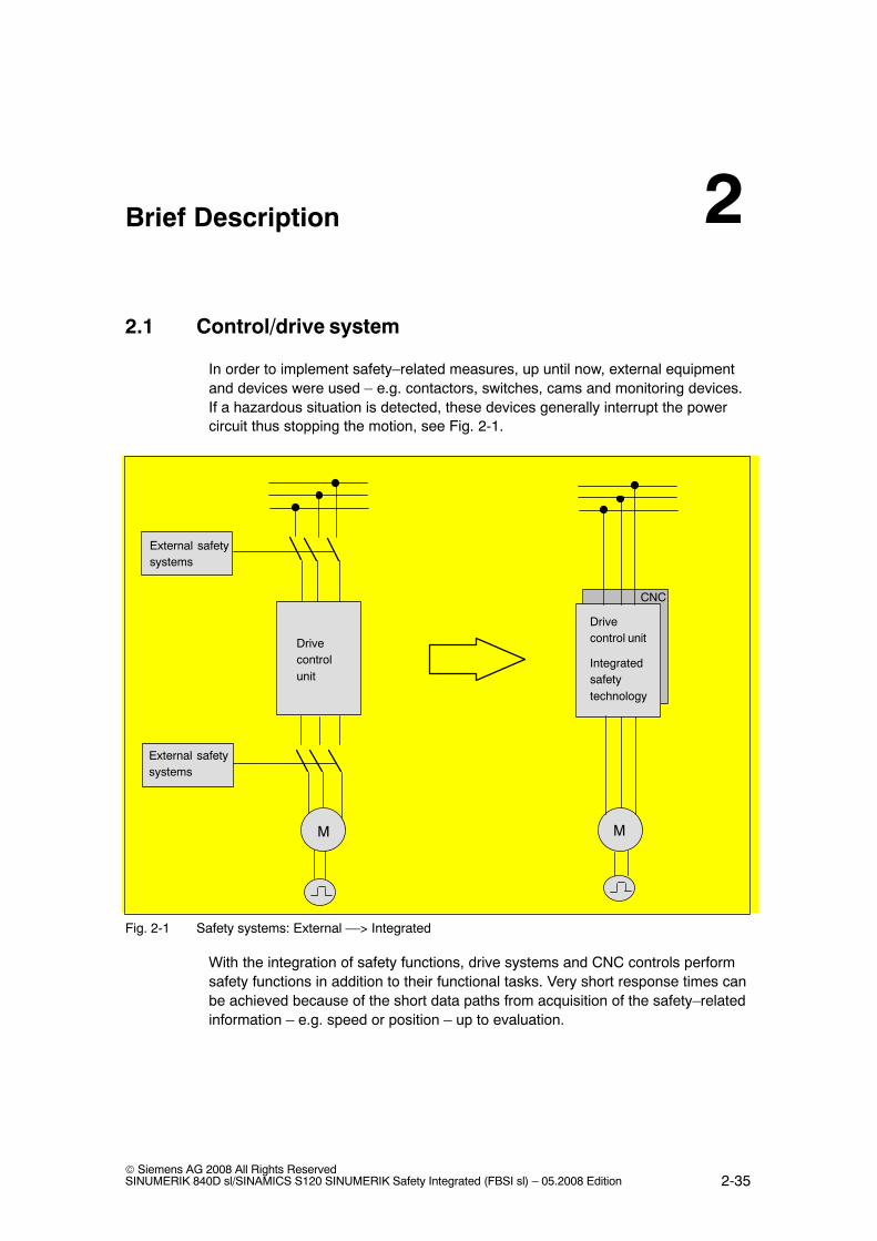
In order to implement safety–related measures, up until now, external equipmentand devices were used – e.g. contactors, switches, cams and monitoring devices.If a hazardous situation is detected, these devices generally interrupt the powercircuit thus stopping the motion, see Fig. 2-1.
Drivecontrol unit
Integratedsafetytechnology
Drivecontrolunit
MM
CNC
External safetysystems
External safetysystems
Fig. 2-1 Safety systems: External ––> Integrated
With the integration of safety functions, drive systems and CNC controls performsafety functions in addition to their functional tasks. Very short response times canbe achieved because of the short data paths from acquisition of the safety–relatedinformation – e.g. speed or position – up to evaluation.
2

Brief Description
2.1 Control/drive system
05.08
2-36© Siemens AG 2008 All Rights Reserved
SINUMERIK 840D sl/SINAMICS S120 SINUMERIK Safety Integrated (FBSI sl) – 05.2008 Edition
The systems with integrated safety technology generally respond very quicklywhen the permissible limit values are violated, e.g. position and velocity limit val-ues. They can be of decisive importance for the required monitoring result. Theintegrated safety technology can directly access the power semiconductors in thedrive controller without using electromechanical switching devices in the power cir-cuit. This helps reduce the susceptibility to faults – and the integration also reducesthe amount of cabling.
Brief Description
2.2 System integrated safety technology
05.08
2-37© Siemens AG 2008 All Rights ReservedSINUMERIK 840D sl/SINAMICS S120 SINUMERIK Safety Integrated (FBSI sl) – 05.2008 Edition
2.2 System integrated safety technology
SINUMERIK Safety Integrated
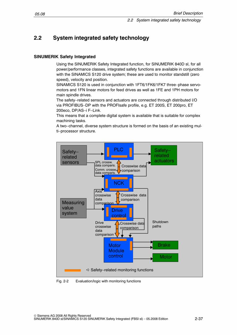
Using the SINUMERIK Safety Integrated function, for SINUMERIK 840D sl, for allpower/performance classes, integrated safety functions are available in conjunctionwith the SINAMICS S120 drive system; these are used to monitor standstill (zerospeed), velocity and position.SINAMICS S120 is used in conjunction with 1FT6/1FK6/1FK7 three–phase servo-motors and 1FN linear motors for feed drives as well as 1FE and 1PH motors formain spindle drives.The safety–related sensors and actuators are connected through distributed I/Ovia PROFIBUS–DP with the PROFIsafe profile, e.g. ET 200S, ET 200pro, ET200eco, DP/AS–i F–Link.This means that a complete digital system is available that is suitable for complexmachining tasks.A two–channel, diverse system structure is formed on the basis of an existing mul-ti–processor structure.
Shutdownpaths
Safety–relatedsensors
Safety–relatedactuators
Measuringvaluesystem
PLC
Drivecontrol
NCK
MotorModulecontrol
� Safety–related monitoring functions
Crosswise datacomparison
Crosswise datacomparison
Crosswise datacomparison
SPL crossw.data comparis.
Axiscrosswisedatacomparison
Drivecrosswisedatacomparison
Motor
Comm. crossw.data comparis.
Brake
Fig. 2-2 Evaluation/logic with monitoring functions

Brief Description
2.2 System integrated safety technology
05.08
2-38© Siemens AG 2008 All Rights Reserved
SINUMERIK 840D sl/SINAMICS S120 SINUMERIK Safety Integrated (FBSI sl) – 05.2008 Edition
Features of the two–channel, diverse structure
A two–channel, diverse structure is characterized by the following features:
� Two–channel structure with at least 2 independent computers (i.e. computerswith different hardware and software).
� Crosswise result and data comparison with forced checking procedure for thepurpose of detecting internal errors even in functions that are not often used(dormant errors).
� The computers can access data, reaction–free and decoupled at the shared(common) interfaces (e.g. actual value input).
Acquiring
The actual values of the individual axes are sensed by the sensor modules throughtwo channels and are provided to the drive and control.
In order to connect sensors and actuators in a safety–related fashion, their processsignals must be connected–in for further processing.
Analyzing
The safety–related functions are executed independently of one another by theNCK–CPU, PLC–CPU and the drive CPUs. The CPUs cyclically and mutuallycompare their safety–related data and results (crosswise data comparison). A testcan be carried out – initiated by the CPUs – to check the shutdown paths and ac-tuators (forced checking procedure).
Responding
When the integrated safety–related functions respond, the drive processors, thePLC processor and/or the NCK processor can act on the connected actuators in asafety–related fashion in–line with the actual situation. For example, the appropri-ate stop responses for the drives can be initiated and the actuators shutdown viathe shutdown paths.
2.2.1 Overview of the system–integrated safety functions
The safety–related functions are available in all of the operating modes and cancommunicate with the process via safety–related input/output signals. These canbe implemented individually for each axis.
� Safe stopping processWhen a monitoring function or a sensor responds (e.g. a light grid), the drivesare safely controlled down to standstill, optimally adapted to the actual oper-ating state of the machine.
Brief Description
2.2 System integrated safety technology
05.08
2-39© Siemens AG 2008 All Rights ReservedSINUMERIK 840D sl/SINAMICS S120 SINUMERIK Safety Integrated (FBSI sl) – 05.2008 Edition
� Safe acceleration monitoring (SBR)Monitors the speed characteristic. The speed must be reduced after a stop re-quest has been issued.
� Safe stop (SH)The drive pulses are cancelled. The energy feed is safely and electronically dis-connected.
� Safe operating stop (SBH)Monitors the drives during standstill (to ensure that they remain stationary). Thedrives remain fully functional in closed–loop control.
� Safely reduced speed (SG)Configured speed limits are monitored, e.g. when setting–up without using anagreement button.
� Safety–related output ”n<nx”This is used to detect the velocity range of a drive in a safety–related fashion.
� Safe software limit switches (SE)Variable traversing range limits
� Safety software cams and safety cam track (SN)To detect ranges
� Safety–related input/output signals (SGE/SGA)Interface to the process
� Safety–related communication via standard busDistributed I/Os for process and safety signals are connected via PROFIBUSusing the PROFIsafe profile.
� Safe programmable logic (SPL)All of the safe signals and internal logic are directly connected.
� Safe brake management (SBM)Safety–related two–channel brake control (SBC) and cyclic brake test (SBT).
� Integrated acceptance testPartially automated acceptance test for all safety–related functions. Simpleoperation of the test process, automatic configuration of Trace functions andautomatic generation of an acceptance report.
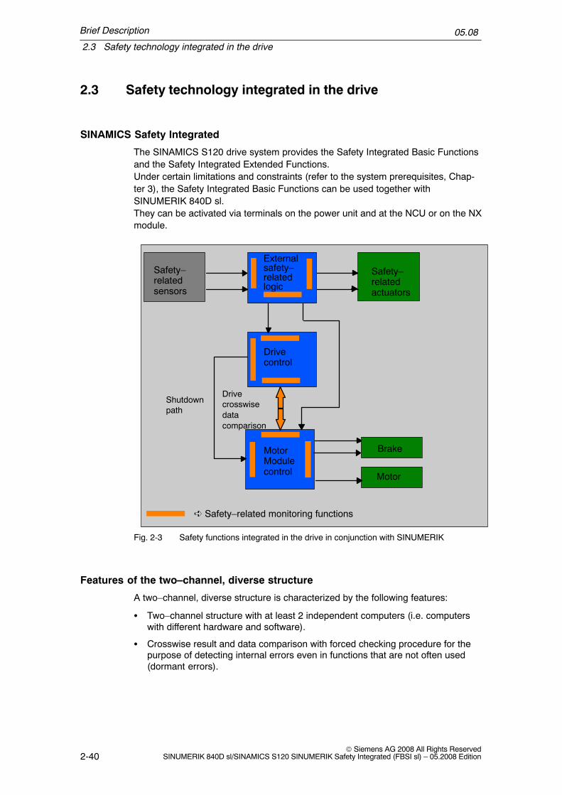
Brief Description
2.3 Safety technology integrated in the drive
05.08
2-40© Siemens AG 2008 All Rights Reserved
SINUMERIK 840D sl/SINAMICS S120 SINUMERIK Safety Integrated (FBSI sl) – 05.2008 Edition
2.3 Safety technology integrated in the drive
SINAMICS Safety Integrated
The SINAMICS S120 drive system provides the Safety Integrated Basic Functionsand the Safety Integrated Extended Functions.Under certain limitations and constraints (refer to the system prerequisites, Chap-ter 3), the Safety Integrated Basic Functions can be used together withSINUMERIK 840D sl.They can be activated via terminals on the power unit and at the NCU or on the NXmodule.
Shutdownpath
Safety–relatedsensors
Safety–relatedactuators
Externalsafety–relatedlogic
Drivecontrol
MotorModulecontrol
� Safety–related monitoring functions
Drivecrosswisedatacomparison
Motor
Brake
Fig. 2-3 Safety functions integrated in the drive in conjunction with SINUMERIK
Features of the two–channel, diverse structure
A two–channel, diverse structure is characterized by the following features:
� Two–channel structure with at least 2 independent computers (i.e. computerswith different hardware and software).
� Crosswise result and data comparison with forced checking procedure for thepurpose of detecting internal errors even in functions that are not often used(dormant errors).

Brief Description
2.3 Safety technology integrated in the drive
05.08
2-41© Siemens AG 2008 All Rights ReservedSINUMERIK 840D sl/SINAMICS S120 SINUMERIK Safety Integrated (FBSI sl) – 05.2008 Edition
Acquiring
In order to connect sensors and actuators in a safety–related fashion, their processsignals must be connected–in for further processing.
Analyzing
The two drive CPUs independently execute the safety–related functions. TheCPUs cyclically and mutually compare their safety–related data and results (cross-wise data comparison). A test can be carried out – initiated by the CPUs – to checkthe shutdown paths and actuators (forced checking procedure).
Responding
When the integrated safety–related functions respond, the drive processors canact on the connected actuators in a safety–related fashion in–line with the actualsituation. For example, the appropriate stop responses for the drives can be initi-ated and/or the brakes activated.
2.3.1 Overview of the safety functions integrated in the drive
The safety–related functions are available in all of the operating modes and cancommunicate with the process via safety–related input/output signals. These canbe implemented individually for each axis.
� Safe Torque Off (STO)The drive pulses are cancelled and therefore the energy feed is safely and elec-tronically disconnected
� Safe Brake Control (SBC)The brake is directly controlled at the Motor Module � through two channelsand monitored
� Safe Stop 1 (SS1)Braking along the OFF3 ramp, monitoring the stopping time and transition intoSTO

Brief Description
2.4 Comparison of the function names for SINUMERIK Safety Integrated and acc. to EN 61800–5–2
05.08
2-42© Siemens AG 2008 All Rights Reserved
SINUMERIK 840D sl/SINAMICS S120 SINUMERIK Safety Integrated (FBSI sl) – 05.2008 Edition
2.4 Comparison of the function names for SINUMERIKSafety Integrated and acc. to EN 61800–5–2
Function nameSINUMERIK Safety Integrated
Function name according to EN 61800–5–2
German English Abbr. German English Abbr.
Sicherer Halt(STOP A)
Safe standstill(STOP A)
SH Sicher abgeschal-tetes Moment
Safe torque off STO
STOP B STOP B – Sicherer Stop 1 Safe stop 1 SS1
STOP C STOP C – Sicherer Stop 2 Safe stop 2 SS2
STOP D STOP D – Sicherer Stop 2 Safe stop 2 SS2
STOP E STOP E – Sicherer Stop 2 Safe stop 2 SS2
Sicherer Stop 1 Safe stop 1 SS1 Sicherer Stop 1 Safe stop 1 SS1
Sichere Überwa-chung auf Besch-leunigung
Safe accelerationmonitor
SBR – – –
SichererBetriebshalt
Safe operatingstop
SBH SichererBetriebshalt
Safe operatingstop
SOS
Sicher reduzierteGeschwindigkeit
Safely reducedspeed
SG Sicher begrenzteGeschwindigkeit
Safely limitedspeed
SLS
SG–spezifischeSollwertbegren-zung
Safely reducedspeed – specificsetpoint limiting
– – – –
Sichere Software–Endschalter
Safe software limitswitch
SE Sicher begrenzteLage
Safely limitedposition
SLP
Sicheres Brem-senmanagement
Safe brakemanagement
SBM – – –
Sichere Bremsen-ansteuerung
Safe brake control SBC Sichere Bremsen-ansteuerung
Safe brake control SBC
Sicherer Brem-sentest
Safe brake test SBT – – –
Sichere Software–Nocken bzw.Nockenspur
Safe softwarecam, Safe camtrack
SN Safe cams Safe cams SCA
n < nx n < nx – Sichere Dreh-zahlüberwachung
Safe speedmonitor
SSM
Sicherheitsgerich-tete Ein–/Ausga-besignale
Safety–related I/O SGE/SGA
F–DI/F–DO
– – –
Sichere Program-mierbare Logik
Safe program-mable logic
SPL – – –
Sicheres SoftwareRelais
Safe softwarerelays
– – – –

3-43© Siemens AG 2008 All Rights ReservedSINUMERIK 840D sl/SINAMICS S120 SINUMERIK Safety Integrated (FBSI sl) – 05.2008 Edition
System Features
3.1 System requirements
� Software option ”SINUMERIK Safety Integrated”
SI–Basic (including 1 axis/spindle, up to 4 SPL I/Os) 6FC5800–0AM63–0YB0
SI–Comfort (including 1 axis/spindle, up to 64 SPL I/Os) 6FC5800–0AM64–0YB0
SI axis/spindle (in addition for each axis /spindle) 6FC5800–0AC70–0YB0
SI axis/spindle package (in addition, 15 axes/spindles) 6FC5800–0AC60–0YB0
� SINUMERIK 840D sl; software release:From 1.3.1 for safety functions integrated in the drive (SH/SBC via terminals,Chapter 4)From 1.3.2 for safety functions integrated in the system (Chapters 5 to 7)
!Warning
From SINAMICS SW2.5 onwards, the following applies:In a system configuration, the firmware versions of the DRIVE–CLiQ componentscan only differ from the versions on the CF card, if either
a) the automatic upgrade/downgrade (parameter p7826) is deactivated, orb) components with a new firmware version can no longer be downgraded to thestatus of the version available on the CF card.
Scenario a) is not permitted when Safety Integrated is used. The automaticupgrade/downgrade must not be disabled when Safety Integrated is used.(automatic firmware update (p7826) must be equal to 1)
Scenario b) is only permissible if this combination has been explicitly approved bythe manufacturer.
� SINUMERIK 840D sl; all NCU types can be used.
� The measuring circuit cables must comply with the specifications of the SINAM-ICS S120.
3

System Features
3.1 System requirements
05.08
3-44© Siemens AG 2008 All Rights Reserved
SINUMERIK 840D sl/SINAMICS S120 SINUMERIK Safety Integrated (FBSI sl) – 05.2008 Edition
� Safety–related devices/modules, that correspond to open–type devices accord-ing to UL 50, may only be operated in enclosure–type housings/cabinets thathave as a minimum degree of protection IP54 in accordance with EN 60529.Further, chassis units with degree of protection IP20 and IPXXB should beoperated corresponding to EN 60529 in higher–level enclosures.
� The state of a cleared safety–related input or output (i.e. the state logical ”0” ofan SGE/SGA and electrical ”low” of an associated I/O terminal) or the state of adrive where the pulses are cancelled that can be achieved by the user as wellby the fault response of the SINUMERIK Safety Integrated system, is definedas the so–called ”fail–safe state”. This is the reason that the system is only suit-able for applications where this state corresponds to the safe state of the pro-cess controlled by SINUMERIK Safety Integrated.
� Drives with slip cannot be used for SE and SN.
� The SINUMERIK Safety Integrated functions are only permissible in conjunctionwith the SINAMICS booksize units.
The following applies specifically for safety functions integrated in the drive:
� The Safety Integrated Extended Functions of SINAMICS cannot be used inconjunction with SINUMERIK.
� The Safety Integrated Basic Functions with chassis units can only be used ifSINUMERIK Safety Integrated is not used in the remaining drive group.
� A software option is not required when using the SINAMICS Safety IntegratedBasic Functions.
The following specifically applies for fail–safe SIMATIC modules:
� STEP7 F configuration tool (F Configuration Pack) as supplement to STEP7This F configuration tool is required so that ET 200 F modules or the DP/AS–iF–Link can be integrated into the HW configuration.The F configuration tool can be downloaded from the A&D Service&Supportpages under the Subject F–Configuration–Pack. Which F configuration toolcan be used for which STEP7 version is also specified there.
http://support.automation.siemens.com/WW/view/en/15208817
When using ET 200 F modules or DP/AS–i F–Link it should be noted that a versionof the F configuration tool should be used that the module already supports.Which modules can be configured with which versions that can be downloadedare also specified in the download area.
Note
Only the F–Configuration Pack is necessary to connect fail–safe SIMATICmodules to SINUMERIK. Neither SIMATIC S7 Distributed Safety nor SIMATIC S7F systems are required.

System Features
3.2 Latest information
05.08
3-45© Siemens AG 2008 All Rights ReservedSINUMERIK 840D sl/SINAMICS S120 SINUMERIK Safety Integrated (FBSI sl) – 05.2008 Edition
3.2 Latest information
Important note for maintaining the operational safety of your system.
!Warning
Systems with safety–related characteristics are subject to special operationalsafety requirements on the part of the operating company. The supplier is alsoobliged to comply with special product monitoring measures. For this reason, wepublish a special newsletter containing information on product developments andfeatures that are (or could be) relevant when operating safety–related systems.By subscribing to the appropriate newsletter, you will ensure that you are alwaysup–to–date and able to make changes to your system, when necessary.
Go into the Internet under:
http://www.automation.siemens.com
To subscribe to the newsletter, please proceed as follows:
Click on the menu item ”Support”. You can now open the Internet page for our”Service & Support” by clicking on the ”Service” menu item. By clicking on ”Sub-scribe to our newsletter now” on this page, you can open an additional window inwhich you can subscribe to the individual newsletter. Under the ”Product Support”heading on this page, you can see which newsletter is presently available. Pleaseopen the subject area/topic that is relevant for you. You will now be shown whichnewsletter is available for this particular subject area or topic. You can subscribe tothe corresponding newsletter by clicking on the box. If you require more detailedinformation on the newsletters then please click on these. A small supplementarywindow is opened from where you take the corresponding information.
Your subscription should cover the following product areas:
� SINUMERIK Safety Integrated
� SINAMICS Safety Integrated
� SIMATIC S7–300
� Distributed I/O
� SIMATIC software

System Features
3.3 Certification
05.08
3-46© Siemens AG 2008 All Rights Reserved
SINUMERIK 840D sl/SINAMICS S120 SINUMERIK Safety Integrated (FBSI sl) – 05.2008 Edition
3.3 Certification
The safety functions fulfill the requirements according to DIN EN 61508 for use upto and including SIL2 in an operating mode with a high requirement rate and Cate-gory 3 as well as PL d acc. to DIN EN ISO 13849–1. The average time up to ahazardous failure MTTFd and the probability of hazardous failures per hour PFHddepend on the degree of expansion of the system.
The ”Safe brake test” function complies with Category 2 acc. to DIN EN ISO13849–1.
The test certificates and test mark are listed in the Preface.The attachments to the test certificates with the certified software and hardwarereleases are not included in this documentation. If you require the appropriate at-tachments, then please use the address specified in the corrections/suggestionssheet (last page).
Additional information on the certification (test certification, PRÜFZERT mark) isprovided in the Preface.
3.4 Probability of failure
Please contact your local Siemens office on how to calculate PFH values.

System Features
3.5 Safety information & instructions and residual risks
05.08
3-47© Siemens AG 2008 All Rights ReservedSINUMERIK 840D sl/SINAMICS S120 SINUMERIK Safety Integrated (FBSI sl) – 05.2008 Edition
3.5 Safety information & instructions and residual risks
Note
There are additional safety information & instructions and residual risks in otherchapters, which are listed in the relevant locations in this documentation.
3.5.1 General residual risks for PDS (Power Drive Systems)
!Danger
The control and drive components for a power drive system (PDS) are allowed forindustrial and commercial use in industrial networks. Their use in public networksrequires a different configuration and/or additional measures.
These components may only be operated in closed enclosures or in higher–levelelectrical cabinets and when all of the protective devices and protected covers areused.
These components may only be handled by qualified and trained technicalpersonnel who are knowledgeable and observe all of the safety information andinstructions on the components and in the associated technical userdocumentation.
When carrying out a risk assessment of the machine in accordance with the ECMachinery Directive, the machine manufacturer must consider the followingresidual risks associated with the control and drive components of a Power DriveSystem.
1. Unintentional movements of driven machine components duringcommissioning, operation, maintenance, and repairs caused by, for example:
� Hardware defects and/or software errors in the sensors, controllers,actuators, and connection technology
� Response times of the controller and drive� Operating and/or ambient conditions not within the scope of the
specification� Parameterization, programming, cabling, and installation errors� Use of radio devices/cellular phones in the immediate vicinity of the
controller� External influence/damage
2. Exceptional temperatures as well as emissions of light, noise, particles, or gascaused by, for example:
� Component malfunctions� Software errors� Operating and/or ambient conditions not within the scope of the
specification� External influence/damage

System Features
3.5 Safety information & instructions and residual risks
05.08
3-48© Siemens AG 2008 All Rights Reserved
SINUMERIK 840D sl/SINAMICS S120 SINUMERIK Safety Integrated (FBSI sl) – 05.2008 Edition
!Danger
3. Hazardous touch voltages, e.g. as a result of:
� Component malfunctions� Influence of electrostatic charging� Induction of voltages in moving motors� Operating and/or ambient conditions not within the scope of the
specification� Condensation/conductive contamination� External influence/damage
4. Electrical, magnetic, and electromagnetic fields that can pose a risk to peoplewith a pacemaker and/or implants if they are too close.
5. Emission of pollutants if components or packaging are not disposed of properly.
An assessment of the residual risks of PDS components (see points 1 to 5 above)established that these risks do not exceed the specified limit values for thesecomponents. For more information about residual risks, refer to the relevantchapters in the technical user documentation.

System Features
3.5 Safety information & instructions and residual risks
05.08
3-49© Siemens AG 2008 All Rights ReservedSINUMERIK 840D sl/SINAMICS S120 SINUMERIK Safety Integrated (FBSI sl) – 05.2008 Edition
3.5.2 Additional safety information & instructions and residual risksfor Safety Integrated
!Danger
Risks associated with machines and plants can be reduced using SafetyIntegrated.Safe operation of the machine or plant with Safety Integrated is however onlypossible if the machine manufacturer
– precisely knows and observes this technical user documentation – including thedocumented limitations, safety information and residual risks;
– carefully executes the design and engineering of the machine or plant verifiedby qualified personnel that carefully perform and document an acceptance test;
– implements and validates all of the measures required, corresponding to therisk analysis of the machine or plant using the programmed and configuredfunctions of Safety Integrated or other appropriate resources.
Depending on the risk assessment of the machine or plant, the safety information& instructions and residual risks listed in this documentation must also beassigned, when required, to a hazardous level other than that specified in thisdocumentation.
The use of Safety Integrated does not replace the risk assessment of themachine or plant to be performed by the machine manufacturer as specifiedin the EC Machinery Directive.In addition to using Safety Integrated, additional measures are required tominimize risk.
Risk assessment enables the machine manufacturer to determine the residual riskfor his machine with respect to Safety Integrated. The following residual risks areknown.

System Features
3.5 Safety information & instructions and residual risks
05.08
3-50© Siemens AG 2008 All Rights Reserved
SINUMERIK 840D sl/SINAMICS S120 SINUMERIK Safety Integrated (FBSI sl) – 05.2008 Edition
!Warning
� Safety Integrated is only activated if all of the system components arepowered–up and have been booted.
� Faults in the absolute track (C–D track), cyclically interchanged phases ofmotor connections (V–W–U instead of U–V–W) and a reversal in the controldirection can cause an increase in the spindle speed or axis motion. Category 1and 2 Stop functions according to EN 60204–1 (defined as Stop B to E inSafety Integrated) that are provided are however not effective due to the fault.Category 0 stop function according to EN 60204–1 (defined as Stop A in SafetyIntegrated) is not activated until the transition or delay time set via machinedata has expired. When SBR is active, these errors are detected (STOP B/C)and the Category 0 stop function according to EN 60204–1 (STOP A in SafetyIntegrated) is activated as early as possible irrespective of this delay (seeChapter 6.4, ”Safe Acceleration Monitor”). Electrical faults (defectivecomponents etc.) can also result in the response described above.
� When incremental encoders are used, the functions ”safe software limitswitches” (SE) and ”safe software cams or cam tracks” (SN) can only be usedafter referencing has been successfully completed.
� When no user agreement has been given (see Chapter 5.4.4, ”Useragreement”), the safe software limit switches (SE) are not operative; the safesoftware cams or cam tracks (SN) are operative, but are not safe as defined bySafety Integrated.
� The simultaneous failure of two power transistors (one in the upper and theother offset in the lower inverter bridge) in the inverter may cause the axis tomove briefly.The maximum movement can be:Synchronous rotary motors: Max. movement = 180� / number of pole pairsSynchronous linear motors: Max. movement = pole widthExample: Synchronous motor:For a 6–pole synchronous motor, the axis can move by a maximum of 30degrees. With a ballscrew that is directly driven by, e.g. 20 mm per revolution,this corresponds to a maximum linear motion of approximately 1.6 mm.Example, synchronous linear motor:For a synchronous linear motor, the movement can be a maximum of one polewidth. This corresponds to the following distances:1FN1–07 27 mm1FN1–12/–18/–24 36 mm1FN3 20 mm

System Features
3.5 Safety information & instructions and residual risks
05.08
3-51© Siemens AG 2008 All Rights ReservedSINUMERIK 840D sl/SINAMICS S120 SINUMERIK Safety Integrated (FBSI sl) – 05.2008 Edition
!Warning
� The “Automatic restart” function of SINAMICS S120 must not be used inconjunction with safety functions since this is prohibited in Chapter 9.2.5.4.2 ofIEC 60204, Part 1 (1998). (Deselecting a safety shutdown function alone mustnot result in machine restarting.)
� For a 1–encoder system, encoder faults are detected by various HW and SWmonitoring functions. It is not permissible that these monitoring functions aredeactivated and they must be parameterized carefully. Depending on the faulttype and which monitor responds, a Category 0 or Category 1 stop functionaccording to EN 60204–1 (defined as STOP A or B in SINUMERIK SafetyIntegrated) is activated.
� The Category 0 stop function according to EN 60204–1 (defined as STOP A inSafety Integrated) means that the spindles/axes are not braked to zero speed,but coast to a stop (this may take an appropriately long time depending on thelevel of kinetic energy involved). This must be included in the protective doorlocking mechanism logic (e.g. with the logic operation n<nx.
� When a limit value is violated, the speed may exceed the set value briefly orthe axis/spindle may overshoot the setpoint position to a greater or lesserdegree during the period between error detection and system response. Thisdepends on the dynamic response of the drive and the parameters/machinedata settings that have been entered (see Chapter 6, ”System/drive integratedsafety functions”).
� A position–controlled axis may be forced out of the safe operating stop state(SBH) by mechanical forces that are greater than the max. axis torque. In suchcases, a stop function, Category 1 according to EN 60204–1 (STOP B) isactivated.
� Safety Integrated is not capable of detecting parameterization andprogramming errors made by the machine manufacturer. The required level ofsafety can only be assured by thorough and careful acceptance testing.
� Motor modules and motors must always be replaced with the same equipmenttype. If this is not the case, the parameters will no longer match the actualconfiguration – causing Safety Integrated to respond incorrectly. The axisinvolved must be re–commissioned if an encoder is replaced.
� If an internal or external fault occurs, none or only some of the parameterizedsafety functions are available during the STOP–F response triggered by thefault. This must be taken into account when a delay time between STOP F andSTOP B is parameterized. This is especially true for vertical axes.
� An additional residual risk is obtained as a result of the possible randomhardware faults for electronic systems, arising from their very principle, which isexpressed using this PFH value.

System Features
3.5 Safety information & instructions and residual risks
05.08
3-52© Siemens AG 2008 All Rights Reserved
SINUMERIK 840D sl/SINAMICS S120 SINUMERIK Safety Integrated (FBSI sl) – 05.2008 Edition
!Warning
� If, for a 1–encoder system,a) an individual electrical fault in the encoder, orb) an encoder shaft breakage (or the encoder shaft coupling slips) or theencoder housing becomes loosethe encoder signals remain at a steady–state (i.e. they no longer follow themotion, but have a correct signal level), then this fault is not detected when theaxis is stationary (e.g. in SBH). Generally, the axis is held by the activeclosed–loop control. Especially for vertical (suspended) axes, from aclosed–loop control–related perspective, it is conceivable that such an axiscould move downwards without this being detected. The risk described undera) of an electrical fault in the encoder is only possible for a few encoder typesdue to the principle of operation (e.g. encoders with microprocessor–controlledsignal generation, e.g. EQI from the Heidenhain company, HEAG 159/160 fromthe Hübner company, measuring systems from the AMO company with sin/cosoutput).All of the faults described above must be included in the risk analysis of themachine manufacturer. This analysis will indicate that for hanging/vertical axesor loads that drive the motor, additional protective measures are required, e.g.to exclude the fault under a):
� Use an encoder with analog signal generation or� Use a 2–encoder system
and to exclude the fault under b):
� Carry out an FMEA regarding encoder shaft breakage (or the encoder shaftcoupling slips) or if the encoder housing becomes loose and apply a faultexclusion process according to e.g. EN 61800–5–2 or
� Use a 2–encoder system (in this case it is not permissible that the encodersare mounted on same shaft).

4-53© Siemens AG 2008 All Rights ReservedSINUMERIK 840D sl/SINAMICS S120 SINUMERIK Safety Integrated (FBSI sl) – 05.2008 Edition
Safety Functions Integrated in the Drive
Note
This chapter describes the safety functions that are integrated in the drive – ”SafeTorque Off” (STO), ”Safe Brake Control” (SBC) and ”Safe Stop 1” (SS1), which arecontrolled via the drive terminals. The safety functions SH and SBC from thecontext of the safety–related motion monitoring functions are described in Chapter6 ”System/drive–integrated safety functions”. The SS1 safety function essentiallycorresponds there to STOP B. Control via terminals and from the motionmonitoring functions is in parallel and can be used independently of one another.
4.1 General information about SINAMICS Safety Integrated
4.1.1 Explanations and terminology
Note
In this chapter, the NCU/NX is designated as ”Control Unit”.
Two–channel monitoring structure
All the main hardware and software functions for Safety Integrated are imple-mented in two independent monitoring channels (e.g. shutdown signal paths, datamanagement, data comparison).
The two drive monitoring channels are implemented as follows:
� via the Control Unit
� via the Motor Module/Power Module belonging to a drive.
The monitoring functions in each monitoring channel work on the principle that adefined status must prevail before each action is carried out and a specificacknowledgement made after each action.
4

Safety Functions Integrated in the Drive
4.1 General information about SINAMICS Safety Integrated
05.08
4-54© Siemens AG 2008 All Rights Reserved
SINUMERIK 840D sl/SINAMICS S120 SINUMERIK Safety Integrated (FBSI sl) – 05.2008 Edition
If this expected response in a monitoring channel is not fulfilled, the drive coasts toa standstill (two channel) and an appropriate message is output.
Shutdown paths
Two independent switch–off signal paths are available. All switch–off signal pathsare low active, Thereby ensuring that the system is always switched to a safe sta-tus if a component fails or in the event of cable breakage.
If an error is discovered in the shutdown paths, the ”safe standstill” (Safe TorqueOff) function is activated and a system restart inhibited.
Monitoring cycle
The safety–related drive functions are executed cyclically in the monitoring cycle.
The safety monitoring clock cycle is a minimum of 4 ms. Increasing the basisDRIVE–CLiQ sampling time (p0110) also increases the safety monitoring clockcycle.
Parameter overview (refer to SINAMICS S List Manual)
� r9780 SI monitoring clock cycle (Control Unit)
� r9880 SI monitoring clock cycle (Motor Module)
Crosswise data comparison
A cyclic crosswise comparison of the safety–related data in the two monitoringchannels is carried out.
In the event of inconsistencies, the following occurs:
1. Fault F01611 or F30611 (STOP F) is output and the time in p9658 or p9858initiated.
2. Once the time has elapsed, a further fault (F01600 or F30600 (STOP A)) isoutput and the pulses are safely cancelled.
The stop response is transferred to the other monitoring channel so that two–chan-nel stopping can be carried out.
Detailed information on the stop responses, see Chapter 6.3 ”Safe Stops A–F”.

Safety Functions Integrated in the Drive
4.1 General information about SINAMICS Safety Integrated
05.08
4-55© Siemens AG 2008 All Rights ReservedSINUMERIK 840D sl/SINAMICS S120 SINUMERIK Safety Integrated (FBSI sl) – 05.2008 Edition
4.1.2 Supported functions
The following Safety Integrated functions (SI functions) are in conformance withEN 61800–5–2:
� Safety Integrated basic functions
These functions are part of the standard scope of the drive.
– Safe Torque Off (STO)STO is a safety function that prevents the drive from restarting unexpect-edly, in accordance with EN 60204–1, Section 5.4.
Note
When a drive object that has Safety Integrated functions released is switched to”Parking” mode, the Safety Integrated software responds by activating STOwithout generating a separate message.
– Safe Stop 1 (SS1, time–controlled)The SS1 function is based on the “Safe Torque Off” function. This meansthat a Category 1 stop in accordance with EN 60204–1 can be implemented.
– Safe Brake Control (SBC)The SBC function permits the safe control of a holding brake.SBC is not supported by chassis components.
4.1.3 Parameter, checksum, version, password
Properties of Safety Integrated parameters
The following applies to Safety Integrated parameters:
� They are kept separate for each monitoring channel.
� During startup, a checksum (Cyclic Redundancy Check, CRC) over the safetyparameters is generated and checked. The display parameters are notcontained in the CRC.
� Data storage: The parameters are stored on the non–volatile CompactFlashcard.
� Establish/restore the factory setting for safety parametersYou can only reset the safety parameters to the factory setting on adrive–specific basis using p0970 or p3900 when the safety functions are notenabled (p9601 = p9801 = 0).
All the factory settings can be restored (p0976 = 1 and p0009 = 30 on the Con-trol Unit) even when the safety functions are enabled (p9601 = p9801 � 0).
� They are password–protected against accidental or unauthorized changes.

Safety Functions Integrated in the Drive
4.1 General information about SINAMICS Safety Integrated
05.08
4-56© Siemens AG 2008 All Rights Reserved
SINUMERIK 840D sl/SINAMICS S120 SINUMERIK Safety Integrated (FBSI sl) – 05.2008 Edition
Checking the checksum
For each monitoring channel, the safety parameters include one parameter for theactual checksum for the safety parameters that have undergone a checksumcheck.
During commissioning, the actual checksum must be transferred in the corre-sponding parameters of the specified reference checksum. This can be done for allchecksums of a drive object at the same time with parameter p9701.
Basic functions
� r9798 SI actual checksum SI parameters (Control Unit)
� p9799 SI reference checksum SI parameters (Control Unit)
� r9898 SI actual checksum SI parameters (Motor Module)
� p9899 SI reference checksum SI parameters (Motor Module)
Each time the system boots, the actual checksum is calculated using the safetyparameters and then compared with the specified reference checksum.
If the actual and specified reference checksums are different, fault F01650 orF30650 is output and an acceptance test requested.
Safety Integrated versions
The safety software versions on the Control Units and on the Motor Modules havetheir own version ID.
For the basic functions:
� r9770 SI version, drive–autonomous safety functions (Control Unit)
� r9870 SI version (Motor Module)
!Warning
From SINAMICS SW2.5 onwards, the following applies:In a system configuration, the firmware versions of the DRIVE–CLiQ componentscan only differ from the versions on the CF card, if either
a) the automatic upgrade/downgrade (parameter p7826) is deactivated, orb) components with a new firmware version can no longer be downgraded to thestatus of the version available on the CF card.
Scenario a) is not permitted when Safety Integrated is used. The automaticupgrade/downgrade must not be disabled when Safety Integrated is used.(automatic firmware update (p7826) must be equal to 1)
Scenario b) is only permissible if this combination has been explicitly approved bythe manufacturer.
Safety Functions Integrated in the Drive
4.1 General information about SINAMICS Safety Integrated
05.08
4-57© Siemens AG 2008 All Rights ReservedSINUMERIK 840D sl/SINAMICS S120 SINUMERIK Safety Integrated (FBSI sl) – 05.2008 Edition
Password
Note
A password allocation is not relevant in the SINUMERIK environment. It is onlyused in conjunction with Starter (commissioning tool used for SINAMICS).
The safety password protects the safety parameters against unauthorized writeaccess.
In commissioning mode for Safety Integrated (p0010 = 95), you cannot changesafety parameters until you have entered the valid safety password in p9761 forthe drives.
� When Safety Integrated is commissioned for the first time, the following applies:
– Safety password = 0
– Default setting for p9761 = 0
This means:
The safety password does not need to be set during initial commissioning.
� Change password for the drives
– p0010 = 95 commissioning mode (refer to Chapter 4.6 ”Commissioning thefunctions STO, SBC and SS1”)
– p9761 = Enter ”old safety password”
– p9762 = Enter ”new password”
– p9763 = Confirm ”new password”
– The new and confirmed safety password is valid immediately.
If you need to change safety parameters but you do not know the safety password,proceed as follows:
1. Restore the factory setting of the complete drive unit (Control Unit with allconnected drives/components) (see SINUMERIK 840D sl/SINAMICS S120Commissioning Manual).
2. Recommission the drive unit and drives
3. Recommission Safety Integrated
Parameter overview (see Chapter 8.2.2 ”Description of the parameters”)
� p9761 Enter SI password
� p9762 New SI password
� p9763 Confirm SI password

Safety Functions Integrated in the Drive
4.1 General information about SINAMICS Safety Integrated
05.08
4-58© Siemens AG 2008 All Rights Reserved
SINUMERIK 840D sl/SINAMICS S120 SINUMERIK Safety Integrated (FBSI sl) – 05.2008 Edition
4.1.4 Forced checking procedure
Forced checking procedure and test of the shutdown paths
The forced checking procedure function at the switch–off signal paths is used todetect software/hardware faults at both monitoring channels in time and is auto-mated by means of activation/deactivation of the ”Safe Torque Off” function.
To fulfill the requirements of EN 954–1 regarding timely error detection, the twoshutdown paths must be tested at least once within a defined time to ensure thatthey are functioning properly. For this purpose, the forced checking proceduremust be either initiated manually by the user or automatically as part of the pro-cess.
A timer ensures that the forced checking procedure is carried out as quickly aspossible.
� p9659 SI timer for the forced checking procedure
The forced checking procedure of the shutdown paths must be carried out at leastonce during the time set in this parameter.
After this time has expired, an appropriate alarm is issued (A01699 ”SI CU: Theshutdown paths must be tested”) and remains until the forced checking procedurehas been performed.
The timer is reset to the selected value each time the STO function is deactivated.
When the appropriate safety devices are implemented (e.g. protective doors), itcan be assumed that running machinery will not pose any risk to personnel. Forthis reason, only an alarm is output to inform the user that a forced checking pro-cedure is due and request that this be carried out at the next available opportunity.This alarm does not affect machine operation.
The user must set the time interval for carrying out the forced checking procedureto between 0.00 and 9000.00 hours depending on the application (factory setting:8.00 hours).
The 9000 hours are only applicable for STO, SBC, SS1 functions that are integra-ted in the drive and controlled via local terminals.
When using the safety–related motion monitoring functions according to Chapter 6,the value should be set to 9000 hours so that the alarm to carry out the forcedchecking procedure is no longer output. After carrying out the forced checking pro-cedure from STO, the forced checking procedure timer is also re–started by themotion monitoring functions.
Examples for carrying out the forced checking procedure:
� When the drives are at a standstill after the system has been powered–up.
� When the protective door is opened.
� In defined cycles (e.g. every 8 hours).
� In the automatic mode (time and event dependent).

Safety Functions Integrated in the Drive
4.2 Safe Torque Off (STO)
05.08
4-59© Siemens AG 2008 All Rights ReservedSINUMERIK 840D sl/SINAMICS S120 SINUMERIK Safety Integrated (FBSI sl) – 05.2008 Edition
4.2 Safe Torque Off (STO)
General description
In conjunction with a machine function or in the event of a fault, the ”Safe TorqueOff (STO)” function is used to safely disconnect the torque–generating motorpower supply.
When the function is selected, the drive unit is in a ”safe status”. The closing lock-out function prevents the drive unit from being restarted.
The two–channel pulse cancellation integrated in the Motor Modules is the basisfor this function.
Functional features of Safe Torque Off
� This function is integrated in the drive, i.e. a higher–level control is not required.
� The function is drive specific. This means that each drive has the function and itmust be individually commissioned.
� The function must be enabled via parameter.
� When the Safe Torque Off function is selected:
– The motor cannot be started accidentally.
– The safety–related pulse cancellation interrupts the torque–generatingpower–feed to the motor.
– The power unit and motor are not electrically isolated.
!Warning
Appropriate measures must be taken to ensure that the motor does not moveonce the motor power supply has been disconnected (”coast down”) (e.g. enablethe ”Safe brake control” function for a vertical axis).
!Warning
If two power transistors in the Motor Module (one in the upper and one in the lowerbridge) fail at the same time, this can cause a momentary movement.
The maximum movement can be:
� Synchronous rotary motors: Max. movement = 180° / number of pole pairs� Synchronous linear motors: Max. movement = pole width
� The status of the Safe Torque Off function is displayed using parameters.

Safety Functions Integrated in the Drive
4.2 Safe Torque Off (STO)
05.08
4-60© Siemens AG 2008 All Rights Reserved
SINUMERIK 840D sl/SINAMICS S120 SINUMERIK Safety Integrated (FBSI sl) – 05.2008 Edition
Enabling the Safe Torque Off function
The Safe Torque Off function is enabled via the following parameters:
� STO via terminals:
– p9601.0 = 1, p9801.0 = 1
Selecting/deselecting ”Safe Torque Off”
The following occurs when Safe Torque Off is selected:
� Every monitoring channel initiates safety–related pulse cancellation via its shut-down path.
� A motor holding brake (if connected and configured) is closed.
The following occurs when Safe Torque Off is deselected:
� Every monitoring channel withdraws (cancels) the safety–related pulse can-cellation via its shutdown path.
� The safety prompt ”Apply motor holding brake” is canceled.
� Any pending STOP F or STOP A commands are canceled.
Note
If the Safe Torque Off function is deselected and selected again through onechannel within the time in p9650/p9850, the pulses are canceled but a signal is notoutput.
If you want a message to be displayed in this case, however, you must reconfigureN001620/N30620 via p2118 and p2119 as an alarm or fault.
Restart after the Safe Torque Off function has been selected
1. Deselect the function in each monitoring channel via the input terminals.
2. Issue drive enable signals.
3. Cancel the power–on inhibit and power–up again.
4. Move/traverse the drives again.
Status for Safe Torque Off
The status of the Safe Torque Off function is displayed using the following parameters:
� r9772 CO/BO: SI status (Control Unit)
� r9872 CO/BO: SI status (Motor Module)
� r9773 CO/BO: SI status (Control Unit + Motor Module)
� 9774 CO/BO: SI Status (Safe Torque Off group)

Safety Functions Integrated in the Drive
4.3 Safe Stop 1 (SS1, time–controlled)
05.08
4-61© Siemens AG 2008 All Rights ReservedSINUMERIK 840D sl/SINAMICS S120 SINUMERIK Safety Integrated (FBSI sl) – 05.2008 Edition
Response times for the Safe Torque Off function
The following values can be specified for the response times when the function isselected/deselected via the input terminals:
� Typical response time
2 x safety monitoring cycle CU (r9780) + inputs/outputs sampling time (p0799)
� Maximum response time that can occur when an error develops:
4 x safety monitoring cycle CU (r9780) + input/output time sampling time(p0799)
4.3 Safe Stop 1 (SS1, time–controlled)
General description
The Safe Stop 1 function can be used to stop the drive in accordance with EN60204–1, Stop Category 1. After ”Safe Stop 1” has been selected, the drive brakesalong the OFF3 ramp (p1135), and after the delay time set in p9652/p9852,switches the pulses into the Safe Torque Off (STO) state.
!Caution
When the SS1 (time–controlled) function has been activated through theparameterization of a delay in p9652/p9852, it is no longer possible to select STOvia terminals.
Functional features of Safe Stop 1
� SS1 is activated by p9652 and p9852 (delay time) not equal to ”0”.
� The function can only be activated in conjunction with Safe Torque Off.
� When SS1 is selected, the drive is braked along the OFF3 ramp (p1135) andSTO/SBC are automatically initiated after expiry of the delay time (p9652/9852).
After the function has been activated the delay time runs – even if the functionis deselected during this time. In this case, after the delay time has expired, theSTO/SBC function is selected and then again deselected immediately.
� The selection is realized through two channels – however braking along theOFF3 ramp, only through one channel.
Enabling the SS1 function
The function is enabled by entering the delay time in p9652 and p9852.

Safety Functions Integrated in the Drive
4.3 Safe Stop 1 (SS1, time–controlled)
05.08
4-62© Siemens AG 2008 All Rights Reserved
SINUMERIK 840D sl/SINAMICS S120 SINUMERIK Safety Integrated (FBSI sl) – 05.2008 Edition
Prerequisite
The Safe Torque Off function must be enabled.
In order that the drive can brake down to a standstill even when selected throughone channel, the time in p9652/p9852 must be shorter than the sum of the timesfrom the parameters for the crosswise data comparison (p9650/p9850 andp9658/9858).
The time in p9652/p9852 must be dimensioned so that after selection, the drivebrakes down to a standstill.
Status for Safe Stop 1
The status of the Safe Stop 1 function is displayed using the following parameters:
� r9772 CO/BO: SI status (Control Unit)
� r9773 CO/BO: SI status (Control Unit + Motor Module)
� r9774 CO/BO: SI status (safe standstill group)
� r9872 CO/BO: SI status (Motor Module)
Alternatively, the status of the functions can be displayed using the configurablemessages N01621 and N30621 (configured using p2118 and p2119).
Overview, important parameters (see Chapter 8.2.2 ”Description of parameters”)
� refer to the safe standstill function
� p1135 OFF3 ramp–down time
� p9652 SI Safe Stop 1 delay time (Control Unit)
� p9852 SI Safe Stop 1 delay time (Motor Module)
Safety Functions Integrated in the Drive
4.4 Safe Brake Control (SBC)
05.08
4-63© Siemens AG 2008 All Rights ReservedSINUMERIK 840D sl/SINAMICS S120 SINUMERIK Safety Integrated (FBSI sl) – 05.2008 Edition
4.4 Safe Brake Control (SBC)
Description
Safe Brake Control is used to control actuators that function according to theclosed–circuit principle (e.g. brake).
!Warning
The Safe Brake Control function does not detect faults in the brake itself – such ase.g. brake winding short–circuit, worn brakes and similar.
If a cable breaks, this is only recognized by the Safe Brake Control function whenthe status changes, i.e. when the brake is applied/released.
Functional features of Safe Brake Control (SBC)
� When Safe Torque Off is selected or when safety monitors are triggered, ”SBC”is performed with safe pulse cancelation.
� Unlike conventional brake control, SBC is implemented via p1215 through twochannels.
� SBC is initiated independently of the brake control mode set in p1215. However,SBC is not recommended for p1215 = 0 or 3.
� The function must be enabled via parameter.
� Each time Safe Torque Off is selected, the holding brake is applied immediatelywith a forced checking procedure carried out.
Enabling the Safe Brake Control (SBC) function
The Safe Brake Control function is enabled via the following parameters:
� p9602 ”SI enable safe brake control (Control Unit)”
� p9802 ”SI enable safe brake control (Motor Module)”
The Safe Brake Control function only becomes active if at least one safety monitor-ing function is enabled (i.e. p9601 = p9801 � 0).

Safety Functions Integrated in the Drive
4.4 Safe Brake Control (SBC)
05.08
4-64© Siemens AG 2008 All Rights Reserved
SINUMERIK 840D sl/SINAMICS S120 SINUMERIK Safety Integrated (FBSI sl) – 05.2008 Edition
Two–channel brake control
The brake is controlled from the Control Unit. The brake can be closed through twosignal paths.
Motor ModuleNCU 7x0
TB+
TB–
P24
Motor
Closed–circuit brake
Brake diagnostics
MMBR2
DRIVE–CLiQ
BR1
BR+
BR–
Gating
Control terminal 2
terminal 1
Fig. 4-1 Two–channel brake control, booksize
The Motor Module carries out a check to ensure that the Safe Brake Control func-tion is working properly and ensures that, if the Control Unit fails or is faulty, thebrake current is interrupted and the brake applied.
The brake diagnosis can only reliably detect a malfunction in either of the switches(TB+, TB–) when the status changes (when the brake is released or applied).
If the Motor Module or Control Unit detects a fault, the brake current is switched offand the safe status is reached.
Response time with the Safe Brake Control function
The following values can be specified for the response times when the function isselected/deselected via input terminals:
� Typical response time4x safety monitoring clock cycle CU (r9780) + inputs/outputs, sampling time(p0799)
� Maximum response time that can occur when an error develops8x safety monitoring clock cycle CU (r9780) + inputs/outputs, sampling time(p0799)

Safety Functions Integrated in the Drive
4.5 Control via terminals on the Control Unit and the power unit
05.08
4-65© Siemens AG 2008 All Rights ReservedSINUMERIK 840D sl/SINAMICS S120 SINUMERIK Safety Integrated (FBSI sl) – 05.2008 Edition
Example:
AssumptionSafety monitoring clock cycle CU (r9780) = 4 ms andInputs/outputs sampling time (r0799) = 4 ms
tR_type = 4x r9780 (4 ms) + r0799 (4 ms) = 20 mstR_max = 8x r9780 (4 ms) + r0799 (4 ms) = 36 ms
Parameter overview (see Chapter 8.2.1 ”Overview of parameters”)
� p0799 ”CU inputs/outputs, sampling time”
� r9780 ”SI monitoring clock cycle (Control Unit)”
� r9880 ”SI monitoring clock cycle (Motor Module)”
4.5 Control via terminals on the Control Unit and the power unit
Features
� Only for the STO, SS1 (time–controlled) and SBC functions
� Dual–channel structure via two digital inputs (Control Unit/power unit)
� Input filter for test signals with a dark period of less than 1 ms
� Different terminal strips depending on design
� Automatic ANDing of up to 8 digital inputs (p9620[0...7]) on the Control Unitwith parallel configuration of power units in chassis format.
Terminals for STO, SS1 (time–controlled), SBC
The functions are separately selected/deselected for each drive using two terminals.
� 1. Control Unit shutdown pathThe required input terminal for Safe Torque Off (STO) is selected via the BICOinterconnection (BI: p9620[0]).Digital input DI 0 ... DI 7 on the Control Unit can be used as a signal source(NCU). NX modules have DI 0 to DI 3.
� 2. Motor Module shutdown pathThe input terminal is the ”EP” (”Enable Pulses”) terminal.
Both terminals must be simultaneously energized, otherwise a fault will be issued.

Safety Functions Integrated in the Drive
4.5 Control via terminals on the Control Unit and the power unit
05.08
4-66© Siemens AG 2008 All Rights Reserved
SINUMERIK 840D sl/SINAMICS S120 SINUMERIK Safety Integrated (FBSI sl) – 05.2008 Edition
r0722.x
NCU 7x0
DRIVE–CLiQ
Temp+
X21/X22
Temp–
EP M
EP +24 V
U2V2
BR+
W2
BR–
DI x
M
BI:p9620
Motor Module
DRIVE–CLiQ DRIVE–CLiQ
NCU X122.4
Monitoring channelMotor Module
~M3
G
Monitoring channelControl Unit
4
3
2
1
Fig. 4-2 Terminals for ”Safe Torque Off”: example for Motor Modules, booksize format
Grouping drives
If the function is to be simultaneously initiated for several drives, the terminals forthe corresponding drives must be grouped together:
� 1st Control Unit shutdown pathBy appropriately interconnecting the binector input to a joint input terminal forthe drives to be combined to form a group.
� 2nd Motor Module shutdown pathBy appropriately connecting terminal ”EP” for the individual Motor Modules be-longing to a group.
Note
The grouping must be identical in both monitoring channels.
If a fault in a drive results in a Safe Torque Off (STO), this does not automaticallymean that the other drives in the same group also switch to Safe Torque Off(STO).
The assignment is checked while testing the shutdown paths. The operator selectsSafe Torque Off for each group. The check is drive–specific.

Safety Functions Integrated in the Drive
4.5 Control via terminals on the Control Unit and the power unit
05.08
4-67© Siemens AG 2008 All Rights ReservedSINUMERIK 840D sl/SINAMICS S120 SINUMERIK Safety Integrated (FBSI sl) – 05.2008 Edition
Example: Terminal groups
It must be possible to select/deselect the Safe Torque Off function separately forgroup 1 (drive 1 and 2) and group 2 (drive 3 and 4).
In addition, the same grouping for safe standstill must be assigned on both theControl Unit and the Motor Modules.
r0722.
NCU7x0EP
M
SingleMotor
Module
DoubleMotor
Module
SingleMotor
Module
Group 1 Group 2
EP EP EP
Selecting/deselectingGroup 1
Selecting/
Group 2
r0722.
M
Drive 1p9620
Drive 2p9620
Drive 3p9620
Drive 4p9620
M M M
Drive1
Drive2 3
Drive4
M
LineModule
X132.3
X132.4
DI6
DI7
desekecting
Fig. 4-3 Example: Terminal groups for Motor Modules, booksize format
Information on the parallel connection of Motor Modules in chassis format
When Motor Modules in chassis format are connected in parallel, a safe AND ele-ment is created on the parallel drive object. The number of indexes in p9620 corre-sponds to the number of parallel chassis components in p0120.
Safety Functions Integrated in the Drive
4.5 Control via terminals on the Control Unit and the power unit
05.08
4-68© Siemens AG 2008 All Rights Reserved
SINUMERIK 840D sl/SINAMICS S120 SINUMERIK Safety Integrated (FBSI sl) – 05.2008 Edition
Simultaneity and tolerance time of the two monitoring channels
The functions must be selected/deselected simultaneously in both monitoringchannels using the input terminals and act only on the associated drive.
1 signal: Deselecting the function
0 signal: Selecting the function
”Simultaneously” means:
The changeover must be completed in both monitoring channels within the para-meterized tolerance time.
� p9650 SI tolerance time F–DI changeover (Control Unit)
� p9850 SI tolerance time F–DI changeover (Motor Module)
If the function is not selected/deselected within the tolerance time, this is detectedby the crosswise data comparison and fault F01611 and F30611 (STOP F) is out-put. In this case, the pulses have already been canceled as a result of the selec-tion through one channel.

Safety Functions Integrated in the Drive
4.6 Commissioning the STO, SBC and SS1 functions
05.08
4-69© Siemens AG 2008 All Rights ReservedSINUMERIK 840D sl/SINAMICS S120 SINUMERIK Safety Integrated (FBSI sl) – 05.2008 Edition
4.6 Commissioning the STO, SBC and SS1 functions
4.6.1 General information about commissioning safety functions
Note
� The ”STO”, ”SBC” and ”SS1” functions are drive specific, which means that thefunctions must be commissioned individually for each drive.
� To support the ”STO” and ”SBC” functions, the following (minimum) safetyversions are required:
Control Unit: V02.01.01 (r9770[0...2])
Motor Module: V02.01.01 (r9870[0...2])
� To support the SS1 function, the following (minimum) safety version is required:
Control Unit: V02.04.01 (r9770[0...2])
Motor Module: V02.04.01 (r9870[0...2])
� If the version in the Motor Module is incompatible, the Control Unit responds asfollows during the switchover to safety commissioning mode (p0010 = 95):
– Fault F01655 (SI CU: Align the monitoring functions) is output. The faultinitiates stop response OFF2.
The fault cannot be acknowledged until the safety commissioning mode(p0010 � 95) is exited.
– The Control Unit initiates a safe pulse cancellation via its own safetyshutdown path.
– If parameterized (p1215), the brake is closed.
– It is not possible to enable the safety functions (p9601/p9801 andp9602/p9802).
Prerequisites for commissioning the safety functions
1. Commissioning of the drives must be completed.
2. The non safety–related pulse cancellation must be present,e.g. via OFF1 = ”0” or OFF2 = ”0”
If a brake is connected and has been parameterized, then the brake is closed.
3. The terminals for ”Safe Torque Off” must be wired.
– Control Unit: Digital input DI 0 ... DI 7 (NCU)Digital input DI 0 ... DI 3 (NX)
– Motor Module: Terminal ”EP”
4. For operation with SBC, the following applies:
A brake must be connected to the appropriate Motor Module connector.

Safety Functions Integrated in the Drive
4.6 Commissioning the STO, SBC and SS1 functions
05.08
4-70© Siemens AG 2008 All Rights Reserved
SINUMERIK 840D sl/SINAMICS S120 SINUMERIK Safety Integrated (FBSI sl) – 05.2008 Edition
4.6.2 Procedure for commissioning STO, SBC and SS1
In the SINUMERIK environment, commissioning can be simplified by using thesoftkeys ”Activate drive commissioning” and ”Deactivate drive commissioning”.
With ”Activate drive commissioning”, p0010 is set to 95; the required functions canthen be enabled and the settings entered (also refer to Table 4-1 ”CommissioningSTO, SBC and SS1, Steps 3 to 9).
With ”Deactivate drive commissioning” the checksums (p9799 = r9798, p9899 =r9898) are set to the same value and p0010 is set to 0.
To commission the STO, SBC and SS1 functions, carry out the following steps:
Table 4-1 Commissioning the ”STO”, ”SBC” and ”SS1” functions
No. Parameter Description and comments
1 p0010 = 95 Sets the Safety Integrated commissioning mode
� The following alarms and faults are output:
– A01698 (SI CU: Commissioning mode active)
Only when commissioning the system for the first time:
– F01650 (SI CU: Acceptance test required) with fault value = 130 (nosafety parameters exist for the Motor Module).
– F30650 (SI MM: Acceptance test required) with fault value = 130 (nosafety parameters exist for the Motor Module).
For information on the acceptance test and acceptance report, seestep 4.
� The pulses are safely cancelled and monitored by the Control Unit andMotor Module.
� The safety sign–of–life is monitored by the Control Unit and Motor Module.
� The function for exchanging stop responses between the control unit andmotor module is active.
� An existing and parameterized brake has already been closed.
� In this mode, fault F01650 or F30650 with fault value = 2003 is output aftera safety parameter is changed for the first time.
This behavior applies for the entire duration of safety commissioning, whichmeans that the STO function cannot be selected/deselected while safetycommissioning mode is active because this would constantly force safe pulsecancellation.

Safety Functions Integrated in the Drive
4.6 Commissioning the STO, SBC and SS1 functions
05.08
4-71© Siemens AG 2008 All Rights ReservedSINUMERIK 840D sl/SINAMICS S120 SINUMERIK Safety Integrated (FBSI sl) – 05.2008 Edition
Table 4-1 Commissioning the ”STO”, ”SBC” and ”SS1” functions, continued
No. Description and commentsParameter
2 p9761 = ”Value” Sets the safety password
When Safety Integrated is commissioned for the first time, the following applies:
� Safety password = 0
� Default setting for p9761 = 0
This means that the safety password does not need to be set during initialcommissioning.
3
p9601.0
p9801.0
Enable Safe Torque Off function
STO via Control Unit terminals
STO via Motor Module terminals
� The parameters are not changed until safety commissioning mode hasbeen exited (i.e. when p0010 � 95 is set).
� Both parameters are included in the crosswise data comparison and must,therefore, be identical.
4
p9602 = 1
p9802 = 1
Enables the safe brake control function
Enables SBC on the Control Unit
Enables SBC on the Motor Module
� The parameters are not changed until safety commissioning mode hasbeen exited (i.e. when p0010 � 95 is set).
� Both parameters are included in the crosswise data comparison and must,therefore, be identical.
� The safe brake control function only becomes active if at least one safetymonitoring function is enabled (i.e. p9601 = p9801 � 0).
5
p9652 > 0
p9852 > 0
Enable Safe Stop 1 function
Enable SS1 on the Control Unit
Enable SS1 on the Motor Module
� The parameters are not changed until safety commissioning mode hasbeen exited (i.e. when p0010 � 95 is set).
� Both parameters are included in the crosswise data comparison and must,therefore, be identical.
� The Safe Stop 1 function only becomes active if at least one safety monitor-ing function is enabled (i.e. p9601 = p9801 � 0).

Safety Functions Integrated in the Drive
4.6 Commissioning the STO, SBC and SS1 functions
05.08
4-72© Siemens AG 2008 All Rights Reserved
SINUMERIK 840D sl/SINAMICS S120 SINUMERIK Safety Integrated (FBSI sl) – 05.2008 Edition
Table 4-1 Commissioning the ”STO”, ”SBC” and ”SS1” functions, continued
No. Description and commentsParameter
6
p9620 = ”Value”
Terminal ”EP”
Set terminals for Safe Torque Off (STO)
Set the signal source for STO on the Control Unit
Connects terminal ”EP” (Enable Pulses) on the Motor Module.
� Control Unit monitoring channel:
By appropriately interconnecting BI: p9620 for the individual drives, the fol-lowing is possible:
– Selecting/deselecting the STO
– the terminals for safe standstill can be grouped
Digital input DI 0 ... DI 7 on the Control Unit can be used as a signal source(NCU). DI 0 ... DI 3 (NX).
� Motor Module monitoring channel:
By wiring the ”EP” terminal accordingly on the individual Motor Modules, thefollowing is possible:
– Selecting/deselecting the STO
– Terminal groups for STO
Note:
The STO terminals must be grouped identically in both monitoring channels.
7
p9650 = ”Value”
p9850 = ”Value”
Set F–DI changeover tolerance time
F–FI changeover tolerance time on Control Unit
F–DI changeover tolerance time on Motor Module
� The parameters are not changed until safety commissioning mode hasbeen exited (i.e. when p0010 � 95 is set).
� Due to the different runtimes in the two monitoring channels, an F–DIchangeover (e.g. selection/deselection of STO) does not take immediateeffect. After an F–DI changeover, dynamic data is not subject to a datacross–check during this tolerance time.
� Both parameters are contained in the crosswise data comparison and must,therefore, be ”identical”. A difference of one safety monitoring clock cycle istolerated.

Safety Functions Integrated in the Drive
4.6 Commissioning the STO, SBC and SS1 functions
05.08
4-73© Siemens AG 2008 All Rights ReservedSINUMERIK 840D sl/SINAMICS S120 SINUMERIK Safety Integrated (FBSI sl) – 05.2008 Edition
Table 4-1 Commissioning the ”STO”, ”SBC” and ”SS1” functions, continued
No. Description and commentsParameter
8
p9658 = ”Value”
p9858 = ”Value”
Sets the transition time from STOP F to STOP A
Transition time from STOP F to STOP A on the Control Unit
Transition time from STOP F to STOP A on the Motor Module
� The parameters are not changed until safety commissioning mode hasbeen exited (i.e. when p0010 � 95 is set).
� STOP F is the stop response initiated by fault F01611 or F30611 (SI defectin a monitoring channel) when the crosswise data comparison is violated.STOP F normally initiates ”No stop response”.
� Once the parameterized time has elapsed, STOP A (immediate safetypulse cancellation) is initiated by fault F01600 or F30600 (SI STOP A initi-ated).
The default setting for p9658 and p9858 is 0, i.e. STOP F immediately re-sults in STOP A.
� Both parameters are contained in the crosswise data comparison and must,therefore, be ”identical”. A difference of one safety monitoring clock cycle istolerated for the values.
9 p9659 = ”Value” Sets the time to carry out the forced checking procedure and testing thesafety shutdown paths
� After this time has expired, using alarm A01699 (SI CU: Shutdown pathsmust be tested), is requested to test the shutdown paths (i.e. select/dese-lect STO).
� The commissioning engineer can change the time required for carrying outthe forced checking procedure and testing the safety switch–off paths.
10
p9799 = ”r9798”
p9899 = ”r9898”
Adapt the specified reference checksums
Reference checksum on the Control Unit
Reference checksum on the Motor Module
The actual checksums for the safety parameters that have undergone achecksum check are displayed as follows:
� Actual checksum on the Control Unit: r9798
� Actual checksum on the Motor Module: r9898
By setting the actual checksum in the parameter for the specified referencechecksum, the commissioning engineer confirms the safety parameters in eachmonitoring channel.
11
p9762 = ”Value”
p9763 = ”Value”
Sets a new safety password
Enter a new password
Confirm the new password
In the SINUMERIK environment we recommend that an axial password is notused. The commissioning area is sufficiently protected using the passwordprotection at the HMI and an axial password makes further commissioningsteps more difficult.
� The new password is not valid until it has been entered in p9762 and con-firmed in p9763.
� From now on you must enter the new password in p9761 so that you canchange safety parameters.
� Changing the safety password does not mean that you have to change thechecksums in p9799 and p9899.

Safety Functions Integrated in the Drive
4.6 Commissioning the STO, SBC and SS1 functions
05.08
4-74© Siemens AG 2008 All Rights Reserved
SINUMERIK 840D sl/SINAMICS S120 SINUMERIK Safety Integrated (FBSI sl) – 05.2008 Edition
Table 4-1 Commissioning the ”STO”, ”SBC” and ”SS1” functions, continued
No. Description and commentsParameter
12 p0010 = Valuenot equal to 95
Exit Safety Integrated commissioning mode
� If at least one safety monitoring function is enabled (p9601 = p9801 � 0),the checksums are checked:
If the reference checksum on the Control Unit has not been correctlyadapted, then fault F01650 (SI CU: Acceptance test required) is output withfault code 2000 and it is not possible to exit the safety commissioningmode.
If the reference checksum on the Motor Module has not been correctlyadapted, then fault F01650 (SI CU: Acceptance test required) is output withfault code 2001 and it is not possible to exit the safety commissioningmode.
� If a safety monitoring function has not been enabled (p9601 = p9801 = 0),safety commissioning mode is exited without the checksums beingchecked.
When the safety commissioning mode is exited, the following is carried out:
� The new safety parameterization becomes effective on the Control Unit andon the Motor Module.
13 All drive parameters (entire drive group or only single axis) must be manuallysaved from RAM to ROM. These data are not saved automatically!
13 – Carry out a POWER ON
After commissioning, a POWER ON reset must be carried out.
14 – Carry out an acceptance test and prepare an acceptance report
Once safety commissioning has been completed, the commissioning engineermust carry out an acceptance test for the enabled safety monitoring functions.
The results of the acceptance test must be documented in an acceptancereport (see Chapter 4.8 ”Acceptance test and acceptance report”).
4.6.3 Safety faults
Stop response
When Safety Integrated faults occur, the following stop responses can be initiated:

Safety Functions Integrated in the Drive
4.6 Commissioning the STO, SBC and SS1 functions
05.08
4-75© Siemens AG 2008 All Rights ReservedSINUMERIK 840D sl/SINAMICS S120 SINUMERIK Safety Integrated (FBSI sl) – 05.2008 Edition
Table 4-2 Safety Integrated stop responses
Stopresponse
Action Effect Initiated when
STOP A
cannot beacknowledged
Initiates safe pulsecancellation via theshutdown path of the
The motorcoasts to astandstill or
For all safety faults that cannotbe acknowledged with pulsecancellation.
STOP A
shutdown path of therelevant monitoringchannel.
For operation with SBC:The brake is closed.
standstill oris braked bythe holdingbrake.
For all safety faults that can beacknowledged with pulsecancellation.
As a subsequent response toSTOP F.
STOP A corresponds to Stop Category 0 to EN 60204–1.
With STOP A, the motor is switched directly to zero torque via the SafeTorque Off (STO) function.
A motor at standstill cannot be started again accidentally.
A moving motor coasts to standstill. This can be prevented by using externalbraking mechanisms, e.g. armature short–circuit, holding or operationalbrake.
When STOP A is present, Safe Torque Off (STO) is active.
STOP F Transition to STOP A None1) If a fault occurs in the crosswisedata comparison.
STOP F is permanently assigned to the crosswise data comparison (CDC). Inthis way, errors are detected in the monitoring channels.
After STOP F, STOP A is initiated.
When STOP A is present, Safe Torque Off (STO) is active.
1) If STOP F is output by the crosswise data comparison of the two input signalswhen the Safe Torque Off function is selected, this means that the pulses werecanceled when Safe Torque Off was selected on one channel.
!Warning
With a vertical axis or pulling load, there is a risk of uncontrolled axis movementswhen STOP A/F is initiated. This can be prevented by using safe brake control(SBC) and a brake with sufficient holding force (not safe).

Safety Functions Integrated in the Drive
4.6 Commissioning the STO, SBC and SS1 functions
05.08
4-76© Siemens AG 2008 All Rights Reserved
SINUMERIK 840D sl/SINAMICS S120 SINUMERIK Safety Integrated (FBSI sl) – 05.2008 Edition
Acknowledging safety faults
Safety Integrated faults must be acknowledged as follows:
1. Remove the cause of the fault.
2. Select/deselect Safe Torque Off (STO).
3. Acknowledge the fault.
If the safety commissioning mode is exited when the safety functions are switchedoff (p0010 = value not equal to 95 when p9601 = p9801 = 0), all the safety faultscan be acknowledged.
After the safety commissioning mode has been set again (p0010 = 95), all of thefaults that were previously available, re–appear.
Notice
Safety faults can also be acknowledged (as with all other faults) by switching thedrive unit off and then on again (power on).
If the fault cause has still not been resolved, then the fault is immediatelydisplayed again after booting.
Description of faults and alarms
See also Chapter 10.3.
Note
The faults and alarms for SINAMICS Safety Integrated are described in thefollowing documentation:
Reference: /LH1/ SINAMICS S List Manual

Safety Functions Integrated in the Drive
4.7 Overview of parameters and function diagrams
05.08
4-77© Siemens AG 2008 All Rights ReservedSINUMERIK 840D sl/SINAMICS S120 SINUMERIK Safety Integrated (FBSI sl) – 05.2008 Edition
4.7 Overview of parameters and function diagrams
Parameter overview
Table 4-3 Safety Integrated parameters
No. No. Name Can be changed
ControlUnit(CU)
MotorModule
(MM)
in
p9601 p9801 Enables safety functions
p9602 p9802 Enables safe brake control
p9620 – Signal source for safe standstillSafety Integrated
p9650 p9850 Tolerance time SGE changeoverSafety Integratedcommissioning ( )p9652 p9852 Safe Stop 1 delay time
g(p0010 = 95)
p9658 p9858 Transition time STOP F to STOP A
p9659 – Timer for forced checking procedure
p9761 – Enter password In every operatingstate
p9762 – New password Safety Integratedcommissioning
p9763 – Confirm passwordcommissioning(p0010 = 95)
r9770[0...2] r9870[0...2] Version, drive–autonomous safety function –
r9771 r9871 Shared functions –
r9772 r9872 Status –
r9773 – Status (Control Unit + Motor Module) –
r9774 – Status (group safe standstill) –
r9780 r9880 Monitoring cycle –
r9794 r9894 Cross monitoring list –
r9795 r9895 Diagnostics for STOP F –
r9798 r9898 Actual checksum Safety Integrated parameters –
p9799 p9899 Reference checksum, Safety Integratedparameters
Safety Integratedcommissioning (p0010 = 95)

Safety Functions Integrated in the Drive
4.7 Overview of parameters and function diagrams
05.08
4-78© Siemens AG 2008 All Rights Reserved
SINUMERIK 840D sl/SINAMICS S120 SINUMERIK Safety Integrated (FBSI sl) – 05.2008 Edition
Overview of parameters and function diagrams
Function diagram overview
� 2800 Parameter manager
� 2802 Monitoring functions and faults/alarms
� 2804 Status words
� 2810 Safe Torque Off (STO)
� 2814 Safe Brake Control (SBC)
Also see Chapter 8.2.2 ”Description of parameters”.
Note
The SINAMICS Safety Integrated parameters are described in the followingdocument:
Reference: /LH1/ SINAMICS S List Manual

Safety Functions Integrated in the Drive
4.8 Acceptance test and acceptance report
05.08
4-79© Siemens AG 2008 All Rights ReservedSINUMERIK 840D sl/SINAMICS S120 SINUMERIK Safety Integrated (FBSI sl) – 05.2008 Edition
4.8 Acceptance test and acceptance report
4.8.1 General information about acceptance
Also see Chapter 9.5 of this Function Manual.
Acceptance test
The machine manufacturer must carry out an acceptance test for the activatedSafety Integrated functions (SI functions) on the machine.
During the acceptance test, all the limit values entered for the enabled SI functionsmust be exceeded to check and verify that the functions are working properly.
!Warning
The acceptance test must only be carried out after the safety functions have beencommissioned and power on reset.
SINAMICS firmware versions
For SINUMERIK software releases 1.3 and 1.4/2.4, different firmware versions ofthe components involved in the safety functions (NCU, NX, Motor Modules) can bemixed without having to adapt the firmware versions.From SINUMERIK software release 1.5/2.5 onwards, the following applies:The firmware versions of the Motor Modules involved in the safety functions mustbe adapted to the SINAMICS firmware version of the NCU. This is performed auto-matically during startup if parameter p9826 (firmware, automatic) is set to 1(default setting). When Safety Integrated is used, parameter p9826 (firmware,automatic) must be set to 1 – and must not be re–parameterized. For the accep-tance test for Safety Integrated, the safety firmware versions of all of the MotorModules involved in the safety functions must be read out, logged and checkedagainst the following list.http://support.automation.siemens.com/WW/view/de/28554461
Every line in the table represents a permissible combination of safety firmware ver-sions.

Safety Functions Integrated in the Drive
4.8 Acceptance test and acceptance report
05.08
4-80© Siemens AG 2008 All Rights Reserved
SINUMERIK 840D sl/SINAMICS S120 SINUMERIK Safety Integrated (FBSI sl) – 05.2008 Edition
Authorized persons, acceptance report
Each SI function must be tested and the results documented and signed in the ac-ceptance report by an authorized person. The acceptance report must be kept withthe machine logbook.
In this context this is a person who is authorized by the machine manufacturer andwho has adequate professional training and knowledge of the safety functions inorder to conduct the acceptance test in a proficient manner.
Note
� The information and descriptions regarding commissioning must be carefullyobserved.
� If any parameters are altered by SI functions, the acceptance test must becarried out again and documented in the acceptance report.
Contents of a complete acceptance test
Documentation (see Chapter 4.8.2)
Machine documentation including the SI functions.
1. Machine description and overview diagram (see Tables 4-4 and 4-5)
2. Safety Integrated functions for every drive (see Table 4-6)
3. Description of safety equipment (see Table 4-7)
Functional test (see Chapter 4.8.3)
Check the individual SI functions used.
1. ”Safe Torque Off” function, (refer to Table 4-8)
2. ”Safe Stop 1” function (refer to Table 4-9)
3. ”Safe brake control” function (see Table 4-10)
Completing the report (see Chapter 4.8.6).
Record the commissioning procedure and provide countersignatures.
1. Check the safety parameters
2. Record the checksums
3. Verify the data backups (archives)
4. Countersignatures
Appendix
Measurement records for functional test parts 1 and 2.
� Alarm logs
� Trace recordings

Safety Functions Integrated in the Drive
4.8 Acceptance test and acceptance report
05.08
4-81© Siemens AG 2008 All Rights ReservedSINUMERIK 840D sl/SINAMICS S120 SINUMERIK Safety Integrated (FBSI sl) – 05.2008 Edition
4.8.2 Documentation
Table 4-4 Machine description and overview diagram
Designation
Type
Serial number
Manufacturer
End customer
Electrical axes
Other axes
Spindles
Block diagram of the machine

Safety Functions Integrated in the Drive
4.8 Acceptance test and acceptance report
05.08
4-82© Siemens AG 2008 All Rights Reserved
SINUMERIK 840D sl/SINAMICS S120 SINUMERIK Safety Integrated (FBSI sl) – 05.2008 Edition
Table 4-5 Values from relevant machine data
Parameter FW version –Parameter
Control Unit r0018 = –
Drive number FW version SI version
r0018 = r9770 =
r0128 = r9870 =
Parameter r0128 = r9870 =Parameter
Motor Modules r0128 = r9870 =
r0128 = r9870 =
r0128 = r9870 =
r0128 = r9870 =
Drive number SI monitoring clock cycleControl Unit
SI monitoring clock cycleMotor Module
r9780 = r9880 =
Parameter r9780 = r9880 =
Motor Modules r9780 = r9880 =
r9780 = r9880 =
r9780 = r9880 =
r9780 = r9880 =
Table 4-6 SI functions for each drive
Drive number SI function

Safety Functions Integrated in the Drive
4.8 Acceptance test and acceptance report
05.08
4-83© Siemens AG 2008 All Rights ReservedSINUMERIK 840D sl/SINAMICS S120 SINUMERIK Safety Integrated (FBSI sl) – 05.2008 Edition
Table 4-7 Description of safety equipment
Examples:
Wiring of STO terminals (protective door, Emergency Stop), grouping of STO terminals, holding brake forvertical axis, etc.

Safety Functions Integrated in the Drive
4.8 Acceptance test and acceptance report
05.08
4-84© Siemens AG 2008 All Rights Reserved
SINUMERIK 840D sl/SINAMICS S120 SINUMERIK Safety Integrated (FBSI sl) – 05.2008 Edition
4.8.3 Acceptance test for Safe Torque Off (STO)
The function test must carried out individually for each drive (as far as the machineallows).
”Safe Torque Off” (STO) function
This test comprises the following steps:
Table 4-8 ”Safe Torque Off” (STO) function
No. Description Status
1. Initial state
� Drive in the ”Ready” state (p0010 = 0)
� STO function enabled (p9601.0 = 1, p9801.0 = 1)
� No safety faults and alarms (r0945, r2122)
� r9772.0 = r9772.1 = 0 (STO deselected and inactive – CU)
� r9872.0 = r9872.1 = 0 (STO deselected and inactive – MM)
� r9773.0 = r9773.1 = 0 (STO deselected and inactive – drive)
� For terminal grouping for ”Safe Torque Off”:
r9774.0 = r9774.1 = 0 (STO deselected and inactive – group)
2. Run the drive
3. Ensure that the correct drive is running
4. Select STO when issuing the traversing command
Note:The acceptance test must take place individually for each activation configured.
5. Check the following:
� The drive ”coasts” to a standstill or is braked and stopped by the me-chanical brake – if a brake is available and is configured (p1215, p9602,p9802)
� No safety faults and alarms (r0945, r2122)
� r9772.0 = r9772.1 = 1 (STO selected and active – CU)
� r9872.0 = r9872.1 = 1 (STO selected and active – MM)
� r9773.0 = r9773.1 = 1 (STO selected and active – drive)
� For terminal grouping for ”Safe Torque Off”:
r9774.0 = r9774.1 = 1 (STO selected and active – group)
6. Deselect STO

Safety Functions Integrated in the Drive
4.8 Acceptance test and acceptance report
05.08
4-85© Siemens AG 2008 All Rights ReservedSINUMERIK 840D sl/SINAMICS S120 SINUMERIK Safety Integrated (FBSI sl) – 05.2008 Edition
Table 4-8 ”Safe Torque Off” (STO) function
No. StatusDescription
7. Check the following:
� No safety faults and alarms (r0945, r2122)
� r9772.0 = r9772.1 = 0 (STO deselected and inactive – CU)
� r9872.0 = r9872.1 = 0 (STO deselected and inactive – MM)
� r9773.0 = r9773.1 = 0 (STO deselected and inactive – drive)
� For terminal grouping for ”Safe Torque Off”:
r9774.0 = r9774.1 = 0 (STO deselected and inactive – group)
� r0046.0 = 1 (drive in ”power–on inhibit” state)
8. Acknowledge power–on inhibit and run the drive
9. Ensure that the correct drive is running
The following is tested:
� Correct DRIVE–CLiQ wiring between Control Unit and Motor Modules
� Correct assignment, drive No. – Motor Module – motor
� The hardware is functioning correctly
� Correct wiring of the shutdown paths
� Correct STO terminal assignment on the Control Unit
� Correct STO grouping (if available)
� Correct parameterization of the STO function
� Routine for the forced checking procedure of the shutdown paths
4.8.4 Acceptance test for Safe Stop 1, time–controlled (SS1)
This test comprises the following steps:
Table 4-9 ”Safe Stop 1” function (SS1)
No. Description Status
1. Initial state
� Drive in the ”Ready” state (p0010 = 0)
� STO function enabled (p9601.0 = 1, p9801.0 = 1)
� SS1 function enabled (p9652 > 0, p9852 > 0)
� No safety faults and alarms (r0945, r2122)
� r9772.0 = r9772.1 = 0 (STO deselected and inactive – CU)
� r9872.0 = r9872.1 = 0 (STO deselected and inactive – MM)
� r9773.0 = r9773.1 = 0 (STO deselected and inactive – drive)
� r9772.2 = r9872.2 = 0 (SS1 not requested – CU and MM)
2. Run the drive
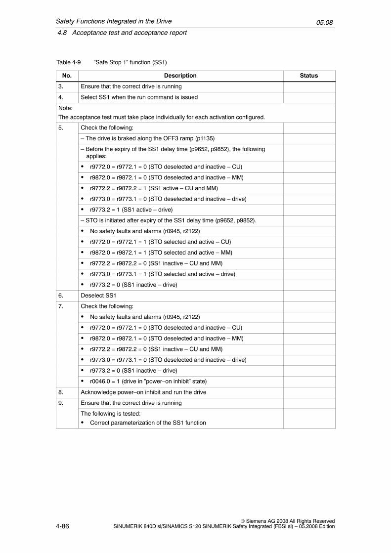
Safety Functions Integrated in the Drive
4.8 Acceptance test and acceptance report
05.08
4-86© Siemens AG 2008 All Rights Reserved
SINUMERIK 840D sl/SINAMICS S120 SINUMERIK Safety Integrated (FBSI sl) – 05.2008 Edition
Table 4-9 ”Safe Stop 1” function (SS1)
No. StatusDescription
3. Ensure that the correct drive is running
4. Select SS1 when the run command is issued
Note:
The acceptance test must take place individually for each activation configured.
5. Check the following:
– The drive is braked along the OFF3 ramp (p1135)
– Before the expiry of the SS1 delay time (p9652, p9852), the followingapplies:
� r9772.0 = r9772.1 = 0 (STO deselected and inactive – CU)
� r9872.0 = r9872.1 = 0 (STO deselected and inactive – MM)
� r9772.2 = r9872.2 = 1 (SS1 active – CU and MM)
� r9773.0 = r9773.1 = 0 (STO deselected and inactive – drive)
� r9773.2 = 1 (SS1 active – drive)
– STO is initiated after expiry of the SS1 delay time (p9652, p9852).
� No safety faults and alarms (r0945, r2122)
� r9772.0 = r9772.1 = 1 (STO selected and active – CU)
� r9872.0 = r9872.1 = 1 (STO selected and active – MM)
� r9772.2 = r9872.2 = 0 (SS1 inactive – CU and MM)
� r9773.0 = r9773.1 = 1 (STO selected and active – drive)
� r9773.2 = 0 (SS1 inactive – drive)
6. Deselect SS1
7. Check the following:
� No safety faults and alarms (r0945, r2122)
� r9772.0 = r9772.1 = 0 (STO deselected and inactive – CU)
� r9872.0 = r9872.1 = 0 (STO deselected and inactive – MM)
� r9772.2 = r9872.2 = 0 (SS1 inactive – CU and MM)
� r9773.0 = r9773.1 = 0 (STO deselected and inactive – drive)
� r9773.2 = 0 (SS1 inactive – drive)
� r0046.0 = 1 (drive in ”power–on inhibit” state)
8. Acknowledge power–on inhibit and run the drive
9. Ensure that the correct drive is running
The following is tested:
� Correct parameterization of the SS1 function

Safety Functions Integrated in the Drive
4.8 Acceptance test and acceptance report
05.08
4-87© Siemens AG 2008 All Rights ReservedSINUMERIK 840D sl/SINAMICS S120 SINUMERIK Safety Integrated (FBSI sl) – 05.2008 Edition
4.8.5 Acceptance test for Safe Brake Control (SBC)
”Safe Brake Control” function (SBC)
This test comprises the following steps:
Table 4-10 ”Safe brake control” (SBC) function
No. Description Status
1. Initial state
� Drive in the ”Ready” state (p0010 = 0)
� STO function enabled (p9601.0 = 1, p9801.0 = 1)
� SBC function enabled (p9602 = 1, p9802 = 1)
� Vertical axis:
Brake as in sequential control (p1215 = 1)
� No vertical axis:
Brake always open (p1215 = 2)
� Vertical axis:
Mechanical brake is closed
� No vertical axis:
Mechanical brake is open
� No safety faults and alarms (r0945, r2122)
� r9772.0 = r9772.1 = 0 (STO deselected and inactive – CU)
� r9872.0 = r9872.1 = 0 (STO deselected and inactive – MM)
� r9773.0 = r9773.1 = 0 (STO deselected and inactive – drive)
� r9772.4 = r9872.4 = 0 (SBC not requested – CU and MM)
2. Run drive (the closed brake is opened)
3. Ensure that the correct drive is running
4. Select STO/SS1 during the traversing command
Note:
The acceptance test must take place individually for each activation configured.
5. Check the following:
� Drive is braked and stopped by the mechanical brake.
� No safety faults and alarms (r0945, r2122)
� r9772.0 = r9772.1 = 1 (STO selected and active – CU)
� r9872.0 = r9872.1 = 1 (STO selected and active – MM)
� r9773.0 = r9773.1 = 1 (STO selected and active – drive)
� r9772.4 = r9872.4 = 1 (SBC requested – CU and MM)
6. Deselect STO

Safety Functions Integrated in the Drive
4.8 Acceptance test and acceptance report
05.08
4-88© Siemens AG 2008 All Rights Reserved
SINUMERIK 840D sl/SINAMICS S120 SINUMERIK Safety Integrated (FBSI sl) – 05.2008 Edition
Table 4-10 ”Safe brake control” (SBC) function, continued
No. StatusDescription
7. Check the following:
� Vertical axis:
Mechanical brake remains closed
� No vertical axis:
Mechanical brake is opened
� No safety faults and alarms (r0945, r2122)
� r9772.0 = r9772.1 = 0 (STO deselected and inactive – CU)
� r9872.0 = r9872.1 = 0 (STO deselected and inactive – MM)
� r9773.0 = r9773.1 = 0 (STO deselected and inactive – drive)
� r9772.4 = r9872.4 = 0 (SBC not requested – CU and MM)
� r0046.0 = 1 (drive in ”power–on inhibit” state)
8. Acknowledge power–on inhibit and run the drive
(Vertical axis: mechanical brake is opened)
9. Ensure that the correct drive is running
The following is tested:
� The brake is correctly connected
� The hardware is functioning correctly
� The SBC is parameterized correctly
� Routine for forced checking procedure of the brake control
4.8.6 Completing the log
Safety Integrated parameters
Were the specified values checked?
Yes No
Control Unit
Motor Module

Safety Functions Integrated in the Drive
4.8 Acceptance test and acceptance report
05.08
4-89© Siemens AG 2008 All Rights ReservedSINUMERIK 840D sl/SINAMICS S120 SINUMERIK Safety Integrated (FBSI sl) – 05.2008 Edition
Checksums
Axis/spindle Checksum (8 hex)
Name Drive number Control Unit Motor Module
Data backup
Storage device Archivinglocation
Type Designation Date
Parameter
PLC program
Circuit diagrams
Countersignatures
System startup engineer
This confirms that the tests and checks have been correctly carried out.
Date Name Company/Department
Signature

Safety Functions Integrated in the Drive
4.8 Acceptance test and acceptance report
05.08
4-90© Siemens AG 2008 All Rights Reserved
SINUMERIK 840D sl/SINAMICS S120 SINUMERIK Safety Integrated (FBSI sl) – 05.2008 Edition
Machine manufacturer
This confirms that the parameterization recorded above is correct.
Date Name Company/Department
Signature

5-91© Siemens AG 2008 All Rights ReservedSINUMERIK 840D sl/SINAMICS S120 SINUMERIK Safety Integrated (FBSI sl) – 05.2008 Edition
Basics on the Safety Functions Integratedin the System/Drive
Motion monitoring functions with a higher–level control
The motion monitoring functions are carried out using a higher–level control. Thehigher–level control and the drive are the two monitoring channels. Just like themonitoring functions integrated in the drive, also here, each channel must be as-signed a shutdown path so that when a fault develops, the pulses can be cancelledindependently of the other channel.
� The shutdown path of the Control Unit is assigned to the drive monitoringchannel.
� The shutdown path of the Motor Module is assigned the control monitoringchannel.
5.1 Monitoring cycle
Setting the monitoring clock cycle time
The axial safety–related functions are monitored cyclically in the monitoring clockcycle that can be set jointly for all axes/spindles using the following machine data:
for 840D slMD 10090: $MN_SAFETY_SYSCLOCK_TIME_RATIOThe specified clock cycle is checked and rounded–off to the next possible valuewhen the control boots and every time the machine data changes.The resulting monitoring clock cycle is displayed using MD 10091:$MN_INFO_SAFETY_CYCLE_TIME(refer to Chapter 8.1.2, ”Description of machine data”).
for SINAMICS S120p9500 SI motion monitoring clock cycle (Control Unit)(refer to Chapter 8.2.2, ”Description of parameters”)
5

Basics on the Safety Functions Integrated in the System/Drive
5.1 Monitoring cycle
05.08
5-92© Siemens AG 2008 All Rights Reserved
SINUMERIK 840D sl/SINAMICS S120 SINUMERIK Safety Integrated (FBSI sl) – 05.2008 Edition
!Warning
The monitoring clock cycle determines the response time of the safety–relatedfunctions. It must therefore be selected to be <= 25 ms. The higher the monitoringcycle setting, the greater the amount by which the monitored limit value is violatedin the event of an error and the more that the drive(s) overshoots.

Basics on the Safety Functions Integrated in the System/Drive
5.2 Crosswise data comparison
05.08
5-93© Siemens AG 2008 All Rights ReservedSINUMERIK 840D sl/SINAMICS S120 SINUMERIK Safety Integrated (FBSI sl) – 05.2008 Edition
5.2 Crosswise data comparison
The continuous comparison of the safety–related data in the monitoring channelscarried out in the SI monitoring clock cycle is known as ”crosswise data compari-son” (CDC).
The following apply to the axial monitoring functions: In the case of ”non–steady–state” data, tolerance values defined using machine data are used by whichamount the results of the two channels may deviate from one another without initi-ating a response (e.g. tolerance for crosswise data comparison of actual positions).
A distinction is made between:
� Drive CDC between the drive and Motor Module (refer to Chapter 4 ”SafetyFunctions Integrated in the Drive”).
� Axis CDC between the NCK and drive (refer to Chapter 6 ”Safety FunctionsIntegrated in the System/Drive”).
� Communication CDC between the NCK and PLC (refer to Chapter 7.2,”Connecting I/O via PROFIsafe”).
� SPL CDC between the NCK and PLC (refer to Chapter 7.3, ”Safe program-mable logic (SPL)”).
Error response
If the crosswise data comparison identifies an error, then this results in a stopresponse (refer to Chapter 6.3, ”Safe Stops A–F”).
In addition, safety alarms are output.
Note
If SGEs are quickly changed over several times this can initiate a STOP F.
Displays the crosswise data comparison clock cycle
To display the actual crosswise data comparison cycle time between the NCK anddrive, the axial MD 36992 is used: $MA_SAFE_CROSSCHECK_CYCLE and thegeneral MD 10092: $MN_INFO_CROSSCHECK_CYCLE_TIME. If the monitoringclock cycle is modified, then the crosswise comparison clock cycle is alsochanged.

Basics on the Safety Functions Integrated in the System/Drive
5.3 Forced checking procedure
05.08
5-94© Siemens AG 2008 All Rights Reserved
SINUMERIK 840D sl/SINAMICS S120 SINUMERIK Safety Integrated (FBSI sl) – 05.2008 Edition
5.3 Forced checking procedure
Forced checking procedure, general (extract from /6/)
”...A forced checking procedure must be carried out for all static (steady–stage)signals and data. Within the required time (8 h), the state must change from a log-ical 1 to a logical 0 – or vice versa. If the state remains static in a fault situation,then this is detected at the latest as a result of this forced checking procedure andthe subsequent comparison.
A forced checking procedure must be used, e.g. for components that are requiredto stop a process (e.g. contactors and power semiconductors) – the so–calledshutdown path and for the shutdown condition. Generally, it is not possible to test ashutdown condition, e.g. violation of a limit value criterion, using other methodssuch as e.g. crosswise data comparison, when the machine is in an acceptable(good) condition. This also applies to errors along the entire shutdown path includ-ing associated hardware and software and circuit–breakers.By integrating a test stop every eight hours with a comparison and expected sta-tus, faults can also be detected when the machine is in an acceptable (good) con-dition....”(Comment: Acceptable (good) condition means that there are no machine faultsthat are apparent to the operator).(Comment: For Safety Integrated, a forced checking procedure interval of one yearis permissible)
Forced checking procedure with Safety Integrated
The forced checking procedure is used to detect faults/errors in the software andhardware of the two monitoring channels. In order to do this, the safety–relatedparts in both channels must be processed at least once during a defined period inall safety–related branches. Any faults/errors in the monitoring channel wouldcause deviations and will be detected by the cross–wise data comparison.
For Safety Integrated, the forced checking procedure interval is max. 1 year. Thisinvolves components from the SINUMERIK 840D sl/SINAMICS S120 system. Pos-sible requirements relating to shorter forced checking procedure intervals of safe-ty–related components (e.g. PROFIsafe I/O modules, sensors such as e.g. emer-gency stop buttons, actuators such as e.g. brakes, etc.) are not influenced.
The forced checking procedure must be initiated by the user or integrated in theprocess as an automatic procedure, e.g.:
� When the axes are stationary after the system has been powered–up
� When the protective door is opened
� In defined cycles (e.g. every 8 hours – a maximum of once every year is per-missible).
� In the automatic mode, dependent on the time and event.

Basics on the Safety Functions Integrated in the System/Drive
5.3 Forced checking procedure
05.08
5-95© Siemens AG 2008 All Rights ReservedSINUMERIK 840D sl/SINAMICS S120 SINUMERIK Safety Integrated (FBSI sl) – 05.2008 Edition
The forced checking procedure also includes testing the safety–related sensorsand actuators at the safety–related inputs/outputs. In this case, the entire circuitincluding the ”Safe Programmable Logic” (SPL) is tested to ensure that it is cor-rectly functioning (refer to Chapter 7.1.2, ”Forced checking procedure of SPL sig-nals”).
!Warning
The test interval duration of max. 1 year may only be extended under the followingconditions:
� In the time after the test interval has expired, no hazards for personnel may beallowed to occur – they must be completely excluded (e.g. the protective dooris closed and is also interlocked)
� After the test interval has expired, before a possible hazard to personnel (e.g.for a request to open a protective door), a test stop or a forced checkingprocedure must be carried out to absolutely ensure the availability of theshutdown paths and the safety–related inputs/outputs.
This means that for the duration of the automatic mode (with the protective doorclosed and interlocked), a fixed cycle is not strictly specified. After expiry of thetime, the forced checking procedure can be carried out before the next opening ofthe protective door.
Note
If the crosswise data comparison identifies an error, then this results in a stopresponse (refer to Chapter 6.3, ”Safe Stops A–F”).

Basics on the Safety Functions Integrated in the System/Drive
5.4 Actual value conditioning
05.08
5-96© Siemens AG 2008 All Rights Reserved
SINUMERIK 840D sl/SINAMICS S120 SINUMERIK Safety Integrated (FBSI sl) – 05.2008 Edition
5.4 Actual value conditioning
5.4.1 Encoder types
Basic types
The following basic encoder types can be used with a drive module to implementsafety–related operation:
1. Incremental encoder via a Sensor Module and DRIVE–CLiQwith sinusoidal voltage signals A and B (signal A is shifted with respect to Bthrough 90° and a reference signal R, e.g.: ERN 1387, LS 186, SIZAG2
2. Absolute encoder via Sensor Module and DRIVE–CLiQwith an EnDat interface and incremental sinusoidal voltage signals A and B(signal A is shifted with respect to B through 90°), e.g.: EQN 1325, LC 181
3. Motor encoder (IMS) with integrated DRIVE–CLiQ interface, with the propertiescorresponding to 1. or 2.
4. Direct encoder (DMS, e.g. linear scale) with integrated DRIVE–CLiQ interface,with the properties corresponding to 1. or 2.
Combining encoder types
Various combinations can be derived from the basic types.
Table 5-1 Combining encoder types
Incremental encoder Absolute encoders
at the motor at the load at the motor at the load Comments
x 1–encoder system
x 1–encoder system
x x 2–encoder system
x x 2–encoder system
x x 2–encoder system
x x 2–encoder system
Note: x –> encoder connection

Basics on the Safety Functions Integrated in the System/Drive
5.4 Actual value conditioning
05.08
5-97© Siemens AG 2008 All Rights ReservedSINUMERIK 840D sl/SINAMICS S120 SINUMERIK Safety Integrated (FBSI sl) – 05.2008 Edition
1–encoder system
For a 1–encoder system, the incremental or absolute encoder of the motor is usedfor the safety–related actual values of the NC and drive.The actual values are generated in a safety–related fashion either directly in theencoder or in the Sensor Module and are provided – with no–reaction – to the NCKand the drive using safety–related communications via DRIVE–CLiQ.
Special feature regarding linear motors:For linear motors, the motor encoder (linear scale) is also the measuring system atthe load. IMS and DMS are one measuring system. The connection is made at theIMS input of the Sensor Module or directly via DRIVE–CLiQ.
Significance of the coarse encoder position:For a 1–encoder system, for all position monitoring functions, the accuracy of theredundant actual value must be assumed to apply. This accuracy depends on theencoder evaluation. For all encoder evaluation functions that can be used withSafety Integrated (SME, SMC, motor with DRIVE–CLiQ), the coarse encoderpulses are redundantly counted including the quadrupling (coarse encoder posi-tion). The machine manufacturer must select the appropriate encoder with the nec-essary encoder pulse number for his particular requirements. To do this, the en-coder resolution must be converted to the accuracy on the load side. Thisconversion is dependent on the type of encoder mounting and the type of axis.Further, gearbox factors, the spindle pitch for linear axes and the radius of therotary table for rotary axes must also be taken into account.
Encoder Gear
Back–
Machine table
Motor(FD)
DRIVE–CLiQ
Sensor Module cabinet mounted (not usedfor encoders with DRIVE–CLiQ interface)
lash
Fig. 5-1 1–encoder system for a feed drive (FD)

Basics on the Safety Functions Integrated in the System/Drive
5.4 Actual value conditioning
05.08
5-98© Siemens AG 2008 All Rights Reserved
SINUMERIK 840D sl/SINAMICS S120 SINUMERIK Safety Integrated (FBSI sl) – 05.2008 Edition
!Warning
The specific residual risks for 1 encoder systems (refer to Chapter 3.5 ”Residualrisks”) must be carefully taken into consideration.
2–encoder system
In this case, the safety–related actual values for an axis are supplied from 2 sepa-rate encoders. In standard applications, the drive evaluates the motor encoder(IMS) and the NC, the measuring system (DMS). The actual values are generatedin a safety–related fashion either directly in the encoder or in the Sensor Moduleand are provided – with no–reaction – to the NCK and the drive using safety–related communications via DRIVE–CLiQ. A separate connection or a separateSensor Module is required for every measuring system.
DRIVE–CLiQ
Sensor Module cabinet mounted(not used for encoders withDRIVE–CLiQ interface)
Encoder GearBack–
Linear scaleMachine table
Motor (FD) lash
Fig. 5-2 2–encoder system for a feed drive (FD), connected through 2 Sensor Modules

Basics on the Safety Functions Integrated in the System/Drive
5.4 Actual value conditioning
05.08
5-99© Siemens AG 2008 All Rights ReservedSINUMERIK 840D sl/SINAMICS S120 SINUMERIK Safety Integrated (FBSI sl) – 05.2008 Edition
DRIVE–CLiQ
Sensor Module cabinet mounted (not usedfor encoders with DRIVE–CLiQ interface)
Spindle
Incrementalencoder
Incremental encoder
Controlgear
Motor(MSD)
Fig. 5-3 2–encoder system for the main spindle, connected via 2 Sensor Modules
NoteFor systems with slip, refer to Chapter 5.4.6, ”Actual value synchronization (slip for2–encoder systems)”.
5.4.2 Encoder adjustment, calibrating the axes
Adjusting the motor encoder
Generally, for 1–encoder systems, the integrated encoder is an integral componentof the motor (the encoder is adjusted to match the motor). Data relating todistance, speed and rotor position (for synchronous drives) is obtained from oneencoder. It is no longer possible to adjust the encoders in motor measuring sys-tems in the conventional sense.

Basics on the Safety Functions Integrated in the System/Drive
5.4 Actual value conditioning
05.08
5-100© Siemens AG 2008 All Rights Reserved
SINUMERIK 840D sl/SINAMICS S120 SINUMERIK Safety Integrated (FBSI sl) – 05.2008 Edition
Calibrating the machine
The machine zero and encoder zero are calibrated purely on the basis of the offsetvalue (the machine must be calibrated). This procedure must be carried out forboth absolute and incremental encoders.
Absolute encoder actual value
Actual position valueOffset value
Encoderzero
Machinezero
Switch–onposition/stopposition
Fig. 5-4 Positions and actual values
When calibrating the machine, a known or measured position is approached usinga dial gauge, fixed stop, etc. and the offset determined. This offset is then enteredinto the appropriate machine data. Calibration must always be carried out for posi-tion–controlled (closed–loop) axes/spindles.
References: /IAD/, Commissioning Manual SINUMERIK 840D sl/FBD/, Description of Functions, SINUMERIK 840D sl,
R1, ”Reference point approach”
5.4.3 Axis states
”Axis not referenced” state
The axis state ”axis not referenced” is reached after the power supply has beenpowered–up and the drive and control system have completely booted. This stateis indicated using the axis–specific interface signal ”reference point reached” asfollows:
Interface signal ”Reference point reached” = ”1” Axis state ”Axis referenced””Reference point reached” = ”0” Axis state ”Axis not referenced”
for 840D sl DB31–61, DBX60.4/DBX60.5
(refer to Fig. 5-5 ”Axis states when referencing”)

Basics on the Safety Functions Integrated in the System/Drive
5.4 Actual value conditioning
05.08
5-101© Siemens AG 2008 All Rights ReservedSINUMERIK 840D sl/SINAMICS S120 SINUMERIK Safety Integrated (FBSI sl) – 05.2008 Edition
”Axis referenced” state
For incremental encoders, the position actual value is lost when the NC is pow-ered–down. When the NC is powered–up, a reference point approach must be car-ried out. If this is executed correctly, then the axis is referenced and goes into the”axis referenced” state (refer to 5-5 ”Axis states when referencing”).
Contrary to incremental encoders, absolute encoders do not require a referencepoint approach after the NC has been powered–up. These encoders track the ab-solute position, e.g. using a mechanical gear, both when powered–up and pow-ered–down. The absolute position is transferred implicitly via a serial interfacewhen the NC is powered–up. After the position data has been transferred and theoffset value has been taken into account, the axis also goes in the axis state ”axisreferenced” (refer to Fig. 5-5 ”Axis states when referencing”).
This axis state ”axis referenced” is indicated using the axis–specific interface signal”reference point reached” as follows:
Interface signal ”Reference point reached” = ”1” Axis state ”Axis referenced””Reference point reached” = ”0” Axis state ”Axis not referenced”
for 840D sl DB31–61, DBX60.4/DBX60.5
References: /IAD/, Commissioning Manual, SINUMERIK 840D sl
”Axis safely referenced” state
In order to reach the axis state ”axis safely referenced”, the axis state ”axis refer-enced” must have been reached, and either
� the user confirms the current position using the user agreement (refer to Chap-ter 5.4.4 ”User agreement”
or
� a saved and set user agreement and saved stop position when the system waspowered–down must exist. The position associated with the saved data mustmatch the current position within a tolerance window. This is checked both inthe drive and in the NC.
(refer to Fig. 5-5 ”Axis states when referencing”).
The axis state ”axis safely referenced” is displayed using the SGA ”axis safelyreferenced”. A safety–related position evaluation can only be carried out for the SEand SN functions after this state has been reached.
Saved user agreement
The state of the user agreement function is saved in non–volatile memories. Thissaved user agreement forms, together with the stop position, also saved in a non–volatile fashion the prerequisite for the axis state ”axis safely referenced”.

Basics on the Safety Functions Integrated in the System/Drive
5.4 Actual value conditioning
05.08
5-102© Siemens AG 2008 All Rights Reserved
SINUMERIK 840D sl/SINAMICS S120 SINUMERIK Safety Integrated (FBSI sl) – 05.2008 Edition
Saved stop position
The saved stop position data is combined with the permanently saved user agree-ment to form the previous history.
The following must be noted when the stop position is saved:
The following applies when SE/SN is active:
� The stop position is also cyclically saved.
� If the axis is moved with the system powered–down, then the saved stop posi-tion no longer matches the current position.
As described under ”axis safely referenced” the ”axis safely referenced” state canalso be achieved using a saved and set user agreement and a saved stop position.
The following conditions must be fulfilled:
� The saved user agreement must be available.
� The difference between the ”reference position” (power–on position with abso-lute measuring systems or reference position for incremental measuring sys-tems) and the saved stop position (including the traversing distance to the refer-ence point with ERN) must be within a tolerance window specified using theappropriate machine data.

Basics on the Safety Functions Integrated in the System/Drive
5.4 Actual value conditioning
05.08
5-103© Siemens AG 2008 All Rights ReservedSINUMERIK 840D sl/SINAMICS S120 SINUMERIK Safety Integrated (FBSI sl) – 05.2008 Edition
Axis safelyreferenced
Axis status
No
Check OK
Yes
Axis status
Axis status
SBH/SG is safefrom this axis
status onwards Axis notreferenced
Axis referenced(homed)
SE/SN is safefrom this axis
status onwards
Check notOK
User checks the position
User agreement (softkey)
SGA”Axis safely referenced” = ”1”
Axis status is displayed using:Interface signal ”reference point reached” = ”0”
EQN: Read the absolute value from the encoderERN: Reference point approach
Interface signal ”reference point reached” = ”1”
Useracknowledgement
Check, actualposition/saved stop
position
Fig. 5-5 Axis states when referencing
5.4.4 User acknowledgement
Description
With a user agreement, an appropriately authorized person confirms that the cur-rently displayed SI actual position of an axis corresponds to the actual position atthe machine.This can be checked by traversing the axis to a known position (e.g. a visual mark)or the axis is adjusted/calibrated and the SI actual position is therefore comparedin the ”user agreement” screen.
An axis/spindle with integrated safety functions can have the following status:User agreement = yes, orUser agreement = no

Basics on the Safety Functions Integrated in the System/Drive
5.4 Actual value conditioning
05.08
5-104© Siemens AG 2008 All Rights Reserved
SINUMERIK 840D sl/SINAMICS S120 SINUMERIK Safety Integrated (FBSI sl) – 05.2008 Edition
All safety axes are listed in the HMI display ”user agreement” for which safety endstops and/or safety cams have been activated. The following data are displayed:
� Machine–axis name� SI position� User acknowledgement
When does a user agreement have to be given?
A user agreement is always required if an axis/spindle is to be monitored for SE, SN.
A user agreement is only required:
– when the axis/spindle is commissioned for the first time.
– when the user intends or needs to again manually and safely reference theaxis/spindle.
– If, after Power On, the stop position did not correspond with the actual posi-tion and the control cancelled the user agreement.
– after parking an axis/spindle(only if the change in position is greater than that defined using MD 36944:$MA_SAFE_REFP_POS_TOL tolerance actual value comparison (referenc-ing) is defined).
Note
An axis/spindle must have the status User agreement = yes before the SN and SEfunctions can be used.
For axes/spindles without the safety ”SE” and ”SN” functions, the saved stopposition position is not evaluated.
!Warning
If the drive has not been safely referenced and a user agreement has not beengiven, then the following applies:– The ”Safe software cams” and/or ”Safe cam track” are active, but are not
safety–relevant.– The ”Safe software limit switches” are not active.
The user agreement can only be set by an authorized user.
The user agreement can be cancelled by the user or as a result of a function beingselected (e.g. new gear stage) or also an incorrect state (e.g. inconsistency in theuser agreement between the NC and drive). When the user agreement is can-celled, the axis state ”axis safely referenced” is always reset(refer to Fig. 5-5 ”Axis states when referencing”).

Basics on the Safety Functions Integrated in the System/Drive
5.4 Actual value conditioning
05.08
5-105© Siemens AG 2008 All Rights ReservedSINUMERIK 840D sl/SINAMICS S120 SINUMERIK Safety Integrated (FBSI sl) – 05.2008 Edition
Interlocking the user agreement
Before a user agreement can be issued, the interlock must be cancelled:
� KeySwitchin setting 3 –> the user agreement can be issued
After the user agreement has been issued, the interlocking must be again set (e.g.key switch position 3 must be left and the key withdrawn).
5.4.5 Taking into account control gears
The possible gearbox ratios must be known in order that the NC and drive canevaluate the position actual values referred to the load.
For this purposes, various gearbox ratios can be selected on an axis–for–axis ba-sis in the machine data and selected using the ”Safety–related inputs/outputs”(SGEs/SGAs).
The following points must be carefully observed for drives with control gears (theseare generally used with spindles).
� If the drive is operated with an (indirect) encoder (motor measuring system), i.e.the safety–related actual value for the NCK and drive are derived from thesame measuring system, then the gearbox ratios (gearbox stage selection forSafety Integrated) must also be selected for both monitoring channels. Thestate of the SGE signal ratio selection (bits 0..2) is not subject to a crosswisedata comparison; however, the safety–related actual values from the NCK anddrive are compared to evaluate if there is any deviation (< 36942$MA_SAFE_POS_TOL or parameter p9542 SI motion, actual value comparisontolerance (crosswise) (Control Unit).
� If the drive is operated with an (indirect) motor encoder and a (direct) spindleencoder, the safety–related actual values are derived from the direct encoderand those of the drive from the indirect encoder. For the direct encoder, thegearbox changeover is not relevant and the gearbox stage changeover only hasto be configured/engineered for the drive.
� Using the two machine data fields36921[0..7] $MA_SAFE_ENC_GEAR_DENOM[n] denominator, gearbox encod-er/load andMD 36922[0..7] $MA_SAFE_ENC_GEAR_NUMERA[n] numerator, gearboxencoder/loadorp9521[0..7] SI motion gearbox encoder/load denominator (Control Unit) andp9522[0..7] SI motion gearbox encoder/load numerator (Control Unit)8 different gearbox stage pairs for NCK/drive can be defined. For this definition,there is no special function for an index value – e.g. interdependency on theoperating mode of the spindle. These 8 pairs must be parameterized and se-lected depending on the encoder configuration.

Basics on the Safety Functions Integrated in the System/Drive
5.4 Actual value conditioning
05.08
5-106© Siemens AG 2008 All Rights Reserved
SINUMERIK 840D sl/SINAMICS S120 SINUMERIK Safety Integrated (FBSI sl) – 05.2008 Edition
� As a result of the gearbox stage changeover, the encoder evaluation for thesafety–related actual values change. Ideally, the gearbox stage for Safety Inte-grated is changed–over at standstill. However, this is generally not in–line withwhat is required in practice. This means that the actual value offset whenchanging–over the gearbox stage (e.g. using oscillation) may not be greaterthan the already mentioned actual value tolerance window (MD 36942/p9542).
� If, for the axis with control gear, position–dependent monitoring functions areactivated – such as SE or SN – the user agreement (assuming that it was pre-viously set) is withdrawn when changing–over the gearbox ratio and the SGA”axis safely referenced” is set to 0. When the gearbox stage is changed fromthe PLC and/or by selecting a new ratio, a new gearbox ratio is detected usingthe appropriate SGEs.
� After the gearbox stage has been selected, the spindle must be re–synchro-nized. When re–synchronizing the spindle, the two safety–related actual values(NCK and drive) are re–initialized with the newly synchronized actual value.A possible difference that was previously present between the two safety–related actual values is therefore corrected.
� In order to be able to re–use the SN or SE function after the gearbox ratio hasbeen selected (changed), the user must bring the spindle into the state ”axissafely referenced” – the user agreement must be re–issued.
� For 2–encoder systems, the gearbox ratio does not have to be selected in asafety–related fashion and can be implemented through one channel. On theother hand, for a 1–encoder system, the ratio selection must implemented usingsafety–related technology – i.e. using two channels.
!Warning
When a new stage is selected for a control gear (the ratio changed), an axis isparked or the mounting situation is modified (encoder and motor replaced), thismeans that the load and encoder have been decoupled. The NC and drive cannotdetect this. The state ”axis safety referenced” is no longer applicable.The user is responsible in bringing the axis back into the ”axis safely referenced”state if the functions ”safe software limit switch” or ”safe cams” are used.

Basics on the Safety Functions Integrated in the System/Drive
5.4 Actual value conditioning
05.08
5-107© Siemens AG 2008 All Rights ReservedSINUMERIK 840D sl/SINAMICS S120 SINUMERIK Safety Integrated (FBSI sl) – 05.2008 Edition
5.4.6 Actual value synchronization (slip for 2–encoder systems)
Description of function
When a 2–encoder system is used, SI actual values from the NC and the drive driftapart for systems that have inherent slip. The reason for this is that the drive eval-uates the motor measuring system and the NC evaluates the direct measuringsystem after the gearbox.
There are the following two alternatives in order to avoid this:
� 1–encoder system without actual value synchronization� 2–encoder system with actual value synchronization and therefore additional
monitoring of the load side
Slip tolerance
The actual value is synchronized through two channels. In both channels, machinedata 36949: $MA_SAFE_SLIP_VELO_TOL/parameter p9549 ”SI motion slipvelocity tolerance” is used in which the maximum offset between the NCK anddrive actual value is entered as velocity. The tolerance value entered in MD 36942:$MA_SAFE_POS_TOL is not relevant.
For the actual value synchronization, both channels correct their SI actual positionto half the determined actual value difference. Please note that the two SI actualpositions no longer display the correct absolute position. The NC actual positionand the two SI actual positions are different.
The actual values are synchronized in the crosswise data comparison clock cycle.Actual value synchronization is also performed when a crosswise data comparisonof the SI actual position outputs an error.
Actual values are also synchronized after ”referencing” and for ”parking axis”.
The currently determined and the maximum SI speed difference since the lastreset are displayed in the axis–specific service screen for diagnostic purposes.
In order to define the slip tolerance, in MD 36949: $MA_SAFE_SLIP_VELO_TOLthe maximum differential speed is set. As a result of an action, such as e.g. maxi-mum acceleration when starting, gearbox stage changes with oscillation, a situa-tion is created where the actual values drift apart. This value can be taken as nom-inal value from the diagnostics screen ”Maximum velocity difference”, multiplied bya factor of 1.5 and then entered into MD 36949.
Note
Actual values are only synchronized when there is an actual value differencebetween the two channels of 2 �m or 2 m degrees in each SI monitoring clockcycle.

Basics on the Safety Functions Integrated in the System/Drive
5.4 Actual value conditioning
05.08
5-108© Siemens AG 2008 All Rights Reserved
SINUMERIK 840D sl/SINAMICS S120 SINUMERIK Safety Integrated (FBSI sl) – 05.2008 Edition
Limitations
The two SI actual positions no longer display the correct absolute machine posi-tion. The correct position can now only be read out via the NC actual position.
The safety monitoring functions SG, SBH, SBR and ”n<nx” still only respond toactual value changes from the particular actual value acquisition channel – not tochanges in the actual value resulting from the actual value synchronization. Asingle–channel SG violation only initiates an alarm in the channel in which thisspeed violation was detected. The associated stop response is therefore still initi-ated through two channels.
SGA ”n<nx” can also assume different static states in the two monitoring channels.
Note
It is not possible to activate the safe SE and SN functions for an axis/spindlewhere slip can occur between the motor and the load.
Activating
The actual value synchronization is selected by setting bit 3 in machine data36901: $MA_SAFE_FUNCTION_ENABLE or parameter p9501:” SI motion, enablesafety–related functions”. In addition, SI function ”SBH/SG monitoring” must alsobe enabled.
Actual value synchronization is only permissible if a monitoring function with abso-lute reference has not been enabled. If SE and/or SN are also selected, power onAlarms 27033 and F01688 are also output when booting.
The actual value synchronization is only permissible for 2–encoder systems. If thisfunction is enabled for a single–encoder system, Alarm 27033/F01688 is output.
5.4.7 Encoder limit frequency
For safety–related operation, it is not permissible that the encoder limit frequencyof 500 kHz exceeded.For this purposes, Safety Integrated monitors for the encoder limit frequency beingexceeded depending on the situation (depending on the context); when the en-coder limit frequency is exceeded, an appropriate alarm is output (refer to Chapter6.5 ”Safely reduced speed”)

Basics on the Safety Functions Integrated in the System/Drive
5.5 Enabling the safety–related functions
05.08
5-109© Siemens AG 2008 All Rights ReservedSINUMERIK 840D sl/SINAMICS S120 SINUMERIK Safety Integrated (FBSI sl) – 05.2008 Edition
5.5 Enabling the safety–related functions
Global enableSINUMERIK Safety Integrated (SI) with the safety–related functions is enabledusing options.The enable signal determines the number of axes/spindles for which SI can be ac-tivated. Using an additional options, in addition, the number of possible SPL–SGE/SGAs is defined.The SH/SBC/SS1 function is completely implemented in SINAMICS S120 and is,as a function integrated in the drive, included in the basic drive scope.
Enabling safety–related functions
Which safety functions are to be effective can be individually selected for each axisusing the following machine data:
for 840D slMD 36901: $MA_SAFE_FUNCTION_ENABLE(refer to Chapter 8.1, ”Machine data for SINUMERIK 840D sl”)
for S120p9501: SI motion enable safety functions (Control Unit)(refer to Chapter 8.2, ”Parameters for SINAMICS S120”)
Among others, the following functions can be individually enabled:
� SBH/SG
� SE
� SN
� SG override
� Actual value synchronization
� External STOPs
� Cam synchronization
� STOP E

Basics on the Safety Functions Integrated in the System/Drive
5.5 Enabling the safety–related functions
05.08
5-110© Siemens AG 2008 All Rights Reserved
SINUMERIK 840D sl/SINAMICS S120 SINUMERIK Safety Integrated (FBSI sl) – 05.2008 Edition
Note
� To ensure that SBH can always be selected in the event of an error, thefunction SBH/SG must be activated and appropriately parameterized when thefunction SE and/or SN are(is) enabled.
� The axis–specific enable data in the NCK must match those in the drive,otherwise, the crosswise data comparison signals an error.
� An SI axis is treated as an axis in terms of the global option if at least onesafety–related function is activated via the axis–specific enable data.
� The maximum number of axes that may operate with SI and SPL SGE/SGAs isthe number that was enabled using the options.
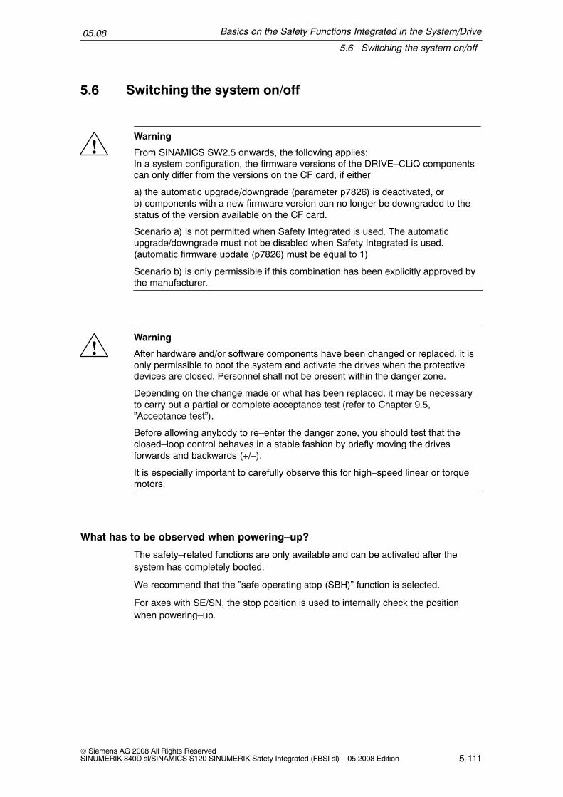
Basics on the Safety Functions Integrated in the System/Drive
5.6 Switching the system on/off
05.08
5-111© Siemens AG 2008 All Rights ReservedSINUMERIK 840D sl/SINAMICS S120 SINUMERIK Safety Integrated (FBSI sl) – 05.2008 Edition
5.6 Switching the system on/off
!Warning
From SINAMICS SW2.5 onwards, the following applies:In a system configuration, the firmware versions of the DRIVE–CLiQ componentscan only differ from the versions on the CF card, if either
a) the automatic upgrade/downgrade (parameter p7826) is deactivated, orb) components with a new firmware version can no longer be downgraded to thestatus of the version available on the CF card.
Scenario a) is not permitted when Safety Integrated is used. The automaticupgrade/downgrade must not be disabled when Safety Integrated is used.(automatic firmware update (p7826) must be equal to 1)
Scenario b) is only permissible if this combination has been explicitly approved bythe manufacturer.
!Warning
After hardware and/or software components have been changed or replaced, it isonly permissible to boot the system and activate the drives when the protectivedevices are closed. Personnel shall not be present within the danger zone.
Depending on the change made or what has been replaced, it may be necessaryto carry out a partial or complete acceptance test (refer to Chapter 9.5,”Acceptance test”).
Before allowing anybody to re–enter the danger zone, you should test that theclosed–loop control behaves in a stable fashion by briefly moving the drivesforwards and backwards (+/–).
It is especially important to carefully observe this for high–speed linear or torquemotors.
What has to be observed when powering–up?
The safety–related functions are only available and can be activated after thesystem has completely booted.
We recommend that the ”safe operating stop (SBH)” function is selected.
For axes with SE/SN, the stop position is used to internally check the positionwhen powering–up.

Basics on the Safety Functions Integrated in the System/Drive
5.6 Switching the system on/off
05.08
5-112© Siemens AG 2008 All Rights Reserved
SINUMERIK 840D sl/SINAMICS S120 SINUMERIK Safety Integrated (FBSI sl) – 05.2008 Edition
!Warning
When the system boots, this represents a critical operating state with increasedrisk. In this phase, especially when activating drives, it is not permissible thatpersonnel are close to the hazardous area.Further, for vertical axes, it is very important to ensure that the drives are in astate with the pulses cancelled.
A complete forced checking procedure after powering–up (refer to Chapter 5.3,”Forced checking procedure”).
What has to be observed when powering–down?
– The following applies when SE/SN is activated:The stop position is also cyclically saved.For this reason, the user should only power–down the control when theaxes/spindles with safety functions have stopped moving.
Note
If the axis is moved with the system powered–down, then the saved stop position no longer matches the current position. For axes with safety SE and SNfunctions, when powering–up, a user agreement is again required after theposition has been checked.

6-113© Siemens AG 2008 All Rights ReservedSINUMERIK 840D sl/SINAMICS S120 SINUMERIK Safety Integrated (FBSI sl) – 05.2008 Edition
Safety Functions Integrated in the System/Drive
6.1 Safe stop (SH)
Note
This Chapter describes the safety function ”safe standstill” (SH), controlled fromthe safety–related motion monitoring functions. The function is based on the safetyfunctions STO/SBC of the drive (see Chapter 4). Fig. 6-1 shows theinterrelationships.The safety functions STO, SBC and SS1, integrated in the drive, controlled via thedrive terminals, are described in Chapter 4. Control via terminals and from themotion monitoring functions is in parallel and can be used independently of oneanother.A Stop A/STO initiated in the drive (i.e. a system error in the drive orSTO/SBC/SS1 selection via terminal) is however not available as two–channelSGA ”STOP A/B active” for the safety–related motion monitoring functions. Thereis only a single–channel signal ”pulses cancelled” present.
Description
The ”safe standstill” function is based on the pulse cancellation (start inhibit) func-tion integrated in the Motor Modules of the SINAMICS S120 (see Chapter 4.2,”Safe Torque Off (STO)”.
There are two shutdown paths that are independent of one another that ensurethat when a component fails, the drive is always brought into a safe condition.
The safe standstill function safely disconnects the energy feed to the motor in theevent of a fault or in conjunction with a machine function.
The following must be carefully observed when controlling/energizing SH from themotion monitoring functions.
– The safety functions STO/SBC/SS1 integrated in the drive are, correspond-ing to the description in Chapter 4 ”Safety Functions Integrated in the Drive”fully effective (parameters, alarms etc.). The standard pre–assignment(default setting) of the associated parameters is generally sufficient in thecontext of the motion monitoring functions.
6

Safety Functions Integrated in the System/Drive
6.1 Safe stop (SH)
05.08
6-114© Siemens AG 2008 All Rights Reserved
SINUMERIK 840D sl/SINAMICS S120 SINUMERIK Safety Integrated (FBSI sl) – 05.2008 Edition
– The safety function STO integrated in the drive does not have to be explicitlyenabled; this is implicitly enabled by enabling the motion monitoring func-tions (p9501 < > 0). If the safety function SBC integrated in the drive is to beadditionally activated when selecting STO, then this however must be explic-itly enabled.
– The PROFIsafe drive address must be set.
!Warning
If the ”safe standstill” function or ”STOP A” is activated, the motor can no longergenerate any torque. This is the reason that potentially hazardous motion canoccur, e.g. for the following:
� When an external force acts on the drive axes� Vertical and inclined axes without weight equalization� Axes that are moving (coasting down)� Direct drives with low friction and low self–locking� Notching torques (depending on the motor type, bearing design and friction
characteristics, up to half a pole pitch in a direction that cannot be predicted).
Possible hazards must be clearly identified using a risk analysis that must becarried out by the manufacturer. With an assessment, based on this risk analysis,it should be defined as to which additional measures are required, e.g. externalbrakes.
Features
The main features of the safe standstill function are as follows:
� The motor cannot be started unintentionally or accidentally
� The energy feed to the motor is safely disconnected
� The Motor Module and motor are not electrically isolated from one another
Selecting/deselecting SH
The ”safe standstill” function corresponds to an external STOP A. This makes itpossible to explicitly select SH, not only using internal events (STOP A when a limitvalue is violated), but also via SGE.
� Safe standstill is activated after a STOP A.� Safe standstill is automatically activated from every monitoring channel when
testing the shutdown paths.
!Warning
After the machine has been powered–up, the ”safe standstill” function must alwaysbe tested for all of the axes/spindles by testing the shutdown path using SafetyIntegrated.

Safety Functions Integrated in the System/Drive
6.1 Safe stop (SH)
05.08
6-115© Siemens AG 2008 All Rights ReservedSINUMERIK 840D sl/SINAMICS S120 SINUMERIK Safety Integrated (FBSI sl) – 05.2008 Edition
6.1.1 Shutdown paths
The interaction of the safety functions integrated in the drive and the motion moni-toring functions (Motion Monitor) are shown in Fig. 6-1.
NCU
NCKMotion Monitor
MM
DriveMotion Monitor
Drive (CU)SI, integrated
Drive (MM)
Shutdown pathNCK
Pulse cancelation
Shutdown path MMPulse cancelation
Shutdown path CU(Motor Module)
Safeprogrammablelogic (SPL)
SGE/SGASGE/SGA
Pulse cancelation
ext. SGE ext. SGA
Optional:
via terminal
Cycl. data for SI,integrated in thedrive (CDC, ...)
Cycl. SI data(including SGE/SGA,CDC data)
� 1
Pulsecancelation
� 1
Optional:
via terminal
STO/SBC/SS1 selection
STO/SBC/SS1 selection
in the drive
SI, integrated in the drive
Fig. 6-1 Overview of the shutdown paths
Shutdown path of the monitoring channel, drive
The motion monitoring function in the CU signals the monitoring function integratedin the drive in the CU that the pulses must be cancelled in the SI monitoring chan-nel integrated in the drive.

Safety Functions Integrated in the System/Drive
6.1 Safe stop (SH)
05.08
6-116© Siemens AG 2008 All Rights Reserved
SINUMERIK 840D sl/SINAMICS S120 SINUMERIK Safety Integrated (FBSI sl) – 05.2008 Edition
� Drive (CU) SI, integrated in the drive– The requirement to cancel the pulses is detected. Mechanisms then start
that are also executed when STO is selected for the safety functions integra-ted in the drive:– Initiating the pulse cancellation– The timer routine is started to check the feedback. After the timer has
expired (in the next monitoring clock cycle integrated in the drive), usingthe feedback signal, it is checked as to whether the pulses have beencancelled via this shutdown path.
– If p9602=1, then safe brake control is executed.
Shutdown path of the monitoring channel, control
If the higher–level control with its motion monitoring identifies that it is necessary tocancel the pulses, then the following sequence applies:
� NCK Motion Monitor– The control communicates to the Motor Modules the requirements to cancel
the pulses.
� Drive (MM), SI, integrated in the drive– If the drive–integrated monitoring function in the Motor Module identifies the
requirement to cancel the pulses, then the same mechanisms are startedthat are carried out for an STO selection of the safety functions integrated inthe drive and an STO is initiated:– Initiating the pulse cancellation– The timer routine is started to check the feedback. After the timer has
expired (in the next monitoring clock cycle integrated in the drive), usingthe feedback signal, it is checked as to whether the pulses have beencancelled via this shutdown path.
– If p9802=1, then safe brake control is executed.
– If the Motor Module detects that communications to the NCK have failed,then this is identified by the safety functions integrated in the drive and anSTO is initiated.
6.1.2 Testing the shutdown paths
Description
The test stop is used to check the shutdown paths of both monitoring channels.There is a test stop input (drive SGE). The acknowledgement is realized via thedrive SGA ”status pulses cancelled”. The pulse cancellation must be simulta-neously initiated through both shutdown paths due to the fact that the Motor Mod-ules and drive closed–loop control are cross–checked.
The user (machine manufacturer) must configure the execution of the test stopphase.

Safety Functions Integrated in the System/Drive
6.1 Safe stop (SH)
05.08
6-117© Siemens AG 2008 All Rights ReservedSINUMERIK 840D sl/SINAMICS S120 SINUMERIK Safety Integrated (FBSI sl) – 05.2008 Edition
Note
A test stop can be simultaneously made for all axes of a drive unit.
Instant in time of the test stop
The shutdown paths must be tested (forced checking procedure) at a suitable in-stant in time. This is generally carried out after the machine has been powered–upand afterwards in the setting–up mode once within a maximum of 8 hours. We rec-ommend that the test is carried out before opening protective devices/guards orwhen the hazardous area is entered (e.g. when selecting the setting–up mode) ifthe shutdown paths were not tested in the last 8 hours.
Note
The machine manufacturer should define the ”test shutdown paths” time in anappropriate ”test block”.
Note
If the brake control is enabled, then when the test stop is initiated, the brake isalso controlled.
Prerequisites for the test stop
� At the start, the pulses must still be enabled; further, it is not permissible thatSH is selected at the start.
� For vertical (suspended) axes, the manufacturer must ensure that these arelocked (to stop them falling).
Note
The test stop can be carried out independently of the status of the standard pulsecancellation.
Message
The ”test stop running” message is displayed during the ”test stop”.

Safety Functions Integrated in the System/Drive
6.2 Safe operating stop (SBH)
05.08
6-118© Siemens AG 2008 All Rights Reserved
SINUMERIK 840D sl/SINAMICS S120 SINUMERIK Safety Integrated (FBSI sl) – 05.2008 Edition
6.2 Safe operating stop (SBH)
Description
The SBH function safely monitors the stop position (zero speed) of an axis/spindlein closed–loop position or speed control.
When SBH is active (SGA ”SBH active” = 1), operating personnel can, for exam-ple, enter protected machine areas in the setting–up mode without first having topower–down the machine.
An incremental encoder is sufficient to implement this function. The actual positionvalue is monitored for a change.
In this case, the encoder coarse position must be taken into account for a 1–en-coder system (see Chapter 5.4 ”Actual value conditioning”).
Features
The features of the SBH function are as follows:
� The axis remains in closed–loop control
� Parameterizable SBH tolerance window
� STOP B is the stop response after SBH has responded
Zero speed tolerance
The standstill of the axis/spindle is monitored using an SBH tolerance window thatis parameterized using the following machine data:
for 840D sl:MD 36930: $MA_SAFE_STANDSTILL_TOL
for SINAMICS S120:p9530: SI motion standstill tolerance (Control Unit)
Note
The width of the SBH tolerance window should be based on the standstill (zerospeed) monitoring limit and should lie slightly above it. Otherwise, the standardmonitoring functions of the control could be ineffective. In this case, the encodercoarse position must be taken into account for a 1–encoder system (see Chapter5.4 ”Actual value conditioning”).

Safety Functions Integrated in the System/Drive
6.2 Safe operating stop (SBH)
05.08
6-119© Siemens AG 2008 All Rights ReservedSINUMERIK 840D sl/SINAMICS S120 SINUMERIK Safety Integrated (FBSI sl) – 05.2008 Edition
Zero speed tolerance = =
v
s(actual value)
Fig. 6-2 Zero speed tolerance
Prerequisites
The following prerequisites must be fulfilled (see Chapter 3.1, ”System require-ments”):
� The option and functions must be enabled in the axis–specific machine data
� The SGEs ”SBH/SG deselection” and ”SBH deselection” must be supplied inthe NCK and drive monitoring channel
6.2.1 Selecting/deselecting the safe operating stop
Selecting SBH
The safe operating stop function is selected using the following SGEs:
Table 6-1 Selecting/deselecting SBH
SGE SGA
SBH/SG de-selection
SBH de-selection
SBHactive
Description
= 1 x 0 SBH and SG are deselected
= 0 = 0 1 SBH is selected
= 0 = 1 0 SG is selected (see Chapter 6.5, ”Safely reducedspeed (SG)”), 1)
Note:x –> Any signal state1) The active SG stage is displayed using SGA ”SGA active bit 0” and ”SG active bit 1”.

Safety Functions Integrated in the System/Drive
6.2 Safe operating stop (SBH)
05.08
6-120© Siemens AG 2008 All Rights Reserved
SINUMERIK 840D sl/SINAMICS S120 SINUMERIK Safety Integrated (FBSI sl) – 05.2008 Edition
Note
If ”safely reduced speed” was not active prior to the selection of SBH, any movingaxis/spindle is stopped with STOP B/A.
The actual status of the function is displayed using the SGA ”SBH active”.
The SGEs and SGAs are described in Chapter 7.1 ”Safety–related input/outputsignals (SGE/SGA)”.
Internal control request for SBH
When the SG or SE responds (STOP C, D, E) the drive is internally switched tothe safe operating stop state in the control. In such cases, the external circuit ofthe SGEs (SBH/SG deselection and SBH deselection) is ignored and both are in-ternally set to ”0”.
Selecting SBH from SG
The changeover from safely reduced speed to safe operating stop is initiated usingthe SGE ”SBH deselection”. A delay time that is parameterized in the following ma-chine data is simultaneously started with the changeover to SBH (”signal ”SBH de-selection”=0):
for 840D sl
MD 36951: $MA_SAFE_VELO_SWITCH_DELAY
for SINAMICS S120
p9551: SI motion SLS(SG) changeover delay time (Control Unit)
SBH is activated as soon as the delay time expires.
Note
If the SBH function is selected while an axis/spindle is moving, the machinemanufacturer must initiate the braking process such that the axis/spindle is inposition – i.e. stationary – after the delay time has expired. This can be performedautomatically using the ”setpoint speed limiting” function. If the axis moves out ofthe standstill tolerance window after the delay has expired, an alarm is generated(for 840D sl: 27010, for SINAMICS S120: F01707) and STOP B/A initiated!

Safety Functions Integrated in the System/Drive
6.2 Safe operating stop (SBH)
05.08
6-121© Siemens AG 2008 All Rights ReservedSINUMERIK 840D sl/SINAMICS S120 SINUMERIK Safety Integrated (FBSI sl) – 05.2008 Edition
SGnvact
SGn is active
SBH is active
Braking time
Timer running
SGE ”SBH deselection”
v
t
a)a) Braking is initiated
Delay time, speed changeover
Fig. 6-3 Timing when SBH is selected from SG
Deselecting SBH
Safe operating stop can be deselected using SGE ”SBH/SG deselection” (= ”1”signal); this results in a general deactivation of SBH and SG. The SBH function isalso deselected when the SG function is selected using the SGE ”SBH deselec-tion”.
!Warning
The delay time must be selected as a function of the distance to the hazardouslocation. The speeds to be taken into account in this respect are stipulated inStandard DIN EN 999.
Configuring NCK–SGAs
The NCK–SGA ”SBH active” is configured using the following machine data:
for 840D sl
MD 36981: $MA_SAFE_SS_STATUS_OUTPUT
Configuring NCK–SGEs
for 840D sl
MD 36971: $MA_SAFE_SS_DISABLE_INPUT

Safety Functions Integrated in the System/Drive
6.2 Safe operating stop (SBH)
05.08
6-122© Siemens AG 2008 All Rights Reserved
SINUMERIK 840D sl/SINAMICS S120 SINUMERIK Safety Integrated (FBSI sl) – 05.2008 Edition
SGA ”SBH active”
If this SGA is set, then safe operating stop (SBH) is active. This means that theaxis is safely monitored for zero speed. This SGA can be used, for example, toimplement protective door interlocking functions.
6.2.2 Effects when the limit is exceeded for SBH
!Warning
If the ”safe operating stop” function is activated, when a fault situation occurs, theaxis mechanical system can exhibit jerky, uneven motion. The magnitude of thismovement depends on the following parameters:
� Design of the mechanical system and gear ratio between the motor andmechanical system
� Speed and acceleration capability of the motor� Magnitude of the selected monitoring clock cycle� Magnitude of the selected SBH tolerance window
If the axis/spindle is being monitored (SGA ”SBH active”=1) and leaves, for exam-ple, the standstill tolerance window as the result of an external influence or an un-defined setpoint input, the effects are as follows:
Effects
� The axis switches to STOP A/B configured using the following MDs:for 840D sl: 36956: $MA_SAFE_PULSE_DISABLE_DELAYfor S120: p9556 SI motion pulse cancelation delay time (Control Unit)andfor 840D sl: 36960: $MA_SAFE_STANDSTILL_VELO_TOLfor S120: p9560 SI motion pulse cancelation shutdown speed (Control Unit)
� An alarm is generated (for 840D sl: 27010, for S120: F01707)

Safety Functions Integrated in the System/Drive
6.2 Safe operating stop (SBH)
05.08
6-123© Siemens AG 2008 All Rights ReservedSINUMERIK 840D sl/SINAMICS S120 SINUMERIK Safety Integrated (FBSI sl) – 05.2008 Edition
Timing when the limit value is exceeded
If the safe operating stop function is active, the response when the limit value isexceeded is as follows:
n
t
Fault a)
= =s
d)
STOP BSTOP A
d) Transition from STOP B toSTOP A (pulse cancellation)
c) Start of the stop response
Toleranceexceeded b)Shutdown
speed
Standstilltolerance
not to scale
t2
t1
t3
t7
t6t4
t5
t8
t9
Fig. 6-4 Timing when the limit value is exceeded for SBH
Table 6-2 Explanation of the diagram
Time Explanation
t1 The position control clock cycle, defined by the following MDs:for 840D sl:MD 10050: $MN_SYSCLOCK_CYCLE_TIMEMD 10060: $MN_POSCTRL_SYSCLOCK_TIME_RATIO
t2 Monitoring clock cycle, defined by the following MDs:for 840D sl:MD 10090: $MN_SAFETY_SYSCLOCK_TIME_RATIOfor SINAMICS S120:r9500: SI motion monitoring clock cycle (Control Unit)
t3 Time until the standstill tolerance value is exceeded
t4 Time until it has been detected that the standstill tolerance value has been exceeded(typical 0.5 monitoring clock cycles, maximum 1 monitoring clock cycle + 1 position controllerclock cycle)
t5 Response time required to initiate the configured stop response(typical 1.5 monitoring clock cycles, maximum 2 monitoring clock cycles + 1 position controllerclock cycle)
t6 Time until the stop response that was initiated starts(typical 2 position controller clock cycles, maximum 2 position controller clock cycles)
t7 Time required to reach the shutdown speed for STOP B.
t8 Time required to stop the axis for a STOP B.

Safety Functions Integrated in the System/Drive
6.2 Safe operating stop (SBH)
05.08
6-124© Siemens AG 2008 All Rights Reserved
SINUMERIK 840D sl/SINAMICS S120 SINUMERIK Safety Integrated (FBSI sl) – 05.2008 Edition
Table 6-2 Explanation of the diagram
Time Explanation
t9 Time required to stop the axis for a STOP A.
Note:Each axis must be measured during commissioning (start–up) to determine the distance that it travelsbetween the limit switch being violated and it coming to a standstill.

Safety Functions Integrated in the System/Drive
6.3 Safe Stops A–F
05.08
6-125© Siemens AG 2008 All Rights ReservedSINUMERIK 840D sl/SINAMICS S120 SINUMERIK Safety Integrated (FBSI sl) – 05.2008 Edition
6.3 Safe Stops A–F
6.3.1 General information
Safe Stops are used to stop drive motion and bring it to a standstill. A distinction ismade between internal and external Stops. The internal Stop responses, initiatedby safety–related functions when limit values are violated, initiate an alarm. Theexternal Stop responses selected by SGEs do not issue an alarm and are acknowl-edged when the SGEs are deselected.
Stop responses SBH and SH
Fig. 6-5 shows the relationship between the stop responses and the safe operatingstop (SBH) or the safe standstill (SH).
StopC
StopD
StopE
StopF
SBH(standstill in closed–loop control)
SH(pulse cancellation)
Setpoint
input ”0”
Path–
related
in a group
Retraction
cond–
itions
Setpoint
input ”0”
StopA
Only under fault conditions
StopB
Stop Category acc. to EN60204 Part 1
0 1 2
Only for active axis–specific safety function
Fig. 6-5 Stop responses, safe operating stop (SBH), safe standstill (SH)
A high degree of security against faults/errors is afforded by the two–channelsystem structure with its permanent, crosswise data comparison. Alarms and stopresponses are initiated when differences are detected between the two channels.The purpose of the stop responses is to safely stop the drives in a controlled fash-ion according to the actual machine requirements. A differentiation is made be-tween the stop responses STOP A, B, C, D, E, F and the test stop. The type ofstop response that occurs in the event of a fault/error can either be pre–deter-mined by the system or configured by the machine manufacturer.

Safety Functions Integrated in the System/Drive
6.3 Safe Stops A–F
05.08
6-126© Siemens AG 2008 All Rights Reserved
SINUMERIK 840D sl/SINAMICS S120 SINUMERIK Safety Integrated (FBSI sl) – 05.2008 Edition
Stops A, C, D and E can also be externally selected as a function of an event viasafety–related inputs (SGE).
!Warning
Protection of personnel must be given top priority when stop responses areconfigured. The objective is to stop the drives in a way that best suits the situation.The time stages of the stops must be configured with the smallest possible valuecorresponding to the application.
Table 6-3 Overview of stop responses
STOP Action Effect Initiated inresponse to
Changesto
Alarm
A Pulses are immediatelycancelled
Drive coasts down SBR/SG SH POWER ON
B 0 speed setpoint is im-mediately entered +timer tB startedtB =0 or nact < nshutdown:STOP A
The drive brakes alongthe OFF3 ramp – transi-tion into STOP A
SBH/SG SH POWER ON
C 0 speed setpoint is im-mediately entered +timer tC startedtC =0: SBH is activated
The drive is brakedalong the OFF3 rampSBH active
SG/SE SBH RESET
D Motor is braked alongthe acceleration + timertD startedtD =0: SBH is activated
Drive is braked as partof a group along thepathSBH active
SG/SE SBH RESET
E Results in stopping andretraction + timer tEstartedtE =0: SBH is activated
Drive is braked alongthe programmed retrac-tion and stopping mo-tion (ESR).SBH active
SG/SE SBH RESET

Safety Functions Integrated in the System/Drive
6.3 Safe Stops A–F
05.08
6-127© Siemens AG 2008 All Rights ReservedSINUMERIK 840D sl/SINAMICS S120 SINUMERIK Safety Integrated (FBSI sl) – 05.2008 Edition
Table 6-3 Overview of stop responses
STOP AlarmChangesto
Initiated inresponse to
EffectAction
F Depending on the par-ticular situation
a) Safety function inac-tive (no SBH, SG, SEand SN active):Saved (latched) mes-sage to the operator
a) NC start and travers-ing interlock
a) –– a) RESET
b) Safety function active(SBH, SG, SE or SN ac-tive)STOP B/A is initiated(can be configured)
b) Transition to STOPB/A
Crosswise datacomparison
b) SH b) POWERON
c) Safety function activeand STOP C, D or E ini-tiated:Saved (latched) mes-sage to the operator
c) NC start and travers-ing interlock
c) –– c) RESET
Note:
The timers can be set using the appropriate machine data.
Configurable stop responses
The stop responses that occur when limit values are violated can be selected bythe machine manufacturer using the appropriate machine data. These limit valuesare defined using the corresponding machine data:
Table 6-4 Configurable stop responses
Safety–related function Configurable stop responses
SBH STOP B* (cannot be configured)
SG STOP A, B*, C, D, E
SE STOP C, D, E
SN No internal stop responseWhen required, the user can configure the appropriate safestop responses using the SGAs SN1, SN2, ... .
SBR STOP A (cannot be configured)
Crosswise data comparison: STOP F cannot be configuredNote:* There is an immediate transition from STOP B to A if tB = 0 or the parameterized speedthreshold is exceeded.
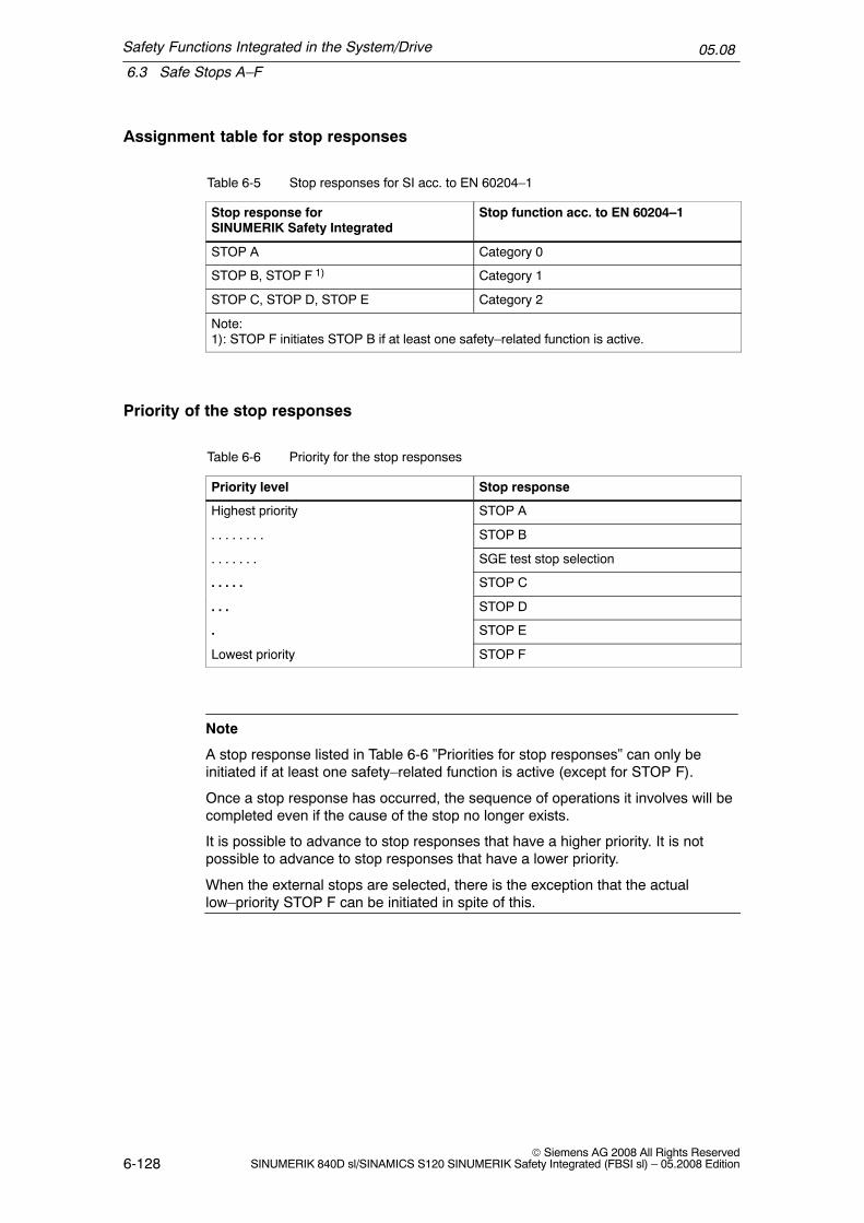
Safety Functions Integrated in the System/Drive
6.3 Safe Stops A–F
05.08
6-128© Siemens AG 2008 All Rights Reserved
SINUMERIK 840D sl/SINAMICS S120 SINUMERIK Safety Integrated (FBSI sl) – 05.2008 Edition
Assignment table for stop responses
Table 6-5 Stop responses for SI acc. to EN 60204–1
Stop response forSINUMERIK Safety Integrated
Stop function acc. to EN 60204–1
STOP A Category 0
STOP B, STOP F 1) Category 1
STOP C, STOP D, STOP E Category 2
Note:1): STOP F initiates STOP B if at least one safety–related function is active.
Priority of the stop responses
Table 6-6 Priority for the stop responses
Priority level Stop response
Highest priority STOP A
. . . . . . . . STOP B
. . . . . . . SGE test stop selection
. . . . . STOP C
. . . STOP D
. STOP E
Lowest priority STOP F
Note
A stop response listed in Table 6-6 ”Priorities for stop responses” can only beinitiated if at least one safety–related function is active (except for STOP F).
Once a stop response has occurred, the sequence of operations it involves will becompleted even if the cause of the stop no longer exists.
It is possible to advance to stop responses that have a higher priority. It is notpossible to advance to stop responses that have a lower priority.
When the external stops are selected, there is the exception that the actuallow–priority STOP F can be initiated in spite of this.

Safety Functions Integrated in the System/Drive
6.3 Safe Stops A–F
05.08
6-129© Siemens AG 2008 All Rights ReservedSINUMERIK 840D sl/SINAMICS S120 SINUMERIK Safety Integrated (FBSI sl) – 05.2008 Edition
Stop response sequence
If a stop response is initiated in the drive, a signal is sent to the NC that respondsby initiating the same stop response (two–channel safety). Likewise, if a stop re-sponse is initiated in the NC, the drive is automatically signaled and responds byrequesting the same stop response.This mechanism ensures that stop responses are managed with a high degree ofsafety.
External stops
Using this function, the user can stop the drive using SGEs.The drives can be brought to a standstill in the following ways:
� By canceling the drive pulses SGE ”deselect ext. STOP A”
� Braking with nset = 0 SGE ”deselect ext. STOP C”
� Braking along a path SGE ”deselect ext. STOP D”
� Initiate an ESR SGE ”deselect ext. STOP E”
Enabling and activating the function
The function ”external STOPs” is enabled and activated using the following ma-chine data:
� Enabling the functionMD 36901/parameter p9501: $MA_SAFE_FUNCTION_ENABLE/”SI motion, enable safety functions”Bit 0: Enable SBH/SG (see note)Bit 6: Enable external STOPsBit 4: Enable external STOP E
Note
� In addition to enabling the function ”external STOPs”, function SBH/SG mustalso be enabled as a minimum requirement.
� The external STOP E must be enabled with bit 4 = 1 in addition to bit 6 ”enableexternal STOPs”.
Configuring NCK–SGEs
for 840D sl:
MD 36977: $MA_SAFE_EXT_STOP_INPUT[n]:(input assignment, external stop request) with n = 0, 1, 2, 3.
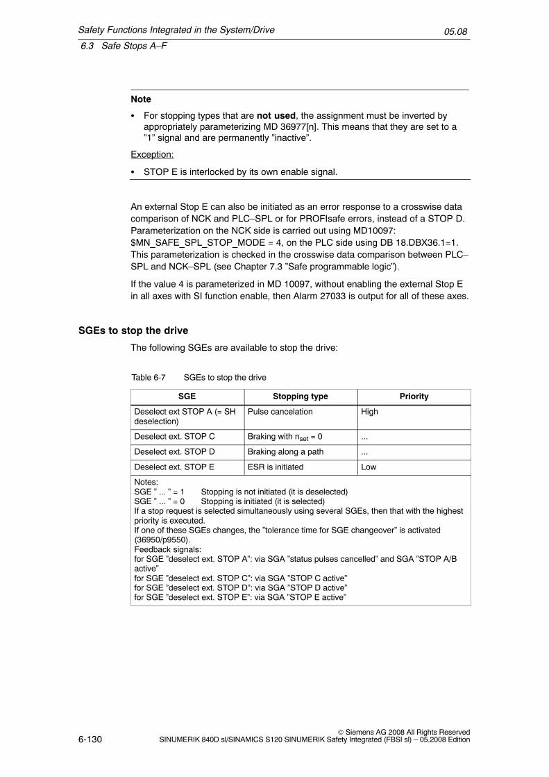
Safety Functions Integrated in the System/Drive
6.3 Safe Stops A–F
05.08
6-130© Siemens AG 2008 All Rights Reserved
SINUMERIK 840D sl/SINAMICS S120 SINUMERIK Safety Integrated (FBSI sl) – 05.2008 Edition
Note
� For stopping types that are not used, the assignment must be inverted byappropriately parameterizing MD 36977[n]. This means that they are set to a”1” signal and are permanently ”inactive”.
Exception:
� STOP E is interlocked by its own enable signal.
An external Stop E can also be initiated as an error response to a crosswise datacomparison of NCK and PLC–SPL or for PROFIsafe errors, instead of a STOP D.Parameterization on the NCK side is carried out using MD10097:$MN_SAFE_SPL_STOP_MODE = 4, on the PLC side using DB 18.DBX36.1=1.This parameterization is checked in the crosswise data comparison between PLC–SPL and NCK–SPL (see Chapter 7.3 ”Safe programmable logic”).
If the value 4 is parameterized in MD 10097, without enabling the external Stop Ein all axes with SI function enable, then Alarm 27033 is output for all of these axes.
SGEs to stop the drive
The following SGEs are available to stop the drive:
Table 6-7 SGEs to stop the drive
SGE Stopping type Priority
Deselect ext STOP A (= SHdeselection)
Pulse cancelation High
Deselect ext. STOP C Braking with nset = 0 ...
Deselect ext. STOP D Braking along a path ...
Deselect ext. STOP E ESR is initiated Low
Notes:SGE ” ... ” = 1 Stopping is not initiated (it is deselected)SGE ” ... ” = 0 Stopping is initiated (it is selected)If a stop request is selected simultaneously using several SGEs, then that with the highestpriority is executed.If one of these SGEs changes, the ”tolerance time for SGE changeover” is activated(36950/p9550).Feedback signals:for SGE ”deselect ext. STOP A”: via SGA ”status pulses cancelled” and SGA ”STOP A/Bactive”for SGE ”deselect ext. STOP C”: via SGA ”STOP C active”for SGE ”deselect ext. STOP D”: via SGA ”STOP D active”for SGE ”deselect ext. STOP E”: via SGA ”STOP E active”

Safety Functions Integrated in the System/Drive
6.3 Safe Stops A–F
05.08
6-131© Siemens AG 2008 All Rights ReservedSINUMERIK 840D sl/SINAMICS S120 SINUMERIK Safety Integrated (FBSI sl) – 05.2008 Edition
Note
� For external STOPs, alarms are not displayed. This means that the userhimself must configure the required message/signal.
Combinations for external STOPs
The following input bit combinations are obtained for the SGEs ”deselect ext.STOP A”, ”deselect ext. STOP C”, ”deselect ext. STOP D” and ”deselect ext.STOP E”:
Table 6-8 Input bit combinations
SGE
DeselectexternalSTOP E
DeselectexternalSTOP D
DeselectexternalSTOP C
DeselectexternalSTOP A
Description
x x x 0 ”Pulse cancellation” is initiated
x x 0 1 ”Braking with nset = 0” is initiated
x 0 1 1 ”Braking along a path” is initiated
0 1 1 1 ”ESR” is initiated
1 1 1 1 External STOPs are not selected
Acknowledging a stop request
After requesting a specific stop type via SGE, this sequence can be cancelled byone of the following events:
� Deselecting the stop request
� Selecting a stop request using an SGE with a higher priority
� A higher stop request (STOP A; B; C or D) with a higher priority is receivedfrom an internal monitoring function

Safety Functions Integrated in the System/Drive
6.3 Safe Stops A–F
05.08
6-132© Siemens AG 2008 All Rights Reserved
SINUMERIK 840D sl/SINAMICS S120 SINUMERIK Safety Integrated (FBSI sl) – 05.2008 Edition
Effects of the stop responses on other axes/spindles
If a stop response is initiated, then this has the following effects on all of the otheraxes in the same channel:
STOP E: Extended stopping and retraction is initiated
STOP D: Braking along a path
STOP C: IPO fast stop (braking at the current limit)
STOP A: IPO fast stop (braking at the current limit)
The effect on the other axes in the channel can be influenced using MD 36964:$MA_SAFE_IPO_STOP_GROUP. This allows, for example, the pulses of a spindleto be safely cancelled (using an external STOP A), in order that this spindle can bemanually turned and the axes can still be moved while being safely monitored.
STOP $MA_SAFE_IPO_STOP_GROUP = 0 $MA_SAFE_IPO_STOP_GROUP = 1
C Axes that interpolate with the involved axisbrake at the current limit. All other axesbrake along the parameterized brakingramp.
Axes that interpolate with the involved axisbrake at the current limit. All other axes donot brake.
D Axes/spindles brake along the path oralong the parameterized braking ramp.
Axes that interpolate with the involved axisbrake along the parameterized brakingramp. All other axes do not brake.
E ESR enabled and active:ESR is initiatedESR neither active nor enabled:After a delay time of max. 2 Ipo clock cycles, the behavior as described for STOP D isinitiated.
6.3.2 Description of STOP A
Action in the drive monitoring channel:Pulses are immediately cancelled using the internal signal ”cancel pulses”. In addi-tion, the pulses in the gating unit are cancelled by a software function.
Action in the NCK monitoring channel:the pulses are cancelled via the internal shutdown path of the NCK monitoringchannel
� Effect:The drive coasts to a standstill if no external braking mechanism such as anarmature short–circuit and/or holding brake is used. The axis–specific alarmresults in a mode group stop, i.e. as the result of the error in one axis, all axesand spindles in a mode group are stopped. Safe standstill becomes effective atthe end of STOP A.
� Alarm message for an internally initiated STOP A:The alarm message ”STOP A initiated” is displayed.

Safety Functions Integrated in the System/Drive
6.3 Safe Stops A–F
05.08
6-133© Siemens AG 2008 All Rights ReservedSINUMERIK 840D sl/SINAMICS S120 SINUMERIK Safety Integrated (FBSI sl) – 05.2008 Edition
� Acknowledgement for an internally initiated STOP A:An unintentional restart is prevented for STOP A. The error can only be ac-knowledged from the drive and control using a power on.
SGA STOP A/B activeThis signal indicates that STOP A/B is active.0 signal: STOP A/B is not active.1 signal: STOP A/B is active.
!Warning
If the ”safe standstill” function or ”STOP A” is activated, the motor can no longergenerate any torque. This is the reason that potentially hazardous motion canoccur, e.g. for the following:
� When an external force acts on the drive axes� Vertical and inclined axes without weight equalization� Axes that are moving (coasting down)� Direct drives with low friction and low self–locking� Notching torques (depending on the motor type, bearing design and friction
characteristics, up to half a pole pitch in a direction that cannot be predicted)
Possible hazards must be clearly identified using a risk analysis that must becarried out by the manufacturer. With an assessment, based on this risk analysis,it should be defined as to which additional measures are required, e.g. externalbrakes.
SGE deselect external STOP A
”Pulse cancellation” can be requested and executed using this SGE.The safe functions currently active (SG/SBH/SN/SE) are not influenced by thisSGE.If one of the currently active limits is violated, an appropriate alarm is initiated. Theassociated shutdown response cannot be activated because the pulses have al-ready been cancelled. As soon as the stop request is cancelled via the SGE ”dese-lect ext. STOP A” any queued shutdown responses become active.
If a stop request is active, SGA ”STOP A/B is active” is set in the same way as itwould be for an internally triggered STOP A.
MD 36977: $MA_SAFE_EXT_STOP_INPUT[0] is used to define the selection/deselection of the external brake request, in this case, ”deselect external STOP A”(SH, pulse cancellation).

Safety Functions Integrated in the System/Drive
6.3 Safe Stops A–F
05.08
6-134© Siemens AG 2008 All Rights Reserved
SINUMERIK 840D sl/SINAMICS S120 SINUMERIK Safety Integrated (FBSI sl) – 05.2008 Edition
6.3.3 Description of STOP B
Action in the drive monitoring channel:The drive is braked along the OFF3 ramp by entering a speed setpoint = 0. If thespeed setpoint falls below the value entered into p9560: ”SI motion, pulse cancella-tion shutdown speed”, or if the timer p9556: ”SI motion, delay time expired”, thenthe system automatically changes into a STOP A.
Action in the NCK monitoring channel:Analog to the drive, the control enters a speed setoint of 0 and when the value inMD 36960: $MA_SAFE_STANDSTILL_VELO_TOL is fallen below or after thetimer MD 36956: $MA_SAFE_PULSE_DISABLE_DELAY has expired, then a tran-sition is automatically made to STOP A.
If the timer in data 36956: $MA_SAFE_PULSE_DISABLE_DELAY or p 9556: ”SImotion pulse cancellation, delay time” is set to zero, then for a STOP B, thesystem immediately changes over to a STOP A.
The shutdown speed for the pulse cancellation is generally reached faster than thedelay time for the pulse cancellation.
� Effect:The drive is braked along the OFF3 ramp under closed–loop speed control andbrought to a safe standstill.
� Alarm message for an internally initiated STOP BThe alarm message ”STOP B initiated” is displayed.
� Alarm message for an internally initiated STOP B:An unintentional restart is prevented using a STOP A. The error can only beacknowledged from the drive and control using a power on.
SGA STOP A/B is activeThis signal indicates that STOP A/B is active.0 signal: STOP A/B is not active.1 signal: STOP A/B is active.

Safety Functions Integrated in the System/Drive
6.3 Safe Stops A–F
05.08
6-135© Siemens AG 2008 All Rights ReservedSINUMERIK 840D sl/SINAMICS S120 SINUMERIK Safety Integrated (FBSI sl) – 05.2008 Edition
RPM
a)
b)
STOP B STOP A
STOP ASTOP B
tSTOP B STOP A
a)b)
a) Shutdown time is reached before thepulse cancellation delay time expires
b) Shutdown time is reached after thepulse cancellation delay time expires
nact
Shutoff speed forpulse suppression
Delay time, pulsecancellation
Fig. 6-6 Transition from STOP B to STOP A
It is possible that the stop for the NCK becomes effective one safety monitoringclock cycle earlier than for the drive. This means that braking along the currentlimit can become effective before the OFF3 ramp of the drive becomes effective.In order to reduce the level of stress of the mechanical system of the machine (ifrequired) the braking torque can be reduced. To realize this, bit 4 ”Torque limitingactive in motoring/regenerating mode” can be set in parameter p1400 and parame-ter p1521 ”Torque limit lower/regenerative” can be set to the required lower torque.In this case, it should be noted that the braking distance (stopping distance) of theaxis is extended.
6.3.4 Description of STOP C
Action in the drive monitoring channel:The drive is braked along the STOP2 ramp in response to a speed setpoint input =0 and in parallel, the timer via parameter p9552: ”Transition time from STOP C toSBH” is started. The SBH function is automatically activated after the timer ex-pires.
Action in the NCK monitoring channel:Essentially the same as in the drive, the control specifies a zero speed setpointand the interface signal ”position controller active” (DB 31, ... DBX 61.5) of the as-sociated drive is set to zero.At the same time, the timer via MD 36952: $MA_SAFE_STOP_SWITCH_TIME_Cis started. The SBH function is automatically activated after the timer expires.
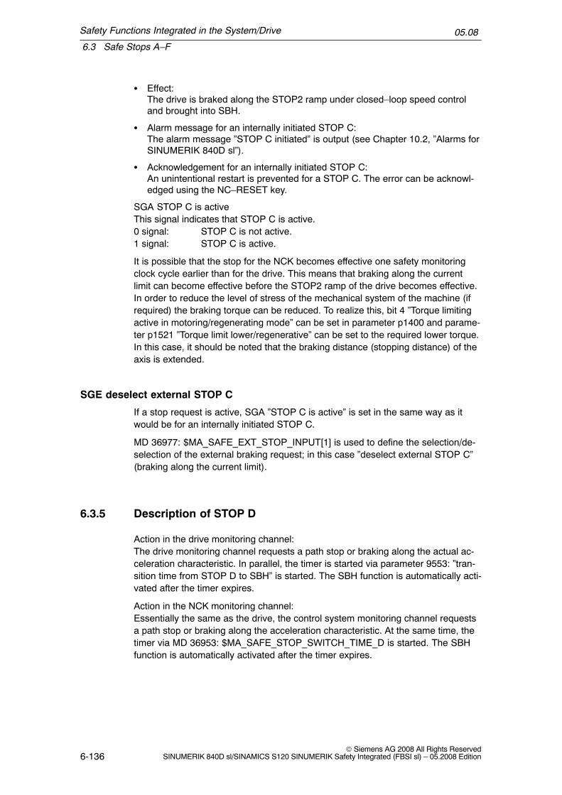
Safety Functions Integrated in the System/Drive
6.3 Safe Stops A–F
05.08
6-136© Siemens AG 2008 All Rights Reserved
SINUMERIK 840D sl/SINAMICS S120 SINUMERIK Safety Integrated (FBSI sl) – 05.2008 Edition
� Effect:The drive is braked along the STOP2 ramp under closed–loop speed controland brought into SBH.
� Alarm message for an internally initiated STOP C:The alarm message ”STOP C initiated” is output (see Chapter 10.2, ”Alarms forSINUMERIK 840D sl”).
� Acknowledgement for an internally initiated STOP C:An unintentional restart is prevented for a STOP C. The error can be acknowl-edged using the NC–RESET key.
SGA STOP C is activeThis signal indicates that STOP C is active.0 signal: STOP C is not active.1 signal: STOP C is active.
It is possible that the stop for the NCK becomes effective one safety monitoringclock cycle earlier than for the drive. This means that braking along the currentlimit can become effective before the STOP2 ramp of the drive becomes effective.In order to reduce the level of stress of the mechanical system of the machine (ifrequired) the braking torque can be reduced. To realize this, bit 4 ”Torque limitingactive in motoring/regenerating mode” can be set in parameter p1400 and parame-ter p1521 ”Torque limit lower/regenerative” can be set to the required lower torque.In this case, it should be noted that the braking distance (stopping distance) of theaxis is extended.
SGE deselect external STOP C
If a stop request is active, SGA ”STOP C is active” is set in the same way as itwould be for an internally initiated STOP C.
MD 36977: $MA_SAFE_EXT_STOP_INPUT[1] is used to define the selection/de-selection of the external braking request; in this case ”deselect external STOP C”(braking along the current limit).
6.3.5 Description of STOP D
Action in the drive monitoring channel:The drive monitoring channel requests a path stop or braking along the actual ac-celeration characteristic. In parallel, the timer is started via parameter 9553: ”tran-sition time from STOP D to SBH” is started. The SBH function is automatically acti-vated after the timer expires.
Action in the NCK monitoring channel:Essentially the same as the drive, the control system monitoring channel requestsa path stop or braking along the acceleration characteristic. At the same time, thetimer via MD 36953: $MA_SAFE_STOP_SWITCH_TIME_D is started. The SBHfunction is automatically activated after the timer expires.

Safety Functions Integrated in the System/Drive
6.3 Safe Stops A–F
05.08
6-137© Siemens AG 2008 All Rights ReservedSINUMERIK 840D sl/SINAMICS S120 SINUMERIK Safety Integrated (FBSI sl) – 05.2008 Edition
� Effect:The drive is braked in a group – including simultaneous axes – along the settraversing path. Endlessly rotating axes are braked at the acceleration limit. TheSBH function is automatically activated after the timer expires.
� Alarm message for an internally initiated STOP D:The alarm message ”STOP D initiated” is output.
� Acknowledgement for an internally initiated STOP D:An unintentional restart is prevented for STOP D. The error can be acknowl-edged using the NC–RESET key.
SGA STOP D is activeThis signal indicates that STOP D is active.0 signal: STOP D is not active.1 signal: STOP D is active.
SGE deselect external STOP D
If a stop request is active, SGA ”STOP D is active” is set in the same way as itwould be for an internally triggered STOP D.
MD 36977: $MA_SAFE_EXT_STOP_INPUT[2] is used to define the selection/de-selection of the external braking request, in this case ”deselect external STOP D”(path braking).
6.3.6 Description of STOP E
Action in the drive monitoring channel:The drive monitoring channel requests an extended stop and retract (ESR), con-trolled from the NC. At the same time, timer in parameter p9554: ”SI motion transi-tion time from STOP E to SBH” is started. The SBH function is automatically acti-vated after the timer expires.
Action in the NCK monitoring channel:An ESR is requested by the control monitoring channel. At the same time, timer inMD 36954: $MA_SAFE_STOP_SWITCH_TIME_E is started. The SBH function isautomatically activated after the timer expires.
� Effect:The extended stop and retract that have been configured are started.
� Alarm message:The alarm message ”STOP E initiated” is displayed.
� Acknowledgment:For STOP E, an unintentional restart is prevented. The error can be acknowl-edged using the NC–RESET key.
SGA STOP E is activeThis signal indicates that STOP E is active.0 signal: STOP E is not active.1 signal: STOP E is active.

Safety Functions Integrated in the System/Drive
6.3 Safe Stops A–F
05.08
6-138© Siemens AG 2008 All Rights Reserved
SINUMERIK 840D sl/SINAMICS S120 SINUMERIK Safety Integrated (FBSI sl) – 05.2008 Edition
The NC–controlled ESR is initiated by writing to the system variable$AC_ESR_TRIGGER=1 (also see /FB3/, M3 ”Axis coupling and ESR”). To obtainthe criteria for initiating, the following SI system variables are used:
$VA_STOPSI:Axial system variable that contains the present stop.For a value of 4, a Stop E is active for this axis.
$A_STOPESI:Global system variable that displays a value not equal to 0 to indicate that a Stop Eis active on one of the axes. This variable saves the user having to search throughall of the axes.
SGE deselect external STOP E
When a stop request is active, the SGA ”STOP E is active” is set.
MD 36977: $MA_SAFE_EXT_STOP_INPUT[3] defines the selection/deselection ofthe external braking request, in this case ”deselect external STOP E” (extendedstopping and retraction plus path braking).
Note
STOP E only produces a different response than STOP D if the user hasconfigured the ESR function – extended stop and retract – and initiation of theESR is programmed depending on $VA_STOPSI or $A_STOPESI.If ESR is not active, the STOP E behaves like a STOP D. However, if the ESRconfiguration is incorrect, there is a delay of up to 2 IPO cycles compared toSTOP D until the braking operation is initiated. Possible causes:
� The initiation of the ESR as static synchronous action does not take intoaccount the system variables $VA_STOPSI or $A_STOPESI.
� ESR is neither parameterized nor enabled.
� For individual PLC controlled axes, only the axis–specific ESR is used via$AA_ESR_TRIGGER. This trigger may be used in addition to thechannel–specific trigger.
For other incorrect ESR programming, a delay by the time entered in$MC_ESR_DELAY_TIME1 and $MC_ESR_DELAY_TIME2 is possible. After thesetimes have expired, braking is initiated at the current limit. Possible cause:
� The retraction position cannot be reached within the specified time.

Safety Functions Integrated in the System/Drive
6.3 Safe Stops A–F
05.08
6-139© Siemens AG 2008 All Rights ReservedSINUMERIK 840D sl/SINAMICS S120 SINUMERIK Safety Integrated (FBSI sl) – 05.2008 Edition
6.3.7 Description of STOP F
The STOP F response is permanently assigned to the error handling (e.g. thecrosswise result and data comparison, detecting communication and encoderfaults).
If such as fault/error state is detected, then the following responses are triggered.
Response, if no safety functions are active:
Faults/errors are also detected if none of the safety–related functions are active(safety functions are SBH, SG, SE, SN). The saved message ”defect in a monitor-ing channel” is output on both the drive and control sides and can only be acknowl-edged using the NC–RESET key. The message does not interrupt machining.A system restart is prevented by an internal NC start/traversing inhibit function.Faults/errors are detected in the drive and control systems.
Response if one safety function is active:
Faults/errors are detected and a STOP B/A response is initiated in the drive andcontrol system (see description of STOP B). The error can only be acknowledgedfrom the drive and control using a power on.Exception: If an internal STOP C/D/E is already present, because STOP F has alower priority (see Chapter 6.3.1, Section ”Priority of the stop responses”).
� Alarm message:Alarms 27001 ”defect in a monitoring channel” and C01711 ”SI motion defect ina monitoring channel” are displayed.For further diagnostics, for Alarm 27001, a fine error coding is displayed in thealarm line. The fine coding for the drive alarm can be found in r9725 ”SI motiondiagnostics for STOP F”.The significance of the error code is provided in Chapter10.2 under Alarm27001 ”Defect in a monitoring channel”.
A delay time before STOP B is initiated can be parameterized using MD 36955$MA_SAFE_STOP_SWITCH_TIME_F. During this time, the machine manufac-turer can initiate an NC controlled response, e.g. ESR. After this time has expired,the involved axis is braked with STOP B. This is also true if, in the meantime, astop with a higher priority than STOP F (STOP E, D, C) is present. The systemvariables $VA_XFAULTSI and $A_XFAULTSI, bit 1 can be used to detect whethera STOP F was initiated that is then followed by a STOP B. In the delay time up tothe STOP B, an ESR or braking along the programmed path can be initiated (e.g.by writing to $AC_ESR_TRIGGER or initiating an external STOP D).During the delay time up to initiating STOP B, additional, non–safety–related moni-toring functions can already result in other braking responses. A STOP D or theinitiation of ESR can be influenced due to harder braking responses of the drive(the same as e.g. the configured braking response when an encoder fails).

Safety Functions Integrated in the System/Drive
6.3 Safe Stops A–F
05.08
6-140© Siemens AG 2008 All Rights Reserved
SINUMERIK 840D sl/SINAMICS S120 SINUMERIK Safety Integrated (FBSI sl) – 05.2008 Edition
!Warning
If an internal or external fault occurs, none or only some of the parameterizedsafety functions are available during the STOP F response triggered by the fault.This must be carefully taken into account when parameterizing the delay timebetween STOP F and STOP B (MD 36955/p9555) and must be taken into accountin the risk analysis performed by the machine manufacturer. This is especially truefor vertical axes.
Note
A delay time between STOP F and STOP B should only be set, if, during this time,an alternative response is initiated by evaluating the system variables$VA_XFAULTSI and $A_XFAULTSI.
Further, when using the delay time, a monitoring function should always be active– also in the automatic mode (e.g. SE, SN, SG with high limit switch). Forexample, if the SBH monitoring function is only active on the drive side, forexample because of the (single–channel) failure of a door switch, then althoughthis results in a STOP F, the STOP F –> STOP B delay time on the NCK side isnot started if previously no monitoring function was active. This means that in thiscase, the drive responds with a STOP B (however this is also initiated in the NCKdue to the exchange of the stop responses), but this is not displayed in the NCKvariables $VA_XFAULTSI and $A_XFAULTSI.The appropriate monitoring functions of the drive (e.g. when SBH is selected) arealso executed instantaneously without any delay.
Example 1 – delaying the transition from STOP F to STOP B:
The speed characteristics of an axis for parameterized stopping are shown in Fig.6-7. In this case, the axis should continue 500 ms and then brake along the para-meterized ramp. A delay time of 2.5 s is selected until STOP B is initiated($MA_SAFE_STOP_SWITCH_TIME_F).
Continue to traverse (ESR)
t1 t2 t3
v
t
Braking along a ramp =stopping (ESR)
Fig. 6-7 Velocity characteristic of an SI axis when stopping with STOP F

Safety Functions Integrated in the System/Drive
6.3 Safe Stops A–F
05.08
6-141© Siemens AG 2008 All Rights ReservedSINUMERIK 840D sl/SINAMICS S120 SINUMERIK Safety Integrated (FBSI sl) – 05.2008 Edition
The following actions take place at the following instants in time:
t1:STOP F occurs, ESR is startedt2:500 ms after t1, braking starts along the parameterized rampt3:STOP B is initiated 2.5 s after t1. The axis is already stationary at this time, whichmeans that the pulses can be immediately cancelled.
Example 2 – delaying the transition from STOP F to STOP B
The same parameterization as in Example 1 is shown in Fig. 6-8. However, when aSTOP F occurs, no monitoring function is active. At instant in time t2, a monitoringfunction is activated. ESR is only started if there is a STOP F with active monitor-ing function.
Continue to traverse (ESR)
t1 t2 t3
v
tt4
Braking along a ramp =stopping (ESR)
Fig. 6-8 Velocity characteristic of an SI axis when stopping with STOP F
The following actions take place at the following instants in time:
t1:STOP F occurs, no responset2:At any time after t1, a monitoring function is activated. At this instant in time, thetransition to a STOP B is started and bits 1 in $A_XFAULTSI and $VA_XFAULTSIof this axis are set.t3:500 ms after t2, braking starts along the parameterized rampt4:STOP B is initiated 2.5 s after t2. The axis is already stationary at this time, whichmeans that the pulses can be immediately cancelled.

Safety Functions Integrated in the System/Drive
6.3 Safe Stops A–F
05.08
6-142© Siemens AG 2008 All Rights Reserved
SINUMERIK 840D sl/SINAMICS S120 SINUMERIK Safety Integrated (FBSI sl) – 05.2008 Edition
6.3.8 Forced checking procedure of the external STOPs
The following applies for the test stop of external STOPs:All stop SGEs that are used are switched one after the other in each channel andthe positive response evaluated using the associated SGA ”STOP x is active”.
Note
Only the enabled and activated external standstill functions have to be tested.
SGA ”STOP A/B is active”SGE ”deselect ext. STOP A”
SGA ”STOP C is active”
SGE ”deselect ext. STOP C”
SGE ”deselect ext. STOP D”
SGA ”STOP D is active”
SGE ”deselect ext. STOP E”
SGA ”STOP E is active”
Fig. 6-9 Sequence of the test stop for external STOPs. Example: External STOPs A, C, D, E are used

Safety Functions Integrated in the System/Drive
6.3 Safe Stops A–F
05.08
6-143© Siemens AG 2008 All Rights ReservedSINUMERIK 840D sl/SINAMICS S120 SINUMERIK Safety Integrated (FBSI sl) – 05.2008 Edition
Which SGEs/SGAs are required for the test stop of external STOPs?
The following SGEs/SGAs can be used to perform the test stop for externalSTOPs:
Table 6-9 SGEs/SGAs for the test stop, external STOPs
NCK moni-toring chan-nel
NCK–SGE ”deselect ext. STOP A”NCK–SGA ”STOP A/B is active”
NCK–SGE ”deselect ext. STOP C”NCK–SGA ”STOP C is active”
NCK–SGE ”deselect ext. STOP D”NCK–SGA ”STOP D is active”
NCK–SGE ”deselect ext. STOP E”NCK–SGA ”STOP E is active”
Drive moni-toring chan-nel
PLC–SGE ”deselect ext. STOP A”PLC–SGA ”STOP A/B is active”
PLC–SGE ”deselect ext. STOP C”PLC–SGA ”STOP C is active”
PLC–SGE ”deselect ext. STOP D”PLC–SGA ”STOP D is active”
PLC–SGE ”deselect ext. STOP E”PLC–SGA ”STOP E is active”

Safety Functions Integrated in the System/Drive
6.4 Safe acceleration monitoring (SBR)
05.08
6-144© Siemens AG 2008 All Rights Reserved
SINUMERIK 840D sl/SINAMICS S120 SINUMERIK Safety Integrated (FBSI sl) – 05.2008 Edition
6.4 Safe acceleration monitoring (SBR)
Description
Using this function, for STOPs B and C the system monitors as to whether thedrive speed increases.
Features
The most important features include:
� Fastest possible detection if the axis starts to re–accelerate when braking
� SBR is automatically activated, when a STOP B or C has been initiated
� STOP A is initiated when SBR responds
Activating the SBR
When a STOP B or C is initiated, the actual speed plus the speed tolerance, de-fined in the machine data/parameter, is activated as the speed limit. When the ac-tual speed reduces, then this speed limit is correspondingly corrected; however, foran increased speed, it is not changed. If the drive speed exceeds the actual speedlimit then a STOP A is initiated. If the axis starts to re–accelerate while braking,this is detected as quickly as possible and prevented.
Machine data/parameters for the SBR speed tolerance:
for 840D sl:MD 36948: $MA_SAFE_STOP_VELO_TOL
for SINAMICS S120:p9548: SI motion SBR actual speed tolerance (Control Unit)The speed limit is corrected until the speed, defined in the following machine data,is undershot (fallen below). After that, the limit value of the SBR monitoring is fro-zen to the value in MD/parameter 36946/p9546 plus the value in MD/parameter36948/p9548.
for 840D sl:MD 36946: $MA_SAFE_VELO_X (speed limit nx)
for SINAMICS S120:p9546: SI motion SSM (SGA n < nx) speed limit n_x (CU)

Safety Functions Integrated in the System/Drive
6.4 Safe acceleration monitoring (SBR)
05.08
6-145© Siemens AG 2008 All Rights ReservedSINUMERIK 840D sl/SINAMICS S120 SINUMERIK Safety Integrated (FBSI sl) – 05.2008 Edition
n
nx
t
STOP B/C initiated
nact
Stopping limit valueSpeed tolerance
Fig. 6-10 Characteristic of the stopping limit value for SBR
Calculating the SBR tolerance of the actual speed
The following applies when parameterizing the SBR tolerance:
The possible speed increase after initiating a STOP B/C is obtained from the effec-tive acceleration a and the duration of the acceleration phase. The accelerationphase lasts from one monitoring clock cycle ÜT (delay from detecting a STOP B/Cuntil nset = 0):
SBR toleranceActual speed for SBR = acceleration * acceleration duration
The following setting rules apply:
For a linear axis:SBR tolerance [mm/min] = a [m/s2] * ÜT [s] * 1000 [mm/m] * 60 [s/min]
For rotary axis/spindle:SBR tolerance [rev/min] = a [rev/s2] * ÜT [s] * 60 [s/min]
The following machine data should be taken into account when determining theacceleration:
MD 32300: MAX_AX_ACCELMD 35200: GEAR_STEP_SPEEDCTRL_ACCELMD 35210: GEAR_STEP_POSCTRL_ACCELMD 35410: SPIND_OSCILL_ACCEL
Recommendation:The value entered for the SBR tolerance should be approx. 20% higher than thecalculated value.
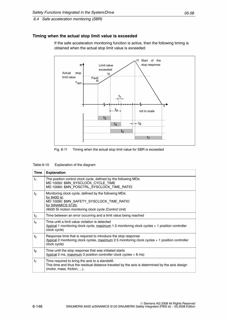
Safety Functions Integrated in the System/Drive
6.4 Safe acceleration monitoring (SBR)
05.08
6-146© Siemens AG 2008 All Rights Reserved
SINUMERIK 840D sl/SINAMICS S120 SINUMERIK Safety Integrated (FBSI sl) – 05.2008 Edition
Timing when the actual stop limit value is exceeded
If the safe acceleration monitoring function is active, then the following timing isobtained when the actual stop limit value is exceeded:
n
nacta)
b)
c)
t
Fault
Limit valueexceeded
Start of thestop response
not to scale
t6t4
t2
t5
t1
t3
t7
Actual stoplimit value
Fig. 6-11 Timing when the actual stop limit value for SBR is exceeded
Table 6-10 Explanation of the diagram
Time Explanation
t1 The position control clock cycle, defined by the following MDs:MD 10050: $MN_SYSCLOCK_CYCLE_TIMEMD 10060: $MN_POSCTRL_SYSCLOCK_TIME_RATIO
t2 Monitoring clock cycle, defined by the following MDs:for 840D sl:MD 10090: $MN_SAFETY_SYSCLOCK_TIME_RATIOfor SINAMICS S120:r9500 SI motion monitoring clock cycle (Control Unit)
t3 Time between an error occurring and a limit value being reached
t4 Time until a limit value violation is detected(typical 1 monitoring clock cycle, maximum 1.5 monitoring clock cycles + 1 position controllerclock cycle)
t5 Response time that is required to introduce the stop response(typical 2 monitoring clock cycles, maximum 2.5 monitoring clock cycles + 1 position controllerclock cycle)
t6 Time until the stop response that was initiated starts(typical 2 ms, maximum 3 position controller clock cycles + 8 ms)
t7 Time required to bring the axis to a standstill.This time and thus the residual distance traveled by the axis is determined by the axis design(motor, mass, friction, ...).

Safety Functions Integrated in the System/Drive
6.4 Safe acceleration monitoring (SBR)
05.08
6-147© Siemens AG 2008 All Rights ReservedSINUMERIK 840D sl/SINAMICS S120 SINUMERIK Safety Integrated (FBSI sl) – 05.2008 Edition
Notice
During ”normal” operation, speed overshoot should not unintentionally initiate theSBR. Speed overshoot should therefore be checked by making the appropriatemeasurements.
!Warning
If the ”safe standstill” function or ”STOP A” is activated, the motor can no longergenerate any torque. This is the reason that potentially hazardous motion canoccur, e.g. for the following:
� When an external force acts on the drive axes� Vertical and inclined axes without weight equalization� Axes that are moving (coasting down)� Direct drives with low friction and low self–locking� Notching torques (depending on the motor type, bearing design and friction
characteristics, up to half a pole pitch in a direction that cannot be predicted)
Possible hazards must be clearly identified using a risk analysis that must becarried out by the manufacturer. With an assessment, based on this risk analysis,it should be defined as to which additional measures are required, e.g. externalbrakes.

Safety Functions Integrated in the System/Drive
6.5 Safely reduced speed (SG)
05.08
6-148© Siemens AG 2008 All Rights Reserved
SINUMERIK 840D sl/SINAMICS S120 SINUMERIK Safety Integrated (FBSI sl) – 05.2008 Edition
6.5 Safely reduced speed (SG)
Description
The purpose of the SG (safely reduced speed) function is to safely monitor theload–side speed of an axis/spindle.The actual speed of the axis/spindle is cyclically compared in the monitoring clockcycle with the speed limit value selected using SGEs. The speed limit values aredefined in the following machine data/parameters:
for 840D sl:MD 36931: $MA_SAFE_VELO_LIMIT[n]
for SINAMICS S120:p9531: SI motion SLS (SG) limits (Control Unit)
The speed limit values for SG1, SG2, SG3 or SG4 allow various applications/oper-ating states on the machine to be monitored. The safely reduced speed functioncan therefore be used to implement protective measures for the operating person-nel and machine in the setting–up mode or also in automatic operation.
!Warning
For control gears, it is important to select the correct gear ratio!
Features
The features of the SG function are as follows:
� Load–side speed limit values are safely monitored
� Monitoring limit values are adapted to various operating states (e.g. test,setting–up, automatic modes)
� Configurable stop response when the SG responds
Prerequisites
The following prerequisites must be fulfilled (see Chapter 3.1, ”System prerequi-sites”):
� The option and functions must be enabled in the axis–specific machine data
� The SGEs ”SBH/SG deselection” and ”SBH deselection” must be configured

Safety Functions Integrated in the System/Drive
6.5 Safely reduced speed (SG)
05.08
6-149© Siemens AG 2008 All Rights ReservedSINUMERIK 840D sl/SINAMICS S120 SINUMERIK Safety Integrated (FBSI sl) – 05.2008 Edition
Specifying velocities and speeds
The requirements regarding speeds and velocities that are stipulated for individualprocesses (milling, turning, grinding, etc.) vary depending on the different CStandards. For example, the following could be specified for the setting–up mode:”Safely reduced speed” with 2 m/min for feed drives and50 RPM for spindle drives or standstill within 2 revolutions.
The machine manufacturer must parameterize SI in such a way as to ensure fullcompliance with the EC Machinery Directive. The relevant standards provide thenecessary guidelines and support.
Quantities that influence the parameterization include, e.g. the drive dynamic re-sponse, the set parameters with their delay times, electrical and mechanical gearratios and all of the mechanical properties and characteristics. The interrelation-ships between the drive dynamic response and internal delay times of SI areshown in Fig. 6-13 ”Timing when exceeding the limit value for SG”.
6.5.1 Speed monitoring, encoder limit frequency
When SBH/SG is active in a configuration with a 1–encoder, the speed is moni-tored to ensure that it does not exceed a maximum encoder limit frequency. Anappropriate alarm is output if this limit is exceeded.
Encoder limit frequency
The encoder limit frequency is 500 kHz. When the encoder limit frequency in SG isexceeded, the SG–specific parameterized stop is initiated.

Safety Functions Integrated in the System/Drive
6.5 Safely reduced speed (SG)
05.08
6-150© Siemens AG 2008 All Rights Reserved
SINUMERIK 840D sl/SINAMICS S120 SINUMERIK Safety Integrated (FBSI sl) – 05.2008 Edition
6.5.2 Selecting/deselecting safely reduced speed
Selecting SG
The following SGEs are used to select SG:
Table 6-11 Selecting/deselecting SG
SGE
SBH/SG deselection
SBHdeselection
Description
= 1 x SBH and SG are deselected
= 0 = 0 SBH is selected(see Chapter 6.2, ”Safe operating stop (SBH)”
= 0 = 1 SG is selected
Note: x –> Any signal state
Note
The actual status of the function is displayed using the SGA ”SBH/SG active” andSGA ”SBH active”.
Before activating the SG function it must be ensured that the speed of theaxis/spindle is lower than the selected speed limit value. If it is higher, an alarm isgenerated that causes the drive to be shut down.
The SGEs and SGAs are described in Chapter 7.1 ”Safety–related input/outputsignals (SGE/SGA)”.
Selecting speed limit values
The maximum permissible speed of an axis/spindle in the setting–up mode is de-fined for individual machine types in the C Standards (product standards). The ma-chine manufacturer is responsible for ensuring that the correct speed limit value isselected depending on the operating mode and the application.
The required speed limit is selected as follows by combining the following SGEs:

Safety Functions Integrated in the System/Drive
6.5 Safely reduced speed (SG)
05.08
6-151© Siemens AG 2008 All Rights ReservedSINUMERIK 840D sl/SINAMICS S120 SINUMERIK Safety Integrated (FBSI sl) – 05.2008 Edition
Table 6-12 Selecting speed limit values for SGs
SGE
SG selectionBit 1
SG selectionBit 0
Description
= 0 = 0 Speed limit value for SG1 active
= 0 = 1 Speed limit value active for SG2 1)
= 1 = 0 Speed limit value for SG3 active
= 1 = 1 Speed limit value active for SG4 1)
Note:1) The SG limit values SG2 and SG4 can be finely graduated using the SG override (seeChapter 6.5.4, ”Override for safely reduced speed”.The active SG stage is displayed using SGA ”SGA active bit 0” and ”SGA active bit 1”.
Changing–over the speed limit values
A changeover from a lower to a higher speed limit value takes effect instanta-neously without any delay.
When changing–over from a higher to a lower limit value, then a delay time isstarted that is parameterized using the machine data(refer to Figure 6-12, ”Timing when changing–over from a higher to a lower speedlimit”).
for 840D sl:MD 36951: $MA_SAFE_VELO_SWITCH_DELAY
for SINAMICS S120:p9551: SI motion SLS (SG) changeover delay time (Control Unit) /
The axis/spindle must be braked sufficiently during the delay time so that it hasreached the reduced speed that is below the new limit value when the delay timeexpires. However, if the actual speed is higher than the new limit value when thetime has expired, an appropriate alarm is output with the configurable stop re-sponse.
Safety Functions Integrated in the System/Drive
6.5 Safely reduced speed (SG)
05.08
6-152© Siemens AG 2008 All Rights Reserved
SINUMERIK 840D sl/SINAMICS S120 SINUMERIK Safety Integrated (FBSI sl) – 05.2008 Edition
SG1V1
SG2V2
SG1 is active SG2 is active
Braking time
Timer running
v
t
a) Braking is started
SGEsfor SG1
SGEsfor SG2
Delay time, speed changeover
Fig. 6-12 Timing when changing–over from a higher to a lower speed limit
Deselecting SG
The SG function can be deselected at any speed by activating the SGE ”SBH/SGdeselection”.
!Warning
The delay time must also be selected as a function of the distance to thehazardous location. The speeds to be taken into account (speed at whichhands/arms are moved to appropriately arrange protective devices/guards) arespecified in Standard DIN EN 999.

Safety Functions Integrated in the System/Drive
6.5 Safely reduced speed (SG)
05.08
6-153© Siemens AG 2008 All Rights ReservedSINUMERIK 840D sl/SINAMICS S120 SINUMERIK Safety Integrated (FBSI sl) – 05.2008 Edition
6.5.3 Effects when the limit value is exceeded for SG
Configurable stop response
When the selected speed limit value is violated, a stop response configured in thefollowing machine data/parameters is generated:
for 840D sl:
MD 36961: $MA_SAFE_VELO_STOP_MODEMD 36963: $MA_SAFE_VELO_STOP_REACTION[n]
for SINAMICS S120:
p9561: SI motion SLS (SG) stop response (Control Unit)p9563[0...3]: SI motion SLS (SG)–specific stop response (Control Unit)
Note
� An alarm is displayed (for 840D sl: 27011, for SINAMICS S120: F01714). Afterthe cause of the fault has been removed, the alarm can be acknowledged withRESET. The monitoring function is then again active.
� Depending on the selected monitoring clock cycle, the dynamic drives maycause a brief increase in speed on the monitored axis/spindle before the stopresponse sequence starts.
� For traversing modes which use a transformation with singularity points (e.g.5–axis transformation and TRANSMIT), relatively high axial speeds occur atthese points. These speeds can initiate stop responses even though theCartesian motion of the tool center point (TCP) is below the selected speedlimit value.The monitoring functions provided by SI are basically axis–specific. This meansthat it is not possible to directly monitor the TCP.

Safety Functions Integrated in the System/Drive
6.5 Safely reduced speed (SG)
05.08
6-154© Siemens AG 2008 All Rights Reserved
SINUMERIK 840D sl/SINAMICS S120 SINUMERIK Safety Integrated (FBSI sl) – 05.2008 Edition
Timing when the limit value is exceeded
When the safely reduced speed function is active, then the timing is as followswhen the limit value is violated:
n
nacta)
b)
c)
SG
t
Fault
Limit valueexceeded
Start of thestop response
not to scale
t6t4
t2
t5
t1
t3
t7
Fig. 6-13 Timing when the limit value is exceeded for SG
Table 6-13 Explanation of the diagram
Time Explanation
t1 The position control clock cycle, defined by the following MDs:MD 10050: $MN_SYSCLOCK_CYCLE_TIMEMD 10060: $MN_POSCTRL_SYSCLOCK_TIME_RATIO
t2 Monitoring clock cycle, defined by the following MDs:for 840D sl:MD 10090: $MN_SAFETY_SYSCLOCK_TIME_RATIOfor SINAMICS S120:r9500 SI motion monitoring clock cycle (Control Unit)
t3 Time between an error occurring and a limit value being reached
t4 Time until a limit value violation is detected(typical 1 monitoring clock cycle, maximum 1.5 monitoring clock cycles + 1 position controllerclock cycle)
t5 Response time required to initiate the configured stop response(typical 2 monitoring clock cycles, maximum 2.5 monitoring clock cycles + 1 position controllerclock cycle)
t6 Time until the stop response that was initiated starts(STOP A: typical 2 ms, maximum 3 position controller clock cycles + 8 ms)(STOP B/C: typical 2 position controller clock cycles, maximum 2 position controller clock cycles)(STOP D/E: typical 2 interpolation clock cycles, maximum 2 interpolation clock cycles + 2 moni-toring clock cycles)

Safety Functions Integrated in the System/Drive
6.5 Safely reduced speed (SG)
05.08
6-155© Siemens AG 2008 All Rights ReservedSINUMERIK 840D sl/SINAMICS S120 SINUMERIK Safety Integrated (FBSI sl) – 05.2008 Edition
Table 6-13 Explanation of the diagram
Time Explanation
t7 Time required to bring the axis to a standstill.This time and thus the residual distance traveled by the axis is determined by the axis design(motor, mass, friction, ...) and the configured stop response (STOP C is faster than STOP D).
Note:Each axis must be measured during commissioning (start–up) to determine the distance that it travelsbetween the limit switch being violated and it coming to a standstill.
Configurable SG specific stop responses
Using the configurable SG–specific stop response, a suitable braking behavior canbe set for every SG stage in–line with the application when the particular speedlimit value is exceeded.
For example, when:SETTING–UP, the SG stage SG2 can be active with the configured stop responseSTOP C andin the AUTOMATIC mode, the SG stage SG4 with the configured stop responseSTOP D.
Activating
The function is active if the MD/parameter 36961/p9561:$MA_SAFE_VELO_STOP_MODE = 5 / SI motion SLS (SG) stop response (Con-trol Unit) = 5.
Setting the configurable SG–specific stop responses
The SG–specific stop responses can be set using the following machine data:
for 840D sl:MD 36963: $MA_SAFE_VELO_STOP_REACTION[n]
for SINAMICS S120:p9563[0...3] SI motion SLS(SG)–specific stop response (Control Unit)
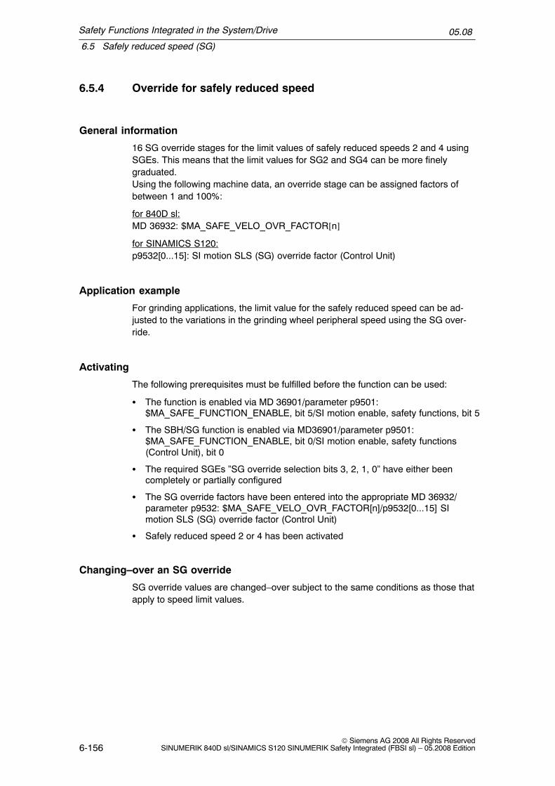
Safety Functions Integrated in the System/Drive
6.5 Safely reduced speed (SG)
05.08
6-156© Siemens AG 2008 All Rights Reserved
SINUMERIK 840D sl/SINAMICS S120 SINUMERIK Safety Integrated (FBSI sl) – 05.2008 Edition
6.5.4 Override for safely reduced speed
General information
16 SG override stages for the limit values of safely reduced speeds 2 and 4 usingSGEs. This means that the limit values for SG2 and SG4 can be more finelygraduated.Using the following machine data, an override stage can be assigned factors ofbetween 1 and 100%:
for 840D sl:MD 36932: $MA_SAFE_VELO_OVR_FACTOR[n]
for SINAMICS S120:p9532[0...15]: SI motion SLS (SG) override factor (Control Unit)
Application example
For grinding applications, the limit value for the safely reduced speed can be ad-justed to the variations in the grinding wheel peripheral speed using the SG over-ride.
Activating
The following prerequisites must be fulfilled before the function can be used:
� The function is enabled via MD 36901/parameter p9501:$MA_SAFE_FUNCTION_ENABLE, bit 5/SI motion enable, safety functions, bit 5
� The SBH/SG function is enabled via MD36901/parameter p9501:$MA_SAFE_FUNCTION_ENABLE, bit 0/SI motion enable, safety functions(Control Unit), bit 0
� The required SGEs ”SG override selection bits 3, 2, 1, 0” have either beencompletely or partially configured
� The SG override factors have been entered into the appropriate MD 36932/parameter p9532: $MA_SAFE_VELO_OVR_FACTOR[n]/p9532[0...15] SImotion SLS (SG) override factor (Control Unit)
� Safely reduced speed 2 or 4 has been activated
Changing–over an SG override
SG override values are changed–over subject to the same conditions as those thatapply to speed limit values.
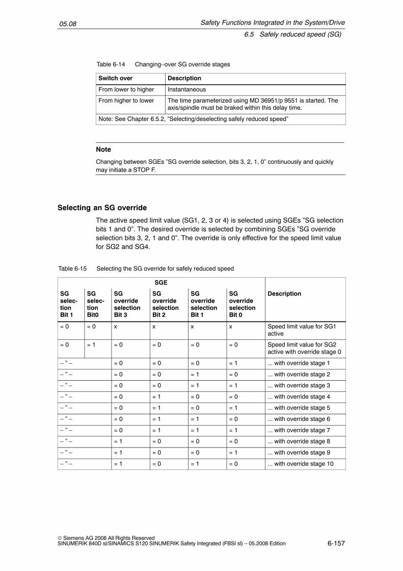
Safety Functions Integrated in the System/Drive
6.5 Safely reduced speed (SG)
05.08
6-157© Siemens AG 2008 All Rights ReservedSINUMERIK 840D sl/SINAMICS S120 SINUMERIK Safety Integrated (FBSI sl) – 05.2008 Edition
Table 6-14 Changing–over SG override stages
Switch over Description
From lower to higher Instantaneous
From higher to lower The time parameterized using MD 36951/p 9551 is started. Theaxis/spindle must be braked within this delay time.
Note: See Chapter 6.5.2, ”Selecting/deselecting safely reduced speed”
Note
Changing between SGEs ”SG override selection, bits 3, 2, 1, 0” continuously and quicklymay initiate a STOP F.
Selecting an SG override
The active speed limit value (SG1, 2, 3 or 4) is selected using SGEs ”SG selectionbits 1 and 0”. The desired override is selected by combining SGEs ”SG overrideselection bits 3, 2, 1 and 0”. The override is only effective for the speed limit valuefor SG2 and SG4.
Table 6-15 Selecting the SG override for safely reduced speed
SGE
SGselec-tionBit 1
SGselec-tionBit0
SGoverrideselectionBit 3
SGoverrideselectionBit 2
SGoverrideselectionBit 1
SGoverrideselectionBit 0
Description
= 0 = 0 x x x x Speed limit value for SG1active
= 0 = 1 = 0 = 0 = 0 = 0 Speed limit value for SG2active with override stage 0
– ” – = 0 = 0 = 0 = 1 ... with override stage 1
– ” – = 0 = 0 = 1 = 0 ... with override stage 2
– ” – = 0 = 0 = 1 = 1 ... with override stage 3
– ” – = 0 = 1 = 0 = 0 ... with override stage 4
– ” – = 0 = 1 = 0 = 1 ... with override stage 5
– ” – = 0 = 1 = 1 = 0 ... with override stage 6
– ” – = 0 = 1 = 1 = 1 ... with override stage 7
– ” – = 1 = 0 = 0 = 0 ... with override stage 8
– ” – = 1 = 0 = 0 = 1 ... with override stage 9
– ” – = 1 = 0 = 1 = 0 ... with override stage 10

Safety Functions Integrated in the System/Drive
6.5 Safely reduced speed (SG)
05.08
6-158© Siemens AG 2008 All Rights Reserved
SINUMERIK 840D sl/SINAMICS S120 SINUMERIK Safety Integrated (FBSI sl) – 05.2008 Edition
Table 6-15 Selecting the SG override for safely reduced speed
SGselec-tionBit 1
DescriptionSGoverrideselectionBit 0
SGoverrideselectionBit 1
SGoverrideselectionBit 2
SGoverrideselectionBit 3
SGselec-tionBit0
– ” – = 1 = 0 = 1 = 1 ... with override stage 11
– ” – = 1 = 1 = 0 = 0 ... with override stage 12
– ” – = 1 = 1 = 0 = 1 ... with override stage 13
– ” – = 1 = 1 = 1 = 0 ... with override stage 14
– ” – = 1 = 1 = 1 = 1 ... with override stage 15
= 1 = 0 x x x x Speed limit value for SG3active
= 1 = 1 = 0 = 0 = 0 = 0 Speed limit value for SG4active with override stage 0
– ” – = 0 = 0 = 0 = 1 ... with override stage 1
– ” – = 0 = 0 = 1 = 0 ... with override stage 2
– ” – = 0 = 0 = 1 = 1 ... with override stage 3
– ” – = 0 = 1 = 0 = 0 ... with override stage 4
– ” – = 0 = 1 = 0 = 1 ... with override stage 5
– ” – = 0 = 1 = 1 = 0 ... with override stage 6
– ” – = 0 = 1 = 1 = 1 ... with override stage 7
– ” – = 1 = 0 = 0 = 0 ... with override stage 8
– ” – = 1 = 0 = 0 = 1 ... with override stage 9
– ” – = 1 = 0 = 1 = 0 ... with override stage 10
– ” – = 1 = 0 = 1 = 1 ... with override stage 11
– ” – = 1 = 1 = 0 = 0 ... with override stage 12
– ” – = 1 = 1 = 0 = 1 ... with override stage 13
– ” – = 1 = 1 = 1 = 0 ... with override stage 14
– ” – = 1 = 1 = 1 = 1 ... with override stage 15
x: Signal status is optional since override values are not effective for SG1 and SG3
Configuring NCK–SGEs
NCK–SGEs (override selection bits 3, 2, 1, 0) are configured using the followingmachine data:
for 840D sl:MD 36978: $MA_SAFE_OVR_INPUT[n]
(input assignment for override selection)

Safety Functions Integrated in the System/Drive
6.5 Safely reduced speed (SG)
05.08
6-159© Siemens AG 2008 All Rights ReservedSINUMERIK 840D sl/SINAMICS S120 SINUMERIK Safety Integrated (FBSI sl) – 05.2008 Edition
Defining SG override factors
The SG override factors themselves (percentage values) are defined using thefollowing machine data:
for 840D sl:MD 36932: $MA_SAFE_VELO_OVR_FACTOR[n]
for SINAMICS S120p9532[n]: SI motion SLS (SG) override factor (Control Unit)
6.5.5 Example: Override for safely reduced speed
Task assignment
When safely reduced speeds are selected, the speed limit values must be set asfollows.
Table 6-16 Application example of how override is used for safely reduced speed
SGE SGselection
SGE overrideselection
Effective speed limit value
Bit1
Bit 0
Bit3
Bit2
Bit1
Bit0
Assumptions for the example
0 0 x x x x Limit value 1 1000 mm/min
0 1 0 0 0 0 Limit value 2 with override stage 0 100 % = 2000 mm/min
– ” – 0 0 0 1 Limit value 2 with override stage 1 80 % = 1600 mm/min
– ” – 0 0 1 0 Limit value 2 with override stage 2 50 % = 1000 mm/min
– ” – 0 0 1 1 Limit value 2 with override stage 3 30 % = 600 mm/min
1 0 x x x x Limit value 3 4000 mm/min
1 1 0 0 0 0 Limit value 4 with override stage 0 100 % = 5000 mm/min
– ” – 0 0 0 1 Limit value 4 with override stage 1 80 % = 4000 mm/min
– ” – 0 0 1 0 Limit value 4 with override stage 2 50 % = 2500 mm/min
– ” – 0 0 1 1 Limit value 4 with override stage 3 30 % = 1500 mm/min
Notes:x: Signal status is optional since override values are not effective for SG1 and SG3SGEs ”SG override selection bit 3 and bit 2” are not required to select an SG override – i.e. they do notneed to be configured (they are internally set to ”0”).

Safety Functions Integrated in the System/Drive
6.5 Safely reduced speed (SG)
05.08
6-160© Siemens AG 2008 All Rights Reserved
SINUMERIK 840D sl/SINAMICS S120 SINUMERIK Safety Integrated (FBSI sl) – 05.2008 Edition
Assumptions for the example
� Defining the SGEs in the NCK monitoring channelI/O number for signal SG selection, bit 1: –> OUTSI[13]I/O number for signal SG selection, bit 0: –> OUTSI[14]I/O number for signal, override, bit 1: –> OUTSI[17]I/O number for signal, override, bit 0: –> OUTSI[18]
Defining machine data
Table 6-17 Supplying MDs for the speed limit values
for 840D sl for SINAMICS S120
Limit value MD number Value Parameter No. Value
SG1 36931[0] 1000 p9531[0] 1000
SG2 36931[1] 2000 p9531[1] 2000
SG3 36931[2] 4000 p9531[2] 4000
SG4 36931[3] 5000 p9531[3] 5000
Table 6-18 Supplying the MDs for the SGEs
Signal Assignment
SGE MD number Value
SG selection, bit 1 36972[1] 0401010D
SG selection, bit 0 36972[0] 0401010E
SG override selection,bit 1
36978[1] 04010111
SG override selection,bit 0
36978[0] 04010112
Table 6-19 Supplying MDs for override factors
Override for 840D sl for SINAMICS S120
MD number Value Parameter No. Value
0 36932[0] 100 p9532[0] 100
1 36932[1] 80 p9532[1] 80
2 36932[2] 50 p9532[2] 50
3 36932[3] 30 p9532[3] 30
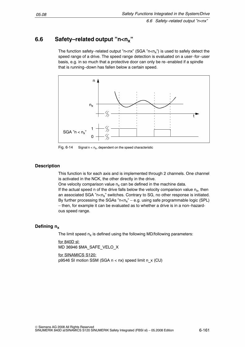
Safety Functions Integrated in the System/Drive
6.6 Safety–related output ”n<nx”
05.08
6-161© Siemens AG 2008 All Rights ReservedSINUMERIK 840D sl/SINAMICS S120 SINUMERIK Safety Integrated (FBSI sl) – 05.2008 Edition
6.6 Safety–related output ”n<nx”
The function safety–related output ”n<nx” (SGA ”n<nx”) is used to safely detect thespeed range of a drive. The speed range detection is evaluated on a user–for–userbasis, e.g. in so much that a protective door can only be re–enabled if a spindlethat is running–down has fallen below a certain speed.
t
SGA ”n < nx”
n
0
1
nx
Fig. 6-14 Signal n < nx, dependent on the speed characteristic
Description
This function is for each axis and is implemented through 2 channels. One channelis activated in the NCK, the other directly in the drive.One velocity comparison value nx can be defined in the machine data.If the actual speed n of the drive falls below the velocity comparison value nx, thenan associated SGA ”n<nx” switches. Contrary to SG, no other response is initiated.By further processing the SGAs ”n<nx” – e.g. using safe programmable logic (SPL)– then, for example it can be evaluated as to whether a drive is in a non–hazard-ous speed range.
Defining nx
The limit speed nx is defined using the following MD/following parameters:
for 840D sl:MD 36946 $MA_SAFE_VELO_X
for SINAMICS S120:p9546 SI motion SSM (SGA n < nx) speed limit n_x (CU)

Safety Functions Integrated in the System/Drive
6.6 Safety–related output ”n<nx”
05.08
6-162© Siemens AG 2008 All Rights Reserved
SINUMERIK 840D sl/SINAMICS S120 SINUMERIK Safety Integrated (FBSI sl) – 05.2008 Edition
Response time and error responses
Typical response time for n < nx:1 interpolation clock cycle + 2 monitoring clock cycles
Maximum response times: 1 position controller clock cycle + 5.5 monitoring clockcycles + 2 interpolation clock cycles + 3 PLC cycles
!Warning
A STOP F (displayed using alarms 27001, 27101 and onwards or F01611) onlyresults in a subsequent STOP B/A response, if at least one of the safety–relatedfunctions SBH, SG, SE or SN is active or selected. If only the function ”n < nx isactive, then a STOP F does not result in a subsequent STOP B/A response.This means that if ”n < nx” is used as a safety function, then at least one of theSBH, SG, SE or SN functions must be active or selected (e.g. by selecting a highSG level).
Note
If the axis/spindle runs at a speed nx, then as a result of actual differences in thetwo monitoring channels, the SGA ”n < nx” can have different states.This must be taken into account in the safe processing of the SGAs.

Safety Functions Integrated in the System/Drive
6.7 Safe software limit switches (SE)
05.08
6-163© Siemens AG 2008 All Rights ReservedSINUMERIK 840D sl/SINAMICS S120 SINUMERIK Safety Integrated (FBSI sl) – 05.2008 Edition
6.7 Safe software limit switches (SE)
Note
The function ”safe software limit switches” (SE) is also known as ”safe limitpositions”.
Description
The ”safe software limit switches” function (SE) can be used to implement protec-tive functions for operating personnel and machinery or working zone/protectionzone delimination for specific axes. For example, this function can replace hard-ware limit switches.
Two ”safe software limit switches” (SE1 and SE2) are available for each axis. If theSE function is active, limit switch position pair SE1 or SE2 can be selected as afunction of SGE ”SE selection”.
Defining the upper and lower limit values
The position limit values for the software limit switch position pairs 1 and 2 are de-fined in the following machine data:
for 840D sl:MD 36934: $MA_SAFE_POS_LIMIT_PLUS[n]MD 36935: $MA_SAFE_POS_LIMIT_MINUS[n]
for SINAMICS S120:p9534[n]: SI motion SLP (SE) upper limit values (Control Unit)p9535[n]: SI motion SLP (SE) lower limit values (Control Unit)
Note
The upper and lower position limit values must be selected so that when the axisis traversing in this direction, the software limit switches – that are used asstandard – are first reached.
Features
The most important features include:
� Software limit switches are safely defined and evaluated as a software function
� Configurable stop response when software limit switches are passed
� The stop response is implemented internally in the software (and is thereforefaster than a hardware limit switch response) when software limit switches arepassed (i.e. actuated)
Safety Functions Integrated in the System/Drive
6.7 Safe software limit switches (SE)
05.08
6-164© Siemens AG 2008 All Rights Reserved
SINUMERIK 840D sl/SINAMICS S120 SINUMERIK Safety Integrated (FBSI sl) – 05.2008 Edition
Prerequisites
The following prerequisites must be fulfilled for the ”safe software limit switches”function:
� The ”safe software limit switches” function must be enabled
� The axis/axes must have been safely referenced (user agreement)
� SGE ”SE selection” must be supplied (configured) in both channels
!Warning
”Safe software limit switches” are only effective if the user agreement has beengiven.
6.7.1 Effects when an SE responds
!Warning
The SE function does not predictively monitor the SW (software) limit switches.This means that the axis stops after passing the limit position. The distancetraveled after the SE is dependent on:
– How the function was parameterized (monitoring clock cycle, stop response,...)
– The actual speed– The design of the axis
Configurable stop responses
When an axis passes (actuates) a ”safe software limit switch”, a stop responseconfigured in the following machine data is generated:
for 840D sl:MD 36962: $MA_SAFE_POS_STOP_MODE
for SINAMICS S120:p9562: SI motion SLP (SE) stop response (Control Unit)
The user can select either STOP C, D or STOP E.
Effect
� The configured stop response is initiated
� The relevant alarm is displayed

Safety Functions Integrated in the System/Drive
6.7 Safe software limit switches (SE)
05.08
6-165© Siemens AG 2008 All Rights ReservedSINUMERIK 840D sl/SINAMICS S120 SINUMERIK Safety Integrated (FBSI sl) – 05.2008 Edition
Acknowledging and moving away
1. Withdraw the user agreement (SE is no longer active) or changeover to another SE.
2. Acknowledge the stop and alarm response.
3. Bring the axis into a range in which the monitoring no longer responds.
Timing when the safe software limit switches are actuated
If the ”safe software limit switches” function is active, the system timing is as fol-lows when the software limit switches are actuated (passed):
na) the end position is passed
tnot to scale
nact
t2
t3
t4
t5
t6
t1
Fig. 6-15 Timing when a software limit switch is actuated
Table 6-20 Explanation of the diagram
Time Explanation
t1 The position control clock cycle, defined by the following MDs:for 840D sl:MD 10050: $MN_SYSCLOCK_CYCLE_TIMEMD 10060: $MN_POSCTRL_SYSCLOCK_TIME_RATIO
t2 Monitoring clock cycle, defined by the following MDs:for 840D sl:MD 10090: $MN_SAFETY_SYSCLOCK_TIME_RATIOfor SINAMICS S120:p9500: SI motion monitoring clock cycle (Control Unit)
t3 Delay until the configured stop response is output(typical 0.5 monitoring clock cycles, maximum 1 monitoring clock cycle + 1 position controllerclock cycle)
t4 Time until the configured stop response becomes effective(typical 1.5 monitoring clock cycles, maximum 2 monitoring clock cycles + 1 position controllerclock cycle)

Safety Functions Integrated in the System/Drive
6.7 Safe software limit switches (SE)
05.08
6-166© Siemens AG 2008 All Rights Reserved
SINUMERIK 840D sl/SINAMICS S120 SINUMERIK Safety Integrated (FBSI sl) – 05.2008 Edition
Table 6-20 Explanation of the diagram
Time Explanation
t5 Time until the stop response that was initiated actually startsSTOP C: typical 2 position controller clock cycles, maximum 2 position controller clock cyclesSTOP D/E: typical 2 interpolation clock cycles, maximum 2 interpolation clock cycles + 2 moni-toring clock cycles
t6 Time required to bring the axis to a standstill.This time and thus the residual distance traveled by the axis is determined by the axis design(motor, mass, friction, ...) and the configured stop response (STOP C is faster than STOP D).
Note:Each axis must be measured during commissioning (start–up) to determine the distance that it travelsbetween the limit switch being violated and it coming to a standstill.

Safety Functions Integrated in the System/Drive
6.8 Safety software cams and safety cam track (SN)
05.08
6-167© Siemens AG 2008 All Rights ReservedSINUMERIK 840D sl/SINAMICS S120 SINUMERIK Safety Integrated (FBSI sl) – 05.2008 Edition
6.8 Safety software cams and safety cam track (SN)
Description
The ”safe software cams” function (SN) can be used to implement safe electroniccams, safe range detection or working zone/protection zone delimination for spe-cific axes, thereby replacing the hardware solution.
!Warning
The enabled cam signals are immediately output when the control system ispowered–up, this output is however only safe after safe referencing (this issignaled using the SGA ”Axis safely referenced”).
The cams are only considered as being safe if they were safely referenced. This isthe reason that the user must interlock this SGA with the cam SGA.
Features
The most important features include:
� Cam positions are safely defined and evaluated as a software function
� Working ranges/zones are defined
Tolerance for SN
Owing to variations in the clock cycle and signal run times (signal propagationtimes), the cam signals of the two monitoring channels do not switch simulta-neously and not precisely at the same position. A tolerance bandwidth can there-fore be specified for all cams using the following machine data/parameters. Withinthis bandwidth, the signal states for the same cam may be different in the twomonitoring channels.
for 840D sl:MD 36940: $MA_SAFE_CAM_TOL
for SINAMICS S120:p9540: SI motion SCA (SN) tolerance (Control Unit)
Note
The lowest possible tolerance bandwidth (less than 5–10 mm) should be selectedfor the ”safe software cams” function. It makes sense to parameterize the camtolerance greater than or equal to the actual value tolerance.

Safety Functions Integrated in the System/Drive
6.8 Safety software cams and safety cam track (SN)
05.08
6-168© Siemens AG 2008 All Rights Reserved
SINUMERIK 840D sl/SINAMICS S120 SINUMERIK Safety Integrated (FBSI sl) – 05.2008 Edition
Effects when SN responds
!Warning
When defining cam positions, please note that the function only monitors theactual position thus making (predictive) sensing of cam signals impossible.
The cams are only considered as being safe if they were safely referenced. This isthe reason that the user must link this SGA in the SPL with the correspondingSGA of the cam functionality.
Response times
� Response times without cam synchronizationtypical1 interpolation clock cycle + 1.5 monitoring clock cyclesmaximum 1 position controller clock cycle + 4 monitoring clock cycles + 2 inter-polation clock cycles + 3 PLC cycles
� Response times with cam synchronizationtypical1 interpolation clock cycle + 2.5 monitoring clock cyclesmaximum 1 position controller clock cycle + 5 monitoring clock cycles + 2 inter-polation clock cycles + 3 PLC cycles
6.8.1 Safe software cams (4 cam pairs)
Note
If more than 4 cam pairs are required, then the ”safe cam track” function must beused (refer to Chapter 6.8.2, ”Safe cam track”).
Description
There are 4 pairs of cams (SN1, SN2, SN3, SN4) available for each axis. Eachcam pair consists of a plus cam (SN1+, SN2+, SN3+, SN4+) and a minus cam(SN1–, SN2–, SN3–, SN4–). Each cam signal can be individually enabled and con-figured via machine data. The cam signals are output via SGAs.

Safety Functions Integrated in the System/Drive
6.8 Safety software cams and safety cam track (SN)
05.08
6-169© Siemens AG 2008 All Rights ReservedSINUMERIK 840D sl/SINAMICS S120 SINUMERIK Safety Integrated (FBSI sl) – 05.2008 Edition
Prerequisites
The following prerequisites must be fulfilled for the ”safe software cams” function:
� The axis/axes must have been safely referenced (user agreement)
� The safe cams must be configured:
The required cams are enabled using machine datafor 840D sl:36901: $MA_SAFE_FUNCTION_ENABLE, bits 8...15 and parameterfor SINAMICS S120:p9501: SI motion, enable safety functions, bits 8...15
SGA assignment is defined using machine datafor 840D sl:36988: $MA_SAFE_CAM_PLUS_OUTPUT[n] and36989: $MA_SAFE_CAM_MINUS_OUTPUT[n]
Defining the cam positions
The cam positions are defined in the following machine data/parameters:
for 840D sl:MD 36936: $MA_SAFE_CAM_POS_PLUS[0...3]MD 36937: $MA_SAFE_CAM_POS_MINUS[0...3]
for SINAMICS S120:p9536[n]: SI motion SCA (SN) plus cam position (Control Unit)p9537[n]: SI motion SCA (SN) minus cam position (Control Unit)
Special case for SN
If the axis is positioned precisely at the parameterized cam position, the cam sig-nals may have different states owing to system–related variations in the actual val-ues between the two monitoring channels.This must be taken into account when safely processing the cam signals, e.g. byfiltering the different signal states by means of a logic circuit (see ”Synchronizingcam signals”).
Synchronizing cam signals
As a result of system–related actual value differences, the cam signals of the mon-itoring channels can have different states. In order to prevent this, the cam syn-chronization can be activated. This rounds off the results of both channels.
The cam SGAs at the input position of the SPL are synchronized if the user hasparameterized this using the function enable.
Cam signal synchronization is enabled using the following machine data/parame-ters:

Safety Functions Integrated in the System/Drive
6.8 Safety software cams and safety cam track (SN)
05.08
6-170© Siemens AG 2008 All Rights Reserved
SINUMERIK 840D sl/SINAMICS S120 SINUMERIK Safety Integrated (FBSI sl) – 05.2008 Edition
for 840D sl:MD 36901: $MA_SAFE_FUNCTION_ENABLE, bit 7
for SINAMICS S120:p9501: SI Motion enable safety functions (Control Unit), bit 7
The cam SGAs including the hysteresis, but without synchronization are displayedin the service screen and servo trace.
Hysteresis of cam SGAs
When cam synchronization is activated, cam signals are output with a hysteresisthat takes into account the approach direction (refer to Figure 6-16, ”Hysteresis ofthe cam SGAs”). This helps to prevent the SGAs from ”flickering” if the axis ispositioned exactly on the cam.The magnitude of the hysteresis is determined by the following data:
for 840D sl:MD 36940: $MA_SAFE_CAM_TOL(tolerance for safe software cams)
for SINAMICS S120:p9540: SI motion SCA (SN) tolerance (Control Unit)
sSGA = 1
Cam position
SGA = 0
Tolerancefor safecams
Fig. 6-16 Hysteresis of cam SGAs
If the cam is incorrectly/inadmissibly parameterized, then this is indicated by Alarm27033.
!Warning
As a result of the cam hysteresis, for increasing actual values, the cams SGA donot switch at the configured cam position (SN) but at the position increased by thecam tolerance (hysteresis) (SN+TOL).
Users must carefully take this into consideration when configuring the campositions and cam tolerance.
Safety Functions Integrated in the System/Drive
6.8 Safety software cams and safety cam track (SN)
05.08
6-171© Siemens AG 2008 All Rights ReservedSINUMERIK 840D sl/SINAMICS S120 SINUMERIK Safety Integrated (FBSI sl) – 05.2008 Edition
Safe software cams for endlessly turning rotary axes
For rotary axes with cams, the modulo range (cam actual value range) can be setusing the following machine data/parameters:
for 840D sl:MD 36902: $MA_SAFE_IS_ROT_AXfor SINAMICS S120:p9502: SI motion axis type (Control Unit)for 840D sl:MD 36905: $MA_SAFE_MODULO_RANGEfor SINAMICS S120:p9505: SI motion SCA (SN) modulo value (Control Unit)
The cam actual value range should be selected as wide as the modulo display ofthe safe actual value.
For rotary axes, the modulo display of safe actual values is selected and para-meterized using the following machine data:
for 840D sl:MD 30300: $MA_IS_ROT_AXMD 30320: $MA_DISPLAY_IS_MODULOMD 30330: $MA_MODULO_RANGE
Limiting the cam positions
When parameterizing the cam positions, the following conditions close to the mo-dulo limits must be maintained.
When cam synchronization is not active:
� – Mod_Pos + Pos_Tol < SN_Pos < Mod_Pos – Pos_Tol
When cam synchronization is active:
� – Mod_Pos + Pos_Tol + Cam_Tol < SN_Pos < Mod_Pos – Pos_Tol – Cam_Tol
Meanings:
Pos_Tol: Actual value toleranceMD 36942: $MA_SAFE_POS_TOL for 840D slp9542: SI motion, actual value comparison tolerance (crosswise) (Control Unit) forSINAMICS S120
Cam_Tol: Cam toleranceMD 36940: $MA_SAFE_CAM_TOL for 840D slp9540: SI motion SCA (SN) tolerance (Control Unit) for SINAMICS S120
Mod_Pos: Lower/upper modulo value:MD 36905: $MA_SAFE_MODULO_RANGE for 840D slp9505: SI motion SCA (SN) modulo value (Control Unit) for SINAMICS S120

Safety Functions Integrated in the System/Drive
6.8 Safety software cams and safety cam track (SN)
05.08
6-172© Siemens AG 2008 All Rights Reserved
SINUMERIK 840D sl/SINAMICS S120 SINUMERIK Safety Integrated (FBSI sl) – 05.2008 Edition
SN_Pos: Cam position: MD 36936: $MA_SAFE_CAM_POS_PLUS[n] for 840D slp9536: SI motion SCA (SN) plus cam position (Control Unit) for SINAMICS S120MD 36937: $MA_SAFE_CAM_POS_MINUS[n] for 840D slp9537: SI motion SCA (SN) minus cam position (Control Unit) for SINAMICS S120
When booting, the parameterization (parameter assignments) are checked in eachmonitoring channel. In the case of parameterization errors (a condition is not ful-filled), Alarm 27033 or F01687 is output after the control has been booted.
6.8.2 Safe cam track (SN)
Description
The ”safe cam track” function is used as an alternative to safe cams (refer toChapter 6.8.1). The user has 4 cam tracks at his disposal. Up to 15 cams can beevaluated on a cam track. A total of 30 cams are available. The information as towhich cam of a cam track is presently active is saved in the SGA ”cam range” (4bits for each cam track) and can together with the SGA ”cam track” be evaluated inthe safe programmable logic (SPL).
Further, the cams are available as SGA safe cam range bits.
Prerequisites
The following prerequisites apply to the ”safe cam track” function:
� The axis/axes must have been safely referenced (user agreement)
� Either the ”safe cams” function or the ”safe cam track” function may be used,i.e. simultaneous enable in the machine data or parametersMD 36903 $MA_SAFE_CAM_ENABLE/p9503 SI motion SCA (SN) enable(Control Unit) andMD 36901 $MA_SAFE_FUNCTION_ENABLE/p9501 SI motion enable safetyfunctions (Control Unit)is not permissible and result in the alarm 27033/C01681 ”Invalid parameteriza-tion”.
� The modulo function is not supported. If the ”safe cam track” function is en-abled and a value > 0 entered in the MD 36905 $MA_SAFE_MODULO_RAN-GE/p9505 SI motion SCA (SN) modular value (Control Unit), then alarm 27033”Axis %1 parameterization of the MD $MA_SAFE_REFP_STATUS_OUTPUT[0]invalid” is output with a reference to $MA_SAFE_MODULO_RANGE.

Safety Functions Integrated in the System/Drive
6.8 Safety software cams and safety cam track (SN)
05.08
6-173© Siemens AG 2008 All Rights ReservedSINUMERIK 840D sl/SINAMICS S120 SINUMERIK Safety Integrated (FBSI sl) – 05.2008 Edition
� The safe cams must be configured:
The required cams are enabled using machine datafor 840D sl:36903: $MA_SAFE_CAM_ENABLE, bits 0...29 and parameterfor SINAMICS S120:p9503: SI motion SCA (SN) enable (Control Unit), bits 0...29
SGA assignment is defined using machine datafor 840D sl:36988: $MA_SAFE_CAM_PLUS_OUTPUT[n] and36989: $MA_SAFE_CAM_MINUS_OUTPUT[n]
Defining the cam positions
The cam positions are defined in the following machine data/parameters:
for 840D sl:MD 36936: $MA_SAFE_CAM_POS_PLUS[0...29]MD 36937: $MA_SAFE_CAM_POS_MINUS[0...29]
for SINAMICS S120:p9536[0...29]: SI motion SCA (SN) plus cam position (Control Unit)p9537[0...29]: SI motion SCA (SN) plus cam position (Control Unit)
Note
The minus position of cam x must be less than the plus position of cam x,otherwise alarm 27033 ”Invalid parameterization” is output. For an incorrectparameterization, also alarm F01686 ”SI Motion: Cam position parameterizationnot permissible” of the drive is also output.
Assignment, cam to cam track
The cams defined in $MA_SAFE_CAM_POS_PLUS[0...29] and$MA_SAFE_CAM_POS_MINUS[0...29] are assigned to a cam track as follows:
for 840D sl:MD 36938: $MA_SAFE_CAM_TRACK_ASSIGN[0...29]
for SINAMICS S120:p9538[0...29]: SI motion cam track assignment (Control Unit)
Range of values:
100...114 = cam range 0...14 at cam track 1200...214 = cam range 0...14 at cam track 2300...314 = cam range 0...14 at cam track 3400...414 = cam range 0...14 at cam track 4The ”hundreds” position defines which cam track is assigned to the cams. The”tens” and ”ones” positions contain the numerical value that is signaled to the SPLas SGA ”cam range”.

Safety Functions Integrated in the System/Drive
6.8 Safety software cams and safety cam track (SN)
05.08
6-174© Siemens AG 2008 All Rights Reserved
SINUMERIK 840D sl/SINAMICS S120 SINUMERIK Safety Integrated (FBSI sl) – 05.2008 Edition
Please note:
� It is not possible to assign a cam a multiple number of times to several tracks.A multiple assignment only functions if an additional cam is parameterized withthe same cam position and assigned to another cam track.
� Cam positions can be freely assigned to a cam range.
� Cams that have not been assigned do not appear on the cam track.
� The cams on a cam track must not overlap.
� The cams on a cam track must have a certain minimum length.
� The cams on a cam track must have a certain minimum distance betweenthem.
Evaluation of the parameterization
For the evaluation, the following checks are made (for the NCK and drive):
� If $MA_SAFE_CAM_ENABLE > 0, then $MA_SAFE_FUNCTION_ENABLE,bits 8–15 must be = 0.
� If $MA_SAFE_CAM_ENABLE > 0, then it is not permissible that the enable bitfor cam synchronization is set (($MA_SAFE_FUNCTION_ENABLE, bit 7 = 0)
� Modulo cams are not permissible ($MA_SAFE_MODULO_RANGE must be 0 if$MA_SAFE_CAM_ENABLE > 0).
� Checking the cam length:
$MA_SAFE_CAM_POS_PLUS[0...29] – $MA_SAFE_CAM_POS_MINUS[0...29] >=$MA_SAFE_CAM_TOL + $MA_SAFE_POS_TOL
� Checking the distance between 2 cams on a cam track:
$MA_SAFE_CAM_POS_MINUS[y] – $MA_SAFE_CAM_POS_PLUS[x] >=$MA_SAFE_CAM_TOL + $MA_SAFE_POS_TOL
� It is not permissible to parameterize two cams on the same track and range:
Example:$MA_SAFE_CAM_TRACK_ASSIGN[2] = 205;$MA_SAFE_CAM_TRACK_ASSIGN[5] = 205;As a consequence, it is not possible to assign more than 15 cams to a camtrack.
� If a cam is enabled in $MA_SAFE_CAM_ENABLE, then it must also be as-signed.
If a violation is determined when making these checks, then alarm 27033 ”Parame-terization invalid”/F01686 ”SI motion: Cam position parameterization not permissi-ble” is output.
The generation of the new cam SGA is shown in Fig. 6-17:

Safety Functions Integrated in the System/Drive
6.8 Safety software cams and safety cam track (SN)
05.08
6-175© Siemens AG 2008 All Rights ReservedSINUMERIK 840D sl/SINAMICS S120 SINUMERIK Safety Integrated (FBSI sl) – 05.2008 Edition
Parameterization example for SGA ”cam track” and ”cam range”
SGA ”cam track”/SGA ”cam range”
Position
SGA ”cam range ” for
cam track 2
SGA ”cam track 2”
15
5
2
3
4
1
SN2– SN2+ SN6+ SN1+SN6– SN3– SN3+ SN8– SN1–SN8+
Fig. 6-17 SGA ”cam track” and ”cam range”
Note
The traversing range for rotary axes must lie within +/–2048 revolutions. Thiscorresponds to the value range of the safety–related actual value.
Parameterization example for Fig. 6-17:
Enabling the cams SN1, SN2, SN3, SN6, SN8:
$MA_SAFE_CAM_ENABLE = 0xA7 (0000 0000 0000 0000 0000 0000 1010 0111);
Parameterizing the cam positions for the cams that have been enabled:
� SN1$MA_SAFE_CAM_POS_PLUS[0] = 480$MA_SAFE_CAM_POS_MINUS[0] = 455
� SN2$MA_SAFE_CAM_POS_PLUS[1] = 120$MA_SAFE_CAM_POS_MINUS[1] = 80
� SN3$MA_SAFE_CAM_POS_PLUS[2] = 320$MA_SAFE_CAM_POS_MINUS[2] = 300
� SN6$MA_SAFE_CAM_POS_PLUS[5] = 200$MA_SAFE_CAM_POS_MINUS[5] = 170
� SN8$MA_SAFE_CAM_POS_PLUS[7] = 380$MA_SAFE_CAM_POS_MINUS[7] = 350
Parameterizing the cam range assignment:(all cams that have been enabled are assigned to cam track 2)

Safety Functions Integrated in the System/Drive
6.8 Safety software cams and safety cam track (SN)
05.08
6-176© Siemens AG 2008 All Rights Reserved
SINUMERIK 840D sl/SINAMICS S120 SINUMERIK Safety Integrated (FBSI sl) – 05.2008 Edition
� $MA_SAFE_CAM_TRACK_ASSIGN[0] = 201(cam SN1 is assigned cam range 1)
� $MA_SAFE_CAM_TRACK_ASSIGN[1] = 203(cam SN2 is assigned cam range 3)
� $MA_SAFE_CAM_TRACK_ASSIGN[2] = 202(cam SN3 is assigned cam range 2)
� $MA_SAFE_CAM_TRACK_ASSIGN[5] = 204(cam SN6 is assigned cam range 4)
� $MA_SAFE_CAM_TRACK_ASSIGN[7] = 205(cam SN8 is assigned cam range 5)
Behavior of the SGA
The SGA ”cam track” is the OR logic operation of all individual cams on a camtrack. If an axis is at a cam on a cam track, then the SGA of this cam track is setto 1. Together with the SGA ”cam range”, information is available as to which camis presently active.
The SGA ”cam range” starts at the lower end of the traversing range with therange of the first cam – assigned in $MA_SAFE_CAM_TRACK_ASSIGN[n] – onthis cam track, i.e. in this case ”3”. At the upper end after the last cam on this camtrack, the range SGA is set to ”15”. The transition of the range to the next value isrealized when moving in the positive direction always at the falling edge of an indi-vidual cam.
The enable machine data as well as all cam limit values and range assignmentsare compared crosswise between the NCK and drive.
The user can use the following to connect to the SPL interface($A_INSI/$A_OUTSI)
– SGA ”cam track”, MD 37900: $MA_SAFE_CAM_TRACK_OUTPUT[0...3]and for the
– SGA ”cam range”, MD 37901–37904: $MA_SAFE_CAM_RANGE_OUT-PUT_1/2/3/4[0...3] and for the
– SGA ”cam range bits”, machine data 37906–37909$MA_SAFE_CAM_RANGE_BIN_OUTPUT_1/2/3/4[0...14].
Specified machine data follow the generally valid rules when assigning the safety–related inputs/outputs.
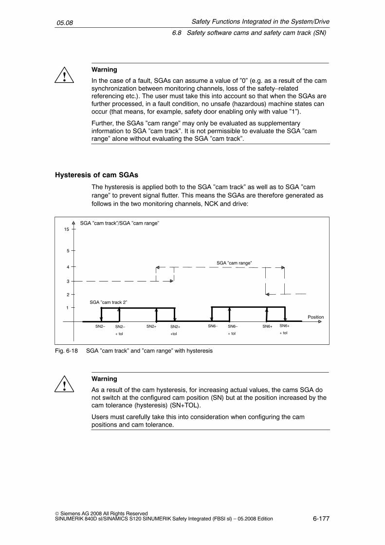
Safety Functions Integrated in the System/Drive
6.8 Safety software cams and safety cam track (SN)
05.08
6-177© Siemens AG 2008 All Rights ReservedSINUMERIK 840D sl/SINAMICS S120 SINUMERIK Safety Integrated (FBSI sl) – 05.2008 Edition
!Warning
In the case of a fault, SGAs can assume a value of ”0” (e.g. as a result of the camsynchronization between monitoring channels, loss of the safety–relatedreferencing etc.). The user must take this into account so that when the SGAs arefurther processed, in a fault condition, no unsafe (hazardous) machine states canoccur (that means, for example, safety door enabling only with value ”1”).
Further, the SGAs ”cam range” may only be evaluated as supplementaryinformation to SGA ”cam track”. It is not permissible to evaluate the SGA ”camrange” alone without evaluating the SGA ”cam track”.
Hysteresis of cam SGAs
The hysteresis is applied both to the SGA ”cam track” as well as to SGA ”camrange” to prevent signal flutter. This means the SGAs are therefore generated asfollows in the two monitoring channels, NCK and drive:
SGA ”cam track”/SGA ”cam range”
Position
SGA ”cam range”
SGA ”cam track 2”
15
5
2
3
4
1
SN2– SN2–
+ tol
SN2+
+tol
SN6+
+ tol
SN2+ SN6– SN6+SN6–
+ tol
Fig. 6-18 SGA ”cam track” and ”cam range” with hysteresis
!Warning
As a result of the cam hysteresis, for increasing actual values, the cams SGA donot switch at the configured cam position (SN) but at the position increased by thecam tolerance (hysteresis) (SN+TOL).
Users must carefully take this into consideration when configuring the campositions and cam tolerance.

Safety Functions Integrated in the System/Drive
6.8 Safety software cams and safety cam track (SN)
05.08
6-178© Siemens AG 2008 All Rights Reserved
SINUMERIK 840D sl/SINAMICS S120 SINUMERIK Safety Integrated (FBSI sl) – 05.2008 Edition
Synchronization
The synchronization of the cam SGA is carried out between the NCK and PLC.Both the SGA ”cam track” as well as the SGA ”cam range” must be synchronized.
The SGA ”cam track” is synchronized by AND’ing the two signals from the NCKand drive monitoring channels. The logic operation is carried out for all 4 cam posi-tions.
The 4–bit SGA ”cam range” (value range 0...15) is synchronized according to thefollowing rule:
If the SGA ”cam range” as well as the SGA ”cam track” is different in both monitor-ing channels and the SGA ”cam track” of its own channel has a value of ”1”, thenthe SGA ”cam range” of the other channel must be used.
Alternative evaluation of the cam signals
In order to simplify the evaluation of cam signals, the cam signals ”cam track” and”cam range”, generated from the axis monitoring channels NCK and drive can bemapped to 15 ”cam range bits” for each cam track (for the cam ranges 0 ... 14).
The ”cam range bits” are generated by logically combining the ”cam track” and”cam range” signals in the NCK and in the PLC. If the axis is positioned at a cam,then the cam range bit of the cam range assigned to this cam is set to 1.
The SGA ”cam track”, ”cam range” and ”cam range bit” are shown in the Fig. 6-19using an example:

Safety Functions Integrated in the System/Drive
6.8 Safety software cams and safety cam track (SN)
05.08
6-179© Siemens AG 2008 All Rights ReservedSINUMERIK 840D sl/SINAMICS S120 SINUMERIK Safety Integrated (FBSI sl) – 05.2008 Edition
SGA ”cam range ” for cam track 2
Position
15
5
2
3
4
1
SGA ”cam track 2”1
SN2– SN2+ SN6+SN6– SN3– SN3+ SN8– SN8+0
SGA ”cam range bit [2]” for
cam track 21
0
SGA ”cam range bit [3]” for
cam track 21
0
SGA ”cam range bit [4]” for
cam track 21
0
SGA ”cam range bit [5]” for
cam track 21
0
Fig. 6-19 SGA ”cam track” and ”cam range”
Explanation
� Cam SN2 is assigned to track 2 by parameterizing cam range 3($MA_SAFE_CAM_TRACK_ASSIGN[1] = 203). If the axis is at cam SN2, SGA”cam range bit [3]” (index 3 stands for cam range 3) is set to 1.
� Cam SN6 is assigned to track 2 by parameterizing cam range 4($MA_SAFE_CAM_TRACK_ASSIGN[5] = 204). If the axis is at cam SN6, SGA”cam range bit [4]” (index 4 stands for cam range 4) is set to 1 etc.
� ...

Safety Functions Integrated in the System/Drive
6.8 Safety software cams and safety cam track (SN)
05.08
6-180© Siemens AG 2008 All Rights Reserved
SINUMERIK 840D sl/SINAMICS S120 SINUMERIK Safety Integrated (FBSI sl) – 05.2008 Edition
Space for your notes

7-181© Siemens AG 2008 All Rights ReservedSINUMERIK 840D sl/SINAMICS S120 SINUMERIK Safety Integrated (FBSI sl) – 05.2008 Edition
Connecting Sensors/Actuators
7.1 Safety–related input/output signals
7.1.1 Overview of the SGEs/SGAs and their structure
Description
The safety–related input and output signals (SGEs and SGAs) are the interface ofthe internal Safety Integrated functionality to the process.
SGE signals (safety–related input signals) control the active monitoring by dese-lecting or selecting the safety functions. This is realized, among other things, de-pending on the status (switching status) of sensors and transmitters.
SGA signals (safety–related output signals) are feedback signals from safety func-tions. They are, among other things, suitable for controlling actuators in a safety–related fashion.
Processing I/O signals for the NC and drive through two channels
A two–channel structure is used to input/output and process safety–related input/output signals (refer to Figure 7-1 ”NCK and drive monitoring channel”). All of therequests and feedback signals for safety–related functions should be entered orretrieved through both monitoring channels (two–channel structure).
7

Connecting Sensors/Actuators
7.1 Safety–related input/output signals
05.08
7-182© Siemens AG 2008 All Rights Reserved
SINUMERIK 840D sl/SINAMICS S120 SINUMERIK Safety Integrated (FBSI sl) – 05.2008 Edition
Process
Motor
Comparator
Data
Comparator
Data
Drive monitoring channel
System
Interface
Interface
NCK–SPL
NCK signal processing
NCKSGE/SGAsignals
PLC–SPL
PLC signal processing
PROFIsafe
ExternalSGE/SGA
InternalSGE/SGA
Bus
NCK monitoring channel
CDC CDC CDCP
RO
FIs
afe
PR
OF
Isaf
e
NC/PLCinterface:
Axis/spindle DB
Fig. 7-1 NCK and drive monitoring channel
For the NCK monitoring channel, signals are input/output via the SPL – possiblyprocessed by the NCK (see Chapter 7.1.5 ”Multiple distribution and multiple inter-locking”) and emulated (mapped) in the NCK–SGE/SGA interface.
The signals from the drive monitoring channel are input/output via the SPL andsent to the drive via the interface axis/spindle DB.
Internal SGE/SGA (interface to the various axial safety functions) are, e.g. select-ing and deselecting safety functions, changing–over limit values, output of statussignals. They are defined for the particular Safety Integrated functions.
Sensors – e.g. switches, pushbuttons, protective door contacts, emergency stopbuttons, light curtains, laser scanners – are connected to the external SGE (inter-face to the process, i.e. to the machine). Actuators – e.g. load contactors, valves,interlocking solenoids – are connected to the external SGA. The connection is es-tablished through the PROFIsafe I/O, also see Chapter 7.2. Generally, a brake isdirectly connected at the Motor Modules via terminals.
The external and internal SGE/SGA are freely interlocked (logically combined) bythe user using the ”safe programmable logic” (SPL), also see Chapter 7.3.
Crosswise data comparison is implemented between the monitoring channels thatoperate independently of one another. If there is inequality, then a STOP F is initi-ated (crosswise data comparison between the drive and NCK).

Connecting Sensors/Actuators
7.1 Safety–related input/output signals
05.08
7-183© Siemens AG 2008 All Rights ReservedSINUMERIK 840D sl/SINAMICS S120 SINUMERIK Safety Integrated (FBSI sl) – 05.2008 Edition
A STOP D/E is triggered for an SPL crosswise data comparison error. SGE/SGAare set into the safe state if an error is detected by the communication crosswisedata comparison.
Note
As a result of the two–channel structure of Safety Integrated, the machinemanufacturer must supply the SGE and SGA in both the NCK monitoring channeland the drive monitoring channel.
The actual signal state of the SGE/SGA is displayed using the ”Service display”menu. Information regarding Safety Integrated data with the associated axisnames and the axis number are displayed in the ”Service SI” window.
SGE/SGA are, for Safety Integrated, connected through PROFIBUS with the PRO-FIsafe profile and I/O modules that are PROFIsafe–capable. Internal SGE/SGAsignals are accessed via the SPL (see Chapter 7.3 ”Safe programmable logic(SPL)”).
PROFIBUSwith
PROFIsafe
Fig. 7-2 External SGE/SGA via PROFIBUS with the PROFIsafe profile
For instance, the following can be requested or signaled in each monitoring chan-nel and for each/spindle with safety technology using SGE/SGA signals:
� Safety functions can be selected and deselected
� Limit values can be selected and changed–over
� States relating to safety operation can be fed back

Connecting Sensors/Actuators
7.1 Safety–related input/output signals
05.08
7-184© Siemens AG 2008 All Rights Reserved
SINUMERIK 840D sl/SINAMICS S120 SINUMERIK Safety Integrated (FBSI sl) – 05.2008 Edition
Features
� SGE and SGA signals are processed through two channels
� Processed in the NCK monitoring channel
� Processed in the drive monitoring channel
� Safety functions are selected/deselected independent of the NC mode
� Differences in the active SGE/SGA in the monitoring channels are detected inthe crosswise data/result comparison
The access to SGE/SGA signals is described in Chapter 7.2 ”Connecting I/O viaPROFIsafe” and Chapter 7.3 ”Safe programmable logic (SPL)”.
!Warning
The state of a deleted SGE/SGA (logical ”0”) that can be achieved both by theuser as well as also using fault responses of the ”SINUMERIK Safety Integrated”system, are defined as so–called ”fail–safe state” of an SGE/SGA. This is thereason that the system is only suitable for applications where this statecorresponds to the fail–safe state of the process controlled by ”SINUMERIKSafety Integrated”.

Connecting Sensors/Actuators
7.1 Safety–related input/output signals
05.08
7-185© Siemens AG 2008 All Rights ReservedSINUMERIK 840D sl/SINAMICS S120 SINUMERIK Safety Integrated (FBSI sl) – 05.2008 Edition
Which SGEs/SGAs are there?
For each axis/spindle, the following SGE and SGA are in each monitoring channel:
SBH/SGSESN
SGE
SGA
SBH/SG deselectionSBH deselectionSG selection, bit 0, 1SE selectionRatio selection, bits 0, 1, 2
SG correction selection, bits 0, 1, 2, 3ext. STOP A deselectionext. STOP C deselectionext. STOP D deselection
SBH/SG activeAxis safely referenced
n < nx
SBH activeStatus, pulses cancelled (drive)STOP A/B active
STOP C active
STOP D active
STOP E active
ext. STOP E deselection
Test stop selection (drive)Close brake (drive)
Safe cam range for cam track 1, bits 0–3Safe cam range for cam track 2, bits 0–3Safe cam range for cam track 3, bits 0–3
Safe cam range for cam track 4, bits 0–3
SG active, bits 0, 1
Safe cam tracks 1, 2, 3, 4
Cam range bits per bit 0–15 for cam tracks 1, 2,3, 4
SN1–, SN2–, SN3–, SN4–SN1+, SN2+, SN3+, SN4+
Fig. 7-3 SGE and SGA in every monitoring channel for each axis/spindle
Note
The SGE/SGA signals are described in Chapter 8.3, ”Description of Interfacesignals”.
NCK–SGE/SGA
The signals are assigned to the NCK–SPL inputs/outputs using machine data.

Connecting Sensors/Actuators
7.1 Safety–related input/output signals
05.08
7-186© Siemens AG 2008 All Rights Reserved
SINUMERIK 840D sl/SINAMICS S120 SINUMERIK Safety Integrated (FBSI sl) – 05.2008 Edition
Note
Only the NCK–SGE are assigned to an NCK–SPL output that are also required forthe particular application. For axes, where for example, the gear ratio does notchange, the NCK–SGE ”ratio selection bit 2 to 0” do not have to be assigned toSPL inputs. A value of 0 should be entered into the associated MD (i.e. theNCK–SGE does not have an SPL assignment and is set to 0). This does not applyto external STOPs that are not used.
PLC SGEs/SGAs
For the drive monitoring channel, the NC/PLC interface (axis/spindle DB) repre-sents the SGE/SGA interface between the PLC and the drive. The PLC user pro-gram must supply this interface.
Note
Only the PLC–SGE should be processed in the PLC user program that are alsorequired for the particular application. SGE that are not used must be set to thevalue 0 – i.e. to a defined state. This does not apply to external STOPs that arenot used.
See Chapter 6.3.8 ”Forced checking procedure of the external STOPs” forinformation about SGE/SGA for the test stop for external stops.
How many SGE/SGA are required as a minimum?
Depending on the particular application, only some of the maximum number ofSGE/SGA available are required.
Table 7-1 SGE/SGA required as a minimum
Function Minimum SGEs required Minimum SGAs required
Safe operatingstop (SBH)
SBH/SG deselectionTest stop selection (drive)External stops
SBH/SG activeStatus, pulses cancelled(drive)STOP A/B, C, D, E active(only if required)
if gearbox stages are being usedGear ratio selection, bit 2 (only if it is necessary toselect the ratio)Gear ratio selection, bit 1 (only if it is necessary toselect the ratio)Gear ratio selection, bit 0 (only if it is necessary toselect the ratio)

Connecting Sensors/Actuators
7.1 Safety–related input/output signals
05.08
7-187© Siemens AG 2008 All Rights ReservedSINUMERIK 840D sl/SINAMICS S120 SINUMERIK Safety Integrated (FBSI sl) – 05.2008 Edition
Table 7-1 SGE/SGA required as a minimum
Function Minimum SGAs requiredMinimum SGEs required
Safely reducedspeed (SG)
SBH/SG deselectionSBH deselectionSG selection, bit 1 (only for SG changeover)SG selection, bit 0 (only for SG changeover)Test stop selection (drive)External stops
SBH/SG activeStatus, pulses cancelled(drive)
STOP A/B, C, D, E active(only where required)active SG stage, bits 0, 1
if gearbox stages are being usedGear ratio selection, bit 2 (only if it is necessary to se-lect the ratio)Gear ratio selection, bit 1 (only if it is necessary to se-lect the ratio)Gear ratio selection, bit 0 (only if it is necessary to se-lect the ratio)
active SG stage, bits 0, 1(only where required)
Safe softwarelimit switches(SE)
SE selection (only for SE changeover)Test stop selection (drive)SBH/SG deselection (at least for test during commissioning [start–up])External stops
SBH/SG activeAxis safely referencedStatus, pulses cancelled(drive)STOP A/B, C, D, E active(only where required)
Safe softwarecams (SN)
Test stop selection (drive)SBH/SG deselection(at least for test during commissioning [start–up])External stops
SBH/SG activeSTOP A/B, C, D, E active(only where required)Axis safely referencedSN1–, SN2–, ..., SN30–(only where required)SN1+, SN2+, ..., SN30+(only where required)Status, pulses cancelled(drive)
Different signal run times in the channels
The signal timing in the two monitoring channels varies (the PLC cycle time takesup most of the available time in the drive monitoring channel). To prevent thecrosswise data comparison function from being immediately activated after a signalchange, a tolerance time is defined using the following machine data.
for 840D sl:MD 36950: $MA_SAFE_MODE_SWITCH_TIME
for SINAMICS S120:p9550: SI motion SGE changeover tolerance time (Control Unit)
This data specifies the time period for which different signal states may be toler-ated after the SGEs have been changed–over before an error message is output.

Connecting Sensors/Actuators
7.1 Safety–related input/output signals
05.08
7-188© Siemens AG 2008 All Rights Reserved
SINUMERIK 840D sl/SINAMICS S120 SINUMERIK Safety Integrated (FBSI sl) – 05.2008 Edition
Note
System–related minimum tolerance time2 x PLC cycle time (maximum cycle) + 1 x IPO cycle time
7.1.2 Forced checking procedure of SPL signals
Basic principles
Safety–related input/output signals including the connecting cables to the I/O(peripherals) and the sensors and actuators connected to them must always besubject to a forced–checking procedure (see Chapter 5.3 ”Forced checking proce-dure”).The scope of the forced checking procedure should be implemented correspondingto the subsequent conditions.
This means that the selection of a suitable forced checking procedure concept de-pends on the specific application and the specific sensor and/or actuator; this deci-sion must be made by the user. In this scope, the user must configure the forcedchecking procedure.
SPL signals
The forced checking procedure of SPL signals is a part of the SPL functionality(see Chapter 7.3 ”Safe programmable logic (SPL))”.Once the external safety circuit has been wired, a two–channel SPL has beencreated and the relevant safety functions configured and checked with an accep-tance test, the long–term reliability of this function, verified using an acceptancetest, can be ensured:
� External inputs/outputsThe external inputs/outputs of the SPL ($A_INSE or $A_OUTSE) must be sub-ject to a forced checking procedure to ensure that faults do not accumulate overa period of time which would mean that both monitoring channels could fail.
� Internal inputs/outputsInternal inputs/outputs ($A_INSI, $A_OUTSI), markers ($A_MARKERSI) etc.($A_TIMERSI) do not have to be subject to a forced checking procedure. It willalways be possible to detect an error at these locations due to the differing two–channel responses of the external inputs/outputs or the NCK/drive monitoringchannels; crosswise data comparison is carried out at both ends of the re-sponse chain to detect any errors.

Connecting Sensors/Actuators
7.1 Safety–related input/output signals
05.08
7-189© Siemens AG 2008 All Rights ReservedSINUMERIK 840D sl/SINAMICS S120 SINUMERIK Safety Integrated (FBSI sl) – 05.2008 Edition
Test signals
”3–terminal concept” (see Chapter 7.1.3 ”Connecting sensors – actuators usingthe 3–terminal concept”):
� If an input signal ($A_INSE)is, for example, evaluated through two channels ,the associated test output signal can be implemented using one channel. It isextremely important that the input signal can be forced/changed and checked inboth channels.
� In the same way, the assigned test input signal for two–channel output signals($A_OUTSE) can be implemented in one channel if it is connected according tothe following rule:The test input signal may only return an ”OK” status (”1” signal level) if bothoutput signals function (i.e. both monitoring channels have output a ”0”).A simultaneous test in both channels allows the correct functioning in bothchannels to be checked using one feedback signal.
Trigger/test
The timer or event controlled triggering of the forced checking procedure is acti-vated in one channel by the PLC.
If errors are detected, the PLC user program should respond by initiating an exter-nal ”STOP D/E” and switching the external SGAs into a safe state.
Notes to avoid errors
1. A ”2–terminal concept” in which a single–channel net (useful) signal is to besubject to a forced checking procedure using a single–channel test signal isnot permitted. In this case, the two–channel SPL structure would be worthlessand crosswise data comparison would have no effect.
The following are permitted:
� A ”full 4–terminal concept for sensors” (two–channel test signal for a two–channel useful [net] signal),
� the ”3–terminal concept for sensors/actuators” recommended above
� a ”2–terminal concept for sensors without test signals”, if the two–channelnet (useful) signal to be tested automatically changes its level dynamicallyas a result of the process – e.g. for the input signals of a protective door,
� a ”2–terminal concept for sensors without test signals”, if the sensor is asafety–related component, e.g. light curtains,
� a ”2–terminal concept for actuators without test signals”, if the actuator is asafety–related component, e.g. safety valves,
� a ”2–terminal concept for actuators without test signals” if the feedback sig-nal can be checked using other useful signals – e.g. for a valve that indi-rectly switches a BERO via the process and this is available for evaluation,
� a ”2–terminal concept for actuators without test signals” if the function of themechanical system can be checked using other useful signals – e.g. for abrake that is checked using a separate brake test.

Connecting Sensors/Actuators
7.1 Safety–related input/output signals
05.08
7-190© Siemens AG 2008 All Rights Reserved
SINUMERIK 840D sl/SINAMICS S120 SINUMERIK Safety Integrated (FBSI sl) – 05.2008 Edition
2. The signals ”external STOPs” are processed internally in a special way:
� In order to increase the level of security that a requested ”external STOP”actually takes effect, the STOPs are internally exchanged between the twochannels. Failure of the stop control function in one channel does not causean error for these signals (in contrast to the mode changeover signals, e.g.”SG/SBH active”) in the crosswise data comparison.While other signals can be subject to a forced checking procedure in paralleland in both channels (and should be – in order to avoid errors being trig-gered by the crosswise data comparison), the ”external STOPs” must besubject to a forced checking procedure one after the other in both chan-nels.
7.1.3 Connecting sensors – actuators using the 3–terminal concept
Basic principle for safety–related signal processing
With the 3–terminal concept, three terminals (signals) are required to connect asensor or actuator. Faults/errors in the sensors and actuators can be detected inconjunction with the SPL–crosswise data comparison and forced checking proce-dure or the forced checking as a result of the process itself. The connecting cablesare generally monitored autonomously by the fail–safe I/O.
The following applies to the safety–related sensor connection:2 safety–related inputs + 1 standard test output.
The following applies to the safety–related actuator connection:2 safety–related outputs + 1 standard test input.
Example of an actuator connection
2 outputs (to control through 2 channels via SGA) and 1 standard test input (for theforced checking procedure) are required to connect an actuator in a safety–relatedfashion. The test input is the feedback signal from the load circuit and is fed fromthe power supply voltage of a standard input module. The user should derive thisas directly as possible from the process quantity.
Actuator control, P/M switching:
The actuator is directly controlled using a plus potential (P–switching) and minuspotential (M–switching). If the actuator is not a qualified component (safety compo-nent or component with fault exclusion), then in the case that the actuator fails, theuser must apply additional cascaded measures in order to bring the process into asafe condition.

Connecting Sensors/Actuators
7.1 Safety–related input/output signals
05.08
7-191© Siemens AG 2008 All Rights ReservedSINUMERIK 840D sl/SINAMICS S120 SINUMERIK Safety Integrated (FBSI sl) – 05.2008 Edition
Example:
The process quantity, e.g. hydraulic pressure, is switched using a standard valvethat is controlled in a safety–related fashion. A pressure sensor signals the statusof the process quantity. If the valve can no longer switch due to a fault condition,then using a safely controlled standard contactor, the motor that is generating thepressure, is shutdown. The advantage of this particular version is that componentscan be used that are already available as standard. As to whether this solution canbe used, must be confirmed as a result of the risk assessment (see Fig. 7-4).
ET 200S PROFIsafe
PROFIBUSwithPROFIsafe
Feedback
Feedback
Pressuresensor
Shutdown,channel 1
Shutdown,channel 2
24 V loadcircuit, valve
400 V loadcircuit, motor
IM 151–1High Feature
F–DO DI PM–E F
When OK, only the valve isswitched. The pumpremains powered–up.
In the case of a fault, thefeedback signal from thepressure sensor is notreceived, the pump motor isadditionally switched.
Fig. 7-4 Cascaded shutdown using fail–safe outputs
In other cases a second actuator must be connected in series in the load circuit(see Fig. 7-5).
In conjunction with the safety–related control of a brake, no feedback signal isavailable. The brake test will identify as to whether the actuator is correctly func-tioning from a mechanical perspective.
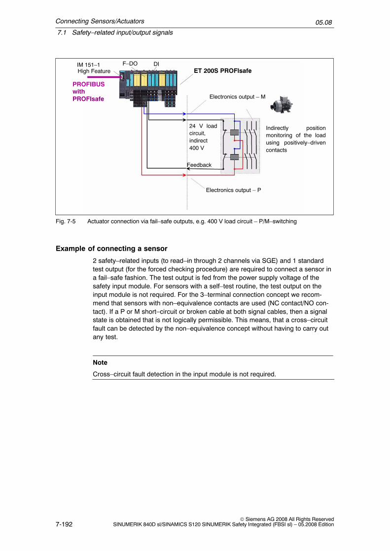
Connecting Sensors/Actuators
7.1 Safety–related input/output signals
05.08
7-192© Siemens AG 2008 All Rights Reserved
SINUMERIK 840D sl/SINAMICS S120 SINUMERIK Safety Integrated (FBSI sl) – 05.2008 Edition
PROFIBUSwithPROFIsafe
ET 200S PROFIsafeIM 151–1High Feature
F–DO DI
Indirectly positionmonitoring of the loadusing positively–drivencontacts
Electronics output – M
Electronics output – P
24 V loadcircuit,indirect400 V
Feedback
Fig. 7-5 Actuator connection via fail–safe outputs, e.g. 400 V load circuit – P/M–switching
Example of connecting a sensor
2 safety–related inputs (to read–in through 2 channels via SGE) and 1 standardtest output (for the forced checking procedure) are required to connect a sensor ina fail–safe fashion. The test output is fed from the power supply voltage of thesafety input module. For sensors with a self–test routine, the test output on theinput module is not required. For the 3–terminal connection concept we recom-mend that sensors with non–equivalence contacts are used (NC contact/NO con-tact). If a P or M short–circuit or broken cable at both signal cables, then a signalstate is obtained that is not logically permissible. This means, that a cross–circuitfault can be detected by the non–equivalence concept without having to carry outany test.
Note
Cross–circuit fault detection in the input module is not required.

Connecting Sensors/Actuators
7.1 Safety–related input/output signals
05.08
7-193© Siemens AG 2008 All Rights ReservedSINUMERIK 840D sl/SINAMICS S120 SINUMERIK Safety Integrated (FBSI sl) – 05.2008 Edition
PROFIBUSwithPROFIsafe
ET 200S PROFIsafeIM 151–1High Feature
F–DI
VS
Test output
To activate andde–activate
e.g.EmergencyStop or useragreement
Non–equivalencecontacts (NCcontact/NOcontact) with the3–terminalconcept
Please note! In this case, it is notpossible to connect the buttons inseries!
Fig. 7-6 Sensor connection using fail–safe inputs according to the 3–terminal concept
7.1.4 Sensor connection using the 4–terminal concept
For the 4–terminal concept, four terminals are required at the fail–safe input mod-ule to connect a sensor that utilizes a contact (e.g. Emergency Stop pushbutton).Faults/errors in the sensors and actuators can be detected in conjunction with theSPL–crosswise data comparison and forced checking procedure or the forcedchecking as a result of the process itself. The connecting cables are generallymonitored autonomously by the fail–safe input module.
The following applies to the safety–related sensor connection:2 safety inputs + 2 standard test outputs
Example
2 inputs (to read–in the 2–channel sensor signals via SGE) and 2 standard testoutputs (for the forced checking procedure) are required for the fail–safe connec-tion of a sensor. The test outputs are supplied from the two power supply voltages(VS1, VS2) of the safety input module. For the connection concept with 4 termi-nals, both equivalence (NC contact/NC contact, NO contact/NO contact) as well asnon–equivalence (NC contact/NO contact) contact versions are possible.

Connecting Sensors/Actuators
7.1 Safety–related input/output signals
05.08
7-194© Siemens AG 2008 All Rights Reserved
SINUMERIK 840D sl/SINAMICS S120 SINUMERIK Safety Integrated (FBSI sl) – 05.2008 Edition
Note
Cross–circuit fault detection in the input module is not required. Measures againstcross–circuit faults are required only for equivalence contacts (NC contact/NCcontact, NO contact/NO contact) if the cable has been routed so that it is veryexposed, e.g. for cables connecting handheld terminals. This can be mechanicallyimplemented in the cable, e.g. using the appropriate shielding.
ET 200S PROFIsafeIM 151–1High Feature
Test outputs
F–DI
PROFIBUSwithPROFIsafe
VS 1
VS 1
VS 2
VS 2
Two circuitClosed–circuitprinciple
(de–activation)
e.g.EmergencyStop
e.g. useragreement
Double openconductor loops(activating)
Equivalencecontacts (NC contact/NC contact)with the4–terminalconcept
Equivalencecontacts (NO contact/NO contact) withthe 4–terminalconcept
Fig. 7-7 Sensor connection using the 4–terminal concept

Connecting Sensors/Actuators
7.1 Safety–related input/output signals
05.08
7-195© Siemens AG 2008 All Rights ReservedSINUMERIK 840D sl/SINAMICS S120 SINUMERIK Safety Integrated (FBSI sl) – 05.2008 Edition
7.1.5 Multiple distribution and multiple interlocking
Interlocking functions between the SGE/SGA are implemented in the NCK channelin the NCK–SPL. However, in order to relieve the NCK–SPL, it is also possible topre–process signals between the NCK–SPL and NCK monitoring channel usingthe ”multiple distribution” and ”multiple interlocking” functions.
Note
The multiple distribution/interlocking that can be parameterized in the NCKmachine data must be programmed by the user on the PLC side.
Processing the NCK–SGE for 840D sl (multiple distribution)
Axis–specific/spindle–specific machine data is used to define which internal SPLoutput is to be used for which function and which axis/spindle. Under the conditionthat certain axes/spindles belong to the same safety group, it is possible to imple-ment multiple distribution (1 NCK–SPL output is assigned, for example, to 3 axeswith the same function). In addition, when an internal NCK–SPL output is selectedvia MD, it is also possible to define whether the inverted signal is also to be pro-cessed.
Inversion
for axis 1
for axis 2
for axis 3
...
... ...
... ...
...
...
...
...
...
...
...
...
...
...
Inversion
...
...
...
...
SGE ...
SGE ...
SGE ...
Multipledistribution
Monitoringcomparators
NCK
SGE/SGA
interface
NCK–SPL
Yes/no
Yes/no
Yes/no
Output 1
Output 2
Output x
Output n
OUTSI
Fig. 7-8 Multiple distribution for NCK––SGE

Connecting Sensors/Actuators
7.1 Safety–related input/output signals
05.08
7-196© Siemens AG 2008 All Rights Reserved
SINUMERIK 840D sl/SINAMICS S120 SINUMERIK Safety Integrated (FBSI sl) – 05.2008 Edition
Example
It must be possible to change over between the ”safe software limit switches” 1 or2 for axes 1, 2 and 3 as a group using an internal NCK–SPL output (OUTSI x).The machine data must be parameterized as follows:
Axis 1: MD 36973: $MA_SAFE_POS_SELECT_INPUT = OUTSI xAxis 2: MD 36973: $MA_SAFE_POS_SELECT_INPUT = OUTSI xAxis 3: MD 36973: $MA_SAFE_POS_SELECT_INPUT = OUTSI x
Processing the NCK–SGA for 840D sl (multiple assignment)
Axis–specific/spindle–specific machine data is used to define which SGA fromwhich axis/spindle must be assigned to which NCK–SPL input. It is possible to im-plement a multiple assignment (SGA from several axes are assigned to 1 input)provided that certain axes/spindles belong to the same safety group. The SGA arethen ANDed and the result output at the NCK–SPL input. In addition, when anNCK output is selected via an MD, it is also possible to define whether the signal isto be output in an inverted form before it is ANDed.
for axis 1
for axis 2
for axis 3
Inversion
......
...
...
...
......
...
...
...
...
SGA
SGA
SGA
...
...
...
...
...
...
...
...
...
&
...
Multipleassignment
Monitoringcomparators
NCKSGE/SGAinterface
NCK–SPL
Yes/no
Yes/no
INSI
Input 1
Input 2
Input x
Input n
Yes/no
Fig. 7-9 Multiple assignment for NCK–SGA

Connecting Sensors/Actuators
7.1 Safety–related input/output signals
05.08
7-197© Siemens AG 2008 All Rights ReservedSINUMERIK 840D sl/SINAMICS S120 SINUMERIK Safety Integrated (FBSI sl) – 05.2008 Edition
Example
Axes 1, 2 and 3 belong to one safety area. For these axes, the message ”axissafely referenced” should be output at one NCK–SPL input (INSI) (this means thatthe message is output at the input if the message (signal) is present for all 3 axes).The machine data must be parameterized as follows:
Axis 1: MD 36987: $MA_SAFE_REFP_STATUS_OUTPUT = INSI xAxis 2: MD 36987: $MA_SAFE_REFP_STATUS_OUTPUT = INSI xAxis 3: MD 36987: $MA_SAFE_REFP_STATUS_OUTPUT = INSI x

Connecting Sensors/Actuators
7.2 Connecting I/O via PROFIsafe
05.08
7-198© Siemens AG 2008 All Rights Reserved
SINUMERIK 840D sl/SINAMICS S120 SINUMERIK Safety Integrated (FBSI sl) – 05.2008 Edition
7.2 Connecting I/O via PROFIsafe
7.2.1 Description of Functions
The fail–safe DP master (F master) integrated in the SINUMERIK 840D sl allows,in conjunction with fail–safe DP modules (F modules), fail–safe communicationsalong PROFIBUS DP specified in accordance with the PROFIsafe profile (PROFI-safe communication).
This means that the safety–related input/output signals of the process (machine)are coupled to the Safety Integrated function ”safe programmable logic” (SPL) inthe same way for both the PLC and NCK–SPL via PROFIBUS–DP .Interface X126 is used for this purpose.
Machine control panel
PROFIBUS–DPEthernet DP slave ET 200S
DP slave ET 200S
SINUMERIK 840D sl
HMI
Fig. 7-10 SI I/Os using fail–safe modules connected to PROFIBUS–DP
PROFIBUS DP
PROFIBUS DP is an international, open fieldbus standard specified in the Euro-pean fieldbus Standard EN 50170 Part 2. It is optimized for fast data transfer at thefield level (time critical).
In the case of the components that communicate via PROFIBUS DP, a distinctionis made between master and slave components.
1. Master (active bus device)Components operating on the bus as master determine the data exchange onthe bus and are therefore also designated as active bus devices.
There are two classes of master:
� DP master, Class 1 (DPMC1):Central master devices that exchange information with the slaves in fixedmessage (telegram) cycles.Examples: S7–300 CPU: CPU 317–2 DP etc.

Connecting Sensors/Actuators
7.2 Connecting I/O via PROFIsafe
05.08
7-199© Siemens AG 2008 All Rights ReservedSINUMERIK 840D sl/SINAMICS S120 SINUMERIK Safety Integrated (FBSI sl) – 05.2008 Edition
� DP master, class 2 (DPMC2):Devices for configuration, commissioning, operator control and monitoringduring bus operation.Examples: Programming units, operator control and visualization devices
2. Slaves (passive devices)These devices may only receive, acknowledge and transfer messages to amaster when so requested.Examples: Drives, I/O modules etc.
PROFIsafe
For PROFIsafe, it involves a PROFIBUS profile for fail–safe data transfer betweenfail–safe components (F master and F slave) along PROFIBUS DP.
The PROFIsafe profile is characterized by the fact that the safety–related functionsare implemented in the safe terminal nodes, i.e. the F/CPUs, the distributed slavesand the actuators/sensors/field devices using the standard PROFIBUS functions.
The useful (net) data of the safety function plus the safety measures are sent in astandard data telegram. This does not require any additional hardware compo-nents, since the protocol chips, drivers, repeaters, cables can still be used as theyare. This means that both standard components and F components can be usedon a PROFIBUS system.
SINUMERIK Safety Integrated supports PROFIsafe V1.

Connecting Sensors/Actuators
7.2 Connecting I/O via PROFIsafe
05.08
7-200© Siemens AG 2008 All Rights Reserved
SINUMERIK 840D sl/SINAMICS S120 SINUMERIK Safety Integrated (FBSI sl) – 05.2008 Edition
7.2.2 System structure
PROFIBUS–DP
DP slave ET 200S
Standard DP module
F–module
PLC–SPL
PLC
SINUMERIK 840D sl
Use
r le
vel
Ope
ratin
g sy
stem
leve
l
NCK
DP slave ET 200S
PROFIsafe comm.
Safety Integrated comm.
User communication
DP
clo
ck c
ycle
OB
1 cl
ock
cycl
e
IPO
cyc
leP
RO
FIs
afe
cloc
k cy
cle
SI data SI data
DP data
NCK–SPL
–
PR
OF
Isaf
e cl
ock
cycl
e(O
B40
)
PROFIBUS–DP comm.
SPL–SGE/SGADB18: INSEP/OUTSEP
SPL–SGE/SGA$A_INSE/OUTSE
PROFIsafe
layer
PROFIsafe
layer
DP layer
Safety
Integr. Layer
Safety
Integr. Layer
Fig. 7-11 System structure: SI I/O using F modules connected to PROFIBUS–DP
Just like Safety Integrated, the PROFIsafe system structure also has a 2–channeldiverse system design based on the PLC and NCK–PROFIsafe layer.

Connecting Sensors/Actuators
7.2 Connecting I/O via PROFIsafe
05.08
7-201© Siemens AG 2008 All Rights ReservedSINUMERIK 840D sl/SINAMICS S120 SINUMERIK Safety Integrated (FBSI sl) – 05.2008 Edition
PROFIsafe communication
The principle of PROFIsafe communications between SINUMERIK 840D and the Fmodules on the PROFIBUS–DP is explained in detail below. This is based on thetransfer of the SPL output data $A_OUTSE/$A_OUTSEP to the F–DO modules:
The PROFIsafe layer creates a PROFIsafe telegram (F telegram) in each PROFI-safe cycle with the ANDed SPL output data as F useful (net) data
F useful (net) data = (OUTSEP AND $A_OUTSE)
and the backup data (CRC and the consecutive number) and transfers it to thePROFIBUS layer via the DP data interface.
The PROFIBUS layer transfers a DP telegram with the PROFIsafe telegramcreated by the F layer in each PROFIBUS cycle as DP useful data to the DPslaves. This is independent of the PROFIsafe cycle.
!Warning
It is not guaranteed that simultaneous changes to individual bits in the SPL (NCKand PLC OUTSE), which are interpreted as a contiguous associated bit pattern,are transferred together. It is possible that the receiver briefly receives aninconsistent bit pattern.
Configuring/parameterizing
The configuration and parameterization needed to connect the F modules to theexternal NCK/PLC–SPL interfaces entails the following steps:
1. Generating the configuration using SIMATIC STEP7.
2. Performing a standard SINUMERIK 840D sl commissioning (minimum require-ment).
3. Loading the configuration and the PLC basic and user program modules intothe SINUMERIK 840D sl PLC.
4. Parameterizing the PROFIsafe–relevant SINUMERIK 840D sl machine data.See Chapter 7.2.4 ”Parameterizing the F master (NCK)”.

Connecting Sensors/Actuators
7.2 Connecting I/O via PROFIsafe
05.08
7-202© Siemens AG 2008 All Rights Reserved
SINUMERIK 840D sl/SINAMICS S120 SINUMERIK Safety Integrated (FBSI sl) – 05.2008 Edition
7.2.3 Configuring and parameterizing the PROFIsafe I/O
The information on configuring and parameterizing the PROFIsafe I/O provided inthis chapter essentially refers to the specific requirements of SIMATIC. Completeinformation on configuring and parameterizing PROFIsafe components fromSiemens is provided in the SIMATIC Manuals:
References:
Distributed I/O System ET 200S, Manual
Distributed I/O System ET 200S, Fail–Safe Modules, Manual
Distributed I/O System ET 200pro, Fail–Safe Modules
Distributed I/O Station ET 200eco, Fail–Safe I/O Module
ASIsafe DP/AS–i F–Link
Configuring
The F I/O are configured while configuring the standard PROFIBUS configurationusing STEP 7.
After the ”S7 Distributed Safety” option package or the S7 F configuration packagehas been installed (refer to the Chapter 3.1 ”System prerequisites) the F modulesare available in the hardware catalog of STEP 7: HW Config (if the hardware cata-log is not displayed, open it using the menu command View > Catalog).
Parameter assignment
Both the standard and F parameterization of the F modules is carried out using therelevant properties dialog box of the module. Select the appropriate DP slave (e.g.IM 151–1) in the station window and then open the properties dialog box of therelevant F module in the detailed view.
Note
The parameter assignments specified in this chapter only refer to the ET 200Smodules. Other PROFIsafe devices have a different parameter assignment.
Connecting Sensors/Actuators
7.2 Connecting I/O via PROFIsafe
05.08
7-203© Siemens AG 2008 All Rights ReservedSINUMERIK 840D sl/SINAMICS S120 SINUMERIK Safety Integrated (FBSI sl) – 05.2008 Edition
Parameters: Input/output address
The parameterization of the input/output addresses that an F module occupies inthe input/output address range of the DP master is realized in the properties dialogbox, under:
Dialog: Properties
Tab: AddressesInput: StartOutput: Start
Note
The following conditions apply to the input/output addresses of an F module:
� Input address for PLC317 > 127
� Input address for PLC319 > 512
� Output address = input address
F parameterization
F parameterization is realized in the properties dialog box under:
Dialog: Properties
Tab: Parameter
Parameters > F parameters
The F parameters of the electronic modules are automatically set to the F monitor-ing time of the HW Config and cannot be changed.
The displayed values of the F parameters
� F_source_address
� F_target_address
must be entered into the machine data to parameterize the NCK in a subsequentparameterizing step.

Connecting Sensors/Actuators
7.2 Connecting I/O via PROFIsafe
05.08
7-204© Siemens AG 2008 All Rights Reserved
SINUMERIK 840D sl/SINAMICS S120 SINUMERIK Safety Integrated (FBSI sl) – 05.2008 Edition
!Warning
The PROFIsafe addresses are for unique identification of source and target ofsafety–related communications.
The following applies to pure PROFIBUS–DP subnetworks:The PROFIsafe target address must be unique network–wide* and station–wide**(system–wide). A maximum of 1022 different PROFIsafe target addresses can beassigned.
* A network consists of one or more subnets. ”Network–wide” means acrosssubnet boundaries.** ”Station–wide” means for a station with HW configuration (e.g. a SINUMERIK840D).
F parameters: F_source_address
The F–source–address is the decimal PROFIsafe address of the F master allo-cated automatically by HW Config. The F_source_address is formed from the”basis for PROFIsafe addresses” plus the PROFIBUS address of the PROFI-BUS–DP interface.
Note
To clearly define the PROFIsafe communication, the PROFIsafe address of theF master – assigned by HW Config – must be saved in the F master. To do this,the PROFIsafe address of the F master must be converted from decimal intohexadecimal and entered into the machine data of SINUMERIK 840D sl. Refer toChapter 7.2.4 ”Parameterizing the F master (NCK)”.
F parameters: F_target_address
The F_target_address is the decimal PROFIsafe address of the F module auto-matically allocated by HW Config (the user can change this).
Note
In order to parameterize the PROFIsafe communication relationships, theF master is informed, via the PROFIsafe address of the F module that thisF module is assigned to it. To do this, the PROFIsafe address must be convertedfrom decimal into hexadecimal and entered into the machine data of SINUMERIK840D sl. Refer to Chapter 7.2.4 ”Parameterizing the F master (NCK)”.
The DIL switch setting shown corresponds to the PROFIsafe address to be set atthe DIL switch of the F module.

Connecting Sensors/Actuators
7.2 Connecting I/O via PROFIsafe
05.08
7-205© Siemens AG 2008 All Rights ReservedSINUMERIK 840D sl/SINAMICS S120 SINUMERIK Safety Integrated (FBSI sl) -- 05.2008 Edition
F parameters: F--monitoring time
The F monitoring time defines the maximum time until a new valid F telegram musthave been received from the F master.
Note
If the F monitoring time is configured to be shorter than the PROFIsafe monitoringclock cycle set using the appropriate machine data, when the control runs--up analarm is displayed:
Alarm 27242 ”PROFIsafe: F module %1, %2 incorrect”
Parameters: DO/DI channel x
The channels of an F module are parameterized in the properties dialog box under:
Dialog: Properties
Tab: Parameter
Parameters > Module parameter > DO or DI channel x
F--DI module
The channels of the F--DI module are mapped differently to the NCK/PLC--SPLinputs $A_INSE/INSEP depending on the selected parameterization.
S 2v2 parameterizationFor 2v2 parameterization, the process signals of both channels in the F--DImodule are combined to form one F useful (net) data signal and thus supply anSPL input data.
SINUMERIK 840D sl
ET 200S F--DI module
channel 3
channel 1
channel 2
channel 4
channel 5
channel 6
channel 7
channel 0
Project design: Channel x,y = 2v2
AND
AND
AND
AND
$A_INSE/INSEP[n]
$A_INSE/INSEP[n+1]
$A_INSE/INSEP[n+2]
$A_INSE/INSEP[n+3]
Fig. 7-12 2v2 mapping of the F--DI channels to SPL input data for ET 200S
S 1v1 parameterizationFor 1v1 parameterization, the process signals of both channels are transferredfrom the F--DI module and can thus supply 2 different SPL input data.

Connecting Sensors/Actuators
7.2 Connecting I/O via PROFIsafe
05.08
7-206© Siemens AG 2008 All Rights Reserved
SINUMERIK 840D sl/SINAMICS S120 SINUMERIK Safety Integrated (FBSI sl) -- 05.2008 Edition
ET 200S F--DI module SINUMERIK 840D sl
Configuration, channel x,y = 2v2Configuration, channel x,y = 1v1
AND
AND
channel 0
channel 1
channel 2
channel 3
channel 4
channel 5
channel 6
channel 7
$A_INSE/INSEP[n]
$A_INSE/INSEP[n+1]
$A_INSE/INSEP[n+2]
$A_INSE/INSEP[n+3]
$A_INSE/INSEP[n+4]
$A_INSE/INSEP[n+5]
Fig. 7-13 2v2/1v1 mapping of the F--DI channels to SPL input data
Note
If mixed 2v2 and 1v1 parameterization is used in an F--DI module, this can reducethe number of SPL input data $A_INSE/INSEP that can be used. This is thereason that we recommend that 1v1 is first parameterized followed by 2v2.
If more pieces of F net data of an F--DI module are used then the number relevantbits that can be transferred by parameterizing the channels of the F--DI module,then the control does not recognize this.
Example:For a 2v2 parameterization of all of the channels of the F--DI module:
-- ET 200S F, F--DI module: 4/8 F--DI 24 V DC
The 8 transferred F net data bits contain 4 relevant (bit 0 -- bit 3) and 4non--relevant bits (bit 4 -- bit 7).
F--DO module
The NCK/PLC--SPL outputs $A_OUTSE/OUTSEP are logically combined in the Fdriver to produce an F net (useful) data signal(implicit 2v2 parameterization) andmapped to the channels of the relevant F--DO module.
ET 200S F--DO module
channel 0
channel 1
channel 2
channel 3
SINUMERIK 840D sl
AND
AND
AND
AND
($A_OUTSE[n]
($A_OUTSE[n+1]
($A_OUTSE[n+2]
($A_OUTSE[n+3]
OUTSEP[n])
OUTSEP[n+1])
OUTSEP[n+2])
OUTSEP[n+3])
Fig. 7-14 Mapping the SPL output data to F--DO channels

Connecting Sensors/Actuators
7.2 Connecting I/O via PROFIsafe
05.08
7-207© Siemens AG 2008 All Rights ReservedSINUMERIK 840D sl/SINAMICS S120 SINUMERIK Safety Integrated (FBSI sl) – 05.2008 Edition
PROFIsafe clock cycle and DP cycle time
When parameterizing the PROFIsafe clock cycle, in order to ensure a correctPROFIsafe communication, the DP cycle time, determined by HW Config must beobserved (refer to Chapter 7.2.5 ”Parameterizing the PROFIsafe communication(NCK)”).
After the station has been fully configured, the DP cycle time can be determined byactivating the equidistant (isochronous) bus cycle:
Open the properties dialog box of PROFIBUS in HW Config: DP master of the con-figured station:
Dialog: Properties – DP master systemTab: General
Subnetwork, button: Properties
Dialog: Properties – PROFIBUSTab: Network settings
Button: Options
Dialog: OptionsTab: Equidistance
Checkbox: Activate equidistance bus cycle/Re–calculate equidistant type
(Note: Activate the equidistant bus cycle using the checkbox: ”Activate equidistantbus cycle/recalculate equidistant time”. This can be used to determine the DPcycle time. The equidistant bus cycle should then be deactivated again.
Display field: Equidistant bus cycle
(Note: The value calculated by HW Config and displayed in the display field: ”Equi-distant bus cycle” has the same significance as the DP cycle time)
Abort
Abort
Abort
Note
The DP cycle time calculated by the HW Config is required as guideline toparameterize the PROFIsafe clock cycle (refer to Chapter 7.2.5 ”Parameterizingthe PROFIsafe communication (NCK)”).
The information and instructions in the online documentation should be carefullyobserved before changing the DP cycle time. ”Help” of the relevant dialog box).

Connecting Sensors/Actuators
7.2 Connecting I/O via PROFIsafe
05.08
7-208© Siemens AG 2008 All Rights Reserved
SINUMERIK 840D sl/SINAMICS S120 SINUMERIK Safety Integrated (FBSI sl) – 05.2008 Edition
7.2.4 Parameterizing the F master (NCK)
The F master is parameterized in the machine data of the NCK and comprises thefollowing subareas:
� PROFIsafe communication
– PROFIsafe address of the F master
– PROFIsafe clock cycle
See Chapter 7.2.5 ”Configuring and parameterizing the PROFIsafe I/O”
� SPL–SGE/SGA interface
– PROFIsafe address of the F module
– F net data filter
– SGE/SGA assignment
SPL–SGE interface See Chapter 7.2.6 ”Parameterizing the SPL–SGE interface(NCK)”.
SPL–SGA interface: See Chapter 7.2.7 ”Parameterizing the SPL–SGA inter-face (NCK)”.
7.2.5 Parameterizing the PROFIsafe communication (NCK)
F master address
In order to define a unique and clear communication relationship between F slaveand F master, in addition to the target address (PROFIsafe address of the Fslave), the source address (PROFIsafe address of the F master) must be defined.
The PROFIsafe address of the F master is entered into the following machinedata:
� MD10385: $MN_PROFISAFE_MASTER_ADDRESS(PROFIsafe address of the F master)
Input format: 0s 00 aaaa
– s: Bus segmentRange of values: 5 = DP connection on the PLC side
– aaaa: Hexadecimal PROFIsafe addressRange of values: 1...FA7DH
Note
The PROFIsafe address of the F master is provided under:
� HW Config > Properties dialog box of the F module > F parameter:F_source_address

Connecting Sensors/Actuators
7.2 Connecting I/O via PROFIsafe
05.08
7-209© Siemens AG 2008 All Rights ReservedSINUMERIK 840D sl/SINAMICS S120 SINUMERIK Safety Integrated (FBSI sl) – 05.2008 Edition
If the value entered does not match the value displayed in the F modules, an alarmis issued when the control boots:
� Alarm: 27220 ”PROFIsafe: Number of NCK F modules (%1) < > Number of S7F modules (%2)”
In this case, alarm parameter %2 contains the value 0.
PROFIsafe clock cycle
The PROFIsafe clock cycle defines the time grid in which new F telegrams aregenerated by the F master for transfer to the F modules. The PROFIsafe clockcycle is derived as standard from the interpolation cycle in the ratio 1:1.
As part of the PROFIsafe communications, a cyclic interrupt of the PLC user pro-gram (OB1) is made. This is realized in the PROFIsafe clock cycle via OB40.
In order to reduce the possible resulting computational load, machine data:
� MD 10098: $MN_PROFISAFE_IPO_TIME_RATIO(factor, PROFIsafe communications clock cycle)
can be used to modify the ratio between the PROFIsafe and interpolation clockcycle.
In order to achieve a sufficiently fast response time regarding PROFIsafe–commu-nications, the PROFIsafe clock cycle may not be parameterized greater than25 ms. The selected PROFIsafe clock cycle is displayed in the machine data:
� MD 10099: $MN_INFO_PROFISAFE_CYCLE_TIME(PROFIsafe, communications clock cycle)
For a PROFIsafe clock cycle of greater than 25 ms, when the control boots thenext time, an alarm is displayed:
� Alarm: 27200 ”PROFIsafe cycle time %1 [ms] is too long”
PROFIsafe clock cycle and DP cycle time
The PROFIsafe clock cycle should be parameterized longer than the DP cycle timedisplayed by STEP 7: HW Config. Otherwise, the load (in time) on the PLC userprogram is increased as a result of unnecessary OB40 interrupts.
Note
The PROFIsafe clock cycle should be parameterized so that the following applies:12 ms < PROFIsafe clock cycle < 25 ms

Connecting Sensors/Actuators
7.2 Connecting I/O via PROFIsafe
05.08
7-210© Siemens AG 2008 All Rights Reserved
SINUMERIK 840D sl/SINAMICS S120 SINUMERIK Safety Integrated (FBSI sl) – 05.2008 Edition
PROFIsafe clock cycle overruns
Even if the parameterized software operates error–free in normal operation, runtime fluctuations in the PLC operating system (e.g. processing diagnostic alarms)can mean that the processing of the OB40 interrupt was not able to be completedbefore the start of the next PROFIsafe clock cycle.
In this particular case, the NCK attempts, up to a limit of 50 ms after the last cor-rectly processed PROFIsafe clock cycle, to initiate an OB40 interrupt. The re-peated attempts to initiate the OB40 interrupt are no longer executed in the PRO-FIsafe clock cycle but in the IPO clock cycle.
After this 50 ms limit value is exceeded,
� Alarm: 27253 ”PROFIsafe communications error F master components %1,error %2”
is displayed and the configured Stop response (Stop D or E) is output to the safetyaxes.
Further, an attempt is still made to initiate the OB40 interrupt and to maintain PRO-FIsafe communications.
The time up to initiating the next OB40 interrupt is displayed in the following NCKmachine data:
� MD 10099: $MN_INFO_PROFISAFE_CYCLE_TIME(PROFIsafe, communications clock cycle)
If the PROFIsafe clock cycle is continuously exceeded and just not sporadically,then the following alarm is displayed:
� Alarm: 27256 ”PROFIsafe actual cycle time %1 [ms] > parameterized cycletime”
7.2.6 Parameterizing the SPL–SGE interface
A bitwise assignment can be made using machine data to better link the SPL inter-faces to the net (useful) data of the F modules.
Note
The examples, now listed, to parameterize the SPL–SGE interface are based onthe following specifications:
F–DI module
– F address: 114 = 90H
– F net data length: 8 bytes
Machine data
– MD10386 $MN_PROFISAFE_IN_ADDRESS[5] = 05 00 0090
– MD13300 $MN_PROFISAFE_IN_FILTER[5] = 000F 000F
– MD10388 $MN_PROFISAFE_IN_ASSIGN[5] = 008 001

Connecting Sensors/Actuators
7.2 Connecting I/O via PROFIsafe
05.08
7-211© Siemens AG 2008 All Rights ReservedSINUMERIK 840D sl/SINAMICS S120 SINUMERIK Safety Integrated (FBSI sl) – 05.2008 Edition
Assignment: F module to the F master
F net data of an F–DI module is sub–divided into units each 32 bits. Each of these32 bit units are known as sub–slots. This sub–division, for assigning the F–DI mod-ule to the F master is expressed in the sub–slot address.
The machine data is used to assign the F–DI module to the F master:
� MD 10386: $MN_PROFISAFE_IN_ADDRESS[Index](PROFIsafe address of the F–DI module)
Input format: 0s 0x aaaa
– s: Bus segmentRange of values: 5 = DP connection on the PLC side
– x: Sub–slot addressRange of values: 0...1x = 0 addresses the F net data signals 1...32x = 1 addresses the F net data signals 33...64in the PROFIsafe telegram of the F slave
– aaaa: Hexadecimal PROFIsafe address of the F moduleRange of values: 1...FFFFH
Note
The PROFIsafe address of an F module is provided in STEP7 HW Config under:
Properties dialog box of the F module > F parameters: F_target_address
The PROFIsafe address of the F module is displayed in the decimal format in HWConfig but must be entered into the machine data in the hexadecimal format.
Example
Net data of the 1st sub–slot is used to supply the SPL–SGE of the F–DI modulewith the PROFIsafe address: 90H
F–DI modulePROFIsafe address: 90H
1st sub–slot [0]2nd sub–slot [1]
Assigning the 1st sub–slot: ..._IN_ADDRESS[5] = 05 00 0090H
F net data signals: 64 13233
Fig. 7-15 F–DI addressing with the sub–slot
As a result of the possibility of flexibly assigning the F net data of an F–DI moduleto the SPL–SGE by combining the machine data now described (...IN_FILTER[n]and ...IN_ASSIGN[n]), it is possible and also makes sense to use the same PRO-FIsafe and sub–slot address a multiple number of times within the machine data:
� $MN_PROFISAFE_IN_ADDRESS[0...max. Index]
possible and/or practical

Connecting Sensors/Actuators
7.2 Connecting I/O via PROFIsafe
05.08
7-212© Siemens AG 2008 All Rights Reserved
SINUMERIK 840D sl/SINAMICS S120 SINUMERIK Safety Integrated (FBSI sl) -- 05.2008 Edition
Note
All machine data to connect an F--DI module to the SPL--SGE are associated withone another through the common index of the machine data:S $MN_PROFISAFE_IN_ADDRESS[Index]S $MN_PROFISAFE_IN_FILTER[Index]S $MN_PROFISAFE_IN_ASSIGN[Index]
F net data filter
If not all of the F net data signals of the sub--slots of an F--DI module are requiredfor further processing within the SPL, then the relevant F--net data signal signalscan be selected using the F--net data filter. Only these are then transferred to theSPL--SGE.
The F net data filter is parameterized in the machine data:
S MD 13300: $MN_PROFISAFE_IN_FILTER[Index] (F net data filter IN)
Each F net data signal of the sub--slot is assigned to a filter bit. The filter bits of theF net data signals, that are to be transferred to SPL--SGE, should be set to 1. Thefilter bits of the F net data signals, that are not to be transferred, should be set to0. The selected F net data signals are always transferred to the SPL--SGE as aconsecutive bit field (i.e. a bit field without any gaps).
FFFF FFFFH is the default setting of the filter. This means that all F net data sig-nals are transferred.
Example
8 F net data signals (bits 0...3 and bits 16...19 ) of the 1st sub--slot are filtered fromthe F net data of the F--DI module and transferred to the SPL--SGE.
S MD10386 $MN_PROFISAFE_IN_ADDRESS[5] = 05 00 0090S MD13300 $MN_PROFISAFE_IN_FILTER[5] = 000F 000FS MD10388 $MN_PROFISAFE_IN_ASSIGN[5] = 008 001
Sub--slot[1]
Filter setting for the 1st sub--slotMD: ...IN_FILTER[5]
Sub--slot[0]
00000000 00001111 00000000 00001111
SPL--SGE ($A_INSE/INSEP)MD: ...IN_ASSIGN[5]
F net data signalsof the F--DI moduleMD: ..._IN_ADDRESS[5]
00000000 00000000 00000000 10101010
10101010 10101010
132
10101010 10101010
Bit0Bit31
Bit0Bit31
Directionoftransfer
Fig. 7-16 Filtering the F net data signals in the input direction

Connecting Sensors/Actuators
7.2 Connecting I/O via PROFIsafe
05.08
7-213© Siemens AG 2008 All Rights ReservedSINUMERIK 840D sl/SINAMICS S120 SINUMERIK Safety Integrated (FBSI sl) -- 05.2008 Edition
SPL--SGE assignment
With this assignment, it is defined in which SPL--SGE ($A_INSE/$A_INSEP) theseamless (without gaps) F net data selected using the F net data filter are trans-ferred.
The assignment is made using machine data:
S MD 10388: $MN_PROFISAFE_IN_ASSIGN[Index],(input assignment: F net data signals to $A_INSE)
Input format: 00 aaa bbb
-- aaa: Most significant SPL--SGE $A_INSE/INSEP[aaa]
-- bbb: Least significant SPL--SGE $A_INSE/INSEP[bbb]
Example
8 F net data signals of the 1st sub--slot filtered from the F net data of the F--DImodule are transferred in the SPL--SGE from $A_INSE[1]/INSEP[1]).
S MD10386 $MN_PROFISAFE_IN_ADDRESS[5] = 05 00 0090S MD13300 $MN_PROFISAFE_IN_FILTER[5] = 000F 000FS MD10388 $MN_PROFISAFE_IN_ASSIGN[5] = 008 001
Sub--slot[1]
Filter setting for the 1st sub--slotMD: ...IN_FILTER[5]
Sub--slot[0]
00000000 00001111 00000000 00001111
SPL--SGE $A_INSE/INSEPMD: ...IN_ASSIGN[5]
F net data signalsof the F--DI moduleMD: ..._IN_ADDRESS[5]
00000000 00000000 00000000 10101010
10101010 10101010
132
10101010 10101010
Bit0Bit31
Bit0Bit31
Directionoftransfer
Fig. 7-17 Transfer: Filtered F net data signals in SPL--SGE

Connecting Sensors/Actuators
7.2 Connecting I/O via PROFIsafe
05.08
7-214© Siemens AG 2008 All Rights Reserved
SINUMERIK 840D sl/SINAMICS S120 SINUMERIK Safety Integrated (FBSI sl) -- 05.2008 Edition
7.2.7 Parameterizing the SPL--SGA interface
Note
The following examples show the parameterization of the SPL--SGA interfacebased on the following specifications:
F--DO module-- F address: 256 = 100H-- F net data length: 6 bytes
Machine data-- MD10387 $MN_PROFISAFE_OUT_ADDRESS[3] = 05 00 0100-- MD13301 $MN_PROFISAFE_OUT_FILTER[3] = 0000 1031-- MD10389 $MN_PROFISAFE_OUT_ASSIGN[3] = 008 005
Assignment: F module to the F master
The F net data of an F--DO module are sub--divided into 32--bit units. Each ofthese 32 bit units are known as sub--slots. This sub--division, for assigning theF--DO module to the F master is expressed in the sub--slot address.
The machine data is used to assign the F--DO module to the F master:
S MD 10387: $MN_PROFISAFE_OUT_ADDRESS[Index](PROFIsafe address of the F--DI module)
Input format: 0s 0x aaaa
-- s: Bus segmentRange of values: 5 = DP connection on the PLC side
-- x: Sub--slot addressRange of values: 0...1x = 0 addresses the F net data signals 1...32x = 1 addresses the F net data signals 33...64in the PROFIsafe telegram to the F slave
-- aaaa: Hexadecimal PROFIsafe address of the F moduleRange of values: 1...FFFFH
Note
The PROFIsafe address of an F module is provided in STEP7 HW Config under:
Properties dialog box of the F module > F parameters: F_target_address
The PROFIsafe address of the F module is displayed in the decimal format in HWConfig but must be entered into the machine data in the hexadecimal format.

Connecting Sensors/Actuators
7.2 Connecting I/O via PROFIsafe
05.08
7-215© Siemens AG 2008 All Rights ReservedSINUMERIK 840D sl/SINAMICS S120 SINUMERIK Safety Integrated (FBSI sl) -- 05.2008 Edition
Example
SPL--SGA are written -- as F net data -- into the 1st sub--slot of the F--DO modulewith PROFIsafe address: 100H.
F--DO modulePROFIsafe address: 100H
1st sub--slot [0]2nd sub--slot [1]
Assigning the 1st sub--slot:..._OUT_ADDRESS[3] = 05 00 0100H
F net data signals: 64 13233
Fig. 7-18 F--DO addressing with sub--slot
As a result of the possibility of flexibly assigning the F net data of an F--DO moduleto the SPL--SGA by combining the machine data now described (...OUT_FIL-TER[n] and ...OUT_ASSIGN[n]), it is possible and also makes sense to use thesame PROFIsafe and sub--slot address a multiple number of times within the ma-chine data:
S $MN_PROFISAFE_OUT_ADDRESS[0...max. Index]
possible and/or practical
Note
All machine data to connect an F--DO module to the SPL--SGA are associatedwith one another through the common index of the machine data:S $MN_PROFISAFE_OUT_ADDRESS[Index]S $MN_PROFISAFE_OUT_FILTER[Index]S $MN_PROFISAFE_OUT_ASSIGN[Index]
F net data filter
The F net data filter allows the selected SPL--SGA -- without any gaps -- to distrib-uted across any F net data signals within the sub--slot.
The F net data filter is parameterized in the machine data:
S MD 13301: $MN_PROFISAFE_OUT_FILTER[Index] (F net data filter OUT)
Every selected SPL--SGA is assigned a filter bit in an increasing sequence. Thefilter bits, which are used to transfer the SPL--SGA to the F net data signals,should be set to 1. The filter bits of the SPL--SGA that are not to be transferred,should be set to 0.
FFFF FFFFH is the default setting of the F net data filter; this means that all of theselected SPL--SGA, are transferred from F net data signal 1 onwards (bit 0) intothe F net data of the F--DO module.

Connecting Sensors/Actuators
7.2 Connecting I/O via PROFIsafe
05.08
7-216© Siemens AG 2008 All Rights Reserved
SINUMERIK 840D sl/SINAMICS S120 SINUMERIK Safety Integrated (FBSI sl) -- 05.2008 Edition
Example
4 SPL--SGA are transferred into the F net data of the 1st sub--slot of the F--DOmodule corresponding to the set filter bits:
S MD10386 $MN_PROFISAFE_OUT_ADDRESS[3] = 05 00 0100S MD13301 $MN_PROFISAFE_OUT_FILTER[3] = 0000 1031S MD10389 $MN_PROFISAFE_OUT_ASSIGN[3] = 008 005
Filter settingMD: ...OUT_FILTER[3]
Sub--slot[0]
SPL--SGA ($A_OUTSE/OUTSEP)MD: ...OUT_ASSIGN[3]
F net dataof the F--DO moduleMD: ..._OUT_ADDRESS[3]
10101010 10101010 10101010 10101010
00000000 00000000
132
00010000 00010000
00000000 00000000Bit0Bit31
Bit0Bit31
Directionoftransfer
0001000000110001
Sub--slot[1]
Fig. 7-19 Filtering the SPL--SGA in the output direction
SPL--SGA assignment
The assignment defines which SPL--SGA ($A_OUTSE/$A_OUTSEP) are trans-ferred in the F net data of the F--DO module. The SPL--SGA can only be specifiedas a field of output signals without any gaps (consecutive field of output signals).
The assignment is made using machine data:
S MD 10389: $MN_PROFISAFE_OUT_ASSIGN[Index],(Output assignment: SPL--SGA to F net data signals)
Input format: 00 aaa bbb
-- aaa: Most significant SPL--SGA $A_OUTSE/OUTSEP[aaa]
-- bbb: Least significant SPL--SGA $A_OUTSE/OUTSEP[bbb]
Example
From the SPL--SGA, 4 output signals $A_OUTSE/OUTSEP[5] to $A_OUTSE/OUTSEP[8] are selected for transfer in the F net data of the F--DO module:
S MD10386 $MN_PROFISAFE_OUT_ADDRESS[3] = 05 00 0100S MD13301 $MN_PROFISAFE_OUT_FILTER[3] = 0000 1031S MD10389 $MN_PROFISAFE_OUT_ASSIGN[3] = 008 005

Connecting Sensors/Actuators
7.2 Connecting I/O via PROFIsafe
05.08
7-217© Siemens AG 2008 All Rights ReservedSINUMERIK 840D sl/SINAMICS S120 SINUMERIK Safety Integrated (FBSI sl) -- 05.2008 Edition
Filter settingMD: ...OUT_FILTER[3]
Sub--slot[0]
SPL--SGA ($A_OUTSE/OUTSEP)MD: ...OUT_ASSIGN[3]
F net dataof the F--DO moduleMD: ..._OUT_ADDRESS[3]
10101010 10101010 10101010 10101010
00000000 00000000
132
00010000 00010000
00000000 00000000Bit0Bit31
Bit0Bit31
Directionoftransfer
0001000000110001
Sub--slot[1]
Fig. 7-20 Selecting the SPL--SGA for filtering
7.2.8 Module type (NCK)
The F module type cannot be explicitly specified. The F master determines thetype depending on the machine data in which a PROFIsafe address has beenentered:
S $MN_PROFISAFE_IN_ADDRESS
S $MN_PROFISAFE_OUT_ADDRESS
Dependent on this, the F module is identified as either input, output or bidirectionalI/O modules.
Table 7-2 F module types
..._IN_ADDRESS ..._OUT_ADDRESS Type
F address -- Input module
-- F address Output module
F address F address Input/output module
7.2.9 Parameterizing the F master (PLC)
In the PLC, the F master does not have to be explicitly parameterized regardingthe connection of F modules.
The PLC is parameterized explicitly as follows:
S Parameterizing the NCK
S Generating and downloading the configuration
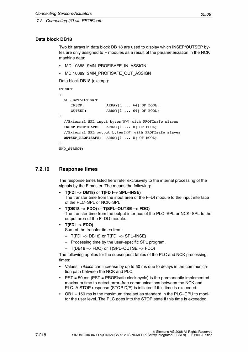
Connecting Sensors/Actuators
7.2 Connecting I/O via PROFIsafe
05.08
7-218© Siemens AG 2008 All Rights Reserved
SINUMERIK 840D sl/SINAMICS S120 SINUMERIK Safety Integrated (FBSI sl) – 05.2008 Edition
Data block DB18
Two bit arrays in data block DB 18 are used to display which INSEP/OUTSEP by-tes are only assigned to F modules as a result of the parameterization in the NCKmachine data:
� MD 10388: $MN_PROFISAFE_IN_ASSIGN
� MD 10389: $MN_PROFISAFE_OUT_ASSIGN
Data block DB18 (excerpt):
STRUCT
:
SPL_DATA:STRUCT
INSEP: ARRAY[1 ... 64] OF BOOL;
OUTSEP: ARRAY[1 ... 64] OF BOOL;
:
//External SPL input bytes(HW) with PROFIsafe slaves
INSEP_PROFISAFE: ARRAY[1 ... 8] OF BOOL;
//External SPL output bytes(HW) with PROFIsafe slaves
OUTSEP_PROFISAFE: ARRAY[1 ... 8] OF BOOL;
:
END_STRUCT;
7.2.10 Response times
The response times listed here refer exclusively to the internal processing of thesignals by the F master. The means the following:
� T(FDI –> DB18) or T(FD I–> SPL–INSE)The transfer time from the input area of the F–DI module to the input interfaceof the PLC–SPL or NCK–SPL
� T(DB18 –> FDO) or T(SPL–OUTSE –> FDO)The transfer time from the output interface of the PLC–SPL or NCK–SPL to theoutput area of the F–DO module.
� T(FDI –> FDO)Sum of the transfer times from:
– T(FDI –> DB18) or T(FDI –> SPL–INSE)
– Processing time by the user–specific SPL program.
– T(DB18 –> FDO) or T(SPL–OUTSE –> FDO)
The following applies for the subsequent tables of the PLC and NCK processingtimes:
� Values in italics can increase by up to 50 ms due to delays in the communica-tion path between the NCK and PLC.
� PST = 50 ms (PST = PROFIsafe clock cycle) is the permanently implementedmaximum time to detect error–free communications between the NCK andPLC. A STOP response (STOP D/E) is initiated if this time is exceeded.
� OB1 = 150 ms is the maximum time set as standard in the PLC–CPU to moni-tor the user level. The PLC goes into the STOP state if this time is exceeded.

Connecting Sensors/Actuators
7.2 Connecting I/O via PROFIsafe
05.08
7-219© Siemens AG 2008 All Rights ReservedSINUMERIK 840D sl/SINAMICS S120 SINUMERIK Safety Integrated (FBSI sl) – 05.2008 Edition
� 0...m * IPO: This time component only becomes applicable if delays are in-curred on the PLC side. In this case, in each subsequent IPO clock cycle, it isdetermined as to whether the PLC is ready to communicate again.
� OB40_INT is the maximum permissible time to initiate the interrupt on the NCKside up to execution of the PROFIsafe software and a ready signal to the NCK.The time is mainly determined by the run time (propagation time) of the F driverimplementation on the PLC side and the PLC user program to be run–throughin the OB40 context. These times typically lie in the vicinity of a few millisec-onds.
� The specified maximum times are theoretical values; it is extremely improbablethat they actually occur in practice.
Reason:
– It is improbable that the run time of the PLC–F driver is delayed – in theOB40 context – by the maximum time of 50 ms. The reason for this is thatthe interrupting organizational blocks (OB8x) only have such long run timesin extremely few cases.
– For the theoretical value, it would be necessary that two consecutive runs ofthe PLC–PROFIsafe master driver in the OB40 context are delayed by thepermitted maximum of 50 ms – this is extremely improbable.
– The maximum time of 150 ms for the user program is not reached in any ofthe applications relevant in practice.
PLC processing times
Time:: T(FDI–>DB18)
Formula 2 * PST + 1 * OB1
Max. times 2 * 50 ms + 1 * 150 ms 250 ms
Typical times 1) 2 * 16 ms + 1 * 30 ms 62 ms
Time:: T(DB18–>FDO)
Formula 2 * PST + 1 * OB1
Max. times 2 * 50 ms + 1 * 150 ms 250 ms
Typical times 1) 2 * 16 ms + 1 * 30 ms 62 ms
Time:: T(FDI–>FDO)
Formula 4 * PST + 2 * OB1
Max. times 4 * 50 ms + 2 * 150 ms 500 ms
Typical times 1) 4 * 16 ms + 2 * 30 ms 124 ms
1) Typical times: PST = 16 ms; OB1 = 30 ms
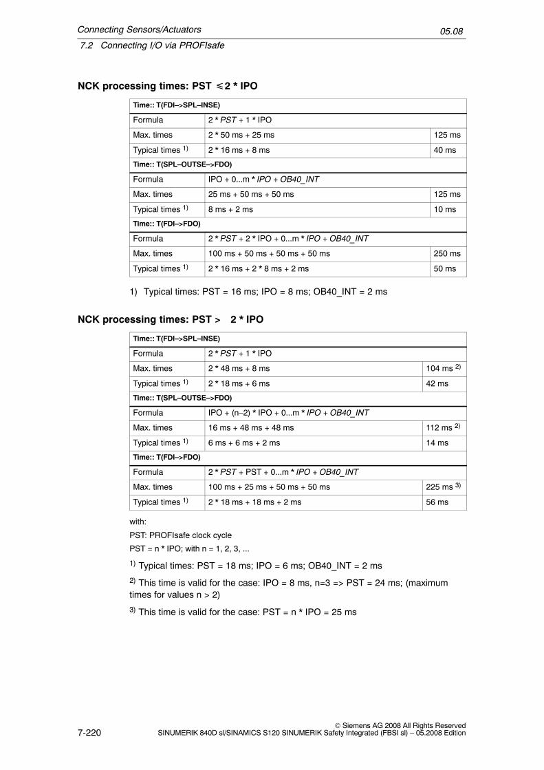
Connecting Sensors/Actuators
7.2 Connecting I/O via PROFIsafe
05.08
7-220© Siemens AG 2008 All Rights Reserved
SINUMERIK 840D sl/SINAMICS S120 SINUMERIK Safety Integrated (FBSI sl) – 05.2008 Edition
NCK processing times: PST �2 * IPO
Time:: T(FDI–>SPL–INSE)
Formula 2 * PST + 1 * IPO
Max. times 2 * 50 ms + 25 ms 125 ms
Typical times 1) 2 * 16 ms + 8 ms 40 ms
Time:: T(SPL–OUTSE–>FDO)
Formula IPO + 0...m * IPO + OB40_INT
Max. times 25 ms + 50 ms + 50 ms 125 ms
Typical times 1) 8 ms + 2 ms 10 ms
Time:: T(FDI–>FDO)
Formula 2 * PST + 2 * IPO + 0...m * IPO + OB40_INT
Max. times 100 ms + 50 ms + 50 ms + 50 ms 250 ms
Typical times 1) 2 * 16 ms + 2 * 8 ms + 2 ms 50 ms
1) Typical times: PST = 16 ms; IPO = 8 ms; OB40_INT = 2 ms
NCK processing times: PST > 2 * IPO
Time:: T(FDI–>SPL–INSE)
Formula 2 * PST + 1 * IPO
Max. times 2 * 48 ms + 8 ms 104 ms 2)
Typical times 1) 2 * 18 ms + 6 ms 42 ms
Time:: T(SPL–OUTSE–>FDO)
Formula IPO + (n–2) * IPO + 0...m * IPO + OB40_INT
Max. times 16 ms + 48 ms + 48 ms 112 ms 2)
Typical times 1) 6 ms + 6 ms + 2 ms 14 ms
Time:: T(FDI–>FDO)
Formula 2 * PST + PST + 0...m * IPO + OB40_INT
Max. times 100 ms + 25 ms + 50 ms + 50 ms 225 ms 3)
Typical times 1) 2 * 18 ms + 18 ms + 2 ms 56 ms
with:
PST: PROFIsafe clock cycle
PST = n * IPO; with n = 1, 2, 3, ...
1) Typical times: PST = 18 ms; IPO = 6 ms; OB40_INT = 2 ms
2) This time is valid for the case: IPO = 8 ms, n=3 => PST = 24 ms; (maximumtimes for values n > 2)
3) This time is valid for the case: PST = n * IPO = 25 ms
Connecting Sensors/Actuators
7.2 Connecting I/O via PROFIsafe
05.08
7-221© Siemens AG 2008 All Rights ReservedSINUMERIK 840D sl/SINAMICS S120 SINUMERIK Safety Integrated (FBSI sl) – 05.2008 Edition
7.2.11 Functional boundary conditions
When connecting via SPL I/O using one safety–related bus (PROFIsafe), severalsecondary conditions and constraints must be taken into consideration when con-figuring and programming:
� Faults/errors in the PROFIsafe input devices (e.g. input signals that differ fromone another) cause the associated SPL input signals ($A_INSE(P)) to be de-leted (cleared). This initiates a STOP D/E.
� The external SPL input signals in the DB18 interface for the $A_INSEP vari-ables are transferred within the system. This means that programming is nolonger necessary in the user program. Only one signal state for both SPL chan-nels is transferred to the master from the PROFIsafe input peripherals.
� The external SPL output signals of the DB18 interface ($A_OUTSEP variables)are transferred within the system to the relevant PROFIsafe output modules.A signal state is transferred to the output modules via PROFIsafe.
� It may be necessary to use single–channel signals (signals that are presentonly in the PLC or only in the NCK) to change over external SPL outputs (e.g.braking control). These single–channel signals must also be made available tothe other program channel to align the logic and program synchronously. Directcommunications between the NCK and PLC–SPL via DB18 is a good way toachieve this.
� In each PROFIsafe cycle, the PROFIsafe layer generates a PROFIsafe tele-gram with the logically AND’ed SPL output data as F net (useful) data.
F modules
As far as the F modules that can be operated with a SINUMERIK 840D sl, the fol-lowing limitations apply:
� F modules with dynamic i parameters are not supported.
� The maximum possible F net data width for each F module is 64 bits.
� The value range for the F address of an F module is as follows: 1 – 65535D or1 – FFFFH
Note
Only ET 200 stations can be operated whose configuration is less than 244 byteslarge. If this rule is not observed, then PROFIsafe modules will no longer bedetected and Alarms 27220 and 27221 will be output. The size of the configurationcan be taken from the documentation of the ET 200 modules or using the ET 200configurator.
Connecting Sensors/Actuators
7.2 Connecting I/O via PROFIsafe
05.08
7-222© Siemens AG 2008 All Rights Reserved
SINUMERIK 840D sl/SINAMICS S120 SINUMERIK Safety Integrated (FBSI sl) – 05.2008 Edition
Axial SGE/SGA
I/O (F net data) of an F module cannot be connected to axial SGE/ SGA. They canonly be connected in the context of the SPL that must be installed for the purpose.
PLC SPL SGE/SGA
The basic PLC program automatically connects the I/O (F net data) of an F moduleto the SPL interface in data block DB18.
It is not possible to connect them in a PLC user program.

Connecting Sensors/Actuators
7.3 Safe programmable logic (SPL)
05.08
7-223© Siemens AG 2008 All Rights ReservedSINUMERIK 840D sl/SINAMICS S120 SINUMERIK Safety Integrated (FBSI sl) – 05.2008 Edition
7.3 Safe programmable logic (SPL)
7.3.1 Basic principles
Function
These signals must be logically combined (interlocked) in a safety–related, freelyprogrammable form in order to be able to flexibly process safety–related externalprocess signals and safety–related internal input and output signals. The ”SafeProgrammable Logic” (SPL) handles this task as an integral system component.
Features:
� Logic operations implemented by the user are cyclically processed.
� Instructions are effective in all operating modes.
� The PLC program immediately starts to execute the instructions after the con-trol has booted.
� The SGE/SGA must be supplied by the machine manufacturer – both in thedrive monitoring channel as well as in the NCK monitoring channel.
� The NCK–SPL is written as ASUB using the CNC function synchronous ac-tions. The PLC–SPL is written as PLC user program.
In order to check that the two SPLs (PLC and NCK) are functioning, the systemprogram arranges cyclic data comparison between the PLC and NCK.
Max. 64 safety–related sensors
can be directly connected
(e.g.: mode switch, light
barriers, Emergency Stop,...)
Max. 64 safety–related
actuators can be connected
(e.g.: protective door
interlocking, motor brakes, ...)
Crosswise result and
data comparison
NCK–SPL
PLC–SPL
SGE
SGE SGA
SGA
Fig. 7-21 Safe programmable logic

Connecting Sensors/Actuators
7.3 Safe programmable logic (SPL)
05.08
7-224© Siemens AG 2008 All Rights Reserved
SINUMERIK 840D sl/SINAMICS S120 SINUMERIK Safety Integrated (FBSI sl) – 05.2008 Edition
Crosswise data comparison
Data is cyclically exchanged between the PLC and NCK to check the correct func-tioning of the two SPLs (PLC and NCK). Just the same as the comparison be-tween the NCK and the drive, it cross–checks the signals that arrive at the SPL,the safety–related signals generated by the SPL as well as internal markers.
The discrepancy time for the crosswise data comparison of SPL variables is per-manently set to 1 s (or 10 s $A_CMDSI).
The following signals are included in the crosswise data comparison between theNCK and the PLC:
Table 7-3 Signals for crosswise data comparison
NCK PLC
External SPL inputs $A_INSE[1 ... 64] SPL_DATA.INSEP[1...64]
External SPL outputs $A_OUTSE[1 ... 64] SPL_DATA.OUTSEP[1...64]
Internal SPL inputs $A_INSI[1 ... 64] SPL_DATA.INSIP[1...64]
Internal SPL outputs $A_OUTSI[1 ... 64] SPL_DATA.OUTSIP[1...64]
SPL markers $A_MARKERSI[1 ... 64] SPL_DATA.MARKER-SIP[1...64]
”SPL commissioning phasecompleted”
$MN_PREVENT_SYN-ACT_LOCK[0,1]
DB18.DBX36.0
”Stop for SPL–crosswise datacomparison error”
$MN_SPL_STOP_MODE DB18.DBX36.1
If an error is detected on one of the monitored signals, this is indicated using Alarm27090 and the configured stop response (STOP D/E) is initiated.
If a difference is detected, Alarm 27090 ”Error for crosswise data comparisonNCK–PLC” is output. In addition, a STOP D/E is initiated if the SPL commissioningphase is defined as having been completed.
The criterion ”commissioning phase completed” is derived from the NCK–MD$MN_PREVENT_SYNACT_LOCK[0,1] in the NCK. If one of the two field entries isnot equal to 0, ”commissioning phase completed” is set internally by the crosswisedata comparison. On the PLC side, this requirement is entered usingDB18.DBX36.0. If this bit is set to ”1”, then the commissioning phase is consideredto have been completed. An SPL crosswise data comparison error only results in astop response after the SPL commissioning phase has been completed.
The stop response for an SPL crosswise data comparison error is set in the NCKusing NCK–MD $MN_SPL_STOP_MODE. If the MD value is 3, for an SPL cross-wise data comparison error, a STOP D is initiated – for an MD value of 4, a STOPE is initiated. On the PLC side, this stop response is entered using DB18.DBX36.1.If this bit is set to ”1”, for an SPL crosswise data comparison error, a STOP E isinitiated – otherwise a STOP D.
Any changes to data on the NCK and PLC side do not take effect until after power on.
Connecting Sensors/Actuators
7.3 Safe programmable logic (SPL)
05.08
7-225© Siemens AG 2008 All Rights ReservedSINUMERIK 840D sl/SINAMICS S120 SINUMERIK Safety Integrated (FBSI sl) – 05.2008 Edition
Clearing the external SPL outputs for SPL system errors
If communications between the NCK and PLC with reference to the SPL crosswisedata comparison, are interrupted, then all external SPL output signals($A_OUTSE/$A_OUTSEP) are deleted with a delay of 5 s.
This state occurs if no data exchange or crosswise data comparison occurs be-tween the NCK and PLC for one second. This is due to the fact that
– the one second limit of the user cycle limit in the PLC (OB1 cycle) was ex-ceeded.
– a system error has occurred. The NCK or PLC system software no longer runsdue to a system error – therefore interrupting communications.
Behavior of the NCK
The specified timer of 5 s is started if Alarm 27092 ”Communication interrupted forcrosswise data comparison NCK–SPL, error detected by %1” is initiated. This isindependent of which component (NCK or PLC) interrupted the alarm.
The system variable $A_STATSID, bit 29 = 1 is used to indicate to the SPL userthat this timer has been started. This means that he has a possibility of initiatingplant/system–specific actions before the system deletes (clears) the output.
After this time has expired, the system deletes the external SPL outputs. The sta-tus variable $A_STATSID, bit 29 remains set. When reading–back the external out-puts in the NCK–SPL via the system variable $A_OUTSE, ”0” is read correspond-ing to the actual output status.
Behavior of the PLC
If, on the PLC side, it is detected that the communication timeout has been ex-ceeded, then a timer is started with 5 s.
After this time has expired, the PLC goes into Stop (by calling an SFC46). Thisstate can only be exited using a power on.
After the 5 s timer has expired, the PLC outputs its own message for diagnosticpurposes. At the same time, an entry with the same significance is located in thediagnostics buffer.
Using the status signal DB18.DBX119.5, the SPL programmer and the NCK is pro-vided with the information that the timer was started. This means that he has thepossibility of initiating system–specific actions before the PLC goes into the stopcondition.
Note
In order to achieve the shortest possible response time, the system variable$A_STATSID, bit 29 and the status signal DB18.DBX119.5 must be evaluated inthe SPL in order to bring, as far as possible, the SPL–SGA into a safe state(cleared SPL–SGA).

Connecting Sensors/Actuators
7.3 Safe programmable logic (SPL)
05.08
7-226© Siemens AG 2008 All Rights Reserved
SINUMERIK 840D sl/SINAMICS S120 SINUMERIK Safety Integrated (FBSI sl) – 05.2008 Edition
Limitations
The user must take into consideration the following points regarding the functioningof the crosswise data comparison:
� Both channels (NCK/PLC) must execute the same logic.
� Do not implement any response sequences or sequence controllers that areexternally controlled using short input pulses. This is because short pulses ofthis type may only be sent and processed in one channel because of samplingeffects.
� Unused inputs/outputs/markers of the SPL must be assigned the default value= 0; single–channel use of individual bits for non–safety relevant purposes isnot permissible.
� External STOPs must be enabled (they are also used internally) and can beextracted from the SPL if required. The ”external STOP A” must be parameter-ized at the SPL interface for all safety axes using MD$MA_SAFE_EXT_STOP_INPUT[0]. If this condition is not fulfilled, then Alarm27033 is output.
� Crosswise data comparison checks whether the ”commissioning phase” hasbeen completed. If errors are detected in the crosswise data comparison, a”STOP D/E” is triggered on the NCK and drive depending on this criterion. If thecommissioning phase has not been completed after booting, Alarm 27095 ”SPLprotection not activated” is repeatedly displayed (every 3 hours).
Process
Motor
Comparator
Data
Comparator
Data
Drive monitoring channel
System
Interface
Interface
NCK–SPL
NCK signal processing
NCKSGE/SGAsignals
PLC–SPL
NC/PLCinterface:
Axis/
spindle DB
PLC signal processing
PROFIsafe
ExternalSGE/SGA
InternalSGE/SGA
Bus
NCK monitoring channel
CDC CDC CDC
PR
OF
Isaf
eP
RO
FIs
afe
Fig. 7-22 Communications between the NCK–drive–PLC components

Connecting Sensors/Actuators
7.3 Safe programmable logic (SPL)
05.08
7-227© Siemens AG 2008 All Rights ReservedSINUMERIK 840D sl/SINAMICS S120 SINUMERIK Safety Integrated (FBSI sl) – 05.2008 Edition
� In the case of a crosswise data comparison error, no system response is initi-ated regarding the SGE/SGA processed by the SPL. Users must implementthis themselves. The only exception is when a system error is detected as wasdescribed above.
7.3.2 Synchronized actions for Safety Integrated
Motion–synchronizing actions (or ”synchronizing actions” for short) are instructionsprogrammed by the user, which are evaluated in the interpolation cycle of the NCKin synchronization with the execution of the part program. If the condition pro-grammed in the synchronized action is fulfilled (logical expression) or if none isspecified, then actions assigned to the instruction are activated in synchronismwith the remainder of the part program run.
Description
The number of programmable synchronized action blocks depends entirely on theconfigurable number of synchronized action elements. The number of storage ele-ments for general motion–synchronizing actions (synchronizing action elements) isdefined in machine data MD 28250: MM_NUM_SYNC_ELEMENTS.
The memory management is listed separately in order to be able to handle syn-chronized actions for SAFE.SPF independently.MD 28251: $MC_MM_NUM_SAFE_SYNC_ELEMENTS is used to configure thememory for the safety synchronized action elements.All modal synchronized actions that are programmed in the sub–program/_N_CST_DIR/_N_SAFE_SPF retrieve their elements from this memory area.In order to determine the required for synchronized action elements, at the startand at the end of SAFE.SPF, system variables $AC_SAFE_SYNA_MEM can beread. The difference between these values is then the number of synchronized ac-tion elements required. This value plus a possible reserve must be entered into MD28251: $MC_MM_NUM_SAFE_SYNC_ELEMENTS.
References: /FBSY/ Description of Functions, Synchronized Actions
Connecting Sensors/Actuators
7.3 Safe programmable logic (SPL)
05.08
7-228© Siemens AG 2008 All Rights Reserved
SINUMERIK 840D sl/SINAMICS S120 SINUMERIK Safety Integrated (FBSI sl) – 05.2008 Edition
7.3.3 NCK–SPL program
Description
The NCK–SPL program is written as an NC program (ASUB) with synchronizedactions.
Features
The NCK–SPL program has the following features:
� The program can be started manually with NC START during commissioning.
� The following applies once the program has been started:
– The synchronous actions assigned an ID No. are cyclically executed in theIPO clock cycles (modal)
– The synchronous actions assigned the keyword IDS remain active even af-ter the operating mode has been changed or NC–STOP/NC RESET
– In order to check the program, the status of the active synchronous actions(operating area ”Machine”, soft key ”Synchronous actions”) can be dis-played.
– The program can be modified during commissioning. It must then be re–started.
– The NCK–SPL program is saved in the NCK path_N_CST_DIR as sub–rou-tine ”_N_SAFE_SPF” (HMI view: standard cycles/SAFE.SPF).Other sub–routine names are not permitted.
� The images of the PLC safety variables ($A_INSIP(D), $A_OUTSIP(D), $A_IN-SEP(D), $A_OUTSEP(D), $A_MARKERSIP(D) ) are required for the simulation(on the NC side) of an SPL. These can be used to develop the SPL step–by–step. They can only be read by the NCK.
Protective mechanisms
� The synchronous action IDs used for the NCK–SPL are protected from beinginfluenced by the PLC or other programs using MD $MN_PREVENT_SYN-ACT_LOCK. To activate the protection, the number range of the synchronousaction IDs used in the SPL program must be entered into the two fields of ma-chine data $MN_PREVENT_SYNACT_LOCK. It is then no longer possible tochange these synchronous actions (CANCEL, LOCK have no effect) once_N_SAFE_SPF has been started.

Connecting Sensors/Actuators
7.3 Safe programmable logic (SPL)
05.08
7-229© Siemens AG 2008 All Rights ReservedSINUMERIK 840D sl/SINAMICS S120 SINUMERIK Safety Integrated (FBSI sl) – 05.2008 Edition
� System variables $A_OUTSI, $A_OUTSID, $A_OUTSE, $A_OUTSED,$A_MARKERSI, $A_TIMERSI and $A_CMDSI are protected from being writtento by programs other than the NCK–SPL (/_N_CST_DIR/_N_SAFE_SPF). If anerror occurs, Alarm 17070 ”Channel %1 block %2 data item write–protected” isoutput.
� A reference checksum is calculated when booting by the NCK–SPL(/_N_CST_DIR/_N_SAFE_SPF) – it is entered into the program as a comment:
Example: ; SAFE_CHECKSUM = 000476bbH
The checksum is then cyclically re–calculated and compared with the referencechecksum. If a deviation is detected, Alarm 27093 ”Checksum error NCK–SPL,%1, %2, %3” is output.
� The system variables $A_INSIP(D), $A_OUTSIP(D), $A_INSEP(D), $A_OUT-SEP(D) and $A_MARKERSIP(D) are only accessible during the commissioningphase.
If NCK–SPL execution is interrupted for any reason or the SI system variables arechanged by another program, then this is detected by the cyclic crosswise datacomparison with the PLC.
Table 7-4 Response to SPL errors
Event MD 11500 $MN_PREVENT_SYNACT_LOCK[m,n] equal to 0
MD 11500 $MN_PREVENT_SYNACT_LOCK[m,n] not equal to 0
Crosswise data comparisonNCK–PLC identifies an error
Alarm 27090 is triggered Alarm 27090 is triggered and in addi-tion, STOP D/E is triggered
SPL program file is to be changed(written, deleted, re–named, edited)
No response Alarm 27093 is triggered
!Warning
The protective mechanisms that prevent changes to the NCK–SPL file and theNCK–SPL instructions (statements) are only completely effective ifMD $MN_PREVENT_SYNACT_LOCK[0,1] is set to the value range of thesynchronous action IDs used in the NCK–SPL.
The machine construction OEM must ensure that the protective mechanisms areactivated no later than after the completion of the acceptance test and the values,set in MD $MN_PREVENT_SYNACT_LOCK[0,1] are documented in theacceptance report.
After commissioning has been completed, the access rights to the SAFE.SPF filemust be set to the correct access level for writing/reading/deleting accessoperations (manufacturer or service).

Connecting Sensors/Actuators
7.3 Safe programmable logic (SPL)
05.08
7-230© Siemens AG 2008 All Rights Reserved
SINUMERIK 840D sl/SINAMICS S120 SINUMERIK Safety Integrated (FBSI sl) – 05.2008 Edition
As long as the protective mechanisms for the NCK–SPL have not been activated(MN_PREVENT_SYNACT_LOCK[0.1] equal to 0), Alarm 27095 is displayed whenthe crosswise data comparison between the NCK and the PLC starts. This alarmcan be acknowledged with the NCK key so that the SPL can be commissioned.
Note
The SPL program must be addressed using upper case letters. Alarm 27097 isoutput if this is not observed.
7.3.4 Starting the SPL
The NCK–SPL is active after the control has booted, if at least
1. The functions SBH/SG and ”external STOPs” have been enabled for at leastone axis using $MA_/$MD_SAFE_FUNCTION_ENABLE,
2. One of the NCK–SPL interfaces is used.This means that an axial SGE/SGA was parameterized at one of the SPL inter-faces using its assignment MD.
In this case, the ”external STOP A” must be parameterized at the SPL interface forall of the axes that use Safety Integrated.
In addition, the following machine data must be set for an error–free ASUB startafter the NCK and the PLC have booted:
3. $MN_ASUP_START_MASK=7:ASUB can be started in all operating states of the NC (RESET/JOG/not all axesreferenced/read–in active).
4. $MN_ASUP_START_PRIO_LEVEL=1:Interrupt priority, from which MD $MN_ASUP_START_MASK becomes active.
Other actions to be executed:
5. A PLC–SPL has to be created and integrated into the PLC user program
6. An NCK–SPL has to be created and loaded into the directory /_N_CST_DIRinto the file /_N_SAFE_SPF (= MMC view standard cycles/SAFE.SPF)
Note
It is not permissible that any alarms are present for an ASUB start.

Connecting Sensors/Actuators
7.3 Safe programmable logic (SPL)
05.08
7-231© Siemens AG 2008 All Rights ReservedSINUMERIK 840D sl/SINAMICS S120 SINUMERIK Safety Integrated (FBSI sl) – 05.2008 Edition
SPL start without axial safety enable
When the machine is being commissioned, the SPL must be started withoutenabling axis–specific safety–related functions.
It is therefore possible to handle general machine functions (hydraulics,Emergency Stop) before the axis is commissioned.This is only possible in the commissioning state of the SPL ($MN_PRE-VENT_SYNACT_LOCK[0,1]==0 and DB18.DBX36.0==0).This state is displayed when the SPL starts using Alarm 27095 ”%1 SPL protectionnot activated”.
If an attempt is made to start the SPL in the protective state (after commissioninghas been completed) without the axial safety function having been activated, thenAlarm 27096 is output. The SPL is started if the SPL crosswise data comparison isnot activated.
7.3.5 Starting the NCK–SPL using the PROG_EVENT mechanism
The NCK–SPL can also be started using the PROG_EVENT mechanism.
The PROG_EVENT.SPF cycle (saved under manufacturer cycles ..\DH\CMA.DIR)is started when a specific event occurs (event–controlled program call).
Using the machine data MD 20108 $MC_PROG_EVENT_MASK, for thisPROG_EVENT mechanism, certain events are enabled on a specific channel–for–channel basis which then start the cycle.
The following events can be activated as start condition:
� Start of a part program bit 0 == 1
� End of a part program bit 1 == 1
� Operator panel reset bit 2 == 1
� Boot bit 3 == 1
The start condition when booting (bit 3 ==1) must be active in order to start theNCK–SPL (SAFE.SPF) via PROG_EVENT.SPF.

Connecting Sensors/Actuators
7.3 Safe programmable logic (SPL)
05.08
7-232© Siemens AG 2008 All Rights Reserved
SINUMERIK 840D sl/SINAMICS S120 SINUMERIK Safety Integrated (FBSI sl) – 05.2008 Edition
Note
When starting the NCK–SPL (SAFE.SPF), it is important that the PROG_EVENTmechanism was started through channel 1. This must be taken into accountwhen parameterizing the channel–specific data MD 20108$MC_PROG_EVENT_MASK.
Using the system variable $P_PROG_EVENT, in PROG_EVENT.SPF it can beinterrogated as to which event activated the call:
� Start of a part program $P_PROG_EVENT == 1
� End of a part program $P_PROG_EVENT == 2
� Operator panel reset $P_PROG_EVENT == 3
� Boot $P_PROG_EVENT == 4
For the PROG_EVENT.SPF cycle, MD 11602 $MN_ASUP_START_MASK (rec-ommended setting = 7H) is taken into account; this can be used to ignore reasonsfor initiating a stop to run the sequence. The setting in MD 11604$MN_ASUP_START_PRIO_LEVEL is not relevant for PROG_EVENT.SPF.
Example for PROG_EVENT.SPF
; ––––––––––––––––––––––––––––––––––––––––––––––––––––––––
; Event–controlled program call
; PROG_EVENT.SPF under \DH\CMA.DIR
; ––––––––––––––––––––––––––––––––––––––––––––––––––––––––
;;;
In machine data MD 20108: PROG_EVENT_MASK can be set channel–spe-cifically which of the following events will enable the user program:
; ( ) Start of the part program ––> bit 0 == 1
; ( ) End of the part program ––> bit 1 == 1
; ( ) Operator panel reset ––> bit 2 == 1
; (x) Run–up ––> bit 3 == 1
; –––––––––––––––––––––––––––––––––––––––––––––––––––––––
;;
Using the system variable $P_PROG_EVENT, it can be interrogated as towhich event activated the call:
; ( ) Start of the part program ––> $P_PROG_EVENT == 1
; ( ) End of the part program ––> $P_PROG_EVENT == 2
; ( ) Operator panel reset ––> $P_PROG_EVENT == 3
; (x) Run–up ––> $P_PROG_EVENT == 4
;

Connecting Sensors/Actuators
7.3 Safe programmable logic (SPL)
05.08
7-233© Siemens AG 2008 All Rights ReservedSINUMERIK 840D sl/SINAMICS S120 SINUMERIK Safety Integrated (FBSI sl) – 05.2008 Edition
;–––––––––––––––––––– Cycle definition ––––––––––––––––––
; Suppress single block, display
;––––––––––––––––––––––––––––––––––––––––––––––––––––––––
N100 PROC PROG_EVENT SBLOF DISPLOF
;
; NCK–SPL start
; –––––––––––––––––––––––––––––––––––––––––––––––––––––––
N200 IF ($P_PROG_EVENT == 4); Boot query
N300 CALL ”/_N_CST_DIR/_N_SAFE_SPF”
N400 ENDIF
N500 ...
N600 ...
N700 M17 ; End of cycle
The part program SAFE.SPF is called if the system variable check$P_PROG_EVENT indicated that the part program call PROG_EVENT.SPF wascalled when the control system booted.
Example for SAFE.SPF
A simple example for SAFE.SPF will now be shown that is started usingPROG_EVENT when the system boots and includes steady–state synchronousactions.
; File: SAFE.SPF
=============
; Definitions
DEFINE STOP_A_DISABLE AS $A_OUTSI[1]
DEFINE STOP_C_DISABLE AS $A_OUTSI[2]
DEFINE STOP_D_DISABLE AS $A_OUTSI[3]
;
DEFINE STOP_A_EXT AS $A_INSE[6]
DEFINE STOP_C_EXT AS $A_INSE[7]
DEFINE STOP_D_EXT AS $A_INSE[8]
DEFINE STOP_A_XT AS $A_INSE[9]
;
; Program section
N10 IDS=01 DO STOP_A_DISABLE=STOP_A_EXT
N20 IDS=02 DO $A_OUTSE[1]=NOT $A_OUTSE[1]
N30 M17
Connecting Sensors/Actuators
7.3 Safe programmable logic (SPL)
05.08
7-234© Siemens AG 2008 All Rights Reserved
SINUMERIK 840D sl/SINAMICS S120 SINUMERIK Safety Integrated (FBSI sl) – 05.2008 Edition
7.3.6 Starting the NCK–SPL from the PLC user program
Program start
The NCK–SPL can also be started from the PLC user program. As soon as theNCK–SPL has been started, the crosswise data comparison is activated in thesystem program (NCK and PLC basic program).The NCK–SPL program must be started as an ASUB. To do this, the interruptnumber and channel must first be assigned via FB4 using the ASUB (asynchro-nous sub–routine) function via parameter PIService=”PI.ASUB”.As soon as FB4 has been successfully run (output parameter ”Done”=TRUE) theprogram is executed via FC9 ”ASUB” [asynchronous sub–routine].
Starting the PLC–SPL
The PLC–SPL in conjunction with FB4/FC9 has started if the FC9 has signaledsuccessful execution and has displayed that the end of SAFE.SPF has beenreached. This is displayed using a signal in SAFE.SPF (e.g. $A_PLCSIOUTvariable, M function) or SPL status bit 13 (DB18.DBX137.5). Only then may thePLC–SPL be started to ensure that both SPLs run in synchronism and thereforethe axial monitoring channels are synchronously supplied.
Parameterizing FB 4
FB4 may only be started in the cyclic mode (OB 1).
Table 7-5 Parameterizing FB 4
Signal Type Value range Description
Reg
PIService ANY PI.ASUP Assign interrupt
Unit INT 1 to 10 [1] Channel
WVar1 INT [1] Interrupt number
WVar2 INT [1] Priority
WVar3 INT 0/1 [0] LIFTFAST
WVar4 INT 0/1 [0] BLSYNC
Addr1 STRING ’/_N_CST_DIR/’ NCK–SPL path name
Addr2 STRING ’_N_SAFE_SPF’ NCK–SPL program name
[values in brackets are standard values required for the call]
Connecting Sensors/Actuators
7.3 Safe programmable logic (SPL)
05.08
7-235© Siemens AG 2008 All Rights ReservedSINUMERIK 840D sl/SINAMICS S120 SINUMERIK Safety Integrated (FBSI sl) – 05.2008 Edition
Parameterizing FC 9
Table 7-6 Parameterizing FC9
Signal Type Type Value range Comment
Start I Bool
ChanNo I Int 1 to 10 [1] No. of the NC channel
IntNo I Int 1 – 8 [1] Interrupt No.
Active O Bool 1 = Active
Done O Bool 1 = ASUB completed
Error O Bool
[values in brackets are standard values required for the call]
7.3.7 Diagnostics/commissioning
The system variables $A_INSIP(D), $A_OUTSIP(D), $A_INSEP(D) and $A_OUT-SEP(D), and $A_MARKERSIP(D) are only used for diagnostics and commission-ing the NCK–SPL. These system variables represent the input data for crosswisedata comparison on the PLC side. They are updated every IPO cycle. They canalso be used to access the crosswise data comparison on the PLC side from theNC. This helps when commissioning the SPL:
� Crosswise data comparison function can be temporarily bypassed
� NCK–SPL can be simulated to the process and to the NCK monitoring channelTo do this, the relevant PLC images are written to the variables $A_OUTSEDand $A_OUTSID as long as there is no NCK–SPL. This means that the NCK–SPL can be commissioned step–by–step. This data may only be accessed dur-ing the commissioning phase.
In order to allow the SPL to be commissioned without the crosswise data compari-son function constantly responding, the following ”minimum NCK–SPL” can beinstalled in this phase:
; Simulate external SPL interface
IDS = 03 DO $A_OUTSED[1] = $A_OUTSEPD[1]
IDS = 04 DO $A_OUTSED[2] = $A_OUTSEPD[2]
; Simulate internal SPL interface
IDS = 07 DO $A_OUTSID[1] = $A_OUTSIPD[1]
IDS = 08 DO $A_OUTSID[2] = $A_OUTSIPD[2]
; Emulate PLC markers (for all markers used in the PLC)
IDS = 09 DO $A_MARKERSID[1] = $A_MARKERSIPD[1]
IDS = 10 DO $A_MARKERSID[2] = $A_MARKERSIPD[2]
; End of program
M17

Connecting Sensors/Actuators
7.3 Safe programmable logic (SPL)
05.08
7-236© Siemens AG 2008 All Rights Reserved
SINUMERIK 840D sl/SINAMICS S120 SINUMERIK Safety Integrated (FBSI sl) – 05.2008 Edition
These instructions simulate the output interfaces of the NCK–SPL and therefore”short–circuit” the crosswise data comparison.
!Warning
The logic used in this phase has a single channel structure and is therefore notsafe!
The described minimum NCK–SPL must be replaced by a full NCK–SPL withoutany access to $A_INSIP(D), ..., $A_MARKERSIP(D) when the PLC side iscompleted!
Additional diagnostic support:
� $A_STATSID: A value not equal to 0 means that an error has occurred in thecrosswise data comparison. The error numbers are selected in the same wayas on the PLC side (see Chapter 7.3.11).
� $A_CMDSI[n]: n=1: 10x change timer value for long forced checking procedurepulses and/or single–channel test stop logic.
� $A_LEVELSID: Indicates how many signals have different signal levels on theNCK and PLC sides that can be presently detected.
� In addition, other NC variables or free R parameters can be written to monitorinternal states of the SPL.
The following applies to all system variables of the NCK–SPL outputs:They can be written from and read back to the SPL program.
7.3.8 Safe software relay
The standard SPL block ”safety software relay” is designed to meet the require-ments of an Emergency Stop function with safe programmable logic. However, itcan also be used to implement other similar safety functions, e.g. to control a pro-tective door.

Connecting Sensors/Actuators
7.3 Safe programmable logic (SPL)
05.08
7-237© Siemens AG 2008 All Rights ReservedSINUMERIK 840D sl/SINAMICS S120 SINUMERIK Safety Integrated (FBSI sl) – 05.2008 Edition
OR
AND
AND
Timer1
Timer2
Timer3
A0
A1
A2
A3
E1
I2
E3
t4
AND
CMP>=
t4i
TM1
Q1
Q2
TI1
TI2
TI3
E_AND
Time measurement –rising to falling edge
Fig. 7-23 Function diagram of the ”safety relay”
The description is provided in the following:
Three shutdown inputs E1 to E3 If one of these inputs is set to 0, direct output A0 is setto 0. Outputs A1 toA3 switch with the delay of timer1–3. If one of these inputs is not used, then it is inter-nally set to ”1” as static signal.One of these inputs must also be used to initiate testoperation of the safety relay (forced checking proce-dure).

Connecting Sensors/Actuators
7.3 Safe programmable logic (SPL)
05.08
7-238© Siemens AG 2008 All Rights Reserved
SINUMERIK 840D sl/SINAMICS S120 SINUMERIK Safety Integrated (FBSI sl) – 05.2008 Edition
Two acknowledge inputs Q1 andQ2
Q1 must be supplied with the signal from the realacknowledge button.Q2 is only used to automatically acknowledge thesafety software relay as part of the forced checkingprocedure. The software relay itself does not have tobe subject to a forced checking procedure. However, ifthe Emergency Stop function is executed and if exter-nal actuators have be subject to a forced checkingprocedure, if the relay drops out during the EmergencyStop test, then it can be acknowledged using Q2 (in adefined time window, refer to TM1). This input mustalso be connected with a safety system variable (evenif the signal is not used) – preferably with a$A_MARKERSI – in order to detect that this acknowl-edge signal is available as steady–state signal in thecrosswise data comparison with the PLC. The associ-ated comparison data in the PLC must have a steady–state 0 signal level (error detection using differentstates of the particular SPL marker for the PLC andNCK).
Three timer initialization valuesTI1 to TI3
The times after which outputs A1 to A3 are switched to0 at a negative edge in output signal A0 are definedhere.
One timer limit value TM1 This limit value is used to define the maximum timethat the shutdown inputs E1 to E3 (and their AND logicoperation) may have been at a 0 signal level so thatthey can still be acknowledged using Q2. This there-fore guarantees that Q2 can only be effective as auto-matic acknowledgment for the forced checking proce-dure within a defined time window after the relay hasdropped out (after it has been de–energized). It is notpermissible that Q2 is used to acknowledge a ”real”shutdown.
Four output values A0 to A3 A0 supplies the result of ANDing E1 to E3 without anydelay. Outputs A1 to A3 supply the same result for pos-itive edges of A0; for negative edges, the results aredelayed by the timer initialization TI1 to TI3.A0 to A3 do not produce a result after booting until anacknowledgment has been received via Q1.
Initialization in the part program
The connections for the function block are defined when initialized. The input andoutput quantities of the function block are assigned to the required system vari-ables ($A_MARKERSI, $A_INSE, $A_OUTSE,...). The following functions must becalled:

Connecting Sensors/Actuators
7.3 Safe programmable logic (SPL)
05.08
7-239© Siemens AG 2008 All Rights ReservedSINUMERIK 840D sl/SINAMICS S120 SINUMERIK Safety Integrated (FBSI sl) – 05.2008 Edition
SIRELIN: This language command assigns the input quantities Q1, Q2, E1, E2and E3 to the safety relay x (x = 1..4). The return value contains the number of thefirst incorrect parameter; a value of 0 indicates that the parameter assignment iscorrect.
Syntax: SIRELIN(x,status,”Q1”,”Q2”,”E1”,”E2”,”E3”)
The transfer parameters Q1 to E3 are strings and must therefore be entered inquotation marks (” ”). The following system variables are permissible as inputquantities:$A_MARKERSI[ ]$A_INSE[ ]$A_INSI[ ]$A_OUTSE[ ]$A_OUTSI[ ]
E2 and E3 are optional. If these parameters are not entered, the relevant inputsare set to ”1” (static signal).
SIRELOUT: This language command assigns the output quantities A0, A1, A2 andA3 to safety relay x (x = 1..4). The return value contains the number of the firstincorrect parameter; a value of 0 indicates that the parameter assignment is cor-rect.
Syntax: SIRELOUT(x,status,”A0”,”A1”,”A2”,A3”)
The transfer parameters A0 to A3 are strings and must therefore be entered inquotation marks (” ”). The following system variables are permissible as outputquantities:$A_MARKERSI[ ]$A_OUTSE[ ]$A_OUTSI[ ]$A_PLCSIOUT[ ]
A1 to A3 are optional. If these parameters are not specified, then the correspond-ing outputs are not supplied. However, if A1 is specified, the initialization value fortimer 1 (TI1) must also be parameterized via SIRELTIME. The same applies for A2and timer 2 (TI2) and A3 and timer 3 (TI3).
SIRELTIME: This language command assigns the times – for the timers required –to safety relay x (x = 1..4). These include the timer limit value TM1 and the timerinitialization values TI1, TI2 and TI3. The return value contains the number of thefirst incorrect parameter; a value of 0 indicates that the parameter assignment iscorrect.
Syntax: SIRELTIME(x,status,TM1,TI1,TI2,TI3)
Transfer parameters TM1 to TI3 are REAL numbers (timers in seconds). TI1 to TI3are optional. If these parameters are not specified, the corresponding outputs A1to A3 are not supplied. However, if TI1 is specified, output A1 must also be para-meterized via SIRELOUT. The same applies for TI2 and A2 and TI3 and A3.

Connecting Sensors/Actuators
7.3 Safe programmable logic (SPL)
05.08
7-240© Siemens AG 2008 All Rights Reserved
SINUMERIK 840D sl/SINAMICS S120 SINUMERIK Safety Integrated (FBSI sl) – 05.2008 Edition
Note
� The initialization language commands must be directly included in the partprogram (e.g. SAFE.SPF); they may not be used in synchronized actions! Ifthis condition is violated, Alarm 12571, ”Channel 1 Block %2 %3 not permittedin motion synchronizing action” is triggered.
� As described above, there is an interdependency between the number of theoptional parameters for the language commands SIRELTIME and SIRELOUT.This interdependency is checked in the language command that comes later inthe part program sequence. If, for example, A2 is no longer parameterized inSIRELOUT, but TI2 is specified in SIRELTIME, then this parameter is identifiedas being incorrect!
Cyclic sequence
The correctly timed call in the SPL is made using the language command SIRE-LAY. A calling parameter is not required in the cyclic section except to select thedesired relay x (x = 1.4). Initialization must be carried out beforehand. If this is notcorrectly done, then this is indicated in the return value of the language commandSIRELAY. The cyclic section must be integrated in the synchronized actions of theSPL.
Syntax: status = SIRELAY(x)
The following values are possible for status:
Return valuestatus
Description
1 The input quantity of the safety relay is either not parameterized ornot correctly parameterized.Remedy: Call SIRELIN with the correct parameterization
2 The output quantities of the safety relay are either not parameterizedor not correctly parameterized.Remedy: Call SIRELOUT with the correct parameterization
3 The input and output quantities of the safety relay are either not para-meterized or not correctly parameterized.Remedy: Call SIRELIN and SIRELOUT with the correct parameter-ization
4 The timers of the safety relay are either not parameterized or not cor-rectly parameterized.Remedy: Call SIRELTIME with the correct parameterization
5 The input quantities and timers of the safety relay are either not para-meterized or not correctly parameterized.Remedy: Call SIRELIN and SIRELTIME with the correct parameter-ization

Connecting Sensors/Actuators
7.3 Safe programmable logic (SPL)
05.08
7-241© Siemens AG 2008 All Rights ReservedSINUMERIK 840D sl/SINAMICS S120 SINUMERIK Safety Integrated (FBSI sl) – 05.2008 Edition
Return valuestatus
Description
6 The output quantities of the safety relay are either not parameterizedor not correctly parameterized.Remedy: Call SIRELOUT and SIRELTIME with the correct parame-terization
7 The initialization of the safety relay was either not carried out or notcorrectly carried out.Remedy: Call SIRELIN, SIRELOUT and SIRELTIME with the correctparameterization
Note
1. The SIRELAY call must be made in the NCK–SPL (program SAFE.SPF), sincethe allocation of the output quantities corresponds to the write accessoperations to safety system variables. If the call comes from a differentprogram, Alarm 17070 ”Channel %1 Block %2 Data write–protected” is output.
2. The SIRELAY call must be included in a synchronized action. If this condition isnot satisfied, Alarm 12080, ”Channel %1 Block %2 Syntax error for textSIRELAY” is output.
3. If parameter x contains a value that lies outside the range 1 to 4, Alarm 20149”Channel %1 Block %2 Motion synchronous action: Invalid index” is output.
Forced checking procedure
When the safety relay is tested, acknowledge input Q2 and one of the three dis-able inputs (E1, E2 or E3) must be used. Q2 must be connected to a safety marker($A_MARKERSI[ ]) and may only be briefly set (< 1s) to 1.
One of the three inputs E1 to E3 can be used (e.g. from the PLC) with a short fal-ling edge to check that the safety relay has dropped out. The 0 signal level maynot be present for longer than the time parameterized in TM1. The maximum valuefor TM1 is 1s, as otherwise the crosswise data comparison between NCK andPLC–SPL would detect an error.
Acknowledge input Q2 can only be used if the measured time t4 is shorter thanTM1. This prevents a queued shutdown operation being acknowledged externallyvia the test acknowledge input. If A0 is 1 at the time of the falling edge of E_AND(= ANDing of E1, E2 and E3), time t4i (refer to Figure 7-23) is allocated the mea-sured time t4. For additional measurements, while A0 remains at 0, t4i is only re–saved if the measured time t4 is greater than the old value of t4i.
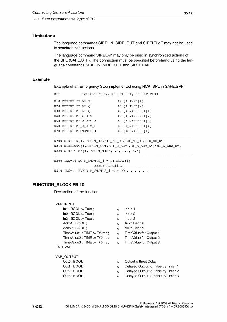
Connecting Sensors/Actuators
7.3 Safe programmable logic (SPL)
05.08
7-242© Siemens AG 2008 All Rights Reserved
SINUMERIK 840D sl/SINAMICS S120 SINUMERIK Safety Integrated (FBSI sl) – 05.2008 Edition
Limitations
The language commands SIRELIN, SIRELOUT and SIRELTIME may not be usedin synchronized actions.
The language command SIRELAY may only be used in synchronized actions ofthe SPL (SAFE.SPF). The connection must be specified beforehand using the lan-guage commands SIRELIN, SIRELOUT and SIRELTIME.
Example
Example of an Emergency Stop implemented using NCK–SPL in SAFE.SPF:
DEF INT RESULT_IN, RESULT_OUT, RESULT_TIME
N10 DEFINE IE_NH_E AS $A_INSE[1]
N20 DEFINE IE_NH_Q AS $A_INSE[2]
N30 DEFINE MI_NH_Q AS $A_MARKERSI[1]
N40 DEFINE MI_C_ABW AS $A_MARKERSI[2]
N50 DEFINE MI_A_ABW_A AS $A_MARKERSI[3]
N60 DEFINE MI_A_ABW_S AS $A_MARKERSI[4]
N70 DEFINE M_STATUS_1 AS $AC_MARKER[1]
;––––––––––––––––––––––––––––––––––––––––––––––––––––––––––––––––––
N200 SIRELIN(1,RESULT_IN,”IE_NH_Q”,”MI_NH_Q”,”IE_NH_E”)
N210 SIRELOUT(1,RESULT_OUT,”MI_C_ABW”,MI_A_ABW_A”,”MI_A_ABW_S”)
N220 SIRELTIME(1,RESULT_TIME,0.4, 2.2, 3.5)
;––––––––––––––––––––––––––––––––––––––––––––––––––––––––––––––––––
N300 IDS=10 DO M_STATUS_1 = SIRELAY(1)
––––––––––––––––––––Error handling–––––––––––––––––––––––––––––
N310 IDS=11 EVERY M_STATUS_1 < > DO . . . . . .
FUNCTION_BLOCK FB 10
Declaration of the function
VAR_INPUTIn1 : BOOL := True ; // Input 1In2 : BOOL := True ; // Input 2In3 : BOOL := True ; // Input 3Ackn1 : BOOL ; // Ackn1 signalAckn2 : BOOL ; // Ackn2 signalTimeValue1 : TIME := T#0ms ; // TimeValue for Output 1TimeValue2 : TIME := T#0ms ; // TimeValue for Output 2TimeValue3 : TIME := T#0ms ; // TimeValue for Output 3
END_VAR
VAR_OUTPUTOut0 : BOOL ; // Output without DelayOut1 : BOOL ; // Delayed Output to False by Timer 1Out2 : BOOL ; // Delayed Output to False by Timer 2Out3 : BOOL ; // Delayed Output to False by Timer 3

Connecting Sensors/Actuators
7.3 Safe programmable logic (SPL)
05.08
7-243© Siemens AG 2008 All Rights ReservedSINUMERIK 840D sl/SINAMICS S120 SINUMERIK Safety Integrated (FBSI sl) – 05.2008 Edition
END_VAR
VAR_INOUTFirstRun: BOOL ; // True by User after 1st start of SPL
END_VAR
The following table shows all formal parameters of the SI relay function:
Signal Type Type Comment
In1 I BOOL Input 1
In2 I BOOL Input 2
In3 I BOOL Input 3
Ackn1 I BOOL Acknowledge input 1
Ackn2 I BOOL Acknowledge input 2
TimeValue1 I TIME Value 1 for switch–off delay
TimeValue2 I TIME Value 2 for switch–off delay
TimeValue3 I TIME Value 3 for switch–off delay
Out0 O BOOL Output, instantaneous (no delay)
Out1 O BOOL Output, delayed by TimeValue1
Out2 O BOOL Output, delayed by TimeValue2
Out3 O BOOL Output, delayed by TimeValue3
FirstRun I/O BOOL Activation of initial state
Parameter FirstRun must be switched to the value TRUE via a retentive data(memory bit, bit in the data block) at the first run–through after the control hasbooted. This data can be preset, e.g., in OB 100. The parameter is reset to FALSEwhen FB 10 is executed for the first time. Separate data must be used for parame-ter FirstRun for each call with separate instance.
Note
The block must be called cyclically by the user program beginning from when thePLC program is started. The user must provide an instance DB with any numberfor this purpose. The call is multi–instance–capable.

Connecting Sensors/Actuators
7.3 Safe programmable logic (SPL)
05.08
7-244© Siemens AG 2008 All Rights Reserved
SINUMERIK 840D sl/SINAMICS S120 SINUMERIK Safety Integrated (FBSI sl) – 05.2008 Edition
7.3.9 System variables for SINUMERIK 840D sl
The following system variables can only be used in combination with SINUMERIKSafety Integrated. They are used when programming the safe programmable logic(SPL).
Also see Chapter 8.4.2 ”Description of the system variables” for a detailed descrip-tion of the system variables.
Table 7-7 Overview of system variables
Systemvariables
Description Value range Data type Possible access for
Partprogram
Synchr.action
r w r w
Actual position
$VA_IS[axis] Safe actual position forSafety Integrated
DOUBLE x x
$AA_IM[axis] Actual position of theclosed–loop control
DOUBLE x x
$VA_IM[axis] Encoder actual value inthe machine coordinatesystem
DOUBLE x x
Error status
$A_XFAULTSI In the crosswise datacomparison betweenNCK and drive of anyaxis, an actual–valueerror has been detected
INT x x
$VA_XFAULTSI[axis name]
The crosswise datacomparison for this axisbetween NCK and drivehas detected an actualvalue error
INT x x
$VA_STOPSI Current Safety Integra-ted stop of the relevantaxis
INT x x
$A_STOPESI Current Safety Integra-ted STOP E for any axis
INT x x
Internal SPL inputs/outputs
$A_INSI[n] NCK input n = 1, 2, ... 64stand for theNo. of the input
BOOL x x
$A_INSID[n] NCK inputs n = 1, 2 INT x x
$A_INSIP[n] Image, PLC input n = 1,2, ...64 BOOL x x
$A_INSIPD[n] Image of the PLC inputs n = 1, 2 INT x x

Connecting Sensors/Actuators
7.3 Safe programmable logic (SPL)
05.08
7-245© Siemens AG 2008 All Rights ReservedSINUMERIK 840D sl/SINAMICS S120 SINUMERIK Safety Integrated (FBSI sl) – 05.2008 Edition
Table 7-7 Overview of system variables
wrwr
$A_OUTSI[n] NCK output n = 1, 2, ... 64stand for theNo. of the out-put
BOOL x x x x
$A_OUTSID[n] NCK outputs n = 1, 2 INT x x x x
$A_OUTSIP[n] Image, PLC output n = 1, 2, ... 64 BOOL x x
$A_OUTSIPD[n] Image of the PLC out-puts
n = 1, 2 INT x x
External SPL inputs/outputs
$A_INSE[n] NCK input n = 1, 2, ... 64stand for theNo. of the input
BOOL x x
$A_INSED[n] NCK inputs n = 1, 2 INT x x
$A_INSEP[n] Image of PLC input n = 1, 2, ... 64stand for theNo. of the input
BOOL x x
$A_INSEPD[n] Image of the PLC inputs n = 1, 2 INT x x
$A_OUTSE[n] NCK output n = 1, 2, ... 64stand for theNo. of the out-put
BOOL x x x x
$A_OUTSED[n] NCK outputs n = 1, 2 INT x x x x
$A_OUTSEP[n] Image of a PLC output n = 1, 2, ... 64stand for theNo. of the out-put
BOOL x x
$A_OUT-SEPD[n]
Image of the PLC out-puts
n = 1, 2 INT x x
SPL markers and timers
$A_MAR-KERSI[n]
Markers n = 1, 2, ... 64stands for theNo. of themarker
BOOL x x x x
$A_MARKER-SID[n]
Markers n = 1, 2 INT x x x x
$A_MARKER-SIP[n]
Image of the PLCmarkers
n = 1,2, ...64 BOOL x x
$A_MARKER-SIPD[n]
Image of the PLCmarkers
n = 1, 2 INT x x
$A_TIMERSI[n] Timer n = 1, 2...16stand for theNo. of the timer
REAL x x x x

Connecting Sensors/Actuators
7.3 Safe programmable logic (SPL)
05.08
7-246© Siemens AG 2008 All Rights Reserved
SINUMERIK 840D sl/SINAMICS S120 SINUMERIK Safety Integrated (FBSI sl) – 05.2008 Edition
Table 7-7 Overview of system variables
wrwr
Miscellaneous
$A_STATSID Crosswise data com-parison error triggered ifthe value is not equal to0
Bits 0...27 cross-wise data com-parison error inthe I/O signals orflag bitsBit 28 crosswisedata comparisonerror ”SPL protec-tion status”Bit 29 timeout inthe communica-tions betweenNCK and SPLBit 30 PLC signalsa stop to the NCK
INT x x
$A_CMDSI 10x change timer valuefor long forced checkingprocedure pulses and/orsingle–channel test stoplogic
Bit 0 = 110x time active
BOOL x x x x
COMM_TO 0 –> 1 communicationstimeout detected, PLCwill go to STOP in 5 s
Bit5 of the 5 stimer wasstarted
BOOL x x
$A_LEVELSID Crosswise data com-parison stack level dis-play: Number of signalsfor which NCK and PLCdetect different signallevels
0...320 INT x x
$A_PLCSIIN Single–channel commu-nication between NCKand PLC SPL
BOOL x x
$A_PLCSIOUT Single–channel commu-nication between NCKand PLC SPL
BOOL x x x x
$AC_SAFE_SYNA_MEM
Free safety synchroniz-ing elements
[0,MAX_INT] x x
Note:r –> read, w –> write
7.3.10 Behavior after power on/mode change/reset
1. After the system has booted, the following Safety Integrated system variablesare assigned the value zero:
$A_INSE(D),$A_OUTSE(D),

Connecting Sensors/Actuators
7.3 Safe programmable logic (SPL)
05.08
7-247© Siemens AG 2008 All Rights ReservedSINUMERIK 840D sl/SINAMICS S120 SINUMERIK Safety Integrated (FBSI sl) – 05.2008 Edition
$A_OUTSI(D),$A_MARKERSI(D),$A_INSEP(D),$A_OUTSEP(D),$A_OUTSIP(D),$A_MARKERSIP(D)$A_INSI(D).
2. Pre–assignment of other variables before cyclic processing of the NCK–SPLstarts can be programmed in the same part program as the NCK–SPL itself. Toensure that the pre–assignment instructions are only performed once, theymust use the following syntax:
IDS=<No.> WHEN TRUE DO<Boot instructions>
As a result of the identifier IDS, the events ”operating mode change” and ”reset”have no effect on the processing of the NCK–SPL.
3. Several boot instructions can be programmed in one block.
7.3.11 SPL data on the PLC side
The safe programmable logic of the PLC (PLC–SPL) is a sub–function of thesafety functions integrated in the SINUMERIK.
Signals
The PLC–SPL signals are in DB18 and are sub–divided into
1. Parameterization part, and
2. Data area/status.
Parameterization part
SPL_READY:The SPL_READY = TRUE signal indicates that the commissioning phase hasbeen completed, i.e. if a crosswise data comparison error has occurred, the basicprogram sends a ”STOP D/E” to all the axes.
STOP_MODE:For crosswise comparison error:0 = external STOP D1 = external STOP Eto the drive

Connecting Sensors/Actuators
7.3 Safe programmable logic (SPL)
05.08
7-248© Siemens AG 2008 All Rights Reserved
SINUMERIK 840D sl/SINAMICS S120 SINUMERIK Safety Integrated (FBSI sl) – 05.2008 Edition
Data area/status
SPL_DATAThe useful (net) data for the PLC–SPL is contained in the SPL_DATA structure.The useful data area is sub–divided into internal inputs/outputs and marker areasand external inputs/outputs that correspond to the hardware I/Os.With the appropriate parameterization for external inputs/outputs, the basic pro-gram transfers the input image of the I/Os to the external inputs in DB 18 and fromthe external outputs in DB 18 to the output.
SPL_DELTAThe SPL_DELTA area is used for diagnostics. A signal with the status TRUE in thisarea means that the signal is different in the NCK and PLC at this bit position.
CMDSISignal CMDSI can be used to extend the timeout value in the crosswise SPL datacomparison by a factor of 10. This extension is used for long forced checking pro-cedure pulses or single–channel test stop logic functions.
STATSIA crosswise data comparison error is indicated in STATSI. STATSI contains thenumber of the signal whose signal difference caused this error. The error number(1–320) refers to SPL_DATA as an array with 5x64=320 signals.
LEVELSIThe signal LEVELSI is used for diagnostics and indicates how many signals withdifferent signal levels are present.
COMM_TOIf communications between the NCK and PLC are interrupted regarding SPLcrosswise data comparison, then after a delay of 5 s the PLC is switched into theSTOP state. Status signal DB18.DBB119, bit 5 is used to inform the SPL program-mer that the 5 s timer was started. This means that it is possible to initiate system–specific actions before the PLC goes into the stop condition.
SPL status signals for SPL_STATUS (DB18.DBB136)For a detailed description, see Chapter 8.3.3 ”PLC data bock (DB 18)”.
INSEP_PROFISAFE (DB18.DBB138)Bit array INSEP_PROFISAFE[1...8] is used to indicate which INSEP bytes areonly assigned to F modules.0 = no PROFIsafe F modules are assigned to INSEP[1...8]1 = PROFIsafe F module is transferred to INSEP[1...8] by the basic program
OUTSEP_PROFISAFE (DB18.DBB140)Bit array OUTSEP_PROFISAFE[1...8] is used to display which OUTSEP bytes areonly assigned F modules.0 = PROFIsafe F modules not assigned to OUTSEP[1...8]1 = OUTSEP[1...8] transferred to PROFIsafe F module using the basic program

Connecting Sensors/Actuators
7.3 Safe programmable logic (SPL)
05.08
7-249© Siemens AG 2008 All Rights ReservedSINUMERIK 840D sl/SINAMICS S120 SINUMERIK Safety Integrated (FBSI sl) – 05.2008 Edition
7.3.12 Direct communications between NCK and PLC–SPL
In SPL applications, a certain degree of single–channel communications betweenthe two SPLs (NCK and PLC) is always required in addition to safety–relatedswitching elements being connected through two channels. Testing external stopsand the Emergency Stop acknowledgment are typical applications.
In order to be able to exchange single–channel SI–specific signals between theNCK and PLC in a dedicated data area, a corresponding communication interfaceexists between these components. The meaning of the individual bits in this inter-face are defined by the user.
NCK PLC
$A_PLCSIOUT[1...32] DB18.DBD128 32 bits from the NCK to PLC
$A_PLCSIIN[1...32] DB18.DBD132 32 bits from the PLC to NCK
Limitations
System variables $A_PLCSIOUT[1...32] and $A_PLCSIIN[1...32] are protected sothat they cannot be accessed from other programs, except the NCK–SPL program(SAFE.SPF). A corresponding programming command is rejected with the alarm17070 ”Channel %1 block %2 Data write–protected”.

Connecting Sensors/Actuators
7.4 Safe brake test (SBT)
05.08
7-250© Siemens AG 2008 All Rights Reserved
SINUMERIK 840D sl/SINAMICS S120 SINUMERIK Safety Integrated (FBSI sl) – 05.2008 Edition
7.4 Safe brake test (SBT)
7.4.1 Field of application
When the drives are powered–down axes and mechanical systems can drop as aresult of gravity. The mechanical braking system test should be used for all axeswhich must be prevented from moving in an uncontrolled manner by a holdingbrake. This test function is primarily intended for so–called ”vertical axes”.
The functionality is based on ”travel to fixed stop”. The travel to fixed stop can beindividually parameterized to test the function of the mechanical braking system. Itis activated and deselected from the PLC. For further details on travel to fixedstop, see /FB1/, F1.
The machine manufacturer can use his PLC user program to close the brake at asuitable instant in time (nominal value, every 8h similar to the SI test stop) and initi-ates the drive to produce an additional force in addition to the weight of the axis. Ina fault–free state, the brake can apply the necessary force, i.e. the axis will hardlymove.When an error occurs, the actual position value exits the parameterizable monitor-ing window. In this case, travel to fixed stop is terminated so that the position con-troller can prevent the axis falling. The brake test is then negatively acknowledged.
The brake test must always be started when the axis is at a standstill (also seeChapter 7.4.5 ”Activation”). The direction in which the drive produces its force isspecified by the PLC using a ”traversing motion” via FC 18. The target of this tra-versing motion must be able to be reached without incurring any potential hazardfor the case that the brake cannot provide the necessary force.
7.4.2 Parameter assignment
The user can use the following axial NCK machine data to parameterize the func-tion test of the mechanical braking system:
for 840D slMD 37000: $MA_FIXED_STOP_MODEMD 37030: $MA_FIXED_STOP_THRESHOLDMD 36966 $MA_SAFE_BRAKETEST_TORQUEMD 36967: $MA_SAFE_BRAKETEST_POS_TOLMD 36968: $MA_SAFE_BRAKETEST_CONTROL

Connecting Sensors/Actuators
7.4 Safe brake test (SBT)
05.08
7-251© Siemens AG 2008 All Rights ReservedSINUMERIK 840D sl/SINAMICS S120 SINUMERIK Safety Integrated (FBSI sl) – 05.2008 Edition
$MA_FIXED_STOP_MODE
The function test of the mechanical braking system is enabled by setting bit 1 in$MA_FIXED_STOP_MODE. If the user needs to travel to a fixed stop with thisaxis from the part program, bit 0 can also be set. It is internally monitored to checkthat only one type of travel to fixed stop is active at a time. In the case of an error,Alarm 20092, ”Axis % Travel to fixed stop still active” is issued.
$MA_SAFE_BRAKETEST_TORQUE
The machine manufacturer must parameterize the total required brake holdingtorque in the axial MD $MA_SAFE_BRAKETEST_TORQUE. Internally, this is usedto calculate the drive torque that is required in addition to the weight of the axis toload the brake.For SINAMICS S120 the drive torque is determined when the function test is se-lected. It is thus possible to take into account any deviation from the torque due toweight parameterized in drive parameter p1532 (or force due to weight). This en-sures that the brake test can also be carried out with varying machine loads (e.g.different workpieces or tools). The drive torque to load the holding brake is limitedto the maximum motor torque if the desired braking torque would require a higherdrive torque.If the load torque at an axis changes so significantly that a sensible value cannot beparameterized in drive parameter p1532, then the automatic determination of the loadtorque available must be activated using $MA_SAFE_BRAKETEST_CONTROL.Value for MD36966 = (test torque of brake / p2003) * 100The value from $MA_SAFE_BRAKETEST_TORQUE refers to the referencetorque or the reference force from drive parameter p2003, whose image is saved in$MA_SAFE_BRAKETEST_TORQUE_NORM.

Connecting Sensors/Actuators
7.4 Safe brake test (SBT)
05.08
7-252© Siemens AG 2008 All Rights Reserved
SINUMERIK 840D sl/SINAMICS S120 SINUMERIK Safety Integrated (FBSI sl) – 05.2008 Edition
m
t0
Upper torque limiting + mFXS
Lower torque limiting – mFXS
3
3
2
1
Torque limiting+ mFXS
Torque limiting– mFXS
Torque limiting
MD 36966
2
mFXS
mFXS
mDrive
mDrive
mActp1532
Fig. 7-24 Torque limiting for SINAMICS S120
1
When selecting the brake test, the holding torque required for the force due to theweight of the axis is internally measured (mAct).
2
The drive must only additionally provide the difference between this torque and thebraking torque from MD 36966 $MA_SAFE_BRAKETEST_TORQUE. In the dia-gram 7-24, this torque is designated with mDrive.
3
The torque limiting of SINAMICS is symmetrical around the torque from drive pa-rameter p1532. In the diagram 7-24 the measured torque m_Act is however lessthan p1532.This is the reason that mFXS from Fig. 7-24 is entered as torque limiting.mFXS is the sum from mdrive and the drive parameter p1532. If the measuredtorque mact matches that parameterized in drive parameter p1532, mFXS becomesthe value from the MD $MA_SAFE_BRAKETEST_TORQUE.
Incorrect parameterization in MD $MA_SAFE_BRAKETEST_TORQUE or driveparameter p1532 could mean that the drive with reduced torque cannot even apply
Connecting Sensors/Actuators
7.4 Safe brake test (SBT)
05.08
7-253© Siemens AG 2008 All Rights ReservedSINUMERIK 840D sl/SINAMICS S120 SINUMERIK Safety Integrated (FBSI sl) – 05.2008 Edition
the required holding torque. This parameterization is detected when the brake testis selected and results in Alarm 20095 (see Chapter 10.2). The fact that the actualtorque/force setpoint is displayed in parameter r1509 makes it easier to correctlyparameterize drive parameter p1532. If only the force due to the weight is effec-tive, then this value can be directly transferred into the drive parameter. This valuemust be entered – with an additional safety margin – into MD $MA_SAFE_BRAKE-TEST_TORQUE. The magnitude of the safety margin is orientated to the maxi-mum holding force of the brake to be tested.
$MA_SAFE_BRAKETEST_CONTROL
Some machines have braked axes whose load torque can very significantly overthe complete traversing range or depending on the workpiece or tool being used. Ifdrive parameter p1532 cannot be generally parameterized for all of the situations,an automatic determination of the load torque present at the start of the brakingtest can be activated using MD 36968 $MA_SAFE_BRAKETEST_CONTROL. If bit0 of $MA_SAFE_BRAKETEST_CONTROL is set to 1, then the torque, determinedat the start of the brake test (mAct from Fig. 7-24 or Fig. 7-25) is temporarily usedas average value for the torque limiting in the drive.
The user must carefully ensure that the brake is not previously closed thus pre-venting an incorrect load torque being determined. This would then mean that thebrake test would be carried out with an incorrect torque. The plausibility of the loadtorque is then no longer checked.This is the reason that this should only be activated if it is not possible to sensiblyparameterize parameter 1532.
$MA_SAFE_BRAKETEST_POS_TOL
The monitoring window for the maximum permissible movement during the braketest is defined in the axial MD $MA_SAFE_BRAKETEST_POS_TOL. The PLCactively monitors this position window – from the start of the brake test and notonly when it has been detected that the fixed stop has been reached. This is a dif-ference when compared to activating the traversing to the fixed stop function fromthe part program.
$MA_FIXED_STOP_THRESHOLD
The contour deviation that is determined is always used in the brake test to detectthat the fixed stop has been reached. The parameterization in$MA_FIXED_STOP_BY_SENSOR is therefore irrelevant. The required thresholdvalue must be set in MD $MA_FIXED_STOP_THRESHOLD. This means that thetraversing distance from the PLC via FC 18 must be greater than this thresholdvalue. Furthermore, the drive must have reached its torque limit parameterizedusing $MA_SAFE_BRAKETEST_TORQUE.

Connecting Sensors/Actuators
7.4 Safe brake test (SBT)
05.08
7-254© Siemens AG 2008 All Rights Reserved
SINUMERIK 840D sl/SINAMICS S120 SINUMERIK Safety Integrated (FBSI sl) – 05.2008 Edition
Torque limits
The torque limits p1520[0] and p1521[0] and the reference torque p2003 are pre–assigned when commissioning the motor. The torque limits and the referencetorque are pre–assigned differently depending on the technological applicationp0500 and dependent on the hardware components being used.
Further, the torque limits p1522[0] and p1523[0] are pre–assigned as follows:p1522[0] 63:2902:5 reference to +100% referred to p2003 in the same MotorModulep1523[0] 63:2902:12 reference to –100% referred to p2003 in the same MotorModule
When using the safe brake test, these pre–assignments for p1522[0]/p1523[0] maynot be changed.However, when upgrading the software, the following setting, which is also permissible,can be present:p1522[0] 0:1.0 100% of p2003p1523[0] 63:2900.0 reference to p2900 in the same Motor Modulep2900[0] –100% –100% from p2003
To ensure that the brake test functions without any errors, it should be checked as towhether the required test torque in MD 36966 $MA_SAFE_BRAKETEST_TORQUE is notprevented from being generated due to the fact that torque limits are effective in the drive.For details on this, please see SINAMICS List Manual, e.g. function charts 5610 and 5620.For instance, the selectable torque limits from p1520/p1521 and p1522/p1523 maynot be set so low that the required torque cannot be established for the brake test.When required, p1520/p1521 or p2003 should be adapted. When making a changeto p2003, machine data 36966 should be re–determined.Further, e.g. the following parameters can also have a limiting effect:p1530/p1531 (power limit, motoring/regenerating)p0640 (current limit)p0326 (stall torque correction factor)
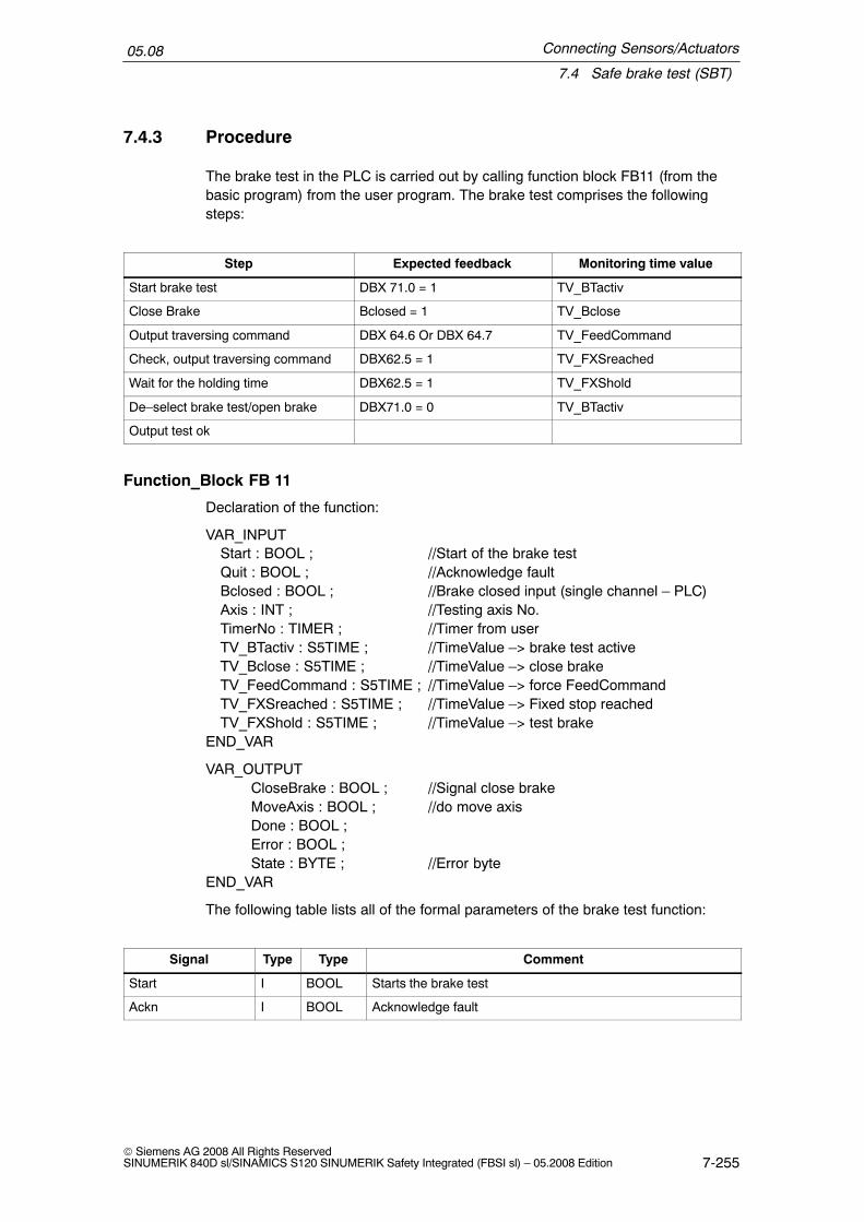
Connecting Sensors/Actuators
7.4 Safe brake test (SBT)
05.08
7-255© Siemens AG 2008 All Rights ReservedSINUMERIK 840D sl/SINAMICS S120 SINUMERIK Safety Integrated (FBSI sl) – 05.2008 Edition
7.4.3 Procedure
The brake test in the PLC is carried out by calling function block FB11 (from thebasic program) from the user program. The brake test comprises the followingsteps:
Step Expected feedback Monitoring time value
Start brake test DBX 71.0 = 1 TV_BTactiv
Close Brake Bclosed = 1 TV_Bclose
Output traversing command DBX 64.6 Or DBX 64.7 TV_FeedCommand
Check, output traversing command DBX62.5 = 1 TV_FXSreached
Wait for the holding time DBX62.5 = 1 TV_FXShold
De–select brake test/open brake DBX71.0 = 0 TV_BTactiv
Output test ok
Function_Block FB 11
Declaration of the function:
VAR_INPUTStart : BOOL ; //Start of the brake testQuit : BOOL ; //Acknowledge faultBclosed : BOOL ; //Brake closed input (single channel – PLC)Axis : INT ; //Testing axis No.TimerNo : TIMER ; //Timer from userTV_BTactiv : S5TIME ; //TimeValue –> brake test activeTV_Bclose : S5TIME ; //TimeValue –> close brakeTV_FeedCommand : S5TIME ; //TimeValue –> force FeedCommandTV_FXSreached : S5TIME ; //TimeValue –> Fixed stop reachedTV_FXShold : S5TIME ; //TimeValue –> test brake
END_VAR
VAR_OUTPUTCloseBrake : BOOL ; //Signal close brakeMoveAxis : BOOL ; //do move axisDone : BOOL ;Error : BOOL ;State : BYTE ; //Error byte
END_VAR
The following table lists all of the formal parameters of the brake test function:
Signal Type Type Comment
Start I BOOL Starts the brake test
Ackn I BOOL Acknowledge fault

Connecting Sensors/Actuators
7.4 Safe brake test (SBT)
05.08
7-256© Siemens AG 2008 All Rights Reserved
SINUMERIK 840D sl/SINAMICS S120 SINUMERIK Safety Integrated (FBSI sl) – 05.2008 Edition
Signal CommentTypeType
Bclosed I BOOL Feedback input whether a control signal has been issued toclose the brake (single–channel PLC)
Axis I INT Axis number of axis to be tested
TimerNo I TIMER Timer from user program
TV_Btactiv I S5TIME Monitoring time value –> brake test active. Check the axis sig-nal DBX71.0
TV_Bclose I S5TIME Monitoring time value –> close brake. Check the input signalBclosed after the CloseBrake output was set.
TV_FeedCommand I S5TIME Monitoring time value –> output traversing command. Checktraversing commands after MoveAxis has been set.
TV_FXSreached I S5TIME Monitoring time value –> fixed stop reached
TV_FXShold I S5TIME Monitoring time value –> test brake
CloseBrake O BOOL Request, close brake
MoveAxis O BOOL Request, initiate traversing motion
Done O BOOL Test successfully completed
Error O BOOL Error has occurred
State O BYTE ErrorStatus
Fault IDs
State Description
0 No error
1 Start conditions not fulfilled, e.g., the axis is not in closed–loop control/brakeclosed/axis inhibited
2 No NC checkback in ”Brake test active” signal on selection of brake test
3 No ”Brake applied” checkback by input signal Bclosed
4 No traversing command output (e.g. axis motion has not been started)
5 Fixed stop is not reached –> axis RESET was initiated
6 Traversing inhibit/approach too slow –> fixed stop cannot be reached. Monitoringtime TV_FXSreached has expired.
7 Brake is not holding at all (the end position is reached)/approach speed is too high
8 Brake opens during the holding time
9 Error when deselecting the brake test
10 Internal error
11 ”PLC–controlled axis” signal not enabled in the user program

Connecting Sensors/Actuators
7.4 Safe brake test (SBT)
05.08
7-257© Siemens AG 2008 All Rights ReservedSINUMERIK 840D sl/SINAMICS S120 SINUMERIK Safety Integrated (FBSI sl) – 05.2008 Edition
Note
The block must be called by the user program. The user must provide an instanceDB with any number for this purpose. The call is multi–instance–capable.
Example of calling FB11UN M 111.1 //Request close Z axis brake from FB= DB33.DBX23.5; //Control Z axis brakeUN DB33.DBX92.5 = M111.5 //Z axis brake is closed
AUF ”Axis3”; //Brake test, Z axis
O E 73.0; //Initiates the brake test, Z axisO M 110.7; //Brake test runningFP M 110.0;UN M 111.4; //Fault has occurredS M 110.7; //Brake test runningS M 110.6; //Next stepSPBN m001;L DBB 68;UW W#16#F;T MB 115; //Note channel statusL B#16#10;T DBB 8; //Request neutral axis
m001: U DBX 68.6; //Feedback signal, axis is neutralU M 110.6;FP M 110.1;R M 110.6;S M 110.5; //Next stepS DBX 28.7; //Request PLC–monitored axis
U DBX 63.1; //Feedback signal, the PLC is monitoring the axisU M 110.5;FP M 110.2;R M 110.5;S M 111.0; //Start the brake test for FB
CALL FB 11 , DB211 (//Brake test moduleStart := M111.0, //Start brake testQuit := E3.7, //Acknowledge error with Reset keyBclosed :=M111.5, //Feedback signal close brake initiatedAxis :=3 //Axis number of axis to be tested, Z axisTimerNo :=T 110 //Timer numberTV_BTactiv :=S5T#200MS, //Monitoring time value: Brake test active
DBX71.0TV_Bclosed :=S5T#1S, //Monitoring time value: Brake closed

Connecting Sensors/Actuators
7.4 Safe brake test (SBT)
05.08
7-258© Siemens AG 2008 All Rights Reserved
SINUMERIK 840D sl/SINAMICS S120 SINUMERIK Safety Integrated (FBSI sl) – 05.2008 Edition
TV_FeedCommand :=S5T#1S, //Monitoring time value: Travel commandare outputTV_FXSreached := S5T#1S, //Monitoring time value: Fixed stop reachedTV_FXShold := S5T#2S, //Monitoring time value: Brake test timeCloseBrake := M111.1, //Request, close brakeMoveAxis := M111.2, //Request, initiate traversing motionDone := M111.3, //Test successfully completedError := M111.4, //Error occurredState := MB112); //Error status
AUF ”Axis3”; //Brake test, Z axis
U M 111.2; //Move axisFP M 111.5; //FC18 startS M 111.7; //Start FC18O M 111.3; //Test successfully completedO M 111.4; //Fault has occurredFP M 110.3;R DBX 28.7; //Request, PLC monitored axis
UN DBX 63.1; //Feedback signal, the PLC is monitoring the axisU M 111.0; //Start the brake test for FBU M 110.7; //Brake test runningFP M 110.4;R M 111.0 //Start the brake test for FBR M 110.7; //Brake test runningSPBN m002;L MB 115; //Load noted channel stateOW W#16#10;T DBB 8; //Request channel axis
m002: NOP 0;
CALL ”SpinCtrl” (//Traverse Z axisStart :=M 111.7, //Start of traversing motionStop :=FALSEFunct := B#16#5, //Mode: Axis modeMode := B#16#1, //Traverse: IncrementalAxisNo := 3, //Axis number of the axis to be traversed, Z–axisPos := –5.000000e+000, // Distance travelled: Minus 5 mmFRate := 1.000000e+003, //Feed rate: 1000 mm/minInPos := M 113.0, //Position reachedError := M 113.1, //Fault has occurredState := MB 114); //Error status
AUF ”Axis3”; Brake text, Z axisU M 113.0; //Position reachedO M 113.1; //Fault has occurredFP M 113.2;R M 111.7 //Start FC18

Connecting Sensors/Actuators
7.4 Safe brake test (SBT)
05.08
7-259© Siemens AG 2008 All Rights ReservedSINUMERIK 840D sl/SINAMICS S120 SINUMERIK Safety Integrated (FBSI sl) – 05.2008 Edition
7.4.4 Limitations
During the brake test, traversing to fixed stop and/or traverse with limited torqueFOC may not be active at the same time. In this case, Alarm 20092, ”Axis %1travel to fixed stop still active” is triggered.
The axis should be transferred back from the PLC after the brake test has beencompleted.
During the brake test, contour monitoring is not active. After the PLC has startedtraversing motion then there is also no standstill monitoring.
The function test/check of the brake mechanical system cannot be used for gantryaxes.
If the parameterization of parameter p1532 (> 5%) deviates from the measuredtorque at the start of the brake test – then the brake test must be carried out in thesame direction in which the load torque is effective. In the case of an error – Alarm20097 ”Axis %1 incorrect brake test direction” is output.
7.4.5 Activating
The brake test must always be started when the axis is at a standstill. For the en-tire duration of the brake test, the enable signals of the parameterized axis must beset to enable (e.g. the controller inhibit, feed enable signals). The signal ”PLC–con-trolled axis” (DB ”Axis”.DBX28.7) must still be set to 1 by the user program for theentire duration of the test. Prior to activating the signal ”PLC controlled axis”, theaxis must be set as ”neutral axis”, e.g. set byte 8 in the axis DB to channel 0. Setthe activating signal in the same byte. The block may not be started until the NCfeedback signal has been received via the appropriate bit (DB ”Axis”.DBX63.1).For a PLC–monitored axis, also see:
References: /FB2/ P2 ”Autonomous single–axis processes”
!Warning
The brake test must be carried out before carrying out the test stop. If the braketest was not successful (i.e. the brake cannot hold the axis), then it is notpermissible that the test stop is carried out. Users must carefully take this intoconsideration when configuring the brake test and test stop. The brake may onlybe tested when the axis is in an absolutely safe position.

Connecting Sensors/Actuators
7.4 Safe brake test (SBT)
05.08
7-260© Siemens AG 2008 All Rights Reserved
SINUMERIK 840D sl/SINAMICS S120 SINUMERIK Safety Integrated (FBSI sl) – 05.2008 Edition
7.4.6 Example
An example of incorrect parameterization that results in Alarm 20095, ”Axis %1impermissible holding torque, measured torque %2” is shown in the following dia-gram: The torque due to weight in drive parameter p1532 has been parameterizedconsiderably lower than the measured torque mAct. The calculated torque limitmFXS, positioned symmetrically around this MD, would mean that the drive wouldnot be able to produce the required holding torque for this axis (p1532+mFXS islower than mAct).
m
t0
Lower torque limiting – mFXS
Upper torque limiting + mFXS
p1532
MD 36966
mAct mDrive
mDrive
mFXS
mFXS
1 2
2
3
3
Fig. 7-25 Example of incorrect parameterization
If parameter p1532 cannot be sensibly parameterized for all situations where thebrake test is to be carried out, then the automatic determination of the load torquemust be activated using MA_SAFE_BRAKETEST_CONTROL.
Commissioning
To support the commissioning of the brake test Alarm 20096, ”Axis %1 brake testaborted, additional info %2” can be enabled using bit 5 in machine data$MN_ENABLE_ALARM_MASK. This alarm supplies detailed information if thebrake test is interrupted.

8-261© Siemens AG 2008 All Rights ReservedSINUMERIK 840D sl/SINAMICS S120 SINUMERIK Safety Integrated (FBSI sl) – 05.2008 Edition
Data Description
8.1 Machine data for SINUMERIK 840D sl
8.1.1 Overview of the machine data
Note
The meaning of the symbols used in the table is as follows:
� This data is calculated into SAFE_ACT_CHECKSUM[0].
� This data is calculated into SAFE_ACT_CHECKSUM[1].
–– This data is not calculated into any checksum.
Table 8-1 Overview of machine data for SINUMERIK 840D sl
Number Name Name Checksums MD
General ($MN_ ... )
10050 SYSCLOCK_CYCLE_TIME Basic system clock cycle, see /FB1/, G2 �
10060 POSCTRL_SYSCLOCK_TIME_RATIO Factor, position controller clock cycle, see/FB1/, G2
––
10070 IPO_SYSCLOCK_CYCLE_TIME_RATIO Factor, interpolator clock cycle �
10090 SAFETY_SYSCLOCK_TIME_RATIO Factor for the monitoring clock cycle ––
10091 INFO_SAFETY_CYCLE_TIME Display, monitoring clock cycle time ––
10092 INFO_CROSSCHECK_CYCLE_TIME Displays the clock cycle time for a cross-wise data comparison
––
10093 INFO_NUM_SAFE_FILE_ACCESS Number of SPL file access operations ––
10094 SAFE_ALARM_SUPPRESS_LEVEL Alarm suppression level ––
10096 SAFE_DIAGNOSIS_MASK Safety Integrated diagnostic functions ––
10097 SAFE_SPL_STOP_MODE Stop response for SPL errors �
10098 PROFISAFE_IPO_TIME_RATIO Factor PROFIsafe communications clockcycle time
�
10099 INFO_PROFISAFE_CYCLE_TIME PROFIsafe communications clock cycletime
––
10200 INT_INCR_PER_MM Computational resolution for linear positionssee /FB1/, G2
––
8

Data Description
8.1 Machine data for SINUMERIK 840D sl
05.08
8-262© Siemens AG 2008 All Rights Reserved
SINUMERIK 840D sl/SINAMICS S120 SINUMERIK Safety Integrated (FBSI sl) – 05.2008 Edition
Table 8-1 Overview of machine data for SINUMERIK 840D sl
Checksums MDNameNameNumber
10210 INT_INCR_PER_DEG Computational resolution for angular posi-tions see /FB1/, G2
––
10385 PROFISAFE_MASTER_ADRESS PROFIsafe address of the PROFIsafemaster module
�
10386 PROFISAFE_IN_ADRESS PROFIsafe address of an input module �
10387 PROFISAFE_OUT_ADRESS PROFIsafe address of a PROFIsafe outputmodule
�
10388 PROFISAFE_IN_ASSIGN Input assignment, $A_INSE to PROFIsafeinput module
�
10389 PROFISAFE_OUT_ASSIGN Output assignment, $A_OUTSE to PROFI-safe module
�
10393 SAFE_DRIVE_LOGIC_ADDRESS Logical drive addresses, SI �
13300 PROFISAFE_IN_FILTER F useful (net) data filter IN �
13301 PROFISAFE_OUT_FILTER F net (useful) data filter OUT �
13310 SAFE_SPL_START_TIMEOUT Delay, display Alarm 27097 ––
Channel-specific ($MC_ ... )
20108 PROG_EVENT_MASK Event–controlled program call ––
28251 MM_NUM_SAFE_SYNC_ELEMENTS Number of elements for expressions insafety synchronized actions
––
Axis/spindle-specific ($MA_ ... )
30240 ENC_TYPE Encoder type of the actual value sensing(position actual value) see /FB1/, G2
––
30300 IS_ROT_AX Rotary axis/spindle see /FB1/, R2 ––
30320 DISPLAY_IS_MODULO Modulo 360 degrees display for rotary axisor spindle see /FB1/, R2
––
30330 MODULO_RANGE Size of the modulo range see /FB1/, R2 ––
32300 MA_AX_ACCEL Axis acceleration see /FB1/, B2 ––
35200 GEAR_STEP_SPEEDCTRL_ACCEL Acceleration in the open–loop speed con-trolled mode see /FB1/, S1
––
35210 GEAR_STEP_POSCTRL_ACCEL Acceleration in the closed–loop positioncontrolled mode see /FB1/, S1
––
35410 SPIND_OSCILL_ACCEL Acceleration when oscillating see /FB1/, S1 ––
36060 STANDSTILL_VELO_TOL Threshold velocity/speed ”axis/spindle sta-tionary” see /FB1/, A2
––
36620 SERVO_DISABLE_DELAY_TIME Shutdown delay controller enable see /FB1/,A2
––
36901 SAFE_FUNCTION_ENABLE Enable safety–related functions �
36902 SAFE_IS_ROT_AX Rotary axis �
36903 SAFE_CAM_ENABLE Enable safe cam track �
36905 SAFE_MODULO_RANGE Modulo value, safe cams �
36906 SAFE_CTRLOUT_MODULE_NR SI drive assignment �

Data Description
8.1 Machine data for SINUMERIK 840D sl
05.08
8-263© Siemens AG 2008 All Rights ReservedSINUMERIK 840D sl/SINAMICS S120 SINUMERIK Safety Integrated (FBSI sl) – 05.2008 Edition
Table 8-1 Overview of machine data for SINUMERIK 840D sl
Checksums MDNameNameNumber
36907 SAFE_DRIVE_PS_ADDRESS PROFIsafe address of the drive �
36912 SAFE_ENC_INPUT_NR Actual value assignment: Drive encodernumber
�
36914 SAFE_SINGLE_ENC SI single–encoder system �
36916 SAFE_ENC_IS_LINEAR Linear scale �
36917 SAFE_ENC_GRID_POINT_DIST Grid spacing, linear scale �
36918 SAFE_ENC_RESOL Encoder pulses per revolution �
36919 SAFE_ENC_PULSE_SHIFT Shift factor of the encoder multiplication �
36920 SAFE_ENC_GEAR_PITCH Leadscrew pitch �
36921 SAFE_ENC_GEAR_DENOM[n] Denominator, gearbox ratio encoder/load �
36922 SAFE_ENC_GEAR_NUMERA[n] Numerator, gearbox ratio encoder/load �
36923 SAFE_INFO_ENC_RESOL Safety–related encoder resolution ––
36925 SAFE_ENC_POLARITY Direction reversal actual value �
36927 SAFE_ENC_MOD_TYPE Encoder evaluation type �
36928 SAFE_ENC_IDENT Encoder identification �
36930 SAFE_STANDSTILL_TOL Zero speed tolerance �
36931 SAFE_VELO_LIMIT[n] Limit value for safely reduced speed �
36932 SAFE_VELO_OVR_FACTOR[n] SG selection values �
36933 SAFE_DES_VELO_LIMIT SG setpoint speed limiting ––
36934 SAFE_POS_LIMIT_PLUS[n] Upper limit value for safe limit position �
36935 SAFE_POS_LIMIT_MINUS[n]] Lower limit value for safe limit position �
36936 SAFE_CAM_POS_PLUS[n] Plus cam position for safe cams �
36937 SAFE_CAM_POS_MINUS[n] Minus cam position for safe cams �
36938 SAFE_CAM_TRACK_ASSIGN[n] Cam track assignment �
36940 SAFE_CAM_TOL Tolerance for safe cams �
36942 SAFE_POS_TOL Tolerance, actual value comparison (cross-wise)
�
36944 SAFE_REFP_POS_TOL Tolerance, actual value comparison (refer-encing)
�
36946 SAFE_VELO_X Speed limit nx �
36948 SAFE_STOP_VELO_TOL Speed tolerance for safe acceleration moni-toring
�
36949 SAFE_SLIP_VELO_TOL Speed tolerance, slip �
36950 SAFE_MODE_SWITCH_TIME Tolerance time for SGE changeover �
36951 SAFE_VELO_SWITCH_DELAY Delay time, speed changeover �
36952 SAFE_STOP_SWITCH_TIME_C Transition time, STOP C to safe Standstill �
36953 SAFE_STOP_SWITCH_TIME_D Transition time, STOP D to safe Standstill �
36954 SAFE_STOP_SWITCH_TIME_E Transition time, STOP E to safe Standstill �
36955 SAFE_STOP_SWITCH_TIME_F Transition time STOP F to STOP B �

Data Description
8.1 Machine data for SINUMERIK 840D sl
05.08
8-264© Siemens AG 2008 All Rights Reserved
SINUMERIK 840D sl/SINAMICS S120 SINUMERIK Safety Integrated (FBSI sl) – 05.2008 Edition
Table 8-1 Overview of machine data for SINUMERIK 840D sl
Checksums MDNameNameNumber
36956 SAFE_PULSE_DISABLE_DELAY Delay time, pulse cancellation �
36957 SAFE_PULSE_DIS_CHECK_TIME Time to check pulse cancellation �
36958 SAFE_ACCEPTANCE_TST_TIMEOUT Time limit for the acceptance test duration �
36960 SAFE_STANDSTILL_VELO_TOL Shutoff speed for pulse suppression �
36961 SAFE_VELO_STOP_MODE Stop response, safely reduced speed �
36962 SAFE_POS_STOP_MODE Stop response, safe limit position �
36963 SAFE_VELO_STOP_REACTION[n] Stop response, safely reduced speed �
36964 SAFE_IPO_STOP_GROUP Grouping, safety IPO response ––
36965 SAFE_PARK_ALARM_SUPPRESS Alarm suppression for parking axes �
36966 SAFE_BRAKETEST_TORQUE Holding torque, brake test �
36967 SAFE_BRAKETEST_POS_TOL Position tolerance, brake test �
36968 SAFE_BRAKETEST_CONTROL Sequence check for the brake test �
36969 SAFE_BRAKETEST_TORQUE_NORM Reference quantity for the holding torque,brake test
�
36970 SAFE_SVSS_DISABLE_INPUT Input assignment, SBH/SG deselection �
36971 SAFE_SS_DISABLE_INPUT Input assignment, SBH deselection �
36972 SAFE_VELO_SELECT_INPUT[n] Input assignment, SG selection �
36973 SAFE_POS_SELECT_INPUT Input assignment, SE selection �
36974 SAFE_GEAR_SELECT_INPUT[n] Input assignment, gearbox ratio selection �
36977 SAFE_EXT_STOP_INPUT[n] Input assignment, external brake request �
36978 SAFE_OVR_INPUT[n] Input assignment, SG override �
36980 SAFE_SVSS_STATUS_OUTPUT Output assignment, SBH/SG active �
36981 SAFE_SS_STATUS_OUTPUT Output assignment for SBH active �
36982 SAFE_VELO_STATUS_OUTPUT[n] Output assignment active SG selection �
36985 SAFE_VELO_X_STATUS_OUTPUT Output assignment for n < nx �
36987 SAFE_REFP_STATUS_OUTPUT Output assignment, axis safely referenced �
36988 SAFE_CAM_PLUS_OUTPUT[n] Output assignment, SN1+ to SN4+ �
36989 SAFE_CAM_MINUS_OUTPUT[n] Output assignment, SN1– to SN4– �
36990 SAFE_ACT_STOP_OUTPUT[n] Output assignment, active STOP �
36992 SAFE_CROSSCHECK_CYCLE Displays the axial crosswise comparisonclock cycle
––
36993 SAFE_CONFIG_CHANGE_DATE[n] Date/time of the last change SI–NCK–MD ––
36994 SAFE_PREV_CONFIG[n] Data, previous safety function ––
36995 SAFE_STANDSTILL_POS Standstill position ––
36997 SAFE_ACKN User acknowledgement ––
36998 SAFE_ACT_CHECKSUM Actual checksum ––
36999 SAFE_DES_CHECKSUM Reference checksum ––
37000 FIXED_STOP_MODE Travel to fixed stop mode ––
37900 SAFE_CAM_TRACK_OUTPUT Output assignment cam tracks 1 to 4 �

Data Description
8.1 Machine data for SINUMERIK 840D sl
05.08
8-265© Siemens AG 2008 All Rights ReservedSINUMERIK 840D sl/SINAMICS S120 SINUMERIK Safety Integrated (FBSI sl) – 05.2008 Edition
Table 8-1 Overview of machine data for SINUMERIK 840D sl
Checksums MDNameNameNumber
37901 SAFE_CAM_RANGE_OUTPUT_1 Output assignment, cam range for camtrack 1
�
37902 SAFE_CAM_RANGE_OUTPUT_2 Output assignment, cam range for camtrack 2
�
37903 SAFE_CAM_RANGE_OUTPUT_3 Output assignment, cam range for camtrack 3
�
37904 SAFE_CAM_RANGE_OUTPUT_4 Output assignment, cam range for camtrack 4
�
37906 SAFE_CAM_RANGE_BIN_OUTPUT_1 Output assignment, cam range bit for camtrack 1
�
37907 SAFE_CAM_RANGE_BIN_OUTPUT_2 Output assignment, cam range bit for camtrack 2
�
37908 SAFE_CAM_RANGE_BIN_OUTPUT_3 Output assignment, cam range bit for camtrack 3
�
37909 SAFE_CAM_RANGE_BIN_OUTPUT_4 Output assignment, cam range bit for camtrack 4
�
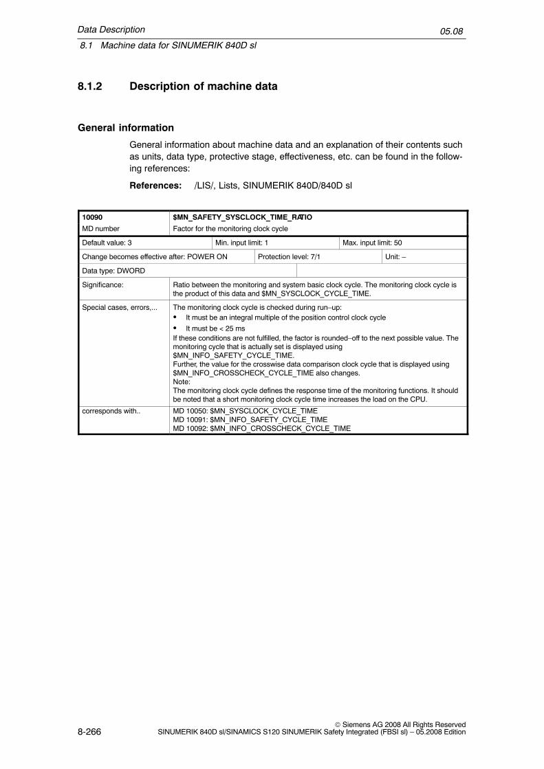
Data Description
8.1 Machine data for SINUMERIK 840D sl
05.08
8-266© Siemens AG 2008 All Rights Reserved
SINUMERIK 840D sl/SINAMICS S120 SINUMERIK Safety Integrated (FBSI sl) – 05.2008 Edition
8.1.2 Description of machine data
General information
General information about machine data and an explanation of their contents suchas units, data type, protective stage, effectiveness, etc. can be found in the follow-ing references:
References: /LIS/, Lists, SINUMERIK 840D/840D sl
10090 $MN_SAFETY_SYSCLOCK_TIME_RATIO
MD number Factor for the monitoring clock cycle
Default value: 3 Min. input limit: 1 Max. input limit: 50
Change becomes effective after: POWER ON Protection level: 7/1 Unit: –
Data type: DWORD
Significance: Ratio between the monitoring and system basic clock cycle. The monitoring clock cycle isthe product of this data and $MN_SYSCLOCK_CYCLE_TIME.
Special cases, errors,... The monitoring clock cycle is checked during run–up:� It must be an integral multiple of the position control clock cycle
� It must be < 25 ms If these conditions are not fulfilled, the factor is rounded–off to the next possible value. Themonitoring cycle that is actually set is displayed using$MN_INFO_SAFETY_CYCLE_TIME.Further, the value for the crosswise data comparison clock cycle that is displayed using$MN_INFO_CROSSCHECK_CYCLE_TIME also changes.Note:The monitoring clock cycle defines the response time of the monitoring functions. It shouldbe noted that a short monitoring clock cycle time increases the load on the CPU.
corresponds with.. MD 10050: $MN_SYSCLOCK_CYCLE_TIMEMD 10091: $MN_INFO_SAFETY_CYCLE_TIMEMD 10092: $MN_INFO_CROSSCHECK_CYCLE_TIME

Data Description
8.1 Machine data for SINUMERIK 840D sl
05.08
8-267© Siemens AG 2008 All Rights ReservedSINUMERIK 840D sl/SINAMICS S120 SINUMERIK Safety Integrated (FBSI sl) – 05.2008 Edition
10091 $MN_INFO_SAFETY_CYCLE_TIME
MD number Display, monitoring clock cycle time
Default value: 0 Min. input limit: – Max. input limit:
Change becomes effective after: POWER ON Protection level: 7/0 Unit: s
Data type: DOUBLE
Significance: Display data: Displays the actually effective monitoring clock cycle. This data cannot bewritten to.The data value is always re–calculated as soon as one of the following data is changed:SAFETY_SYSCLOCK_TIME_RATIOPOSCTRL_SYSCLOCK_TIME_RATIOSYSCLOCK_CYCLE_TIMEThe new value only becomes effective after Power On.
corresponds with: MD 10090: $MN_SAFETY_SYSCLOCK_TIME_RATIO
Additional references /FBSI/ see Chapter 5.1, ”Monitoring clock cycle”, Chapter 5.2 ”Crosswise data comparison”
10092 $MN_INFO_CROSSCHECK_CYCLE_TIME
MD number Displays the clock cycle time for a crosswise data comparison
Default value: 0.0 Min. input limit: – Max. input limit:
Change becomes effective after: POWER ON Protection level: 7/0 Unit: s
Data type: DOUBLE
Significance: Display data: Maximum crosswise data comparison in seconds.This is obtained from the INFO_SAFETY_CYCLE_TIME and the number of data to becompared crosswise (depending on the drive type being used, this can differ for the individ-ual axes).The data value is always re–calculated as soon as one of the following data is changed:SAFETY_SYSCLOCK_TIME_RATIOPOSCTRL_SYSCLOCK_TIME_RATIOSYSCLOCK_CYCLE_TIMEThe new value only becomes effective after power on.
corresponds with ... MD 10090: $MN_SAFETY_SYSCLOCK_TIME_RATIOMD 36992: $MA_SAFE_CROSSCHECK_CYCLE
Additional references /FBSI/ see Chapter 5.1, ”Monitoring clock cycle”, Chapter 5.2 ”Crosswise data comparison”
10093 $MN_INFO_NUM_SAFE_FILE_ACCESS
MD number Number of SPL file access operations
Default value: 0 Min. input limit: – Max. input limit: –
Change becomes effective after: POWER ON Protection level: 0/0 Unit: –
Data type: DWORD
Significance: Display data: SPL file /_N_CST_DIR/_N_SAFE_SPF has been accessed n–times in theprotected state. This MD is only used for service purposes. The value of the MD can onlybe 0 or 1. The value cannot be changed.
Special cases, errors,...

Data Description
8.1 Machine data for SINUMERIK 840D sl
05.08
8-268© Siemens AG 2008 All Rights Reserved
SINUMERIK 840D sl/SINAMICS S120 SINUMERIK Safety Integrated (FBSI sl) – 05.2008 Edition
10094 $MN_SAFE_ALARM_SUPPRESS_LEVEL
MD number Alarm suppression level
Default value: 2 Min. input limit: 0 Max. input limit: 13
Change becomes effective after: POWER ON Protection level: 7/2 Unit: –
Data type: BYTE
Significance: The monitoring channels NCK and drive display alarms with the same significance in sev-eral situations.In order to reduce the size of the alarm screen, this MD is used to specify whether safetyalarms with the same significance are to be suppressed. The two–channel stop response isnot influenced by the setting.0 = alarms triggered in two channels are displayed to the full extent– Two–channel display of all axial safety alarms– Alarm 27001, fault code 0 is displayed– Alarms 27090, 27091, 27092, 27093 and 27095 are displayed through two channels anda multiple number of times.1 = alarms with the same meaning are only displayed once.
This involves the following alarms and messages:27010 = C0170727011 = C0171427012 = C0171527013 = C0170627020 = C0171027021 = C0170927022 = C0170827023 = C0170127024 = C01700
For these alarms, only one of the specified alarms (270xx or C01xxx) is initiated. The alarmof the monitoring channel that then subsequently initiates the alarm with the same signifi-cance, is no longer displayed.Furthermore, Alarm 27001 with fault code 0 is suppressed. This alarm occurs as a result ofdrive Alarm C01711. In this particular case, drive parameters r9710[0,1], r9711[0,1],r9735[0,1], r9736[0,1], r9737[0,1], r9738[0,1], r9739[0,1] provide information regarding thecause of the error.2= default settingGoing beyond the functionality with MD value=1, the alarms from the SPL processing(27090, 27091, 27092, 27093 and 27095) are only displayed through one channel and onlyonce. This also applies to alarms of the PROFIsafe communications (27250 and following).3= axial Alarms 27000 and A01797 are replaced by Alarm message 27100 for all axes/drives. Alarm 27040 is replaced by Alarm 27140 for all axes/drives.12= going beyond the functionality with MD value = 2, the alarms are assigned priorities.What appears to be apparent follow–on alarms are no longer displayed or are automaticallycleared from the display.The following alarms may be involved:27001, 27004, 27020, 27021, 27022, 27023, 27024, 27091, 27101, 27102, 27103, 27104,27105, 27106, 2710713= going beyond the functionality with MD value = 3, the alarms are assigned priorities asfor MD value 12.This machine data must be set to 0 to generate an acceptance report. This allows thesystem to document all of the alarms that have been initiated.
Special cases, errors,...

Data Description
8.1 Machine data for SINUMERIK 840D sl
05.08
8-269© Siemens AG 2008 All Rights ReservedSINUMERIK 840D sl/SINAMICS S120 SINUMERIK Safety Integrated (FBSI sl) – 05.2008 Edition
10096 $MN_SAFE_DIAGNOSIS_MASK
MD number ’Safety Integrated’ diagnostic functions
Default value: 1 Min. input limit: 0 Max. input limit: 0x0007
Change becomes effective after: NewConf Protection level: 7/2 Unit: –
Data type: DWORD
Significance: Bit 0=0SGE differences between NCK and the drive monitoring channels are not displayedBit 0=1Default: SGE differences between NCK and the drive monitoring channels are displayedDifferences between the following SGEs are detected (the listed bit numbers refer to theaxial mapping of the SGEs – these correspond to the assignment of the axial VDI inter-face):Bit 0: SBH/SG deselection = DB3<x>.DBX22.0Bit 1: SBH deselection = DB3<x>.DBX22.1Bit 3: SG selection, bit 0 = DB3<x>.DBX22.3Bit 4: SG selection, bit 1 = DB3<x>.DBX22.4Bit 12: SE selection = DB3<x>.DBX23.4Bit 28: SG correction, bit 0 = DB3<x>.DBX33.4Bit 29: SG correction, bit 1 = DB3<x>.DBX33.5Bit 30: SG correction, bit 2 = DB3<x>.DBX33.6Bit 31: SG correction, bit 3 = DB3<x>.DBX33.7The differences are indicated using message Alarm 27004.Bit 1 = 0:Default: Displays an unsuccessful SPL start after the timer defined in MDSAFE_SPL_START_TIMEOUT has expired with Alarm 27097Bit 1 = 1:Display of Alarm 27097 is suppressed.Alarm 27097 indicates, that in spite of the SPL configuration, SPL was not started after thetime set in MD SAFE_SPL_START_TIMEOUT expired. For the cause, refer to the descrip-tion of Alarm 27097.Bit 2 = 0: Default: Communication errors with SFC error codes are displayed using Alarm27354bit 2 = 1: Display of Alarm 27354 is suppressed
Special cases, errors,...
10097 $MN_SAFE_SPL_STOP_MODE
MD number Stop response for SPL errors
Default value: 3 Min. input limit: 3 Max. input limit: 4
Change becomes effective after: POWER ON Protection level: 7/2 Unit: –
Data type: BYTE
Significance: Selects the stop response when errors are detected in the crosswise data comparison ofNCK and PLC–SPL3: Stop D4 Stop EWhen the value 4 is entered in this MD (Stop E) without enabling the external Stop E in allaxes with SI function enable signals ($MA_SAFE_FUNCTION_ENABLE not equal to 0)results in Alarm 27033, ”Axis %1 Invalid parameterization of MDMN_SAFE_SPL_STOP_MODE”.To remedy this, either parameterize Stop D or set bit 4 and bit 6 in $MA_SAFE_FUNC-TION_ENABLE for all of the axes involved. If this MD is set to 4, then DB18.DBX36.1(Stop E) must also be set to 1 in order to communicate this parameterization to the PLC.For a different parameter assignment, Alarm 27090 is output, ”Error for crosswise datacomparison NCK–PLC”.
Special cases, errors,...

Data Description
8.1 Machine data for SINUMERIK 840D sl
05.08
8-270© Siemens AG 2008 All Rights Reserved
SINUMERIK 840D sl/SINAMICS S120 SINUMERIK Safety Integrated (FBSI sl) – 05.2008 Edition
10098 $MN_PROFISAFE_IPO_TIME_RATIO
MD number Factor PROFIsafe communications clock cycle time
Default value: 1 Min. input limit: 1 Max. input limit: 25
Change becomes effective after: POWER ON Protection level: 7/1 Unit: –
Data type: DWORD
Significance: Ratio between PROFIsafe communication and interpolation clock cycle. The actual PROFI-safe communication clock cycle is the product from this data and IPO_CYCLE_TIME and isdisplayed in MD INFO_PROFISAFE_CYCLE_TIME. In this clock cycle, OB40 on the PLCside is initiated from the NCK to enable communication between the F master and F slaves.The PROFIsafe communications clock cycle may not be greater than 25 ms.
Special cases, errors,...
10099 $MN_INFO_PROFISAFE_CYCLE_TIME
MD number PROFIsafe communications clock cycle time
Default value: 0.0 Min. input limit: – Max. input limit: –
Change becomes effective after: Power On Protection level: 7/0 Unit: s
Data type: DOUBLE
Significance: Display data: Time grid for communications between an F master and F slave. The value isobtained from the interpolator clock cycle and MD $MN_PROFISAFE_IPO_TIME_RATIO.The value cannot be changed. PROFIsafe communications via the OB40 in the PLC usethis time grid.
Special cases, errors,...
10385 $MN_PROFISAFE_MASTER_ADDRESS
MD number PROFIsafe address of the PROFIsafe master module
Default value: 0 Min. input limit: 0 Max. input limit: 0x0500FA 7D
Change becomes effective after: POWER ON Protection level: 7/2 Unit: –
Data type: DWORD
Significance: Defines the PROFIsafe address for the F master NCK/PLC. This is used to uniquely assignan F master to an F slave. This parameter must be entered in accordance with the”F_source_address” parameter set in S7–ES for the F slaves. An attempt to establish com-munications is only made for F slaves that have entered this address.
Special cases, errors,...
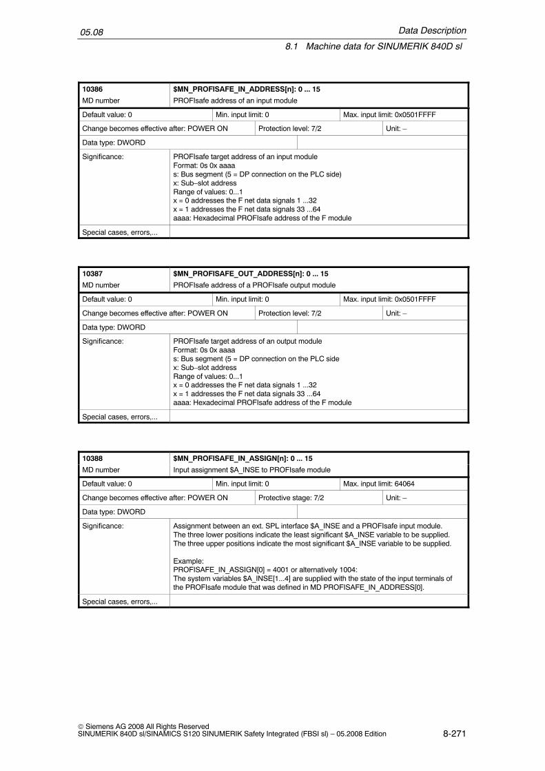
Data Description
8.1 Machine data for SINUMERIK 840D sl
05.08
8-271© Siemens AG 2008 All Rights ReservedSINUMERIK 840D sl/SINAMICS S120 SINUMERIK Safety Integrated (FBSI sl) – 05.2008 Edition
10386 $MN_PROFISAFE_IN_ADDRESS[n]: 0 ... 15
MD number PROFIsafe address of an input module
Default value: 0 Min. input limit: 0 Max. input limit: 0x0501FFFF
Change becomes effective after: POWER ON Protection level: 7/2 Unit: –
Data type: DWORD
Significance: PROFIsafe target address of an input moduleFormat: 0s 0x aaaas: Bus segment (5 = DP connection on the PLC side)x: Sub–slot addressRange of values: 0...1x = 0 addresses the F net data signals 1 ...32x = 1 addresses the F net data signals 33 ...64aaaa: Hexadecimal PROFIsafe address of the F module
Special cases, errors,...
10387 $MN_PROFISAFE_OUT_ADDRESS[n]: 0 ... 15
MD number PROFIsafe address of a PROFIsafe output module
Default value: 0 Min. input limit: 0 Max. input limit: 0x0501FFFF
Change becomes effective after: POWER ON Protection level: 7/2 Unit: –
Data type: DWORD
Significance: PROFIsafe target address of an output moduleFormat: 0s 0x aaaas: Bus segment (5 = DP connection on the PLC sidex: Sub–slot addressRange of values: 0...1x = 0 addresses the F net data signals 1 ...32x = 1 addresses the F net data signals 33 ...64aaaa: Hexadecimal PROFIsafe address of the F module
Special cases, errors,...
10388 $MN_PROFISAFE_IN_ASSIGN[n]: 0 ... 15
MD number Input assignment $A_INSE to PROFIsafe module
Default value: 0 Min. input limit: 0 Max. input limit: 64064
Change becomes effective after: POWER ON Protective stage: 7/2 Unit: –
Data type: DWORD
Significance: Assignment between an ext. SPL interface $A_INSE and a PROFIsafe input module.The three lower positions indicate the least significant $A_INSE variable to be supplied.The three upper positions indicate the most significant $A_INSE variable to be supplied.
Example:PROFISAFE_IN_ASSIGN[0] = 4001 or alternatively 1004:The system variables $A_INSE[1...4] are supplied with the state of the input terminals ofthe PROFIsafe module that was defined in MD PROFISAFE_IN_ADDRESS[0].
Special cases, errors,...

Data Description
8.1 Machine data for SINUMERIK 840D sl
05.08
8-272© Siemens AG 2008 All Rights Reserved
SINUMERIK 840D sl/SINAMICS S120 SINUMERIK Safety Integrated (FBSI sl) – 05.2008 Edition
10389 $MN_PROFISAFE_OUT_ASSIGN[n]: 0 ... 15
MD number Output assignment, $A_OUTSE to PROFIsafe module
Default value: 0 Min. input limit: 0 Max. input limit: 64064
Change becomes effective after: POWER ON Protective stage: 7/2 Unit: –
Data type: DWORD
Significance: Assignment between an ext. SPL interface $A_OUTSE and a PROFIsafe output module.The three lower positions indicate the least significant $A_OUTSE variable to be con-nected.The three upper positions indicate the most significant $A_OUTSE variable to be con-nected.
Example:PROFISAFE_OUT_ASSIGN[0] = 64061 or alternatively 61064:The system variables $A_OUTSE[61...64] are placed at the output terminals of the PROFI-safe module defined in MD PROFISAFE_OUT_ADDRESS[0].
Special cases, errors,...
10393 $MN_SAFE_DRIVE_LOGIC_ADDRESS
MD number Logical drive addresses, SI
Default value: 6700, 6724, 6748, 6772,6796, 6820, 6844, 6868, 6892, 6916,6940, 6964, 6988, 7012, 7036, 7060,7084, 7108, 7132, 7156, 7180, 7204,7228, 7252, 7276, 7300, 7324, 7348,7372, 7396, 7420, 7444, 7468, 7492,7516, 7540, 7564
Min. input limit: 258 Max. input limit: 8191
Change becomes effective after: POWER ON Protection level: 7/2 Unit: –
Data type: DWORD
Significance: Logical I/O addresses of the SI telegram of drives connected to PROFIBUS. An address isassigned to a drive.
Special cases, errors,...

Data Description
8.1 Machine data for SINUMERIK 840D sl
05.08
8-273© Siemens AG 2008 All Rights ReservedSINUMERIK 840D sl/SINAMICS S120 SINUMERIK Safety Integrated (FBSI sl) – 05.2008 Edition
13300 $MN_PROFISAFE_IN_FILTER
MD number F useful (net) data filter IN
Default value: 0xFFFFFFFF Min. input limit: – Max. input limit: –
Change becomes effective after: POWER ON Protection level: 7/2 Unit: –
Data type: DWORD
Significance: Filter between F net (useful) data and $A_INSE variables
The machine data: $MN_PROFISAFE_IN_FILTER is used to define which F net data bitsof the PROFIsafe module are accepted for further processing from the F net data interfaceof the PROFIsafe module in the NCK.
The filtered F net data bits are pushed together inside the NCK to form a bit array withoutany gaps (consecutive bit array).
The machine data: $MN_PROFISAFE_IN_ASSIGN is then used to define in which $INSEvariables, the filtered F net data bits are transferred.
Example:Note: For reasons of simplicity, only 16 bits are taken into consideration.Parameter assignment:
PROFISAFE_IN_FILTER = 1010100101000100PROFISAFE_IN_ASSIGN = 011006
n = 16 11 6 1
1010 1000 0000 0100 value at the F net data interface of the PROFIsafe module
1010 1001 0100 0100 $MN_PROFISAFE_IN_FILTER
0000 0000 0011 1001 internal NCK F net data imagexxxx x111 001x xxxx $INSE[n], x = not relevant
corresponds with ...
Additional references

Data Description
8.1 Machine data for SINUMERIK 840D sl
05.08
8-274© Siemens AG 2008 All Rights Reserved
SINUMERIK 840D sl/SINAMICS S120 SINUMERIK Safety Integrated (FBSI sl) – 05.2008 Edition
13301 $MN_PROFISAFE_OUT_FILTER
MD number F net (useful) data filter OUT
Default value 0xFFFFFFFF Min. input limit: – Max. input limit: –
Change becomes effective after: POWER ON Protection level: 7/2 Unit: –
Data type: DWORD
Significance: Filter between $A_OUTSE variables and F net (useful) data
The machine data: PROFISAFE_OUT_ASSIGN is used to define which $A_OUTSE[n]variables are transferred into the F net data bits of the PROFIsafe module.
The machine data: PROFISAFE_OUT_FILTER is used to define which F net data bit istransferred to the particular $A_OUTSE[n] variable.
Example:Note: For reasons of simplicity, only 16 bits are taken into consideration.Parameter assignment:
$MN_PROFISAFE_OUT_FILTER = 1010100101000100$MN_PROFISAFE_OUT_ASSIGN = 011006
n = 16 11 6 1xxxx x111 111x xxxx example value in the $OUTSE variables, x not relevant
0000 0000 0011 1111 internal NCK F net data image
1010 1001 0100 0100 $MN_PROFISAFE_OUT_FILTER
1010 1001 0100 0100 F net data of the PROFIsafe module
corresponds with ...
Additional references
13310 $MN_SAFE_SPL_START_TIMEOUT
MD number Delay, display Alarm 27097
Default value 20. Min. input limit: 1. Max. input limit: 60.
Change becomes effective after: POWER ON Protection level: 7/2 Unit: s
Data type: DOUBLE
Significance: After the control has booted, after the time has expired, Alarm 27097 is displayed if therewas no SPL start.
corresponds with ...
Additional references

Data Description
8.1 Machine data for SINUMERIK 840D sl
05.08
8-275© Siemens AG 2008 All Rights ReservedSINUMERIK 840D sl/SINAMICS S120 SINUMERIK Safety Integrated (FBSI sl) – 05.2008 Edition
20108 $MC_PROG_EVENT_MASK
MD number Event–controlled program call
Default value (0x0, 0x0,...) Min. input limit: 0 Max. input limit: 0xF
Change becomes effective after: POWER ON Protection level: 7/2 Unit: –
Data type: DWORD
Significance: Parameterizes the event where the user program, set with $MN_PROG_EVENT_NAME(default: _N_PROG_EVENT_SPF) is implicitly called:Bit 0 = 1: Part program startBit 1 = 1: Part program endBit 2 = 1: Operator panel resetBit 3 = 1: BootThe user program is called using the following search path:1. /_N_CUS_DIR/_NPROG_EVENT_SPF2. /_N_CMA_DIR/_NPROG_EVENT_SPF3. /_N_CST_DIR/_NPROG_EVENT_SPF
corresponds with ...
Additional references
28251 $MC_MM_NUM_SAFE_SYNC_ELEMENTS
MD number Number of elements for expressions in safety synchronized actions
Default value 0 Min. input limit: 0 Max. input limit: 32000
Change becomes effective after: POWER ON Protection level: 7/2 Unit: –
Data type: DWORD
Significance: The expressions of motion synchronizing actions are saved in storage elements in thecontrol system. A motion synchronizing action requires a minimum of 4 elements.The assignments are as follows:each operand in the condition: 1 elementeach action: >= 1 elementeach assignment: 2 elementseach additional operand in complex expressions: 1 elementSee also: MD 28250: $MC_MM_NUM_SYNC_ELEMENTS
corresponds with ...
Additional references

Data Description
8.1 Machine data for SINUMERIK 840D sl
05.08
8-276© Siemens AG 2008 All Rights Reserved
SINUMERIK 840D sl/SINAMICS S120 SINUMERIK Safety Integrated (FBSI sl) – 05.2008 Edition
36901 $MA_SAFE_FUNCTION_ENABLE
MD number Enable safety–related functions
Default value: 0 Min. input limit: 0 Max. input limit: 0xFFFB
Change becomes effective after: POWER ON Protection level: 7/2 Unit: –
Data type: DWORD
Significance: The functions for safe operation can be enabled for one axis/spindle using this machinedata.It is only possible to enable – on an axis–specific basis – as many axes/spindles for safeoperation as have been enabled by the global option.The more partial functions that are set then the more computing time the safe functionsrequire.Bit 0: Enable safely reduced speed, safe operating stopBit 1: Enable safe limit switchesBit 2: Reserved for functions with absolute reference (such as SE/SN)Bit 3: Enable actual value synchronization, 2–encoder systemBit 4: Enable external ESR activation (STOP E)Bit 5: Enable SG correctionBit 6: Enable the external stop requests/external STOPsBit 7: Enable cam synchronizationBit 8: Enable safe cam, pair 1, cam+Bit 9: Enable safe cam, pair 1, cam–Bit 10: Enable safe cam, pair 2, cam+Bit 11: Enable safe cam, pair 2, cam–Bit 12: Enable safe cam, pair 3, cam+Bit 13: Enable safe cam, pair 3, cam–Bit 14: Enable safe cam, pair 4, cam+Bit 15: Enable safe cam, pair 4, cam–
Special cases, errors,... – If bit 1 or a higher bit is set, then bit 0 must also be set since the control systemswitches to a safe operational stop in response to STOP C, D or E (a parameteriza-tion alarm 27033 is output if an error is detected).
– If an insufficient number of axes/spindles have been enabled for safe operation usingthe global option, then this data may be overwritten with the value 0000 when boot-ing.
corresponds with ... Global option
Additional references /FBSI/ see Chapter: 5.5, ”Enabling safety–related functions”
36902 $MA_SAFE_IS_ROT_AX
MD number Rotary axis
Default value: FALSE Min. input limit: – Max. input limit: –
Change becomes effective after: POWER ON Protection level: 7/2 Unit: –
Data type: BOOLEAN
Significance: This data specifies whether the axis for safe operation is a rotary axis/spindle or linear axis.= 0: Linear axis= 1: Rotary axis/spindleThe value set in this MD must be the same as the value set in MD $MA_IS_ROT_AX. Ifthey are not identical a parameterizing error is displayed.
corresponds with ...

Data Description
8.1 Machine data for SINUMERIK 840D sl
05.08
8-277© Siemens AG 2008 All Rights ReservedSINUMERIK 840D sl/SINAMICS S120 SINUMERIK Safety Integrated (FBSI sl) – 05.2008 Edition
36903 $MA_SAFE_CAM_ENABLE
MD number Enable safe cam track
Default value: 0 Min. input limit: 0 Max. input limit: 0x3FFFFFFF
Change becomes effective after: POWER ON Protection level: 7/2 Unit: –
Data type: DWORD
Significance: 30 safe cams can be enabled for one axis/spindle for the ”safe cam track” function usingthis machine data.The enable signals may only be issued if the cam enable is not used in $MA_SAFE_FUNC-TION_ENABLE.The cam synchronization is automatically activated if the ”safe cam track” function is en-abled.Bit 0: Enable safe cam track, cam 1Bit 1: Enable safe cam track, cam 2Bit 2: Enable safe cam track, cam 3Bit 3: Enable safe cam track, cam 4Bit 4: Enable safe cam track, cam 5Bit 5: Enable safe cam track, cam 6Bit 6: Enable safe cam track, cam 7Bit 7: Enable safe cam track, cam 8Bit 8: Enable safe cam track, cam 9Bit 9: Enable safe cam track, cam 10Bit 10: Enable safe cam track, cam 11Bit 11: Enable safe cam track, cam 12Bit 12: Enable safe cam track, cam 13Bit 13: Enable safe cam track, cam 14Bit 14: Enable safe cam track, cam 15Bit 15: Enable safe cam track, cam 16Bit 16: Enable safe cam track, cam 17Bit 17: Enable safe cam track, cam 18Bit 18: Enable safe cam track, cam 19Bit 19: Enable safe cam track, cam 20Bit 20: Enable safe cam track, cam 21Bit 21: Enable safe cam track, cam 22Bit 22: Enable safe cam track, cam 23Bit 23: Enable safe cam track, cam 24Bit 24: Enable safe cam track, cam 25Bit 25: Enable safe cam track, cam 26Bit 26: Enable safe cam track, cam 27Bit 27: Enable safe cam track, cam 28Bit 28: Enable safe cam track, cam 29Bit 29: Enable safe cam track, cam 30
corresponds with ... /FBSI/ see Chapter 6.8: ”Safe software cams, safe cam track (SN)”
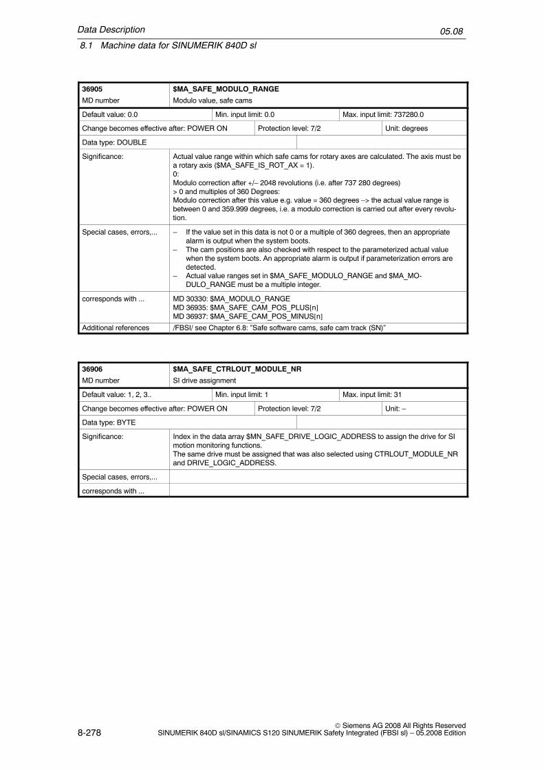
Data Description
8.1 Machine data for SINUMERIK 840D sl
05.08
8-278© Siemens AG 2008 All Rights Reserved
SINUMERIK 840D sl/SINAMICS S120 SINUMERIK Safety Integrated (FBSI sl) – 05.2008 Edition
36905 $MA_SAFE_MODULO_RANGE
MD number Modulo value, safe cams
Default value: 0.0 Min. input limit: 0.0 Max. input limit: 737280.0
Change becomes effective after: POWER ON Protection level: 7/2 Unit: degrees
Data type: DOUBLE
Significance: Actual value range within which safe cams for rotary axes are calculated. The axis must bea rotary axis ($MA_SAFE_IS_ROT_AX = 1).0:Modulo correction after +/– 2048 revolutions (i.e. after 737 280 degrees)> 0 and multiples of 360 Degrees:Modulo correction after this value e.g. value = 360 degrees –> the actual value range isbetween 0 and 359.999 degrees, i.e. a modulo correction is carried out after every revolu-tion.
Special cases, errors,... – If the value set in this data is not 0 or a multiple of 360 degrees, then an appropriatealarm is output when the system boots.
– The cam positions are also checked with respect to the parameterized actual valuewhen the system boots. An appropriate alarm is output if parameterization errors aredetected.
– Actual value ranges set in $MA_SAFE_MODULO_RANGE and $MA_MO-DULO_RANGE must be a multiple integer.
corresponds with ... MD 30330: $MA_MODULO_RANGEMD 36935: $MA_SAFE_CAM_POS_PLUS[n]MD 36937: $MA_SAFE_CAM_POS_MINUS[n]
Additional references /FBSI/ see Chapter 6.8: ”Safe software cams, safe cam track (SN)”
36906 $MA_SAFE_CTRLOUT_MODULE_NR
MD number SI drive assignment
Default value: 1, 2, 3.. Min. input limit: 1 Max. input limit: 31
Change becomes effective after: POWER ON Protection level: 7/2 Unit: –
Data type: BYTE
Significance: Index in the data array $MN_SAFE_DRIVE_LOGIC_ADDRESS to assign the drive for SImotion monitoring functions.The same drive must be assigned that was also selected using CTRLOUT_MODULE_NRand DRIVE_LOGIC_ADDRESS.
Special cases, errors,...
corresponds with ...

Data Description
8.1 Machine data for SINUMERIK 840D sl
05.08
8-279© Siemens AG 2008 All Rights ReservedSINUMERIK 840D sl/SINAMICS S120 SINUMERIK Safety Integrated (FBSI sl) – 05.2008 Edition
36907 $MA_SAFE_DRIVE_PS_ADDRESS
MD number PROFIsafe address of the drive
Default value: 0 Min. input limit: – Max. input limit: –
Change becomes effective after: POWER ON Protection level: 7/0 Unit: –
Data type: DWORD
Significance: This NCK–MD contains the PROFIsafe address of the drive assigned to this axis. Whenbooting, the drive reads out this MD. The address must be unique across all of the axes.This MD cannot be written to; the PROFIsafe address must be parameterized in the drive.The value of this MD is incorporated in the calculation of MD $MA_SAFE_ACT_CHECK-SUM[1].
Special cases, errors,...
corresponds with ...
36912 $MA_SAFE_ENC_INPUT_NR
MD number Actual value assignment: Input on drive module/measuring circuit card
Default value: 1 Min. input limit: 1 Max. input limit: 3
Change becomes effective after: POWER ON Protection level: 7/2 Unit: –
Data type: BYTE
Significance: Number of the actual value input of a module via which the SI1: SI encoder is connected to the upper input (motor encoder)2: SI encoder is connected to the lower input
Special cases, errors,...
corresponds with ... p9526, p0189,
36914 $MA_SAFE_SINGLE_ENC
MD number SI single–encoder system
Default value: TRUE Min. input limit: – Max. input limit: –
Change becomes effective after: POWER ON Protection level: 7/2 Unit: –
Data type: BOOLEAN
Significance: ID that SI is carried out with an encoder. If different encoders are used for the Safety Inte-grated monitoring functions in the drive and in the NCK, then this MD must be parameter-ized to be 0.
Special cases, errors,...
corresponds with ...

Data Description
8.1 Machine data for SINUMERIK 840D sl
05.08
8-280© Siemens AG 2008 All Rights Reserved
SINUMERIK 840D sl/SINAMICS S120 SINUMERIK Safety Integrated (FBSI sl) – 05.2008 Edition
36916 $MA_SAFE_ENC_IS_LINEAR
MD number Linear scale
Default value: 0 Min. input limit: 0 Max. input limit: 1
Change becomes effective after: POWER ON Protection level: 7/2 Unit: –
Data type: BOOLEAN
Significance: This MD specifies whether a linear or a rotary encoder is connected.= 0:A rotary encoder is connected, $MA_SAFE_ENC_RESOL is used to specify its resolutionand $MA_SAFE_ENC_GEAR_PITCH, $MA_SAFE_ENC_GEAR_DENOM[n] and$MA_SAFE_ENC_GEAR_NUMERA[n] are used to convert it to the load side.The MD: $MA_SAFE_ENC_GRID_POINT_DIST has no significance.= 1:Linear encoder is connected, $MA_SAFE_ENC_GRID_POINT_DIST is used to specify itsresolution.The MDs: $MA_SAFE_ENC_RESOL, $MA_SAFE_ENC_GEAR_PITCH,$MA_SAFE_ENC_GEAR_DENOM[n] and $MA_SAFE_ENC_GEAR_NUMERA[n] have nosignificance.This MD cannot be written to, the encoder type must be parameterized in the drive.If the value changes then Alarm 27036 is output.
corresponds with ... For 0:$MA_SAFE_ENC_RESOL$MA_SAFE_ENC_GEAR_PITCH$MA_SAFE_ENC_GEAR_DENOM[n]$MA_SAFE_ENC_GEAR_NUMERA[n]For 1:$MA_SAFE_ENC_GRID_POINT_DIST
36917 $MA_SAFE_ENC_GRID_POINT_DIST
MD number Grid spacing, linear scale
Default value: 0.01 Min. input limit: 0.000 01 Max. input limit: 8
Change becomes effective after: POWER ON Protection level: 7/2 Unit: mm
Data type: DOUBLE
Significance: This MD specifies the grid spacing of the linear scale used here.Not relevant for rotary encoders.
corresponds with ...
36918 $MA_SAFE_ENC_RESOL
MD number Encoder pulses per revolution
Default value: 2 048 Min. input limit: 1 Max. input limit: 100 000
Change becomes effective after: POWER ON Protection level: 7/2 Unit: –
Data type: DWORD
Significance: This MD specifies the number of pulses per revolution for a rotary encoder.Not relevant for a linear encoder.
corresponds with ...

Data Description
8.1 Machine data for SINUMERIK 840D sl
05.08
8-281© Siemens AG 2008 All Rights ReservedSINUMERIK 840D sl/SINAMICS S120 SINUMERIK Safety Integrated (FBSI sl) – 05.2008 Edition
36919 $MA_SAFE_ENC_PULSE_SHIFT
MD number Shift factor of the encoder multiplication
Default value: 11 Min. input limit: 2 Max. input limit: 18
Change becomes effective after: POWER ON Protection level: 7/2 Unit: –
Data type: BYTE
Significance: Shift factor of the multiplication (resolution) of the encoder, that is used for the Safety Inte-grated monitoring functions in the NCK. The encoder value must be divided by 2 so manytimes (shift factor) in order to obtain the number of encoder pulses. A shift factor of 11 cor-responds to an encoder multiplication by a factor of 2048. If the drive provides this informa-tion (r0979[3,13,23]), then this MD is automatically internally assigned a value after thedrive has run up. If the value changes then Alarm 27036 is output.
corresponds with ...
36920 $MA_SAFE_ENC_GEAR_PITCH
MD number Leadscrew pitch
Default value: 10.0 Min. input limit: 0.1 Max. input limit: 10000.
Change becomes effective after: POWER ON Protection level: 7/2 Unit: mm
Data type: DOUBLE
Significance: Gear ratio of the gearbox (gear) between the encoder and load for a linear axis with rotaryencoder.
corresponds with ...
36921 $MA_SAFE_ENC_GEAR_DENOM[n]: 0 ... 7
MD number Denominator, gearbox ratio encoder/load
Default value: 1 Min. input limit: 1 Max. input limit: 2 147 000 000
Change becomes effective after: POWER ON Protection level: 7/2 Unit: –
Data type: DWORD
Significance: Denominator of the gear between encoder and load, i.e. the denominator of the fractionnumber of encoder revolutions/number of load revolutionsn= 0, 1, ... ,7 stands for gearbox stages 1, 2, ... 8The actual value is selected using safety–related input signals (SGE).
corresponds with ... MD 36922: $MA_SAFE_ENC_GEAR_NUMERA[n]
36922 $MA_SAFE_ENC_GEAR_NUMERA[n]: 0 ... 7
MD number Numerator, gearbox ratio encoder/load
Default value: 1 Min. input limit: 1 Max. input limit: 2 147 000 000
Change becomes effective after: POWER ON Protection level: 7/2 Unit: –
Data type: DWORD
Significance: Numerator of the gear between encoder and load, i.e. the numerator of the fraction numberof encoder revolutions/number of load revolutions”n= 0, 1, ... 7 stands for gearbox stages 1, 2, ... 8The actual value is selected using safety–related input signals (SGE).
corresponds with ... MD 36921: $MA_SAFE_ENC_GEAR_DENOM[n]
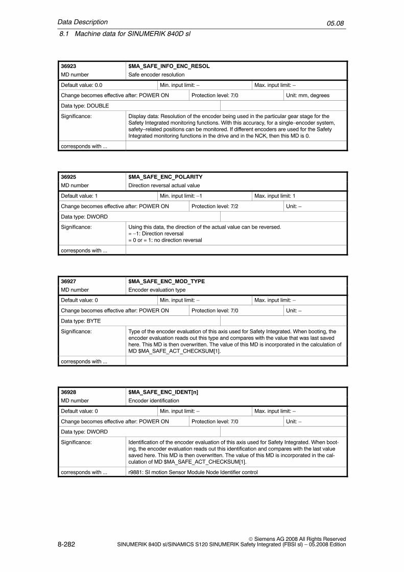
Data Description
8.1 Machine data for SINUMERIK 840D sl
05.08
8-282© Siemens AG 2008 All Rights Reserved
SINUMERIK 840D sl/SINAMICS S120 SINUMERIK Safety Integrated (FBSI sl) – 05.2008 Edition
36923 $MA_SAFE_INFO_ENC_RESOL
MD number Safe encoder resolution
Default value: 0.0 Min. input limit: – Max. input limit: –
Change becomes effective after: POWER ON Protection level: 7/0 Unit: mm, degrees
Data type: DOUBLE
Significance: Display data: Resolution of the encoder being used in the particular gear stage for theSafety Integrated monitoring functions. With this accuracy, for a single–encoder system,safety–related positions can be monitored. If different encoders are used for the SafetyIntegrated monitoring functions in the drive and in the NCK, then this MD is 0.
corresponds with ...
36925 $MA_SAFE_ENC_POLARITY
MD number Direction reversal actual value
Default value: 1 Min. input limit: –1 Max. input limit: 1
Change becomes effective after: POWER ON Protection level: 7/2 Unit: –
Data type: DWORD
Significance: Using this data, the direction of the actual value can be reversed.= –1: Direction reversal= 0 or = 1: no direction reversal
corresponds with ...
36927 $MA_SAFE_ENC_MOD_TYPE
MD number Encoder evaluation type
Default value: 0 Min. input limit: – Max. input limit: –
Change becomes effective after: POWER ON Protection level: 7/0 Unit: –
Data type: BYTE
Significance: Type of the encoder evaluation of this axis used for Safety Integrated. When booting, theencoder evaluation reads out this type and compares with the value that was last savedhere. This MD is then overwritten. The value of this MD is incorporated in the calculation ofMD $MA_SAFE_ACT_CHECKSUM[1].
corresponds with ...
36928 $MA_SAFE_ENC_IDENT[n]
MD number Encoder identification
Default value: 0 Min. input limit: – Max. input limit: –
Change becomes effective after: POWER ON Protection level: 7/0 Unit: –
Data type: DWORD
Significance: Identification of the encoder evaluation of this axis used for Safety Integrated. When boot-ing, the encoder evaluation reads out this identification and compares with the last valuesaved here. This MD is then overwritten. The value of this MD is incorporated in the cal-culation of MD $MA_SAFE_ACT_CHECKSUM[1].
corresponds with ... r9881: SI motion Sensor Module Node Identifier control

Data Description
8.1 Machine data for SINUMERIK 840D sl
05.08
8-283© Siemens AG 2008 All Rights ReservedSINUMERIK 840D sl/SINAMICS S120 SINUMERIK Safety Integrated (FBSI sl) – 05.2008 Edition
36930 $MA_SAFE_STANDSTILL_TOL
MD number Zero speed tolerance
Default value: 1. Min. input limit: 0. Max. input limit: 100.
Change becomes effective after: POWER ON Protection level: 7/2 Unit: mm, degrees
Data type: DOUBLE
Significance: This MD specifies the tolerance for a safe operating stop.If the difference between the position limit value and position actual value is greater thanthe tolerance set here when a safe operating stop is selected, then the control system out-puts Alarm 27010 with STOP B. The position limit value is the position actual value at theinstant that a safe operating stop is selected.
corresponds with ... MD 36956: $MA_SAFE_PULSE_DISABLE_DELAY
36931 $MA_SAFE_VELO_LIMIT[n]: 0 ... 3
MD number Limit value for safely reduced speed
Default value: 2000. Min. input limit: – Max. input limit: –
Change becomes effective after: POWER ON Protection level: 7/2 Unit: mm/min, rev/min
Data type: DOUBLE
Significance: This MD defines the limit values for safely reduced speeds 1, 2, 3 and 4.When SG1, SG2, SG3 or SG4 is selected and the actual speed exceeds this limit value,then the control system outputs Alarm 27011 with the stop response configured in$MA_SAFE_VELO_STOP_MODE or $MA_SAFE_VELO_STOP_REACTION.n = 0, 1, 2, 3 stands for the limit value of SG1, SG2, SG3, SG4
Special cases, errors,... When SBH/SG is active in a 1–encoder system, the speed is monitored corresponding tothe encoder limit frequency set in MD $MA_SAFE_ENC_FREQ_LIMIT. An appropriatealarm is output if this limit is exceeded.
corresponds with ... MD 36961: $MA_SAFE_VELO_STOP_MODEMD 36963: $MA_SAFE_VELO_STOP_REACTION
36932 $MA_SAFE_VELO_OVR_FACTOR[n]: 0 ... 15
MD number SG selection values
Default value: 100.0 Min. input limit: 1.0 Max. input limit: 100.0
Change becomes effective after: POWER ON Protection level: 7/2 Unit: %
Data type: DOUBLE
Significance: Limit value corrections for the safely reduced speeds 2 and 4 can be selected using SGEsand the associated correction value (percentage value) set using this MD.n = 0, 1, ... , 15 stands for correction 0, 1, ... 15
Special cases, errors,... � The ”Correction for safely reduced speed” function is enabled using MD 36901$MA_SAFE_FUNCTION_ENABLE.
� This correction has no effect for the limit values associated with safely reduced speeds1 and 3.
Additional references MD 36978: $MA_SAFE_OVR_INPUT[n]MD 36931: $MA_SAFE_VELO_LIMIT[n]
Additional references /FBSI/ see Chapter 6.5.4: ”Override for safely reduced speed”
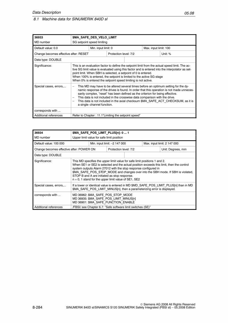
Data Description
8.1 Machine data for SINUMERIK 840D sl
05.08
8-284© Siemens AG 2008 All Rights Reserved
SINUMERIK 840D sl/SINAMICS S120 SINUMERIK Safety Integrated (FBSI sl) – 05.2008 Edition
36933 $MA_SAFE_DES_VELO_LIMIT
MD number SG setpoint speed limiting
Default value: 0.0 Min. input limit: 0 Max. input limit: 100
Change becomes effective after: RESET Protection level: 7/2 Unit: %
Data type: DOUBLE
Significance: This is an evaluation factor to define the setpoint limit from the actual speed limit. The ac-tive SG limit value is evaluated using this factor and is entered into the interpolator as set-point limit. When SBH is selected, a setpoint of 0 is entered.When 100% is entered, the setpoint is limited to the active SG stageWhen 0% is entered the setpoint speed limiting is not active.
Special cases, errors,... – This MD may have to be altered several times before an optimum setting for the dy-namic response of the drives is found. In order that this operation is not made unneces-sarily complex, ”reset” has been defined as the criterion for being effective.
– This data is not included in the crosswise data comparison with the drive.– This data is not included in the axial checksum $MA_SAFE_ACT_CHECKSUM, as it is
a single–channel function.
corresponds with ...
Additional references Refer to Chapter : 11.1”Limiting the setpoint speed”
36934 $MA_SAFE_POS_LIMIT_PLUS[n]: 0 ... 1
MD number Upper limit value for safe limit position
Default value: 100 000 Min. input limit: –2 147 000 Max. input limit: 2 147 000
Change becomes effective after: POWER ON Protection level: 7/2 Unit: Degrees, mm
Data type: DOUBLE
Significance: This MD specifies the upper limit value for safe limit positions 1 and 2.When SE1 or SE2 is selected and the actual position exceeds this limit, then the controlsystem outputs Alarm 27012 with the stop response configured in$MA_SAFE_POS_STOP_MODE and changes over into the SBH mode. If SBH is violated,STOP B and A are initiated as stop response.n = 0, 1 stand for the upper limit value of SE1, SE2
Special cases, errors,... If a lower or identical value is entered in MD $MD_SAFE_POS_LIMIT_PLUS[n] than in MD$MA_SAFE_POS_LIMIT_MINUS[n], then a parameterizing error is displayed.
corresponds with ... MD 36962: $MA_SAFE_POS_STOP_MODEMD 36935: $MA_SAFE_POS_LIMIT_MINUS[n]MD 36901: $MA_SAFE_FUNCTION_ENABLE
Additional references /FBSI/ see Chapter 6.7: ”Safe software limit switches (SE)”
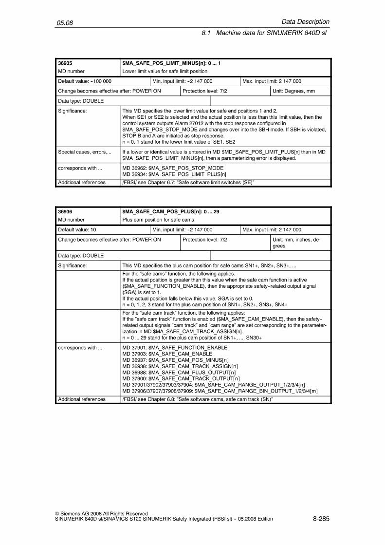
Data Description
8.1 Machine data for SINUMERIK 840D sl
05.08
8-285© Siemens AG 2008 All Rights ReservedSINUMERIK 840D sl/SINAMICS S120 SINUMERIK Safety Integrated (FBSI sl) -- 05.2008 Edition
36935 $MA_SAFE_POS_LIMIT_MINUS[n]: 0 ... 1
MD number Lower limit value for safe limit position
Default value: --100 000 Min. input limit: --2 147 000 Max. input limit: 2 147 000
Change becomes effective after: POWER ON Protection level: 7/2 Unit: Degrees, mm
Data type: DOUBLE
Significance: This MD specifies the lower limit value for safe end positions 1 and 2.When SE1 or SE2 is selected and the actual position is less than this limit value, then thecontrol system outputs Alarm 27012 with the stop response configured in$MA_SAFE_POS_STOP_MODE and changes over into the SBH mode. If SBH is violated,STOP B and A are initiated as stop response.n = 0, 1 stand for the lower limit value of SE1, SE2
Special cases, errors,... If a lower or identical value is entered in MD $MD_SAFE_POS_LIMIT_PLUS[n] than in MD$MA_SAFE_POS_LIMIT_MINUS[n], then a parameterizing error is displayed.
corresponds with ... MD 36962: $MA_SAFE_POS_STOP_MODEMD 36934: $MA_SAFE_POS_LIMIT_PLUS[n]
Additional references /FBSI/ see Chapter 6.7: ”Safe software limit switches (SE)”
36936 $MA_SAFE_CAM_POS_PLUS[n]: 0 ... 29
MD number Plus cam position for safe cams
Default value: 10 Min. input limit: --2 147 000 Max. input limit: 2 147 000
Change becomes effective after: POWER ON Protection level: 7/2 Unit: mm, inches, de-grees
Data type: DOUBLE
Significance: This MD specifies the plus cam position for safe cams SN1+, SN2+, SN3+, ...
For the ”safe cams” function, the following applies:If the actual position is greater than this value when the safe cam function is active($MA_SAFE_FUNCTION_ENABLE), then the appropriate safety--related output signal(SGA) is set to 1.If the actual position falls below this value, SGA is set to 0.n = 0, 1, 2, 3 stand for the plus cam position of SN1+, SN2+, SN3+, SN4+
For the ”safe cam track” function, the following applies:If the ”safe cam track” function is enabled ($MA_SAFE_CAM_ENABLE), then the safety--related output signals ”cam track” and ”cam range” are set corresponding to the parameter-ization in MD $MA_SAFE_CAM_TRACK_ASSIGN[n].n = 0 ... 29 stand for the plus cam position of SN1+, ..., SN30+
corresponds with ... MD 37901: $MA_SAFE_FUNCTION_ENABLEMD 37903: $MA_SAFE_CAM_ENABLEMD 36937: $MA_SAFE_CAM_POS_MINUS[n]MD 36938: $MA_SAFE_CAM_TRACK_ASSIGN[n]MD 36988: $MA_SAFE_CAM_PLUS_OUTPUT[n]MD 37900: $MA_SAFE_CAM_TRACK_OUTPUT[n]MD 37901/37902/37903/37904: $MA_SAFE_CAM_RANGE_OUTPUT_1/2/3/4[n]MD 37906/37907/37908/37909: $MA_SAFE_CAM_RANGE_BIN_OUTPUT_1/2/3/4[m]
Additional references /FBSI/ see Chapter 6.8: ”Safe software cams, safe cam track (SN)”

Data Description
8.1 Machine data for SINUMERIK 840D sl
05.08
8-286© Siemens AG 2008 All Rights Reserved
SINUMERIK 840D sl/SINAMICS S120 SINUMERIK Safety Integrated (FBSI sl) -- 05.2008 Edition
36937 $MA_SAFE_CAM_POS_MINUS[n]: 0 ... 29
MD number Minus cam position for safe cams
Default value: --10 Min. input limit: --2 147 000 Max. input limit: 2 147 000
Change becomes effective after: Power On Protection level: 7/2 Unit: mm, degrees
Data type: DOUBLE
Significance: This MD specifies the minus cam position for safe cams SN1--, SN2--, SN3--, ...
For the ”safe cams” function, the following applies:If the actual position is greater than this value when the safe cam function is active($MA_SAFE_FUNCTION_ENABLE), then the appropriate safety--related output signal(SGA) is set to 1.If the actual position falls below this value, SGA is set to 0.n = 0, 1, 2, 3 stand for the minus cam position of SN1--, SN2--, SN3--, SN4--
For the ”safe cam track” function, the following applies:If the ”safe cam track” function is enabled ($MA_SAFE_CAM_ENABLE), then the safety--related output signals ”cam track” and ”cam range” are set corresponding to the parameter-ization in MD $MA_SAFE_CAM_TRACK_ASSIGN[n].n = 0 ... 29 stand for the plus cam position of SN1--, ..., SN30--
corresponds with ... MD 37901: $MA_SAFE_FUNCTION_ENABLEMD 37903: $MA_SAFE_CAM_ENABLEMD 36937: $MA_SAFE_CAM_POS_PLUS[n]MD 36938: $MA_SAFE_CAM_TRACK_ASSIGN[n]MD 36988: $MA_SAFE_CAM_PLUS_OUTPUT[n]MD 37900: $MA_SAFE_CAM_TRACK_OUTPUT[n]MD 37901/37902/37903/37904: $MA_SAFE_CAM_RANGE_OUTPUT_1/2/3/4[n]MD 37906/37907/37908/37909: $MA_SAFE_CAM_RANGE_BIN_OUTPUT_1/2/3/4[m]
Additional references /FBSI/ see Chapter 6.8: ”Safe software cams, safe cam track (SN)”

Data Description
8.1 Machine data for SINUMERIK 840D sl
05.08
8-287© Siemens AG 2008 All Rights ReservedSINUMERIK 840D sl/SINAMICS S120 SINUMERIK Safety Integrated (FBSI sl) – 05.2008 Edition
36938 $MA_SAFE_CAM_TRACK_ASSIGN[n]: 0 ... 29
MD number Cam track assignment
Default value:100, 101, ... , 114; 200, 201, ..., 214
Min. input limit: 100 Max. input limit: 414
Change becomes effective after: Power On Protection level: 7/2 Unit: –
Data type: DWORD
Significance: Assigns the individual cams to a maximum of 4 cam tracks including defining the numericalvalue for the SGA ”cam range”.The ”hundreds” position defines which cam track is assigned to the cams. Valid values are1, 2 or 3 or 4.The ”tens” and ”ones” positions contain the numerical value that should be signaled to thesafe logic as SGA ”cam range” and processed there. Valid values are 0 to 14, wherebyeach numerical value may only be used once for each cam.Therefore the valid value range of this machine data is:100...114, 200...214, 300...314, 400...414Examples:MD 36938[0] = 207: Cam 1 (index 0) is assigned to cam track 2. If the position is in therange of this cam, then 7 is entered in the SGA ”cam range” of the 2nd cam track.MD 36938[5] = 100: Cam 6 (index 5) is assigned to cam track 1. If the position is in therange of this cam, then 0 is entered in the SGA ”cam range” of the 1st cam track.
corresponds with ... MD 37903: $MA_SAFE_CAM_ENABLEMD 36936: $MA_SAFE_CAM_POS_PLUS[n]MD 36937: $MA_SAFE_CAM_POS_MINUS[n]MD 37900: $MA_SAFE_CAM_TRACK_OUTPUT[n]MD 37901/37902/37903/37904: $MA_SAFE_CAM_RANGE_OUTPUT_1/2/3/4[n]MD 37906/37907/37908/37909: $MA_SAFE_CAM_RANGE_BIN_OUTPUT_1/2/3/4[m]
Additional references /FBSI/ see Chapter 6.8: ”Safe software cams, safe cam track (SN)”
36940 $MA_SAFE_CAM_TOL
MD number Tolerance for safe cams
Default value: 0.1 Min. input limit: 0.001 Max. input limit: 10
Change becomes effective after: POWER ON Protection level: 7/2 Unit: mm, degrees
Data type: DOUBLE
Significance: Due to the different mounting locations of the encoders and variations in clock cycle andsignal transit (propagation times), the cam signals of the two monitoring channels neverswitch at precisely the same position and never simultaneously.This data specifies the tolerances for all cams as a load–side distance. The monitoringchannels may have different signal states for the same cam within this tolerance bandwidthwithout generating Alarm 27001.Recommendation:Enter an identical or slightly higher value than that set in MD 36942.
Special cases, errors,...
Additional references /FBSI/ see Chapter 6.8: ”Safe software cams, safe cam track (SN)”

Data Description
8.1 Machine data for SINUMERIK 840D sl
05.08
8-288© Siemens AG 2008 All Rights Reserved
SINUMERIK 840D sl/SINAMICS S120 SINUMERIK Safety Integrated (FBSI sl) – 05.2008 Edition
36942 $MA_SAFE_POS_TOL
MD number Tolerance, actual value comparison (crosswise)
Default value: 0.1 Min. input limit: 0.001 Max. input limit: 360
Change becomes effective after: POWER ON Protection level: 7/2 Unit: mm, degrees
Data type: DOUBLE
Significance: Due to the fact that encoders are not mounted at identical locations and the effect of back-lash, torsion, leadscrew errors etc. the actual positions sensed simultaneously by the NCKand drive may differ from one another.The tolerance bandwidth for the crosswise comparison of the actual positions in the twomonitoring channels is specified in this machine data.
Special cases, errors,... � ”Finger protection” (approx. 10 mm) is the primary consideration when setting this toler-ance value.
� Stop response STOP F is activated when the tolerance bandwidth is violated.
36944 $MA_SAFE_REFP_POS_TOL
MD number Tolerance, actual value comparison (referencing)
Default value: 0.01 Min. input limit: 0 Max. input limit: 36
Change becomes effective after: POWER ON Protection level: 7/2 Unit: mm, degrees
Data type: DOUBLE
Significance: This machine data specifies the tolerance for checking the actual values after referencing(for incremental encoders) or when powering–up (for absolute encoders).An absolute actual axis position is determined by referencing.A second absolute actual position is calculated from the last stop position that was savedprior to the control being powered–down and the distance traversed since power–on. Thecontrol system checks the actual values after referencing on the basis of the two actualpositions, the traversed distance and this machine data.The following factors must be taken into consideration when calculating tolerance values:Backlash, leadscrew errors, compensation (max. compensation values for SSFK, sag andtemperature compensation), temperature errors, torsion (2–encoder system), gearbox playfor control gears, coarser resolution (2–encoder system), oscillating distance/range forcontrol gears.
Special cases, errors,... If these two absolute actual positions deviate from one another by more than the value setin this data – with a valid user agreement – then Alarm 27001 is output with Fault code1003 and a new user agreement is required for referencing.

Data Description
8.1 Machine data for SINUMERIK 840D sl
05.08
8-289© Siemens AG 2008 All Rights ReservedSINUMERIK 840D sl/SINAMICS S120 SINUMERIK Safety Integrated (FBSI sl) – 05.2008 Edition
36946 $MA_SAFE_VELO_X
MD number Speed limit nx
Default value: 20. Min. input limit: 0. Max. input limit: 6 000.
Change becomes effective after: POWER ON Protection level: 7/2 Unit:mm/min, rev/min
Data type: DOUBLE
Significance: This machine data defines the limit speed nx for the SGA ”n < nx”.If this velocity limit is fallen below, SGA ”n < nx” is set.
corresponds with ...
Additional references /FBSI/ see Chapter 6.6: ”SGA ”n < nx” and ”SG active””
36948 $MA_SAFE_STOP_VELO_TOL
MD number Speed tolerance for safe acceleration monitoring
Default value: 300. Min. input limit: 0. Max. input limit: 120 000.
Change becomes effective after: POWER ON Protection level: 7/2 Unit: mm/min, rev/min
Data type: DOUBLE
Significance: Actual speed tolerance for safe acceleration monitoring (SBR).After the safe acceleration monitoring has been activated (by initiating a Stop B or C), thenthis tolerance is applied to the actual speed.It is not permissible that the actual velocity is greater than the limit that is therefore speci-fied.Otherwise, a Stop A will be initiated. This means that if the drive accelerates, this will beidentified very quickly.
corresponds with ...
Additional references /FBSI/ see Chapter 6.4: ”Safe acceleration monitoring (SBR)”(a recommended setting and setting formula are specified in this Chapter).
36949 $MA_SAFE_SLIP_VELO_TOL
MD number Speed tolerance, slip
Default value: 6. Min. input limit: 0. Max. input limit: 6000.
Change becomes effective after: POWER ON Protection level: 7/2 Unit:mm/min, rev/min
Data type: DOUBLE
Significance: Speed difference that, for a 2–encoder system, is tolerated between the motor and loadsides without the crosswise data comparison between the drive and NCK signaling anerror.MD 36949 is only evaluated if MD $MA_SAFE_FUNCTION_ENABLE, bit 3 is set.
corresponds with ...
Additional references /FBSI/ see Chapter 5.4.6: Actual value synchronization

Data Description
8.1 Machine data for SINUMERIK 840D sl
05.08
8-290© Siemens AG 2008 All Rights Reserved
SINUMERIK 840D sl/SINAMICS S120 SINUMERIK Safety Integrated (FBSI sl) – 05.2008 Edition
36950 $MA_SAFE_MODE_SWITCH_TIME
MD number Tolerance time for SGE changeover
Default value: 0.5 Min. input limit: 0 Max. input limit: 10.
Change becomes effective after: POWER ON Protection level: 7/2 Unit: s
Data type: DOUBLE
Significance: SGE changeover operations do not take effect simultaneously owing to variations in runtimes (propagation times) for SGE data transmission in the two monitoring channels. Acrosswise data comparison would, in this case, output an error message.This data is used to specify the period of time after SGE changeover operations duringwhich no crosswise comparison of actual values and monitoring results is carried out (ma-chine data is still compared!). The selected monitoring functions continue to operate unhin-dered in both monitoring channels.A safety–related function is immediately activated in a monitoring channel if selection orchangeover is detected in this channel.The different run time (propagation time) is mainly caused by the PLC cycle time.System–related minimum tolerance time 2 x PLC cycle time (maximum cycle) + 1 x IPOcycle time.The variations in the run times in the external circuitry (e.g. relay operating times) must alsobe taken into account.
Special cases, errors,...
Additional references /FBSI/ see Chapter 7.1: ”safety–related input/output signals (SGE/SGA)”
36951 $MA_SAFE_VELO_SWITCH_DELAY
MD number Delay time, speed changeover
Default value: 0.1 Min. input limit: 0 Max. input limit: 600.
Change becomes effective after: POWER ON Protection level: 7/2 Unit: s
Data type: DOUBLE
Significance: A timer with this value is started when changing from a higher to a lower safely reducedspeed – or when a safe operating stop is selected when the safely reduced speed functionis active.The parameterized value must be selected as low as possible.While the timer is running, the speed continues to be monitored against the last selectedspeed limit value. During this period, the axis/spindle can be braked, for example, from thePLC user program, without the monitoring function signaling an error and initiating a stopresponse.
Special cases, errors,... 1. The timer is immediately interrupted as soon as a higher or identical SG limit (i.e. tothat which was previously active) is selected.
2. The timer is immediately interrupted if ”non–safe operation” (SGE ”deselect SBH/SG=1) is selected.
3. The timer is re–triggered (restarted) if, while the timer is running, a changeover is madeto a lower SG limit than was previously active or to SBH.
corresponds with ...

Data Description
8.1 Machine data for SINUMERIK 840D sl
05.08
8-291© Siemens AG 2008 All Rights ReservedSINUMERIK 840D sl/SINAMICS S120 SINUMERIK Safety Integrated (FBSI sl) – 05.2008 Edition
36952 $MA_SAFE_STOP_SWITCH_TIME_C
MD number Transition time, STOP C to safe standstill
Default value: 0.1 Min. input limit: 0 Max. input limit: 600.
Change becomes effective after: POWER ON Protection level: 7/2 Unit: s
Data type: DOUBLE
Significance: This machine data defines the time period between the initiation of a STOP C and the ac-tivation of a safe operating stop.The parameterized value must be selected as low as possible.After the time has expired, the drive is monitored for a safe operating stop. If the axis/spindle was still not able to be stopped, STOP B is initiated.
corresponds with ...
36953 $MA_SAFE_STOP_SWITCH_TIME_D
MD number Transition time, STOP D to safe standstill
Default value: 0.1 Min. input limit: 0 Max. input limit: 600.
Change becomes effective after: POWER ON Protection level: 7/2 Unit: s
Data type: DOUBLE
Significance: This machine data defines the time period between the initiation of a STOP D and the ac-tivation of a safe operating stop.The parameterized value must be selected as low as possible.After the time has expired, the drive is monitored for a safe operating stop. If the axis/spindle was still not able to be stopped, STOP B is initiated.
corresponds with ...
36954 $MA_SAFE_STOP_SWITCH_TIME_E
MD number Transition time, STOP E to safe standstill
Default value: 0.1 Min. input limit: 0 Max. input limit: 600.
Change becomes effective after: POWER ON Protection level: 7/2 Unit: s
Data type: DOUBLE
Significance: Time after which a changeover is made from STOP E to a safe operating stop.The parameterized value must be selected as low as possible.
Special cases, errors,...
corresponds with ...

Data Description
8.1 Machine data for SINUMERIK 840D sl
05.08
8-292© Siemens AG 2008 All Rights Reserved
SINUMERIK 840D sl/SINAMICS S120 SINUMERIK Safety Integrated (FBSI sl) – 05.2008 Edition
36955 $MA_SAFE_STOP_SWITCH_TIME_F
MD number Transition time STOP F to STOP B
Default value: 0.0 Min. input limit: 0 Max. input limit: 600.
Change becomes effective after: POWER ON Protection level: 7/2 Unit: s
Data type: DOUBLE
Significance: Time after which, for a STOP F with active monitoring functions, a change is made toSTOP B.The parameterized value must be selected as low as possible.During this time, e.g., another braking response can be activated using synchronous ac-tions.The changeover is also made if a STOP C/D/E occurs during this time.
Special cases, errors,...
corresponds with ...
36956 $MA_SAFE_PULSE_DISABLE_DELAY
MD number Delay time, pulse cancellation
Default value: 0.1 Min. input limit: 0 Max. input limit: 600
Change becomes effective after: POWER ON Protection level: 7/2 Unit: s
Data type: DOUBLE
Significance: For a STOP B, the axis is braked along the current limit with speed setpoint 0. After thedelay time defined in this data, the braking mode changes to STOP A for pulse cancellation.The parameterized value must be selected as low as possible.
Special cases, errors,... The pulses are cancelled earlier than defined in this machine data if the condition for thepulse cancellation is present via MD 36960: $MA_SAFE_STANDSTILL_VELO_TOL orMD 36620: $MA_SERVO_DISABLE_DELAY_TIME.If the timer in this machine data is set to zero, then an immediate transition is made fromSTOP B to a STOP A (immediate pulse cancellation).
corresponds with ... MD 36960: $MA_SAFE_STANDSTILL_VELO_TOLMD 36620: $MA_SERVO_DISABLE_DELAY_TIMEMD 36060: $MA_STANDSTILL_VELO_TOL
36957 $MA_SAFE_PULSE_DIS_CHECK_TIME
MD number Time to check pulse cancellation
Default value: 0.1 Min. input limit: 0 Max. input limit: 10
Change becomes effective after: POWER ON Protection level: 7/2 Unit: s
Data type: DOUBLE
Significance: This machine data specifies the time when, after pulse cancellation has been requested,the pulses must be actually cancelled.The time that elapses between setting the SGA ”enable pulses” and detecting the SGE”pulses cancelled status” may not exceed the time limit set in this data.
Special cases, errors,... If this time is exceeded, a STOP A is initiated.

Data Description
8.1 Machine data for SINUMERIK 840D sl
05.08
8-293© Siemens AG 2008 All Rights ReservedSINUMERIK 840D sl/SINAMICS S120 SINUMERIK Safety Integrated (FBSI sl) – 05.2008 Edition
36958 $MA_SAFE_ACCEPTANCE_TST_TIMEOUT
MD number Time limit for the acceptance test duration
Default value: 40.0 Min. input limit: 5 Max. input limit: 100
Change becomes effective after: POWER ON Protection level: 7/2 Unit: s
Data type: DOUBLE
Significance: On the NCK side, a time limit can be entered for the duration of an acceptance test. If anacceptance test takes longer than the time specified in MD 36958, then the NCK terminatesthe test.The acceptance test status is set to zero on the NCK side. If the acceptance test has beenreset, then on the NCK and drive sides, SI Power On alarms are again changed over frombeing able to be acknowledged with a reset to being able to be acknowledged with PowerOn.NCK clears Alarm 27007 and the drive clears Alarm 300952.This MD is also used to limit the duration of an acceptance test SE (safe limit positions).After the programmed time has expired, the acceptance test SE is interrupted and Alarm27008 is cleared. The software limit positions are then again effective – the same as theyare entered in the machine data.
corresponds with ...
36960 $MA_SAFE_STANDSTILL_VELO_TOL
MD number Shutoff speed for pulse suppression
Default value: 0.0 Min. input limit: 0.0 Max. input limit: 6 000.
Change becomes effective after: POWER ON Protection level: 7/2 Unit:mm/min, rev/min
Data type: DOUBLE
Significance: When the axis/spindle speed drops below this limit, it is considered to be at a ”standstill”. Inthe STOP B mode the pulses are then cancelled (as a result of the transition to STOP A).
corresponds with ... MD 36956: $MA_SAFE_PULSE_DISABLE_DELAY
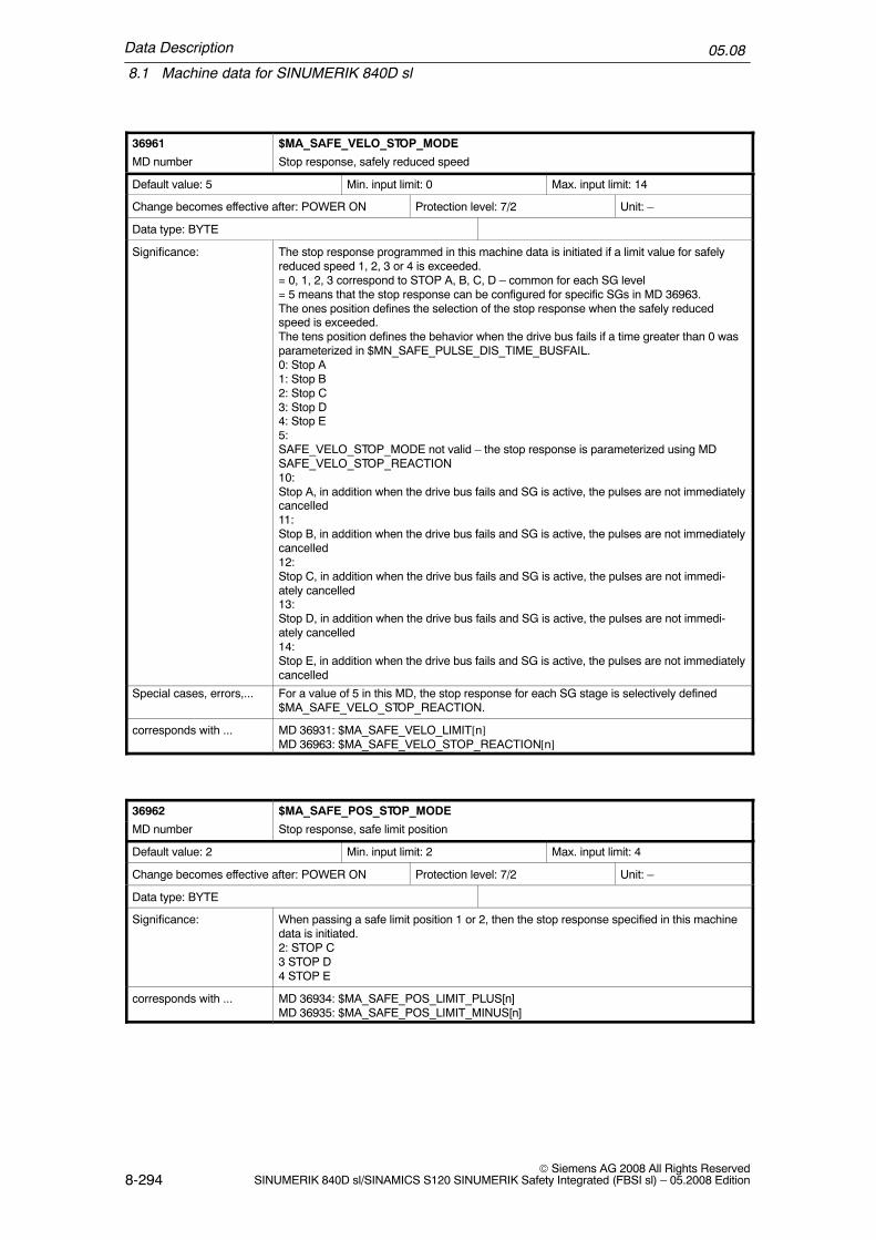
Data Description
8.1 Machine data for SINUMERIK 840D sl
05.08
8-294© Siemens AG 2008 All Rights Reserved
SINUMERIK 840D sl/SINAMICS S120 SINUMERIK Safety Integrated (FBSI sl) – 05.2008 Edition
36961 $MA_SAFE_VELO_STOP_MODE
MD number Stop response, safely reduced speed
Default value: 5 Min. input limit: 0 Max. input limit: 14
Change becomes effective after: POWER ON Protection level: 7/2 Unit: –
Data type: BYTE
Significance: The stop response programmed in this machine data is initiated if a limit value for safelyreduced speed 1, 2, 3 or 4 is exceeded.= 0, 1, 2, 3 correspond to STOP A, B, C, D – common for each SG level= 5 means that the stop response can be configured for specific SGs in MD 36963.The ones position defines the selection of the stop response when the safely reducedspeed is exceeded.The tens position defines the behavior when the drive bus fails if a time greater than 0 wasparameterized in $MN_SAFE_PULSE_DIS_TIME_BUSFAIL.0: Stop A1: Stop B2: Stop C3: Stop D4: Stop E5:SAFE_VELO_STOP_MODE not valid – the stop response is parameterized using MDSAFE_VELO_STOP_REACTION10:Stop A, in addition when the drive bus fails and SG is active, the pulses are not immediatelycancelled11:Stop B, in addition when the drive bus fails and SG is active, the pulses are not immediatelycancelled12:Stop C, in addition when the drive bus fails and SG is active, the pulses are not immedi-ately cancelled13:Stop D, in addition when the drive bus fails and SG is active, the pulses are not immedi-ately cancelled14:Stop E, in addition when the drive bus fails and SG is active, the pulses are not immediatelycancelled
Special cases, errors,... For a value of 5 in this MD, the stop response for each SG stage is selectively defined$MA_SAFE_VELO_STOP_REACTION.
corresponds with ... MD 36931: $MA_SAFE_VELO_LIMIT[n]MD 36963: $MA_SAFE_VELO_STOP_REACTION[n]
36962 $MA_SAFE_POS_STOP_MODE
MD number Stop response, safe limit position
Default value: 2 Min. input limit: 2 Max. input limit: 4
Change becomes effective after: POWER ON Protection level: 7/2 Unit: –
Data type: BYTE
Significance: When passing a safe limit position 1 or 2, then the stop response specified in this machinedata is initiated.2: STOP C3 STOP D4 STOP E
corresponds with ... MD 36934: $MA_SAFE_POS_LIMIT_PLUS[n]MD 36935: $MA_SAFE_POS_LIMIT_MINUS[n]

Data Description
8.1 Machine data for SINUMERIK 840D sl
05.08
8-295© Siemens AG 2008 All Rights ReservedSINUMERIK 840D sl/SINAMICS S120 SINUMERIK Safety Integrated (FBSI sl) – 05.2008 Edition
36963 $MA_SAFE_VELO_STOP_REACTION[n]: 0 ... 3
MD number Stop response, safely reduced speed
Default value: 2 Min. input limit: 0 Max. input limit: 14
Change becomes effective after: POWER ON Protection level: 7/2 Unit: –
Data type: BYTE
Significance: The stop response programmed in this machine data is initiated if a limit value for safelyreduced speed 1, 2, 3 or 4 is exceeded.n = 0, 1, 2, 3 stands for SG1, SG2, SG3, SG4The ones position defines the SG–specific selection of the stop response when the safelyreduced speed is exceeded.The tens position defines the behavior when the drive bus fails on an SG–specific basis if atime greater than 0 was parameterized in $MN_SAFE_PULSE_DIS_TIME_BUSFAIL.Value means:0: Stop A1: Stop B2: Stop C3: Stop D4: Stop E10:Stop A, in addition, when the drive bus fails, the pulses are not immediately cancelled if thisSG stage is active.11:Stop B, in addition, when the drive bus fails, the pulses are not immediately cancelled if thisSG stage is active.12:Stop C, in addition, when the drive bus fails, the pulses are not immediately cancelled if thisSG stage is active.13:Stop D, in addition, when the drive bus fails, the pulses are not immediately cancelled if thisSG stage is active.14:Stop E, in addition, when the drive bus fails, the pulses are not immediately cancelled if thisSG stage is active.
Special cases, errors,... This function is only active when MD 36961 and MD 1361 have the value 5.
corresponds with ... MD 10089: $MA_SAFE_PULSE_DIS_TIME_BUSFAILMD 36961: $MA_SAFE_VELO_STOP_MODE

Data Description
8.1 Machine data for SINUMERIK 840D sl
05.08
8-296© Siemens AG 2008 All Rights Reserved
SINUMERIK 840D sl/SINAMICS S120 SINUMERIK Safety Integrated (FBSI sl) -- 05.2008 Edition
36964 $MA_SAFE_IPO_STOP_GROUP
MD number Grouping, safety IPO response
Default value: 0 Min. input limit: 0 Max. input limit: 1
Change becomes effective after: RESET Protection level: 7/2 Unit: --
Data type: BYTE
Significance: This MD is only effective for Safety Integrated axes/spindles.It influences the channel--wide IPO response distribution of Safety Integrated.0 = default:All other axes/spindles in the channel are notified of the IPO stop response of this axis.1 =For internal stops, the axes and machining spindles, interpolating with the axis involved, arealso additionally influenced via the initiated safety alarms. On the other hand, other axes/spindles in the channel continue to operate without any disturbance.For external stops (without alarm) all of the other axes/spindles remain unaffected by thesafety axis/spindle stop. This allows, for example, the pulses of the spindle to be safelycancelled (using an external Stop A). This means that the spindle can be manually rotatedand the axes can still be safely monitored while it is moving.If, in some machining situations, the other axes/spindles should stop together with thesafety axis/spindle, then the user is responsible in implementing this using PLC orsynchronous action logic combinations.
corresponds with ...
36965 $MA_SAFE_PARK_ALARM_SUPPRESS
MD number Alarm suppression for parking axis
Default value: FALSE Min. input limit: -- Max. input limit: --
Change becomes effective after: POWER ON Protection level: 7/2 Unit: --
Data type: BOOLEAN
Significance: This MD is only effective for Safety Integrated axes/spindles.0: Default:Alarms 27000/A01797 are displayed when selecting parking.1:Alarms 27000/A01797 are not displayed when selecting parking. This is necessary for axesthat are disconnected from one another on the encoder side during the machining process(e.g. dressing axes). Alarms are displayed when parking operation is subsequently dese-lected.
corresponds with ...

Data Description
8.1 Machine data for SINUMERIK 840D sl
05.08
8-297© Siemens AG 2008 All Rights ReservedSINUMERIK 840D sl/SINAMICS S120 SINUMERIK Safety Integrated (FBSI sl) – 05.2008 Edition
36966 $MA_SAFE_BRAKETEST_TORQUE
MD number Holding torque, brake test
Default value: 5.0 Min. input limit: 0.0 Max. input limit: 800.0
Change becomes effective after: POWER ON Protection level: 7/2 Unit: %
Data type: DOUBLE
Significance: This MD specifies the torque or force when testing the mechanical brake system. Thistorque or this force is generated during the test against the closed brake and it is not per-missible that the axis moves.The percentage value entered here refers to drive parameter p2003 of the axis.When selecting the brake test (i.e. with the brake open), if the actual torque is more than85% of the test torque, the brake test is interrupted with Alarm 20095. This therefore en-sures that the motor can hold the axis even if the brake is defective.If the brake test is performed using drive parameter p1532 ($MA_SAFE_BRAKET-EST_CONTROL bit 0 = 0), the required safety margin is increased by twice the differencebetween the actual holding torque and the value in parameter p1532.The corresponding test function is enabled using MD $MA_FIXED_STOP_MODE bit 1.
corresponds with ... MD 36969: $MN_SAFE_BRAKETEST_TORQUE_NORM
Additional references /FBSI/ see Chapter 7.4: ”Safe brake test (SBT)”
36967 $MA_SAFE_BRAKETEST_POS_TOL
MD number Position tolerance, brake test
Default value: 1.0 Min. input limit: – Max. input limit: –
Change becomes effective after: POWER ON Protection level: 7/2 Unit: mm/degr.
Data type: DOUBLE
Significance: Maximum position tolerance when testing the mechanical brake system.If the axis position deviates from the position by more than this tolerance, when the braketest is selected, then the brake test is aborted.The corresponding test function is enabled using MD $MA_FIXED_STOP_MODE bit 1.
corresponds with ...
Additional references /FBSI/ see Chapter 7.4: ”Safe brake test (SBT)”
36968 $MA_SAFE_BRAKETEST_CONTROL
MD number Expanded setting for the brake test
Default value: 0 Min. input limit: 0 Max. input limit: 1
Change becomes effective after: POWER ON Protection level: 7/2 Unit: –
Data type: DWORD
Significance: Expanded settings for the brake test.Bit 0: Select the average value for the torque limiting0:Drive parameter p1532 is used as the average value of the torque limiting.1:The measured torque at the instant in time that the brake test is selected is used as theaverage value of the torque limit.
corresponds with ...
Additional references /FBSI/ see Chapter 7.4: ”Safe brake test (SBT)”

Data Description
8.1 Machine data for SINUMERIK 840D sl
05.08
8-298© Siemens AG 2008 All Rights Reserved
SINUMERIK 840D sl/SINAMICS S120 SINUMERIK Safety Integrated (FBSI sl) – 05.2008 Edition
36969 $MA_SAFE_BRAKETEST_TORQUE_NORM
MD number Reference quantity for the holding torque, brake test
Default value: 0.0 Min. input limit: – Max. input limit: –
Change becomes effective after: POWER ON Protection level: 7/0 Unit: Nm
Data type: DOUBLE
Significance: Setting the reference quantity for torques.All of the torques specified as relative value refer to this reference quantity. This MD in-volves an image of drive parameter p2003.
corresponds with ...
Additional references
Description of the parameterization of the SGE machine data MD 36970 to MD 36978
This machine data involves eight–digit hexadecimal numbers, where each digit hasa different significance that is now explained:
Coding of the input assignment
is mm xx nn Permissi-ble values
Explanation
i Inversion 0, 8 0: No inversion8: Inversion before processing
s Segment No. 0, 4 4: Internal image in the systemmemory (system variable)
mm Module No. 01–02 01: Addressing the internal SPLinterface $A_OUTSI
02: Addressing the external SPLinterface (only for input signals,$A_INSE)
xx Sub–module No.
01–02 Index of the system variable word(each 32 bit)
nn I/O No. 01–20 Bit number in the system variableword $A_OUTSID[xx],$A_INSED[xx]
If several output signals are set, then the signal involved is first inverted. The (insome cases inverted) output signals are then AND’ed and the result is output atthe terminal.

Data Description
8.1 Machine data for SINUMERIK 840D sl
05.08
8-299© Siemens AG 2008 All Rights ReservedSINUMERIK 840D sl/SINAMICS S120 SINUMERIK Safety Integrated (FBSI sl) – 05.2008 Edition
Note
The maximum input value for all axial NCK_SGE configured machine data is84020220An incorrect entry will be detected the next time the system boots and flaggedusing Alarm 27033.
36970 $MA_SAFE_SVSS_DISABLE_INPUT
MD number Input assignment, SBH/SG deselection
Default value: 0 Min. input limit: – Max. input limit: –
Change becomes effective after: POWER ON Protection level: 7/2 Unit: –
Data type: DWORD
Significance:
Configuration:
This machine data defines the NCK input to select/deselect the SBH and SG functionsSignal means= 0, SG or SBH is selected= 1, SG and SBH are deselectedConfiguration: Refer to the coding of the input assignment
Special cases, errors,... � Input value of 0 means: There is no assignment, the input remains fixed at 0, SG andSBH cannot be deselected
� Input value of 80 00 00 00 means: There is no assignment, the input remains fixed at 1� If MD bit 31 is set, then the signal is processed inverted (i = 8).
corresponds with ...
References:
36971 $MA_SAFE_SS_DISABLE_INPUT
MD number Input assignment, SBH deselection
Default value: 0 Min. input limit: – Max. input limit: –
Change becomes effective after: POWER ON Protection level: 7/2 Unit: –
Data type: DWORD
Significance: Assignment of the NCK input to deselect the safe operating stop function.Configuration: Refer to the coding of the input assignmentAssignment of the terminal signal level to the safe functions if safely reduced speed or safeoperating stop has been activated.Signal means= 0, safe operating stop is selected= 1, safe operating stop is deselected (only if STOP C, D or E has not been activated byother functions)
Special cases, errors,... � If MD bit 31 is set, then the signal is processed inverted (i = 8).� This input is of no significance if SG and SBH have been deselected (refer to
$MA_SAFE_SVSS_DISABLE_INPUT).
corresponds with ... MD 36970: $MA_SAFE_SVSS_DISABLE_INPUT

Data Description
8.1 Machine data for SINUMERIK 840D sl
05.08
8-300© Siemens AG 2008 All Rights Reserved
SINUMERIK 840D sl/SINAMICS S120 SINUMERIK Safety Integrated (FBSI sl) – 05.2008 Edition
36972 $MA_SAFE_VELO_SELECT_INPUT[n]: 0 ... 1
MD number Input assignment, SG selection
Default value: 0 Min. input limit: – Max. input limit: –
Change becomes effective after: POWER ON Protection level: 7/2 Unit: –
Data type: DWORD
Significance: This machine data defines the two inputs to select SG1, SG2, SG3 or SG4.Configuration: Refer to the coding of the input assignmentn = 1, 0 stand for bit 1, 0 to select from SG1 to SG4Assignment of the input bits to the safely reduced speeds:Bit 1 Bit 0 Selected SG0 0 SG10 1 SG21 0 SG31 1 SG4
Special cases, errors,... If the MD bits 31 are set, then the signal is processed inverted (i = 8).
corresponds with ... MD 36970: $MA_SAFE_SVSS_DISABLE_INPUT
36973 $MA_SAFE_POS_SELECT_INPUT
MD number Input assignment, SE selection
Default value: 0 Min. input limit: – Max. input limit: –
Change becomes effective after: POWER ON Protection level: 7/2 Unit: –
Data type: DWORD
Significance: This machine data defines the input to select the safe limit position 1 or 2.Configuration: Refer to the coding of the input assignmentSignal means= 0, SE1 is active= 1, SE2 is active
Special cases, errors,... If MD bit 31 is set, then the signal is processed inverted (i = 8).
corresponds with ... MD 36970: $MA_SAFE_SVSS_DISABLE_INPUT
36974 $MA_SAFE_GEAR_SELECT_INPUT[n]: 0 ... 2
MD number Input assignment, gearbox ratio selection
Default value: 0 Min. input limit: – Max. input limit: –
Change becomes effective after: POWER ON Protection level: 7/2 Unit: –
Data type: DWORD
Significance: Assignment of the input terminals for selecting the gear ratio (gear stage).Configuration: Refer to the coding of the input assignmentn= 2, 1, 0 stand for bit 2, 1, 0 to select gearbox stages 1 to 8Bit 2 Bit 1 Bit 0 active gearbox stage0 0 0 Stage 10 0 1 Stage 20 1 0 Stage 3... ... ... ...1 1 1 Stage 8
Special cases, errors,... If the MD bits 31 are set, then the signal is processed inverted (i = 8).
corresponds with ... MD 36970: $MA_SAFE_SVSS_DISABLE_INPUT

Data Description
8.1 Machine data for SINUMERIK 840D sl
05.08
8-301© Siemens AG 2008 All Rights ReservedSINUMERIK 840D sl/SINAMICS S120 SINUMERIK Safety Integrated (FBSI sl) – 05.2008 Edition
36977 $MA_SAFE_EXT_STOP_INPUT[n]: 0 ... 3
MD number Input assignment, external brake request
Default value: 0, 0, 0, 0 Min. input limit: – Max. input limit: –
Change becomes effective after: POWER ON Protection level: 7/2 Unit: –
Data type: DWORD
Significance: This data defines the NCK inputs to select/deselect the external brake requests.n = 0, 1, 2, 3 stands for various braking typesn = 0: Assignment for ”deselect external STOP A” (SH, pulse cancellation)n = 1: Assignment for ”deselect external STOP C” (braking at the current limit)n = 2: Assignment for ”deselect external STOP D” (braking along a path)n = 3: Assignment for ”deselect external STOP E” (ESR, braking along a path)
Special cases, errors,... If the MD bits 31 are set, then the signal is processed inverted (i = 8). The signal ”deselectexternal STOP A” can not be parameterized inverted. In the case of an error, a parameter-izing error is signaled
corresponds with ... MD 36970: $MA_SAFE_SVSS_DISABLE_INPUT
Additional references
36978 $MA_SAFE_OVR_INPUT[n]: 0 ... 3
MD number Input assignment, SG override
Default value: 0, 0, 0, 0 Min. input limit: – Max. input limit: –
Change becomes effective after: POWER ON Protection level: 7/2 Unit: –
Data type: DWORD
Significance: Assigns the NCK inputs for the correction of the limit value of the safely reduced speeds 2and 4.Configuration: Refer to the coding of the input assignmentn = 3, 2, 1, 0 stand for correction selection bits 3, 2, 1, 0Assigns the input bits to the SG correction values:Bit 3 Bit 2 Bit 1 Bit 00 0 0 0 Correction 0 is selected0 0 0 1 Correction 1 is selectedto1 1 1 1 Correction 15 is selectedThe correction factor itself (percentage) is defined using the following machine data:MD 36932: $MA_SAFE_VELO_OVR_FACTOR[n]
Special cases, errors,... – The function ”correction, safely reduced speed” is enabled using MD 36901:$MA_SAFE_FUNCTION_ENABLE, bit 5.
– If the MD bits 31 are set, then the signal is processed inverted (i = 8).
corresponds with ... MD 36932: $MA_SAFE_VELO_OVR_FACTOR[n]
Additional references /FBSI/ see Chapter 6.5.4: ”Override for safely reduced speed”, refer to MD 36970:$MA_SAFE_SVSS_DISABLE_INPUT

Data Description
8.1 Machine data for SINUMERIK 840D sl
05.08
8-302© Siemens AG 2008 All Rights Reserved
SINUMERIK 840D sl/SINAMICS S120 SINUMERIK Safety Integrated (FBSI sl) – 05.2008 Edition
Description of the parameterization of the SGA machine data MD 36980 to MD 36990
Coding of the output assignment
is mm xx nn Permissi-ble values
Explanation
i Inversion 0, 8 0: No inversion8: Inversion before processing
s Segment No. 0, 4 4: Internal image in the systemmemory (system variable)
mm Module No. 01 01: Addressing the internal SPLinterface $A_INSI
xx Sub–module No.
01–02 Index of the system variable word(each 32 bit)
nn I/O No. 01–20 Bit number in the system variableword $A_INSID[xx]
Note
The maximum input value for all axial NCK_SGA configuring machine data is84010220An incorrect entry will be detected the next time the system boots and flaggedusing Alarm 27033.

Data Description
8.1 Machine data for SINUMERIK 840D sl
05.08
8-303© Siemens AG 2008 All Rights ReservedSINUMERIK 840D sl/SINAMICS S120 SINUMERIK Safety Integrated (FBSI sl) – 05.2008 Edition
36980 $MA_SAFE_SVSS_STATUS_OUTPUT
MD number Output assignment, SBH/SG active
Default value: 0 Min. input limit: – Max. input limit: –
Change becomes effective after: POWER ON Protection level: 7/2 Unit: –
Data type: DWORD
Significance: Assigns the output to signal the status of the functions safely reduced speed and safe oper-ating stop.Signal means:= 0, SG and SBH are not active= 1, SG or SBH is active
Special cases, errors,... – Input value of 0 means: There is no assignment, the output remains unaffected– Input value of 80 00 00 00 means: There is no assignment, the output remains fixed
at 1– If a single output signal is connected to a terminal, the following applies: If MD bit 31 is
set, then the signal is processed inverted (i = 8).– If several output signals are connected to the same terminal, the following applies: If
MD bit 31 is set (i = 8), then the relevant signal is initially inverted. The (in some casesinverted) output signals are then AND’ed and the result is output at the terminal.
corresponds with ...
Additional references Refer to MD 36970: $MA_SAFE_SVSS_DISABLE_INPUT
36981 $MA_SAFE_SS_STATUS_OUTPUT
MD number Output assignment for SBH active
Default value: 0 Min. input limit: – Max. input limit: –
Change becomes effective after: POWER ON Protection level: 7/2 Unit: –
Data type: DWORD
Significance: This machine data defines the output or the system variable for the ”SBH active” signal.Configuration: Refer to the coding of the output assignmentSignal means= 0, SBH is not active= 1, SBH is active
Special cases, errors,... If MD bit 31 is set, then the signal is processed inverted.
Additional references Refer to MD 36980: $MA_SAFE_SVSS_DISABLE_OUTPUT

Data Description
8.1 Machine data for SINUMERIK 840D sl
05.08
8-304© Siemens AG 2008 All Rights Reserved
SINUMERIK 840D sl/SINAMICS S120 SINUMERIK Safety Integrated (FBSI sl) – 05.2008 Edition
36982 $MA_SAFE_VELO_STATUS_OUTPUT[n]: 0 ... 1
MD number Output assignment active SG selection
Default value: 0 Min. input limit: – Max. input limit: –
Change becomes effective after: POWER ON Protection level: 7/2 Unit: –
Data type: DWORD
Significance: This machine data defines the outputs or the system variables for the signals ”SG active bit0” and ”SG active bit 1”.Configuration: Refer to the coding of the output assignmentn = 1, 0 stands for SG active, bits 1, 0SG activeBit 1 Bit 0 means= 0 = 0 SG1 active, if SBH/SG is active and SBH is not active
SBH active, if SBH/SG are active and SBH is active= 1 = 0 SG2 active= 0 = 1 SG3 active= 1 = 1 SG4 active
Special cases, errors,... If MD bit 31 is set, then the signal is processed inverted.
Additional references Refer to MD 36980: $MA_SAFE_SVSS_DISABLE_OUTPUT
36985 $MA_SAFE_VELO_X_STATUS_OUTPUT
MD number Output assignment for n < nx
Default value: 0 Min. input limit: – Max. input limit:
Change becomes effective after: POWER ON Protection level: 7/2 Unit:
Data type: DWORD
Significance: This machine data defines the output or the system variable for the signal ”n < nx”.Configuration: Refer to the coding of the output assignmentSignal means= 0, actual speed is higher than the limit speed in $MA_SAFE_VELO_X= 1, actual speed is lower or equal to the limit speed
Special cases, errors,... If MD bit 31 is set, then the signal is processed inverted.
corresponds with ... MD 36946: $MA_SAFE_VELO_X
Additional references Refer to MD 36980: $MA_SAFE_SVSS_DISABLE_OUTPUT
36987 $MA_SAFE_REFP_STATUS_OUTPUT
MD number Output assignment, axis safely referenced
Default value: 0 Min. input limit: 0 Max. input limit: –
Change becomes effective after: POWER ON Protection level: 7/2 Unit: –
Data type: DWORD
Significance: This machine data specifies the output for the ”axis safely referenced” signal.Signal= 0Axis is not safely referenced (i.e. the safe limit position monitoring is inactive!)= 1Axis is safely referenced
Special cases, errors,... If MD bit 31 is set, then the signal is processed inverted.
Additional references Refer to MD 36980: $MA_SAFE_SVSS_DISABLE_OUTPUT

Data Description
8.1 Machine data for SINUMERIK 840D sl
05.08
8-305© Siemens AG 2008 All Rights ReservedSINUMERIK 840D sl/SINAMICS S120 SINUMERIK Safety Integrated (FBSI sl) – 05.2008 Edition
36988 $MA_SAFE_CAM_PLUS_OUTPUT[n]: 0 ... 3
MD number Output assignment, SN1+ to SN4+
Default value: 0, 0, 0, 0 Min. input limit: – Max. input limit: –
Change becomes effective after: POWER ON Protection level: 7/2 Unit: –
Data type: DWORD
Significance: This machine data specifies the outputs for the cam signals SN1+ to SN4+.n = 0, 1, 2, 3 stands for the assignment of plus cams SN1+, SN2+, SN3+, SN4+Signal means= 0Axis is located to the left of the cam (actual value < cam position)= 1Axis is located to the right of the cam (actual value > cam position)
Special cases, errors,... If MD bit 31 is set, then the signal is processed inverted.
Additional references Refer to MD 36980: $MA_SAFE_SVSS_DISABLE_OUTPUT(/FBSI/ see Chapter 6.8: Safe software cams, output assignment)
36989 $MA_SAFE_CAM_MINUS_OUTPUT[n]: 0 ... 3
MD number Output assignment, SN1– to SN4–
Default value: 0 Min. input limit: – Max. input limit: –
Change becomes effective after: POWER ON Protection level: 7/2 Unit:
Data type: DWORD
Significance: This machine data defines the outputs for the minus cams SN1– to SN4–.= 0, 1, 2, 3 corresponds to the assignment for minus cams SN1–, SN2–, SN3–, SN4–Signal means= 0Axis is located to the left of the cam (actual value < cam position)= 1Axis is located to the right of the cam (actual value > cam position)
Special cases, errors,... – In order to generate a cam signal to identify the range, a cam must be negated andmust be parameterized with another cam at the same output.
Additional references Refer to MD 36980: $MA_SAFE_SVSS_DISABLE_OUTPUT(/FBSI/ see Chapter 6.8: Safe software cams, output assignment)
36990 $MA_SAFE_ ACT_STOP_OUTPUT[n]: 0...3
MD number Output assignment of the active stop
Default value: 0 Min. input limit: – Max. input limit: –
Change becomes effective after: POWER ON Protection level: 7/2 Unit: –
Data type: DWORD
Significance: Assignment of the output terminals to display the stops that are presently active.Index = 0: Assignment for ”STOP A/B is active”Index = 1: Assignment for ”STOP C is active”Index = 2: Assignment for ”STOP D is active”Index = 3: Assignment for ”STOP E is active”
Special cases, errors,...
corresponds with ...
Additional references Refer to MD 36980: $MA_SAFE_SVSS_DISABLE_OUTPUT

Data Description
8.1 Machine data for SINUMERIK 840D sl
05.08
8-306© Siemens AG 2008 All Rights Reserved
SINUMERIK 840D sl/SINAMICS S120 SINUMERIK Safety Integrated (FBSI sl) – 05.2008 Edition
36992 $MA_SAFE_CROSSCHECK_CYCLE
MD number Displays the axial crosswise comparison clock cycle
Default value: 0.0 Min. input limit: 0 Max. input limit: –
Change becomes effective after: POWER ON Protection level: 7/0 Unit: s
Data type: DOUBLE
Significance: Safety system, display date: Indicates the effective axial comparison clock cycle inseconds.The clock cycle is obtained from INFO_SAFETY_CYCLE_TIME and the number of data tobe compared crosswise.The axial value displayed depends on the associated drive module, as the length of thecrosswise comparison list differs between performance–1/Standard–2 and Performance–2modules.
Special cases, errors,...
36993 $MA_SAFE_CONFIG_CHANGE_DATE[n]: n = 0...7
MD number Date/time of the last change SI–NCK–MD
Default value: ”” Min. input limit: – Max. input limit: –
Change becomes effective after: POWER ON Protection level: 7/0 Unit: –
Data type: STRING
Significance: Safety system, display date: Date and time of the last configuration change of safety–related NCK machine data. Changes made to the machine data that are calculated into theaxial checksums SAFE_ACT_CHECKSUM are recorded.
Special cases, errors,...
36994 $MA_SAFE_PREV_CONFIG[n]: n = 0...8
MD number Data, previous safety configuration
Default value: 0 Min. input limit: – Max. input limit: FFFFFFFF
Change becomes effective after: POWER ON Protection level: 0/0 Unit: –
Data type: DWORD
Significance: Buffer memory to save previous safety configuration dataIndex[0]: Status flag bit of the change historyIndex[1]: Previous value, function enableIndex[2]: Previous value, reference checksumIndex[3]: Last value, function enable before loading standard dataIndex[4]: Last value, reference checksum before loading standard dataIndex[5]: Previous value, reference checksum[1]Index[6]: Last value, reference checksum [1] before loading standard dataIndex[7]: Previous value, reference checksum[2]Index[8]: Last value, reference checksum [2] before loading standard data
Special cases, errors,...

Data Description
8.1 Machine data for SINUMERIK 840D sl
05.08
8-307© Siemens AG 2008 All Rights ReservedSINUMERIK 840D sl/SINAMICS S120 SINUMERIK Safety Integrated (FBSI sl) – 05.2008 Edition
36995 $MA_SAFE_STANDSTILL_POS
MD number Standstill position
Default value: 0 Min. input limit: – Max. input limit: –
Change becomes effective after: POWER ON Protection level: 0/0 Unit: –
Data type: DWORD
Significance: The position at which the axis has currently stopped is displayed in this MD.To be able to perform a plausibility check on the axis referencing when the control systemis powered–up the next time, the current axis position is permanently saved (in a non–vola-tile fashion) when the following events take place:– When safe operating stop (SBH) is selected– Cyclically when SE/SN is active
Special cases, errors,... Any manual changes to the MD are detected the next time that the control is powered–up(plausibility check). A new user agreement is required after referencing.
36997 $MA_SAFE_ACKN
MD number User acknowledgement
Default value: 0 Min. input limit: – Max. input limit: –
Change becomes effective after: POWER ON Protection level: 7/2 Unit: –
Data type: DWORD
Significance: The status of the user agreement is displayed in this machine data.The user can confirm or cancel his ”user agreement” using an appropriate screen.If it is internally detected in the software that the reference to the machine has been lost,then it is automatically cancelled (e.g. when changing over gear ratios or when referencing,the plausibility check when comparing with the saved stop position fails).
Special cases, errors,... Any manual changes to the MD are detected the next time that the control is powered–up(plausibility check). A new user agreement is required after referencing.
36998 $MA_SAFE_ACT_CHECKSUM[0,1,2]
MD number Actual checksum
Default value: 0, 0, 0 Min. input limit: – Max. input limit: –
Change becomes effective after: POWER ON Protection level: 7/0 Unit: –
Data type: DWORD
Significance: The actual checksum – calculated after power on or a reset – over the current values ofsafety–related machine data is entered here.Assigning the indices:Index 0: Axial monitoring functions and global NC machine data for Safety IntegratedIndex 1: HW component IDsIndex 2: PROFIsafe parameters from the S7 configuring
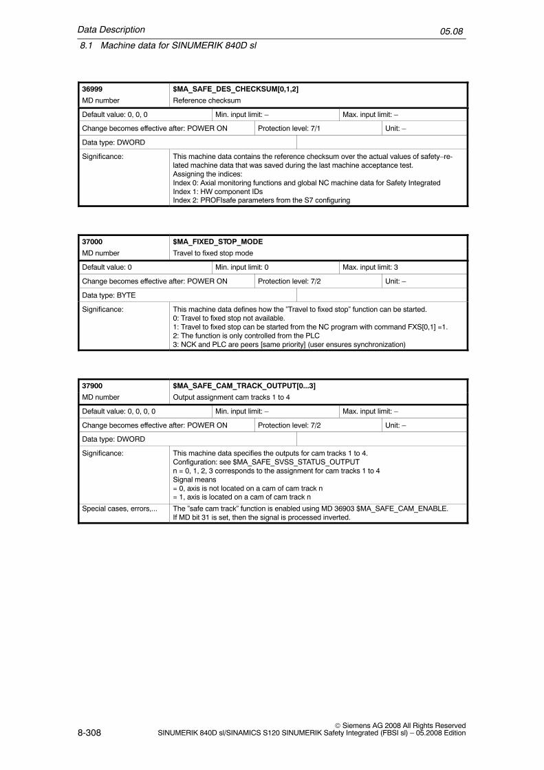
Data Description
8.1 Machine data for SINUMERIK 840D sl
05.08
8-308© Siemens AG 2008 All Rights Reserved
SINUMERIK 840D sl/SINAMICS S120 SINUMERIK Safety Integrated (FBSI sl) – 05.2008 Edition
36999 $MA_SAFE_DES_CHECKSUM[0,1,2]
MD number Reference checksum
Default value: 0, 0, 0 Min. input limit: – Max. input limit: –
Change becomes effective after: POWER ON Protection level: 7/1 Unit: –
Data type: DWORD
Significance: This machine data contains the reference checksum over the actual values of safety–re-lated machine data that was saved during the last machine acceptance test.Assigning the indices:Index 0: Axial monitoring functions and global NC machine data for Safety IntegratedIndex 1: HW component IDsIndex 2: PROFIsafe parameters from the S7 configuring
37000 $MA_FIXED_STOP_MODE
MD number Travel to fixed stop mode
Default value: 0 Min. input limit: 0 Max. input limit: 3
Change becomes effective after: POWER ON Protection level: 7/2 Unit: –
Data type: BYTE
Significance: This machine data defines how the ”Travel to fixed stop” function can be started.0: Travel to fixed stop not available.1: Travel to fixed stop can be started from the NC program with command FXS[0,1] =1.2: The function is only controlled from the PLC3: NCK and PLC are peers [same priority] (user ensures synchronization)
37900 $MA_SAFE_CAM_TRACK_OUTPUT[0...3]
MD number Output assignment cam tracks 1 to 4
Default value: 0, 0, 0, 0 Min. input limit: – Max. input limit: –
Change becomes effective after: POWER ON Protection level: 7/2 Unit: –
Data type: DWORD
Significance: This machine data specifies the outputs for cam tracks 1 to 4.Configuration: see $MA_SAFE_SVSS_STATUS_OUTPUTn = 0, 1, 2, 3 corresponds to the assignment for cam tracks 1 to 4Signal means= 0, axis is not located on a cam of cam track n= 1, axis is located on a cam of cam track n
Special cases, errors,... The ”safe cam track” function is enabled using MD 36903 $MA_SAFE_CAM_ENABLE.If MD bit 31 is set, then the signal is processed inverted.

Data Description
8.1 Machine data for SINUMERIK 840D sl
05.08
8-309© Siemens AG 2008 All Rights ReservedSINUMERIK 840D sl/SINAMICS S120 SINUMERIK Safety Integrated (FBSI sl) – 05.2008 Edition
37901 $MA_SAFE_CAM_RANGE_OUTPUT_1[0...3]
MD number Output assignment, cam range for cam track 1
Default value: 0, 0, 0, 0 Min. input limit: – Max. input limit: –
Change becomes effective after: POWER ON Protection level: 7/2 Unit: –
Data type: DWORD
Significance: This machine data specifies the outputs for the cam range of cam track 1.Configuration: see $MA_SAFE_SVSS_STATUS_OUTPUTn = 0, 1, 2, 3 corresponds to the 4 bits to specify the range on cam track 1Bit 3 Bit 2 Bit 1 Bit 00 0 0 0 Cam range 0 is active0 0 0 1 Cam range 1 is activeup to ...1 1 1 1 Cam range 15 is activeThe cam range is defined using the following machine data:MD 36938: $MA_SAFE_CAM_TRACK_ASSIGN[n]Signal means= 0...14, axis is located in the range of the cam that was assigned to range ID 0...14 oncam track 1.= 15 axis is located in the range to the right of the outermost cam of cam track 1
Special cases, errors,... The ”safe cam track” function is enabled using MD 36903 $MA_SAFE_CAM_ENABLE.If the MD bits 31 are set, then the signal is processed inverted.If not all of the 4 bits are assigned, then under certain circumstances, it cannot be uniquelyand clearly identified as to which cam range is active.
corresponds with ... MD 37900: $MA_SAFE_CAM_TRACK_OUTPUT
37902 $MA_SAFE_CAM_RANGE_OUTPUT_2[0...3]
MD number Output assignment, cam range for cam track 2
Default value: 0, 0, 0, 0 Min. input limit: – Max. input limit: –
Change becomes effective after: POWER ON Protection level: 7/2 Unit: –
Data type: DWORD
Significance: This machine data specifies the outputs for the cam range of cam track 2.Configuration: see $MA_SAFE_SVSS_STATUS_OUTPUTn = 0, 1, 2, 3 corresponds to the 4 bits to specify the range on cam track 2Bit 3 Bit 2 Bit 1 Bit 00 0 0 0 Cam range 0 is active0 0 0 1 Cam range 1 is activeup to ...1 1 1 1 Cam range 15 is activeThe cam range is defined using the following machine data:MD 36938: $MA_SAFE_CAM_TRACK_ASSIGN[n]Signal means= 0...14, axis is located in the range of the cam that was assigned to range ID 0...14 oncam track 2.= 15 axis is located in the range to the right of the outermost cam of cam track 2
Special cases, errors,... The ”safe cam track” function is enabled using MD 36903 $MA_SAFE_CAM_ENABLE.If the MD bits 31 are set, then the signal is processed inverted.If not all of the 4 bits are assigned, then under certain circumstances, it cannot be uniquelyand clearly identified as to which cam range is active.
corresponds with ... MD 37900: $MA_SAFE_CAM_TRACK_OUTPUT

Data Description
8.1 Machine data for SINUMERIK 840D sl
05.08
8-310© Siemens AG 2008 All Rights Reserved
SINUMERIK 840D sl/SINAMICS S120 SINUMERIK Safety Integrated (FBSI sl) – 05.2008 Edition
37903 $MA_SAFE_CAM_RANGE_OUTPUT_3[0...3]
MD number Output assignment, cam range for cam track 3
Default value: 0, 0, 0, 0 Min. input limit: – Max. input limit: –
Change becomes effective after: POWER ON Protection level: 7/2 Unit: –
Data type: DWORD
Significance: This machine data specifies the outputs for the cam range of cam track 3.Configuration: see $MA_SAFE_SVSS_STATUS_OUTPUTn = 0, 1, 2, 3 corresponds to the 4 bits to specify the range on cam track 3Bit 3 Bit 2 Bit 1 Bit 00 0 0 0 Cam range 0 is active0 0 0 1 Cam range 1 is activeup to ...1 1 1 1 Cam range 15 is activeThe cam range is defined using the following machine data:MD 36938: $MA_SAFE_CAM_TRACK_ASSIGN[n]Signal means= 0...14, axis is located in the range of the cam that was assigned to range ID 0...14 oncam track 3.= 15 axis is located in the range to the right of the outermost cam of cam track 3
Special cases, errors,... The ”safe cam track” function is enabled using MD 36903 $MA_SAFE_CAM_ENABLE.If the MD bits 31 are set, then the signal is processed inverted.If not all of the 4 bits are assigned, then under certain circumstances, it cannot be uniquelyand clearly identified as to which cam range is active.
corresponds with ... MD 37900: $MA_SAFE_CAM_TRACK_OUTPUT
37904 $MA_SAFE_CAM_RANGE_OUTPUT_4[0...3]
MD number Output assignment, cam range for cam track 4
Default value: 0, 0, 0, 0 Min. input limit: – Max. input limit: –
Change becomes effective after: POWER ON Protection level: 7/2 Unit: –
Data type: DWORD
Significance: This machine data specifies the outputs for the cam range of cam track 4.Configuration: see $MA_SAFE_SVSS_STATUS_OUTPUTn = 0, 1, 2, 3 corresponds to the 4 bits to specify the range on cam track 4Bit 3 Bit 2 Bit 1 Bit 00 0 0 0 Cam range 0 is active0 0 0 1 Cam range 1 is activeup to ...1 1 1 1 Cam range 15 is activeThe cam range is defined using the following machine data:MD 36938: $MA_SAFE_CAM_TRACK_ASSIGN[n]Signal means= 0...14, axis is located in the range of the cam that was assigned to range ID 0...14 oncam track 4.= 15 axis is located in the range to the right of the outermost cam of cam track 4
Special cases, errors,... The ”safe cam track” function is enabled using MD 36903 $MA_SAFE_CAM_ENABLE.If the MD bits 31 are set, then the signal is processed inverted.If not all of the 4 bits are assigned, then under certain circumstances, it cannot be uniquelyand clearly identified as to which cam range is active.
corresponds with ... MD 37900: $MA_SAFE_CAM_TRACK_OUTPUT
37906 $MA_SAFE_CAM_RANGE_BIN_OUTPUT_1[0...14]
MD number Output assignment, cam range bit for cam track 1
Default value: 0, 0, 0, 0 Min. input limit: 0 Max. input limit: –

Data Description
8.1 Machine data for SINUMERIK 840D sl
05.08
8-311© Siemens AG 2008 All Rights ReservedSINUMERIK 840D sl/SINAMICS S120 SINUMERIK Safety Integrated (FBSI sl) – 05.2008 Edition
37906 $MA_SAFE_CAM_RANGE_BIN_OUTPUT_1[0...14]
MD number Output assignment, cam range bit for cam track 1
Change becomes effective after: POWER ON Protection level: 7/2 Unit: –
Data type: DWORD
Significance: This machine data specifies the outputs for the cam range bits of cam track 1.Configuration: see $MA_SAFE_SVSS_STATUS_OUTPUTField index n corresponds to the parameterizable cam range numbers on cam track 1.
The cam range number is defined using the following machine data:MD 36938: $MA_SAFE_CAM_TRACK_ASSIGN[0...29]
Signal means= 0, axis is not located on the cam with cam range number n= 1, axis is located on the cam with cam range number nExample:The signal that is addressed using field index 5 goes to 1 if the axis is located at the camthat is assigned to cam track 1 by parameterizing the cam range number 5.
Special cases, errors,... The ”safe cam track” function is enabled using MD 36903 $MA_SAFE_CAM_ENABLE.If the MD bits 31 are set, then the signal is processed inverted.If the cam range number n is not parameterized on cam track 1 then the signal of field indexn can never go to 1. The output MD with field index n must in this case not be parameter-ized.
37907 $MA_SAFE_CAM_RANGE_BIN_OUTPUT_2[0...14]
MD number Output assignment, cam range bit for cam track 2
Default value: 0, 0, 0, 0 Min. input limit: 0 Max. input limit: –
Change becomes effective after: POWER ON Protection level: 7/2 Unit: –
Data type: DWORD
Significance: This machine data specifies the outputs for the cam range bits of cam track 2.Configuration: see $MA_SAFE_SVSS_STATUS_OUTPUTField index n corresponds to the parameterizable cam range numbers on cam track 2.
The cam range number is defined using the following machine data:MD 36938: $MA_SAFE_CAM_TRACK_ASSIGN[0...29]
Signal means= 0, axis is not located on the cam with cam range number n= 1, axis is located on the cam with cam range number nExample:The signal that is addressed using field index 5 goes to 1 if the axis is located at the camthat is assigned to cam track 2 by parameterizing the cam range number 5.
Special cases, errors,... The ”safe cam track” function is enabled using MD 36903 $MA_SAFE_CAM_ENABLE.If the MD bits 31 are set, then the signal is processed inverted.If the cam range number n is not parameterized on cam track 2 then the signal of field indexn can never go to 1. The output MD with field index n must in this case not be parameter-ized.

Data Description
8.1 Machine data for SINUMERIK 840D sl
05.08
8-312© Siemens AG 2008 All Rights Reserved
SINUMERIK 840D sl/SINAMICS S120 SINUMERIK Safety Integrated (FBSI sl) – 05.2008 Edition
37908 $MA_SAFE_CAM_RANGE_BIN_OUTPUT_3[0...14]
MD number Output assignment, cam range bit for cam track 3
Default value: 0, 0, 0, 0 Min. input limit: – Max. input limit: –
Change becomes effective after: POWER ON Protection level: 7/2 Unit: –
Data type: DWORD
Significance: This machine data specifies the outputs for the cam range bits of cam track 3.Configuration: see $MA_SAFE_SVSS_STATUS_OUTPUTField index n corresponds to the parameterizable cam range numbers on cam track 3.
The cam range number is defined using the following machine data:MD 36938: $MA_SAFE_CAM_TRACK_ASSIGN[0...29]
Signal means= 0, axis is not located on the cam with cam range number n= 1, axis is located on the cam with cam range number nExample:The signal that is addressed using field index 5 goes to 1 if the axis is located at the camthat is assigned to cam track 3 by parameterizing the cam range number 5.
Special cases, errors,... The ”safe cam track” function is enabled using MD 36903 $MA_SAFE_CAM_ENABLE.If the MD bits 31 are set, then the signal is processed inverted.If the cam range number n is not parameterized on cam track 3 then the signal of field indexn can never go to 1. The output MD with field index n must in this case not be parameter-ized.
37909 $MA_SAFE_CAM_RANGE_BIN_OUTPUT_4[0...14]
MD number Output assignment, cam range bit for cam track 3
Default value: 0, 0, 0, 0 Min. input limit: – Max. input limit: –
Change becomes effective after: POWER ON Protection level: 7/2 Unit: –
Data type: DWORD
Significance: This machine data specifies the outputs for the cam range bits of cam track 4.Configuration: see $MA_SAFE_SVSS_STATUS_OUTPUTField index n corresponds to the parameterizable cam range numbers on cam track 4.
The cam range number is defined using the following machine data:MD 36938: $MA_SAFE_CAM_TRACK_ASSIGN[0...29]
Signal means= 0, axis is not located on the cam with cam range number n= 1, axis is located on the cam with cam range number nExample:The signal that is addressed using field index 5 goes to 1 if the axis is located at the camthat is assigned to cam track 4 by parameterizing the cam range number 5.
Special cases, errors,... The ”safe cam track” function is enabled using MD 36903 $MA_SAFE_CAM_ENABLE.If the MD bits 31 are set, then the signal is processed inverted.If the cam range number n is not parameterized on cam track 4 then the signal of field indexn can never go to 1. The output MD with field index n must in this case not be parameter-ized.
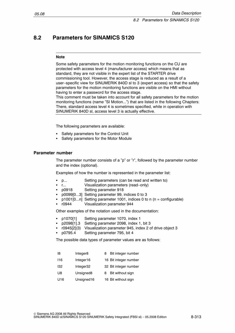
Data Description
8.2 Parameters for SINAMICS S120
05.08
8-313© Siemens AG 2008 All Rights ReservedSINUMERIK 840D sl/SINAMICS S120 SINUMERIK Safety Integrated (FBSI sl) – 05.2008 Edition
8.2 Parameters for SINAMICS S120
Note
Some safety parameters for the motion monitoring functions on the CU areprotected with access level 4 (manufacturer access) which means that asstandard, they are not visible in the expert list of the STARTER drivecommissioning tool. However, the access stage is reduced as a result of auser–specific view for SINUMERIK 840D sl to 3 (expert access) so that the safetyparameters for the motion monitoring functions are visible on the HMI withouthaving to enter a password for the access stage.This comment must be taken into account for all safety parameters for the motionmonitoring functions (name ”SI Motion...”) that are listed in the following Chapters:There, standard access level 4 is sometimes specified, while in operation withSINUMERIK 840D sl, access level 3 is actually effective.
The following parameters are available:
� Safety parameters for the Control Unit� Safety parameters for the Motor Module
Parameter number
The parameter number consists of a ”p” or ”r”, followed by the parameter numberand the index (optional).
Examples of how the number is represented in the parameter list:
� p... Setting parameters (can be read and written to)� r... Visualization parameters (read–only)� p0918 Setting parameter 918� p0099[0...3] Setting parameter 99, indices 0 to 3� p1001[0...n] Setting parameter 1001, indices 0 to n (n = configurable)� r0944 Visualization parameter 944
Other examples of the notation used in the documentation:
� p1070[1] Setting parameter 1070, index 1� p2098[1].3 Setting parameter 2098, index 1, bit 3� r0945[2](3) Visualization parameter 945, index 2 of drive object 3� p0795.4 Setting parameter 795, bit 4
The possible data types of parameter values are as follows:
I8 Integer8 8 Bit integer number
I16 Integer16 16 Bit integer number
I32 Integer32 32 Bit integer number
U8 Unsigned8 8 Bit without sign
U16 Unsigned16 16 Bit without sign
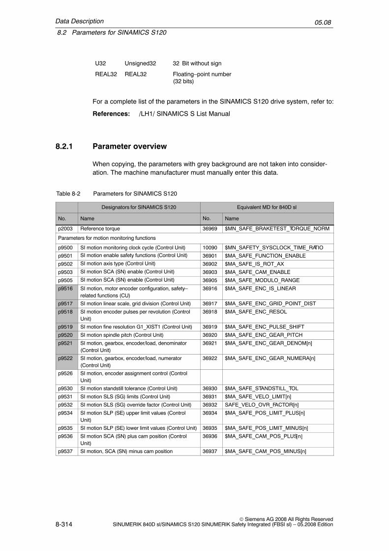
Data Description
8.2 Parameters for SINAMICS S120
05.08
8-314© Siemens AG 2008 All Rights Reserved
SINUMERIK 840D sl/SINAMICS S120 SINUMERIK Safety Integrated (FBSI sl) – 05.2008 Edition
U32 Unsigned32 32 Bit without sign
REAL32 REAL32 Floating–point number(32 bits)
For a complete list of the parameters in the SINAMICS S120 drive system, refer to:
References: /LH1/ SINAMICS S List Manual
8.2.1 Parameter overview
When copying, the parameters with grey background are not taken into consider-ation. The machine manufacturer must manually enter this data.
Table 8-2 Parameters for SINAMICS S120
Designators for SINAMICS S120 Equivalent MD for 840D sl
No. Name No. Name
p2003 Reference torque 36969 $MN_SAFE_BRAKETEST_TORQUE_NORM
Parameters for motion monitoring functions
p9500 SI motion monitoring clock cycle (Control Unit) 10090 $MN_SAFETY_SYSCLOCK_TIME_RATIO
p9501 SI motion enable safety functions (Control Unit) 36901 $MA_SAFE_FUNCTION_ENABLE
p9502 SI motion axis type (Control Unit) 36902 $MA_SAFE_IS_ROT_AX
p9503 SI motion SCA (SN) enable (Control Unit) 36903 $MA_SAFE_CAM_ENABLE
p9505 SI motion SCA (SN) enable (Control Unit) 36905 $MA_SAFE_MODULO_RANGE
p9516 SI motion, motor encoder configuration, safety–related functions (CU)
36916 $MA_SAFE_ENC_IS_LINEAR
p9517 SI motion linear scale, grid division (Control Unit) 36917 $MA_SAFE_ENC_GRID_POINT_DIST
p9518 SI motion encoder pulses per revolution (ControlUnit)
36918 $MA_SAFE_ENC_RESOL
p9519 SI motion fine resolution G1_XIST1 (Control Unit) 36919 $MA_SAFE_ENC_PULSE_SHIFT
p9520 SI motion spindle pitch (Control Unit) 36920 $MA_SAFE_ENC_GEAR_PITCH
p9521 SI motion, gearbox, encoder/load, denominator(Control Unit)
36921 $MA_SAFE_ENC_GEAR_DENOM[n]
p9522 SI motion, gearbox, encoder/load, numerator(Control Unit)
36922 $MA_SAFE_ENC_GEAR_NUMERA[n]
p9526 SI motion, encoder assignment control (ControlUnit)
p9530 SI motion standstill tolerance (Control Unit) 36930 $MA_SAFE_STANDSTILL_TOL
p9531 SI motion SLS (SG) limits (Control Unit) 36931 $MA_SAFE_VELO_LIMIT[n]
p9532 SI motion SLS (SG) override factor (Control Unit) 36932 SAFE_VELO_OVR_FACTOR[n]
p9534 SI motion SLP (SE) upper limit values (ControlUnit)
36934 $MA_SAFE_POS_LIMIT_PLUS[n]
p9535 SI motion SLP (SE) lower limit values (Control Unit) 36935 $MA_SAFE_POS_LIMIT_MINUS[n]
p9536 SI motion SCA (SN) plus cam position (ControlUnit)
36936 $MA_SAFE_CAM_POS_PLUS[n]
p9537 SI motion, SCA (SN) minus cam position 36937 $MA_SAFE_CAM_POS_MINUS[n]

Data Description
8.2 Parameters for SINAMICS S120
05.08
8-315© Siemens AG 2008 All Rights ReservedSINUMERIK 840D sl/SINAMICS S120 SINUMERIK Safety Integrated (FBSI sl) – 05.2008 Edition
Table 8-2 Parameters for SINAMICS S120
NameNo.NameNo.
p9538 SI motion SCA (SN) cam track assignment (ControlUnit)
36938 $MA_SAFE_CAM_TRACK_ASSIGN
p9540 SI motion SCA (SN) tolerance (Control Unit) 36940 $MA_SAFE_CAM_TOL
p9542 SI motion actual value comparison tolerance(crosswise) (Control Unit)
36942 $MA_SAFE_POS_TOL
p9544 SI motion actual value comparison tolerance (refer-encing) (CU)
36944 $MA_SAFE_REFP_POS_TOL
p9546 SI motion SSM (SGA n < nx) speed limit n_x (CU) 36946 $MA_SAFE_VELO_X
p9548 SI motion SBR actual speed tolerance (ControlUnit)
36948 $MA_SAFE_STOP_VELO_TOL
p9549 SI motion slip speed tolerance (Control Unit) 36949 $MA_SAFE_SLIP_VELO_TOL
p9550 SI motion SGE changeover tolerance time (ControlUnit)
36950 $MA_SAFE_MODE_SWITCH_TIME
p9551 SI motion SGE changeover delay time (ControlUnit)
36951 $MA_SAFE_VELO_SWITCH_DELAY
p9552 SI motion transition time STOP C to SOS (SBH)(Control Unit)
36952 $MA_SAFE_STOP_SWITCH_TIME_C
p9553 SI motion transition time STOP D to SOS (SBH)(Control Unit)
36953 $MA_SAFE_STOP_SWITCH_TIME_D
p9554 SI motion transition time STOP E to SOS (SBH)(Control Unit)
36954 $MA_SAFE_STOP_SWITCH_TIME_E
p9555 SI motion transition time STOP F to STOP B (Con-trol Unit)
36955 $MA_SAFE_STOP_SWITCH_TIME_F
p9556 SI motion pulse cancelation delay time (ControlUnit)
36956 $MA_SAFE_PULSE_DISABLE_DELAY
p9557 SI motion pulse cancelation checking time (ControlUnit)
36957 $MA_SAFE_PULSE_DIS_CHECK_TIME
p9558 SI motion acceptance test time limit (Control Unit) 36958 $MA_SAFE_ACCEPTANCE_TST_TIMEOUT
p9560 SI motion pulse cancelation shutdown speed (Con-trol Unit)
36960 $MA_SAFE_STANDSTILL_VELO_TOL
p9561 SI motion SLS (SG) stop response (Control Unit) 36961 $MA_SAFE_VELO_STOP_MODE
p9562 SI motion SLP (SE) stop response (Control Unit) 36962 $MA_SAFE_POS_STOP_MODE
p9563 SI motion SLS (SG)–specific stop response (Con-trol Unit)
36963 $MA_SAFE_VELO_STOP_REACTION[n]
p9570 SI motion acceptance test mode (Control Unit) Corresponds to BTSS variables for NCK
p9571 SI motion acceptance test status (Control Unit) Corresponds to BTSS variables for NCK
p9590 SI motion version safe motion monitoring (ControlUnit)
Parameters for basic safety functions integrated in the drive
p9601 SI enable functions integrated in the drive (ControlUnit)
p9602 SI enable safe brake control (Control Unit)
p9620 BI: SI signal source for STO (SH)/SBC/SS1 (Con-trol Unit)
p9650 SI SGE changeover tolerance time (Control Unit)
p9652 SI Safe Stop 1 delay time (Control Unit)
p9658 SI transition time STOP F to STOP A (Control Unit)
p9659 SI forced checking procedure, timer
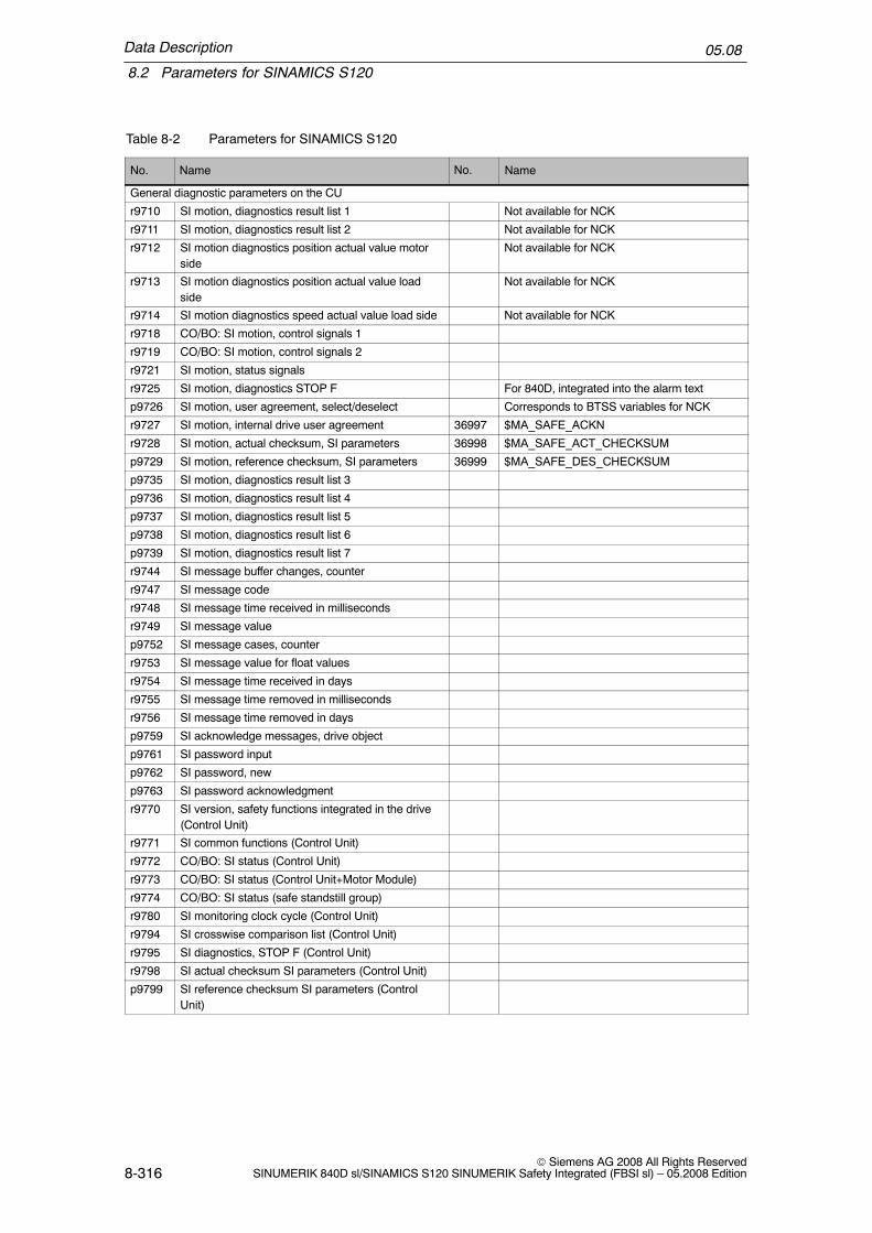
Data Description
8.2 Parameters for SINAMICS S120
05.08
8-316© Siemens AG 2008 All Rights Reserved
SINUMERIK 840D sl/SINAMICS S120 SINUMERIK Safety Integrated (FBSI sl) – 05.2008 Edition
Table 8-2 Parameters for SINAMICS S120
NameNo.NameNo.
General diagnostic parameters on the CU
r9710 SI motion, diagnostics result list 1 Not available for NCK
r9711 SI motion, diagnostics result list 2 Not available for NCK
r9712 SI motion diagnostics position actual value motorside
Not available for NCK
r9713 SI motion diagnostics position actual value loadside
Not available for NCK
r9714 SI motion diagnostics speed actual value load side Not available for NCK
r9718 CO/BO: SI motion, control signals 1
r9719 CO/BO: SI motion, control signals 2
r9721 SI motion, status signals
r9725 SI motion, diagnostics STOP F For 840D, integrated into the alarm text
p9726 SI motion, user agreement, select/deselect Corresponds to BTSS variables for NCK
r9727 SI motion, internal drive user agreement 36997 $MA_SAFE_ACKN
r9728 SI motion, actual checksum, SI parameters 36998 $MA_SAFE_ACT_CHECKSUM
p9729 SI motion, reference checksum, SI parameters 36999 $MA_SAFE_DES_CHECKSUM
p9735 SI motion, diagnostics result list 3
p9736 SI motion, diagnostics result list 4
p9737 SI motion, diagnostics result list 5
p9738 SI motion, diagnostics result list 6
p9739 SI motion, diagnostics result list 7
r9744 SI message buffer changes, counter
r9747 SI message code
r9748 SI message time received in milliseconds
r9749 SI message value
p9752 SI message cases, counter
r9753 SI message value for float values
r9754 SI message time received in days
r9755 SI message time removed in milliseconds
r9756 SI message time removed in days
p9759 SI acknowledge messages, drive object
p9761 SI password input
p9762 SI password, new
p9763 SI password acknowledgment
r9770 SI version, safety functions integrated in the drive(Control Unit)
r9771 SI common functions (Control Unit)
r9772 CO/BO: SI status (Control Unit)
r9773 CO/BO: SI status (Control Unit+Motor Module)
r9774 CO/BO: SI status (safe standstill group)
r9780 SI monitoring clock cycle (Control Unit)
r9794 SI crosswise comparison list (Control Unit)
r9795 SI diagnostics, STOP F (Control Unit)
r9798 SI actual checksum SI parameters (Control Unit)
p9799 SI reference checksum SI parameters (ControlUnit)

Data Description
8.2 Parameters for SINAMICS S120
05.08
8-317© Siemens AG 2008 All Rights ReservedSINUMERIK 840D sl/SINAMICS S120 SINUMERIK Safety Integrated (FBSI sl) – 05.2008 Edition
Table 8-2 Parameters for SINAMICS S120
NameNo.NameNo.
Parameters for functions integrated in the drive MM
p9801 SI enable safety functions (Motor Module)
p9802 SI enable safe brake control (Motor Module)
p9810 SI PROFIsafe address (Motor Module)
p9850 SI SGE changeover, tolerance time (Motor Module)
p9852 SI Safe Stop 1 delay time (Motor Module)
p9858 SI transition time STOP F to STOP A (MotorModule)
r9870 SI version (Motor Module)
r9871 SI common functions (Motor Module)
r9872 CO/BO: SI status (Motor Module)
r9880 SI monitoring clock cycle (Motor Module)
r9881 SI Sensor Module Node Identifier control
r9890 SI version (Sensor Module)
r9894 SI crosswise comparison list (Motor Module)
r9895 SI diagnostics, STOP F (Motor Module)
r9898 SI actual checksum SI parameters (Motor Module)
p9899 SI reference checksum SI parameters (MotorModule)
Downloading standard motor data
When standard motor data is downloaded some drive parameters are overwritten.If another type of motor is installed (e.g. after repairs have been carried out) andthe associated motor default data is downloaded, then the encoder data must bechanged back to its original value.

Data Description
8.2 Parameters for SINAMICS S120
05.08
8-318© Siemens AG 2008 All Rights Reserved
SINUMERIK 840D sl/SINAMICS S120 SINUMERIK Safety Integrated (FBSI sl) – 05.2008 Edition
8.2.2 Description of parameters
r0979[0....30] PROFIdrive encoder format/PD encoder format
Displays the position actual value encoder according to PROFIdrivethat is being used.[0] = header[1] = type, encoder 1[2] = resolution, encoder 1[3] = shift factor G1_XIST1[4] = shift factor G1_XIST2[5] = revolutions that can be distinguished, encoder 1[6] = reserved[7] = reserved[8] = reserved[9] = reserved[10] = reserved[11] = type, encoder 2[12] = resolution, encoder 2[13] = shift factor G2_XIST1[14] = shift factor G2_XIST2[15] = revolutions that can be distinguished, encoder 2[16] = reserved[17] = reserved[18] = reserved[19] = reserved[20] = reserved[21] = type, encoder 3[22] = resolution, encoder 3[23] = shift factor G3_XIST1[24] = shift factor G3_XIST2[25] = revolutions that can be distinguished, encoder 3[26] = reserved[27] = reserved[28] = reserved[29] = reserved[30] = reserved
Checksum: Protection level:3
Unit:–
Default value:–
Minimum value: Maximum value:–
Data type:U32
Effective:POWER ON
p1532[0...n] CO: Torque limit offset/M_max offset, CO: Force offset force limit/F_max offset
Sets the torque offset for the torque limit.Sets the force offset for the force limit.
Checksum: Protection level:3
Unit:–
Default value:–
Minimum value:–100000.00[Nm]–100000.00 [N]
Maximum value:100000.00[Nm]100000.00 [N]
Data type:Floating point
Effective:POWER ON

Data Description
8.2 Parameters for SINAMICS S120
05.08
8-319© Siemens AG 2008 All Rights ReservedSINUMERIK 840D sl/SINAMICS S120 SINUMERIK Safety Integrated (FBSI sl) – 05.2008 Edition
p2003 Reference torque
Setting the reference quantity for torques.All of the torques specified as relative value refer to this referencequantity. The reference quantity in this parameter corresponds to100% or 4000 hex or 4000 0000 hex.Note:For the automatic calculation (p0340 = 1, p3900 > 0) the correspond-ing pre–assignment is only made if the parameter is not inhibitedfrom being overwritten using p0573 = 1 (i.e. is not write protected).If a BICO interconnection is established between different physicalquantities, then the particular reference quantities are used as inter-nal conversion factor.Example:The actual value of the total torque (r0079) is interconnected to a testsocket (e.g. p0771[0]). The actual torque value is cyclically convertedinto a percentage of the reference torque (p2003) and is output corre-sponding to the selected scaling.
Checksum: Protection level:3
Unit:Nm
Default value:1.0
Minimum value:0.01
20000000.0 Data type:Floating point
Effective:POWER ON
Parameters for motion monitoring functions
p9500 SI motion monitoring clock cycle (Control Unit)
Sets the monitoring clock cycle for safety motion monitoring functions. Checksum:Yes
Protection level:3
Unit:ms
Default value:12
Minimum value:0.5
Maximum value:25
Data type:Floating point
Effective:POWER ON
Using p9500, the monitoring clock cycle for safety–related operation with a higher–level control is defined. p9500 must be an integer multiple of the position controllerclock cycle. If a value is entered into p9500 that is not an integer multiple of theposition controller clock cycle, then the value entered is rounded–off to the nextmultiple (integer multiple) of the position controller clock cycle and Fault F01652(”SI CU:Monitoring clock cycle not permissible”) is output with fault value 101.
Each time that a new connection is established for the clock–cycle synchronousPROFIBUS, the PROFIBUS master can specify a new position controller clockcycle; this is the reason that the check ”p9500 multiple integer of the position con-troller clock cycle” is repeated. Fault F01652 is output if an error occurs.
The Safety Integrated monitoring clock cycle is, just like all other SI drive parame-ters, a drive–specific monitoring clock cycle. However, different SI monitoring clockcycles within a drive system are not supported.

Data Description
8.2 Parameters for SINAMICS S120
05.08
8-320© Siemens AG 2008 All Rights Reserved
SINUMERIK 840D sl/SINAMICS S120 SINUMERIK Safety Integrated (FBSI sl) – 05.2008 Edition
p9501 SI motion enable safety functions (Control Unit)
Sets the enable signals for the safety–related motion monitoring functionsBit, signal name00 enable SOS/SLS (SBH/SG)01 enable SLP (SE)03 enable actual value synchronization04 enable external ESR activation05 enable override SLS (SG)06 enable external STOPs07 enable cam synchronization08 enable SCA1+ (SN1+)09 enable SCA1– (SN1–)10 enable SCA2+ (SN2+)11 enable SCA2– (SN2–)12 enable SCA3+ (SN3+)13 enable SCA3– (SN3–)14 enable SCA4+ (SN4+)15 enable SCA4– (SN4–)
Checksum:Yes
Protection level:3
Unit:–
Default value:0
Minimum value:0
Maximum value:0xFFFF FFFF
Data type:Unsigned32
Effective:POWER ON
The individual SI monitoring functions for a drive are enabled using p9501.
If one of the bits from bit 1 is set, then bit 0 must also be set. This is because for aSTOP C/D/E, the system changes into a safe operating stop. If this is not the case,Fault F01683 (”SI motion: SBH/SG enable missing”) is output.
p9502 SI motion axis type (Control Unit)Sets the axis type (linear axis or rotary axis/spindle)Linear axis = 01 = rotary axis/spindle
Checksum:Yes
Protection level:4
Unit:–
Default value:0
Minimum value:0
Maximum value:1
Data type:Integer16
Effective:POWER ON
For the commissioning software, after the axis type has been changed over, theunits that are dependent on the axis type are only updated after a project upload.

Data Description
8.2 Parameters for SINAMICS S120
05.08
8-321© Siemens AG 2008 All Rights ReservedSINUMERIK 840D sl/SINAMICS S120 SINUMERIK Safety Integrated (FBSI sl) – 05.2008 Edition
p9503 SI motion SCA (SN) enable (Control Unit)
Setting to enable the ”Safe software cams” function (SN)Bit, signal name00 enable SCA1 (SN1)01 enable SCA2 (SN2)02 enable SCA3 (SN3)03 enable SCA4 (SN4)04 enable SCA5 (SN5)05 enable SCA6 (SN6)06 enable SCA7 (SN7)07 enable SCA8 (SN8)08 enable SCA9 (SN9)09 enable SCA10 (SN10)10 enable SCA11 (SN11)11 enable SCA12 (SN12)12 enable SCA13 (SN13)13 enable SCA14 (SN14)14 enable SCA15 (SN15)15 enable SCA16 (SN16)16 enable SCA17 (SN17)17 enable SCA18 (SN18)18 enable SCA19 (SN19)19 enable SCA20 (SN20)20 enable SCA21 (SN21)21 enable SCA22 (SN22)22 enable SCA23 (SN23)23 enable SCA24 (SN24)24 enable SCA25 (SN25)25 enable SCA26 (SN26)26 enable SCA27 (SN27)27 enable SCA28 (SN28)28 enable SCA29 (SN29)29 enable SCA30 (SN30)
Checksum:Yes
Protection level:4
Unit:–
Default value:0
Minimum value:–
Maximum value:–
Data type:Unsigned32
Effective:POWER ON
The cam pairs 1 to 4 can also be enabled in p9501, bits 8–15. In this case, a 0must be in p9503. Vice versa, a 0 must be in p9501, bits 8–15 if cams are enabledin p9503. This is checked during booting and where relevant C01681 (”SI Motion:Monitoring function not supported”) is output with fault value 2.
p9505 SI motion SCA (SN) modulo value (Control Unit)Sets the modulo range of the safety position actual value in degrees for thefunction ”Safe cams” (SCA) for rotary axes.
Checksum:Yes
Protection level:4
Unit:–
Default value:0
Minimum value:0
Maximum value:737280
Data type:Floating point
Effective:POWER ON

Data Description
8.2 Parameters for SINAMICS S120
05.08
8-322© Siemens AG 2008 All Rights Reserved
SINUMERIK 840D sl/SINAMICS S120 SINUMERIK Safety Integrated (FBSI sl) – 05.2008 Edition
p9516 SI motion, motor encoder configuration, safety–related functions (CU)Sets the configuration for motor encoders and position actual valueBit 00: Motor encoder, rotary/linear1 signal: Linear, 0 signal: RotaryBit 01: Position actual value sign change1 signal: Yes, 0 signal: No
Checksum:Yes
Protection level:3
Unit:–
Default value:0
Minimum value:–
Maximum value:–
Data type:Unsigned16
Effective:POWER ON
The information whether a 1–encoder system or 2–encoder system is not includedin this parameter. This is derived from the parameter p9526 ”SI motion encoderassignment control”.p9516.0 corresponds to p0404.0. p9516.1 corresponds to p0410.1, but must beable to be parameterized independent of p0410.1.
p9517 SI motion linear scale, grid division (Control Unit)Sets the grid division for a linear motor encoder Checksum:
YesProtection level:3
Unit:nm
Default value:10 000
Minimum value:0
Maximum value:250 000 000
Data type:REAL32
Effective:POWER ON
Grid spacing of the linear motor encoder (this only applies to linear motor encoders).Corresponds to p0407.The following applies to safety–related functions that have been enabled (p9501 > 0):p9517 is checked to ensure that it coincides with p0407.
p9518 SI motion encoder pulses per revolution (Control Unit)Sets the number of encoder pulses per revolution for rotary motor encoders Checksum:
YesProtection level:3
Unit:�
Default value:2048
Minimum value:0
Maximum value:100 000
Data type:Unsigned32
Effective:POWER ON
Number of pulses per encoder revolution for motor encoders (only applies to rotarymotor encoders). Corresponds to p0408.The following applies to safety–related functions that have not been enabled(p9501 = 0): p9518 is automatically set the same as p0408 during booting.The following applies to safety–related functions that have been enabled (p9501 > 0):p9518 is checked to ensure that it coincides with p0408.

Data Description
8.2 Parameters for SINAMICS S120
05.08
8-323© Siemens AG 2008 All Rights ReservedSINUMERIK 840D sl/SINAMICS S120 SINUMERIK Safety Integrated (FBSI sl) – 05.2008 Edition
p9519 SI motion fine resolution G1_XIST1 (Control Unit)Sets the fine resolution for G1_XIST1 in bitsThe following applies to safety–related functions that have not been enabled(p9501 = 0):when booting, p9519 is automatically set the same as p0418.The following applies to safety–related functions that have been enabled(p9501 > 0):p9519 is checked to ensure that it coincides with p0418.
Checksum:Yes
Protection level:3
Unit:�
Default value:11
Minimum value:2
Maximum value:18
Data type:Unsigned32
Effective:POWER ON
Sets the fine resolution in bits of incremental position actual values for thePROFIBUS encoder interface. Corresponds to p0418.Comments regarding minimum and maximum value:� The minimum value is 2 so that the complete segment information is always
included in the position actual value and the check with the redundant coarseposition can always be made with the full 16–bit resolution.
� The maximum value is 18 so that at least 16 bits of coarse position informationare always included in the position actual value and the check with the redun-dant coarse position can always be made with the full 16–bit resolution.
p9520 SI motion spindle pitch (Control Unit)Sets the ratio between the encoder and load in mm/rev for a linear axis withrotary encoder
Checksum:Yes
Protection level:3
Unit:mm
Default value:10
Minimum value:0.1
Maximum value:8388
Data type:REAL32
Effective:POWER ON
p9521[0...7] SI motion, gearbox, encoder/load, denominator (Control Unit)Sets the denominator for the gearbox between the encoder and load. The ac-tual stage is selected using safety–related inputs (SGE).
Checksum:Yes
Protection level:3
Unit:–
Default value:1
Minimum value:1
Maximum value:2 147 000 000
Data type:Unsigned32
Effective:POWER ON
Denominator of the fraction ”number of encoder revolutions/number of load revo-lutions”.
There are a total of 8 values (8 indices of p9521), whereby, the actual value is se-lected using SGEs.
p9522[0...7] SI motion, gearbox, encoder/load, numerator (Control Unit)Sets the numerator for the gearbox between the encoder and load. The actualstage is selected using safety–related inputs (SGE).
Checksum:Yes
Protection level:3
Unit:–
Default value:1
Minimum value:1
Maximum value:2 147 000 000
Data type:Unsigned32
Effective:POWER ON
Numerator of the fraction ”number of encoder revolutions/number of load revo-lutions”.
There are a total of 8 values (8 indices of p9522), whereby, the actual value is se-lected using SGEs.
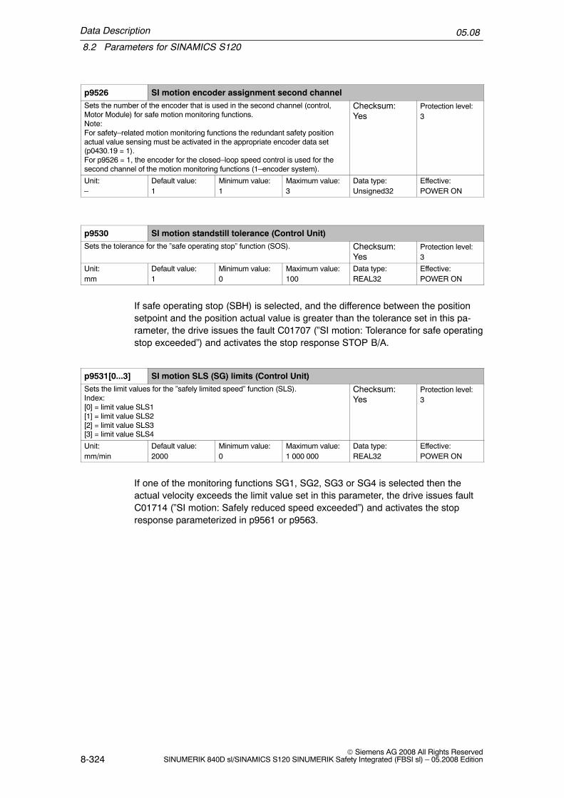
Data Description
8.2 Parameters for SINAMICS S120
05.08
8-324© Siemens AG 2008 All Rights Reserved
SINUMERIK 840D sl/SINAMICS S120 SINUMERIK Safety Integrated (FBSI sl) – 05.2008 Edition
p9526 SI motion encoder assignment second channelSets the number of the encoder that is used in the second channel (control,Motor Module) for safe motion monitoring functions.Note:For safety–related motion monitoring functions the redundant safety positionactual value sensing must be activated in the appropriate encoder data set(p0430.19 = 1).For p9526 = 1, the encoder for the closed–loop speed control is used for thesecond channel of the motion monitoring functions (1–encoder system).
Checksum:Yes
Protection level:3
Unit:–
Default value:1
Minimum value:1
Maximum value:3
Data type:Unsigned32
Effective:POWER ON
p9530 SI motion standstill tolerance (Control Unit)Sets the tolerance for the ”safe operating stop” function (SOS). Checksum:
YesProtection level:3
Unit:mm
Default value:1
Minimum value:0
Maximum value:100
Data type:REAL32
Effective:POWER ON
If safe operating stop (SBH) is selected, and the difference between the positionsetpoint and the position actual value is greater than the tolerance set in this pa-rameter, the drive issues the fault C01707 (”SI motion: Tolerance for safe operatingstop exceeded”) and activates the stop response STOP B/A.
p9531[0...3] SI motion SLS (SG) limits (Control Unit)Sets the limit values for the ”safely limited speed” function (SLS).Index:[0] = limit value SLS1[1] = limit value SLS2[2] = limit value SLS3[3] = limit value SLS4
Checksum:Yes
Protection level:3
Unit:mm/min
Default value:2000
Minimum value:0
Maximum value:1 000 000
Data type:REAL32
Effective:POWER ON
If one of the monitoring functions SG1, SG2, SG3 or SG4 is selected then theactual velocity exceeds the limit value set in this parameter, the drive issues faultC01714 (”SI motion: Safely reduced speed exceeded”) and activates the stopresponse parameterized in p9561 or p9563.

Data Description
8.2 Parameters for SINAMICS S120
05.08
8-325© Siemens AG 2008 All Rights ReservedSINUMERIK 840D sl/SINAMICS S120 SINUMERIK Safety Integrated (FBSI sl) – 05.2008 Edition
p9532[0...15] SI motion SLS (SG) override factor (Control Unit)Sets the override factor for the limit value for SG2 and SG4 of the function”safely reduced speed” (SG).
[0] = SLS (SG) override factor 0[1] = SLS (SG) override factor 1[2] = SLS (SG) override factor 2[3] = SLS (SG) override factor 3[4] = SLS (SG) override factor 4[5] = SLS (SG) override factor 5[6] = SLS (SG) override factor 6[7] = SLS (SG) override factor 7[8] = SLS (SG) override factor 8[9] = SLS (SG) override factor 9[10] = SLS (SG) override factor 10[11] = SLS (SG) override factor 11[12] = SLS (SG) override factor 12[13] = SLS (SG) override factor 13[14] = SLS (SG) override factor 14[15] = SLS (SG) override factor 15
Checksum:Yes
Protection level:4
Unit:%
Default value:100
Minimum value:0
Maximum value:100
Data type:Floating point
Effective:POWER ON
The actual override factor for SG2 and SG4 is selected using safety–related inputs(SGE).
p9534[0...1] SI motion SLP (SE) upper limit values (Control Unit)Sets the upper limit values for the ”safely limited position” function (SLP).Index:[0] = limit value SLP1 (SE1)[1] = limit value SLP2 (SE2)
Checksum:Yes
Protection level:4
Unit:mm, degrees
Default value:100 000
Minimum value:–2 147 000
Maximum value:2 147 000
Data type:REAL32
Effective:POWER ON
The following applies when setting the SE limit values: p9534 > p9535. If this con-dition is not fulfilled, the limit values are internally exchanged and fault F01684 (”SIMotion: Safe software limit switch values interchanged”) is output.
See also: p9501, p9535, p9562 and C01715 ”SI motion: Safe limit position ex-ceeded”.

Data Description
8.2 Parameters for SINAMICS S120
05.08
8-326© Siemens AG 2008 All Rights Reserved
SINUMERIK 840D sl/SINAMICS S120 SINUMERIK Safety Integrated (FBSI sl) – 05.2008 Edition
p9535[0...1] SI motion SLP (SE) lower limit values (Control Unit)Sets the lower limit values for the ”safely limited position” function (SLP).Index:[0] = limit value SLP1 (SE1)[1] = limit value SLP2 (SE2)
Checksum:Yes
Protection level:4
Unit:mm, degrees
Default value:–100 000
Minimum value:–2 147 000
Maximum value:2 147 000
Data type:REAL32
Effective:POWER ON
The following applies when setting the SE limit values: p9534 > p9535. If this con-dition is not fulfilled, the limit values are internally exchanged and fault F01684 (”SIMotion: Safe software limit switch values interchanged”) is output.
See also: p9501, p9534, p9562 and C01715 ”SI motion: Safe limit position ex-ceeded”.
p9536[0...29] SI motion SCA (SN) plus cam position (Control Unit)Sets the plus cam position for the ”safe cam” function (SCA).Index:[0] = cam position SCA1 (SN1)[1] = cam position SCA2 (SN2)[2] = cam position SCA3 (SN3)[3] = cam position SCA4 (SN4)[4] = cam position SCA5 (SN5)[5] = cam position SCA6 (SN6)[6] = cam position SCA7 (SN7)[7] = cam position SCA8 (SN8)[8] = cam position SCA9 (SN9)[9] = cam position SCA10 (SN10)[10] = cam position SCA11 (SN11)[11] = cam position SCA12 (SN12)[12] = cam position SCA13 (SN13)[13] = cam position SCA14 (SN14)[14] = cam position SCA15 (SN15)[15] = cam position SCA16 (SN16)[16] = cam position SCA17 (SN17)[17] = cam position SCA18 (SN18)[18] = cam position SCA19 (SN19)[19] = cam position SCA20 (SN20)[20] = cam position SCA21 (SN21)[21] = cam position SCA22 (SN22)[22] = cam position SCA23 (SN23)[23] = cam position SCA24 (SN24)[24] = cam position SCA25 (SN25)[25] = cam position SCA26 (SN26)[26] = cam position SCA27 (SN27)[27] = cam position SCA28 (SN28)[28] = cam position SCA29 (SN29)[29] = cam position SCA30 (SN30)
Checksum:Yes
Protection level:4
Unit:mm, degrees
Default value:10
Minimum value:–2 147 000
Maximum value:2 147 000
Data type:Floating point
Effective:POWER ON
See also: p9501, p9503, p9537

Data Description
8.2 Parameters for SINAMICS S120
05.08
8-327© Siemens AG 2008 All Rights ReservedSINUMERIK 840D sl/SINAMICS S120 SINUMERIK Safety Integrated (FBSI sl) – 05.2008 Edition
p9537[0...29] SI motion SCA (SN) minus cam position (Control Unit)Sets the minus cam position for the ”Safe Cam” function (SCA).Index:[0] = cam position SCA1 (SN1)[1] = cam position SCA2 (SN2)[2] = cam position SCA3 (SN3)[3] = cam position SCA4 (SN4)[4] = cam position SCA5 (SN5)[5] = cam position SCA6 (SN6)[6] = cam position SCA7 (SN7)[7] = cam position SCA8 (SN8)[8] = cam position SCA9 (SN9)[9] = cam position SCA10 (SN10)[10] = cam position SCA11 (SN11)[11] = cam position SCA12 (SN12)[12] = cam position SCA13 (SN13)[13] = cam position SCA14 (SN14)[14] = cam position SCA15 (SN15)[15] = cam position SCA16 (SN16)[16] = cam position SCA17 (SN17)[17] = cam position SCA18 (SN18)[18] = cam position SCA19 (SN19)[19] = cam position SCA20 (SN20)[20] = cam position SCA21 (SN21)[21] = cam position SCA22 (SN22)[22] = cam position SCA23 (SN23)[23] = cam position SCA24 (SN24)[24] = cam position SCA25 (SN25)[25] = cam position SCA26 (SN26)[26] = cam position SCA27 (SN27)[27] = cam position SCA28 (SN28)[28] = cam position SCA29 (SN29)[29] = cam position SCA30 (SN30)
Checksum:Yes
Protection level:4
Unit:mm, degrees
Default value:–10
Minimum value:–2 147 000
Maximum value:2 147 000
Data type:Floating point
Effective:POWER ON
See also: p9501, p9503, p9537
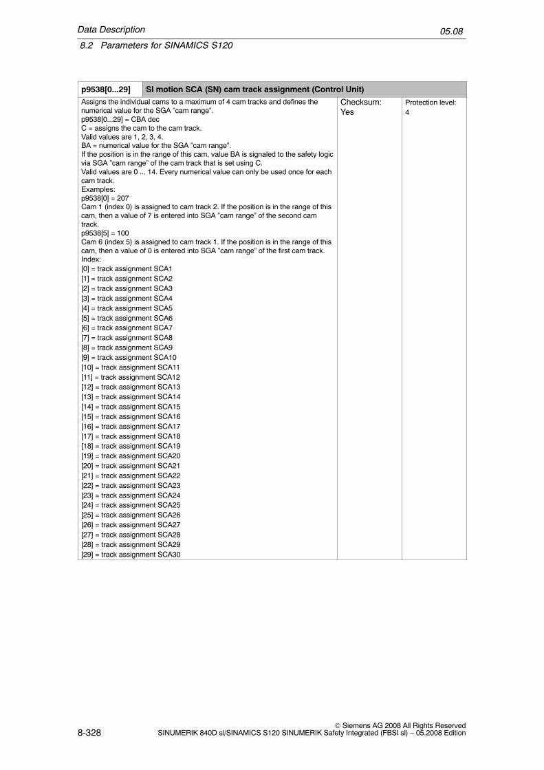
Data Description
8.2 Parameters for SINAMICS S120
05.08
8-328© Siemens AG 2008 All Rights Reserved
SINUMERIK 840D sl/SINAMICS S120 SINUMERIK Safety Integrated (FBSI sl) – 05.2008 Edition
p9538[0...29] SI motion SCA (SN) cam track assignment (Control Unit)Assigns the individual cams to a maximum of 4 cam tracks and defines thenumerical value for the SGA ”cam range”.p9538[0...29] = CBA decC = assigns the cam to the cam track.Valid values are 1, 2, 3, 4.BA = numerical value for the SGA ”cam range”.If the position is in the range of this cam, value BA is signaled to the safety logicvia SGA ”cam range” of the cam track that is set using C.Valid values are 0 ... 14. Every numerical value can only be used once for eachcam track.Examples:p9538[0] = 207Cam 1 (index 0) is assigned to cam track 2. If the position is in the range of thiscam, then a value of 7 is entered into SGA ”cam range” of the second camtrack.p9538[5] = 100Cam 6 (index 5) is assigned to cam track 1. If the position is in the range of thiscam, then a value of 0 is entered into SGA ”cam range” of the first cam track.Index:[0] = track assignment SCA1[1] = track assignment SCA2[2] = track assignment SCA3[3] = track assignment SCA4[4] = track assignment SCA5[5] = track assignment SCA6[6] = track assignment SCA7[7] = track assignment SCA8[8] = track assignment SCA9[9] = track assignment SCA10[10] = track assignment SCA11[11] = track assignment SCA12[12] = track assignment SCA13[13] = track assignment SCA14[14] = track assignment SCA15[15] = track assignment SCA16[16] = track assignment SCA17[17] = track assignment SCA18[18] = track assignment SCA19[19] = track assignment SCA20[20] = track assignment SCA21[21] = track assignment SCA22[22] = track assignment SCA23[23] = track assignment SCA24[24] = track assignment SCA25[25] = track assignment SCA26[26] = track assignment SCA27[27] = track assignment SCA28[28] = track assignment SCA29[29] = track assignment SCA30
Checksum:Yes
Protection level:4

Data Description
8.2 Parameters for SINAMICS S120
05.08
8-329© Siemens AG 2008 All Rights ReservedSINUMERIK 840D sl/SINAMICS S120 SINUMERIK Safety Integrated (FBSI sl) – 05.2008 Edition
Unit: Default value:
[0] 100[1] 101[2] 102[3] 103[4] 104[5] 105[6] 106[7] 107[8] 108[9] 109[10] 110[11] 111[12] 112[13] 113[14] 114[15] 200[16] 201[17] 202[18] 203[19] 204[20] 205[21] 206[22] 207[23] 208[24] 209[25] 210[26] 211[27] 212[28] 213[29] 214
Minimum value:100
Maximum value:414
Data type:U32
Effective:POWER ON
p9540 SI motion SCA (SN) tolerance (Control Unit)Sets the tolerance for the ”Safe Cam” function (SCA).Within this tolerance, both monitoring channels may signal different signalstates of the same safe cam.
Checksum:Yes
Protection level:4
Unit:mm, degrees
Default value:0.1
Minimum value:0.001
Maximum value:10 mm or 10 degrees
Data type:Floating point
Effective:POWER ON
p9542 SI motion actual value comparison tolerance (crosswise) (Control Unit)Sets the tolerance in mm or Degrees for the crosswise comparison of theactual position between the two monitoring channels
Checksum:Yes
Protection level:3
Unit:mm
Default value:0.1
Minimum value:0.001
Maximum value:10 mm or 360 de-grees
Data type:Floating point
Effective:POWER ON
See also: C01711 ”SI motion: Defect in a monitoring channel”.

Data Description
8.2 Parameters for SINAMICS S120
05.08
8-330© Siemens AG 2008 All Rights Reserved
SINUMERIK 840D sl/SINAMICS S120 SINUMERIK Safety Integrated (FBSI sl) – 05.2008 Edition
p9544 SI motion actual value comparison tolerance (referencing) (Control Unit)Sets the tolerance in mm or Degrees to check the actual values after referenc-ing (incremental encoder) or when powering–up (absolute encoder).
Checksum:Yes
Protection level:4
Unit:mm, inches,degrees
Default value:0.01
Minimum value:0
Maximum value:36 mm or 36 de-grees
Data type:REAL32
Effective:POWER ON
See also: C01711 ”SI motion: Defect in a monitoring channel”.
p9546 SI motion SSM (SGA n < nx) speed limit n_x (CU)Sets the speed limit for the SSM feedback signal (n < n_x) to identify zerospeed.If this limit value is fallen below, the signal ”SSM feedback signal active” (SGAn < n_x) is set.Caution: After the set threshold value is fallen below, the ”safety accelerationmonitor” function (SBR) is switched out
Checksum:Yes
Protection level:3
Unit:mm/minRPM
Default value:20
Minimum value:0
Maximum value:1000 000
Data type:Floating point
Effective:POWER ON
p9548 SI motion SBR actual speed tolerance (Control Unit)Sets the speed tolerance for the ”safe acceleration monitoring” (SBR) Checksum:
YesProtection level:3
Unit:mm/minRPM
Default value:300
Minimum value:0
Maximum value:120 000
Data type:Floating point
Effective:POWER ON
See also: C01706 ”SI motion: Safe acceleration monitoring limit exceeded”.
After initiating the safe acceleration monitoring (SBR) for the stop responses STOPB and STOP C, the actual velocity plus the tolerance value parameterized in p9548may not exceed the actual speed sensed in the last monitoring clock cycle. Ifp9548 > 0, then the value converted into the internal format is limited to greaterthan or equal to 1.
p9549 SI motion slip speed tolerance (Control Unit)Sets the velocity tolerance in mm/min or rpm, that is used for a 2–encodersystem in a crosswise comparison between the drive and control. If the actualvalue synchronization is not enabled (p9501 3 = 0), then the value parameter-ized in p9542 is used as tolerance in the crosswise data comparison.
Checksum:Yes
Protection level:3
Unit:mm/minRPM
Default value:6
Minimum value:0
Maximum value:6000
Data type:Floating point
Effective:POWER ON

Data Description
8.2 Parameters for SINAMICS S120
05.08
8-331© Siemens AG 2008 All Rights ReservedSINUMERIK 840D sl/SINAMICS S120 SINUMERIK Safety Integrated (FBSI sl) – 05.2008 Edition
p9550 SI motion SGE changeover tolerance time (Control Unit)Sets the tolerance time to change over the safety–related inputs (SGE) Checksum:
YesProtection level:4
Unit:ms
Default value:500
Minimum value:0
Maximum value:10 000
Data type:REAL32
Effective:POWER ON
Because of the different runtimes of the two monitoring channels – drive and con-trol – a SGE changeover is not effective at the same time. After a SGE change-over, a crosswise data comparison of the dynamic data is not carried out duringthis tolerance time (actual values, result lists, ...). However, the monitoring func-tions remain active during this time.
p9551 SI motion SLS(SG) changeover delay time (Control Unit)Sets the delay time for the SLS changeover or for the changeover from SLS toSOS for the ”safely limited speed” function (SLS).At the transition from a higher to a lower safely limited speed stage or to a safeoperating stop (SOS), the ”old” speed stage remains active for this delay time.Also from non safety–related operation, when SLS or SOS is activated, thisdelay still applies.
Checksum:Yes
Protection level:4
Unit:ms
Default value:100
Minimum value:0
Maximum value:600 000
Data type:Floating point
Effective:POWER ON
p9552 SI motion transition time STOP C to SOS (SBH) (Control Unit)Sets the transition time from STOP C to ”Safe Operating Stop” (SOS). Checksum:
YesProtection level:3
Unit:ms
Default value:100
Minimum value:0
Maximum value:600 000
Data type:Floating point
Effective:POWER ON
p9553 SI motion transition time STOP D to SOS (SBH) (Control Unit)Sets the transition time from STOP D to ”Safe Operating Stop” (SOS) Checksum:
YesProtection level:3
Unit:ms
Default value:100
Minimum value:0
Maximum value:600 000
Data type:Floating point
Effective:POWER ON
p9554 SI motion transition time STOP E to SOS (SBH) (Control Unit)Sets the transition time from STOP E to ”Safe Operating Stop” (SOS) Checksum:
YesProtection level:4
Unit:ms
Default value:100
Minimum value:0
Maximum value:600 000
Data type:REAL32
Effective:POWER ON

Data Description
8.2 Parameters for SINAMICS S120
05.08
8-332© Siemens AG 2008 All Rights Reserved
SINUMERIK 840D sl/SINAMICS S120 SINUMERIK Safety Integrated (FBSI sl) – 05.2008 Edition
p9555 SI motion transition time STOP F to STOP B (Control Unit)Sets the transition time from STOP F to STOP B Checksum:
YesProtection level:3
Unit:ms
Default value:0
Minimum value:0
Maximum value:600 000
Data type:Floating point
Effective:POWER ON
See also: C01711 ”SI motion defect in a monitoring channel”
p9556 SI motion pulse cancelation delay time (Control Unit)Sets the delay time for the safe pulse cancellation after STOP B Checksum:
YesProtection level:3
Unit:ms
Default value:100
Minimum value:0
Maximum value:600 000
Data type:Floating point
Effective:POWER ON
STOP B causes the drive to brake along the OFF3 ramp. Stop response STOP Ais initiated after the time parameterized in p9556 has expired or after the speedthreshold parameterized in p9560 has been fallen below.
See also: C01701 ”SI motion, STOP B initiated”.
p9557 SI motion pulse cancelation checking time (Control Unit)Sets the time after which the pulses must have been cancelled after initiatingthe test stop.
Checksum:Yes
Protection level:3
Unit:ms
Default value:100
Minimum value:0
Maximum value:10 000
Data type:Floating point
Effective:POWER ON
If the pulses have been correctly cancelled via the shutdown path of the monitoringchannel after the time parameterized in p9557, then this is communicated to theuser by setting SGA ”pulses are cancelled”. If an error occurred while testing theshutdown path, stop response STOP A is initiated.
See also: C01798 ”SI motion: ”Test stop running”.
p9558 SI motion acceptance test mode time limit (Control Unit)Sets the maximum time for the acceptance test mode. If the acceptance testmode lasts longer than the selected time limit, then the mode is automaticallyexited.
Checksum:Yes
Protection level:3
Unit:ms
Default value:40 000
Minimum value:5 000
Maximum value:100 000
Data type:Floating point
Effective:POWER ON
See also: C01799 ”SI motion: Acceptance test mode is active”.

Data Description
8.2 Parameters for SINAMICS S120
05.08
8-333© Siemens AG 2008 All Rights ReservedSINUMERIK 840D sl/SINAMICS S120 SINUMERIK Safety Integrated (FBSI sl) – 05.2008 Edition
p9560 SI motion pulse cancelation shutdown speed (Control Unit)Sets the shutdown speed for pulse cancellation. ”Standstill” (zero speed) isassumed below this speed and for STOP B, the pulses are cancelled (as aresult of a transition to STOP A).
Checksum:Yes
Protection level:3
Unit:mm/min,RPM
Default value:0
Minimum value:0
Maximum value:6000
Data type:Floating point
Effective:POWER ON
STOP B causes the drive to brake along the OFF3 ramp. Stop response STOP Ais initiated after the time parameterized in p9556 has expired or after the speedthreshold parameterized in p9560 has been fallen below.
p9561 SI motion SLS (SG) stop response (Control Unit)Sets the stop response for the ”safely limited speed” function (SLS).This setting applies to all SLS limit values.An input value of less than 5 signifies protection for personnel, from 10 andonwards, machine protection.0: STOP A1: STOP B2: STOP C3: STOP D4: STOP E5: Set the stop response using p9563 (SG–specific)10: STOP A with delayed pulse cancellation when the bus fails11: STOP B with delayed pulse cancellation when the bus fails12: STOP C with delayed pulse cancellation when the bus fails13: STOP D with delayed pulse cancellation when the bus fails14: STOP E with delayed pulse cancellation when the bus fails
Checksum:Yes
Protection level:4
Unit:–
Default value:5
Minimum value:0
Maximum value:14
Data type:Integer16
Effective:POWER ON
See also: p9531, p9563
p9562 SI motion SLP (SE) stop response (Control Unit)Sets the stop response for the ”safely limited position” function (SLP).2: STOP C3: STOP D4: STOP E
Checksum:Yes
Protection level:4
Unit:–
Default value:2
Minimum value:2
Maximum value:4
Data type:Integer16
Effective:POWER ON
See also: p9536, p9537

Data Description
8.2 Parameters for SINAMICS S120
05.08
8-334© Siemens AG 2008 All Rights Reserved
SINUMERIK 840D sl/SINAMICS S120 SINUMERIK Safety Integrated (FBSI sl) – 05.2008 Edition
p9563[0...3] SI motion SLS (SG)–specific stop response (Control Unit)Sets the SLS–specific stop response for the ”safely limited speed” function(SLS).These settings apply to the individual limit values for SLS.0: STOP A1: STOP B2: STOP C3: STOP D4: STOP E10: STOP A with delayed pulse cancellation when the bus fails11: STOP B with delayed pulse cancellation when the bus fails12: STOP C with delayed pulse cancellation when the bus fails13: STOP D with delayed pulse cancellation when the bus fails14: STOP E with delayed pulse cancellation when the bus failsIndex:[0] = limit value SG1[1] = limit value SG2[2] = limit value SG3[3] = limit value SG4
Checksum:Yes
Protection level:3
Unit:–
Default value:2
Minimum value:0
Maximum value:14
Data type:Integer16
Effective:POWER ON
When the speed limit, parameterized in p9531 is exceeded, if the SG monitoring isactive, the stop response parameterized in p9563 is initiated.
p9570 SI motion acceptance test mode (Control Unit)Setting to select/deselect the acceptance test mode0: [00 hex] Deselect acceptance test mode0xAC: [AC hex] Select acceptance mode
Checksum:No
Protection level:3
Unit:–
Default value:0
Minimum value:0
Maximum value:0xAC
Data type:Integer16
Effective:Immediately
See also: p9558, r9571
r9571 SI motion acceptance test status (Control Unit)Displays the status of the acceptance test mode0: [00 hex] accept_mode inactive12: [0C hex] accept_mode not possible due to power on fault13: [0D hex] accept_mode not possible due to incorrect ID in p957015: [0F hex] accept_mode not possible due to expired accept_timer172: [AC hex] accept_mode active
Checksum:No
Protection level:3
Unit:–
Default value:0
Minimum value:0
Maximum value:0xAC
Data type:U16
Effective:–
See also: C01799 ”SI motion, acceptance test mode active”

Data Description
8.2 Parameters for SINAMICS S120
05.08
8-335© Siemens AG 2008 All Rights ReservedSINUMERIK 840D sl/SINAMICS S120 SINUMERIK Safety Integrated (FBSI sl) – 05.2008 Edition
r9590[0...2] SI motion version safe motion monitoring functions (Control Unit)Displays the Safety Integrated version for safe motion monitoring functions onthe Control Unit.[0] = Safety Version (major release)[1] = Safety Version (minor release)[2] = Safety Version (baselevel or patch)Example:r9590[0] = 2, r9590[1] = 3, r9590[2] = 1 ––> SI motion version V02.03.01
Checksum: Protection level:3
Unit:–
Default value:–
Minimum value:–
Maximum value:–
Data type:Unsigned16
Effective:
See also: r9770, r9870, r9890
Parameters for basic safety functions integrated in the drive
These parameters are also relevant for the motion monitoring functions as the safestandstill is carried out by monitoring functions integrated in the drive. See Chapter6.1 ”Safe standstill (SH)”.
p9601 SI enable functions integrated in the drive (Control Unit)Sets the enable signals for safety functions integrated in the drive on the Con-trol UnitBit Signal name00 STO (SH) enable via terminals (Control Unit)
Checksum:Yes
Protection level:3
Unit:–
Default value:0000 bin
Minimum value:–
Maximum value:–
Data type:Unsigned32
Effective:When exiting theSI commissioningmode
It is permissible to simultaneously enable the safety functions integrated in thedrive (p9601/p9801 < > 0) and the motion monitoring functions (p9501 < > 0).See also: p9801

Data Description
8.2 Parameters for SINAMICS S120
05.08
8-336© Siemens AG 2008 All Rights Reserved
SINUMERIK 840D sl/SINAMICS S120 SINUMERIK Safety Integrated (FBSI sl) – 05.2008 Edition
p9602 SI enable safe brake control (Control Unit)Sets the enable signal for the function safe brake control (SBC) on the ControlUnit.0: SBC not enabled1: Close the holding brake when SH is selected or when SI errors occurThe safe brake control function only becomes active if at least one safety moni-toring function is enabled (i.e. p9501 not equal to 0 and/or p9601/p9801 notequal to 0).If a motor holding brake is not being used then it does not make any sense toenable the parameterization ”no motor holding brake available” and ”safe brakecontrol” (p1215 = 0, p9602 = p9802 = 1).The parameterization ”motor holding brake the same as sequence control,connection via BICO” and ”safe brake control” enabled (p1215 = 3, p9602 = 1,p9802 = 1) does not make sense.The parameterization ”motor holding brake without feedback signals” and ”safebrake control” enabled (p1278 = 1, p9602 = 1, p9802 = 1) is not permissible.
Checksum:Yes
Protection level:3
Unit:–
Default value:0
Minimum value:0
Maximum value:1
Data type:Integer16
Effective:When exiting theSI commissioningmode
If p9602 = 1, the holding braking is closed when SH is selected or SI errors occur.P9602 has priority over p1215 (”holding brake setting”).
See also: p9802
p9620 BI: SI signal source for STO (SH)/SBC/SS1 (Control Unit)Sets the signal source for the following functions on the Control Unit:STO: Safe Torque Off/SH: Safe standstillSBC: Safe Brake ControlSS1: Safe Stop 1 (SS1, time monitored)Depends on: See also: p9601Note: The following signal sources are permitted:– fixed zero (standard setting).– digital inputs (DI 0 to DI 7 on the Control Unit NCU7xx.– digital inputs DI 0 to DI 3 on the Controller Extensions (CX32, NX10, NX15).– digital inputs (DI 0 to DI 3 on the Control Unit 310 (CU310).It is not permitted to interconnect to a digital input is in simulation mode.
Checksum:No
Protection level:3
Unit:–
Default value:0
Minimum value:–
Maximum value:–
Data type:Unsigned32
Effective:

Data Description
8.2 Parameters for SINAMICS S120
05.08
8-337© Siemens AG 2008 All Rights ReservedSINUMERIK 840D sl/SINAMICS S120 SINUMERIK Safety Integrated (FBSI sl) – 05.2008 Edition
p9650 SI tolerance time SGE changeover integrated in the drive (Control Unit)Sets the tolerance time to change over the safety–related inputs (SGE) for themonitoring functions integrated in the drive on the Control Unit. Because of thedifferent runtimes of the two monitoring channels, an SIS switchover is noteffective at the same time. After an SIS switchover, a cross–comparison of thedynamic data is not carried out during this tolerance time.For a crosswise data comparison between p9650 and p9850, a difference ofone safety monitoring clock cycle is tolerated. The parameterized time is inter-nally rounded–off to an integer multiple of the monitoring clock cycle.
Checksum:Yes
Protection level:3
Unit:ms
Default value:500
Minimum value:0
Maximum value:2 000.00
Data type:REAL32
Effective:When exiting theSI commissioningmode
See also: p9850
p9652 SI Safe Stop 1 delay time (Control Unit)Sets the delay time of the pulse cancellation for the function ”Safe Stop 1”(SS1) on the Control Unit to brake along the OFF3 down ramp (p1135).For a crosswise data comparison between p9652 and p9852, a difference ofone safety monitoring clock cycle is tolerated. The parameterized time is inter-nally rounded–off to an integer multiple of the monitoring clock cycle.
Checksum:Yes
Protection level:3
Unit:s
Default value:0.00
Minimum value:0.00
Maximum value:300.00
Data type:Floating point
Effective:
See also: p1135, p9852
p9658 SI transition time STOP F to STOP A (Control Unit)Sets the transition time from STOP F to STOP A on the Control Unit.For a crosswise data comparison between p9658 and p9858, a difference ofone safety monitoring clock cycle is tolerated. The parameterized time is inter-nally rounded–off to an integer multiple of the monitoring clock cycle.STOP F: Defect in a monitoring channel (error in the crosswise data compari-son)STOP A: Pulse deletion via safety shutdown path
Checksum:Yes
Protection level:3
Unit:ms
Default value:0
Minimum value:0
Maximum value:30 000.00
Data type:Floating point
Effective:When exiting theSI commissioningmode
See also: F01611

Data Description
8.2 Parameters for SINAMICS S120
05.08
8-338© Siemens AG 2008 All Rights Reserved
SINUMERIK 840D sl/SINAMICS S120 SINUMERIK Safety Integrated (FBSI sl) – 05.2008 Edition
p9659 SI forced checking procedure, timerSets the time to carry out the dynamic update and testing the safety shutdownpaths (forced checking procedure).Within the parameterized time, safe standstill must have been deselected atleast once. The monitoring time is reset at every SH deselection.
Checksum:Yes
Protection level:3
Unit:h
Default value:8
Minimum value:0
Maximum value:9 000
Data type:Floating point
Effective:Immediately
Within the parameterized time grid, the user must subject the safety shutdownpaths to a forced checking procedure and test them; this means he must carry outan SH selection/deselection. If the user does not do this, then after this time usingthe Alarm A01699 (”SI CU: Necessary to test the shutdown paths”) he will be re-quested to test the shutdown paths, i.e. select/deselect SH. In so doing, r9773, bit31 is set to 1.
The timer to carry out the forced checking procedure is reset to the parameterizedvalue:� each time the drive has booted� each time that SH is selected� each time that p9659 is set
General diagnostic parameters on the CU
r9710[0...1] SI motion, diagnostics result list 1Display of result list 1 which led to an error for a crosswise data comparisonbetween the two monitoring channels.[0]: Result list second channel[1]: Result list driveBit 00: Actual value > Upper limit SOSBit 01: Actual value > Lower limit SOSBit 02: Actual value> Upper limit SE1Bit 03: Actual value > Lower limit SE1Bit 04: Actual value> Upper limit SE2Bit 05: Actual value > Lower limit SE2Bit 06: Actual value> Upper limit SG1Bit 07: Actual value > Lower limit SG1Bit 08: Actual value > Upper limit SG2Bit 09: Actual value > Lower limit SG2Bit 10: Actual value > Upper limit SG3Bit 11: Actual value > Lower limit SG3Bit 12: Actual value > Upper limit SG4Bit 13: Actual value > Lower limit SG4Bit 16: Actual value> Upper limit SBRBit 17: Actual value > Lower limit SBR
Checksum:No
Protection level:3
Unit:–
Default value:–
Minimum value:–
Maximum value:–
Data type:Unsigned32
Effective:–
See also: C01711 ”SI motion: Defect in a monitoring channel”.

Data Description
8.2 Parameters for SINAMICS S120
05.08
8-339© Siemens AG 2008 All Rights ReservedSINUMERIK 840D sl/SINAMICS S120 SINUMERIK Safety Integrated (FBSI sl) – 05.2008 Edition
r9711[0...1] SI motion, diagnostics result list 2Display of result list 2, which led to an error between the two monitoring chan-nels for a crosswise data comparison.[0]: Result list second channel[1]: Result list driveBit 00 Actual value > Upper limit SN1+Bit 01 Actual value > Lower limit SN1+Bit 02 Actual value > Upper limit SN1–Bit 03 Actual value > Lower limit SN1–Bit 04 Actual value > Upper limit SN2+Bit 05 Actual value > Lower limit SN2+Bit 06 Actual value > Upper limit SN2–Bit 07 Actual value > Lower limit SN2–Bit 08 Actual value > Upper limit SN3+Bit 09 Actual value > Lower limit SN3+Bit 10 Actual value > Upper limit SN3–Bit 11 Actual value > Lower limit SN3–Bit 12 Actual value > Upper limit SN4+Bit 13 Actual value > Lower limit SN4+Bit 14 Actual value > Upper limit SN4–Bit 15 Actual value > Lower limit SN4–Bit 16 Actual value > Upper limit nx+Bit 17 Actual value > Lower limit nx +Bit 18 Actual value > Upper limit nx –Bit 19 Actual value > Lower limit nx –Bit 20 Actual value > Upper limit moduloBit 21 Actual value > Lower limit modulo
Checksum:No
Protection level:3
Unit:–
Default value:–
Minimum value:–
Maximum value:–
Data type:Unsigned32
Effective:–
See also: C01711 ”SI motion: Defect in a monitoring channel”
r9712 SI motion diagnostics position actual value motor sideDisplay of the actual position actual value on the motor side for the motion mon-itoring functions on the Control Unit.
Checksum: Protection level:3
Unit:–
Default value:–
Minimum value:–
Maximum value:–
Data type:Unsigned32
Effective:–
r9713 SI motion diagnostics position actual value load sideDisplays the actual position actual value on the load side of the two monitoringchannels and their difference.[0] = load side actual value on the Control Unit[1] = load side actual value on the second channel[2] = load side actual value difference Control Unit – second channelre r9713[0]:The display of the load side position actual value on the Control Unit is updatedin the monitoring clock cycle.re r9713[0]:The display of the load side position actual value on the second channel isupdated in the crosswise data comparison clock cycle (r9724) and is realized,delayed by one crosswise data comparison clock cycle.re r9713[2]:The difference between the load side position actual value on the Control Unitand the load side position actual value on the second channel is updated in thecrosswise data comparison clock cycle (r9724) and is realized, delayed by onecrosswise data comparison clock cycle.
Checksum: Protection level:3
Unit:–
Default value:–
Minimum value:–
Maximum value:–
Data type:Unsigned32
Effective:–

Data Description
8.2 Parameters for SINAMICS S120
05.08
8-340© Siemens AG 2008 All Rights Reserved
SINUMERIK 840D sl/SINAMICS S120 SINUMERIK Safety Integrated (FBSI sl) – 05.2008 Edition
r9714 SI motion diagnostics speed actual value load sideDisplay of the actual load side speed value for the motion monitoring functionson the Control Unit.For linear axes, the following units apply: Micrometers per monitoring clockcycle (p9500).For rotary axes, the following units apply: Millidegrees per monitoring clockcycle (p9500).
Checksum:No
Protection level:3
Unit:–
Default value:–
Minimum value:–
Maximum value:–
Data type:Integer32
Effective:–
r9718 CO/BO: SI motion, control signals 1Control signals 1 for the safe motion monitoring functions.Bit 23: Set the offset for travel to fixed stop to the actual torque1 signal: Set, 0 signal: Reset
Checksum:No
Protection level:4
Unit:–
Default value:–
Minimum value:–
Maximum value:–
Data type:Unsigned32
Effective:–
r9719 CO/BO: SI motion, control signals 2Control signals 2 for the safe motion monitoring functions.Bit, signal name00 deselect SOS/SLS (SBH/SG) 1 signal: Yes, 0 signal: No01 deselect SOS (SBH) 1 signal: Yes, 0 signal: No03 select SLS (SG) bit 0, 1 signal: Set, 0 signal: Not set04 select SLS (SG) bit 1, 1 signal: Set, 0 signal: Not set08 gear selection bit 0, 1 signal: Set, 0 signal: Not set09 gear selection bit 1, 1 signal: Set, 0 signal: Not set10 gear selection bit 2, 1 signal: Set, 0 signal: Not set12 select SLP (SE) 1 signal: SLP2 (SE2), 0 signal: SLP1 (SE1)13 close brake from control 1 signal: Yes, 0 signal: No15 select test stop 1 signal: Yes, 0 signal: No16 SGE valid 1 signal: Yes, 0 signal: No18 deselect external STOP A, 1 signal: Yes, 0 signal: No19 deselect external STOP C, 1 signal: Yes, 0 signal: No20 deselect external STOP D, 1 signal: Yes, 0 signal: No21 deselect external STOP E, 1 signal: Yes, 0 signal: No28 SLS (SG) override bit 0, 1 signal: Set, 0 signal: Not set29 SLS (SG) override bit 1, 1 signal: Set, 0 signal: Not set30 SLS (SG) override bit 2, 1 signal: Set, 0 signal: Not set31 SLS (SG) override bit 3, 1 signal: Set, 0 signal: Not setre r9719.0 and r9719.1:These two bits must be considered together.If SOS/SLS (SBH/SG) is deselected using bit 0, then the assignment of bit 1 isirrelevant.If SOS/SLS (SBH/SG) is selected using bit 0, then bit 1 is used to change overbetween SOS (SBH) and SLS (SG).
Checksum:No
Protection level:3
Unit:–
Default value:–
Minimum value:–
Maximum value:–
Data type:Unsigned32
Effective:–
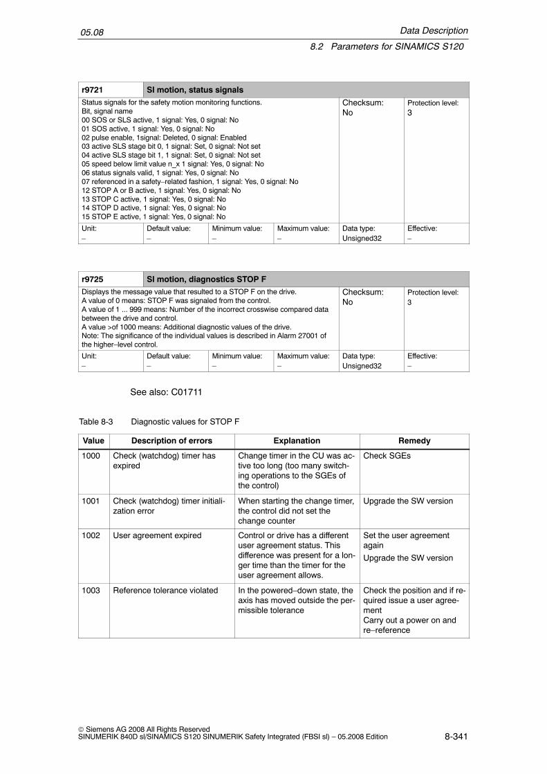
Data Description
8.2 Parameters for SINAMICS S120
05.08
8-341© Siemens AG 2008 All Rights ReservedSINUMERIK 840D sl/SINAMICS S120 SINUMERIK Safety Integrated (FBSI sl) – 05.2008 Edition
r9721 SI motion, status signalsStatus signals for the safety motion monitoring functions.Bit, signal name00 SOS or SLS active, 1 signal: Yes, 0 signal: No01 SOS active, 1 signal: Yes, 0 signal: No02 pulse enable, 1signal: Deleted, 0 signal: Enabled03 active SLS stage bit 0, 1 signal: Set, 0 signal: Not set04 active SLS stage bit 1, 1 signal: Set, 0 signal: Not set05 speed below limit value n_x 1 signal: Yes, 0 signal: No06 status signals valid, 1 signal: Yes, 0 signal: No07 referenced in a safety–related fashion, 1 signal: Yes, 0 signal: No12 STOP A or B active, 1 signal: Yes, 0 signal: No13 STOP C active, 1 signal: Yes, 0 signal: No14 STOP D active, 1 signal: Yes, 0 signal: No15 STOP E active, 1 signal: Yes, 0 signal: No
Checksum:No
Protection level:3
Unit:–
Default value:–
Minimum value:–
Maximum value:–
Data type:Unsigned32
Effective:–
r9725 SI motion, diagnostics STOP FDisplays the message value that resulted to a STOP F on the drive.A value of 0 means: STOP F was signaled from the control.A value of 1 ... 999 means: Number of the incorrect crosswise compared databetween the drive and control.A value >of 1000 means: Additional diagnostic values of the drive.Note: The significance of the individual values is described in Alarm 27001 ofthe higher–level control.
Checksum:No
Protection level:3
Unit:–
Default value:–
Minimum value:–
Maximum value:–
Data type:Unsigned32
Effective:–
See also: C01711
Table 8-3 Diagnostic values for STOP F
Value Description of errors Explanation Remedy
1000 Check (watchdog) timer hasexpired
Change timer in the CU was ac-tive too long (too many switch-ing operations to the SGEs ofthe control)
Check SGEs
1001 Check (watchdog) timer initiali-zation error
When starting the change timer,the control did not set thechange counter
Upgrade the SW version
1002 User agreement expired Control or drive has a differentuser agreement status. Thisdifference was present for a lon-ger time than the timer for theuser agreement allows.
Set the user agreementagain
Upgrade the SW version
1003 Reference tolerance violated In the powered–down state, theaxis has moved outside the per-missible tolerance
Check the position and if re-quired issue a user agree-mentCarry out a power on andre–reference

Data Description
8.2 Parameters for SINAMICS S120
05.08
8-342© Siemens AG 2008 All Rights Reserved
SINUMERIK 840D sl/SINAMICS S120 SINUMERIK Safety Integrated (FBSI sl) – 05.2008 Edition
Table 8-3 Diagnostic values for STOP F
Value RemedyExplanationDescription of errors
1004 Violated plausibility, user agree-ment
The value in p9726 violates theinternal value for the useragreement
Reference the axis if thishas not already been done
1005 Select test stop if the pulseshave already been cancelled
It does not make sense to se-lect a test stop if the pulses arealready cancelled
Wait until the pulses havebeen enabled and thenagain initiate a test stop
1006 Reserved – –
1007 Communications failure be-tween the PLC and drive
Sign of life failure in SGE/SGAbetween the PLC and drive
Check communications be-tween the drive and controlor NCK and PLC (SPL)
1008 Data transfer error between thePLC and drive
CRC error in SGE or SGA Check communications be-tween the drive and controlor NCK and PLC (SPL)
1011 Acceptance test status different The acceptance test status be-tween the drive and control isdifferent.
End the acceptance testmode and select again
1012 Plausibility violation of the ac-tual value for the control
The redundant coarse positiondoes not match the actualvalue.
Upgrade Sensor ModuleSWReplace the Sensor Module
1016 Telegram has failed three timeswith the same crosswise datacomparison data
In the crosswise comparisonclock cycle (= monitoring clockcycle * number of crosswisecomparison data) the compari-son of the same list data wasmissed three times in a row dueto telegram failures.
Check communications be-tween the drive and control
1020 Telegram has failed twice An incorrect sign of life wasidentified in the safety data twotimes in a row.
Check communicationsbetween the drive and con-trol
1021 Sign of life error in the commu-nications with the Sensor Mod-ule
Communications failure with theSensor Module was identifiedtwo times in a row.
Check communications be-tween the Sensor Moduleand the drive
p9726 SI motion, user agreement, select/deselectSetting to select/deselect the user agreement0: [00 hex] Deselect user agreement172: [AC hex] Select user agreement
Checksum:No
Protection level:4
Unit:–
Default value:0000 hex
Minimum value:0000 hex
Maximum value:00AC hex
Data type:Integer16
Effective:POWER ON

Data Description
8.2 Parameters for SINAMICS S120
05.08
8-343© Siemens AG 2008 All Rights ReservedSINUMERIK 840D sl/SINAMICS S120 SINUMERIK Safety Integrated (FBSI sl) – 05.2008 Edition
r9727 SI motion, internal drive user agreementDisplays the internal status of the user agreementValue = 0: User agreement is not setValue = AC hex: User agreement is set
Checksum:No
Protection level:4
Unit:–
Default value:–
Minimum value:–
Maximum value:–
Data type:Integer16
Effective:
r9728[0...1] SI motion, actual checksum, SI parametersDisplays the checksum over the checked Safety Integrated parameters of themotion monitoring functions (actual checksum).[0]: Checksum over SI parameters for motion monitoring[1]: Checksum over SI parameters for actual values
Checksum:No
Protection level:3
Unit:–
Default value:–
Minimum value:–
Maximum value:–
Data type:Unsigned32
Effective:
See also: F01680 ”SI motion: Checksum error safe monitoring functions”.
r9729[0...1] SI motion, reference checksum, SI parametersSets the checksum over the checked Safety Integrated parameters of the mo-tion monitoring functions (reference checksum).[0]: Checksum over SI parameters for motion monitoring[1]: Checksum over SI parameters for actual valuesSee also: r9728
Checksum:No
Protection level:3
Unit:–
Default value:0000 hex
Minimum value:0000 hex
Maximum value:0xFFFF FFFF
Data type:Unsigned32
Effective:POWER ON
See also: F01680 ”SI motion: Checksum error safe monitoring functions”.

Data Description
8.2 Parameters for SINAMICS S120
05.08
8-344© Siemens AG 2008 All Rights Reserved
SINUMERIK 840D sl/SINAMICS S120 SINUMERIK Safety Integrated (FBSI sl) – 05.2008 Edition
r9735[0...1] SI motion, diagnostics result list 3Displays result list 3 where for a crosswise data comparison with the control,led to an error.[0]: Result list second channel[1]: Result list driveBit fieldBit 00 Actual value > Upper limit SN1+Bit 01 Actual value > Lower limit SN1+Bit 02 Actual value > Upper limit SN1–Bit 03 Actual value > Lower limit SN1–Bit 04 Actual value > Upper limit SN2+Bit 05 Actual value > Lower limit SN2+Bit 06 Actual value > Upper limit SN2–Bit 07 Actual value > Lower limit SN2–Bit 08 Actual value > Upper limit SN3+Bit 09 Actual value > Lower limit SN3+Bit 10 Actual value > Upper limit SN3–Bit 11 Actual value > Lower limit SN3–Bit 12 Actual value > Upper limit SN4+Bit 13 Actual value > Lower limit SN4+Bit 14 Actual value > Upper limit SN4–Bit 15 Actual value > Lower limit SN4–Bit 16 Actual value > Upper limit SN5+Bit 17 Actual value > Lower limit SN5+Bit 18 Actual value > Upper limit SN5–Bit 19 Actual value > Lower limit SN5–Bit 20 Actual value > Upper limit SN6+Bit 21 Actual value > Lower limit SN6+Bit22 Actual value > Upper limit SN6–Bit23 Actual value > Lower limit SN6–See also: C01711
Checksum:Yes
Protection level:3
Unit:–
Default value:–
Minimum value:–
Maximum value:–
Data type:Unsigned32
Effective:POWER ON

Data Description
8.2 Parameters for SINAMICS S120
05.08
8-345© Siemens AG 2008 All Rights ReservedSINUMERIK 840D sl/SINAMICS S120 SINUMERIK Safety Integrated (FBSI sl) – 05.2008 Edition
r9736[0...1] SI motion, diagnostics result list 4Displays result list 4 where for a crosswise data comparison with the control,led to an error.[0]: Result list second channel[1]: Result list driveBit fieldBit 00 Actual value > Upper limit SN7+Bit 01 Actual value > Lower limit SN7+Bit 02 Actual value > Upper limit SN7–Bit 03 Actual value > Lower limit SN7–Bit 04 Actual value > Upper limit SN8+Bit 05 Actual value > Lower limit SN8+Bit 06 Actual value > Upper limit SN8–Bit 07 Actual value > Lower limit SN8–Bit 08 Actual value > Upper limit SN9+Bit 09 Actual value > Lower limit SN9+Bit 10 Actual value > Upper limit SN9–Bit 11 Actual value > Lower limit SN9–Bit 12 Actual value > Upper limit SN10+Bit 13 Actual value > Lower limit SN10+Bit 14 Actual value > Upper limit SN10–Bit 15 Actual value > Lower limit SN10–Bit 16 Actual value > Upper limit SN11+Bit 17 Actual value > Lower limit SN11+Bit 18 Actual value > Upper limit SN11–Bit 19 Actual value > Lower limit SN11–Bit 20 Actual value > Upper limit SN12+Bit 21 Actual value > Lower limit SN12+Bit22 Actual value > Upper limit SN12–Bit23 Actual value > Lower limit SN12–See also: C01711
Checksum:Yes
Protection level:3
Unit:–
Default value:–
Minimum value:–
Maximum value:–
Data type:Unsigned32
Effective:POWER ON

Data Description
8.2 Parameters for SINAMICS S120
05.08
8-346© Siemens AG 2008 All Rights Reserved
SINUMERIK 840D sl/SINAMICS S120 SINUMERIK Safety Integrated (FBSI sl) – 05.2008 Edition
r9737[0...1] SI motion, diagnostics result list 5Displays result list 5 where for a crosswise data comparison with the control,led to an error.[0]: Result list second channel[1]: Result list driveBit fieldBit 00 Actual value > Upper limit SN13+Bit 01 Actual value > Lower limit SN13+Bit 02 Actual value > Upper limit SN13–Bit 03 Actual value > Lower limit SN13–Bit 04 Actual value > Upper limit SN14+Bit 05 Actual value > Lower limit SN14+Bit 06 Actual value > Upper limit SN14–Bit 07 Actual value > Lower limit SN14–Bit 08 Actual value > Upper limit SN15+Bit 09 Actual value > Lower limit SN15+Bit 10 Actual value > Upper limit SN15–Bit 11 Actual value > Lower limit SN15–Bit 12 Actual value > Upper limit SN16+Bit 13 Actual value > Lower limit SN16+Bit 14 Actual value > Upper limit SN16–Bit 15 Actual value > Lower limit SN16–Bit 16 Actual value > Upper limit SN17+Bit 17 Actual value > Lower limit SN17+Bit 18 Actual value > Upper limit SN17–Bit 19 Actual value > Lower limit SN17–Bit 20 Actual value > Upper limit SN18+Bit 21 Actual value > Lower limit SN18+Bit22 Actual value > Upper limit SN18–Bit23 Actual value > Lower limit SN18–See also: C01711
Checksum:Yes
Protection level:3
Unit:–
Default value:–
Minimum value:–
Maximum value:–
Data type:Unsigned32
Effective:POWER ON

Data Description
8.2 Parameters for SINAMICS S120
05.08
8-347© Siemens AG 2008 All Rights ReservedSINUMERIK 840D sl/SINAMICS S120 SINUMERIK Safety Integrated (FBSI sl) – 05.2008 Edition
r9738[0...1] SI motion, diagnostics result list 6Displays result list 6 where for a crosswise data comparison with the control,led to an error.[0]: Result list second channel[1]: Result list driveBit fieldBit 00 Actual value > Upper limit SN19+Bit 01 Actual value > Lower limit SN19+Bit 02 Actual value > Upper limit SN19–Bit 03 Actual value > Lower limit SN19–Bit 04 Actual value > Upper limit SN20+Bit 05 Actual value > Lower limit SN20+Bit 06 Actual value > Upper limit SN20–Bit 07 Actual value > Lower limit SN20–Bit 08 Actual value > Upper limit SN21+Bit 09 Actual value > Lower limit SN21+Bit 10 Actual value > Upper limit SN21–Bit 11 Actual value > Lower limit SN21–Bit 12 Actual value > Upper limit SN22+Bit 13 Actual value > Lower limit SN22+Bit 14 Actual value > Upper limit SN22–Bit 15 Actual value > Lower limit SN22–Bit 16 Actual value > Upper limit SN23+Bit 17 Actual value > Lower limit SN23+Bit 18 Actual value > Upper limit SN23–Bit 19 Actual value > Lower limit SN23–Bit 20 Actual value > Upper limit SN24+Bit 21 Actual value > Lower limit SN24+Bit22 Actual value > Upper limit SN24–Bit23 Actual value > Lower limit SN24–See also: C01711
Checksum:Yes
Protection level:3
Unit:–
Default value:–
Minimum value:–
Maximum value:–
Data type:Unsigned32
Effective:POWER ON

Data Description
8.2 Parameters for SINAMICS S120
05.08
8-348© Siemens AG 2008 All Rights Reserved
SINUMERIK 840D sl/SINAMICS S120 SINUMERIK Safety Integrated (FBSI sl) – 05.2008 Edition
r9739[0...1] SI motion, diagnostics result list 7Displays result list 7 where for a crosswise data comparison with the control,led to an error.[0]: Result list second channel[1]: Result list driveBit fieldBit 00 Actual value > Upper limit SN25+Bit 01 Actual value > Lower limit SN25+Bit 02 Actual value > Upper limit SN25–Bit 03 Actual value > Lower limit SN25–Bit 04 Actual value > Upper limit SN26+Bit 05 Actual value > Lower limit SN26+Bit 06 Actual value > Upper limit SN26–Bit 07 Actual value > Lower limit SN26–Bit 08 Actual value > Upper limit SN27+Bit 09 Actual value > Lower limit SN27+Bit 10 Actual value > Upper limit SN27–Bit 11 Actual value > Lower limit SN27–Bit 12 Actual value > Upper limit SN28+Bit 13 Actual value > Lower limit SN28+Bit 14 Actual value > Upper limit SN28–Bit 15 Actual value > Lower limit SN28–Bit 16 Actual value > Upper limit SN29+Bit 17 Actual value > Lower limit SN29+Bit 18 Actual value > Upper limit SN29–Bit 19 Actual value > Lower limit SN29–Bit 20 Actual value > Upper limit SN30+Bit 21 Actual value > Lower limit SN30+Bit22 Actual value > Upper limit SN30–Bit23 Actual value > Lower limit SN30–See also: C01711
Checksum:Yes
Protection level:3
Unit:–
Default value:–
Minimum value:–
Maximum value:–
Data type:Unsigned32
Effective:POWER ON
r9744 SI message buffer changes, counterDisplays the changes of the safety message buffer. This counter is increm-ented every time that the safety message buffer changes.This is used to check whether the safety message buffer has been read outconsistently.See also r9747, r9748, r9749, p9752, r9754, r9755, r9756, r9759
Checksum:–
Protection level:3
Unit:–
Default value:–
Minimum value:–
Maximum value:–
Data type:Unsigned16
Effective:–
r9747[0...63] SI message codeDisplays the number of the safety messages that have occurred.See also r9744, r9748, r9749, r9754, p9752, r9753, r9754, r9755, r9756, r9759
Checksum:–
Protection level:3
Unit:–
Default value:–
Minimum value:–
Maximum value:–
Data type:Unsigned16
Effective:–

Data Description
8.2 Parameters for SINAMICS S120
05.08
8-349© Siemens AG 2008 All Rights ReservedSINUMERIK 840D sl/SINAMICS S120 SINUMERIK Safety Integrated (FBSI sl) – 05.2008 Edition
r9748[0...63] SI message time received in millisecondsDisplays the relative system runtime in milliseconds when the safety messageoccurred.See also r9744, r9747, r9749, p9752, r9753, r9754, r9755, r9756, p9759
Checksum:–
Protection level:3
Unit:ms
Default value:–
Minimum value:–
Maximum value:–
Data type:Unsigned32
Effective:–
r9749[0...63] SI message valueDisplays the additional information about the safety message that occurred (asinteger number).See also r9744, r9747, r9748, p9752, r9753, r9754, r9755, r9756, p9759
Checksum:–
Protection level:3
Unit:–
Default value:–
Minimum value:–
Maximum value:–
Data type:Integer32
Effective:–
p9752 SI message cases, counterNumber of safety message cases that have occurred since the last reset. Thesafety message buffer is cleared by resetting the parameter to 0.See also r9745, r9748, r9749, r9754, r9755, r9756
Checksum:–
Protection level:3
Unit:–
Default value:0
Minimum value:0
Maximum value:65535
Data type:Unsigned16
Effective:POWER ON
r9753[0...63] SI message value for float valuesDisplays additional information about the safety message that has occurred forfloat values.See also r9744, r9747, r9748, p9752, r9754, r9755, r9756, p9759
Checksum:–
Protection level:3
Unit:–
Default value:–
Minimum value:–
Maximum value:–
Data type:Floating point
Effective:–
r9754[0...63] SI message time received in daysDisplays the relative system runtime in days when the safety message oc-curred.See also r9744, r9747, r9748, r7949, p9752, r9753, r9755, r9756, p9759
Checksum:–
Protection level:3
Unit:days
Default value:–
Minimum value:–
Maximum value:–
Data type:Unsigned16
Effective:–
r9755[0...63] SI message time removed in millisecondsDisplays the relative system runtime in milliseconds when the safety messagewas removed.See also r9744, r9747, r9748, r7949, p9752, r9753, r9754, r9756, p9759
Checksum:–
Protection level:3
Unit:ms
Default value:–
Minimum value:–
Maximum value:–
Data type:Unsigned32
Effective:–

Data Description
8.2 Parameters for SINAMICS S120
05.08
8-350© Siemens AG 2008 All Rights Reserved
SINUMERIK 840D sl/SINAMICS S120 SINUMERIK Safety Integrated (FBSI sl) – 05.2008 Edition
r9756[0...63] SI message time removed in daysDisplays the relative system runtime in days when the safety message wasremoved.See also r9744, r9747, r9748, r7949, p9752, r9753,r9754, r9755, p9759
Checksum:–
Protection level:3
Unit:days
Default value:–
Minimum value:–
Maximum value:–
Data type:Unsigned16
Effective:–
p9759 SI acknowledge messages, drive objectAcknowledges all safety messages present for a drive object.Parameter should be set from 0 to 1 to acknowledge. After acknowledgement,the parameter is automatically reset to 0.See also r9744, r9747, r9748, r7949, p9752, r9753,r9754, r9755, p9759
Checksum:–
Protection level:3
Unit:–
Default value:0
Minimum value:0
Maximum value:1
Data type:Unsigned8
Effective:–
p9761 SI password inputEnters the Safety Integrated password. It is not permissible to change SafetyIntegrated parameter settings until the Safety Integrated password has beenentered.
Checksum:No
Protection level:3
Unit:–
Default value:0000 hex
Minimum value:0000 hex
Maximum value:FFFF FFFF hex
Data type:Unsigned32
Effective:Immediately
See also: F01659 ”SI CU: Write task for parameter rejected”
p9762 SI password, newEnters a new Safety Integrated password. If the Safety Integrated password ischanged it must be acknowledged in the following parameter:See also: p9763
Checksum:No
Protection level:3
Unit:–
Default value:0000 hex
Minimum value:0000 hex
Maximum value:FFFF FFFF hex
Data type:Unsigned32
Effective:Immediately
p9763 SI password acknowledgmentAcknowledges the new Safety Integrated password. The new password en-tered into p9762 must be re–entered in order to acknowledge. After success-fully acknowledged, the new Safety Integrated password is set withp9762=p9763=0.See also: p9762
Checksum:No
Protection level:3
Unit:–
Default value:0000 hex
Minimum value:0000 hex
Maximum value:FFFF FFFF hex
Data type:Unsigned32
Effective:Immediately
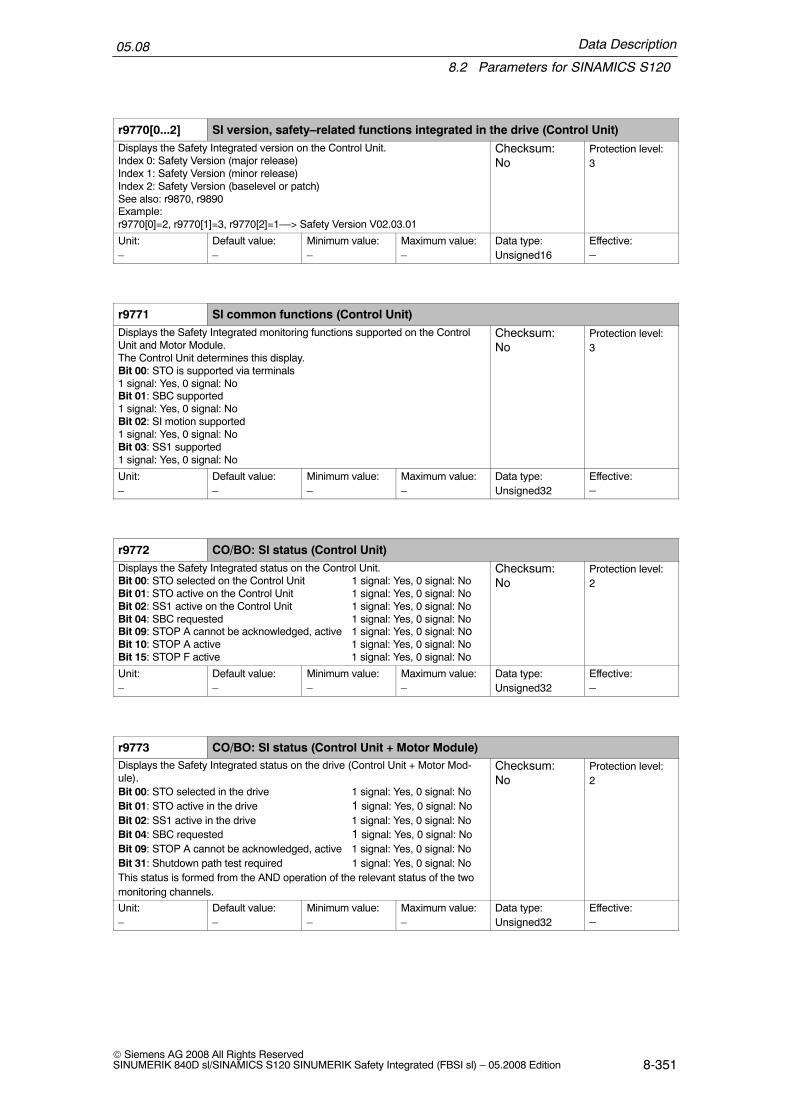
Data Description
8.2 Parameters for SINAMICS S120
05.08
8-351© Siemens AG 2008 All Rights ReservedSINUMERIK 840D sl/SINAMICS S120 SINUMERIK Safety Integrated (FBSI sl) – 05.2008 Edition
r9770[0...2] SI version, safety–related functions integrated in the drive (Control Unit)Displays the Safety Integrated version on the Control Unit.Index 0: Safety Version (major release)Index 1: Safety Version (minor release)Index 2: Safety Version (baselevel or patch)See also: r9870, r9890Example:r9770[0]=2, r9770[1]=3, r9770[2]=1––> Safety Version V02.03.01
Checksum:No
Protection level:3
Unit:–
Default value:–
Minimum value:–
Maximum value:–
Data type:Unsigned16
Effective:–
r9771 SI common functions (Control Unit)Displays the Safety Integrated monitoring functions supported on the ControlUnit and Motor Module.The Control Unit determines this display.Bit 00: STO is supported via terminals1 signal: Yes, 0 signal: NoBit 01: SBC supported1 signal: Yes, 0 signal: NoBit 02: SI motion supported1 signal: Yes, 0 signal: NoBit 03: SS1 supported1 signal: Yes, 0 signal: No
Checksum:No
Protection level:3
Unit:–
Default value:–
Minimum value:–
Maximum value:–
Data type:Unsigned32
Effective:–
r9772 CO/BO: SI status (Control Unit)Displays the Safety Integrated status on the Control Unit.Bit 00: STO selected on the Control Unit 1 signal: Yes, 0 signal: NoBit 01: STO active on the Control Unit 1 signal: Yes, 0 signal: NoBit 02: SS1 active on the Control Unit 1 signal: Yes, 0 signal: NoBit 04: SBC requested 1 signal: Yes, 0 signal: NoBit 09: STOP A cannot be acknowledged, active 1 signal: Yes, 0 signal: NoBit 10: STOP A active 1 signal: Yes, 0 signal: NoBit 15: STOP F active 1 signal: Yes, 0 signal: No
Checksum:No
Protection level:2
Unit:–
Default value:–
Minimum value:–
Maximum value:–
Data type:Unsigned32
Effective:–
r9773 CO/BO: SI status (Control Unit + Motor Module)Displays the Safety Integrated status on the drive (Control Unit + Motor Mod-ule).Bit 00: STO selected in the drive 1 signal: Yes, 0 signal: NoBit 01: STO active in the drive 1 signal: Yes, 0 signal: NoBit 02: SS1 active in the drive 1 signal: Yes, 0 signal: NoBit 04: SBC requested 1 signal: Yes, 0 signal: NoBit 09: STOP A cannot be acknowledged, active 1 signal: Yes, 0 signal: NoBit 31: Shutdown path test required 1 signal: Yes, 0 signal: NoThis status is formed from the AND operation of the relevant status of the twomonitoring channels.
Checksum:No
Protection level:2
Unit:–
Default value:–
Minimum value:–
Maximum value:–
Data type:Unsigned32
Effective:–
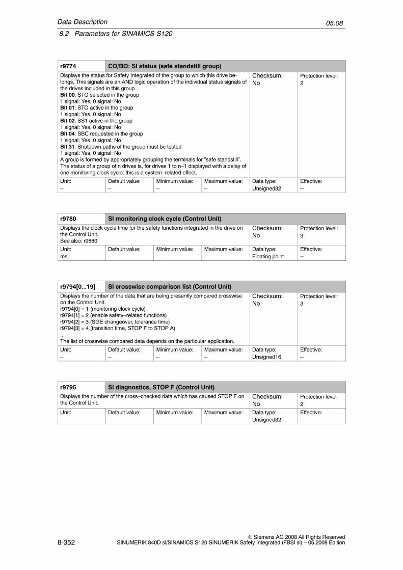
Data Description
8.2 Parameters for SINAMICS S120
05.08
8-352© Siemens AG 2008 All Rights Reserved
SINUMERIK 840D sl/SINAMICS S120 SINUMERIK Safety Integrated (FBSI sl) – 05.2008 Edition
r9774 CO/BO: SI status (safe standstill group)Displays the status for Safety Integrated of the group to which this drive be-longs. This signals are an AND logic operation of the individual status signals ofthe drives included in this groupBit 00: STO selected in the group1 signal: Yes, 0 signal: NoBit 01: STO active in the group1 signal: Yes, 0 signal: NoBit 02: SS1 active in the group1 signal: Yes, 0 signal: NoBit 04: SBC requested in the group1 signal: Yes, 0 signal: NoBit 31: Shutdown paths of the group must be tested1 signal: Yes, 0 signal: NoA group is formed by appropriately grouping the terminals for ”safe standstill”.The status of a group of n drives is, for drives 1 to n–1 displayed with a delay ofone monitoring clock cycle; this is a system–related effect.
Checksum:No
Protection level:2
Unit:–
Default value:–
Minimum value:–
Maximum value:–
Data type:Unsigned32
Effective:–
r9780 SI monitoring clock cycle (Control Unit)Displays the clock cycle time for the safety functions integrated in the drive onthe Control Unit.See also: r9880
Checksum:No
Protection level:3
Unit:ms
Default value:–
Minimum value:–
Maximum value:–
Data type:Floating point
Effective:–
r9794[0...19] SI crosswise comparison list (Control Unit)Displays the number of the data that are being presently compared crosswiseon the Control Unit.r9794[0] = 1 (monitoring clock cycle)r9794[1] = 2 (enable safety–related functions)r9794[2] = 3 (SGE changeover, tolerance time)r9794[3] = 4 (transition time, STOP F to STOP A)...The list of crosswise compared data depends on the particular application.
Checksum:No
Protection level:3
Unit:–
Default value:–
Minimum value:–
Maximum value:–
Data type:Unsigned16
Effective:–
r9795 SI diagnostics, STOP F (Control Unit)Displays the number of the cross–checked data which has caused STOP F onthe Control Unit.
Checksum:No
Protection level:2
Unit:–
Default value:–
Minimum value:–
Maximum value:–
Data type:Unsigned32
Effective:–

Data Description
8.2 Parameters for SINAMICS S120
05.08
8-353© Siemens AG 2008 All Rights ReservedSINUMERIK 840D sl/SINAMICS S120 SINUMERIK Safety Integrated (FBSI sl) – 05.2008 Edition
Cross-wisedata
compari-son ID
Crosswise comparison data Associated parameters
1 SI monitoring clock cycle, integrated in the drive r9780
2 SI enable parameters (CU/MM) p9601/p9801
3 Tolerance time changeover, safety–related input signals(CU/MM)
p9650/p9850
4 Transition time from STOP F to STOP A (CU/MM) p9658/p9858
5 Safe brake control (CU/MM) p9602/p9802
6 Enable, safe motion monitoring p9501/p29822
Additional diagnostic values (from 1000 onwards):
Value Description of errors Explanation
1000 Check (watchdog) timer has expired Change timer in the MM has been active too long
1001 Change timer initialization error When starting the change timer, MM has not setthe ”timer running bit”
1002 Check (watchdog) timer initialization error The CU had not started the check (watchdog)timer although in MM the change timer is presentlyrunning
2000 Error when comparing the SH terminals Status of the SH terminals on the Control Unit andMotor Module are different.
2001 Error when comparing the feedback signalsDIAG_U and DIAG_L
Status of the feedback signals of the safety shut-down paths on the Control Unit and Motor Moduleare different.
r9798 SI actual checksum SI parameters (Control Unit)Displays the checksum over the checked Safety Integrated parameters on theControl Unit (actual checksum).
Checksum:No
Protection level:3
Unit:–
Default value:–
Minimum value:–
Maximum value:–
Data type:Unsigned32
Effective:–
r9799 SI reference checksum SI parameters (Control Unit)Sets the checksum for the checked Safety Integrated parameters on the Con-trol Unit (reference checksum).
Checksum:No
Protection level:3
Unit:–
Default value:0000 hex
Minimum value:0000 hex
Maximum value:FFFF FFFF hex
Data type:Unsigned32
Effective:
The actual checksum (r9798) calculated by the CU must be entered into the refer-ence checksum p9799. This therefore acknowledges the safety commissioning onthe Control Unit.

Data Description
8.2 Parameters for SINAMICS S120
05.08
8-354© Siemens AG 2008 All Rights Reserved
SINUMERIK 840D sl/SINAMICS S120 SINUMERIK Safety Integrated (FBSI sl) – 05.2008 Edition
Parameters for functions integrated in the drive MM
p9801 SI enable safety functions (Motor Module)Sets the enable signals for safety functions on the Motor ModuleBit 00: STO enabled via terminals (Motor Module)1 signal: Enabled, 0 signal: Locks
Checksum:Yes
Protection level:3
Unit:–
Default value:0
Minimum value:0
Maximum value:1h
Data type:Unsigned16
Effective:
It is permissible to simultaneously enable the safety functions integrated in thedrive (p9601/p9801 < > 0) and the motion monitoring functions (p9501 < > 0).
p9802 SI enable safe brake control (Motor Module)Sets the enable signal for the ”Safe brake control” function (SBC) on the MotorModule.0: SBC not enabled1: Close the holding brake when SH is selected or when SI errors occurThe ”safe brake control” function only becomes active if at least one safetymonitoring function is enabled (i.e. p9501 not equal to 0 and/or p9801 not equalto 0).If a motor holding brake is not being used then it does not make any sense toenable the parameterization ”no motor holding brake available” and ”safe brakecontrol” (p1215 = 0, p9602 = p9802 = 1).The parameterization ”motor holding brake the same as sequence control,connection via BICO” and ”safe brake control” enabled (p1215 = 3, p9602 = 1,p9802 = 1) does not make sense.The parameterization ”motor holding brake without feedback signals” and ”safebrake control” enabled (p1278 = 1, p9602 = 1, p9802 = 1) is not permissible.
Checksum:Yes
Protection level:3
Unit:–
Default value:0
Minimum value:0
Maximum value:1
Data type:Integer32
Effective:
If p9802 = 1, the holding braking is closed when SH is selected or SI errors occur.p9602 has priority over p1215.
p9810 SI PROFIsafe address (Motor Module)Sets the PROFIsafe address of the Motor Module. Checksum:
YesProtection level:3
Unit:–
Default value:0000 hex
Minimum value:0000 hex
Maximum value:FFFF hex
Data type:Unsigned16
Effective:

Data Description
8.2 Parameters for SINAMICS S120
05.08
8-355© Siemens AG 2008 All Rights ReservedSINUMERIK 840D sl/SINAMICS S120 SINUMERIK Safety Integrated (FBSI sl) – 05.2008 Edition
p9850 SI SGE changeover, tolerance time (Motor Module)Sets the tolerance time to changeover the safety–related inputs (SGE) on theMotor Module. Because of the different runtimes of the two monitoring chan-nels, an SIS switchover is not effective at the same time. After an SIS switch-over, a cross–comparison of the dynamic data is not carried out during thistolerance time.For a crosswise data comparison between p9650 and p9850, a difference ofone safety monitoring clock cycle is tolerated.The parameterized time is internally rounded–off to an integer multiple of themonitoring clock cycle.
Checksum:Yes
Protection level:3
Unit:�s
Default value:500 000
Minimum value:0
Maximum value:2 000 000
Data type:Floating point
Effective:
p9852 SI Safe Stop 1 delay time (Motor Module)Sets the delay time of the pulse cancellation for the function ”Safe Stop 1”(SS1) on the Motor Module to brake along the OFF3 down ramp (p1135).Also refer to: p1135, p9652For a crosswise data comparison between p9652 and p9852, a difference ofone safety monitoring clock cycle is tolerated.The parameterized time is internally rounded–off to an integer multiple of themonitoring clock cycle.
Checksum:Yes
Protection level:3
Unit:ms
Default value:0
Minimum value:0
Maximum value:300000.00
Data type:Floating point
Effective:
p9858 SI transition time STOP F to STOP A (Motor Module)Sets the transition time from STOP F to STOP A on the Motor Module.For a crosswise data comparison between p9658 and p9858, a difference ofone safety monitoring clock cycle is tolerated.The parameterized time is internally rounded–off to an integer multiple of themonitoring clock cycle.STOP F: Defect in a monitoring channel (error in the crosswise data compari-son)STOP A: Pulse deletion via safety shutdown path
Checksum:Yes
Protection level:3
Unit:�s
Default value:0
Minimum value:0
Maximum value:30 000 000.00
Data type:Floating point
Effective:
r9870[0...2] SI version, safety functions integrated in the drive (Motor Module)Displays the Safety Integrated version on the Motor Module.[0]: Safety Version (major release)[1]: Safety Version (minor release)[2]: Safety Version (baselevel or patch)Example:r9870[0]=2, r9870[1]=3, r9870[2]=1––> Safety Version V02.03.01
Checksum:No
Protection level:3
Unit:–
Default value:–
Minimum value:–
Maximum value:–
Data type:Unsigned16
Effective:–

Data Description
8.2 Parameters for SINAMICS S120
05.08
8-356© Siemens AG 2008 All Rights Reserved
SINUMERIK 840D sl/SINAMICS S120 SINUMERIK Safety Integrated (FBSI sl) – 05.2008 Edition
r9871 SI common functions (Motor Module)Displays the Safety Integrated monitoring functions supported on the ControlUnit and Motor Module.The Motor Module determines this display.Bit 00: SH supported via terminal1 signal: Yes, 0 signal: NoBit 01: SBC is supported1 signal: Yes, 0 signal: NoBit 02: SI motion supported1 signal: Yes, 0 signal: NoBit 03: SS1 supported1 signal: Yes, 0 signal: No
Checksum:No
Protection level:3
Unit:–
Default value:–
Minimum value:–
Maximum value:–
Data type:Unsigned32
Effective:–
r9872 CO/BO: SI status (Motor Module)Displays the Safety Integrated status on the Motor Module.Bit 00: SH selected on the Motor Module1 signal: Yes, 0 signal: NoBit 01: SH active on the Motor Module1 signal: Yes, 0 signal: NoBit 02: SS1 active on the Motor Module1 signal: Yes, 0 signal: NoBit 04: SBC requested1 signal: Yes, 0 signal: NoBit 09: STOP A cannot be acknowl., active1 signal: Yes, 0 signal: NoBit 10: STOP A active1 signal: Yes, 0 signal: NoBit 15: STOP F active1 signal: Yes, 0 signal: No
Checksum:No
Protection level:2
Unit:–
Default value:–
Minimum value:–
Maximum value:–
Data type:Unsigned32
Effective:–
r9880 SI monitoring clock cycle (Motor Module)Displays the clock cycle time for the Safety Integrated Basic Functions on theMotor Module.
Checksum:No
Protection level:3
Unit:ms
Default value:–
Minimum value:–
Maximum value:–
Data type:Floating point
Effective:–
r9881[0...11] SI motion Sensor Module Node Identifier, second channelDisplays the Node Identifier of the Sensor Module that is used by the secondchannel for the motion monitoring functions.
Checksum:No
Protection level:4
Unit:–
Default value:–
Minimum value:–
Maximum value:–
Data type:Unsigned8
Effective:–

Data Description
8.2 Parameters for SINAMICS S120
05.08
8-357© Siemens AG 2008 All Rights ReservedSINUMERIK 840D sl/SINAMICS S120 SINUMERIK Safety Integrated (FBSI sl) – 05.2008 Edition
r9890[0...2] SI version (Sensor Module)Displays the Safety Integrated version on the Sensor Module.[0]: Safety Version (major release)[1]: Safety Version (minor release)[2]: Safety Version (baselevel or patch)Example:r9890[0]=2, r9890[1]=3, r9890[2]=1––> Safety Version V02.03.01
Checksum:No
Protection level:3
Unit:–
Default value:–
Minimum value:–
Maximum value:–
Data type:Unsigned16
Effective:–
r9894[0...19] SI crosswise comparison list (Motor Module)Displays the number of the data that are being presently compared crosswiseon the Motor Module.Example:r9894[0] = 1 (monitoring clock cycle)r9894[1] = 2 (enable safety–related functions)r9894[2] = 3 (SGE changeover, tolerance time)r9894[3] = 4 (transition time, STOP F to STOP A)...The list of crosswise compared data depends on the particular application.
Checksum:No
Protection level:2
Unit:–
Default value:–
Minimum value:–
Maximum value:–
Data type:Unsigned16
Effective:–
r9895 SI diagnostics, STOP F (Motor Module)Displays the number of the cross–checked data which has caused STOP F onthe Motor Module.
Checksum:No
Protection level:2
Unit:–
Default value:–
Minimum value:–
Maximum value:–
Data type:Unsigned32
Effective:–
Diagnostics data that provides more information on Fault F30611 (”SI MM: Defectin a monitoring channel”).
Cross-wisedata
compari-son ID
Crosswise comparison data Associated parameters
1 SI monitoring clock cycle r9780, r9880
2 SI enable safety functions p9601, p9801
3 SI SGE changeover, tolerance time p9650, p9850
4 SI transition time from STOP F to STOP A p9658, p9858
5 SI enable safe brake control p9602, p9802
6 SI motion, enable safety–related functions p9501, p2982
7 SI delay time of the pulse cancellation for Safe Stop 1 p9652, p9852
8 SI PROFIsafe address p9610, p9810
Additional diagnostic values (from 1000 onwards):

Data Description
8.2 Parameters for SINAMICS S120
05.08
8-358© Siemens AG 2008 All Rights Reserved
SINUMERIK 840D sl/SINAMICS S120 SINUMERIK Safety Integrated (FBSI sl) – 05.2008 Edition
Value Description of errors Explanation
1000 Check (watchdog) timer has expired Change timer in the CU has been active too long
1001 Change timer initialization error When starting the change timer, the CU had notset the ”timer running bit”
1002 Check (watchdog) timer initialization error The MM had not started the check (watchdog)timer although the change timer is currently run-ning in the CU
2000 Error when comparing the SH terminals Status of the SH terminals on the Control Unit andMotor Module are different.
2001 Error when comparing the feedback signalsDIAG_U and DIAG_L
Status of the feedback signals of the safety shut-down paths on the Control Unit and Motor Moduleare different.
2002 Error when comparing the feedback signals Status of the delay timer SS1 on the Control Unitand Motor Module are different
r9898 SI actual checksum SI parameters (Motor Module)Displays the checksum for the checked Safety Integrated parameters on theMotor Module (actual checksum).
Checksum:No
Protection level:3
Unit:–
Default value:–
Minimum value:–
Maximum value:–
Data type:Unsigned32
Effective:–
r9899 SI reference checksum SI parameters (Motor Module)Sets the checksum for the checked Safety Integrated parameters on the MotorModule (reference checksum).
Checksum:No
Protection level:3
Unit:–
Default value:0000 hex
Minimum value:0000 hex
Maximum value:FFFF FFFF hex
Data type:Unsigned32
Effective:When exiting theSI commissioningmode
The actual checksum (r9898) calculated by the MM must be entered into the refer-ence checksum p9899. This therefore acknowledges the safety commissioning onthe Motor Module.

Data Description
8.3 Interface signals
05.08
8-359© Siemens AG 2008 All Rights ReservedSINUMERIK 840D sl/SINAMICS S120 SINUMERIK Safety Integrated (FBSI sl) – 05.2008 Edition
8.3 Interface signals
General information
The safety–related input and output signals (SGE and SGA) are signals that aresent to and received from the system through two channels.
!Warning
A STOP F (displayed using Alarms 27001, 27101 and onwards or F01711) onlyresults in a subsequent STOP B/A response, if at least one of the safety–relatedfunctions SBH, SG, SE or SN is active or selected. If only the function ”n < nx” isactive, then a STOP F does not result in a subsequent STOP B/A response.This means that if ”n < nx” is used as a safety function, at least one of the SBH,SG, SE or SN functions must either be active or selected (e.g. by selecting a highSG level).
Note
The SGE/SGA in the drive monitoring channel are mapped in an area of theNC/PLC interface (signals to/from the drive) and must be supplied in the PLC userprogram.As a result of the two–channel structure of Safety Integrated, the machinemanufacturer must supply the SGE and SGA in both the NCK monitoring channeland the drive monitoring channel.Unused SGE must be set to a defined state.

Data Description
8.3 Interface signals
05.08
8-360© Siemens AG 2008 All Rights Reserved
SINUMERIK 840D sl/SINAMICS S120 SINUMERIK Safety Integrated (FBSI sl) – 05.2008 Edition
8.3.1 Interface signals for SINUMERIK 840D sl
Table 8-4 Interface signals for 840D sl
DB 31... Signals from/to the drive
Byte Bit 7 Bit 6 Bit 5 Bit 4 Bit 3 Bit 2 Bit 1 Bit 0
... ...
... ...
... ...
DBB 22 SG selection SBH
Deselec
SBH/SG
DeselecBit 1 Bit 0
Deselec-tion
Deselec-tion
DBB 23 Test stop CloseB k
SE– Gear ratio selectionp
Selection Brake Selection Bit 2 Bit 1 Bit 0
SGE (signals to the drive)
DBB 32 Deselectext
Deselectext
Deselectext
Deselectextext.
STOP_Eext.
STOP_Dext.
STOP_Cext.
STOP_A
DBB 33 SG correction select/override
Bit 3 Bit 2 Bit 1 Bit 0
... ...
... ...
... ...
DBB 108 Axis safelyreferenced
Fault datatransfer
”Pulsescancelled”
Commu-nication
SBH/SGactivereferenced transfer cancelled”
statusnicationfailure
active
DBB 109 SN4 – SN4 + SN3 – SN3 + SN2 – SN2 + SN1– SN1+Cam signals of the plus and minus cams
Cam positionDBB 110 n < nx SG active SBH active
Bit 1 Bit 0DBB 111 STOP_E STOP_D STOP_C STOP_A/BSTOP_E
activeSTOP_D
activeSTOP_C
ActiveSTOP_A/B
ActiveDBB 112 Cam range for cam track 1Cam range for cam track 1
DBB 113 Cam range for cam track 2Cam range for cam track 2
DBB 114 Cam range for cam track 3Cam range for cam track 3
DBB 115 Cam range for cam track 4Cam range for cam track 4
DBB 116
DBB 117 Cam track Cam track Cam track Cam trackCam track4
Cam track3
Cam track2
Cam track1
Cam track 1
DBB 118 Cam 8 Cam 7 Cam 6 Cam 5 Cam 4 Cam 3 Cam 2 Cam 1
Cam track 1
DBB 119 Cam 15 Cam 14 Cam 13 Cam 12 Cam 11 Cam 10 Cam 9
Cam track 2
DBB 120 Cam 8 Cam 7 Cam 6 Cam 5 Cam 4 Cam 3 Cam 2 Cam 1
Cam track 2
DBB 121 Cam 15 Cam 14 Cam 13 Cam 12 Cam 11 Cam 10 Cam 9

Data Description
8.3 Interface signals
05.08
8-361© Siemens AG 2008 All Rights ReservedSINUMERIK 840D sl/SINAMICS S120 SINUMERIK Safety Integrated (FBSI sl) – 05.2008 Edition
Cam track 3
DBB 122 Cam 8 Cam 7 Cam 6 Cam 5 Cam 4 Cam 3 Cam 2 Cam 1
Cam track 3
DBB 123 Cam 15 Cam 14 Cam 13 Cam 12 Cam 11 Cam 10 Cam 9
Cam track 4
DBB 124 Cam 8 Cam 7 Cam 6 Cam 5 Cam 4 Cam 3 Cam 2 Cam 1
Cam track 4
DBB 125 Cam 15 Cam 14 Cam 13 Cam 12 Cam 11 Cam 10 Cam 9
Note:DB 31/32/33 ... contains the interface signals for axis/spindle 1/2/3 ...
8.3.2 Description of the interface signal
Description of the signals sent to the monitoring channel
SGE, SBH/SG deselection, SBH deselection
The SBH and SG functions are selected/deselected using these signals.
Table 8-5 Selecting/deselecting SBH and SG
SGE
SBH/SG deselection SBH deselection Description
= 1 x SBH and SG are deselected
= 0 = 0 SBH is selected
= 0 = 1 SG is selected
x: Signal state is optional
SGE – SG selection, bits 1, 0
By combining these signals when the SG function is activated it is possible to se-lect the speed limit value for SG1, 2, 3 or 4.
Table 8-6 Selecting the speed limit values for SGn
SGE
SG selectionBit 1
SG selectionBit 0
Description
= 0 =0 Speed limit value for SG1 is selected
= 0 =1 Speed limit value for SG2 is selected
= 1 =0 Speed limit value for SG3 is selected
=1 =1 Speed limit value for SG4 is selected

Data Description
8.3 Interface signals
05.08
8-362© Siemens AG 2008 All Rights Reserved
SINUMERIK 840D sl/SINAMICS S120 SINUMERIK Safety Integrated (FBSI sl) – 05.2008 Edition
SGE gearbox ratio selection, bits 2, 1, 0
The combination of these signals determines the selected gearbox ratio 1, 2, ... ,8.
Table 8-7 Gearbox ratio selection
SGE gearbox ratio selection
Bit 2 Bit 1 Bit 0 Description
0 0 0 Gearbox stage 1 is selected
0 0 1 Gearbox stage 2 is selected
0 1 0 Gearbox stage 3 is selected
... ...
1 1 1 Gearbox stage 8 is selected
SGE SE selection
When this signal is appropriately activated, and the SE function is activated, eitherSE1 or SE2 is selected.
0 signal: SE1 is selected
1 signal: SE2 is selected
SGE SG correction selection/override, bits 3, 2, 1, 0
16 overrides for the limit value of safely reduced speeds 2 and 4 can be definedusing the SGEs. This means that the limit values for SG2 and SG4 can be morefinely graduated.An override factor of between 1 and 100% can be assigned to the selected over-ride using the following machine data:
for 840D sl:MD 36932: $MA_SAFE_VELO_OVR_FACTOR[n]
for SINAMICS S120:p9532[n]: SI motion, override factor

Data Description
8.3 Interface signals
05.08
8-363© Siemens AG 2008 All Rights ReservedSINUMERIK 840D sl/SINAMICS S120 SINUMERIK Safety Integrated (FBSI sl) – 05.2008 Edition
SGE test stop selection
This signal is used to initiate the shutdown path test for the drive monitoring chan-nel (see Chapter 6.1.1 ”Shutdown paths”).
1
1 Pulse cancellation is started by setting the signal (1 PLC cycle).
2
3 The system resets the signals.
2Timer and check
3
SGETest stop selection
Procedure”test stop running”
Procedure”cancel pulses”
SGA”status, pulses are deleted”
After the test stop has been started, a timer runs. When the time in the timer has expired,the test stop execution is checked using the SGA ”status, pulses are cancelled”.
Fig. 8-1 Signal timing for SGE test stop selection
The test stop is also carried out at the same time in the NCK monitoring channel(see Chapter 6.1.2 ”Testing the shutdown paths”).
Test stop for external STOPs
See Chapter 6.3.8 ”Forced checking procedure of the external STOPs”.
SGE deselect ext. STOP A
”Pulse cancellation” can be requested and executed using this SGE.The safe functions currently active (SG/SBH/SN/SE) are not influenced by thisSGE.If one of the currently active limits is violated, an appropriate alarm is initiated. Theassociated shutdown response cannot be activated because the pulses have al-ready been cancelled. As soon as the stop request is cancelled via the SGE ”dese-lect ext. STOP A” any queued shutdown responses become active.
If a stop request is active, SGA ”STOP A/B is active” is set in the same way as itwould be for an internally triggered STOP A.
0 signal: ”Pulse cancellation” is requested1 signal: ”Pulse cancellation” is not requested
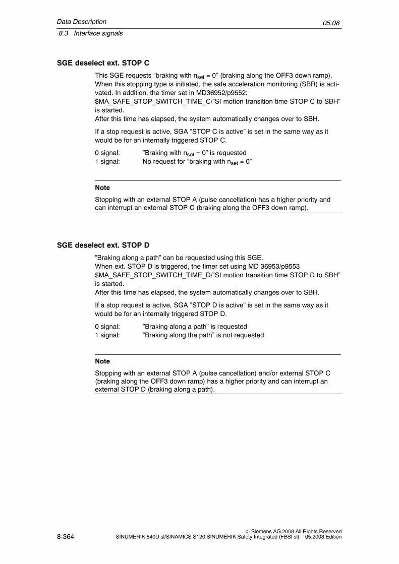
Data Description
8.3 Interface signals
05.08
8-364© Siemens AG 2008 All Rights Reserved
SINUMERIK 840D sl/SINAMICS S120 SINUMERIK Safety Integrated (FBSI sl) – 05.2008 Edition
SGE deselect ext. STOP C
This SGE requests ”braking with nset = 0” (braking along the OFF3 down ramp).When this stopping type is initiated, the safe acceleration monitoring (SBR) is acti-vated. In addition, the timer set in MD36952/p9552:$MA_SAFE_STOP_SWITCH_TIME_C/”SI motion transition time STOP C to SBH”is started.After this time has elapsed, the system automatically changes over to SBH.
If a stop request is active, SGA ”STOP C is active” is set in the same way as itwould be for an internally triggered STOP C.
0 signal: ”Braking with nset = 0” is requested1 signal: No request for ”braking with nset = 0”
Note
Stopping with an external STOP A (pulse cancellation) has a higher priority andcan interrupt an external STOP C (braking along the OFF3 down ramp).
SGE deselect ext. STOP D
”Braking along a path” can be requested using this SGE.When ext. STOP D is triggered, the timer set using MD 36953/p9553$MA_SAFE_STOP_SWITCH_TIME_D/”SI motion transition time STOP D to SBH”is started.After this time has elapsed, the system automatically changes over to SBH.
If a stop request is active, SGA ”STOP D is active” is set in the same way as itwould be for an internally triggered STOP D.
0 signal: ”Braking along a path” is requested1 signal: ”Braking along the path” is not requested
Note
Stopping with an external STOP A (pulse cancellation) and/or external STOP C(braking along the OFF3 down ramp) has a higher priority and can interrupt anexternal STOP D (braking along a path).
Data Description
8.3 Interface signals
05.08
8-365© Siemens AG 2008 All Rights ReservedSINUMERIK 840D sl/SINAMICS S120 SINUMERIK Safety Integrated (FBSI sl) – 05.2008 Edition
SGE deselect ext. STOP E
This SGE can be used to request a stop via the function ”extended stopping andretraction” (ESR). When an external STOP E is initiated the timer set using MD36954: $MA_SAFE_STOP_SWITCH_TIME_E/p9554: ”SI motion transition timeSTOP E to SBH” is started.After this time has elapsed, the system automatically changes over to SBH.
If a stop request is active, SGA ”STOP E is active” is set in the same way as itwould be for an internally triggered STOP E.0 signal: ”Stop/retraction” is requested1 signal: ”Stop/retraction” is not requested
Note
Stopping with an external STOP A (pulse cancellation) and/or external STOP C(braking along the OFF3 down ramp) and/or ext. STOP D (braking along a path)has/have a higher priority and can interrupt an external STOP E.
STOP E only produces a different response than STOP D if the user has config-ured the ESR function – extended stop and retract – and initiation of the ESR isprogrammed depending on $VA_STOPSI or $A_STOPESI. If no ESR is active, theSTOP E behaves like a STOP D. However, if the ESR was incorrectly configured,there is a delay up to the time $MC_ESR_DELAY_TIME1 and$MC_ESR_DELAY_TIME2 compared to STOP D until the braking operation isinitiated.
After these times have expired, braking is initiated at the current limit.
Close SGE brake (only the drive)
Using this SGE, a mechanical brake, that is controlled from the drive brake control,is closed. It is used to check brake closing while testing the mechanical brakesystem.
� If this SGE is set, the brake is closed.� If this SGE is deleted, then the brake assumes the status of the drive brake
control – i.e. it is not forcibly opened (no positive opening).
Note
This SGE must be connected to the brake control using a BiCo interconnection inthe drive (p0858 to source r9719, bit 13). This connection is parameterized asstandard.

Data Description
8.3 Interface signals
05.08
8-366© Siemens AG 2008 All Rights Reserved
SINUMERIK 840D sl/SINAMICS S120 SINUMERIK Safety Integrated (FBSI sl) – 05.2008 Edition
Description of signals from the monitoring channel
SGA SBH/SG active
This signal is used to signal the drive monitoring channel the status of the SBH andSG functions as follows:
0 signal: SBH/SG is not active1 signal: SBH/SG is active
SGA status, pulses are cancelled (drive only)
After the shutdown path test has been initiated using the SGE test stop selectionor if a limit value is violated with a resulting STOP A response, this signal is outputto indicate that the drive pulses have been internally cancelled (refer to Chapter6.1.1, ”Shutdown paths”).
0 signal: Pulses are enabled1 signal: Pulses are cancelled
SGA axis safely referenced
This indicates as to whether the relevant axis/spindle has been safely referenced(see Chapter 5.4.3, ”Axis states”).
0 signal: Axis is not safely referenced1 signal: Axis is safely referenced
SGA SN1+, SN1–, SN2+, SN2–, SN3+, SN3–, SN4+, SN4–
These signals are used to indicate which of the plus or minus cams of cam pair 1,2, 3 or 4 is ”actuated”.
0 signal:Axis/spindle is located to the left of the cam (actual value < cam position)1 signal:Axis/spindle is located to the right of the cam (actual value > cam position)
SGA safe cam track
These signals are used to display whether the axis is located on a cam that is as-signed to this cam track (this only applies to the ”safe cam track” function).
0 signal:The axis is not located on a cam of this cam track1 signal:The axis is located on a cam of this cam track

Data Description
8.3 Interface signals
05.08
8-367© Siemens AG 2008 All Rights ReservedSINUMERIK 840D sl/SINAMICS S120 SINUMERIK Safety Integrated (FBSI sl) – 05.2008 Edition
SGA safe cam range
The bits (4 bits per cam track) display in which cam range the axis is presently lo-cated (this is only valid for the ”safe cam track” function).
SGA safe cam range bits
This signal displays at which cam the axis is presently located (this is only valid forthe ”safe cam track” function).
0 signal: The axis is not located at this cam1 signal: The axis is located at this cam
SGA SBH active
The signal indicates the status of the safe operating stop (SBH).
1 signal: SBH is active0 signal: SBH is not active
SGA STOP A/B is active
This signal indicates that STOP A/B is active.The signal must be used for the forced checking procedure for external STOPs.
0 signal: STOP A/B is not active1 signal: STOP A/B is active
SGA STOP C is active
This signal indicates that STOP C is active.The signal must be used for the forced checking procedure for external STOPs.
0 signal: STOP C is not active1 signal: STOP C is active
SGA STOP D is active
This signal indicates that STOP D is active.The signal must be used for the forced checking procedure for external STOPs.
0 signal: STOP D is not active1 signal: STOP D is active

Data Description
8.3 Interface signals
05.08
8-368© Siemens AG 2008 All Rights Reserved
SINUMERIK 840D sl/SINAMICS S120 SINUMERIK Safety Integrated (FBSI sl) – 05.2008 Edition
SGA STOP E is active
This signal indicates that STOP E is active.The signal must be used for the forced checking procedure for external STOPs.
0 signal: STOP E is not active1 signal: STOP E is active
SGA ”n < nx
This SGA indicates whether the absolute value of the actual speed is above or be-low a speed specified in the machine data.
t
SGA ”n < nx”
n
0
1
nx
Fig. 8-2 Signal n < nx, dependent on the speed characteristic
!Warning
A STOP F (displayed using Alarms 27001, 27101 and onwards or F01711) onlyresults in a subsequent STOP B/A response, if at least one of the safety–relatedfunctions SBH, SG, SE or SN is active or selected. If only the function ”n < nx” isactive, then a STOP F does not result in a subsequent STOP B/A response.This means that if ”n < nx” is used as a safety function, at least one of the SBH,SG, SE or SN functions must either be active or selected (e.g. by selecting a highSG level).
Note
If the axis/spindle runs at a speed nx, then as a result of actual differences in thetwo monitoring channels, the SGA ”n < nx” can have different states.This must be taken into account in the safe processing of the SGA.

Data Description
8.3 Interface signals
05.08
8-369© Siemens AG 2008 All Rights ReservedSINUMERIK 840D sl/SINAMICS S120 SINUMERIK Safety Integrated (FBSI sl) – 05.2008 Edition
SG active, bits 1, 0
The SGA ”SG active bits 1, 0” displays which safely reduced speed and thereforewhich speed limit value is actively monitored. The SGAs are only updated if thefunction ”SBH/SG” is enabled and SG is active (SGE ”SBH/SG deselection” = 0and ”SBH deselection” = 1).
Table 8-8 Display of the active safely reduced speed
SGA
SG activeBit 1
SG activeBit 0
SBH/SG
active
SBHactive
Description
=0 =0 1 1 SBH is active (safely reduced speed is not active)
=0 =0 1 0 Speed limit value for SG1 active
=0 =1 1 0 Speed limit value for SG2 active
=1 =0 1 0 Speed limit value for SG3 active
=1 =1 1 0 Speed limit value for SG4 active
=0 =0 0 0 Neither SBH nor SG is active
Note:The state ”SG active bits 1, 0” = ”0” has different meanings. A clear interpretation can be obtained by additionally evalu-ating the SGAs ”SBH active” and ”SBH/SG active”.
Communication failure
For a sign–of–life error or CRC error, this signal is set to TRUE. The PLC–SPLremains functional in so much that the drive monitoring channel is not required.SGE to the drive are effective. The SGA from the drive are frozen at the state be-fore communications failed.Response time when the sign of life character from the drive fails: 3 sResponse time for CRC errors from the drive: 3 PLC cycles
Fault, data transfer
For a CRC error, this signal is set to TRUE. The PLC–SPL remains functional in somuch that the drive monitoring channel is not required. SGE to the drive are effec-tive. The SGA from the drive are frozen at the state before communications failed.Response time for CRC errors from the drive: 3 PLC cycles
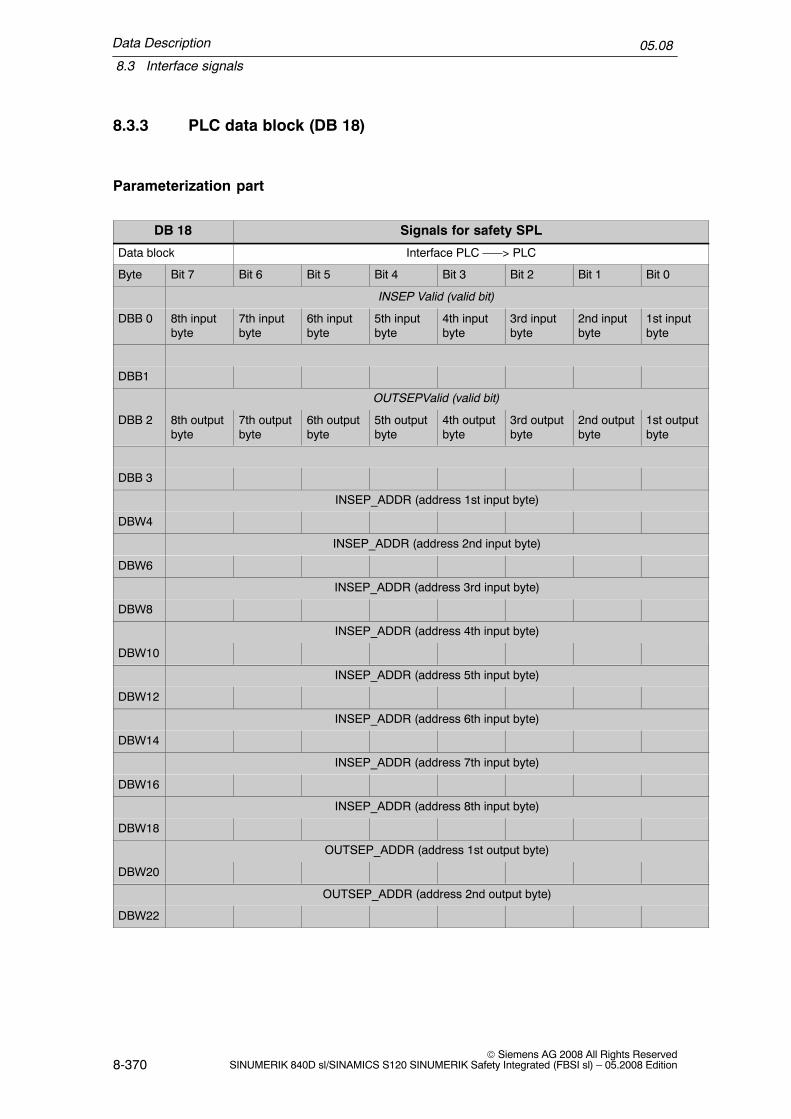
Data Description
8.3 Interface signals
05.08
8-370© Siemens AG 2008 All Rights Reserved
SINUMERIK 840D sl/SINAMICS S120 SINUMERIK Safety Integrated (FBSI sl) – 05.2008 Edition
8.3.3 PLC data block (DB 18)
Parameterization part
DB 18 Signals for safety SPL
Data block Interface PLC –––> PLC
Byte Bit 7 Bit 6 Bit 5 Bit 4 Bit 3 Bit 2 Bit 1 Bit 0
INSEP Valid (valid bit)
DBB 0 8th inputbyte
7th inputbyte
6th inputbyte
5th inputbyte
4th inputbyte
3rd inputbyte
2nd inputbyte
1st inputbyte
DBB1
OUTSEPValid (valid bit)
DBB 2 8th outputbyte
7th outputbyte
6th outputbyte
5th outputbyte
4th outputbyte
3rd outputbyte
2nd outputbyte
1st outputbyte
DBB 3
INSEP_ADDR (address 1st input byte)
DBW4
INSEP_ADDR (address 2nd input byte)
DBW6
INSEP_ADDR (address 3rd input byte)
DBW8
INSEP_ADDR (address 4th input byte)
DBW10
INSEP_ADDR (address 5th input byte)
DBW12
INSEP_ADDR (address 6th input byte)
DBW14
INSEP_ADDR (address 7th input byte)
DBW16
INSEP_ADDR (address 8th input byte)
DBW18
OUTSEP_ADDR (address 1st output byte)
DBW20
OUTSEP_ADDR (address 2nd output byte)
DBW22

Data Description
8.3 Interface signals
05.08
8-371© Siemens AG 2008 All Rights ReservedSINUMERIK 840D sl/SINAMICS S120 SINUMERIK Safety Integrated (FBSI sl) – 05.2008 Edition
Signals for safety SPLDB 18
OUTSEP_ADDR (address 3rd output byte)
DBW24
OUTSEP_ADDR (address 4th output byte)
DBW26
OUTSEP_ADDR (address 5th output byte)
DBW28
OUTSEP_ADDR (address 6th output byte)
DBW30
OUTSEP_ADDR (address 7th output byte)
DBW32
OUTSEP_ADDR (address 8th output byte)
DBW34
DBB36 STOP_MODE
SPL_READY
DBB37
Note
DBB 0–35 is not relevant for SINUMERIK 840D sl.
Data area/errors
DB 18 Signals for safety SPL
Data block Interface PLC –––> NCK
Byte Bit 7 Bit 6 Bit 5 Bit 4 Bit 3 Bit 2 Bit 1 Bit 0
Data area of SPL inputs/outputs
SPL_DATA.INSEP[1 ...32]
DBD 38
SPL_DATA.INSEP[33 ...64]
DBD 42
SPL_DATA.OUTSEP[1 ...32]
DBD 46
SPL_DATA.OUTSEP[33 ...64]
DBD 50
Data area for user SPL
SPL_DATA.INSIP[1 ...32]

Data Description
8.3 Interface signals
05.08
8-372© Siemens AG 2008 All Rights Reserved
SINUMERIK 840D sl/SINAMICS S120 SINUMERIK Safety Integrated (FBSI sl) – 05.2008 Edition
Signals for safety SPLDB 18
DBD 54
SPL_DATA.INSIP[33 ...64]
DBD 58
SPL_DATA.OUTSIP[1 ...32]
DBD 62
SPL_DATA.OUTSIP[33 ...64]
DBD 66
SPL_DATA.MARKERSIP[1 ...32]
DBD 70
SPL_DATA.MARKERSIP[33 ...64]
DBD 74
Difference in signal level NCK – PLC for diagnostics
SPL_DELTA.INSEP[1 ...32]
DBD 78
SPL_DELTA.INSEP[33 ...64]
DBD 82
SPL_DELTA.OUTSEP[1 ...32]
DBD 86
SPL_DELTA.OUTSEP[33 ...64]
DBD 90
SPL_DELTA.INSIP[1 ...32]
DBD 94
SPL_DELTA.INSIP[33 ...64]
DBD 98
SPL_DELTA.OUTSIP[1 ...32]
DBD 102
SPL_DELTA.OUTSIP[33 ...64]
DBD 106
SPL_DELTA.MARKERSIP[1 ...32]
DBD 110
SPL_DELTA.MARKERSIP[33 ...64]
DBD 114
DBB 118 CMDSI
DBB 119 COMM_TO

Data Description
8.3 Interface signals
05.08
8-373© Siemens AG 2008 All Rights ReservedSINUMERIK 840D sl/SINAMICS S120 SINUMERIK Safety Integrated (FBSI sl) – 05.2008 Edition
Signals for safety SPLDB 18
DBD 120Error code0 = no error
1 – 320 = signal number starting from SPL_DATA.INSEP[1]
DBD 124 Crosswise data comparison stack level display(diagnostics capability: How many SPL signals currently have different levels)
Additional data areas
DB 18 Signals for safety SPL
Data block Interface PLC –––> NCK
Byte Bit 7 Bit 6 Bit 5 Bit 4 Bit 3 Bit 2 Bit 1 Bit 0
Data area of single–channel inputs/outputs
PLCSIOUT[1 ...8]
DBB128
PLCSIOUT[9 ...16]
DBB129
PLCSIOUT[17 ..24]
DBB130
PLCSIOUT[25 ...32]
DBB131
PLCSIIN[1 ...8]
DBB132
PLCSIIN[9 ...16]
DBB133
PLCSIIN[17 ...24]
DBB134
PLCSIIN[25 ...32]
DBB135
SPL status[1 ...16]
DBW136
INSEP_PROFISAFE[1 ...8] PROFIsafe module(s) for
DBB138 8th inputbyte
7th inputbyte
6th inputbyte
5th inputbyte
4th inputbyte
3rd inputbyte
2nd inputbyte
1st inputbyte
DBB139
OUTSEP_PROFISAFE[1 ...8] PROFIsafe module(s) for
DBB140 8th outputbyte
7th outputbyte
6th outputbyte
5th outputbyte
4th outputbyte
3rd outputbyte
2nd outputbyte
1st outputbyte

Data Description
8.3 Interface signals
05.08
8-374© Siemens AG 2008 All Rights Reserved
SINUMERIK 840D sl/SINAMICS S120 SINUMERIK Safety Integrated (FBSI sl) – 05.2008 Edition
Signals for safety SPLDB 18
DBB141
DBB142
to
DBB149

Data Description
8.3 Interface signals
05.08
8-375© Siemens AG 2008 All Rights ReservedSINUMERIK 840D sl/SINAMICS S120 SINUMERIK Safety Integrated (FBSI sl) – 05.2008 Edition
Signals for safety SPLDB 18
DBB150
to
DBB157
DBB158
to
DBB188
SPL status signals for DB18.DBW136
DB18.DBX136.0 SPL_STATUS[1] NCK–SPL interfaces parameterized
DB18.DBX136.1 SPL_STATUS[2] NCK–SPL program file exists
DB18.DBX136.2 SPL_STATUS[3] NCK waits for the PLC to boot
DB18.DBX136.3 SPL_STATUS[4] NCK and PLC in cyclic operation
DB18.DBX136.4 SPL_STATUS[5] Call FB4 processing for SPL
DB18.DBX136.5 SPL_STATUS[6] End FB4 processing for SPL
DB18.DBX136.6 SPL_STATUS[7] Call FC9 processing for SPL
DB18.DBX136.7 SPL_STATUS[8] End FC9 processing for SPL
DB18.DBX137.0 SPL_STATUS[9] SPL start implemented using PROG_EVENTmechanism
DB18.DBX137.1 SPL_STATUS[10] Crosswise data comparison started, NCK
DB18.DBX137.2 SPL_STATUS[11] Crosswise data comparison started, PLC
DB18.DBX137.3 SPL_STATUS[12] NCK–SPL checksum checking active
DB18.DBX137.4 SPL_STATUS[13] All SPL protective mechanisms active
DB18.DBX137.5 SPL_STATUS[14] End of SPL program reached
DB18.DBX137.6 SPL_STATUS[15] Not assigned
DB18.DBX137.7 SPL_STATUS[16] Not assigned
Table 8-9 Overview of DB 18 signals
DB18
Signal r – read w – write
Type Value range Comment
Parameterization part
INSEP_VALID[1..8](no significance)
r/w Bool 0 = INSEP[1..8] No automatic transfer,can be supplied from the user pro-gram (AWP)1 = Transfer of input byte, specified inINSEP_ADDR[1..8] to INSEP[1..8] bythe basic program

Data Description
8.3 Interface signals
05.08
8-376© Siemens AG 2008 All Rights Reserved
SINUMERIK 840D sl/SINAMICS S120 SINUMERIK Safety Integrated (FBSI sl) – 05.2008 Edition
Table 8-9 Overview of DB 18 signals
Signal CommentValue rangeTyper – read w – write
OUT-SEP_VALID[1..8](no significance)
r/w Bool 0 = OUTSEP[1..8] No automatic trans-fer, can be retrieved from the user pro-gram (AWP)1 = Transfer to the output byte, speci-fied in OUTSEP[1..8] from OUT-SEP_ADDR[1..8] by the basic pro-gram
INSEP_ADDR[1..8](no significance)
r/w Int 1..EB max Address, input byte
OUT-SEP_ADDR[1..8](no significance)
r/w Int 1..AB max Address, output byte
SPL_READY r/w Bool 0 = commissioning phase(for a crosswise data comparison er-ror, a STOP D is not initiated)1 = commissioning completed(for a crosswise data comparison er-ror, STOP D is initiated)
STOP_MODE r/w Bool If DB18, DBX36.1 was set to 1, for acrosswise data comparison error,instead of an external STOP D, an ex-ternal STOP E is transferred to thedrive
Data area/status
SPL_DATA Net (useful) data:
INSEP[1..64] r Bool External PLC input for the SPL
OUTSEP[1..64] r/w Bool External PLC output for the SPL
INSIP[1..64] r Bool Internal PLC input for the SPL
OUTSIP[1..64] r/w Bool Internal PLC output for the SPL
MARKERSIP[1..64] r/w Bool Marker for SPL
SPL_DELTA Signal differences for diagnostics:
INSEP[1..64] r Bool External PLC input for the SPL
OUTSEP[1..64] r Bool External PLC output for the SPL
INSIP[1..64] r Bool Internal PLC input for the SPL
OUTSIP[1..64] r Bool Internal PLC output for the SPL
MARKERSIP[1..64] r Bool Marker for SPL
CMDSI r/w Bool The timeout value in the crosswisedata comparison is extended by a fac-tor of 10
COMM_TO r Bool 0 –> 1 communications timeout de-tected, PLC will go to STOP in 5 s

Data Description
8.3 Interface signals
05.08
8-377© Siemens AG 2008 All Rights ReservedSINUMERIK 840D sl/SINAMICS S120 SINUMERIK Safety Integrated (FBSI sl) – 05.2008 Edition
Table 8-9 Overview of DB 18 signals
Signal CommentValue rangeTyper – read w – write
STATSI r Dint 1 – 320 Status: 0 – no error1 – 320 error No. corresponds to sig-nal from SPL_DATA whose signallevel difference resulted in a crosswisedata comparison error
LEVELSI r Dint Crosswise data comparison stacklevel display(diagnostics capability: How manySPL signals currently have differentlevels)
PLCSIIN[1 ..32] r/w Bool Single–channel signals from the PLCto NCK
PLCSIOUT[1 ..32] r Bool Single–channel signals from the NCKto the PLC
SPL_STATUS r Bool Status signals from NCK to PLC
INSEP_PROFI-SAFE
r Bool 0 = no assignment from PROFIsafe Fmodules to INSEP [1..8]1 = transfer from PROFIsafe F moduleto INSEP [1..8] using the basic pro-gram
OUTSEP_PROFI-SAFE
r Bool 0 = no assignment from PROFIsafe Fmodules to OUTSEP [1..8]1 = transfer from OUTSEP [1..8] toPROFIsafe F module using the basicprogram

Data Description
8.4 System variables
05.08
8-378© Siemens AG 2008 All Rights Reserved
SINUMERIK 840D sl/SINAMICS S120 SINUMERIK Safety Integrated (FBSI sl) – 05.2008 Edition
8.4 System variables
8.4.1 System variable for SINUMERIK 840D sl
System variables
Table 8-10 Overview of system variables
System variables Description Value range Datatype
Possible access for
Part program Synchronizedaction
r w r w
Actual position
$VA_IS[axis] Safe actual position for Safety In-tegrated
Axis identifierGEOAXCHANAXMACHAXSPINDLE
DOUBLE x x
$AA_IM[axis] Actual position of the closed–loopcontrol
Axis identifierGEOAXCHANAXMACHAXSPINDLE
DOUBLE x x
$VA_IM[axis] Encoder actual value in the ma-chine coordinate system
Axis identifierGEOAXCHANAXMACHAXSPINDLE
DOUBLE x x
Internal inputs/outputs
$A_INSI[n] NCK input n = 1, 2, ... 64stand for theNo. of the input
BOOL x x
$A_INSID[n] NCK inputs n = 1, 2 INT x x
$A_INSIP[n] Image, PLC input n = 1,2, ...64 BOOL x x
$A_INSIPD[n] Image of the PLC – SPL inputsfrom the drive monitoring channel
n = 1, 2 INT x x
$A_OUTSI[n] NCK output n = 1, 2, ... 64stand for theNo. of the out-put
BOOL x x x x
$A_OUTSID[n] NCK outputs n = 1, 2 INT x x x x
$A_OUTSIP[n] Image, PLC output n = 1, 2, ... 64 BOOL x x
$A_OUTSIPD[n] Image of the PLC – SPL outputsfrom the drive monitoring channel
n = 1, 2 INT x x
External inputs/outputs
$A_INSE[n] NCK input n = 1, 2, ... 64stands for theNo. of the input1)
BOOL x x
$A_INSED[n] NCK inputs n = 1, 2 1) INT x x

Data Description
8.4 System variables
05.08
8-379© Siemens AG 2008 All Rights ReservedSINUMERIK 840D sl/SINAMICS S120 SINUMERIK Safety Integrated (FBSI sl) – 05.2008 Edition
Table 8-10 Overview of system variables
wrwr
$A_INSEP[n] Image of a PLC–SPL input fromthe PLC HW I/O
n = 1, 2, ... 64stand for theNo. of the input
BOOL x x
$A_INSEPD[n] Image of the PLC – SPL inputsfrom PLC HW I/O
n = 1, 2 INT x x
$A_OUTSE[n] NCK output n = 1, 2, ... 64stands for theNo. of the out-put 1)
BOOL x x x x
$A_OUTSED[n] NCK outputs n = 1, 2 1) INT x x x x
$A_OUTSEP[n] Image of a PLC – SPL outputfrom the PLC HW I/O
n = 1, 2, ... 64stand for theNo. of the out-put
BOOL x x
$A_OUTSEPD[n] Image of PLC – SPL outputs fromPLC HW I/O
n = 1, 2 INT x x
Markers and timers
$A_MARKERSI[n] Markers n = 1, 2, ... 64stands for theNo. of themarker
BOOL x x x x
$A_MARKERSID[n] Markers n = 1, 2 INT x x x x
$A_MARKERSIP[n] Image of the PLC markers n = 1,2, ...64 BOOL x x
$A_MARKER-SIPD[n]
Image of the PLC markers n = 1, 2 INT x x
$A_TIMERSI[n] Timer n = 1, 2...16stand for theNo. of the timer
REAL x x x x
$A_FRDP_DIAG[n] The cause of the communicationerror determined fromF_RECVDP is communicated
n = 1, 2, 3 INT x x
$A_FRDP_SEND-MODE[n]
Actual operating mode of the F–CPU of the F_SENDDP commu-nication partner
n = 1, 2, 3 BOOL x x
Miscellaneous$A_STATSID Crosswise data comparison error
triggered if the value is not equalto 0
Bits 0...27crosswise datacomparison er-ror in the I/Osignals or flagbitsBit 28 cross-wise data com-parison error”SPL protec-tion status”Bit 29 timeoutin the commu-nications be-tween NCKand SPLBit 30 PLC sig-nals a stop tothe NCK
INT x x

Data Description
8.4 System variables
05.08
8-380© Siemens AG 2008 All Rights Reserved
SINUMERIK 840D sl/SINAMICS S120 SINUMERIK Safety Integrated (FBSI sl) – 05.2008 Edition
Table 8-10 Overview of system variables
wrwr
$A_CMDSI 10x change timer timeout valuefor long forced checking proce-dure pulses and/or single–channeltest stop logic
Bit 0 = 110x time active
BOOL x x x x
$A_LEVELSID Crosswise data comparison stacklevel display: Number of signalsfor which NCK and PLC detectdifferent signal levels
0...320 INT x x
$A_XFAULTSI Bit 0=1:In a crosswise data comparisonbetween NCK and drive of anyparticular safety axis, an actualvalue error was detected.Bit 1=1:In the crosswise data comparisonbetween NCK and drive of anyaxis, an error was detected andthe delay time until STOP B is ini-tiated for this axis is either runningor has already expired.
[0,3] INT x x
$VA_XFAULTSI[axis]
Bit 0=1:The crosswise data comparisonfor this axis between NCK anddrive has detected an actual valueerrorBit 1=1:In the crosswise data comparisonbetween NCK and the drive of thisaxis, an error was detected andthe delay time until STOP B is ini-tiated in this axis is either runningor has already expired.
[0,3] INT x x
$VA_STOPSI[axis] Current Safety Integrated stop ofthe relevant axis–1: No stop0: Stop A1: Stop B2: Stop C3: Stop D4: Stop E5: Stop F10: Test stop11: Test, external pulse
cancellation
[–1,11] INT x x
$A_STOPESI Current Safety Integrated STOP Efor any axis0: No stopotherwise: For one of the axes,
a Stop E is present
[0,MAX_INT] INT x x
$A_PLCSIIN[1...32] Single–channel direct commu-nication between NCK and PLC–SPL. Signals can be written bythe PLC and read by the NCK.
[FALSE,TRUE]
BOOL x x
$A_PLCSI-OUT[1...32]
Single–channel direct commu-nication between NCK and PLC–SPL. Signals can be read by thePLC, written and read by theNCK.
[FALSE,TRUE]
BOOL x x

Data Description
8.4 System variables
05.08
8-381© Siemens AG 2008 All Rights ReservedSINUMERIK 840D sl/SINAMICS S120 SINUMERIK Safety Integrated (FBSI sl) – 05.2008 Edition
Table 8-10 Overview of system variables
wrwr
$AC_SAFE_SYNA_MEM
Free safety synchronized actionelements
[0,MAX_INT] x x
Note:
r –> read, w –> writeAn implicit preliminary stop is generatedOnly permitted in the commissioning phase1) The number of these system variables depends on the option SI Basic or SI Comfort. For SI Basic, the following
applies:4 INSE[1..4]4 OUTSE[1..4]4 INSED[1]4 OUTSED[1]
8.4.2 Description of the system variables
System variable $VA_IS
The safe actual value, used by SI, can be read and further processed by the NCpart program for every axis/spindle.
Example:When an NC part program is started, Safety Integrated checks whether axis Xwould move into the vicinity of shutdown limits as a result of the zero offsets whena program is processed. The part program can be programmed as follows, forexample:
IF ($VA_IS[X] < 10000) GOTOF POS_OK ; if the actual value is too high,MESG (”Axis has nearly reached limit switch!”) ; then the following message,POS_OK: ; otherwise, continue here...
The variable can also be used in synchronous actions in order to reduce the over-ride when the axis is nearly at the limit switch.
Difference between $VA_IS and $AA_IM
Both variable $VA_IS and variable $AA_IM can be used to read actual values.

Data Description
8.4 System variables
05.08
8-382© Siemens AG 2008 All Rights Reserved
SINUMERIK 840D sl/SINAMICS S120 SINUMERIK Safety Integrated (FBSI sl) – 05.2008 Edition
Table 8-11 Difference between $VA_IS and $AA_IM
Variable Description
$VA_IS Reading the actual value used by SI
$AA_IM Reading the actual value used by the closed–loop control (setpoint for theclosed–loop position control)
References: /PGA/, Programming Manual Job Planning
System variables $A_XFAULTSI and $VA_XFAULTSI
For crosswise data comparison errors between the NCK and SINAMICS S120, theresponse depends on the actual operating state:
� SBH, SG, SE or SN active: A crosswise data comparison error causes a transi-tion from Stop F to Stop B – which in turn initiates the fastest possible brakingof the axis. A Stop A is then initiated and the pulse enable is cancelled.
� SBH and SG are not active and SE/SN is not used or Stop C/D/E has alreadybeen activated: In this case, a Stop F due to a crosswise data comparison errordoes not result in any further action – only Alarm 27001 is output that providesinformation. Processing then continues.
This chain of responses is not altered to ensure the appropriate level of safety forpersonnel.
To allow responses to a crosswise data comparison error, system variable$A_XFAULTSI is used to display that a crosswise data comparison error has oc-curred on a particular SI axis. Retraction can then be initiated as a response to thissystem variable.
Further, an axis–specific system variable $VA_XFAULTSI[<axis name>] has beenintroduced so that, if necessary, axis–specific responses can be applied.
The system variables are updated independent of whether SI monitoring functionsare active or inactive.
$A_XFAULTSI
Information about Stop F for a safety axis:
Bit 0 = 1: In a crosswise data comparison between NCK and drive of any par-ticular safety axis, an actual value error was detected.
Bit 1 = 1: In the crosswise data comparison between NCK and drive of anyaxis, an error was detected and the delay time until Stop B is initi-ated for this axis is either running or has already expired.($MA_SAFE_STOP_SWITCH_TIME_F)

Data Description
8.4 System variables
05.08
8-383© Siemens AG 2008 All Rights ReservedSINUMERIK 840D sl/SINAMICS S120 SINUMERIK Safety Integrated (FBSI sl) – 05.2008 Edition
$VA_XFAULTSI[X] (X = axis identifier)
Information about Safety Integrated Stop F for this axis
Bit 0 set In the crosswise data comparison between NCK and drive anactual value error was detected.
Bit 1 set In the crosswise data comparison between NCK and drive – anerror was detected and the delay time – up until a STOP B($MA_SAFE_STOP_SWITCH_TIME_F) is initiated – is eitherrunning or has expired.
System variable $VA_STOPSI
Axial system variable that contains the present stop. For a value of 2, a Stop E isactive for this axis.
System variable $A_STOPESI
Global system variable that with a value not equal to 0 indicates that a Stop E isactive for one particular axis.
System variables $A_INSI[1...64]
The status signals of the NCK monitoring channel can be used in the NCK–SPLusing these system variables. Each of the system variables $A_INSI[1...64] can beassigned any safety–related output signal or the AND logic operation of severalsignals using axial MD $MA_SAFE_xxx_OUTPUT. These system variables canonly be read by the user program.
Parameterizing example:– $MA_SAFE_CAM_PLUS_OUTPUT[0] = 04010101H=> the SGA ”SN1+” can be evaluated in the SPL using the system variable$A_INSI[1].
Programming example:; Copying an SGA from the internal SPL interface into the external
SPL interface
N1010 IDS = 01 DO $A_OUTSE[1] = $A_INSI[1]
These system variables can only be read by the user program.
System variable $A_INSE[1...64]
The system variables $A_INSE contain the input circuit of the NCK–SPL.

Data Description
8.4 System variables
05.08
8-384© Siemens AG 2008 All Rights Reserved
SINUMERIK 840D sl/SINAMICS S120 SINUMERIK Safety Integrated (FBSI sl) – 05.2008 Edition
System variables $A_INSED[1,2]
Image of the safety input signals (external NCK interface).
System variables $A_INSID[1,2]
The status signals of the NCK monitoring channel can be evaluated in the NCK–SPL in a double–word–serial fashion using this system variable:
$A_INSID[1] corresponds to $A_INSI[1...32]$A_INSID[2] corresponds to $A_INSI[33...64]
These system variables can only be read by the user program.
System variables $A_OUTSE[1...64]
The system variables $A_OUTSE contain the outputs of the NCK–SPL.
System variables $A_OUTSI[1...64]
The control signals of the NCK monitoring channel can be addressed from theNCK–SPL using these system variables. Each of the system variables$A_OUTSI[1...64] can be simultaneously assigned any one or several safety–re-lated input signals by using the axial MD $MA_SAFE_xxx_INPUT.
Parameterizing example:– $MA_SAFE_VELO_SELECT_INPUT[0] = 04010204H => The SGE ”SG selection, bit 0” is controlled in the SPL using the system vari-able $A_OUTSI[36].
Programming example:; SGA ”cam 1+” (refer above) controls the SG selection
; N1020 IDS = 02 DO $A_OUTSI[36] = $A_INSI[1]
These system variables can be read by the user program and written into bySAFE.SPF.
System variables $A_OUTSID[1,2]
The control signals of the NCK monitoring channel can be addressed in the NCK–SPL in a double–word–serial fashion using these system variables:
$A_OUTSID[1] corresponds to $A_OUTSI[1...32]$A_OUTSID[2] corresponds to $A_OUTSI[33...64]
These system variables can be read by the user program and written into bySAFE.SPF.

Data Description
8.4 System variables
05.08
8-385© Siemens AG 2008 All Rights ReservedSINUMERIK 840D sl/SINAMICS S120 SINUMERIK Safety Integrated (FBSI sl) – 05.2008 Edition
System variables $A_OUTSED[1,2]
The external status signals can be addressed by the NCK–SPL in a double–word–serial fashion using these system variables:
$A_OUTSED[1] corresponds to $A_OUTSE[1...32]$A_OUTSED[2] corresponds to $A_OUTSE[33...64]
These system variables can be read by the user program and written into bySAFE.SPF.
System variables $A_MARKERSI[1...64]
Up to 64 status bits of the SPL can be flagged using these system variables. Themarkers are read and written directly into the NCK–SPL.
Programming example:N1030 IDS = 03 DO $A_MARKERSI[2] = $A_OUTSI[1] AND $A_INSE[2]
N1040 IDS = 04 DO $A_OUTSE[1] = $A_MARKERSI[2]
System variables $A_MARKERSID[1,2]
The SPL status bits can be addressed in a word–serial fashion using these systemvariables.
$A_MARKERSID[1] corresponds to $A_MARKERSI[1...32]$A_MARKERSID[2] corresponds to $A_MARKERSI[33...64]
System variables $A_TIMERSI[1...16]
Up to sixteen timers can be programmed using these system variables.
Programming example:; Set marker once after two seconds, reset the timer value and stop
the timer.
N1050 IDS = 05 WHENEVER $A_TIMERSI[1] > 2.0 DO
$A_TIMERSI[1] = 0.0 $A_TIMERSI[1] = –1.0
$A_MARKERSI[2] = 1
System variable $A_STATSID
This system variable can be using in the NCK–SPL to evaluate whether, in thecrosswise data comparison between NCK and PLC, an error was detected in thetwo–channel control/processing of the control and status signals. This gives theuser the opportunity to respond to this error with specific synchronous actions.

Data Description
8.4 System variables
05.08
8-386© Siemens AG 2008 All Rights Reserved
SINUMERIK 840D sl/SINAMICS S120 SINUMERIK Safety Integrated (FBSI sl) – 05.2008 Edition
Bit 0... 27: Crosswise data comparison error in the input/output signals ormarkers.
Bit 28: Crosswise data comparison error ”SPL protection status” (status$MN_PREVENT_SYNACT_LOCK not equal to DB18.DBX36.0).
Bit 29: Time error in the communications between NCK and PLC (in 5 s, allext. NCK–SPL outputs are set to zero, the PLC goes to stop).
Bit 30: PLC signals a stop to the NCK.
Programming example:; For a crosswise data comparison error, set ext. output N1060 IDS = 06 WHENEVER $A_STATSID <> 0 DO $A_OUTSE[1] = 1
These system variables can only be read by the user program.
System variable $A_CMDSI[1]
This system variable can be used to increase the time up to 10 s monitoring thesignal changes in the crosswise data comparison between NCK and PLC.
This means that signal differences between the NCK and PLC system variablescan be tolerated for up to 10s without Alarm 27090 being output.
This system variable can be read and written into by the user program.
System variable $A_LEVELSID
This system variable is used to display the stack level of the signal change moni-toring in the crosswise data comparison between NCK and PLC. This variable indi-cates the current number of signals to be checked by the crosswise data compari-son function.
System variables $A_xxxP(D)
Images (mapping) of the PLC–SPL interface and markers are provided to make iteasier to commission the SPL. The system variables are updated in the sameclock cycle as the crosswise data comparison between the NCK and the PLC.These system variables can only be accessed reading.These system variables may only be used in the commissioning phase.As soon as commissioning has been signaled as completed, access to thesesystem variables is blocked. If these program commands are processed, Alarm17210 is output to indicate an error condition.

Data Description
8.4 System variables
05.08
8-387© Siemens AG 2008 All Rights ReservedSINUMERIK 840D sl/SINAMICS S120 SINUMERIK Safety Integrated (FBSI sl) – 05.2008 Edition
System variables $A_INSIP[1...64]
Images of the PLC–side internal SPL input signals (status signals from the drivemonitoring channel) can be read using these system variables.
Associated DB18 values: DB18.DBX54.0 ... DBX61.7
System variables $A_INSIPD[1,2]
Images of the PLC–side internal SPL input signals (status signals from the drivemonitoring channel) can be read in a double–word–serial fashion (32 bit) usingthese system variables.
Associated DB18 values: DB18.DBD54, DBD58
System variables $A_OUTSIP[1...64]
Images of the PLC–side internal SPL output signals (control signals to the drivemonitoring channel) can be read using these system variables.
Associated DB18 values: DB18.DBX62.0 ... DBX69.7
System variables $A_OUTSIPD[1,2]
Images of the PLC–side internal SPL output signals (control signals to the drivemonitoring channel) can be read in a double–word–serial fashion (32 bit) usingthese system variables.
Associated DB18 values: DB18.DBD62, DBD66
System variables $A_INSEP[1...64]
Images of the PLC–side external SPL input signals (control signals to the PLC–SPL) can be read using these system variables.
Associated DB18 values: DB18.DBX38.0 ... DBX45.7
System variables $A_INSEPD[1,2]
Images of the PLC–side external SPL input signals (control signals to the PLC–SPL) can be read in a double–word–serial fashion (32 bit) using these system vari-ables.
Associated DB18 values: DB18.DBD38, DBD42
System variables $A_OUTSEP[1...64]
Images of the PLC–side external SPL output signals (status signals from the PLC–SPL) can be read using these system variables.
Associated DB18 values: DB18.DBX46.0 ... DBX53.7

Data Description
8.4 System variables
05.08
8-388© Siemens AG 2008 All Rights Reserved
SINUMERIK 840D sl/SINAMICS S120 SINUMERIK Safety Integrated (FBSI sl) – 05.2008 Edition
System variables $A_OUTSEPD[1,2]
Images of the PLC–side external SPL output signals (status signals from the PLC–SPL) can be read in a double–word–serial fashion (32 bit) using these system vari-ables.
Associated DB18 values: DB18.DBD46, DBD50
System variables $A_MARKERSIP[1..64]
Images of the PLC–side SPL markers can be read using these system variables.
Associated DB18 values: DB18.DBX70.0 ... DBX77.7
System variables $A_MARKERSIPD[1,2]
Images of the PLC–side SPL markers can be read in a double–word–serial fashion(32 bit) using these system variables.
Associated DB18 values: DB18.DBD70, DBD74
System variable $A_PLCSIIN[1..32]
Single–channel direct communication between NCK and PLC–SPL. Signals can bewritten by the PLC and read by the NCK.
System variable $A_PLCSIOUT[1..32]
Single–channel direct communication between NCK and PLC–SPL. Signals can beread by the PLC and read and written by the NCK.
System variable $AC_SAFE_SYNA_MEM
Variable $AC_SAFE_SYNA_MEM contains the number of free synchronizing ac-tion elements Safety Integrated. The number before and after SAFE.SPF has runis read in order to determine the value of the required elements. The differencebetween the two values is then the number that (with a safety margin) must be en-tered into machine data $MC_MM_NUM_SAFE_SYNC_ELEMENTS.
Note
Write access operations to all named system variables are only possible from theprogram saved in program file /_N_CST_DIR/_N_SAFE_SPF reserved for theSPL. Access operations from other programs are flagged as an error with Alarm17070.
9-389© Siemens AG 2008 All Rights ReservedSINUMERIK 840D sl/SINAMICS S120 SINUMERIK Safety Integrated (FBSI sl) – 05.2008 Edition
Commissioning
Note
Not all of the HMI functions shown are available in all of the HMI versions (HMIEmbedded, HMI sl, HMI Advanced).
!Warning
After hardware and/or software components have been changed or replaced, it isonly permissible to boot the system and activate the drives when the protectivedevices are closed. Personnel shall not be present within the danger zone.
Depending on the change or replacement, it may be necessary to carry out a new,partial or complete acceptance test (refer to Chapter 9.5 Acceptance report).Before persons may re–enter the hazardous area, the drives should be tested toensure that they exhibit stable behavior by briefly moving them in both the plusand minus directions (+/–).It is especially important to carefully observe this for high–speed linear or torquemotors.
Note
The function ”safe software limit switches” (SE) is also called ”safe limit positions”and the function ”safe software cams” (SN) is also called ”safe cams”.
!Warning
If SI functions SH, SBH or SG have been enabled, then they become operationalafter the control system has booted (basic display on screen). For the SE and SNfunctions safety–related position evaluation is only possible after safety–relatedreferencing has been successfully completed.
9

Commissioning 05.08
9-390© Siemens AG 2008 All Rights Reserved
SINUMERIK 840D sl/SINAMICS S120 SINUMERIK Safety Integrated (FBSI sl) – 05.2008 Edition
!Warning
Protection of operating personnel must be the primary consideration whenconfiguring machine data for SINUMERIK Safety Integrated. This is this reasonthat the parameterizable tolerances, limit values and delay times should bedetermined and optimized during the commissioning phase dependent on themachine design and arrangement.

Commissioning
9.1 HMI screens and softkeys
05.08
9-391© Siemens AG 2008 All Rights ReservedSINUMERIK 840D sl/SINAMICS S120 SINUMERIK Safety Integrated (FBSI sl) – 05.2008 Edition
9.1 HMI screens and softkeys
Configuring safety–related functions
When selecting ”Commissioning/NC/Safety–Integrated” you reach the startingscreen for the Safety Integrated commissioning support. The following screen isdisplayed 9-1:
Fig. 9-1 Example for ”Commissioning/NC/Safety–Integrated” for 840D sl
View of the axes (horizontal softkey)
Softkey ”safe axes”
All of the axes are listed in this screen that were activated for Safety Integrated.
Softkey ”All axes”
Here, defined axes are listed independent of whether it involves a safety axis ornot.
Softkey ”Copy SI data”
When the softkey is pressed, all NC machine data, relevant for the SI functions, istransferred into the corresponding drive parameters.

Commissioning
9.1 HMI screens and softkeys
05.08
9-392© Siemens AG 2008 All Rights Reserved
SINUMERIK 840D sl/SINAMICS S120 SINUMERIK Safety Integrated (FBSI sl) – 05.2008 Edition
The SI machine data/parameters to define the encoder mounting arrangementmust be separately entered for the NCK and drive by the commissioning engineer.The copy function has no effect for the drive parameters marked in the Table 8-2”Parameters for SINAMICS S120”.Drive data is automatically saved after data has been copied. The data is saved forall safety axes.
Fig. 9-2 Softkey Copy SI data for 840D sl
Softkey ”Confirm SI data”
After an drive/NCK RESET, the actual checksum is saved by pressing the softkeyConfirm SI data in the ”Commissioning/NC/Safety–Integrated” screen andacknowledging the following dialog box with ”OK”. From now on, SI data will bemonitored for any changes. Drive data is automatically saved after data has beenacknowledged.
Note
If the copy or confirm process is initiated in the screen form ”Axis MD”, theparticular operation is only carried out for the currently selected axis.

Commissioning
9.1 HMI screens and softkeys
05.08
9-393© Siemens AG 2008 All Rights ReservedSINUMERIK 840D sl/SINAMICS S120 SINUMERIK Safety Integrated (FBSI sl) – 05.2008 Edition
Fig. 9-3 Softkey ”Confirm SI data” for 840D sl
Softkey ”Activate drive commissioning”
Value ”95” is entered in drive parameter p0010 to commission the SI drives.Further, the dialog box to pre–assign the drive PROFIsafe address is started.

Commissioning
9.1 HMI screens and softkeys
05.08
9-394© Siemens AG 2008 All Rights Reserved
SINUMERIK 840D sl/SINAMICS S120 SINUMERIK Safety Integrated (FBSI sl) – 05.2008 Edition
Pre–assigning the drive PROFIsafe address
The pre–assignment of the SI PROFIsafe addresses is activated if the userpresses the softkey ”Activate drive commissioning”.
Fig. 9-4 Pre–assigning a drive PROFIsafe address for 840D sl
The operation can be rejected or accepted using the ”Yes”, ”No” softkeys. Whenagreeing, already existing settings of parameter p9810 are overwritten. When re-jected, the existing setting are kept. After this, the system switches to the SI com-missioning mode (p0010=95).
Softkey ”De–activate drive commissioning”
A value of ”0” is entered into drive parameter p0010 to commission SI drives; thisexits the drive commissioning state. Using softkeys, the user can select as towhether the drive data should be saved.
”Reset...” softkey
The drives are reset and then a Power On is carried out for the NCK.

Commissioning
9.1 HMI screens and softkeys
05.08
9-395© Siemens AG 2008 All Rights ReservedSINUMERIK 840D sl/SINAMICS S120 SINUMERIK Safety Integrated (FBSI sl) – 05.2008 Edition
Safety–Integrated settings (horizontal softkey: ”View settings”)
Softkey ”Display SBH/SG (starting screen)
The configured values for SBH and the SG stages are displayed in the Fig. 9-5.You can scroll between the SI axes using the softkeys ”Axis+” and ”Axis–”. Theconfigured values for SE and SN positions can be displayed using the softkeys”Display safe end positions” and ”Display safe cams”.
Fig. 9-5 Softkey Display SBH/SG for 840D sl

Commissioning
9.1 HMI screens and softkeys
05.08
9-396© Siemens AG 2008 All Rights Reserved
SINUMERIK 840D sl/SINAMICS S120 SINUMERIK Safety Integrated (FBSI sl) – 05.2008 Edition
”Display safe cam” softkey
For the safe software cams function (SN) this softkey is used to display the safecams as well as the cam track.
Fig. 9-6 ”Display safe cams” softkey for 840D sl

Commissioning
9.1 HMI screens and softkeys
05.08
9-397© Siemens AG 2008 All Rights ReservedSINUMERIK 840D sl/SINAMICS S120 SINUMERIK Safety Integrated (FBSI sl) – 05.2008 Edition
Displaying the Safety MD and selected MD on a split screen
Using the softkey ”MD selection”, ”SI–MD” and ”SI + MD selection”, it is possible totoggle between selected machine data relevant to SI, SI machine data, and a win-dow split in two – in which both SI data as well as also selected machine data canbe displayed.
Fig. 9-7 Softkey ”General MD” for 840D sl
General MD
The general machine data is listed here and can be changed.
Axis MD
The axis machine data are listed here and can be changed.
Drive parameters
The drive parameters are listed here and can be changed.
Control Unit MD
The Control Unit parameters are listed here and can be changed.
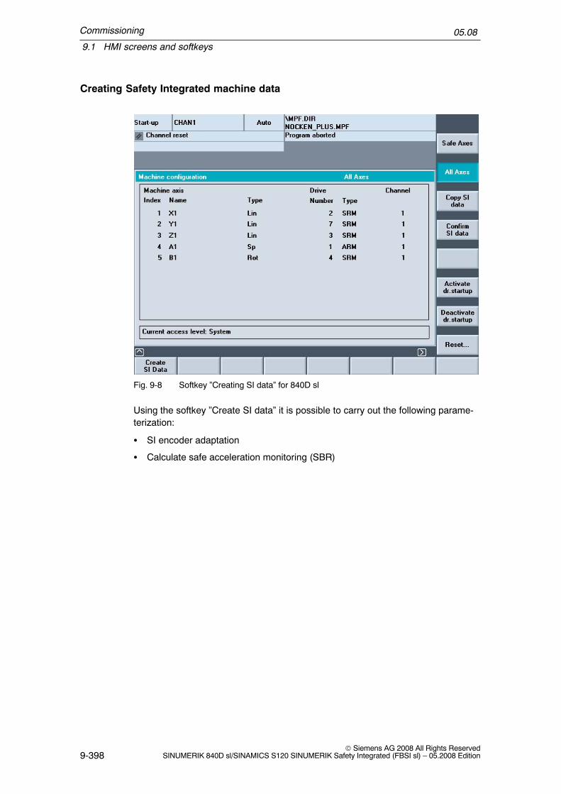
Commissioning
9.1 HMI screens and softkeys
05.08
9-398© Siemens AG 2008 All Rights Reserved
SINUMERIK 840D sl/SINAMICS S120 SINUMERIK Safety Integrated (FBSI sl) – 05.2008 Edition
Creating Safety Integrated machine data
Fig. 9-8 Softkey ”Creating SI data” for 840D sl
Using the softkey ”Create SI data” it is possible to carry out the following parame-terization:
� SI encoder adaptation
� Calculate safe acceleration monitoring (SBR)

Commissioning
9.1 HMI screens and softkeys
05.08
9-399© Siemens AG 2008 All Rights ReservedSINUMERIK 840D sl/SINAMICS S120 SINUMERIK Safety Integrated (FBSI sl) – 05.2008 Edition
SI encoder adaptation
A list is created comparing the actual values of the relevant MD and Safety MD.Using the softkey ”SI drive parameters”, the display can be changed over to thecorresponding drive parameters.
Fig. 9-9 Softkey ”SI encoder adaptation” for 840D sl
By pressing the softkey ”Calculate SI encoder data”, a parameterizing recommen-dation for the safety MD and parameters is determined and displayed. Further, alist that shows the actual values of the corresponding machine data is created.
When configuring two encoders, the following rules apply:
� The first encoder is always the encoder for the drive
� The second encoder is always the encoder for the NCK
� $MA_ENC_INPUT_NR[0]=1
� $MA_ENC_INPUT_NR[1]=2

Commissioning
9.1 HMI screens and softkeys
05.08
9-400© Siemens AG 2008 All Rights Reserved
SINUMERIK 840D sl/SINAMICS S120 SINUMERIK Safety Integrated (FBSI sl) – 05.2008 Edition
Fig. 9-10 Defining ”SI encoder adaptation” for 840D sl
The list is transferred into the corresponding SI machine data and SINAMICS pa-rameters using the softkey ”Accept”. They are rejected with ”Abort”. The user canalso adapt the values that have been determined.
The settings must be saved using the softkey ”Confirm SI data” (see e.g. Fig.9-8).
The axis assignment is described in Chapter 9.2 ”Procedure when commissioningthe system for the first time” under Step 3.

Commissioning
9.1 HMI screens and softkeys
05.08
9-401© Siemens AG 2008 All Rights ReservedSINUMERIK 840D sl/SINAMICS S120 SINUMERIK Safety Integrated (FBSI sl) – 05.2008 Edition
SI safe acceleration monitoring (SBR)
Using the softkey ”SI safe acceleration monitoring”, a window is displayed with thecurrent settings for the axis and the associated drive.
Fig. 9-11 SI safe acceleration monitoring for 840D sl
The softkey ”Calculate SBR tol.” leads to the window where a decision can bemade whether the calculation of the tolerance of the safe acceleration monitoringcan be agreed (”Accept” softkey) or the operation is cancelled (”Abort” softkey).Also here, the user can adapt the recommendation.
The settings must be saved using the softkey ”Confirm SI data” (see e.g. Fig.9-8).
The equations from Chapter 6.4 ”Safe acceleration monitoring (SBR)” are used asbasis to calculate the SBR tolerance. A tolerance of 20% is added to the value de-termined in this fashion.
With ”Accept” the calculated value for the safe acceleration monitoring is trans-ferred into machine data 36948: $MA_SAFE_STOP_VELO_TOL and parameterp9548: SI motion SBR.

Commissioning
9.1 HMI screens and softkeys
05.08
9-402© Siemens AG 2008 All Rights Reserved
SINUMERIK 840D sl/SINAMICS S120 SINUMERIK Safety Integrated (FBSI sl) – 05.2008 Edition
Fig. 9-12 SI safe acceleration monitoring for 840D sl

Commissioning
9.2 Procedure when commissioning the drive for the first time
05.08
9-403© Siemens AG 2008 All Rights ReservedSINUMERIK 840D sl/SINAMICS S120 SINUMERIK Safety Integrated (FBSI sl) – 05.2008 Edition
9.2 Procedure when commissioning the drive for the first time
This Chapter describes the steps that are necessary to commission the safetyfunctions integrated in the system. For the safety functions integrated in thesystem, the ”safe standstill” (SH) safety function integrated in the drive can also beused. This is the reason that a minimum configuration of the safety functions inte-grated in the drive is always necessary. The SH function itself does not have to beenabled, but possibly a required brake control (SBC) must be parameterized.
Commissioning SH/SBC/SS1 via the terminal control is described in detail in Chap-ter 4 ”Safety functions integrated in the drive”.
It is advisable to commission the machine so that at least the axes can be moved.The safety monitoring functions can then be immediately tested after SI data hasbeen entered. This type of test is absolutely essential in order to detect any dataentry errors.
The following steps must be taken in the specified sequence to commission SIfunctions:
Note
If only the SH, SBC and SS1 functions are used, then commissioning is carriedout as described in the Chapter 4.6 ”Commissioning the SH, SBC and SS1functions”.
!Warning
From SINAMICS SW2.5 onwards, the following applies:In a system configuration, the firmware versions of the DRIVE–CLiQ componentscan only differ from the versions on the CF card, if either
a) the automatic upgrade/downgrade (parameter p7826) is deactivated, orb) components with a new firmware version can no longer be downgraded to thestatus of the version available on the CF card.
Scenario a) is not permitted when Safety Integrated is used. The automaticupgrade/downgrade must not be disabled when Safety Integrated is used.(automatic firmware update (p7826) must be equal to 1)
Scenario b) is only permissible if this combination has been explicitly approved bythe manufacturer.
Step 1:
Enable option
� Starting screen ”Commissioning/NC/Safety–Integrated”: Set the password (atleast the machine manufacturer password)

Commissioning
9.2 Procedure when commissioning the drive for the first time
05.08
9-404© Siemens AG 2008 All Rights Reserved
SINUMERIK 840D sl/SINAMICS S120 SINUMERIK Safety Integrated (FBSI sl) – 05.2008 Edition
� ”General machine data” screen:Set the options
Step 2:
Commissioning PROFIsafe (Chapter 7.2.5 ”Parameterizing PROFIsafe commu-nications (NCK)”) and the associated PROFIsafe I/O.
Commissioning the safe programmable logic (Chapter 7.3.4 ”Starting the SPL”).
Step 3:
In the screen ”Axis–specific machine data” set the function enable bits (MD 36901:$MA_SAFE_FUNCTION_ENABLE and MD 36902: $MA_SAFE_IS_ROT_AX) ofall axes for which the safety–related motion monitoring functions are to be used.Enter the monitoring clock cycle and check.
� ”General machine data” screen:Enter the factor for the monitoring clock cycle in data $MN_SAFETY_SYS-CLOCK_TIME_RATIO (see Chapter 5.1”Monitoring clock cycle” and Chapter5.2 ”Crosswise data comparison”).
� The actual monitoring time is immediately displayed in data$MN_INFO_SAFETY_CYCLE_TIME.
Note
Before the next NCK RESET is initiated, you must copy the actual monitoringclock cycle to parameter p9500 ”SI motion monitoring clock cycle” of the driveusing softkey ”Copy SI data” in the ”Drive configuration” screen.

Commissioning
9.2 Procedure when commissioning the drive for the first time
05.08
9-405© Siemens AG 2008 All Rights ReservedSINUMERIK 840D sl/SINAMICS S120 SINUMERIK Safety Integrated (FBSI sl) – 05.2008 Edition
Note on the axis assignment
Note
The drives must be assigned to the axis due to the degrees of freedom that existfor the PROFIdrive telegram configuring – also in the SI machine data.This is the reason that the recommendations when configuring the driveconfiguration also apply when configuring Safety Integrated:
� Using the standard configuration and the recommended logical basisaddresses in STEP7.
� No re–parameterization of the selected list of drive objects in drive parameterp0978.
Under these prerequisites, the following cases can occur:
a) If the drive assignment using machine data MD 30110:$MA_CTRLOUT_MODULE_NR, MD 30220: $MA_ENC_MODULE_NR[0/1] andMD 13050: $MN_DRIVE_LOGIC_ADDRESS was left at the standard value, thenalso the drive assignment in MD 36906: $MA_SAFE_CTRLOUT_MODULE_NRand MD 10393: $MN_SAFE_DRIVE_LOGIC_ADDRESS must not changed.
b) If the drive assignment was changed using the machine data MD 30110:$MA_CTRLOUT_MODULE_NR and MD 30220: $MA_ENC_MODULE_NR[0/1]then MD 36906: $MA_SAFE_CTRLOUT_MODULE_NR should be parameterizedto the same value as for MD 30110: $MA_CTRLOUT_MODULE_NR
c) If the drive assignment was made by replacing the logical drive addresses inMD 13050: $MN_DRIVE_LOGIC_ADDRESS, then the same marshalling shouldalso be made in MD 10393: $MN_SAFE_DRIVE_LOGIC_ADDRESS.Example: Drive 1 and 2 were exchanged by interchanging index 0 and 1 ofMD 13050. MD 13050[0] was parameterized to 4140 and MD 13050[1] wasparameterized to 4100. Then, Index 0 and 1 of MD 10393 must also beinterchanged, i.e. 10393[0] must be set to 6724 and MD 10393[1] must be setto 6700.
The user is provided with support when assigning axes under the HMI path”Commissioning/Drive system/Drive units/PROFIBUS connection”.
Commissioning
9.2 Procedure when commissioning the drive for the first time
05.08
9-406© Siemens AG 2008 All Rights Reserved
SINUMERIK 840D sl/SINAMICS S120 SINUMERIK Safety Integrated (FBSI sl) – 05.2008 Edition
Step 4:
Commissioning the SH/SBC/SS1 functions integrated in the drive.
Note
The parameters of the safety functions integrated in the drive have their ownpassword protection that is however de–activated before commissioning.In the SINUMERIK environment we recommend that this password protection isnot activated as the complete commissioning area is password protected.The procedure to change the SI password is described in Chapter 4.6.2”Procedure when commissioning SH, SBC and SS1”
� In the drive, the SI commissioning mode must be selected. If an attempt ismade to change the SI parameters integrated in the drive without being in thecommissioning mode, then the drive rejects this with a message. A prerequisitefor the commissioning mode is that the pulses have been cancelled for all of thedrives. For all drives, the commissioning mode is selected using the softkey”Activate drive commissioning” in the screen ”Safety Integrated”. When press-ing this softkey, from the HMI, 95 is written into every drive parameter p0010, if:– in the associated NC axis in MD 36901: $MA_SAFE_FUNCTION_ENABLE
has a value not equal to 0, or– in drive parameter p9501: ”SI enable safety–related functions” there is a
value not equal to 0.
� The user can pre–assign PROFIsafe addresses by clicking the softkey ”Acti-vate drive commissioning” using parameter p9810: SI PROFIsafe address(Motor Module).
� Parameterize the SH/SBC/SS1 functions that are integrated in the drive in the”Drive machine data” screen. These especially include:– Function enable, SBCalso possible– SH/SS1 function enable signals if the corresponding selection is to be made
using terminals (refer to Chapter 4 ”Safety Functions Integrated in theDrive”)
– PROFIsafe address, if not already set using the ”Activate drive commission-ing” softkey
– CRC via the parameters integrated in the drive (this is also realized usingthe ”Deactivate drive commissioning” softkey, see next point)
� Setting the CRC and saving the parameterization that was just carried out isperformed using the ”Deactivate drive commissioning” softkey.
Commissioning
9.2 Procedure when commissioning the drive for the first time
05.08
9-407© Siemens AG 2008 All Rights ReservedSINUMERIK 840D sl/SINAMICS S120 SINUMERIK Safety Integrated (FBSI sl) – 05.2008 Edition
Step 5:
Set the monitoring function for all of the axes to be safely monitored.
Enter the following in the specified sequence in the ”axis–specific machine data”screen:
1. Axis characteristics (rotary or linear axis)
2. Measuring–circuit assignment, i.e. which encoder will supply the safety actualvalue, what are the characteristics of this encoder and how it is mechanicallymounted.
3. Monitoring limit values and tolerances
4. Changeover and monitoring times
5. Stop responses after a monitoring function has responded
6. Assignment of safety–related inputs and outputs, i.e. which sources are supply-ing the control signals for the NC monitoring channel and where do the feed-back signals go (for the drive monitoring channel, this interlocking/logical as-signment must be programmed in the PLC).
Step 6:
Set the monitoring and save the data for all of the associated drives.Here, almost all data entered under Step 6 are again entered in the ”Drive machinedata” screen. When the softkey ”Copy SI data” in the ”Safety Integrated” screen ispressed, the settings from Step 5 are automatically entered, with the exception ofPoints 2 and 6. Point 2 cannot be copied because the drive always operates withthe motor encoder and for a two–encoder system, has other characteristic datathan the encoder evaluated from the NC. The 6th point is not applicable on thedrive side. The following operating steps are therefore involved:
1. Press the softkey ”Copy SI data” in the screen ”Safety Integrated”.
2. For each drive, enter the encoder configuration using the softkey ”Adapt SI en-coder”. At the same time, the data, copied under Point 1 in Step 6 can be sub-ject to a visual check.
3. Initiate an NCK and drive reset using the appropriate softkey. In this case, com-ponent IDs are also transferred from the drive to the NCK.
4. Press the softkey ”Acknowledge SI data” in the ”Drive configuration” screen.A dialog box describing the function of the softkey then appears: After acknowl-edging with ”OK”, the actual checksum of the safety–related data is then savedin both monitoring channels and monitored for changes from this point onwards.Further, drive data is automatically saved in a non–volatile fashion.
5. A dialog box is displayed on the screen requesting you to perform an accep-tance test. You must acknowledge this dialog box. Now carry out the NCK resetand drive reset that are listed.
6. Activate SPL protection.

Commissioning
9.2 Procedure when commissioning the drive for the first time
05.08
9-408© Siemens AG 2008 All Rights Reserved
SINUMERIK 840D sl/SINAMICS S120 SINUMERIK Safety Integrated (FBSI sl) – 05.2008 Edition
Step 7:
Issue a user agreement (see Chapter 5.4.4, ”User agreement”)
� The safe limit positions and safe cams are now activated (provided that theyhave been enabled, refer to Chapter 5.5, ”Enabling safety–related functions”).This step can be omitted if you do not wish to use either of these functions.
� The key–operated switch must be set to position 3 in order to issue a useragreement.
Step 8:
Carry out the acceptance test and enter in the logbook.
� A function test must be carried out for all of the enabled safe monitoring func-tions and for each axis/spindle. For suggestions on how to test activated SIfunctions, please refer to Chapter 9.5.2, ”Acceptance test” and 9.5 ”Acceptancereport”.
� The parameterization of all PROFIsafe I/O components should be checked us-ing a function test and checking the printout of the hardware configuration fromSIMATIC Step 7.
Step 9:
� Save all machine data using the ”Services” area. This data can be used to com-mission series equipment.
� Save (back–up) the complete SIMATIC Step 7 project.
!Warning
After the acceptance test has been completed, all illegal (old) MD files must beremoved from the Flashcard (to avoid confusion between old and new data).Data that corresponds to the acceptance test data must be backed–up (archived).
Step 10:
Delete (clear) the password in order to prevent the unauthorized change ofmachine data.

Commissioning
9.3 Series commissioning
05.08
9-409© Siemens AG 2008 All Rights ReservedSINUMERIK 840D sl/SINAMICS S120 SINUMERIK Safety Integrated (FBSI sl) – 05.2008 Edition
9.3 Series commissioning
The setting for the safety monitoring functions is automatically transferred withother data in the course of a normal series commissioning process. The followingsteps need to be taken in addition to the normal commissioning procedure:
1. Enter a user agreement
2. Carry out an acceptance test(individual monitoring functions must be randomly tested)
Sequence of operations for series commissioning
The following sequence of operations is recommended when commissioning seriesequipment:
� Download the data set for the series machine into the control.
� Adjust the absolute encoder.
� Carry out a power on.This ensures that any errors – i.e. deviations in the data content that may existbetween the NCK and drive – will be detected by the checksum check andcrosswise data comparison.Data must be checked if an error is detected. Cross check errors on the hard-ware–related cross checksums (Alarm 27032 with ID 1) or Alarm 27035 arenormal if the series commissioning data come from another machine.If an error is not detected, then data has not been changed and is identical tothe acceptance test data. The copy function may be used if data is subse-quently altered.
� Carry out random function tests.The tests are required for acceptance of the new machine.
Software/hardware upgrade
!Warning
Please carefully read the instructions in the relevant Update Manual beforeupdating the software.

Commissioning
9.4 Changing data
05.08
9-410© Siemens AG 2008 All Rights Reserved
SINUMERIK 840D sl/SINAMICS S120 SINUMERIK Safety Integrated (FBSI sl) – 05.2008 Edition
!Warning
From SINAMICS SW2.5 onwards, the following applies:In a system configuration, the firmware versions of the DRIVE–CLiQ componentscan only differ from the versions on the CF card, if either
a) the automatic upgrade/downgrade (parameter p7826) is deactivated, orb) components with a new firmware version can no longer be downgraded to thestatus of the version available on the CF card.
Scenario a) is not permitted when Safety Integrated is used. The automaticupgrade/downgrade must not be disabled when Safety Integrated is used.(automatic firmware update (p7826) must be equal to 1)
Scenario b) is only permissible if this combination has been explicitly approved bythe manufacturer.
9.4 Changing data
The user must enter the correct password before he can change the machine datafor SI functions to the system. After data for SI functions has been altered, a newacceptance test must be carried out on the SI function(s) involved and then re-corded and confirmed in the acceptance report.
Change report
Changes made to NCK machine data important for Safety Integrated are recordedin a display data. The times that these changes were made are displayed in axialMD 36996: $MA_SAFE_CONFIG_CHANGE_DATE[0...4].
This MD can neither be overwritten by manual entry nor by loading an MD archive.It can only be deleted by booting the control from the general reset mode (switchposition 1).
This data is updated when the following changes are made to the NCK machinedata:
� When a modified safety MD configuration is activated(NCK safety MD have been changed and acknowledged by correction of$MA_SAFE_DES_CHECKSUM).
� When MD $MA_SAFE_FUNCTION_ENABLE is changed from values not equalto zero to zero, or from zero to values not equal to zero. These changes meanthat the safety functionality of an axis is completely enabled/disabled. Otherchanges to MD $MA_SAFE_FUNCTION_ENABLE always change MD$MA_SAFE_ACT_CHECKSUM, which themselves have to be acknowledgedby changes to MD $MA_SAFE_DES_CHECKSUM.
Commissioning
9.4 Changing data
05.08
9-411© Siemens AG 2008 All Rights ReservedSINUMERIK 840D sl/SINAMICS S120 SINUMERIK Safety Integrated (FBSI sl) – 05.2008 Edition
� When MD $MA_SAFE_FUNCTION_ENABLE is changed by reducing thesafety option. If the scope of axial safety functions is enabled for more axesthan are set in the safety option data, the function enable for the excess num-ber of axes is automatically cancelled again when the control boots.
� Loading an MD archive that is different to the currently active NCK–MD set.
� When upgrading (corresponds to downloading an MD archive)
� Series commissioning (corresponds to downloading an MD archive)
Limitations
Changes to the MD configuration are only noted when the change becomes active,i.e. after altering MD $MA_SAFE_DES_CHECKSUM and a subsequent Power On.This MD is calculated – also for axes that were not released for Safety Integrated.

Commissioning
9.5 Acceptance test
05.08
9-412© Siemens AG 2008 All Rights Reserved
SINUMERIK 840D sl/SINAMICS S120 SINUMERIK Safety Integrated (FBSI sl) – 05.2008 Edition
9.5 Acceptance test
9.5.1 General information
The requirements associated with an acceptance test can be derived from the EUMachinery Directive. Presently IEC 22G WG 10 is working on a standard for ”func-tional safety”. This also includes a specific description of the requirements for anacceptance test. Accordingly, the machine manufacturer (OEM) is responsible forthe following:
� to carry out an acceptance test for safety–related functions and machine parts,and
� to issue an ”Acceptance certificate” that includes the results of the test.
When using the Safety Integrated function, the acceptance test is used to checkthe correct configuring of the SI monitoring functions used in the NCK, PLC anddrive. The test objective is to verify proper implementation of the defined safetyfunctions and of test mechanisms (forced checking procedure measures) and toexamine the response of specific monitoring functions to the explicit input of valuesoutside tolerance limits. This should be carried out for all safety functions, i.e. forthe axial monitoring functions, the SPL, the safety–related communication relation-ships, the safety–related I/O etc.
!Warning
The acceptance test is used to check that the safety functions have been correctlyparameterized. Using the acceptance test, potential configuring errors are to beidentified and the correct configuring documented.The measured values (e.g. distance, time) and the system behavior determined(e.g. initiating a specific stop) when carrying out the acceptance test are used tocheck the plausibility of the configured safety functions. The measured values thatare determined are typical and are not worst–case values. They represent thebehavior of the machine and the instant in time that the measurement is carriedout. These measurements cannot be used to derive maximum distances forover–travel.
!Warning
If machine data for SI functions is changed, a new acceptance test must becarried out for the modified SI function and recorded in the acceptance report.

Commissioning
9.5 Acceptance test
05.08
9-413© Siemens AG 2008 All Rights ReservedSINUMERIK 840D sl/SINAMICS S120 SINUMERIK Safety Integrated (FBSI sl) – 05.2008 Edition
Note
The acceptance test should also be carried out for the PROFIsafe I/O.
Information regarding carrying out the acceptance test
� Some of the standard NC monitoring functions, such as zero speed monitoring,software limit switches, etc. must be de–activated (monitoring limits must bemade less sensitive) before the acceptance test is carried out.The function sequences can be acquired and listed using the servo trace func-tion or using the D/A converter output.
� After the SPL has been commissioned the access authorization for the NCK–SPL (SAFE.SPF) via the HMI interface must be reduced to the manufacturer orservice level and documented in the acceptance report.
� Please refer to the information in Chapter 9.2, ”Procedure when commissioningfor the first time”.
� The acceptance report comprises checking the alarm displays and including thealarm reports in the overall acceptance report. In order to obtain reproducibleand comparable alarm displays, during the acceptance test, MD 10094:$MN_SAFE_ALARM_SUPPRESS_LEVEL must be set to 0 in order to avoidsuppressing alarm outputs.
� For SINUMERIK 840D sl, to document a test stop that has been carried out, itis sufficient to just log the test stop alarms of the NCK (27002); it is not abso-lutely necessary to log the test stop alarms of the SINAMICS S120 (C01798).
SINAMICS firmware versions
For SINUMERIK software releases 1.3 and 1.4/2.4, different firmware versions ofthe components involved in the safety functions (NCU, NX, Motor Modules, SensorModules, DRIVE–CLiQ motors) may be mixed without having to adapt the firm-ware versions.From SINUMERIK software release 1.5/2.5 onwards, the following applies:The firmware versions of the Motor Modules, Sensor Modules and DRIVE–CLiQmotors involved in the safety functions (these include integrated Sensor Modules)must be adapted to the SINAMICS firmware version of the NCU. This is performedautomatically during startup if parameter p9826 (firmware, automatic) is set to 1(default setting). When Safety Integrated is used, parameter p9826 (firmware,automatic) must be set to 1 – and must not be re–parameterized. During theacceptance test for Safety Integrated, the safety firmware versions of all MotorModules, Sensors Modules and DRIVE–CLiQ motors involved in the safety func-tions should be read out, logged and checked against the following list.http://support.automation.siemens.com/WW/view/de/28554461
Every line in the table represents a permissible combination of safety firmware ver-sions.
Commissioning
9.5 Acceptance test
05.08
9-414© Siemens AG 2008 All Rights Reserved
SINUMERIK 840D sl/SINAMICS S120 SINUMERIK Safety Integrated (FBSI sl) – 05.2008 Edition
Authorized person, acceptance report
All SI functions must be acceptance–tested by an authorized person and the testresults recorded in a test report. The report must be signed by the person who car-ried out the acceptance tests. The acceptance test report must be kept in the log-book of the particular machine.
In this context this is a person who is authorized by the machine manufacturer andwho has adequate professional training and knowledge of the safety functions inorder to conduct the acceptance test in a proficient manner.
Documentation, data archiving
In addition to the acceptance report, the following SI relevant data must be archived:NC machine dataDrive parametersPLC/NCK–SPL programS7 configuration
Necessity of an acceptance test
A full acceptance test (as described in this Chapter) must always be carried outwhen the functionality of Safety Integrated is commissioned for the first time on amachine.
Extended safety–related functionality, transferring the commissioned software toadditional series machines, modifications to the hardware, software upgrades etc.make it necessary to carry out the acceptance test – possibly with a reduced testscope.
In order to define a partial acceptance test it is first necessary to describe the indi-vidual parts of the acceptance test and then define logical groups that representthe components of the acceptance test.
Contents of the full acceptance test
DOCUMENTATON
Documentation of the machine incl. safety functions
1. Machine description (with overview)
2. Details about the control system
3. Configuration diagram
4. Function tableActive monitoring functions depending on the operating mode, the protectivedoors and other sensorsIdeally, this table should be the objective and result of the configuring work.
5. SI functions per axis
6. Information about the safety equipment

Commissioning
9.5 Acceptance test
05.08
9-415© Siemens AG 2008 All Rights ReservedSINUMERIK 840D sl/SINAMICS S120 SINUMERIK Safety Integrated (FBSI sl) – 05.2008 Edition
FUNCTION TEST PART 1General function check incl. checking the wiring/programming/configuring
7. Test the shutdown paths(test the forced checking procedure of the shutdown paths)
8. Test the external stops
9. Test the forced checking procedure of the inputs and outputs
10.Test the Emergency Stop and the safety circuits
11.Test all SPL switching states and associated input/output signals
12.Check the hardware configuration of the PROFIsafe I/O
FUNCTION TEST PART 2Detailed function test incl. checking the values of the individual SI functions used
13.Test the SI function ”safe operating stop” – SBH(in each case with evaluated measurement diagram and measured values)
14.Test the SI function ”safely reduced speed” – SG(in each case with evaluated measurement diagram and measured values)
15.Test the SI function ”safety–related output n < nx”(in each case with evaluated measurement diagram and measured values)
16.Test the SI function ”safe limit positions” – SE(in each case with evaluated measurement diagram and measured values)
17.Test the SI function ”safe cams” – SN(check using the diagnostics display or assigned SGAs or with the evaluatedmeasuring diagrams and measured values)
18.If necessary, test the SI function ”external stops”(in each case with evaluated measurement diagram and measured values)
19.Test the SI function ”SBC/SBT”(in each case with evaluated measurement diagram or measured values/PROFIsafe I/O)
COMPLETION OF THE REPORTA report of the commissioning status that was checked is generated with the ap-propriate counter–signatures
20.Check the SI machine data
21.Log the checksums (axis MD/SPL/PROFIsafe I/O)
22.Completing the NCK commissioning (protect synchronous actions)
23.Completing the commissioning of the PLC
24.Verify the data backup
25.Have the report countersigned

Commissioning
9.5 Acceptance test
05.08
9-416© Siemens AG 2008 All Rights Reserved
SINUMERIK 840D sl/SINAMICS S120 SINUMERIK Safety Integrated (FBSI sl) – 05.2008 Edition
APPENDIXReports/measurement records for FUNCTION TEST PART 1/2
Printouts of the hardware configuration from SIMATIC Step 7 for the PROFIsafe I/O
Alarm logs/servo trace measurements
Archive the following SI–relevant data:NC machine dataDrive parametersPLC/NCK–SPL programS7 configuration
Note
The template in the toolbox is only a recommendation.
An electronic template for the acceptance report is available:
– in the toolbox for SINUMERIK 840D sl– on DOConCD for SINUMERIK 840D sl– on the service CD for SINUMERIK 840D sl
The acceptance report is divided into the following sections:
– Plant/system description– Description of the safety functions– Test of safety functions
Acceptance report of the hardware configurationFor the PROFIsafe I/O, a printout of the hardware configuration from SIMATICStep 7 is required as acceptance report.
For this purpose, in Step 7:
– Open project
– Open hardware
– Select the station/print preview

Commissioning
9.5 Acceptance test
05.08
9-417© Siemens AG 2008 All Rights ReservedSINUMERIK 840D sl/SINAMICS S120 SINUMERIK Safety Integrated (FBSI sl) – 05.2008 Edition
Fig. 9-13 Print preview, Step 7
– Acknowledge with OK
The hardware configuration is now displayed, can be printed and then subse-quently checked.
Effect of the acceptance test for specific measures
Table 9-1 Scope of the acceptance test depending on specific measures
Measure Documentation Function testPart 1
Function testPart 2
Reportcompletion
The encoder systemhas been replaced(refer to Chap. 9.6)
No No check of safe ac-tual values andfunction of SE/SN(axis–specific)
Supplement,possibly newchecksums andcounter–signature
Replace an SMC,SME module(refer to Chap. 9.6)
Supplement,hardware data/configuration/software versiondata
No check of safe ac-tual values andfunction of SE/SN(axis–specific)
Supplement,possibly newchecksums andcounter–signature

Commissioning
9.5 Acceptance test
05.08
9-418© Siemens AG 2008 All Rights Reserved
SINUMERIK 840D sl/SINAMICS S120 SINUMERIK Safety Integrated (FBSI sl) – 05.2008 Edition
Table 9-1 Scope of the acceptance test depending on specific measures
Measure Reportcompletion
Function testPart 2
Function testPart 1
Documentation
Replace a motor withDRIVE–CLiQ(refer to Chap. 9.6)
Supplement,hardware data/configuration/software versiondata
No check of safe ac-tual values andfunction of SE/SN(axis–specific)
Supplement,possibly newchecksums andcounter–signature
Replace the NCU, Nxmotor module hard-ware
Supplement,hardware data/configuration/software versiondata
No Partially, if thesystem clockcycles or dynamicresponse havebeen changed(axis–specific)
Supplement,possibly newchecksums andcounter–signature
Replace hardware/up-date software/reconfi-gure the PROFIsafe I/O
Supplement,hardware data/configuration/software versiondata
Yes
With a comment,limited to replacedcomponents/changed SW ver-sion/changedhardwareconfiguration
No Supplement,possibly newchecksums andcounter–signature
The software has beenupgraded(NCU/drive/PLC)
Supplement,version data
Yeswith note aboutthe new function
Yesif system clockcycles or accelera-tion characteristics(e.g. also jerk)have beenchanged orTest the new func-tionality
Supplement,possibly newchecksums andcounter–signature
The software has beenupgraded(HMI)
Possible sup-plement,SW version
No No No
An individual limit valuehas been changed(e.g. SG limit)
Supplement, SIfunctions peraxis
No Partialtest of thechanged limitvalue
Supplement,possibly newchecksums andcounter–signature
Function expanded(e.g. additional actua-tor, additional SGstage)
Supplement, SIfunctions peraxis or functiontable
Yes with noteif relevant – limitedto adapted parts
Partialtest of possibleadditional limit val-ues
Supplement,possibly newchecksums andcounter–signature
SPL change Supplement, SIfunctions peraxis or functiontable
Yes, test thepoints involved
No Supplement,possibly newchecksums andcounter–signature

Commissioning
9.5 Acceptance test
05.08
9-419© Siemens AG 2008 All Rights ReservedSINUMERIK 840D sl/SINAMICS S120 SINUMERIK Safety Integrated (FBSI sl) – 05.2008 Edition
Table 9-1 Scope of the acceptance test depending on specific measures
Measure Reportcompletion
Function testPart 2
Function testPart 1
Documentation
Data transferred toadditional machineswith series commis-sioning
Possibly sup-plement, ma-chine descrip-tion (check theSW version)
Yes with note No, for identicaldata
NoNo, if identicaldata (check thechecksums)
Note: If the results of function test, Part 2 are taken from another identical machine, then this is the soleresponsibility of the machine manufacturer and should be appropriately commented in the acceptancereport.
9.5.2 Conventional acceptance test
Procedure of the conventional acceptance test
Safety function Test initiated by Function checkedusing
Represented using
Forced checking proce-dure of the shutdownpaths
Test stop initiated e.g.by reducing the test stoptime or separate key
Switching operations atthe SGE/SGA
Alarm log 27002 axisTest stop running
C01798 test stop run-ning (this is not abso-lutely required)
Diagnostics display Diagnostics screen SIstatus
Servo trace SGE/SGA Decoded using servotrace bit graphics
Sequence of the teststop routine for externalstops
Test stop initiated e.g.by reducing the test stoptime or separate key
Servo trace SGE/SGA De–coded using servotrace bit graphics
Diagnostics display Diagnostics screen SIstatus
Drive interface PLC Trace Sinucom NC trace
Forced checking proce-dure of the input/outputperipherals (e.g. Emer-gency Stop)
Test stop initiated e.g.by reducing the test stoptime or separate key
Disconnect the feed-back signal contacts orjumper an SPL input
User error message
Stop D is initiated
Configuring/hardwareconfiguration of thePROFIsafe I/O
SPL Diagnostic displays,behavior of the SPL andI/O terminals, printout ofthe hardware configura-tion from SIMATICStep 7
Printout of the hardwareconfiguration fromSIMATIC Step 7

Commissioning
9.5 Acceptance test
05.08
9-420© Siemens AG 2008 All Rights Reserved
SINUMERIK 840D sl/SINAMICS S120 SINUMERIK Safety Integrated (FBSI sl) – 05.2008 Edition
Safety function Represented usingFunction checkedusing
Test initiated by
Test the safety–relatedfunctions (according tothe function table)
Use the safety–relatedsensors
Diagnostics display Diagnostics screen SIstatus
Safe operating stop(SBH)
Exceed the SBH limit bysetting MD 36933 to 0%operating mode, JOGtraversing keys
Servo trace:(actual speed, active en-coder/and actual value,active encoder)
the marker functionalityof the servo trace
Safely reduced speed(SG)
Exceed the SG limit bysetting MD 36933 to 0%operating mode, JOGtraversing keys
Servo trace:(actual speed, active en-coder/and actual value,active encoder)
the marker functionalityof the servo trace
SGA ”n < nx” Exceed the speed nx Servo trace:
(SGE/SGA and actualspeed, active encoder)
the marker functionalityof the servo traceDe–coded using bitgraphicsTrace Sinucom NC trace
Safe software limitswitches (SE)
Pass the positive andnegative limit switches
Change the SW limitswitch
Servo trace:(actual speed, active en-coder/and actual value,active encoder)
the marker functionalityof the servo trace
Safe software cams(SN)
Pass individual campositions
Servo trace (SGE/SGA) the marker functionalityof the servo trace
Diagnostics display De–coding using bitgraphics
Drive interface PLC Trace Sinucom NC trace
SBC/SBT Test stop initiated e.g.by reducing the test stoptime or separate key
Servo trace:(actual value active en-coder, torque)
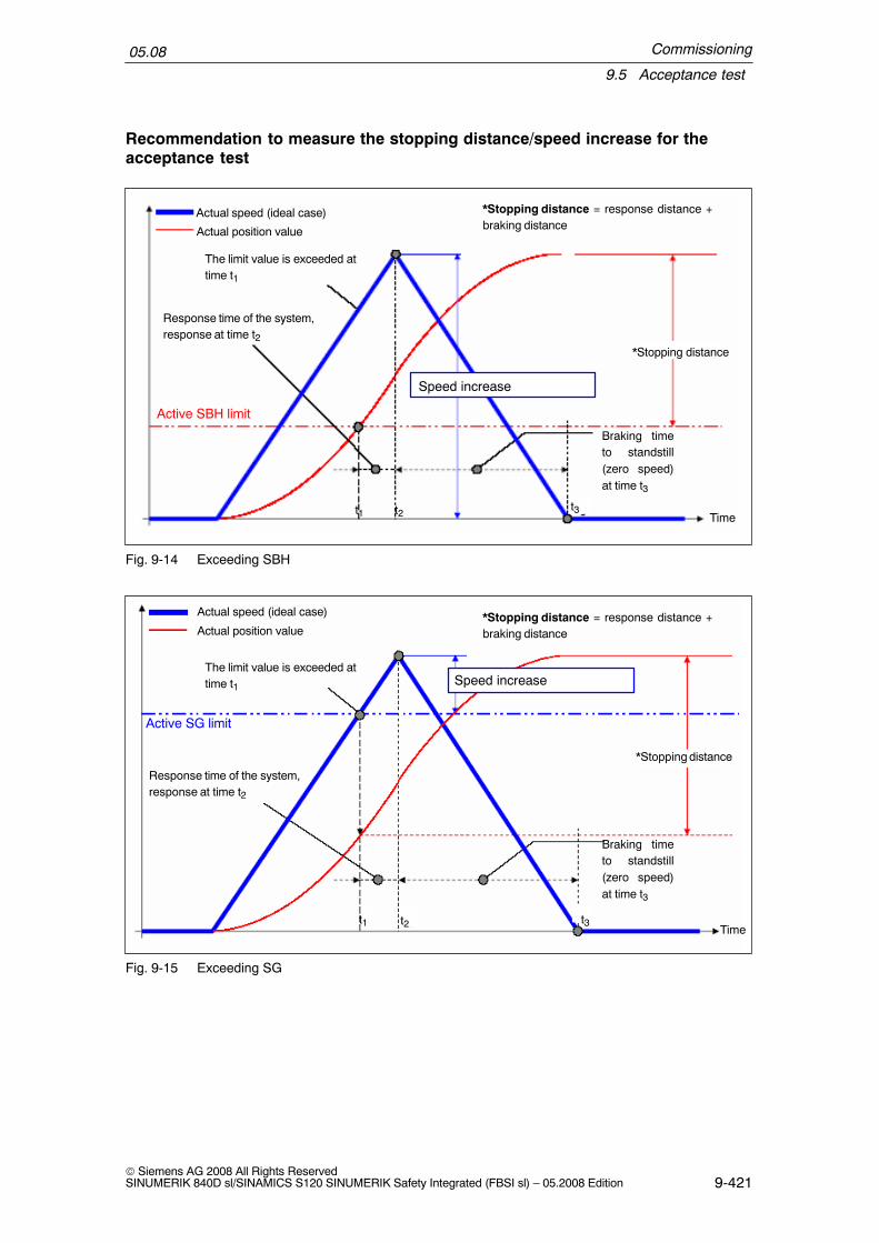
Commissioning
9.5 Acceptance test
05.08
9-421© Siemens AG 2008 All Rights ReservedSINUMERIK 840D sl/SINAMICS S120 SINUMERIK Safety Integrated (FBSI sl) – 05.2008 Edition
Recommendation to measure the stopping distance/speed increase for theacceptance test
Actual speed (ideal case)
Actual position value
*Stopping distance = response distance +braking distance
*Stopping distance
Time
Active SBH limit
Speed increase
Response time of the system,response at time t2
The limit value is exceeded attime t1
Braking timeto standstill(zero speed)at time t3
t2t1 t3
Fig. 9-14 Exceeding SBH
Actual speed (ideal case)
Actual position value*Stopping distance = response distance +braking distance
*Stopping distance
Time
Active SG limit
Speed increase
Response time of the system,response at time t2
The limit value is exceeded attime t1
Braking timeto standstill(zero speed)at time t3
t3t2t1
Fig. 9-15 Exceeding SG

Commissioning
9.5 Acceptance test
05.08
9-422© Siemens AG 2008 All Rights Reserved
SINUMERIK 840D sl/SINAMICS S120 SINUMERIK Safety Integrated (FBSI sl) – 05.2008 Edition
Actual speed (ideal case)
Actual position value
*Stopping distance = response distance +braking distance
*Stopping distance
Time
SE limit
Speed increase
Response time of the system,response at time t2
The limit value is exceeded attime t1
Braking timeto standstill(zero speed)at time t3
t2t1 t3
Fig. 9-16 Exceeding SE
9.5.3 Acceptance test support
In order to make it easier to carry out the acceptance test and standardize this,there is the function ”Acceptance test support” in the SinuCom NC commissioningtool”.
The objective of this acceptance support is to control the creation and administra-tion of an acceptance report and prepare and carry out the required test steps us-ing the appropriate operator actions via the operator interface. The test steps thatare required as part of the acceptance test are not completely automatically exe-cuted but are controlled by a skilled operator. This operator must carry out themeasures, associated with the test step, at the system being tested. The accep-tance test support provides the following:
� Support when documenting the active monitoring functions and monitoring limitvalues by reading out the appropriate machine data.
� Support when documenting the checksum values.
� Standardization of the procedure when carrying out the test, following a pre–de-fined test list.
� The time and resources required for testing are reduced by preparing test pro-cedures within the system, automatic trace and evaluation techniques and ittakes less time to acknowledge SI alarms that are output.

Commissioning
9.5 Acceptance test
05.08
9-423© Siemens AG 2008 All Rights ReservedSINUMERIK 840D sl/SINAMICS S120 SINUMERIK Safety Integrated (FBSI sl) – 05.2008 Edition
Software requirements
The acceptance test report function is based on the interaction between the NCK/drive and the SinuCom NC operator interface. This means that if this function isused, these components must have a certain minimum software version.
SinuCom NC software Version 7.2 SP1NCU system software Version 1.3
The basic functionality of the SinuCom NC software is explained within the scopeof its own documentation. This documentation also provides information about thesteps when handling the acceptance test support function, a description of thescreen forms and the menu prompting. This is the reason that this is not handled inthis documentation.
References: Commissioning/Service Tool SINUMERIK SinuCom NC (INC)
Scope of the test list
The test steps of the SI acceptance test, supported by the system, is based on theprevious test execution and comprises the following steps:
Designation Purpose of the test step
General information
Overview Document the machine details (e.g. manufacturer, machine type,...)
Check the forced checking procedure measures
Shutdown paths Test the forced checking procedure of the shutdown paths for theNCK and drive. (logging NCK Alarm 27002 is sufficient.)
External stops Test the forced checking procedure of the (that are being used) exter-nal stop responses.
Qualitative function checks
Emerg. stop Test the internal Emergency Stop functionality when executed viaexternal stop responses and the response to the external SPL I/O.
Function inter–relationships Test all of the states relevant for the safety functions that should befirst documented within the scope of a function table or similar (inter-dependency of sensor signals, positions, modes). In this case, thefollowing should be taken into account – the active monitoring func-tion for SI–monitored axes (internal safety functions) and the switch-ing state of safety–related external SPL output peripherals (I/O).
Quantitative function checks
SBH (safe operating stop) Test the response when provoking that the SBH limit values areviolated and define associated characteristic quantities/parameters.
SG (safely reduced speed) Test the response when provoking that the SG limit values areviolated and define associated characteristic quantities/parameters.
SE (safe software limit switches) Test the response when provoking that the SE limit value is violatedand define associated characteristic quantities/parameters.
SBT When the brake is closed, the drive generates an additional torquethat must not result in any axis motion.

Commissioning
9.5 Acceptance test
05.08
9-424© Siemens AG 2008 All Rights Reserved
SINUMERIK 840D sl/SINAMICS S120 SINUMERIK Safety Integrated (FBSI sl) – 05.2008 Edition
Designation Purpose of the test step
Completion
Done The test results are saved and downloaded.The acceptance report is generated based on the test results thathave been determined.
SI acceptance test
The following rule applies with the start of the SI acceptance test:
� The alarm suppression possibly set in MD 10094 $MN_SAFE_ALARM_SUPPRESS_LEVEL is not taken into account.
Test step, motion monitoring
With the start of a test step of the motion monitoring (e.g. SBH, SG) the followingconditions apply:
� Alarm ”Acceptance test mode active” NCK (Alarm No. 27007) and drive (FaultNo. C01799) are output.
� The setpoint velocity limiting set using MD 36933 $MA_SAFE_DES_VELO_LIMIT is de–activated. This allows the axis to be traversedin spite of the fact that the SBH monitoring is active or a traversing speedgreater than the actual SG monitoring without having to change the selectedreference (setpoint) speed limiting.
� SI power on alarms can be temporarily acknowledged with a reset so that afteran SBH response has been tested for an axis, an NCK reset does not have tobe initiated for the fault acknowledgement. This involves the acknowledgmentcriteria for the following alarms:
Alarm No. NCK Fault No. drive Alarm text
27010 C01707 Tolerance for safe operating stop exceeded
27023 C01701 STOP B initiated
27024 C01700 STOP A initiated
� Traversing motion is possible in spite of the external Stop C/D. This means thatit is also possible to test the active SBH monitoring state that results from anexternal Stop.
� An active stop in another axis does not result in a traversing inhibit for the axisbeing tested – also for the setting MD 36964 $MA_SAFE_IPO_STOP_GROUP= 0 for this axis.
� When traversing the axes using the JOG buttons, then the set speed limits areignored – such as e.g. MD 32020 $MA_JOG_VELO – and the G0 value is acti-vated as effective limit value (maximum axis speed).

Commissioning
9.5 Acceptance test
05.08
9-425© Siemens AG 2008 All Rights ReservedSINUMERIK 840D sl/SINAMICS S120 SINUMERIK Safety Integrated (FBSI sl) – 05.2008 Edition
� The single–channel software limit switches (set positions, refer to MD 36100 toMD 36130) are de–activated when testing SE. This means that an axis canpass these software limit switches without having to change the associated ma-chine data.
Prerequisites for the test step motion monitoring
A test step of the motion monitoring becomes active under the following conditions:
� There is no active SI power on alarm for the axis to be tested.
� The pulses of the axis to be tested are enabled.
� JOG is active as NC operating mode.
� The SI monitoring function selected when carrying out the test step is active,i.e. if for example the SG2 test is selected as test, then if SG1 is active, the ac-ceptance test mode is not active.
� Both monitoring channels (NCK, drive) allow the mode to be activated. Thestate that is assumed is subject to a crosswise data comparison between theNCK and drive.
A test step is cancelled by the following conditions:
� As a result of an NCK Reset
� When an internal timer value expires, that defines the maximum time that thestate can be active.This timer value is set in the following machine dataMD 36958 $MA_SAFE_ACCEPTANCE_TST_TIMEOUT (NCK) and parameterp9558: SI motion, acceptance test mode, time limit.
Trace techniques
A test is carried out prompted step–by–step using the SinuCom NC operator inter-face. There are various trace techniques, which can be used to confirm and log asto whether the test was successfully completed.
Text entry by the operatorA table or cell for the user documentation is provided for the test. This should thenbe completed corresponding to the specifications. In addition to how the test is initi-ated, the text entry includes, e.g. a description of test situations and responses orsimilar.
Alarms that occur are automatically loggedSpecific system and user alarms expected for the test step that are automaticallylogged after the data trace function has been started. After the appropriate datahas been traced, the selection of alarms to be logged can be reduced to thosealarms that are relevant for the specific test step.

Commissioning
9.5 Acceptance test
05.08
9-426© Siemens AG 2008 All Rights Reserved
SINUMERIK 840D sl/SINAMICS S120 SINUMERIK Safety Integrated (FBSI sl) – 05.2008 Edition
Internal signal trace functionThe SinuCom NC internal trace function is started when the data trace is startedand the signals, relevant for the specific test step, recorded. The trace is eitherautomatically ended or the user ends it for some tests (external stops, EmergencyStop).
Specific NC machine data must be set in order that the trace function can be used.This prepares the appropriate resources for the function. The values to be setshould be taken from the SINUMERIK SinuCom NC start–up tool.
Basic operating information and instructions
� The operator is prompted, step–by–step when carrying out a test. The followinglimitations/constraints must be observed, especially for those tests that use theinternal trace function:
If a traversing direction has been selected, then this must also be taken intoaccount for the subsequent task. The reason for this is that the trigger condi-tion for the automatic data acquisition and evaluation is based on this direc-tion data
A procedure is initiated to activate the trace function using the button <startdata acquisition>. This can take several seconds. The signal is only acquiredafter the appropriate feedback has been received in a message box.
If the trace has to be manually terminated, then this step should, if at all pos-sible, be made directly after the last expected signal change that is relevantfor the trace. This ensures that the relevant area is optimally displayed in thesubsequent trace display.
� For each test step, the operator must decide as to whether the test was suc-cessfully carried out. He should make this decision based on traced and deter-mined data and test situations that have been carried out and documented.This can be confirmed after the test has been carried out by selecting the ap-propriate results.
� The test list, provided and supported by SinuCom NC includes the basic teststeps to be carried out. Depending on the machine configuration, several testsmay not be necessary for the particular machine. This can be selected in thebasic screen of the test step. Further, there are test cases, that are required forthe machine but are not (or still not) included within the scope of the test list,e.g. measuring the braking travel when a light barrier is obstructed, or similar.These tests should still be manually executed.
� When generating the acceptance certificate, for documentation purposes, datais automatically retrieved from some machine data (SI limit values, checksums,hardware information).Further, the results of the tests that were carried out are incorporated in thedocument. The report is structured the same as the document that was pre-viously manually created. Some sections, such as for example, the machineoverview, function table of the configured safety functions etc., that are notstandardized, are still manually incorporated in the document at a later date.

Commissioning
9.6 Replacing a motor or encoder
05.08
9-427© Siemens AG 2008 All Rights ReservedSINUMERIK 840D sl/SINAMICS S120 SINUMERIK Safety Integrated (FBSI sl) – 05.2008 Edition
9.6 Replacing a motor or encoder
!Warning
After hardware and/or software components have been changed or replaced, it isonly permissible to boot the system and activate the drives when the protectivedevices are closed. Personnel shall not be present within the danger zone.
Depending on the change or replacement, it may be necessary to carry out a new,partial or complete acceptance test (see Chapter 9.5 Acceptance test).Before persons may re–enter the hazardous area, the drives should be tested toensure that they exhibit stable behavior by briefly moving them in both the plusand minus directions (+/–).It is especially important to carefully observe this for high–dynamic linear andtorque motors.
!Warning
After the measuring system has been replaced – regardless of whether it is adirect or an indirect system – the relevant axis must be re–calibrated.
Description
The following information essentially refers to replacing a motor encoder. The limi-tations that apply as well as the procedures are essentially the same when replac-ing a direct measuring system.
When service is required (motor defective or encoder defective), it might be neces-sary to completely replace the motor or just the motor encoder.
In this case, the motor encoder must be re–calibrated. This influences the behaviorof Safety Integrated if the functionality ”safe limit positions” or ”safe cams” havebeen activated for the axis in question, i.e. the axis has the status ”safely refer-enced”. Depending on which motor measuring system is used, it might be neces-sary to select a different procedure.
The procedure for replacing a motor with absolute value encoder and to replace amotor with incremental encoder are described in the following text. The end of theChapter discusses 2–encoder systems and encoder modules.
Limitations
As mentioned above, the functionality ”safe limit positions” or ”safe cams” is activefor the axis in question.

Commissioning
9.6 Replacing a motor or encoder
05.08
9-428© Siemens AG 2008 All Rights Reserved
SINUMERIK 840D sl/SINAMICS S120 SINUMERIK Safety Integrated (FBSI sl) – 05.2008 Edition
The user agreement is set for the axis, i.e. the axis has had the status ”safely ref-erenced” at least once – the actual position value of the NC and the SI actual val-ues (axis/drive) have been appropriately calibrated.
”Safe limit positions” or ”Safe cams” have been able to be used.A motor or motor encoder has to be replaced under these conditions.
Replacing a motor with absolute value encoder
In order to set–up the encoder, the offset between the machine zero and the zeroof the absolute encoder was determined.
The calibrated state is identified by the control usingMD 34210: ENC_REFP_STATE = 2.
The important factor when replacing a motor (also without Safety Integrated) is thata defined position reference can be established with respect to the mechanicalparts of the machine. For example, by mounting and removing the motor at a de-fined mechanical position or appropriately re–calibrating the system after the motorhas been replaced.
After the old motor has been removed and the new motor installed, another actualposition value is read by the new absolute value encoder (there is no longer a de-fined reference to the correctly calibrated actual position value).
Therefore the following error profile appears when the control boots:
Alarm 27001 Axis <name of the axis> fault in a monitoring channel, Code 1003,values: NCK x, drive y.
The comparison between the saved stop position and the actual position indicatesa larger deviation than that specified in MD 36944: $MA_SAFE_REFP_POS_TOLor parameter p9544: ”SI motion, actual value comparison tolerance (referencing)”
The alarm results in a STOP B followed by a STOP A (safe pulse cancellation) forthe axis involved.
The user agreement is also cancelled. This means that the axis loses the status”safely referenced” in connection with the Alarms 27000/C01797 axis <name of theaxis> not safely referenced.
The actual position value supplied by the new motor encoder has no reference tothe mechanical system. This means that the absolute value encoder must be re–aligned and set–up at this point.
Note
A safety acceptance report is generally not required after a motor has beenreplaced.
Commissioning
9.6 Replacing a motor or encoder
05.08
9-429© Siemens AG 2008 All Rights ReservedSINUMERIK 840D sl/SINAMICS S120 SINUMERIK Safety Integrated (FBSI sl) – 05.2008 Edition
Re–calibration procedure
1. Carry out an NCK reset
!Warning
After the NCK–Reset, the axis can be traversed again. Alarms 27000/C01797”Axis not safely referenced” are still present and indicate that the functions ”safelimit positions” and ”safe cams” are not active in this state. For example, if ”safelimit positions” is being used as a substitute for hardware limit switches, then it isimportant to note that at this time, the safe limit positions are not functional!
2. Move the axis to the reference position after first setting MD 34010REFP_CAM_DIR_IS_MINUS according to the approach direction. (34010should be set to 1 if the axis is moved in the negative (minus) direction to thereference position.)
3. MD 34100: Set REFP_SET_POS to the actual value of the reference position.
4. MD 34210: Set ENC_REFP_STATE = 1 to activate the calibration.
5. Select the axis that is to be calibrated on the machine control panel and pressthe RESET key on the machine control panel.
6. Select the JOG/REF mode, enable the axis feed.
7. The calibration process must be initiated with traversing key + or – according toMD 34010: REFP_CAM_DIR_IS_MINUS and the approach direction to thereference position. (Backlash has been moved through).
8. The axis does not traverse. Instead, the offset between the correct actualvalue (reference position) and the actual value – supplied by the encoder – isentered in MD 34090: REFP_MOVE_DIST_CORR. The actual value appears inthe basic screen and the axis signals ”referenced”. The value 2 is entered inMD 34210 as result.Example:MD 34010=1 (minus) and the reference position was approached in the nega-tive (minus) direction. This means that the ”–” key must also be pressed on themachine control panel.
9. When the absolute value encoder has been re–calibrated (MD 34210 from 1 –>2), the axis changes over into the ”referenced” state. At this time, the new validactual position is accepted as the safe actual values (axis and drive).
10.Finally, with the JOG/REF machine mode active, on the HMI the ”user agree-ment” softkey must be pressed and the user agreement for the axis involvedmust be reset. Alarms 27000/C01797 disappear and the functions ”safe limitposition” and ”safe cams” are safely active again.

Commissioning
9.6 Replacing a motor or encoder
05.08
9-430© Siemens AG 2008 All Rights Reserved
SINUMERIK 840D sl/SINAMICS S120 SINUMERIK Safety Integrated (FBSI sl) – 05.2008 Edition
Replacing a motor with incremental encoder
The same conditions apply as when replacing a motor with absolute encoder.
To calibrate the encoder, a reference point approach has been set up, e.g. withreference point cams. This means that after the zero mark has been passed whenleaving the cam, the reference point is approached according to the offsets in34080 REFP_MOVE_DIST and 34090 REFP_MOVE_DIST_CORR – and thevalue of the reference point is set in MD 34100: REFP_SET_POS. After the refer-encing operation, Alarm messages 27000/C01797 ”axis not safely referenced”disappear and the functions ”safe limit positions” and ”safe cams” are safely active.
The important factor when replacing a motor (also without Safety Integrated) is thata defined position reference can be established with respect to the mechanicalparts of the machine. For example, by mounting and removing the motor at a de-fined mechanical position or appropriately re–calibrating the system after the motorhas been replaced. At this instant in time, Alarms 27000/C01797 still do not disap-pear; they only disappear after the user agreement has been set.
After the old motor has been removed and the new motor installed, the followingprocedure is recommended:
Re–calibration procedure
1. Boot the control or carry out an NCK reset
2. If the JOG/REF machine mode is active on the HMI, the ”user agreement” soft-key must be pressed and the user agreement for the axis involved is withdrawnto avoid Alarm 27001 Axis <name of the axis> fault in a monitoring channel,Code 1003, values: NCK x, drive y
3. After the system has booted, the JOG/REF mode is selected and the feedenable for the axis is issued. Carry out a reference point approach for the axisinvolved.

Commissioning
9.6 Replacing a motor or encoder
05.08
9-431© Siemens AG 2008 All Rights ReservedSINUMERIK 840D sl/SINAMICS S120 SINUMERIK Safety Integrated (FBSI sl) – 05.2008 Edition
Note
The error at a reference point approach is no more than one revolution of themotor (difference between two zero marks). This offset is usually not critical for themechanical parts of the machine. If problems arise with the traversing limitsbecause of the type of reference point approach, then for example, set the offsetvalues in MD 34080 /34090 to non–critical values.
Alarms 27000/C01797 ”Axis not safely referenced” are still present and indicatethat the functions ”safe limit positions” and ”safe cams” are not active in this state.For example, if ”safe limit positions” is being used as a substitute forhardware limit switches, then it is important to note that at this time, thesafe limit positions are not functional!
After completion of the reference point approach, the axis goes into the”referenced” status. However, because of the zero mark offset between theencoders, the reference position still has to be calibrated, i.e. the positionreference with respect to the mechanical system must be re–established. Thesystem is calibrated after measuring the difference – usually in MD 34080REFP_MOVE_DIST or 34090 REFP_MOVE_DIST_CORR.
4. After the reference point has been re–calibrated, the reference point approachmust be re–initiated. The axis changes over into the ”referenced’” state. At thistime, the reference point value is taken over as the safe actual value for theaxis and drive.
5. Finally, with the JOG/REF machine mode active, on the HMI the ”user agree-ment” softkey must be pressed and the user agreement for the axis involvedmust be reset. Alarms 27000/C01797 disappear and the functions ”safe limitposition” and ”safe cams” are safely active again.
Comments about 2–encoder systems
Case A1st measuring system: Incremental motor measuring system2nd measuring system: Absolute direct measuring systemThe 2nd position measuring system (DBAx 1.5 = 0, DBAx 1.6 =1) is selected viathe axis interface as the active measuring system.
In this case, motor replacement is straightforward because the NC reference pointposition is only supplied with values from the 2nd measuring system (DMS).
Case B1st measuring system: Absolute motor measuring system2nd measuring system: Incremental direct measuring systemThe 1st position measuring system (DBAx1.5 = 1, DBX 1.6 =0) is selected as theactive measuring system via the axis interface when the system boots. This is formonitoring purposes. A changeover is then made to the 2nd position measuringsystem (DBAx 1.5 = 0, DBX 1.6 =1).
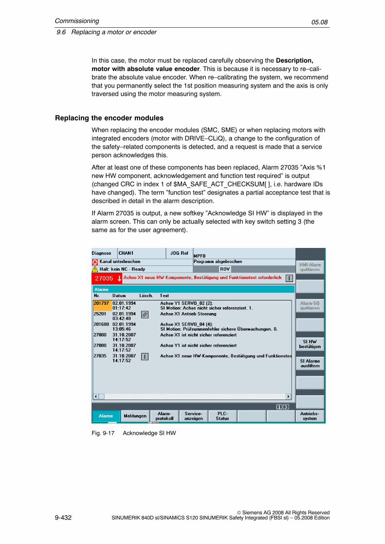
Commissioning
9.6 Replacing a motor or encoder
05.08
9-432© Siemens AG 2008 All Rights Reserved
SINUMERIK 840D sl/SINAMICS S120 SINUMERIK Safety Integrated (FBSI sl) – 05.2008 Edition
In this case, the motor must be replaced carefully observing the Description,motor with absolute value encoder. This is because it is necessary to re–cali-brate the absolute value encoder. When re–calibrating the system, we recommendthat you permanently select the 1st position measuring system and the axis is onlytraversed using the motor measuring system.
Replacing the encoder modules
When replacing the encoder modules (SMC, SME) or when replacing motors withintegrated encoders (motor with DRIVE–CLiQ), a change to the configuration ofthe safety–related components is detected, and a request is made that a serviceperson acknowledges this.
After at least one of these components has been replaced, Alarm 27035 ”Axis %1new HW component, acknowledgement and function test required” is output(changed CRC in index 1 of $MA_SAFE_ACT_CHECKSUM[ ], i.e. hardware IDshave changed). The term ”function test” designates a partial acceptance test that isdescribed in detail in the alarm description.
If Alarm 27035 is output, a new softkey ”Acknowledge SI HW” is displayed in thealarm screen. This can only be actually selected with key switch setting 3 (thesame as for the user agreement).
Fig. 9-17 Acknowledge SI HW

Commissioning
9.6 Replacing a motor or encoder
05.08
9-433© Siemens AG 2008 All Rights ReservedSINUMERIK 840D sl/SINAMICS S120 SINUMERIK Safety Integrated (FBSI sl) – 05.2008 Edition
After the softkey is selected, the following message is displayed on the HMI:
Fig. 9-18 Acknowledge SI HW, step 2
After acknowledging with OK, the actual checksums SAFE_ACT_CHECKSUM[1]for all of the axes are copied to the reference checksum SAFE_DES_CHECK-SUM[1] and a recommendation is given to power on the control. This is carried outby pressing OK.
After the system has successfully booted, the user must carry out the measures ofthe function test just acknowledged in the HMI messages or in Alarm 27035, i.e.
– Re–calibration of the actual value encoder
– Check the SI actual value acquisition: Speeds, traversing direction, absoluteposition (if required, set the user agreement)
– Document the new checksum value in SAFE_ACT_CHECKSUM[1] and thelast entry in the change history in MD SAFE_CONFIG_CHANGE_DATE[0]
– Document the hardware and software version data of the new component
Alternatively, Alarm 27035 can be acknowledged using the softkey ”AcknowledgeSI data” and the softkey ”Reset...”.
The user can suppress the automated internal actual value check by resetting the”user agreement” – therefore requesting that the axis is re–calibrated with theappropriate user agreement.

Commissioning
9.6 Replacing a motor or encoder
05.08
9-434© Siemens AG 2008 All Rights Reserved
SINUMERIK 840D sl/SINAMICS S120 SINUMERIK Safety Integrated (FBSI sl) – 05.2008 Edition
Space for your notes
10-435© Siemens AG 2008 All Rights ReservedSINUMERIK 840D sl/SINAMICS S120 SINUMERIK Safety Integrated (FBSI sl) – 05.2008 Edition
Diagnostics
Note
Not all of the HMI functions shown are available in all of the HMI versions (HMIEmbedded, HMI sl, HMI Advanced).
10.1 Troubleshooting procedure
� The alarms that have been activated in response to an error are output in the”DIAGNOSIS – ALARMS” display. When required, the safety alarms can besuppressed in the diagnostics display using the ”Filter out SI alarms” softkey.
� For Alarm 27090 ”Error for crosswise data comparison NCK–PLC”, the cause ofthe error (the incorrect SPL variable) is displayed in the alarm output.
� For Alarm 27254 ”PROFIsafe: F module, error on channel”, the input/outputchannel with error for modules belonging to the ET 200 series, is displayed inthe alarm output.
� For Alarm 27001 ”Defect in a monitoring channel”, the fine error code is alsodisplayed in the alarm output.
� For Alarm C01711 ”SI motion defect in a monitoring channel” the fine error codeis displayed in the alarm output. In the screen ”Commissioning – machine data– drive MD”, using parameter r9725: ”SI motion diagnostics STOP F”, thecause of the alarm can be read out.
� The current crosswise data comparison error code of the drive monitoring chan-nel is displayed in the diagnostics screen ”Status SI” in line ”Stop F code value”.
� For Alarms F01611/F30611 ”Defect in a monitoring channel”, the fine error codeis displayed in the alarm output. The current error search of this alarm is addi-tionally displayed in parameters r9795/r9895.
Note
Different error codes may be displayed for the NCK and drive monitoring channels.
10

Diagnostics
10.1 Troubleshooting procedure
05.08
10-436© Siemens AG 2008 All Rights Reserved
SINUMERIK 840D sl/SINAMICS S120 SINUMERIK Safety Integrated (FBSI sl) – 05.2008 Edition
10.1.1 Service displays
� Upon activation of the ”Service SI” softkey, the following information blocksabout SI–related data are displayed on the HMI for the selected axis:– Status SI (selected per default)– SI configuration– Cam SGA– SGE/SGA– SPL
Status SI
Fig. 10-1 Status SI
The axis+, axis– vertical softkeys or direct selection are used to set the desiredaxis. The current axis is displayed in the top right half of the table.
Various states for both channels are displayed separately in the diagnosticsscreen.

Diagnostics
10.1 Troubleshooting procedure
05.08
10-437© Siemens AG 2008 All Rights ReservedSINUMERIK 840D sl/SINAMICS S120 SINUMERIK Safety Integrated (FBSI sl) – 05.2008 Edition
SI configuration
You can go to the SI configuration window by pressing the softkey ”SI configuration”.
Fig. 10-2 SI configuration
An overview of the safety options that have been set is displayed in the upper sec-tion of this diagnostics screen.
The safety checksums for the NCK–SPL and for the PROFIsafe I/O are displayedin the lower section of the window; further, the axial checksums from the NCK anddrive.

Diagnostics
10.1 Troubleshooting procedure
05.08
10-438© Siemens AG 2008 All Rights Reserved
SINUMERIK 840D sl/SINAMICS S120 SINUMERIK Safety Integrated (FBSI sl) – 05.2008 Edition
SGE/SGA
The SGE/SGA window is reached by pressing the softkey SGE/SGA”.
Fig. 10-3 Status display of SGE/SGA
The available signals are shown in the diagram above.
Fig. 10-4 shows the detailed status display of the safety–related input/output signals.
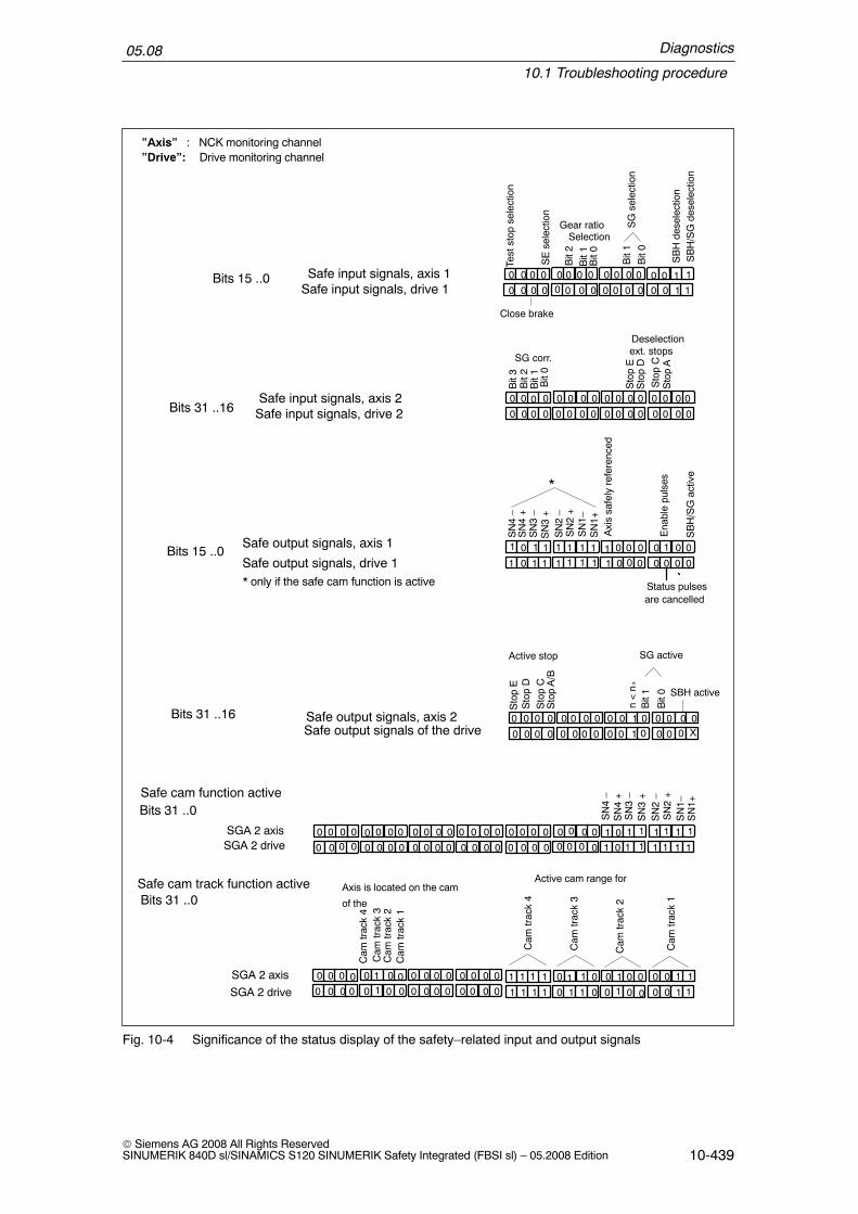
Diagnostics
10.1 Troubleshooting procedure
05.08
10-439© Siemens AG 2008 All Rights ReservedSINUMERIK 840D sl/SINAMICS S120 SINUMERIK Safety Integrated (FBSI sl) – 05.2008 Edition
SB
H/S
G d
esel
ectio
nS
BH
des
elec
tion
SG
sel
ectio
n
SE
sel
ectio
n
Test
sto
p se
lect
ion
Bit
0B
it 1
Bit
2
Bit
0
Bit
1
”Axis” : NCK monitoring channel”Drive”: Drive monitoring channel
Sto
p A
Sto
p C
Sto
p D
Deselectionext. stops
Safe input signals, drive 2
Safe input signals, axis 1Safe input signals, drive 1
Safe input signals, axis 2
Gear ratioSelection
Sto
p E
SN
4 –
SN
4 +
SN
3 –
SN
3 +
SN
2 –
SN
2 +
SN
1–S
N1+
Bit
0B
it 1
Bit
2B
it 3
SG corr.
Close brake
Cam
trac
k 1
Cam
trac
k 4
Cam
trac
k 3
Cam
trac
k 2
Safe output signals, axis 1
Safe output signals of the drive
SB
H/S
G a
ctiv
e
Status pulsesare cancelled
Axi
s sa
fely
ref
eren
ced
SBH active
n <
n
x
Safe output signals, drive 1
Safe output signals, axis 2
Ena
ble
puls
esSG active
Bit
1
Bit
0
Sto
p A
/BS
top
CS
top
D
Active stop
Bits 31 ..16
Sto
p E
Safe cam function active
Safe cam track function active Active cam range for
Bits 31 ..0
Bits 15 ..0
Bits 31 ..16
Bits 15 ..0
SGA 2 axisSGA 2 drive
SGA 2 axis
SGA 2 drive
Bits 31 ..0Axis is located on the cam
of the
Cam
trac
k 1
Cam
trac
k 2
Cam
trac
k 3
Cam
trac
k 4
11
0
000 0
0
0
110
0
00 0 00 0
0
0
000
00
0
0
00 00
0
0
0
0
0
0
0
0
0
0
0
0
0
0
0
0
0
0
0 0
0
0
0 00
00
00 0
0
00
0
0
0
0 00
0
0
0
0
1
0
0
011
0
00
0 0
0
0 0
00
00
0
0
1
11
1 1
1
1
1
1
1
1 1
X
1 1
1
1
0
0
0 0
00
00
0
0 00 0
000
1
1
1
1
1
1 10
0
0
0
0
0
0
0
0
0 0 1 1
1 11 1
11 1 111
1
11
0
0
0 000
0 00
0
0
0
0 0
00
0
0
0 00
0
0
0
0
0
0
0 0 00
0
0 0
00 0
00 0
0
000
0
00
0
0
0 0
00
00
0
0
0 00
0
0
0 0
0
000
011
11 1 1
1 1
11
1
100
0
0
0
0
0000
0
0
0
0
SN
4 –
SN
4 +
SN
3 –
SN
3 +
SN
2 –
SN
2 +
SN
1–S
N1+
*
* only if the safe cam function is active
Fig. 10-4 Significance of the status display of the safety–related input and output signals

Diagnostics
10.1 Troubleshooting procedure
05.08
10-440© Siemens AG 2008 All Rights Reserved
SINUMERIK 840D sl/SINAMICS S120 SINUMERIK Safety Integrated (FBSI sl) – 05.2008 Edition
Cam SGA
You can reach the corresponding windows for safe cam (Fig. 10-5) or safe camtrack (Fig. 10-6) using the ”Cam SGA” softkey.
Fig. 10-5 Cam SGA

Diagnostics
10.1 Troubleshooting procedure
05.08
10-441© Siemens AG 2008 All Rights ReservedSINUMERIK 840D sl/SINAMICS S120 SINUMERIK Safety Integrated (FBSI sl) – 05.2008 Edition
Fig. 10-6 Cam SGA

Diagnostics
10.1 Troubleshooting procedure
05.08
10-442© Siemens AG 2008 All Rights Reserved
SINUMERIK 840D sl/SINAMICS S120 SINUMERIK Safety Integrated (FBSI sl) – 05.2008 Edition
SPL
The SPL window is reached by pressing the softkey ”SPL”.
Fig. 10-7 Status display SPL
In the ”Variable” selection box, you can select:$A_INSE(P) corresponds to simultaneous selection of$A_INSE upper line, origin of the NCK and$A_INSEP lower line, origin of the PLCand effectively the same for the other variables:$A_OUTSE (P)$A_INSI (P)$A_OUTSI (P)$A_MARKERSI (P)$A_PLCSIIN$A_PLCSIOUT
The variables that have been selected and the associated bit areas are saved andare taken into account when subsequently selecting the screen.
Using the select key, the following formats can be selected in the variable rowsB BinaryH HexadecimalD Decimal, can be selected.
The selected format is applicable for the particular variable, as each variable canbe assigned an individual display format.Further, various SPL states are displayed.

Diagnostics
10.1 Troubleshooting procedure
05.08
10-443© Siemens AG 2008 All Rights ReservedSINUMERIK 840D sl/SINAMICS S120 SINUMERIK Safety Integrated (FBSI sl) – 05.2008 Edition
10.1.2 Diagnostics support by configuring your own extended alarm text
In order to upgrade the level of diagnostics information when an error occurs, cer-tain Safety Integrated system alarms can be supplemented by a freely–definableuser text. For instance, for hardware–related faults, supplementary informationsuch as input designation, circuit diagram identification number or similar can beincluded in the system alarm that is output.
This extended alarm text is based on the interaction between the NCK system soft-ware (that specifies the parameter that addresses the supplementary informationfor the alarm text) and the HMI software (that has to appropriately process thisparameter).
Dedicated extended alarm texts can be defined for the following Safety Integratedsystem alarms:
� General SPL crosswise data comparison errors (different status of the SPLvariables) Alarm 27090, error for crosswise data comparison, NCK–PLC
� Channel–related errors on the PROFIsafe module (only when using the ET 200PROFIsafe I/O)Alarm 27254 PROFIsafe: F module, error on channel
Prerequisites, HMI Advanced
The following entry is in the configuration file for the alarm server (file MBDDE.INI)in the section [Text files]:
File excerpt: mbdde.ini
[Textfiles]
NCK=f:\dh\mb.dir\aln_ ; Example : Standard entry
This means that all of the NCK alarms are defined in the file referenced after theNCK entry. The processing of an extended alarm text for the above specifiedalarms is prepared as part of this definition.
File excerpt: aln_gr.com
027090 0 0 ”Error for crosswise data comparison NCK–PLC, %1[%2], NCK:
%3; %4<ALSI>”
027254 0 0 ”PROFIsafe: F module %1, error in channel %2; %3<ALSI>”
Using the supplement %4<ALSI> (Alarm 27090) and %3<ALSI> (Alarm 27254),the possibility of providing an alarm text extension is defined for the alarm.
Principle of operation – extended alarm text
If Alarm 27090 or Alarm 27254 occurs, the NCK transfers an additional parametervalue to the HMI software (27090: %4; 27254: %3). This parameter has a definedvalue range. Each value can be uniquely assigned an extended alarm text.

Diagnostics
10.1 Troubleshooting procedure
05.08
10-444© Siemens AG 2008 All Rights Reserved
SINUMERIK 840D sl/SINAMICS S120 SINUMERIK Safety Integrated (FBSI sl) – 05.2008 Edition
Value range of the transfer parameter
000Parameterizing error detected when booting (different state active)Crosswise data comparison error, SPL protective mechanism: MD 11500 –DB18.DBX36.0Crosswise data comparison error, stop response for SPL error: MD 10097 –DB18.DBX36.1
001...064Error in system variables $A_INSE(P)[01...64] (Alarm 27090/Alarm 27254)The index value then results from a channel error signaled from the PROFIsafemodule(Alarm 27254), that is assigned the appropriate $A_INSE(P) variable (e.g. discrep-ancy error)
065...128Error in the system variables $A_OUTSE(P)[01...64] (Alarm 27090/Alarm 27254).This means, Alarm 27090 signals an internal logic error ($A_OUTSE(P) variablesdiffer) and Alarm 27254 signals a channel error signaled from the PROFIsafe mod-ule that is assigned to the appropriate $A_OUTSE(P) variable (e.g. short–circuitfault).
129...192Error in system variables $A_INSI(P)[01...64] (only alarm 27090)
193...256Error in system variables $A_OUTSI(P)[01...64] (only alarm 27090)
257...320Error in system variables $A_MARKERSI(P)[01...64] (only alarm 27090)
Definition of the extended text
The file, in which the extended texts are defined, is also declared in the configura-tion file for the alarm server (file MBDDE.INI) in the section [IndexTextFiles].
File excerpt: mbdde.ini
[IndexTextfiles]
ALSI=f:\dh\mb.dir\alsi_ ; Example : Standard entry
We recommend that this file for the extended text is located in the HMI user directory.
Every parameter can be assigned a dedicated text in this file, whereby the textentry is located in front of the associated parameter value (refer to the following fileexcerpt).
File excerpt: alsi_gr.com
000000 0 0 ”Parameterizing error MD11500/DB18.DBX36.0 or
MD10097/DB18.DBX36.1”
000001 0 0 ”User text $A_INSE(P)[01]”
..

Diagnostics
10.1 Troubleshooting procedure
05.08
10-445© Siemens AG 2008 All Rights ReservedSINUMERIK 840D sl/SINAMICS S120 SINUMERIK Safety Integrated (FBSI sl) – 05.2008 Edition
000064 0 0 ”User text $A_INSE(P)[64]”
000065 0 0 ”User text $A_OUTSE(P)[01]”
..
000128 0 0 ”User text $A_OUTSE(P)[64]”
000129 0 0 ”User text $A_INSI(P)[01]”
000192 0 0 ”User text $A_INSI(P)[64]”
000193 0 0 ”User text $A_OUTSI(P)[01]”
000256 0 0 ”User text $A_OUTSI(P)[64]”
000257 0 0 ”User text $A_OUTSI(P)[01]”
000320 0 0 ”User text $A_OUTSI(P)[64]”
The assigned user text is then displayed when Alarms 27090 or 27254 occur,referred to the associated SPL variable.

Diagnostics
10.1 Troubleshooting procedure
05.08
10-446© Siemens AG 2008 All Rights Reserved
SINUMERIK 840D sl/SINAMICS S120 SINUMERIK Safety Integrated (FBSI sl) – 05.2008 Edition
10.1.3 Servo trace bit graphics for Safety Integrated
General
The servo trace function is one of the measuring functions in the start–up area.Using the servo trace, for drive signals and NCK signals, measurements can bestarted by entering a measuring time and trigger conditions. The results of themeasurements are then graphically displayed. Two curves can be displayed in2 graphics. The results of the measurements can be saved in files. Further, thegraphics can be saved as bitmap file in the HMI data manager – or directly printedout.
Starting the servo trace
The servo trace is called in the operator area ”Commissioning/Optimization test/Servo trace”.
Signal selection
When selecting signals, axes and signal names can be selected from the appropri-ate lists for a maximum of 4 trace channels (trace 1 to trace 4). Trace 1 has aspecial significance – a signal must be selected in trace 1 otherwise when the PIservice is started using the vertical ”start” softkey, this is negatively acknowledgedfrom the NCK.

Diagnostics
10.1 Troubleshooting procedure
05.08
10-447© Siemens AG 2008 All Rights ReservedSINUMERIK 840D sl/SINAMICS S120 SINUMERIK Safety Integrated (FBSI sl) – 05.2008 Edition
Measuring parameters
For the measuring parameters, the measuring time, the trigger time, specificthresholds and various trigger signals can be set (e.g. a trigger from the part pro-gram). These settings are used to parameterize the PI services at the NCK usingthe vertical ”start” softkey. A measurement that has already been started can beinterrupted using the vertical ”stop” softkey. In this case, the NCK does not supplyany measured values.
Physical address
If the physical address entry is selected in the signal selection list, the vertical soft-key having the same name is activated. Using the input masks under this softkey,segment values and offset values of NCK system variables etc. can be specifiedand then measured.
It is possible to scroll through the axes and spindles in the application using thevertical ”Axis +” and ”Axis –” softkeys. The axis name or spindle name is includedin the selected selection list for the axis/spindle names.
Selecting SGE drive
The selection of the SI signal SGE drive (from the PLC) is shown in the following:

Diagnostics
10.1 Troubleshooting procedure
05.08
10-448© Siemens AG 2008 All Rights Reserved
SINUMERIK 840D sl/SINAMICS S120 SINUMERIK Safety Integrated (FBSI sl) – 05.2008 Edition
After the vertical ”start” softkey is pressed, the measurement is started on the NCKside. An appropriate note is output in the message line.
If the measurement cannot be started, appropriate error information is output. Thisinformation can be used to pinpoint the problem.
Display
Once the measurement has been completed, the results of the measurement canbe graphically displayed using the horizontal ”display” softkey:
Graphics
Two graphics (graphic 1 and graphic 2) are displayed. Each graphic can include upto two measured value curves that are color–coded (trace 1 in graphic 1: green,trace 2 in graphic 1: blue, trace 3 in graphic 2: green, trace 4 in graphic 2: blue)
Trace 1 and trace 2 are displayed in graphic 1, trace 3 and trace 4 in in graphic 2.The X axis of the graphics is the time axis and the Y axis is scaled in the physicalunits of the particular signal.
File functions
Measurement settings and the measured values of the servo trace functions canbe saved, downloaded or deleted using the horizontal softkey ”File functions”.

Diagnostics
10.1 Troubleshooting procedure
05.08
10-449© Siemens AG 2008 All Rights ReservedSINUMERIK 840D sl/SINAMICS S120 SINUMERIK Safety Integrated (FBSI sl) – 05.2008 Edition
10.1.4 Bit graphics for SI signals in the servo trace
Using the servo trace, individual bits can be selected from bit–coded SI signals andthe characteristic over time can be graphically displayed similar to a logic analyzer.Bit characteristics can be displayed as a function of time for 10 character channels(tracks).

Diagnostics
10.1 Troubleshooting procedure
05.08
10-450© Siemens AG 2008 All Rights Reserved
SINUMERIK 840D sl/SINAMICS S120 SINUMERIK Safety Integrated (FBSI sl) – 05.2008 Edition
Bit–coded SI signals
The bit–coded SI signals are principally sub–divided into two groups:
� SI signals where the system allocates the names of the bits (signals: SGE–NCK, SGA–NCK, SGE–PLC and SGA–PLC)
� SI signals where the user can freely select their names and default names areentered into an Ini file (F:\hmi_adv\ibsvtsi.ini). If the user wishes to change thedefault assignment, he can do this in the file hmi_adv\ibsvtsi.ini or using theappropriate forms in the operator interface.
These different bit–coded SI signals are parameterized on the operator interface.
The settings do not modify the measurement but only how the results of the mea-surement are actually displayed in the graphic.
No bit graphics are generated for SI signals that are not bit–coded.
The setting options are accessed using the vertical ”bit selection...” softkey:
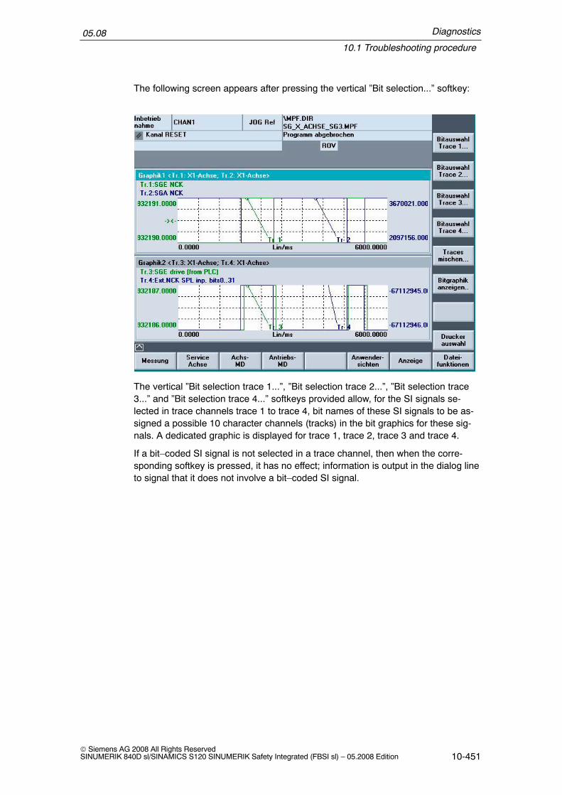
Diagnostics
10.1 Troubleshooting procedure
05.08
10-451© Siemens AG 2008 All Rights ReservedSINUMERIK 840D sl/SINAMICS S120 SINUMERIK Safety Integrated (FBSI sl) – 05.2008 Edition
The following screen appears after pressing the vertical ”Bit selection...” softkey:
The vertical ”Bit selection trace 1...”, ”Bit selection trace 2...”, ”Bit selection trace3...” and ”Bit selection trace 4...” softkeys provided allow, for the SI signals se-lected in trace channels trace 1 to trace 4, bit names of these SI signals to be as-signed a possible 10 character channels (tracks) in the bit graphics for these sig-nals. A dedicated graphic is displayed for trace 1, trace 2, trace 3 and trace 4.
If a bit–coded SI signal is not selected in a trace channel, then when the corre-sponding softkey is pressed, it has no effect; information is output in the dialog lineto signal that it does not involve a bit–coded SI signal.

Diagnostics
10.1 Troubleshooting procedure
05.08
10-452© Siemens AG 2008 All Rights Reserved
SINUMERIK 840D sl/SINAMICS S120 SINUMERIK Safety Integrated (FBSI sl) – 05.2008 Edition
Bit selection, trace 1...
In the example, the signal SGE–NCK has been read–in to graphic 1 for trace 1.The following screen is displayed when the vertical ”Bit selection trace 1...” softkeyis pressed:
The bits of this signal are consecutively numbered. Every bit is permanently as-signed an associated bit name. In the input box ”track”, by assigning a value in therange between 0..9 it is possible to define in which of the 10 character channels(tracks) the bit should be graphically displayed. In the example, for trace 1, bit 0SBH/SD deselection NCK is displayed in track 0 of the bit graphic. Bit 19 deselec-tion ext. Stop C NCK is displayed in track 9 of the bit graphic for trace 1.
The user is shown which track numbers have already been allocated (in the label”track number:” they have a blue background) If a track number is allocated twice,an error message is displayed. All of the signal bits are listed; bits that are notavailable are either designated as free or reserved. Using the scrollbar, it is pos-sible to scroll over the bit range from 0 to bit 31.
Starting values for the track assignments have been entered into the fileF:\hmi_adv\ibsvtsi.ini. If the user does not like these, then he can make the ap-propriate changes. These changes to the bit graphics become effective by press-ing the vertical ”Accept” softkey and are also transferred into the file hmi_adv\ibsvt-si.ini as new starting values. This means that they also apply for newmeasurements with this signal as default settings.
Using the vertical ”Abort” softkey, the screen is exited without accepting possiblechanges made to values.

Diagnostics
10.1 Troubleshooting procedure
05.08
10-453© Siemens AG 2008 All Rights ReservedSINUMERIK 840D sl/SINAMICS S120 SINUMERIK Safety Integrated (FBSI sl) – 05.2008 Edition
Bit selection, trace 2... to trace 4...
A similar procedure is also obtained for trace 2.. to trace 4 that, in this particularexample, contains the following signals:
Trace 2 SGE drive (from PLC)Trace 3 SGA–NCKTrace 4 SG drive (from PLC)
The handling is the same as described under bit selection, trace 1.
Mixing traces...
Using the vertical softkey ”Mix traces...”, the user can select individual bits of SIsignals from 4 traces and display these in the tracks as bit graphics for comparisonpurposes. This means that especially inputs and outputs of various SI signals canbe combined.
Result of the bit selection

Diagnostics
10.1 Troubleshooting procedure
05.08
10-454© Siemens AG 2008 All Rights Reserved
SINUMERIK 840D sl/SINAMICS S120 SINUMERIK Safety Integrated (FBSI sl) – 05.2008 Edition
10.1.5 Servo trace signals
The following states are made accessible via the trace functionality:
Table 10-1 Servo trace signals
System quantity Associated systemvariable
Updating
Safe actual position $VA_IS[axis] Monitoring clockcycle
Safe actual drive position – Axis CDC clockcycle
Axial SGE NCK – Monitoring clockcycle
Axial SGA NCK – Monitoring clockcycle
Axial SGE drive – OB1 clock cycle
Axial SGA drive – Monitoring clockcycle
Response ID for IPO0 = no STOP active1 = STOP F active2 = STOP E active3 = STOP D active4 = STOP C, B or A activePlease note! The values returned can deviate fromthis rule for the duration of the acceptance testmode.
– Monitoring clockcycle
Response ID for servo/drive0 = no STOP or STOP F, E, D active1 = STOP B active2 = STOP C active4 = STOP A activePlease note! The returned values can deviate fromthis rule for the duration of the acceptance test modeand the boot phase.
– Monitoring clockcycle
Result list 1 NCK – Monitoring clockcycle
Result list 1 drive – Axis CDC clockcycle
Result list 2 NCK – Monitoring clockcycle
Result list 2 drive – Monitoring clockcycle
Safety partial actual valuePosition change per monitoring clock cycle
– Monitoring clockcycle
Actual speed limit – Monitoring clockcycle

Diagnostics
10.1 Troubleshooting procedure
05.08
10-455© Siemens AG 2008 All Rights ReservedSINUMERIK 840D sl/SINAMICS S120 SINUMERIK Safety Integrated (FBSI sl) – 05.2008 Edition
Table 10-1 Servo trace signals
System quantity UpdatingAssociated systemvariable
Setpoint speed limit – Monitoring clockcycle
Actual value difference NCK drive – Axis CDC clockcycle
Current slip speed NCK drive – Axis CDC clockcycle
Current SBR limit value – Monitoring clockcycle
Ext. NCK–SPL interface inputs $A_INSED[1] IPO cycle
Ext. NCK–SPL interface inputs $A_INSED[2] IPO cycle
Ext. NCK–SPL interface outputs $A_OUTSED[1] IPO cycle
Ext. NCK–SPL interface outputs $A_OUTSED[2] IPO cycle
Int. NCK–SPL interface inputs $A_INSID[1] IPO cycle
Int. NCK–SPL interface inputs $A_INSID[2] IPO cycle
Int. NCK–SPL interface outputs $A_OUTSID[1] IPO cycle
Int. NCK–SPL interface outputs $A_OUTSID[2] IPO cycle
NCK–SPL markers $A_MARKERSID[1] IPO cycle
NCK–SPL markers $A_MARKERSID[2] IPO cycle
SPL timer 1 $A_TIMERSI[1] IPO cycle
SPL timer 2 $A_TIMERSI[2] IPO cycle
SPL timer 3 $A_TIMERSI[3] IPO cycle
SPL timer 4 $A_TIMERSI[4] IPO cycle
SPL timer 5 $A_TIMERSI[5] IPO cycle
SPL timer 6 $A_TIMERSI[6] IPO cycle
SPL timer 7 $A_TIMERSI[7] IPO cycle
SPL timer 8 $A_TIMERSI[8] IPO cycle
Ext. PLC–SPL interface inputs $A_INSEPD[1] SPL–CDC clockcycle
Ext. PLC–SPL interface inputs $A_INSEPD[2] SPL–CDC clockcycle
Ext. PLC–SPL interface outputs $A_OUTSEPD[1] SPL–CDC clockcycle
Ext. PLC–SPL interface outputs $A_OUTSEPD[2] SPL–CDC clockcycle
Int. PLC–SPL interface inputs $A_INSIPD[1] SPL–CDC clockcycle
Int. PLC–SPL interface inputs $A_INSIPD[2] SPL–CDC clockcycle
Int. PLC–SPL interface outputs $A_OUTSIPD[1] SPL–CDC clockcycle

Diagnostics
10.1 Troubleshooting procedure
05.08
10-456© Siemens AG 2008 All Rights Reserved
SINUMERIK 840D sl/SINAMICS S120 SINUMERIK Safety Integrated (FBSI sl) – 05.2008 Edition
Table 10-1 Servo trace signals
System quantity UpdatingAssociated systemvariable
Int. PLC–SPL interface outputs $A_OUTSIPD[2] SPL–CDC clockcycle
NCK–SPL markers $A_MARKERSIPD[1] SPL–CDC clockcycle
NCK–SPL markers $A_MARKERSIPD[2] SPL–CDC clockcycle
SPL timer 9 $A_TIMERSI[9] IPO cycle
SPL timer 10 $A_TIMERSI[10] IPO cycle
SPL timer 11 $A_TIMERSI[11] IPO cycle
SPL timer 12 $A_TIMERSI[12] IPO cycle
SPL timer 13 $A_TIMERSI[13] IPO cycle
SPL timer 14 $A_TIMERSI[14] IPO cycle
SPL timer 15 $A_TIMERSI[15] IPO cycle
SPL timer 16 $A_TIMERSI[16] IPO cycle
Cam SGA NCK – Monitoring clockcycle
SGA drive16 bit SGA from the drive
– Monitoring clockcycle
Cam SGA drive – Monitoring clockcycle
Actual value difference fine position – redundant coarseposition
– Monitoring clockcycle
Result list 3 NCK – Monitoring clockcycle
Result list 3, (drive) – Axis CDC clockcycle
Result list 4 NCK – Monitoring clockcycle
Result list 4, (drive) – Axis CDC clockcycle
Result list 5 NCK – Monitoring clockcycle
Result list 5, (drive) – Axis CDC clockcycle
Result list 6 NCK – Monitoring clockcycle
Result list 6, (drive) – Axis CDC clockcycle
Result list 7 NCK – Monitoring clockcycle
Result list 7, (drive) – Axis CDC clockcycle

Diagnostics
10.2 NCK safety alarms for SINUMERIK 840D sl
05.08
10-457© Siemens AG 2008 All Rights ReservedSINUMERIK 840D sl/SINAMICS S120 SINUMERIK Safety Integrated (FBSI sl) – 05.2008 Edition
10.2 NCK safety alarms for SINUMERIK 840D sl
Alarms for SINUMERIK 840D/SINAMICS S120
Detailed explanations of all alarms that are not described here can be found in thefollowing references for the SINUMERIK 840D system with SINAMICS S120:
References: /DA/ Diagnostics instructions SINUMERIK 840D/LH1/ SINAMICS S List Manual
Alarms for SINUMERIK Safety Integrated
The alarms that can occur in connection with the SI option are listed below:
14751 Channel %1 block%2 resources for motion synchronizing actionsnot sufficient (identifier: %3)
%1 = channel number%2 = block number%3 = identifier
To process motion synchronizing actions resources are required. Theyare configured via the machine data $MC_MM_IPO_BUFFER_SIZE,$MC_MM_NUM_BLOCKS_IN_PREP,$MC_MM_NUM_SAFE_SYNC_ELEMENTS,$MC_MM_NUM_SYNC_ELEMENTS. If these resources are insuffi-cient for executing the part program, then this alarm is issued. The pa-rameter %3 shows which resource has run out:Increase identifier <= 2: $MC_MM_IPO_BUFFER_SIZE or$MC_MM_NUM_BLOCKS_IN_PREP.Increase identifier > 2: $MC_MM_NUM_SYNC_ELEMENTS,$MC_MM_NUM_SAFE_SYNC_ELEMENTS.
Alarm displayInterface signals are set
Correct the part program or increase the resources.
20095 Axis %1 illegal torque, current torque %2
%1 = axis name, spindle number%2 = measured holding torque when selecting the brake test
The actually measured holding torque cannot be provided with the ex-isting parameterization of the brake test.
Alarm displayThe function test of the mechanical brake system is abortedThe PLC block FB11 for the sequence control to test the mechanicalbrake system is exited with a fault (fault detection = 2). This means thatthe request – ”start brake test” – isn’t even effective for the axis.
Parameter
Explanation
Response
Remedy
Parameter
Explanation
Response
Diagnostics
10.2 NCK safety alarms for SINUMERIK 840D sl
05.08
10-458© Siemens AG 2008 All Rights Reserved
SINUMERIK 840D sl/SINAMICS S120 SINUMERIK Safety Integrated (FBSI sl) – 05.2008 Edition
Check the parameterization for the brake test function: The torque forweight equalization in drive parameter p1532 should be approximatelythe same as the actual holding torque.The specified torque for the brake test in MD $MA_SAFE_BRAKET-EST_TORQUE must be set higher than the actual holding torque.
Clear the alarm with the Clear key or with NC–START.
20096 Axis %1 brake test aborted, additional info %2
%1 = axis name, spindle number%2 = fault information, based on $VA_FXS_INFO
The brake test has detected a problem. The additional information pro-vides details of the cause of the alarm. An explanation is provided inthe documentation about the system variables $VA_FXS_INFOSupplementary info:0: No additional information available1: Axis type is neither a PLC nor a command axis2: Limit position reached, motion stopped3: Abort using NC–RESET (key reset)4: Monitoring window exited5: Torque reduction rejected by drive6: PLC has withdrawn the enable signal
Alarm displayInterface signals are set.
Note the supplementary conditions of the brake test, refer to supple-mentary information.
Clear the alarm with the Clear key or with NC–START.
20097 Axis %1 incorrect traversing direction brake test
%1 = axis name, spindle number
As a result of the selected traversing direction, the brake test is carriedout for the existing load torque with an incorrect torque.
Alarm display
– Carry out the brake test in the other traversing direction– Adapt drive parameter p1532 more precisely to the actual situation.
This alarm only occurs – with the brake open – if the actual torquedeviates by more than 5% of parameter p1532
– Using MD $MA_SAFE_BRAKETEST_CONTROL, bit 0 = 1, activatethe automatic load torque determination at the beginning of thebrake test.
Clear the alarm with the Clear key or with NC–START.
Remedy
Programcontinuation
Parameter
Explanation
Response
Remedy
Programcontinuation
Parameter
Explanation
Response
Remedy
Programcontinuation

Diagnostics
10.2 NCK safety alarms for SINUMERIK 840D sl
05.08
10-459© Siemens AG 2008 All Rights ReservedSINUMERIK 840D sl/SINAMICS S120 SINUMERIK Safety Integrated (FBSI sl) – 05.2008 Edition
20149 Channel %1 block%2 motion synchronous action: Index invalid
%1 = channel number%2 = block number
When accessing a variable in the motion synchronous action, an invalidindex was used.Example: ...DO $R[$AC_MARKER[1]] = 100The error occurs if marker 1 has a higher value than the maximum per-missible R parameter number.
NC start inhibit in this channelInterface signals are setAlarm displayNC stop for alarm
Use a valid index.
Clear the alarm with the RESET key. Restart the part program.
27000 Axis %1 is not safely referenced
%1 axis number
There are two reasons for this alarm:– the user has still not acknowledged the machine position,– the machine position has not yet been verified through follow–up
referencing.Even if the axis is already referenced there is no acknowledgement thatreferencing has supplied the correct result. For example, incorrect re-sults can occur if the axis was moved after the control was powered–down – with the result that the stop position saved prior to powering–down is no longer correct. To ensure that this does not happen, theuser must acknowledge the displayed actual position after the first ref-erencing operation.After the user agreement has been set for the first time, the axis mustbe subsequently referenced each time that the control is booted (withabsolute encoders, this subsequent referencing is automatically exe-cuted). This procedure is carried out to verify the stop position savedprior to powering–down the control.The alarm display can be set using MD $MN_SAFE_ALARM_SUP-PRESS_LEVEL (MD>=3) so that the group alarm 27100 is displayedfor all SI axes.
Parameter
Explanation
Response
Remedy
Programcontinuation
Parameter
Explanation

Diagnostics
10.2 NCK safety alarms for SINUMERIK 840D sl
05.08
10-460© Siemens AG 2008 All Rights Reserved
SINUMERIK 840D sl/SINAMICS S120 SINUMERIK Safety Integrated (FBSI sl) – 05.2008 Edition
Alarm displayThe SGA ”axis safely referenced” is not set. SE is disabled if the safetyactual position has not yet been acknowledged by the user agreement.If the user agreement is set, SE remains active. The safe cams arecalculated and output, but their significance is limited because referenc-ing has not been acknowledged.
Move the axis to a known position, change to the ”referencing” modeand press the softkey ”Agreement”. Check the positions in the agree-ment screen at the machine. If these correspond to those expected atthe known position, confirm this using the toggle key. If the user agree-ment has already been set, re–reference the axis.The user agreement can only be changed in key–actuated switch set-ting 3 or after entering a password.
The alarm is no longer displayed when the alarm cause has been re-moved. No other operator actions are required
!Warning
If the axis has not been safely referenced and the user has not issued a useragreement, then the following applies:– the safe cams are still not safe– the safe limit positions are still not active
27001 Axis %1 error in a monitoring channel, Code %2, values:NCK %3, drive %4
%1 = axis number%2 = supplementary information, crosswise data comparison index%3 = supplementary information, comparison value, NCK%4 = supplementary information, comparison value, drive
The status of the safety–related monitoring functions are cyclically andmutually compared between the two monitoring channels (NCK anddrive). The comparison is carried out separately for each NCK/drivecombination.A criterion in a comparison list is compared between the NCK and drivein each monitoring clock cycle (MD 10091); the next criterion iscompared in the next monitoring clock cycle etc. Once the completecomparison list has been processed, the comparisons are processedagain from the start. The total comparison time to process the list isdisplayed in MD 10092 (factor x MD 10091 – the factor can differ de-pending on the SW version).
Response
Remedy
Programcontinuation
Parameter
Explanation

Diagnostics
10.2 NCK safety alarms for SINUMERIK 840D sl
05.08
10-461© Siemens AG 2008 All Rights ReservedSINUMERIK 840D sl/SINAMICS S120 SINUMERIK Safety Integrated (FBSI sl) – 05.2008 Edition
The ”Error in a monitoring channel” Alarm is only output if the mutualcomparison of the two monitoring channels detects a difference be-tween the input data or results of the monitoring. One of the monitoringfunctions no longer operates reliably.The crosswise comparison index, output under %2, is also known asSTOP F code. The STOP F code is also output in Alarm 27001 wherethe NCK detected a crosswise comparison error for the first time.The STOP F code of the drive (belonging to Alarm F30611) can betaken from the diagnostics screen or the drive parameter r9795. If adifference is detected at several comparison steps, then also severalSTOP F code values can be displayed, alternating, at these positions.There are fault profiles that are identified as a result of several compari-son operations of the comparison list. This means that the displayedSTOP F code value does not always provide a clear statement regard-ing the cause of the fault. The associated procedure is then explainedfor each of the individual fault codes.The following fault codes are possible:0No fault/error has been detected in this monitoring channel.For alarm 27001 this means that it was one of the subsequent alarms(follow–on alarms) of alarm F01711 – and the valid STOP F code valueis to be determined using the diagnostics display or the drive MD.1For the monitoring functions SBH, SG, SBR or SE, a different state hasoccurred between the NCK and drive. The actual status image (resultlist 1) is output from the NCK as supplementary input %3 (comparisonvalue, NCK) and the actual status image from the drive is output assupplementary info %4 (comparison value, drive). The two supplemen-tary infos are also saved in drive parameters r9710[0] and r9710[1].An example for evaluating the bit–coded result list is provided in thedescription of the drive machine data.RemedyThe difference in the states between the drive and NCK should bedetermined and the function involved should be investigated in moredetail.Example:State, NCK: SBH is active and okState, drive: SG1 is active and okThe fault is caused due to the fact that the SGE ”SBH deselection” iscontrolled differently. The signal source should be checked on both theNCK and drive sides. Generally, the different control (in operation) is aresult of a hardware failure associated with the sensor signal involved.In the commissioning phase, the cause can also be parameterization orprogramming errors.2For the monitoring function SN or n < nx, a different state has occurredbetween the NCK and drive.The actual status image of the NCK (result list 2) is output as supple-mentary info %3 (comparison value NCK) and the actual status image

Diagnostics
10.2 NCK safety alarms for SINUMERIK 840D sl
05.08
10-462© Siemens AG 2008 All Rights Reserved
SINUMERIK 840D sl/SINAMICS S120 SINUMERIK Safety Integrated (FBSI sl) – 05.2008 Edition
from the drive is output as supplementary info %4 (comparison value,drive). The two result lists are also written into as parameter r9711[0]and r9711[1]. An example for evaluating the bit–coded result list is pro-vided in the description of the drive parameter.RemedyThe difference in the states between the drive and NCK should be de-termined and the function involved should be investigated in more de-tail.3The difference between the safe actual value NCK and drive is greaterthan that set in MD 36942 $MA_SAFE_POS_TOL.When using the actual value synchronization, the difference of thespeed (determined based on the safety actual values) is greater thanthat set in MD 36949 $MA_SAFE_SLIP_VELO_TOL.RemedyCommissioning phase:The encoder evaluation for the NCK and drive is not correctly set –>correct the encoder evaluation.In operation:The actual values differ due to mechanical faults (transmission belts,traversing to mechanical limit, wear and tolerance windows that havebeen set too narrow, encoder faults...)–> check the mechanical design and the encoder signals4Not assigned.5The setting in MD 36901 $MA_SAFE_FUNCTION_ENABLE does notcorrespond with the associated drive parameter assignment.RemedyCopy SI data6The setting in MD 36931 $MA_SAFE_VELO_LIMIT[0] does not corre-spond with the associated drive parameter assignment.RemedyCopy SI data7The setting in MD 36931 $MA_SAFE_VELO_LIMIT[1] does not corre-spond with the associated drive parameter assignment.RemedyCopy SI data.8The setting in MD 36931 $MA_SAFE_VELO_LIMIT[2] does not corre-spond with the associated drive parameter assignment.RemedyCopy SI data.

Diagnostics
10.2 NCK safety alarms for SINUMERIK 840D sl
05.08
10-463© Siemens AG 2008 All Rights ReservedSINUMERIK 840D sl/SINAMICS S120 SINUMERIK Safety Integrated (FBSI sl) – 05.2008 Edition
9The setting in MD 36931 $MA_SAFE_VELO_LIMIT[3] does not corre-spond with the associated drive parameter assignment.RemedyCopy SI data.10The setting in MD 36930 $MA_SAFE_STANDSTILL_TOL does not cor-respond with the associated drive parameter assignment.RemedyCopy SI data.11The setting in MD 36934 $MA_SAFE_POS_LIMIT_PLUS[0] does notcorrespond with the associated drive parameter assignment.RemedyCopy SI data.12The setting in MD 36935 $MA_SAFE_POS_LIMIT_MINUS[0] does notcorrespond with the associated drive parameter assignment.RemedyCopy SI data.13The setting in MD 36934 $MA_SAFE_POS_LIMIT_PLUS[1] does notcorrespond with the associated drive parameter assignment.RemedyCopy SI data.14The setting in MD 36935 $MA_SAFE_POS_LIMIT_MINUS[1] does notcorrespond with the associated drive parameter assignment.RemedyCopy SI data.15The setting in MD 36936 $MA_SAFE_CAM_POS_PLUS[0] +MD 36940 $MA_SAFE_CAM_TOL does not correspond with theassociated drive parameter assignment.RemedyCopy SI data.16The setting in MD 36936 $MA_SAFE_CAM_POS_PLUS[0] does notcorrespond with the associated drive parameter assignment.RemedyCopy SI data.17The setting in MD 36937 $MA_SAFE_CAM_POS_MINUS[0] +MD 36940 $MA_SAFE_CAM_TOL does not correspond with theassociated drive parameter assignment.RemedyCopy SI data.

Diagnostics
10.2 NCK safety alarms for SINUMERIK 840D sl
05.08
10-464© Siemens AG 2008 All Rights Reserved
SINUMERIK 840D sl/SINAMICS S120 SINUMERIK Safety Integrated (FBSI sl) – 05.2008 Edition
18The setting in MD 36937 $MA_SAFE_CAM_POS_MINUS[0] does notcorrespond with the associated drive parameter assignment.RemedyCopy SI data.19The setting in MD 36936 $MA_SAFE_CAM_POS_PLUS[1] +MD 36940 $MA_SAFE_CAM_TOL does not correspond with theassociated drive parameter assignment.RemedyCopy SI data.20The setting in MD 36936 $MA_SAFE_CAM_POS_PLUS[1] does notcorrespond with the associated drive parameter assignment.RemedyCopy SI data.21The setting in MD 36937 $MA_SAFE_CAM_POS_MINUS[1] +$MA_SAFE_CAM_TOL does not correspond with the associated driveparameter assignment.RemedyCopy SI data.22The setting in MD 36937 $MA_SAFE_CAM_POS_MINUS[1] does notcorrespond with the associated drive parameter assignment.RemedyCopy SI data.23The setting in MD 36936 $MA_SAFE_CAM_POS_PLUS[2] +MD 36940 $MA_SAFE_CAM_TOL does not correspond with theassociated drive parameter assignment.RemedyCopy SI data.24The setting in MD 36936 $MA_SAFE_CAM_POS_PLUS[2] does notcorrespond with the associated drive parameter assignment.RemedyCopy SI data.25The setting in MD 36937 $MA_SAFE_CAM_POS_MINUS[2] +MD 36940 $MA_SAFE_CAM_TOL does not correspond with theassociated drive parameter assignment.RemedyCopy SI data.26The setting in MD 36937 $MA_SAFE_CAM_POS_MINUS[2] does notcorrespond with the associated drive parameter assignment.RemedyCopy SI data.

Diagnostics
10.2 NCK safety alarms for SINUMERIK 840D sl
05.08
10-465© Siemens AG 2008 All Rights ReservedSINUMERIK 840D sl/SINAMICS S120 SINUMERIK Safety Integrated (FBSI sl) – 05.2008 Edition
27The setting in MD 36936 $MA_SAFE_CAM_POS_PLUS[3]+ MD 36940 $MA_SAFE_CAM_TOL does not correspond with theassociated drive parameter assignment.RemedyCopy SI data.28The setting in MD 36936 $MA_SAFE_CAM_POS_PLUS[3] does notcorrespond with the associated drive parameter assignment.RemedyCopy SI data.29The setting in MD 36937 $MA_SAFE_CAM_POS_MINUS[3] +MD 36940 $MA_SAFE_CAM_TOL does not correspond with theassociated drive parameter assignment.RemedyCopy SI data.30The setting in MD 36937 $MA_SAFE_CAM_POS_MINUS[3] does notcorrespond with the associated drive parameter assignment.RemedyCopy SI data.31The settings in MD 36942 $MA_SAFE_POS_TOL. and MD 36949$MA_SAFE_SLIP_VELO_TOL do not correspond with the associateddrive parameter assignment.RemedyCopy SI data.32The setting in MD 36944 $MA_SAFE_REFP_POS_TOL does notcorrespond with the associated drive parameter assignment.RemedyCopy SI data.33The setting in MD 36951 $MA_SAFE_VELO_SWITCH_DELAY doesnot correspond with the associated drive parameter assignment.RemedyCopy SI data.34The setting in MD 36950 $MA_SAFE_MODE_SWITCH_TIME does notcorrespond with the associated drive parameter assignment.RemedyCopy SI data.35The setting in MD 36956 $MA_SAFE_PULSE_DISABLE_DELAY doesnot correspond with the associated drive parameter assignment.RemedyCopy SI data.

Diagnostics
10.2 NCK safety alarms for SINUMERIK 840D sl
05.08
10-466© Siemens AG 2008 All Rights Reserved
SINUMERIK 840D sl/SINAMICS S120 SINUMERIK Safety Integrated (FBSI sl) – 05.2008 Edition
36The setting in MD 36957 $MA_SAFE_PULSE_DIS_CHECK_TIMEdoes not correspond with the associated drive parameter assignment.RemedyCopy SI data.37The setting in MD 36952 $MA_SAFE_STOP_SWITCH_TIME_C doesnot correspond with the associated drive parameter assignment.RemedyCopy SI data.38The setting in MD 36953 $MA_SAFE_STOP_SWITCH_TIME_D doesnot correspond with the associated drive parameter assignment.RemedyCopy SI data.39The setting in MD 36954 $MA_SAFE_STOP_SWITCH_TIME_E doesnot correspond with the associated drive parameter assignment.RemedyCopy SI data.40The setting in MD 36961 $MA_SAFE_VELO_STOP_MODE does notcorrespond with the associated drive parameter assignment.RemedyCopy SI data.41The setting in MD 36962 $MA_SAFE_POS_STOP_MODE does notcorrespond with the associated drive parameter assignment.RemedyCopy SI data.42The setting in MD 36960 $MA_SAFE_STANDSTILL_VELO_TOL doesnot correspond with the associated drive parameter assignment.RemedyCopy SI data.43Stop response, memory test.44 – 57ExplanationFault codes 44–57 cannot be clearly assigned to a fault cause. For themonitoring functions that run internally (e.g. SG), monitoring limits areinternally generated that are referred to a monitoring clock cycle.Example:SG1 = 2000 mm/min, monitoring clock cycle = 12 msIf SG1 is active, then a check is made in every monitoring clock cycle(MCC) as to whether SG1 was exceeded.

Diagnostics
10.2 NCK safety alarms for SINUMERIK 840D sl
05.08
10-467© Siemens AG 2008 All Rights ReservedSINUMERIK 840D sl/SINAMICS S120 SINUMERIK Safety Integrated (FBSI sl) – 05.2008 Edition
This means that in MCC[n], based on the actual value, a positive andnegative actual value limit is defined that may not be exceeded inMCC[n+1] in order to still comply with SG1.SG1 = 2000 mm/min = 33.33 mm/s = 0.4 mm/MCC (for each 12 ms)If the axis moves more than 0.4 mm in a monitoring clock cycle, thenSG1 would be violated.The limit values, specified above, in MCC[n+1] are thenPositive: Position actual value (MCC[n]) + 0.4 mmNegative: position actual value (MCC[n]) –0.4 mmThe resulting monitoring limits (positive and negative) that are, in turndetermined independently for both monitoring channels (NCK anddrive) are also compared just like the safe actual positions (refer to faultcode 3). The comparison is for a difference < MD 36942$MA_SAFE_POS_TOL.If the difference is greater than MD 36942 $MA_SAFE_POS_TOL,then the appropriate fault code is output.The limit values are then re–generated and compared in every monitor-ing cycle independently of whether the associated monitoring functionis active or not.This means that there are three possible causes for this fault codegroup.
Causes and remedyPossible cause 1 (only when commissioning or changing the MD)The tolerance value for the monitoring function is set differently for theNCK and drive. This situation actually only occurs when commissioningthe system or making changes and is generally already covered by theprevious fault codes.Remedy: Set the relevant machine data the same.Possible cause 2 (in operation)The limit values are determined based on the actual value. This meansthat when the safe actual values of the NCK and drive differ then thelimit values are also different by the defined clearance –> i.e. the faultcode corresponds to the fault image of fault code 3. This can be deter-mined by checking the safe actual positions.Remedy: Refer to fault code 3.Possible cause 3 (in operation)The associated monitoring function is already active in a monitoringchannel – while in the other monitoring channel another monitoringfunction is still active. This is the case if the safe actual positions of theNCK and drive do not differ but instead there is an entry in drive param-eters r9710/r9711 (and the 1 appears in parameter r9725) –> i.e. thefault code corresponds to the fault profile of fault code 1. This can alsobe identified using the fault message if for %3 = supplementary infocomparison value NCK or %4 = supplementary info comparison valuedrive no real limit value is output but only the value of the calculatedtolerance (refer to the example above (SG1 = 2000 mm/min = 0.4 mm/monitoring clock cycle), a value of 400 would be displayed as 4%).Remedy: Refer to fault code 1.

Diagnostics
10.2 NCK safety alarms for SINUMERIK 840D sl
05.08
10-468© Siemens AG 2008 All Rights Reserved
SINUMERIK 840D sl/SINAMICS S120 SINUMERIK Safety Integrated (FBSI sl) – 05.2008 Edition
44Upper limit value for SG1 = position actual value + MD 36931$MA_SAFE_VELO_LIMIT[0] referred to a monitoring clock cycleRemedyRefer to Section 44–57 (hidden fault code 3 or 1)45Lower limit value for SG1 = position actual value – MD 36931$MA_SAFE_VELO_LIMIT[0] referred to a monitoring clock cycleRemedyRefer to Section 44–57 (hidden fault code 3 or 1)46Upper limit value for SG2 = position actual value + MD 36931$MA_SAFE_VELO_LIMIT[1] referred to a monitoring clock cycleRemedyRefer to Section 44–57 (hidden fault code 3 or 1)47Lower limit value for SG2 = position actual value – MD 36931$MA_SAFE_VELO_LIMIT[1] referred to a monitoring clock cycleRemedyRefer to Section 44–57 (hidden fault code 3 or 1)48Upper limit value for SG3 = position actual value + MD 36931$MA_SAFE_VELO_LIMIT[2] referred to a monitoring clock cycleRemedyRefer to Section 44–57 (hidden fault code 3 or 1)49Lower limit value for SG3 = position actual value – MD 36931$MA_SAFE_VELO_LIMIT[2] referred to a monitoring clock cycleRemedyRefer to Section 44–57 (hidden fault code 3 or 1)50Upper limit value for SG4 = position actual value + MD 36931$MA_SAFE_VELO_LIMIT[3] referred to a monitoring clock cycleRemedyRefer to Section 44–57 (hidden fault code 3 or 1)51Lower limit value for SG4 = position actual value – MD 36931$MA_SAFE_VELO_LIMIT[3] referred to a monitoring clock cycleRemedyRefer to Section 44–57 (hidden fault code 3 or 1)52Upper limit value for SBHPosition actual value (when SBH is activated) + MD 36930$MA_SAFE_STANDSTILL_TOL.RemedyRefer to Section 44–57 (hidden fault code 3 or 1)

Diagnostics
10.2 NCK safety alarms for SINUMERIK 840D sl
05.08
10-469© Siemens AG 2008 All Rights ReservedSINUMERIK 840D sl/SINAMICS S120 SINUMERIK Safety Integrated (FBSI sl) – 05.2008 Edition
53Lower limit value for SBHPosition actual value (when SBH is activated) – MD 36930$MA_SAFE_STANDSTILL_TOL.RemedyRefer to Section 44–57 (hidden fault code 3 or 1)54Upper limit value for n < nx (plus tolerance)Position actual value + MD 36946 $MA_SAFE_VELO_X (referred to amonitoring clock cycle) + MD 36942 $MA_SAFE_POS_TOL.RemedyRefer to Section 44–57 (hidden fault code 3 or 1)55Upper limit value for n<nxPosition actual value + MD 36946 $MA_SAFE_VELO_X (referred to amonitoring clock cycle).RemedyRefer to Section 44–57 (hidden fault code 3 or 1)56Lower limit value for n< nxPosition actual value – MD 36946 $MA_SAFE_VELO_X (referred to amonitoring clock cycle).RemedyRefer to Section 44–57 (hidden fault code 3 or 1)57Upper limit value for n < nx (plus tolerance)Position actual value + MD 36946 $MA_SAFE_VELO_X–(referred to amonitoring clock cycle) – MD 36942 $MA_SAFE_POS_TOL.RemedyRefer to Section 44–57 (hidden fault code 3 or 1)58There is a difference in the active request for an external STOP. Twofactors determine the resulting external STOP request for a monitoringchannel.� The STOP requested via the SGE interface� The STOP passed–through from the other monitoring channel
The STOP of the active request is specified as detailed fault code forthe NCK and drive.The following values are possible:0 = No Stop2 = Stop E3 = Stop D4 = Stop C7 = Stop A59The setting in MD 36932 $MA_SAFE_VELO_OVR_FACTOR[0] doesnot correspond with the associated drive parameter assignment.
Diagnostics
10.2 NCK safety alarms for SINUMERIK 840D sl
05.08
10-470© Siemens AG 2008 All Rights Reserved
SINUMERIK 840D sl/SINAMICS S120 SINUMERIK Safety Integrated (FBSI sl) – 05.2008 Edition
RemedyCopy SI data.60The setting in MD 36932 $MA_SAFE_VELO_OVR_FACTOR[1] doesnot correspond with the associated drive parameter assignment.RemedyCopy SI data.61The setting in MD 36932 $MA_SAFE_VELO_OVR_FACTOR[2] doesnot correspond with the associated drive parameter assignment.RemedyCopy SI data.62The setting in MD 36932 $MA_SAFE_VELO_OVR_FACTOR[3] doesnot correspond with the associated drive parameter assignment.RemedyCopy SI data.63The setting in MD 36932 $MA_SAFE_VELO_OVR_FACTOR[4] doesnot correspond with the associated drive parameter assignment.RemedyCopy SI data.64The setting in MD 36932 $MA_SAFE_VELO_OVR_FACTOR[5] doesnot correspond with the associated drive parameter assignment.RemedyCopy SI data.65The setting in MD 36932 $MA_SAFE_VELO_OVR_FACTOR[6] doesnot correspond with the associated drive parameter assignment.RemedyCopy SI data.66The setting in MD 36932 $MA_SAFE_VELO_OVR_FACTOR[7] doesnot correspond with the associated drive parameter assignment.RemedyCopy SI data.67The setting in MD 36932 $MA_SAFE_VELO_OVR_FACTOR[8] doesnot correspond with the associated drive parameter assignment.RemedyCopy SI data.68The setting in MD 36932 $MA_SAFE_VELO_OVR_FACTOR[9] doesnot correspond with the associated drive parameter assignment.RemedyCopy SI data.

Diagnostics
10.2 NCK safety alarms for SINUMERIK 840D sl
05.08
10-471© Siemens AG 2008 All Rights ReservedSINUMERIK 840D sl/SINAMICS S120 SINUMERIK Safety Integrated (FBSI sl) – 05.2008 Edition
69The setting in MD 36932 $MA_SAFE_VELO_OVR_FACTOR[10] doesnot correspond with the associated drive parameter assignment.RemedyCopy SI data.70The setting in MD 36932 $MA_SAFE_VELO_OVR_FACTOR[11] doesnot correspond with the associated drive parameter assignment.RemedyCopy SI data.71The setting in MD 36932 $MA_SAFE_VELO_OVR_FACTOR[12] doesnot correspond with the associated drive parameter assignment.RemedyCopy SI data.72The setting in MD 36932 $MA_SAFE_VELO_OVR_FACTOR[13] doesnot correspond with the associated drive parameter assignment.RemedyCopy SI data.73The setting in MD 36932 $MA_SAFE_VELO_OVR_FACTOR[14] doesnot correspond with the associated drive parameter assignment.RemedyCopy SI data.74The setting in MD 36932 $MA_SAFE_VELO_OVR_FACTOR[15] doesnot correspond with the associated drive parameter assignment.RemedyCopy SI data.75The setting in MD 36946 $MA_SAFE_VELO_X does not correspondwith the associated drive parameter assignment.RemedyCopy SI data.76The setting in MD 36963 $MA_SAFE_VELO_STOP_REACTION[0]does not correspond with the associated drive parameter assignment.RemedyCopy SI data.77The setting in MD 36963 $MA_SAFE_VELO_STOP_REACTION[1]does not correspond with the associated drive parameter assignment.RemedyCopy SI data.

Diagnostics
10.2 NCK safety alarms for SINUMERIK 840D sl
05.08
10-472© Siemens AG 2008 All Rights Reserved
SINUMERIK 840D sl/SINAMICS S120 SINUMERIK Safety Integrated (FBSI sl) – 05.2008 Edition
78The setting in MD 36963 $MA_SAFE_VELO_STOP_REACTION[2]does not correspond with the associated drive parameter assignment.RemedyCopy SI data.79The setting in MD 36963 $MA_SAFE_VELO_STOP_REACTION[3]does not correspond with the associated drive parameter assignment.RemedyCopy SI data.80Modulo value, safe cam $MA_SAFE_MODULO_RANGERemedyCopy SI data.81The setting in MD 36948 $MA_SAFE_STOP_VELO_TOL does not cor-respond with the associated drive parameter assignment.RemedyCopy SI data.82When controlling the SG correction factor–SGEs[0..3] to select the SGcorrection factor a difference has occurred. If, as supplementary infofor a monitoring channel, –1 is output this means that the SG–overridefunction isn’t even active.� SG2 and SG4 are not active.� Function hasn’t even been enabled using the function enable MD
36901/parameter p9501.RemedyControl the SG stage and check the SG–override signalsand align the control.83The setting in MD 36958 $MA_SAFE_ACCEPTANCE_TST_TIMEOUTdoes not correspond with the associated drive parameter assignment.RemedyCopy SI data.84The setting in MD 36955 $MA_SAFE_STOP_SWITCH_TIME_F doesnot correspond with the associated drive parameter assignment.RemedyCopy SI data.85The setting in MD 10089 $MN_SAFE_PULSE_DIS_TIME_BUSFAILdoes not correspond with the associated drive parameter assignment.RemedyCopy SI data.

Diagnostics
10.2 NCK safety alarms for SINUMERIK 840D sl
05.08
10-473© Siemens AG 2008 All Rights ReservedSINUMERIK 840D sl/SINAMICS S120 SINUMERIK Safety Integrated (FBSI sl) – 05.2008 Edition
86Single–encoder system $MA_SAFE_SINGLE_ENC.RemedyAlign machine data $MA_SAFE_SINGLE_ENC and drive parameterp9526.87Encoder assignment $MA_SAFE_ENC_INPUT_NR.RemedyAlign $MA_SAFE_ENC_INPUT_NR and drive parameter p9526.88Cam enable: The setting in MD 36903 $MA_SAFE_CAM_ENABLEdoes not correspond with the drive parameter assignment.RemedyAlign $MA_SAFE_CAM_ENABLE and drive parameter p9503.89The settings for the encoder limit frequency do not match in the twomonitoring channels.RemedyReplace the hardware.90Cam SGA outside tolerance differRemedyCam positions, check $MA_SAFE_CAM_TOL91Cam position: The setting in MD 36936$MA_SAFE_CAM_POS_PLUS[4] + $MA_SAFE_CAM_TOL does notcorrespond with the associated drive parameter assignment.RemedySafe cam 5+ (+ tolerance). Enter the same MDs.92Cam position: The setting in MD 36936$MA_SAFE_CAM_POS_PLUS[4] does not correspond with the associ-ated drive parameter assignment.RemedySafe cam 5+. Enter the same MDs.93Cam position: The setting in MD 36937 $MA_SAFE_CAM_POS_MINUS[4] + $MA_SAFE_CAM_TOL does not correspond with theassociated drive parameter assignment.RemedySafe cam 5– (+ tolerance). Enter the same MDs.94Cam position: The setting in MD 36937 $MA_SAFE_CAM_POS_MINUS[4] does not correspond with the associated drive parameterassignment.RemedySafe cam 5–. Enter the same MDs.

Diagnostics
10.2 NCK safety alarms for SINUMERIK 840D sl
05.08
10-474© Siemens AG 2008 All Rights Reserved
SINUMERIK 840D sl/SINAMICS S120 SINUMERIK Safety Integrated (FBSI sl) – 05.2008 Edition
95Cam position: The setting in MD 36936$MA_SAFE_CAM_POS_PLUS[5] + $MA_SAFE_CAM_TOL does notcorrespond with the associated drive parameter assignment.RemedySafe cam 6+ (+ tolerance). Enter the same MDs.96Cam position: The setting in MD 36936$MA_SAFE_CAM_POS_PLUS[5] does not correspond with the associ-ated drive parameter assignment.RemedySafe cam 6+. Enter the same MDs.97Cam position: The setting in MD 36937 $MA_SAFE_CAM_POS_MINUS[5] + $MA_SAFE_CAM_TOL does not correspond with theassociated drive parameter assignment.RemedySafe cam 6– (+ tolerance). Enter the same MDs.98Cam position: The setting in MD 36937 $MA_SAFE_CAM_POS_MINUS[5] does not correspond with the associated drive parameterassignment.RemedySafe cam 6–. Enter the same MDs.99Cam position: The setting in MD 36936$MA_SAFE_CAM_POS_PLUS[6] + $MA_SAFE_CAM_TOL does notcorrespond with the associated drive parameter assignment.RemedySafe cam 7+ (+ tolerance). Enter the same MDs.100Cam position: The setting in MD 36936$MA_SAFE_CAM_POS_PLUS[6] does not correspond with the associ-ated drive parameter assignment.RemedySafe cam 7+. Enter the same MDs.101Cam position: The setting in MD 36937 $MA_SAFE_CAM_POS_MINUS[6] + $MA_SAFE_CAM_TOL does not correspond with theassociated drive parameter assignment.RemedySafe cam 7– (+ tolerance). Enter the same MDs.102Cam position: The setting in MD 36937 $MA_SAFE_CAM_POS_MINUS[6] does not correspond with the associated drive parameterassignment.RemedySafe cam 7–. Enter the same MDs.

Diagnostics
10.2 NCK safety alarms for SINUMERIK 840D sl
05.08
10-475© Siemens AG 2008 All Rights ReservedSINUMERIK 840D sl/SINAMICS S120 SINUMERIK Safety Integrated (FBSI sl) – 05.2008 Edition
103Cam position: The setting in MD 36936$MA_SAFE_CAM_POS_PLUS[7] + $MA_SAFE_CAM_TOL does notcorrespond with the associated drive parameter assignment.RemedySafe cam 8+ (+ tolerance). Enter the same MDs.104Cam position: The setting in MD 36936$MA_SAFE_CAM_POS_PLUS[7] does not correspond with the associ-ated drive parameter assignment.RemedySafe cam 8+. Enter the same MDs.105Cam position: The setting in MD 36937 $MA_SAFE_CAM_POS_MINUS[7] + $MA_SAFE_CAM_TOL does not correspond with theassociated drive parameter assignment.RemedySafe cam 8– (+ tolerance). Enter the same MDs.106Cam position: The setting in MD 36937 $MA_SAFE_CAM_POS_MINUS[7] does not correspond with the associated drive parameterassignment.RemedySafe cam 8–. Enter the same MDs.107Cam position: The setting in MD 36936$MA_SAFE_CAM_POS_PLUS[8] + $MA_SAFE_CAM_TOL does notcorrespond with the associated drive parameter assignment.RemedySafe cam 9+ (+ tolerance). Enter the same MDs.108Cam position: The setting in MD 36936$MA_SAFE_CAM_POS_PLUS[8] does not correspond with the associ-ated drive parameter assignment.RemedySafe cam 9+. Enter the same MDs.109Cam position: The setting in MD 36937 $MA_SAFE_CAM_POS_MINUS[8] + $MA_SAFE_CAM_TOL does not correspond with theassociated drive parameter assignment.RemedySafe cam 9– (+ tolerance). Enter the same MDs.110Cam position: The setting in MD 36937 $MA_SAFE_CAM_POS_MINUS[8] does not correspond with the associated drive parameterassignment.RemedySafe cam 9–. Enter the same MDs.

Diagnostics
10.2 NCK safety alarms for SINUMERIK 840D sl
05.08
10-476© Siemens AG 2008 All Rights Reserved
SINUMERIK 840D sl/SINAMICS S120 SINUMERIK Safety Integrated (FBSI sl) – 05.2008 Edition
111Cam position: The setting in MD 36936$MA_SAFE_CAM_POS_PLUS[9] + $MA_SAFE_CAM_TOL does notcorrespond with the associated drive parameter assignment.RemedySafe cam 10+ (+ tolerance). Enter the same MDs.112Cam position: The setting in MD 36936$MA_SAFE_CAM_POS_PLUS[9] does not correspond with the associ-ated drive parameter assignment.RemedySafe cam 10+. Enter the same MDs.113Cam position: The setting in MD 36937 $MA_SAFE_CAM_POS_MINUS[9] + $MA_SAFE_CAM_TOL does not correspond with theassociated drive parameter assignment.RemedySafe cam 10– (+ tolerance). Enter the same MDs.114Cam position: The setting in MD 36937 $MA_SAFE_CAM_POS_MINUS[9] does not correspond with the associated drive parameterassignment.RemedySafe cam 10–. Enter the same MDs.115Cam position: The setting in MD 36936$MA_SAFE_CAM_POS_PLUS[10] + $MA_SAFE_CAM_TOL does notcorrespond with the associated drive parameter assignment.RemedySafe cam 11+ (+ tolerance). Enter the same MDs.116Cam position: The setting in MD 36936$MA_SAFE_CAM_POS_PLUS[10] does not correspond with the asso-ciated drive parameter assignment.RemedySafe cam 11+. Enter the same MDs.117Cam position: The setting in MD 36937 $MA_SAFE_CAM_POS_MINUS[10] + $MA_SAFE_CAM_TOL does not correspond with theassociated drive parameter assignment.RemedySafe cam 11– (+ tolerance). Enter the same MDs.118Cam position: The setting in MD 36937 $MA_SAFE_CAM_POS_MINUS[10] does not correspond with the associated drive parameterassignment.RemedySafe cam 11–. Enter the same MDs.

Diagnostics
10.2 NCK safety alarms for SINUMERIK 840D sl
05.08
10-477© Siemens AG 2008 All Rights ReservedSINUMERIK 840D sl/SINAMICS S120 SINUMERIK Safety Integrated (FBSI sl) – 05.2008 Edition
119Cam position: The setting in MD 36936$MA_SAFE_CAM_POS_PLUS[11] + $MA_SAFE_CAM_TOL does notcorrespond with the associated drive parameter assignment.RemedySafe cam 12+ (+ tolerance). Enter the same MDs.120Cam position: The setting in MD 36936$MA_SAFE_CAM_POS_PLUS[11] does not correspond with the asso-ciated drive parameter assignment.RemedySafe cam 12+. Enter the same MDs.121Cam position: The setting in MD 36937 $MA_SAFE_CAM_POS_MINUS[11] + $MA_SAFE_CAM_TOL does not correspond with the as-sociated drive parameter assignment.RemedySafe cam 12– (+ tolerance). Enter the same MDs.122Cam position: The setting in MD 36937 $MA_SAFE_CAM_POS_MINUS[11] does not correspond with the associated drive parameterassignment.RemedySafe cam 12–. Enter the same MDs.123Cam position: The setting in MD 36936$MA_SAFE_CAM_POS_PLUS[12] + $MA_SAFE_CAM_TOL does notcorrespond with the associated drive parameter assignment.RemedySafe cam 13+ (+ tolerance). Enter the same MDs.124Cam position: The setting in MD 36936$MA_SAFE_CAM_POS_PLUS[12] does not correspond with the asso-ciated drive parameter assignment.RemedySafe cam 13+. Enter the same MDs.125Cam position: The setting in MD 36937 $MA_SAFE_CAM_POS_MINUS[12] + $MA_SAFE_CAM_TOL does not correspond with theassociated drive parameter assignment.RemedySafe cam 13– (+ tolerance). Enter the same MDs.126Cam position: The setting in MD 36937 $MA_SAFE_CAM_POS_MINUS[12] does not correspond with the associated drive parameterassignment.RemedySafe cam 13–. Enter the same MDs.

Diagnostics
10.2 NCK safety alarms for SINUMERIK 840D sl
05.08
10-478© Siemens AG 2008 All Rights Reserved
SINUMERIK 840D sl/SINAMICS S120 SINUMERIK Safety Integrated (FBSI sl) – 05.2008 Edition
127Cam position: The setting in MD 36936$MA_SAFE_CAM_POS_PLUS[13] + $MA_SAFE_CAM_TOL does notcorrespond with the associated drive parameter assignment.RemedySafe cam 14+ (+ tolerance). Enter the same MDs.128Cam position: The setting in MD 36936$MA_SAFE_CAM_POS_PLUS[13] does not correspond with the asso-ciated drive parameter assignment.RemedySafe cam 14+. Enter the same MDs.129Cam position: The setting in MD 36937 $MA_SAFE_CAM_POS_MINUS[13] + $MA_SAFE_CAM_TOL does not correspond with theassociated drive parameter assignment.RemedySafe cam 14– (+ tolerance). Enter the same MDs.130Cam position: The setting in MD 36937 $MA_SAFE_CAM_POS_MINUS[13] does not correspond with the associated drive parameterassignment.RemedySafe cam 14–. Enter the same MDs.131Cam position: The setting in MD 36936$MA_SAFE_CAM_POS_PLUS[14] + $MA_SAFE_CAM_TOL does notcorrespond with the associated drive parameter assignment.RemedySafe cam 15+ (+ tolerance). Enter the same MDs.132Cam position: The setting in MD 36936$MA_SAFE_CAM_POS_PLUS[14] does not correspond with the asso-ciated drive parameter assignment.RemedySafe cam 15+. Enter the same MDs.133Cam position: The setting in MD 36937 $MA_SAFE_CAM_POS_MINUS[14] + $MA_SAFE_CAM_TOL does not correspond with theassociated drive parameter assignment.RemedySafe cam 15– (+ tolerance). Enter the same MDs.134Cam position: The setting in MD 36937 $MA_SAFE_CAM_POS_MINUS[14] does not correspond with the associated drive parameterassignment.RemedySafe cam 15–. Enter the same MDs.

Diagnostics
10.2 NCK safety alarms for SINUMERIK 840D sl
05.08
10-479© Siemens AG 2008 All Rights ReservedSINUMERIK 840D sl/SINAMICS S120 SINUMERIK Safety Integrated (FBSI sl) – 05.2008 Edition
135Cam position: The setting in MD 36936$MA_SAFE_CAM_POS_PLUS[15] + $MA_SAFE_CAM_TOL does notcorrespond with the associated drive parameter assignment.RemedySafe cam 16+ (+ tolerance). Enter the same MDs.136Cam position: The setting in MD 36936$MA_SAFE_CAM_POS_PLUS[15] does not correspond with the asso-ciated drive parameter assignment.RemedySafe cam 16+. Enter the same MDs.137Cam position: The setting in MD 36937 $MA_SAFE_CAM_POS_MINUS[15] + $MA_SAFE_CAM_TOL does not correspond with theassociated drive parameter assignment.RemedySafe cam 16– (+ tolerance). Enter the same MDs.138Cam position: The setting in MD 36937 $MA_SAFE_CAM_POS_MINUS[15] does not correspond with the associated drive parameterassignment.RemedySafe cam 16–. Enter the same MDs.139Cam position: The setting in MD 36936$MA_SAFE_CAM_POS_PLUS[16] + $MA_SAFE_CAM_TOL does notcorrespond with the associated drive parameter assignment.RemedySafe cam 17+ (+ tolerance). Enter the same MDs.140Cam position: The setting in MD 36936$MA_SAFE_CAM_POS_PLUS[16] does not correspond with the asso-ciated drive parameter assignment.RemedySafe cam 17+. Enter the same MDs.141Cam position: The setting in MD 36937 $MA_SAFE_CAM_POS_MINUS[16] + $MA_SAFE_CAM_TOL does not correspond with theassociated drive parameter assignment.RemedySafe cam 17– (+ tolerance). Enter the same MDs.142Cam position: The setting in MD 36937 $MA_SAFE_CAM_POS_MINUS[16] does not correspond with the associated drive parameterassignment.RemedySafe cam 17–. Enter the same MDs.
Diagnostics
10.2 NCK safety alarms for SINUMERIK 840D sl
05.08
10-480© Siemens AG 2008 All Rights Reserved
SINUMERIK 840D sl/SINAMICS S120 SINUMERIK Safety Integrated (FBSI sl) – 05.2008 Edition
143Cam position: The setting in MD 36936$MA_SAFE_CAM_POS_PLUS[17] + $MA_SAFE_CAM_TOL does notcorrespond with the associated drive parameter assignment.RemedySafe cam 18+ (+ tolerance). Enter the same MDs.144Cam position: The setting in MD 36936$MA_SAFE_CAM_POS_PLUS[17] does not correspond with the asso-ciated drive parameter assignment.RemedySafe cam 18+. Enter the same MDs.145Cam position: The setting in MD 36937 $MA_SAFE_CAM_POS_MINUS[17] + $MA_SAFE_CAM_TOL does not correspond with theassociated drive parameter assignment.RemedySafe cam 18– (+ tolerance). Enter the same MDs.146Cam position: The setting in MD 36937 $MA_SAFE_CAM_POS_MINUS[17] does not correspond with the associated drive parameterassignment.RemedySafe cam 18–. Enter the same MDs.147Cam position: The setting in MD 36936$MA_SAFE_CAM_POS_PLUS[18] + $MA_SAFE_CAM_TOL does notcorrespond with the associated drive parameter assignment.RemedySafe cam 19+ (+ tolerance). Enter the same MDs.148Cam position: The setting in MD 36936$MA_SAFE_CAM_POS_PLUS[18] does not correspond with the asso-ciated drive parameter assignment.RemedySafe cam 19+. Enter the same MDs.149Cam position: The setting in MD 36937 $MA_SAFE_CAM_POS_MINUS[18] + $MA_SAFE_CAM_TOL does not correspond with theassociated drive parameter assignment.RemedySafe cam 19– (+ tolerance). Enter the same MDs.150Cam position: The setting in MD 36937 $MA_SAFE_CAM_POS_MINUS[18] does not correspond with the associated drive parameterassignment.RemedySafe cam 19–. Enter the same MDs.

Diagnostics
10.2 NCK safety alarms for SINUMERIK 840D sl
05.08
10-481© Siemens AG 2008 All Rights ReservedSINUMERIK 840D sl/SINAMICS S120 SINUMERIK Safety Integrated (FBSI sl) – 05.2008 Edition
151Cam position: The setting in MD 36936$MA_SAFE_CAM_POS_PLUS[19] + $MA_SAFE_CAM_TOL does notcorrespond with the associated drive parameter assignment.RemedySafe cam 20+ (+ tolerance). Enter the same MDs.152Cam position: The setting in MD 36936$MA_SAFE_CAM_POS_PLUS[19] does not correspond with the asso-ciated drive parameter assignment.RemedySafe cam 20+. Enter the same MDs.153Cam position: The setting in MD 36937 $MA_SAFE_CAM_POS_MINUS[19] + $MA_SAFE_CAM_TOL does not correspond with theassociated drive parameter assignment.RemedySafe cam 20– (+ tolerance). Enter the same MDs.154Cam position: The setting in MD 36937 $MA_SAFE_CAM_POS_MINUS[19] does not correspond with the associated drive parameterassignment.RemedySafe cam 20–. Enter the same MDs.155Cam position: The setting in MD 36936$MA_SAFE_CAM_POS_PLUS[20] + $MA_SAFE_CAM_TOL does notcorrespond with the associated drive parameter assignment.RemedySafe cam 21+ (+ tolerance). Enter the same MDs.156Cam position: The setting in MD 36936$MA_SAFE_CAM_POS_PLUS[20] does not correspond with the asso-ciated drive parameter assignment.RemedySafe cam 21+. Enter the same MDs.157Cam position: The setting in MD 36937 $MA_SAFE_CAM_POS_MINUS[20] + $MA_SAFE_CAM_TOL does not correspond with theassociated drive parameter assignment.RemedySafe cam 21– (+ tolerance). Enter the same MDs.158Cam position: The setting in MD 36937 $MA_SAFE_CAM_POS_MINUS[20] does not correspond with the associated drive parameterassignment.RemedySafe cam 21–. Enter the same MDs.

Diagnostics
10.2 NCK safety alarms for SINUMERIK 840D sl
05.08
10-482© Siemens AG 2008 All Rights Reserved
SINUMERIK 840D sl/SINAMICS S120 SINUMERIK Safety Integrated (FBSI sl) – 05.2008 Edition
159Cam position: The setting in MD 36936$MA_SAFE_CAM_POS_PLUS[21] + $MA_SAFE_CAM_TOL does notcorrespond with the associated drive parameter assignment.RemedySafe cam 22+ (+ tolerance). Enter the same MDs.160Cam position: The setting in MD 36936$MA_SAFE_CAM_POS_PLUS[21] does not correspond with the asso-ciated drive parameter assignment.RemedySafe cam 22+. Enter the same MDs.161Cam position: The setting in MD 36937 $MA_SAFE_CAM_POS_MINUS[21] + $MA_SAFE_CAM_TOL does not correspond with theassociated drive parameter assignment.RemedySafe cam 22– (+ tolerance). Enter the same MDs.162Cam position: The setting in MD 36937 $MA_SAFE_CAM_POS_MINUS[21] does not correspond with the associated drive parameterassignment.RemedySafe cam 22–. Enter the same MDs.163Cam position: The setting in MD 36936$MA_SAFE_CAM_POS_PLUS[22] + $MA_SAFE_CAM_TOL does notcorrespond with the associated drive parameter assignment.RemedySafe cam 23+ (+ tolerance). Enter the same MDs.164Cam position: The setting in MD 36936$MA_SAFE_CAM_POS_PLUS[22] does not correspond with the asso-ciated drive parameter assignment.RemedySafe cam 23+. Enter the same MDs.165Cam position: The setting in MD 36937 $MA_SAFE_CAM_POS_MINUS[22] + $MA_SAFE_CAM_TOL does not correspond with theassociated drive parameter assignment.RemedySafe cam 23– (+ tolerance). Enter the same MDs.166Cam position: The setting in MD 36937 $MA_SAFE_CAM_POS_MINUS[22] does not correspond with the associated drive parameterassignment.RemedySafe cam 23–. Enter the same MDs.

Diagnostics
10.2 NCK safety alarms for SINUMERIK 840D sl
05.08
10-483© Siemens AG 2008 All Rights ReservedSINUMERIK 840D sl/SINAMICS S120 SINUMERIK Safety Integrated (FBSI sl) – 05.2008 Edition
167Cam position: The setting in MD 36936$MA_SAFE_CAM_POS_PLUS[23] + $MA_SAFE_CAM_TOL does notcorrespond with the associated drive parameter assignment.RemedySafe cam 24+ (+ tolerance). Enter the same MDs.168Cam position: The setting in MD 36936$MA_SAFE_CAM_POS_PLUS[23] does not correspond with the asso-ciated drive parameter assignment.RemedySafe cam 24+. Enter the same MDs.169Cam position: The setting in MD 36937 $MA_SAFE_CAM_POS_MINUS[23] + $MA_SAFE_CAM_TOL does not correspond with theassociated drive parameter assignment.RemedySafe cam 24– (+ tolerance). Enter the same MDs.170Cam position: The setting in MD 36937 $MA_SAFE_CAM_POS_MINUS[23] does not correspond with the associated drive parameterassignment.RemedySafe cam 24–. Enter the same MDs.171Cam position: The setting in MD 36936$MA_SAFE_CAM_POS_PLUS[24] + $MA_SAFE_CAM_TOL does notcorrespond with the associated drive parameter assignment.RemedySafe cam 25+ (+ tolerance). Enter the same MDs.172Cam position: The setting in MD 36936$MA_SAFE_CAM_POS_PLUS[24] does not correspond with the asso-ciated drive parameter assignment.RemedySafe cam 25+. Enter the same MDs.173Cam position: The setting in MD 36937 $MA_SAFE_CAM_POS_MINUS[24] + $MA_SAFE_CAM_TOL does not correspond with theassociated drive parameter assignment.RemedySafe cam 25– (+ tolerance). Enter the same MDs.174Cam position: The setting in MD 36937 $MA_SAFE_CAM_POS_MINUS[24] does not correspond with the associated drive parameterassignment.RemedySafe cam 25–. Enter the same MDs.

Diagnostics
10.2 NCK safety alarms for SINUMERIK 840D sl
05.08
10-484© Siemens AG 2008 All Rights Reserved
SINUMERIK 840D sl/SINAMICS S120 SINUMERIK Safety Integrated (FBSI sl) – 05.2008 Edition
175Cam position: The setting in MD 36936$MA_SAFE_CAM_POS_PLUS[25] + $MA_SAFE_CAM_TOL does notcorrespond with the associated drive parameter assignment.RemedySafe cam 26+ (+ tolerance). Enter the same MDs.176Cam position: The setting in MD 36936$MA_SAFE_CAM_POS_PLUS[25] does not correspond with the asso-ciated drive parameter assignment.RemedySafe cam 26+. Enter the same MDs.177Cam position: The setting in MD 36937 $MA_SAFE_CAM_POS_MINUS[25] + $MA_SAFE_CAM_TOL does not correspond with theassociated drive parameter assignment.RemedySafe cam 26– (+ tolerance). Enter the same MDs.178Cam position: The setting in MD 36937 $MA_SAFE_CAM_POS_MINUS[25] does not correspond with the associated drive parameterassignment.RemedySafe cam 26–. Enter the same MDs.179Cam position: The setting in MD 36936$MA_SAFE_CAM_POS_PLUS[26] + $MA_SAFE_CAM_TOL does notcorrespond with the associated drive parameter assignment.RemedySafe cam 27+ (+ tolerance). Enter the same MDs.180Cam position: The setting in MD 36936$MA_SAFE_CAM_POS_PLUS[26] does not correspond with the asso-ciated drive parameter assignment.RemedySafe cam 27+. Enter the same MDs.181Cam position: The setting in MD 36937 $MA_SAFE_CAM_POS_MINUS[26] + $MA_SAFE_CAM_TOL does not correspond with theassociated drive parameter assignment.RemedySafe cam 27– (+ tolerance). Enter the same MDs.182Cam position: The setting in MD 36937 $MA_SAFE_CAM_POS_MINUS[26] does not correspond with the associated drive parameterassignment.RemedySafe cam 27–. Enter the same MDs.

Diagnostics
10.2 NCK safety alarms for SINUMERIK 840D sl
05.08
10-485© Siemens AG 2008 All Rights ReservedSINUMERIK 840D sl/SINAMICS S120 SINUMERIK Safety Integrated (FBSI sl) – 05.2008 Edition
183Cam position: The setting in MD 36936$MA_SAFE_CAM_POS_PLUS[27] + $MA_SAFE_CAM_TOL does notcorrespond with the associated drive parameter assignment.RemedySafe cam 28+ (+ tolerance). Enter the same MDs.184Cam position: The setting in MD 36936$MA_SAFE_CAM_POS_PLUS[27] does not correspond with the asso-ciated drive parameter assignment.RemedySafe cam 28+. Enter the same MDs.185Cam position: The setting in MD 36937 $MA_SAFE_CAM_POS_MINUS[27] + $MA_SAFE_CAM_TOL does not correspond with theassociated drive parameter assignment.RemedySafe cam 28– (+ tolerance). Enter the same MDs.186Cam position: The setting in MD 36937 $MA_SAFE_CAM_POS_MINUS[27] does not correspond with the associated drive parameterassignment.RemedySafe cam 28–. Enter the same MDs.187Cam position: The setting in MD 36936$MA_SAFE_CAM_POS_PLUS[28] + $MA_SAFE_CAM_TOL does notcorrespond with the associated drive parameter assignment.RemedySafe cam 29+ (+ tolerance). Enter the same MDs.188Cam position: The setting in MD 36936$MA_SAFE_CAM_POS_PLUS[28] does not correspond with the asso-ciated drive parameter assignment.RemedySafe cam 29+. Enter the same MDs.189Cam position: The setting in MD 36937 $MA_SAFE_CAM_POS_MINUS[28] + $MA_SAFE_CAM_TOL does not correspond with theassociated drive parameter assignment.RemedySafe cam 29– (+ tolerance). Enter the same MDs.190Cam position: The setting in MD 36937 $MA_SAFE_CAM_POS_MINUS[28] does not correspond with the associated drive parameterassignment.RemedySafe cam 29–. Enter the same MDs.

Diagnostics
10.2 NCK safety alarms for SINUMERIK 840D sl
05.08
10-486© Siemens AG 2008 All Rights Reserved
SINUMERIK 840D sl/SINAMICS S120 SINUMERIK Safety Integrated (FBSI sl) – 05.2008 Edition
191Cam position: The setting in MD 36936$MA_SAFE_CAM_POS_PLUS[29] + $MA_SAFE_CAM_TOL does notcorrespond with the associated drive parameter assignment.RemedySafe cam 30+ (+ tolerance). Enter the same MDs.192Cam position: The setting in MD 36936$MA_SAFE_CAM_POS_PLUS[29] does not correspond with the asso-ciated drive parameter assignment.RemedySafe cam 30+. Enter the same MDs.193Cam position: The setting in MD 36937 $MA_SAFE_CAM_POS_MINUS[29] + $MA_SAFE_CAM_TOL does not correspond with theassociated drive parameter assignment.RemedySafe cam 30– (+ tolerance). Enter the same MDs.194Cam position: The setting in MD 36937 $MA_SAFE_CAM_POS_MINUS[29] does not correspond with the associated drive parameterassignment.RemedySafe cam 30–. Enter the same MDs.195Cam track assignment: The setting in MD 36938$MA_SAFE_CAM_TRACK_ASSIGN[0] does not correspond with theassociated drive parameter assignment.RemedyCam track assignment SN1. Enter the same MDs and check the camenable and cam parameterization196Cam track assignment: The setting in MD 36938$MA_SAFE_CAM_TRACK_ASSIGN[1] does not correspond with theassociated drive parameter assignment.RemedyCam track assignment SN2. Enter the same MDs and check the camenable and cam parameterization197Cam track assignment: The setting in MD 36938$MA_SAFE_CAM_TRACK_ASSIGN[2] does not correspond with theassociated drive parameter assignment.RemedyCam track assignment SN3. Enter the same MDs and check the camenable and cam parameterization

Diagnostics
10.2 NCK safety alarms for SINUMERIK 840D sl
05.08
10-487© Siemens AG 2008 All Rights ReservedSINUMERIK 840D sl/SINAMICS S120 SINUMERIK Safety Integrated (FBSI sl) – 05.2008 Edition
198Cam track assignment: The setting in MD 36938$MA_SAFE_CAM_TRACK_ASSIGN[3] does not correspond with theassociated drive parameter assignment.RemedyCam track assignment SN4. Enter the same MDs and check the camenable and cam parameterization199Cam track assignment: The setting in MD 36938$MA_SAFE_CAM_TRACK_ASSIGN[4] does not correspond with theassociated drive parameter assignment.RemedyCam track assignment SN5. Enter the same MDs and check the camenable and cam parameterization200Cam track assignment: The setting in MD 36938$MA_SAFE_CAM_TRACK_ASSIGN[5] does not correspond with theassociated drive parameter assignment.RemedyCam track assignment SN6. Enter the same MDs and check the camenable and cam parameterization201Cam track assignment: The setting in MD 36938$MA_SAFE_CAM_TRACK_ASSIGN[6] does not correspond with theassociated drive parameter assignment.RemedyCam track assignment SN7. Enter the same MDs and check the camenable and cam parameterization202Cam track assignment: The setting in MD 36938$MA_SAFE_CAM_TRACK_ASSIGN[7] does not correspond with theassociated drive parameter assignment.RemedyCam track assignment SN8. Enter the same MDs and check the camenable and cam parameterization203Cam track assignment: The setting in MD 36938$MA_SAFE_CAM_TRACK_ASSIGN[8] does not correspond with theassociated drive parameter assignment.RemedyCam track assignment SN9. Enter the same MDs and check the camenable and cam parameterization204Cam track assignment: The setting in MD 36938$MA_SAFE_CAM_TRACK_ASSIGN[9] does not correspond with theassociated drive parameter assignment.RemedyCam track assignment SN10. Enter the same MDs and check the camenable and cam parameterization

Diagnostics
10.2 NCK safety alarms for SINUMERIK 840D sl
05.08
10-488© Siemens AG 2008 All Rights Reserved
SINUMERIK 840D sl/SINAMICS S120 SINUMERIK Safety Integrated (FBSI sl) – 05.2008 Edition
205Cam track assignment: The setting in MD 36938$MA_SAFE_CAM_TRACK_ASSIGN[10] does not correspond with theassociated drive parameter assignment.RemedyCam track assignment SN11. Enter the same MDs and check the camenable and cam parameterization206Cam track assignment: The setting in MD 36938$MA_SAFE_CAM_TRACK_ASSIGN[11] does not correspond with theassociated drive parameter assignment.RemedyCam track assignment SN12. Enter the same MDs and check the camenable and cam parameterization207Cam track assignment: The setting in MD 36938$MA_SAFE_CAM_TRACK_ASSIGN[12] does not correspond with theassociated drive parameter assignment.RemedyCam track assignment SN13. Enter the same MDs and check the camenable and cam parameterization208Cam track assignment: The setting in MD 36938$MA_SAFE_CAM_TRACK_ASSIGN[13] does not correspond with theassociated drive parameter assignment.RemedyCam track assignment SN14. Enter the same MDs and check the camenable and cam parameterization209Cam track assignment: The setting in MD 36938$MA_SAFE_CAM_TRACK_ASSIGN[14] does not correspond with theassociated drive parameter assignment.RemedyCam track assignment SN15. Enter the same MDs and check the camenable and cam parameterization210Cam track assignment: The setting in MD 36938$MA_SAFE_CAM_TRACK_ASSIGN[15] does not correspond with theassociated drive parameter assignment.RemedyCam track assignment SN16. Enter the same MDs and check the camenable and cam parameterization211Cam track assignment: The setting in MD 36938$MA_SAFE_CAM_TRACK_ASSIGN[16] does not correspond with theassociated drive parameter assignment.RemedyCam track assignment SN17. Enter the same MDs and check the camenable and cam parameterization

Diagnostics
10.2 NCK safety alarms for SINUMERIK 840D sl
05.08
10-489© Siemens AG 2008 All Rights ReservedSINUMERIK 840D sl/SINAMICS S120 SINUMERIK Safety Integrated (FBSI sl) – 05.2008 Edition
212Cam track assignment: The setting in MD 36938$MA_SAFE_CAM_TRACK_ASSIGN[17] does not correspond with theassociated drive parameter assignment.RemedyCam track assignment SN18. Enter the same MDs and check the camenable and cam parameterization213Cam track assignment: The setting in MD 36938$MA_SAFE_CAM_TRACK_ASSIGN[18] does not correspond with theassociated drive parameter assignment.RemedyCam track assignment SN19. Enter the same MDs and check the camenable and cam parameterization214Cam track assignment: The setting in MD 36938$MA_SAFE_CAM_TRACK_ASSIGN[19] does not correspond with theassociated drive parameter assignment.RemedyCam track assignment SN20. Enter the same MDs and check the camenable and cam parameterization215Cam track assignment: The setting in MD 36938$MA_SAFE_CAM_TRACK_ASSIGN[20] does not correspond with theassociated drive parameter assignment.RemedyCam track assignment SN21. Enter the same MDs and check the camenable and cam parameterization216Cam track assignment: The setting in MD 36938$MA_SAFE_CAM_TRACK_ASSIGN[21] does not correspond with theassociated drive parameter assignment.RemedyCam track assignment SN22. Enter the same MDs and check the camenable and cam parameterization217Cam track assignment: The setting in MD 36938$MA_SAFE_CAM_TRACK_ASSIGN[22] does not correspond with theassociated drive parameter assignment.RemedyCam track assignment SN23. Enter the same MDs and check the camenable and cam parameterization218Cam track assignment: The setting in MD 36938$MA_SAFE_CAM_TRACK_ASSIGN[23] does not correspond with theassociated drive parameter assignment.RemedyCam track assignment SN24. Enter the same MDs and check the camenable and cam parameterization

Diagnostics
10.2 NCK safety alarms for SINUMERIK 840D sl
05.08
10-490© Siemens AG 2008 All Rights Reserved
SINUMERIK 840D sl/SINAMICS S120 SINUMERIK Safety Integrated (FBSI sl) – 05.2008 Edition
219Cam track assignment: The setting in MD 36938$MA_SAFE_CAM_TRACK_ASSIGN[24] does not correspond with theassociated drive parameter assignment.RemedyCam track assignment SN25. Enter the same MDs and check the camenable and cam parameterization220Cam track assignment: The setting in MD 36938$MA_SAFE_CAM_TRACK_ASSIGN[25] does not correspond with theassociated drive parameter assignment.RemedyCam track assignment SN26. Enter the same MDs and check the camenable and cam parameterization221Cam track assignment: The setting in MD 36938$MA_SAFE_CAM_TRACK_ASSIGN[26] does not correspond with theassociated drive parameter assignment.RemedyCam track assignment SN27. Enter the same MDs and check the camenable and cam parameterization222Cam track assignment: The setting in MD 36938$MA_SAFE_CAM_TRACK_ASSIGN[27] does not correspond with theassociated drive parameter assignment.RemedyCam track assignment SN28. Enter the same MDs and check the camenable and cam parameterization223Cam track assignment: The setting in MD 36938$MA_SAFE_CAM_TRACK_ASSIGN[28] does not correspond with theassociated drive parameter assignment.RemedyCam track assignment SN29. Enter the same MDs and check the camenable and cam parameterization224Cam track assignment: The setting in MD 36938$MA_SAFE_CAM_TRACK_ASSIGN[29] does not correspond with theassociated drive parameter assignment.RemedyCam track assignment SN30. Enter the same MDs and check the camenable and cam parameterization225For the ”Safe cam track” monitoring function there is a different statusbetween the NCK and drive for cams SN1 to SN6. The current statusimage of the NCK (result list 3) is output as supplementary info %3(comparison value NCK) and the current status image from the drive isoutput as %4.Supplementary infos %3 and %4 are also saved in drive parametersr9735[0] (NCK) and r9735[1] (drive).RemedyResult list 3. Check the tolerance of the cams, evaluate the fault codein drive parameter r9735[0,1].

Diagnostics
10.2 NCK safety alarms for SINUMERIK 840D sl
05.08
10-491© Siemens AG 2008 All Rights ReservedSINUMERIK 840D sl/SINAMICS S120 SINUMERIK Safety Integrated (FBSI sl) – 05.2008 Edition
226For the ”Safe cam track” monitoring function there is a different statusbetween the NCK and drive for cams SN7 to SN12. The actual statusimage of the NCK (result list 4) is output as supplementary info %3(comparison value NCK) and the actual status image from the drive isoutput as %4.Supplementary infos %3 and %4 are also saved in drive parametersr9736[0] (NCK) and r9736[1] (drive).RemedyResult list 4. Check the tolerance of the cams, evaluate the fault codein drive parameter r9736[0,1].227For the ”Safe cam track” monitoring function there is a different statusbetween the NCK and drive for cams SN13 to SN18. The actual statusimage of the NCK (result list 5) is output as supplementary info %3(comparison value NCK) and the actual status image from the drive isoutput as %4.Supplementary infos %3 and %4 are also saved in drive parametersr9737[0] (NCK) and r9737[1] (drive).RemedyResult list 5. Check the tolerance of the cams, evaluate the fault codein drive parameter r9737[0,1].228For the ”Safe cam track” monitoring function there is a different statusbetween the NCK and drive for cams SN19 to SN24. The actual statusimage of the NCK (result list 6) is output as supplementary info %3(comparison value NCK) and the actual status image from the drive isoutput as %4.Supplementary infos %3 and %4 are also saved in drive parametersr9738[0] (NCK) and r9738[1] (drive).RemedyResult list 6. Check the tolerance of the cams, evaluate the fault codein drive parameter r9738[0,1].229For the ”Safe cam track” monitoring function there is a different statusbetween the NCK and drive for cams SN25 to SN30. The actual statusimage of the NCK (result list 7) is output as supplementary info %3(comparison value NCK) and the actual status image from the drive isoutput as %4.Supplementary infos %3 and %4 are also saved in drive parametersr9739[0] (NCK) and r9739[1] (drive).RemedyResult list 7. Check the tolerance of the cams, evaluate the fault codein drive parameter r9739[0,1].
Fault fine codes that do not come from the crosswise data comparison1000The check timer has expired while the change timer has still not ex-

Diagnostics
10.2 NCK safety alarms for SINUMERIK 840D sl
05.08
10-492© Siemens AG 2008 All Rights Reserved
SINUMERIK 840D sl/SINAMICS S120 SINUMERIK Safety Integrated (FBSI sl) – 05.2008 Edition
pired. If, in a monitoring channel, an SGE change (e.g. SBH is se-lected), then the so–called change timer is started (timer value =MD 36950/p9550).In addition, a so–called checking timer is started in the other channel(timer value = 10xMD 36950).While the change timer is running, if the same SGE is changed again,the timer value is extended and the check timer in the other channelonly runs once.If the change timer is extended so often that the run time is greaterthan for the check timer then the fault is output.Too many signal changes were detected during the checking timer run-time.RemedyDetermine the SGE involved and the associated hardware signal andinvestigate the situation. There may be contact problems at the sensor(e.g. poor contact) or there were too many switching operations. If nec-essary, the behavior can be improved by changing the timer setting.1001Only in the drive: Initialization error of the check timer, refer to F01711.1002The user agreement is not consistent: The status of the user agree-ment is, after 2 s has expired, different for both monitoring channels.%3 = status of the user agreement, NCK.%4 = status of the user agreement, drive.This effect can occur if the user agreement is only set or reset throughone channel.An additional fault cause is that if the F code 1003 only occurs in onemonitoring channel and then the user agreement is only withdrawnthrough one channel. This means that code 1002 is then the result of acode 1003 only in one channel.1003With the user agreement is set, the difference between the newly deter-mined reference point (NC actual value) after booting (absolute valueencoder) or reference point approach [homing] (distance–coded or in-cremental measuring system) and the safe actual position (saved value+ traversing distance) is greater than the reference tolerance MD36944/p9544. In this case, the user agreement is withdrawn.RemedyCheck the mechanical system of the axis – it is possible that the axiswas moved when powered–down and the actual value last saved bythe control no longer corresponds with the new value the next time thesystem is booted. It is also possible that the tolerance window for thecheck has been set too narrow. The cause should be determined andafter checking the actual values the user agreement can be again resetafter an NCK–RESET.

Diagnostics
10.2 NCK safety alarms for SINUMERIK 840D sl
05.08
10-493© Siemens AG 2008 All Rights ReservedSINUMERIK 840D sl/SINAMICS S120 SINUMERIK Safety Integrated (FBSI sl) – 05.2008 Edition
1004Violated plausibility, user agreement� Although the user agreement was already set, an attempt was
made to set it again.� The user agreement is set although the axis has still not been ref-
erenced.1005When activating the SGEs test stop selection, the shutdown path testcannot be carried out because the pulses have already been cancelled.RemedyCheck the starting conditions for carrying out the test and if required,correct. In the commissioning phase, it is also possible that there isincorrect parameterization (or wiring) for the feedback signal regardingpulse cancellation (MD 36975).1007Only in the drive: see F01711Cyclic communications between the PLC and drive have failed.RemedyIf required, replace the hardware, drive control.Check the drive bus and PLC1008Only in the drive: see F01711Data transfer error between the PLC and drive.RemedyIf required, replace the hardware, drive control.Check the drive bus and PLC1009After activating the SGEs test stop selection, the pulses have still notbeen cancelled after timer MD 36957/p9557 has elapsed.RemedyCheck the parameterization for the timer – it is possible that the valuehas been selected too low.1011The internal status ”acceptance test status” when using the acceptancetest support indicates different states for the NCK/drive for at least 2seconds.1012Only in the drive: see F01711The actual value has violated the plausibility for the higher–level con-trol. The redundant coarse position does not match the actual value.RemedyUpgrade the Sensor Module software.1014NCK axis number from the PLC–SRAM and NCK axis number from theboot operation are different.RemedyRe–establish data consistency using a Power On.

Diagnostics
10.2 NCK safety alarms for SINUMERIK 840D sl
05.08
10-494© Siemens AG 2008 All Rights Reserved
SINUMERIK 840D sl/SINAMICS S120 SINUMERIK Safety Integrated (FBSI sl) – 05.2008 Edition
1016Only in the drive: see F01711Telegram has failed several times with the same crosswise data com-parison data.In the crosswise comparison clock cycle (= monitoring clock cycle *number of crosswise comparison data) the comparison of the same listdata was not carried out several times in a row due to telegram failures.RemedyCheck communications between the drive and control.1020Cyclic communications between the NCK and drive no longer functions.RemedyAnalyze the other fault/error messages. Restart using power on.1021Only in the drive: see F01711The telegram failed several times in the DRIVE–CLiQ communicationsbetween the Sensor Module and drive. A sign–of–life error in the statusword of the Sensor Module was detected several times in a row.RemedyCheck communications between the Sensor Module and the drive.1025The drive or encoder signaled ”parking active” – however the controlhad not requested ”parking axis”.RemedyCheck the control signals to select the ”parking” state.1026Plausibility error for cam synchronization between NCK and PLC.RemedyCheck communications between the PLC, NCK and drive.
NC start inhibit in this channelAlarm displayIf a safety monitoring function was active (SBH, SG, SE, SN), then aSTOP B was also automatically initiated. It is necessary to power–down the control and power it up again (power on).
Clear the alarm with the RESET key. Restart the part program.If a STOP B was initiated, then the control must be power–down/pow-ered–up (power on).
27002 Axis %1 Test stop in progress
%1 = axis number
The proper and correct functioning of the shutdown path is presentlybeing tested by setting the SGE ”test stop selection”.
Alarm display
This message only provides information for the user.
Response
Programcontinuation
Parameter
Explanation
Response
Remedy

Diagnostics
10.2 NCK safety alarms for SINUMERIK 840D sl
05.08
10-495© Siemens AG 2008 All Rights ReservedSINUMERIK 840D sl/SINAMICS S120 SINUMERIK Safety Integrated (FBSI sl) – 05.2008 Edition
The alarm is no longer displayed when the alarm cause has been re-moved. No other operator actions are required.The alarm automatically disappears after the delay time has expiredthat is defined in MD $MA_SAFE_PULSE_DIS_CHECK_TIME – andthe withdrawal of the SGE ”test stop selection” if the control detectsthat the drive pulses have been cancelled – i.e. the test has been suc-cessfully completed. An unsuccessful test can be recognized as a re-sult of Alarm 27001 with fault code 1005 or Alarm 27024.
27003 Checksum error occurred %1 %2
%1 = reference to the code section or table%2 = table number
Checksum error in safety–related code or safety–related data.The safety monitoring functions (Safety Integrated) in the NCK couldbe corrupted.
Alarm display
Please take extreme caution when continuing with any work. Re–loadcode and data as soon as possible (power on). If this fault occursagain, contact the service department.
Power–down the control system and power–up again.
27004 Axis %1 difference safe input %2, NCK %3, drive %4
%1 = axis number%2 = monitoring function involved%3 = interface identifier, NCK input%4 = interface identifier, drive input
A difference has been detected at the specified safe input. The state ofthe specified input signal differs in the two monitoring channels NCKand drive during the time set in $MA_SAFE_MODE_SWITCH_TIME.Monitoring function involved (%2):SS/SV Difference in SGE ”deselect safe operating stop/
safely reduced speed”SS Difference in SGE ”deselect safe operating stop”SV Difference in SGE ”select safely reduced speed”SP Difference in SGE ”select safe limit positions”SVOVR Difference in SGEs ”select SG correction”
For the case that SGE is parameterized at the SPL interface<io> = parameterized system variable range (01=$A_INSID,02=$A_INSED)<dword> = system variable – double word (1,2)<bit> = bit number in the system variable – double word (1...32)<value> = value of the NCK–SGE (0,1)
Programcontinuation
Parameter
Explanation
Response
Remedy
Programcontinuation
Parameter
Explanation
Diagnostics
10.2 NCK safety alarms for SINUMERIK 840D sl
05.08
10-496© Siemens AG 2008 All Rights Reserved
SINUMERIK 840D sl/SINAMICS S120 SINUMERIK Safety Integrated (FBSI sl) – 05.2008 Edition
Interface identifier, drive input (%4):DBX<byte><bit>=<value><byte> = byte number in the axial DB (22, 23, 32, 33)<bit> = bit number in the byte (0...7)<value> = value of the drive SGE (0,1)This alarm can be suppressed using the MD $MN_SAFE_DIAGNO-SIS_MASK, bit 0=0.
Alarm display
Check the interface of the safety–related input signals (SPL parameter-ization, PLC–DB supply).
Clear the alarm with the RESET key. Restart the part program.
27005 Axis %1 error for crosswise data comparison: Static actual valuedifference
%1 = axis number
A difference in the actual values was detected using the crosswise datacomparison between NCK and drive monitoring channel. This differ-ence is greater than the maximum tolerance defined in MD$MA_SAFE_POS_TOL. This can be checked using the safe positionactual values of the two monitoring channels displayed in the servicescreen.The alarm is only displayed, if monitoring with absolute reference(SE/SN) has been enabled for the specified axis and if the user agree-ment has been set. As soon as the user agreement is deleted or theactual difference between the two monitoring channels again drops be-low the maximum permissible difference, the alarm is cleared.
Alarm display
The user agreement must be deleted if the alarm is present as asteady–state alarm. When the control is then rebooted, the machinecan be brought into the safe state again and operation resumed by anew referencing process and setting the user agreement. Prior to set-ting the user agreement, the actual position of the axis displayed in the”User enable” screen must be compared with the current machine posi-tion. This is absolutely necessary to ensure proper functioning of thesafe limit positions (SE) and safe cams (SN).The user agreement can only be changed in key–actuated switch set-ting 3 or after entering a password.
The alarm is no longer displayed when the alarm cause has been re-moved. No other operator actions are required.
Response
Remedy
Programcontinuation
Parameter
Explanation
Response
Remedy
Programcontinuation

Diagnostics
10.2 NCK safety alarms for SINUMERIK 840D sl
05.08
10-497© Siemens AG 2008 All Rights ReservedSINUMERIK 840D sl/SINAMICS S120 SINUMERIK Safety Integrated (FBSI sl) – 05.2008 Edition
27007 Axis %1 acceptance test mode is active
%1 = axis number
An SI acceptance test has been started with the acceptance test wiz-ard at the operator panel. The acceptance test mode is activated forthe NCK and drive for the duration of this acceptance test. In the ac-ceptance test mode, SI power on alarms can be acknowledged with thereset key.
Alarm display
Deselect the acceptance test, e.g. using the acceptance test Wizard or waituntil it has been completed (the duration of the acceptance test can be para-meterized using MD $MA_SAFE_ACCEPTANCE_TST_TIMEOUT).
The alarm is no longer displayed when the alarm cause has been re-moved. No other operator actions are required.
27008 Axis %1 SW limit switch deactivated
%1 = axis number
An SI acceptance test ”safe limit positions” has been started with theacceptance test wizard at the operator panel. For these acceptancetests, the single–channel SW limit switches are deactivated for theaxis/spindle in order to ensure that the safe limit positions can be ap-proached.
Alarm display
Deselect the acceptance test, e.g. using the acceptance test Wizard orwait for the end of the test.
The alarm is no longer displayed when the alarm cause has been re-moved. No other operator actions are required.
27010 Axis %1 tolerance for safe operating stop exceeded
%1 = axis number
The axis has moved too far away from the reference position. It hasmoved farther away than permitted in MD $MA_SAFE_STAND-STILL_TOL. The alarm can be re–configured in the MD$MN_ALARM_REACTION_CHAN_NOREADY (channel not ready).Stop the axis with speed setpoint = 0 (STOP B). As soon as the speedactual value is less than that defined in the MD $MA_SAFE_STAND-STILL_VELO_TOL, at the latest however, after the time in MD$MA_SAFE_PULSE_DISABLE_DELAY expires, the pulses are can-celled (STOP A).
Parameter
Explanation
Response
Remedy
Programcontinuation
Parameter
Explanation
Response
Remedy
Programcontinuation
Parameter
Explanation

Diagnostics
10.2 NCK safety alarms for SINUMERIK 840D sl
05.08
10-498© Siemens AG 2008 All Rights Reserved
SINUMERIK 840D sl/SINAMICS S120 SINUMERIK Safety Integrated (FBSI sl) – 05.2008 Edition
Mode group not readyChannel not readyNC start inhibit in this channelInterface signals are setAlarm displayNC stop for alarmChannel not ready
Check the tolerance for the standstill monitoring: does the value matchthe precision and control dynamic performance of the axis?If not, increase the tolerance. If yes, check the machine for damageand repair it.
Power–down the control and power–up again
27011 Axis %1 safely reduced speed exceeded
%1 = axis number
The axis has moved too quickly and faster than that specified in MD$MA_SAFE_VELO_LIMIT.When SBH/SG is active in a configuration with a 1–encoder system,the speed that corresponds to the encoder limit frequency was ex-ceeded.The axis is stopped with STOP A, C, D or E, depending on what hasbeen configured in MD $MA_SAFE_VELO_STOP_MODE or MD$MA_SAFE_VELO_STOP_REACTION.
NC start inhibit in this channelInterface signals are setAlarm displayNC stop for alarm
If no obvious operator error has occurred: Check the value entered intothe MDs, check the SGEs: Was the correct safely reduced speed se-lected? If the MDs and SGEs are o.k., check the machine for any dam-age and rectify.
Clear the alarm with the RESET key. Restart the part program.
27012 Axis %1 safe limit position exceeded
%1 = axis number
The axis has passed the limit position entered in MD$MA_SAFE_POS_LIMT_PLUS or MD $MA_SAFE_POS_LIMIT_MINUS.This axis is stopped with STOP C,D or E, according to the configura-tion in MD $MA_SAFE_POS_STOP_MODE.
NC start inhibit in this channelNC start inhibit in this channelInterface signals are setAlarm displayNC stop for alarm
Response
Remedy
Programcontinuation
Parameter
Explanation
Response
Remedy
Programcontinuation
Parameter
Explanation
Response

Diagnostics
10.2 NCK safety alarms for SINUMERIK 840D sl
05.08
10-499© Siemens AG 2008 All Rights ReservedSINUMERIK 840D sl/SINAMICS S120 SINUMERIK Safety Integrated (FBSI sl) – 05.2008 Edition
If no obvious operator error has occurred: Check the value entered inthe machine data, check the SGEs: Was the correct one of 2 limit posi-tions selected? If the MDs and SGEs are o.k., check the machine forany damage and repair.
Clear the alarm with the RESET key. Restart the part program. With-draw the user agreement for this axis. Then press the RESET key. Theprogram is aborted and the alarm reset. Move the axis – in the JOGmode – to the valid traversing range. After the NC program error hasbeen eliminated and the position of this axis carefully checked, the useragreement can be re–issued and the program can be restarted.
27013 Axis %1 Safe acceleration monitoring exceeded
%1 = axis number
After the initiation of STOP B or C, the speed exceeded the tolerancevalue entered in MD $MA_SAFE_STOP_VELO_TOL.The pulses are locked by initiating a STOP A.
Mode group not readyChannel not readyNC start inhibit in this channelInterface signals are setAlarm displayNC stop for alarm
Check the MD $MA_SAFE_STOP_VELO_TOL. Check the brakingcharacteristics of the drive involved.
Power–down the control and power–up again
27020 Axis %1 STOP E activated
%1 = axis number
This alarm comes with Alarms 27011 ”Safely reduced speed exceeded”or 27012 ”Safe limit position exceeded” (according to the configurationin MD 36961: $MA_SAFE_VELO_STOP_MODE, MD 36963:$MA_SAFE_VELO_STOP_REACTION or MD 36962:$MA_SAFE_POS_STOP_MODE) or Alarm 27090 after an SPLcrosswise data comparison error occurs.A LIFTFAST–ASUB (sub–routine) is initiated and the safe operatingstop (SBH) is internally activated after the time set in MD 36954:$MA_SAFE_STOP_SWITCH_TIME_E has expired.
NC start inhibit in this channelInterface signals are setAlarm displayNC stop for alarm
Remove the causes for ”safely reduced speed exceeded” or ”safe limitposition exceeded” alarm (refer to a description of the alarms).
Clear the alarm with the RESET key. Restart the part program.
Remedy
Programcontinuation
Parameter
Explanation
Response
Remedy
Programcontinuation
Parameter
Explanation
Response
Remedy
Programcontinuation

Diagnostics
10.2 NCK safety alarms for SINUMERIK 840D sl
05.08
10-500© Siemens AG 2008 All Rights Reserved
SINUMERIK 840D sl/SINAMICS S120 SINUMERIK Safety Integrated (FBSI sl) – 05.2008 Edition
27021 Axis %1 STOP D activated
%1 = axis number
This alarm comes with Alarms 27011 ”Safely reduced speed exceeded”or 27012 ”Safe limit position exceeded” (according to the configurationin MD 36961: $MA_SAFE_VELO_STOP_MODE, MD 36963:$MA_SAFE_VELO_STOP_REACTION or MD 36962:$MA_SAFE_POS_STOP_MODE).”Braking along the path” is initiated and the safe operating stop (SBH)is internally activated after the time set in MD 36953$MA_SAFE_STOP_SWITCH_TIME_D has expired.
NC start inhibit in this channelInterface signals are setAlarm displayNC stop for alarm
Remove the causes for ”safely reduced speed exceeded” or ”safe limitposition exceeded” alarm (refer to a description of the alarms).
Clear the alarm with the RESET key. Restart the part program.
27022 Axis %1 STOP C activated
%1 = axis number
This alarm comes with alarms 27011 ”Safely reduced speed exceeded”or 27012 ”Safe limit position exceeded” (according to the configurationin MD 36961: $MA_SAFE_VELO_STOP_MODE, MD 36963:$MA_SAFE_VELO_STOP_REACTION or MD 36962:$MA_SAFE_POS_STOP_MODE).”Braking at the current limit” is initiated and the safe operating stop(SBH) is internally activated after the time, set in MD 36952:$MA_SAFE_STOP_SWITCH_TIME_C has expired.
NC start inhibit in this channelInterface signals are setAlarm displayNC stop for alarm
Remove the causes for ”safely reduced speed exceeded” or ”safe limitposition exceeded” alarm (refer to a description of the alarms).
Clear the alarm with the RESET key. Restart the part program.
Parameter
Explanation
Response
Remedy
Programcontinuation
Parameter
Explanation
Response
Remedy
Programcontinuation

Diagnostics
10.2 NCK safety alarms for SINUMERIK 840D sl
05.08
10-501© Siemens AG 2008 All Rights ReservedSINUMERIK 840D sl/SINAMICS S120 SINUMERIK Safety Integrated (FBSI sl) – 05.2008 Edition
27023 Axis %1: STOP B activated
%1 = axis number
This alarm comes with the alarm 27010 ”Tolerance for safe operatingstop exceeded” or after the alarm 27001 ”STOP F initiated”.The alarm can be re–configured in the MD ALARM_REAC-TION_CHAN_NOREADY (channel not ready).
Mode group not readyChannel not readyNC start inhibit in this channelInterface signals are setAlarm displayNC stop for alarm”Braking at the current limit” is initiated and the timer for changeover toSTOP A is activated (refer to MD $MA_SAFE_PULSE_DIS-ABLE_DELAY).
Remove the cause for ”tolerance for safe standstill exceeded” or for”STOP F initiated” (refer to the description of the alarms).
Power–down the control and power–up again
27024 Axis %1 STOP A activated
%1 = axis number
This alarm is output as a result of– Alarm 27011 ”safely reduced speed exceeded” (for the appropriate
configuring in $MA_SAFE_VELO_STOP_MODE,$MA_SAFE_VELO_STOP_REACTION),
– Axis 27013 ”Safe acceleration monitoring exceeded”– Alarm 27023 ”Stop B initiated”– Unsuccessful test stop.The alarm can be re–configured in the MD ALARM_REAC-TION_CHAN_NOREADY (channel not ready).
Mode group not readyChannel not readyNC start inhibit in this channelInterface signals are setAlarm displayNC stop for alarm”Pulse cancellation” initiated.
Remove the causes of– Alarm ”safely reduced speed exceeded”,– Alarm ”Safe acceleration monitoring exceeded”– Alarm ”Stop B initiated”– Unsuccessful test stop.(refer to the description of the alarms).
Power–down the control and power–up again
Parameter
Explanation
Response
Remedy
Programcontinuation
Parameter
Explanation
Response
Remedy
Programcontinuation

Diagnostics
10.2 NCK safety alarms for SINUMERIK 840D sl
05.08
10-502© Siemens AG 2008 All Rights Reserved
SINUMERIK 840D sl/SINAMICS S120 SINUMERIK Safety Integrated (FBSI sl) – 05.2008 Edition
27032 Axis %1 safety–related monitoring functions. Acknowledgementand acceptance test required!
%1 = axis number
The relevant MDs $MN_SAFE_..., $MN_PROFISAFE_..., $MA_SAFE... are protected by a checksum. The alarm indicates that the currentchecksum is no longer the same as the reference checksum that hasbeen saved, i.e. this means that an MD value has either been changedillegally or data is corrupted.
Mode group not readyChannel not readyNC start inhibit in this channelInterface signals are setAlarm displayNC stop for alarm
The actions that are necessary depend on which checksum entry inSAFE_ACT_CHECKSUM deviates from the expected checksum inSAFE_DES_CHECKSUM:– SAFE_ACT_CHECKSUM[0]
Check MDs. Have the checksum re–calculated. Re–accept thesafety functions (motion monitoring functions, SPL, safety commu-nications).
– SAFE_ACT_CHECKSUM[1]Check the hardware related parameterization. Have the checksumre–calculated. Check the safety functions (motion monitoring func-tions).
– SAFE_ACT_CHECKSUM[2]Check the PROFIsafe parameterization on the S7 side. Have thechecksum re–calculated. Re–accept the safety functions (PROFI-safe I/O).
Power–down the control and power–up again
27033 Axis %1 parameterization of the MD %2[%3] not valid
%1 = axis number%2 = machine data identifier%3 = machine data index
The parameterization of machine data %2 is incorrect. An additionalindication is the field index of the machine data. If the machine data is asingle machine data, a zero is specified as array index. This alarm oc-curs in the following contexts:– The conversion of the specified MD into the internal computation
format resulted in an overflow.
Parameter
Explanation
Response
Remedy
Programcontinuation
Parameter
Explanation

Diagnostics
10.2 NCK safety alarms for SINUMERIK 840D sl
05.08
10-503© Siemens AG 2008 All Rights ReservedSINUMERIK 840D sl/SINAMICS S120 SINUMERIK Safety Integrated (FBSI sl) – 05.2008 Edition
– Error when parameterizing the input/output assignments for theSGEs/SGAs.
– One of the activated cam positions is outside the actual value mo-dulo range.
– The function ”actual value synchronization 2–encoder system” (slip)is selected for a single–encoder system or a function with absolutereference (SE/SN) is simultaneously selected .
– $MA_SAFE_FUNCTION_ENABLEA safety function was enabled without the safety function SBH/SGhaving been enabled.An axial SGE/SGA was parameterized at the SPL interface (seg-ment number = 4) and the function enable for the external stops(bit 6) is missing.The cam synchronization was activated via bit 7 without the camshaving been enabled via bit 8 ... bit 15 or via$MA_SAFE_CAM_ENABLE.When enabling the ”Safe cam track” function, it is not permitted toset bit 7. The cam synchronization is implicitly enabled.
– $MA_SAFE_STANDSTILL_VELO_TOLFor a linear axis, a value greater than 1000 mm/min was entered.
– MD $MA_SAFE_STOP_VELO_TOLFor a linear axis, a value greater than 20000 mm/min was entered.
– MD $MA_SAFE_SLIP_VELO_TOLFor a linear axis, a value greater than 1000 mm/min was entered.
– MD $MA_SAFE_POS_TOLFor a linear axis, a value greater than 10 mm was entered.
– MD $MA_SAFE_REFP_POS_TOLFor a linear axis, a value greater than 1 mm was entered.
– $MA_SAFE_VELO_XFor a linear axis, a value greater than 1000 mm/min was entered.
– $MA_SAFE_ENC_GRID_POINT_DISTA zero was entered.
– MD $MA_SAFE_ENC_RESOLA zero was entered.
– $MA_SAFE_MODULO_RANGEThe parameterized cam modulo range is not an integral multiple of360 Degrees.
– $MA_SAFE_EXT_STOP_INPUT[0]An axial SGE/SGA was parameterized at the SPL interface (seg-ment number = 4) and the SGE ”Deselect ext. Stop A” was para-meterized inverted (bit 31 = 1) or the SGE ”Deselect ext. Stop A”was not parameterized at the SPL interface $A_OUTSI.

Diagnostics
10.2 NCK safety alarms for SINUMERIK 840D sl
05.08
10-504© Siemens AG 2008 All Rights Reserved
SINUMERIK 840D sl/SINAMICS S120 SINUMERIK Safety Integrated (FBSI sl) – 05.2008 Edition
– $MN_SAFE_SPL_STOP_MODEValue 4 (Stop E) was parameterized without the external Stop Ehaving been enabled in all axes where the SI function was enabled(MD $MA_SAFE_FUNCTION_ENABLE not equal to 0).Remedy: Parameterize $MN_SAFE_SPL_STOP_MODE to anotherstop or in the specified axes, enable the external stop E (set bits 4and 6 in $MA_SAFE_FUNCTION_ENABLE).
– $MA_SAFE_DRIVE_PS_ADDRESSAn invalid value (drive parameter p9810 is saved there when boot-ing) was read or the same address was assigned to several axes.
– $MA_SAFE_ENC_PULSE_SHIFTIt was not possible to internally pre–assign from the drive parame-terization as the values must have been entered outside the permis-sible range. Adapt the encoder parameterization in the drive.
– $MA_SAFE_VELO_OVR_FACTORIt was parameterized with decimal places.
– $MA_SAFE_POS_LIMIT_PLUS/$MA_SAFE_POS_LIMIT_MINUS –the entered values have been interchanged. The upper limit is lessthan or equal to the lower limit.
– $MA_IS_ROT_AX/$MA_SAFE_IS_ROT_AXDifferent settings were made in both MD.
– The limit values for the ”n<n_x” monitoring function, calculated fromMD $MA_SAFE_VELO_X and MD $MA_SAFE_POS_TOL are thesame magnitude.
– The parameterized cam modulo range MD $MA_SAFE_MO-DULO_RANGE and the modulo range in MD $MA_MODULO_RANGEcannot be divided by one another to result in an integral number.
– The mechanical brake system test was enabled in MD$MA_FIXED_STOP_MODE (bit 1 = 1), without safe operation hav-ing been enabled for this axis in MD $MA_SAFE_FUNC-TION_ENABLE. The mechanical brake system test is only permissi-ble in this axis with safety functions.
– An illegal value was parameterized in MD$MA_SAFE_VELO_STOP_MODE or MD$MA_SAFE_VELO_STOP_REACTION.
– The function ”Save actual value with incremental encoder” is en-abled in MD $MA_ENC_REFP_STATE for the parameterizable in-cremental encoder, and a monitoring function with absolute refer-ence (SE/SN) is enabled in MD $MA_SAFE_FUNCTION_ENABLE.This combination of functions is not permitted.
– The alarms 27000/C01797 should be suppressed when parking(MD $MA_SAFE_PARK_ALARM_SUPPRESS1=0). In this case,the SGA ”axis safely referenced” must be parameterized using theMD $MA_SAFE_REFP_STATUS_OUTPUT.

Diagnostics
10.2 NCK safety alarms for SINUMERIK 840D sl
05.08
10-505© Siemens AG 2008 All Rights ReservedSINUMERIK 840D sl/SINAMICS S120 SINUMERIK Safety Integrated (FBSI sl) – 05.2008 Edition
– The logical basis address configured in HW config and that ad-dressed via MD $MA_SAFE_CTRLOUT_NR,$MN_SAFE_DRIVE_LOGIC_ADDRESS do not match or the slotthat is addressed has the incorrect length.
– Cam position $MA_SAFE_CAM_POS_PLUS[n] or$MA_SAFE_CAM_POS_MINUS[n] has been parameterized tooclose to the modulo limit.
– ”Safe cams” have been enabled in $MA_SAFE_FUNC-TION_ENABLE in bits 8 to 15, while the ”Safe cam track” functionwas enabled at the same time in $MA_SAFE_CAM_ENABLE.
– The assignment of the logical I/O address of this SI telegram of thisdrive via $MA_SAFE_DRIVE_LOGIC_ADDRESS does not matchthe configured telegram (Step 7).
– Minus cam position $MA_SAFE_CAM_POS_MINUS[n] is greaterthan the plus cam position $MA_SAFE_CAM_POS_PLUS[n]. Thisis not permitted for the ”safe cam track” function.
– The distance between 2 cams on a cam track($MA_SAFE_CAM_POS_MINUS[n] and$MA_SAFE_CAM_POS_PLUS[n]) is too short.
– The cam length, i.e. the distance between the plus cam position($MA_SAFE_CAM_POS_PLUS[n]) and minus cam position($MA_SAFE_CAM_POS_MINUS[n]) is too short.
– For at least 2 cams enabled in $MA_SAFE_CAM_ENABLE,identical values have been entered into $MA_SAFE_CAM_TRACK_ASSIGN[n].
– The value parameterized in $MA_SAFE_CAM_TRACK_ASSIGN[n]for a cam enabled in $MA_SAFE_CAM_ENABLE is invalid.
– The cam modulo functionality in $MA_SAFE_MODULO_RANGE isselected but is presently still not supported for the ”safe cam track”function.
Mode group not readyChannel not readyNC start inhibit in this channelInterface signals are setAlarm displayNC stop for alarm
Check and modify the MD named in the alarm text. Have the checksumre–calculated. Safety functions should be subject to a new acceptancetest.
Power–down the control and power–up again
Response
Remedy
Programcontinuation

Diagnostics
10.2 NCK safety alarms for SINUMERIK 840D sl
05.08
10-506© Siemens AG 2008 All Rights Reserved
SINUMERIK 840D sl/SINAMICS S120 SINUMERIK Safety Integrated (FBSI sl) – 05.2008 Edition
27034 Parameterization of MD %1[%2] invalid
%1 = machine data identifier%2 = machine data index for $MN_SAFE_RDP_SYSVAR_INDEX,$MN_SAFE_SDP_SYSVAR_INDEX
The parameterization of machine data %1 is incorrect. This alarmoccurs in conjunction with the following:– An invalid value was set for MD $MN_SAFE_ALARM_
SUPPRESS_LEVEL.– An invalid value was set for MD $MN_SAFE_RDP_SYSVAR_
INDEX.– An invalid value was set for MD $MN_SAFE_SDP_SYSVAR_
INDEX.
Mode group not readyChannel not readyNC start inhibit in this channelInterface signals are setAlarm displayNC stop for alarm
Check and correct the specified machine data.
Power–down the control and power–up again
27035 Axis %1 new HW component, acknowledgement and function testrequired
%1 = axis number
The IDs for the associated HW components (encoder, motor, module)read out of the drive do not match the NCK parameterization.
Mode group not readyChannel not readyNC start inhibit in this channelInterface signals are setAlarm displayNC stop for alarm
If the alarm occurs while commissioning, then the following should bedone:– Acknowledge the checksum SAFE_ACT_CHECKSUM[1] (key
switch setting 3 or password must be entered), continue with com-missioning.
If the alarm occurs after the replacement of an encoder module orDRIVE–CLiQ motor, then the following should be done:– In the Diagnostics operator area, acknowledge the hardware check-
sum SAFE_ACT_CHECKSUM[1] via softkey (key switch setting 3or password must be entered)
– Re–calibration of the actual value encoder– Check the SI actual value acquisition: Speeds, traversing direction,
absolute position (if required, set the user agreement)
Parameter
Explanation
Response
Remedy
Programcontinuation
Parameter
Explanation
Response
Remedy

Diagnostics
10.2 NCK safety alarms for SINUMERIK 840D sl
05.08
10-507© Siemens AG 2008 All Rights ReservedSINUMERIK 840D sl/SINAMICS S120 SINUMERIK Safety Integrated (FBSI sl) – 05.2008 Edition
– Document the new checksum value in SAFE_ACT_CHECKSUM[1]and the last entry in the change history in MD SAFE_CONFIG_CHANGE_DATE[0]
– Document the hardware and software version data of the new com-ponent
Clear the alarm with the RESET key. Restart the part program.
27036 Axis %1 encoder parameterization MD %2[%3] was adapted
%1 = axis number%2 = machine data identifier%3 = machine data index
The encoder parameterization for the SI monitoring functions, read outof the drive, does not match the NCK parameterization displayed in theMD. The appropriate NCK–MD was adapted.
Mode group not readyChannel not readyNC start inhibit in this channelInterface signals are setAlarm displayNC stop for alarmIn addition, a STOP F is initiated, that can result in the subsequentAlarm 27001 with fault IDs 0, 27023 and 27024. Alarm 27001 with faultID 0 can be prevented using the alarm reduction($MA_SAFE_ALARM_SUPPRESS_LEVEL greater than or equal to 1).
Continue commissioning, correct checksums.
Power–up and power–down the control
27037 Axis %1 and %2 with the same PROFIsafe address %3
%1 = axis number%2 = axis number%3 = PROFIsafe address
The PROFIsafe address read out from the drive is identical for thesetwo axes.
Mode group not readyChannel not readyNC start inhibit in this channelInterface signals are setAlarm displayNC stop for alarm
Correctly set the PROFIsafe address of the drive.
Power–up and power–down the control
Programcontinuation
Parameter
Explanation
Response
Remedy
Programcontinuation
Parameter
Explanation
Response
Remedy
Programcontinuation

Diagnostics
10.2 NCK safety alarms for SINUMERIK 840D sl
05.08
10-508© Siemens AG 2008 All Rights Reserved
SINUMERIK 840D sl/SINAMICS S120 SINUMERIK Safety Integrated (FBSI sl) – 05.2008 Edition
27038 Axis %1 value %2 in drive parameter %3 violates the limits of NCKMD %4
%1 = axis number%2 = value in the drive parameter%3 = number of the drive parameter%4 = name of the NCK machine data
Values that violate the min/max value for an NCK machine data aresupplied in a parameter from a Sinamics drive.
Alarm display
Investigate as to why incorrect values were entered into the specifieddrive parameter (e.g. for internal software errors in the drive, refer tothe drive documentation).
Power–up and power–down the control
27039 Axis %1 parameterization MD %2[%3] was changed, acknowledgeand acceptance required
%1 = axis number%2 = machine data identifier%3 = machine data index
The parameterization for the SI monitoring functions, read out of thedrive, does not match the NCK parameterization displayed in the MD.The appropriate NCK–MD was adapted.The following relationship exists between NCK MDs and drive parame-ters:$MA_SAFE_BRAKETEST_TORQUE_NORM corresponds to p2003
Mode group not readyChannel not readyNC start inhibit in this channelInterface signals are setAlarm displayNC stop for alarm
Continue commissioning, correct checksums.– for the display of MD $MA_SAFE_BRAKETEST_TORQUE_NORM:Changes to p2003 must be taken into account when parameterizingMD $MA_SAFE_BRAKETEST_TORQUE. The holding torque to beparameterized for the brake test must be reselected:$MA_SAFE_BRAKETEST_TORQUE = required test torque of thebrake / p2003 * 100An acceptance test must then be performed to ensure that the braketest functions correctly.
Power–up and power–down the control
Parameter
Explanation
Response
Remedy
Programcontinuation
Parameter
Explanation
Response
Remedy
Programcontinuation
Diagnostics
10.2 NCK safety alarms for SINUMERIK 840D sl
05.08
10-509© Siemens AG 2008 All Rights ReservedSINUMERIK 840D sl/SINAMICS S120 SINUMERIK Safety Integrated (FBSI sl) – 05.2008 Edition
27040 Axis %1 waiting for the Motor Module
%1 = axis name, spindle number
Alarm when booting as long as the Motor Module is still not ready forSI. When booting, communications to the Motor Module have still notbeen established as the safety functions are still not available.MD $MN_SAFE_ALARM_SUPPRESS_LEVEL can be used to set thealarm display so that only one alarm is displayed for all axes.
Alarm displayInterface signals are set
The alarm is continuously active when booting if the drive does notcommunicate. Otherwise, the alarm is only briefly present and is thenautomatically cleared again.Possible causes that the alarm is permanently present:– The safety motion monitoring functions are only activated in
$MA_SAFE_FUNCTION_ENABLE, however, not in the correspond-ing parameter of the associated drive (p9501).
– The axis –> drive assignment via MD$MA_SAFE_CRTLOUT_MODULE_NR,$MN_SAFE_DRIVE_LOGIC_ADDRESS or p0978 is incorrect
– PROFIBUS connector fallen out.
The alarm is no longer displayed when the alarm cause has been re-moved. No other operator actions are required.
27050 Axis %1 failure SI communications
%1 = axis number
Communications with the drive for the Safety Integrated motion moni-toring functions is additionally monitored. This monitoring function hasdetected an error.
Alarm displayInterface signals are setNC start inhibit in this channelNC stop for alarmIn addition, a STOP F is initiated, that can result in the subsequentAlarm 27001 with fault IDs 0, 27023 and 27024. Alarm 27001 with faultID 0 can be prevented using the alarm reduction($MA_SAFE_ALARM_SUPPRESS_LEVEL greater than or equal to 1).
Check the connections between the NCK and drive.Check the configuring of a PROFIBUS telegram (e.g. SI slot config-ured).Check the assignment between the NCK SI axis and SI slot($MA_SAFE_CTRLOUT_MODULE_NR,$MN_SAFE_DRIVE_LOGIC_ADDRESS).
Parameter
Explanation
Response
Remedy
Programcontinuation
Parameter
Explanation
Response
Remedy

Diagnostics
10.2 NCK safety alarms for SINUMERIK 840D sl
05.08
10-510© Siemens AG 2008 All Rights Reserved
SINUMERIK 840D sl/SINAMICS S120 SINUMERIK Safety Integrated (FBSI sl) – 05.2008 Edition
Check the assignment of the telegram configuration for the slave OMCheck and ensure that the EMC conditions are complied with.
Clear the alarm with the RESET key. Restart the part program.
27090 Error in crosswise data comparison NCK–PLC %1 [%2], NCK: %3;%4<ALSI>
%1 = name of the system variable in which the error was detected%2 = supplementary info, system variables – field index%3 = supplementary information, comparison value, NCK%4 = supplementary information, crosswise data comparison – fieldindex
For the cyclic crosswise data comparison between NCK and PLC, dif-ferences have occurred in the data being compared. Parameter %1specifies the incorrect system variable ($A_INSI, $A_OUTSI,$A_INSE, $A_OUTSE or $A_MARKERSI) with field index %2.Special situations:– Display ”Error for crosswise data comparison NCK–PLC,
$MN_PREVENT_SYNACT_LOCK[0], ...” means that the SPL com-missioning status is set differently in the NCK and PLC.
– Display ”Error for crosswise data comparison NCK–PLC,$MN_SPL_STOP_MODE[0], ...” means that the SPL stop response(Stop D or E) is set differently in the NCK and PLC.
– Display ”Error for crosswise data comparison NCK–PLC, TIME-OUT[0], NCK: 0” means that there is a critical communications errorbetween the NCK and PLC and no crosswise data comparison canbe carried out.
Using parameter %4, a specific alarm message can be configured onthe HMI for each of the listed system variables:%4 = 0: Error SPL commissioning status ($MN_PREVENT_SYN–ACT_LOCK[0,1] – DB18.DBX36.0) or different stop response$MN_SAFE_SPL_STOP_MODE – DB18.DBX36.1)%4 = 1.... 64: Error in system variables $A_INSE[1...64]%4 = 65...128: Error in system variables $A_OUTSE[1...64]%4 = 129...192: Error in system variables $A_INSI[1...64]%4 = 193...256: Error in system variables $A_OUTSI[1...64]%4 = 257...320: Error in system variables $A_MARKERSI[1...64]
In order to parameterize Alarm 27090, file ALSI_xx.com must be incor-porated in the data management and communicated to the HMI viaMBDDE.INI in Section [IndexTextFiles] ALNX=f:\dh\mb.dir\alsi_. Themachine manufacturer can re–define this file in order to incorporatesensible supplementary texts in the alarm for his particular machine/system. If the file is to be re–defined, the new file to be created mustbe made known to the system via MBDDE.INI.
Programcontinuation
Parameter
Explanation

Diagnostics
10.2 NCK safety alarms for SINUMERIK 840D sl
05.08
10-511© Siemens AG 2008 All Rights ReservedSINUMERIK 840D sl/SINAMICS S120 SINUMERIK Safety Integrated (FBSI sl) – 05.2008 Edition
The display of Alarm 27090 can be influenced using the MD$MN_SAFE_ALARM_SUPPRESS_LEVEL: MD$MN_SAFE_ALARM_SUPPRESS_LEVEL = 2 : Alarm 27090 is onlydisplayed for the first data difference found.
Alarm displayA STOP D/E is initiated (this can be set using MD$MN_SPL_STOP_MODE) on all of the axes with safety functionality ifthe SPL commissioning phase (MD $MN_PREVENT_SYN-ACT_LOCK[0,1] not equal to 0) has been completed.
Analyze the displayed value and evaluate DB18: SPL_DELTA on thePLC side.Find the difference between the monitoring channels.Possible causes:– Incorrect wiring– Incorrect SPL– The axial SGEs have been incorrectly assigned to the internal inter-
face $A_OUTSI– The axial SGAs have been incorrectly assigned to the internal inter-
face $A_INSI– Different SPL commissioning status has been set in the NCK and
PLC– Different SPL stop response has been set in the NCK and PLC
Clear the alarm with the RESET key. Restart the part program.
27091 Error in crosswise data comparison, NCK–PLC, STOP of %1
%1 = supplementary information about the monitoring channel that hasinitiated the stop
The monitoring channel specified in %1 (NCK or PLC) has initiated aSTOP D or E (depending on the parameterization in MD$MN_SAFE_SPL_STOP_MODE). Alarm 27090 provides additionalinformation about the reason for the Stop D/E.
Alarm displayA STOP D/E is initiated (this can be set using MD$MN_SPL_STOP_MODE) on all of the axes with safety functionality ifthe SPL commissioning phase (MD $MN_PREVENT_SYN-ACT_LOCK[0,1] not equal to 0) has been completed.
Evaluate the alarm parameters of Alarm 27090 and correct the SPL, orcheck the I/O modules/wiring or the internal SPL interfaces to thesafety monitoring channels in the NCK and drive.
Clear the alarm with the RESET key. Restart the part program.
Response
Remedy
Programcontinuation
Parameter
Explanation
Response
Remedy
Programcontinuation

Diagnostics
10.2 NCK safety alarms for SINUMERIK 840D sl
05.08
10-512© Siemens AG 2008 All Rights Reserved
SINUMERIK 840D sl/SINAMICS S120 SINUMERIK Safety Integrated (FBSI sl) – 05.2008 Edition
27092 Communications interrupted for crosswise data comparisonNCK–PLC, error detected by %1
%1 = supplementary information about the detecting monitoring channel
The delay stage (1 s) for the communication monitoring has been ex-ceeded in the monitoring channel specified in %1 (NCK or PLC). Theother monitoring channel did not send new data within this time.
Alarm displayA STOP D/E is initiated (this can be set using MD$MN_SPL_STOP_MODE) on all of the axes with safety functionality ifthe SPL commissioning phase (MD $MN_PREVENT_SYN-ACT_LOCK[0,1] not equal to 0) has been completed.A timer of 5 s is started – after it has expired– The external NCK–SPL outputs are deleted (cleared)– the PLC goes to stop.
Do not start the SPL anymore. Check the system components (PLCmust have the correct version of FB15 and have DB18).
Power–down the control and power–up again
27093 Checksum error NCK–SPL, %1, %2, %3
%1 = supplementary information about the type of error%2 = supplementary information about the reference size%3 = supplementary information about the current size
The checksum error in the NCK SPL. The file/_N_CST_DIR/_N_SAFE_SPF was subsequently modified.The safe programmable logic (SPL) in the NCK may be corrupted. Pa-rameter %1 provides further information about the type of change:%1 = FILE_LENGTH: The file length has changed.%1 = FILE_CONTENT: The file contents have changed.%2 specifies the variable calculated as the reference (file length,checksum over file contents),%3 specifies the current size calculated cyclically.
Alarm display
Check the file and when the file was last changed. Reload the originalfile and start the monitoring system again with a power on.
Power–down the control and power–up again
Parameter
Explanation
Response
Remedy
Programcontinuation
Parameter
Explanation
Response
Remedy
Programcontinuation

Diagnostics
10.2 NCK safety alarms for SINUMERIK 840D sl
05.08
10-513© Siemens AG 2008 All Rights ReservedSINUMERIK 840D sl/SINAMICS S120 SINUMERIK Safety Integrated (FBSI sl) – 05.2008 Edition
27094 Write access to system variable %1 only allowed from NCK–SPL
%1 = name of the safety system variable involved
It is only possible to write access one of the safety system variablesfrom the part program /_N_CST_DIR/_N_SAFE_SPF. If this error oc-curs, an instruction from another part program was detected.
Alarm display
Check the part program used to write access safety system variables.
Clear the alarm with the RESET key. Restart the part program.
27095 %1 SPL protection not activated
%1 = name of the component for which the protection is not activated(NCK or PLC)
The protective mechanisms for the SPL have not been activated. Thecommissioning phase of the SPL has not yet been completed. For anerror in the crosswise data comparison between NCK and PLC, a stopresponse (Stop D or E) is not initiated.
Alarm display
Remedy for NCK: Activate the protective mechanisms by writing to MD$MN_PREVENT_SYNACT_LOCK [0,1]. The number range of thesynchronous action IDs used in the SPL must be entered in this MD.Remedy for the PLC: Activate the protective mechanisms by setting theappropriate data bit in DB18.
Clear the alarm with the RESET key. Restart the part program.
27096 SPL start not allowed
To start the SPL in the protected state ($MN_PREVENT_SYN-ACT_LOCK[0,1] not equal to 0), at least one axis must have SafetyIntegrated functionality activated (via MD $MA_SAFE_FUNC-TION_ENABLE) beforehand. Without this functionality it is only pos-sible to operate the SPL in the commissioning state.
Mode group not readyChannel not readyNC start inhibit in this channelNC stop for alarmAlarm displayInterface signals are set
Commissioning the axial Safety Integrated functionality or cancellationof the SPL protection using MD $MN_PREVENT_SYNACT_LOCK[0,1]
Power–down the control and power–up again
Parameter
Explanation
Response
Remedy
Programcontinuation
Parameter
Explanation
Response
Remedy
Programcontinuation
Explanation
Response
Remedy
Programcontinuation

Diagnostics
10.2 NCK safety alarms for SINUMERIK 840D sl
05.08
10-514© Siemens AG 2008 All Rights Reserved
SINUMERIK 840D sl/SINAMICS S120 SINUMERIK Safety Integrated (FBSI sl) – 05.2008 Edition
27097 SPL not started
After the time defined in MD SAFE_SPL_START_TIMEOUT expired,the SPL had not started. Please note MDs 13310:$MN_SAFE_SPL_START_TIMEOUT and 10096 $MN_SAFE_DIAG-NOSIS_MASK, bit 1.
Alarm display
Find the reason why SPL did not start. Possible causes could be:– There is either an NC or drive fault (e.g. after replacing an encoder,
Emergency Stop, PROFIsafe alarms)– There is a syntax error in the SPL itself– A safety alarm is present (e.g. ”safe end position exceeded”)– At PROG_EVENT start, the name or path of the SPL was not
correctly written to; observe upper and lower case letters– Simultaneous start of an ASUB and PROG_EVENT, parameterizing
MD 11602 (stop reasons, read–in inhibit)– Problems when calling FB4/FC9
Clear the alarm with the reset key. Restart the part program
27099 Double allocation in the SPL assignment MD %1[%2] – MD %3[%4]
%1 = $MN_PROFISAFE_IN_ASSIGN%2 = Machine data index%3 = $MN_PROFISAFE_IN_ASSIGN%4 = Machine data
SPL inputs ($A_INSE) have been assigned twice in the displayedmachine data by various applications. This can be:– PROFIsafe communication
Mode group not readyChannel not readyNC start inhibit in this channelInterface signals are setAlarm display
Correct the displayed MD
Switch control system OFF and ON again.
Explanation
Response
Remedy
Programcontinuation
Parameter
Explanation
Response
Remedy
Programcontinuation

Diagnostics
10.2 NCK safety alarms for SINUMERIK 840D sl
05.08
10-515© Siemens AG 2008 All Rights ReservedSINUMERIK 840D sl/SINAMICS S120 SINUMERIK Safety Integrated (FBSI sl) – 05.2008 Edition
27100 At least one axis is not safely referenced
There are two reasons for this alarm:– the machine position of at least one of the axes monitored with SI
has not been acknowledged by the user or– the machine position of at least one of the axes monitored with SI
has still not been verified by subsequent referencingEven if the axis is already referenced there is no acknowledgement thatreferencing has supplied the correct result. For example, incorrect re-sults can occur if the axis was moved after the control was powered–down – with the result that the stop position saved prior to powering–down is no longer correct.To ensure that this does not happen, the user must acknowledge thedisplayed actual position after the first referencing process.When the user agreement has been set for the first time, the axis mustbe subsequently referenced each time that the control is booted (whenabsolute encoders are used, this subsequent referencing is automati-cally executed). This procedure is carried out to verify the stop positionsaved prior to powering–down the control.The alarm display can be set in MD $MN_SAFE_ALARM_SUP-PRESS_LEVEL (MD<3) in such a way that incorrect referencing is dis-played separately for each axis.
Alarm displayThe SGA ”axis safely referenced” is not set. SE is disabled if the safeactual position has not yet been acknowledged by the user agreement.If the user agreement is set, SE remains active. The safe cams arecalculated and output, but their significance is limited because referenc-ing has not been acknowledged.
Move all of the SI axes to the known positions and change into the”Referencing” mode. Check the positions on the machine displayed inthe user agreement screen and set the ”User agreement” using theselection/toggle key.If the user agreement has already been set for the axis, then re–refer-ence the axes. It is only possible to change the user agreement in thekey–operated switch position 3 or after entering a password.
The alarm is no longer displayed when the alarm cause has been re-moved. No other operator actions are required.
Explanation
Response
Remedy
Programcontinuation

Diagnostics
10.2 NCK safety alarms for SINUMERIK 840D sl
05.08
10-516© Siemens AG 2008 All Rights Reserved
SINUMERIK 840D sl/SINAMICS S120 SINUMERIK Safety Integrated (FBSI sl) – 05.2008 Edition
27101 Axis %1, difference in function safe operating stop, NCK: %2,drive: %3
%1 = axis number%2 = monitoring status, safe operating stop%3 = monitoring status, safe operating stop
In the crosswise data comparison of result list 1 between the NCK anddrive monitoring channels, a difference was detected in the state of thesafe operating stop monitoring.Safe operating stop: Bit 0,1 in result list 1Monitoring state (%2, %3):– OFF = monitoring inactive in this monitoring channel– OK = monitoring active in this monitoring channel, limit values not
violated– L+ = monitoring active in this monitoring channel, upper limit value
violated– L– = monitoring active in this monitoring channel, lower limit value
violated
Alarm displayIf a safety monitoring function was active (SBH, SG, SE, SN), then aSTOP B was also automatically initiated. It is necessary to power–down the control and power it up again (power on).
Check that the safe inputs in both monitoring channels have switchedinto the same state within the permissible time tolerance.For further diagnostics refer to the drive parameters r9710[0], r9710[1]and the servo–trace signals ”result list 1 NCK” and ”result list 1 drive”.
Clear the alarm with the RESET key. Restart the part program.
27102 Axis %1, difference in function safely reduced speed %2, NCK:%3, drive: %4
%1 = axis number%2 = SG stage for which the difference was detected%3 = monitoring status, safely reduced speed%4 = monitoring status, safely reduced speed
In the crosswise data comparison of result list 1 between the NCK anddrive monitoring channels, a difference in the monitoring state of thesafely reduced speed monitoring was detected.– Safely reduced speed 1: Bits 6, 7 in result list 1– Safely reduced speed 2: Bits 8, 9 in result list 1– Safely reduced speed 3: Bits 10, 11 in result list 1– Safely reduced speed 4: Bits 12, 13 in result list 1
Parameter
Explanation
Response
Remedy
Programcontinuation
Parameter
Explanation

Diagnostics
10.2 NCK safety alarms for SINUMERIK 840D sl
05.08
10-517© Siemens AG 2008 All Rights ReservedSINUMERIK 840D sl/SINAMICS S120 SINUMERIK Safety Integrated (FBSI sl) – 05.2008 Edition
Monitoring state (%3, %4):– OFF = monitoring inactive in this monitoring channel– OK = monitoring active in this monitoring channel, limit values not
violated– L+ = monitoring active in this monitoring channel, upper limit value
violated– L– = monitoring active in this monitoring channel, lower limit value
violated
Alarm displayIf a safety monitoring function was active (SBH, SG, SE, SN), then aSTOP B was also automatically initiated. It is necessary to power–down the control and power it up again (power on).
Check that the safe inputs in both monitoring channels have switchedinto the same state within the permissible time tolerance.For further diagnostics refer to the drive parameters r9710[0], r9710[1]and the servo–trace signals ”result list 1 NCK” and ”result list 1 drive”.
Clear the alarm with the RESET key. Restart the part program.
27103 Axis %1, difference in function safe limit position %2, NCK: %3,drive: %4
%1 = axis number%2 = number of the SE limit%3 = monitoring status, safe limit position%4 = monitoring status, safe limit position
In the crosswise data comparison of result list 1 between the NCK anddrive monitoring channels, a difference was detected in the monitoringstate of the safe limit position monitoring.– Safe limit position 1: Bits 2, 3 in result list 1– Safe limit position 2: Bits 4, 5 in result list 1
Monitoring state (%3, %4):– OFF = monitoring inactive in this monitoring channel– OK = monitoring active in this monitoring channel, limit values not
violated– L+ = monitoring active in this monitoring channel, upper limit value
violated– L– = monitoring active in this monitoring channel, lower limit value
violated
Alarm displayIf a safety monitoring function was active (SBH, SG, SE, SN), then aSTOP B was also automatically initiated. It is then necessary to power–down/power–up the control (power on).
Check that the safe inputs in both monitoring channels have switchedinto the same state within the permissible time tolerance.
Response
Remedy
Programcontinuation
Parameter
Explanation
Response
Remedy
Diagnostics
10.2 NCK safety alarms for SINUMERIK 840D sl
05.08
10-518© Siemens AG 2008 All Rights Reserved
SINUMERIK 840D sl/SINAMICS S120 SINUMERIK Safety Integrated (FBSI sl) – 05.2008 Edition
For further diagnostics refer to the drive parameters r9710[0], r9710[1]and the servo–trace signals ”result list 1 NCK” and ”result list 1 drive”.
Clear the alarm with the RESET key. Restart the part program.
27104 Axis %1, difference in function safe cam plus %2, NCK: %3,drive: %4
%1 = axis number%2 = number of the cam%3 = monitoring status, safe cam plus%4 = monitoring status, safe cam plus
In the crosswise comparison of result list 2 (”Safe cams” function) orresult list 3/4/5/6/7 (”Safe cam track” function) a difference was identi-fied between the NCK and drive monitoring channels in the monitoringstate of the safe cam plus monitoring function.The following applies to the ”Safe cams” function:Safe cam 1+: Bits 0, 1 in result list 2Safe cam 2+: Bits 4, 5 in result list 2Safe cam 3+: Bits 8, 9 in result list 2Safe cam 4+: Bits 12, 13 in result list 2
The following applies to the ”Safe cam track” function: (each of theresult lists 3–7 includes 6 cam results)Safe cam 1+: Bits 0, 1 in result list 3Safe cam 2+: Bits 4, 5 in result list 3Safe cam 3+: Bits 8, 9 in result list 3Safe cam 4+: Bits 12, 13 in result list 3Safe cam 5+: Bits 16, 17 in result list 3Safe cam 6+: Bits 20, 21 in result list 3
Safe cam 7+: Bits 0, 1 in result list 4Safe cam 8+: Bits 4, 5 in result list 4Safe cam 9+: Bits 8, 9 in result list 4Safe cam 10+: Bits 12, 13 in result list 4Safe cam 11+: Bits 16, 17 in result list 4Safe cam 12+: Bits 20, 21 in result list 4
Safe cam 13+: Bits 0, 1 in result list 5Safe cam 14+: Bits 4, 5 in result list 5Safe cam 15+: Bits 8, 9 in result list 5Safe cam 16+: Bits 12, 13 in result list 5Safe cam 17+: Bits 16, 17 in result list 5Safe cam 18+: Bits 20, 21 in result list 5
Safe cam 19+: Bits 0, 1 in result list 6Safe cam 20+: Bits 4, 5 in result list 6
Programcontinuation
Parameter
Explanation

Diagnostics
10.2 NCK safety alarms for SINUMERIK 840D sl
05.08
10-519© Siemens AG 2008 All Rights ReservedSINUMERIK 840D sl/SINAMICS S120 SINUMERIK Safety Integrated (FBSI sl) – 05.2008 Edition
Safe cam 21+: Bits 8, 9 in result list 6Safe cam 22+: Bit 12,13 in result list 6Safe cam 23+: Bits 16, 17 in result list 6Safe cam 24+: Bit 20, 21 in result list 6
Safe cam 25+: Bits 0, 1 in result list 7Safe cam 26+: Bits 4, 5 in result list 7Safe cam 27+: Bits 8, 9 in result list 7Safe cam 28+: Bit 12, 13 in result list 7Safe cam 29+: Bits 16, 17 in result list 7Safe cam 30+: Bits 20, 21 in result list 7
Monitoring state (%3, %4):– OFF = monitoring inactive in this monitoring channel– OK = monitoring active in this monitoring channel, limit values not
violated– L+ = monitoring active in this monitoring channel, upper limit value
violated– L– = monitoring active in this monitoring channel, lower limit value
violated
Alarm display
If a safety monitoring function was active (SBH, SG, SE, SN), then aSTOP B was also automatically initiated. It is necessary to power–down the control and power it up again (power on).Check that the safe actual values in both monitoring channels match.Drive parameters r9711[0,1] (diagnostics, result list 2 [NCK, drive]) orr9735[0,1] / r9736[0,1] / r9737[0,1] /r9738[0,1] / r9739[0,1] (diagnostics,result list 3/4/5/6/7 [NCK, drive]) can be used for further diagnostics.Further, diagnostics is possible using the servo trace signals ”Result list2/3/4/5/6/7 NCK” and ”Result list 2/3/4/5/6/7 drive”.
Clear the alarm with the RESET key. Restart the part program.
27105 Axis %1, difference in function safe cam minus %2, NCK: %3,drive: %4
%1 = axis number%2 = number of the cam%3 = monitoring status, safe cam minus%4 = monitoring status, safe cam minus
In the crosswise comparison of result list 2 (”Safe cams” function) orresult list 3/4/5/6/7 (”Safe cam track” function) a difference was identi-fied between the NCK and drive monitoring channels in the monitoringstate of the safe cam minus monitoring function.
Response
Remedy
Programcontinuation
Parameter
Explanation

Diagnostics
10.2 NCK safety alarms for SINUMERIK 840D sl
05.08
10-520© Siemens AG 2008 All Rights Reserved
SINUMERIK 840D sl/SINAMICS S120 SINUMERIK Safety Integrated (FBSI sl) – 05.2008 Edition
The following applies to the ”Safe cams” function:Safe cam 1–: Bits 2, 3 in result list 2Safe cam 2–: Bits 6, 7 in result list 2Safe cam 3–: Bits 10,11 in result list 2Safe cam 4–: Bits 14,15 in result list 2
The following applies to the ”Safe cam track” function: (each of the re-sult lists 3–7 includes 6 cam results)Safe cam 1–: Bits 2, 3 in result list 3Safe cam 2–: Bits 6, 7 in result list 3Safe cam 3–: Bits 10, 11 in result list 3Safe cam 4–: Bits 14, 15 in result list 3Safe cam 5–: Bits 18, 19 in result list 3Safe cam 6–: Bits 22, 23 in result list 3
Safe cam 7–: Bits 2, 3 in result list 4Safe cam 8–: Bits 6, 7 in result list 4Safe cam 9–: Bits 10, 11 in result list 4Safe cam 10–: Bits 14, 15 in result list 4Safe cam 11–: Bits 18, 19 in result list 4Safe cam 12–: Bits 22, 23 in result list 4
Safe cam 13–: Bits 2, 3 in result list 5Safe cam 14–: Bits 6, 7 in result list 5Safe cam 15–: Bits 10, 11 in result list 5Safe cam 16–: Bits 14, 15 in result list 5Safe cam 17–: Bits 18, 19 in result list 5Safe cam 18–: Bits 22, 23 in result list 5
Safe cam 19–: Bits 2, 3 in result list 6Safe cam 20–: Bits 6, 7 in result list 6Safe cam 21–: Bits 10, 11 in result list 6Safe cam 22–: Bits 14, 15 in result list 6Safe cam 23–: Bits 18, 19 in result list 6Safe cam 24–: Bits 22, 23 in result list 6
Safe cam 25–: Bits 2, 3 in result list 7Safe cam 26–: Bits 6, 7 in result list 7Safe cam 27–: Bits 10, 11 in result list 7Safe cam 28–: Bits 14, 15 in result list 7Safe cam 29–: Bits 18, 19 in result list 7Safe cam 30–: Bits 22, 23 in result list 7
Monitoring state (%3, %4):– OFF = monitoring inactive in this monitoring channel– OK = monitoring active in this monitoring channel, limit values not
violated– L+ = monitoring active in this monitoring channel, upper limit value
violated

Diagnostics
10.2 NCK safety alarms for SINUMERIK 840D sl
05.08
10-521© Siemens AG 2008 All Rights ReservedSINUMERIK 840D sl/SINAMICS S120 SINUMERIK Safety Integrated (FBSI sl) – 05.2008 Edition
– L– = monitoring active in this monitoring channel, lower limit valueviolated
Alarm display
If a safety monitoring function was active (SBH, SG, SE, SN), then aSTOP B was also automatically initiated. It is necessary to power–down the control and power it up again (power on).Check that the safe actual values in both monitoring channels match.Drive parameters r9711[0,1] (diagnostics, result list 2 [NCK, drive]) orr9735[0,1] / r9736[0,1] / r9737[0,1] /r9738[0,1] / r9739[0,1] (diagnostics,result list 3/4/5/6/7 [NCK, drive]) can be used for further diagnostics.Further, diagnostics is possible using the servo trace signals ”Result list2/3/4/5/6/7 NCK” and ”Result list 2/3/4/5/6/7 drive”.
Clear the alarm with the RESET key. Restart the part program.
27106 Axis %1, difference for the function safely reduced speed nx,NCK: %2, drive: %3
%1 = axis number%2 = monitoring status, safely reduced speed nx%3 = monitoring status, safely reduced speed nx
In the crosswise data comparison of result list 2 between the NCK anddrive monitoring channels, a difference was detected in the monitoringstate of the safely reduced speed nx monitoring.– Safely reduced speed nx+: Bits 16, 17 in result list 2– Safely reduced speed nx–: Bits 18, 19 in result list 2Monitoring state (%2, %3):– OFF = monitoring inactive in this monitoring channel– OK = monitoring active in this monitoring channel, limit values not
violated– L+ = monitoring active in this monitoring channel, upper limit value
violated– L– = monitoring active in this monitoring channel, lower limit value
violated
Alarm display
If a safety monitoring function was active (SBH, SG, SE, SN), then aSTOP B was also automatically initiated. It is necessary to power–down the control and power it up again (power on).Check that the safe actual values in both monitoring channels match.For further diagnostics refer to the drive parameters r9711[0], r9711[1]and the servo–trace signals ”result list 2 NCK” and ”result list 2 drive”.
Clear the alarm with the RESET key. Restart the part program.
Response
Remedy
Programcontinuation
Parameter
Explanation
Response
Remedy
Programcontinuation

Diagnostics
10.2 NCK safety alarms for SINUMERIK 840D sl
05.08
10-522© Siemens AG 2008 All Rights Reserved
SINUMERIK 840D sl/SINAMICS S120 SINUMERIK Safety Integrated (FBSI sl) – 05.2008 Edition
27107 Axis %1, difference with cam modulo monitoring function, NCK:%2, drive: %3
%1 = axis number%2 = monitoring status, safe cam modulo range%3 = monitoring status, safe cam modulo range
In the crosswise data comparison of result list 2 between the NCK anddrive monitoring channels, a difference was detected in the monitoringstatus of the cam modulo range monitoring. Safe cam modulo range:Bits 20, 21 in result list 2Monitoring state (%2, %3):– OFF = monitoring inactive in this monitoring channel– OK = monitoring active in this monitoring channel, limit values not
violated– L+ = monitoring active in this monitoring channel, upper limit value
violated– L– = monitoring active in this monitoring channel, lower limit value
violated
Alarm display
If a safety monitoring function was active (SBH, SG, SE, SN), then aSTOP B was also automatically initiated. It is necessary to power–down the control and power it up again (power on).Check that the safe actual values in both monitoring channels match.For further diagnostics refer to the drive parameters r9711[0], r9711[1]and the servo–trace signals ”result list 2 NCK” and ”result list 2 drive”.
Clear the alarm with the RESET key. Restart the part program.
27110 Axis %1 data transfer error, index %2
%1 = axis number%2 = index in the crosswise data comparison
Communication errors between the NCK and drive have meant that forthree times in a row, the crosswise data comparison of the data withthe specified index was not able to be carried out.
Alarm displayIn addition, a STOP F is initiated, that can result in the subsequentAlarm 27001 with fault IDs 0, 27023 and 27024. Alarm 27001 with faultID 0 can be prevented using the alarm reduction($MA_SAFE_ALARM_SUPPRESS_LEVEL greater than or equal to 1).
Parameter
Explanation
Response
Remedy
Programcontinuation
Parameter
Explanation
Response

Diagnostics
10.2 NCK safety alarms for SINUMERIK 840D sl
05.08
10-523© Siemens AG 2008 All Rights ReservedSINUMERIK 840D sl/SINAMICS S120 SINUMERIK Safety Integrated (FBSI sl) – 05.2008 Edition
Check the connections between the NCK and driveCheck the configuring of a PROFIBUS telegram (e.g. SI slot config-ured).Check the assignment between the NCK SI axis and SI slot($MA_SAFE_CTRLOUT_MODULE_NR,$MN_SAFE_DRIVE_LOGIC_ADDRESS).Check the assignment of the telegram configuration for the OM slave.Replace the hardwareCheck and ensure that the EMC conditions are complied with.
Clear the alarm with the RESET key. Restart the part program.
27111 Axis %1 encoder evaluation error of the safety–related actualvalue
%1 = axis number
The redundantly determined safety–related actual value does notmatch the actual value – with fine resolution – of the same encoder.
Alarm displayIn addition, a STOP F is initiated, that can result in the subsequentAlarm 27001 with fault IDs 0, 27023 and 27024. Alarm 27001 with faultID 0 can be prevented using the alarm reduction($MA_SAFE_ALARM_SUPPRESS_LEVEL greater than or equal to 1).
Check the encoder mountingCheck the encoder parameterizationCheck the NCK_MD ($MA_SAFE_ENC_IS_LINEAR,$MA_SAFE_ENC_GRID_POINT_DIST, $MA_SAFE_ENC_RESOLand the drive parameter field r0979)Replace the hardwareCheck and ensure that the EMC conditions are complied with.
Clear the alarm with the RESET key. Restart the part program.
27112 Axis %1 CRC error of the safety–related actual value
%1 = axis number
When checking the data consistency of the safety–related actual value(CRC), an error was detected.
Alarm displayIn addition, a STOP F is initiated, that can result in the subsequentAlarm 27001 with fault IDs 0, 27023 and 27024. Alarm 27001 with faultID 0 can be prevented using the alarm reduction($MA_SAFE_ALARM_SUPPRESS_LEVEL greater than or equal to 1).
Remedy
Programcontinuation
Parameter
Explanation
Response
Remedy
Programcontinuation
Parameter
Explanation
Response

Diagnostics
10.2 NCK safety alarms for SINUMERIK 840D sl
05.08
10-524© Siemens AG 2008 All Rights Reserved
SINUMERIK 840D sl/SINAMICS S120 SINUMERIK Safety Integrated (FBSI sl) – 05.2008 Edition
Check the encoder mountingCheck the encoder parameterizationCheck the NCK_MD ($MA_SAFE_ENC_IS_LINEAR,$MA_SAFE_ENC_GRID_POINT_DIST, $MA_SAFE_ENC_RESOLand the drive parameter field r0979)Check whether the encoder evaluation was replaced (SMI, SMC, SME)Check the encoder ID in the MD $MA_SAFE_ENC_IDENTPossible causes that the alarm is permanently present:– The NCK monitoring channel for safety motion monitoring does not
communicate with the monitoring channel of the assigned drive, butthat of another axis. Check the assignment of the drive via HW Con-fig, $MA_SAFE_CTRLOUT_MODULE_NR,$MN_SAFE_DRIVE_LOGIC_ADDRESS and p0978 for correctness.
– Communication errors between the NCK and drive.Replace the hardwareCheck and ensure that the EMC conditions are complied with.
Clear the alarm with the RESET key. Restart the part program.
27113 Axis %1 hardware encoder fault of the safety–related actual value
%1 = axis number
The encoder evaluation signals a hardware fault. Causes could be dirtin the optical encoder evaluation or problems associated with the signaltransfer.
Alarm displayIn addition, a STOP F is initiated, that can result in the subsequentAlarm 27001 with fault IDs 0, 27023 and 27024. Alarm 27001 with faultID 0 can be prevented using the alarm reduction($MA_SAFE_ALARM_SUPPRESS_LEVEL greater than or equal to 1).
Replace the encoder hardwareCheck and ensure that the EMC conditions are complied with.
Clear the alarm with the RESET key. Restart the part program.
27124 Stop A initiated for at least one axis
This alarm only indicates that Stop A has been initiated in at least oneaxis and power on is required to acknowledge the alarm. The alarm isoutput if the alarm priority function was activated in MD$MN_SAFE_ALARM_SUPPRESS_LEVEL.
Alarm displayInterface signals are set”Pulse cancellation” is initiated for the axis involved.
Locate the cause of the error by evaluating additional alarm messages
Power–down the control and power–up again
Remedy
Programcontinuation
Parameter
Explanation
Response
Remedy
Programcontinuation
Explanation
Response
Remedy
Programcontinuation
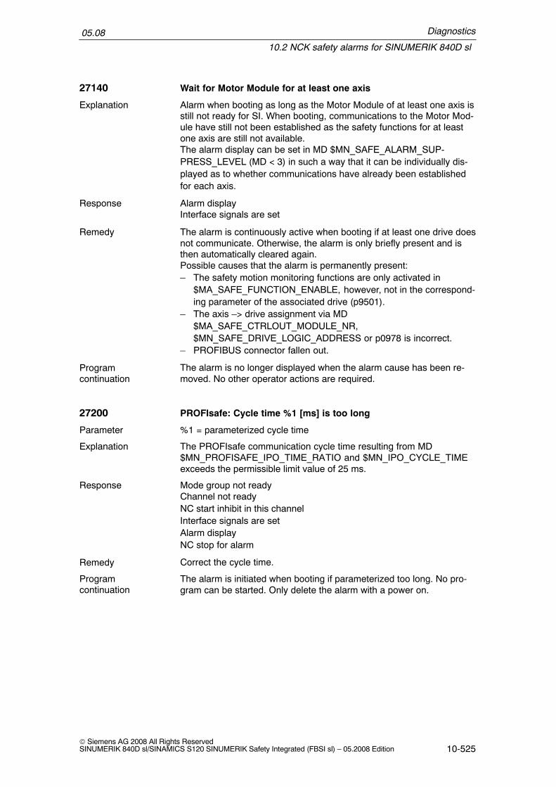
Diagnostics
10.2 NCK safety alarms for SINUMERIK 840D sl
05.08
10-525© Siemens AG 2008 All Rights ReservedSINUMERIK 840D sl/SINAMICS S120 SINUMERIK Safety Integrated (FBSI sl) – 05.2008 Edition
27140 Wait for Motor Module for at least one axis
Alarm when booting as long as the Motor Module of at least one axis isstill not ready for SI. When booting, communications to the Motor Mod-ule have still not been established as the safety functions for at leastone axis are still not available.The alarm display can be set in MD $MN_SAFE_ALARM_SUP-PRESS_LEVEL (MD < 3) in such a way that it can be individually dis-played as to whether communications have already been establishedfor each axis.
Alarm displayInterface signals are set
The alarm is continuously active when booting if at least one drive doesnot communicate. Otherwise, the alarm is only briefly present and isthen automatically cleared again.Possible causes that the alarm is permanently present:– The safety motion monitoring functions are only activated in
$MA_SAFE_FUNCTION_ENABLE, however, not in the correspond-ing parameter of the associated drive (p9501).
– The axis –> drive assignment via MD$MA_SAFE_CTRLOUT_MODULE_NR,$MN_SAFE_DRIVE_LOGIC_ADDRESS or p0978 is incorrect.
– PROFIBUS connector fallen out.
The alarm is no longer displayed when the alarm cause has been re-moved. No other operator actions are required.
27200 PROFIsafe: Cycle time %1 [ms] is too long
%1 = parameterized cycle time
The PROFIsafe communication cycle time resulting from MD$MN_PROFISAFE_IPO_TIME_RATIO and $MN_IPO_CYCLE_TIMEexceeds the permissible limit value of 25 ms.
Mode group not readyChannel not readyNC start inhibit in this channelInterface signals are setAlarm displayNC stop for alarm
Correct the cycle time.
The alarm is initiated when booting if parameterized too long. No pro-gram can be started. Only delete the alarm with a power on.
Explanation
Response
Remedy
Programcontinuation
Parameter
Explanation
Response
Remedy
Programcontinuation

Diagnostics
10.2 NCK safety alarms for SINUMERIK 840D sl
05.08
10-526© Siemens AG 2008 All Rights Reserved
SINUMERIK 840D sl/SINAMICS S120 SINUMERIK Safety Integrated (FBSI sl) – 05.2008 Edition
27201 PROFIsafe: MD %1[%2]: Bus segment %3 error
%1 = MD name%2 = MD field index%3 = parameterized bus segment
An incorrect bus segment was entered in the specified machine data.The value must be 5.
Mode group not readyChannel not readyNC start inhibit in this channelInterface signals are setAlarm displayNC stop for alarm
Correct the specified MD.
The alarm is initiated when booting. No program can be started. Onlydelete the alarm with a power on.
27202 PROFIsafe: MD %1[%2]: Address %3 error
%1 = MD name%2 = MD field index%3 = parameterized PROFIsafe address
The PROFIsafe address, parameterized in the specified MD is incorrect.
Mode group not readyChannel not readyNC start inhibit in this channelInterface signals are setAlarm displayNC stop for alarm
Correct the MD.
The alarm is initiated when booting. No program can be started. Onlydelete the alarm with a power on.
27203 PROFIsafe: MD %1[%2]: Incorrect SPL assignment
%1 = MD name%2 = MD field index
The parameterization in the specified MD for the connection betweenthe SPL interface and a PROFIsafe module is incorrect. The reasonsfor this are as follows:– Bit limits interchanged (upper bit value < lower bit value)– Bit values greater than in the definition of the SPL interface (bit
value> 64)– Number of bits too high for this PROFIsafe module (upper bit value
– lower bit value > 8)– No SPL assignment was parameterized (both bit values are equal to
zero)– Incorrect SPL assignment (bit value equal to zero)
Parameter
Explanation
Response
Remedy
Programcontinuation
Parameter
Explanation
Response
Remedy
Programcontinuation
Parameter
Explanation

Diagnostics
10.2 NCK safety alarms for SINUMERIK 840D sl
05.08
10-527© Siemens AG 2008 All Rights ReservedSINUMERIK 840D sl/SINAMICS S120 SINUMERIK Safety Integrated (FBSI sl) – 05.2008 Edition
Mode group not readyChannel not readyNC start inhibit in this channelInterface signals are setAlarm displayNC stop for alarm
Correct the displayed MD.
The alarm is initiated when booting. No program can be started. Onlydelete the alarm with a power on.
27204 PROFIsafe: Double assignment MD %1[%2] – MD %3[%4]
%1 = MD name 1%2 = MD field index for MD name 1%3 = MD name 2%4 = MD field index for MD name 2
A double assignment has been illegally parameterized in the specifiedmachine data.$A_INSE are parameterized on several PROFIsafe modules.MDs involved:– MD $MN_PROFISAFE_IN_ASSIGN
Mode group not readyChannel not readyNC start inhibit in this channelInterface signals are setAlarm displayNC stop for alarm
Correct the displayed MD.
The alarm is initiated when booting. No program can be started. Onlydelete the alarm with a power on.
27205 PROFIsafe: Number of signals in MD %1[%2] < > MD %3[%4]
%1 MD name 1%2 MD field index to the MD name 1%3 MD name 2%4 MD field index to the MD name 2
The parameterized number of signals used must be the same in bothmachine data.
Mode group not readyChannel not readyNC start inhibit in this channelInterface signals are setAlarm displayNC stop for alarm
Correct the MD.
The alarm is initiated when booting. No program can be started. Onlydelete the alarm with a power on.
Response
Remedy
Programcontinuation
Parameter
Explanation
Response
Remedy
Programcontinuation
Parameter
Explanation
Response
Remedy
Programcontinuation

Diagnostics
10.2 NCK safety alarms for SINUMERIK 840D sl
05.08
10-528© Siemens AG 2008 All Rights Reserved
SINUMERIK 840D sl/SINAMICS S120 SINUMERIK Safety Integrated (FBSI sl) – 05.2008 Edition
27206 PROFIsafe: MD %1[%2] max. number of F net data (%3 bits)exceeded
%1 MD name%2 MD field index to the MD name%3 F net data bits
Data parameterized in the specified machine data lie outside the F net(useful) data area of the F module.Note:When displaying machine data PROFISAFE_IN/OUT_ADDRESS, thesub–slot address parameterized in the machine data exceeds the F netdata area of the F module.
Mode group not readyChannel not readyNC start inhibit in this channelInterface signals are setAlarm displayNC stop for alarm
Correct the MD.
Switch control system OFF and ON again.
27207 PROFIsafe: MD %1[%2] max. sub–slot number: %3 exceeded
%1 MD name%2 MD field index to the MD name%3 max. number of sub–slots
The sub–slot parameterized in the specified machine data exceeds themax. permissible number of sub slots per PROFIsafe module.
Mode group not readyChannel not readyNC start inhibit in this channelInterface signals are setAlarm displayNC stop for alarm
Reduce the number of sub–slots by changing the F net (useful) datadistribution of the PROFIsafe module.
Switch control system OFF and ON again.
Parameter
Explanation
Response
Remedy
Programcontinuation
Parameter
Explanation
Response
Remedy
Programcontinuation

Diagnostics
10.2 NCK safety alarms for SINUMERIK 840D sl
05.08
10-529© Siemens AG 2008 All Rights ReservedSINUMERIK 840D sl/SINAMICS S120 SINUMERIK Safety Integrated (FBSI sl) – 05.2008 Edition
27208 PROFIsafe: MD %1[%2] max. sub–slot address %3 exceeded
%1 MD name%2 MD field index to the MD name%3 address, sub–slots
An excessively high sub–slot address was entered in the specified MD.The entered value may not exceed the displayed maximum sub–slotaddress.
Mode group not readyChannel not readyNC start inhibit in this channelInterface signals are setAlarm displayNC stop for alarm
Correct the MD
Switch control system OFF and ON again.
27220 PROFIsafe: Number of NCK F modules (%1) <> number of S7–Fmodules (%2)
%1 = number of parameterized NCK–F modules%2 = number of parameterized S7–F modules
The number of F modules parameterized using the NCK machine data$MN_PROFISAFE_IN/OUT_ADDRESS is:– greater than the number of PROFIBUS slaves in the configured S7
PROFIBUS– less than the number of F modules in the configured S7 PROFIBUS– greater than the number of F modules in the configured S7
PROFIBUSIf the alarm parameter %2 = 0, then none of the F modules, configuredin the S7–PROFIBUS configuration were found.Generally, the cause of this alarm is an error in the parameterization ofthe PROFIsafe master address.
Mode group not readyChannel not readyNC start inhibit in this channelInterface signals are setAlarm displayNC stop for alarm
Check the F parameterization in the MD $MN_PROFISAFE_IN/OUT_ADDRESS.Check the F configuration in the S7 PROFIBUS configuration.Check the parameterized PROFIsafe master address in MD$MN_PROFISAFE_MASTER_ADDRESS and S7 PROFIBUS configu-ration.
Switch the control OFF – ON.
Parameter
Explanation
Response
Remedy
Programcontinuation
Parameter
Explanation
Response
Remedy
Programcontinuation

Diagnostics
10.2 NCK safety alarms for SINUMERIK 840D sl
05.08
10-530© Siemens AG 2008 All Rights Reserved
SINUMERIK 840D sl/SINAMICS S120 SINUMERIK Safety Integrated (FBSI sl) – 05.2008 Edition
27221 PROFIsafe: NCK F module MD %1[%2] unknown
%1 = MD name%2 = MD field index
The F module parameterized in the specified machine data is unknownunder this PROFIsafe address in the S7 configuration.
Mode group not readyChannel not readyNC start inhibit in this channelInterface signals are setAlarm displayNC stop for alarm
Check the PROFIsafe addresses in the NCK–MD and S7–DP configu-ration
Switch control system OFF and ON again.
27222 PROFIsafe: S7 F module PROFIsafe address %1 unknown
%1 = PROFIsafe address
The F module with the specified PROFIsafe address has not beenparameterized as an F module in the NCK MD
Mode group not readyChannel not readyNC start inhibit in this channelInterface signals are setAlarm displayNC stop for alarm
Check the S7 PROFIBUS configuration. Register the module in theNCK MD
Switch control system OFF and ON again.
27223 PROFIsafe: NCK F module MD %1[%2] is not a %3 module
%1 = MD name%2 = MD field index%3 = module type
The F module parameterized in the specified NCK MD has not beendesignated as an appropriate input/output module in the S7 PROFIBUSconfiguration.– %3 = INPUT: NCK F parameterization expects an INPUT module– %3 = OUTPUT: NCK F parameterization expects an OUTPUT module– %3 = IN/OUT: NCK F parameterization expects an INPUT/OUTPUT
module
Parameter
Explanation
Response
Remedy
Programcontinuation
Parameter
Explanation
Response
Remedy
Programcontinuation
Parameter
Explanation
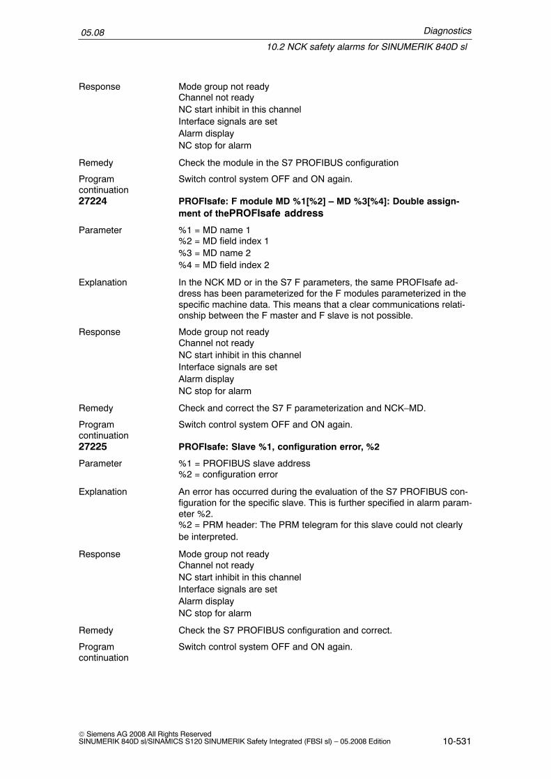
Diagnostics
10.2 NCK safety alarms for SINUMERIK 840D sl
05.08
10-531© Siemens AG 2008 All Rights ReservedSINUMERIK 840D sl/SINAMICS S120 SINUMERIK Safety Integrated (FBSI sl) – 05.2008 Edition
Mode group not readyChannel not readyNC start inhibit in this channelInterface signals are setAlarm displayNC stop for alarm
Check the module in the S7 PROFIBUS configuration
Switch control system OFF and ON again.
27224 PROFIsafe: F module MD %1[%2] – MD %3[%4]: Double assign-ment of thePROFIsafe address
%1 = MD name 1%2 = MD field index 1%3 = MD name 2%4 = MD field index 2
In the NCK MD or in the S7 F parameters, the same PROFIsafe ad-dress has been parameterized for the F modules parameterized in thespecific machine data. This means that a clear communications relati-onship between the F master and F slave is not possible.
Mode group not readyChannel not readyNC start inhibit in this channelInterface signals are setAlarm displayNC stop for alarm
Check and correct the S7 F parameterization and NCK–MD.
Switch control system OFF and ON again.
27225 PROFIsafe: Slave %1, configuration error, %2
%1 = PROFIBUS slave address%2 = configuration error
An error has occurred during the evaluation of the S7 PROFIBUS con-figuration for the specific slave. This is further specified in alarm param-eter %2.%2 = PRM header: The PRM telegram for this slave could not clearlybe interpreted.
Mode group not readyChannel not readyNC start inhibit in this channelInterface signals are setAlarm displayNC stop for alarm
Check the S7 PROFIBUS configuration and correct.
Switch control system OFF and ON again.
Response
Remedy
Programcontinuation
Parameter
Explanation
Response
Remedy
Programcontinuation
Parameter
Explanation
Response
Remedy
Programcontinuation

Diagnostics
10.2 NCK safety alarms for SINUMERIK 840D sl
05.08
10-532© Siemens AG 2008 All Rights Reserved
SINUMERIK 840D sl/SINAMICS S120 SINUMERIK Safety Integrated (FBSI sl) – 05.2008 Edition
27240 PROFIsafe: DP M has not run–up, DP info: %1
%1 = actual information from the DP interface NCK–PLC
There is no DP configuration available to the NCK after the time speci-fied using the MD $MN_PLC_RUNNINGUP_TIMEOUT.
Mode group not readyChannel not readyNC start inhibit in this channelInterface signals are setAlarm displayNC stop for alarm
Increase MD $MN_PLC_RUNNINGUP_TIMEOUTCheck the PLC operating stateCheck the PLC operating system software releaseDelete the F parameterization in the NCK–MD
Switch control system OFF and ON again.
27241 PROFIsafe: DP M version different, NCK: %1, PLC: %2
%1 = version of the DP interface on the NCK side%2 = version of the DP interface on the PLC side
The DP interface has been implemented differently for the NCK andPLC components. The F communications cannot be initialized
Mode group not readyChannel not readyNC start inhibit in this channelInterface signals are setAlarm displayNC stop for alarm
Check the PLC operating system and correct NCK software versions.Upgrade the PLC operating system.Delete NCK F parameterization.
Switch control system OFF and ON again.
Parameter
Explanation
Response
Remedy
Programcontinuation
Parameter
Explanation
Response
Remedy
Programcontinuation
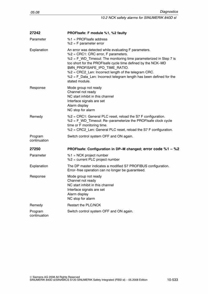
Diagnostics
10.2 NCK safety alarms for SINUMERIK 840D sl
05.08
10-533© Siemens AG 2008 All Rights ReservedSINUMERIK 840D sl/SINAMICS S120 SINUMERIK Safety Integrated (FBSI sl) – 05.2008 Edition
27242 PROFIsafe: F module %1, %2 faulty
%1 = PROFIsafe address%2 = F parameter error
An error was detected while evaluating F parameters.%2 = CRC1: CRC error, F parameters.%2 = F_WD_Timeout: The monitoring time parameterized in Step 7 istoo short for the PROFIsafe cycle time defined by the NCK–MD$MN_PROFISAFE_IPO_TIME_RATIO.%2 = CRC2_Len: Incorrect length of the telegram CRC.%2 = F_Data_Len: Incorrect telegram length has been defined for thestated module.
Mode group not readyChannel not readyNC start inhibit in this channelInterface signals are setAlarm displayNC stop for alarm
%2 = CRC1: General PLC reset, reload the S7 F configuration.%2 = F_WD_Timeout: Re–parameterize the PROFIsafe clock cycletime or F monitoring time.%2 = CRC2_Len: General PLC reset, reload the S7 F configuration.
Switch control system OFF and ON again.
27250 PROFIsafe: Configuration in DP–M changed; error code %1 – %2
%1 = NCK project number%2 = current PLC project number
The DP master indicates a modified S7 PROFIBUS configuration.Error–free operation can no longer be guaranteed.
Mode group not readyChannel not readyNC start inhibit in this channelInterface signals are setAlarm displayNC stop for alarm
Restart the PLC/NCK
Switch control system OFF and ON again.
Parameter
Explanation
Response
Remedy
Programcontinuation
Parameter
Explanation
Response
Remedy
Programcontinuation

Diagnostics
10.2 NCK safety alarms for SINUMERIK 840D sl
05.08
10-534© Siemens AG 2008 All Rights Reserved
SINUMERIK 840D sl/SINAMICS S120 SINUMERIK Safety Integrated (FBSI sl) – 05.2008 Edition
27251 PROFIsafe: F module %1, %2 reports error %3
%1 = PROFIsafe address%2 = signaling components (master/slave)%3 = error detection
An error has occurred in the PROFIsafe communications between theF master and the specified F module which was detected by the com-ponent (master/slave) displayed in parameter %2.The error code specifies the error type:– %3 = TO: The parameterized communications timeout has been
exceeded– %3 = CRC: A CRC error was detected– %3 = CN: An error was detected in the sequence (timing) of the F
telegrams– %3 = SF: F master error, NCK/PLC are no longer in synchronism– %3 = EA: Communications error, slave sends empty telegrams
Mode group not readyChannel not readyNC start inhibit in this channelInterface signals are setAlarm displayNC stop for alarm
Check the DP wiring. Restart the F slave modules. Restart the NCK/PLC.
Clear the alarm with the RESET key. Restart the part program.
27252 PROFIsafe: Slave %1, sign–of–live error
%1 = DP slave address
The specified DP slave no longer communicates with the master.
Mode group not readyChannel not readyNC start inhibit in this channelInterface signals are setAlarm displayNC stop for alarm
Check the DP wiring. Restart the F slave modules. Restart the NCK/PLC.
Clear the alarm with the RESET key. Restart the part program.
Parameter
Explanation
Response
Remedy
Programcontinuation
Parameter
Explanation
Response
Remedy
Programcontinuation

Diagnostics
10.2 NCK safety alarms for SINUMERIK 840D sl
05.08
10-535© Siemens AG 2008 All Rights ReservedSINUMERIK 840D sl/SINAMICS S120 SINUMERIK Safety Integrated (FBSI sl) – 05.2008 Edition
27253 PROFIsafe: Communications fault F master component %1, error %2
%1 = faulty components (NCK/PLC)%2 = error detection
The F master signals a communications error between the NCK andPLC.The cause of the error is indicated in error code %1:– %1 = NCK: Link between PROFIsafe and SPL interface is inter-
rupted.– %1 = PLC: The PLC no longer executes the OB40 request.– %1 = PLC–DPM: DP master is no longer in the OPERATE state.Parameter %2 provides additional information about the reason for theerror:– %2 = 0: NCK–internal sequence error (refer to %1=NCK).– %2 = 1,2,4: PLC processing of the OB40 not finished.
Mode group not readyChannel not readyNC start inhibit in this channelInterface signals are setAlarm displayNC stop for alarm
Extend the PROFIsafe cycle time using MD $MN_PROFI-SAFE_IPO_TIME_RATIO.
Clear the alarm with the RESET key. Restart the part program.
27254 PROFIsafe: F module %1, error on channel %2; %3<ALSI>
%1 = PROFIsafe address%2 = channel number%3 = supplementary info, system variables – field index
The F module signals that an error has occurred in the interface of thespecified channel. This alarm is only initiated for ET200 F modules.The type of channel (input or output channel is displayed in %2 usingthe IN and OUT abbreviation).Using parameter %3, a specific alarm message can be configured onthe HMI for each of the listed system variables:– %3 = 1....64: Error in system variables $A_INSE[1...64]– %3 = 65...128: Error in system variables $A_OUTSE[1...64]– %3 = –1: Error in the input or output channel for which there is no
SPL assignment.
Mode group not readyChannel not readyNC start inhibit in this channelInterface signals are setAlarm displayNC stop for alarm
Check the wiring. Wiring OK: Replace the F module.
Remove the error and press RESET.
Parameter
Explanation
Response
Remedy
Programcontinuation
Parameter
Explanation
Response
Remedy
Programcontinuation

Diagnostics
10.2 NCK safety alarms for SINUMERIK 840D sl
05.08
10-536© Siemens AG 2008 All Rights Reserved
SINUMERIK 840D sl/SINAMICS S120 SINUMERIK Safety Integrated (FBSI sl) – 05.2008 Edition
27255 PROFIsafe: F module %1, general error
%1 = PROFIsafe address
The specified PROFIsafe module signals an error: Additional informa-tion on the cause of the error cannot be made without further re-sources.This alarm is initiated for all types of PROFIsafe slaves.
Mode group not readyChannel not readyNC start inhibit in this channelInterface signals are setAlarm displayNC stop for alarm
Check the wiring
Remove the error and press RESET.
27256 PROFIsafe: Actual cycle time %1 [ms] > parameterized cycle time
%1 = actual PROFIsafe communications cycle time
The actual PROFIsafe communication cycle time is greater than thevalue set using MD $MN_PROFISAFE_IPO_TIME_RATIO. The para-meterized PROFIsafe communication cycle time is continually ex-ceeded on the PLC side.
Mode group not readyNC start inhibit in this channelInterface signals are setAlarm displayNC stop for alarm
Adapt the cycle time using MD $MN_PROFISAFE_IPO_TIME_RATIO.At least the value, displayed in %1 must be set.The selected cycle time has an effect on the runtime utilization of thePLC module. This must be taken into account in the setting.
Remove the error and press RESET
27299 PROFIsafe: Diagnostics %1 %2 %3 %4
%1 error ID 1%2 error ID 2%3 error ID 3%4 error ID 4
Internal error in the NCK PROFIsafe implementation.
Alarm display
Parameter
Explanation
Response
Remedy
Programcontinuation
Parameter
Explanation
Response
Remedy
Programcontinuation
Parameter
Explanation
Response

Diagnostics
10.2 NCK safety alarms for SINUMERIK 840D sl
05.08
10-537© Siemens AG 2008 All Rights ReservedSINUMERIK 840D sl/SINAMICS S120 SINUMERIK Safety Integrated (FBSI sl) – 05.2008 Edition
Please contact the Siemens I DT MC Hotline with the error text– Tel. 0180 / 5050 – 222 (Germany)– Fax 0180 / 5050 – 223– Tel. +49–180 / 5050 – 222 (outside Germany)– Fax +49–180 / 5050 – 223– mailto:[email protected]
Power–down the control and power–up again
27900 Profibus–DP: SI fault, axis %1, code %2, value %3, time %4
%1 axis number%2 fault code of the drive (p9747)%3 fault value of the drive (p9749)%4 fault time of the drive (p9748)
SINAMICS drive fault.
Alarm display
Fault codes/fault values, refer to the drive documentation.
The alarm is no longer displayed when the alarm cause has been re-moved. No other operator actions are required.
27901 Profibus–DP: SI fault, axis %1, code %2, value %3, time %4
%1 axis number%2 fault code of the drive (p9747)%3 fault value of the drive (p9749)%4 fault time of the drive (p9748)
SINAMICS drive fault.
Alarm display
Fault codes/fault values, refer to the drive documentation.
Remove the error and press RESET.
Remedy
Programcontinuation
Parameter
Explanation
Response
Remedy
Programcontinuation
Parameter
Explanation
Response
Remedy
Programcontinuation

Diagnostics
10.3 Safety messages for SINAMICS S120
05.08
10-538© Siemens AG 2008 All Rights Reserved
SINUMERIK 840D sl/SINAMICS S120 SINUMERIK Safety Integrated (FBSI sl) – 05.2008 Edition
10.3 Safety messages for SINAMICS S120
10.3.1 General information
Note
In the HMI environment, faults and alarms are displayed specifying a six–digitnumber that always starts with 2. This means, e.g. F01600 then 201600. In thisChapter, faults and alarms are described with numbers from the SINAMICSenvironment.
In the HMI environment, faults and alarms are treated like alarms.
Differences between faults and alarms
Table 10-2 Differences between faults and alarms
Type Description
Faults What happens when a fault occurs?� The appropriate fault response is initiated.� Status signal ZSW1.3 is set.� The fault is entered in the fault buffer.
How are the faults eliminated?� Remove the cause of the fault.� Acknowledge the fault.
Warnings What happens when an alarm occurs?� Status signal ZSW1.7 is set.� The warning is entered in the warning buffer.
How are alarms removed?� Alarms are self acknowledging, that is, they are reset automatically when
the cause of the alarm has been eliminated.
Fault responses
The standard fault responses according to PROFIdrive, that are used for safety,are described in the Table 10-3. The OFF 2 fault response is used as additionalstopping measure while the pulses are safely cancelled via the safety–related shut-down paths.

Diagnostics
10.3 Safety messages for SINAMICS S120
05.08
10-539© Siemens AG 2008 All Rights ReservedSINUMERIK 840D sl/SINAMICS S120 SINUMERIK Safety Integrated (FBSI sl) – 05.2008 Edition
Table 10-3 Fault responses
Faultresponse
Response Description Safety stopresponse
OFF 2
(OFF 2)
Internal/externalpulse disable
� Instantaneous pulse cancellation, the drive”coasts” to a standstill.
� The motor holding brake (if parameterized) isclosed immediately.
� Power–on disable is activated.
STOP A,
Test stop
OFF 3 Brakes along theOFF 3 downramp and thenthe pulses arecancelled
� The drive is braked along the OFF3 down ramp(p1135) by immediately entering n_set = 0.
� When zero speed is detected, the motor holdingbrake (if parameterized) is closed. The pulsesare cancelled when the brake application time(p1217) expires.
� Zero speed is detected if the actual speed dropsbelow the threshold in p1226 or if the monitoringtime (p1227) started when speed setpoint <=speed threshold (p1226) has expired.
STOP B
(after r9556has expired orp9560 is fallenbelow, STOPA is initiated)
STOP 2
(Halt 2)
n_set = 0 � The drive is braked along the OFF 3 down ramp(p1135) by immediately entering n_set = 0.
� The drive remains in closed–loop speed controlmode.
STOP C
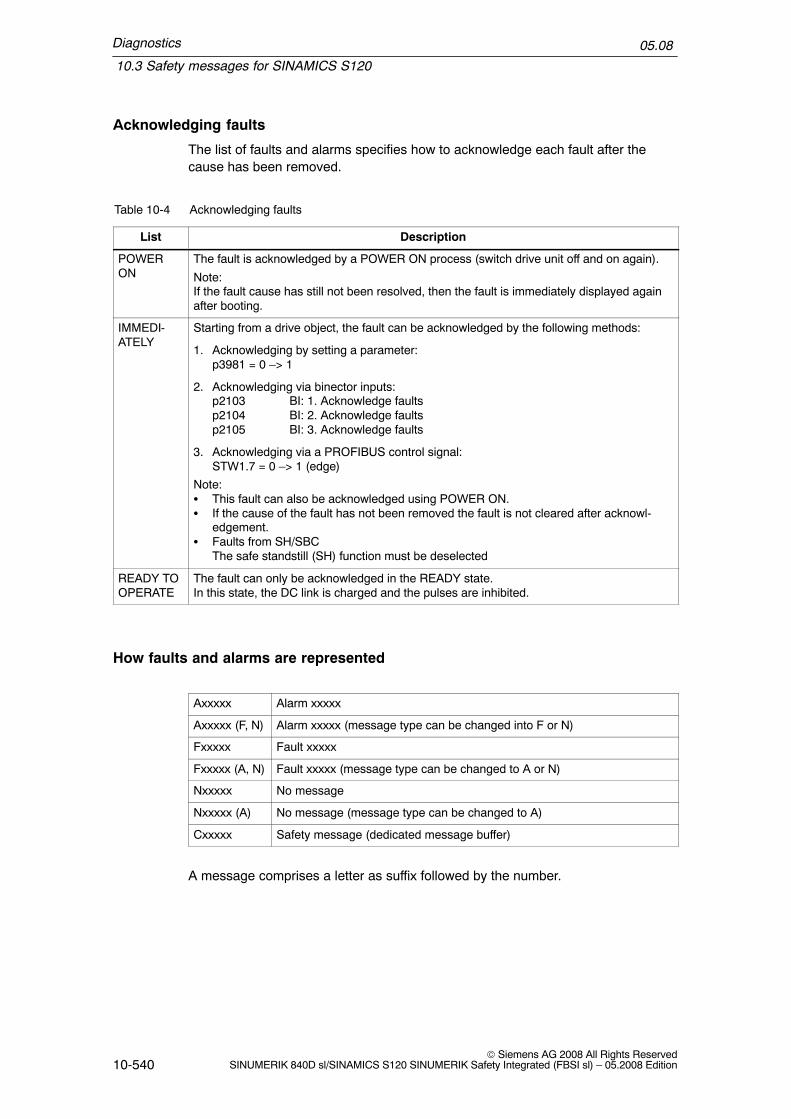
Diagnostics
10.3 Safety messages for SINAMICS S120
05.08
10-540© Siemens AG 2008 All Rights Reserved
SINUMERIK 840D sl/SINAMICS S120 SINUMERIK Safety Integrated (FBSI sl) – 05.2008 Edition
Acknowledging faults
The list of faults and alarms specifies how to acknowledge each fault after thecause has been removed.
Table 10-4 Acknowledging faults
List Description
POWERON
The fault is acknowledged by a POWER ON process (switch drive unit off and on again).
Note:If the fault cause has still not been resolved, then the fault is immediately displayed againafter booting.
IMMEDI-ATELY
Starting from a drive object, the fault can be acknowledged by the following methods:
1. Acknowledging by setting a parameter:p3981 = 0 –> 1
2. Acknowledging via binector inputs:p2103 BI: 1. Acknowledge faultsp2104 BI: 2. Acknowledge faultsp2105 BI: 3. Acknowledge faults
3. Acknowledging via a PROFIBUS control signal:STW1.7 = 0 –> 1 (edge)
Note:� This fault can also be acknowledged using POWER ON.� If the cause of the fault has not been removed the fault is not cleared after acknowl-
edgement.� Faults from SH/SBC
The safe standstill (SH) function must be deselected
READY TOOPERATE
The fault can only be acknowledged in the READY state.In this state, the DC link is charged and the pulses are inhibited.
How faults and alarms are represented
Axxxxx Alarm xxxxx
Axxxxx (F, N) Alarm xxxxx (message type can be changed into F or N)
Fxxxxx Fault xxxxx
Fxxxxx (A, N) Fault xxxxx (message type can be changed to A or N)
Nxxxxx No message
Nxxxxx (A) No message (message type can be changed to A)
Cxxxxx Safety message (dedicated message buffer)
A message comprises a letter as suffix followed by the number.

Diagnostics
10.3 Safety messages for SINAMICS S120
05.08
10-541© Siemens AG 2008 All Rights ReservedSINUMERIK 840D sl/SINAMICS S120 SINUMERIK Safety Integrated (FBSI sl) – 05.2008 Edition
The letters have the following meanings:
� A means ”Alarm”� F means ”Fault”� N means ”No message” or ”Internal message” or ”No report”� C means ”safety message”
The optional brackets indicates whether the type specified for this message can bechanged and which message types can be selected via parameter.
Information about the response and acknowledgement are independently specifiedfor a message with adjustable message type (e.g. response to F, acknowledge-ment for F).
10.3.2 List of faults and alarms
Note
� In the HMI environment, faults and alarms are displayed specifying a six–digitnumber that always starts with 2. This means, e.g. F01600 then 201600. In thisChapter, faults and alarms are described with numbers from the SINAMICSenvironment.
� In the HMI environment, faults and alarms are treated like alarms.
List of faults (Control Unit)
F01600 SI CU: STOP A initiated
OFF2
Acknowledgement IMMEDIATELY (POWER ON)
The ”Safety Integrated” function integrated in the drive on the ControlUnit has detected a fault and initiated a STOP A (pulse cancellation viathe safety shutdown path of the Control Unit).– Forced checking procedure of the safety shutdown path of the
Control Unit unsuccessful.– Subsequent response to fault F01611 (defect in a monitoring
channel).Fault value (r0949, decimal):0: Stop request from the Motor Module1005: Pulses cancelled although SH not selected and there is not internal
STOP A present.1010: Pulses enabled although SH is selected or an internal STOP A is
present.1015: Feedback of the safe pulse cancellation for Motor Modules con-
nected in parallel are different.9999: Subsequent response to fault F01611.
Response
Explanation

Diagnostics
10.3 Safety messages for SINAMICS S120
05.08
10-542© Siemens AG 2008 All Rights Reserved
SINUMERIK 840D sl/SINAMICS S120 SINUMERIK Safety Integrated (FBSI sl) – 05.2008 Edition
Select safe standstill and then deselect again.– Replace the Motor Module involved.Re fault value = 9999:– Carry out diagnostics for fault F01611 that is present.
F01611 SI CU: Defect in a monitoring channel
NONE (OFF1, OFF2, OFF3)
Acknowledgement IMMEDIATELY (POWER ON)
The ”Safety Integrated” function integrated in the drive on the ControlUnit has detected a fault in the crosswise data comparison between CUand Motor Module (MM) and has initiated a STOP F.As a result of this fault, after the parameterized transition has expired(p9658), fault F01600 (SI CU: STOP A initiated) is output.Fault value (r0949, decimal):0: Stop request from the Motor Module1 to999:
Number of the crosswise compared data that resulted in this fault.This number is also displayed in r9795.1: SI monitoring clock cycle (r9780, r9880).2: SI enable safety functions (p9601, p9801).3: SI SGE changeover, tolerance time (p9650, p9850).4: SI transition time STOP F to STOP A (p9658, p9858).5: SI enable safe brake control (p9602, p9802).6: SI motion, enable safety functions (p9501, internal value).7: SI delay time of the pulse cancellation for Safe Stop 1 (p9652,p9852).8: PROFIsafe address (p9610, p9810).
1000: Check (watchdog) timer has expired. Within the time of approx.5 * p9650 too many switching operations have occurred at terminalEP of the Motor Module.
1001,1002:
Initialization error, change timer/check timer.
2000: Status of the SH terminals on the Control Unit and Motor Module aredifferent.
2001: Feedback signal for safe pulse cancellation on the Control Unit andMotor Module are different.
2002: Status of the delay timer SS1 on the Control Unit and Motor Moduleare different.
2004: Status of the SH selection for modules connected in parallel aredifferent.
2005: Feedback signal of the safe pulse cancellation on the Control Unitand Motor Modules connected in parallel are different.
Remedy
Response
Explanation

Diagnostics
10.3 Safety messages for SINAMICS S120
05.08
10-543© Siemens AG 2008 All Rights ReservedSINUMERIK 840D sl/SINAMICS S120 SINUMERIK Safety Integrated (FBSI sl) – 05.2008 Edition
Re fault value = 1 to 999:– Check the crosswise compared data that resulted in a STOP F.– Carry out a POWER ON (power off/on) for all components.– Upgrade the Motor Module software.– Upgrade the Control Unit software.Re fault value = 1000:– Check the EP terminal at the Motor Module (contact problems).Re fault value = 1001, 1002:– Carry out a POWER ON (power off/on) for all components.– Upgrade the Motor Module software.– Upgrade the Control Unit software.Re fault value = 2000, 2001, 2002, 2004, 2005:– Check the tolerance time SGE changeover and if required, increase
the value (p9650/p9850, p9652/p9852).– Check the wiring of the safety–related inputs (SGE) (contact
problems).– Replace the Motor Module involved.
F01612 SI CU: STO inputs for power units connected in parallel different
NONE
Acknowledgement IMMEDIATELY
The drive–autonomous function ”Safety Integrated” on the Control Unit(CU) has identified different states of the AND’ed STO inputs for powerunits connected in parallel and has initiated a STOP F.As a result of this fault, after the parameterized transition has expired(p9658), fault F01600 (SI CU: STOP A initiated) is output.Fault value (r0949, interpret as binary):Binary image of the Control Unit digital inputs that are used as signalsource for the ”Safe Torque Off” function.
– Check the tolerance time SGE changeover and if required, increasethe value (p9650).Check the wiring of the safety–related inputs (SGE) (contact problems).
Remedy
Response
Explanation
Remedy

Diagnostics
10.3 Safety messages for SINAMICS S120
05.08
10-544© Siemens AG 2008 All Rights Reserved
SINUMERIK 840D sl/SINAMICS S120 SINUMERIK Safety Integrated (FBSI sl) – 05.2008 Edition
N01620 (F, A) SI CU: Safe standstill active
NONE
Acknowledgement NONE
The ”safe standstill” function has been selected on the Control Unit(CU) and is active.Note:This message does not result in a safety stop response.
None necessary.
Response as for F OFF2
Acknowledgement for F IMMEDIATELY (POWER ON)
Response for A NONE
Acknowledgement for A NONE
N01621 (F, A) SI CU: Safe Stop 1 active
NONE
Acknowledgement NONE
The ”Safe Stop 1” (SS1) function has been selected on the Control Unit(CU) and is active.Note:This message does not result in a safety stop response.
None necessary.
F01625 SI CU: Sign–of–life error in safety data
OFF2
Acknowledgement IMMEDIATELY (POWER ON)
The ”Safety Integrated” function integrated in the drive on the ControlUnit (CU) has detected an error in the sign–of–life of the safety databetween the CU and Motor Module (MM) and initiated a STOP A.– There is either a DRIVE–CLiQ communications error or communica-
tions have failed.– A time slice overflow of the safety software has occurred.Fault value (r0949, decimal):Only for internal Siemens troubleshooting.
Response
Explanation
Remedy
Response
Explanation
Remedy
Response
Explanation
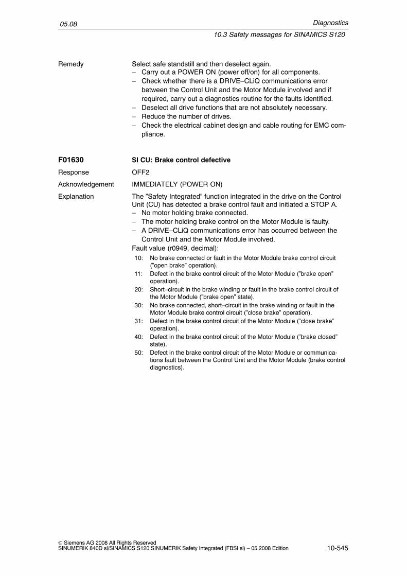
Diagnostics
10.3 Safety messages for SINAMICS S120
05.08
10-545© Siemens AG 2008 All Rights ReservedSINUMERIK 840D sl/SINAMICS S120 SINUMERIK Safety Integrated (FBSI sl) – 05.2008 Edition
Select safe standstill and then deselect again.– Carry out a POWER ON (power off/on) for all components.– Check whether there is a DRIVE–CLiQ communications error
between the Control Unit and the Motor Module involved and ifrequired, carry out a diagnostics routine for the faults identified.
– Deselect all drive functions that are not absolutely necessary.– Reduce the number of drives.– Check the electrical cabinet design and cable routing for EMC com-
pliance.
F01630 SI CU: Brake control defective
OFF2
Acknowledgement IMMEDIATELY (POWER ON)
The ”Safety Integrated” function integrated in the drive on the ControlUnit (CU) has detected a brake control fault and initiated a STOP A.– No motor holding brake connected.– The motor holding brake control on the Motor Module is faulty.– A DRIVE–CLiQ communications error has occurred between the
Control Unit and the Motor Module involved.Fault value (r0949, decimal):10: No brake connected or fault in the Motor Module brake control circuit
(”open brake” operation).11: Defect in the brake control circuit of the Motor Module (”brake open”
operation).20: Short–circuit in the brake winding or fault in the brake control circuit of
the Motor Module (”brake open” state).30: No brake connected, short–circuit in the brake winding or fault in the
Motor Module brake control circuit (”close brake” operation).31: Defect in the brake control circuit of the Motor Module (”close brake”
operation).40: Defect in the brake control circuit of the Motor Module (”brake closed”
state).50: Defect in the brake control circuit of the Motor Module or communica-
tions fault between the Control Unit and the Motor Module (brake controldiagnostics).
Remedy
Response
Explanation
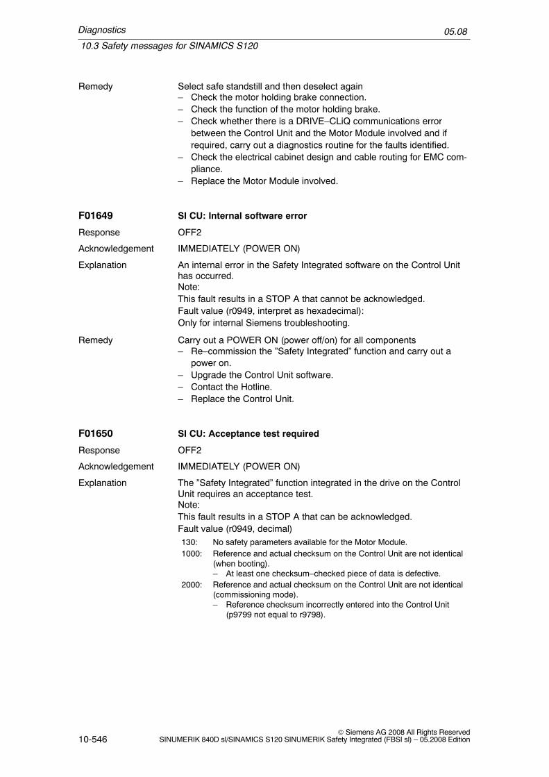
Diagnostics
10.3 Safety messages for SINAMICS S120
05.08
10-546© Siemens AG 2008 All Rights Reserved
SINUMERIK 840D sl/SINAMICS S120 SINUMERIK Safety Integrated (FBSI sl) – 05.2008 Edition
Select safe standstill and then deselect again– Check the motor holding brake connection.– Check the function of the motor holding brake.– Check whether there is a DRIVE–CLiQ communications error
between the Control Unit and the Motor Module involved and ifrequired, carry out a diagnostics routine for the faults identified.
– Check the electrical cabinet design and cable routing for EMC com-pliance.
– Replace the Motor Module involved.
F01649 SI CU: Internal software error
OFF2
Acknowledgement IMMEDIATELY (POWER ON)
An internal error in the Safety Integrated software on the Control Unithas occurred.Note:This fault results in a STOP A that cannot be acknowledged.Fault value (r0949, interpret as hexadecimal):Only for internal Siemens troubleshooting.
Carry out a POWER ON (power off/on) for all components– Re–commission the ”Safety Integrated” function and carry out a
power on.– Upgrade the Control Unit software.– Contact the Hotline.– Replace the Control Unit.
F01650 SI CU: Acceptance test required
OFF2
Acknowledgement IMMEDIATELY (POWER ON)
The ”Safety Integrated” function integrated in the drive on the ControlUnit requires an acceptance test.Note:This fault results in a STOP A that can be acknowledged.Fault value (r0949, decimal)130: No safety parameters available for the Motor Module.1000: Reference and actual checksum on the Control Unit are not identical
(when booting).– At least one checksum–checked piece of data is defective.
2000: Reference and actual checksum on the Control Unit are not identical(commissioning mode).– Reference checksum incorrectly entered into the Control Unit
(p9799 not equal to r9798).
Remedy
Response
Explanation
Remedy
Response
Explanation

Diagnostics
10.3 Safety messages for SINAMICS S120
05.08
10-547© Siemens AG 2008 All Rights ReservedSINUMERIK 840D sl/SINAMICS S120 SINUMERIK Safety Integrated (FBSI sl) – 05.2008 Edition
2001: Reference and actual checksum on the Motor Module are not identi-cal (commissioning mode).– Reference checksum incorrectly entered into the Motor Module
(p9899 not equal to r9898).2002: Enable of safety–related functions between the Control Unit and
Motor Module differ (p9601 not equal to p9801).2003: Acceptance test is required as a safety parameter has been
changed.
2004: Acceptance test required due to a project download with enabledsafety functions.
2005: The safety logbook has identified that a functional checksum haschanged. An acceptance test must be carried out.
2010: Safe brake control is enabled differently the Control Unit and MotorModule (p9602 not equal to p9802).
2020: Error when saving the safety parameters for the Motor Module.9999: Subsequent response of another safety–related fault that occurred
when booting that requires an acceptance test.
Re fault value = 130:– Carry out safety commissioning routine.Re fault value = 1000:– Repeat safety commissioning.– Replace the CompactFlash Card.Re fault value = 2000:– Check the safety parameters in the Control Unit and adapt the refer-
ence checksum (p9799).Re fault value = 2001:– Check the safety parameters on the Motor Module and adapt the
reference checksum (p9899).Re fault value = 2002:– Safety–related functions on the Control Unit and on the Motor Mod-
ule are enabled differently (p9601 not equal to p9801).Re fault value = 2003, 2004, 2005:– Carry out acceptance test and prepare acceptance report. The pro-
cedure when carrying out the acceptance test and an example forthe acceptance report are provided in the documentation for SI-NAMICS Safety Integrated. For fault value 2005 the alarm can beacknowledged if the ”Safe Torque Off” (STO) is deselected.
Re fault value = 2010:– Enable the safe brake control in the Control Unit and check on the
Motor Module (p9602 = p9802).Re fault value = 2020:– Repeat safety commissioning.– Replace the CompactFlash Card.Re fault value = 9999:– Carry out diagnostics for the other safety–related fault that is present.
Remedy

Diagnostics
10.3 Safety messages for SINAMICS S120
05.08
10-548© Siemens AG 2008 All Rights Reserved
SINUMERIK 840D sl/SINAMICS S120 SINUMERIK Safety Integrated (FBSI sl) – 05.2008 Edition
F01651 SI CU: Synchronization, safety time slices unsuccessful
OFF2
Acknowledgement IMMEDIATELY (POWER ON)
The ”Safety Integrated” function requires synchronization of the safetytime slices between the Control Unit (CU) and the Motor Module (MM)and between the Control Unit and the higher–level control. This syn-chronization routine was not successful.Note:This fault results in a STOP A that cannot be acknowledged.Fault value (r0949, decimal):Only for internal Siemens troubleshooting.
Carry out a POWER ON (power off/on) for all components– Upgrade the Motor Module software.– Upgrade the Control Unit software.– Upgrade the software of the higher–level control.
F01652 SI CU: Monitoring clock cycle not permissible
OFF2
Acknowledgement IMMEDIATELY (POWER ON)
The Safety Integrated monitoring clock cycle is not permissible:– The monitoring clock cycle integrated in the drive cannot be main-
tained due to the communication conditions requested in thesystem.
– The monitoring clock cycle for the safety–related motion monitoringfunctions with the higher–level control is not permissible (p9500).
Note:This fault results in a STOP A that cannot be acknowledged.Fault value (r0949, decimal):– When the SI monitoring, integrated in the drive is enabled
(p9601/p9801 > 0): Minimum setting for the monitoring clock cycle(in �s).
– When the motion monitoring is enabled (p9501 > 0):100: It was not possible to find an appropriate monitoring clock cycle.101: The monitoring clock cycle is not an integer multiple of the position
controller clock cycle.102: An error has occurred when transferring the DP clock cycle to the
Motor Module (MM).
103: An error has occurred when transferring the DP clock cycle to theSensor Module.
When the SI monitoring, integrated in the drive is enabled(p9601/p9801 > 0).– Upgrade the Control Unit software.When the motion monitoring is enabled (p9501 > 0):– Correct the monitoring clock cycle (p9500) and carry out a POWER ON.
Response
Explanation
Remedy
Response
Explanation
Remedy

Diagnostics
10.3 Safety messages for SINAMICS S120
05.08
10-549© Siemens AG 2008 All Rights ReservedSINUMERIK 840D sl/SINAMICS S120 SINUMERIK Safety Integrated (FBSI sl) – 05.2008 Edition
F01653 SI CU: PROFIBUS configuration error
OFF2
Acknowledgement IMMEDIATELY (POWER ON)
The PROFIBUS configuration for operating Safety Integrated monitor-ing functions with a higher–level control (SINUMERIK or F–PLC) is in-correct.Note:This fault results in a STOP A that cannot be acknowledged.Fault value (r0949, interpret as decimal):200: A safety slot has not been configured for the receive data
from the control.210,220:
The configured safety slot for the receive data from the con-trol has an unknown format.
230: The configured safety slot for the receive data from theF–PLC has the incorrect length.
240: The configured safety slot for the receive data fromSINUMERIK has the incorrect length.
300: A safety slot has not been configured for the send data to thecontrol.
310,320:
The configured safety slot for the send data to the control hasan unknown format.
330: The configured safety slot for the send data to the F–PLC hasthe incorrect length.
340: The configured safety slot for the send data to theSINUMERIK has the incorrect length.
Check the PROFIBUS configuring of the safety slot on the master sideand, if required, correct.– Upgrade the Control Unit software.
F01655 SI CU: Align the monitoring functions
OFF2
Acknowledgement IMMEDIATELY (POWER ON)
An error has occurred when aligning the Safety Integrated monitoringfunctions on the Control Unit (CU) and Motor Module (MM). ControlUnit and Motor Module were not able to determine a common set ofsupported SI monitoring functions.– DRIVE–CLiQ communications has an error or failed.– Safety Integrated software releases on the Control Unit and the
Motor Module are not compatible with one another.Note:This fault results in a STOP A that cannot be acknowledged.Fault value (r0949, interpret as hexadecimal):Only for internal Siemens troubleshooting.
Response
Explanation
Remedy
Response
Explanation

Diagnostics
10.3 Safety messages for SINAMICS S120
05.08
10-550© Siemens AG 2008 All Rights Reserved
SINUMERIK 840D sl/SINAMICS S120 SINUMERIK Safety Integrated (FBSI sl) – 05.2008 Edition
Carry out a POWER ON (power off/on) for all components– Upgrade the Motor Module software.– Upgrade the Control Unit software.– Check the electrical cabinet design and cable routing for EMC com-
pliance.
F01656 SI CU: Incorrect Motor Module parameter
OFF2
Acknowledgement IMMEDIATELY (POWER ON)
When accessing the Safety Integrated parameters for the Motor Mod-ule (MM) on the CompactFlash Card, an error has occurred.Note:This fault results in a STOP A that can be acknowledged.Fault value (r0949, decimal):129: Safety parameters for the Motor Module corrupted.131: Internal Motor Module software error.132: Communication errors when uploading or downloading the safety pa-
rameters for the Motor Module.255: Internal software error on the Control Unit.
Re–commission the safety functions.– Upgrade the Control Unit software.– Upgrade the Motor Module software.– Replace the CompactFlash Card.Re fault value = 132:– Check the electrical cabinet design and cable routing for EMC com-
pliance.
F01659 SI CU: Write task for parameter rejected
OFF2
Acknowledgement IMMEDIATELY (POWER ON)
The write task for one or several Safety Integrated parameters on theControl Unit (CU) was rejected.Note:This fault does not result in a safety stop response.Fault value (r0949, decimal):1: The Safety Integrated password is not set.2: A drive parameter reset was selected. However, the Safety Integrated
parameters cannot be reset as Safety Integrated is presently enabled.
3: The interlocked SH input is in the simulation mode.
10: An attempt was made to enable the SH function although this cannot besupported.
11: An attempt was made to enable the SBC function although this cannotbe supported.
Remedy
Response
Explanation
Remedy
Response
Explanation

Diagnostics
10.3 Safety messages for SINAMICS S120
05.08
10-551© Siemens AG 2008 All Rights ReservedSINUMERIK 840D sl/SINAMICS S120 SINUMERIK Safety Integrated (FBSI sl) – 05.2008 Edition
12: An attempt was made to enable the SBC function although this cannotbe supported for a parallel circuit configuration.
13: An attempt was made to enable the SS1 function although this cannotbe supported.
14: An attempt was made to enable the PROFIsafe communication functionalthough this cannot be supported.
15: An attempt was made to enable the motion monitoring function integra-ted in the drive although this cannot be supported.
16: An attempt was made to enable the SH function although this cannot besupported when the internal voltage protection (p1231) is enabled.
See also: p0970 (reset infeed parameters), p3900 (complete fast com-missioning), r9771 (SI common functions (Control Unit)), r9871 (SIcommon functions (Motor Module))
Re fault value = 1:– Set the Safety Integrated password (p9761).Re fault value = 2:– Inhibit Safety Integrated and again reset the drive parameters.Re fault value = 3:– Simulation mode for the digital input ended (p0795).Re fault value = 10, 11, 12, 13, 14, 15:– Check whether there are faults in the safety function alignment
between the Control Unit and the Motor Module involved (F01655,F30655) and if required, carry out diagnostics for the faults involved.
– Use a Motor Module that supports the functions ”Safe standstill”,”Safe brake control”, ”PROFIsafe”, ”Drive–integrated motion moni-toring functions”.
– Upgrade the Motor Module software.– Upgrade the Control Unit software.Re fault value = 16:– Inhibit the internal voltage protection (p1231).
See also: p9501 (SI motion enable safe functions), p9601 (SI enablefunctions integrated in the drive (Control Unit)), p9620 (SI signal sourcefor SH/SBC/SS1 (Control Unit )), p9761 (SI password input), p9801(SI enable functions integrated in the drive (Motor Module))
Remedy

Diagnostics
10.3 Safety messages for SINAMICS S120
05.08
10-552© Siemens AG 2008 All Rights Reserved
SINUMERIK 840D sl/SINAMICS S120 SINUMERIK Safety Integrated (FBSI sl) – 05.2008 Edition
F01660 SI CU: Safety–related functions not supported
OFF2
Acknowledgement IMMEDIATELY (POWER ON)
The Motor Module (MM) does not support the safety–related functions(e.g. the Motor Module version is not the correct one). Safety Integra-ted cannot be commissioned.Note:This fault results in a STOP A that cannot be acknowledged.
Use a Motor Module that supports the safety–related functions.– Upgrade the Motor Module software.
F01670 SI motion: Invalid Sensor Module parameterization
OFF2
Acknowledgement IMMEDIATELY (POWER ON)
The parameterization of a Sensor Module used for Safety Integrated isnot permissible.Note:This fault results in a STOP A that cannot be acknowledged.Fault value (r0949, decimal):1: No encoder was parameterized for Safety Integrated.2: An encoder was parameterized for Safety Integrated that does not have
an A/B (sine/cosine) track.3: The encoder data set selected for Safety Integrated is still not valid.4: The communications error with the encoder has occurred.10: For an encoder used for Safety Integrated, not all of the drive data
sets (DDS) are assigned to the same encoder data set (EDS)(p0187 ...p0189).
Re fault value = 1, 2:– Use and parameterize an encoder that Safety Integrated supports
(encoder with A/B track, sinusoidal, p0404.4 = 1)Re fault value = 3:– Check whether the device or drive commissioning is active and if
required, initiate this (p0009 = p0010 = 0), save the parameters(p0971 = 1) and carry out a power on.
Re fault value = 4:– Check whether there is a DRIVE–CLiQ communications error
between the Control Unit and the Sensor Module involved and ifrequired, carry out a diagnostics routine for the faults identified.
Re fault value = 10:– Align the EDS assignment for all encoders used for Safety Integra-
ted (p0187 ...p0189).
Response
Explanation
Remedy
Response
Explanation
Remedy

Diagnostics
10.3 Safety messages for SINAMICS S120
05.08
10-553© Siemens AG 2008 All Rights ReservedSINUMERIK 840D sl/SINAMICS S120 SINUMERIK Safety Integrated (FBSI sl) – 05.2008 Edition
F01671 SI motion: Encoder parameterization error
OFF2
Acknowledgement IMMEDIATELY (POWER ON)
The parameterization of the encoder used for Safety Integrated is notthe same as the parameterization of the standard encoder.Fault value (r0949, decimal):Parameter number of the non–corresponding safety parameter.
Align the encoder parameterization between the safety encoder and thestandard encoder.
F01672 SI motion: Motor Module software not compatible
OFF2
Acknowledgement IMMEDIATELY (POWER ON)
The existing Motor Module software does not support the safety–related motion monitoring with the higher–level control.Note:This fault results in a STOP A that cannot be acknowledged.Fault value (r0949, decimal):Only for internal Siemens troubleshooting.
Check whether there are errors in the safety function alignmentbetween the Control Unit and the Motor Module involved (F01655,F30655) and if required, carry out diagnostics for the errors involved.– Use a Motor Module that supports the safety–related motion moni-
toring functions.– Upgrade the Motor Module software.
F01673 SI motion: Sensor Module software not compatible
OFF2
Acknowledgement IMMEDIATELY (POWER ON)
The existing Sensor Module software does not support the safety–related motion monitoring with the higher–level control.Note:This fault results in a STOP A that cannot be acknowledged.Fault value (r0949, decimal):Only for internal Siemens troubleshooting.
Use a Sensor Module that supports the safety–related motion monitor-ing functions.– Upgrade the Sensor Module software.
Response
Explanation
Remedy
Response
Explanation
Remedy
Response
Explanation
Remedy

Diagnostics
10.3 Safety messages for SINAMICS S120
05.08
10-554© Siemens AG 2008 All Rights Reserved
SINUMERIK 840D sl/SINAMICS S120 SINUMERIK Safety Integrated (FBSI sl) – 05.2008 Edition
F01680 SI motion: Checksum error, safety–related monitoring functions
OFF2
Acknowledgement IMMEDIATELY (POWER ON)
The actual checksum calculated by the drive and entered into r9728over the safety–related parameters does not match the referencechecksum in p9729 saved when the machine was accepted the lasttime. The safety–related parameters have been changed or there is anerror.Note:This fault results in a STOP A that cannot be acknowledged.Fault value (r0949, decimal):0: Checksum error for SI parameters for motion monitoring1: Checksum error for SI parameters for actual values
Check the safety–related parameters and if required correct.– Carry out a POWER ON– Carry out an acceptance test.
C01681 SI motion: Incorrect parameter value
NONE
Acknowledgement IMMEDIATELY (POWER ON)
The parameter value may not be parameterized with this value.Fault value (r0949, decimal):Parameter number with the incorrect value
Correct the parameter value.
F01682 SI motion: Monitoring function is not supported
OFF2
Acknowledgement IMMEDIATELY (POWER ON)
The monitoring function enabled in p9501, p9601 or p9801is not sup-ported in this firmware version.Note:This fault results in a STOP A that cannot be acknowledged.Fault value (r0949, decimal):1: SLP monitoring function is not supported (p9501.1)2: Monitoring function SCA is not supported (pp9501.7 and p9501.8 – 15
and p9503)3: Monitoring function SLS override is not supported (p9501.5)
10: Only the servo drive object supports monitoring functions.
Response
Explanation
Remedy
Response
Explanation
Remedy
Response
Explanation

Diagnostics
10.3 Safety messages for SINAMICS S120
05.08
10-555© Siemens AG 2008 All Rights ReservedSINUMERIK 840D sl/SINAMICS S120 SINUMERIK Safety Integrated (FBSI sl) – 05.2008 Edition
20: Motion monitoring functions integrated in the drive only supported inconjunction with PROFIsafe (p9501 and p9601.1 – 2 and p9801.1 –2)
21: PROFIsafe only supported in conjunction with motion monitoring func-tions integrated in the drive (p9501 and p9601.1 – 2 and p9801.1 –2)
Deselect monitoring function involved (p9501, p9503, p9601, p9801).
F01683 SI motion: SOS/SLS enable missing
OFF2
Acknowledgement IMMEDIATELY (POWER ON)
In p9501, the safety–related basic function SOS/SLS has not been en-abled although other safety–related monitoring functions have beenenabled.Note:This fault results in a STOP A that cannot be acknowledged.
Enable the function ”SOS/SLS” (p9501.0) and carry out a POWER ON.
F01684 SI motion: Safely limited position limit values interchanged
OFF2
Acknowledgement IMMEDIATELY (POWER ON)
For the function ”Safely limited position” (SLP), in p9534 there is avalue less than that in p9535.Note:This fault results in a STOP A that cannot be acknowledged.Fault value (r0949, decimal):1: Limit values SLP1 interchanged2: Limit values SLP2 interchanged
Correct the limit values in p9534 and p9535 and carry out a POWER ON.
F01685 SI motion: Safely limited speed limit value too high
OFF2
Acknowledgement IMMEDIATELY (POWER ON)
The limit value for the function ”Safely limited speed” (SLS) is greaterthan the speed that corresponds to an encoder limit frequency of 500kHz.Fault value (r0949, decimal):Maximum permissible speed
Correct the limit values for SLS and carry out a POWER ON.
Remedy
Response
Explanation
Remedy
Response
Explanation
Remedy
Response
Explanation
Remedy

Diagnostics
10.3 Safety messages for SINAMICS S120
05.08
10-556© Siemens AG 2008 All Rights Reserved
SINUMERIK 840D sl/SINAMICS S120 SINUMERIK Safety Integrated (FBSI sl) – 05.2008 Edition
F01686 SI motion: Cam position parameterization not permissible
OFF2
Acknowledgement IMMEDIATELY (POWER ON)
Parameterization error of the safe cam positions in p9536 or p9537.The fault value indicates the number of the ”Safe cam” with the illegalposition.Causes of the fault:– The safe cam that is enabled has been parameterized too close to
the tolerance range around the modulo position.– The distance between the individual cams on a cam track is not
sufficient.– The cam length of a ”safe cam” on a cam track (= p9536[x] –
p9537[x]) is less than the required minimum length.Fault value (r0949, interpret as decimal):Number of the ”safe cam” with an illegal position.See also: p9501 (SI motion enable safety functions (Control Unit),p9503 (SI motion SCA (SN) enable (Control Unit))
Correct the cam position and carry out a POWER ON.
F01687 SI motion: Illegal parameterization of modulo value SCA (SN)
OFF2
Acknowledgement IMMEDIATELY (POWER ON)
The parameterized modulo value for the function ”safe cams” (SCA) isnot a multiple of 360 000 mDegree.
Correct the modulo value for SCA and carry out a POWER ON.
F01688 SI motion: Actual value synchronization not permissible
OFF2
Acknowledgement IMMEDIATELY (POWER ON)
It is not permissible to enable the actual value synchronization and si-multaneously a monitoring function with absolute reference (SE/SN).
Either deselect the monitoring functions with absolute reference(SE/SN) or the function ”actual value synchronization” and carry out apower on.
Response
Explanation
Remedy
Response
Explanation
Remedy
Response
Explanation
Remedy

Diagnostics
10.3 Safety messages for SINAMICS S120
05.08
10-557© Siemens AG 2008 All Rights ReservedSINUMERIK 840D sl/SINAMICS S120 SINUMERIK Safety Integrated (FBSI sl) – 05.2008 Edition
C01689 SI motion: Axis re–configured
OFF2
Acknowledgement POWER ON
The axis configuration was changed.Parameter p0108. 13 is internally set to the corrected value.Fault value (r0949, decimal):Parameter number that initiated the change.See also: p9502 (SI motion axis type)
Initiate data save on the complete Control Unit and carry out a POWER ON.
A01698 (F) SI CU: Commissioning mode active
NONE
Acknowledgement NONE
The commissioning of the ”Safety Integrated” function is selected.This message is withdrawn after the safety functions have beencommissioned.Note:This message does not result in a safety stop response.See also: p0010 (infeed commissioning, parameter filter)
None necessary
NONE (OFF1, OFF2, OFF3)
Acknowledgement for F IMMEDIATELY (POWER ON)
A01699 (F) SI CU: Shutdown paths must be tested
NONE
Acknowledgement NONE
The time set in p9659 for the forced checking procedure of the safetyshutdown paths has been exceeded. The safety shutdown paths mustbe re–tested.After the next time that the function ”safe standstill” (SH) is deselected,the message is withdrawn and the monitoring time is reset.Note:This message does not result in a safety stop response.See also: p9659 (SI forced checking procedure, timer)
Select safe standstill and then deselect again
NONE (OFF1, OFF2, OFF3)
Acknowledgement for F IMMEDIATELY (POWER ON)
Response
Explanation
Remedy
Response
Explanation
Remedy
Response
Response
Explanation
Remedy
Response

Diagnostics
10.3 Safety messages for SINAMICS S120
05.08
10-558© Siemens AG 2008 All Rights Reserved
SINUMERIK 840D sl/SINAMICS S120 SINUMERIK Safety Integrated (FBSI sl) – 05.2008 Edition
C01700 SI motion: STOP A initiated
OFF2
Acknowledgement IMMEDIATELY (POWER ON)
The drive is stopped using a STOP A (the pulses are cancelled via thesafety shutdown path of the Control Unit).Possible causes:– Stop request from the higher–level control.– Pulses have not been cancelled after a parameterized time (p9557)
after the test stop was selected.– Subsequent response of message C01706 ”SI motion: Safe
acceleration monitoring exceeded”.– Subsequent response of message C01714 ”SI motion: Safely
reduced speed exceeded”.– Subsequent response of message C01701 ”SI motion: STOP B
initiated”.
Remove the cause of the fault on the control and carry out a power on.– Check the value in p9557 – if required increase the value and carry
out a power on.– Check the shutdown path of the Control Unit (check DRIVE–CLiQ
communications).– Carry out diagnostics for message C01706.– Carry out diagnostics for message C01714.– Carry out diagnostics for message C01701.– Replace the module.– Replace the Control Unit
C01701 SI motion: STOP B activated
OFF3
Acknowledgement IMMEDIATELY (POWER ON)
The drive is stopped using STOP B (braking along the OFF3 ramp).As a result of this fault, after the time parameterized in p9556 has ex-pired or the speed threshold parameterized in p9560 has been fallenbelow, message C01700 ”STOP A initiated” is output.Possible causes– Stop request from the higher–level control.– Subsequent response of message C01714 ”SI motion: Safely
reduced speed exceeded”.– Subsequent response of message C01711 ”SI motion: Defect in a
monitoring channel”.
Remove the cause of the fault on the control and carry out a power on.– Carry out diagnostics for message C01714.– Carry out diagnostics for message C01711.
Response
Explanation
Remedy
Response
Explanation
Remedy

Diagnostics
10.3 Safety messages for SINAMICS S120
05.08
10-559© Siemens AG 2008 All Rights ReservedSINUMERIK 840D sl/SINAMICS S120 SINUMERIK Safety Integrated (FBSI sl) – 05.2008 Edition
C01706 SI motion: Safe acceleration monitoring limit exceeded.
NONE
Acknowledgement IMMEDIATELY (POWER ON)
After the initiation of STOP B or STOP C, the speed exceeded the se-lected tolerance value.The drive is stopped by the message C01700 ”STOP A initiated”.
Check the braking behavior and if required adapt the tolerance for ”safeacceleration monitoring” (SBR).
C01707 SI motion: Tolerance for safe operating stop exceeded
NONE
Acknowledgement IMMEDIATELY (POWER ON)
The actual position has moved further away from the setpoint positionthan permitted in the stop tolerance. The drive is stopped with the mes-sage C01701 ”SI motion: STOP B initiated”.
Check whether additional safety faults are present and if required, carryout the diagnostics for the faults involved.– Check whether the stop tolerance matches the accuracy and dy-
namic performance of the axis.– Carry out a power on.
C01708 SI motion: STOP C activated
STOP2
Acknowledgement IMMEDIATELY (POWER ON)
The drive is stopped using STOP C (braking along the OFF3 decelera-tion ramp). ”Safe operating stop” (SBH) is activated after the para-meterized timer has expired.Possible causes:– Stop request from the higher–level control– Subsequent response of message C01714 ”SI motion: Safely
reduced speed exceeded”.– Subsequent response of message C01715 ”SI motion: Safe limit
position exceeded”.See also: p9552 (SI motion, transition time STOP C to SBH)
Remove the cause of the fault on the control and carry out a power on.– Carry out diagnostics for message C01714.
Response
Explanation
Remedy
Response
Explanation
Remedy
Response
Explanation
Remedy

Diagnostics
10.3 Safety messages for SINAMICS S120
05.08
10-560© Siemens AG 2008 All Rights Reserved
SINUMERIK 840D sl/SINAMICS S120 SINUMERIK Safety Integrated (FBSI sl) – 05.2008 Edition
C01709 SI motion: STOP D is activated
NONE
Acknowledgement IMMEDIATELY (POWER ON)
The drive is stopped using STOP D (braking along the path). ”Safeoperating stop” (SBH) is activated after the parameterized timer hasexpired.Possible causes:– Stop request from the higher–level control– Subsequent response of message C01714 ”SI motion: Safely re-
duced speed exceeded”.– Subsequent response of message C01715 ”SI motion: Safe limit
position exceeded”.See also: p9553 (SI motion, transition time STOP D to SBH)
Remove the cause of the fault on the control and carry out a power on.– Carry out diagnostics for message C01714.
C01710 SI motion: STOP E activated
NONE
Acknowledgement IMMEDIATELY (POWER ON)
The drive is stopped using STOP E (retraction motion). ”Safe operatingstop” (SBH) is activated after the parameterized timer has expired.Possible causes:– Stop request from the higher–level control– Subsequent response of message C01714 ”SI motion: Safely
reduced speed exceeded”.– Subsequent response of message C01715 ”SI motion: Safe limit
position exceeded”.See also: p9554 (SI motion, transition time STOP E to SBH)
Remove the cause of the fault on the control and carry out a power on.– Carry out diagnostics for message C01714.
C01711 SI motion: Defect in a monitoring channel
NONE
Acknowledgement IMMEDIATELY (POWER ON)
For a crosswise comparison, the drive found a difference between inputdata or results of the monitoring functions and initiated a STOP F. Oneof the monitoring functions no longer functions reliably, i.e. safe oper-ation is no longer possible.
Response
Explanation
Remedy
Response
Explanation
Remedy
Response
Explanation

Diagnostics
10.3 Safety messages for SINAMICS S120
05.08
10-561© Siemens AG 2008 All Rights ReservedSINUMERIK 840D sl/SINAMICS S120 SINUMERIK Safety Integrated (FBSI sl) – 05.2008 Edition
If at least one monitoring function is active, then after the parameter-ized timer has expired, message C01701 ”SI motion: STOP B initiated”is output.The message value that resulted in a STOP F is displayed in r9725.Message value: (r9749, decimal):Value that resulted in the STOP F.See also: p9555 (SI motion, transition time STOP F to STOP B), r9725(SI motion diagnostics STOP F)
The message value contained in r9725 is described in message 27001of the higher–level control.
C01714 SI motion: Safely limited speed exceeded
NONE
Acknowledgement IMMEDIATELY (POWER ON)
The drive has moved faster than that specified by the speed limit value(p9531). The drive is stopped by the configured stop response (p9563).Message value: (r9749, decimal):100: SLS1 exceeded200: SLS2 exceeded300: SLS3 exceeded400: SLS4 exceeded1000: Encoder limit frequency exceeded.
Check the traversing program on the control.– Check the limits for ”Safely limited speed” (SLS) and if required
adapt (p9531).
C01715 SI motion: Safe end position exceeded
NONE
Acknowledgement IMMEDIATELY (POWER ON)
The axis has passed a parameterized end position that is monitored bythe function ”safe software limit switch” (SE).Message value: (r9749, decimal):10: SE1– fallen below11: SE1+ exceeded20: SE2– fallen below21: SE2+ exceeded
Check the traversing program on the control.– Check the limits for ”safe software limit switch” (SE) and if required
adapt (p9534, p9535).
Remedy
Response
Explanation
Remedy
Response
Explanation
Remedy

Diagnostics
10.3 Safety messages for SINAMICS S120
05.08
10-562© Siemens AG 2008 All Rights Reserved
SINUMERIK 840D sl/SINAMICS S120 SINUMERIK Safety Integrated (FBSI sl) – 05.2008 Edition
C01745 SI motion: Check the braking torque for the brake test
NONE
Acknowledgement IMMEDIATELY (POWER ON)
Parameter 2003 was used to change the normalization of the brakingtorque for the braking test. An acceptance test must be again be car-ried out for the braking test in order to define whether the braking testis still carried out with the correct braking torque.
Carry out a POWER ON/OFF.– Repeat the acceptance test for the safe brake test if the braking test
is used.
A01796 (F, N) SI motion: Wait for communication with the control
NONE
Acknowledgement NONE
The drive waits for communications to be established with the higher–level control to execute the safety motion monitoring functions.Note:In this state, the pulses are safely cancelled.
If the message is not automatically withdrawn after a longer period oftime then the following checks should be made:– Correct assignment of the axes on the higher–level control to the
drives in the drive unit.– The safety motion monitoring functions for the corresponding axis
on the higher–level control are enabled.
Response for F NONE (OFF1, OFF2, OFF3)
Acknowledgement for F IMMEDIATELY (POWER ON)
Response for N NONE
Acknowledgement for N NONE
C01797 SI motion: Axis not safely referenced
NONE
Acknowledgement IMMEDIATELY (POWER ON)
The stop position saved before powering–down does not coincide withthe actual position that is determined when powering–up.Message value: (r9749, decimal):1: Axis not referenced2: User agreement missing
If the axis cannot be automatically and safely referenced, then the usermust enter a user agreement for the new position using the appropriatesoftkey. This therefore designates this position as being a safety–re-lated position.
Response
Explanation
Remedy
Response
Explanation
Remedy
Response
Explanation
Remedy

Diagnostics
10.3 Safety messages for SINAMICS S120
05.08
10-563© Siemens AG 2008 All Rights ReservedSINUMERIK 840D sl/SINAMICS S120 SINUMERIK Safety Integrated (FBSI sl) – 05.2008 Edition
C01798 SI motion: Test stop running
NONE
Acknowledgement IMMEDIATELY (POWER ON)
The test stop is active.Message value: (r9749, decimal):
None necessary.The message is withdrawn when the test stop is completed.
C01799 SI motion: Acceptance test mode is active
NONE
Acknowledgement IMMEDIATELY (POWER ON)
The acceptance test mode is active. The POWER ON messages of thesafe motion monitoring functions can be acknowledged during the ac-ceptance test using the RESET key of the higher–level control.
None necessary.The message is withdrawn when exiting the acceptance test mode.
List of faults and alarms (Motor Module)
F30600 SI MM: STOP A initiated
OFF2
Acknowledgement IMMEDIATELY (POWER ON)
The ”Safety Integrated” function integrated in the drive on the MotorModule (MM) has detected a fault and initiated STOP A (pulse can-cellation via the safety shutdown path of the Motor Module).– Forced checking procedure of the safety shutdown path of the
Motor Module unsuccessful.– Subsequent response to fault F30611 (defect in a monitoring channel).Fault value (r0949, decimal):0: Stop request from the Control Unit1005: Pulses cancelled although SH not selected and there is not
internal STOP A present.1010: Pulses enabled although SH is selected or an internal STOP A
is present.9999: Subsequent response to fault F30611
Select safe standstill and then deselect again.– Replace the Motor Module involved.Re fault value = 9999:– Carry out diagnostics for fault F30611.
Response
Explanation
Remedy
Response
Explanation
Remedy
Response
Explanation
Remedy

Diagnostics
10.3 Safety messages for SINAMICS S120
05.08
10-564© Siemens AG 2008 All Rights Reserved
SINUMERIK 840D sl/SINAMICS S120 SINUMERIK Safety Integrated (FBSI sl) – 05.2008 Edition
F30611 SI MM: Defect in a monitoring channel
NONE (OFF1, OFF2, OFF3)
Acknowledgement IMMEDIATELY (POWER ON)
The ”Safety Integrated” function integrated in the drive on the MotorModule (MM) has detected a fault in the crosswise data comparisonbetween the Control Unit (CU) and MM and initiated a STOP F.As a result of this fault, after the parameterized transition has expired(p9858), fault F30600 (SI MM: STOP A initiated) is output.Fault value (r0949, decimal):0: Stop request from the Control Unit1 to 999:Number of the crosswise compared data that resulted in this fault.1: SI monitoring clock cycle (r9780, r9880)2: SI enable safety functions (p9601, p9801)3: SI SGE changeover, tolerance time (p9650, p9850)4: SI transition time STOP F to STOP A (p9658, p9858)5: SI enable safe brake control (p9602, p9802)6: SI motion, enable safety functions (p9501, internal value). This num-
ber is also displayed in r9895.
7: SI delay time of the pulse cancellation for Safe Stop1 on the ControlUnit and Motor Module are different.
1000: Check (watchdog) timer has expired. Within the time of approx.5 * p9850 too many switching operations have occurred at the safety–related inputs of the Control Unit.
1001,1002:
Initialization error, change timer/check timer.
2000: Status of the SH terminals on the Control Unit and Motor Module aredifferent.
2001: Feedback signal for safe pulse cancellation on the Control Unit andMotor Module are different.
2002: Status of the delay timer SS1 on the Control Unit and Motor Moduleare different.
Re fault value = 1 to 999:– Check the crosswise compared data that resulted in a STOP F.– Carry out a POWER ON (power off/on) for all components.– Upgrade the Motor Module software.– Upgrade the Control Unit software.Re fault value = 1000:– Check the wiring of the safety–related inputs (SGE) on the Control
Unit (contact problems).Re fault value = 1001, 1002:– Carry out a POWER ON (power off/on) for all components.– Upgrade the Motor Module software.– Upgrade the Control Unit software.
Response
Explanation
Remedy

Diagnostics
10.3 Safety messages for SINAMICS S120
05.08
10-565© Siemens AG 2008 All Rights ReservedSINUMERIK 840D sl/SINAMICS S120 SINUMERIK Safety Integrated (FBSI sl) – 05.2008 Edition
Re fault value = 2000, 2001, 2002:– Check the tolerance time SGE changeover and if required, increase
the value (p9650, p9850).– Check the wiring of the safety–related inputs (SGE) (contact problems).– Replace the Motor Module involved.
N30620 (F, A) SI MM: Safe torque off active
NONE
Acknowledgement NONE
The ”Safe torque off active” function was selected on the Motor Module(MM) and is active.Note:This message does not result in a safety stop response.
None necessary.
Response as for F OFF2
Acknowledgement for F IMMEDIATELY (POWER ON)
NONE
Acknowledgement for A NONE
N30621 (F, A) SI MM: Safe Stop 1 active
NONE
Acknowledgement NONE
The ”Safe Stop 1” (SS1) function has been selected on the MotorModule (MM) and is active.Note:This message does not result in a safety stop response.
None necessary.
Response as for F OFF2
Acknowledgement for F IMMEDIATELY (POWER ON)
NONE
Acknowledgement for A NONE
Response
Explanation
Remedy
Response
Response
Explanation
Remedy
Response

Diagnostics
10.3 Safety messages for SINAMICS S120
05.08
10-566© Siemens AG 2008 All Rights Reserved
SINUMERIK 840D sl/SINAMICS S120 SINUMERIK Safety Integrated (FBSI sl) – 05.2008 Edition
F30625 SI MM: Sign–of–life error in safety data
OFF2
Acknowledgement IMMEDIATELY (POWER ON)
The ”Safety Integrated” function integrated in the drive on the MotorModule (MM) has detected an error in the sign–of–life of the safetydata between the Control Unit (CU) and MM and initiated a STOP A.– There is either a DRIVE–CLiQ communications error or communica-
tions have failed.– A time slice overflow of the safety software has occurred.Fault value (r0949, decimal):Only for internal Siemens troubleshooting.
Select safe standstill and then deselect again.– Carry out a POWER ON (power off/on) for all components.– Check whether there is a DRIVE–CLiQ communications error
between the Control Unit and the Motor Module involved and ifrequired, carry out a diagnostics routine for the faults identified.
– Deselect all drive functions that are not absolutely necessary.– Reduce the number of drives.– Check the electrical cabinet design and cable routing for EMC com-
pliance.
F30630 SI MM: Brake control defective
OFF2
Acknowledgement IMMEDIATELY (POWER ON)
The ”Safety Integrated” function integrated in the drive on the MotorModule ((MM) has detected a brake control fault and initiated a STOP A.– No motor holding brake connected.– The motor holding brake control on the Motor Module or the Control
Unit is faulty.– A DRIVE–CLiQ communications error has occurred between the
Control Unit and the Motor Module.Fault value (r0949, decimal):10: No brake connected or fault in the Motor Module brake control circuit
(”open brake” operation).30: Short–circuit in the brake winding or fault in the Motor Module brake
control circuit (”close brake” operation).40: Defect in the brake control circuit of the Motor Module (”brake closed”
state).60,70:
Fault in the brake control of the Control Unit or communications faultbetween the Control Unit and Motor Module (brake control).
Response
Explanation
Remedy
Response
Explanation
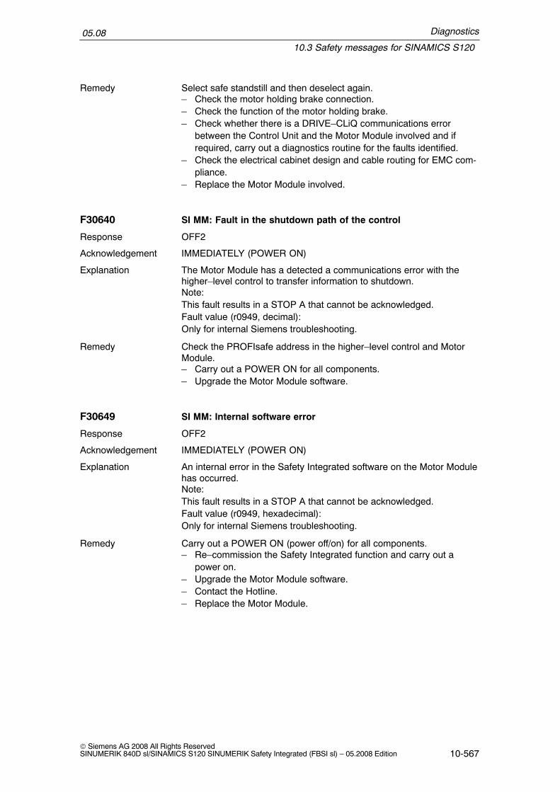
Diagnostics
10.3 Safety messages for SINAMICS S120
05.08
10-567© Siemens AG 2008 All Rights ReservedSINUMERIK 840D sl/SINAMICS S120 SINUMERIK Safety Integrated (FBSI sl) – 05.2008 Edition
Select safe standstill and then deselect again.– Check the motor holding brake connection.– Check the function of the motor holding brake.– Check whether there is a DRIVE–CLiQ communications error
between the Control Unit and the Motor Module involved and ifrequired, carry out a diagnostics routine for the faults identified.
– Check the electrical cabinet design and cable routing for EMC com-pliance.
– Replace the Motor Module involved.
F30640 SI MM: Fault in the shutdown path of the control
OFF2
Acknowledgement IMMEDIATELY (POWER ON)
The Motor Module has a detected a communications error with thehigher–level control to transfer information to shutdown.Note:This fault results in a STOP A that cannot be acknowledged.Fault value (r0949, decimal):Only for internal Siemens troubleshooting.
Check the PROFIsafe address in the higher–level control and MotorModule.– Carry out a POWER ON for all components.– Upgrade the Motor Module software.
F30649 SI MM: Internal software error
OFF2
Acknowledgement IMMEDIATELY (POWER ON)
An internal error in the Safety Integrated software on the Motor Modulehas occurred.Note:This fault results in a STOP A that cannot be acknowledged.Fault value (r0949, hexadecimal):Only for internal Siemens troubleshooting.
Carry out a POWER ON (power off/on) for all components.– Re–commission the Safety Integrated function and carry out a
power on.– Upgrade the Motor Module software.– Contact the Hotline.– Replace the Motor Module.
Remedy
Response
Explanation
Remedy
Response
Explanation
Remedy

Diagnostics
10.3 Safety messages for SINAMICS S120
05.08
10-568© Siemens AG 2008 All Rights Reserved
SINUMERIK 840D sl/SINAMICS S120 SINUMERIK Safety Integrated (FBSI sl) – 05.2008 Edition
F30650 SI MM: Acceptance test required
OFF2
Acknowledgement IMMEDIATELY (POWER ON)
The ”Safety Integrated” function on the Motor Module requires an ac-ceptance test.Note:This fault results in a STOP A that can be acknowledged.Fault value (r0949, decimal)130: No safety parameters available for the Motor Module.1000: Reference and actual checksum in the Motor Module are not identical
(boot).– At least one checksum–checked piece of data is defective.
2000: Reference and actual checksum on the Motor Module are not identi-cal (commissioning mode).– Reference checksum incorrectly entered into the Motor Module
(p9899 not equal to r9898).2003: Acceptance test is required as a safety parameter has been
changed.9999: Subsequent response of another safety–related fault that occurred
when booting that requires an acceptance test.
Re fault value = 130:– Carry out safety commissioning routine.Re fault value = 1000:– Repeat safety commissioning.– Replace the CompactFlash Card.Re fault value = 2000:– Check the safety parameters on the Motor Module and adapt the
reference checksum (p9899).Re fault value = 2003:– Carry out an acceptance test.Re fault value = 9999:– Carry out diagnostics for the other safety–related fault that is pres-
ent.See also: p9799 (SI reference checksum SI parameters (Control Unit)),p9899 (SI reference checksum, SI parameters (Motor Module)).
F30651 SI MM: Synchronization with the Control Unit unsuccessful
OFF2
Acknowledgement IMMEDIATELY (POWER ON)
The ”Safety Integrated” function integrated in the drive is requestingsynchronization of the safety time slices on the Control Unit and MotorModule. This synchronization routine was not successful.Note:This fault results in a STOP A that cannot be acknowledged.Fault value (r0949, decimal):Only for internal Siemens troubleshooting.
Response
Explanation
Remedy
Response
Explanation

Diagnostics
10.3 Safety messages for SINAMICS S120
05.08
10-569© Siemens AG 2008 All Rights ReservedSINUMERIK 840D sl/SINAMICS S120 SINUMERIK Safety Integrated (FBSI sl) – 05.2008 Edition
Carry out a POWER ON (power off/on) for all components– Upgrade the Motor Module software.– Upgrade the Control Unit software.
F30652 SSI MM: Monitoring clock cycle not permissible
OFF2
Acknowledgement IMMEDIATELY (POWER ON)
The Safety Integrated monitoring clock cycle cannot be maintained dueto the communication conditions requested in the system.Note:This fault results in a STOP A that cannot be acknowledged.Fault value (r0949, decimal):Only for internal Siemens troubleshooting.
Upgrade the Motor Module software.
F30655 SI MM: Align the monitoring functions
OFF2
Acknowledgement IMMEDIATELY (POWER ON)
An error has occurred when aligning the Safety Integrated monitoringfunctions on the Control Unit (CU) and Motor Module (MM). ControlUnit and Motor Module were not able to determine a common set ofsupported SI monitoring functions.– DRIVE–CLiQ communications has an error or failed.– Safety Integrated software releases on the Control Unit and the
Motor Module are not compatible with one another.Note:This fault results in a STOP A that cannot be acknowledged.Fault value (r0949, hexadecimal):Only for internal Siemens troubleshooting.
Carry out a POWER ON (power off/on) for all components– Upgrade the Motor Module software.– Upgrade the Control Unit software.– Check the electrical cabinet design and cable routing for EMC com-
pliance.
F30656 SI MM: Incorrect Motor Module parameter
OFF2
Acknowledgement IMMEDIATELY (POWER ON)
When accessing the Safety Integrated parameters for the Motor Mod-ule (MM) on the CompactFlash Card, an error has occurred.Note:This fault results in a STOP A that can be acknowledged.Fault value (r0949, decimal):
Remedy
Response
Explanation
Remedy
Response
Explanation
Remedy
Response
Explanation

Diagnostics
10.3 Safety messages for SINAMICS S120
05.08
10-570© Siemens AG 2008 All Rights Reserved
SINUMERIK 840D sl/SINAMICS S120 SINUMERIK Safety Integrated (FBSI sl) – 05.2008 Edition
129: Safety parameters for the Motor Module corrupted.131: Internal software error on the Control Unit.255: Internal Motor Module software error.
Re–commission the safety functions.– Upgrade the Control Unit software.– Upgrade the Motor Module software.– Replace the CompactFlash Card.
F30659 SI MM: Write task for parameter rejected
OFF2
Acknowledgement IMMEDIATELY (POWER ON)
The write task for one or several Safety Integrated parameters on theMotor Module (MM) was rejected.Note:This fault does not result in a safety stop response.Fault value (r0949, decimal):10: An attempt was made to enable the SH function although this cannot be
supported.11: An attempt was made to enable the SBC function although this cannot
be supported.13: An attempt was made to enable the SS1 function although this cannot
be supported.14: An attempt was made to enable the safe motion monitoring with the
higher–level control although this cannot be supported.
See also: r9771 (SI common functions (Control Unit)), r9871 (SI com-mon functions (Motor Module))
Re fault value = 10, 11:– Check whether there are faults in the safety function alignment
between the Control Unit and the Motor Module involved (F01655,F30655) and if required, carry out diagnostics for the faults involved.
– Use a Motor Module that supports the function safe standstill or safebrake control.
– Upgrade the Motor Module software.– Upgrade the Control Unit software.
Remedy
Response
Explanation
Remedy

Diagnostics
10.4 Safety PLC alarms
05.08
10-571© Siemens AG 2008 All Rights ReservedSINUMERIK 840D sl/SINAMICS S120 SINUMERIK Safety Integrated (FBSI sl) – 05.2008 Edition
10.4 Safety PLC alarms
400253 PLC–STOP due to an SPL system error
After an interruption in the communications between NCK and PLCregarding the SPL crosswise data comparison, the PLC was switchedinto the STOP state with a delay of 5 s.
Alarm display
Do not start the SPL anymore. Check the system components (thePLC must have the correct version of the FB 15 and have DB18).
Remove the fault. Power–down the control and power–up again
411101 FB11, illegal axis number
Parameter axis not in the permissible range
Alarm displayPLC STOP
PLC general reset, use the basic program with the correct version.
Remove the fault. Power–down the control and power–up again
Explanation
Response
Remedy
Programcontinuation
Explanation
Response
Remedy
Programcontinuation
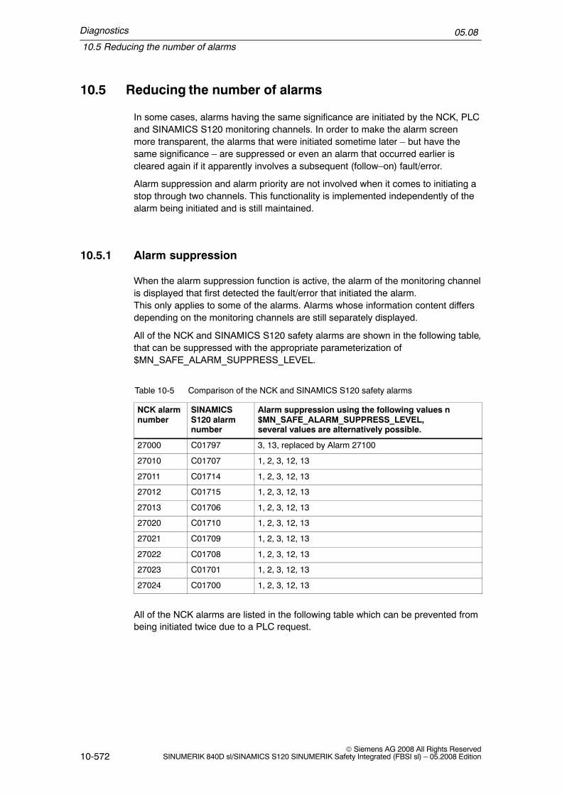
Diagnostics
10.5 Reducing the number of alarms
05.08
10-572© Siemens AG 2008 All Rights Reserved
SINUMERIK 840D sl/SINAMICS S120 SINUMERIK Safety Integrated (FBSI sl) – 05.2008 Edition
10.5 Reducing the number of alarms
In some cases, alarms having the same significance are initiated by the NCK, PLCand SINAMICS S120 monitoring channels. In order to make the alarm screenmore transparent, the alarms that were initiated sometime later – but have thesame significance – are suppressed or even an alarm that occurred earlier iscleared again if it apparently involves a subsequent (follow–on) fault/error.
Alarm suppression and alarm priority are not involved when it comes to initiating astop through two channels. This functionality is implemented independently of thealarm being initiated and is still maintained.
10.5.1 Alarm suppression
When the alarm suppression function is active, the alarm of the monitoring channelis displayed that first detected the fault/error that initiated the alarm.This only applies to some of the alarms. Alarms whose information content differsdepending on the monitoring channels are still separately displayed.
All of the NCK and SINAMICS S120 safety alarms are shown in the following table,that can be suppressed with the appropriate parameterization of$MN_SAFE_ALARM_SUPPRESS_LEVEL.
Table 10-5 Comparison of the NCK and SINAMICS S120 safety alarms
NCK alarmnumber
SINAMICSS120 alarmnumber
Alarm suppression using the following values n$MN_SAFE_ALARM_SUPPRESS_LEVEL,several values are alternatively possible.
27000 C01797 3, 13, replaced by Alarm 27100
27010 C01707 1, 2, 3, 12, 13
27011 C01714 1, 2, 3, 12, 13
27012 C01715 1, 2, 3, 12, 13
27013 C01706 1, 2, 3, 12, 13
27020 C01710 1, 2, 3, 12, 13
27021 C01709 1, 2, 3, 12, 13
27022 C01708 1, 2, 3, 12, 13
27023 C01701 1, 2, 3, 12, 13
27024 C01700 1, 2, 3, 12, 13
All of the NCK alarms are listed in the following table which can be prevented frombeing initiated twice due to a PLC request.

Diagnostics
10.5 Reducing the number of alarms
05.08
10-573© Siemens AG 2008 All Rights ReservedSINUMERIK 840D sl/SINAMICS S120 SINUMERIK Safety Integrated (FBSI sl) – 05.2008 Edition
Table 10-6 NCK alarms initiated twice
NCK alarmnumber
Alarm suppression using the following values n$MN_SAFE_ALARM_SUPPRESS_LEVEL,several values are alternatively possible.
27090 2, 3, 12, 13
27091 2, 3, 12, 13
27092 2, 3, 12, 13
27095 2, 3, 12, 13
27250 2, 3, 12, 13
27251 2, 3, 12, 13
27252 2, 3, 12, 13
27253 2, 3, 12, 13
27254 2, 3, 12, 13
27255 2, 3, 12, 13
27256 2, 3, 12, 13
Activating
The alarm is suppressed using MD 10094 $MN_SAFE_ALARM_SUPPRESS_LEVEL.When standard data is loaded, the function is already active. This means that areduced number/scope of alarms is displayed. Alarms 27000 and C01797 can bereplaced by Alarm 27100 using MD 10094.
Supplementary condition
The MD is not incorporated in the axial safety MD checksum. This means that thefunction can be enabled/disabled at any time by changing the MD. In the accep-tance test, the alarm suppression should be internally deactivated so that the two–channel fault/error detection can be checked. It can then be subsequently activatedin order to reduce the number of alarms that end users have to cope with.
10.5.2 Assigning priorities to alarms
Especially for machines with an extremely high number of axes, the previously de-scribed alarm suppression function is not adequate in order to obtain a display ofthe real fault/error codes.
Just one single destructed input signal can cause alarm 27001 (or 27101 to 27107)to occur for many axes if this input signal has been configured as SGE on severalaxes. The cause of the fault/error can be hidden as a result of the large alarm list.

Diagnostics
10.5 Reducing the number of alarms
05.08
10-574© Siemens AG 2008 All Rights Reserved
SINUMERIK 840D sl/SINAMICS S120 SINUMERIK Safety Integrated (FBSI sl) – 05.2008 Edition
This is the reason that priorities are assigned to Alarms 27090, 27004, 27001 and27101 to 27107. For these alarms
� a subsequent (follow–on) alarm that occurs afterwards is no longer displayed.This alarm is also not visible in the alarm log.
� a subsequent alarm that already occurred beforehand is cleared again. Thisalarm is then visible in the alarm log.
Assigning priorities to Alarm 27090 only becomes effective if it occurs due to differ-ences in the $A_INSE system variables. Only then will this alarm be initiated as aresult of different input signals. For Alarms 27004, 27001 and 27101 to 21107, noadditional condition is required, as
� Alarms 27001 and 27101 to 21107 cannot occur if a STOP B or a STOP A isalready present. When the SI functionality is active, STOP B and STOP A al-ways occur as subsequent error and do not provide the user with any additionalinformation about the cause of the fault or error.
� Alarm 27004 only occurs if differences are determined in the input signals.
Subsequent alarm for Alarm 27090
If Alarm 27090 is output, the following alarms are no longer displayed:
� 27001 defect in a monitoring channel� 27004 difference, safety inputs� 27020 STOP E initiated� 27021 STOP D initiated� 27022 STOP C initiated� 27023 STOP B initiated� 27024 STOP A initiated� 27091 error for crosswise data comparison, NCK–PLC� 27101 difference for the function, safe operating stop� 27102 difference for the function, safely reduced speed� 27103 difference for the function, safe end position� 27104 difference for the function, safe cam plus� 27105 difference for the function, safe cam minus� 27106 difference for the function, safely reduced speed nx� 27107 difference for the function, cam modulo monitoring
Subsequent alarm for Alarm 27004
� 27001 defect in a monitoring channel� 27023 STOP B initiated� 27024 STOP A initiated� 27101 difference for the function, safe operating stop� 27102 difference for the function, safely reduced speed� 27103 difference for the function, safe end position� 27104 difference for the function, safe cam plus� 27105 difference for the function, safe cam minus� 27106 difference for the function, safely reduced speed nx� 27107 difference for the function, cam modulo monitoring

Diagnostics
10.5 Reducing the number of alarms
05.08
10-575© Siemens AG 2008 All Rights ReservedSINUMERIK 840D sl/SINAMICS S120 SINUMERIK Safety Integrated (FBSI sl) – 05.2008 Edition
Subsequent alarms for Alarms 27001 and 27101 to 27107
� 27023 STOP B initiated� 27024 STOP A initiated
Activating
Priorities are assigned to alarms by appropriately parameterizing MD 10094$MN_SAFE_ALARM_SUPPRESS_LEVEL. When this MD is set to either 12 or 13,in addition to the alarm suppression, set with values 2 and 3, the function that as-signs priorities to alarms is also activated.
Alarm 27124
By assigning priorities to alarms, alarms with the power on clear criterion are alsocleared or no longer displayed. In spite of this, the system is in a state in which apower on is required. If alarm 27024 ”Stop A initiated” has occurred, but is no lon-ger displayed, then at least group alarm 27124 ”Stop A for at least 1 axis” is dis-played.

Diagnostics
10.5 Reducing the number of alarms
05.08
10-576© Siemens AG 2008 All Rights Reserved
SINUMERIK 840D sl/SINAMICS S120 SINUMERIK Safety Integrated (FBSI sl) – 05.2008 Edition
Space for your notes

11-577© Siemens AG 2008 All Rights ReservedSINUMERIK 840D sl/SINAMICS S120 SINUMERIK Safety Integrated (FBSI sl) – 05.2008 Edition
Interaction with Other Functions
11.1 Limiting the speed setpoint
The setpoint speed is parameterized as a function of the active safety monitoringin MD 36933: $MA_SAFE_DES_VELO_LIMIT. This machine data is not includedin the axial checksum MD 36998: $MA_SAFE_ACT_CHECKSUM, so that changescan be make to the MD for the acceptance test without having to again change thechecksum.
MD = 0%:Setpoint limiting not active
MD > 0%:Setpoint limiting = active SG limit multiplied by the MD valueFor SBH, setpoint limit = 0
MD = 100%:Setpoint limit = active SG limitFor SBH, setpoint limit = 0
� The function is effective in one channel in the NCK interpolator. The safetymonitoring channel provides a limit value that corresponds to the selectedsafety monitoring type.
� This function influences both axes and spindles.
� The active setpoint limit can be viewed in the safety service screen:Display value = –1. corresponds to ”setpoint limiting not active”Display value >= 0. corresponds to ”setpoint limiting active”
� The setpoint limit is changed–over when the SGE is changed–over:SGE ”SBH/SG deselection”SGE ”SBH deselection”SGEs ”Active SG stage, bit 0,1”SGEs ”SG override, bit 0, 1, 2, 3”Further, internal changeover operations in SBH have an effect as a result of astop response (STOP D, C, E).
11

Interaction with Other Functions
11.1 Limiting the speed setpoint
05.08
11-578© Siemens AG 2008 All Rights Reserved
SINUMERIK 840D sl/SINAMICS S120 SINUMERIK Safety Integrated (FBSI sl) – 05.2008 Edition
� For the changeover via SGEs, the states from both monitoring channels aretaken into consideration to take into account differences in the times. This re-sults in the following rules:
1. Changing–over from non–safe operation in SG/SBHThere is no delay (VELO_SWITCH_DELAY), so that this changeover mustalways be performed at zero speed or below the enabled SG limit.
2. Changing–over from SGx to SGyA) SGx > SGy (braking): A lower setpoint is entered as soon as changeoveris detected in one of the two channels.B) SGx < SGy (acceleration): A higher setpoint is only entered if both chan-nels have changed–over.
3. Changing–over from SG to SBH (braking)A lower setpoint (= 0) is entered as soon as the changeover has been de-tected in one of the two channels.
4. Changing–over from SBH to SG (accelerating)A higher setpoint is only entered if both channels have changed–over.
5. Changing–over from SBH/SG into non–safe operation (accelerating)A higher setpoint is only entered if both channels have changed–over.
� Effect of the function in the NCK interpolator:– Setpoint limiting is active in both the AUTO as well as in the JOG modes.– When changing–over while moving to higher safely reduced speeds, the
position control loop should be set so that it does not overshoot. This meansthat a sudden setpoint limit change does not cause the monitoring to re-spond on the actual value side.
– When transformation is active, safety setpoint limits, axially effective in theinterpolator are reduced by the transformation itself depending on the actualposition.
Note
There are no restrictions for motion from synchronous actions.
Interaction with Other Functions
11.2 Measuring system changeover
05.08
11-579© Siemens AG 2008 All Rights ReservedSINUMERIK 840D sl/SINAMICS S120 SINUMERIK Safety Integrated (FBSI sl) – 05.2008 Edition
11.2 Measuring system changeover
When measuring systems are changed–over (selected) via interface signals”Position measuring system 1” (DB 31..., DBX1.5)”Position measuring system 2” (DB 31..., DBX1.6) the following applies:
The encoder used by the position controller is changed–over.
Note
SI continues to work with the configured encoder.
11.3 Gantry axes
Stop responses Stop A, B, C for gantry axes are initiated as fast as possible for allof the axes in the group. However, if unacceptable offsets result because of thediffering braking behavior of the axes, then stop response Stop D should be config-ured.
11.4 Parking axis
When the park state is activated (using the interface signal ”parking”), then thesystem automatically cancels the pulses using an external STOP A. After the parkstate has been removed, the external STOP A is automatically deactivated again.
!Warning
When the ”parking” function is selected, actual value acquisition and the positionmeasuring system monitoring are deactivated for an axis/spindle. The NCK actualvalue is frozen and mechanical actual value changes are no longer detected. Thisalso applies to the actual value acquisition of the two safety monitoring channelsNCK and SINAMICS S120. This means that all of the actual value related safetymotion monitoring functions (SBH, SG, n<nx, SBR, SE, SN) are ineffective.
The user can align the actual value acquisition of the safety monitoring channelsafter re–selecting parking by again referencing/synchronizing to the machine posi-tion.

Interaction with Other Functions
11.5 OEM applications
05.08
11-580© Siemens AG 2008 All Rights Reserved
SINUMERIK 840D sl/SINAMICS S120 SINUMERIK Safety Integrated (FBSI sl) – 05.2008 Edition
Parking an axis with absolute reference (SE/SN)
As a result of the fact that the actual value sensing of the two safety monitoringchannels NCK and SINAMICS S120 has been disabled, then the absolute refer-ence of the axis is no longer detected in a safety–related fashion. The safety moni-toring channels then respond as follows:
– Alarms 27000/C01797 are displayed ”Axis no longer safely referenced”
– SGA ”Axis safely referenced” cancelled on NCK and drive side
These alarms are only displayed for axes for which safety monitoring functions withabsolute reference are activated, i.e. for SE and SN. Alarms are not displayed foraxes that do not have these monitoring functions.
Machine data SAFE_PARK_ALARM_SUPPRESS can be used to suppress Alarms27000/C01797 until parking has been withdrawn.
Note
If ”parking axis” was not requested, however ”parking active” is signaled from thedrive or encoder, then Alarm 27001 is output with fine code 1025.
11.5 OEM applications
Information for HMI–OEM users
If SINUMERIK Safety Integrated) (SI) and OEM applications (for HMI) are used atthe same time, the following points must be observed.

Interaction with Other Functions
11.6 Behavior of Safety Integrated when Profibus fails
05.08
11-581© Siemens AG 2008 All Rights ReservedSINUMERIK 840D sl/SINAMICS S120 SINUMERIK Safety Integrated (FBSI sl) – 05.2008 Edition
!Warning
1. The PLC interface signals (DB31, ...) with safety–related drive inputs andoutputs may not be written into using the variable service (utility) of theNCDDE/CAP server.
2. Write machine data using variable serviceAn acceptance test must be carried if the SI machine data were changed usingthe variable service of the NCDDE/CAP server.
3. Changing alarm prioritiesThe alarm priorities selected for SI must be retained.
4. Changing alarm testsThe alarm texts of the SI alarms can be modified: This must be clearlydocumented for the user.
5. Carry out ”acceptance test” message boxThe ”carry out acceptance test” may not be modified!
6. User acknowledgementFunctions relating to the user agreement (e.g. call, protective mechanism) maynot be altered.
Information for NCK–OEM users
SINUMERIK Safety Integrated can also be used for NCK–OEM applications.
Note
System memory changeSystem memory changes caused by the OEM application result in Alarm 27003”Checksum error occurred”.
11.6 Behavior of Safety Integrated when Profibus fails
When the drive bus fails, then communications between the drive and NCKrequired for SI also fail. The pulses are immediately cancelled from both channels.

Interaction with Other Functions
11.6 Behavior of Safety Integrated when Profibus fails
05.08
11-582© Siemens AG 2008 All Rights Reserved
SINUMERIK 840D sl/SINAMICS S120 SINUMERIK Safety Integrated (FBSI sl) – 05.2008 Edition
Space for your notes

A-583© Siemens AG 2008 All Rights ReservedSINUMERIK 840D sl/SINAMICS S120 SINUMERIK Safety Integrated (FBSI sl) – 05.2008 Edition
Appendix
A.1 Customer Support
The Centre of Competence Service (CoCS) – SINUMERIK Safety Integrated®
offers users a wide range of services.
Contact addresses
Hotline: Tel.: +49 (0)180–5050–222Fax: +49 (0)180–5050–223E–mail: mailto:[email protected] with subject 840D Safety Integrated
Contact: Tel.: +49 (0)9131 98 4386Fax: +49 (0) 9131 98 1359
Table A-1 Range of services for machine manufacturers and end customers
Portfolio Description of services
Concept development The safety functions are adapted to the machine based on the hazard analy-sis and the customer’s operating philosophy. This includes e.g.:
� Planned operating modes� Safety functions when the protective doors are closed� Safety functions when the protective doors are open� Emergency stop concept� A study of the safety–related external signals and elements
Standard engineering Based on the concept developed, the standard functions
� Safe standstill (SH), safe operating stop (SBH)� Safely reduced speed (SG)are integrated into the circuit diagram of the machine. External safety ele-ments (e.g. door interlocking, Emergency Stop button, ...) are either config-ured conventionally or logically combined using the ”safe programmablelogic” (SPL) function.
SPL configuration Based on the standard configuration, the following SPL objects are created:
� Function Block Diagram� Logic program for the PLC area� Logic program for the NC area� Data blocks required (e.g. DB 18)These objects are incorporated/linked into the complete system.
A

Appendix
A.2 References
05.08
A-584© Siemens AG 2008 All Rights Reserved
SINUMERIK 840D sl/SINAMICS S120 SINUMERIK Safety Integrated (FBSI sl) – 05.2008 Edition
Table A-1 Range of services for machine manufacturers and end customers
Portfolio Description of services
Commissioning The safety functions are commissioned based on the configuration that hasbeen created. The customer provides the machine so that the drives can betraversed and the control cabinet is wired according to the configuration.
Acceptance report Based on the submitted configuration documentation and commissioning,an acceptance report for the safety functions is drawn–up. This includes:
� Description of the machine (name, type, ...)� Description of the safety and operator concept� Description of the axis–specific safety functions� All of the safety functions are tested including the SPL logic� The test results are recordedThe customer receives the acceptance report as hard copy and on an elec-tronic data medium.
Approval procedure Support with processing and line of argument for the approval procedure bycertified bodies (e.g. regulatory bodies) or large end customers.
Workshop Workshops are held on the subject of machine safety adapted to customer–specific requirements; if required, these workshops can be held at the cus-tomer’s site. Possible contents:
� Machinery Directive, Standards in general� C Standards (machine–specific)� Hazard analysis, risk analysis� Control categories (acc. to EN 954–1)� SINUMERIK Safety Integrated® – function and system description� Configuration, machine data� Commissioning� Acceptance report
Hotline An expert for ”SINUMERIK Safety Integrated®” can be reached at the Hot-line number should series errors or problems occur during installation andcommissioning (start–up).
On–site service (local) Experts analyze problems that are encountered on–site. The causes areeliminated or counter–measures are drawn–up and implemented wherenecessary.
A.2 References
/ASI/
Low–Voltage Switchgear and SystemsCatalogSiemens Drives and Standard ProductsOrder No.: E20002–K1002–A101–A6

Appendix
A.2 References
05.08
A-585© Siemens AG 2008 All Rights ReservedSINUMERIK 840D sl/SINAMICS S120 SINUMERIK Safety Integrated (FBSI sl) – 05.2008 Edition
/1/
Directive 89/392/EEC (Machinery Directive) Bundesanzeiger Verlag.
/2/
Positionspapier des AK 226.03 im DKE: Sicherheitsgerichtete Funktionen elek-trischer Antriebssysteme in Maschinen.
/3/
Schäfer, M./Umbreit, M.: Antriebssysteme und CNC–Steuerungen mit integrierterSicherheit, BIA–Report Nr. 4/97.
/4/
Kategorien für sicherheitsbezogene Steuerungen nach EN 954–1, BIA–Report 6/97.
/5/
ZH1/419. Prüf– und Zertifizierungsordnung der Prüf– und Zertifizierungsstellen imBG–Prüfzert. (Prüf– und Zertifizierungsordnung), Ausgabe 10/97.
/6/
Reinert, D./Schäfer, M./Umbreit, M.: Antriebe und CNC–Steuerungen mit inte-grierter Sicherheit (Antriebe und CNC–Steuerungen), in: ETZ–Heft 11/98.
/7/
Johannknecht, A./Warlich, H.–J.: Maschinenschutz in Europa – BG (Maschinen–schutz).
/SHB/
Safety Integrated: The Safety System for Industry,Application Manual, 5th EditionOrder No.: 6ZB5 000–0AA01–0BA1

Appendix
A.2 References
05.08
A-586© Siemens AG 2008 All Rights Reserved
SINUMERIK 840D sl/SINAMICS S120 SINUMERIK Safety Integrated (FBSI sl) – 05.2008 Edition
Documentation
An overview of publications that is updated monthly is provided in a number of lan-guages in the Internet at:
http://www.siemens.com/motioncontrol
Follow menu items ––> ”Support” –> ”Technical Documentation” ––> ”Overview ofDocuments” or ”DOConWEB”.

Appendix
A.3 Abbreviations
05.08
A-587© Siemens AG 2008 All Rights ReservedSINUMERIK 840D sl/SINAMICS S120 SINUMERIK Safety Integrated (FBSI sl) – 05.2008 Edition
A.3 Abbreviations
1v1 1 from 1 evaluation: Encoder signal is available through onechannel, is read once
2v2 2 from 2 evaluation: Encoder signal is available through onechannel, is read twice and compared
A... Alarm
ACX Access description Compressed and eXtensible, binary formatto describe data
ASIC Application Specific Integrated Circuit (semiconductor moduledeveloped for special applications)
ASUB Asynchronous subroutine
� Susceptibility to common cause failure
BAG Mode group
BAG–STOP Stop in corresponding mode group
BG Professional association (in Germany)
BGIA German statutory industrial accident insurance institution
BiCo Binector–Connector (technology)
BO Binector Output
CCF Common Cause Failure
CDC Crosswise Data Comparison
CFG Configuration telegram
Channel_1reset
Channel reset in the 1st channel of the NCU
CO Connector Output
CPU Central Processing Unit
CRC Cyclic Redundancy Check
CU Control Unit
DAC Digital–to–Analog Converter
DB Data Block
DC Diagnostic Coverage
DDS DRIVE DATA SET (drive parameters that can be changed overtogether as a set)
DI Digital Input
DKE–AK German Electrotechnical Working Committee
DL Data Left
DMS Direct Measuring System
DP Distributed Peripherals (I/O)

Appendix
A.3 Abbreviations
05.08
A-588© Siemens AG 2008 All Rights Reserved
SINUMERIK 840D sl/SINAMICS S120 SINUMERIK Safety Integrated (FBSI sl) – 05.2008 Edition
DPM DP master
DPR Dual Port RAM
DO Digital Output
DR Data Right
DRIVE–CLiQ ”DRIVE Component Link with IQ” (official name for DSA–Linkor SA–Link: Serial bus to connect A&D drive components)
DW Data Word
EMF Electromagnetic force
EN European Standard
ENDAT Encoder Data (interface for absolute encoder)
EP Pulse enable
EQN/ERN Part of an order code for absolute/incremental encoders madeby Heidenhain
ESD ElectroStatic Discharge
ESR Extended Stop and Retract
F... Fault (F)
F–... Failsafe...
FDD Feed Drive
F–DI Failsafe input module
F–DO Failsafe output module
FOC Travel with limited torque/force (force control)
FV Failsafe Values
FXS Travel to fixed stop
GSTR Number of encoder pulses
HHU Handheld Unit
HMS High–resolution Measuring System
HW Hardware
IB Input Byte
IBN Commissioning
IEC International Electrotechnical Commission
IMP Pulse inhibit
IMS Indirect Measuring System
INSE Input data of the safe programmable logic (SPL) from the I/O
INSI Input data of the safe programmable logic (SPL) from the out-put data of the axial monitoring functions
I/O Input/Output
IPO Interpolator

Appendix
A.3 Abbreviations
05.08
A-589© Siemens AG 2008 All Rights ReservedSINUMERIK 840D sl/SINAMICS S120 SINUMERIK Safety Integrated (FBSI sl) – 05.2008 Edition
I/RF Infeed/Regenerative Feedback unit
IS Interface Signal
� Failure rate
LIFTFAST Fast retraction from contour
LL Lower Limit
LSB Least Significant Bit
MAKSIP Machine Coordinate System Actual Position
MCP Machine Control Panel
MD Machine Data or Marker Doubleword
MDD Machine Data Dialog
MDIR Machinery directive
Mixed–IO I/O module with analog and digital signals
MLFB Machine–readable product designation
MM Motor Module (power unit/power module)
MMC Man Machine Communication (operator interface for man–machine communication)
Mod. Module
MSB Most Significant Bit
MSD Main Spindle Drive
MT Machine Tool
MTTFd Mean time to dangerous failure
N... No message or internal message
NC Normally closed contact
NC Numerical Control
NCK NC Kernel
NE Line infeed
Node Id Node–Identification Code (unique ID of each DRIVE–CLiQnode)
OA Operator Acknowledge
OB Organization Block
OB Output Byte
OP Operator Panel
p... Adjustable parameters
PFHD Probability of dangerous failure per hour
PL Performance Level
PLC Programmable Logic Controller
PM–E F Power Module Electronic Failsafe

Appendix
A.3 Abbreviations
05.08
A-590© Siemens AG 2008 All Rights Reserved
SINUMERIK 840D sl/SINAMICS S120 SINUMERIK Safety Integrated (FBSI sl) – 05.2008 Edition
PNO PROFIBUS User Organization
PROFIBUS Bus system for communications between automation compo-nents
PROFIsafe Communications profile based on PROFIBUS for safety–related communications
PS Power supply
PSC PROFIsafe clock cycle
QVK Peer–to–peer data transfer
RPM Revolutions Per Minute
SA link Sensor–Actuator link
SBC Safe Brake Control
SBH Safe operating stop
SBM Safe Brake Management
SBR Safe acceleration monitoring
SBT Safe Brake Test
SCA Safe cams
SG Safely reduced speed
SGA Safety–related output
SGE Safety–related input
SH Safe standstill
SI SINUMERIK Safety Integrated® (integrated safety technology)
SIL Safety Integrity Level
SILCL SIL claim limit
SK Softkey
SLP Safely Limited Position
SLS Safely Limited Speed
SMC Sensor Module Cabinet Mounted: External adapter box to con-nect an encoder to DRIVE–CLiQ
SME Sensor Module Externally Mounted: Sensor Module with a highdegree of protection for mounting outside the electrical/controlcabinet
SMI Sensor Module Integrated: External adapter box to connect anencoder to DRIVE–CLiQ, integrated in the motor
SMM Safe Motion Monitoring
SN Safe cam, safe cam track
SOS Safe Operating Stop
SPL Safe Programmable Logic
SS1 Safe Stop 1 (corresponds to Stop Category 1 acc. to EN 60204)

Appendix
A.3 Abbreviations
05.08
A-591© Siemens AG 2008 All Rights ReservedSINUMERIK 840D sl/SINAMICS S120 SINUMERIK Safety Integrated (FBSI sl) -- 05.2008 Edition
SS1 Safe Stop 1
SS2 Safe Stop 2
SSFK Leadscrew Error Compensation
SSM Safe Speed Monitor
STO Safe Torque Off
STOP A, B, C,D, E, F
Stop response: In the event of a fault, the system respondscorresponding to the configured stop response
SW Software
T1 Lifetime
T2 Diagnostic test interval
TCP Tool Center Point
TEA Testing Data Active
Ü Gear Ratio
UI User Interface
UL Upper Limit

Appendix
A.4 Terms
05.08
A-592© Siemens AG 2008 All Rights Reserved
SINUMERIK 840D sl/SINAMICS S120 SINUMERIK Safety Integrated (FBSI sl) – 05.2008 Edition
A.4 Terms
Category
Used in EN 954–1 to ”Classify safety–related parts of control with reference to theirimmunity to faults and their behavior when a fault condition exists as a result of thestructural arrangement of the parts/components and/or their reliability”.
Channel
Element or group of elements that execute function(s) independently of oneanother.
2–channel structureThis is a structure that is used to achieve fault tolerance.For instance, a 2–channel protective door control can only be implemented if atleast two enable circuits are available and the main circuit is redundantly shutdown or a sensor (e.g. Emergency Stop switch) with two contacts is interrogatedand these are separately routed to the evaluation unit.
Fail–safe
The ability of a control system, also when faults occur (failure), to maintain a safecondition of the controlled equipment (e.g. machine, process), or to bring theequipment into a safe condition.
Failure/Fault
FailureA piece of equipment or device can no longer execute the demanded function.
FaultUndesirable condition of a piece of equipment or a device, characterized by thefact that it is unable to execute the demanded function.
Note: ”Failure” is an event and ”fault” is a condition.
Fault tolerance
Fault tolerance N means that a piece of equipment can still execute the requiredtask even if N faults are present. For N+1 faults, the equipment can no longer exe-cute the required function.
Final controlling element
Converter that converts electrical signals into mechanical or other non–electricalquantities.
Performance Level (PL)
The revision of ISO 13849–1 (with EN designation EN 954–1) includes guidelinesto simply develop, test and certify safety–related machine controls. Deterministicand probability requirements are combined with one another in a practical fashion.The control category (defined e.g. using redundancy and testing) and probabilityaspects (failure rate of the components and quality of the tests, expressed in theform of MTTFd and DC, as well as common cause faults) are used as basis todefine the so–called ”Performance Levels” (PL). Markov models, based on typical

Appendix
A.4 Terms
05.08
A-593© Siemens AG 2008 All Rights ReservedSINUMERIK 840D sl/SINAMICS S120 SINUMERIK Safety Integrated (FBSI sl) – 05.2008 Edition
control architectures, were used to derive the average, hazardous probability offailure per hour.
Redundancy
Availability of more than the necessary equipment to execute the required tasks.
Risk
Combination of the probability of damage occurring and the extent of the damage.
Safety
Free from any unacceptable risk.
Functional safetyThe part of the safety of a piece of equipment (e.g. machine, plant) that dependson the correct function.
Safety function
Function, (e.g. of a machine or a control) whose failure can increase the risk/risks.
Safety functions of controls (EN 954)
A function ”initiated by an input signal and processed by the safety–related parts ofcontrols, that allows the machine (as system) to reach a safe condition”.
Safety goal
To keep the potential hazards for personnel and the environment as low as pos-sible without restricting more than absolutely necessary, industrial production, theuse of machines or the manufacture of chemical products.
Safety Integrity Level (SIL)
Measure, defined in IEC 61508, for the safety–related performance of an electricalor electronic control device.
Stop Category
Term used in EN 60204–1 to designate three different stopping functions.
Stopping
Function that is intended to avoid or reduce impending or existing hazards for per-sonnel, damage to the machine or the execution of work. This has priority over alloperating modes.

Appendix
A.4 Terms
05.08
A-594© Siemens AG 2008 All Rights Reserved
SINUMERIK 840D sl/SINAMICS S120 SINUMERIK Safety Integrated (FBSI sl) – 05.2008 Edition
Space for your notes

I-595© Siemens AG 2008 All Rights ReservedSINUMERIK 840D sl/SINAMICS S120 SINUMERIK Safety Integrated (FBSI sl) – 05.2008 Edition
IndexSymbols$A_STOPESI, 6-138$MN_INFO_PROFISAFE_CYCLE_TIME,
7-210$VA_STOPSI, 6-138
Numbers3–terminal concept, 7-190
AAbsolute encoders, 5-96Acceptance report, 4-80Acceptance test, 4-79, 9-408Actual value synchronization, 5-107Adjusting the motor encoder, 5-99Alarms, for 840D, 10-457Assigning priorities to alarms, 10-573Axis not referenced, 5-100Axis referenced (homed), 5-101Axis safely referenced, 5-101
BBasic Standards, 1-20Brake test, 7-250
CCalibrating the machine, 5-100Cam range bit, 8-367Cam signals, 6-167Cam track, 6-172Category, A-592Changing SI data, 9-410Changing–over the speed limit values, 6-151Channel, A-592Clock cycle overruns, 7-210CNC controls, 2-35Commissioning 840D sl
First commissioning, 9-403Series commissioning, 9-409
Communication, NCK and PLC–SPL, 7-249Comparison clock cycle, for 840D, 8-267Control gears, 5-105Correction factor, safely reduced speed, 8-362Crosswise data comparison, 4-54, 5-93, 7-224
DD/A converter output, 9-413Dark period, 4-65Data, changing, 9-410Defining the cam positions, 6-169Delete password, 9-408Different channel run times, 7-187Diverse structure, 2-38, 2-40Downloading standard motor data, 8-317
EElectrical safety, 1-27EMC Directive, 1-18EN 61508, 1-25Enable, functions, 8-276Enable option, for 840D, 9-403Enabling functions, 5-109Encoder limit frequency, 6-149Encoder limit frequency, parameterizable,
6-149Encoder type combinations, 5-96Encoder types, 5-96
2–encoder system, 5-98ESR, 6-137
FF master, 7-211F net data filter, 7-212, 7-215Fail–safe, A-592Failure/Fault, A-592Fault tolerance, A-592Final controlling element, A-592Forced checking procedure, 4-58, 7-188
Safety relay, 7-241
GGantry axis, 11-579Group Standards, 1-20
IIncremental encoder, 5-96Initialization, Safety relay, 7-238
Index 05.08
I-596© Siemens AG 2008 All Rights Reserved
SINUMERIK 840D sl/SINAMICS S120 SINUMERIK Safety Integrated (FBSI sl) – 05.2008 Edition
Interface signalsfrom the drive, 8-366to the drive, 8-361
LLimiting frequency, 6-149Limiting the speed setpoint, 11-577Logbook, 9-408
MMachine data for 840D
Description, 8-266Overview, 8-261
Measuring system changeover, 11-579Modulo display, 6-171Modulo value, safe cams, 8-278Monitoring channel, 7-181Monitoring cycle, 5-91
for 840D, 8-266Motor encoder, 5-96Multiple assignment, 7-196Multiple distribution, 7-195
NNCK–SPL programming, 7-228NCK–SPL SGEs/SGAs, 7-185
OOEM applications, 11-580
PParking an axis, 11-579Parking an axis with absolute reference,
11-579Password for Safety Integrated, 4-57Password Set, 9-403PDS, 3-47Power Drive Systems, 3-47Powering–up, 5-112Probability of failure, 3-46Product Standards, 1-20PROFIBUS–DP, 7-198PROFIsafe clock cycle overruns, 7-210PROG_EVENT mechanism, 7-231PROG_EVENT.SPF, 7-231
Protective mechanisms, 7-228
RRedundancy, A-593Reference point reached, 5-100, 5-101Replacing a motor, 9-427Replacing an encoder, 9-427Risk, A-593Risk analysis, 1-26Risk assessment, 1-27Rotary axis, 8-276
Cam actual value range, 6-171Endlessly turning, 6-171Modulo display, 6-171Safe software cams, 6-171
SSafe Brake Management, 7-250Safe acceleration monitoring, 6-144Safe cam track, 6-168, 6-172Safe cams, 6-167Safe limit switches, 6-163Safe operating stop, 6-118
Deselection, 6-121Features, 6-118Prerequisites, 6-119Selection, 6-119
Safe software camsFeatures, 6-167Prerequisites, 6-169Special case, 6-169Tolerance, 6-167Hysteresis, 6-170
Safe software limit switchesConfigurable stop responses, 6-164Features, 6-163Limit values, 6-163Prerequisites, 6-164
Safe standstillFeatures, 6-114Selecting/deselecting, 6-114
Safe Stop 1, 4-61Safely reduced speed, 6-148
Changing–over the limit values, 6-151Override for, 6-156, 8-362

Index05.08
I-597© Siemens AG 2008 All Rights ReservedSINUMERIK 840D sl/SINAMICS S120 SINUMERIK Safety Integrated (FBSI sl) – 05.2008 Edition
Safely reduced speed (safely limited speed)Configured stop responses, 6-153Features, 6-148Prerequisites, 6-148Selection, 6-150
Safety, A-593Safety function, A-593Safety goal, A-593Safety Integrated
Acknowledging faults, 4-76Function diagram overview, 4-78Parameter overview, 4-77Password, 4-57Stop responses, 4-74
Safety Integrity Level (SIL), A-593Safety relay, 7-236Safety relay, test, 7-241Save machine data, with 840D sl, 9-392Save stop position, 5-102Saved stop position, 5-102SBH, 6-118SBR, 6-144SBT, 7-250SE, 6-163Selecting speed limit values, 6-150Series startup, 9-409Service display, 7-183Service displays for 840D sl, 10-436Servo trace, 9-413, 10-446Servo trace signals, 10-454Set axis monitor, 9-407Setpoint speed, 11-577SG, 6-148SG override, 6-156, 8-362SG specific STOPs, 6-155SGA, SBH active, 6-122SGE/SGA
Signal propagation delays, 7-187How many are required as a minimum?,
7-186SGEs, Standstill via STOP, 6-129Shutdown paths
Stop responses, 6-125Test, 6-117
SI relay, 7-236SIRELAY, 7-240Slip for 2–encoder system, 5-107SN, 6-168Softkey
Acknowledge SI data, 9-392Copy SI data, 9-391
Speed/standstill monitoring, 2-35SPL data on the PLC side, 7-247
SPL start without axial safety enable, 7-231SPL system errors, 7-225SPL–SGA, PROFIsafe, 7-216SPL–SGE, PROFIsafe, 7-213SS1, 4-61Standstill via SGEs, 6-129Start SPL, 7-234STO, 4-59STOP A, Description, 6-132STOP C, Description, 6-135Stop Category, A-593STOP D, Description, 6-136STOP E, Description, 6-137STOP F, Description, 6-139Stop response
SG specific, 6-155STOP A, 4-75STOP F, 4-75
Stop responsesAssignment table, 6-128Priority, 6-128Procedure, 6-129
Stop responses, configurable, 6-127Stopping, A-593Sub–slot, 7-211, 7-214Synchronized action, 7-227Synchronizing cam signals, Enable, 6-169System variable, 7-244System variable $VA_IS, 8-381System variables $A_XFAULTSI,
$VA_XFAULTSI, 8-382
TTest stop
Time, 6-117for external STOPs, 6-142
Testing the shutdown paths, 4-58Tolerance for SN, 6-167Troubleshooting, with 840D sl, 10-435Two–channel structure, 2-38, 2-40Two–encoder system, 5-98
UUser acknowledgement, 5-103, 9-408User agreement: Interlock, 5-105
VVelocities and speeds, 6-149

Index 05.08
I-598© Siemens AG 2008 All Rights Reserved
SINUMERIK 840D sl/SINAMICS S120 SINUMERIK Safety Integrated (FBSI sl) – 05.2008 Edition
ZZero speed tolerance, 6-118

From
Name
Address of your Company/Dept.
Address
Postal code City:
Phone: /
Suggestions
Corrections
For Publication/Manual:
SINUMERIK 840D sl/SINAMICS S120SINUMERIK Safety Integrated(FBSI sl)
Order No. 6FC5397–4BP10–2BA0
Edition: 05/2008
Should you come across anyprinting errors when reading thispublication, please notify us on thissheet.Suggestions for improvement arealso welcome.
To SIEMENS AGI DT MC MS1Postfach 3180
D–91050 ErlangenFax: +49 (0) 9131 / 98 – 63315 [Documentation]mailto:[email protected]://www.siemens.com/automation/service&support
Fax: /
Suggestions and/or corrections
