siprotec 5 v7.00 and higher overcurrent … 5 v7.00 and higher overcurrent protection 7sj82/7sj85...
TRANSCRIPT

SIPROTEC 5 V7.00 and higherOvercurrent Protection 7SJ82/7SJ85
Technical Data
Extract from manual C53000-G5040-C017-6, chapter 11
Energy Automation

iiNOTE
For your own safety, observe the warnings and safety instructions contained in this document, if available.
Disclaimer of LiabilityThis document has been subjected to rigorous technicalreview before being published. It is revised at regular inter-vals, and any modifications and amendments are includedin the subsequent issues. The content of this documenthas been compiled for information purposes only. AlthoughSiemens AG has made best efforts to keep the documentas precise and up-to-date as possible, Siemens AG shallnot assume any liability for defects and damage whichresult through use of the information contained herein.This content does not form part of a contract or of businessrelations; nor does it change these. All obligations ofSiemens AG are stated in the relevant contractual agree-ments.Siemens AG reserves the right to revise this documentfrom time to time.Document version: C53000-G5040-C017-6.01Edition: 11.2015Version of the product described: V7.00 and higher
CopyrightCopyright © Siemens AG 2015. All rights reserved.The disclosure, duplication, distribution and editing of thisdocument, or utilization and communication of the contentare not permitted, unless authorized in writing. All rights,including rights created by patent grant or registration of autility model or a design, are reserved.Registered TrademarksSIPROTEC®, DIGSI®, SIGUARD®, SIMEAS®, and SICAM®
are registered trademarks of Siemens AG. Any unauthor-ized use is illegal. All other designations in this documentcan be trademarks whose use by third parties for their ownpurposes can infringe the rights of the owner.

Preface
Purpose of the ManualDocument
This manual describes the protection, automation, control, and supervision functions of the SIPROTEC 5device functions for distance protection and line differential protection.This document describes a single protection, automation, control, or supervision function of the SIPROTEC 5device functions. The document shall thus be considered as part of the main device manual.
Target Audience
Protection system engineers, commissioning engineers, persons entrusted with the setting, testing and main-tenance of automation, selective protection and control equipment, and operational crew in electrical installa-tions and power plants.
Scope
This manual applies to the SIPROTEC 5 device family.
Further Documentation
[dwprefdm-221012-01.tif, 3, en_US]
• Device manualsEach Device manual describes the functions and applications of a specific SIPROTEC 5 device. Theprinted manual and the online help for the device have the same informational structure.
• Hardware manualThe Hardware manual describes the hardware building blocks and device combinations of theSIPROTEC 5 device family.
SIPROTEC 5, Overcurrent Protection, Manual 3C53000-G5040-C017-6, Edition 11.2015

• Operating manualThe Operating manual describes the basic principles and procedures for operating and assembling thedevices of the SIPROTEC 5 range.
• Communication protocol manualThe Communication protocol manual contains a description of the protocols for communication withinthe SIPROTEC 5 device family and to higher-level network control centers.
• Product informationThe Product information includes general information about device installation, technical data, limitingvalues for input and output modules, and conditions when preparing for operation. This document isprovided with each SIPROTEC 5 device.
• Engineering GuideThe Engineering Guide describes the essential steps when engineering with DIGSI 5. In addition, theEngineering Guide shows you how to load a planned configuration to a SIPROTEC 5 device and updatethe functionality of the SIPROTEC 5 device.
• DIGSI 5 online helpThe DIGSI 5 online help contains a help package for DIGSI 5 and CFC.The help package for DIGSI 5 includes a description of the basic operation of software, the DIGSI princi-ples and editors. The help package for CFC includes an introduction to CFC programming, basic exam-ples of working with CFC, and a reference chapter with all the CFC blocks available for the SIPROTEC 5range.
• SIPROTEC 5/DIGSI 5 TutorialThe tutorial on the DVD contains brief information about important product features, more detailed infor-mation about the individual technical areas, as well as operating sequences with tasks based on prac-tical operation and a brief explanation.
• SIPROTEC 5 catalogThe SIPROTEC 5 catalog describes the system features and the devices of SIPROTEC 5.
• Selection guide for SIPROTEC and ReyrolleThe selection guide offers an overview of the device series of the Siemens protection devices, and adevice selection table.
Indication of Conformity
This product complies with the directive of the Council of the European Communi-ties on harmonization of the laws of the Member States relating to electromagneticcompatibility (EMC Council Directive 2004/108/EC – valid until April, 19th of 2016,EMC Council Directive 2014/30/EU – valid from April, 20th of 2016) and concerningelectrical equipment for use within specified voltage limits (Low Voltage Directive2006/95/EG – valid until April, 19th of 2016, Low Voltage Directive 2014/35/EU –valid from April, 20th of 2016).This conformity has been proved by tests performed according to the Council Direc-tive in accordance with the product standard EN 60255-26 (for EMC directive) andwith the product standard EN 60255-27 (for Low Voltage Directive) by Siemens AG.The device is designed and manufactured for application in an industrial environ-ment.The product conforms with the international standards of IEC 60255 and theGerman standard VDE 0435.
Other Standards
IEEE Std C 37.90The technical data of the product is approved in accordance with UL.For more information about the UL database, see www.ul.comSelect Online Certifications Directory and enter E194016 as UL File Number.
Preface
4 SIPROTEC 5, Overcurrent Protection, ManualC53000-G5040-C017-6, Edition 11.2015

IND. CONT. EQ.69CA
[ul_listed_c_us, 1, --_--]
Additional Support
For questions about the system, please contact your Siemens sales partner.
Support
Our Customer Support Center provides a 24-hour service.
Phone: +49 (180) 524-7000Fax: +49 (180) 524-2471E-Mail: [email protected]
Training Courses
Inquiries regarding individual training courses should be addressed to our Training Center:
Siemens AGSiemens Power Academy TD Humboldtstraße 5990459 NürnbergGermany Phone: +49 (911) 433-7415Fax: +49 (911) 433-7929E-Mail: [email protected]: www.siemens.com/poweracademy
Notes on Safety
This document is not a complete index of all safety measures required for operation of the equipment(module or device). However, it comprises important information that must be followed for personal safety, aswell as to avoid material damage. Information is highlighted and illustrated as follows according to the degreeof danger:
! DANGERDANGER means that death or severe injury will result if the measures specified are not taken.
² Comply with all instructions, in order to avoid death or severe injuries.
! WARNINGWARNING means that death or severe injury may result if the measures specified are not taken.
² Comply with all instructions, in order to avoid death or severe injuries.
Preface
SIPROTEC 5, Overcurrent Protection, Manual 5C53000-G5040-C017-6, Edition 11.2015
! CAUTIONCAUTION means that medium-severe or slight injuries can occur if the specified measures are not taken.
² Comply with all instructions, in order to avoid moderate or minor injuries.
NOTICENOTICE means that property damage can result if the measures specified are not taken.
² Comply with all instructions, in order to avoid property damage.
iiNOTE
Important information about the product, product handling or a certain section of the documentation whichmust be given particular attention.
Qualified Electrical Engineering Personnel
Only qualified electrical engineering personnel may commission and operate the equipment (module, device)described in this document. Qualified electrical engineering personnel in the sense of this manual are peoplewho can demonstrate technical qualifications as electrical technicians. These persons may commission,isolate, ground and label devices, systems and circuits according to the standards of safety engineering.
Proper Use
The equipment (device, module) may be used only for such applications as set out in the catalogs and thetechnical description, and only in combination with third-party equipment recommended and approved bySiemens.Problem-free and safe operation of the product depends on the following:• Proper transport
• Proper storage, setup and installation
• Proper operation and maintenance
When electrical equipment is operated, hazardous voltages are inevitably present in certain parts. If properaction is not taken, death, severe injury or property damage can result:• The equipment must be grounded at the grounding terminal before any connections are made.
• All circuit components connected to the power supply may be subject to dangerous voltage.
• Hazardous voltages may be present in equipment even after the supply voltage has been disconnected(capacitors can still be charged).
• Operation of equipment with exposed current-transformer circuits is prohibited. Before disconnecting theequipment, ensure that the current-transformer circuits are short-circuited.
• The limiting values stated in the document must not be exceeded. This must also be considered duringtesting and commissioning.
Preface
6 SIPROTEC 5, Overcurrent Protection, ManualC53000-G5040-C017-6, Edition 11.2015
Technical Data
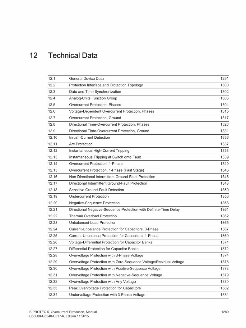
12.1 General Device Data 1291
12.2 Protection Interface and Protection Topology 130012.3 Date and Time Synchronization 1302
12.4 Analog-Units Function Group 130312.5 Overcurrent Protection, Phases 1304
12.6 Voltage-Dependent Overcurrent Protection, Phases 131512.7 Overcurrent Protection, Ground 1317
12.8 Directional Time-Overcurrent Protection, Phases 132812.9 Directional Time-Overcurrent Protection, Ground 133112.10 Inrush-Current Detection 133612.11 Arc Protection 1337
12.12 Instantaneous High-Current Tripping 133812.13 Instantaneous Tripping at Switch onto Fault 1339
12.14 Overcurrent Protection, 1-Phase 134012.15 Overcurrent Protection, 1-Phase (Fast Stage) 1345
12.16 Non-Directional Intermittent Ground-Fault Protection 134612.17 Directional Intermittent Ground-Fault Protection 1348
12.18 Sensitive Ground-Fault Detection 135012.19 Undercurrent Protection 135612.20 Negative-Sequence Protection 135812.21 Directional Negative-Sequence Protection with Definite-Time Delay 136112.22 Thermal Overload Protection 1362
12.23 Unbalanced-Load Protection 136512.24 Current-Unbalance Protection for Capacitors, 3-Phase 1367
12.25 Current-Unbalance Protection for Capacitors, 1-Phase 136912.26 Voltage-Differential Protection for Capacitor Banks 1371
12.27 Differential Protection for Capacitor Banks 137212.28 Overvoltage Protection with 3-Phase Voltage 1374
12.29 Overvoltage Protection with Zero-Sequence Voltage/Residual Voltage 137612.30 Overvoltage Protection with Positive-Sequence Voltage 1378
12.31 Overvoltage Protection with Negative-Sequence Voltage 137912.32 Overvoltage Protection with Any Voltage 1380
12.33 Peak Overvoltage Protection for Capacitors 138212.34 Undervoltage Protection with 3-Phase Voltage 1384
12
SIPROTEC 5, Overcurrent Protection, Manual 1289C53000-G5040-C017-6, Edition 11.2015

12.35 Undervoltage Protection with Positive-Sequence Voltage 1387
12.36 Undervoltage Protection with Any Voltage 138912.37 Overfrequency Protection 1391
12.38 Underfrequency Protection 139212.39 Rate of Frequency Change Protection 1393
12.40 3-Phase Power Protection (P,Q) 139412.41 Reverse-Power Protection 1395
12.42 Overexcitation Protection 139612.43 Undervoltage-Controlled Reactive-Power Protection 1398
12.44 Circuit-Breaker Failure Protection 140012.45 Circuit-Breaker Restrike Protection 1402
12.46 Restricted Ground-Fault Protection 140312.47 External Trip Initiation 1405
12.48 Automatic Reclosing 140612.49 Fault Locator 1407
12.50 Temperature Supervision 140812.51 Current-Jump Detection 1409
12.52 Voltage-Jump Detection 141012.53 Synchronization Function 141112.54 Voltage Controller 141312.55 Current-Balance Supervision 141512.56 Voltage-Balance Supervision 141612.57 Current-Sum Supervision 141712.58 Voltage-Sum Supervision 141812.59 Current Phase-Rotation Supervision 141912.60 Voltage Phase-Rotation Reversal 142012.61 Trip-Circuit Supervision 142112.62 Analog Channel Supervision via Fast Current Sum 142212.63 Measuring-Voltage Failure Detection 1423
12.64 Voltage-Transformer Circuit Breaker 142512.65 Operational Measured Values and Statistical Values 142612.66 Energy Values 1430
12.67 Phasor Measurement Unit 143112.68 Circuit-Breaker Wear Monitoring 1432
12.69 CFC 1433
Technical Data
1290 SIPROTEC 5, Overcurrent Protection, ManualC53000-G5040-C017-6, Edition 11.2015
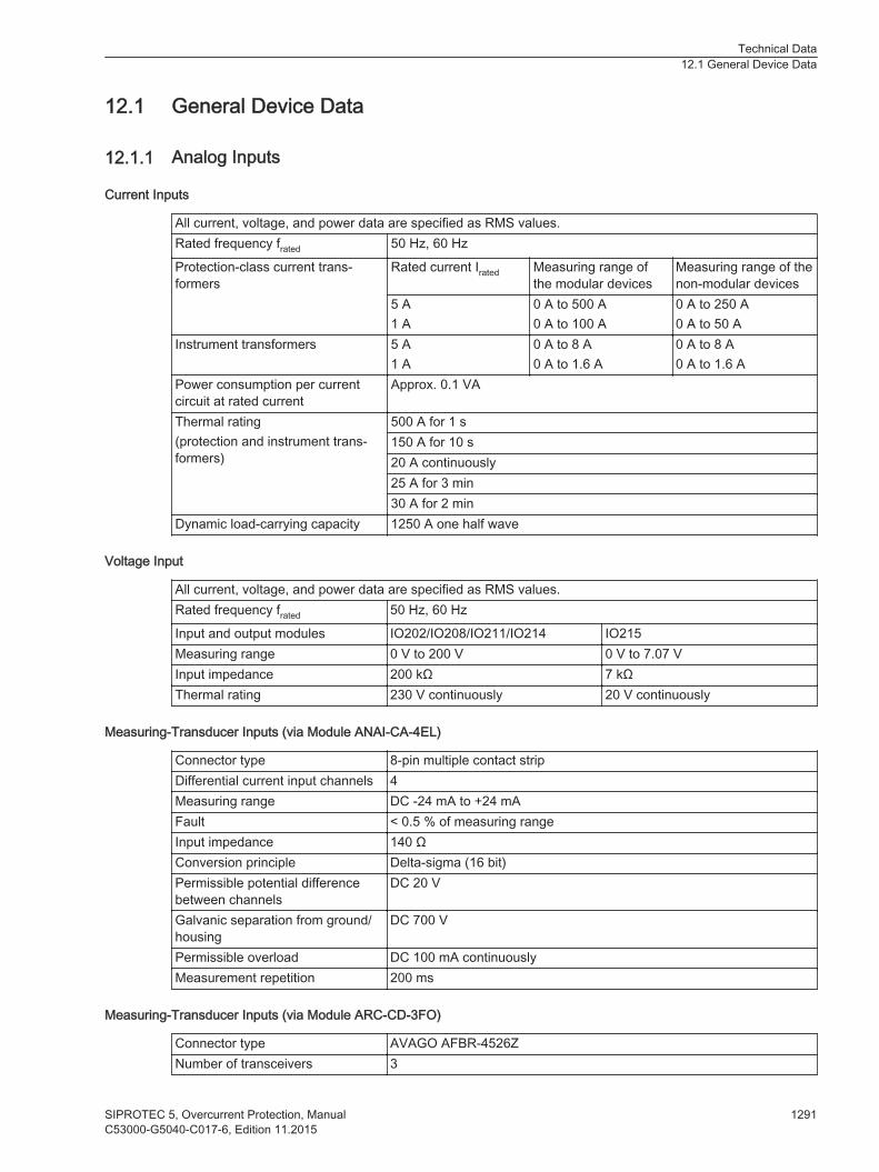
General Device Data
Analog Inputs
Current Inputs
All current, voltage, and power data are specified as RMS values.Rated frequency frated 50 Hz, 60 Hz
Protection-class current trans-formers
Rated current Irated Measuring range ofthe modular devices
Measuring range of thenon-modular devices
5 A1 A
0 A to 500 A0 A to 100 A
0 A to 250 A0 A to 50 A
Instrument transformers 5 A1 A
0 A to 8 A0 A to 1.6 A
0 A to 8 A0 A to 1.6 A
Power consumption per currentcircuit at rated current
Approx. 0.1 VA
Thermal rating(protection and instrument trans-formers)
500 A for 1 s150 A for 10 s20 A continuously25 A for 3 min30 A for 2 min
Dynamic load-carrying capacity 1250 A one half wave
Voltage Input
All current, voltage, and power data are specified as RMS values.Rated frequency frated 50 Hz, 60 Hz
Input and output modules IO202/IO208/IO211/IO214 IO215Measuring range 0 V to 200 V 0 V to 7.07 VInput impedance 200 kΩ 7 kΩThermal rating 230 V continuously 20 V continuously
Measuring-Transducer Inputs (via Module ANAI-CA-4EL)
Connector type 8-pin multiple contact stripDifferential current input channels 4Measuring range DC -24 mA to +24 mAFault < 0.5 % of measuring rangeInput impedance 140 ΩConversion principle Delta-sigma (16 bit)Permissible potential differencebetween channels
DC 20 V
Galvanic separation from ground/housing
DC 700 V
Permissible overload DC 100 mA continuouslyMeasurement repetition 200 ms
Measuring-Transducer Inputs (via Module ARC-CD-3FO)
Connector type AVAGO AFBR-4526ZNumber of transceivers 3
12.1
12.1.1
Technical Data12.1 General Device Data
SIPROTEC 5, Overcurrent Protection, Manual 1291C53000-G5040-C017-6, Edition 11.2015

Fiber type Polymer Optical Fiber (POF) 1 mmReceiverMaximum -10 dBm ± 2 dBmMinimum -40 dBm ± 2 dBmSpectrum 400 nm to 1100 nmAttenuation In the case of plastic optical fibers, you can expect a path attenuation of
0.2 dB/m Additional attenuation comes from the plug and sensor head.Optical budget 1 Minimal 25 dBAnalog sampling rate 16 kHzADC type 10-bit successive approximationTransmitterType LEDWavelength λ = 650 nmTransmit power Minimum 0 dBm
Maximum 2 dBmNumerical aperture 0.5 2
Signal rate connection test 1 pulse per secondPulse duration connection test 11 μsComment:1 All values in combination with sensors approved by Siemens.2 Numerical aperture (NA = sin θ (launch angle))
High-Speed Measuring-Transducer Inputs, Voltage/Current (via IO212)
iiNOTE
Due to possible EMC interference, pay attention to ensure that only the connections for current or forvoltage are used on the device.Use shielded cables.
Table 12-1 High-Speed Measuring-Transducer Inputs, Voltage
Differential voltage input channels 828
Measuring range DC -10 V to +10 VFault < 0.5 % of the measuring rangeInput impedance 48 kΩConversion principle Delta-sigma (16 bit)Permissible potential differencebetween channels
DC 3.5 kV
Galvanic separation from ground/housing
DC 3.5 kV
Permissible overload DC 20 V continuouslyMeasurement repetition 62.5 μs
Table 12-2 High-Speed Measuring-Transducer Inputs, Current
Differential current input channels 829
Measuring range DC -20 mA to +20 mA
28 The IO212 has 8 high-speed measuring-transducer inputs. They can be used either as a voltage or as current input.29 The IO212 has 8 high-speed measuring-transducer inputs. They can be used either as a voltage or as current input.
Technical Data12.1 General Device Data
1292 SIPROTEC 5, Overcurrent Protection, ManualC53000-G5040-C017-6, Edition 11.2015
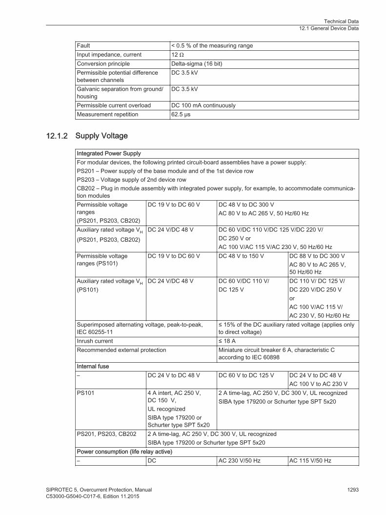
Fault < 0.5 % of the measuring rangeInput impedance, current 12 ΩConversion principle Delta-sigma (16 bit)Permissible potential differencebetween channels
DC 3.5 kV
Galvanic separation from ground/housing
DC 3.5 kV
Permissible current overload DC 100 mA continuouslyMeasurement repetition 62.5 μs
Supply Voltage
Integrated Power SupplyFor modular devices, the following printed circuit-board assemblies have a power supply:PS201 – Power supply of the base module and of the 1st device rowPS203 – Voltage supply of 2nd device rowCB202 – Plug in module assembly with integrated power supply, for example, to accommodate communica-tion modulesPermissible voltageranges(PS201, PS203, CB202)
DC 19 V to DC 60 V DC 48 V to DC 300 VAC 80 V to AC 265 V, 50 Hz/60 Hz
Auxiliary rated voltage VH
(PS201, PS203, CB202)DC 24 V/DC 48 V DC 60 V/DC 110 V/DC 125 V/DC 220 V/
DC 250 V orAC 100 V/AC 115 V/AC 230 V, 50 Hz/60 Hz
Permissible voltageranges (PS101)
DC 19 V to DC 60 V DC 48 V to 150 V DC 88 V to DC 300 VAC 80 V to AC 265 V,50 Hz/60 Hz
Auxiliary rated voltage VH
(PS101)DC 24 V/DC 48 V DC 60 V/DC 110 V/
DC 125 VDC 110 V/ DC 125 V/DC 220 V/DC 250 VorAC 100 V/AC 115 V/AC 230 V, 50 Hz/60 Hz
Superimposed alternating voltage, peak-to-peak,IEC 60255-11
≤ 15% of the DC auxiliary rated voltage (applies onlyto direct voltage)
Inrush current ≤ 18 ARecommended external protection Miniature circuit breaker 6 A, characteristic C
according to IEC 60898Internal fuse– DC 24 V to DC 48 V DC 60 V to DC 125 V DC 24 V to DC 48 V
AC 100 V to AC 230 VPS101 4 A intert, AC 250 V,
DC 150 V,UL recognizedSIBA type 179200 orSchurter type SPT 5x20
2 A time-lag, AC 250 V, DC 300 V, UL recognizedSIBA type 179200 or Schurter type SPT 5x20
PS201, PS203, CB202 2 A time-lag, AC 250 V, DC 300 V, UL recognizedSIBA type 179200 or Schurter type SPT 5x20
Power consumption (life relay active)– DC AC 230 V/50 Hz AC 115 V/50 Hz
12.1.2
Technical Data12.1 General Device Data
SIPROTEC 5, Overcurrent Protection, Manual 1293C53000-G5040-C017-6, Edition 11.2015
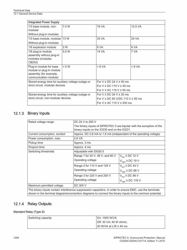
Integrated Power Supply1/3 base module, non-modularWithout plug-in modules
7.0 W 16 VA 12.5 VA
1/3 base module, modularWithout plug-in modules
13 W 33 VA 24 VA
1/6 expansion module 3 W 6 VA 6 VA1/6 plug-in moduleassembly without plug-inmodules (modulesCB202)
3.5 W 14 VA 7 VA
Plug-in module for basemodule or plug-in moduleassembly (for example,communication module)
< 5 W < 6 VA < 6 VA
Stored-energy time for auxiliary voltage outage orshort circuit, modular devices
For V ≥ DC 24 V ≥ 50 msFor V ≥ DC 110 V ≥ 50 msFor V ≥ AC 115 V ≥ 50 ms
Stored-energy time for auxiliary voltage outage orshort circuit, non-modular devices
For V ≥ DC 24 V ≥ 20 msFor V ≥ DC 60 V/DC 110 V ≥ 50 msFor V ≥ AC 115 V ≥ 200 ms
Binary Inputs
Rated voltage range DC 24 V to 250 VThe binary inputs of SIPROTEC 5 are bipolar with the exception of thebinary inputs on the IO230 and on the IO231.
Current consumption, excited Approx. DC 0.6 mA to 1.8 mA (independent of the operating voltage)Power consumption, max. 0.6 VAPickup time Approx. 3 msDropout time Approx. 4 msSwitching thresholds Adjustable with DIGSI 5
Range 1 for 24 V, 48 V, and 60 VOperating voltage
Vlow ≤ DC 10 VVhigh ≥ DC 19 V
Range 2 for 110 V and 125 VOperating voltage
Vlow ≤ DC 44 VVhigh ≥ DC 88 V
Range 3 for 220 V and 250 VOperating voltage
Vlow ≤ DC 88 VVhigh ≥ DC 176 V
Maximum permitted voltage DC 300 VThe binary inputs contain interference suppression capacitors. In order to ensure EMC, use the terminalsshown in the terminal diagrams/connection diagrams to connect the binary inputs to the common potential.
Relay Outputs
Standard Relay (Type S)
Switching capacity On: 1000 W/VAOff: 30 VA; 40 W ohmic;30 W/VA at L/R ≤ 40 ms
12.1.3
12.1.4
Technical Data12.1 General Device Data
1294 SIPROTEC 5, Overcurrent Protection, ManualC53000-G5040-C017-6, Edition 11.2015
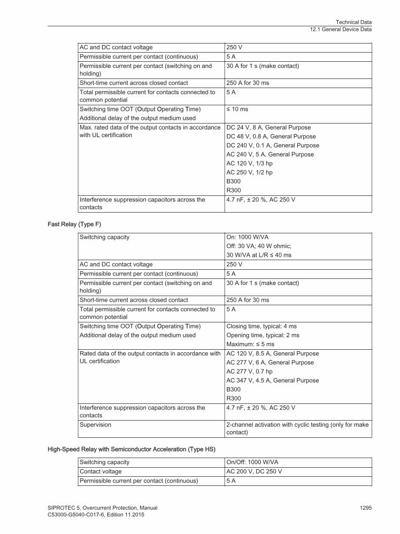
AC and DC contact voltage 250 VPermissible current per contact (continuous) 5 APermissible current per contact (switching on andholding)
30 A for 1 s (make contact)
Short-time current across closed contact 250 A for 30 msTotal permissible current for contacts connected tocommon potential
5 A
Switching time OOT (Output Operating Time)Additional delay of the output medium used
≤ 10 ms
Max. rated data of the output contacts in accordancewith UL certification
DC 24 V, 8 A, General PurposeDC 48 V, 0.8 A, General PurposeDC 240 V, 0.1 A, General PurposeAC 240 V, 5 A, General PurposeAC 120 V, 1/3 hpAC 250 V, 1/2 hpB300R300
Interference suppression capacitors across thecontacts
4.7 nF, ± 20 %, AC 250 V
Fast Relay (Type F)
Switching capacity On: 1000 W/VAOff: 30 VA; 40 W ohmic;30 W/VA at L/R ≤ 40 ms
AC and DC contact voltage 250 VPermissible current per contact (continuous) 5 APermissible current per contact (switching on andholding)
30 A for 1 s (make contact)
Short-time current across closed contact 250 A for 30 msTotal permissible current for contacts connected tocommon potential
5 A
Switching time OOT (Output Operating Time)Additional delay of the output medium used
Closing time, typical: 4 msOpening time, typical: 2 msMaximum: ≤ 5 ms
Rated data of the output contacts in accordance withUL certification
AC 120 V, 8.5 A, General PurposeAC 277 V, 6 A, General PurposeAC 277 V, 0.7 hpAC 347 V, 4.5 A, General PurposeB300R300
Interference suppression capacitors across thecontacts
4.7 nF, ± 20 %, AC 250 V
Supervision 2-channel activation with cyclic testing (only for makecontact)
High-Speed Relay with Semiconductor Acceleration (Type HS)
Switching capacity On/Off: 1000 W/VAContact voltage AC 200 V, DC 250 VPermissible current per contact (continuous) 5 A
Technical Data12.1 General Device Data
SIPROTEC 5, Overcurrent Protection, Manual 1295C53000-G5040-C017-6, Edition 11.2015

Permissible current per contact (switching on andholding)
30 A for 1 s (make contact)
Short-time current across closed contact 250 A for 30 msTotal permissible current for contacts connected tocommon potential
5 A
Switching time OOT (Output Operating Time)Additional delay of the output medium used
Closing time, typical: 0.2 msOpening time, typical: 6 msMaximum: ≤ 9 ms
Rated data of the output contacts in accordance withUL certification
B150Q300
Power Relay (for Direct Control of Motor Switches)
Switching capacity for permanent and periodic operation250 V/4.0 A220 V/4.5 A110 V/5.0 A60 V/5.0 A48 V/5.0 A24 V/5.0 A
1000 W1000 W550 W300 W240 W120 W
In order to prevent any damage, the external protec-tion circuit must switch off the motor in case the rotoris blocked.
Turn on switching power for 30 s, recovery time until switching on again is 15 minutes.For short-term switching operations, an impulse/pause ratio of 3 % must be considered.100 V/9.0 A60 V/10.0 A48 V/10.0 A24 V/10.0 A
1000 W600 W480 W240 W
Continuous and inching operation is not permitted.In order to prevent any damage, the external protec-tion circuit must switch off the motor in case the rotoris blocked.
AC and DC contact voltage 250 VPermissible continuous current per contact 5 APermissible current per contact (switching on andholding)
30 A for 1 s
Short-time current across closed contact 250 A for 30 msTotal permissible current for contacts connected tocommon potential
5 A
Switching time OOT (Output Operating Time)Additional delay of the output medium used
≤ 16 ms
Rated data of the output contacts in accordance withUL certification
DC 300 V, 10 A, ResistiveDC 250 V, 1 hp motor - 30 s ON, 15 min OFFDC 110 V, 3/4 hp motor - 30 s ON, 15 min OFFDC 60 V, 1/2 hp motor - 30 s ON, 15 min OFFDC 48 V, 1/3 hp motor - 30 s ON, 15 min OFFDC 24 V, 1/6 hp motor - 30 s ON, 15 min OFF
Interference suppression capacitors across thecontacts
4.7 nF, ± 20 %, AC 250 V
The power relays operate in interlocked mode, that is, only one relay of each switching pair picks up at atime thereby avoiding a power-supply short circuit.
Technical Data12.1 General Device Data
1296 SIPROTEC 5, Overcurrent Protection, ManualC53000-G5040-C017-6, Edition 11.2015
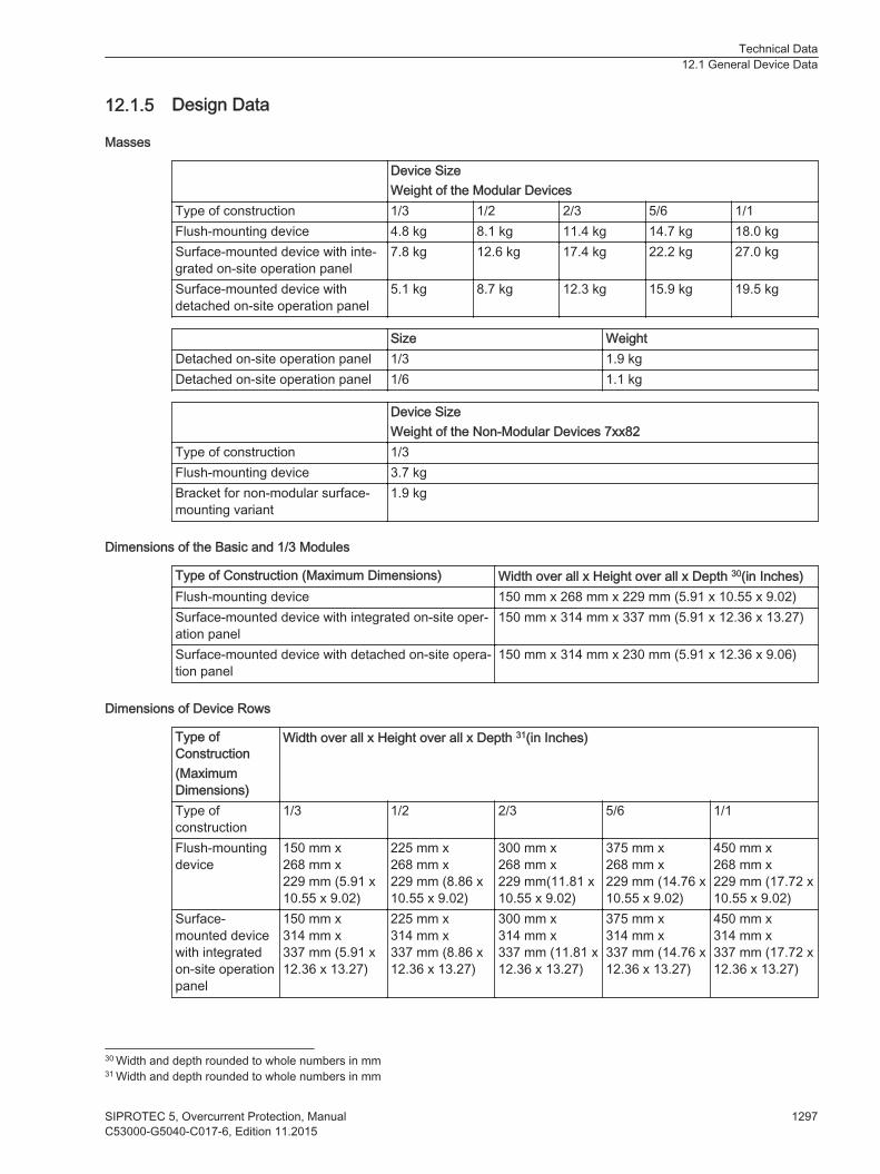
Design Data
Masses
Device SizeWeight of the Modular Devices
Type of construction 1/3 1/2 2/3 5/6 1/1Flush-mounting device 4.8 kg 8.1 kg 11.4 kg 14.7 kg 18.0 kgSurface-mounted device with inte-grated on-site operation panel
7.8 kg 12.6 kg 17.4 kg 22.2 kg 27.0 kg
Surface-mounted device withdetached on-site operation panel
5.1 kg 8.7 kg 12.3 kg 15.9 kg 19.5 kg
Size WeightDetached on-site operation panel 1/3 1.9 kgDetached on-site operation panel 1/6 1.1 kg
Device SizeWeight of the Non-Modular Devices 7xx82
Type of construction 1/3Flush-mounting device 3.7 kgBracket for non-modular surface-mounting variant
1.9 kg
Dimensions of the Basic and 1/3 Modules
Type of Construction (Maximum Dimensions) Width over all x Height over all x Depth 30(in Inches)Flush-mounting device 150 mm x 268 mm x 229 mm (5.91 x 10.55 x 9.02)Surface-mounted device with integrated on-site oper-ation panel
150 mm x 314 mm x 337 mm (5.91 x 12.36 x 13.27)
Surface-mounted device with detached on-site opera-tion panel
150 mm x 314 mm x 230 mm (5.91 x 12.36 x 9.06)
Dimensions of Device Rows
Type ofConstruction(MaximumDimensions)
Width over all x Height over all x Depth 31(in Inches)
Type ofconstruction
1/3 1/2 2/3 5/6 1/1
Flush-mountingdevice
150 mm x268 mm x229 mm (5.91 x10.55 x 9.02)
225 mm x268 mm x229 mm (8.86 x10.55 x 9.02)
300 mm x268 mm x229 mm(11.81 x10.55 x 9.02)
375 mm x268 mm x229 mm (14.76 x10.55 x 9.02)
450 mm x268 mm x229 mm (17.72 x10.55 x 9.02)
Surface-mounted devicewith integratedon-site operationpanel
150 mm x314 mm x337 mm (5.91 x12.36 x 13.27)
225 mm x314 mm x337 mm (8.86 x12.36 x 13.27)
300 mm x314 mm x337 mm (11.81 x12.36 x 13.27)
375 mm x314 mm x337 mm (14.76 x12.36 x 13.27)
450 mm x314 mm x337 mm (17.72 x12.36 x 13.27)
12.1.5
30 Width and depth rounded to whole numbers in mm31 Width and depth rounded to whole numbers in mm
Technical Data12.1 General Device Data
SIPROTEC 5, Overcurrent Protection, Manual 1297C53000-G5040-C017-6, Edition 11.2015

Type ofConstruction(MaximumDimensions)
Width over all x Height over all x Depth 31(in Inches)
Surface-mounted devicewith detachedon-site operationpanel
150 mm x314 mm x230 mm (5.91 x12.36 x 9.06)
225 mm x314 mm x230 mm (8.86 x12.36 x 9.06)
300 mm x314 mm x230 mm (11.81 x12.36 x 9.06)
375 mm x314 mm x230 mm (14.76 x12.36 x 9.06)
450 mm x314 mm x230 mm (17.72 x12.36 x 9.06)
Expansion Module Dimensions
Type of Construction (Maximum Dimensions) Width x Height x Depth 32 (in Inches)Flush-mounting device 75 mm x 268 mm x 229 mm (2.95 x 10.55 x 9.02)Surface-mounted device with integrated on-site oper-ation panel
75 mm x 314 mm x 337 mm (2.95 x 12.36 x 13.27)
Surface-mounted device with detached on-site opera-tion panel
75 mm x 314 mm x 230 mm (2.95 x 12.36 x 9.06)
Plug-In Module Dimensions
Type of Construction (Maximum Dimensions) Width x Height x Depth (in Inches)USART-Ax-xEL, ETH-Bx-xEL 61 mm x 45 mm x 120.5 mm (2.4 x 1.77 x 4.74)USART-Ax-xFO, ETH-Bx-xFO (without protectioncover)
61 mm x 45 mm x 132.5 mm (2.4 x 1.77 x 5.22)
ANAI-CA-4EL 61 mm x 45 mm x 119.5 mm (2.4 x 1.77 x 4.7)ARC-CD-3FO 61 mm x 45 mm x 120.5 mm (2.4 x 1.77 x 4.74)
Minimum Bending Radii of the Connecting Cables Between the On-Site Operation Panel and the Base Module
Fiber-optic cable R = 50 mmPay attention to the length of the cable protectionsleeve, which you must also include in calculations.
D-Sub cable R = 50 mm (minimum bending radius)
Degree of Protection to IEC 60529
For equipment in the surface-mounting housing IP50For equipment in the flush-mounting housing Front IP51
Back side of the modular devices IP50Back side of the non-modular devices IP40
For operator protection IP2x for current terminal (installed removed)IP1x for voltage terminal (removed/without cover)IP2x for voltage terminal (removed/with cover)IP2x for voltage terminal (installed)
Degree of pollution, IEC 60255-27 2Maximum altitude above sea level 2000 m (6561.68 ft)
31 Width and depth rounded to whole numbers in mm32 Width and depth rounded to whole numbers in mm
Technical Data12.1 General Device Data
1298 SIPROTEC 5, Overcurrent Protection, ManualC53000-G5040-C017-6, Edition 11.2015
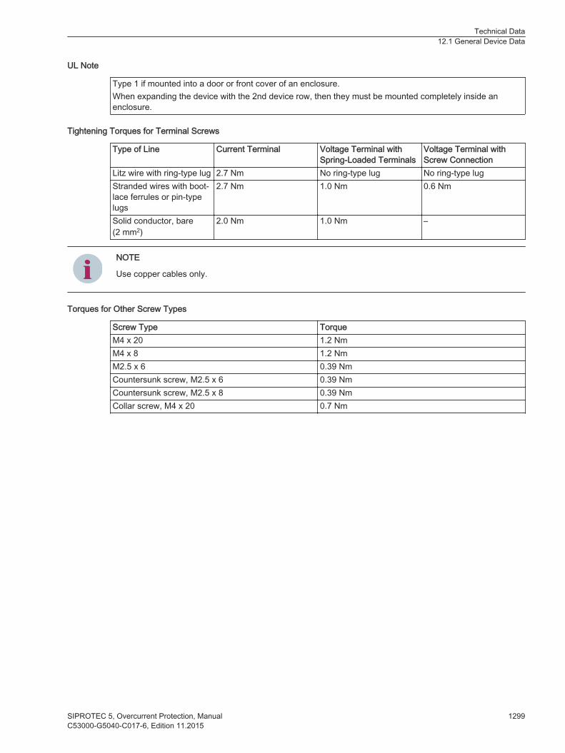
UL Note
Type 1 if mounted into a door or front cover of an enclosure.When expanding the device with the 2nd device row, then they must be mounted completely inside anenclosure.
Tightening Torques for Terminal Screws
Type of Line Current Terminal Voltage Terminal withSpring-Loaded Terminals
Voltage Terminal withScrew Connection
Litz wire with ring-type lug 2.7 Nm No ring-type lug No ring-type lugStranded wires with boot-lace ferrules or pin-typelugs
2.7 Nm 1.0 Nm 0.6 Nm
Solid conductor, bare(2 mm2)
2.0 Nm 1.0 Nm –
iiNOTE
Use copper cables only.
Torques for Other Screw Types
Screw Type TorqueM4 x 20 1.2 NmM4 x 8 1.2 NmM2.5 x 6 0.39 NmCountersunk screw, M2.5 x 6 0.39 NmCountersunk screw, M2.5 x 8 0.39 NmCollar screw, M4 x 20 0.7 Nm
Technical Data12.1 General Device Data
SIPROTEC 5, Overcurrent Protection, Manual 1299C53000-G5040-C017-6, Edition 11.2015

Protection Interface and Protection Topology
Setting Values
Mode OnOff
PPS Synchronization Telegr. and PPSTelegr. or PPSPPS synchronization off
Blocking of the unbalancedruntimes
YesNo
Maximum signal runtime threshold 0.1 ms to 30.0 ms Increments of 0.1 msMaximum runtime difference 0.000 ms to 3.000 ms Increments of 0.001 msFailure indication after 0.05 s to 2.00 s Increments of 0.01 sFailure indication after 0.0 s to 6.0 s Increments of 0.1 sMax. error rate/h 0.000 % to 100.000 % Increments of 0.001 %Max. error rate/min 0.000 % to 100.000 % Increments of 0.001 %PPS failure indication after 0.5 s to 60.0 s Increments of 0.1 s
Transmission Rate
Direct connection:Transmission rate 2048 kbit/sConnection via communication networks:Supported network interfaces G703.1 with 64 kBit/s
G703-T1 with 1.455 MBit/sG703-E1 with 2.048 MBit/sX.21 with 64 kBit/s or 128 kBit/s or 512 kBit/sPilot wires with 128 kbit/s
Transmission rate 64 kBit/s at G703.11.455 MBit/s at G703-T12.048 MBit/s at G703-E1512 kBit/s or 128 kBit/s or 64 kBit/s at X.21128 kBit/s for pilot wires
Transmission Times
Priority 1Response time, total approx.For 2 ends Minimum 8 ms
Typical 10 msFor 3 ends Minimum 10 ms
Typical 14 msFor 6 ends Minimum 15 ms
Typical 18 msDropout times, total approx.For 2 ends Typical 20 msFor 3 ends Typical 20 msFor 6 ends Typical 26 ms
12.2
Technical Data12.2 Protection Interface and Protection Topology
1300 SIPROTEC 5, Overcurrent Protection, ManualC53000-G5040-C017-6, Edition 11.2015

Priority 2Response time, total approx.For 2 ends Minimum 9 ms
Typical 16 msFor 3 ends Minimum 12 ms
Typical 18 msFor 6 ends Minimum 17 ms
Typical 23 msDropout times, total approx.For 2 ends Typical 24 msFor 3 ends Typical 25 msFor 6 ends Typical 32 ms
Priority 333
Response time, total approx.For 2 ends Minimum
Typical 100 msFor 3 ends Minimum
Typical 150 msFor 6 ends Minimum
Typical 200 msDropout times, total approx.For 2 ends Typical 100 msFor 3 ends Typical 150 msFor 6 ends Typical 200 ms
33 Times cannot be determined because the signals are transmitted in fragments.
Technical Data12.2 Protection Interface and Protection Topology
SIPROTEC 5, Overcurrent Protection, Manual 1301C53000-G5040-C017-6, Edition 11.2015

Date and Time Synchronization
Date format DD.MM.YYYY (Europe)MM/DD/YYYY (USA)YYYY-MM-DD (China)
Time source 1, time source 2 NoneIRIG-B 002(003)IRIG-B 006(007)IRIG-B 005(004) with extension according toIEEE C37.118-2005DCF77PI (protection interface)34
SNTPIEC 60870-5-103DNP3IEEE 1588
Time zone 1, time zone 2 LocalUTC
Failure indication after 0 s to 3600 sTime zone and daylight saving time Transfer of PC settings
Manually setting the time zonesTime zone offset with respect to GMT -720 min to 840 minSwitching over to daylight saving time Active
InactiveBeginning of daylight saving time Input: day and timeEnd of daylight saving time Input: day and timeOffset daylight saving time -120 to 120 [steps of 15]
12.3
34 If provided
Technical Data12.3 Date and Time Synchronization
1302 SIPROTEC 5, Overcurrent Protection, ManualC53000-G5040-C017-6, Edition 11.2015
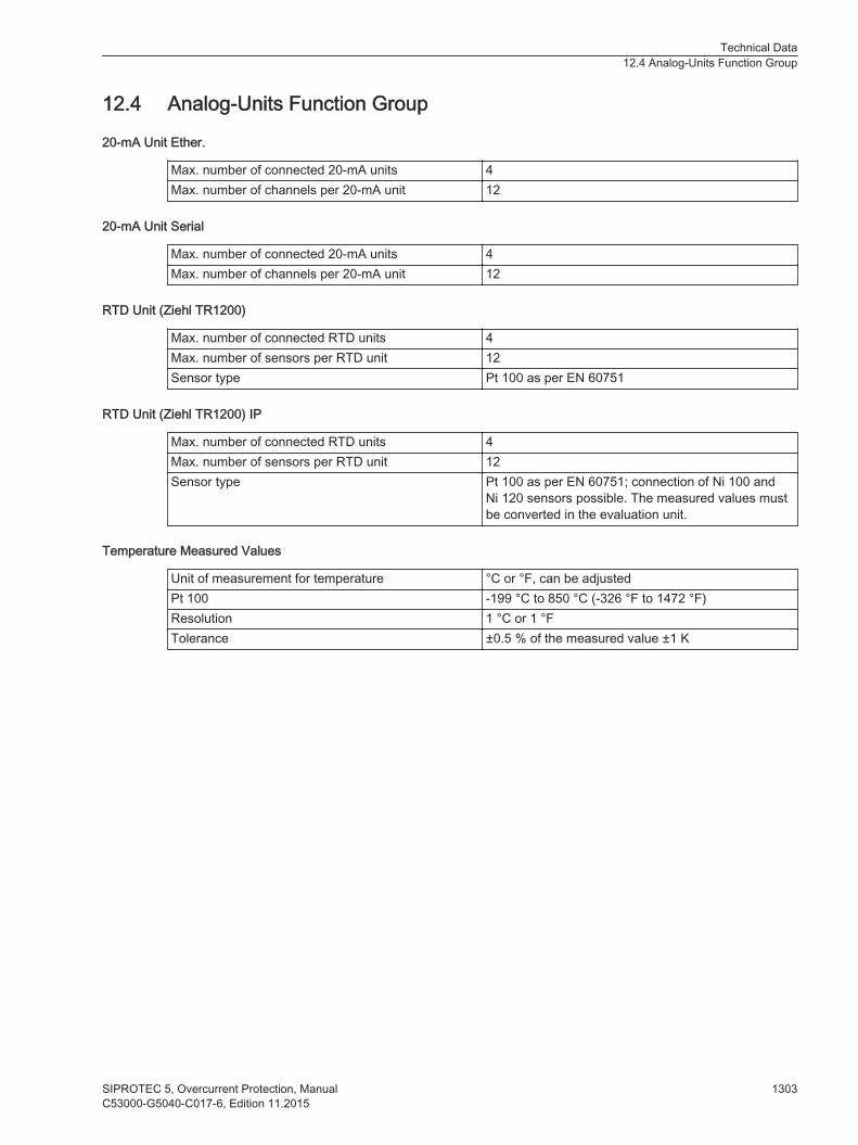
Analog-Units Function Group
20-mA Unit Ether.
Max. number of connected 20-mA units 4Max. number of channels per 20-mA unit 12
20-mA Unit Serial
Max. number of connected 20-mA units 4Max. number of channels per 20-mA unit 12
RTD Unit (Ziehl TR1200)
Max. number of connected RTD units 4Max. number of sensors per RTD unit 12Sensor type Pt 100 as per EN 60751
RTD Unit (Ziehl TR1200) IP
Max. number of connected RTD units 4Max. number of sensors per RTD unit 12Sensor type Pt 100 as per EN 60751; connection of Ni 100 and
Ni 120 sensors possible. The measured values mustbe converted in the evaluation unit.
Temperature Measured Values
Unit of measurement for temperature °C or °F, can be adjustedPt 100 -199 °C to 850 °C (-326 °F to 1472 °F)Resolution 1 °C or 1 °FTolerance ±0.5 % of the measured value ±1 K
12.4
Technical Data12.4 Analog-Units Function Group
SIPROTEC 5, Overcurrent Protection, Manual 1303C53000-G5040-C017-6, Edition 11.2015
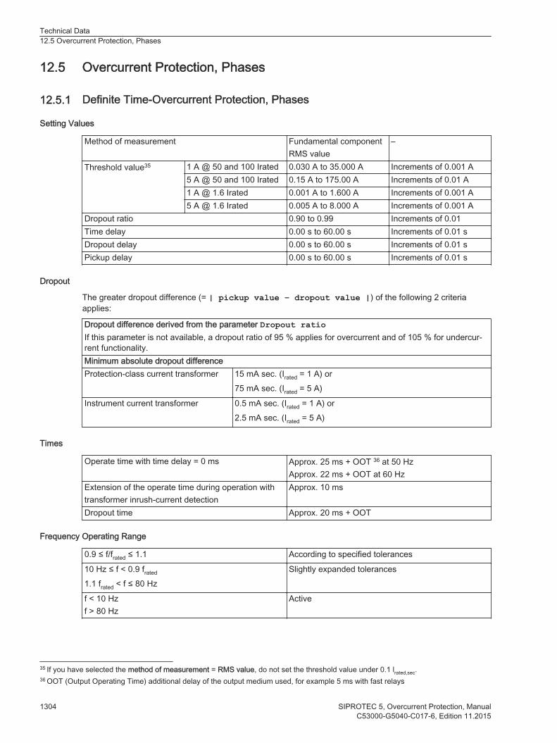
Overcurrent Protection, Phases
Definite Time-Overcurrent Protection, Phases
Setting Values
Method of measurement Fundamental componentRMS value
–
Threshold value35 1 A @ 50 and 100 Irated 0.030 A to 35.000 A Increments of 0.001 A5 A @ 50 and 100 Irated 0.15 A to 175.00 A Increments of 0.01 A1 A @ 1.6 Irated 0.001 A to 1.600 A Increments of 0.001 A5 A @ 1.6 Irated 0.005 A to 8.000 A Increments of 0.001 A
Dropout ratio 0.90 to 0.99 Increments of 0.01Time delay 0.00 s to 60.00 s Increments of 0.01 sDropout delay 0.00 s to 60.00 s Increments of 0.01 sPickup delay 0.00 s to 60.00 s Increments of 0.01 s
Dropout
The greater dropout difference (= | pickup value – dropout value |) of the following 2 criteriaapplies:
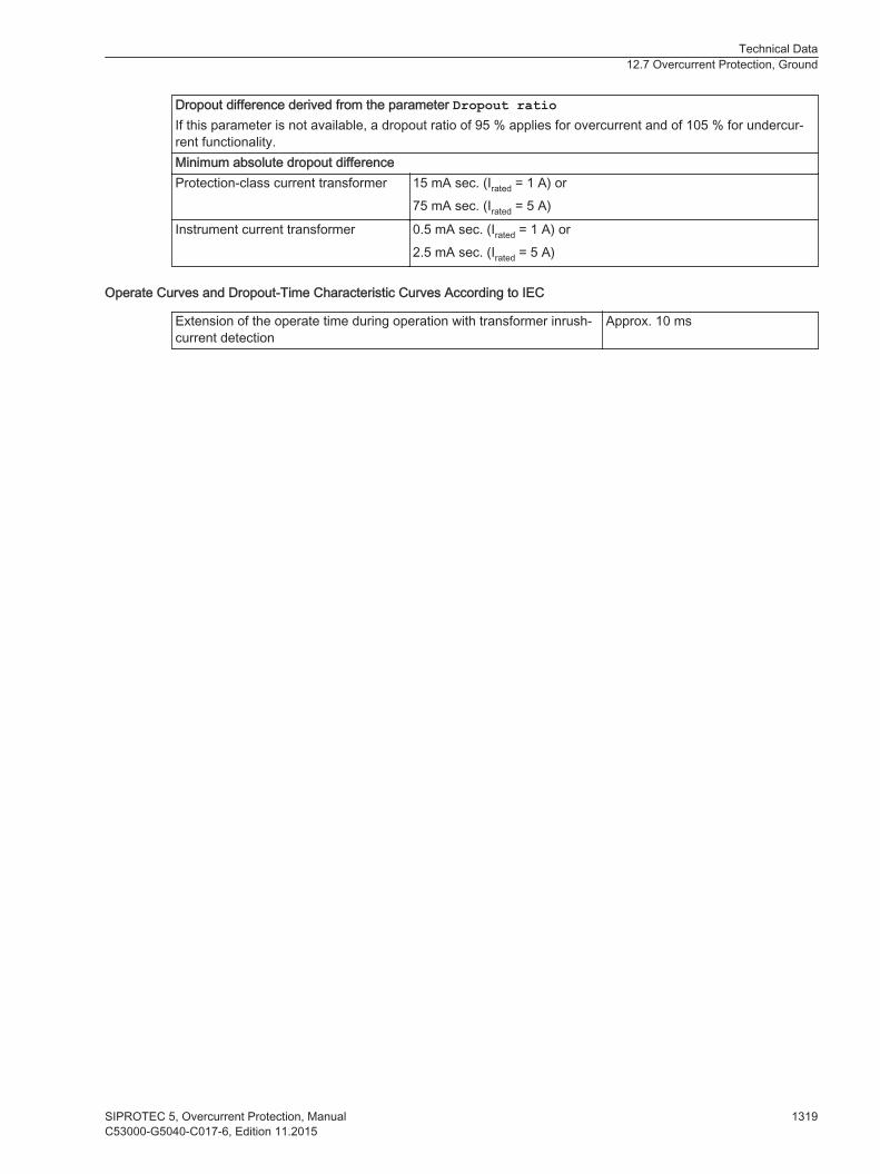
Dropout difference derived from the parameter Dropout ratioIf this parameter is not available, a dropout ratio of 95 % applies for overcurrent and of 105 % for undercur-rent functionality.Minimum absolute dropout differenceProtection-class current transformer 15 mA sec. (Irated = 1 A) or
75 mA sec. (Irated = 5 A)
Instrument current transformer 0.5 mA sec. (Irated = 1 A) or2.5 mA sec. (Irated = 5 A)
Times
Operate time with time delay = 0 ms Approx. 25 ms + OOT 36 at 50 HzApprox. 22 ms + OOT at 60 Hz
Extension of the operate time during operation withtransformer inrush-current detection
Approx. 10 ms
Dropout time Approx. 20 ms + OOT
Frequency Operating Range
0.9 ≤ f/frated ≤ 1.1 According to specified tolerances
10 Hz ≤ f < 0.9 frated
1.1 frated < f ≤ 80 HzSlightly expanded tolerances
f < 10 Hzf > 80 Hz
Active
12.5
12.5.1
35 If you have selected the method of measurement = RMS value, do not set the threshold value under 0.1 lrated,sec.36 OOT (Output Operating Time) additional delay of the output medium used, for example 5 ms with fast relays
Technical Data12.5 Overcurrent Protection, Phases
1304 SIPROTEC 5, Overcurrent Protection, ManualC53000-G5040-C017-6, Edition 11.2015
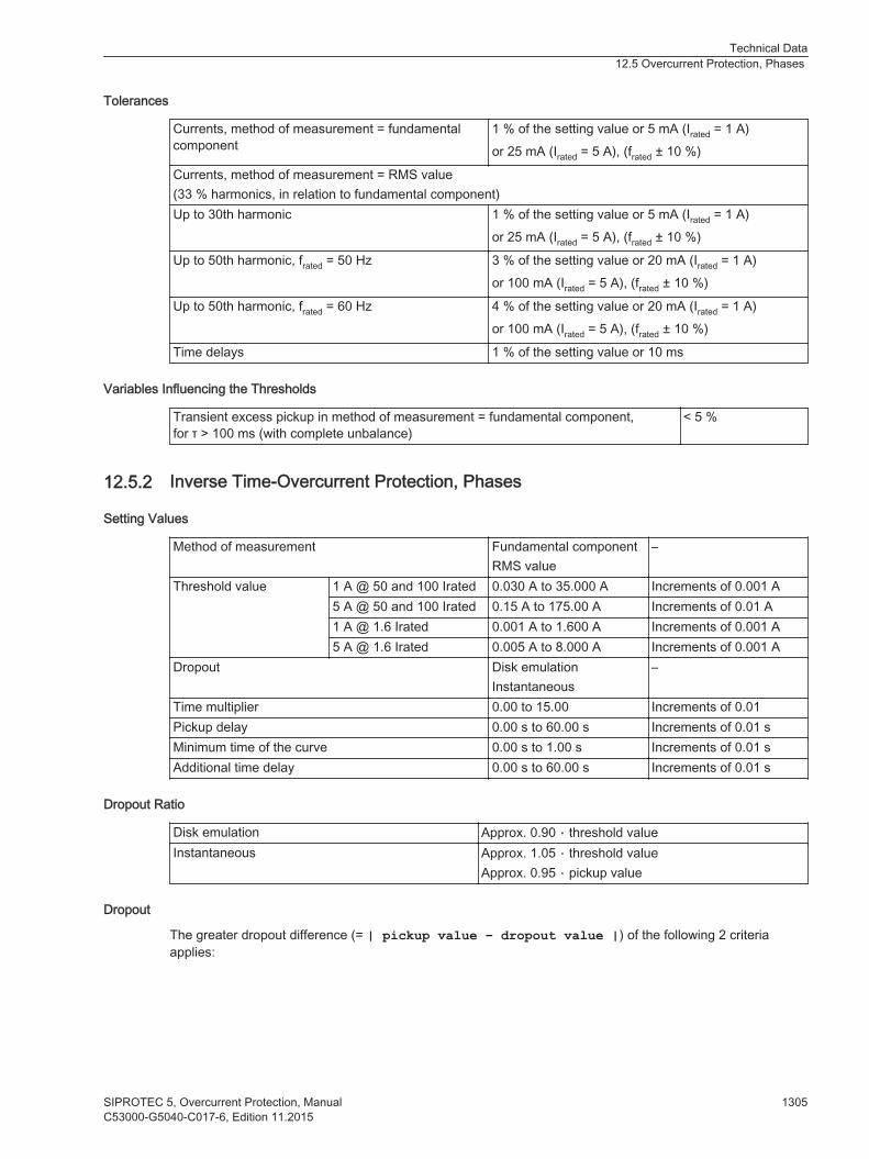
Tolerances
Currents, method of measurement = fundamentalcomponent
1 % of the setting value or 5 mA (Irated = 1 A)or 25 mA (Irated = 5 A), (frated ± 10 %)
Currents, method of measurement = RMS value(33 % harmonics, in relation to fundamental component)Up to 30th harmonic 1 % of the setting value or 5 mA (Irated = 1 A)
or 25 mA (Irated = 5 A), (frated ± 10 %)
Up to 50th harmonic, frated = 50 Hz 3 % of the setting value or 20 mA (Irated = 1 A)or 100 mA (Irated = 5 A), (frated ± 10 %)
Up to 50th harmonic, frated = 60 Hz 4 % of the setting value or 20 mA (Irated = 1 A)or 100 mA (Irated = 5 A), (frated ± 10 %)
Time delays 1 % of the setting value or 10 ms
Variables Influencing the Thresholds
Transient excess pickup in method of measurement = fundamental component,for τ > 100 ms (with complete unbalance)
< 5 %
Inverse Time-Overcurrent Protection, Phases
Setting Values
Method of measurement Fundamental componentRMS value
–
Threshold value 1 A @ 50 and 100 Irated 0.030 A to 35.000 A Increments of 0.001 A5 A @ 50 and 100 Irated 0.15 A to 175.00 A Increments of 0.01 A1 A @ 1.6 Irated 0.001 A to 1.600 A Increments of 0.001 A5 A @ 1.6 Irated 0.005 A to 8.000 A Increments of 0.001 A
Dropout Disk emulationInstantaneous
–
Time multiplier 0.00 to 15.00 Increments of 0.01Pickup delay 0.00 s to 60.00 s Increments of 0.01 sMinimum time of the curve 0.00 s to 1.00 s Increments of 0.01 sAdditional time delay 0.00 s to 60.00 s Increments of 0.01 s
Dropout Ratio
Disk emulation Approx. 0.90 ⋅ threshold valueInstantaneous Approx. 1.05 ⋅ threshold value
Approx. 0.95 ⋅ pickup value
Dropout
The greater dropout difference (= | pickup value – dropout value |) of the following 2 criteriaapplies:
12.5.2
Technical Data12.5 Overcurrent Protection, Phases
SIPROTEC 5, Overcurrent Protection, Manual 1305C53000-G5040-C017-6, Edition 11.2015

Dropout difference derived from the parameter Dropout ratioIf this parameter is not available, a dropout ratio of 95 % applies for overcurrent and of 105 % for undercur-rent functionality.Minimum absolute dropout differenceProtection-class current transformer 15 mA sec. (Irated = 1 A) or
75 mA sec. (Irated = 5 A)
Instrument current transformer 0.5 mA sec. (Irated = 1 A) or2.5 mA sec. (Irated = 5 A)
Operate Curves and Dropout-Time Characteristic Curves according to IEC
Extension of the operate time during operation with transformer inrush-current detection
Approx. 10 ms
Technical Data12.5 Overcurrent Protection, Phases
1306 SIPROTEC 5, Overcurrent Protection, ManualC53000-G5040-C017-6, Edition 11.2015

[dwocpki1-080213-01.tif, 1, en_US]
Figure 12-1 Operate Curves and Dropout-Time Characteristic Curves according to IEC
Technical Data12.5 Overcurrent Protection, Phases
SIPROTEC 5, Overcurrent Protection, Manual 1307C53000-G5040-C017-6, Edition 11.2015

[dwocpki2-080213-01.tif, 1, en_US]
Figure 12-2 Operate Curves and Dropout-Time Characteristic Curves According to IEC
Technical Data12.5 Overcurrent Protection, Phases
1308 SIPROTEC 5, Overcurrent Protection, ManualC53000-G5040-C017-6, Edition 11.2015

Operate Curves and Dropout-Time Characteristic Curves According to ANSI/IEEE
[dwocpka1-080213-01.tif, 1, en_US]
Figure 12-3 Operate Curves and Dropout-Time Characteristic Curves According to ANSI/IEEE
Technical Data12.5 Overcurrent Protection, Phases
SIPROTEC 5, Overcurrent Protection, Manual 1309C53000-G5040-C017-6, Edition 11.2015
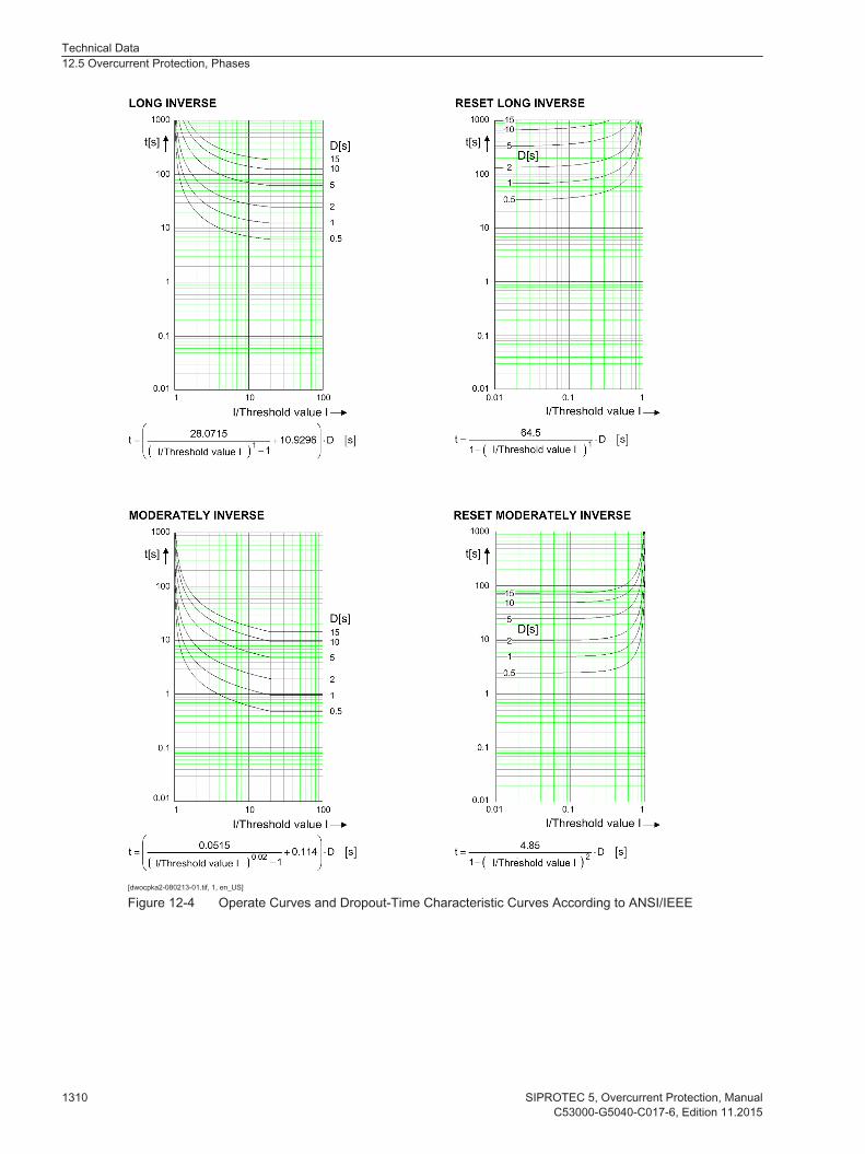
[dwocpka2-080213-01.tif, 1, en_US]
Figure 12-4 Operate Curves and Dropout-Time Characteristic Curves According to ANSI/IEEE
Technical Data12.5 Overcurrent Protection, Phases
1310 SIPROTEC 5, Overcurrent Protection, ManualC53000-G5040-C017-6, Edition 11.2015
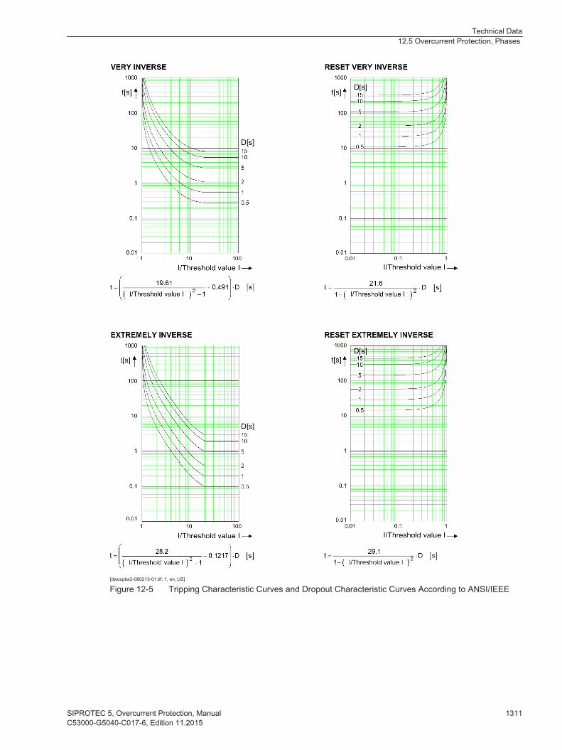
[dwocpka3-080213-01.tif, 1, en_US]
Figure 12-5 Tripping Characteristic Curves and Dropout Characteristic Curves According to ANSI/IEEE
Technical Data12.5 Overcurrent Protection, Phases
SIPROTEC 5, Overcurrent Protection, Manual 1311C53000-G5040-C017-6, Edition 11.2015
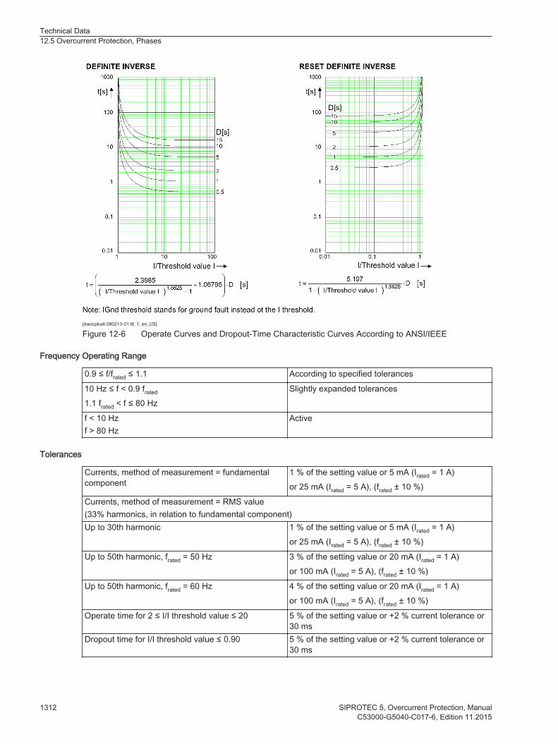
[dwocpka4-080213-01.tif, 1, en_US]
Figure 12-6 Operate Curves and Dropout-Time Characteristic Curves According to ANSI/IEEE
Frequency Operating Range
0.9 ≤ f/frated ≤ 1.1 According to specified tolerances
10 Hz ≤ f < 0.9 frated
1.1 frated < f ≤ 80 HzSlightly expanded tolerances
f < 10 Hzf > 80 Hz
Active
Tolerances
Currents, method of measurement = fundamentalcomponent
1 % of the setting value or 5 mA (Irated = 1 A)or 25 mA (Irated = 5 A), (frated ± 10 %)
Currents, method of measurement = RMS value(33% harmonics, in relation to fundamental component)Up to 30th harmonic 1 % of the setting value or 5 mA (Irated = 1 A)
or 25 mA (Irated = 5 A), (frated ± 10 %)
Up to 50th harmonic, frated = 50 Hz 3 % of the setting value or 20 mA (Irated = 1 A)or 100 mA (Irated = 5 A), (frated ± 10 %)
Up to 50th harmonic, frated = 60 Hz 4 % of the setting value or 20 mA (Irated = 1 A)or 100 mA (Irated = 5 A), (frated ± 10 %)
Operate time for 2 ≤ I/I threshold value ≤ 20 5 % of the setting value or +2 % current tolerance or30 ms
Dropout time for I/I threshold value ≤ 0.90 5 % of the setting value or +2 % current tolerance or30 ms
Technical Data12.5 Overcurrent Protection, Phases
1312 SIPROTEC 5, Overcurrent Protection, ManualC53000-G5040-C017-6, Edition 11.2015
Variables Influencing the Thresholds
Transient excess pickup in method of measurement = fundamental component,for τ > 100 ms (with complete unbalance)
< 5 %
Overcurrent Protection, Phases with User-Defined Characteristic Curve
Setting Values
Method of measurement Fundamental componentRMS value
–
Threshold value 1 A @ 50 and 100 Irated 0.030 A to 35.000 A Increments of 0.001 A5 A @ 50 and 100 Irated 0.15 A to 175.00 A Increments of 0.01 A1 A @ 1.6 Irated 0.001 A to 1.600 A Increments of 0.001 A5 A @ 1.6 Irated 0.005 A to 8.000 A Increments of 0.001 A
Dropout Disk emulationInstantaneous
–
Time multiplier 0.05 to 15.00 Increments of 0.01Number of value pairs for the operate curve 2 to 30 Increments of 1X values of the operate curve 1.00 to 66.67 p. u. Increments of 0.01 p.u.Y values of the operate curve 0.00 s to 999.00 s Increments of 0.01 sNumber of value pairs for the dropout characteristiccurve
2 to 30 Increments of 1
X values of the dropout characteristic curve 0.05 to 0.95 p. u. Increments of 0.01 p.u.Y values of the dropout characteristic curve 0.00 s to 999.00 s Increments of 0.01 s
Dropout Ratio
Disk emulation Approx. 0.90 * threshold valueInstantaneous Approx. 1.05 * threshold value
Approx. 0.95 * pickup value
Dropout
The greater dropout difference (= | pickup value – dropout value |) of the following 2 criteriaapplies:
Dropout difference derived from the parameter Dropout ratioIf this parameter is not available, a dropout ratio of 95 % applies for overcurrent and of 105 % for undercur-rent functionality.Minimum absolute dropout differenceProtection-class current transformer 15 mA sec. (Irated = 1 A) or
75 mA sec. (Irated = 5 A)
Instrument current transformer 0.5 mA sec. (Irated = 1 A) or2.5 mA sec. (Irated = 5 A)
Frequency Operating Range
0.9 ≤ f/frated ≤ 1.1 According to specified tolerances
10 Hz ≤ f < 0.9 frated
1.1 frated < f ≤ 80 HzSlightly expanded tolerances
12.5.3
Technical Data12.5 Overcurrent Protection, Phases
SIPROTEC 5, Overcurrent Protection, Manual 1313C53000-G5040-C017-6, Edition 11.2015
f < 10 Hzf > 80 Hz
Active
Tolerances
Currents, method of measurement = fundamentalcomponent
1 % of the setting value or 5 mA (Irated = 1 A)or 25 mA (Irated = 5 A), (frated ± 10 %)
Currents, method of measurement = RMS value(33 % harmonics, in relation to fundamental component)Up to 30th harmonic 1 % of the setting value or 5 mA (Irated = 1 A)
or 25 mA (Irated = 5 A), (frated ± 10 %)
Up to 50th harmonic, frated = 50 Hz 3 % of the setting value or 20 mA (Irated = 1 A)or 100 mA (Irated = 5 A), (frated ± 10 %)
Up to 50th harmonic, frated = 60 Hz 4 % of the setting value or 20 mA (Irated = 1 A)or 100 mA (Irated = 5 A), (frated ± 10 %)
Operate time for 2 ≤ I/I threshold value ≤ 20 5 % of the setting value or +2 % current tolerance or30 ms
Dropout time for I/I threshold value ≤ 0.90 5 % of the setting value or +2 % current tolerance or30 ms
Variables Influencing the Thresholds
Transient excess pickup in method of measurement = fundamental component,for τ > 100 ms (with complete unbalance)
< 5 %
Operate Curves and Dropout-Time Characteristic Curves according to IEC
Extension of the operate time during operation with transformer inrush-current detection
Approx. 10 ms
Technical Data12.5 Overcurrent Protection, Phases
1314 SIPROTEC 5, Overcurrent Protection, ManualC53000-G5040-C017-6, Edition 11.2015

Voltage-Dependent Overcurrent Protection, Phases
Setting Values for All Stage Types
Method of measurement Fundamental componentRMS value
–
Overcurrent thresholdvalue
For Irated = 1 A 0.030 A to 35.000 A Increments of 0.001 A
For Irated = 5 A 0.15 A to 175.00 A Increments of 0.01 A
Time delay 0.10 s to 60.00 s Increments of 0.01 s
Setting Values for Inverse-Time Overcurrent Stages
Method of measurement Fundamental componentRMS value
–
Dropout ratio of undervoltage37 1.01 to 1.20 Increments of 0.01Undervoltage threshold value37 0.300 V to 175.000 V Increments of 0.001 VDropout Disk emulation
instantaneous–
Time multiplier 0.05 to 15.00 Increments of 0.01
Setting Values for Definite-Time Overcurrent Stages
Seal-in voltage 0.300 V to 175.000 V Increments of 0.001 VPhase-to-phase voltage 0.300 V to 175.000 V Increments of 0.001 VNegative-sequence voltage V2 0.300 V to 200.000 V Increments of 0.001 VTime delay 0.00 s to 60.00 s Increments of 0.01 sDuration of V-seal-in time 0.10 s to 60.00 s Increments of 0.01 s
Dropout
The greater dropout difference (= | pickup value – dropout value |) of the following 2 criteriaapplies:
Dropout difference derived from the parameter Dropout ratioIf this parameter is not available, a dropout ratio of 95 % applies for overcurrent/overvoltage and of 105 %for undercurrent/undervoltage functionality.Minimum absolute dropout differenceProtection-class current transformer 15 mA sec. (Irated = 1 A) or
75 mA sec. (Irated = 5 A)
Instrument current transformer 0.5 mA sec. (Irated = 1 A) or2.5 mA sec. (Irated = 5 A)
Voltage transformer 150 mV sec.
Operate Curves and Dropout-Time Characteristic Curves According to IEC
Extension of the operate time during operation withinrush-current detection
Approx. 10 ms
The operate curves and dropout-time characteristic curves according to IEC can be found in the chapterTechnical Data under Inverse-Time Overcurrent Protection.
12.6
37 The setting value is for the inverse-time overcurrent voltage-released stage.
Technical Data12.6 Voltage-Dependent Overcurrent Protection, Phases
SIPROTEC 5, Overcurrent Protection, Manual 1315C53000-G5040-C017-6, Edition 11.2015

Operate Curves and Dropout-Time Characteristic Curves According to ANSI/IEEE
The operate curves and dropout-time characteristic curves according to IEC can be found in the chapterTechnical Data under Inverse-Time Overcurrent Protection.
Frequency Operating Range
0.9 f/frated to 1.1 f/frated According to specified tolerances
10 Hz to 0.9 f/frated
1.1 f/frated to 80 HzSlightly expanded tolerances
f < 10 Hzf > 80 Hz
Inactive
Tolerances
Currents, method of measurement = fundamentalcomponent
1 % of the setting value or 5 mA (Irated = 1 A) or 25mA (Irated = 5 A), (frated ± 10 %)
Currents, method of measurement = RMS value(33 % part of harmonic in relation to fundamentalcomponent)
Up to 30th harmonic1 % of the setting value or 5 mA (Irated = 1 A)or 25 mA (Irated = 5 A), (frated ± 10 %)
Up to 50th harmonic, frated = 50 Hz3 % of the setting value or 20 mA (Irated = 1 A)or 100 mA (Irated = 5 A), (frated ± 10 %)
Up to 50th harmonic, frated = 60 Hz4 % of the setting value or 20 mA (Irated = 1 A)or 100 mA (Irated = 5 A), (frated ± 10 %)
Voltage 0.5 % of the setting value or 0.05 VOperate time for 2 ≤ I/I threshold value ≤ 20 5 % of the setting value
or +2 % current tolerance or 30 msDropout time for I/I threshold value ≤ 0.90 5 % of the setting value
or +2 % current tolerance or 30 ms
Influencing Variables for Thresholds
Transient excess pickup in method of measurement = fundamental component, for τ >100 ms (with complete unbalance)
< 5 %
Technical Data12.6 Voltage-Dependent Overcurrent Protection, Phases
1316 SIPROTEC 5, Overcurrent Protection, ManualC53000-G5040-C017-6, Edition 11.2015

Overcurrent Protection, Ground
Definite-Time Overcurrent Protection, Ground
Setting Values
Method of measurement Fundamental componentRMS value
–
Threshold value38 1 A @ 50 and 100 Irated 0.030 A to 35.000 A Increments of 0.001 A5 A @ 50 and 100 Irated 0.15 A to 175.00 A Increments of 0.01 A1 A @ 1.6 Irated 0.001 A to 1.600 A Increments of 0.001 A5 A @ 1.6 Irated 0.005 A to 8.000 A Increments of 0.001 A
Dropout ratio 0.90 to 0.99 Increments of 0.01Time delay 0.00 s to 60.00 s Increments of 0.01 sDropout delay 0.00 s to 60.00 s Increments of 0.01 s
Dropout
The greater dropout difference (= | pickup value – dropout value |) of the following 2 criteriaapplies:
Dropout difference derived from the parameter Dropout ratioIf this parameter is not available, a dropout ratio of 95 % applies for overcurrent and of 105 % for undercur-rent functionality.Minimum absolute dropout differenceProtection-class current transformer 15 mA sec. (Irated = 1 A) or
75 mA sec. (Irated = 5 A)
Instrument current transformer 0.5 mA sec. (Irated = 1 A) or2.5 mA sec. (Irated = 5 A)
Times
Operate time with time delay = 0 ms Approx. 25 ms + OOT39 at 50 HzApprox. 22 ms + OOT at 60 Hz
Extension of the operate time during operation withtransformer inrush-current detection
Approx. 10 ms
Dropout time Approx. 20 ms + OOT
Frequency Operating Range
0.9 ≤ f/frated ≤ 1.1 According to specified tolerances
10 Hz ≤ f < 0.9 frated
1.1 frated < f ≤ 80 HzSlightly expanded tolerances
f < 10 Hzf > 80 Hz
Active
12.7
12.7.1
38 If you have selected the method of measurement = RMS value, do not set the threshold value under 0.1 lrated,sec.39 OOT (Output Operating Time) additional delay of the output medium used, see Chapter 12.1.4 Relay Outputs
Technical Data12.7 Overcurrent Protection, Ground
SIPROTEC 5, Overcurrent Protection, Manual 1317C53000-G5040-C017-6, Edition 11.2015

Tolerances
3I0 measured via I440, method of measurement =fundamental component
1 % of the setting value or 5 mA (Irated = 1 A)or 25 mA (Irated = 5 A), (frated ± 10 %)
3I0 measured via I441, method of measurement = RMS value(33 % harmonics, in relation to fundamental component)Up to 30th harmonic 1 % of the setting value or 5 mA (Irated = 1 A)
or 25 mA (Irated = 5 A), (frated ± 10 %)
Up to 50th harmonic, frated = 50 Hz 3 % of the setting value or 20 mA (Irated = 1 A)or 100 mA (Irated = 5 A), (frated ± 10 %)
Up to 50th harmonic, frated = 60 Hz 4 % of the setting value or 20 mA (Irated = 1 A)or 100 mA (Irated = 5 A), (frated ± 10 %)
Time delays 1 % of the setting value or 10 ms
Influencing Variables for Thresholds
Transient excess pickup in method of measurement = fundamental component,for τ > 100 ms (with complete unbalance)
< 5 %
Inverse-Time Overcurrent Protection, Ground
Setting Values
Method of measurement Fundamental componentRMS value
–
Threshold value42 1 A @ 50 and 100 Irated 0.030 A to 35.000 A Increments of 0.001 A5 A @ 50 and 100 Irated 0.15 A to 175.00 A Increments of 0.01 A1 A @ 1.6 Irated 0.001 A to 1.600 A Increments of 0.001 A5 A @ 1.6 Irated 0.005 A to 8.000 A Increments of 0.001 A
Dropout Disk emulationInstantaneous
–
Time multiplier 0.00 to 15.00 Increments of 0.01Minimum time of the curve 0.00 to 1.00 s Increments of 0.01 sAdditional time delay 0.00 to 60.00 s Increments of 0.01 s
Dropout Ratio
Disk emulation Approx. 0.90 * threshold valueInstantaneous Approx. 1.05 * threshold value
Approx. 0.95 * pickup value
Dropout
The greater dropout difference (= | pickup value – dropout value |) of the following 2 criteriaapplies:
12.7.2
40 Slightly expanded tolerances will occur during the calculation of 3I0, maximum factor of 241 Slightly expanded tolerances will occur during the calculation of 3I0, maximum factor of 242 If you have selected the method of measurement = RMS value, do not set the threshold value under 0.1 lrated,sec.
Technical Data12.7 Overcurrent Protection, Ground
1318 SIPROTEC 5, Overcurrent Protection, ManualC53000-G5040-C017-6, Edition 11.2015
Dropout difference derived from the parameter Dropout ratioIf this parameter is not available, a dropout ratio of 95 % applies for overcurrent and of 105 % for undercur-rent functionality.Minimum absolute dropout differenceProtection-class current transformer 15 mA sec. (Irated = 1 A) or
75 mA sec. (Irated = 5 A)
Instrument current transformer 0.5 mA sec. (Irated = 1 A) or2.5 mA sec. (Irated = 5 A)
Operate Curves and Dropout-Time Characteristic Curves According to IEC
Extension of the operate time during operation with transformer inrush-current detection
Approx. 10 ms
Technical Data12.7 Overcurrent Protection, Ground
SIPROTEC 5, Overcurrent Protection, Manual 1319C53000-G5040-C017-6, Edition 11.2015

[dwocpki1-080213-01.tif, 1, en_US]
Figure 12-7 Operate Curves and Dropout-Time Characteristic Curves According to IEC
Technical Data12.7 Overcurrent Protection, Ground
1320 SIPROTEC 5, Overcurrent Protection, ManualC53000-G5040-C017-6, Edition 11.2015

[dwocpki2-080213-01.tif, 1, en_US]
Figure 12-8 Operate Curves and Dropout-Time Characteristic Curves According to IEC
Technical Data12.7 Overcurrent Protection, Ground
SIPROTEC 5, Overcurrent Protection, Manual 1321C53000-G5040-C017-6, Edition 11.2015

Operate Curves and Dropout-Time Characteristic Curves According to ANSI/IEEE
[dwocpka1-080213-01.tif, 1, en_US]
Figure 12-9 Operate Curves and Dropout-Time Characteristic Curves According to ANSI/IEEE
Technical Data12.7 Overcurrent Protection, Ground
1322 SIPROTEC 5, Overcurrent Protection, ManualC53000-G5040-C017-6, Edition 11.2015
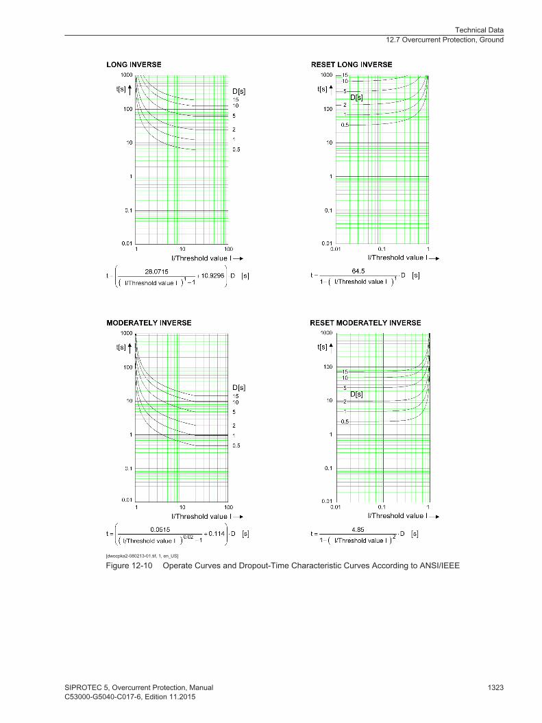
[dwocpka2-080213-01.tif, 1, en_US]
Figure 12-10 Operate Curves and Dropout-Time Characteristic Curves According to ANSI/IEEE
Technical Data12.7 Overcurrent Protection, Ground
SIPROTEC 5, Overcurrent Protection, Manual 1323C53000-G5040-C017-6, Edition 11.2015

[dwocpka3-080213-01.tif, 1, en_US]
Figure 12-11 Operate Curves and Dropout-Time Characteristic Curves According to ANSI/IEEE
Technical Data12.7 Overcurrent Protection, Ground
1324 SIPROTEC 5, Overcurrent Protection, ManualC53000-G5040-C017-6, Edition 11.2015

[dwocpka4-080213-01.tif, 1, en_US]
Figure 12-12 Operate Curves and Dropout-Time Characteristic Curves According to ANSI/IEEE
Frequency Operating Range
0.9 ≤ f/frated ≤ 1.1 According to specified tolerances
10 Hz ≤ f < 0.9 frated
1.1 frated < f ≤ 80 HzSlightly expanded tolerances
f < 10 Hzf > 80 Hz
Active
Tolerances
3I0 measured via I443, method of measurement =fundamental component
1 % of the setting value or 5 mA (Irated = 1 A)or 25 mA (Irated = 5 A), (frated ± 10 %)
3I0 measured via I444, method of measurement = RMS value(33 % harmonics, in relation to fundamental component)Up to 30th harmonic 1 % of the setting value or 5 mA (Irated = 1 A)
or 25 mA (Irated = 5 A), (frated ± 10 %)
Up to 50th harmonic, frated = 50 Hz 3 % of the setting value or 20 mA (Irated = 1 A)or 100 mA (Irated = 5 A), (frated ± 10 %)
Up to 50th harmonic, frated = 60 Hz 4 % of the setting value or 20 mA (Irated = 1 A)or 100 mA (Irated = 5 A), (frated ± 10 %)
Operate time for 2 ≤ I/I threshold value ≤ 20 5 % of the setting value or +2 % current tolerance or30 ms
43 Insignificantly increased tolerances will occur during the calculation of 3I0, maximum factor of 244 Insignificantly increased tolerances will occur during the calculation of 3I0, maximum factor of 2
Technical Data12.7 Overcurrent Protection, Ground
SIPROTEC 5, Overcurrent Protection, Manual 1325C53000-G5040-C017-6, Edition 11.2015
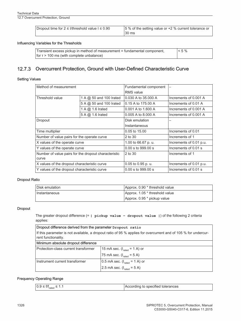
Dropout time for 2 ≤ I/threshold value I ≤ 0.90 5 % of the setting value or +2 % current tolerance or30 ms
Influencing Variables for the Thresholds
Transient excess pickup in method of measurement = fundamental component,for τ > 100 ms (with complete unbalance)
< 5 %
Overcurrent Protection, Ground with User-Defined Characteristic Curve
Setting Values
Method of measurement Fundamental componentRMS value
–
Threshold value 1 A @ 50 and 100 Irated 0.030 A to 35.000 A Increments of 0.001 A5 A @ 50 and 100 Irated 0.15 A to 175.00 A Increments of 0.01 A1 A @ 1.6 Irated 0.001 A to 1.600 A Increments of 0.001 A5 A @ 1.6 Irated 0.005 A to 8.000 A Increments of 0.001 A
Dropout Disk emulationInstantaneous
–
Time multiplier 0.05 to 15.00 Increments of 0.01Number of value pairs for the operate curve 2 to 30 Increments of 1X values of the operate curve 1.00 to 66.67 p. u. Increments of 0.01 p.u.Y values of the operate curve 0.00 s to 999.00 s Increments of 0.01 sNumber of value pairs for the dropout characteristiccurve
2 to 30 Increments of 1
X values of the dropout characteristic curve 0.05 to 0.95 p. u. Increments of 0.01 p.u.Y values of the dropout characteristic curve 0.00 s to 999.00 s Increments of 0.01 s
Dropout Ratio
Disk emulation Approx. 0.90 * threshold valueInstantaneous Approx. 1.05 * threshold value
Approx. 0.95 * pickup value
Dropout
The greater dropout difference (= | pickup value – dropout value |) of the following 2 criteriaapplies:
Dropout difference derived from the parameter Dropout ratioIf this parameter is not available, a dropout ratio of 95 % applies for overcurrent and of 105 % for undercur-rent functionality.Minimum absolute dropout differenceProtection-class current transformer 15 mA sec. (Irated = 1 A) or
75 mA sec. (Irated = 5 A)
Instrument current transformer 0.5 mA sec. (Irated = 1 A) or2.5 mA sec. (Irated = 5 A)
Frequency Operating Range
0.9 ≤ f/frated ≤ 1.1 According to specified tolerances
12.7.3
Technical Data12.7 Overcurrent Protection, Ground
1326 SIPROTEC 5, Overcurrent Protection, ManualC53000-G5040-C017-6, Edition 11.2015

10 Hz ≤ f < 0.9 frated
1.1 frated < f ≤ 80 HzSlightly expanded tolerances
f < 10 Hzf > 80 Hz
Active
Tolerances
3I0 measured via I445, method of measurement =fundamental component
1 % of the setting value or 5 mA (Irated = 1 A)or 25 mA (Irated = 5 A), (frated ± 10 %)
3I0 measured via I446, method of measurement = RMS value(33 % harmonics, in relation to fundamental component)Up to 30th harmonic 1 % of the setting value or 5 mA (Irated = 1 A)
or 25 mA (Irated = 5 A), (frated ± 10 %)
Up to 50th harmonic, frated = 50 Hz 3 % of the setting value or 20 mA (Irated = 1 A)or 100 mA (Irated = 5 A), (frated ± 10 %)
Up to 50th harmonic, frated = 60 Hz 4 % of the setting value or 20 mA (Irated = 1 A)or 100 mA (Irated = 5 A), (frated ± 10 %)
Operate time for 2 ≤ I/I threshold value ≤ 20 5 % of the setting value or +2 % current tolerance or30 ms
Dropout time for I/I threshold value ≤ 0.90 5 % of the setting value or +2 % current tolerance or30 ms
Influencing Variables for the Thresholds
Transient excess pickup in method of measurement= fundamental component, for τ > 100 ms (withcomplete unbalance)
< 5 %
Operate Curves and Dropout-Time Characteristic Curves According to IEC
Extension of the operate time during operation withtransformer inrush-current detection
Approx. 10 ms
45 Insignificantly increased tolerances will occur during the calculation of 3I0, maximum factor of 246 Insignificantly increased tolerances will occur during the calculation of 3I0, maximum factor of 2
Technical Data12.7 Overcurrent Protection, Ground
SIPROTEC 5, Overcurrent Protection, Manual 1327C53000-G5040-C017-6, Edition 11.2015
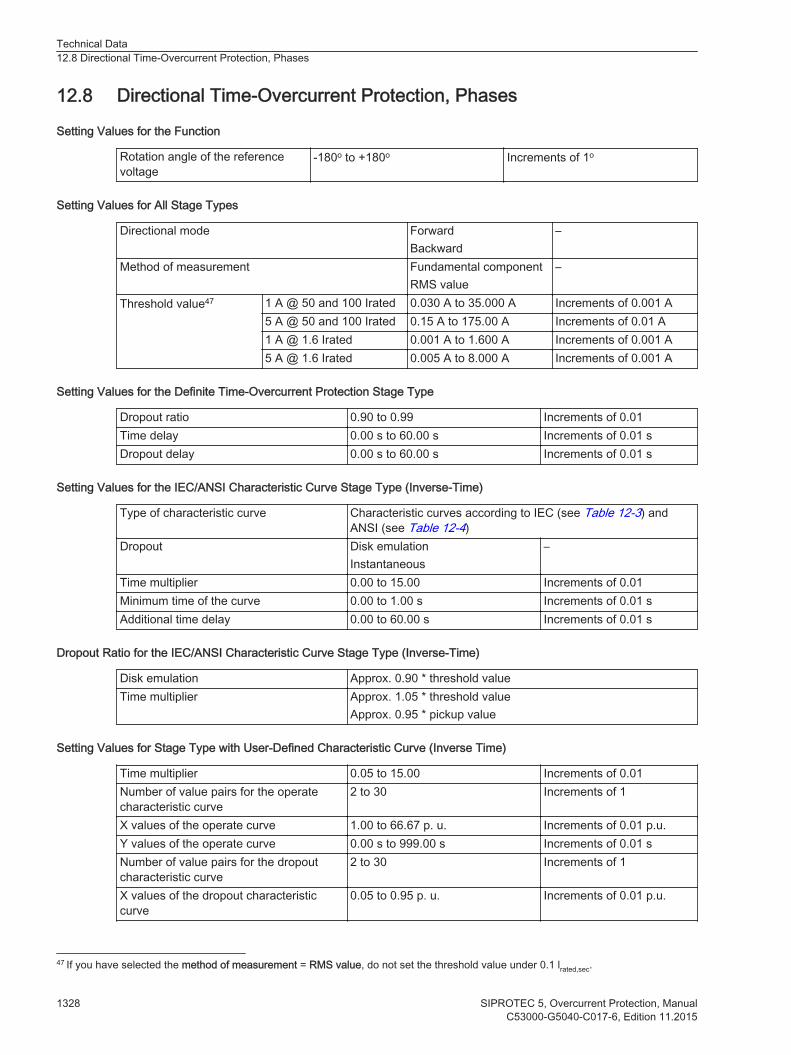
Directional Time-Overcurrent Protection, Phases
Setting Values for the Function
Rotation angle of the referencevoltage
-180o to +180o Increments of 1o
Setting Values for All Stage Types
Directional mode ForwardBackward
–
Method of measurement Fundamental componentRMS value
–
Threshold value47 1 A @ 50 and 100 Irated 0.030 A to 35.000 A Increments of 0.001 A5 A @ 50 and 100 Irated 0.15 A to 175.00 A Increments of 0.01 A1 A @ 1.6 Irated 0.001 A to 1.600 A Increments of 0.001 A5 A @ 1.6 Irated 0.005 A to 8.000 A Increments of 0.001 A
Setting Values for the Definite Time-Overcurrent Protection Stage Type
Dropout ratio 0.90 to 0.99 Increments of 0.01Time delay 0.00 s to 60.00 s Increments of 0.01 sDropout delay 0.00 s to 60.00 s Increments of 0.01 s
Setting Values for the IEC/ANSI Characteristic Curve Stage Type (Inverse-Time)
Type of characteristic curve Characteristic curves according to IEC (see Table 12-3) andANSI (see Table 12-4)
Dropout Disk emulationInstantaneous
–
Time multiplier 0.00 to 15.00 Increments of 0.01Minimum time of the curve 0.00 to 1.00 s Increments of 0.01 sAdditional time delay 0.00 to 60.00 s Increments of 0.01 s
Dropout Ratio for the IEC/ANSI Characteristic Curve Stage Type (Inverse-Time)
Disk emulation Approx. 0.90 * threshold valueTime multiplier Approx. 1.05 * threshold value
Approx. 0.95 * pickup value
Setting Values for Stage Type with User-Defined Characteristic Curve (Inverse Time)
Time multiplier 0.05 to 15.00 Increments of 0.01Number of value pairs for the operatecharacteristic curve
2 to 30 Increments of 1
X values of the operate curve 1.00 to 66.67 p. u. Increments of 0.01 p.u.Y values of the operate curve 0.00 s to 999.00 s Increments of 0.01 sNumber of value pairs for the dropoutcharacteristic curve
2 to 30 Increments of 1
X values of the dropout characteristiccurve
0.05 to 0.95 p. u. Increments of 0.01 p.u.
12.8
47 If you have selected the method of measurement = RMS value, do not set the threshold value under 0.1 lrated,sec.
Technical Data12.8 Directional Time-Overcurrent Protection, Phases
1328 SIPROTEC 5, Overcurrent Protection, ManualC53000-G5040-C017-6, Edition 11.2015

Y values of the dropout characteristiccurve
0.00 s to 999.00 s Increments of 0.01 s
Dropout Ratio for Stage Type with User-Defined Characteristic Curve (Inverse Time)
Disk emulation Approx. 0.90 * threshold valueTime multiplier Approx. 1.05 * threshold value
Approx. 0.95 * pickup value
Tripping and Dropout Characteristic Curves
You can select from the following tripping and dropout characteristic curves:
Table 12-3 Standard characteristic curves to IEC
Normal inverse: type A See chapter 12.5.2 Inverse Time-Overcurrent Protec-tion, Phases , Figure 12-1Very inverse: type B
Extremely inverse: type C See chapter 12.5.2 Inverse Time-Overcurrent Protec-tion, Phases , Figure 12-2Long time inverse:
Table 12-4 Standard characteristic curves to ANSI/IEEE
Inverse: type C See chapter 12.5.2 Inverse Time-Overcurrent Protec-tion, Phases , Figure 12-3Short inverse
Long inverse See chapter 12.5.2 Inverse Time-Overcurrent Protec-tion, Phases , Figure 12-4Moderately inverse
Very inverse See chapter 12.5.2 Inverse Time-Overcurrent Protec-tion, Phases , Figure 12-5Extremely inverse
Definite inverse See chapter 12.5.2 Inverse Time-Overcurrent Protec-tion, Phases , Figure 12-6
Direction Determination
Type With externally generated voltagesWith voltage memory 2 s
Forward range Vref,rot ±88o
Dropout differential forward/reverse range 1o
Directional sensitivity Unlimited for 1 and 2-phase short circuitsDynamically unlimited, stationary for 3-phase shortcircuitsApprox. 13 V phase-to-phase
Dropout
The greater dropout difference (= | pickup value – dropout value |) of the following 2 criteriaapplies:
Dropout difference derived from the parameter Dropout ratioIf this parameter is not available, a dropout ratio of 95 % applies for overcurrent and of 105 % for undercur-rent functionality.Minimum absolute dropout differenceProtection-class current transformer 15 mA sec. (Irated = 1 A) or
75 mA sec. (Irated = 5 A)
Technical Data12.8 Directional Time-Overcurrent Protection, Phases
SIPROTEC 5, Overcurrent Protection, Manual 1329C53000-G5040-C017-6, Edition 11.2015

Instrument current transformer 0.5 mA sec. (Irated = 1 A) or2.5 mA sec. (Irated = 5 A)
Times
Operate time with time delay = 0 ms Approx. 37 ms + OOT 48 at 50 HzApprox. 22 ms + OOT at 60 Hz
Extension of the operate time during operation withtransformer inrush-current detection
Approx. 10 ms
Dropout Time Approx. 20 ms + OOT
Frequency Operating Range
0.9 ≤ f/frated ≤ 1.1 According to specified tolerances
10 Hz ≤ f < 0.9frated
1.1 frated < f ≤ 80 HzSlightly expanded tolerances
f < 10 Hzf > 80 Hz
Active
Tolerances
Currents, method of measurement = fundamentalcomponent
1 % of the setting value or 5 mA (Irated = 1 A)or 25 mA (Irated = 5 A), (frated ± 10 %)
Currents, method of measurement = RMS value(33 % harmonics, in relation to fundamental component)Up to 30th harmonic 1 % of the setting value or 5 mA (Irated = 1 A)
or 25 mA (Irated = 5 A), (frated ± 10 %)
Up to 50th harmonic, frated = 50 Hz 3 % of the setting value or 20 mA (Irated = 1 A)or 100 mA (Irated = 5 A), (frated ± 10 %)
Up to 50th harmonic, frated = 60 Hz 4 % of the setting value or 20 mA (Irated = 1 A)or 100 mA (Irated = 5 A), (frated ± 10 %)
Definite-time operate time 1 % of the setting value or 10 msInverse-time operate time according to IEC, ANSI,user-defined characteristic curve
5 % of the setting value or +2 % current tolerance or10 ms
Inverse-time dropout time according to IEC, ANSI,user-defined characteristic curve
5 % of the setting value or +2 % current tolerance or10 ms
Direction-determination angle error 1o
Influencing Variables for Thresholds
Transient excess pickup in method of measurement = fundamental component,for τ > 100 ms (with complete unbalance)
< 5 %
48 OOT (Output Operating Time) additional delay of the output medium used, for example 5 ms with fast relays
Technical Data12.8 Directional Time-Overcurrent Protection, Phases
1330 SIPROTEC 5, Overcurrent Protection, ManualC53000-G5040-C017-6, Edition 11.2015

Directional Time-Overcurrent Protection, Ground
Setting Values for the Function Direction Determination
Method for direction determination Zero sequenceNegative sequence
–
Minimum V0 or V2 threshold 0.150 V to 20.000 V 0.001 VRotation angle of the reference voltage -180° to 180° 1°Forward range 0° to 180° 1°
Setting Values for All Stage Types
Direction mode ForwardReverse
–
Method of measurement Fundamental componentRMS value
–
Threshold value 1 A @ 50 and 100 Irated 0.030 A to 35.000 A Increments of 0.001 A5 A @ 50 and 100 Irated 0.15 A to 175.00 A Increments of 0.01 A1 A @ 1.6 Irated 0.030 A to 1.600 A Increments of 0.001 A5 A @ 1.6 Irated 0.15 A to 8.000 A Increments of 0.001 A
Setting Values for Stage Type Definite Time-Overcurrent Protection
Dropout ratio 0.90 to 0.99 Increments of 0.01Operate delay 0.00 s to 60.00 s Increments of 0.01 sDropout delay 0.00 s to 60.00 s Increments of 0.01 s
Setting Values for Stage Type Inverse Time-Overcurrent Protection (IEC/ANSI)
Type of characteristic curve Characteristic curves according to IEC and ANSIDropout Disk emulation
Instantaneous–
Time multiplier 0.00 to 15.00 Increments of 0.01Minimum time of the curve 0.00 to 1.00 s Increments of 0.01 sAdditional time delay 0.00 to 60.00 s Increments of 0.01 s
Dropout Values for Stage Type Inverse Time-Overcurrent Protection (IEC/ANSI)
Disk emulation Approx. 0.90 * threshold valueInstantaneous Approx. 1.05 * threshold value
Approx. 0.95 * pickup value
Characteristic Curves for Stage Type Inverse Time-Overcurrent Protection (IEC/ANSI)
Standard Characteristic Curves According to IEC
Normal inverse: type A Refer to the respective picture of the technical data for the non-dir-OC-ground function 12.7.2 Inverse-Time Overcurrent Protec-tion, Ground
Very inverse: type BExtremely inverse: type CLong-time inverse
Standard Characteristic Curves According to ANSI/IEEE
12.9
Technical Data12.9 Directional Time-Overcurrent Protection, Ground
SIPROTEC 5, Overcurrent Protection, Manual 1331C53000-G5040-C017-6, Edition 11.2015
Extremely inverse: type C Refer to the respective picture of the technical data for the non-dir-OC-ground function 12.7.2 Inverse-Time Overcurrent Protec-tion, Ground
Long-time inverse: type BLong-time inverseModerately inverseVery inverseExtremely inverseUniformly inverse
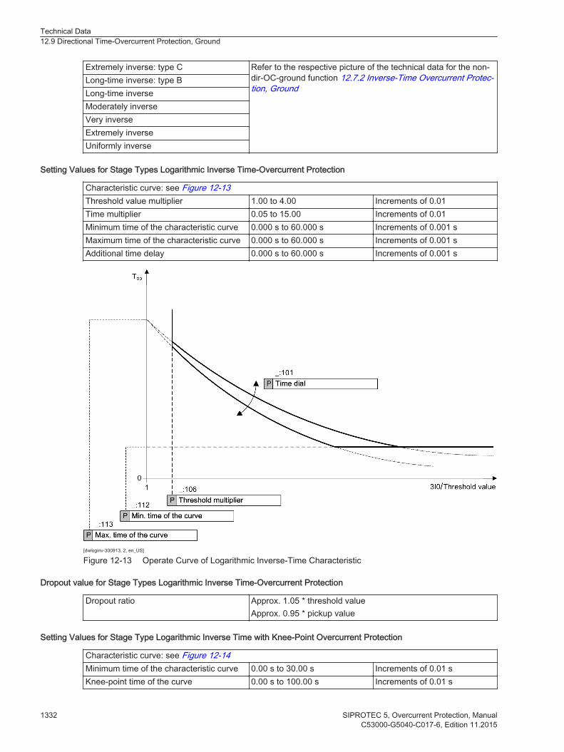
Setting Values for Stage Types Logarithmic Inverse Time-Overcurrent Protection
Characteristic curve: see Figure 12-13Threshold value multiplier 1.00 to 4.00 Increments of 0.01Time multiplier 0.05 to 15.00 Increments of 0.01Minimum time of the characteristic curve 0.000 s to 60.000 s Increments of 0.001 sMaximum time of the characteristic curve 0.000 s to 60.000 s Increments of 0.001 sAdditional time delay 0.000 s to 60.000 s Increments of 0.001 s
[dwloginv-300913, 2, en_US]
Figure 12-13 Operate Curve of Logarithmic Inverse-Time Characteristic
Dropout value for Stage Types Logarithmic Inverse Time-Overcurrent Protection
Dropout ratio Approx. 1.05 * threshold valueApprox. 0.95 * pickup value
Setting Values for Stage Type Logarithmic Inverse Time with Knee-Point Overcurrent Protection
Characteristic curve: see Figure 12-14Minimum time of the characteristic curve 0.00 s to 30.00 s Increments of 0.01 sKnee-point time of the curve 0.00 s to 100.00 s Increments of 0.01 s
Technical Data12.9 Directional Time-Overcurrent Protection, Ground
1332 SIPROTEC 5, Overcurrent Protection, ManualC53000-G5040-C017-6, Edition 11.2015
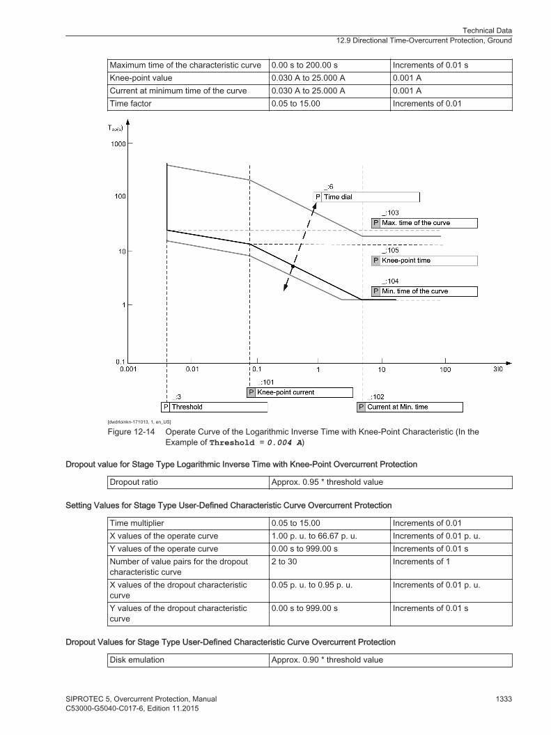
Maximum time of the characteristic curve 0.00 s to 200.00 s Increments of 0.01 sKnee-point value 0.030 A to 25.000 A 0.001 ACurrent at minimum time of the curve 0.030 A to 25.000 A 0.001 ATime factor 0.05 to 15.00 Increments of 0.01
[dwdrloinkn-171013, 1, en_US]
Figure 12-14 Operate Curve of the Logarithmic Inverse Time with Knee-Point Characteristic (In theExample of Threshold = 0.004 A)
Dropout value for Stage Type Logarithmic Inverse Time with Knee-Point Overcurrent Protection
Dropout ratio Approx. 0.95 * threshold value
Setting Values for Stage Type User-Defined Characteristic Curve Overcurrent Protection
Time multiplier 0.05 to 15.00 Increments of 0.01X values of the operate curve 1.00 p. u. to 66.67 p. u. Increments of 0.01 p. u.Y values of the operate curve 0.00 s to 999.00 s Increments of 0.01 sNumber of value pairs for the dropoutcharacteristic curve
2 to 30 Increments of 1
X values of the dropout characteristiccurve
0.05 p. u. to 0.95 p. u. Increments of 0.01 p. u.
Y values of the dropout characteristiccurve
0.00 s to 999.00 s Increments of 0.01 s
Dropout Values for Stage Type User-Defined Characteristic Curve Overcurrent Protection
Disk emulation Approx. 0.90 * threshold value
Technical Data12.9 Directional Time-Overcurrent Protection, Ground
SIPROTEC 5, Overcurrent Protection, Manual 1333C53000-G5040-C017-6, Edition 11.2015

Instantaneous Approx. 1.05 * threshold valueApprox. 0.95 * pickup value
Dropout
The greater dropout difference (= | pickup value – dropout value |) of the following 2 criteriaapplies:
Dropout difference derived from the parameter Dropout ratioIf this parameter is not available, a dropout ratio of 95 % applies for overcurrent and of 105 % for undercur-rent functionality.Minimum absolute dropout differenceProtection-class current transformer 15 mA sec. (Irated = 1 A) or
75 mA sec. (Irated = 5 A)
Instrument current transformer 0.5 mA sec. (Irated = 1 A) or2.5 mA sec. (Irated = 5 A)
Times
The maximum pickup time with operatedelay = 0 ms
Approx. 30 ms + OOT at 50 HzApprox. 25 ms + OOT at 60 Hz
Extension of the operate time during oper-ation with inrush-current detection
Approx. 10 ms
Dropout time Approx. 20 ms + OOT
Frequency Operating Range
0.9 ≤ f/frated ≤ 1.1 According to specified tolerances
10 Hz ≤ f < 0.9 frated
1.1 frated < f ≤ 80 HzSlightly expanded tolerances
f < 10 Hzf > 80 Hz
Active with reduced sensitivity
Tolerances
Currents, method of measurement = fundamentalcomponent
1 % of setting value or 5 mA (Irated = 1 A) or 25 mA(Irated = 5 A)
Currents, method of measurement = RMS value(33 % part of harmonic, referring to fundamental compo-nent)
Up to 30th harmonic1 % of setting value or 5 mA (Irated = 1 A)or 25 mA (Irated = 5 A), (frated ± 10 %)
Up to 50th harmonic, frated = 50 Hz3 % of setting value or 20 mA (Irated = 1 A)or 100 mA (Irated = 5 A), (frated ± 10 %)
Up to 50th harmonic, frated = 60 Hz4 % of setting value or 20 mA (Irated = 1 A)or 100 mA (Irated = 5 A), (frated ± 10 %)
Definite-time operate time 1 % of the setting or 10 msInverse-time operate time to IEC, ANSI, logarithmicinverse-time characteristic, logarithmic inverse time withknee-point characteristic, and user-defined character-istic curve
5 % of setting value or +2 % current tolerance or30 ms
Technical Data12.9 Directional Time-Overcurrent Protection, Ground
1334 SIPROTEC 5, Overcurrent Protection, ManualC53000-G5040-C017-6, Edition 11.2015

Inverse-time dropout time to IEC, ANSI, logarithmicinverse-time characteristic, logarithmic inverse time withknee-point characteristic, and user-defined character-istic curve
5 % of setting value or +2 % current tolerance or30 ms
Direction-determination angle error 1º
Influencing Variables for Thresholds
Transient excess pickup in method of measurement =fundamental component, for τ > 100 ms (with completeunbalance)
< 5 %
Technical Data12.9 Directional Time-Overcurrent Protection, Ground
SIPROTEC 5, Overcurrent Protection, Manual 1335C53000-G5040-C017-6, Edition 11.2015

Inrush-Current Detection
Setting Values
Operat.-range limit Imax 1 A @ 50 and 100 Irated 0.030 A to 35.000 A Increments of 0.001 A5 A @ 50 and 100 Irated 0.15 A to 175.00 A Increments of 0.01 A1 A @ 1.6 Irated 0.001 A to 1.600 A Increments of 0.001 A5 A @ 1.6 Irated 0.005 A to 8.000 A Increments of 0.001 A
Content 2nd harmonic 10 % to 45 % Increments of 1 %Duration of the cross-blocking 0.03 s to 200.00 s Increments of 0.01 s
Times
Pickup times Approx. 29 ms
Dropout Ratios
Harmonic: I2nd Harm/I1st harm 0.95
Dropout
The greater dropout difference (= | pickup value – dropout value |) of the following 2 criteriaapplies:
Dropout difference derived from the parameter Dropout ratioIf this parameter is not available, a dropout ratio of 95 % applies for overcurrent and of 105 % for undercur-rent functionality.Dropout differenceProtection-class current transformer 15 mA sec. (Irated = 1 A) or
75 mA sec. (Irated = 5 A)
Instrument current transformer 0.5 mA sec. (Irated = 1 A) or2.5 mA sec. (Irated = 5 A)
Operating Range
10 Hz to 80 Hz According to specified tolerancesBehavior outside 10 Hz to 80 Hz Inactive
Tolerances
Current measurement lmax 1 % of the setting value or 5 mA
Harmonic: I2nd Harm/I1st Harm 1 % of the setting valuefor settings of l2nd Harm/1st Harm
Time delays 1 % of the setting value or 10 ms
12.10
Technical Data12.10 Inrush-Current Detection
1336 SIPROTEC 5, Overcurrent Protection, ManualC53000-G5040-C017-6, Edition 11.2015
Arc Protection
Setting Values
Threshold value I> 1 A @ 50 and 100 Irated 0.030 A to 35.000 A Increments of 0.001 A5 A @ 50 and 100 Irated 0.15 A to 175.00 A Increments of 0.01 A1 A @ 1.6 Irated 0.001 A to 1.600 A Increments of 0.001 A5 A @ 1.6 Irated 0.005 A to 8.000 A Increments of 0.001 A
Threshold value 3I0> 1 A @ 50 and 100 Irated 0.030 A to 35.000 A Increments of 0.001 A5 A @ 50 and 100 Irated 0.15 A to 175.00 A Increments of 0.01 A1 A @ 1.6 Irated 0.001 A to 1.600 A Increments of 0.001 A5 A @ 1.6 Irated 0.005 A to 8.000 A Increments of 0.001 A
External trip initiation YesNo
Operating mode Light onlyCurrent and light
Channel Possible settings, application-dependent
Dropout Ratio
Threshold value About 0.90
Times
Shortest operate timeOperating mode = light only
Approx. 2.6 ms + OOT 49.
Shortest operate timeOperating mode = Current andlight
Approx. 4.0 ms + OOT at 50 HzApprox. 3.8 ms + OOT at 60 Hz
12.11
49 OOT (Output Operating Time) additional delay of the output medium used, for example 5 ms with fast relays, see chapter12.1.4 Relay Outputs
Technical Data12.11 Arc Protection
SIPROTEC 5, Overcurrent Protection, Manual 1337C53000-G5040-C017-6, Edition 11.2015

Instantaneous High-Current Tripping
Setting Values
Threshold value 1 A @ 100 Irated 0.030 A to 35.000 A Increments of 0.001 A5 A @ 100 Irated 0.15 A to 175.00 A Increments of 0.01 A1 A @ 50 Irated 0.030 A to 35.000 A Increments of 0.001 A5 A @ 50 Irated 0.15 A to 175.00 A Increments of 0.01 A1 A @ 1.6 Irated 0.001 A to 1.600 A Increments of 0.001 A5 A @ 1.6 Irated 0.005 A to 8.000 A Increments of 0.001 A
Dropout Ratio 0.50 to 0.90 Increments of 0.01
Dropout
The greater dropout difference (= | pickup value – dropout value |) of the following 2 criteriaapplies:
Dropout difference derived from the parameter Dropout ratioIf this parameter is not available, a dropout ratio of 95 % applies for overcurrent and of 105 % for undercur-rent functionality.Minimum absolute dropout differenceProtection-class current transformer 15 mA sec. (Irated = 1 A) or
75 mA sec. (Irated = 5 A)
Instrument current transformer 0.5 mA sec. (Irated = 1 A) or2.5 mA sec. (Irated = 5 A)
Times
Operate time for current > 2·√2·threshold value Approx. 8 ms + OOT50
Operating Range
frated ± 10 % According to specified tolerances
Behavior outside the operating range Active starting at f ≥ 36.3 Hz
Tolerances
Response tolerance, current 5 % of setting value or 10 mA at Irated = 1 A5 % of setting value or 50 mA at Irated = 5 A
Time delays 1 % of the setting value or 10 ms
12.12
50 OOT (Output Operating Time) additional delay of the output medium used, see chapter 12.1.4 Relay Outputs
Technical Data12.12 Instantaneous High-Current Tripping
1338 SIPROTEC 5, Overcurrent Protection, ManualC53000-G5040-C017-6, Edition 11.2015

Instantaneous Tripping at Switch onto Fault
Setting Values
Tripping delay 0.00 s to 60.00 s Increments of0.01 s
Tolerances
Times < 1 % of the setting value or 10 ms
12.13
Technical Data12.13 Instantaneous Tripping at Switch onto Fault
SIPROTEC 5, Overcurrent Protection, Manual 1339C53000-G5040-C017-6, Edition 11.2015
Overcurrent Protection, 1-Phase
Overcurrent Protection, 1-Phase (Stage with Definite Time-OvercurrentProtection)
Setting Values
Method of measurement Fundamental componentRMS value
–
Threshold value51 1 A @ 50 and 100 Irated 0.030 A to 35.000 A Increments of 0.001 A5 A @ 50 and 100 Irated 0.15 A to 175.00 A Increments of 0.01 A1 A @ 1.6 Irated 0.001 A to 1.600 A Increments of 0.001 A5 A @ 1.6 Irated 0.005 A to 8.000 A Increments of 0.001 A
Dropout ratio (fixed) 0.95 –Time delay 0.00 s to 60.00 s Increments of 0.01 s
Dropout
The greater dropout difference (= | pickup value – dropout value |) of the following 2 criteriaapplies:
Dropout difference derived from the parameter Dropout ratioIf this parameter is not available, a dropout ratio of 95 % applies for overcurrent and of 105 % for undercur-rent functionality.Minimum absolute dropout differenceProtection-class current transformer 15 mA sec. (Irated = 1 A) or
75 mA sec. (Irated = 5 A)
Instrument current transformer 0.5 mA sec. (Irated = 1 A) or2.5 mA sec. (Irated = 5 A)
Times
Operate time with time delay = 0 ms Approx. 15 ms + OOT52 at 50 HzApprox. 14 ms + OOT at 60 Hz
Extension of the operate time during operation withtransformer inrush-current detection
Approx. 10 ms
Dropout time Approx. 20 ms + OOT at 50 HzApprox. 17 ms + OOT at 60 Hz
Frequency Operating Range
0.9 f/frated to 1.1 f/frated According to specified tolerances
10 Hz to 0.9 f/frated
1.1 f/frated to 80 HzSlightly expanded tolerances
f < 10 Hzf > 80 Hz
Active
12.14
12.14.1
51 If you have selected the method of measurement = RMS value, do not set the threshold value under 0.1 lrated,sec.52 OOT (Output Operating Time) additional delay of the output medium used, see Chapter 12.1.4 Relay Outputs
Technical Data12.14 Overcurrent Protection, 1-Phase
1340 SIPROTEC 5, Overcurrent Protection, ManualC53000-G5040-C017-6, Edition 11.2015
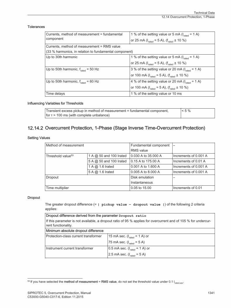
Tolerances
Currents, method of measurement = fundamentalcomponent
1 % of the setting value or 5 mA (Irated = 1 A)or 25 mA (Irated = 5 A), (frated ± 10 %)
Currents, method of measurement = RMS value(33 % harmonics, in relation to fundamental component)Up to 30th harmonic 1 % of the setting value or 5 mA (Irated = 1 A)
or 25 mA (Irated = 5 A), (frated ± 10 %)
Up to 50th harmonic, frated = 50 Hz 3 % of the setting value or 20 mA (Irated = 1 A)or 100 mA (Irated = 5 A), (frated ± 10 %)
Up to 50th harmonic, frated = 60 Hz 4 % of the setting value or 20 mA (Irated = 1 A)or 100 mA (Irated = 5 A), (frated ± 10 %)
Time delays 1 % of the setting value or 10 ms
Influencing Variables for Thresholds
Transient excess pickup in method of measurement = fundamental component,for τ > 100 ms (with complete unbalance)
< 5 %
Overcurrent Protection, 1-Phase (Stage Inverse Time-Overcurrent Protection)
Setting Values
Method of measurement Fundamental componentRMS value
–
Threshold value53 1 A @ 50 and 100 Irated 0.030 A to 35.000 A Increments of 0.001 A5 A @ 50 and 100 Irated 0.15 A to 175.00 A Increments of 0.01 A1 A @ 1.6 Irated 0.001 A to 1.600 A Increments of 0.001 A5 A @ 1.6 Irated 0.005 A to 8.000 A Increments of 0.001 A
Dropout Disk emulationInstantaneous
–
Time multiplier 0.05 to 15.00 Increments of 0.01
Dropout
The greater dropout difference (= | pickup value – dropout value |) of the following 2 criteriaapplies:
Dropout difference derived from the parameter Dropout ratioIf this parameter is not available, a dropout ratio of 95 % applies for overcurrent and of 105 % for undercur-rent functionality.Minimum absolute dropout differenceProtection-class current transformer 15 mA sec. (Irated = 1 A) or
75 mA sec. (Irated = 5 A)
Instrument current transformer 0.5 mA sec. (Irated = 1 A) or2.5 mA sec. (Irated = 5 A)
12.14.2
53 If you have selected the method of measurement = RMS value, do not set the threshold value under 0.1 lrated,sec.
Technical Data12.14 Overcurrent Protection, 1-Phase
SIPROTEC 5, Overcurrent Protection, Manual 1341C53000-G5040-C017-6, Edition 11.2015

Operate Curves and Dropout-Time Characteristic Curves According to IEC
Extension of the operate time during operation with transformer inrush-current detection
Approx. 10 ms
The tripping characteristic curves and dropout characteristic curves according to IEC can be found in theTechnical Data chapter under Inverse Time-Overcurrent Protection.
Operate Curves and Dropout-Time Characteristic Curves According to ANSI/IEEE
The tripping characteristic curves and dropout characteristic curves according to ANSI/IEEE can be found inthe Technical Data chapter under Inverse Time-Overcurrent Protection.
Frequency Operating Range
0.9 f/frated to 1.1 f/frated According to specified tolerances
10 Hz to 0.9 f/frated
1.1 f/frated to 80 HzSlightly expanded tolerances
f < 10 Hzf > 80 Hz
Active
Tolerances
Currents, method of measurement = fundamentalcomponent
1 % of the setting value or 5 mA (Irated = 1 A)or 25 mA (Irated = 5 A), (frated ± 10 %)
Currents, method of measurement = RMS value(33 % harmonics, in relation to fundamental component)Up to 30th harmonic 1 % of the setting value or 5 mA (Irated = 1 A)
or 25 mA (Irated = 5 A), (frated ± 10 %)
Up to 50th harmonic, frated = 50 Hz 3 % of the setting value or 20 mA (Irated = 1 A)or 100 mA (Irated = 5 A), (frated ± 10 %)
Up to 50th harmonic, frated = 60 Hz 4 % of the setting value or 20 mA (Irated = 1 A)or 100 mA (Irated = 5 A), (frated ± 10 %)
Operate time for 2 ≤ I/I threshold value ≤ 20 5 % of the setting value or +2 % current tolerance or30 ms
Dropout time for I/I threshold value ≤ 0.90 5 % of the setting value or +2 % current tolerance or30 ms
Influencing Variables for Thresholds
Transient excess pickup in method of measurement = fundamental component,for τ > 100 ms (with complete unbalance)
< 5 %
Overcurrent Protection, 1-Phase with User-Defined Characteristic Curve
Setting Values
Method of measurement Fundamental componentRMS value
–
Threshold value 1 A @ 50 and 100 Irated 0.030 A to 35.000 A Increments of 0.001 A5 A @ 50 and 100 Irated 0.15 A to 175.00 A Increments of 0.01 A1 A @ 1.6 Irated 0.001 A to 1.600 A Increments of 0.001 A5 A @ 1.6 Irated 0.005 A to 8.000 A Increments of 0.001 A
12.14.3
Technical Data12.14 Overcurrent Protection, 1-Phase
1342 SIPROTEC 5, Overcurrent Protection, ManualC53000-G5040-C017-6, Edition 11.2015
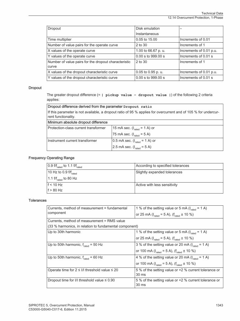
Dropout Disk emulationInstantaneous
–
Time multiplier 0.05 to 15.00 Increments of 0.01Number of value pairs for the operate curve 2 to 30 Increments of 1X values of the operate curve 1.00 to 66.67 p. u. Increments of 0.01 p.u.Y values of the operate curve 0.00 s to 999.00 s Increments of 0.01 sNumber of value pairs for the dropout characteristiccurve
2 to 30 Increments of 1
X values of the dropout characteristic curve 0.05 to 0.95 p. u. Increments of 0.01 p.u.Y values of the dropout characteristic curve 0.00 s to 999.00 s Increments of 0.01 s
Dropout
The greater dropout difference (= | pickup value – dropout value |) of the following 2 criteriaapplies:
Dropout difference derived from the parameter Dropout ratioIf this parameter is not available, a dropout ratio of 95 % applies for overcurrent and of 105 % for undercur-rent functionality.Minimum absolute dropout differenceProtection-class current transformer 15 mA sec. (Irated = 1 A) or
75 mA sec. (Irated = 5 A)
Instrument current transformer 0.5 mA sec. (Irated = 1 A) or2.5 mA sec. (Irated = 5 A)
Frequency Operating Range
0.9 f/frated to 1.1 f/frated According to specified tolerances
10 Hz to 0.9 f/frated
1.1 f/frated to 80 HzSlightly expanded tolerances
f < 10 Hzf > 80 Hz
Active with less sensitivity
Tolerances
Currents, method of measurement = fundamentalcomponent
1 % of the setting value or 5 mA (Irated = 1 A)or 25 mA (Irated = 5 A), (frated ± 10 %)
Currents, method of measurement = RMS value(33 % harmonics, in relation to fundamental component)Up to 30th harmonic 1 % of the setting value or 5 mA (Irated = 1 A)
or 25 mA (Irated = 5 A), (frated ± 10 %)
Up to 50th harmonic, frated = 50 Hz 3 % of the setting value or 20 mA (Irated = 1 A)or 100 mA (Irated = 5 A), (frated ± 10 %)
Up to 50th harmonic, frated = 60 Hz 4 % of the setting value or 20 mA (Irated = 1 A)or 100 mA (Irated = 5 A), (frated ± 10 %)
Operate time for 2 ≤ I/I threshold value ≤ 20 5 % of the setting value or +2 % current tolerance or30 ms
Dropout time for I/I threshold value ≤ 0.90 5 % of the setting value or +2 % current tolerance or30 ms
Technical Data12.14 Overcurrent Protection, 1-Phase
SIPROTEC 5, Overcurrent Protection, Manual 1343C53000-G5040-C017-6, Edition 11.2015

Influencing Variables for Thresholds
Transient excess pickup in method of measurement = fundamental component,for τ > 100 ms (with complete unbalance)
< 5 %
Operate Curves and Dropout-Time Characteristic Curves According to IEC
Extension of the operate time during operation with transformer inrush-current detection
Approx. 10 ms
Technical Data12.14 Overcurrent Protection, 1-Phase
1344 SIPROTEC 5, Overcurrent Protection, ManualC53000-G5040-C017-6, Edition 11.2015
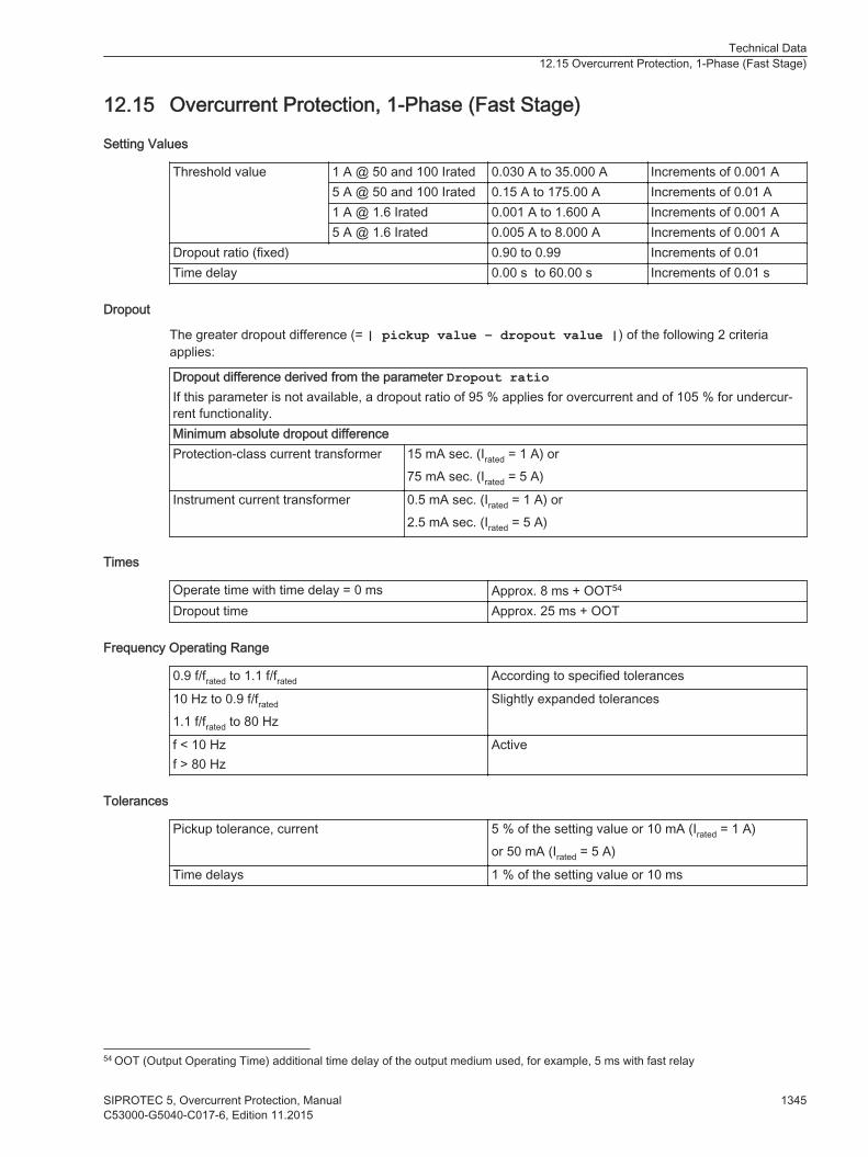
Overcurrent Protection, 1-Phase (Fast Stage)
Setting Values
Threshold value 1 A @ 50 and 100 Irated 0.030 A to 35.000 A Increments of 0.001 A5 A @ 50 and 100 Irated 0.15 A to 175.00 A Increments of 0.01 A1 A @ 1.6 Irated 0.001 A to 1.600 A Increments of 0.001 A5 A @ 1.6 Irated 0.005 A to 8.000 A Increments of 0.001 A
Dropout ratio (fixed) 0.90 to 0.99 Increments of 0.01Time delay 0.00 s to 60.00 s Increments of 0.01 s
Dropout
The greater dropout difference (= | pickup value – dropout value |) of the following 2 criteriaapplies:
Dropout difference derived from the parameter Dropout ratioIf this parameter is not available, a dropout ratio of 95 % applies for overcurrent and of 105 % for undercur-rent functionality.Minimum absolute dropout differenceProtection-class current transformer 15 mA sec. (Irated = 1 A) or
75 mA sec. (Irated = 5 A)
Instrument current transformer 0.5 mA sec. (Irated = 1 A) or2.5 mA sec. (Irated = 5 A)
Times
Operate time with time delay = 0 ms Approx. 8 ms + OOT54
Dropout time Approx. 25 ms + OOT
Frequency Operating Range
0.9 f/frated to 1.1 f/frated According to specified tolerances
10 Hz to 0.9 f/frated
1.1 f/frated to 80 HzSlightly expanded tolerances
f < 10 Hzf > 80 Hz
Active
Tolerances
Pickup tolerance, current 5 % of the setting value or 10 mA (Irated = 1 A)or 50 mA (Irated = 5 A)
Time delays 1 % of the setting value or 10 ms
12.15
54 OOT (Output Operating Time) additional time delay of the output medium used, for example, 5 ms with fast relay
Technical Data12.15 Overcurrent Protection, 1-Phase (Fast Stage)
SIPROTEC 5, Overcurrent Protection, Manual 1345C53000-G5040-C017-6, Edition 11.2015
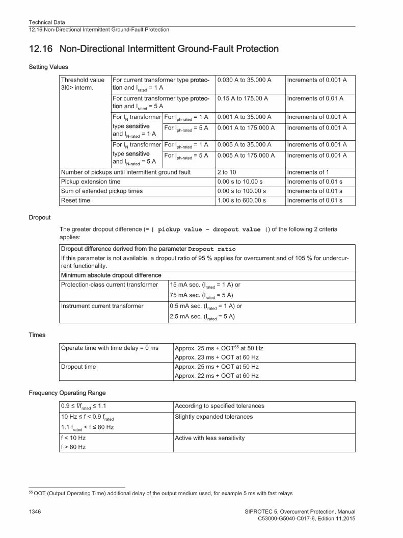
Non-Directional Intermittent Ground-Fault Protection
Setting Values
Threshold value3I0> interm.
For current transformer type protec-tion and Irated = 1 A
0.030 A to 35.000 A Increments of 0.001 A
For current transformer type protec-tion and Irated = 5 A
0.15 A to 175.00 A Increments of 0.01 A
For IN transformertype sensitiveand IN-rated = 1 A
For Iph-rated = 1 A 0.001 A to 35.000 A Increments of 0.001 A
For Iph-rated = 5 A 0.001 A to 175.000 A Increments of 0.001 A
For IN transformertype sensitiveand IN-rated = 5 A
For Iph-rated = 1 A 0.005 A to 35.000 A Increments of 0.001 A
For Iph-rated = 5 A 0.005 A to 175.000 A Increments of 0.001 A
Number of pickups until intermittent ground fault 2 to 10 Increments of 1Pickup extension time 0.00 s to 10.00 s Increments of 0.01 sSum of extended pickup times 0.00 s to 100.00 s Increments of 0.01 sReset time 1.00 s to 600.00 s Increments of 0.01 s
Dropout
The greater dropout difference (= | pickup value – dropout value |) of the following 2 criteriaapplies:
Dropout difference derived from the parameter Dropout ratioIf this parameter is not available, a dropout ratio of 95 % applies for overcurrent and of 105 % for undercur-rent functionality.Minimum absolute dropout differenceProtection-class current transformer 15 mA sec. (Irated = 1 A) or
75 mA sec. (Irated = 5 A)
Instrument current transformer 0.5 mA sec. (Irated = 1 A) or2.5 mA sec. (Irated = 5 A)
Times
Operate time with time delay = 0 ms Approx. 25 ms + OOT55 at 50 HzApprox. 23 ms + OOT at 60 Hz
Dropout time Approx. 25 ms + OOT at 50 HzApprox. 22 ms + OOT at 60 Hz
Frequency Operating Range
0.9 ≤ f/frated ≤ 1.1 According to specified tolerances
10 Hz ≤ f < 0.9 frated
1.1 frated < f ≤ 80 HzSlightly expanded tolerances
f < 10 Hzf > 80 Hz
Active with less sensitivity
12.16
55 OOT (Output Operating Time) additional delay of the output medium used, for example 5 ms with fast relays
Technical Data12.16 Non-Directional Intermittent Ground-Fault Protection
1346 SIPROTEC 5, Overcurrent Protection, ManualC53000-G5040-C017-6, Edition 11.2015
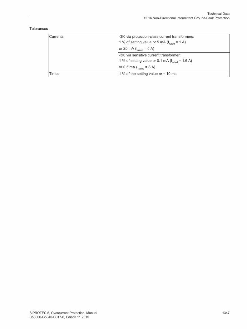
Tolerances
Currents -3I0 via protection-class current transformers:1 % of setting value or 5 mA (Irated = 1 A)or 25 mA (Irated = 5 A)
-3I0 via sensitive current transformer:1 % of setting value or 0.1 mA (Irated = 1.6 A)or 0.5 mA (Irated = 8 A)
Times 1 % of the setting value or ± 10 ms
Technical Data12.16 Non-Directional Intermittent Ground-Fault Protection
SIPROTEC 5, Overcurrent Protection, Manual 1347C53000-G5040-C017-6, Edition 11.2015

Directional Intermittent Ground-Fault Protection
Setting Values
Threshold value 3I0> For current transformer typeprotection and Irated = 1 A
0.030 A to 35.000 A Increments of 0.001 A
For current transformer typeprotection and Irated = 5 A
0.15 A to 175.00 A Increments of 0.01 A
For IN transformertype sensitive andIN-rated = 1 A
For Iph-rated = 1 A 0.001 A to 35.000 A Increments of 0.001 A
For Iph-rated = 5 A 0.001 A to 175.00 A Increments of 0.001 A
For IN transformertype sensitive andIN-rated = 5 A
For Iph-rated = 1 A 0.005 A to 35.000 A Increments of 0.001 A
For Iph-rated = 5 A 0.005 A to 175.00 A Increments of 0.001 A
Number of pulses until intermittent groundfault
2 to 10 Increments of 1
Pickup extension time 0.00 s to 10.00 s Increments of 0.01 sSum of extended pickup times 0.00 s to 100.00 s Increments of 0.01 sReset time 1.00 s to 600.00 s Increments of 0.01 sNumber of pulses for operate 2 to 100 Increments of 1
Dropout
The greater dropout difference (= | pickup value – dropout value |) of the following 2 criteriaapplies:
Dropout difference derived from the parameter Dropout ratioIf this parameter is not available, a dropout ratio of 95 % applies for overcurrent and of 105 % for undercur-rent functionality.Minimum absolute dropout differenceProtection-class current transformer 15 mA sec. (Irated = 1 A) or
75 mA sec. (Irated = 5 A)
Instrument current transformer 0.5 mA sec. (Irated = 1 A) or2.5 mA sec. (Irated = 5 A)
Times
Pickup time Approx. 30 ms + OOT56 at 50 HzApprox. 23 ms + OOT at 60 Hz
Dropout time Approx. 25 ms + OOT at 50 HzApprox. 22 ms + OOT at 60 Hz
Frequency Operating Range
0.9 ≤ f/frated ≤ 1.1 According to specified tolerances
10 Hz ≤ f < 0.9 frated
1.1 frated < f ≤ 80 HzSlightly expanded tolerances
f < 10 Hzf > 80 Hz
Active with less sensitivity
12.17
56 OOT (Output Operating Time) additional delay of the output medium used, for example 5 ms with fast relays
Technical Data12.17 Directional Intermittent Ground-Fault Protection
1348 SIPROTEC 5, Overcurrent Protection, ManualC53000-G5040-C017-6, Edition 11.2015
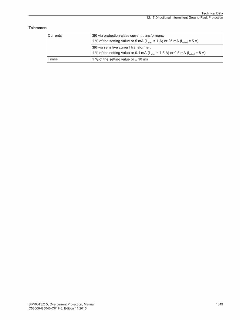
Tolerances
Currents 3I0 via protection-class current transformers:1 % of the setting value or 5 mA (Irated = 1 A) or 25 mA (Irated = 5 A)
3I0 via sensitive current transformer:1 % of the setting value or 0.1 mA (Irated = 1.6 A) or 0.5 mA (Irated = 8 A)
Times 1 % of the setting value or ± 10 ms
Technical Data12.17 Directional Intermittent Ground-Fault Protection
SIPROTEC 5, Overcurrent Protection, Manual 1349C53000-G5040-C017-6, Edition 11.2015

Sensitive Ground-Fault Detection
General
Setting Values
Decay time V0 0.06 s to 0.20 s Increments of 0.01 sDropout delay 0.00 s to 60.00 s Increments of 0.01 sCore balancecurrent transformercurrent 1Core balancecurrent transformercurrent 2
Protection-classcurrent trans-formers
For Iph-rated = 1 A 0.030 A to35.000 A
Increments of 0.001 A
For Iph-rated = 5 A 0.15 A to 175.00 A Increments of 0.01 A
For IN transformertype sensitive andIN-rated = 1 A
For Iph-rated = 1 A 0.001 A to35.000 A
Increments of 0.001 A
For Iph-rated = 5 A 0.001 A to175.000 A
Increments of 0.001 A
For IN transformertype sensitive andIN-rated = 5 A
For Iph-rated = 1 A 0.005 A to35.000 A
Increments of 0.001 A
For Iph-rated = 5 A 0.005 A to175.000 A
Increments of 0.001 A
Core balance current transformer angle correction F1Core balance current transformer angle correction F2
0.0° to 5.0° Increments of 0.1°
Frequency Operating Range
0.9 f/frated to 1.1 f/frated According to specified tolerances
10 Hz to 0.9 f/frated
1.1 f/frated to 80 HzSlightly expanded tolerances 57
f < 10 Hzf > 80 Hz
Active with less sensitivity 58
Tolerances
Currents -3I0 via sensitive current transformer:1 % of the setting value or 0.1 mA (Irated = 1.6 A)or 0.5 mA (Irated = 8 A, frated ± 10 %)
-3I0 via protection-class current transformers:1 % of the setting value or 5 mA (Irated = 1 A)or 25 mA (Irated = 5 A, frated ± 10 %)
Voltages 1 % of the setting value or 0.05 VTimes 1 % of the setting value or ±10 msDirection-calculation angle error ≤ 1° at 3I0 > 5 mA, V0 = 0.6 V
≤ 2° at 3I0 ≤ 5 mA, V0 = 0.6 V
Dropout
The greater dropout difference (= | pickup value – dropout value |) of the following 2 criteriaapplies:
12.18
12.18.1
57 Transient ground-fault stage is inactive58 Transient ground-fault stage is inactive
Technical Data12.18 Sensitive Ground-Fault Detection
1350 SIPROTEC 5, Overcurrent Protection, ManualC53000-G5040-C017-6, Edition 11.2015

Dropout difference derived from the parameter Dropout ratioIf this parameter is not available, a dropout ratio of 95 % applies for overcurrent/overvoltage and of 105 %for undercurrent/undervoltage functionality.Minimum absolute dropout differenceProtection-class current transformer 15 mA sec. (Irated = 1 A) or
75 mA sec. (Irated = 5 A)
Instrument current transformer 0.5 mA sec. (Irated = 1 A) or2.5 mA sec. (Irated = 5 A)
Voltage transformer 150 mV sec.
Overvoltage Protection Stage with Zero-Sequence System/Residual Voltage
You can find the the Technical data of the overvoltage protection stage with zero-sequence system/residualvoltage chapter 12.29 Overvoltage Protection with Zero-Sequence Voltage/Residual Voltage .
Directional Overcurrent-Protection Stage with cos φ or sin φ Measurement
Setting Values
Direction method of measurement cos φsin φ
–
Threshold value3I0>Minimum direc-tional 3I0> fordirection deter-mination
Protection-class currenttransformers
For Iph-rated = 1 A 0.030 A to 35.000 A Increments of 0.001 A
For Iph-rated = 5 A 0.15 A to 175.00 A Increments of 0.01 A
For IN transformer typesensitive and IN-rated = 1A
For Iph-rated = 1 A 0.001 A to 35.000 A Increments of 0.001 A
For Iph-rated = 5 A 0.001 A to 175.000 A Increments of 0.001 A
For IN transformer typesensitive and IN-rated = 5A
For Iph-rated = 1 A 0.005 A to 35.000 A Increments of 0.001 A
For Iph-rated = 5 A 0.005 A to 175.000 A Increments of 0.001 A
Threshold value V0> 0.300 V to 200.000 V Increments of 0.001 VTime delay of the direction determination 0.00 s to 60.00 s Increments of 0.01 sα1 constraint of the direction rangeα2 constraint of the direction range
1° to 15° Increments of 1°
Angle correction φ -45° to 45° Increments of 1°Tripping delay 0.00 s to 60.00 s Increments of 0.01 s
Dropout
The greater dropout difference (= | pickup value – dropout value |) of the following 2 criteriaapplies:
Dropout difference derived from the parameter Dropout ratioIf this parameter is not available, a dropout ratio of 95 % applies for overcurrent and of 105 % for undercur-rent functionality.Minimum absolute dropout differenceProtection-class current transformer 15 mA sec. (Irated = 1 A) or
75 mA sec. (Irated = 5 A)
Instrument current transformer 0.5 mA sec. (Irated = 1 A) or2.5 mA sec. (Irated = 5 A)
12.18.2
12.18.3
Technical Data12.18 Sensitive Ground-Fault Detection
SIPROTEC 5, Overcurrent Protection, Manual 1351C53000-G5040-C017-6, Edition 11.2015

Times
Operate time with time delay = 0 ms Approx. 32 ms + OOT59 at 50 HzApprox. 29 ms + OOT at 60 Hz
Extension of the operate time during operation with transformer inrush-current detection
Approx. 10 ms
Dropout time Approx. 32 ms + OOT at 50 HzApprox. 27 ms + OOT at 60 Hz
Directional Overcurrent-Protection Stage with 3I0-φ(V,I) Measurement
Setting Values
Threshold value3I0>
Protection-classcurrent transformers
For Iph-rated = 1 A 0.030 A to 35.000 A Increments of 0.001 A
For Iph-rated = 5 A 0.15 A to 175.00 A Increments of 0.01 A
For IN transformer typesensitive and IN-rated
= 1 A
For Iph-rated = 1 A 0.001 A to 35.000 A Increments of 0.001 A
For Iph-rated = 5 A 0.001 A to 175.000 A Increments of 0.001 A
For IN transformer typesensitive and IN-rated
= 5 A
For Iph-rated = 1 A 0.005 A to 35.000 A Increments of 0.001 A
For Iph-rated = 5 A 0.005 A to 175.000 A Increments of 0.001 A
Min. V0> for direction determination 0.300 V to 200.000 V Increments of 0.001 VTime delay of the direction determination 0.00 s to 60.00 s Increments of 0.01 sRotation angle of the reference voltage -180° to 180° Increments of 1°Forward range +/- 0° to 90° Increments of 1°Tripping delay 0.00 s to 60.00 s Increments of 0.01 s
Dropout
The greater dropout difference (= | pickup value – dropout value |) of the following 2 criteriaapplies:
Dropout difference derived from the parameter Dropout ratioIf this parameter is not available, a dropout ratio of 95 % applies for overcurrent and of 105 % for undercur-rent functionality.Minimum absolute dropout differenceProtection-class current transformer 15 mA sec. (Irated = 1 A) or
75 mA sec. (Irated = 5 A)
Instrument current transformer 0.5 mA sec. (Irated = 1 A) or2.5 mA sec. (Irated = 5 A)
Times
Operate time with time delay = 0 ms Approx. 23 ms + OOT60 at 50 HzApprox. 21 ms + OOT at 60 Hz
Extension of operate time during operation with transformerinrush-current detection
Approx. 10 ms
Dropout time Approx. 21 ms + OOT at 50 HzApprox. 20 ms + OOT at 60 Hz
12.18.4
59 OOT (Output Operating Time) additional delay of the output medium used, see Chapter 12.1.4 Relay Outputs60 OOT (Output Operating Time) additional delay of the output medium used, see chapter 12.1.4 Relay Outputs
Technical Data12.18 Sensitive Ground-Fault Detection
1352 SIPROTEC 5, Overcurrent Protection, ManualC53000-G5040-C017-6, Edition 11.2015
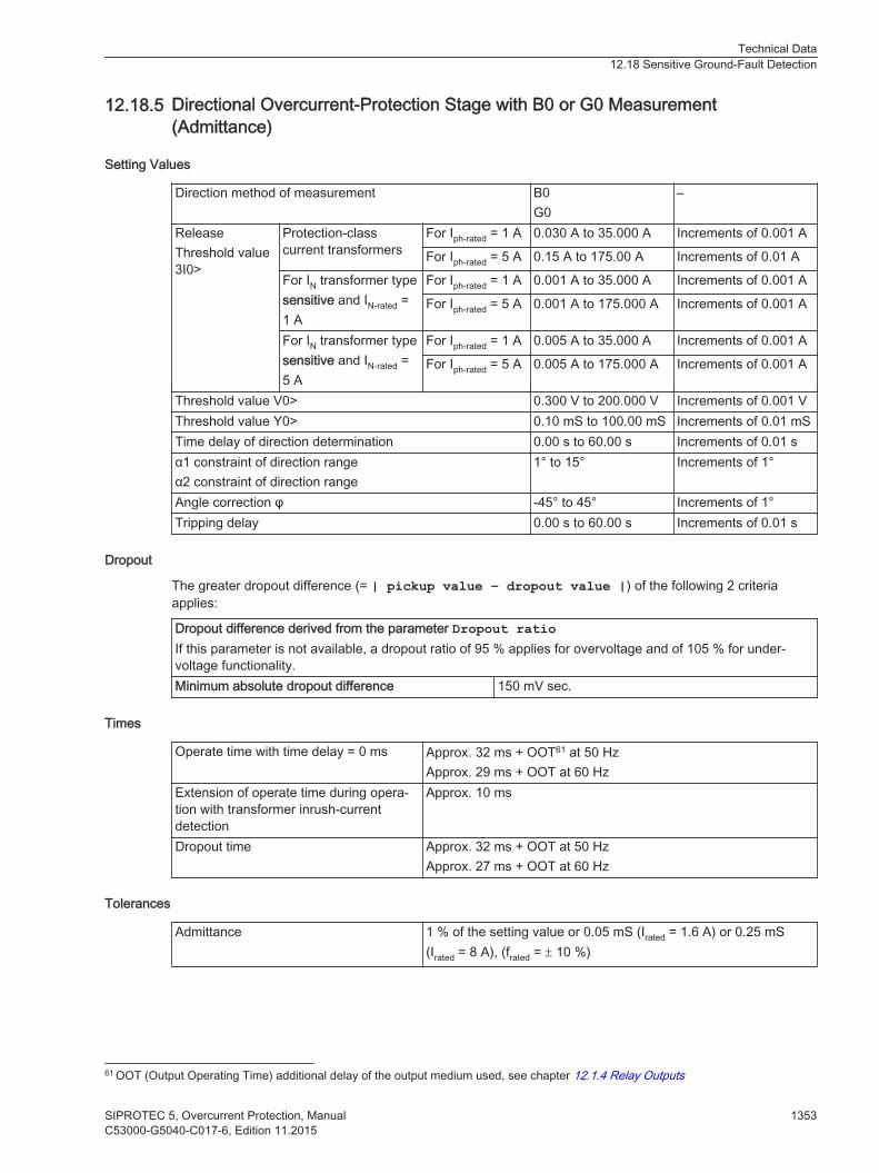
Directional Overcurrent-Protection Stage with B0 or G0 Measurement(Admittance)
Setting Values
Direction method of measurement B0G0
–
ReleaseThreshold value3I0>
Protection-classcurrent transformers
For Iph-rated = 1 A 0.030 A to 35.000 A Increments of 0.001 A
For Iph-rated = 5 A 0.15 A to 175.00 A Increments of 0.01 A
For IN transformer typesensitive and IN-rated =1 A
For Iph-rated = 1 A 0.001 A to 35.000 A Increments of 0.001 A
For Iph-rated = 5 A 0.001 A to 175.000 A Increments of 0.001 A
For IN transformer typesensitive and IN-rated =5 A
For Iph-rated = 1 A 0.005 A to 35.000 A Increments of 0.001 A
For Iph-rated = 5 A 0.005 A to 175.000 A Increments of 0.001 A
Threshold value V0> 0.300 V to 200.000 V Increments of 0.001 VThreshold value Y0> 0.10 mS to 100.00 mS Increments of 0.01 mSTime delay of direction determination 0.00 s to 60.00 s Increments of 0.01 sα1 constraint of direction rangeα2 constraint of direction range
1° to 15° Increments of 1°
Angle correction φ -45° to 45° Increments of 1°Tripping delay 0.00 s to 60.00 s Increments of 0.01 s
Dropout
The greater dropout difference (= | pickup value – dropout value |) of the following 2 criteriaapplies:
Dropout difference derived from the parameter Dropout ratioIf this parameter is not available, a dropout ratio of 95 % applies for overvoltage and of 105 % for under-voltage functionality.Minimum absolute dropout difference 150 mV sec.
Times
Operate time with time delay = 0 ms Approx. 32 ms + OOT61 at 50 HzApprox. 29 ms + OOT at 60 Hz
Extension of operate time during opera-tion with transformer inrush-currentdetection
Approx. 10 ms
Dropout time Approx. 32 ms + OOT at 50 HzApprox. 27 ms + OOT at 60 Hz
Tolerances
Admittance 1 % of the setting value or 0.05 mS (Irated = 1.6 A) or 0.25 mS(Irated = 8 A), (frated = ± 10 %)
12.18.5
61 OOT (Output Operating Time) additional delay of the output medium used, see chapter 12.1.4 Relay Outputs
Technical Data12.18 Sensitive Ground-Fault Detection
SIPROTEC 5, Overcurrent Protection, Manual 1353C53000-G5040-C017-6, Edition 11.2015

Sensitive Ground-Current Protection with Y0
Setting Values
V0> threshold value 0.300 V to 200.000 V Increments of 0.001 VThreshold Y0> 0.10 mS to 100.00 mS Increments of 0.01 mSPickup delay 0.00 s to 60.00 s Increments of 0.01 sOperate delay 0.00 s to 60.00 s Increments of 0.01 s
Dropout
The greater dropout difference (= | pickup value – dropout value |) of the following 2 criteriaapplies:
Dropout difference derived from the parameter Dropout ratioIf this parameter is not available, a dropout ratio of 95 % applies for overvoltage and of 105 % for under-voltage functionality.Minimum absolute dropout difference 150 mV sec.
Times
Operate time with time delay = 0 ms Approx. 32 ms + OOT62 at 50 HzApprox. 29 ms + OOT at 60 Hz
Extension of operate time during operationwith transformer inrush-current detection
Approx. 10 ms
Dropout time Approx. 32 ms + OOT at 50 HzApprox. 27 ms + OOT at 60 Hz
Tolerances
Admittance 1 % of the setting value or 0.05 mS (Irated = 1.6 A) or 0.25 mS(Irated = 8 A), (frated = ± 10 %)
Transient Ground-Fault Stage
Setting Values
Threshold value3I0>
Protection-classcurrent transformers
For Iph-rated = 1 A 0.030 A to 35.000 A Increments of 0.001 A
For Iph-rated = 5 A 0.15 A to 175.00 A Increments of 0.01 A
For IN transformertype sensitive and IN-
rated = 1 A
For Iph-rated = 1 A 0.001 A to 1.600 A Increments of 0.001 A
For Iph-rated = 5 A 0.005 A to 8.000 A Increments of 0.001 A
For IN transformertype sensitive and IN-
rated = 5 A
For Iph-rated = 1 A 0.001 A to 1.600 A Increments of 0.001 A
For Iph-rated = 5 A 0.005 A to 8.000 A Increments of 0.001 A
Threshold value V0> 0.300 V to 200.000 V Increments of 0.001 VTripping delay 0.00 s to 60.00 s Increments of 0.01 s
12.18.6
12.18.7
62 OOT (Output Operating Time) additional delay of the output medium used, see chapter 12.1.4 Relay Outputs
Technical Data12.18 Sensitive Ground-Fault Detection
1354 SIPROTEC 5, Overcurrent Protection, ManualC53000-G5040-C017-6, Edition 11.2015

Times
Operate time with time delay = 0 ms Approx. 115 ms + OOT63 at 50 HzApprox. 112 ms + OOT at 60 Hz
Dropout time Approx. 20 ms + OOT at 50 HzApprox. 15 ms + OOT at 60 Hz
Sensitive Ground-Current Protection with 3I0
Setting Values
Method of Measurement Fundamental componentRMS value
Threshold value3I0>
Protection-classcurrent transformers
For Iph-rated = 1 A 0.030 A to 35.000 A Increments of 0.001A
For Iph-rated = 5 A 0.15 A to 175.00 A Increments of 0.01 A
For transformer typeI-sensitive andIN-rated = 1 A
For Iph-rated = 1 A 0.001 A to 35.000 A Increments of 0.001A
For Iph-rated = 5 A 0.001 A to 175.000 A Increments of 0.001A
For transformer typeI-sensitive andIN-rated = 5 A
For Iph-rated = 1 A 0.005 A to 35.000 A Increments of 0.001A
For Iph-rated = 5 A 0.005 A to 175.000 A Increments of 0.001A
Pickup delay 0.00 s to 60.00 s Increments of 0.01 sTripping delay 0.00 s to 60.00 s Increments of 0.01 s
Dropout
The greater dropout difference (= | pickup value – dropout value |) of the following 2 criteriaapplies:
Dropout difference derived from the parameter Dropout ratioIf this parameter is not available, a dropout ratio of 95 % applies for overcurrent and of 105 % for undercur-rent functionality.Minimum absolute dropout differenceProtection-class current transformer 15 mA sec. (Irated = 1 A) or
75 mA sec. (Irated = 5 A)
Instrument current transformer 0.5 mA sec. (Irated = 1 A) or2.5 mA sec. (Irated = 5 A)
Times
Operate time with time delay = 0 ms Approx. 25 ms + OOT64 at 50 HzApprox. 23 ms + OOT at 60 Hz
Extension of the operate time during operation with trans-former inrush-current detection
Approx. 10 ms
Dropout time Approx. 25 ms + OOT at 50 HzApprox. 22 ms + OOT at 60 Hz
12.18.8
63 OOT (Output Operating Time) additional delay of the output medium used, see chapter 12.1.4 Relay Outputs64 OOT (Output Operating Time) additional delay of the output medium used, see chapter 12.1.4 Relay Outputs
Technical Data12.18 Sensitive Ground-Fault Detection
SIPROTEC 5, Overcurrent Protection, Manual 1355C53000-G5040-C017-6, Edition 11.2015

Undercurrent Protection
Setting Values
Method of measurement Fundamental componentRMS value
–
Threshold value I< 1 A @ 50 and 100 Irated 0.030 A to 35.000 A Increments of 0.001 A5 A @ 50 and 100 Irated 0.15 A to 175.00 A Increments of 0.01 A1 A @ 1.6 Irated 0.001 A to 1.600 A Increments of 0.001 A5 A @ 1.6 Irated 0.005 A to 8.000 A Increments of 0.001 A
Time delay 0.00 s to 60.00 s Increments of 0.01 s
Dropout
The greater dropout difference (= | pickup value – dropout value |) of the following 2 criteriaapplies:
Dropout difference derived from the parameter Dropout ratioIf this parameter is not available, a dropout ratio of 95 % applies for overcurrent and of 105 % for undercur-rent functionality.Minimum absolute dropout differenceProtection-class current transformer 15 mA sec. (Irated = 1 A) or
75 mA sec. (Irated = 5 A)
Instrument current transformer 0.5 mA sec. (Irated = 1 A) or2.5 mA sec. (Irated = 5 A)
Times
Operate time Approx. 25 ms + OOT65 at 50 HzApprox. 22 ms + OOT at 60 Hz
Dropout time Approx. 25 ms + OOT at 50 HzApprox. 22 ms + OOT at 60 Hz
Frequency Operating Range
0.9 ≤ f/frated ≤ 1.1 f/frated According to specified tolerances
10 Hz to 0.9 f/frated
1,1 f/frated to 80 HzSlightly expanded tolerances
f < 10 Hzf > 80 Hz
Inactive
Tolerances
Currents, method of measurement = fundamentalcomponent
1 % of setting value or 5 mA (Irated = 1 A)or 25 mA (Irated = 5 A), (frated ± 10 %)
Currents, method of measurement = RMS value(33 % portion harmonic, referring to fundamental component)Up to 30th harmonic 1 % of setting value or 5 mA (Irated = 1 A)
or 25 mA (Irated = 5 A), (frated ± 10 %)
12.19
65 OOT (Output Operating Time) additional delay of the output medium used, for example, 5 ms with fast relays, see Chapter RelayOutputs
Technical Data12.19 Undercurrent Protection
1356 SIPROTEC 5, Overcurrent Protection, ManualC53000-G5040-C017-6, Edition 11.2015

Up to 50th harmonic, frated = 50 Hz 3 % of setting value or 20 mA (Irated = 1 A)or 100 mA (Irated = 5 A), (frated ± 10 %)
Up to 50th harmonic, frated = 60 Hz 4 % of setting value or 20 mA (Irated = 1 A)or 100 mA (Irated = 5 A), (frated ± 10 %)
Time delays 1 % of the setting value or 10 ms
Technical Data12.19 Undercurrent Protection
SIPROTEC 5, Overcurrent Protection, Manual 1357C53000-G5040-C017-6, Edition 11.2015

Negative-Sequence Protection
Stage with Definite-Time Characteristic Curve
Setting Values
Reference value for I2 (Iref) Rated object current Irated, obj.
Positive-sequence current I1Pickup value 5.0 % to 999.9 % l2/lref Increments of 0.1
Dropout ratio 0.40 to 0.99 Increments of 0.01 Time delay 0.00 s to 60.00 s Increments of 0.01 sRelease current(minimum currentrelease)
1 A @ 50 and 100 Irated 0.030 A to 10.000 A Increments of 0.001 A5 A @ 50 and 100 Irated 0.15 A to 50.00 A Increments of 0.01 A1 A @ 1.6 Irated 0.001 A to 1.600 A Increments of 0.001 A5 A @ 1.6 Irated 0.005 A to 8.000 A Increments of 0.001 A
Maximum phasecurrent (maximumcurrent limiting)
1 A @ 50 and 100 Irated 0.030 A to 35.000 A Increments of 0.001 A5 A @ 50 and 100 Irated 0.15 A to 175.00 A Increments of 0.01 A1 A @ 1.6 Irated 0.001 A to 1.600 A Increments of 0.001 A5 A @ 1.6 Irated 0.005 A to 8.000 A Increments of 0.001 A
Dropout
The greater dropout difference (= | pickup value – dropout value |) of the following 2 criteriaapplies:• Dropout difference derived from the parameter Dropout ratio• Dropout difference of 3 % of the object rated current
Times
Pickup time Approx. 40 ms + OOT66 at 50 HzApprox. 35 ms + OOT at 60 Hz
Dropout time Approx. 35 ms + OOT
Current Operating Range
Current range At least one phase current ≥ setting value Irelease
All phase currents ≤ setting value Iph, max
Frequency Operating Range
0.9 ≤ f/frated ≤ 1.1 According to specified tolerances
10 Hz ≤ 0.9 frated
1.1 frated< f ≤ 80 HzSlightly expanded tolerances
f < 10 Hzf > 80 Hz
Inactive
12.20
12.20.1
66 OOT (Output Operating Time) additional delay of the output medium used, see chapter 12.1.4 Relay Outputs
Technical Data12.20 Negative-Sequence Protection
1358 SIPROTEC 5, Overcurrent Protection, ManualC53000-G5040-C017-6, Edition 11.2015
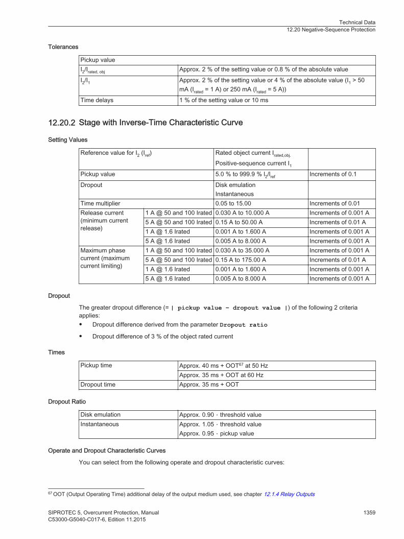
Tolerances
Pickup valueI2/Irated, obj Approx. 2 % of the setting value or 0.8 % of the absolute value
I2/I1 Approx. 2 % of the setting value or 4 % of the absolute value (I1 > 50mA (Irated = 1 A) or 250 mA (Irated = 5 A))
Time delays 1 % of the setting value or 10 ms
Stage with Inverse-Time Characteristic Curve
Setting Values
Reference value for I2 (Iref) Rated object current Irated,obj.
Positive-sequence current I1Pickup value 5.0 % to 999.9 % l2/lref Increments of 0.1
Dropout Disk emulationInstantaneous
Time multiplier 0.05 to 15.00 Increments of 0.01Release current(minimum currentrelease)
1 A @ 50 and 100 Irated 0.030 A to 10.000 A Increments of 0.001 A5 A @ 50 and 100 Irated 0.15 A to 50.00 A Increments of 0.01 A1 A @ 1.6 Irated 0.001 A to 1.600 A Increments of 0.001 A5 A @ 1.6 Irated 0.005 A to 8.000 A Increments of 0.001 A
Maximum phasecurrent (maximumcurrent limiting)
1 A @ 50 and 100 Irated 0.030 A to 35.000 A Increments of 0.001 A5 A @ 50 and 100 Irated 0.15 A to 175.00 A Increments of 0.01 A1 A @ 1.6 Irated 0.001 A to 1.600 A Increments of 0.001 A5 A @ 1.6 Irated 0.005 A to 8.000 A Increments of 0.001 A
Dropout
The greater dropout difference (= | pickup value – dropout value |) of the following 2 criteriaapplies:• Dropout difference derived from the parameter Dropout ratio• Dropout difference of 3 % of the object rated current
Times
Pickup time Approx. 40 ms + OOT67 at 50 HzApprox. 35 ms + OOT at 60 Hz
Dropout time Approx. 35 ms + OOT
Dropout Ratio
Disk emulation Approx. 0.90 ⋅ threshold valueInstantaneous Approx. 1.05 ⋅ threshold value
Approx. 0.95 ⋅ pickup value
Operate and Dropout Characteristic Curves
You can select from the following operate and dropout characteristic curves:
12.20.2
67 OOT (Output Operating Time) additional delay of the output medium used, see chapter 12.1.4 Relay Outputs
Technical Data12.20 Negative-Sequence Protection
SIPROTEC 5, Overcurrent Protection, Manual 1359C53000-G5040-C017-6, Edition 11.2015

Table 12-5 Standard Characteristic Curves to IEC
Normal inverse: type A See chapter 12.5.2 Inverse Time-Overcurrent Protection, Phases ,Figure 12-1Very inverse: type B
Extremely inverse: type C See chapter 12.5.2 Inverse Time-Overcurrent Protection, Phases ,Figure 12-2Long-time inverse: type B
Table 12-6 Standard Characteristic Curves to ANSI
Inverse: type C See chapter 12.5.2 Inverse Time-Overcurrent Protection, Phases ,Figure 12-3Short inverse
Long inverse See chapter 12.5.2 Inverse Time-Overcurrent Protection, Phases ,Figure 12-4Moderately inverse
Very inverse See chapter 12.5.2 Inverse Time-Overcurrent Protection, Phases ,Figure 12-5Extremely inverse
Definite inverse See chapter 12.5.2 Inverse Time-Overcurrent Protection, Phases ,Figure 12-6
Extension of the Operating Time
Extension of the operate timeduring operation with transformerinrush-current detection
Approx. 10 ms
Current Operating Range
Current range at least one phase current ≥ setting value Irelease
all phase currents ≤ setting value Iph, max
Frequency Operating Range
0.9 ≤ f/frated ≤ 1.1 According to specified tolerances
10 Hz ≤ 0.9 frated
1.1 frated< f ≤ 80 HzSlightly expanded tolerances
f < 10 Hzf > 80 Hz
Inactive
Tolerances
Reference value = rated currentPickup value Approx. 2 % of the setting value or 0.8 % of the absolute valueOperate time for 2 ≤ I/I thresholdvalue ≤ 20
5 % of the setting value or + 2 % of the current tolerance or 30 ms
Dropout time for I/I threshold value≤ 0.90
5 % of the setting value or + 2 % of the current tolerance or 30 ms
Reference value = pos. seq. currentPickup value Approx. 2 % of the setting value or 4 % of the absolute value (I1 > 50
mA (Irated = 1 A) or 250 mA (Irated = 5 A))
Operate time for 2 ≤ I/I thresholdvalue ≤ 20
5 % of the setting value or + 2 % of the current tolerance or 30 ms
Dropout time for I/I threshold value≤ 0.90
5 % of the setting value or + 2 % current tolerance or 30 ms
Technical Data12.20 Negative-Sequence Protection
1360 SIPROTEC 5, Overcurrent Protection, ManualC53000-G5040-C017-6, Edition 11.2015

Directional Negative-Sequence Protection with Definite-Time Delay
Setting Values
Directional mode Forward, backward, non-directionalStabilization with phase currents 0 % to 30 % Increments of 1 %
Threshold value (pickup value) at IN-rated = 1 A 0.030 A to 35.000 A Increments of 0.001 A
Threshold value (pickup value) at IN-rated = 5 A 0.15 A to 175.00 A Increments of 0.01 A
Extension time of the blocking after a 1-pole pause 0.00 s to 60.00 s Increments of 0.01 s
Setting Values for Direction Determination
Minimum negative-sequence system voltage V2 0.150 V to 20.000 V Increments of 0.001 VMinimum negative-sequence systemcurrent I2
For Irated = 1 A 0.030 A to 10.000 A Increments of 0.001 A
For Irated = 5 A 0.15 A to 50.00 A Increments of 0.01 A
Upper limit angle forward, β 0o to 360o Increments of 1o
Lower limit angle forward, α 0o to 360o Increments of 1o
Dropout
The greater dropout difference (= | pickup value – dropout value |) of the following 2 criteriaapplies:• Dropout difference derived from the parameter Dropout ratio• Dropout difference of 3 % of the object rated current
Times
Operate time with time delay = 0 ms Approx. 40 ms + OOT68 at 50 HzApprox. 40 ms + OOT at 60 Hz
Dropout time Approx. 39 ms + OOT
Operating Range
10 Hz to 80 Hz According to specified tolerancesOutside 10 Hz to 80 Hz Not active
Tolerances
Threshold values:Negative-sequence voltage V2 1 % of the setting value or 0.5 VNegative-sequence current I2 2 % of the setting value or 10 mA at Irated = 1 A
1 % of the setting value or 5 mA at Irated = 5 A
Times:Independent time delays 1 % of the setting value or 10 ms
Limit angle in determining the direction 5o
12.21
68 OOT (Output Operating Time) additional delay of the output medium used, see chapter 12.1.4 Relay Outputs
Technical Data12.21 Directional Negative-Sequence Protection with Definite-Time Delay
SIPROTEC 5, Overcurrent Protection, Manual 1361C53000-G5040-C017-6, Edition 11.2015

Thermal Overload Protection
Setting Values/Increments
Threshold current warning 1 A @ 50 and 100 Irated 0.030 A to 35.000 A Increments of 0.001 A5 A @ 50 and 100 Irated 0.15 A to 175.00 A Increments of 0.01 A1 A @ 1.6 Irated 0.001 A to 1.600 A Increments of 0.001 A5 A @ 1.6 Irated 0.005 A to 8.000 A Increments of 0.001 A
Threshold thermal warn. 50% to 100% Increments of 1 %Dropout threshold operate 50% to 99% Increments of 1 %Emerg. start T overtravel 0 s to 15 000 s Increments of 10 sK-factor acc. to IEC 60225-8 0.10 to 4.00 Increments of 0.01Thermal time constant 10 s to 60 000 s Increments of 1 sCooling time constant 10 s to 60 000 s Increments of 1 sImax thermal 1 A @ 50 and 100 Irated 0.030 A to 10.000 A Increments of 0.001 A
5 A @ 50 and 100 Irated 0.15 A to 50.00 A Increments of 0.01 A1 A @ 1.6 Irated 0.001 A to 1.600 A Increments of 0.001 A5 A @ 1.6 Irated 0.005 A to 8.000 A Increments of 0.001 A
Imin cooling 1 A @ 50 and 100 Irated 0.000 A to 10.000 A Increments of 0.001 A5 A @ 50 and 100 Irated 0.00 A to 50.00 A Increments of 0.01 A1 A @ 1.6 Irated 0.000 A to 1.600 A Increments of 0.001 A5 A @ 1.6 Irated 0.000 A to 8.000 A Increments of 0.001 A
temperature rise at Irated 40 K to 200 K Increments of 1 KDefault temperature -55°C to 55°C Increments of 1°CMinimal temperature -55°C to 40°C Increments of 1°C
Dropout Ratios
Tripping threshold (fixed at 100 %) Dropout if value drops below operate indication dropoutthreshold
Thermal warning threshold About 0.99 of the setting valueCurrent warning threshold About 0.95 of the setting value
Frequency Range of the Input Signals
The function captures input signals up to the 50th harmonic.
Tolerances
With reference to k* Irated For Irated = 1 A 2 % or 10 mA, class 2 % acc. to IEC 60255-8
For Irated = 5 A 2 % or 50 mA, class 2 % acc. to IEC 60255-8
With reference to operate time 3 % or 1 s, class 3 % acc. to IEC 60255-8 for I/(k *Irated) > 1.25
Operate Curve
Operate curve
12.22
Technical Data12.22 Thermal Overload Protection
1362 SIPROTEC 5, Overcurrent Protection, ManualC53000-G5040-C017-6, Edition 11.2015

The following meaningsapply:
t Operate timeτth Time constant
I Current load currentIpreload Preload current
k Setting factor according to VDE 0435 part 3011or IEC 60255-8 (K factor)
Irated, obj Rated current of the protected object
Technical Data12.22 Thermal Overload Protection
SIPROTEC 5, Overcurrent Protection, Manual 1363C53000-G5040-C017-6, Edition 11.2015

[dwauslke-100611-01.tif, 1, en_US]
Figure 12-15 Operate Curve of Overload Protection
Technical Data12.22 Thermal Overload Protection
1364 SIPROTEC 5, Overcurrent Protection, ManualC53000-G5040-C017-6, Edition 11.2015

Unbalanced-Load Protection
Setting Values
Maximum continuously perm. I2 3.0 % to 30.0 % l2/lrated,machine Increments of 0.1 %
Unbalanced load factor K 1.0 s to 100.0 s Increments of 0.1 sWarning delay 0.0 s to 60.0 s; ∞ Increments of 0.1 sCooling time thermal replica 0 s to 50 000 s Increments of 1 s
Dropout Ratio
Maximum continuously perm. I2 Approx. 0.95
Operate Characteristics
Characteristic of the thermal replica
Where: tI2Perm Permissible application time of the negative-sequence current
K Unbalanced load factor KI2/Irated,machine Unbalanced load (negative-sequence current/
rated current of the machine)
[dwunbaop-300913, 1, en_US]
Figure 12-16 Thermal Characteristic for Unbalanced Load Protection
Times
Pickup time of the warning stage Approx. 60 ms + OOT69 at 50 HzApprox. 50 ms + OOT at 60 Hz
Dropout time Approx. 50 ms or better
12.23
69 OOT (Output Operating Time) additional delay of the output medium used, for example, 5 ms with fast relays
Technical Data12.23 Unbalanced-Load Protection
SIPROTEC 5, Overcurrent Protection, Manual 1365C53000-G5040-C017-6, Edition 11.2015
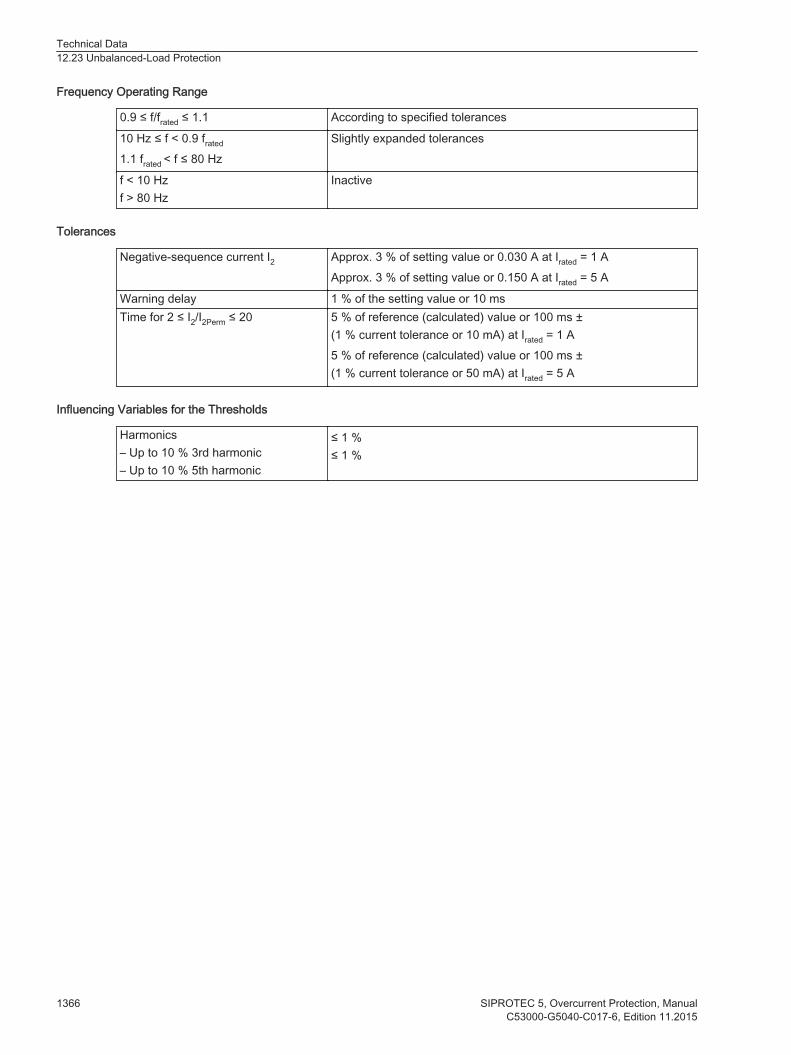
Frequency Operating Range
0.9 ≤ f/frated ≤ 1.1 According to specified tolerances
10 Hz ≤ f < 0.9 frated
1.1 frated < f ≤ 80 HzSlightly expanded tolerances
f < 10 Hzf > 80 Hz
Inactive
Tolerances
Negative-sequence current I2 Approx. 3 % of setting value or 0.030 A at Irated = 1 AApprox. 3 % of setting value or 0.150 A at Irated = 5 A
Warning delay 1 % of the setting value or 10 msTime for 2 ≤ I2/I2Perm ≤ 20 5 % of reference (calculated) value or 100 ms ±
(1 % current tolerance or 10 mA) at Irated = 1 A5 % of reference (calculated) value or 100 ms ±(1 % current tolerance or 50 mA) at Irated = 5 A
Influencing Variables for the Thresholds
Harmonics– Up to 10 % 3rd harmonic– Up to 10 % 5th harmonic
≤ 1 %≤ 1 %
Technical Data12.23 Unbalanced-Load Protection
1366 SIPROTEC 5, Overcurrent Protection, ManualC53000-G5040-C017-6, Edition 11.2015

Current-Unbalance Protection for Capacitors, 3-Phase
Setting Values for the Function
Automatic compensation YesNo
Time between switch off and switch on 0.00 s to 60.00 s Increments of 0.01 sNormalization with Ic Yes
NoThreshold of defectiveC-element
1 A @ 50 and 100 Irated 0.030 A to 35.000 A Increments of 0.001 A5 A @ 50 and 100 Irated 0.15 A to 175.00 A Increments of 0.01 A1 A @ 1.6 Irated 0.001 A to 1.600 A Increments of 0.001 A5 A @ 1.6 Irated 0.005 A to 8.000 A Increments of 0.001 A
Setting Values (Overcurrent-Protection Stage I>)
Measured value compensatednon-compensated
Iunbal. 1 A @ 50 and 100 Irated 0.030 A to 35.000 A Increments of 0.001 A5 A @ 50 and 100 Irated 0.15 A to 175.00 A Increments of 0.01 A
Iunbal. 1 A @ 1.6 Irated 0.001 A to 1.600 A Increments of 0.001 A5 A @ 1.6 Irated 0.005 A to 8.000 A Increments of 0.001 A
Operate delay 0.00 s to 60.00 s Increments of 0.01 s
Setting Values (Counter Stage)
Type of counting groups segregatedsum
Max. no. of def. elem. phs A 1 to 1000 Increments of 1Max. no. of def. elem. phs B 1 to 1000 Increments of 1Max. no. of def. elem. phs C 1 to 1000 Increments of 1Operate delay 0.00 s to 10000.00 s Increments of 0.01 s
Dropout Ratio
Threshold for defective C-element Approx. 0.95 of the current thresholdThreshold for overcurrent-protection stage I> Approx. 0.95 of the current threshold
Times
Operate time with time delay = 0 ms Approx. 32 ms + OOT70 at 50 HzApprox. 29 ms + OOT at 60 Hz
Dropout time Approx. 32 ms + OOT at 50 HzApprox. 27 ms + OOT at 60 Hz
Frequency Operating Range
0.9 f/frated to 1.1 f/frated According to specified tolerances
10 Hz to 0.9 f/frated
1.1 f/frated to 80 HzSlightly expanded tolerances
12.24
70 OOT (Output Operating Time) additional delay of the output medium used, see chapter 12.1.4 Relay Outputs
Technical Data12.24 Current-Unbalance Protection for Capacitors, 3-Phase
SIPROTEC 5, Overcurrent Protection, Manual 1367C53000-G5040-C017-6, Edition 11.2015

f < 10 Hzf > 80 Hz
Active
Tolerances
Currents Ic, Iunbal.
Protection-class current transformers1 % of the setting value or 5 mA (Irated = 1 A)or 25 mA (Irated = 5 A), (frated ± 10 %)
Currents Iunbal.
Sensitive current transformer1 % of the setting value or 0.1 mA (Irated = 1.6 A)or 0.5 mA (Irated = 8 A), (frated ± 10 %)
Time delays 1 % of the setting value or 10 ms
Technical Data12.24 Current-Unbalance Protection for Capacitors, 3-Phase
1368 SIPROTEC 5, Overcurrent Protection, ManualC53000-G5040-C017-6, Edition 11.2015
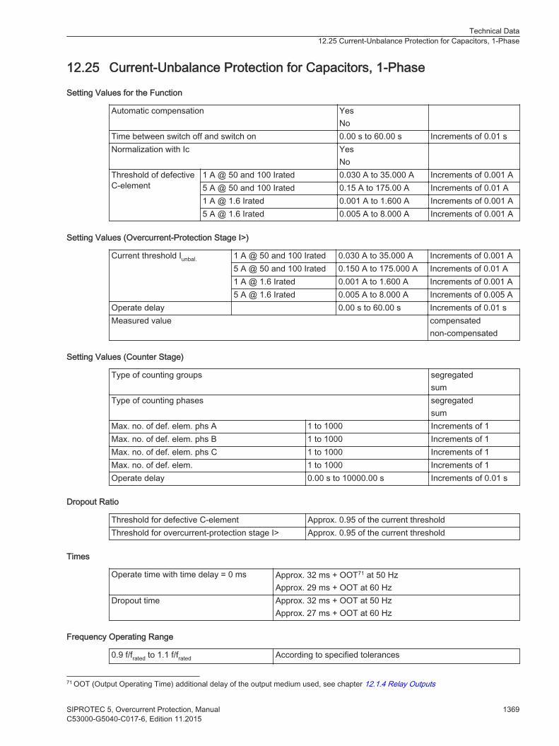
Current-Unbalance Protection for Capacitors, 1-Phase
Setting Values for the Function
Automatic compensation YesNo
Time between switch off and switch on 0.00 s to 60.00 s Increments of 0.01 sNormalization with Ic Yes
NoThreshold of defectiveC-element
1 A @ 50 and 100 Irated 0.030 A to 35.000 A Increments of 0.001 A5 A @ 50 and 100 Irated 0.15 A to 175.00 A Increments of 0.01 A1 A @ 1.6 Irated 0.001 A to 1.600 A Increments of 0.001 A5 A @ 1.6 Irated 0.005 A to 8.000 A Increments of 0.001 A
Setting Values (Overcurrent-Protection Stage I>)
Current threshold Iunbal. 1 A @ 50 and 100 Irated 0.030 A to 35.000 A Increments of 0.001 A5 A @ 50 and 100 Irated 0.150 A to 175.000 A Increments of 0.01 A1 A @ 1.6 Irated 0.001 A to 1.600 A Increments of 0.001 A5 A @ 1.6 Irated 0.005 A to 8.000 A Increments of 0.005 A
Operate delay 0.00 s to 60.00 s Increments of 0.01 sMeasured value compensated
non-compensated
Setting Values (Counter Stage)
Type of counting groups segregatedsum
Type of counting phases segregatedsum
Max. no. of def. elem. phs A 1 to 1000 Increments of 1Max. no. of def. elem. phs B 1 to 1000 Increments of 1Max. no. of def. elem. phs C 1 to 1000 Increments of 1Max. no. of def. elem. 1 to 1000 Increments of 1Operate delay 0.00 s to 10000.00 s Increments of 0.01 s
Dropout Ratio
Threshold for defective C-element Approx. 0.95 of the current thresholdThreshold for overcurrent-protection stage I> Approx. 0.95 of the current threshold
Times
Operate time with time delay = 0 ms Approx. 32 ms + OOT71 at 50 HzApprox. 29 ms + OOT at 60 Hz
Dropout time Approx. 32 ms + OOT at 50 HzApprox. 27 ms + OOT at 60 Hz
Frequency Operating Range
0.9 f/frated to 1.1 f/frated According to specified tolerances
12.25
71 OOT (Output Operating Time) additional delay of the output medium used, see chapter 12.1.4 Relay Outputs
Technical Data12.25 Current-Unbalance Protection for Capacitors, 1-Phase
SIPROTEC 5, Overcurrent Protection, Manual 1369C53000-G5040-C017-6, Edition 11.2015

10 Hz to 0.9 f/frated
1.1 f/frated to 80 HzSlightly expanded tolerances
f < 10 Hzf > 80 Hz
Active
Tolerances
Currents Ic, Iunbal.
Protection-class current transformers1 % of the setting value or 5 mA (Irated = 1 A)or 25 mA (Irated = 5 A), (frated ± 10%)
Currents Iunbal.
Sensitive current transformer1 % of the setting value or 0.1 mA (Irated = 1.6 A)or 0.5 mA (Irated = 8 A), (frated ± 10%)
Time delays 1 % of the setting value or 10 ms
Technical Data12.25 Current-Unbalance Protection for Capacitors, 1-Phase
1370 SIPROTEC 5, Overcurrent Protection, ManualC53000-G5040-C017-6, Edition 11.2015

Voltage-Differential Protection for Capacitor Banks
Setting Values (General Functionality)
Voltage matching factor k 0.5000 to 2000.0000 Increments of 0.0001
Setting Values (Protection Stage Vdiff>)
Threshold 0.005 p.u. to 1.000 p.u. Increments of 0.001 p.u.Operate delay 0.00 s to 60.00 s Increments of 0.01 s
Dropout Ratio
Threshold value Approx. 0.95
Times
Operate time with time delay = 0 ms Approx. 30 ms + OOT (Output Operating Time) at 50 HzApprox. 27 ms + OOT (Output Operating Time) at 60 Hz
Dropout time Approx. 20 ms + OOT (Output Operating Time) at 50 HzApprox. 18 ms + OOT (Output Operating Time) at 60 Hz
Tolerances
Threshold 1 % of the setting value or 0.05 VTime delays 1 % of the setting value or 10 ms
Frequency Operating Range
0.9 ≤ f/ frated ≤ 1.1 According to specified tolerances
10 Hz ≤ f ≤ 0.9 frated
1.1 frated ≤ f ≤ 80 HzSlightly expanded tolerances
f < 10 Hzf > 80 Hz
Active
12.26
Technical Data12.26 Voltage-Differential Protection for Capacitor Banks
SIPROTEC 5, Overcurrent Protection, Manual 1371C53000-G5040-C017-6, Edition 11.2015

Differential Protection for Capacitor Banks
Setting Values
Operate CurveThreshold value I/IratedObj 0.05 to 2.00 Increments of 0.01
Gradient 1 0.00 to 0.80 Increments of 0.01Intersection 1 Irest I/IratedObj 0.00 to 5.00 Increments of 0.01
Gradient 2 0.25 to 0.95 Increments of 0.01Intersection 2 Irest I/IratedObj 1.00 to 20.00 Increments of 0.01
Startup RecognitionStartup threshold value I/IratedObj 0.1 to 2.0 Increments of 0.1
Characteristic-curve increase factor 1.0 to 5.0 Increments of 0.1Maximum starting time 0.1 s to 180.0 s Increments of 0.1 sDC-Component RecognitionCharacteristic-curve increase factor DC 1.0 to 5.0 Increments of 0.1Inrush-current detectionContent 2nd harmonic 10 % to 45 % Increments of 1 %Duration of crossblk. 2. har. 0.00 s to 200.00 s or
∞Increments of 0.01 s
Recognition of External FaultsAdditional stabilization threshold value I/IratedObj 1.00 to 20.00 Increments of 0.01
Additional stabilization duration 0.00 s to 5.00 s or ∞ Increments of 0.01 sOperate curve See Figure 12-17
Idiff Fast
Threshold value I/IratedObj 0.5 to 35.0 Increments of 0.1
Tripping delay 0.00 s to 60.00 s Increments of 0.01 s
Dropout Ratio
Idiff stage Approx. 0.7Idiff fast stage Approx. 0.8
Response Tolerance
For preset characteristic-curve parameters; for 2 sides with one measuring point eachIdiff stage and characteristic curve 2 % of the setting valueIdiff fast stage 2 % of the setting value
Time Delays
Idiff stage 0.00 s to 60.00 s Increments of 0.01 sIdiff fast stage 0.00 s to 60.00 s Increments of 0.01 sTimer tolerance 1 % of the setting value or 10 ms
12.27
Technical Data12.27 Differential Protection for Capacitor Banks
1372 SIPROTEC 5, Overcurrent Protection, ManualC53000-G5040-C017-6, Edition 11.2015
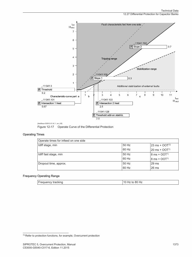
[dwdifaus-030912-01.tif, 1, en_US]
Figure 12-17 Operate Curve of the Differential Protection
Operating Times
Operate times for infeed on one sideIdiff stage, min 50 Hz
60 Hz23 ms + OOT72
20 ms + OOT1)
Idiff fast stage, min 50 Hz60 Hz
8 ms + OOT1)
8 ms + OOT1)
Dropout time, approx. 50 Hz60 Hz
29 ms26 ms
Frequency Operating Range
Frequency tracking 10 Hz to 80 Hz
72 Refer to protection functions, for example, Overcurrent protection
Technical Data12.27 Differential Protection for Capacitor Banks
SIPROTEC 5, Overcurrent Protection, Manual 1373C53000-G5040-C017-6, Edition 11.2015
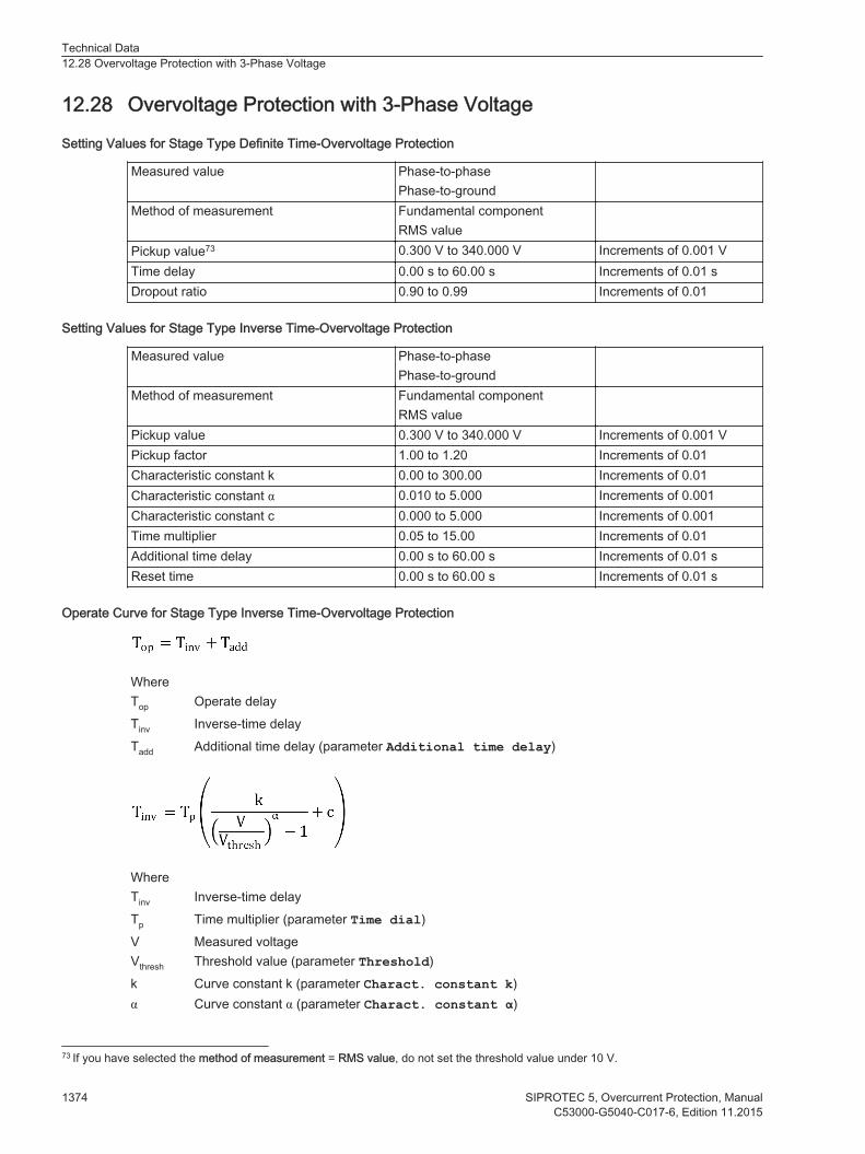
Overvoltage Protection with 3-Phase Voltage
Setting Values for Stage Type Definite Time-Overvoltage Protection
Measured value Phase-to-phasePhase-to-ground
Method of measurement Fundamental componentRMS value
Pickup value73 0.300 V to 340.000 V Increments of 0.001 VTime delay 0.00 s to 60.00 s Increments of 0.01 sDropout ratio 0.90 to 0.99 Increments of 0.01
Setting Values for Stage Type Inverse Time-Overvoltage Protection
Measured value Phase-to-phasePhase-to-ground
Method of measurement Fundamental componentRMS value
Pickup value 0.300 V to 340.000 V Increments of 0.001 VPickup factor 1.00 to 1.20 Increments of 0.01Characteristic constant k 0.00 to 300.00 Increments of 0.01Characteristic constant α 0.010 to 5.000 Increments of 0.001Characteristic constant c 0.000 to 5.000 Increments of 0.001Time multiplier 0.05 to 15.00 Increments of 0.01Additional time delay 0.00 s to 60.00 s Increments of 0.01 sReset time 0.00 s to 60.00 s Increments of 0.01 s
Operate Curve for Stage Type Inverse Time-Overvoltage Protection
WhereTop Operate delayTinv Inverse-time delayTadd Additional time delay (parameter Additional time delay)
WhereTinv Inverse-time delayTp Time multiplier (parameter Time dial)V Measured voltageVthresh Threshold value (parameter Threshold)k Curve constant k (parameter Charact. constant k)α Curve constant α (parameter Charact. constant α)
12.28
73 If you have selected the method of measurement = RMS value, do not set the threshold value under 10 V.
Technical Data12.28 Overvoltage Protection with 3-Phase Voltage
1374 SIPROTEC 5, Overcurrent Protection, ManualC53000-G5040-C017-6, Edition 11.2015
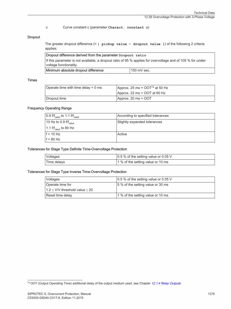
c Curve constant c (parameter Charact. constant c)
Dropout
The greater dropout difference (= | pickup value – dropout value |) of the following 2 criteriaapplies:
Dropout difference derived from the parameter Dropout ratioIf this parameter is not available, a dropout ratio of 95 % applies for overvoltage and of 105 % for under-voltage functionality.Minimum absolute dropout difference 150 mV sec.
Times
Operate time with time delay = 0 ms Approx. 25 ms + OOT74 at 50 HzApprox. 22 ms + OOT at 60 Hz
Dropout time Approx. 20 ms + OOT
Frequency Operating Range
0.9 f/frated to 1.1 f/frated According to specified tolerances
10 Hz to 0.9 f/frated
1.1 f/frated to 80 HzSlightly expanded tolerances
f < 10 Hzf > 80 Hz
Active
Tolerances for Stage Type Definite Time-Overvoltage Protection
Voltages 0.5 % of the setting value or 0.05 VTime delays 1 % of the setting value or 10 ms
Tolerances for Stage Type Inverse Time-Overvoltage Protection
Voltages 0.5 % of the setting value or 0.05 VOperate time for1.2 ≤ V/V threshold value ≤ 20
5 % of the setting value or 30 ms
Reset time delay 1 % of the setting value or 10 ms
74 OOT (Output Operating Time) additional delay of the output medium used, see Chapter 12.1.4 Relay Outputs
Technical Data12.28 Overvoltage Protection with 3-Phase Voltage
SIPROTEC 5, Overcurrent Protection, Manual 1375C53000-G5040-C017-6, Edition 11.2015
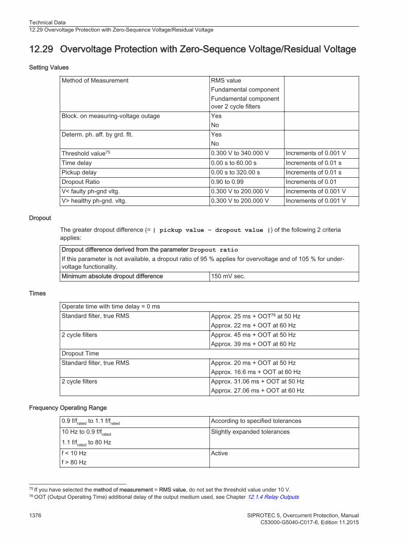
Overvoltage Protection with Zero-Sequence Voltage/Residual Voltage
Setting Values
Method of Measurement RMS valueFundamental componentFundamental componentover 2 cycle filters
Block. on measuring-voltage outage YesNo
Determ. ph. aff. by grd. flt. YesNo
Threshold value75 0.300 V to 340.000 V Increments of 0.001 VTime delay 0.00 s to 60.00 s Increments of 0.01 sPickup delay 0.00 s to 320.00 s Increments of 0.01 sDropout Ratio 0.90 to 0.99 Increments of 0.01V< faulty ph-gnd vltg. 0.300 V to 200.000 V Increments of 0.001 VV> healthy ph-gnd. vltg. 0.300 V to 200.000 V Increments of 0.001 V
Dropout
The greater dropout difference (= | pickup value – dropout value |) of the following 2 criteriaapplies:
Dropout difference derived from the parameter Dropout ratioIf this parameter is not available, a dropout ratio of 95 % applies for overvoltage and of 105 % for under-voltage functionality.Minimum absolute dropout difference 150 mV sec.
Times
Operate time with time delay = 0 msStandard filter, true RMS Approx. 25 ms + OOT76 at 50 Hz
Approx. 22 ms + OOT at 60 Hz2 cycle filters Approx. 45 ms + OOT at 50 Hz
Approx. 39 ms + OOT at 60 HzDropout TimeStandard filter, true RMS Approx. 20 ms + OOT at 50 Hz
Approx. 16.6 ms + OOT at 60 Hz2 cycle filters Approx. 31.06 ms + OOT at 50 Hz
Approx. 27.06 ms + OOT at 60 Hz
Frequency Operating Range
0.9 f/frated to 1.1 f/frated According to specified tolerances
10 Hz to 0.9 f/frated
1.1 f/frated to 80 HzSlightly expanded tolerances
f < 10 Hzf > 80 Hz
Active
12.29
75 If you have selected the method of measurement = RMS value, do not set the threshold value under 10 V.76 OOT (Output Operating Time) additional delay of the output medium used, see Chapter 12.1.4 Relay Outputs
Technical Data12.29 Overvoltage Protection with Zero-Sequence Voltage/Residual Voltage
1376 SIPROTEC 5, Overcurrent Protection, ManualC53000-G5040-C017-6, Edition 11.2015

Tolerances
Voltages 0.5 % of the setting value or 0.05 VTime delays 1 % of the setting value or 10 ms
Technical Data12.29 Overvoltage Protection with Zero-Sequence Voltage/Residual Voltage
SIPROTEC 5, Overcurrent Protection, Manual 1377C53000-G5040-C017-6, Edition 11.2015
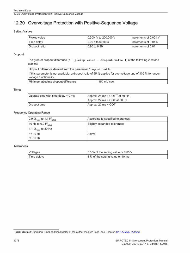
Overvoltage Protection with Positive-Sequence Voltage
Setting Values
Pickup value 0.300 V to 200.000 V Increments of 0.001 VTime delay 0.00 s to 60.00 s Increments of 0.01 sDropout ratio 0.90 to 0.99 Increments of 0.01
Dropout
The greater dropout difference (= | pickup value – dropout value |) of the following 2 criteriaapplies:
Dropout difference derived from the parameter Dropout ratioIf this parameter is not available, a dropout ratio of 95 % applies for overvoltage and of 105 % for under-voltage functionality.Minimum absolute dropout difference 150 mV sec.
Times
Operate time with time delay = 0 ms Approx. 25 ms + OOT77 at 50 HzApprox. 22 ms + OOT at 60 Hz
Dropout time Approx. 20 ms + OOT
Frequency Operating Range
0.9 f/frated to 1.1 f/frated According to specified tolerances
10 Hz to 0.9 f/frated
1.1 f/frated to 80 HzSlightly expanded tolerances
f < 10 Hzf > 80 Hz
Active
Tolerances
Voltages 0.5 % of the setting value or 0.05 VTime delays 1 % of the setting value or 10 ms
12.30
77 OOT (Output Operating Time) additional delay of the output medium used, see Chapter 12.1.4 Relay Outputs
Technical Data12.30 Overvoltage Protection with Positive-Sequence Voltage
1378 SIPROTEC 5, Overcurrent Protection, ManualC53000-G5040-C017-6, Edition 11.2015
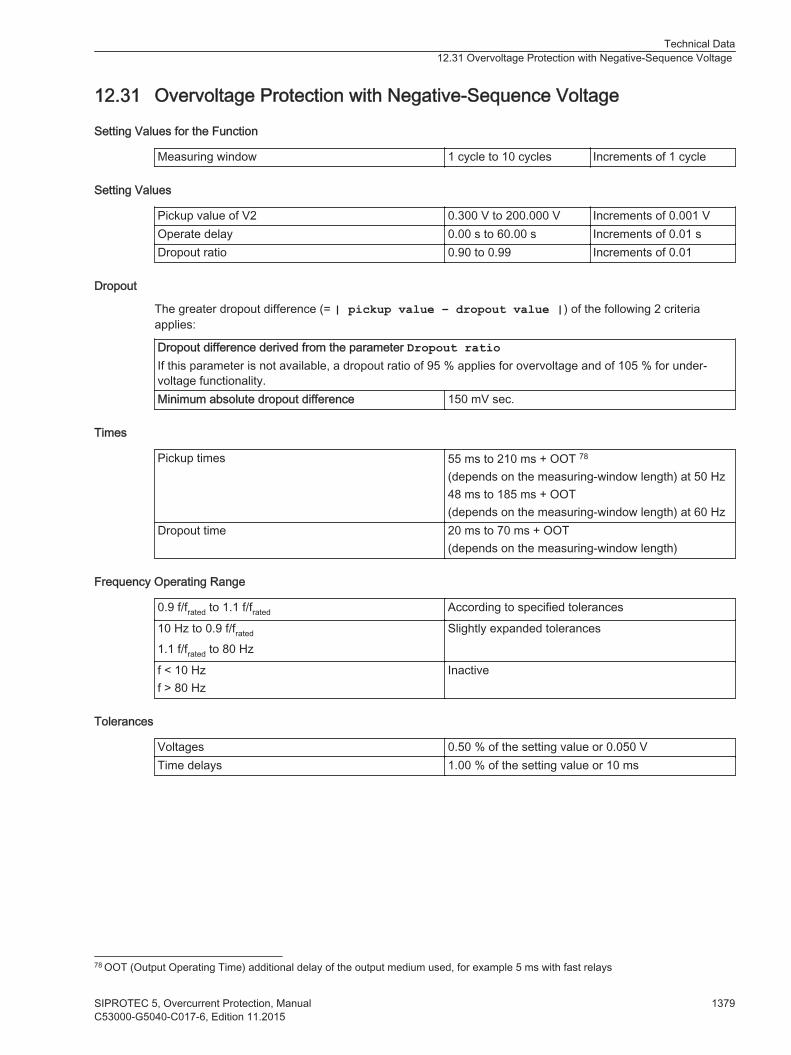
Overvoltage Protection with Negative-Sequence Voltage
Setting Values for the Function
Measuring window 1 cycle to 10 cycles Increments of 1 cycle
Setting Values
Pickup value of V2 0.300 V to 200.000 V Increments of 0.001 VOperate delay 0.00 s to 60.00 s Increments of 0.01 sDropout ratio 0.90 to 0.99 Increments of 0.01
Dropout
The greater dropout difference (= | pickup value – dropout value |) of the following 2 criteriaapplies:
Dropout difference derived from the parameter Dropout ratioIf this parameter is not available, a dropout ratio of 95 % applies for overvoltage and of 105 % for under-voltage functionality.Minimum absolute dropout difference 150 mV sec.
Times
Pickup times 55 ms to 210 ms + OOT 78
(depends on the measuring-window length) at 50 Hz48 ms to 185 ms + OOT(depends on the measuring-window length) at 60 Hz
Dropout time 20 ms to 70 ms + OOT(depends on the measuring-window length)
Frequency Operating Range
0.9 f/frated to 1.1 f/frated According to specified tolerances
10 Hz to 0.9 f/frated
1.1 f/frated to 80 HzSlightly expanded tolerances
f < 10 Hzf > 80 Hz
Inactive
Tolerances
Voltages 0.50 % of the setting value or 0.050 VTime delays 1.00 % of the setting value or 10 ms
12.31
78 OOT (Output Operating Time) additional delay of the output medium used, for example 5 ms with fast relays
Technical Data12.31 Overvoltage Protection with Negative-Sequence Voltage
SIPROTEC 5, Overcurrent Protection, Manual 1379C53000-G5040-C017-6, Edition 11.2015

Overvoltage Protection with Any Voltage
Setting Values
Measured value79 Measured phase-to-ground voltage VA
Measured phase-to-ground voltage VB
Measured phase-to-ground voltage VC
Measured phase-to-phase voltage VAB
Measured phase-to-phase voltage VBC
Measured phase-to-phase voltage VCA
Measured voltage VNMeasured phase-to-phase voltage VAB
Measured phase-to-phase voltage VBC
Measured phase-to-phase voltage VCA
Calculated voltage V0Method of measurement Fundamental component
RMS valuePickup value80 0.300 V to 340.000 V Increments of 0.001 VTime delay 0.00 s to 60.00 s Increments of 0.01 sDropout ratio 0.90 to 0.99 Increments of 0.01
Dropout
The greater dropout difference (= | pickup value – dropout value |) of the following 2 criteriaapplies:
Dropout difference derived from the parameter Dropout ratioIf this parameter is not available, a dropout ratio of 95 % applies for overvoltage and of 105 % for under-voltage functionality.Minimum absolute dropout difference 150 mV sec.
Times
Operate time with time delay =0 ms
Approx. 25 ms + OOT81 at 50 HzApprox. 22 ms + OOT at 60 Hz
Dropout time Approx. 20 ms + OOT
Frequency Operating Range
0.9 f/frated to 1.1 f/frated According to specified tolerances
10 Hz to 0.9 f/frated
1.1 f/frated to 80 HzSlightly expanded tolerances
f < 10 Hzf > 80 Hz
Active
Tolerances
Voltages 0.5 % of the setting value or 0.05 V
12.32
79 If the function Overvoltage protection with any voltage is used in a 1-phase function group, the measured-value parameter is notvisible.80 If you have selected the method of measurement = RMS value, do not set the threshold value under 10 V.81 OOT (Output Operating Time) additional delay of the output medium used, see Chapter 12.1.4 Relay Outputs
Technical Data12.32 Overvoltage Protection with Any Voltage
1380 SIPROTEC 5, Overcurrent Protection, ManualC53000-G5040-C017-6, Edition 11.2015
Time delays 1 % of the setting value or 10 ms
Technical Data12.32 Overvoltage Protection with Any Voltage
SIPROTEC 5, Overcurrent Protection, Manual 1381C53000-G5040-C017-6, Edition 11.2015
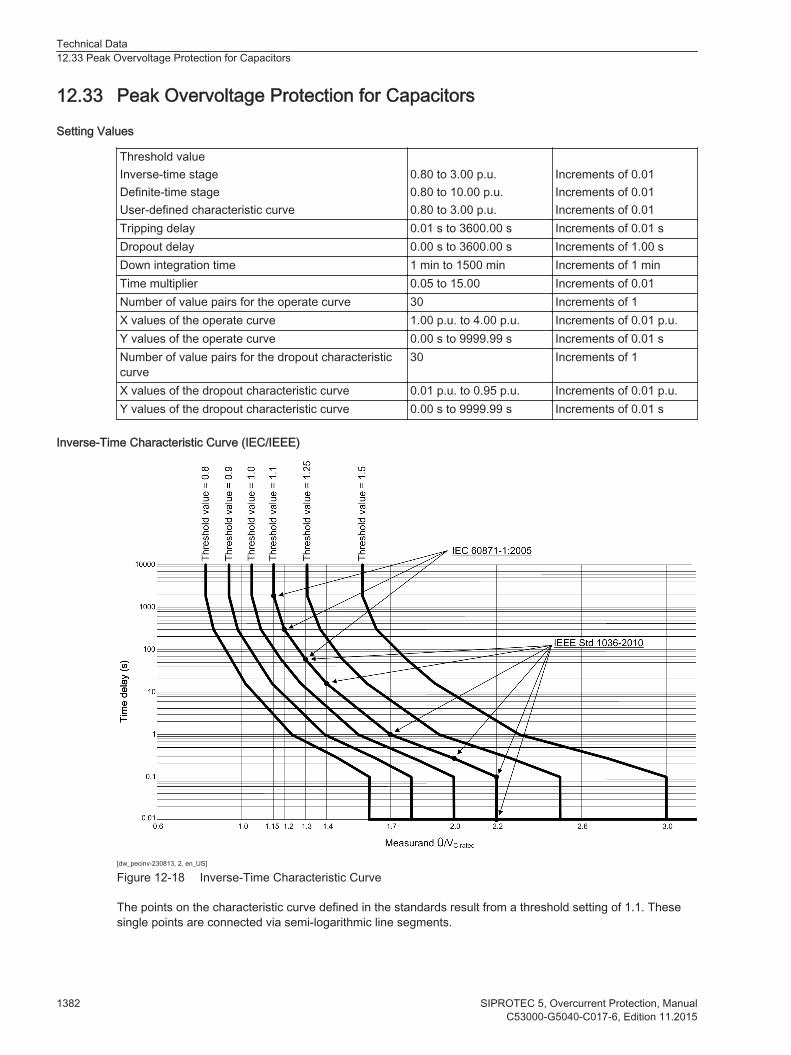
Peak Overvoltage Protection for Capacitors
Setting Values
Threshold valueInverse-time stageDefinite-time stageUser-defined characteristic curve
0.80 to 3.00 p.u.0.80 to 10.00 p.u.0.80 to 3.00 p.u.
Increments of 0.01Increments of 0.01Increments of 0.01
Tripping delay 0.01 s to 3600.00 s Increments of 0.01 sDropout delay 0.00 s to 3600.00 s Increments of 1.00 sDown integration time 1 min to 1500 min Increments of 1 minTime multiplier 0.05 to 15.00 Increments of 0.01Number of value pairs for the operate curve 30 Increments of 1X values of the operate curve 1.00 p.u. to 4.00 p.u. Increments of 0.01 p.u.Y values of the operate curve 0.00 s to 9999.99 s Increments of 0.01 sNumber of value pairs for the dropout characteristiccurve
30 Increments of 1
X values of the dropout characteristic curve 0.01 p.u. to 0.95 p.u. Increments of 0.01 p.u.Y values of the dropout characteristic curve 0.00 s to 9999.99 s Increments of 0.01 s
Inverse-Time Characteristic Curve (IEC/IEEE)
[dw_pecinv-230813, 2, en_US]
Figure 12-18 Inverse-Time Characteristic Curve
The points on the characteristic curve defined in the standards result from a threshold setting of 1.1. Thesesingle points are connected via semi-logarithmic line segments.
12.33
Technical Data12.33 Peak Overvoltage Protection for Capacitors
1382 SIPROTEC 5, Overcurrent Protection, ManualC53000-G5040-C017-6, Edition 11.2015

Table 12-7 Peak Overvoltage Inverse-Time Characteristic (for Threshold Setting 1.1)
Measurand Û/Vc,rated Time Delay Curve Point According to
<1.15 ∞ (no pickup) Siemens definition1.15 1800.00 s IEC 60871-1:20051.2 300.00 s IEC 60871-1:20051.3 60.00 s IEC 60871-1:2005, IEEE Std 1036-20101.4 15.00 s IEEE Std 1036-20101.7 1.00 s IEEE Std 1036-20102 0.25 s IEEE Std 1036-20102.2 0.1 s IEEE Std 1036-2010>2.2 0.01 s IEEE Std 1036-2010
Times
Pickup time Approx. 35 ms + OOT at 50 Hz1
Approx. 25 ms + OOT at 60 Hz1
Dropout Time Depending on settings1 OOT (Output Operating Time) additional delay of the output medium used, for example, 5 ms with fastrelays
Frequency Operating Range
0.9 f/frated to 1.1 f/frated According to specified tolerances
10 Hz to 0.9 f/frated
1.1 f/frated to 80 HzSlightly expanded tolerances
f < 10 Hzf > 80 Hz
Active
Tolerances
Peak overvoltage(33 % harmonics, with reference to fundamental component)Up to 30th harmonicUp to 50th harmonic, frated = 50 HzUp to 50th harmonic, frated = 60 Hz
1 % of the setting value or 0.005 p.u. (frated ± 10%)3 % of the setting value or 0.02 p.u. (frated ± 10%)4 % of the setting value or 0.02 p.u. (frated ± 10%)
Time delaysMeasured value of inverse-time stage 5 % of the setting value +1 % of the measured value
or 30 msMeasured value of definite-time stage 1 % of the setting value or 10 msDown integration time 5 % of the setting value or 30 ms
Technical Data12.33 Peak Overvoltage Protection for Capacitors
SIPROTEC 5, Overcurrent Protection, Manual 1383C53000-G5040-C017-6, Edition 11.2015
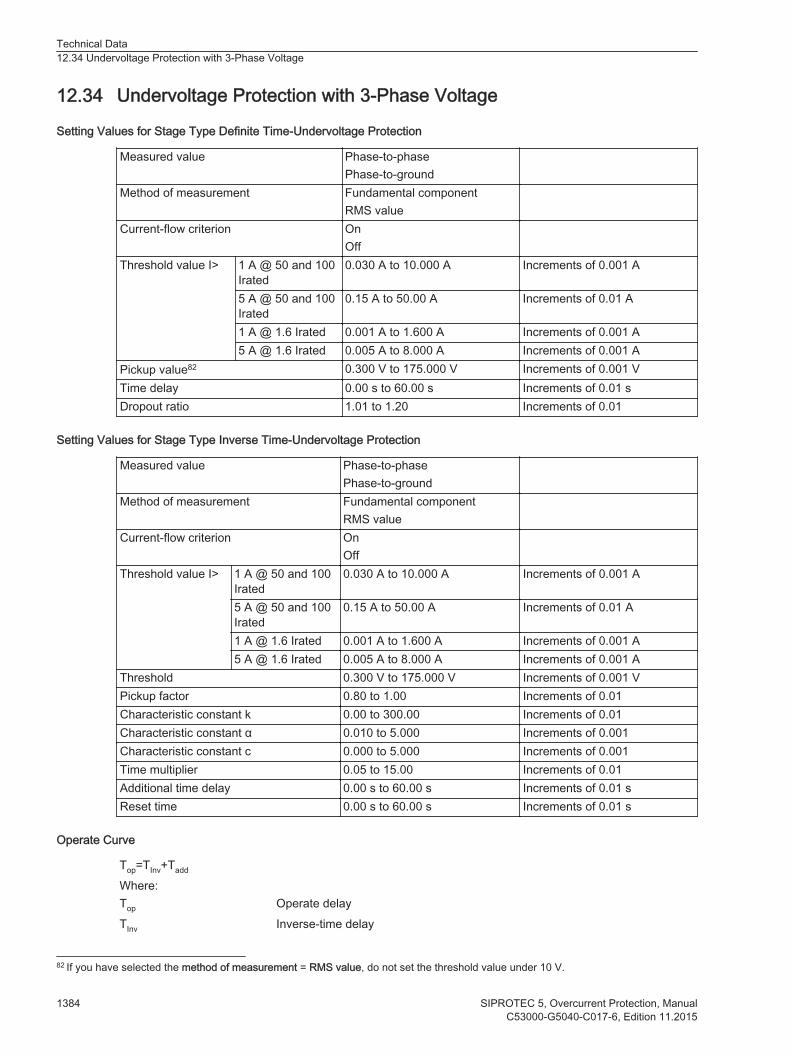
Undervoltage Protection with 3-Phase Voltage
Setting Values for Stage Type Definite Time-Undervoltage Protection
Measured value Phase-to-phasePhase-to-ground
Method of measurement Fundamental componentRMS value
Current-flow criterion OnOff
Threshold value I> 1 A @ 50 and 100Irated
0.030 A to 10.000 A Increments of 0.001 A
5 A @ 50 and 100Irated
0.15 A to 50.00 A Increments of 0.01 A
1 A @ 1.6 Irated 0.001 A to 1.600 A Increments of 0.001 A5 A @ 1.6 Irated 0.005 A to 8.000 A Increments of 0.001 A
Pickup value82 0.300 V to 175.000 V Increments of 0.001 VTime delay 0.00 s to 60.00 s Increments of 0.01 sDropout ratio 1.01 to 1.20 Increments of 0.01
Setting Values for Stage Type Inverse Time-Undervoltage Protection
Measured value Phase-to-phasePhase-to-ground
Method of measurement Fundamental componentRMS value
Current-flow criterion OnOff
Threshold value I> 1 A @ 50 and 100Irated
0.030 A to 10.000 A Increments of 0.001 A
5 A @ 50 and 100Irated
0.15 A to 50.00 A Increments of 0.01 A
1 A @ 1.6 Irated 0.001 A to 1.600 A Increments of 0.001 A5 A @ 1.6 Irated 0.005 A to 8.000 A Increments of 0.001 A
Threshold 0.300 V to 175.000 V Increments of 0.001 VPickup factor 0.80 to 1.00 Increments of 0.01 Characteristic constant k 0.00 to 300.00 Increments of 0.01 Characteristic constant α 0.010 to 5.000 Increments of 0.001 Characteristic constant c 0.000 to 5.000 Increments of 0.001 Time multiplier 0.05 to 15.00 Increments of 0.01Additional time delay 0.00 s to 60.00 s Increments of 0.01 sReset time 0.00 s to 60.00 s Increments of 0.01 s
Operate Curve
Top=TInv+Tadd
Where:Top Operate delayTInv Inverse-time delay
12.34
82 If you have selected the method of measurement = RMS value, do not set the threshold value under 10 V.
Technical Data12.34 Undervoltage Protection with 3-Phase Voltage
1384 SIPROTEC 5, Overcurrent Protection, ManualC53000-G5040-C017-6, Edition 11.2015

Tadd Additional time delay (Parameter Additional time delay)
[fo_UVP3ph_inverse, 1, en_US]
Where
TInv Inverse-time delayTp Time multiplier (Parameter Time dial)V Measured undervoltageVThresh Threshold value (Parameter Threshold)k Curve constant k (Parameter Charact. constant k)α Curve constant α (Parameter Charact. constant α)c Curve constant c (Parameter Charact. constant c)
Dropout
The greater dropout difference (= | pickup value – dropout value |) of the following 2 criteriaapplies:
Dropout difference derived from the parameter Dropout ratioIf this parameter is not available, a dropout ratio of 95 % applies for overvoltage and of 105 % for under-voltage functionality.Minimum absolute dropout difference 150 mV sec.
Times
Pickup time Approx. 25 ms + OOT83 at 50 HzApprox. 22 ms + OOT at 60 Hz
Dropout time Approx. 20 ms + OOT
Frequency Operating Range
0.9 f/frated to 1.1 f/frated According to specified tolerances
10 Hz to 0.9 f/frated
1.1 f/frated to 80 HzSlightly expanded tolerances
f < 10 Hzf > 80 Hz
Inactive, maintained;Dropout of the pickup induced by blocking or by increasing themeasurand beyond the dropout threshold
Tolerances for Stage Type Definite Time-Undervoltage Protection
Voltages 0.5 % of the setting value or 0.05 VCurrents 1 % of the setting value or 5 mA (Irated = 1 A) or 25 mA (Irated = 5
A, frated ± 10 %), valid for protection-class current transformers
1 % of the setting value or 0.1 mA (Irated = 1.6 A) or 0.5 mA (Irated
= 8 A, frated ± 10 %), valid for instrument transformers
Time delays 1 % of the setting value or 10 ms
83 OOT (Output Operating Time) additional delay of the output medium used, see Chapter 12.1.4 Relay Outputs
Technical Data12.34 Undervoltage Protection with 3-Phase Voltage
SIPROTEC 5, Overcurrent Protection, Manual 1385C53000-G5040-C017-6, Edition 11.2015
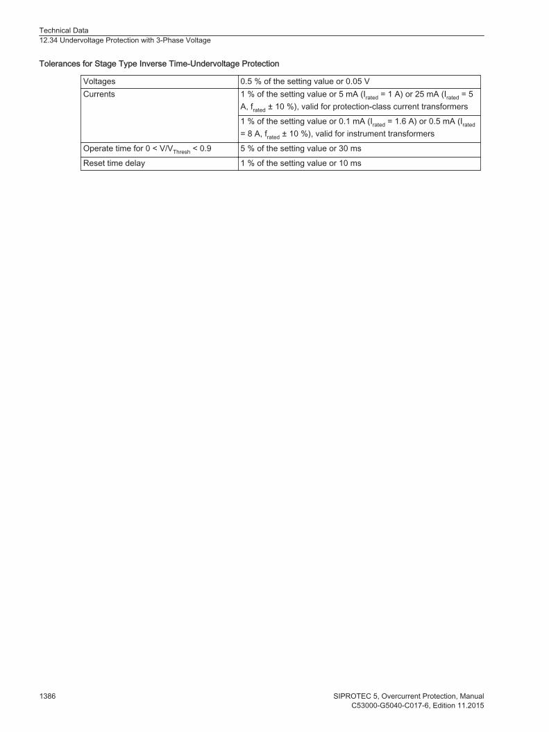
Tolerances for Stage Type Inverse Time-Undervoltage Protection
Voltages 0.5 % of the setting value or 0.05 VCurrents 1 % of the setting value or 5 mA (Irated = 1 A) or 25 mA (Irated = 5
A, frated ± 10 %), valid for protection-class current transformers
1 % of the setting value or 0.1 mA (Irated = 1.6 A) or 0.5 mA (Irated
= 8 A, frated ± 10 %), valid for instrument transformers
Operate time for 0 < V/VThresh < 0.9 5 % of the setting value or 30 ms
Reset time delay 1 % of the setting value or 10 ms
Technical Data12.34 Undervoltage Protection with 3-Phase Voltage
1386 SIPROTEC 5, Overcurrent Protection, ManualC53000-G5040-C017-6, Edition 11.2015

Undervoltage Protection with Positive-Sequence Voltage
Setting Values
Measured value Phase-to-phasePhase-to-ground
Method of measurement Fundamental componentRMS value
Current-flow criterion OnOff
Threshold value I> 1 A @ 50 and 100Irated
0.030 A to 10.000 A Increments of 0.001 A
5 A @ 50 and 100Irated
0.15 A to 50.00 A Increments of 0.01 A
1 A @ 1.6 Irated 0.001 A to 1.600 A Increments of 0.001 A5 A @ 1.6 Irated 0.005 A to 8.000 A Increments of 0.001 A
Pickup value 0.300 V to 200.000 V Increments of 0.001 VTime delay 0.00 s to 60.00 s Increments of 0.01 sDropout ratio 1.01 to 1.20 Increments of 0.01
Dropout
The greater dropout difference (= | pickup value – dropout value |) of the following 2 criteriaapplies:
Dropout difference derived from the parameter Dropout ratioIf this parameter is not available, a dropout ratio of 95 % applies for overvoltage and of 105 % for under-voltage functionality.Minimum absolute dropout difference 150 mV sec.
Times
Operate time Approx. 25 ms + OOT 84 at 50 HzApprox. 22 ms + OOT at 60 Hz
Dropout Time Approx. 20 ms + OOT
Frequency Operating Range
0.9 f/frated to 1.1 f/frated According to specified tolerances
10 Hz to 0.9 f/frated
1.1 f/frated to 80 HzSlightly expanded tolerances
f < 10 Hzf > 80 Hz
Inactive, maintained;Dropout of the pickup induced by blocking or by increasing themeasurand beyond the dropout threshold
Tolerances
Voltages 0.5 % of the setting value or 0.05 VCurrents 1 % of the setting value or 5 mA (Irated = 1 A) or 25 mA (Irated = 5 A, frated ± 10
%), valid for protection-class current transformers1 % of the setting value or 0.1 mA (Irated = 1.6 A) or 0.5 mA (Irated = 8 A, frated ±10 %), valid for instrument transformers
12.35
84 OOT (Output Operating Time) additional delay of the output medium used, see Chapter 12.1.4 Relay Outputs
Technical Data12.35 Undervoltage Protection with Positive-Sequence Voltage
SIPROTEC 5, Overcurrent Protection, Manual 1387C53000-G5040-C017-6, Edition 11.2015

Time delays 1 % of the setting value or 10 ms
Technical Data12.35 Undervoltage Protection with Positive-Sequence Voltage
1388 SIPROTEC 5, Overcurrent Protection, ManualC53000-G5040-C017-6, Edition 11.2015

Undervoltage Protection with Any Voltage
Setting Values
Measured value Measured phase-to-ground voltage VA
Measured phase-to-ground voltage VB
Measured phase-to-ground voltage VC
Measured phase-to-phase voltage VAB
Measured phase-to-phase voltage VBC
Measured phase-to-phase voltage VCA
Measured voltage VNCalculated phase-to-phase voltage VAB
Calculated phase-to-phase voltage VBC
Calculated phase-to-phase voltage VCA
Calculated voltage V0Method of measurement Fundamental component
RMS valuePickup value85 0.300 V to 340.000 V Increments of 0.001 VTime delay 0.00 s to 60.00 s Increments of 0.01 sDropout ratio 1.01 to 1.20 Increments of 0.01
Dropout
The greater dropout difference (= | pickup value – dropout value |) of the following 2 criteriaapplies:
Dropout difference derived from the parameter Dropout ratioIf this parameter is not available, a dropout ratio of 95 % applies for overvoltage and of 105 % for under-voltage functionality.Minimum absolute dropout difference 150 mV sec.
Times
Operate time with time delay = 0 ms Approx. 25 ms + OOT86 at 50 HzApprox. 22 ms + OOT at 60 Hz
Dropout time Approx. 20 ms + OOT
Frequency Operating Range
0.9 f/frated to 1.1 f/frated According to specified tolerances
10 Hz to 0.9 f/frated
1.1 f/frated to 80 HzSlightly expanded tolerances
f < 10 Hzf > 80 Hz
Inactive, maintained;Dropout of the pickup induced by blocking or by increasing themeasurand beyond the dropout threshold
Tolerances
Voltages 0.5 % of the setting value or 0.05 V
12.36
85 If you have selected the method of measurement = RMS value, do not set the threshold value under 10 V.86 OOT (Output Operating Time) additional delay of the output medium used, see chapter 12.1.4 Relay Outputs
Technical Data12.36 Undervoltage Protection with Any Voltage
SIPROTEC 5, Overcurrent Protection, Manual 1389C53000-G5040-C017-6, Edition 11.2015
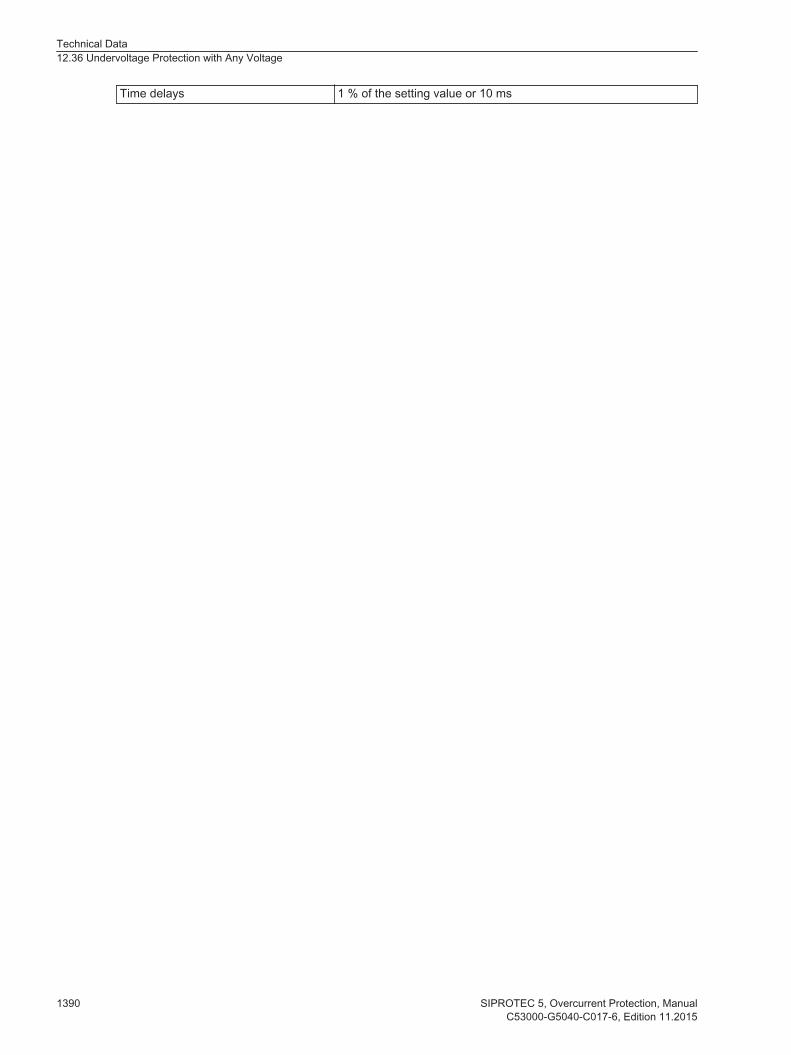
Time delays 1 % of the setting value or 10 ms
Technical Data12.36 Undervoltage Protection with Any Voltage
1390 SIPROTEC 5, Overcurrent Protection, ManualC53000-G5040-C017-6, Edition 11.2015

Overfrequency Protection
Setting Values
Pickup values f> 40.00 Hz to 70.00 Hz Increments of 0.01 HzDropout differential 20 mHz to 2 000 mHz Increments of 10 mHzTime delay T 0.00 s to 600.00 s Increments of 0.01 sMinimum voltage 3.000 V to 175.000 V Increments of 0.001 V
Times
Pickup times f> Angle difference method50 Hz60 Hz
Approx. 70 ms + OOT 87
Approx. 60 ms + OOTFiltering method50 Hz60 Hz
Approx. 75 ms + OOTApprox. 75 ms + OOT
Dropout times f> 60 ms to 80 ms
Dropout Ratio
Minimum voltage About 1.05
Operating Ranges
Voltage range 5 V to 230 V (phase-phase)Frequency range Angle difference method 10 Hz to 80 Hz
Filtering method 25 Hz to 80 Hz
Tolerances
Frequency f>frated - 0.20 Hz < f < frated + 0.20 Hz ± 5 mHz at V = Vrated
frated - 3.0 Hz < f < frated + 3.0 Hz ± 10 mHz at V = Vrated
Time delay T(f>) 1 % of the setting value or 10 msMinimum voltage 1 % of the setting value or 0.5 V
12.37
87 OOT (Output Operating Time) additional delay of the output medium used, for example 5 ms with fast relays, see chapter12.1.4 Relay Outputs
Technical Data12.37 Overfrequency Protection
SIPROTEC 5, Overcurrent Protection, Manual 1391C53000-G5040-C017-6, Edition 11.2015

Underfrequency Protection
Setting Values
Pickup values f< 40.00 Hz to 70.00 Hz Increments of 0.01 HzDropout differential 20 mHz to 2 000 mHz Increments of 10 mHzTime delay T 0.00 s to 600.00 s Increments of 0.01 sMinimum voltage 3.000 V to 175.000 V Increments of 0.001 V
Times
Pickup times f< Angle difference method50 Hz60 Hz
Approx. 70 ms + OOT 88
Approx. 60 ms + OOTFiltering method50 Hz60 Hz
Approx. 75 ms + OOTApprox. 75 ms + OOT
Dropout times f< 60 ms to 80 ms
Dropout Ratio
Minimum voltage Approx. 1.05
Operating Ranges
Voltage range 5 V to 230 V (phase-phase)Frequency range Angle difference method 10 Hz to 80 Hz
Filtering method 25 Hz to 80 Hz
Tolerances
Frequency f<frated - 0.20 Hz < f < frated + 0.20 Hz ± 5 mHz at V = Vrated
frated - 3.0 Hz < f < frated + 3.0 Hz ± 10 mHz at V = Vrated
Time delay T(f<) 1 % of the setting value or 10 msMinimum voltage 1 % of the setting value or 0.5 V
12.38
88 OOT (Output Operating Time) additional delay of the output medium used, for example 5 ms with fast relays, see chapter12.1.4 Relay Outputs
Technical Data12.38 Underfrequency Protection
1392 SIPROTEC 5, Overcurrent Protection, ManualC53000-G5040-C017-6, Edition 11.2015
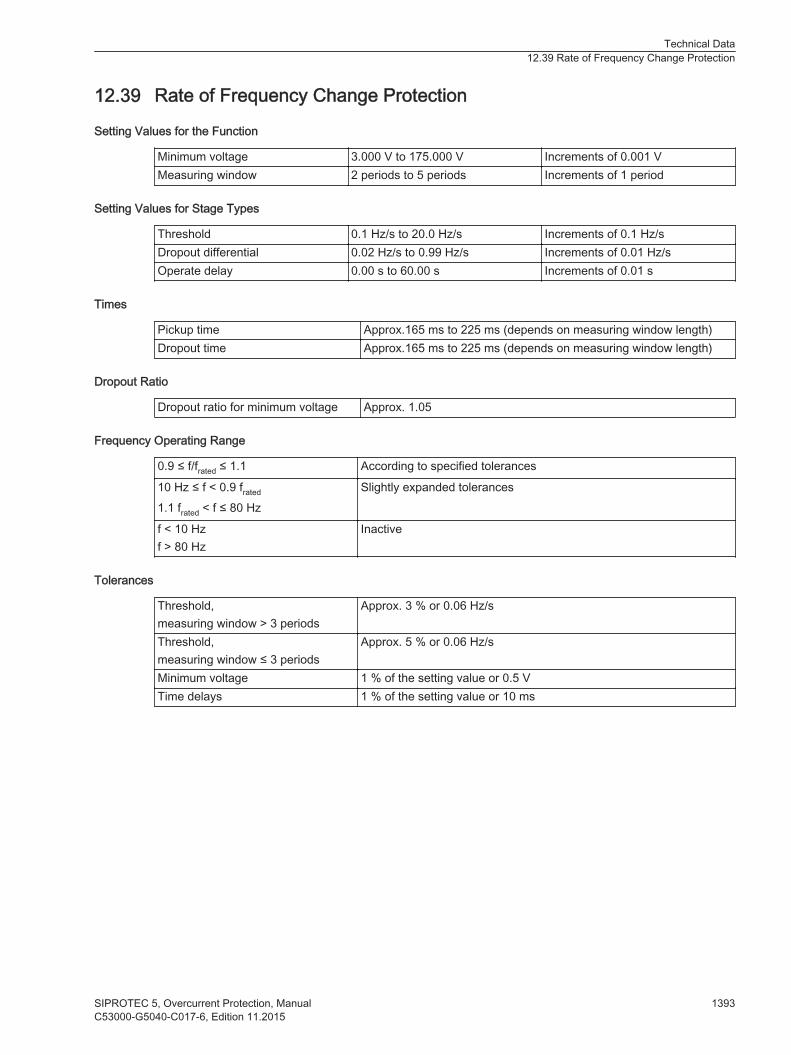
Rate of Frequency Change Protection
Setting Values for the Function
Minimum voltage 3.000 V to 175.000 V Increments of 0.001 VMeasuring window 2 periods to 5 periods Increments of 1 period
Setting Values for Stage Types
Threshold 0.1 Hz/s to 20.0 Hz/s Increments of 0.1 Hz/sDropout differential 0.02 Hz/s to 0.99 Hz/s Increments of 0.01 Hz/sOperate delay 0.00 s to 60.00 s Increments of 0.01 s
Times
Pickup time Approx.165 ms to 225 ms (depends on measuring window length)Dropout time Approx.165 ms to 225 ms (depends on measuring window length)
Dropout Ratio
Dropout ratio for minimum voltage Approx. 1.05
Frequency Operating Range
0.9 ≤ f/frated ≤ 1.1 According to specified tolerances
10 Hz ≤ f < 0.9 frated
1.1 frated < f ≤ 80 HzSlightly expanded tolerances
f < 10 Hzf > 80 Hz
Inactive
Tolerances
Threshold,measuring window > 3 periods
Approx. 3 % or 0.06 Hz/s
Threshold,measuring window ≤ 3 periods
Approx. 5 % or 0.06 Hz/s
Minimum voltage 1 % of the setting value or 0.5 VTime delays 1 % of the setting value or 10 ms
12.39
Technical Data12.39 Rate of Frequency Change Protection
SIPROTEC 5, Overcurrent Protection, Manual 1393C53000-G5040-C017-6, Edition 11.2015

3-Phase Power Protection (P,Q)
Setting Values
Measured value Positive sequence powerPower of phase APower of phase BPower of phase C
Threshold value -200.0 % to +200.0 % Increments of 0.1Tilt-power characteristic -89.0° to +89.0° Increments of 0.1°Dropout delay time 0.00 s to 60.00 s Increments of 0.01 sTime delay 0.00 s to 60.00 s Increments of 0.01 sDropout ratio Upper stage: 0.90 to 0.99
Lower stage: 1.01 to 1.10Increments of 0.01Increments of 0.01
Times
Pickup times Approx. 55 ms + OOT89 at 50 HzApprox. 45 ms + OOT at 60 Hz
Dropout times Approx. 55 ms + OOT at 50-HzApprox. 45 ms + OOT at 60 Hz
Tolerances
Power 0.5 % Srated ± 3 % of setting value(Srated: rated apparent power)
Time delays 1 % of the setting value or 10 ms
Variables That Influence Pickup Values
Auxiliary DC voltage in the range 0.8 ≤ VAux/VAuxRated ≤ 1.15 ≤ 1 %
Frequency in the range 0.95 ≤ f/frated ≤ 1.05 ≤ 1 %
Harmonics- Up to 10 % of 3rd harmonics- Up to 10 % of 5th harmonics
≤ 1 %≤ 1 %
12.40
89 OOT (Output Operating Time) additional delay of the output medium used, see Chapter 12.1.4 Relay Outputs
Technical Data12.40 3-Phase Power Protection (P,Q)
1394 SIPROTEC 5, Overcurrent Protection, ManualC53000-G5040-C017-6, Edition 11.2015

Reverse-Power Protection
Setting Values
Reverse power Preverse (p.u.) -0.30 % to -30.00 % Increments of 0.01 %
Tripping delay 0.00 s to 60.00 s Increments of 0.01 sDropout ratio 0.40 to 0.99 Increments of 0.01
Times
Pickup times Approx. 360 ms at f = 50 HzApprox. 300 ms at f = 60 Hz
Dropout times Approx. 360 ms at f = 50 HzApprox. 300 ms at f = 60 Hz
Frequency Operating Range
0.9 f/frated to 1.1 f/frated According to specified tolerances
10 Hz to 0.9 f/frated
1.1 f/frated to 80 HzSlightly expanded tolerances
f < 10 Hzf > 80 Hz
Inactive
Tolerances
Reverse power 0.15 % Srated or 5 % of the setting value when Q < 0.5 Srated
Time delays 1 % or 10 ms
12.41
Technical Data12.41 Reverse-Power Protection
SIPROTEC 5, Overcurrent Protection, Manual 1395C53000-G5040-C017-6, Edition 11.2015

Overexcitation Protection
Setting Values
Threshold value(Characteristic curve dependent onpickup)
1.00 to 1.20 Increments of 0.01
Threshold value(Characteristic curve independent onpickup)
1.00 to 1.40 Increments of 0.01
Time delay (warning delay and tripping delay) 0.00 s to 60.00 s Increments of 0.01 sCharacteristic value pairs 2 to 30
Value ranges V/Hz 1 p.u. to 10 p.u. Increments of 0.01p.u.
t 0 s to 100 000 s Increments of 1 sCooling time therm. replica 0 s to 100 000 s Increments of 1 s
Frequency Operating Range
Frequency tracking 10 Hz to 80 Hz
Operating Times
Operate times/dropout timesOperate time at frequency 50 Hz 60 HzMinimum 33 ms + OOT1 30 ms + OOT90
Dropout time 10 ms + OOT1 10 ms + OOT1
Dropout Ratios
Warning, tripping (independent stage) Approx. 0.98
Operate Curve
Thermal replica For default setting refer to the followingcharacteristic curve Figure 12-19
Tolerances
V/Hz pickup 2 % of the setting valueTime delays 1 % of the setting value or 10 ms (min. of
1.5 cycles)Thermal replica 5 % based on V/Hz ± 600 msMeasurement accuracy of voltage 0.5 % of the setting value or 0.5 V in the
range fn ± 10 %)Measurement accuracy of frequency 1.0 % of the setting value or 1.0 Hz in the
frequency range 10 Hz to 80 Hz
Influencing Quantities
Auxiliary direct voltage in the 0.8 range ≤ 1 %Time delays ≤ 0.5 %/10 KThermal replica ≤ 1 %
12.42
90 Refer to protection functions, for example overcurrent protection
Technical Data12.42 Overexcitation Protection
1396 SIPROTEC 5, Overcurrent Protection, ManualC53000-G5040-C017-6, Edition 11.2015

Harmonicsup to 10 % of 3rd harmonicsup to 10 % of 5th harmonics
≤ 1 %≤ 1 %
[dwrsasuf-070513-01.tif, 1, en_US]
Figure 12-19 Operate Curve from the Thermal Replica of the Overexcitation Protection (Default Setting)
Technical Data12.42 Overexcitation Protection
SIPROTEC 5, Overcurrent Protection, Manual 1397C53000-G5040-C017-6, Edition 11.2015

Undervoltage-Controlled Reactive-Power Protection
Setting Values
Threshold value Power Q 1.00 % to 200.00 % Increments of 0.01 %Voltage of protectionstage
3.000 to 175.000 Increments of 0.001 V
Voltage of reclosurestage
3.000 V to 340.000 V Increments of 0.001 V
Current I1 release threshold 1 A @ 50 and 100 Irated 0.030 A to 10.000 A Increments of 0.001 A5 A @ 50 and 100 Irated 0.15 A to 50.00 A Increments of 0.01 A1 A @ 1.6 Irated 0.001 A to 1.600 A Increments of 0.001 A5 A @ 1.6 Irated 0.005 A to 8.000 A Increments of 0.001 A
Operate delay 0.00 s to 60.00 s Increments of 0.01 sRelease time delay of reclosure stage 0.00 s to 3600.00 s Increments of 0.01 s
Dropout Ratio
Protection stageReactive-power flow Q Approx. 0.95Voltage Approx. 1.05Release current Approx. 0.95
Reclosure stageVoltage Approx. 0.95Release current Approx. 0.95
Times
Pickup time Approx. 55 ms + OOT91 at 50 HzApprox. 45 ms + OOT at 60 Hz
Dropout time Approx. 55 ms + OOT at 50 HzApprox. 45 ms + OOT at 60 Hz
Tolerances
Current I1 1 % of the setting value or 5 mA (Irated = 1 A)or 25 mA (Irated = 5 A)
Voltage 0.5 % of the setting value or 0.05 VPower Q 0.5 % Srated ± 3 % of the setting value
(Srated: rated apparent power)
Time delays 1 % of the setting value or 10 msReclosure time delay 1 % of the setting value or 10 ms
Frequency Operating Range
0.9 ≤ f/frated ≤ 1.1 According to specified tolerances
10 Hz ≤ f < 0.9 frated
1.1 frated < f ≤ 80 HzSlightly expanded tolerances
12.43
91 OOT (Output Operating Time) additional delay of the output medium used, for example 5 ms with fast relays
Technical Data12.43 Undervoltage-Controlled Reactive-Power Protection
1398 SIPROTEC 5, Overcurrent Protection, ManualC53000-G5040-C017-6, Edition 11.2015

f < 10 Hzf > 80 Hz
Function is blocked
Technical Data12.43 Undervoltage-Controlled Reactive-Power Protection
SIPROTEC 5, Overcurrent Protection, Manual 1399C53000-G5040-C017-6, Edition 11.2015

Circuit-Breaker Failure Protection
Starting Conditions
For circuit-breaker failure protection 3-pole internal or external tripping92
Setting Values
Phase-current thresholdvalues
1 A @ 100 Irated 0.030 A to 35.000 A Increments of 0.001 A1 A @ 50 Irated5 A @ 100 Irated 0.15 A to 175.00 A Increments of 0.01 A5 A @ 50 Irated1 A @ 1.6 Irated 0.001 A to 1.600 A Increments of 0.001 A5 A @ 1.6 Irated 0.005 A to 8.000 A Increments of 0.001 A
Ground-current thresholdvalue
1 A @ 100 Irated 0.030 A to 35.000 A Increments of 0.001 A1 A @ 50 Irated5 A @ 100 Irated 0.15 A to 175.00A Increments of 0.01 A5 A @ 50 Irated1 A @ 1.6 Irated 0.001 A to 1.600 A Increments of 0.001 A5 A @ 1.6 Irated 0.005 A to 8.000 A Increments of 0.001 A
Supervision time of release signal 0.06 s to 1.00 s Increments of 0.01 sTime delays 0.05 s to 60.00 s Increments of 0.01 s
Dropout Ratios
Current threshold values Approx. 0.95
Circuit-Breaker Supervision
Position supervision of circuit-breaker auxiliary contactsFor 3-pole CB tripping 1 input each for make contact and break contact
iiNOTE
The circuit-breaker failure protection can also work without the circuit-breaker auxiliary contacts stated.Auxiliary contacts are required for circuit-breaker failure protection in cases where the current flow isabsent or too low for tripping (for example with a transformer or a Buchholz protection).
Times
Pickup time, in the case of an internal startPickup time, in the case of an external start
< 1 ms< 5 ms
Dropout time93 via the current-flow criterion, for sinus-oidal quantities
< 10 ms
Dropout time, via the current-flow criterion, under allconditions
< 15 ms
Dropout time, via circuit-breaker auxiliary-contactcriterion
< 5 ms
12.44
92 Via binary inputs93 The dropout time is the time required by the CBFP function to detect that the CB is open. The time for mechanically switching acontact is not included.
Technical Data12.44 Circuit-Breaker Failure Protection
1400 SIPROTEC 5, Overcurrent Protection, ManualC53000-G5040-C017-6, Edition 11.2015
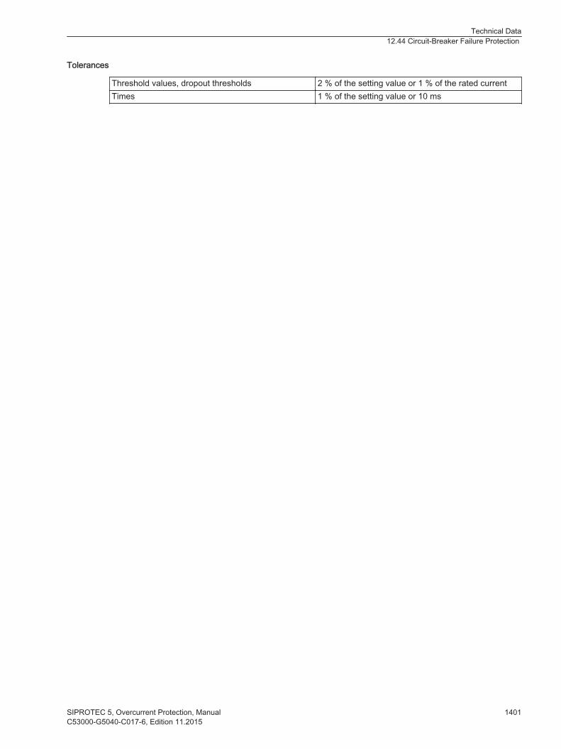
Tolerances
Threshold values, dropout thresholds 2 % of the setting value or 1 % of the rated currentTimes 1 % of the setting value or 10 ms
Technical Data12.44 Circuit-Breaker Failure Protection
SIPROTEC 5, Overcurrent Protection, Manual 1401C53000-G5040-C017-6, Edition 11.2015
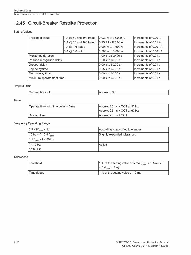
Circuit-Breaker Restrike Protection
Setting Values
Threshold value 1 A @ 50 and 100 Irated 0.030 A to 35.000 A Increments of 0.001 A5 A @ 50 and 100 Irated 0.15 A to 175.00 A Increments of 0.01 A1 A @ 1.6 Irated 0.001 A to 1.600 A Increments of 0.001 A5 A @ 1.6 Irated 0.005 A to 8.000 A Increments of 0.001 A
Monitoring duration 1.00 s to 600.00 s Increments of 0.01 sPosition recognition delay 0.00 s to 60.00 s Increments of 0.01 sDropout delay 0.00 s to 60.00 s Increments of 0.01 sTrip delay time 0.05 s to 60.00 s Increments of 0.01 sRetrip delay time 0.00 s to 60.00 s Increments of 0.01 sMinimum operate (trip) time 0.00 s to 60.00 s Increments of 0.01 s
Dropout Ratio
Current threshold Approx. 0.95
Times
Operate time with time delay = 0 ms Approx. 25 ms + OOT at 50 HzApprox. 22 ms + OOT at 60 Hz
Dropout time Approx. 20 ms + OOT
Frequency Operating Range
0.9 ≤ f/frated ≤ 1.1 According to specified tolerances
10 Hz ≤ f < 0.9 frated
1.1 frated < f ≤ 80 HzSlightly expanded tolerances
f < 10 Hzf > 80 Hz
Active
Tolerances
Threshold 1 % of the setting value or 5 mA (Irated = 1 A) or 25mA (Irated = 5 A)
Time delays 1 % of the setting value or 10 ms
12.45
Technical Data12.45 Circuit-Breaker Restrike Protection
1402 SIPROTEC 5, Overcurrent Protection, ManualC53000-G5040-C017-6, Edition 11.2015

Restricted Ground-Fault Protection
Setting Values
Threshold value94 0.05 A to 2.00 A Increments of 0.01A
Gradient 0.00 to 0.95 Increments of 0.01Operate curve See figurePickup tolerance(for preset characteristic curve settings; for 2 sides with 1 meas-uring point each)
2 %
Tripping delay 0.00 s to 60.00 s or∞ (no tripping)
Increments of 0.01 s
Timer tolerance 1 % of the setting value or 10 ms
Dropout Ratio
Threshold value 0.7
Times
7UT82/7UT85/7UT86/7UT87Frequency 50 Hz 60 Hz
Operate time Operate timeAt 1,5 · setting value threshold valueAt 2.5 · setting value threshold value
33 ms + OOT27 ms + OOT
32 ms + OOT26 ms + OOT
Dropout time approx. 80 ms 67 msDropout ratio 0.7
12.46
94 The specified setting limit can be dynamically further limited, depending on the transformer adaptation factor, (for this refer to Chapter6.39.4 Application and Setting Notes ).
Technical Data12.46 Restricted Ground-Fault Protection
SIPROTEC 5, Overcurrent Protection, Manual 1403C53000-G5040-C017-6, Edition 11.2015

[dwausken-170712-01.tif, 1, en_US]
Figure 12-20 Operate Curve of the Restricted Ground-Fault Protection Depending on the Phase AngleBetween I 0* and I 0** at |I 0*| = |I 0**| (180° = External Fault)
Technical Data12.46 Restricted Ground-Fault Protection
1404 SIPROTEC 5, Overcurrent Protection, ManualC53000-G5040-C017-6, Edition 11.2015
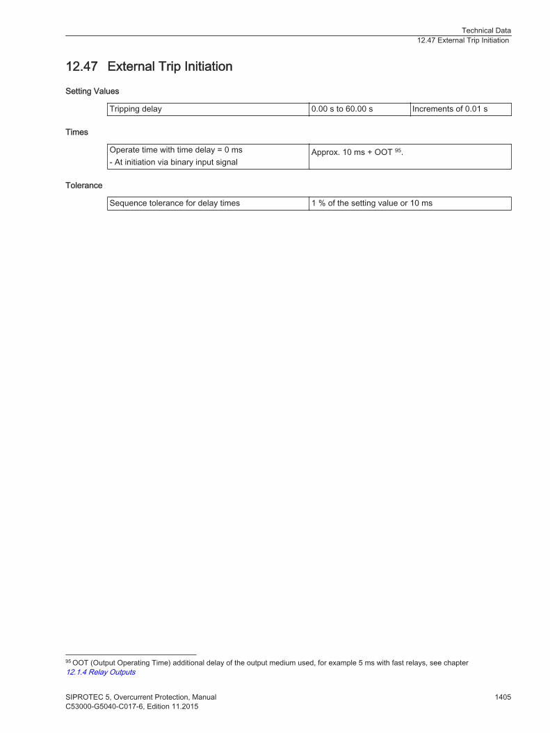
External Trip Initiation
Setting Values
Tripping delay 0.00 s to 60.00 s Increments of 0.01 s
Times
Operate time with time delay = 0 ms- At initiation via binary input signal
Approx. 10 ms + OOT 95.
Tolerance
Sequence tolerance for delay times 1 % of the setting value or 10 ms
12.47
95 OOT (Output Operating Time) additional delay of the output medium used, for example 5 ms with fast relays, see chapter12.1.4 Relay Outputs
Technical Data12.47 External Trip Initiation
SIPROTEC 5, Overcurrent Protection, Manual 1405C53000-G5040-C017-6, Edition 11.2015
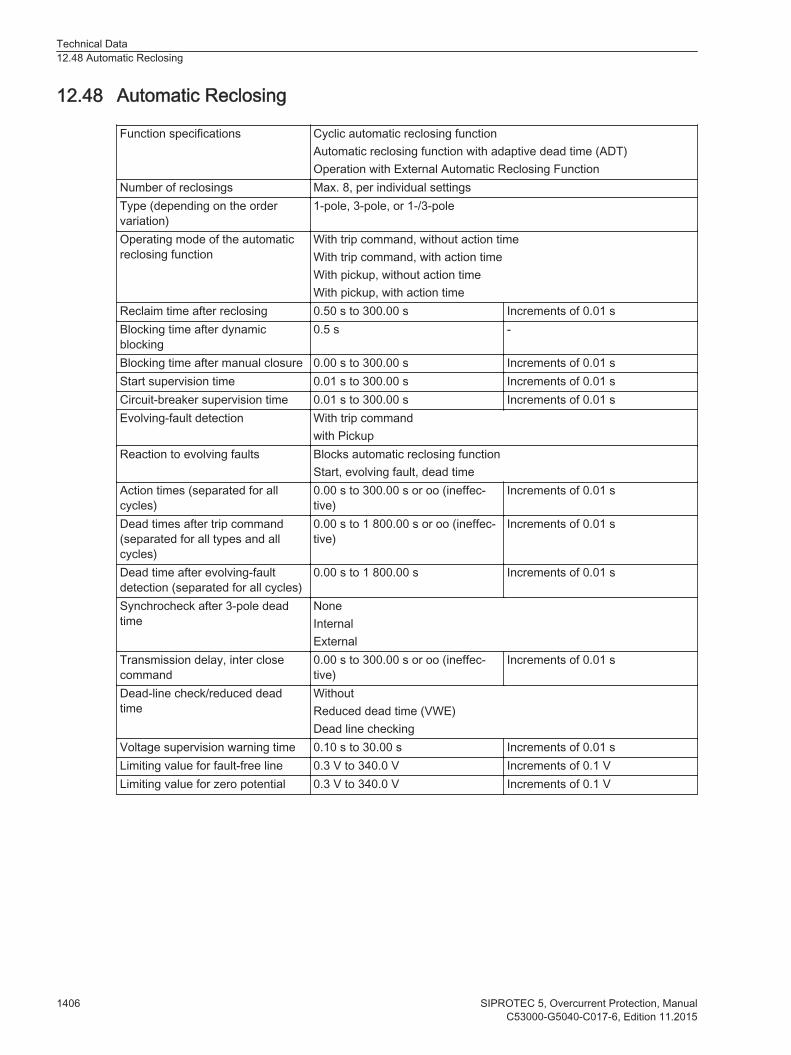
Automatic Reclosing
Function specifications Cyclic automatic reclosing functionAutomatic reclosing function with adaptive dead time (ADT)Operation with External Automatic Reclosing Function
Number of reclosings Max. 8, per individual settingsType (depending on the ordervariation)
1-pole, 3-pole, or 1-/3-pole
Operating mode of the automaticreclosing function
With trip command, without action timeWith trip command, with action timeWith pickup, without action timeWith pickup, with action time
Reclaim time after reclosing 0.50 s to 300.00 s Increments of 0.01 sBlocking time after dynamicblocking
0.5 s -
Blocking time after manual closure 0.00 s to 300.00 s Increments of 0.01 sStart supervision time 0.01 s to 300.00 s Increments of 0.01 sCircuit-breaker supervision time 0.01 s to 300.00 s Increments of 0.01 sEvolving-fault detection With trip command
with PickupReaction to evolving faults Blocks automatic reclosing function
Start, evolving fault, dead timeAction times (separated for allcycles)
0.00 s to 300.00 s or oo (ineffec-tive)
Increments of 0.01 s
Dead times after trip command(separated for all types and allcycles)
0.00 s to 1 800.00 s or oo (ineffec-tive)
Increments of 0.01 s
Dead time after evolving-faultdetection (separated for all cycles)
0.00 s to 1 800.00 s Increments of 0.01 s
Synchrocheck after 3-pole deadtime
NoneInternalExternal
Transmission delay, inter closecommand
0.00 s to 300.00 s or oo (ineffec-tive)
Increments of 0.01 s
Dead-line check/reduced deadtime
WithoutReduced dead time (VWE)Dead line checking
Voltage supervision warning time 0.10 s to 30.00 s Increments of 0.01 sLimiting value for fault-free line 0.3 V to 340.0 V Increments of 0.1 VLimiting value for zero potential 0.3 V to 340.0 V Increments of 0.1 V
12.48
Technical Data12.48 Automatic Reclosing
1406 SIPROTEC 5, Overcurrent Protection, ManualC53000-G5040-C017-6, Edition 11.2015

Fault Locator
Setting Values
Reactance per unit length of the line per kilometer or per mileLine length for the correct output of the fault distance as a percentage of the line lengthThe residual compensation factors in the setting format Kr and Kx or K0 and angle (K0)Consideration of the load current for 1-pole groundfaults
Correction of the X value, for connection and discon-nection
Fault Distance
Output of the fault distance (line length) In Ω primary and secondaryIn km, miles or in percent. 96
Tolerances
Measuring tolerances during sinusoidal measurandsand error duration> 25 ms at 60 Hz or> 30 ms at 50 Hz
1.5 % from fault location at VK/Vrated ≥ 0.01 and oneof the following scenarios:• Metal fault• Non-metallic fault for one-side infeed without
load
12.49
96 The output of the fault distance in km, miles and percent presupposes a homogenous line.
Technical Data12.49 Fault Locator
SIPROTEC 5, Overcurrent Protection, Manual 1407C53000-G5040-C017-6, Edition 11.2015

Temperature Supervision
Setting Values
Pickup value -50 °C to 250 °C-58 °F to 482 °F
Increments of 1°CIncrements of 1°F
Time delay 0 s to 60 sor ∞
Increments of 1 s
Dropout Conditions
Dropout differential 3 °C or 6 °F
Tolerances
Tripping delay ±1 % of the setting value or ±10 msMeasured temperature value ±0.5 % of the setting value or ±1 °C or ±2 °F
12.50
Technical Data12.50 Temperature Supervision
1408 SIPROTEC 5, Overcurrent Protection, ManualC53000-G5040-C017-6, Edition 11.2015

Current-Jump Detection
Times
Pickup time Approx. 10 ms + OOT97 at 50 HzApprox. 8 ms + OOT at 60 Hz
Operating Range
10 Hz to 80 Hz Function activeBehavior outside the operating range Function inactive
Tolerances
Currents 3 % of setting value or 10 mA (Irated = 1 A) or50 mA (Irated = 5 A), (frated ± 10 %)for amplitude changes of sinusoidal measurands
Pulse time 1 % of the setting value or 10 ms
12.51
97 OOT (Output Operating Time) additional delay of the output medium used, for example 5 ms with fast relays
Technical Data12.51 Current-Jump Detection
SIPROTEC 5, Overcurrent Protection, Manual 1409C53000-G5040-C017-6, Edition 11.2015
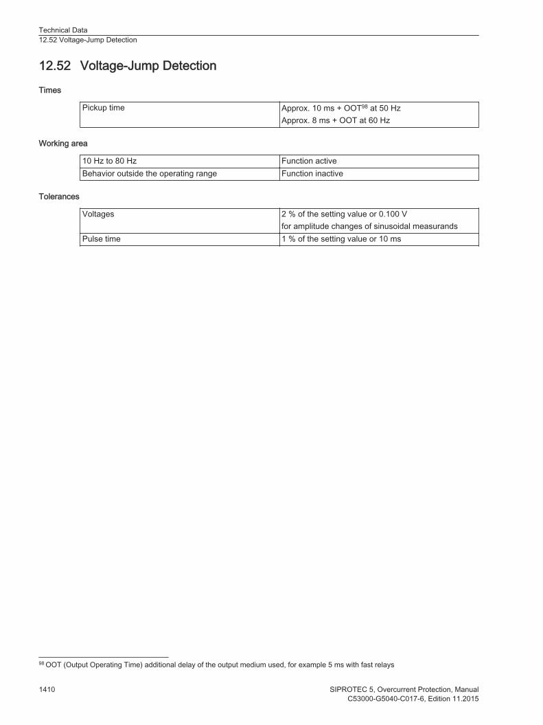
Voltage-Jump Detection
Times
Pickup time Approx. 10 ms + OOT98 at 50 HzApprox. 8 ms + OOT at 60 Hz
Working area
10 Hz to 80 Hz Function activeBehavior outside the operating range Function inactive
Tolerances
Voltages 2 % of the setting value or 0.100 Vfor amplitude changes of sinusoidal measurands
Pulse time 1 % of the setting value or 10 ms
12.52
98 OOT (Output Operating Time) additional delay of the output medium used, for example 5 ms with fast relays
Technical Data12.52 Voltage-Jump Detection
1410 SIPROTEC 5, Overcurrent Protection, ManualC53000-G5040-C017-6, Edition 11.2015

Synchronization Function
Operating Modes
SynchrocheckSwitching synchronous systemsSwitching asynchronous systemsDe-energized switchingDirect closing command
Setting Values
Supervision/Delay times:Max. Duration of synchronizationprocess
0.00 s to 3 600.00 s or ∞ (ineffec-tive)
Increments of 0.01 s
Supervision time de-energizedswitching
0.00 s to 60.00 s Increments of 0.01 s
Closure delay 0.00 s to 60.00 s Increments of 0.01 sVoltage threshold values:Upper voltage limit Vmax 0.300 V to 340.000 V (phase-to-
phase)Increments of 0.001 V
Lower voltage limit Vmin 0.300 V to 340.000 V (phase-to-phase)
Increments of 0.001 V
V<, for off-circuit conditionsV>, for voltage present
0.300 V to 170.000 V (phase-to-phase)0.300 V to 340.000 V (phase-to-phase)
Increments of 0.001 VIncrements of 0.001 V
Differential values, changeover thresholds asynchronous/synchronous:Voltage differencesV2 > V1; V2 < V1
0.000 V to 170.000 V Increments of 0.001 V
Frequency difference f2 > f1;f2 < f1
0.000 Hz to 2.000 Hz (synchro-nous)0.000 Hz to 4.000 Hz (asynchro-nous)
Increments of 0.001 Hz
Angular difference α2 > α1;α2 < α1
0o to 90o Increments of 1o
Δf threshold ASYN <-> SYN 0.010 Hz to 0.200 Hz Increments of 0.001 HzAdjustments of the sides:Angle adjustment 0.0o to 360.0o Increments of 0.1o
Voltage adjustment 0.500 to 2.000 Increments of 0.001Circuit breakerClosing time of the circuit breaker 0.01 s to 0.60 s Increments of 0.01 s
Dropout Ratio
Min./max. operating limit 1 % of the setting valueVoltage differential 10 % of the setting value or 0.5 VDe-energized/energized 5 % of the setting valueFrequency difference 3 mHzAngular difference 0.1o
12.53
Technical Data12.53 Synchronization Function
SIPROTEC 5, Overcurrent Protection, Manual 1411C53000-G5040-C017-6, Edition 11.2015

Measured Values of the Synchronization Function
Reference voltage V1 • Range• Tolerance at rated frequency
In kV primary, in V secondary or in % Vrated
Display always as phase-to-phase voltage10 % to 120 % of Vrated
≤ 1% of the measured value or 0.5% Vrated
Voltage to be synchronized V2 • Range• Tolerance at rated frequency
In kV primary, in V secondary or in % Vrated
Display always as phase-to-phase voltage10 % to 120 % of Vrated
≤ 1% of the measured value or 0.5% Vrated
Frequency of the voltage V1f1• Range• Tolerance at rated frequency
f1 in Hz25 Hz ≤ f ≤ 70 Hz1 mHz
Frequency of the voltage V1f2• Range• Tolerance at rated frequency
f2 in Hz25 Hz ≤ f ≤ 70 Hz1 mHz
Voltage difference V2-V1 • Range• Tolerance at rated frequency
In kV primary, in V secondary or in % Vrated
Display always as phase-to-phase voltage in relationto side 110 % to 120 % of Vrated
≤ 1% of the measured value or 0.5% Vrated
Frequency difference f2-f1• Range• Tolerance at rated frequency
In mHzfrated ± 10 %1 mHz
Angular difference λ2-λ1• Range• Tolerance at rated frequency
In o
-180o to +180o
0.5o
Times
Measuring time, after switching on the variables Approx. 80 ms
Operating Range
Voltage 20 V to 340 VFrequency frated -4 Hz ≤ frated ≤ frated +4 Hz
Tolerances
Tolerances of the voltage settings 2 % of the pickup value or 1 VVoltage difference V2>V1; V2<V1 1 VFrequency difference f2>f1; f2<f1 10 mHzAngular difference α2>α1; α2<α1 1o
Tolerance of all time settings 10 msMax. phase displacement angle 5o for Δf ≤ 1 Hz
10o for Δf > 1 Hz
Technical Data12.53 Synchronization Function
1412 SIPROTEC 5, Overcurrent Protection, ManualC53000-G5040-C017-6, Edition 11.2015

Voltage Controller
Setting Values
General InformationI reference for % values 0.20 A to 100 000.00 A Increments of 0.01 AV reference for % values 0.20 kV to 1 200.00 kV Increments of
0.01 kVVolt. cont. 2WTarget voltage 1
40.00 kV to 1 360.00 kV Increments of0.01 kV
Target voltage 2Target voltage 3Target voltage 4Volt. cont. 3W and GCTarget voltage 1 w1
40.00 kV to 1 360.00 kV Increments of0.01 kV
Target voltage 2 w1Target voltage 3 w1Target voltage 4 w1Target voltage 1 w2Target voltage 2 w2Target voltage 3 w2Target voltage 4 w2Volt. cont. 2W, 3W, and GCBandwidth 0.2 % to 10.0 % Increments of 0.1 %T1 delay 5 s to 600 s Increments of 1 sT1 Inverse Min 5 s to 100 s Increments of 1 sT2 delay 0 s to 100 s Increments of 1 sFast step down limit 0.0 % to 50.0 % Increments of 0.1 %Fast step down T delay 0.0 s to 10.0 s Increments of 0.1 sFast step up limit -50.0 % to 0.0 % Increments of -0.1 %Fast step up T delay 0.0 s to 10.0 s Increments of 0.1 sFunction monitoring 1 min to 120 min Increments of 1 minLine compensation LDC-ZTarget voltage rising 0.0 % to 20.0 % Increments of 0.1 %Max load current 0.0 % to 500.0 % Increments of 0.1 %Line compensation LDC-X and RR line 0.0 Ω to 30.0 Ω Increments of 0.1 ΩX line -30.0 Ω to 30.0 Ω Increments of 0.1 ΩLimiting valuesVmin threshold 40.00 kV to 1 360.00 kV Increments of
0.01 kVVmin time delay 0 s to 20 s Increments of 1 sVmax threshold 40.00 kV to 1 360.00 kV Increments of
0.01 kVVmax time delay 0 s to 20 s Increments of 1 sBlockingsV< Threshold 40.00 kV to 1 360.00 kV Increments of
0.01 kVV< Time delay 0 s to 20 s Increments of 1 s
12.54
Technical Data12.54 Voltage Controller
SIPROTEC 5, Overcurrent Protection, Manual 1413C53000-G5040-C017-6, Edition 11.2015

I> Threshold 10 % to 500 % Increments of 1 %I> Time delay 0 s to 20 s Increments of 1 sI< Threshold 3 % to 100 % Increments of 1 %I< Time delay 0 s to 20 s Increments of 1 s
Dropout Ratio
Threshold of the voltage limit About 0.99 of the setting valueThreshold of the current limit About 0.99 of the setting value
Technical Data12.54 Voltage Controller
1414 SIPROTEC 5, Overcurrent Protection, ManualC53000-G5040-C017-6, Edition 11.2015
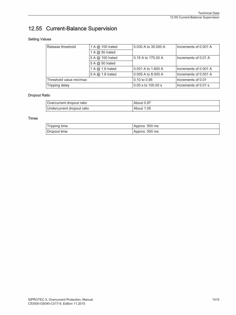
Current-Balance Supervision
Setting Values
Release threshold 1 A @ 100 Irated 0.030 A to 35.000 A Increments of 0.001 A1 A @ 50 Irated5 A @ 100 Irated 0.15 A to 175.00 A Increments of 0.01 A5 A @ 50 Irated1 A @ 1.6 Irated 0.001 A to 1.600 A Increments of 0.001 A5 A @ 1.6 Irated 0.005 A to 8.000 A Increments of 0.001 A
Threshold value min/max 0.10 to 0.95 Increments of 0.01Tripping delay 0.00 s to 100.00 s Increments of 0.01 s
Dropout Ratio
Overcurrent dropout ratio About 0.97Undercurrent dropout ratio About 1.05
Times
Tripping time Approx. 500 msDropout time Approx. 500 ms
12.55
Technical Data12.55 Current-Balance Supervision
SIPROTEC 5, Overcurrent Protection, Manual 1415C53000-G5040-C017-6, Edition 11.2015

Voltage-Balance Supervision
Setting Values
Release threshold value 0,300 V to 170,000 V Increments of 0.001 VThreshold value min/max 0.58 to 0.95 Increments of 0.01Tripping delay 0.00 s to 100.00 s Increments of 0.01 s
Dropout Ratio
Overvoltage dropout ratio Approx. 0.97Undervoltage dropout ratio Approx. 1.05
Times
Tripping time Approx. 500 msDropout time Approx. 500 ms
12.56
Technical Data12.56 Voltage-Balance Supervision
1416 SIPROTEC 5, Overcurrent Protection, ManualC53000-G5040-C017-6, Edition 11.2015

Current-Sum Supervision
Setting Values
Slope of the characteristic curve 0.00 to 0.95 Increments of 0.01Threshold 1 A @ 50 and 100
Irated0.030 A to 10.000 A Increments of 0.001 A
5 A @ 50 and 100Irated
0.15 A to 50.00 A Increments of 0.01 A
1 A @ 1.6 Irated 0.001 A to 1.600 A Increments of 0.001 A5 A @ 1.6 Irated 0.005 A to 8.000 A Increments of 0.001 A
Tripping delay 0.00 s to 100.00 s Increments of 0.01 s
Dropout Ratio
Dropout ratio About 0.97
Times
Tripping time Approx. 500 msDropout time Approx. 500 ms
12.57
Technical Data12.57 Current-Sum Supervision
SIPROTEC 5, Overcurrent Protection, Manual 1417C53000-G5040-C017-6, Edition 11.2015

Voltage-Sum Supervision
Setting Values
Threshold value 0.300 V to 170.000 V Increments of 0.001 VTripping delay 0.00 s to 100.00 s Increments of 0.01 s
Dropout Ratio
Dropout ratio Approx. 0.97
Times
Tripping time Approx. 500 msDropout time Approx. 500 ms
12.58
Technical Data12.58 Voltage-Sum Supervision
1418 SIPROTEC 5, Overcurrent Protection, ManualC53000-G5040-C017-6, Edition 11.2015

Current Phase-Rotation Supervision
Setting Values
Tripping delay 0.00 s to 100.00 s Increments of 0.01 sPhase-rotation direction A B C
A C B
Dropout Ratio
Dropout ratio Approx. 0.97
Times
Tripping time Approx. 500 msDropout time Approx. 500 ms
12.59
Technical Data12.59 Current Phase-Rotation Supervision
SIPROTEC 5, Overcurrent Protection, Manual 1419C53000-G5040-C017-6, Edition 11.2015
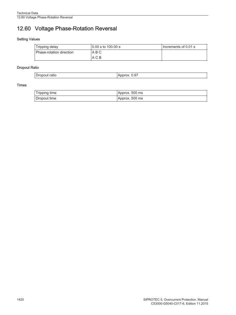
Voltage Phase-Rotation Reversal
Setting Values
Tripping delay 0.00 s to 100.00 s Increments of 0.01 sPhase-rotation direction A B C
A C B
Dropout Ratio
Dropout ratio Approx. 0.97
Times
Tripping time Approx. 500 msDropout time Approx. 500 ms
12.60
Technical Data12.60 Voltage Phase-Rotation Reversal
1420 SIPROTEC 5, Overcurrent Protection, ManualC53000-G5040-C017-6, Edition 11.2015
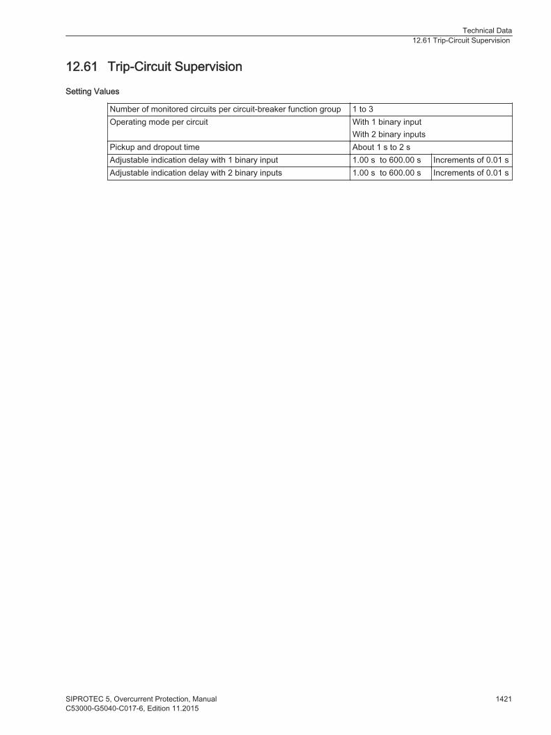
Trip-Circuit Supervision
Setting Values
Number of monitored circuits per circuit-breaker function group 1 to 3Operating mode per circuit With 1 binary input
With 2 binary inputsPickup and dropout time About 1 s to 2 sAdjustable indication delay with 1 binary input 1.00 s to 600.00 s Increments of 0.01 sAdjustable indication delay with 2 binary inputs 1.00 s to 600.00 s Increments of 0.01 s
12.61
Technical Data12.61 Trip-Circuit Supervision
SIPROTEC 5, Overcurrent Protection, Manual 1421C53000-G5040-C017-6, Edition 11.2015
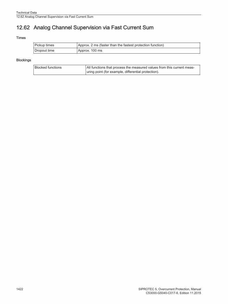
Analog Channel Supervision via Fast Current Sum
Times
Pickup times Approx. 2 ms (faster than the fastest protection function)Dropout time Approx. 100 ms
Blockings
Blocked functions All functions that process the measured values from this current meas-uring point (for example, differential protection).
12.62
Technical Data12.62 Analog Channel Supervision via Fast Current Sum
1422 SIPROTEC 5, Overcurrent Protection, ManualC53000-G5040-C017-6, Edition 11.2015

Measuring-Voltage Failure Detection
Setting Values
3ph.fail. - VA,VB,VC < 0.300 V to 340 000 V Increments of 0.001 V3ph.fail. -phs.curr.release
1 A @ 50 and 100Irated
0.030 A to 35.000 A Increments of 0.001 A
5 A @ 50 and 100Irated
0.15 A to 175.00 A Increments of 0.01 A
1 A @ 1.6 Irated 0.001 A to 1.600 A Increments of 0.001 A5 A @ 1.6 Irated 0.005 A to 8.000 A Increments of 0.001 A
3ph.fail. - phs.curr. jump 1 A @ 50 and 100Irated
0.030 A to 35.000 A Increments of 0.001 A
5 A @ 50 and 100Irated
0.15 A to 175.00 A Increments of 0.01 A
1 A @ 1.6 Irated 0.001 A to 1.600 A Increments of 0.001 A5 A @ 1.6 Irated 0.005 A to 8.000 A Increments of 0.001 A
Asym.fail. - time delay 0.00 s to 30.00 s Increments of 0.01 sSO 3ph.fail. - time delay 0.00 s to 30.00 s Increments of 0.01 s
Dropout Ratio
Overvoltage About 0.95Undervoltage About 1.05
Times
Times Approx. 10 ms + OOT99 at 50 HzApprox. 10 ms + OOT at 60 Hz
Dropout Time Approx. 20 ms + OOT
Times
Use in function group type LineTimes Approx. 10 ms + OOT100 at 50 Hz
Approx. 9 ms + OOT at 60 Hz
Use in other function group typesTimes Approx. 20 ms + OOT101 at 50 Hz
Approx. 18 ms + OOT at 60 Hz
Operating Range
10 Hz to 80 Hz According to specified tolerancesBehavior outside the operating range Active
12.63
99 OOT (Output Operating Time) additional delay of the output medium used, see chapter 12.1.4 Relay Outputs100 OOT (Output Operating Time) additional delay of the output medium used, for example, 5 ms with fast relays, see chapter12.1.4 Relay Outputs101 OOT (Output Operating Time) additional delay of the output medium used, for example, 5 ms with fast relays, see chapter12.1.4 Relay Outputs
Technical Data12.63 Measuring-Voltage Failure Detection
SIPROTEC 5, Overcurrent Protection, Manual 1423C53000-G5040-C017-6, Edition 11.2015
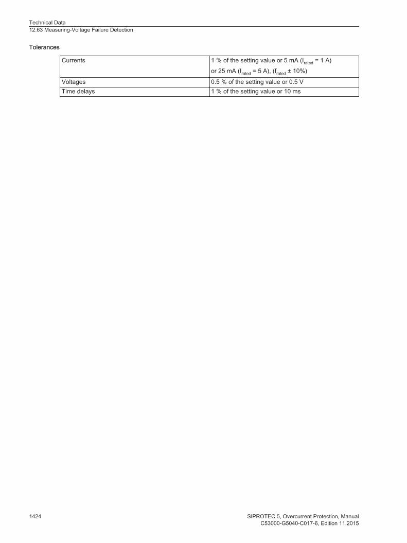
Tolerances
Currents 1 % of the setting value or 5 mA (Irated = 1 A)or 25 mA (Irated = 5 A), (frated ± 10%)
Voltages 0.5 % of the setting value or 0.5 VTime delays 1 % of the setting value or 10 ms
Technical Data12.63 Measuring-Voltage Failure Detection
1424 SIPROTEC 5, Overcurrent Protection, ManualC53000-G5040-C017-6, Edition 11.2015

Voltage-Transformer Circuit Breaker
Setting Values
Response time 0.000 s to 0.030 s Increments of 0.001 s
12.64
Technical Data12.64 Voltage-Transformer Circuit Breaker
SIPROTEC 5, Overcurrent Protection, Manual 1425C53000-G5040-C017-6, Edition 11.2015

Operational Measured Values and Statistical Values
Voltages
VA, VB, VC
Voltage rangeV secondary< 200 V secondary
Secondary rated voltageMeasuring rangeFrequency range
100 V to 125 V(0.8 to 2) · Vrated
49 Hz to 51 Hz at frated = 50 Hz59 Hz to 61 Hz at frated = 60 Hz
Tolerance 0.1 % of the measured value in the above mentionedmeasuring range
Frequency range (expanded) 40 Hz to 60 Hz at frated = 50 Hz50 Hz to 70 Hz at frated = 60 Hz
Tolerance 0.3 % of the measured value in the above mentionedmeasuring range
VAB, VBC, VCA
Voltage rangeV secondary< 200 V
Secondary rated voltageMeasuring rangeFrequency range
100 V to 125 V(0.8 to 2) · Vrated
49 Hz to 51 Hz at frated = 50 Hz59 Hz to 61 Hz at frated = 60 Hz
Tolerance 0.1 % of the measured value in the above mentionedmeasuring range
Frequency range (expanded) 40 Hz to 60 Hz at frated = 50 Hz50 Hz to 70 Hz at frated = 60 Hz
Tolerance 0.3 % of the measured value in the above mentionedmeasuring range
Currents, Instrument Transformers
IA, IB, IC, 3l0Current range
A secondary< 1.6 Irated
Rated currentsMeasuring rangeFrequency range
1 A, 5 A(0.1 to 1.6) · Irated
49 Hz to 51 Hz at frated = 50 Hz59 Hz to 61 Hz at frated = 60 Hz
Tolerance 0.1 % of the measured value in the above mentioned measuring rangeFrequency range(expanded)
40 Hz to 60 Hz at frated = 50 Hz50 Hz to 70 Hz at frated = 60 Hz
Tolerance 0.3 % of the measured value in the above mentioned measuring range
Currents, Protection-Class Current Transformer
IA, IB, IC, 3l0Current range
A secondary< 100 Irated
12.65
Technical Data12.65 Operational Measured Values and Statistical Values
1426 SIPROTEC 5, Overcurrent Protection, ManualC53000-G5040-C017-6, Edition 11.2015
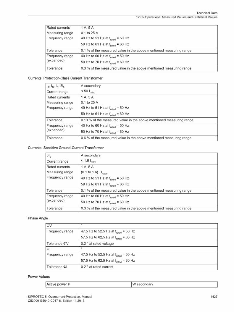
Rated currentsMeasuring rangeFrequency range
1 A, 5 A0.1 to 25 A49 Hz to 51 Hz at frated = 50 Hz59 Hz to 61 Hz at frated = 60 Hz
Tolerance 0.1 % of the measured value in the above mentioned measuring rangeFrequency range(expanded)
40 Hz to 60 Hz at frated = 50 Hz50 Hz to 70 Hz at frated = 60 Hz
Tolerance 0.3 % of the measured value in the above mentioned measuring range
Currents, Protection-Class Current Transformer
IA, IB, IC, 3l0Current range
A secondary< 50 Irated
Rated currentsMeasuring rangeFrequency range
1 A, 5 A0.1 to 25 A49 Hz to 51 Hz at frated = 50 Hz59 Hz to 61 Hz at frated = 60 Hz
Tolerance 0.13 % of the measured value in the above mentioned measuring rangeFrequency range(expanded)
40 Hz to 60 Hz at frated = 50 Hz50 Hz to 70 Hz at frated = 60 Hz
Tolerance 0.6 % of the measured value in the above mentioned measuring range
Currents, Sensitive Ground-Current Transformer
3I0Current range
A secondary< 1.6 Irated
Rated currentsMeasuring rangeFrequency range
1 A, 5 A(0.1 to 1.6) · Irated
49 Hz to 51 Hz at frated = 50 Hz59 Hz to 61 Hz at frated = 60 Hz
Tolerance 0.1 % of the measured value in the above mentioned measuring rangeFrequency range(expanded)
40 Hz to 60 Hz at frated = 50 Hz50 Hz to 70 Hz at frated = 60 Hz
Tolerance 0.3 % of the measured value in the above mentioned measuring range
Phase Angle
ΦV °Frequency range 47.5 Hz to 52.5 Hz at frated = 50 Hz
57.5 Hz to 62.5 Hz at frated = 60 Hz
Tolerance ΦV 0.2 ° at rated voltageΦI °Frequency range 47.5 Hz to 52.5 Hz at frated = 50 Hz
57.5 Hz to 62.5 Hz at frated = 60 Hz
Tolerance ΦI 0.2 ° at rated current
Power Values
Active power P W secondary
Technical Data12.65 Operational Measured Values and Statistical Values
SIPROTEC 5, Overcurrent Protection, Manual 1427C53000-G5040-C017-6, Edition 11.2015

Measuring rangeVoltage rangeCurrent rangeFrequency range
|cosφ| ≥ 0.01(0.8 to 1.2) · Vrated
(0.1 to 2) · Irated
49 Hz to 51 Hz at frated = 50 Hz59 Hz to 61 Hz at frated = 60 Hz
Tolerance 0.3 % of the measured value in the above mentionedmeasuring range
Frequency range (expanded) 40 Hz to 69 Hz at frated = 50 Hz50 Hz to 70 Hz at frated = 60 Hz
Tolerance 0.5 % of the measured value in the above mentionedmeasuring range
Reactive power Q var secondaryMeasuring rangeVoltage rangeCurrent rangeFrequency range
|cosφ| ≥ 0.984(0.8 to 1.2) · Vrated
(0.1 to 2) · Irated
49 Hz to 51 Hz at frated = 50 Hz59 Hz to 61 Hz at frated = 60 Hz
Tolerance 1.0 % of the measured value in the above mentionedmeasuring range
Frequency range (expanded) 40 Hz to 69 Hz at frated = 50 Hz50 Hz to 70 Hz at frated = 60 Hz
Tolerance 1.5 % of the measured value in the above mentionedmeasuring range
Apparent power S VAMeasuring rangeVoltage rangeCurrent rangeFrequency range
(0.01 to 2) · Srated
(0.8 to 1.2) · Vrated
(0.01 to 2) · Irated
49 Hz to 51 Hz at frated = 50 Hz59 Hz to 61 Hz at frated = 60 Hz
Tolerance 0.3 % of the measured value in the above mentionedmeasuring range
Frequency range (expanded) 40 Hz to 69 Hz at frated = 50 Hz50 Hz to 70 Hz at frated = 60 Hz
Tolerance 0.5 % of the measured value in the above mentionedmeasuring range
Frequency
Frequency f HzRange frated - 0.20 Hz < frated + 0.20 Hz
Tolerance ± 5 mHz in the Vrated range
Range frated - 3.00 Hz < frated + 3.00 Hz
Tolerance ± 10 mHz in the Vrated range
Frequency range(expanded)
25 Hz to 80 Hz; operational measured values10 Hz to 80 Hz; functional measured values, system frequency
Tolerance 20 mHz in the range frated ± 10 % for rated values
Technical Data12.65 Operational Measured Values and Statistical Values
1428 SIPROTEC 5, Overcurrent Protection, ManualC53000-G5040-C017-6, Edition 11.2015
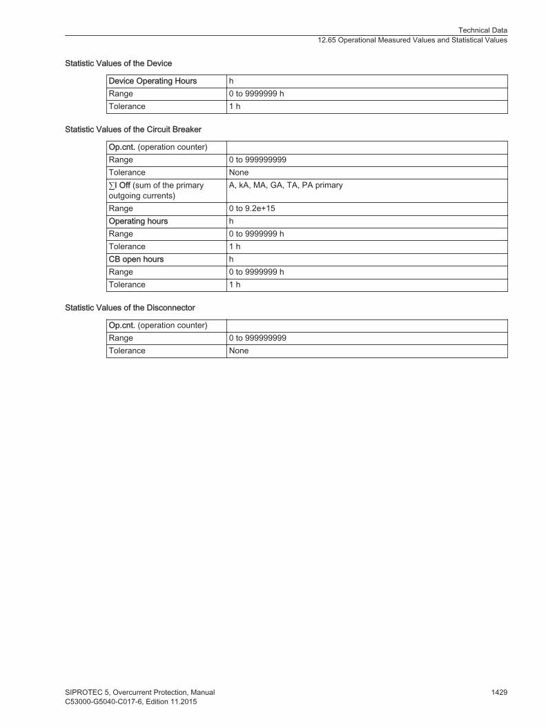
Statistic Values of the Device
Device Operating Hours hRange 0 to 9999999 hTolerance 1 h
Statistic Values of the Circuit Breaker
Op.cnt. (operation counter)Range 0 to 999999999Tolerance None∑I Off (sum of the primaryoutgoing currents)
A, kA, MA, GA, TA, PA primary
Range 0 to 9.2e+15Operating hours hRange 0 to 9999999 hTolerance 1 hCB open hours hRange 0 to 9999999 hTolerance 1 h
Statistic Values of the Disconnector
Op.cnt. (operation counter)Range 0 to 999999999Tolerance None
Technical Data12.65 Operational Measured Values and Statistical Values
SIPROTEC 5, Overcurrent Protection, Manual 1429C53000-G5040-C017-6, Edition 11.2015

Energy Values
Setting Values
Active energy Wp
Reactive energy Wq
kWh, MWh, GWhkvarh, Mvarh, Gvarh
Range ≤ 2% for I > 0.1 Irated,V > 0.1 Vrated
|cosφ| ≥ 0.707Tolerance at rated frequency 1 %
12.66
Technical Data12.66 Energy Values
1430 SIPROTEC 5, Overcurrent Protection, ManualC53000-G5040-C017-6, Edition 11.2015
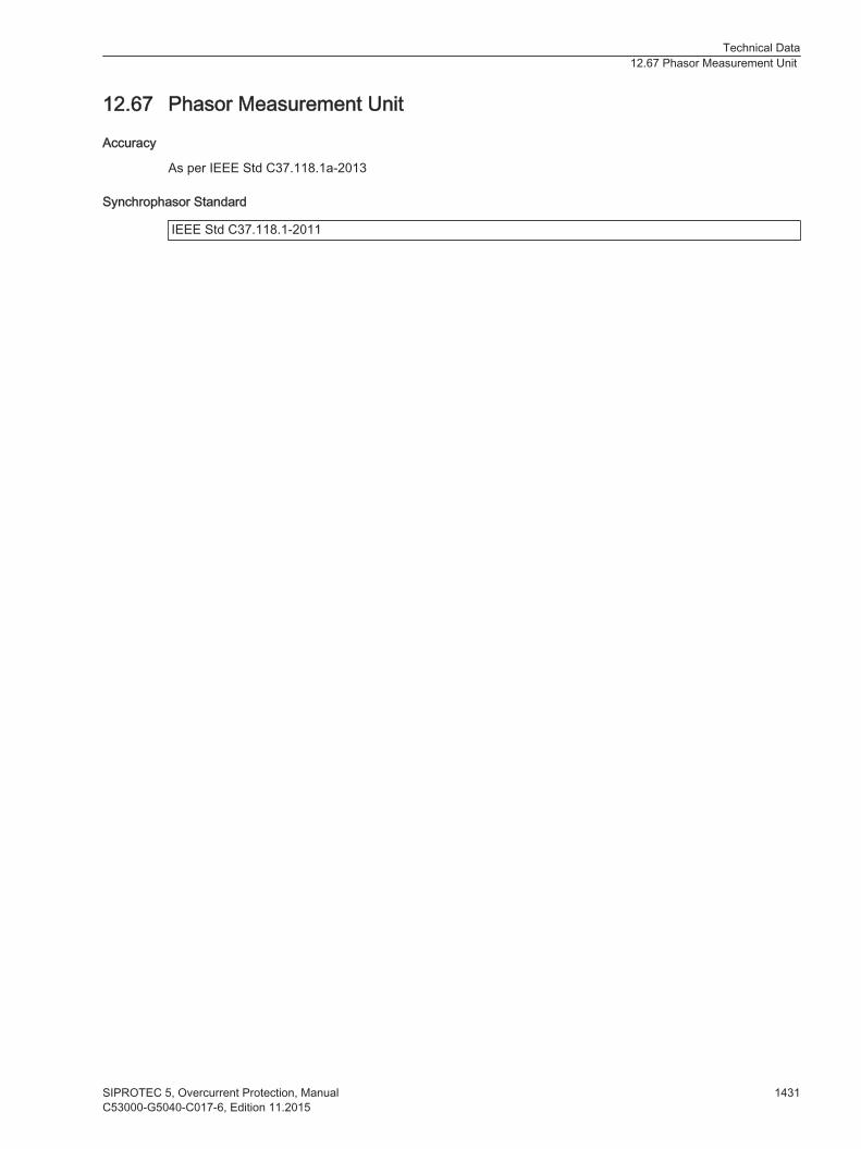
Phasor Measurement Unit
Accuracy
As per IEEE Std C37.118.1a-2013
Synchrophasor Standard
IEEE Std C37.118.1-2011
12.67
Technical Data12.67 Phasor Measurement Unit
SIPROTEC 5, Overcurrent Protection, Manual 1431C53000-G5040-C017-6, Edition 11.2015
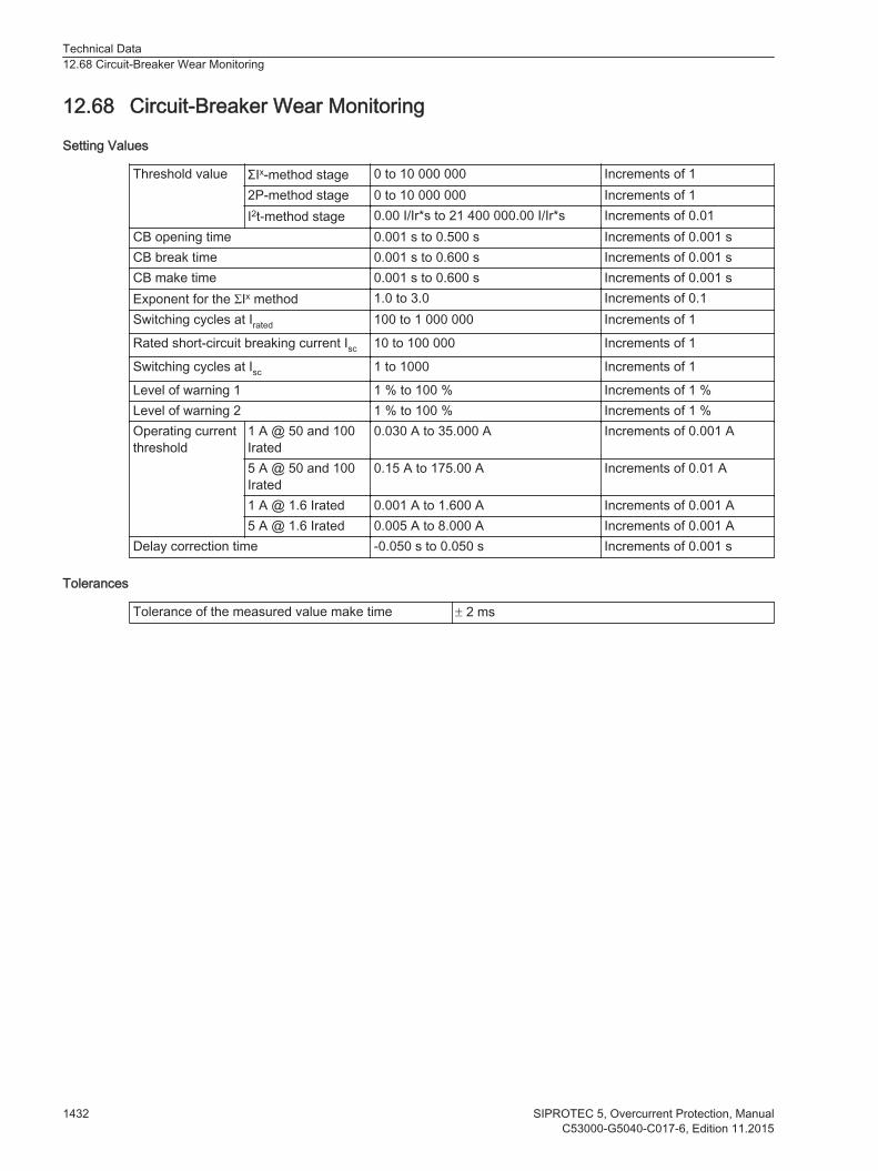
Circuit-Breaker Wear Monitoring
Setting Values
Threshold value ΣIx-method stage 0 to 10 000 000 Increments of 12P-method stage 0 to 10 000 000 Increments of 1I2t-method stage 0.00 I/Ir*s to 21 400 000.00 I/Ir*s Increments of 0.01
CB opening time 0.001 s to 0.500 s Increments of 0.001 sCB break time 0.001 s to 0.600 s Increments of 0.001 sCB make time 0.001 s to 0.600 s Increments of 0.001 sExponent for the ΣIx method 1.0 to 3.0 Increments of 0.1Switching cycles at Irated 100 to 1 000 000 Increments of 1
Rated short-circuit breaking current Isc 10 to 100 000 Increments of 1
Switching cycles at Isc 1 to 1000 Increments of 1
Level of warning 1 1 % to 100 % Increments of 1 %Level of warning 2 1 % to 100 % Increments of 1 %Operating currentthreshold
1 A @ 50 and 100Irated
0.030 A to 35.000 A Increments of 0.001 A
5 A @ 50 and 100Irated
0.15 A to 175.00 A Increments of 0.01 A
1 A @ 1.6 Irated 0.001 A to 1.600 A Increments of 0.001 A5 A @ 1.6 Irated 0.005 A to 8.000 A Increments of 0.001 A
Delay correction time -0.050 s to 0.050 s Increments of 0.001 s
Tolerances
Tolerance of the measured value make time ± 2 ms
12.68
Technical Data12.68 Circuit-Breaker Wear Monitoring
1432 SIPROTEC 5, Overcurrent Protection, ManualC53000-G5040-C017-6, Edition 11.2015
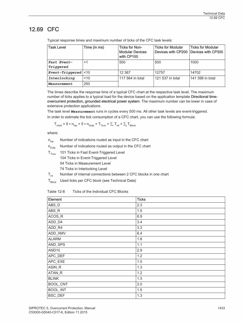
CFC
Typical response times and maximum number of ticks of the CFC task levels:
Task Level Time (in ms) Ticks for Non-Modular Deviceswith CP100
Ticks for ModularDevices with CP200
Ticks for ModularDevices with CP300
Fast Event-Triggered
<1 500 500 1000
Event-Triggered <10 12 367 12757 14702Interlocking <10 117 564 in total 121 537 in total 141 398 in totalMeasurement 250
The times describe the response time of a typical CFC chart at the respective task level. The maximumnumber of ticks applies to a typical load for the device based on the application template Directional time-overcurrent protection, grounded electrical power system. The maximum number can be lower in case ofextensive protection applications.The task level Measurement runs in cycles every 500 ms. All other task levels are event-triggered.In order to estimate the tick consumption of a CFC chart, you can use the following formula:
Tchart = 5 ∙ nInp + 5 ∙ nOutp + TTLev + ∑i Tint + ∑j TBlock
where:
nInp Number of indications routed as input in the CFC chartnOutp Number of indications routed as output in the CFC chartTTLev 101 Ticks in Fast Event-Triggered Level
104 Ticks in Event-Triggered Level54 Ticks in Measurement Level74 Ticks in Interlocking Level
Tint Number of internal connections between 2 CFC blocks in one chartTBlock Used ticks per CFC block (see Technical Data)
Table 12-8 Ticks of the Individual CFC Blocks
Element TicksABS_D 2.3ABS_R 1.5ACOS_R 6.9ADD_D4 3.4ADD_R4 3.3ADD_XMV 6.4ALARM 1.8AND_SPS 1.1AND10 2.9APC_DEF 1.2APC_EXE 1.0ASIN_R 1.3ATAN_R 1.2BLINK 1.3BOOL_CNT 2.0BOOL_INT 1.5BSC_DEF 1.3
12.69
Technical Data12.69 CFC
SIPROTEC 5, Overcurrent Protection, Manual 1433C53000-G5040-C017-6, Edition 11.2015

Element TicksBSC_EXE 1.1BUILD_ACD 2.9BUILD_ACT 2.2BUILD_BSC 1.2BUILD_DPS 1.4BUILD_ENS 1.3BUILD_Q 0.8BUILD_SPS 0.6BUILD_XMV 1.1BUILDC_Q 3.0CHART_STATE 5.9CMP_DPS 1.5CON_ACD 0.7CON_ACT 0.5CONNECT 0.4COS_R 2.5CTD 1.8CTU 1.6CTUD 2.3DINT_REAL 3.0DINT_UINT 3.0DIV_D 2.9DIV_R 1.6DIV_XMV 2.2DPC_DEF 0.4DPC_EXE 0.4DPC_INFO 1.1DPC_OUT 1.3DPS_SPS 1.0DRAGI_R 1.7EQ_D 1.0EQ_R 1.9EXP_R 1.5EXPT_R 2.7F_TRGM 0.3F_TRIG 0.3FF_D 0.9FF_D_MEM 1.4FF_RS 0.7FF_RS_MEM 1.2FF_SR 0.8FF_SR_MEM 1.1GE_D 0.9GE_R 1.1GT_D 0.9GT_R 1.2HOLD_D 1.1
Technical Data12.69 CFC
1434 SIPROTEC 5, Overcurrent Protection, ManualC53000-G5040-C017-6, Edition 11.2015
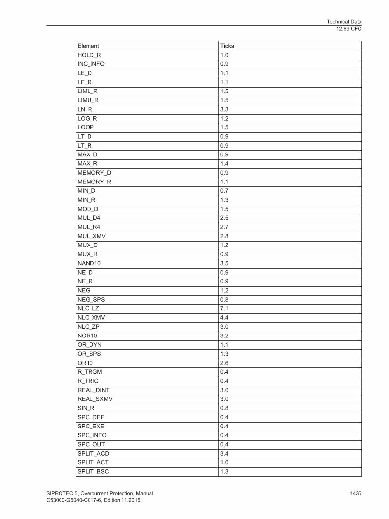
Element TicksHOLD_R 1.0INC_INFO 0.9LE_D 1.1LE_R 1.1LIML_R 1.5LIMU_R 1.5LN_R 3.3LOG_R 1.2LOOP 1.5LT_D 0.9LT_R 0.9MAX_D 0.9MAX_R 1.4MEMORY_D 0.9MEMORY_R 1.1MIN_D 0.7MIN_R 1.3MOD_D 1.5MUL_D4 2.5MUL_R4 2.7MUL_XMV 2.8MUX_D 1.2MUX_R 0.9NAND10 3.5NE_D 0.9NE_R 0.9NEG 1.2NEG_SPS 0.8NLC_LZ 7.1NLC_XMV 4.4NLC_ZP 3.0NOR10 3.2OR_DYN 1.1OR_SPS 1.3OR10 2.6R_TRGM 0.4R_TRIG 0.4REAL_DINT 3.0REAL_SXMV 3.0SIN_R 0.8SPC_DEF 0.4SPC_EXE 0.4SPC_INFO 0.4SPC_OUT 0.4SPLIT_ACD 3.4SPLIT_ACT 1.0SPLIT_BSC 1.3
Technical Data12.69 CFC
SIPROTEC 5, Overcurrent Protection, Manual 1435C53000-G5040-C017-6, Edition 11.2015
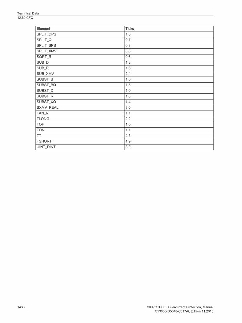
Element TicksSPLIT_DPS 1.0SPLIT_Q 0.7SPLIT_SPS 0.8SPLIT_XMV 0.8SQRT_R 0.6SUB_D 1.3SUB_R 1.6SUB_XMV 2.4SUBST_B 1.0SUBST_BQ 1.5SUBST_D 1.0SUBST_R 1.0SUBST_XQ 1.4SXMV_REAL 3.0TAN_R 1.1TLONG 2.2TOF 1.0TON 1.1TT 2.5TSHORT 1.9UINT_DINT 3.0
Technical Data12.69 CFC
1436 SIPROTEC 5, Overcurrent Protection, ManualC53000-G5040-C017-6, Edition 11.2015