site management template
TRANSCRIPT
Site Management Plan, Site #241063
FORMER JAMAICA GAS LIGHT COMPANY MANUFACTURED GAS PLANT SITE QUEENS, NEW YORK
INTERIM SITE MANAGEMENT PLAN NYSDEC Site Number: 241063
Prepared for: The Brooklyn Union Gas Company d/b/a
National Grid NY One MetroTech Center
Brooklyn, New York 11201
Prepared by: AECOM
125 Broad Street, 16th Floor New York, New York 10004
(212) 377-8400
Revisions to Final Approved Interim Site Management Plan:
Revision No.
Date Submitted Summary of Revision NYSDEC Approval Date
July 2018

Site Management Plan, Site #241063
CERTIFICATION STATEMENT
I, Mike Gardner, certify that I am currently a NYS registered professional engineer as defined in 6 NYCRR Part 375 and that this Interim Site Management Plan was prepared in accordance with all applicable statutes and regulations and in substantial conformance with the DER Technical Guidance for Site Investigation and Remediation (DER-10).
______________________P.E.
______________________DATEJuly 11, 2018
AECOM Interim Site Management Plan i
Site Management Plan, Site #241063
Table of Contents
Executive Summary .......................................................................................................... i
1.0 Introduction ............................................................................................................ 1-1
1.1 General ....................................................................................................................... 1-1
1.2 Revisions .................................................................................................................... 1-1
1.3 Notifications ................................................................................................................ 1-2
1.4 Further Investigation and Possible Remedial Work Plan ........................................... 1-3
1.5 Prior Communication Between National Grid, NYSDEC, and/or the Property Owner 1-4
2.0 Summary of Previous Investigations ................................................................... 2-1
2.1 Site Location and Description ..................................................................................... 2-1
2.2 Physical Setting .......................................................................................................... 2-1 2.2.1 Land Use ...................................................................................................... 2-1 2.2.2 Geology ........................................................................................................ 2-1 2.2.3 Hydrogeology ............................................................................................... 2-2
2.3 Investigation and Remedial History ............................................................................ 2-2 2.3.1 Site History ................................................................................................... 2-2 2.3.2 Site Investigations ........................................................................................ 2-6
3.0 Institutional and Engineering Control Plan .......................................................... 3-1
3.1 General ....................................................................................................................... 3-1
3.2 Institutional Controls ................................................................................................... 3-1 3.2.1 Interim Site Management Plan ..................................................................... 3-1
3.3 Engineering Controls .................................................................................................. 3-2 3.3.1 Cover (or Cap) .............................................................................................. 3-2
4.0 Monitoring Plan ...................................................................................................... 4-1
4.1 General ....................................................................................................................... 4-1
4.2 Site-Wide Inspection ................................................................................................... 4-1
5.0 Operational and Maintenance Plan ....................................................................... 5-1
5.1 General ....................................................................................................................... 5-1
6.0 Reporting Requirements ....................................................................................... 6-1
6.1 Interim Site Management Inspection Reports ............................................................ 6-1

AECOM Interim Site Management Plan ii
Site Management Plan, Site #241063
7.0 References ............................................................................................................. 7-1

AECOM Interim Site Management Plan iii
Site Management Plan, Site #241063
List of Figures Figure 1-1 Site Location Map
Figure 2-1 Parcel Locations
Figure 2-2 Site Layout
Figure 2-3 Historical Structure Locations and Site Boundary
Figure 2-4 Site Characterization and Remedial Investigation Sample Locations
Figure 2-5 Surface Soil Analytical Results
Figure 2-6 Subsurface Soil Analytical Results
Figure 3-1 Decision Tree
Figure 3-2 Limits of Interim Site Management Plan
List of Tables
Table 1-1 Notifications (Embedded in text)
Table 3-1 Matrix of Responsibility
List of Appendices
Appendix A Monitoring Well Boring and Construction Logs
Appendix B Site Management Form
Appendix C List of Site Contacts
Appendix D Excavation Work Plan
Appendix E Sample Health and Safety Plan
Appendix F Community Air Monitoring Plan

AECOM Interim Site Management Plan iv
Site Management Plan, Site #241063
List of Acronyms
AWQSGV Ambient Water Quality Standards and Guidelines Values
BUG Brooklyn Union Gas
CAMP Community Air Monitoring Plan
CFR Code of Federal Regulations
CUNY City University of New York
DASNY Dormitory Authority of the State of New York
DER-10 NYSDEC DER-10 Technical Guidance for Site Investigation and Remediation
ECL Environmental Conservation Law
EWP Excavation Work Plan
HASP Health and Safety Plan
HAZWOPER Hazardous Waste Operations and Emergency Responses
IC Institutional Controls
ISMP Interim Site Management Plan
LIRR Long Island Rail Road
MGP Manufactured Gas Plant
NAPL Non Aqueous Phase Liquid
NYCRR New York Codes Rules and Regulations
NYS New York State
NYSDEC New York State Department of Environmental Conservation
NYSDOH New York State Department of Health
OASIS Open Accessible Space Information System Cooperative
OSHA Occupational Safety and Health Administration
PAHs Polycyclic Aromatic Hydrocarbons
PID Photo-ionization Detector
PPE Personnel Protective Equipment
QHHEA Qualitative Human Health Exposure Assessment
RI Remedial Investigation
SC Site Characterization
SCG Standards, Criteria, and Guidance
SCO Soil Cleanup Objectives
Site Former Jamaica Gas Light Company Manufactured Gas Plant
USGS United States Geological Survey

AECOM Interim Site Management Plan v
Site Management Plan, Site #241063
Units and Measurements
bgs below ground surface
kg kilograms
mg milligram

AECOM Interim Site Management Plan i
Site Management Plan, Site #241063
Executive Summary
The following provides a brief summary of the interim controls implemented for the Site area managed under the ISMP, as well as the inspections, monitoring, maintenance and reporting activities required by this Interim Site Management Plan (ISMP):
Site Identification: New York State Department of Environmental Conservation (NYSDEC) Site No. 241063
Former Jamaica Gas Light Company Manufactured Gas Plant (MGP) Site, Jamaica, Queens County, NY
158-18 Beaver Road, Queens, NY 11433
Interim Institutional Controls: 1. The Site area managed under this ISMP may be used for commercial use.
2. Notification must be given to National Grid and NYSDEC prior to any surface-intrusive work and any work must be conducted in accordance with this ISMP and in consultation and approval from National Grid and with review from NYSDEC
3. No farms or vegetable gardens. Interim Engineering Controls: Cover system comprised of concrete-, asphalt-, and grass-
covered ground surfaces. The site is secured with an existing fence.
Inspections Frequency
1. Site-wide Inspection 2. Emergency Inspection
1. Annually 2. As needed
Monitoring Frequency Not required until the remedy is completed, except when intrusive activities dictate environmental oversight.
NA
Reporting Frequency Interim Site-Wide Inspection Summary
Annually
The property owner is required to comply with this ISMP including all notifications to National Grid. National Grid is only responsible for the costs associated with MGP-related impacts. Further descriptions of the above requirements are provided in detail in the latter sections of this ISMP. Until the final SMP, this ISMP will be considered the Institutional Controls (IC) and will be incorporated into Site operations to control exposure to subsurface impacts to ensure protection of public health and the environment.

AECOM Interim Site Management Plan 1-1
Site Management Plan, Site #241063
1.0 Introduction
1.1 General
This Interim Site Management Plan (ISMP) has been prepared on behalf of National Grid to alert site workers and construction, utility, and maintenance crews, and their contractors (“Construction Workers”) of the environmental conditions at the Former Jamaica Gas Light Company Manufactured Gas Plant (MGP) Site located in Queens, New York (hereinafter referred to as the “Site”). These conditions may impact surface-intrusive activities and present a hazard to the public and environment. See Figure 1-1 for the location of the Site. The Site is currently in the New York State (NYS) Superfund Program (Site No. 241063) which is administered by the New York State Department of Environmental Conservation (NYSDEC). Based on available historical records, the former MGP was operated by the Jamaica Gas Light Company from at least 1873 to 1895. The Brooklyn Union Gas (BUG) Company purchased the Jamaica Gas Light Company between 1895 and 1897 and operated the MGP until 1901 when it is believed to have been converted to a gas storage and distribution facility. This facility eventually ceased operation in approximately 1938. The Site is currently owned by the Dormitory Authority of the State of New York (DASNY) and used for commercial purposes. National Grid entered into an Order on Consent (Index #A2-0552-0606) with the NYSDEC to remediate the Site.
After completion of the Site Characterization (SC) and Remedial Investigation (RI), surface-intrusive activities within the Site were identified as a potential exposure pathway which may result in contact with MGP-related impacts at the Site. Thus, Institutional Controls (ICs) have been incorporated at the Site as a temporary control to reduce exposure to MGP-related impacts and ensure protection of public health and the environment prior to implementation of a remedial action.
This ISMP will be provided to the current Site property owner by National Grid. This plan is also on-file with the NYSDEC. Any revisions to this ISMP shall be provided to the current Site property owner and the file maintained by the NYSDEC.
It is important to note that failure to comply with this ISMP is a violation of Environmental Conservation Law (ECL) 6 New York Codes Rules and Regulations (NYCRR) Part 375 and the Order on Consent (Index #A2-0552-0606; Site No. 241063) for the Site, and thereby subject to applicable penalties. This ISMP was prepared to manage the MGP-related impacts at the Site in accordance with NYS Environmental Conservation Law (ECL) Article 71, Title 36, or until this ISMP is superseded by another SMP approved by the NYSDEC. All reports associated with the Site can be viewed by contacting the NYSDEC or its successor agency managing environmental issues in NYS.
This ISMP was prepared by AECOM, on behalf of National Grid, in accordance with the requirements of the NYSDEC’s Division of Environmental Remediation (DER)-10 (“Technical Guidance for Site Investigation and Remediation”), dated June 2010 (NYSDECa, 2010), and the guidelines provided by the NYSDEC. This ISMP addresses the means for implementing the ICs that will be required for the Site.
1.2 Revisions
Revisions to this ISMP will be proposed in writing to the NYSDEC’s project manager as an addendum. Revisions will be necessary upon, but not limited to, the following occurring: a change in media
AECOM Interim Site Management Plan 1-2
Site Management Plan, Site #241063
monitoring requirements, upgrades to or shutdown of remedial system, post-remedial removal of contaminated sediment or soil, or other significant change to the Site conditions. The NYSDEC will provide a notice of any approved changes to the ISMP and append these notices to the ISMP that is retained in its files.
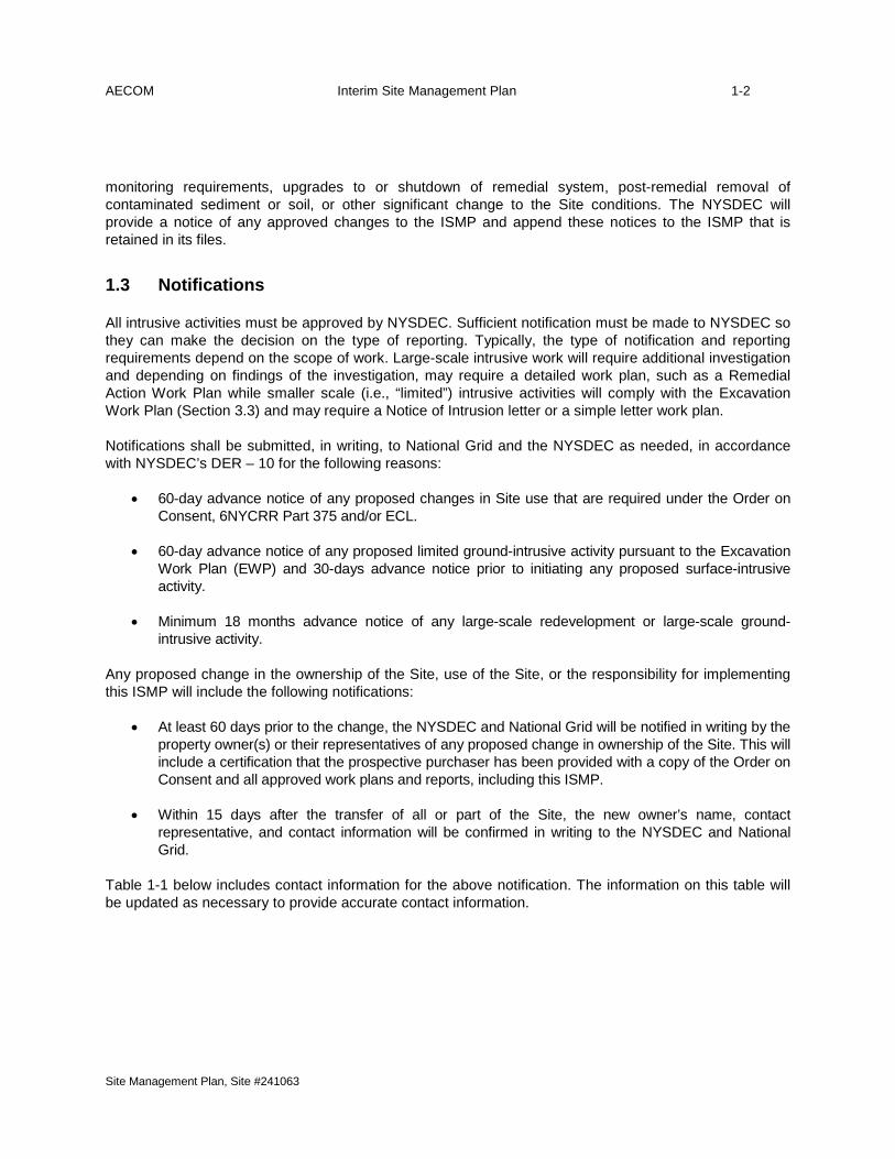
1.3 Notifications
All intrusive activities must be approved by NYSDEC. Sufficient notification must be made to NYSDEC so they can make the decision on the type of reporting. Typically, the type of notification and reporting requirements depend on the scope of work. Large-scale intrusive work will require additional investigation and depending on findings of the investigation, may require a detailed work plan, such as a Remedial Action Work Plan while smaller scale (i.e., “limited”) intrusive activities will comply with the Excavation Work Plan (Section 3.3) and may require a Notice of Intrusion letter or a simple letter work plan.
Notifications shall be submitted, in writing, to National Grid and the NYSDEC as needed, in accordance with NYSDEC’s DER – 10 for the following reasons:
• 60-day advance notice of any proposed changes in Site use that are required under the Order on Consent, 6NYCRR Part 375 and/or ECL.
• 60-day advance notice of any proposed limited ground-intrusive activity pursuant to the Excavation Work Plan (EWP) and 30-days advance notice prior to initiating any proposed surface-intrusive activity.
• Minimum 18 months advance notice of any large-scale redevelopment or large-scale ground-intrusive activity.
Any proposed change in the ownership of the Site, use of the Site, or the responsibility for implementing this ISMP will include the following notifications:
• At least 60 days prior to the change, the NYSDEC and National Grid will be notified in writing by the property owner(s) or their representatives of any proposed change in ownership of the Site. This will include a certification that the prospective purchaser has been provided with a copy of the Order on Consent and all approved work plans and reports, including this ISMP.
• Within 15 days after the transfer of all or part of the Site, the new owner’s name, contact representative, and contact information will be confirmed in writing to the NYSDEC and National Grid.
Table 1-1 below includes contact information for the above notification. The information on this table will be updated as necessary to provide accurate contact information.
AECOM Interim Site Management Plan 1-3
Site Management Plan, Site #241063
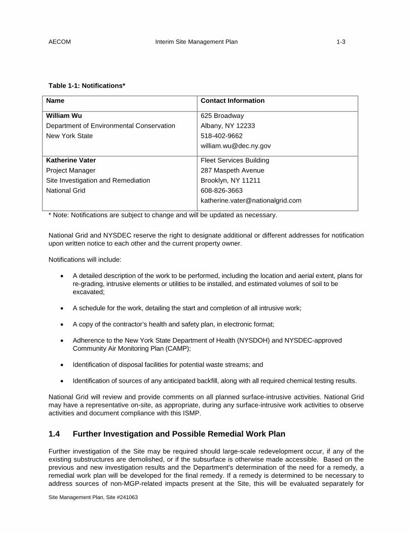
Table 1-1: Notifications*
Name Contact Information
William Wu Department of Environmental Conservation New York State
625 Broadway Albany, NY 12233 518-402-9662 [email protected]
Katherine Vater Project Manager Site Investigation and Remediation National Grid
Fleet Services Building 287 Maspeth Avenue Brooklyn, NY 11211 608-826-3663 [email protected]
* Note: Notifications are subject to change and will be updated as necessary. National Grid and NYSDEC reserve the right to designate additional or different addresses for notification upon written notice to each other and the current property owner. Notifications will include:
• A detailed description of the work to be performed, including the location and aerial extent, plans for re-grading, intrusive elements or utilities to be installed, and estimated volumes of soil to be excavated;
• A schedule for the work, detailing the start and completion of all intrusive work;
• A copy of the contractor’s health and safety plan, in electronic format;
• Adherence to the New York State Department of Health (NYSDOH) and NYSDEC-approved Community Air Monitoring Plan (CAMP);
• Identification of disposal facilities for potential waste streams; and
• Identification of sources of any anticipated backfill, along with all required chemical testing results.
National Grid will review and provide comments on all planned surface-intrusive activities. National Grid may have a representative on-site, as appropriate, during any surface-intrusive work activities to observe activities and document compliance with this ISMP.
1.4 Further Investigation and Possible Remedial Work Plan
Further investigation of the Site may be required should large-scale redevelopment occur, if any of the existing substructures are demolished, or if the subsurface is otherwise made accessible. Based on the previous and new investigation results and the Department's determination of the need for a remedy, a remedial work plan will be developed for the final remedy. If a remedy is determined to be necessary to address sources of non-MGP-related impacts present at the Site, this will be evaluated separately for
AECOM Interim Site Management Plan 1-4
Site Management Plan, Site #241063
further action. A Citizen Participation Plan (CPP) will continue through this process. Any necessary remediation will be completed prior to, or in association with, redevelopment.
1.5 Prior Communication Between National Grid, NYSDEC, and/or the Property Owner
Communications between National Grid, NYSDEC, and/or the property are described below:
• Access Agreements from 2011 and 2013
• Correspondences between National Grid, NYSDEC, and property owner regarding work to be performed at Site

AECOM Interim Site Management Plan 2-1
Site Management Plan, Site #241063
2.0 Summary of Previous Investigations
2.1 Site Location and Description
The Site is located in Jamaica, Queens County, New York and is identified as Block 10099 and Lot 1 on the New York City Tax Map (see Figure 2-1). The Site is less than 1-acre in area and is bounded by the Long Island Rail Road (LIRR) Right of Way to the north, the Prospect Cemetery and a commercial property owned by the DASNY to the south, vacant land and the York College of the City University of New York (CUNY) campus to the east, and 158th Street and commercial businesses to the west (see Figure 2-2).
2.2 Physical Setting
2.2.1 Land Use The Site appears to have been a relatively flat property that originally sloped slightly from northeast to southwest. The Site is currently paved with no significant slope. The property encompassing the Site is currently fenced and contains numerous roll-off containers and trash compactors. The City of New York Department of Finance has listed the property as Building Class V5, which indicates vacant land. The City of New York Department of City Planning has listed the zone classification for this area as R6, which indicates residential property with moderate density. The Site is currently utilized for commercial purposes.
The current property owner for the Site is listed as DASNY based on New York City Department of Finance website information obtained from the New York City Open Accessible Space Information System Cooperative (OASIS) on-line database.
2.2.2 Geology The Site geology consists of two unconsolidated units varying in thickness and distribution: fill and sand. No confining units or bedrock surface was encountered during the SC and RI. The SC and RI borings were advanced to a maximum depth of 45 feet below ground surface (bgs), which was not deep enough to determine the presence and depth of the Gardiner’s Clay which may occur sporadically or be absent in the Site vicinity. If present in the Site vicinity, Gardiner’s Clay is estimated to occur at depths ranging between 75 and 90 feet bgs (Buxton and Shernoff, 1999). The top of bedrock is estimated to be at depths greater than 500 feet bgs in the Site vicinity (Misut and Monti, 1999).
The fill upper unit, consisting of poorly-graded sand and gravel with varying amounts of debris, is observed to be present in all areas of the Site in thicknesses ranging from 3 to 19 feet.
A sand native unit was comprised of subunits of well-graded sand and poorly-graded sand. The well-graded sand is composed of light to dark brown, medium to fine sand, and less than 15% coarse subangular gravel, with a few thin layers of fine sand or rounded gravel. Well-graded sand was typically encountered directly below the fill unit and generally ranged from 18.5 to 35 feet in thickness. The poorly-graded sand is composed of predominately fine sand and ranges from 2.5 to 5 feet in thickness within the well-graded sand unit. The maximum boring depth during the investigations was 45 feet bgs, and the

AECOM Interim Site Management Plan 2-2
Site Management Plan, Site #241063
bottom of the well-graded sand was not encountered at that depth. Silty sand and sandy silt lenses were observed intermittently along the southern portion of the Site within the well-graded sand unit as discontinuous lenses or pockets. A thin lens of clay and silty clay was encountered within the sand unit in the southwestern portion of the Site.
2.2.3 Hydrogeology Groundwater at the Site is in the overburden at depths ranging from approximately 13 to 27 feet bgs. Groundwater generally flows from north/northeast to the south/southwest.
Groundwater monitoring well locations are indicated in Figure 2-4 and monitoring well construction logs are provided in Appendix A.
2.3 Investigation and Remedial History
The Site was operated by the Jamaica Gas Light Company and later BUG from prior to 1873 to approximately 1938. A review of historical documents indicates that the Site was operated by the Jamaica Gas Light Company as a manufactured gas plant for at least 25 years in the late 1800s before being converted to a gas storage and distribution facility around 1900 when two smaller holders (Holders No. 1 and 2) and structures associated with the MGP were demolished. The remaining large gas holder (Holder No. 3) and associated gas storage and distribution structures were demolished in 1938. Figure 2-3 shows the locations of historic site structures. The property was subsequently used as office space by BUG until the late 1960s and then left vacant. No buildings have been built on the Site since then, and the Site is actively used by Royal Waste Services, Inc. for equipment storage. Other than the presence of roll-off containers and trash compactors currently stored on the Site, no other uses of the property have been identified since the 1960s. The Site is currently owned by the DASNY.
Immediately adjacent to and north of the Site is a major transportation hub, the Jamaica Center LIRR station and the Metropolitan Transportation Authority’s New York City Subway E, J, and Z, lines. To the south of the Site is Prospect Cemetery and to the west of the Site, across 158th Street are a roll-off storage yard and an automotive parts manufacturer as well as other industrial buildings. The Prospect Cemetery and the LIRR Right of Way have been located to the south and the north of the Site, respectively, since 1886. Vacant lots and commercial establishment have been consistently located to the east and west of the Site since the late 1800s.
The following sections provide site and remedial history and a brief summary of the available project records to document key investigative and remedial milestones for the Site. Full titles for each of the reports referenced below are provided in Section 4.0 - References.
2.3.1 Site History The Brooklyn Union Gas Company (BUG) was incorporated in September 1895, by interests affiliated with The Standard Oil Company (Standard Oil), to consolidate seven gas companies for the purpose of growing and controlling the market for Standard Oil’s products, which were used in the carburation of gas. This market had been created by The Standard Oil Company circa 1879, when Standard Oil backed The Fulton Municipal Gas Company, which ran the first carbureted water gas plant in Brooklyn; supplied the plant with its naphtha; and then, between the early 1880s and mid-1890s, used the plant in gas wars waged on other Brooklyn gas companies with the goal of controlling them and ultimately consolidating them.
AECOM Interim Site Management Plan 2-3
Site Management Plan, Site #241063
There was an interim board of directors for the first year of BUG’s incorporation1,2 E. R. Chapman, “a recognized representative of the [sic] Standard Oil Company,” was elected Treasurer.3 At the November 1896 annual meeting, the elected directors included H. H. Rogers and William Rockefeller. H. H. Rogers was elected vice-president, later in the month, at a meeting of the board of directors.4,5 Meetings of the BUG board of directors were held in Manhattan, at or near the offices of Standard Oil, rather than at the offices of BUG, in Brooklyn.6 Board meetings continued to be held in Manhattan at least into 1914.7
Increasing its customer base and therefore the use of Standard Oil products, on July 30, 1897, BUG acquired The Jamaica Gas Light Company by stock purchase. The Jamaica Gas Light Company had been incorporated in 1856, and unlike BUG, its corporate rights allowed it to operate in Queens.8 Based on Sanborn maps for 1886 and 1891, The Jamaica Gas Light Company originally produced gas by coal carbonization. Changes appear to have occurred rapidly around the time of the BUG acquisition. An 1897 Sanborn map indicates that the works had been converted to manufacturing carbureted water gas. Circa 1898 a new, larger holder had been erected.9 And, according to a 1901 Sanborn map, The Jamaica Gas Light Company works and holders had been abandoned. The circa 1898 holder would have stored gas produced at other BUG works.
In 1909, following settlement of a rate case with the New York Public Service Commission, Standard Oil gave BUG a rebate of $702,157.02.10 The rebate was based on credits for Standard Oil delivering a lower grade of gas oil than required by contract in 1904 and for increasing the price of gas oil on two other occasions. At about this time, Standard Oil operatives maintained an ownership interest of approximately 10% in BUG.11 Through at least 1919, Standard Oil remained the sole supplier of petroleum to BUG.12 William A. Rockefeller, Jr. served as the Executive Committee Chairman of BUG until his death in June 1922.13,14 A “Resolution, commemorative of his decease,” adopted by the BUG board of directors states William Rockefeller was “one of the organizers of the Company and since its inception a member of the Board of Directors and Chairman of the Executive Committee. In his indefatigable service on the Board for a period of nearly twenty-seven years he was a potent influence on the upbuilding of the Company.”15
By the mid-1920s, The American Light and Traction Company (American), a holding company organized for the purchase and reorganization of utilities and street railroads, had acquired an approximately 30% ownership interest in BUG.16 The United Light and Power Company (United), another holding company,
1 Murphy, pp. 22-27, 47. 2 Minutes of the Board of Directors of the Brooklyn Union Gas Company. 1895 - 1896. 3 Progressive Age, Volume XIII, p. 332, 1895. 4 Minutes of the Board of Directors of the Brooklyn Union Gas Company. 1896. 5 Murphy, pp. 21-27. 6 Minutes of the Board of Directors of the Brooklyn Union Gas Company. 1895 - 1896. 7 Murphy, pp. 39-40. 8 “Brooklyn Union’s Proposed Merger Approved Today.” The Brooklyn Daily Eagle. 10 November 1927, p. 23. 9New York City Department of Buildings, Gas Holder Construction Information, 1916, 1920, and 1921. 10 “Standard Oil Gave B’klyn Union Gas $700,000 Rebate.” The Evening World 29 December 1915, p. 2. 11 Murphy, p. 39. 12 Ibid, p. 44. 13 Ibid, p. 47. 14 Illuminated Resolution of the Board of Directors. Rockefeller Archive Center. William Rockefeller Collection, Record Group RG50, Series 1, Box 1, Folder 6. 15 Ibid. 16 Koppers United Co. v. Securities Exchange Commission. 138 F.2d 577 (D.C. Cir. 1943) | Casetext.
AECOM Interim Site Management Plan 2-4
Site Management Plan, Site #241063
had an ownership interest in American.17 In 1924, Koppers also made an investment in American, and Henry B. Rust, president of Koppers, was elected to the American board of director.18 By this time, “the Koppers interests had adopted the policy of acquiring coke producing properties at strategic points along the Atlantic Seaboard for the purpose of establishing a monopoly of that business in that area” and had formulated a plan for expanding its coke business.19,20
In spring 1925 BUG acquired property in Greenpoint for the construction of a combined carbureted water gas and by-product coke-oven plant.21 On November 30, 1925, BUG stockholders “authorized, subject to approval by the Public Service Commission, the issue of $11,800,000 convertible debenture bonds” to be dated January 1, 1926, and “voted to increase the capital stock of the company from 600,000 to 1,000,000 shares in order to provide for the conversion of the debenture bonds into stock.”22 Construction of the combined plant, for which plans had been “kept in the drawer for many years,” began in the winter of 1925-1926.23
In the fall of 1927, now chairman of the executive committee of American, Henry B. Rust began discussions with BUG to purchase the by-product coke plant at Greenpoint.24 The presidents of United and American, who were philosophically opposed to Koppers’ business model, intervened and convinced BUG not to sell the coke-oven plant to Koppers.25 To resolve the impasse, it was agreed that Koppers would obtain from American all of its holdings in BUG, allowing Koppers to negotiate with BUG for the sale of the coke-oven plant, which began operation in November 1928. 26,27,28
By December 31, 1927, Koppers maintained an approximate 4% ownership interest in BUG. Koppers direct acquisition of BUG stock coincides with changes in BUG’s corporate structure “…believed to be a forerunner of financing plans...”29 On October 10, 1927, it was announced that plans had “been completed for the absorption of the company’s wholly-owned subsidiaries.”30 On November 10, 1927, at a special meeting, stockholders “…approved the legalization of the company’s operations in Queens County.”31 The “proposed change in the [sic] Brooklyn Union’s certificate” was to “come before the Public Service Commission for approval” on November 21, 1927.32 And, on December 31, 1927, subsidiary gas companies that had been acquired in 1895 and 1897, including The Jamaica Gas Light Company, were merged with BUG.
17 Helfman v. American Light Traction Co., 121 N.J. Eq. 1. (N.J. 1936) | Casetext. 18 Ibid. 19 The United Light and Power Company v. Commissioner of Internal Revenue. 38 B.T.A 477 (1938) | Google Scholar. 20 Helfman v. American Light Traction Co., 121 N.J. Eq. 1. (N.J. 1936) | Casetext.. 21 Murphy, pp. 51-52. 22 “Brooklyn Union Gas Stockholders Vote Bond Issue.” The Brooklyn Daily Eagle. 30 November 1925, p. 19. 23 Ibid. pp. 51-52. 24 The United Light and Power Company v. Commissioner of Internal Revenue. 38 B.T.A 477 (1938) | Google Scholar. 25 Ibid. 26 Ibid. 27 Murphy, p. 53. 28 Koppers United Co. v. Securities Exchange Commission. 138 F.2d 577 (D.C. Cir. 1943) | Casetext. 29 “Brooklyn Union Ready to Absorb Subsidiaries.” The Brooklyn Daily Eagle. 10 October 1927, p. 2. 30 Ibid. 31 “Brooklyn Union’s Proposed Merger Approved Today.” The Brooklyn Daily Eagle. 10 November 1927, p. 23. 32 Ibid.

AECOM Interim Site Management Plan 2-5
Site Management Plan, Site #241063
Koppers, with the acquisition of American’s holdings, in July 1928, brought its total ownership interest in BUG to approximately 34%.33,34,35 BUG now agreed to sell the coke-oven plant to Koppers, who greatly expanded the plant and operated it until 1930, when the New York Public Service Commission “blocked the sale.”36 Subsequently, BUG took over the plant and the Koppers staff which operated it.37 With the completion of the combined carbureted water gas and coke-oven plant, most of BUG’s gas plants had their production gradually decreased until they were taken out of service. The holder constructed circa 1898 at the site of The Jamaica Gas Company’s former works was purged and no longer in service by August 19, 1935.38 By September 23, 1938, the holder had been demolished and the tank filled.39 According to Sanborn maps, through at least 1942 the property continued to be used for a meter/engine room/boiler building and for storage, and by 1951 the property was used as offices for The Brooklyn Union Gas Company, Queens Service Station.
During the period of Koppers ownership, BUG bought all its coal from Koppers and sold all its surplus coke to Koppers.40 The directors of BUG “exerted only the most casual supervision over the prices involved in the inter-company sales.”41 They gave “no serious consideration to the possibility of finding coke markets other than Koppers, although other concerns made unsolicited and unsuccessful attempts to buy Brooklyn's coke.”42 Based on a 1943 New York Supreme Court decision, going forward from at least September 26, 1934, Koppers received unlawful profits from BUG, in violation of the New York State Public Service Law.43 Consequently, the New York State Supreme Court, ordered Koppers to pay $346,358.35, with interest, approximately $479,000, to BUG, minus income tax and lawyers’ and accountants’ fees for both the BUG directors and the plaintiffs.44,45
Having petitioned the Securities and Exchange Commission to declare that BUG was not its subsidiary, the application having been denied, and all appeals having been lost, on March 29, 1944, Koppers sold its ownership interest in BUG.46 The next day, a Koppers vice-president, who had served on the BUG board since 1939, resigned.47
The Standard Oil Company, The American Light and Traction Company, The United Light and Power Company, and Koppers have been succeeded by other corporations, are doing business under other names, and/or are defunct. The successor to The Standard Oil Company is ExxonMobil. Successors to The American Light and Traction Company include American Natural Resources Company, a wholly-
33 “B’klyn Gas Deal Unverified.” The Brooklyn Daily Eagle. 20 September 1928, p. 23. 34 Koppers United Co. v. Securities Exchange Commission. 138 F.2d 577 (D.C. Cir. 1943) | Casetext. 35 In 1929, Koppers’ approximate 34% ownership was reduced to 23.87% when debenture bonds that had been issued by The Brooklyn Union Gas Company in 1926 were converted to stocks. (“Brooklyn Union Gas Lists More Stock.” The Brooklyn Daily Eagle 16 December 1928, p. 39.) 36 Murphy, p. 53. 37 Koppers United Co. v. Securities Exchange Commission. 138 F.2d 577 (D.C. Cir. 1943) | Casetext. 38 The Brooklyn Union Gas Company, Drawing No. 6-B-50, 1913, last revised November 12, 1935. 39 The Brooklyn Union Gas Company, Photograph Nos. 35666 and 35667. 40 Koppers United Co. v. Securities Exchange Commission. 138 F.2d 577 (D.C. Cir. 1943) | Casetext. 41 Ibid. 42 Ibid. 43 Weis v. Coe. 180 Misc. 321 (N.Y. Misc. 1943) | Casetext. 44 Ibid. 45 Murphy, p. 64. 46 Murphy, p. 63. 47 Murphy, pp. 63-64.

AECOM Interim Site Management Plan 2-6
Site Management Plan, Site #241063
owned subsidiary of TransCanada Corporation, and DTE Energy. The successor to Koppers is Beazer. The United Light and Power Company was liquidated and dissolved in 1950, with its liabilities ultimately passing to the Iowa-Illinois Gas & Electric Company, now MidAmerican Energy Company.
2.3.2 Site Investigations To determine whether the soil and groundwater were impacted by the MGP above levels of concern, data from the SC and RI were compared to the following standards, criteria, and guidance (SCGs):
• Groundwater SCGs are based on the NYSDEC Ambient Water Quality Standards and Guidance Values [(AWQSGV), NYSDEC, 1998]; and
• Soil SCGs are based on the NYSDEC DER, 6 NYCRR Part 375 Restricted Commercial Use Soil Cleanup Objectives (SCOs), as well as NYSDEC’s alternative polycyclic aromatic hydrocarbons (PAH) criterion for non-residential sites, total PAH of 500 milligram (mg)/kilogram (Kg), specified in NYSDEC Policy CP-51 Soil Cleanup Guidance (NYSDEC, 2010b).
Some MGP-related impacts are present beneath the Site and are generally to the center and southern area of the Site within the vicinity of the two smaller holders and the former Purifier and Meter room (see Figure 2-3). These impacts included moderate naphthalene-like odors, staining, suspected purifier-like material, and light to moderate non aqueous phase liquid (NAPL)-like coating of soil particles. The MGP-related impacts ranged from 3 to 33 feet bgs and have been vertically delineated. The MGP-related impacts generally reduced in extent laterally and below the foundation of the historical MGP structures.
Groundwater beneath the Site did not contain MGP-related constituents at concentrations exceeding the AWQSGVs. The inorganic compounds, detected at concentrations exceeding the AWQSGVs, occur naturally in the aquifer and are not related to the historic MGP operations.
The subsurface soil impacts are of limited extent and do not extend to neighboring property boundaries to the north, east, and west of the Site. Analytical exceedances were detected within subsurface soils along the southern property boundary. Surface soil analytical data indicated constituent concentrations below SCOs for Commercial Land Use and are only slightly above SCOs for Restricted Residential Land Use.
The results of the SC and RI indicated that MGP-related impacts are limited based on visual observation and generally confirmed by limited low-level soil and groundwater analytical detections. Total PAH concentrations only exceeded the CP-51 alternative criterion of 500 mg/Kg in three subsurface soil samples. The weathered aspect of the impacts are consistent with the Site history, particularly that gas manufacturing ended in the early 1900s, and that following that, the Site was only used for gas storage and distribution and was eventually paved.
Based on the character and distribution of the MGP-related impacts, it appears that a limited quantity of material was released to the subsurface in the vicinity of the former eastern small gas holder and the former Purifier and Meter room. The migration of this material was likely limited based in part on the volume and duration of the release and was vertically delineated by the SC and RI. There were no downgradient MGP-related impacts off-Site to the south of the cemetery. See Figures 2-5 and 2-6 for the surface and subsurface soil analytical results, respectively.
A Qualitative Human Health Exposure Assessment (QHHEA) was completed for the Site to determine the potential for human exposure to constituents present in impacted soils. It was concluded that complete exposure pathways could not be identified for current on-site visitors/trespassers or

AECOM Interim Site Management Plan 2-7
Site Management Plan, Site #241063
commercial/maintenance workers due to the presence of surface cover (pavement and gravel layer) over most of the Site and a secured fence. Current and future on-site Construction Workers performing surface-intrusive work on or adjacent to the Site may potentially be exposed to impacts in the surface and subsurface soil. Thus, only properly trained field personnel should complete surface-intrusive work in this area using methods specified in the Health and Safety Plan (HASP). Future on-site visitors/trespassers, commercial/maintenance workers, or residents may also be exposed to surface and subsurface soil contaminants; however, most of the Site is currently paved, fenced, and the use of the Site and surrounding areas is commercial/industrial.

AECOM Interim Site Management Plan 3-1
Site Management Plan, Site #241063
3.0 Institutional and Engineering Control Plan
3.1 General
Due to the presence of low-level MGP-related impacts, implementation of ICs and ECs is required by the NYSDEC to protect human health and the environment. The Site is zoned for restricted residential use; however, the current use of the Site is commercial. Until the final SMP, this ISMP will be considered the IC and will be incorporated into Site operations to control exposure to subsurface impacts to ensure protection of public health and the environment. This Institutional and Engineering Control Plan (IC/EC Plan) describes the procedures for the implementation and management of all ICs and ECs at the Site. The IC/EC Plan is the main component of this ISMP and is subject to revision by the NYSDEC and National Grid.
This plan provides:
• A description of all ICs and ECs on the Site;
• The basic implementation and intended role of each IC and EC;
• A description of the key components of the ICs set forth in this ISMP;
• A description of plans and procedures to be followed for implementation of ICs and ECs, such as providing notification to NYSDEC and National Grid prior to any surface-intrusive work;
• A decision tree outlining the steps for on-Site intrusive work by the property owners included as Figure 3-1;
• A description of the roles and responsibilities of each party with respect to this ISMP included as Table 3-1; and
• Any other provisions necessary to identify or establish methods for implementing the ICs and ECs required by the future Site remedy, as determined by the NYSDEC.
3.2 Institutional Controls
3.2.1 Interim Site Management Plan A series of ICs is required to: (1) prevent future exposure to MGP-related impacts; and, (2) limit the use and development of the Site to commercial use only. Until the final SMP, this ISMP will be considered the IC and will be incorporated into Site operations to control exposure to subsurface impacts to ensure protection of public health and the environment. Adherence to the ICs on the Site is required by ECL, 6 NYCRR Part 375 and the Order on Consent (Index #A2-0552-0606; Site No. 241063), and will be implemented as described in this ISMP. ICs identified may not be discontinued without a revision of this ISMP, or a notification between the current property owner and National Grid, with copy to the NYSDEC. The IC boundaries (Limits of ISMP) are shown on Figure 3-2. The ICs to be implemented at the Site are:

AECOM Interim Site Management Plan 3-2
Site Management Plan, Site #241063
• The property may only be used for commercial use; The Site has been zoned for restricted residential use; however, the current use of the Site is and will remain commercial.
• The property owner(s) or their representatives must notify National Grid and NYSDEC, as per Section 1.3 of this ISMP, prior to any surface-intrusive work at the Site;
• All future activities that will disturb exposed soils or soils under paved areas, such as surface-intrusive or structural work, must be conducted in accordance with this ISMP and in consultation with and approval from National Grid and with review from NYSDEC;
• All surface-intrusive work will be performed in compliance with 29 Code of Federal Regulations (CFR) 1910.120;
• The contractor/property owner representative shall use an Occupational Safety and Health Administration (OSHA)-trained Site Supervisor and Hazardous Waste Operations and Emergency Responses (HAZWOPER)-trained workers to complete surface-intrusive work, and shall implement a site-specific HASP;
• Access to the Site must be provided to agents, employees, or other representatives of NYSDEC with reasonable prior notice to the property owner to assure compliance with the restrictions identified by an access agreement between the current property owners and National Grid;
• The potential for vapor intrusion must be evaluated for any buildings developed in the area within the IC boundaries, and any potential impacts that are identified must be monitored or mitigated; and
• Vegetable gardens and farming on the Site are prohibited.
3.3 Engineering Controls
3.3.1 Cover (or Cap) Exposure to impacts at the Site is prevented by an existing cover system present at the Site. This cover system is comprised of asphalt and gravel. Any future surface-intrusive work that will penetrate the surface, encounter, disturb, or otherwise cause contact with potentially MGP-related impacted material, including any modification or repairs to the Site surface to maintain its integrity, will be performed in compliance with an EWP only after consultation with and approval of National Grid, and review by NYSDEC. The EWP must be developed prior to the surface-intrusive activity and will include the following sections:
• Introduction and Notifications
• Soil Screening Methods
• Soil Staging Methods
• Materials Excavation and Load-out
• Materials Transport Off-site

AECOM Interim Site Management Plan 3-3
Site Management Plan, Site #241063
• Materials Disposal Off-site
• Materials Reuse On-site
• Fluids Management
• Backfill from Off-site Sources
• Stormwater Pollution Prevention
• Excavation Contingency Plan
• Other Nuisances
The EWP may be developed either by National Grid or by the property owner. At a minimum, as part of any surface-intrusive work, National Grid will:
• Review the property owner’s contractor’s HASP
• Review and/or help prepare the EWP with the property owner
• Provide the draft EWP to the NYSDEC for review and approval
• Provide the CAMP, including equipment and personnel to operate the equipment
• Have Stop Work authority on the Site
• Provide oversight to assist the property owner and/or their contractor with identification of potentially MGP-related impacted materials
All areas of the Site will be assumed impacted below the surface. In the event that work activity will disturb the subsurface, several measures need to be taken to minimize the exposure of Construction Workers and the general public to potential MGP-related impacted material. These measures include the EWP (including Identification of Potentially MGP-related Impacted Materials and Public Safety), CAMP, HASP, and Communication Plan, described in this section and the following sub-sections. Additionally, the property owner must prepare the proper notifications to National Grid and NYSDEC (as mentioned in Section 1.3) prior to proceeding with any surface-intrusive work.
The property owners and associated parties preparing the remedial documents submitted to the NYSDEC, and parties performing this work, are completely responsible for the safe performance of all intrusive work, the structural integrity of excavations, proper disposal of any liquid dewatered from the excavation, control of run-off from open excavations into remaining impacts, and for structures that may be affected by excavations (such as building foundations and bridge footings). The property owners will ensure that Site development activities will not interfere with, or otherwise impair or compromise, the EC described in this ISMP. If the activities of the property owner impair or compromise the EC, the property owner shall be responsible for the ultimate repair or replacement of the EC, which prevents exposure to the impacts beneath the Site.
The cover system is a permanent control and the quality and integrity of this system will be inspected annually in accordance with this ISMP in perpetuity or until this document is superseded by another

AECOM Interim Site Management Plan 3-4
Site Management Plan, Site #241063
NYSDEC-approve SMP. The cover system’s purpose is to maintain a barrier between the public and impacts, and the inspection will focus on the structural/remedial integrity of the cover system. Monitoring for aesthetics or functionality apart from the remedial purpose is not required by the ISMP.
3.3.1.1 Identification of Potentially MGP-related Impacted Materials
During all surface-intrusive work, National Grid will provide an on-site representative to assist the property owner’s contractor with identifying potentially MGP-related impacted materials. As discussed previously, materials with MGP-related impacts are known to exist on the Site. MGP-related impacted materials at the Site typically consist of soil impacted with PAHs and NAPL. One of the primary by-products of MGP operations is coal tar, which is a NAPL and is similar in composition to asphalt sealant and can be hardened to a solid state (“weathered”). MGP-related impacts at the Site range from soil impacted with weathered NAPL-like material to minor soil impacts. Although the composition of MGP-related impacts is well known, handling must be limited to personnel with appropriate health and safety training and proper PPE.
There are several typical signs of the potential presence of MGP-related impacts within an open excavation, including: soil that is stained (black or bright blue), rainbow sheen on the surface of the groundwater, and/or a characteristic napthalene-like odor, which has been described as “mothball-like”. To be identified as MGP-related impacted, soil will usually exhibit either visual or olfactory signs. All soils should be placed on plastic prior to determining if it is MGP-related impacted. Soil or groundwater with visible or olfactory evidence of MGP-related impacts shall not go back in the ground and shall be properly disposed, as described in the EWP, at facilities pre-approved by National Grid. Excavated soil with no visible or olfactory evidence of impacts may be re-used as described in the EWP.
3.3.1.2 Public Safety
Several steps need to be taken during any surface-intrusive work, in order to protect the public as well as Construction Workers and minimize exposure to impacted materials potentially present on the Site.
A fence with dust screen should be set up to isolate the work area from the general public and delineate the work area for Site workers. Open excavations should be covered in plastic and secured when work is not being performed.
Personnel and equipment decontamination areas should be in place prior to soil disturbance to prevent soil from being tracked by Construction Workers or equipment out of the work area. Appropriate housekeeping procedures need to be implemented to ensure that public spaces are clear of soil and debris related to excavation work, whether the soil or debris is thought to be impacted or not.
Excavated soil shall be placed on plastic in order to prevent cross contamination. If excess soil, clean or impacted, is stored on-site, it shall be covered in plastic to help mitigate excessive dust. If soil is visibly or olfactorily impacted with MGP-related impacts, as discussed in the previous section, it should be placed in appropriate containers (steel drums or roll-off containers depending on amount) and disposed of at a National Grid-approved thermal treatment facility. Soils with visible or olfactory indications of MGP-related impacts shall not be reused. Materials that do not exhibit visible or olfactory indications of MGP-related impacts must conform to the requirements for reuse in the EWP.
Community air monitoring will be performed prior to and during intrusive and impacted soil management activities. Community air monitoring consists of, at a minimum, a photo ionization detector (PID) equipped with a 10.2 or 10.6 eV lamp and a portable particulate monitor. CAMP stations shall be placed upwind and downwind of the work area.

AECOM Interim Site Management Plan 3-5
Site Management Plan, Site #241063
A variety of odor, vapor, and dust control techniques may be used to mitigate disturbances to surrounding areas and the public. Additional practices that may also be executed to reduce the public’s exposure to impacted soil and water include:
• Keeping surfaces beyond the excavation areas swept clean of dirt and debris;
• Maintaining pathways and roads free of soil, regardless of level of impacts (i.e., keep the work site clean);
• Managing groundwater drainage from excavated soil that contain potential impacted water;
• Monitoring containers (e.g., drums, tanks) of groundwater generated during intrusive activities for leakage;
• Sampling groundwater generated during intrusive activities as required to facilitate disposal at an approved off-site facility;
• Disposing off-site excavated soils with visible and/or olfactory evidence of impacts; and
• Backfilling the top two feet of non-paved areas with clean fill from an off-site source and placing a clearly identifiable demarcation layer beneath the clean fill and existing soils.
3.3.1.3 Community Air Monitoring Plan
National Grid will implement the CAMP for the Site on behalf of the property owner during all subsurface work.
3.3.1.4 Health and Safety Plan
The property owner’s contractor(s) shall be responsible for preparing a site-specific HASP. All surface-intrusive work shall be performed in compliance with 29 CFR 1910.120 and the EWP. The contractor/property owner representative shall identify appropriate OSHA HAZWOPER-trained workers and requisite equipment for all subsurface work. In addition to OSHA HAZWOPER-trained workers, a Site Supervisor, with the OSHA HAZWOPER 8-Hour Supervisor Training in accordance with 29 CFR 1910.120(e) (8), shall be identified. The HASP shall include appropriate personnel protective equipment (PPE) for known MGP-related impacts at the site. National Grid will provide data for the Site upon request.
3.3.1.5 Communication Plan
Prior to any surface-intrusive activity, a communication plan consisting of meetings, emails, site visits and phone calls will be developed by National Grid and the property owner to facilitate project work and keep concerned parties up to date. Depending on scope and location of work as well as the potential to generate odor or dust complaints based on previously collected data (e.g., from the Remedial Investigation), placement of signage at the site perimeter may be required. In the event the public has immediate concerns regarding Site activities and/or odor or dust generation, signage shall provide the contact information for the NYSDEC and NYSDOH project managers and a National Grid telephone hotline.
AECOM Interim Site Management Plan 4-1
Site Management Plan, Site #241063
4.0 Monitoring Plan
4.1 General
This Monitoring Plan describes the measures for evaluating the overall performance and effectiveness of the EC at the Site (a cover system) to address impacts at the Site and may only be revised with the approval of the NYSDEC. This Monitoring Plan describes the methods to be used for evaluating site information (annual inspections and periodic certification) to confirm that the EC continues to be effective in protecting public health and the environment. Reporting requirements are provided in Section 6.0 – Reporting Requirements.
4.2 Site-Wide Inspection
Site-wide inspections will be performed by National Grid’s Qualified Environmental Professional on a regular schedule and a minimum of once per year. Modification to the frequency or extent of the inspections will require approval from the NYSDEC. Site-wide inspections will also be performed after all severe weather conditions that may affect the EC. During these inspections, an inspection form will be completed as provided in Appendix B – Site Management Form. The form will compile information to assess the following:
• Evaluation of the condition and continued effectiveness of the EC;
• General Site conditions at the time of the inspection;
• Site management activities being conducted including, where appropriate, a health and safety inspection; and
• Confirmation that Site records are up-to-date.
Inspections of all EC components of the Site will be conducted by National Grid’s Qualified Environmental Professional. A comprehensive Site-wide inspection will be conducted annually. The inspections will determine and document the compliance of the following:
• EC continues to perform as intended;
• EC continues to be protective of human health and the environment;
• EC fulfills the requirements of this ISMP; and
• Site records are complete and up-to-date.
Inspections will also be performed in the event of an emergency. If an emergency, such as a natural disaster or an unforeseen failure of the EC occurs that reduces or has the potential to reduce the effectiveness of the EC in place at the Site, the property owner will notify National Grid as soon as possible. Once National Grid is notified, verbal notice to the NYSDEC must be given by noon of the following day. In addition, an inspection of the Site by a qualified environmental professional will be

AECOM Interim Site Management Plan 4-2
Site Management Plan, Site #241063
conducted within 5 days of the event, to the extent possible, to verify the effectiveness of the IC/EC at the Site, as determined by the NYSDEC. Written confirmation must be provided to the NYSDEC within 7 days of the event, to the extent possible, that includes a summary of actions taken, or to be taken, and the potential impact to the environment and the public. This confirmation will be made by National Grid.
AECOM Interim Site Management Plan 5-1
Site Management Plan, Site #241063
5.0 Operational and Maintenance Plan
5.1 General
The Site EC does not rely on any mechanical systems, such as groundwater treatment systems, sub-slab depressurization systems or air sparge/soil vapor extraction systems, to protect public health and the environment. Since there are no mechanical systems at the Site, the operation and maintenance of such components is not included in this ISMP.

AECOM Interim Site Management Plan 6-1
Site Management Plan, Site #241063
6.0 Reporting Requirements
6.1 Interim Site Management Inspection Reports
All site management inspection events will be recorded on the appropriate site management form provided in Appendix B. This form is subject to revision by NYSDEC for use on the Site.
All applicable inspection forms and other records generated for the Site during the reporting period will be provided in electronic format to the NYSDEC by National Grid’s Qualified Environmental Professional in accordance with the requirements below.
All interim inspection reports will include, at a minimum:
• Date of event or reporting period;
• Name, company, and position of person(s) conducting monitoring/inspection activities;
• Description of activities performed;
• Where appropriate, color photographs or sketches showing the approximate location of any problems or incidents noted (included either on the checklist/form or on an attached sheet);
• Copies of all field forms completed (e.g., applicable inspection form and other records, etc.); and
• Any observations, conclusions, or recommendations.
An Interim Site-Wide Inspection Summary will be submitted by National Grid’s Qualified Environmental Professional to the NYSDEC every calendar year, beginning with the period after approval of this ISMP. After submittal of the initial Interim Site-Wide Inspection Summary, the next Interim Site-Wide Inspection Summary shall be submitted annually to the NYSDEC or at another frequency as may be required by the NYSDEC. The report will be submitted within 30 days of the end of each period. Media sampling results, if necessary, will also be incorporated into the Interim Site-Wide Inspection Summary. The report will include:
• Identification, assessment, and certification of the EC/IC required for the Site;
• Results of the required annual Site inspections and severe conditions inspections, if applicable;
• All applicable site management forms and other record generated for the Site during the reporting period in the NYSDEC-approved electronic format, if not previously submitted;
• Summary of any information generated during the reporting period, with comments and conclusions;
• Site evaluation, which includes the following:
o Any new conclusions or observations regarding site impacts based on inspections;
AECOM Interim Site Management Plan 6-2
Site Management Plan, Site #241063
o Recommendations regarding any necessary changes to the EC and/or Monitoring Plan; and
o Overall performance and effectiveness of the EC.
The annual Site-Wide Inspection Summary will be qualified to the extent that National Grid does not own the property and National Grid and/or National Grid’s representatives are only present at the Site on an intermittent basis. National Grid does not have direct control over the property owners or their employees. A summary of the matrix of responsibilities identified in this ISMP for the property owner and National Grid is presented in Table 3-1.
The Interim Site-Wide Inspection Summary will be submitted, in electronic format, to the NYSDEC Central Office, Regional Office in which the Site is located, and the NYSDOH Bureau of Environmental Exposure Investigation. The Interim Site-Wide Inspection Summary may need to be submitted in hardcopy format, as requested by the NYSDEC project manager.

AECOM Interim Site Management Plan 7-1
Site Management Plan, Site #241063
7.0 References
6NYCRR Part 375, Environmental Remediation Programs. December 14, 2006.
Buxton, Herbert and Peter K. Shernoff, 1999. Ground-Water Resources of Kings and Queens Counties, Long Island, New York, United States Geological Survey, Water Supply Paper 2498.
Misut, P. E. and Jack Monti Jr., 1999. “Simulation of ground-water flow and pumpage in Kings and Queens Counties, Long Island, New York,” in the U. S. Geological Survey Water-Resources Investigations Report 98-4071.
New York State Department of Environmental Conservation (NYSDEC), 1998. Ambient Water Quality Standards and Guidance Values and Groundwater Effluent Limitations, Division of Water Technical and Operational Guidance Series (1.1.1), June 1998.
NYSDEC, 2010a. DER-10, Technical Guidance for Site Investigation and Remediation.
NYSDEC, 2010b. CP-51, Soil Cleanup Guidance.

AECOM Interim Site Management Plan
Site Management Plan, Site #241063
FIGURES

Site Location
Scale: Date: Project Number:1"=2000' May 12, 2015 60144468
Site Location MapNational Grid
Former Jamaica Gas Light Company MGP SiteQueens, New York
Interim Site Management Plan
Figure Number:
1-1µAECOM 125 Broad Street16th FloorNew York, NY 10004(212) 377-8400
Data Source: USGS Topographic Quadrangle - Jamaica, 2009
J:\Wa
ter\Pr
ojectF
iles\P
60\60
1444
68_J
amaic
a\GIS\
MXD\
Figure
1-1 S
ite Lo
catio
n Map
_10.0
.mxd
(Nati
onal
Grid
on U
SNYC
S01\E
nviro
nmen
t\ (Y)
)

9753
9682
9754
10093
10000
10108
10095
158th ST
157th ST
ARCHER AV
BEAVER RD
JAMAICA AV
153thST
159thST
150thST
94th AV
160thST
90th RD
LIBERTY AV
PARS
ON
SB
L
TUC
KER
TON
ST
95th AV
10099
10109
10094
10098
10107
10097
10108
10100
10115
10103
10101
10116
10104
1
1 1
36
41
80
1
20
90
1
16
95
10
52
9
107
31
3
321
3
25
11
5
102
6
132
45
43
15
79
20
48
9
71
91
32
51
11
57
20
2
24
791
34
330
55
138
86
105
54
30513
1
130
7
301
33349
107
101
84
83
319
26
15
99
58
102
10
45
82
73
111
16
1
35
47
108
348
56
46
53
35
81
36
16777
106
9
42
44
90
110
312
6 34
43
17 76
24
97
Scale: Date: Project Number:
May 12, 2015 60144468
Parcel LocationsNational Grid
Former Jamaica Gas Light Company MGP SiteQueens, New York
Interim Site Management Plan 2-1µ
AECOM125 Broad Street16th FloorNew York, NY 10004(212) 377-8400
1 in = 200 ft
LegendLand Use
One & Two Family Buildings
Multi Family Walk Up Buildings
Commercial and Office Building
Industrial and Manufacturing
Public Facilities and Institutions
Transportation and Utility
Open Space and Outdoor Recreation
Parking Facilities
Vacant Land
Unknown
Project Site
Building
Block Boundary
Block Number
Lot Number
Note: Tax Block & Tax Lot files are copyrighted by the New YorkCity Department of City Planning
1
10099
Figure Number:
Path
:J:\W
ater
\Pr o
ject
File
s\P
60\6
0144
468_
Jam
aica
\GIS
\MX
D\F
igur
e2-
1P
arce
lLoc
atio
n.m
xd

S
5
5
5
5
5
5
5
5
k
[
[
[
[
[
[
[
[
[
[
[
[
[
[
[
[
[
[
[
[
[
[
[
[
[
[
[
[
[[
[
[
[
[
[
[
[
[
[
[
[
[
[
[
[
[
[
[
[
[
[
[
[[
[
[
[[
[[
[[
[[
[[
[[
[[
[[
[[
[
[
[
[
[
[
[
[
[
[
[
[
[
[
[
[
[
[
[
[
[
[
[
[
[
!
!
!
!
!
!
!
!
!
!
!
!
!
!
!
!
!
!
!
!
!
!
!
!
!
!
!
!
!
!
!
!
!
!
!
!
!
!
!
!
!
!
!
!
!
!
!
!
!
!
!
!
!
!
!
!
!
!
!
!
!
!
!
!
!
!
!
!
!
!
!
!
!
!
!
!
!
!
!
!
!
!
!
!
!
!
!
!
!
!
!
!
!
!
!
!
!
!
!
!
!
!
!
!
!
!
!
!
!
!
!
!
!
!
!
!
!
!
!
!
!
!
!
!
!
!
!
!
!
!
!
!
!
!
!
!
!
!
!
!
!
!
!
!
!
!
!
!
!
!
!
!
!
!
!
!
!
!
!
!
!
!
!
!
!
!
!
!
!
!
!
!
!
!
!
!
!
!
!
!
!
!
!
!
!
!
!
!
!
!
!
!
!
!
!
!!!!!!!!!!!
!
!
!
!
!
!
!
!
!
!
!
!
!
!
!
!
!
!
!
!
!
!
!
!
!
!
!
!
!
!
!
!
!
!
!
!
!
!
!
!
!
!
!
!
!
!
!
!
!
!
!
!
!
!
!
!
!
!
!
!
!
!
!
!
!
!
!
!
!
!
!!
!
!
!
!
!
!
!
!
!
!
!
!?
!?
Long Island Railroad Property
NYS Dormitory Authority
Grass/Gravel
Prospect Cemetery
Asphalt
Asphalt
NYS DormitoryAuthority
Off-Site Area
Parking Lot(Paved)
158th ST
BEAVER RD
ACCESS RD
4
NATIONAL GRIDFORMER JAMAICA GAS LIGHT COMPANY MGP SITE
QUEENS, NEW YORKINTERIM SITE MANAGEMENT PLAN
SITE LAYOUT
FIGURE 2-2DATE: 5/23/2016 DRWN: DB JOB #: 60144468
0 25 50Feet
1 in = 50 ft
Doc
umen
t Pat
h: J
:\Wat
er\P
roje
ctFi
les\
P60
\601
4446
8_Ja
mai
ca\G
IS\M
XD
\Fig
ure
2-2
Site
Lay
out R
evis
ed.m
xd
NOTES:
1. SITE FEATURES (FENCE, RETAINING WALL, ETC.)TAKEN FROM GEOD CORPORATION SURVEY, DATEDAPRIL 2012 AND NOVEMBER 2013.
Light Post
Legend!? Gate
Project Site
! !
Approximate Property Boundary Not Surveyed
[ [ FenceRetaining WallPresent Curb LineRailroad
S Water Hydrant
5 Utility Polesk Tree

!
!
!
!
!
!
!
!
!
!
!
!
!
!
!
!
!
!
!
!
!
!
!
!
!
!
!
!
!
!
!
!
!
!
!
!
!
!
!
!
!
!
!
!
!
!
!
!
!
!
!
!
!
!
!
!
!
!
!
!
!
!
!
!
!
!
!
!
!
!
!
!
!
!
!
!
!
!
!
!
!
!
!
!
!
!
!
!
!
!
!
!
!
[
[
[
[
[
[
[
[
[
[
[
[
[ [
[
[
[
[
[
[
[
[
[
[
[
[
[
[
[
[
[
[
[
[
[[
[[
[[
[[
[[
[
[
[
[
[
[
[
[
[
[
[
[
[
[
[
[
[
[
[
[
[
[
[
[
[
[
[
[
[
[
[
[
[
[
&.
&.
!
Long Island Railroad Property
NYS Dormitory Authority
Grass
PavementProspect Cemetery
NYS DormitoryAuthority
Asphalt
Asphalt
158 ST
ACCESS RD
158th ST
BEAVER RD
Holder No. 3Holder 97.5 ft diam.
Iron Tank 100 ft diam.500,000 cu ft(1898 - 1938)
Meter & GovernorRoom
(1899-1942) Office
(1951-1967)
Exhauster Room(1899-1942)
Office(1951-1967)
Iron Shed(1897 - 1901)
Purifiers and Meter House(1873 - 1901)
Retort House(1873 - 1901)
Generator House(1897 - 1901)
Coal Shed(1873 - 1897)
Light Engine Room(1873 - 1901)
Coal Shed(1873 - 1901)
Storage(1886 - 1901)
Holder No. 1Holder 34 ft diam.
Brick Tank 38 ft diam.10,000 cu ft
(1873 - 1901)
Governor Room/Workshop(1886 - 1901)
Storage(1942 - 1951)
Holder No. 2Holder 40 ft diam.
Brick Tank 42 ft diam.18,000 cu ft
(1873 - 1901)
Pipeshed(1925 - 1967)
NATIONAL GRIDFORMER JAMAICA GAS LIGHT COMPANY MGP SITE
QUEENS, NEW YORKINTERIM SITE MANAGEMENT PLAN HISTORICAL STRUCTURE LOCATIONS
FIGURE 2-3DATE: 6/3/2015 DRWN: XW JOB #: 60144468
Legend&. Gate! Post
Project Site[ [ Fence
Retaining WallHistoric Wall
! !
Approximate PropertyBoundary Not SurveyedHistorical FeaturePresent Curb LineRailroad
V:\N
atio
nalG
rid\J
amai
caM
GP
Site
\GIS
\Mxd
\Upd
ated
_201
4010
8\Fi
gure
2-3
His
toric
alS
truct
ure
Loca
tions
and
Site
Bou
ndar
y.m
xd(N
atio
nalG
ridon
US
NY
CS0
1\E
nviro
nmen
t\(Y
))
NOTES:1. SITE FEATURES (FENCE, RETAINING WALL, ETC.) TAKENFROM GEOD CORPORATION SURVEY, DATED NOVEMBER 25, 2013.2. LOCATIONS OF HISTORIC MGP STRUCTURES BASED ONSANBORN FIRE INSURANCE MAPS, BUG DRAWINGS,HISTORIC AERIAL PHOTOGRAPHY, AND SC RESULTS.3. HORIZONTAL DATUM IS NORTH AMERICAN DATUM OF 1983(NAD 83-CORS NEW YORK LONG ISLAND).4. VERTICAL DATUM IS NORTH AMERICAN DATUM OF 1988(NAVD 88).
4NAD 83 New York Long Island
NAVD 88 North American Vertical Datum
0 25 5012.5Feet
1 in = 50 ft

S
5
5
5
5
5
5
5
5
k
[
[
[
[
[
[
[
[
[
[
[
[
[
[
[
[
[
[
[
[
[
[
[
[
[
[
[
[
[[
[
[
[
[
[
[
[
[
[
[
[
[
[
[
[
[
[
[
[
[
[
[
[[
[
[
[[
[[
[[
[[
[[
[[
[[
[[
[[
[
[
[
[
[
[
[
[
[
[
[
[
[
[
[
[
[
[
[
[
[
[
[
[
[
!
!
!
!
!
!
!
!
!
!
!
!
!
!
!
!
!
!
!
!
!
!
!
!
!
!
!
!
!
!
!
!
!
!
!
!
!
!
!
!
!
!
!
!
!
!
!
!
!
!
!
!
!
!
!
!
!
!
!
!
!
!
!
!
!
!
!
!
!
!
!
!
!
!
!
!
!
!
!
!
!
!
!
!
!
!
!
!
!
!
!
!
!
!
!
!
!
!
!
!
!
!
!
!
!
!
!
!
!
!
!
!
!
!
!
!
!
!
!
!
!
!
!
!
!
!
!
!
!
!
!
!
!
!
!
!
!
!
!
!
!
!
!
!
!
!
!
!
!
!
!
!
!
!
!
!
!
!
!
!
!
!
!
!
!
!
!
!
!
!
!
!
!
!
!
!
!
!
!
!
!
!
!
!
!
!
!
!
!
!
!
!
!
!
!
!!!!!!!!!!!
!
!
!
!
!
!
!
!
!
!
!
!
!
!
!
!
!
!
!
!
!
!
!
!
!
!
!
!
!
!
!
!
!
!
!
!
!
!
!
!
!
!
!
!
!
!
!
!
!
!
!
!
!
!
!
!
!
!
!
!
!
!
!
!
!
!
!
!
!
!
!!
!
!
!
!
!
!
!
!
!
!
!
!?
!?
!A
!A
!A
!A
!?
!?!?
!?
!?
!?
@
!?
!?
!?
!?@
@
@
@
!A
!A
!A
!A
!A
!A
!?
!?
!?
!?
!A
Long Island Railroad Property
NYS Dormitory Authority
Grass/Gravel
Prospect Cemetery
Asphalt
Asphalt
NYS DormitoryAuthority
Off-Site Area
Parking Lot(Paved)
158th ST
BEAVER RD
ACCESS RD
MW-11*
SB-19SB-18
SB-17
SB-16
SB-21/MW-8
SB-22/MW-9
SB-23/MW-10
SB-20/MW-7
TP-1
TP-2
TP-3
SB-5/MW-5
SB-8A/MW-3SB-9
SB-8
SB-7
SB-6
SS-5
SB-4
SB-3
SS-11
SS-14
SS-12
SB-14
SB-2/MW-2
SB-1/MW-1
SB-15/MW-4
SS-5A
SB-12SB-11
SB-10
SB-13/MW-6
4
NATIONAL GRIDFORMER JAMAICA GAS LIGHT COMPANY MGP SITE
QUEENS, NEW YORKINTERIM SITE MANAGEMENT PLAN
SITE CHARACTERIZATION AND REMEDIAL INVESTIGATION SAMPLE LOCATIONS
FIGURE 2-4DATE: 5/23/2016 DRWN: DB JOB #: 60144468
0 25 50Feet
1 in = 50 ft
Doc
umen
t Pat
h: J
:\Wat
er\P
roje
ctFi
les\
P60
\601
4446
8_Ja
mai
ca\G
IS\M
XD
\Fig
ure
2-4
Sam
ple
Loca
tions
_IS
MP.
mxd
NOTES:
1. SITE FEATURES (FENCE, RETAINING WALL, ETC.)TAKEN FROM GEOD CORPORATION SURVEY, DATEDAPRIL 2012 AND NOVEMBER 2013.2. MW-11 - FORMERLY KNOWN AS JAMAICA HOLDER MW-1 (NYSDEC SITE NO. 241062).
Light Post
Legend!? Gate
Project Site
! !
Approximate Property Boundary Not SurveyedHistorical Feature
[ [ FenceRetaining WallPresent Curb LineRailroad
S Water Hydrant
5 Utility Polesk Tree
Remedial Investigation Locations!A Monitoring Well Location!? Soil Boring
Limits of Test Pit Excavation
Site Characterization Locations!A Monitoring Well Location!? Soil Boring
@ Surface Soil Sample

6
5
5
5
5
5
5
5
5
k
[
[
[
[
[
[
[
[
[
[
[
[
[
[
[
[
[
[
[
[
[
[
[
[
[
[
[
[
[
[
[
[
[
[
[
[[
[[
[[
[[
[[
[[
[[
[[
[[
[[
[[
[[
[[
[
[[
[[
[
[
[
[
[
[
[
[
[
[
[
[
[
[
[
[
!
!
!
!
!
!
!
!
!
!
!
!
!
!
!
!
!
!
!
!
!
!
!
!
!
!
!
!
!
!
!
!
!
!
!
!
!
!
!
!
!
!
!
!
!
!
!
!
!
!
!
!
!
!
!
!
!
!
!
!
!
!
!
!
!
!
!
!
!
!
!
!
!
!
!
!
!
!
!
!
!
!
!
!
!
!
!
!
!
!
!
!
!
!
!
!
!
!
!
!
!
!
!
!
!
!
!
!
!
!
!
!
!
!
!
!
!
!
!
!
!
!
!
!
!
!
!
!
!
!
!
!
!
!
!
!
!
!
!
!
!
!
!
!
!
!
!
!
!
!
!
!
!
!
!
!
!
!
!
!
!
!
!
!
!
!
!
!
!
!
!
!
!
!
!
!
!
!
!
!
!
!
!
!
!
!
!
!
!
!
!
!
!
!!!!!!!!!!!!!
!
!
!
!
!
!
!
!
!
!
!
!
!
!
!
!
!
!
!
!
!
!
!
!
!
!
!
!
!
!
!
!
!
!
!
!
!
!
!
!
!
!
!
!
!
!
!
!
!
!
!
!
!
!
!
!
!
!
!
!
!
!
!
!
!
!
!
!
!
!
!
!
!
!
!
!
!
!
!
!
!
!
!
!
!
!
!
!
!
!
!
!
!?!?
!?
!?
!?
!?
!?
!?!?
!?
Holder No. 3Holder 97.5 ft diam.
Iron Tank 100 ft diam.500,000 cu ft(1898 - 1938)
Holder No. 2Holder 40 ft diam.
Brick Tank 42 ft diam.18,000 cu ft
(1873 - 1901)
Storage(1942 - 1951)
Governor Room/Workshop(1886 - 1901)
Holder No. 1Holder 34 ft diam.
Brick Tank 38 ft diam.10,000 cu ft
(1873 - 1901)
Storage(1886 - 1901)
Coal Shed(1873 - 1901)
Pipeshed(1925 - 1967)
Light Engine Room(1873 - 1901)
Generator House(1897 - 1901)
Coal Shed(1873 - 1897)
Retort House(1873 - 1901)
Purifiers and Meter House(1873 - 1901)
Iron Shed(1897 - 1901)
Boilers(1899-1942)
Office(1951-1967)
Exhauster Room(1899-1942)
Office(1951-1967)
Meter & GovernorRoom
(1899-1942) Office
(1951-1967)Long Island Railroad Property
NYS Dormitory Authority
Gravel/Grass
Pavement
Prospect Cemetery
NYS DormitoryAuthority
Off-Site Area
Asphalt
Asphalt
BEAVER RD
158th ST
BEAVER RD
ACCESS RD
BEAVER RD
SS-11SS-12
SS-14
SS-5SS-5A
Legend
TYPE!? Surface Soil Sample (No Exceedances)
!? Surface Soil Sample (Exceedances)
!? GateProject Site
! !
Approximate Property Boundary Not SurveyedHistorical Feature
[ [FenceRetaining WallPresent Curb LineRailroad
k Tree
5 Utility Poles
6 Water Hydrant
4 0 20 4010Feet 1 in = 40 ft
NAD 83 New York Long Island, NAVD 88 North American Vertical Datum
FIGURE NOTES:1. SITE FEATURES (FENCE, RETAINING WALL, ETC.) TAKEN FROM GEOD CORPORATION SURVEY, DATED APRIL 2012 AND NOVEMBER 2013.2. LOCATIONS OF HISTORIC MGP STRUCTURES BASED ON SANBORN FIRE INSURANCE MAPS, BUG DRAWINGS, HISTORIC AERIAL PHOTOGRAPHY, AND SC RESULTS.
Exceedance of the NYSDEC Part 375-6.8 (b) Restricted ResidentialUse Soil Cleanup Objective value.
NOTES: BOLD
Doc
umen
t Pat
h: J
:\Wat
er\P
roje
ctFi
les\
P60
\601
4446
8_Ja
mai
ca\G
IS\M
XD
\Fig
ure
5-4
Sur
face
Soi
l Ana
lytic
al E
xcee
danc
es.m
xd
Sample Location SS-12Sample Date 2/28/2012
Sample ID SS-12 (0-2)022812Sample Interval (inches) 0-2
Polynuclear Aromatic Hydrocarbons (PAHs) (mg/Kg)Benzo(a)anthracene 1.1Benzo(b)fluoranthene 1.4Indeno(1,2,3-cd)pyrene 0.83
Total PAHs 12.286Sample Location SS-11
Sample Date 2/28/2012Sample ID SS-11 (0-2)022812
Sample Interval (inches) 0-2Polynuclear Aromatic Hydrocarbons (PAHs) (mg/Kg)Benzo(b)fluoranthene 1.3Indeno(1,2,3-cd)pyrene 0.64
Total PAHs 9.9
Benzo(a)anthracene 56-55-3 1Benzo(b)fluoranthene 205-99-2 1Indeno(1,2,3-cd)pyrene 193-39-5 0.5
NYSDEC Part 375-6 Restricted Residential
UseCAS #
Polynuclear Aromatic Hydrocarbons (PAHs) (mg/Kg)
mg/Kg = milligram per kilogram
NATIONAL GRIDFORMER JAMAICA GAS LIGHT COMPANY MGP SITE
QUEENS, NEW YORKINTERIM SITE MANAGEMENT PLAN
SURFACE SOIL ANALYTICAL RESULTS – EXCEEDANCES OF NYSDEC RESTRICTED RESIDENTIAL USE SOIL
CLEANUP OBJECTIVES
FIGURE 2-5DATE: 5/23/2016 DRWN: DB JOB #: 60144468
SCO

!
!
!
!
!
!
!
!
!
!
!
!
!
!
!
!
!
!
!
!
!
!
!
!
!
!
!
!
!
!
[
[
[
[
[
[
[
[
[
[
[
[
[
[
[
[
[
[
[
[
[
[
[
[
[
[
[
[
[[
[
[
[
[
[
[
[
[
[
[
[
[
[
[
[
[
[
[
[
[
[
[
[[
[
[
[[
[[
[[
[[
[[
[[
[[
[[
[[
[[
[[
[[
[[
[[
[[
[[
[
[
[
[
[
[
[
[
[
[
[
[
[
[
[
[
[
[
[
[
[
[
[
[
[
[
[
[
[
[
[
[
[
[
[
[
[
[
[
[
[
[
[
[
[
[
[
[
[
[
!
!
!
!
!
!
!
!
!
!
!
!
!
!
!
!
!
!
!
!
!
!
!
!
!
!
!
!
!
!
!
!
!
!
!
!
!
!
!
!
!
!
!
!
!
!
!
!
!
!
!
!
!
!
!
!
!
!
!
!
!
!
!
!
!
!
!
!
!
!
!
!
!
!
!
!
!
!
!
!
!
!
!
!
!
!
!
!
!
!
!
!
!
!
!
!
!
!
!
!
!
!
!
!
!
!
!
!
!
!
!
!
!
!
!
!
!
!
!
!
!
!
!
!
!
!
!
!
!
!
!
!
!
!
!
!
!
!
!
!
!
!
!
!
!
!
!
!
!
!
!
!
!
!
!
!
!
!
!
!
!
!
!
!
!
!
!
!
!
!
!
!
!
!
!
!
!
!
!
!
!
!
!
!
!
!
!
!
!
!
!
!
!
!
!
!
!
!
!
!
!
!
!
!
!
!
!
!
!
!
!
!
!
!
!
!
!
!
!
!
!
!
!
!
!
!
!
!
!
!
!
!
!
!
!
!
!
!
!
!
!!!!!!!!!!!
!
!
!
!
!
!
!
!
!
!
!
!
!
!
!
!
!
!
!
!
!
!
!
!
!
!
!
!
!
!
!
!
!
!
!
!
!
!
!
!
!
!
!
!
!
!
!
!
!
!
!
!
!
!
!
!
!
!
!
!
!
!
!
!
!
!
!
!
!
!
!
!
!
!
!
!
!
!
!
!
!
!
!
!
!
!
!
!
!
!
!
!
!
!
!
!
!
!
!
!
!
!
!
!
!
!
!
!
!
!
!
!
!
!
!
!
!
!
!
!
!
!
!
!
!
!
!
!
!
!
!
!
!
!
!
!
!
!
!
!
!
!
!
!
!
!
!
!
!
!
!
!
!
!
!
!
!
!
!
!
!
!
!
!
!
!
!
!
!
!
!
!
!
!
!
!
!
!
!
!
!
!
!
!
!
!!
!
!
!
!
!
!
!
!
!
!
!
!?
!?
!?
!?
!?
!?
!?
!?!?
!?
!?
!?
!?
!?
!?
!?!?
!?
!?
!?
!?
!?
!?!?
!?
!?
!?
!?
!?
!?
!?
!?!?
!?
!?
Holder No. 3Holder 97.5 ft diam.
Iron Tank 100 ft diam.500,000 cu ft(1898 - 1938)
Holder No. 2Holder 40 ft diam.
Brick Tank 42 ft diam.18,000 cu ft
(1873 - 1901)
Storage(1942 - 1951)
Governor Room/Workshop(1886 - 1901)
Holder No. 1Holder 34 ft diam.
Brick Tank 38 ft diam.10,000 cu ft
(1873 - 1901)
Storage(1886 - 1901)
Coal Shed(1873 - 1901)
Pipeshed(1925 - 1967)
Light Engine Room(1873 - 1901)
Generator House(1897 - 1901)
Coal Shed(1873 - 1897)
Retort House(1873 - 1901)
Purifiers and Meter House(1873 - 1901)
Iron Shed(1897 - 1901)
Boilers(1899-1942)
Office(1951-1967)
Exhauster Room(1899-1942)
Office(1951-1967)
Meter & GovernorRoom
(1899-1942) Office
(1951-1967)
Long Island Railroad Property
NYS Dormitory Authority
Gravel/Grass
Pavement
Prospect Cemetery
NYS DormitoryAuthority
Off-Site Area
Asphalt
Asphalt
Parking Lot(paved)
159 ST
ARCHER AV
BEAVER RD
NS BLVD
BEAVER RD
158th ST
BEAVER RD
BEAVER RDACCESS RD
SB-9
SB-8
SB-6
SB-5
SB-4
SB-3
SB-2
SB-1
SB-14
SB-12
SB-10
SB-15
SB-13
SB-11
SB-7
SB-8A
SB-16
SB-17
SB-19
SB-20
SB-18
SB-21
SB-22
SB-23
TP-2
TP-1
TP-3
J:\W
ater
\Pro
ject
File
s\P
60\6
0144
468_
Jam
aica
\GIS
\MX
D\F
igur
e 5-
5 S
ubsu
rface
Soi
l Res
trict
ed U
se O
bjec
tives
.mxd
(N
atio
nal G
rid o
n U
SNYC
S01
\Env
ironm
ent\
(Y))
Legend!? Soil Boring (No Exceedences)!? Soil Boring (Exceedences)!? Gate
Project Site
! !
Approximate Property Boundary Not SurveyedHistorical FeatureRailroad
[ [ FenceRetaining WallPresent Curb LineTest Pits
4 Exceedance of the NYSDEC CP-51 Alternate Criteria of 500 mg/kg for Total PAHs. Exceedance of the NYSDEC Part 375-6.8(b) Restricted Residential Use Soil Cleanup Objective value. Exceedance of the NYSDEC Part 375-6.8(b) Commercial Use Soil Cleanup Objective value.Only Exceedances of MGP constituents are shown
0 50 10025Feet
1 in = 50 ft
GENERAL NOTES:1. SITE FEATURES (FENCE, RETAINING WALL, ETC.) TAKENFROM GEOD CORPORATION SURVEY, DATED APRIL 2012 ANDNOVEMBER 2013.2. LOCATIONS OF HISTORIC MGP STRUCTURES BASED ONSANBORN FIRE INSURANCE MAPS, BUG DRAWINGS, HISTORIC AERIAL PHOTOGRAPHY, AND SC RESULTS.
ND = calculated totals are not detectedmg/Kg = milligram per kilogram
Bold indicates compound was detected
U = Nondetected result. The analyte was analyzed for, but was not detected above the reported sample quantitation limit.
J = The analyte was positively identified; the associated numerical value is the approximate concentration of the analyte in the sample.
Sample Location TP-03Sample Date 11/7/2013
Sample ID TP-03(8-12)110713Sample Interval (feet) 8-12
Polynuclear Aromatic Hydrocarbons (PAHs) (mg/Kg)Benzo(a)anthracene 24Benzo(a)pyrene 22 JBenzo(b)fluoranthene 26Benzo(k)fluoranthene 9.8Chrysene 22Dibenz(a,h)anthracene 2.6Indeno(1,2,3-cd)pyrene 14
Total PAHs 229.12
Sample Location SB-16 SB-16Sample Date 11/18/2013 11/18/2013
Sample ID SB-16 (5-10)111813 SB-16 (37.5-40)111813Sample Interval (feet) 5-10 37.5-40
Polynuclear Aromatic Hydrocarbons (PAHs) (mg/Kg)Benzo(a)anthracene 20 < 0.038 UBenzo(a)pyrene 23 < 0.038 UBenzo(b)fluoranthene 26 < 0.038 UBenzo(k)fluoranthene 11 < 0.038 UChrysene 19 < 0.38 UDibenz(a,h)anthracene 3.7 < 0.038 UIndeno(1,2,3-cd)pyrene 12 < 0.038 U
Total PAHs 286.1 ND
Sample Location SB-11 SB-11Sample Date 2/28/2012 2/28/2012
Sample ID SB-11 (0-2.5)022812 SB-11 (25-27)022812Sample Interval (feet) 0-2.5 25-27
Polynuclear Aromatic Hydrocarbons (PAHs) (mg/Kg)Indeno(1,2,3-cd)pyrene 0.61 0.41
Total PAHs 9.662 8.37
Sample Location TP-02Sample Date 11/5/2013
Sample ID TP-2(15-17)110513Sample Interval (feet) 15-17
Polynuclear Aromatic Hydrocarbons (PAHs) (mg/Kg)Benzo(a)anthracene 6Benzo(a)pyrene 7.3 JBenzo(b)fluoranthene 10Chrysene 5.8Dibenz(a,h)anthracene 0.52Indeno(1,2,3-cd)pyrene 2
Total PAHs 65.81
Sample Location SB-06 SB-06 SB-06Sample Date 2/22/2012 2/22/2012 2/22/2012
Sample ID SB-6 (1-3.5)022212 SB-6 (37.5-40)022212 DUP-1-022212Sample Interval (feet) 1-3.5 37.5-40 37.5-40
Polynuclear Aromatic Hydrocarbons (PAHs) (mg/Kg)Benzo(a)anthracene 6 < 0.036 U < 0.037 UBenzo(a)pyrene 6 < 0.036 U < 0.037 UBenzo(b)fluoranthene 5.8 < 0.036 U < 0.037 UChrysene 5.5 < 0.36 U < 0.37 UDibenz(a,h)anthracene 1.3 < 0.036 U < 0.037 UIndeno(1,2,3-cd)pyrene 4.1 < 0.036 U < 0.037 U
Total PAHs 50.69 ND ND
Sample Location SB-07 SB-07Sample Date 2/22/2012 2/22/2012
Sample ID SB-7 (0-2.5)-22212 SB-7 (37.5-40)022212Sample Interval (feet) 0-2.5 37.5-40
Polynuclear Aromatic Hydrocarbons (PAHs) (mg/Kg)Benzo(a)anthracene 1.1 < 0.036 UBenzo(b)fluoranthene 1.1 < 0.036 UIndeno(1,2,3-cd)pyrene 0.53 < 0.036 U
Total PAHs 10.669 ND
Sample Location SB-03Sample Date 2/27/2012
Sample ID SB-3 (10-11.75)022712Sample Interval (feet) 10-11.75
Polynuclear Aromatic Hydrocarbons (PAHs) (mg/Kg)Benzo(a)anthracene 1.9Benzo(a)pyrene 1.3Benzo(b)fluoranthene 1.7Indeno(1,2,3-cd)pyrene 1
Total PAHs 25.091
Sample Location SB-02 SB-02Sample Date 3/6/2012 3/6/2012
Sample ID SB-2 (0-2.5)030612 SB-2 (17.5-20)030612Sample Interval (feet) 0-2.5 17.5-20
Polynuclear Aromatic Hydrocarbons (PAHs) (mg/Kg)Benzo(a)anthracene 1.3 < 0.035 UBenzo(a)pyrene 1.3 < 0.035 UBenzo(b)fluoranthene 1.4 < 0.035 UIndeno(1,2,3-cd)pyrene 1 < 0.035 U
Total PAHs 12.77 NDInorganic Compounds (mg/Kg)Lead 596 5
Sample Location SB-20Sample Date 11/12/2013 11/12/2013 11/12/2013
Sample ID SB-20 (2-5)111213 DUP-01-111213 SB-20 (17.5-20)111213Sample Interval (feet) 2-5 2-5 17.5-20
Polynuclear Aromatic Hydrocarbons (PAHs) (mg/Kg)Benzo(a)anthracene 5.6 6.8 17 52Benzo(a)pyrene 5.4 J 7 J 15 J 50 JBenzo(b)fluoranthene 6.1 7.7 15 59Benzo(k)fluoranthene 2.9 3.5 6.5 22Chrysene 5.5 6.2 16 50Dibenz(a,h)anthracene 1.6 2.2 3.7 10Indeno(1,2,3-cd)pyrene 4.9 6.2 13 36
Total PAHs 52.817 63.261 165.5 480.3
11/12/2013SB-20 (12.5-15)111213
12.5-15
SB-20 SB-20 SB-20
Sample Location SB-23 SB-23Sample Date 11/9/2013 11/16/2013
Sample ID SB-23 (1-4)110913 SB-23(5-10)111613Sample Interval (feet) 1-4 5-10
Polynuclear Aromatic Hydrocarbons (PAHs) (mg/Kg)Indeno(1,2,3-cd)pyrene 0.81 0.12
Total PAHs 8.636 0.643
Sample Location SB-22 SB-22Sample Date 11/10/2013 11/10/2013
Sample ID SB-22 (5-10)111013 SB-22 (10-15)111013Sample Interval (feet) 5-10 10-15
Polynuclear Aromatic Hydrocarbons (PAHs) (mg/Kg)Benzo(a)anthracene 2 < 0.035 UBenzo(a)pyrene 2.1 J < 0.035 UBenzo(b)fluoranthene 2.1 < 0.035 UDibenz(a,h)anthracene 0.42 < 0.035 UIndeno(1,2,3-cd)pyrene 1.7 < 0.035 U
Total PAHs 21.816 ND
Sample Location SB-21Sample Date 11/9/2013
Sample ID SB-21 (1-5)110913Sample Interval (feet) 1-5
Polynuclear Aromatic Hydrocarbons (PAHs) (mg/Kg)Benzo(a)pyrene 1.4 J 0.25 JBenzo(b)fluoranthene 1.5 J 0.24Indeno(1,2,3-cd)pyrene 0.76 0.22
Total PAHs 9.415 2.275
5-10SB-21 (5-10)110913
11/9/2013SB-21
Sample Location SB-19 SB-19Sample Date 11/12/2013 11/12/2013
Sample ID SB-19 (10-15)111213 SB-19 (37.5-40)111213Sample Interval (feet) 10-15 37.5-40
Polynuclear Aromatic Hydrocarbons (PAHs) (mg/Kg)Indeno(1,2,3-cd)pyrene 0.81 0.01 J
Total PAHs 9.644 0.104
Sample Location SB-17 SB-17 SB-17 SB-17Sample Date 11/16/2013 11/18/2013 11/18/2013 11/18/2013
Sample ID SB-17(2-5)111613 SB-17 (5-10)111813 SB-17 (10-15)111813 SB-17 (37.5-40)111813Sample Interval (feet) 2-5 5-10 10-15 37.5-40
Polynuclear Aromatic Hydrocarbons (PAHs) (mg/Kg)Benzo(a)anthracene < 0.036 U 1.4 < 0.035 U < 0.038 UBenzo(a)pyrene 7.1 J 4.7 5.8 < 0.038 UBenzo(b)fluoranthene 5.1 4.7 3.9 J < 0.038 UDibenz(a,h)anthracene 0.6 0.48 0.52 < 0.038 UIndeno(1,2,3-cd)pyrene 5.5 3.5 5 < 0.38 U
Total PAHs 27.245 28.25 23.816 1.6 J
Sample Location SB-14 SB-14 SB-14Sample Date 2/27/2012 2/27/2012 2/27/2012
Sample ID SB-14 (2-5)022712 DUP-2-022712 SB-14 (25-26.5)022712Sample Interval (feet) 2-5 2-5 25-26.5
Polynuclear Aromatic Hydrocarbons (PAHs) (mg/Kg)Benzo(a)anthracene 2.7 3.1 0.36Benzo(a)pyrene 2.3 2.8 0.33Benzo(b)fluoranthene 2.1 2.5 0.3Dibenz(a,h)anthracene 0.41 0.38 0.079Indeno(1,2,3-cd)pyrene 1 0.84 0.22
Total PAHs 17.836 19.96 3.229
Polynuclear Aromatic Hydrocarbons (PAHs) (mg/Kg)Benzo(a)anthracene 56-55-3 1 5.6Benzo(a)pyrene 50-32-8 1 1Benzo(b)fluoranthene 205-99-2 1 5.6Benzo(k)fluoranthene 207-08-9 3.9 56Chrysene 218-01-9 3.9 56Dibenz(a,h)anthracene 53-70-3 0.33 0.56Indeno(1,2,3-cd)pyrene 193-39-5 0.5 5.6Naphthalene 91-20-3 100 500Phenanthrene 85-01-8 100 500
Total PAHInorganic Compounds (mg/Kg)Lead 7439-92-1 400 1,000Mercury 7439-97-6 0.81 2.8
NYSDEC Part 375-6
Commercial Use
CAS #
NYSDEC Part 375-6
Restricted Residential
Use
UJ = The analyte was not detected above the reported sample quantitation limit. However, the reported quantitation limit is approximate and may or may not represent the actual limit of quantitation necessary
Sample LocationSample Date
Sample IDSample Interval (feet)
Indeno(1,2,3-cd)pyrene 0.51 < 0.035 UTotal PAHs 9.546 ND
15-17 20-25Polynuclear Aromatic Hydrocarbons (PAHs) (mg/Kg)
SB-08 SB-083/1/2012 3/1/2012
SB-8 (15-17)030112 SB-8 (20-25)030112
NATIONAL GRIDFORMER JAMAICA GAS LIGHT COMPANY MGP SITE
QUEENS, NEW YORKINTERIM SITE MANAGEMENT PLAN
SUBSURFACE SOIL ANALYTICAL RESULTS – EXCEEDANCES OF NYSDEC RESTRICTED USE SOIL
CLEANUP OBJECTIVES
FIGURE 2-6DATE: 5/23/2016 DRWN: SE JOB #: 60144468
Light Post
BOLD
BOLD
BOLD
Sample Location SB-12 SB-12 SB-12Sample Date 2/28/2012 2/28/2012 2/28/2012
Sample ID SB-12 (2.5-5)022812 SB-12 (5-7.5)022812 SB-12 (10-12.5)022812Sample Interval (feet) 2.5-5 5-7.5 10-12.5
SDG 460373431 460373431 460373431Polynuclear Aromatic Hydrocarbons (PAHs) (mg/Kg)Benzo(a)anthracene 24 69 0.21Benzo(a)pyrene 18 37 0.12Benzo(b)fluoranthene 19 41 0.17Benzo(k)fluoranthene 8.4 22 0.05Chrysene 21 54 0.2 JDibenz(a,h)anthracene 3.4 5.1 < 0.035 UIndeno(1,2,3-cd)pyrene 13 13 < 0.035 U
Total PAHs 228.49 528 1.607
Sample Location SB-10 SB-10 SB-10Sample Date 2/23/2012 2/23/2012 2/23/2012
Sample ID SB-10 (12.5-15)022312 SB-10 (26-27.5)022312 SB-10 (37.5-40)022312Sample Interval (feet) 12.5-15 26-27.5 37.5-40
SDG 460373431 460373431 460373881Polynuclear Aromatic Hydrocarbons (PAHs) (mg/Kg)Benzo(a)anthracene 82 3.4 < 0.036 UBenzo(a)pyrene 37 1.8 < 0.036 UBenzo(b)fluoranthene 47 1.9 < 0.036 UBenzo(k)fluoranthene 17 0.56 < 0.036 UChrysene 71 3.4 < 0.36 UDibenz(a,h)anthracene 5.2 0.47 < 0.036 UFluoranthene 110 4.4 < 0.36 UIndeno(1,2,3-cd)pyrene 11 1 < 0.036 UPhenanthrene 140 6.2 < 0.36 U
Total PAHs 854.8 36.12 ND
Sample Location SB-09 SB-09 SB-09Sample Date 2/23/2012 2/23/2012 2/23/2012
Sample ID SB-9 (2.5-5)022312 SB-9 (10-13.5)022312 SB-9 (37.5-40)022312Sample Interval (feet) 2.5-5 10-13.5 37.5-40
SDG 460373431 460373431 460373881Polynuclear Aromatic Hydrocarbons (PAHs) (mg/Kg)Benzo(a)anthracene 1.6 19 < 0.039 UBenzo(a)pyrene 1.8 24 < 0.039 UBenzo(b)fluoranthene 1.9 17 < 0.039 UBenzo(k)fluoranthene 0.69 6.6 < 0.039 UChrysene 1.5 19 < 0.39 UDibenz(a,h)anthracene 0.31 2 < 0.039 UIndeno(1,2,3-cd)pyrene 1.2 18 < 0.039 UNaphthalene 0.12 J 190 < 0.39 UPhenanthrene 1.6 130 < 0.39 U
Total PAHs 17.611 884.6 NDInorganic Compounds (mg/Kg)Mercury 3.8 0.25 < 0.039 U

Identify Change
or Action
Change of Ownership
Change of Use
Demolition of Structures
Large Scale Redevelopm
ent
Limited Excavation
Notify NYSDEC and National Grid in writing 60 days prior
Notify NYSDEC and National Grid in writing 60 days prior
Notify NYSDEC and National Grid in writing as early as possible,
minimum 18 months
Notify NYSDEC and National Grid in writing as early as possible,
minimum 18 months
Notify NYSDEC and National Grid in writing 60 days prior to intrusive
activity and 15 days prior to starting field activities
Emergency situation only
Within 15 days after the transfer of ownership, provide NYSDEC and
National Grid the new owner name, contact representative, and contact
information
Further investigation will be performed and based on results of
the investigation, National Grid may prepare a Remedial Action Work
Plan (RAWP)
Once National Grid is made aware, provide verbal notice to NYSDEC by noon of the following day. Written
confirmation to follow within 7 days
Jamaica Gas Light Company Manufactured Gas Plant Site, Queens County, NY Interim Site Management Plan
Figure 3-1 Property Owner Decision Tree for Intrusive Activities On-Site
Change of Use
Demolition of Structures
Large Scale Redevelopment
Limited Excavation
Work must be performed in compliance with an Excavation Work Plan (EWP) approved by National Grid and reviewed by
NYSDEC

Docu
ment
Path:
J:\W
ater\P
rojec
tFiles
\P60
\6014
4468
_Jam
aica\G
IS\MX
D\Fig
ure 2-
2 Site
Layo
ut.mx
d
[
[
[
[
[
[
[
[
[[
[
[
[[
[[
[[
[[
[[
[[
[[
[[
[[
[[
[[
[[
[[
[[
[[
[[
[
[
[
[
[
[
[
[
[
[
[
[
[
[
[
[
[
[
[
[
[
[
[
[
[
[
[
[
[
[
[
[
[
[
[
[
[
[
[
[
[
[
[
[
[
[
[
[
[
[
[
[
[
[
[
[
[
[
[[
[
[
[
[
[
[
[
[
[
[
[
[
[
[
&.
&.
!
k
5
5
5
5
5
5
5
5
S
!
!
!
!
!
!
!
!
!
!
!
!
!
!
!
!
!
!
!
!
!
!
!
!
!
!
!
!
!
!
!
!
!
!
!
!
!
!
!
!
!
!
!
!
!
!
!
!
!
!
!
!
!
!
!
!
!
!
!
!
!
!
!
!
!
!
!
!
!
!
!
!
!
!
!
!
!
!
!
!
!
!
!
!
!
!
!
!
!
!
!
!
!
!
!
!
!
!
!
!
!
!
!
!
!
!
!
!
!
!
!
!
!
!
!
!
!
!
!
!
!
!
!
!
!
!
!
!
!
!
!
!
!
!
!
!
!
!
!
!
!
!
!
!
!
!
!
!
!
!
!
!
!
!
!
!
!
!
!
!
!
!
!
!
!
!
!
!
!
!
!
!
!
!
!
!
!
!
!
!
!
!
!
!
!
!
!
!
!
!
!
!
!
!
!
!
!
!
!
!
!
!
!
!
!
!
!
!
!
!
!
!
!
!
!
!
!
!
!
!
!
!
!
!
!
!
!
!
!
!
!
!
!
!
!
!
!
!
!
!
!!!!!!!!!!!
!
!
!
!
!
!
!
!
!
!
!
!
!
!
!
!
!
!
!
!
!
!
!
!
!
!
!
!
!
!
!
!
!
!
!
!
!
!
!
!
!
!
!
!
!
!
!
!
!
!
!
!
!
!
!
!
!
!
!
!
!
!
!
!
!
!
!
!
!
!
!
!
!
!
!
!
!
!
!
!
!
!
!
!
!
!
!
!
!
!
!
!
!
!
!
!
!
!
!
!
!
!
!
!
!
!
!
!
!
!
!
!
!
!
!
!
!
!
!
!
!
!
!
!
!
!
!
!
!
!
!
!
!
!
!
!
!
!
!
!
!
!
!
!
!
!
!
!!
!
!
!
!
!
!
!
!
!
!
!
Long Island Railroad Property
NYS Dormitory Authority
PavementProspect Cemetery
NYS DormitoryAuthority
Asphalt
Asphalt
Gravel/Grass
ACCESS RD
158th ST
BEAVER RD
BEAVER RD
40 25 50
Feet1 in = 50 ft
NOTES:1. SITE FEATURES (FENCE, RETAINING WALL, ETC.)TAKEN FROM GEOD CORPORATION SURVEY, DATEDAPRIL 2012 AND NOVEMBER 2013.
Light Post
NATIONAL GRIDFORMER JAMAICA GAS LIGHT COMPANY MGP SITE
QUEENS, NEW YORKINTERIM SITE MANAGEMENT PLAN
LIMITS OFINTERIM SITE MANAGEMENT PLAN
FIGURE 3-2DATE: 6/3/2015 DRWN: DB JOB #: 60144468
Legend&. Gate! Post
Project Site
[ [ FenceRetaining Wall
! !
Approximate Property Boundary Not SurveyedPresent Curb LineRailroad
S Water Hydrant5 Utility Polesk Tree
Limits of ISMP

AECOM Interim Site Management Plan
Site Management Plan, Site #241063
TABLES

Table 3-1. Matrix of Responsibility by Property Owner, National Grid, and Governing AgencyFormer Jamaica Gas Light Company Manufactured Gas Plant SiteQueens, New York
NYSDEC National Grid Property Owner
Access Agreement (AA) AA will be executed between the Property Owner and National Grid. AA will be executed between the Property Owner and National Grid. Access to the Site will be provided to National Grid and NYSDEC.
Community Air Monitoring Plan (CAMP) Review and Comment. National Grid's environmental professional consultants will follow Site-specific
CAMP procedures during intrusive work.
Emergency Response due to EC Failure caused by Natural Disaster or Damage/Defect to Foundation, Structures, or EC for emergency utility repair
Review and comment, as necessary National Grid will verbally notify DEC of any event and associated changes by noon the following day (after notification by the Property Owner) and submit written confirmation within 7 days that includes a summary of actions taken, or to be taken, and the potential impact to the environment and the public. National Grid will review emergency activities, conduct maintenance or repair (if necessary) and submit update to NYSDEC
Property Owner shall provide details of emergency work to National Grid and NYSDEC within 48 hrs of emergency
Engineering Control (EC) - Cover System Inspect EC during annual inspection and when required by NYSDEC. Notify
NYSDEC of known damage.Maintenance and repair of cover system. Notify National Grid of damage.
Limited Intrusive Work (Small Scale)* performed under the Excavation Work Plan (EWP)
Review and Comment. National Grid to notify NYSDEC once it has been notified by the property owner. Smaller scale (i.e., “limited”) intrusive activities will comply with the Excavation Work Plan and may require a Notice of Intrusion letter or a simple letter work plan. National Grid's contracted qualified environmental professional will provide visual, olfactory, and instrument-based soil screening and CAMP monitoring.
Provide notice to National Grid as early as possible at a minimum of 60 days prior to intrusive activity and 30 days prior to starting field activities. All ground intrusive activities must follow the ISMP. Property Owner is responsible for the structural integrity of excavations and structures that may be affected. Property Owner is responsible for soil management in accordance with the EWP.
Future PropertyDevelopment (Large Scale)*
Review and Comment. National Grid to notify NYSDEC once it has been notified by the property owner. Large-scale intrusive work will require additional investigation and remediation. Prepare a detailed Remedial Work Plan if required by NYSDEC based on investigation results.
Provide notice in writing to National Grid as early as possible, at a minimum 18 months.
Future Site Subdivision National Grid to notify NYSDEC once it has been notified by the property owner.
Property owner notifies National Grid of the subdivision.
HASP Review and Comment. Develop a Site-specific HASP to be included in the (I)SMP. Develop a Site-specific HASP for any subsurface work.
Inspections National Grid will complete inspections once per year and after severe weather that may affect ECs and monitoring. A Site Management Form will be completed and provided to NYSDEC.
Property Use Change (currently Restricted Use Commercial)
Review and Comment. Provide at a minimum 60 days notice to NYSDEC once it has been notified by
the property owner. National Grid to review and confer with NYSDEC if ISMP revision and/or additional ICs are required. Following use change, National Grid to update ISMP and submit to NYSDEC, if required.
Provide notice to National Grid as soon as possible.
Property OwnershipChange
Notification receipt confirmation to Property Owner in 15 days (business).
Provide at a minimum 60 days notice to NYSDEC once it has been notified by the property owner. Notification receipt confirmation to Property Owner in 15 days (business).
Provide notice to National Grid as soon as possible. Within 15 days after transfer, confirm in writing to NYSDEC and National Grid the new owner's name, contact person, and contact information.
Record Of Decision (ROD) NYSDEC Submits ROD.
Security Property Owner is responsible for site security.
Interim Site Management Plan (ISMP) Review and Approve ISMP and revisions.
Append revisions to ISMP.Prepare the ISMP and update when required. Implement the ISMP for any ground intrusive work.
Notes:* - The property owner is required to comply with the ISMP including all notifications to National Grid and provisions of the Excavation Work Plan. National Grid is only responsible for costs associated with MGP-related impacts.Nothing on this page shall supersede the provisions of a Consent Order, Consent Decree, agreement, or other legally binding document that affects rights and obligations relating to the Site.
NYSDEC NationalGrid
PropertyOwner
ResponsibilityTask
Page 1 of 1 July 2018

AECOM Interim Site Management Plan
Site Management Plan, Site #241063
APPENDIX A
Monitoring Well Boring and Construction Logs
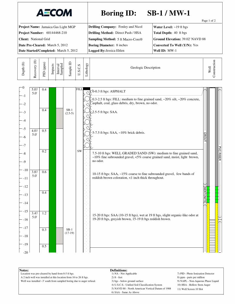
Project Name:
Project Number:
Date Pre-Cleared:
Date Started/Completed:
Drilling Company:
Drilling Method:
Sampling Method: Ground Elevation:
Total Depth:
Logged By:
0
-1
-2
-3
-4
-5
-6
-7
-8
-9
-10
-11
-12
-13
-14
-15
-16
-17
-18
-19
-20
Page 1 of 2D
epth
(ft
)
Rec
over
y (
ft)
PID
(ppm
)
Sam
ple
ID
Inte
rval
Lit
holo
gy
U.S
.C.S
Geologic Description
Boring ID:
Notes:
Jamaica Gas Light MGP
60144468-210
Fenley and Nicol
Impac
ts
Water Level:
Client:
Boring Diameter: Converted To Well (Y/N):
Well ID:
Wel
l
Definitions:
Sam
ple
d
1) NA - Not Applicable
2) ft - feet
3) bgs - below ground surface
4) U.S.C.S.- Unified Soil Classification System
8) ppm - parts per million
6) SAA - Same As Above
7) PID - Photo Ionization Detector
5) NAVD 88 - North American Vertical Datum of 1988
9) NAPL - Non-Aqueous Phase Liquid
5 ft Macro-Core®
Const
ruct
ion
National Grid
Direct Push / HSA
10) HSA - Hollow Stem Auger
11) Well Screen 10 Slot
0-0.3 ft bgs: ASPHALT
0.3-2.5 ft bgs: FILL: medium to fine grained sand, ~20% silt, ~20% concrete,asphalt, coal, glass debris, dry, brown, no odor.
2.5-5 ft bgs: SAA.
5-7.5 ft bgs: SAA, ~10% brick debris.
7.5-10 ft bgs: WELL GRADED SAND (SW): medium to fine grained sand,~10% fine subrounded gravel, <5% coarse grained sand, moist, light brown,no odor.
10-15 ft bgs: SAA, ~15% coarse to fine subrounded gravel, few bands ofreddish brown coloration, <1 inch thick throughout.
15-20 ft bgs: SAA (10-15 ft bgs), wet at 19 ft bgs, slight organic-like odor at19-20 ft bgs, greyish brown, 15-19 ft bgs reddish brown.
0.4
0.4
0.5
0.2
0.6
0.4
1.2
0.3
0.5
5.0'/5.0'
4.0'/5.0'
3.8'/5.0'
3.4'/5.0'
SB-1(2.5-5)
SB-1(17-19)
FILL
SW
SB-1 / MW-1
March 5, 2012
39.02' NAVD 88
40 ft bgs
Jessica Ehlen
March 5, 2012
~19 ft bgs
8 inches Yes
MW-1
Location was pre-cleared by hand from 0-5 ft bgs.
A 2 inch well was installed at this location from 16 to 26 ft bgs.
Well was installed ~3' south from sampled boring due to auger refusal.

Project Name:
Project Number:
Date Pre-Cleared:
Date Started/Completed:
Drilling Company:
Drilling Method:
Sampling Method: Ground Elevation:
Total Depth:
Logged By:
-20
-21
-22
-23
-24
-25
-26
-27
-28
-29
-30
-31
-32
-33
-34
-35
-36
-37
-38
-39
-40
Page 2 of 2D
epth
(ft
)
Rec
over
y (
ft)
PID
(ppm
)
Sam
ple
ID
Inte
rval
Lit
holo
gy
U.S
.C.S
Geologic Description
Boring ID:
Notes:
Jamaica Gas Light MGP
60144468-210
Fenley and Nicol
Impac
ts
Water Level:
Client:
Boring Diameter: Converted To Well (Y/N):
Well ID:
Wel
l
Definitions:
Sam
ple
d
1) NA - Not Applicable
2) ft - feet
3) bgs - below ground surface
4) U.S.C.S.- Unified Soil Classification System
8) ppm - parts per million
6) SAA - Same As Above
7) PID - Photo Ionization Detector
5) NAVD 88 - North American Vertical Datum of 1988
9) NAPL - Non-Aqueous Phase Liquid
5 ft Macro-Core®
Const
ruct
ion
National Grid
Direct Push / HSA
10) HSA - Hollow Stem Auger
11) Well Screen 10 Slot
20-25 ft bgs: WELL GRADED SAND (SW): medium to fine grained sand,~10% coarse grained sand, <5 % fine subrounded gravel, wet, light brown toreddish brown, no odor.
25-30 ft bgs: WELL GRADED SAND (SW): coarse to fine grained sand,~5% fine subrounded gravel, wet, light brown, no odor.
30- 35 ft bgs:SAA.
35-40 ft bgs: SAA, brown.
END OF BORING 40 ft bgs
1.8
0.3
1.1
0.5
1.1
0.4
0.5
0.5
5.0'/5.0'
5.0'/5.0'
5.0'/5.0'
3.8'/5.0'
SB-1(37.5-40)
SB-1 / MW-1
March 5, 2012
39.02' NAVD 88
40 ft bgs
Jessica Ehlen
March 5, 2012
~19 ft bgs
8 inches Yes
MW-1
Location was pre-cleared by hand from 0-5 ft bgs.
A 2 inch well was installed at this location from 16 to 26 ft bgs.
Well was installed ~3' south from sampled boring due to auger refusal.
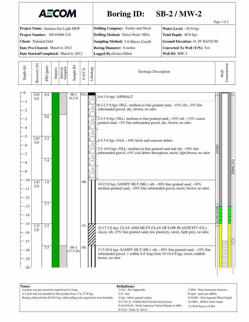
Project Name:
Project Number:
Date Pre-Cleared:
Date Started/Completed:
Drilling Company:
Drilling Method:
Sampling Method: Ground Elevation:
Total Depth:
Logged By:
0
-1
-2
-3
-4
-5
-6
-7
-8
-9
-10
-11
-12
-13
-14
-15
-16
-17
-18
-19
-20
Page 1 of 2D
epth
(ft
)
Rec
over
y (
ft)
PID
(ppm
)
Sam
ple
ID
Inte
rval
Lit
holo
gy
U.S
.C.S
Geologic Description
Boring ID:
Notes:
Jamaica Gas Light MGP
60144468-210
Fenley and Nicol
Impac
ts
Water Level:
Client:
Boring Diameter: Converted To Well (Y/N):
Well ID:
Wel
l
Definitions:
Sam
ple
d
1) NA - Not Applicable
2) ft - feet
3) bgs - below ground surface
4) U.S.C.S.- Unified Soil Classification System
8) ppm - parts per million
6) SAA - Same As Above
7) PID - Photo Ionization Detector
5) NAVD 88 - North American Vertical Datum of 1988
9) NAPL - Non-Aqueous Phase Liquid
5 ft Macro-Core®
Const
ruct
ion
National Grid
Direct Push / HSA
10) HSA - Hollow Stem Auger
11) Well Screen 10 Slot
0-0.3 ft bgs: ASPHALT
0.3-2.5 ft bgs: FILL: medium to fine grained sand, ~15% silt, ~5% finesubrounded gravel, dry, brown, no odor.
2.5-5 ft bgs: FILL: medium to fine grained sand, ~15% silt, ~15% coarsegrained sand, ~5% fine subrounded gravel, dry, brown, no odor.
5-5.5 ft bgs: SAA, ~10% brick and concrete debris.
5.5-10 ft bgs: FILL: medium to fine grained sand and silt, ~10% finesubrounded gravel, <5% coal debris throughout, moist, light brown, no odor.
10-15 ft bgs: SANDY SILT (ML): silt, ~30% fine grained sand, ~10%medium grained sand, ~10% fine subrounded gravel, moist, brown, no odor.
15-17.5 ft bgs: CLAY AND SILTY CLAY OF LOW PLASTICITY (CL):clayey silt, <5% fine grained sand, low plasticity, moist, light grey, no odor.
17.5-20 ft bgs: SANDY SILT (ML): silt, ~30% fine grained sand, ~15% finesubrounded gravel, 1 cobble 0.4' long from 19-19.4 ft bgs, moist, reddishbrown, no odor.
0.9
0.6
5.2
3.4
1.8
1.7
2.5
3.5
5.0'/5.0'
3.0'/5.0'
3.4'/5.0'
3.2'/5.0'
SB-2(0-2.5)
SB-2(17.5-20)
FILL
ML
CL
ML
SB-2 / MW-2
March 6, 2012
41.38' NAVD 88
40 ft bgs
Jessica Ehlen
March 6, 2012
~20 ft bgs
8 inches Yes
MW-2
Location was pre-cleared by hand from 0-5 ft bgs.
A 2 inch well was installed at this location from 17 to 27 ft bgs.
Boring collapsed from 40-29 ft bgs while pulling rods augers/rods from borehole.
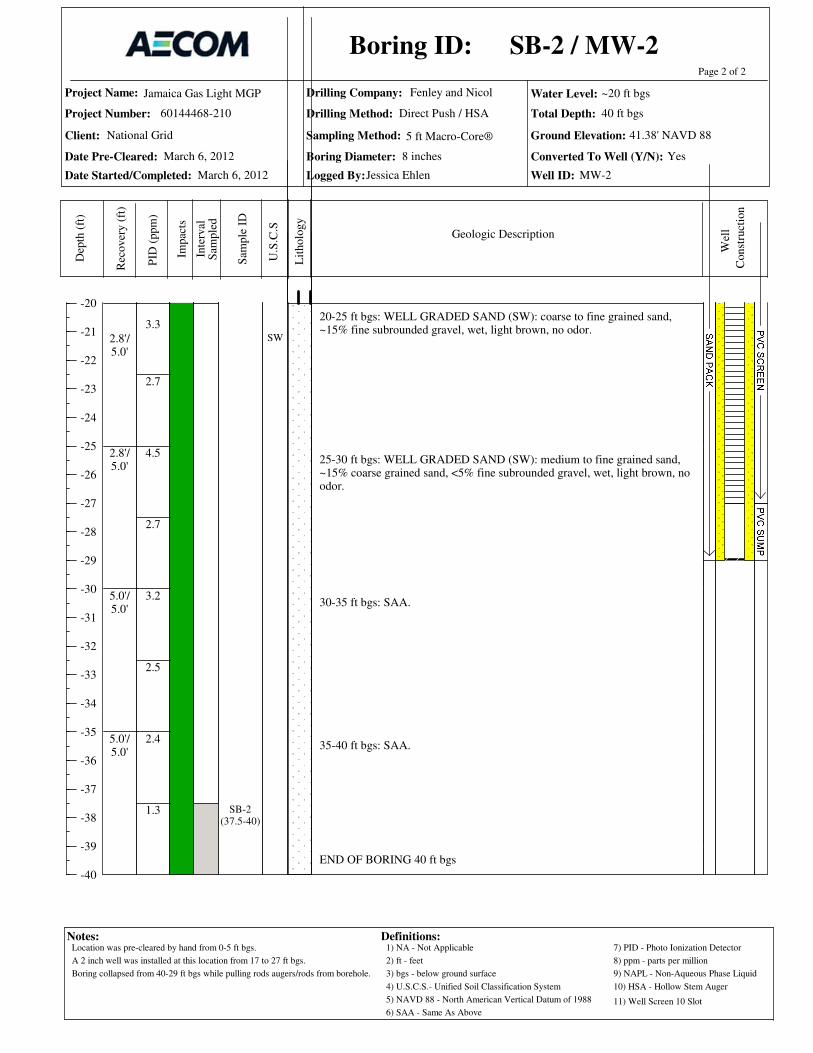
Project Name:
Project Number:
Date Pre-Cleared:
Date Started/Completed:
Drilling Company:
Drilling Method:
Sampling Method: Ground Elevation:
Total Depth:
Logged By:
-20
-21
-22
-23
-24
-25
-26
-27
-28
-29
-30
-31
-32
-33
-34
-35
-36
-37
-38
-39
-40
Page 2 of 2D
epth
(ft
)
Rec
over
y (
ft)
PID
(ppm
)
Sam
ple
ID
Inte
rval
Lit
holo
gy
U.S
.C.S
Geologic Description
Boring ID:
Notes:
Jamaica Gas Light MGP
60144468-210
Fenley and Nicol
Impac
ts
Water Level:
Client:
Boring Diameter: Converted To Well (Y/N):
Well ID:
Wel
l
Definitions:
Sam
ple
d
1) NA - Not Applicable
2) ft - feet
3) bgs - below ground surface
4) U.S.C.S.- Unified Soil Classification System
8) ppm - parts per million
6) SAA - Same As Above
7) PID - Photo Ionization Detector
5) NAVD 88 - North American Vertical Datum of 1988
9) NAPL - Non-Aqueous Phase Liquid
5 ft Macro-Core®
Const
ruct
ion
National Grid
Direct Push / HSA
10) HSA - Hollow Stem Auger
11) Well Screen 10 Slot
20-25 ft bgs: WELL GRADED SAND (SW): coarse to fine grained sand,~15% fine subrounded gravel, wet, light brown, no odor.
25-30 ft bgs: WELL GRADED SAND (SW): medium to fine grained sand,~15% coarse grained sand, <5% fine subrounded gravel, wet, light brown, noodor.
30-35 ft bgs: SAA.
35-40 ft bgs: SAA.
END OF BORING 40 ft bgs
3.3
2.7
4.5
2.7
3.2
2.5
2.4
1.3
2.8'/5.0'
2.8'/5.0'
5.0'/5.0'
5.0'/5.0'
SB-2(37.5-40)
SW
SB-2 / MW-2
March 6, 2012
41.38' NAVD 88
40 ft bgs
Jessica Ehlen
March 6, 2012
~20 ft bgs
8 inches Yes
MW-2
Location was pre-cleared by hand from 0-5 ft bgs.
A 2 inch well was installed at this location from 17 to 27 ft bgs.
Boring collapsed from 40-29 ft bgs while pulling rods augers/rods from borehole.
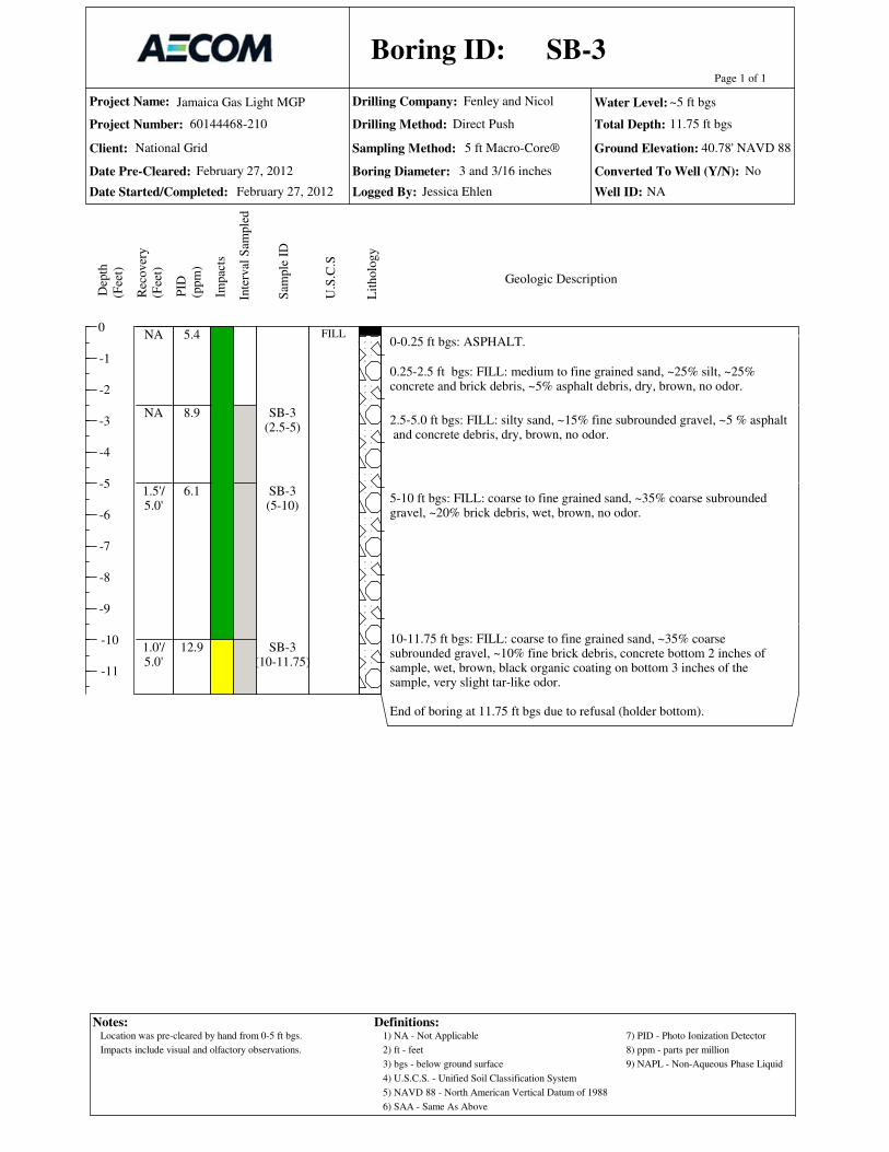
Project Name:
Project Number:
Date Pre-Cleared:
Date Started/Completed:
Drilling Company:
Drilling Method:
Sampling Method: Ground Elevation:
Total Depth:
Logged By:
0
-1
-2
-3
-4
-5
-6
-7
-8
-9
-10
-11
Page 1 of 1
Dep
th
(Fee
t)
Rec
over
y
(Fee
t)
PID
(ppm
)
Sam
ple
ID
Inte
rval
Sam
ple
d
Lit
holo
gy
U.S
.C.S
Geologic Description
Boring ID:
Jamaica Gas Light MGP
60144468-210
Fenley and Nicol
Impac
ts
Water Level:
Client:
Boring Diameter: Converted To Well (Y/N):
Well ID:
National Grid 5 ft Macro-Core®
Notes: Definitions:1) NA - Not Applicable
2) ft - feet
3) bgs - below ground surface
4) U.S.C.S. - Unified Soil Classification System
5) NAVD 88 - North American Vertical Datum of 1988
6) SAA - Same As Above
7) PID - Photo Ionization Detector
8) ppm - parts per million
9) NAPL - Non-Aqueous Phase Liquid
No
NA
Direct Push
0-0.25 ft bgs: ASPHALT.
0.25-2.5 ft bgs: FILL: medium to fine grained sand, ~25% silt, ~25%concrete and brick debris, ~5% asphalt debris, dry, brown, no odor.
2.5-5.0 ft bgs: FILL: silty sand, ~15% fine subrounded gravel, ~5 % asphalt and concrete debris, dry, brown, no odor.
5-10 ft bgs: FILL: coarse to fine grained sand, ~35% coarse subroundedgravel, ~20% brick debris, wet, brown, no odor.
10-11.75 ft bgs: FILL: coarse to fine grained sand, ~35% coarsesubrounded gravel, ~10% fine brick debris, concrete bottom 2 inches ofsample, wet, brown, black organic coating on bottom 3 inches of thesample, very slight tar-like odor.
End of boring at 11.75 ft bgs due to refusal (holder bottom).
5.4
8.9
6.1
12.9
NA
NA
1.5'/5.0'
1.0'/5.0'
SB-3(2.5-5)
SB-3(5-10)
SB-3(10-11.75)
FILL
SB-3
February 27, 2012
40.78' NAVD 88
11.75 ft bgs
Jessica Ehlen
February 27, 2012
~5 ft bgs
3 and 3/16 inches
Location was pre-cleared by hand from 0-5 ft bgs.
Impacts include visual and olfactory observations.

Project Name:
Project Number:
Date Pre-Cleared:
Date Started/Completed:
Drilling Company:
Drilling Method:
Sampling Method: Ground Elevation:
Total Depth:
Logged By:
0
-1
-2
-3
-4
-5
-6
-7
-8
-9
-10
-11
-12
-13
Page 1 of 1
Dep
th
(Fee
t)
Rec
over
y
(Fee
t)
PID
(ppm
)
Sam
ple
ID
Inte
rval
Sam
ple
d
Lit
holo
gy
U.S
.C.S
Geologic Description
Boring ID:
Jamaica Gas Light MGP
60144468-210
Fenley and Nicol
Impac
ts
Water Level:
Client:
Boring Diameter: Converted To Well (Y/N):
Well ID:
National Grid 5 ft Macro-Core®
Notes: Definitions:1) NA - Not Applicable
2) ft - feet
3) bgs - below ground surface
4) U.S.C.S. - Unified Soil Classification System
5) NAVD 88 - North American Vertical Datum of 1988
6) SAA - Same As Above
7) PID - Photo Ionization Detector
8) ppm - parts per million
9) NAPL - Non-Aqueous Phase Liquid
No
NA
Direct Push
0-0.2 ft bgs: ASPHALT0.2-1.5 ft bgs: FILL: medium to fine grained sand, ~25% silt, ~25% brickand concrete debris, brown, dry, no odor.
1.5-3 ft bgs: SAA, moist.
3- 5 ft bgs: FILL: sandy silt, ~15% fine concrete and brick debris, moist,brown, no odor.
5-8.5 ft bgs: FILL: sandy silt, ~10% fine subrounded gravel, ~10% clay,moist, brown, slight organic odor.
8.5-10 ft bgs: FILL: wood debris (piling), creosote-like odor.
10-13 ft bgs: FILL: sandy silt, ~30% clay, ~10% wood, concrete, and brickdebris, low plasticity, wet, 2 inches of concrete at bottom of sample, slighttar-like odor.
End of boring at 13 ft bgs due to refusal (holder bottom).
4.2
6.1
7.5
7.3
24.5
14.9
5.0'/5.0'
3.3'/5.0'
1.8'/5.0'
SB-4(3-5)
SB-4(5-8.5)
SB-4(8.5-10)
SB-4(10-13)
FILL
SB-4
February 27, 2012
42.28' NAVD 88
13 ft bgs
Jessica Ehlen
February 27, 2012
~10 ft bgs
3 and 3/16 inches
Location was pre-cleared by hand from 0-5 ft bgs.
Impacts include visual and olfactory observations.

Project Name:
Project Number:
Date Pre-Cleared:
Date Started/Completed:
Drilling Company:
Drilling Method:
Sampling Method: Ground Elevation:
Total Depth:
Logged By:
0
-1
-2
-3
-4
-5
-6
-7
-8
-9
-10
-11
-12
-13
-14
-15
-16
-17
-18
-19
-20
Page 1 of 2D
epth
(ft
)
Rec
over
y (
ft)
PID
(ppm
)
Sam
ple
ID
Inte
rval
Lit
holo
gy
U.S
.C.S
Geologic Description
Boring ID:
Notes:
Jamaica Gas Light MGP
60144468-210
Fenley and Nicol
Impac
ts
Water Level:
Client:
Boring Diameter: Converted To Well (Y/N):
Well ID:
Wel
l
Definitions:
Sam
ple
d
1) NA - Not Applicable
2) ft - feet
3) bgs - below ground surface
4) U.S.C.S.- Unified Soil Classification System
8) ppm - parts per million
6) SAA - Same As Above
7) PID - Photo Ionization Detector
5) NAVD 88 - North American Vertical Datum of 1988
9) NAPL - Non-Aqueous Phase Liquid
5 ft Macro-Core®
Const
ruct
ion
National Grid
Direct Push / HSA
10) HSA - Hollow Stem Auger
11) Well Screen 10 Slot
0-0.35 ft bgs: FILL: silty sand, ~35% coarse subangular gravel, dry, brown,no odor.
0.35-2.5 ft bgs: FILL: SAA, ~20% brick and concrete debris, dry, brown, noodor.
2.5-5 ft bgs: FILL: medium to fine grained sand, ~15% fine subroundedgravel, <5% brick and concrete debris, dry, brown, no odor.
5-7.5 ft bgs: FILL: medium to fine grained sand, ~10% brick debris, ~15%coarse subrounded gravel, moist, light brown, no odor.
7.5-10 ft bgs: WELL GRADED SAND (SW): medium to fine grained sand,<5% fine subrounded gravel, moist, light brown, no odor.
10-15 ft bgs: WELL GRADED SAND (SW): coarse to fine grained sand,~20% coarse to fine subrounded gravel, moist, light brown, no odor.
15-20 ft bgs: SAA, less gravel ~10%, dark brown from 16-17 ft bgs.
0.9
0.9
1.0
0.7
0.9
1.2
1.3
5.0'/5.0'
3.2'/5.0'
2.0'/5.0'
5.0'/5.0'
SS-5A(0-2")
SB-5(2.5-5)
FILL
SW
SB-5 / MW-5
March 8/12, 2012
43.63' NAVD 88
40 ft bgs
Jessica Ehlen
March 8, 2012
~24 ft bgs
8 inches Yes
MW-5
Location was pre-cleared by hand from 0-5 ft bgs.
Impacts include visual and olfactory observations.
A 2 inch well was installed at this location from 21 to 31 ft bgs.
Boring collapsed from 40-33 ft bgs while augering.

Project Name:
Project Number:
Date Pre-Cleared:
Date Started/Completed:
Drilling Company:
Drilling Method:
Sampling Method: Ground Elevation:
Total Depth:
Logged By:
-20
-21
-22
-23
-24
-25
-26
-27
-28
-29
-30
-31
-32
-33
-34
-35
-36
-37
-38
-39
-40
Page 2 of 2D
epth
(ft
)
Rec
over
y (
ft)
PID
(ppm
)
Sam
ple
ID
Inte
rval
Lit
holo
gy
U.S
.C.S
Geologic Description
Boring ID:
Notes:
Jamaica Gas Light MGP
60144468-210
Fenley and Nicol
Impac
ts
Water Level:
Client:
Boring Diameter: Converted To Well (Y/N):
Well ID:
Wel
l
Definitions:
Sam
ple
d
1) NA - Not Applicable
2) ft - feet
3) bgs - below ground surface
4) U.S.C.S.- Unified Soil Classification System
8) ppm - parts per million
6) SAA - Same As Above
7) PID - Photo Ionization Detector
5) NAVD 88 - North American Vertical Datum of 1988
9) NAPL - Non-Aqueous Phase Liquid
5 ft Macro-Core®
Const
ruct
ion
National Grid
Direct Push / HSA
10) HSA - Hollow Stem Auger
11) Well Screen 10 Slot
20-25 ft bgs: SAA, wet at 24 ft bgs, ~5% fine subrounded gravel.
25-30 ft bgs: WELL GRADED SAND (SW): medium to fine grained sand,~10% coarse grained sand, ~10% fine subrounded gravel, wet, light brown,no odor.
30-35 ft bgs: SAA.
35-4 ft bgs: SAA, ~10% coarse subrounded gravel, wet, brown, no odor.
END OF BORING 40 ft bgs
0.6
0.7
0.3
0.6
0.1
0.0
0.8
0.0
0.0
5.0'/5.0'
5.0'/5.0'
5.0'/5.0'
5.0'/5.0'
SB-5(22-24)
SB-5(37.5-40)
SB-5 / MW-5
March 8/12, 2012
43.63' NAVD 88
40 ft bgs
Jessica Ehlen
March 8, 2012
~24 ft bgs
8 inches Yes
MW-5
Location was pre-cleared by hand from 0-5 ft bgs.
Impacts include visual and olfactory observations.
A 2 inch well was installed at this location from 21 to 31 ft bgs.
Boring collapsed from 40-33 ft bgs while augering.

Project Name:
Project Number:
Date Pre-Cleared:
Date Started/Completed:
Drilling Company:
Drilling Method:
Sampling Method: Ground Elevation:
Total Depth:
Logged By:
0
-1
-2
-3
-4
-5
-6
-7
-8
-9
-10
-11
-12
-13
-14
-15
-16
-17
-18
-19
-20
Page 1 of 2
Dep
th
(Fee
t)
Rec
over
y
(Fee
t)
PID
(ppm
)
Sam
ple
ID
Inte
rval
Sam
ple
d
Lit
holo
gy
U.S
.C.S
Geologic Description
Boring ID:
Jamaica Gas Light MGP
60144468-210
Fenley and Nicol
Impac
ts
Water Level:
Client:
Boring Diameter: Converted To Well (Y/N):
Well ID:
National Grid 5 ft Macro-Core®
Notes: Definitions:1) NA - Not Applicable
2) ft - feet
3) bgs - below ground surface
4) U.S.C.S. - Unified Soil Classification System
5) NAVD 88 - North American Vertical Datum of 1988
6) SAA - Same As Above
7) PID - Photo Ionization Detector
8) ppm - parts per million
9) NAPL - Non-Aqueous Phase Liquid
No
NA
Direct Push
0-0.21 ft bgs: ASPHALT0.21-0.42 ft bgs: FILL: sandy gravel/gravelly sand base, no fines. GW/SW,grey / black, fine to medium grained sand, medium dense, dry.0.42-3.5 ft bgs: FILL: fine to medium grained sand, ~10% coarse grainedsand, ~10% angular gravel, <5% cobble, medium density, dry, brown.
3.5-7 ft bgs: SAA.
7-9.5 ft bgs: FILL: sandy silt, slightly plastic, ~25% fine to medium grained sand, soft, moist, reddish brown.
9.5-10 ft bgs: FILL: brick/concrete fragments.
10-15 ft bgs: WELL GRADED SAND (SW): fine to medium grained sand,~10% coarse angular sand, ~5 % fine rounded gravel, medium dense, dry,orangish brown.
15-20 ft bgs: SAA, dark and light banding ~1/8-1/4 inch width.
0.7
0.9
1.4
1.3
0.7
1.1
2.5'/3.5'
2.5'/3.5'
3.0'/3.0'
2.5'/5.0'
3.0'/5.0'
SB-6(1-3.5)
FILL
SW
SB-6
February 22, 2012
43.79' NAVD 88
40 ft bgs
Hallie Garrett
February 22, 2012
~24 ft bgs
3 and 3/16 inches
Location was pre-cleared by hand from 0-5 ft bgs.
Impacts include visual and olfactory observations.
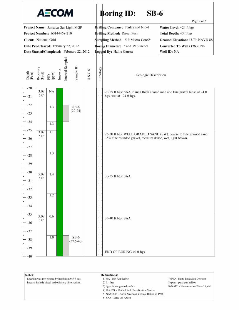
Project Name:
Project Number:
Date Pre-Cleared:
Date Started/Completed:
Drilling Company:
Drilling Method:
Sampling Method: Ground Elevation:
Total Depth:
Logged By:
-20
-21
-22
-23
-24
-25
-26
-27
-28
-29
-30
-31
-32
-33
-34
-35
-36
-37
-38
-39
-40
Page 2 of 2
Dep
th
(Fee
t)
Rec
over
y
(Fee
t)
PID
(ppm
)
Sam
ple
ID
Inte
rval
Sam
ple
d
Lit
holo
gy
U.S
.C.S
Geologic Description
Boring ID:
Jamaica Gas Light MGP
60144468-210
Fenley and Nicol
Impac
ts
Water Level:
Client:
Boring Diameter: Converted To Well (Y/N):
Well ID:
National Grid 5 ft Macro-Core®
Notes: Definitions:1) NA - Not Applicable
2) ft - feet
3) bgs - below ground surface
4) U.S.C.S. - Unified Soil Classification System
5) NAVD 88 - North American Vertical Datum of 1988
6) SAA - Same As Above
7) PID - Photo Ionization Detector
8) ppm - parts per million
9) NAPL - Non-Aqueous Phase Liquid
No
NA
Direct Push
20-25 ft bgs: SAA, 6 inch thick coarse sand and fine gravel lense at 24 ftbgs, wet at ~24 ft bgs.
25-30 ft bgs: WELL GRADED SAND (SW): coarse to fine grained sand,~5% fine rounded gravel, medium dense, wet, light brown.
30-35 ft bgs: SAA.
35-40 ft bgs: SAA.
END OF BORING 40 ft bgs
NA
1.3
1.3
1.1
1.3
1.4
1.2
0.6
1.0
3.0'/5.0'
3.0'/5.0'
5.0'/5.0'
5.0'/5.0'
SB-6(22-24)
SB-6(37.5-40)
SB-6
February 22, 2012
43.79' NAVD 88
40 ft bgs
Hallie Garrett
February 22, 2012
~24 ft bgs
3 and 3/16 inches
Location was pre-cleared by hand from 0-5 ft bgs.
Impacts include visual and olfactory observations.

Project Name:
Project Number:
Date Pre-Cleared:
Date Started/Completed:
Drilling Company:
Drilling Method:
Sampling Method: Ground Elevation:
Total Depth:
Logged By:
0
-1
-2
-3
-4
-5
-6
-7
-8
-9
-10
-11
-12
-13
-14
-15
-16
-17
-18
-19
-20
Page 1 of 2
Dep
th
(Fee
t)
Rec
over
y
(Fee
t)
PID
(ppm
)
Sam
ple
ID
Inte
rval
Sam
ple
d
Lit
holo
gy
U.S
.C.S
Geologic Description
Boring ID:
Jamaica Gas Light MGP
60144468-210
Fenley and Nicol
Impac
ts
Water Level:
Client:
Boring Diameter: Converted To Well (Y/N):
Well ID:
National Grid 5 ft Macro-Core®
Notes: Definitions:1) NA - Not Applicable
2) ft - feet
3) bgs - below ground surface
4) U.S.C.S. - Unified Soil Classification System
5) NAVD 88 - North American Vertical Datum of 1988
6) SAA - Same As Above
7) PID - Photo Ionization Detector
8) ppm - parts per million
9) NAPL - Non-Aqueous Phase Liquid
No
NA
Direct Push
0-0.2 ft bgs: ASPHALT0.2-1.2 ft bgs: FILL: medium to fine grained sand, ~25% silt, ~30% brickand concrete debris, dry, brown, no odor.
1.2-2 ft bgs: FILL: CONCRETE SLAB2-2.5 ft bgs: SAA (0.2-1.2).
2.5-5 ft bgs: SAA.
5-6 ft bgs: SAA.
6-10 ft bgs: FILL: medium to fine grained sand, ~30% silt, ~10% finesubrounded gravel, 2 pieces of coal from 8.5-9 ft bgs, <5% plant fibers(roots), dry, brown, no odor.
10-15 ft bgs: SILTY SAND (SM): medium to fine grained sand and silt,<5% fine rounded gravel, dry, tan, dark brown from 13.5'-13.8', no odor.
15-20 ft bgs: SAA, ~15% fine rounded gravel, dry, orange-tan, dark brownfrom 18'-19', no odor.
2.8
2.1
1.5
1.0
0.9
1.6
1.0
5.0'/5.0'
5.0'/5.0'
2.8'/5.0'
2.0'/5.0'
SB-7(0-2.5)
FILL
SM
SB-7
February 22, 2012
45.49' NAVD 88
40 ft bgs
Jessica Ehlen
February 22, 2012
~24 ft bgs
3 and 3/16 inches
Location was pre-cleared by hand from 0-5 ft bgs.
Impacts include visual and olfactory observations.

Project Name:
Project Number:
Date Pre-Cleared:
Date Started/Completed:
Drilling Company:
Drilling Method:
Sampling Method: Ground Elevation:
Total Depth:
Logged By:
-20
-21
-22
-23
-24
-25
-26
-27
-28
-29
-30
-31
-32
-33
-34
-35
-36
-37
-38
-39
-40
Page 2 of 2
Dep
th
(Fee
t)
Rec
over
y
(Fee
t)
PID
(ppm
)
Sam
ple
ID
Inte
rval
Sam
ple
d
Lit
holo
gy
U.S
.C.S
Geologic Description
Boring ID:
Jamaica Gas Light MGP
60144468-210
Fenley and Nicol
Impac
ts
Water Level:
Client:
Boring Diameter: Converted To Well (Y/N):
Well ID:
National Grid 5 ft Macro-Core®
Notes: Definitions:1) NA - Not Applicable
2) ft - feet
3) bgs - below ground surface
4) U.S.C.S. - Unified Soil Classification System
5) NAVD 88 - North American Vertical Datum of 1988
6) SAA - Same As Above
7) PID - Photo Ionization Detector
8) ppm - parts per million
9) NAPL - Non-Aqueous Phase Liquid
No
NA
Direct Push
20-21.5 ft bgs: SAA, dry, dark brown from 21-21.3 ft bgs.
21.5-24 ft bgs: WELL GRADED SAND (SW): medium to fine grainedsand, ~10% coarse grained sand, moist, tan, orange band from 23'-23.2', noodor.
24-25 ft bgs: SAA, wet.
25-30 ft bgs: WELL GRADED SAND (SW): coarse to fine grained sand,~10% fine rounded gravel, wet, tan, few orange bands at 27.5'-28.7', noodor.
30-35 ft bgs: WELL GRADED SAND (SW): coarse to fine grained sand,~25% fine rounded gravel, wet, light brown, no odor.
35-40 ft bgs: SAA.
END OF BORING 40 ft bgs.
0.8
0.6
1.0
0.6
0.5
1.0
0.6
0.6
2.0
4.2'/5.0'
2.8'/5.0'
5.0'/5.0'
5.0'/5.0'
SB-7(21.5-24)
SB-7(37.5-40)+ms/msd
SW
SB-7
February 22, 2012
45.49' NAVD 88
40 ft bgs
Jessica Ehlen
February 22, 2012
~24 ft bgs
3 and 3/16 inches
Location was pre-cleared by hand from 0-5 ft bgs.
Impacts include visual and olfactory observations.

Project Name:
Project Number:
Date Pre-Cleared:
Date Started/Completed:
Drilling Company:
Drilling Method:
Sampling Method: Ground Elevation:
Total Depth:
Logged By:
0
-1
-2
-3
-4
-5
-6
-7
-8
-9
-10
-11
-12
-13
-14
-15
-16
-17
-18
-19
-20
Page 1 of 3
Dep
th
(Fee
t)
Rec
over
y
(Fee
t)
PID
(ppm
)
Sam
ple
ID
Inte
rval
Sam
ple
d
Lit
holo
gy
U.S
.C.S
Geologic Description
Boring ID:
Jamaica Gas Light MGP
60144468-210
Fenley and Nicol
Impac
ts
Water Level:
Client:
Boring Diameter: Converted To Well (Y/N):
Well ID:
National Grid 5 ft Macro-Core®
Notes: Definitions:1) NA - Not Applicable
2) ft - feet
3) bgs - below ground surface
4) U.S.C.S. - Unified Soil Classification System
5) NAVD 88 - North American Vertical Datum of 1988
6) SAA - Same As Above
7) PID - Photo Ionization Detector
8) ppm - parts per million
9) NAPL - Non-Aqueous Phase Liquid
No
NA
Direct Push
0-0.15 ft bgs: ASPHALT
0.15-2.5 ft bgs: FILL: silty sand and coarse subangular gravel, <5% brickand concrete debris, <5% coal debris, dry, brown, no odor.
2.5-5 ft bgs: FILL: medium to fine grained sand, ~30% silt, ~30% brick and mortar debris, ~10% coarse subangular gravel, <5% coal debris, <5% ash,dry, brown, no odor.
5-7.5 ft bgs: SAA.
7.5-9 ft bgs: FILL: medium to fine grained sand, ~15% silt, ~10% brick and mortar debris, <5% coal debris and ash, dry, brown, no odor.
9-10 ft bgs: FILL: brick and mortar debris, ~25% medium to fine grainedsand, <5% coal debris and ash, dry, grey, no odor.
10-15 ft bgs: SAA (9-10), ~10% ash, ~5% broken glass.
15-17 ft bgs: SAA (10-15), slight tar-like coating and slight tar-like odorfrom 16.5 ft bgs to 17 ft bgs, crushed brick ~5 inches thick at 17 ft bgs.
17-19 ft bgs: FILL: fine grained sand and silt, ~25% coarse subroundedgravel, <5% metal debris, dry, greyish brown, slight naphthalene-like odor.
19-20 ft bgs: WELL GRADED SAND (SW): medium to fine grained sand,<5% fine subrounded gravel, moist, light brown, no odor.
1.8
1.9
2.1
2.8
1.5
45.3
30.4
3.5
5.0'/5.0'
2.5'/5.0'
2.2'/5.0'
4.7'/5.0'
SB-8(2.5-5)
SB-8(15-17)
FILL
SW
SB-8
March 7, 2012
44.37' NAVD 88
45 ft bgs
Jessica Ehlen
March 1, 2012
~24.5 ft bgs
8 Inches
Location was pre-cleared by hand from 0-5 ft bgs.
Impacts include visual and olfactory observations.

Project Name:
Project Number:
Date Pre-Cleared:
Date Started/Completed:
Drilling Company:
Drilling Method:
Sampling Method: Ground Elevation:
Total Depth:
Logged By:
-20
-21
-22
-23
-24
-25
-26
-27
-28
-29
-30
-31
-32
-33
-34
-35
-36
-37
-38
-39
Page 2 of 3
Dep
th
(Fee
t)
Rec
over
y
(Fee
t)
PID
(ppm
)
Sam
ple
ID
Inte
rval
Sam
ple
d
Lit
holo
gy
U.S
.C.S
Geologic Description
Boring ID:
Jamaica Gas Light MGP
60144468-210
Fenley and Nicol
Impac
ts
Water Level:
Client:
Boring Diameter: Converted To Well (Y/N):
Well ID:
National Grid 5 ft Macro-Core®
Notes: Definitions:1) NA - Not Applicable
2) ft - feet
3) bgs - below ground surface
4) U.S.C.S. - Unified Soil Classification System
5) NAVD 88 - North American Vertical Datum of 1988
6) SAA - Same As Above
7) PID - Photo Ionization Detector
8) ppm - parts per million
9) NAPL - Non-Aqueous Phase Liquid
No
NA
Direct Push
20-25 ft bgs: WELL GRADED SAND (SW): medium to fine grained sand,~10% coarse grained sand, moist, wet at 24.5 ft bgs, light brown, few bands of orange brown coloration, no odor.
25-30 ft bgs: SAA, brown (no banding).
30-35 ft bgs: SAA (25-30), ~10% coarse subrounded gravel.
35-40 ft bgs: No Recovery, rock in sample bit.
2.2
0.8
0.6
1.5
1.0
NA
2.5'/5.0'
2.6'/5.0'
3.3'/5.0'
0.0'/5.0'
SB-8(20-25)
NR
SB-8
March 7, 2012
44.37' NAVD 88
45 ft bgs
Jessica Ehlen
March 1, 2012
~24.5 ft bgs
8 Inches
Location was pre-cleared by hand from 0-5 ft bgs.
Impacts include visual and olfactory observations.
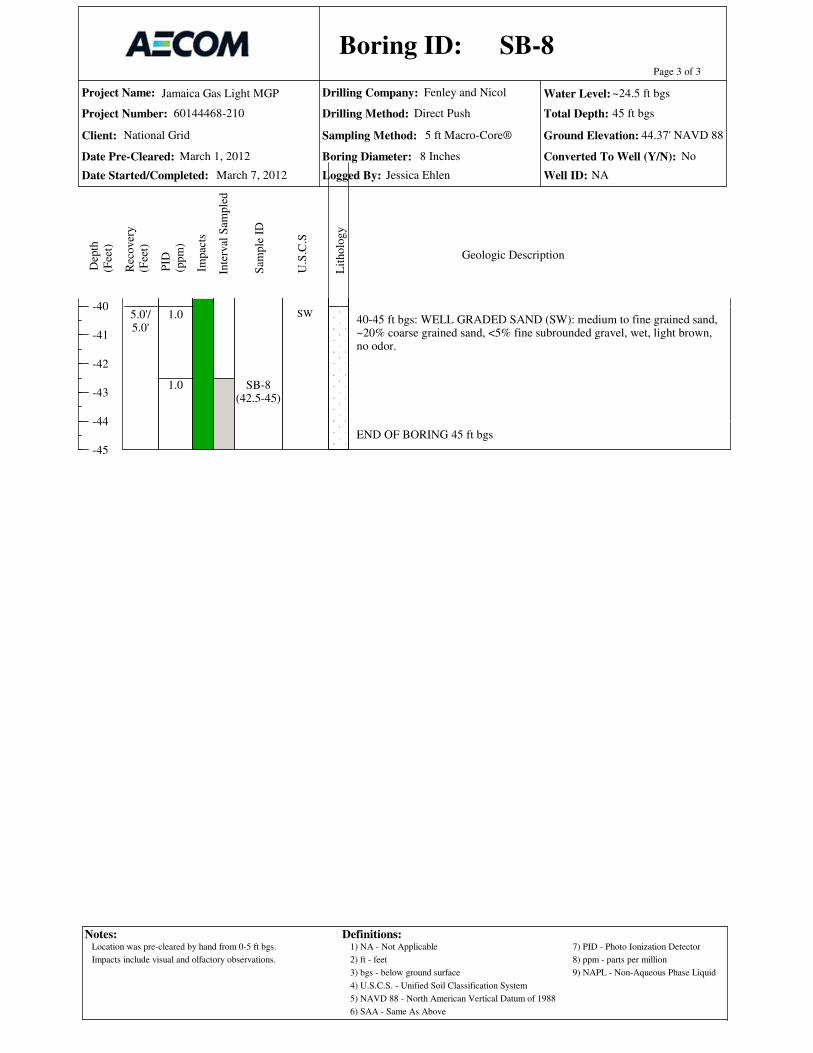
Project Name:
Project Number:
Date Pre-Cleared:
Date Started/Completed:
Drilling Company:
Drilling Method:
Sampling Method: Ground Elevation:
Total Depth:
Logged By:
-40
-41
-42
-43
-44
-45
Page 3 of 3
Dep
th
(Fee
t)
Rec
over
y
(Fee
t)
PID
(ppm
)
Sam
ple
ID
Inte
rval
Sam
ple
d
Lit
holo
gy
U.S
.C.S
Geologic Description
Boring ID:
Jamaica Gas Light MGP
60144468-210
Fenley and Nicol
Impac
ts
Water Level:
Client:
Boring Diameter: Converted To Well (Y/N):
Well ID:
National Grid 5 ft Macro-Core®
Notes: Definitions:1) NA - Not Applicable
2) ft - feet
3) bgs - below ground surface
4) U.S.C.S. - Unified Soil Classification System
5) NAVD 88 - North American Vertical Datum of 1988
6) SAA - Same As Above
7) PID - Photo Ionization Detector
8) ppm - parts per million
9) NAPL - Non-Aqueous Phase Liquid
No
NA
Direct Push
40-45 ft bgs: WELL GRADED SAND (SW): medium to fine grained sand,~20% coarse grained sand, <5% fine subrounded gravel, wet, light brown,no odor.
END OF BORING 45 ft bgs
1.0
1.0
5.0'/5.0'
SB-8(42.5-45)
SW
SB-8
March 7, 2012
44.37' NAVD 88
45 ft bgs
Jessica Ehlen
March 1, 2012
~24.5 ft bgs
8 Inches
Location was pre-cleared by hand from 0-5 ft bgs.
Impacts include visual and olfactory observations.

Project Name:
Project Number:
Date Pre-Cleared:
Date Started/Completed:
Drilling Company:
Drilling Method:
Sampling Method: Ground Elevation:
Total Depth:
Logged By:
0
-1
-2
-3
-4
-5
-6
-7
-8
-9
-10
-11
-12
-13
-14
-15
-16
-17
-18
-19
-20
Page 1 of 2D
epth
(ft
)
Rec
over
y (
ft)
PID
(ppm
)
Sam
ple
ID
Inte
rval
Lit
holo
gy
U.S
.C.S
Geologic Description
Boring ID:
Notes:
Jamaica Gas Light MGP
60144468-210
Fenley and Nicol
Impac
ts
Water Level:
Client:
Boring Diameter: Converted To Well (Y/N):
Well ID:
Wel
l
Definitions:
Sam
ple
d
1) NA - Not Applicable
2) ft - feet
3) bgs - below ground surface
4) U.S.C.S.- Unified Soil Classification System
8) ppm - parts per million
6) SAA - Same As Above
7) PID - Photo Ionization Detector
5) NAVD 88 - North American Vertical Datum of 1988
9) NAPL - Non-Aqueous Phase Liquid
5 ft Macro-Core®
Const
ruct
ion
National Grid
Direct Push / HSA
10) HSA - Hollow Stem Auger
11) Well Screen 10 Slot
0-0.3 ft bgs: ASPHALT0.3-2.5 ft bgs: FILL: medium to fine grained sand, ~20% silt, ~10% concreteand asphalt debris, ~10% fine subrounded gravel, brown, no odor.
2.5-5 ft bgs: FILL: medium to fine grained sand, ~20% silt, ~5% concretedebris, ~10% fine subrounded gravel, brown, no odor.
5-10 ft bgs: SAA.
10-15 ft bgs: WELL GRADED SAND (SW): coarse to fine grained sand,~10% fine subrounded gravel, light brown, layer of silt from 13-13.5 ft bgs,~30% clay, low plasticity, light brown, no odor.
15-20 ft bgs: WELL GRADED SAND (SW): medium to fine grained sand,~10% fine subrounded gravel, ~5% plant fibers, light brown, no odor.
0.7
0.6
6.0
2.8
0.8
0.4
0.7
0.4
5.0'/5.0'
3.0'/5.0'
3.4'/5.0'
3.7'/5.0'
FILL
SW
SB-8A / MW-3
March 7, 2012
44.56 NAVD 88
35 ft bgs
Jessica Ehlen
March 7, 2012
~24.5 ft bgs
8 Inches Yes
MW-3
Location was pre-cleared by hand from 0-5 ft bgs.
Impacts include visual and olfactory observations.
A 2 inch well was installed from 20.5 to 30.5 ft bgs.
Borehole collapsed from 35-32.5 ft bgs while augering/pulling rods from borehole.
No samples were collected from this borehole.

Project Name:
Project Number:
Date Pre-Cleared:
Date Started/Completed:
Drilling Company:
Drilling Method:
Sampling Method: Ground Elevation:
Total Depth:
Logged By:
-20
-21
-22
-23
-24
-25
-26
-27
-28
-29
-30
-31
-32
-33
-34
-35
Page 2 of 2D
epth
(ft
)
Rec
over
y (
ft)
PID
(ppm
)
Sam
ple
ID
Inte
rval
Lit
holo
gy
U.S
.C.S
Geologic Description
Boring ID:
Notes:
Jamaica Gas Light MGP
60144468-210
Fenley and Nicol
Impac
ts
Water Level:
Client:
Boring Diameter: Converted To Well (Y/N):
Well ID:
Wel
l
Definitions:
Sam
ple
d
1) NA - Not Applicable
2) ft - feet
3) bgs - below ground surface
4) U.S.C.S.- Unified Soil Classification System
8) ppm - parts per million
6) SAA - Same As Above
7) PID - Photo Ionization Detector
5) NAVD 88 - North American Vertical Datum of 1988
9) NAPL - Non-Aqueous Phase Liquid
5 ft Macro-Core®
Const
ruct
ion
National Grid
Direct Push / HSA
10) HSA - Hollow Stem Auger
11) Well Screen 10 Slot
20-23.5 ft bgs: SAA.
23.5-25 ft bgs: WELL GRADED SAND (SW): coarse to fine grained sand,~20% fine subrounded gravel, light brown, wet, no odor.
25-30 ft bgs: SAA.
30-35 ft bgs: SAA.
END OF BORING 35 ft bgs
0.3
0.3
0.4
0.5
0.3
0.9
0.6
3.0'/5.0'
5.0'/5.0'
5.0'/5.0'
SB-8A / MW-3
March 7, 2012
44.56 NAVD 88
35 ft bgs
Jessica Ehlen
March 7, 2012
~24.5 ft bgs
8 Inches Yes
MW-3
Location was pre-cleared by hand from 0-5 ft bgs.
Impacts include visual and olfactory observations.
A 2 inch well was installed from 20.5 to 30.5 ft bgs.
Borehole collapsed from 35-32.5 ft bgs while augering/pulling rods from borehole.
No samples were collected from this borehole.

Project Name:
Project Number:
Date Pre-Cleared:
Date Started/Completed:
Drilling Company:
Drilling Method:
Sampling Method: Ground Elevation:
Total Depth:
Logged By:
0
-1
-2
-3
-4
-5
-6
-7
-8
-9
-10
-11
-12
-13
-14
-15
-16
-17
-18
-19
-20
Page 1 of 2
Dep
th
(Fee
t)
Rec
over
y
(Fee
t)
PID
(ppm
)
Sam
ple
ID
Inte
rval
Sam
ple
d
Lit
holo
gy
U.S
.C.S
Geologic Description
Boring ID:
Jamaica Gas Light MGP
60144468-210
Fenley and Nicol
Impac
ts
Water Level:
Client:
Boring Diameter: Converted To Well (Y/N):
Well ID:
National Grid 5 ft Macro-Core®
Notes: Definitions:1) NA - Not Applicable
2) ft - feet
3) bgs - below ground surface
4) U.S.C.S. - Unified Soil Classification System
5) NAVD 88 - North American Vertical Datum of 1988
6) SAA - Same As Above
7) PID - Photo Ionization Detector
8) ppm - parts per million
9) NAPL - Non-Aqueous Phase Liquid
No
NA
Direct Push
0-0.13 ft bgs: ASPHALT
0.13-0.25 ft bgs: FILL: gravelly sand/sand gravel base, dry.
0.25-5 ft bgs: FILL: sandy gravel, fine angular gravel, coal cinders, dry,grey, black, brown.
5-9 ft bgs: SAA.
9-10 ft bgs: FILL: fine to coarse angular grained sand, ~10% fine gravel,wet, reddish brown, slight tar-like odor.
10-13 ft bgs: FILL: sandy gravel, fine subangular to angular gravel, wet,slight tar-like odor.
13-13.5 ft bgs: FILL: black, tar coated wood, wet.13.5-14 ft bgs: FILL: red brick layer.
14-15 ft bgs: WELL GRADED SAND (SW): fine to coarse grained sand,with fine well rounded gravel, medium dense, moist, orange-brown, slighttar-like odor.
15-17.5 ft bgs: SAA.
17.5-20 ft bgs: WELL GRADED SAND (SW): coarse to fine grained sandwith well rounded gravel, medium dense, moist, 1/2" thick banding, slighttar-like odor.
ND
1.1
9.3
5.3
678.2
336.9
216.3
5.0'/5.0'
4.0'/5.0'
3.0'/5.0'
2.5'/5.0'
SB-9(2.5-5)
SB-9(10-13.5)
FILL
SW
SB-9
February 23, 2012
46.28' NAVD 88
40 ft bgs
Hallie Garrett
February 23, 2012
~26 ft bgs
3 3/16 Inches
Location was pre-cleared by hand from 0-5 ft bgs.
Impacts include visual and olfactory observations.

Project Name:
Project Number:
Date Pre-Cleared:
Date Started/Completed:
Drilling Company:
Drilling Method:
Sampling Method: Ground Elevation:
Total Depth:
Logged By:
-20
-21
-22
-23
-24
-25
-26
-27
-28
-29
-30
-31
-32
-33
-34
-35
-36
-37
-38
-39
-40
Page 2 of 2
Dep
th
(Fee
t)
Rec
over
y
(Fee
t)
PID
(ppm
)
Sam
ple
ID
Inte
rval
Sam
ple
d
Lit
holo
gy
U.S
.C.S
Geologic Description
Boring ID:
Jamaica Gas Light MGP
60144468-210
Fenley and Nicol
Impac
ts
Water Level:
Client:
Boring Diameter: Converted To Well (Y/N):
Well ID:
National Grid 5 ft Macro-Core®
Notes: Definitions:1) NA - Not Applicable
2) ft - feet
3) bgs - below ground surface
4) U.S.C.S. - Unified Soil Classification System
5) NAVD 88 - North American Vertical Datum of 1988
6) SAA - Same As Above
7) PID - Photo Ionization Detector
8) ppm - parts per million
9) NAPL - Non-Aqueous Phase Liquid
No
NA
Direct Push
20-25 ft bgs: SAA, orange-brown, slight tar-like odor.
25-30 ft bgs: SAA, wet at 26 ft bgs, slight tar-like odor.
30-33 ft bgs: SAA.
33-35 ft bgs: SAA, ~40% coarse subangular gravel, wet, no odor.
35-40 ft bgs: SAA.
END OF BORING 40 ft bgs
37.5
41.4
6.2
8.1
8.2
9.2
2.5'/5.0'
3.0'/5.0'
3.0'/5.0'
5.0'/5.0'
SB-9(37.5-40)
SB-9
February 23, 2012
46.28' NAVD 88
40 ft bgs
Hallie Garrett
February 23, 2012
~26 ft bgs
3 3/16 Inches
Location was pre-cleared by hand from 0-5 ft bgs.
Impacts include visual and olfactory observations.

Project Name:
Project Number:
Date Pre-Cleared:
Date Started/Completed:
Drilling Company:
Drilling Method:
Sampling Method: Ground Elevation:
Total Depth:
Logged By:
0
-1
-2
-3
-4
-5
-6
-7
-8
-9
-10
-11
-12
-13
-14
-15
-16
-17
-18
-19
-20
Page 1 of 2
Dep
th
(Fee
t)
Rec
over
y
(Fee
t)
PID
(ppm
)
Sam
ple
ID
Inte
rval
Sam
ple
d
Lit
holo
gy
U.S
.C.S
Geologic Description
Boring ID:
Jamaica Gas Light MGP
60144468-210
Fenley and Nicol
Impac
ts
Water Level:
Client:
Boring Diameter: Converted To Well (Y/N):
Well ID:
National Grid 5 ft Macro-Core®
Notes: Definitions:1) NA - Not Applicable
2) ft - feet
3) bgs - below ground surface
4) U.S.C.S. - Unified Soil Classification System
5) NAVD 88 - North American Vertical Datum of 1988
6) SAA - Same As Above
7) PID - Photo Ionization Detector
8) ppm - parts per million
9) NAPL - Non-Aqueous Phase Liquid
No
NA
Direct Push
0-0.08 ft bgs: ASPHALT0.08-0.16 ft bgs: FILL: gravelly sand.
0.16-5 ft bgs: FILL: medium to fine grained sand, ~5% coarse grained sandand fine rounded gravel, medium dense, dry, brown.
5-7.5 ft bgs: SAA.
7.5-10 ft bgs: SAA.
10-12.5 ft bgs: SAA.
12.5-15 ft bgs: WELL GRADED SAND (SW): medium to fine grainedsand, ~10% coarse grained sand, ~5% fine gravel, dry, brown (stained toblack), tar coating on sand grains, strong tar-like odor.
15-17.5 ft bgs: POORLY GRADED SAND (SP): fine grained sand, ~5%fine gravel, dry, stained to black, slight tar coating on sand grains, strongtar-like odor.
17.5-20 ft bgs: WELL GRADED SAND (SW): coarse to fine grained sand,~5% fine angular gravel, medium dense, dry, brown with moderate staining of black tar, strong tar-like odor.
4.9
5.2
5.9
4.1
8.1
306.4
11.0
4.2
5.0'/5.0'
3.5'/5.0'
3.33'/5.0'
3.0'/5.0'
SB-10(1-2.5)
SB-10(12.5-15)
FILL
SW
SP
SW
SB-10
February 23, 2012
46.84' NAVD 88
40 ft bgs
Hallie Garrett
February 23, 2012
~26.2 ft bgs
3 and 3/16 inches
Location was pre-cleared by hand from 0-5 ft bgs.
Impacts include visual and olfactory observations.

Project Name:
Project Number:
Date Pre-Cleared:
Date Started/Completed:
Drilling Company:
Drilling Method:
Sampling Method: Ground Elevation:
Total Depth:
Logged By:
-20
-21
-22
-23
-24
-25
-26
-27
-28
-29
-30
-31
-32
-33
-34
-35
-36
-37
-38
-39
-40
Page 2 of 2
Dep
th
(Fee
t)
Rec
over
y
(Fee
t)
PID
(ppm
)
Sam
ple
ID
Inte
rval
Sam
ple
d
Lit
holo
gy
U.S
.C.S
Geologic Description
Boring ID:
Jamaica Gas Light MGP
60144468-210
Fenley and Nicol
Impac
ts
Water Level:
Client:
Boring Diameter: Converted To Well (Y/N):
Well ID:
National Grid 5 ft Macro-Core®
Notes: Definitions:1) NA - Not Applicable
2) ft - feet
3) bgs - below ground surface
4) U.S.C.S. - Unified Soil Classification System
5) NAVD 88 - North American Vertical Datum of 1988
6) SAA - Same As Above
7) PID - Photo Ionization Detector
8) ppm - parts per million
9) NAPL - Non-Aqueous Phase Liquid
No
NA
Direct Push
20-23.5 ft bgs: SAA, no staining, light brown, to orange brown, banded 1/4-1 inch, slight tar-like odor.
23.5-25 ft bgs: WELL GRADED SAND (SW): coarse to fine grained sand,~10% fine gravel, dry, medium brown, banded with heavy staining, slighttar-like odor.
25-26.2 ft bgs: SAA.
26.2-26.8 ft bgs: SAA, wet, moderate staining, slight to moderate tar-likeodor.
26.8-30 ft bgs: WELL GRADED SAND (SW): coarse to fine grained sand,~10% rounded gravel, wet, no staining or odor.
30-35 ft bgs: SAA, no staining or odor.
35-40 ft bgs: SAA, no staining or odor.
END OF BORING 40 ft bgs
6.0
3.2
9.0
136.4
2.8
9.2
7.0
9.4
5.7
3.33'/5.0'
3.67'/5.0'
5.0'/5.0'
5.0'/5.0'
SB-10(26-27.5)
SB-10(37.5-40)
SB-10
February 23, 2012
46.84' NAVD 88
40 ft bgs
Hallie Garrett
February 23, 2012
~26.2 ft bgs
3 and 3/16 inches
Location was pre-cleared by hand from 0-5 ft bgs.
Impacts include visual and olfactory observations.

Project Name:
Project Number:
Date Pre-Cleared:
Date Started/Completed:
Drilling Company:
Drilling Method:
Sampling Method: Ground Elevation:
Total Depth:
Logged By:
0
-1
-2
-3
-4
-5
-6
-7
-8
-9
-10
-11
-12
-13
-14
-15
-16
-17
-18
-19
-20
Page 1 of 2
Dep
th
(Fee
t)
Rec
over
y
(Fee
t)
PID
(ppm
)
Sam
ple
ID
Inte
rval
Sam
ple
d
Lit
holo
gy
U.S
.C.S
Geologic Description
Boring ID:
Jamaica Gas Light MGP
60144468-210
Fenley and Nicol
Impac
ts
Water Level:
Client:
Boring Diameter: Converted To Well (Y/N):
Well ID:
National Grid 5 ft Macro-Core®
Notes: Definitions:1) NA - Not Applicable
2) ft - feet
3) bgs - below ground surface
4) U.S.C.S. - Unified Soil Classification System
5) NAVD 88 - North American Vertical Datum of 1988
6) SAA - Same As Above
7) PID - Photo Ionization Detector
8) ppm - parts per million
9) NAPL - Non-Aqueous Phase Liquid
No
NA
Direct Push
0-0.3 ft bgs: FILL: silty sand ~20% subangular coarse gravel, brown, noodor.0.3-2.5 ft bgs: FILL: medium to fine grained sand, ~10% coarse grainedsand, ~10% subrounded gravel, dry, light brown, no odor.
2.5- 6 ft bgs: SAA.
6-10 ft bgs: WELL GRADED SAND (SW): medium to fine grained sand,~20% coarse grained sand, ~10% subrounded coarse gravel, dry, lightbrown, no odor.
10-15 ft bgs: SAA, moist at 11.5 ft bgs, few bands of orange-browncoloration.
15-20 ft bgs: SAA.
0.2
0.4
0.8
0.5
0.5
0.6
0.7
6.0'/6.0'
2.0'/5.0'
3.4'/5.0'
3.6'/5.0'
SB-11(0-2.5)
FILL
SW
SB-11
February 28, 2012
45.13' NAVD 88
40 ft bgs
Jessica Ehlen
February 28, 2012
~27 ft bgs
3 and 3/16 inches
Location was pre-cleared by hand from 0-5 ft bgs.
Impacts include visual and olfactory observations.

Project Name:
Project Number:
Date Pre-Cleared:
Date Started/Completed:
Drilling Company:
Drilling Method:
Sampling Method: Ground Elevation:
Total Depth:
Logged By:
-20
-21
-22
-23
-24
-25
-26
-27
-28
-29
-30
-31
-32
-33
-34
-35
-36
-37
-38
-39
-40
Page 2 of 2
Dep
th
(Fee
t)
Rec
over
y
(Fee
t)
PID
(ppm
)
Sam
ple
ID
Inte
rval
Sam
ple
d
Lit
holo
gy
U.S
.C.S
Geologic Description
Boring ID:
Jamaica Gas Light MGP
60144468-210
Fenley and Nicol
Impac
ts
Water Level:
Client:
Boring Diameter: Converted To Well (Y/N):
Well ID:
National Grid 5 ft Macro-Core®
Notes: Definitions:1) NA - Not Applicable
2) ft - feet
3) bgs - below ground surface
4) U.S.C.S. - Unified Soil Classification System
5) NAVD 88 - North American Vertical Datum of 1988
6) SAA - Same As Above
7) PID - Photo Ionization Detector
8) ppm - parts per million
9) NAPL - Non-Aqueous Phase Liquid
No
NA
Direct Push
20-22 ft bgs: SAA.
22-24.5 ft bgs: SAA, more orange banding.
24.5-25 ft bgs: WELL GRADED SAND (SW): medium to fine grainedsand, ~25% fine subrounded gravel, moist, brown, no odor.
25-27 ft bgs: SAA, moist, light brown, no odor.
27-30 ft bgs: WELL GRADED SAND (SW): medium to fine grained sand,~20% coarse grained sand, ~15% fine subrounded gravel, wet at ~27 ft bgs, brown, no odor.
30-35 ft bgs: SAA, light brown to brown.
35-40 ft bgs: SAA, brown.
END OF BORING 40 ft bgs
1.1
1.1
0.6
1.1
0.4
2.2
1.3
5.0'/5.0'
5.0'/5.0'
5.0'/5.0'
5.0'/5.0'
SB-11(25-27)
SB-11(35-40)
SB-11
February 28, 2012
45.13' NAVD 88
40 ft bgs
Jessica Ehlen
February 28, 2012
~27 ft bgs
3 and 3/16 inches
Location was pre-cleared by hand from 0-5 ft bgs.
Impacts include visual and olfactory observations.
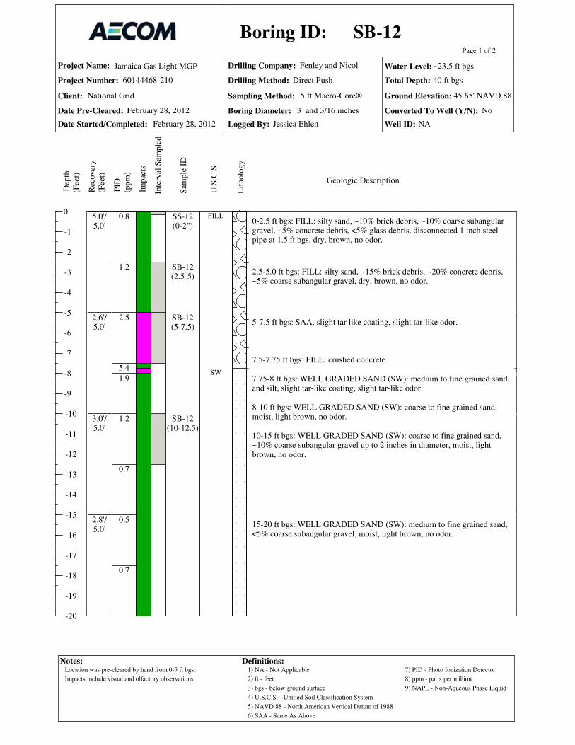
Project Name:
Project Number:
Date Pre-Cleared:
Date Started/Completed:
Drilling Company:
Drilling Method:
Sampling Method: Ground Elevation:
Total Depth:
Logged By:
0
-1
-2
-3
-4
-5
-6
-7
-8
-9
-10
-11
-12
-13
-14
-15
-16
-17
-18
-19
-20
Page 1 of 2
Dep
th
(Fee
t)
Rec
over
y
(Fee
t)
PID
(ppm
)
Sam
ple
ID
Inte
rval
Sam
ple
d
Lit
holo
gy
U.S
.C.S
Geologic Description
Boring ID:
Jamaica Gas Light MGP
60144468-210
Fenley and Nicol
Impac
ts
Water Level:
Client:
Boring Diameter: Converted To Well (Y/N):
Well ID:
National Grid 5 ft Macro-Core®
Notes: Definitions:1) NA - Not Applicable
2) ft - feet
3) bgs - below ground surface
4) U.S.C.S. - Unified Soil Classification System
5) NAVD 88 - North American Vertical Datum of 1988
6) SAA - Same As Above
7) PID - Photo Ionization Detector
8) ppm - parts per million
9) NAPL - Non-Aqueous Phase Liquid
No
NA
Direct Push
0-2.5 ft bgs: FILL: silty sand, ~10% brick debris, ~10% coarse subangulargravel, ~5% concrete debris, <5% glass debris, disconnected 1 inch steelpipe at 1.5 ft bgs, dry, brown, no odor.
2.5-5.0 ft bgs: FILL: silty sand, ~15% brick debris, ~20% concrete debris,~5% coarse subangular gravel, dry, brown, no odor.
5-7.5 ft bgs: SAA, slight tar like coating, slight tar-like odor.
7.5-7.75 ft bgs: FILL: crushed concrete.
7.75-8 ft bgs: WELL GRADED SAND (SW): medium to fine grained sandand silt, slight tar-like coating, slight tar-like odor.
8-10 ft bgs: WELL GRADED SAND (SW): coarse to fine grained sand,moist, light brown, no odor.
10-15 ft bgs: WELL GRADED SAND (SW): coarse to fine grained sand,~10% coarse subangular gravel up to 2 inches in diameter, moist, lightbrown, no odor.
15-20 ft bgs: WELL GRADED SAND (SW): medium to fine grained sand,<5% coarse subangular gravel, moist, light brown, no odor.
0.8
1.2
2.5
5.4
1.9
1.2
0.7
0.5
0.7
5.0'/5.0'
2.6'/5.0'
3.0'/5.0'
2.8'/5.0'
SS-12(0-2")
SB-12(2.5-5)
SB-12(5-7.5)
SB-12(10-12.5)
FILL
SW
SB-12
February 28, 2012
45.65' NAVD 88
40 ft bgs
Jessica Ehlen
February 28, 2012
~23.5 ft bgs
3 and 3/16 inches
Location was pre-cleared by hand from 0-5 ft bgs.
Impacts include visual and olfactory observations.
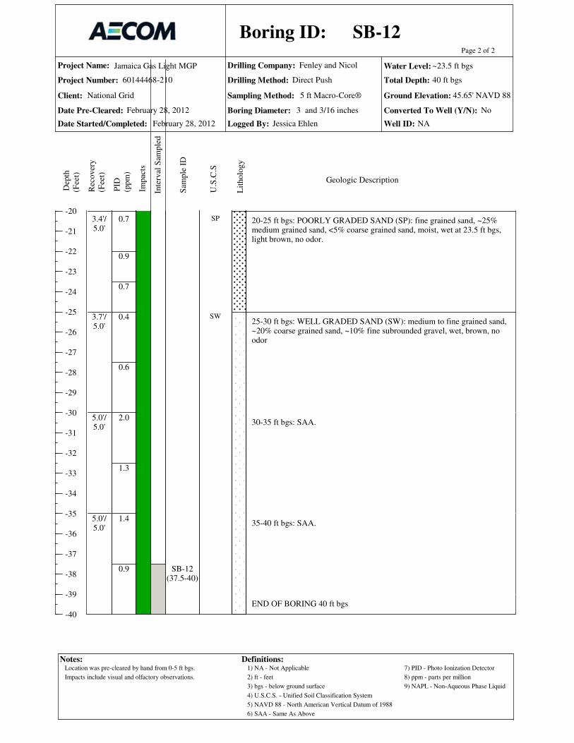
Project Name:
Project Number:
Date Pre-Cleared:
Date Started/Completed:
Drilling Company:
Drilling Method:
Sampling Method: Ground Elevation:
Total Depth:
Logged By:
-20
-21
-22
-23
-24
-25
-26
-27
-28
-29
-30
-31
-32
-33
-34
-35
-36
-37
-38
-39
-40
Page 2 of 2
Dep
th
(Fee
t)
Rec
over
y
(Fee
t)
PID
(ppm
)
Sam
ple
ID
Inte
rval
Sam
ple
d
Lit
holo
gy
U.S
.C.S
Geologic Description
Boring ID:
Jamaica Gas Light MGP
60144468-210
Fenley and Nicol
Impac
ts
Water Level:
Client:
Boring Diameter: Converted To Well (Y/N):
Well ID:
National Grid 5 ft Macro-Core®
Notes: Definitions:1) NA - Not Applicable
2) ft - feet
3) bgs - below ground surface
4) U.S.C.S. - Unified Soil Classification System
5) NAVD 88 - North American Vertical Datum of 1988
6) SAA - Same As Above
7) PID - Photo Ionization Detector
8) ppm - parts per million
9) NAPL - Non-Aqueous Phase Liquid
No
NA
Direct Push
20-25 ft bgs: POORLY GRADED SAND (SP): fine grained sand, ~25%medium grained sand, <5% coarse grained sand, moist, wet at 23.5 ft bgs,light brown, no odor.
25-30 ft bgs: WELL GRADED SAND (SW): medium to fine grained sand,~20% coarse grained sand, ~10% fine subrounded gravel, wet, brown, noodor
30-35 ft bgs: SAA.
35-40 ft bgs: SAA.
END OF BORING 40 ft bgs
0.7
0.9
0.7
0.4
0.6
2.0
1.3
1.4
0.9
3.4'/5.0'
3.7'/5.0'
5.0'/5.0'
5.0'/5.0'
SB-12(37.5-40)
SP
SW
SB-12
February 28, 2012
45.65' NAVD 88
40 ft bgs
Jessica Ehlen
February 28, 2012
~23.5 ft bgs
3 and 3/16 inches
Location was pre-cleared by hand from 0-5 ft bgs.
Impacts include visual and olfactory observations.

Project Name:
Project Number:
Date Pre-Cleared:
Date Started/Completed:
Drilling Company:
Drilling Method:
Sampling Method: Ground Elevation:
Total Depth:
Logged By:
0
-1
-2
-3
-4
-5
-6
-7
-8
-9
-10
-11
-12
-13
-14
-15
-16
-17
-18
-19
-20
Page 1 of 2D
epth
(ft
)
Rec
over
y (
ft)
PID
(ppm
)
Sam
ple
ID
Inte
rval
Lit
holo
gy
U.S
.C.S
Geologic Description
Boring ID:
Notes:
Jamaica Gas Light MGP
60144468-210
Fenley and Nicol
Impac
ts
Water Level:
Client:
Boring Diameter: Converted To Well (Y/N):
Well ID:
Wel
l
Definitions:
Sam
ple
d
1) NA - Not Applicable
2) ft - feet
3) bgs - below ground surface
4) U.S.C.S.- Unified Soil Classification System
8) ppm - parts per million
6) SAA - Same As Above
7) PID - Photo Ionization Detector
5) NAVD 88 - North American Vertical Datum of 1988
9) NAPL - Non-Aqueous Phase Liquid
5 ft Macro-Core®
Const
ruct
ion
National Grid
Direct Push / HSA
10) HSA - Hollow Stem Auger
11) Well Screen 10 Slot
0-2.5 ft bgs: FILL: medium to fine grained sand, ~10% coarse grained sand,~10% subrounded gravel, ~10% silt, dry, brown, no odor.
2.5-5 ft bgs: SAA.
5-7.5 ft bgs: FILL: medium to fine grained sand, ~10% silt, ~10% finesubrounded gravel,<5% plant fibers, moist, brown, no odor.
7.5-10 ft bgs: WELL GRADED SAND (SW): coarse to fine grained sand,~15% fine subrounded gravel, moist, orange-brown, no odor.
10-15 ft bgs: SAA, some reddish brown banding.
15-20 ft bgs: WELL GRADED SAND (SW): medium to fine grained sand,~10% coarse grained sand, <5% fine subrounded gravel, moist, light brown,few orange-brown bands, no odor.
0.1
0.2
1.2
1.0
2.3
2.3
4.2
3.9
5.0'/5.0'
3.3'/5.0'
3.2'/5.0'
4.4'/5.0'
SB-13(2.5-5)
FILL
SW
SB-13 / MW-6
February 29, 2012
46.32' NAVD 88
40 ft bgs
K. Barbour / J. Ehlen
February 28, 2012
~24.5 ft bgs
8 Inches Yes
MW-6
Location was pre-cleared by hand from 0-5 ft bgs.
Impacts include visual and olfactory observations.
A 2 inch well was installed at this location from 21.5-31.5 ft bgs.
Borehole collapsed from 40-33.5 ft bgs while pulling augers/rods from borehole.

Project Name:
Project Number:
Date Pre-Cleared:
Date Started/Completed:
Drilling Company:
Drilling Method:
Sampling Method: Ground Elevation:
Total Depth:
Logged By:
-20
-21
-22
-23
-24
-25
-26
-27
-28
-29
-30
-31
-32
-33
-34
-35
-36
-37
-38
-39
-40
Page 2 of 2D
epth
(ft
)
Rec
over
y (
ft)
PID
(ppm
)
Sam
ple
ID
Inte
rval
Lit
holo
gy
U.S
.C.S
Geologic Description
Boring ID:
Notes:
Jamaica Gas Light MGP
60144468-210
Fenley and Nicol
Impac
ts
Water Level:
Client:
Boring Diameter: Converted To Well (Y/N):
Well ID:
Wel
l
Definitions:
Sam
ple
d
1) NA - Not Applicable
2) ft - feet
3) bgs - below ground surface
4) U.S.C.S.- Unified Soil Classification System
8) ppm - parts per million
6) SAA - Same As Above
7) PID - Photo Ionization Detector
5) NAVD 88 - North American Vertical Datum of 1988
9) NAPL - Non-Aqueous Phase Liquid
5 ft Macro-Core®
Const
ruct
ion
National Grid
Direct Push / HSA
10) HSA - Hollow Stem Auger
11) Well Screen 10 Slot
20-25 ft bgs: SAA, more orange-brown banding, 1 coarse subangular gravelat 22 ft bgs, 2 inches in diameter, wet at 24.5 ft bgs.
25-30 ft bgs: SAA (15-20), orange-brown to brown, sandy silt layer 28.2-28.4 ft bgs.
30-32.5 ft bgs: SAA, no silt layer.
32.5-35 ft bgs: SILTY SAND (SM): silty fine sand, ~10% medium sand, <5% fine subrounded gravel, wet, brown, no odor.
35-40 ft bgs: WELL GRADED SAND (SW): medium to fine grained sand,~20% coarse grained sand, ~10% coarse subangular gravel, wet, brown, noodor.
END OF BORING 40 ft bgs
1.8
2.4
3.5
3.2
3.3
1.9
2.8
3.1
1.0
4.4'/5.0'
5.0'/5.0'
3.5'/5.0'
5.0'/5.0'
SB-13(22.5-24.5)
SB-13(37.5-40)
SM
SW
SB-13 / MW-6
February 29, 2012
46.32' NAVD 88
40 ft bgs
K. Barbour / J. Ehlen
February 28, 2012
~24.5 ft bgs
8 Inches Yes
MW-6
Location was pre-cleared by hand from 0-5 ft bgs.
Impacts include visual and olfactory observations.
A 2 inch well was installed at this location from 21.5-31.5 ft bgs.
Borehole collapsed from 40-33.5 ft bgs while pulling augers/rods from borehole.
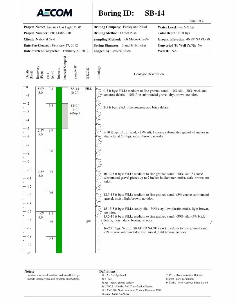
Project Name:
Project Number:
Date Pre-Cleared:
Date Started/Completed:
Drilling Company:
Drilling Method:
Sampling Method: Ground Elevation:
Total Depth:
Logged By:
0
-1
-2
-3
-4
-5
-6
-7
-8
-9
-10
-11
-12
-13
-14
-15
-16
-17
-18
-19
-20
Page 1 of 2
Dep
th
(Fee
t)
Rec
over
y
(Fee
t)
PID
(ppm
)
Sam
ple
ID
Inte
rval
Sam
ple
d
Lit
holo
gy
U.S
.C.S
Geologic Description
Boring ID:
Jamaica Gas Light MGP
60144468-210
Fenley and Nicol
Impac
ts
Water Level:
Client:
Boring Diameter: Converted To Well (Y/N):
Well ID:
National Grid 5 ft Macro-Core®
Notes: Definitions:1) NA - Not Applicable
2) ft - feet
3) bgs - below ground surface
4) U.S.C.S. - Unified Soil Classification System
5) NAVD 88 - North American Vertical Datum of 1988
6) SAA - Same As Above
7) PID - Photo Ionization Detector
8) ppm - parts per million
9) NAPL - Non-Aqueous Phase Liquid
No
NA
Direct Push
0-2 ft bgs: FILL: medium to fine grained sand, ~10% silt, ~20% brick andconcrete debris, ~10% fine subrounded gravel, dry, brown, no odor.
2-5 ft bgs: SAA, fine concrete and brick debris.
5-10 ft bgs: FILL: sand, ~35% silt, 1 coarse subrounded gravel ~2 inches in diameter at 5 ft bgs, moist, brown, no odor.
10-12.5 ft bgs: FILL: medium to fine grained sand, ~30% silt, 2 coarsesubrounded gravel pieces up to 2 inches in diameter, moist, dark brown, no odor.
12.5-15 ft bgs: FILL: medium to fine grained sand, <5% coarse subrounded gravel, moist, light brown, no odor.
15-15.5 ft bgs: FILL: sandy silt, ~30% clay, low plastic, moist, light brown, no odor.15.5-16 ft bgs: FILL: medium to fine grained sand, ~30% silt, <5% brickdebris, moist, dark brown, no odor.
16-20 ft bgs: WELL GRADED SAND (SW): medium to fine grained sand,<5% coarse subrounded gravel, moist, light brown, no odor.
3.8
3.8
3.9
3.0
0.5
0.6
1.1
0.6
0.8
5.0'/5.0'
2.5'/5.0'
2.5'/5.0'
4.0'/5.0'
SS-14(0-2")
SB-14(2-5)
+Dup 2
FILL
SW
SB-14
February 27, 2012
46.99' NAVD 88
40 ft bgs
Jessica Ehlen
February 27, 2012
~26.5 ft bgs
3 and 3/16 inches
Location was pre-cleared by hand from 0-5 ft bgs.
Impacts include visual and olfactory observations.

Project Name:
Project Number:
Date Pre-Cleared:
Date Started/Completed:
Drilling Company:
Drilling Method:
Sampling Method: Ground Elevation:
Total Depth:
Logged By:
-20
-21
-22
-23
-24
-25
-26
-27
-28
-29
-30
-31
-32
-33
-34
-35
-36
-37
-38
-39
-40
Page 2 of 2
Dep
th
(Fee
t)
Rec
over
y
(Fee
t)
PID
(ppm
)
Sam
ple
ID
Inte
rval
Sam
ple
d
Lit
holo
gy
U.S
.C.S
Geologic Description
Boring ID:
Jamaica Gas Light MGP
60144468-210
Fenley and Nicol
Impac
ts
Water Level:
Client:
Boring Diameter: Converted To Well (Y/N):
Well ID:
National Grid 5 ft Macro-Core®
Notes: Definitions:1) NA - Not Applicable
2) ft - feet
3) bgs - below ground surface
4) U.S.C.S. - Unified Soil Classification System
5) NAVD 88 - North American Vertical Datum of 1988
6) SAA - Same As Above
7) PID - Photo Ionization Detector
8) ppm - parts per million
9) NAPL - Non-Aqueous Phase Liquid
No
NA
Direct Push
20-20.75 ft bgs: SANDY SILT (ML): sandy silt, moist, light brown, noodor.
20.75-21 ft bgs: WELL GRADED SAND (SW): medium to fine grainedsand, ~10% mica schist pieces (black), moist, dark brown, no odor.
21-25 ft bgs: WELL GRADED SAND (SW): medium to fine grained sand,<5% fine subrounded gravel, moist, light brown, few bands of orange-redsand, no odor.
25-26 ft bgs: SILTY SAND (SM): silty sand, moist, light brown, no odor.
26-26.5 ft bgs: WELL GRADED SAND (SW): medium to fine grainedsand, ~20% coarse subangular gravel, moist, dark brown, no odor.
26.5-30 ft bgs: WELL GRADED SAND (SW): medium to fine grainedsand, ~10% coarse grained sand, ~10% fine subrounded gravel, wet,orange-brown, no odor.
30-35 ft bgs: WELL GRADED SAND (SW): coarse to fine grained sand,<5% fine subrounded gravel, wet, light brown, no odor.
35-40 ft bgs: SAA.
END OF BORING 40 ft bgs
3.7
0.5
0.7
3.5
0.4
1.2
2.0
1.1
1.8
2.1
4.7'/5.0'
5.0'/5.0'
5.0'/5.0'
5.0'/5.0'
SB-14(25-26.5)
SB-14(37.5-40)+ms/msd
ML
SW
SM
SW
SB-14
February 27, 2012
46.99' NAVD 88
40 ft bgs
Jessica Ehlen
February 27, 2012
~26.5 ft bgs
3 and 3/16 inches
Location was pre-cleared by hand from 0-5 ft bgs.
Impacts include visual and olfactory observations.
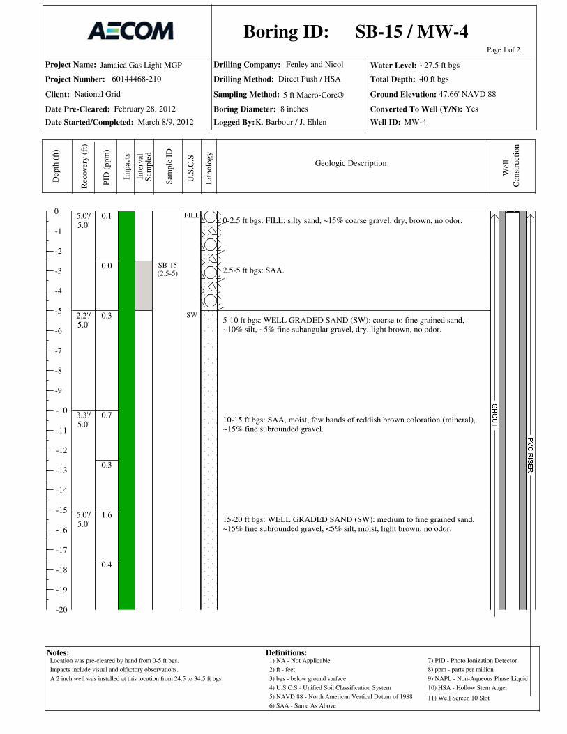
Project Name:
Project Number:
Date Pre-Cleared:
Date Started/Completed:
Drilling Company:
Drilling Method:
Sampling Method: Ground Elevation:
Total Depth:
Logged By:
0
-1
-2
-3
-4
-5
-6
-7
-8
-9
-10
-11
-12
-13
-14
-15
-16
-17
-18
-19
-20
Page 1 of 2D
epth
(ft
)
Rec
over
y (
ft)
PID
(ppm
)
Sam
ple
ID
Inte
rval
Lit
holo
gy
U.S
.C.S
Geologic Description
Boring ID:
Notes:
Jamaica Gas Light MGP
60144468-210
Fenley and Nicol
Impac
ts
Water Level:
Client:
Boring Diameter: Converted To Well (Y/N):
Well ID:
Wel
l
Definitions:
Sam
ple
d
1) NA - Not Applicable
2) ft - feet
3) bgs - below ground surface
4) U.S.C.S.- Unified Soil Classification System
8) ppm - parts per million
6) SAA - Same As Above
7) PID - Photo Ionization Detector
5) NAVD 88 - North American Vertical Datum of 1988
9) NAPL - Non-Aqueous Phase Liquid
5 ft Macro-Core®
Const
ruct
ion
National Grid
Direct Push / HSA
10) HSA - Hollow Stem Auger
11) Well Screen 10 Slot
0-2.5 ft bgs: FILL: silty sand, ~15% coarse gravel, dry, brown, no odor.
2.5-5 ft bgs: SAA.
5-10 ft bgs: WELL GRADED SAND (SW): coarse to fine grained sand,~10% silt, ~5% fine subangular gravel, dry, light brown, no odor.
10-15 ft bgs: SAA, moist, few bands of reddish brown coloration (mineral),~15% fine subrounded gravel.
15-20 ft bgs: WELL GRADED SAND (SW): medium to fine grained sand,~15% fine subrounded gravel, <5% silt, moist, light brown, no odor.
0.1
0.0
0.3
0.7
0.3
1.6
0.4
5.0'/5.0'
2.2'/5.0'
3.3'/5.0'
5.0'/5.0'
SB-15(2.5-5)
FILL
SW
SB-15 / MW-4
March 8/9, 2012
47.66' NAVD 88
40 ft bgs
K. Barbour / J. Ehlen
February 28, 2012
~27.5 ft bgs
8 inches Yes
MW-4
Location was pre-cleared by hand from 0-5 ft bgs.
Impacts include visual and olfactory observations.
A 2 inch well was installed at this location from 24.5 to 34.5 ft bgs.

Project Name:
Project Number:
Date Pre-Cleared:
Date Started/Completed:
Drilling Company:
Drilling Method:
Sampling Method: Ground Elevation:
Total Depth:
Logged By:
-20
-21
-22
-23
-24
-25
-26
-27
-28
-29
-30
-31
-32
-33
-34
-35
-36
-37
-38
-39
-40
Page 2 of 2D
epth
(ft
)
Rec
over
y (
ft)
PID
(ppm
)
Sam
ple
ID
Inte
rval
Lit
holo
gy
U.S
.C.S
Geologic Description
Boring ID:
Notes:
Jamaica Gas Light MGP
60144468-210
Fenley and Nicol
Impac
ts
Water Level:
Client:
Boring Diameter: Converted To Well (Y/N):
Well ID:
Wel
l
Definitions:
Sam
ple
d
1) NA - Not Applicable
2) ft - feet
3) bgs - below ground surface
4) U.S.C.S.- Unified Soil Classification System
8) ppm - parts per million
6) SAA - Same As Above
7) PID - Photo Ionization Detector
5) NAVD 88 - North American Vertical Datum of 1988
9) NAPL - Non-Aqueous Phase Liquid
5 ft Macro-Core®
Const
ruct
ion
National Grid
Direct Push / HSA
10) HSA - Hollow Stem Auger
11) Well Screen 10 Slot
20-21.5 ft bgs: SAA.
21.5-22 ft bgs: SILTY SAND (SM): silty sand, <5% plant fibers, moist, darkbrown, no odor.
22-25 ft bgs: WELL GRADED SAND (SW): SAA, (10-15), few thin reddishbrown bands.
25-30 ft bgs: WELL GRADED SAND (SW): medium to fine grained sand,~10% coarse grained sand, ~10% fine subrounded gravel, ~15% silt, moist,wet at 27.5 ft bgs, light brown, no odor.
30-35 ft bgs: WELL GRADED SAND (SW): coarse to fine grained sand,~10% fine subrounded gravel, wet, light brown, no odor.
35-40 ft bgs: WELL GRADED SAND (SW): coarse to fine grained sand,~10% fine subrounded gravel, ~5% coarse subrounded gravel, wet, lightbrown, no odor.
END OF BORING 40 ft bgs
0.8
0.3
0.5
0.4
1.1
0.6
0.1
0.0
5.0'/5.0'
5.0'/5.0'
5.0'/5.0'
4.5'/5.0'
SB-15(25-27.5)
SB-15(37.5-40)
SM
SW
SB-15 / MW-4
March 8/9, 2012
47.66' NAVD 88
40 ft bgs
K. Barbour / J. Ehlen
February 28, 2012
~27.5 ft bgs
8 inches Yes
MW-4
Location was pre-cleared by hand from 0-5 ft bgs.
Impacts include visual and olfactory observations.
A 2 inch well was installed at this location from 24.5 to 34.5 ft bgs.
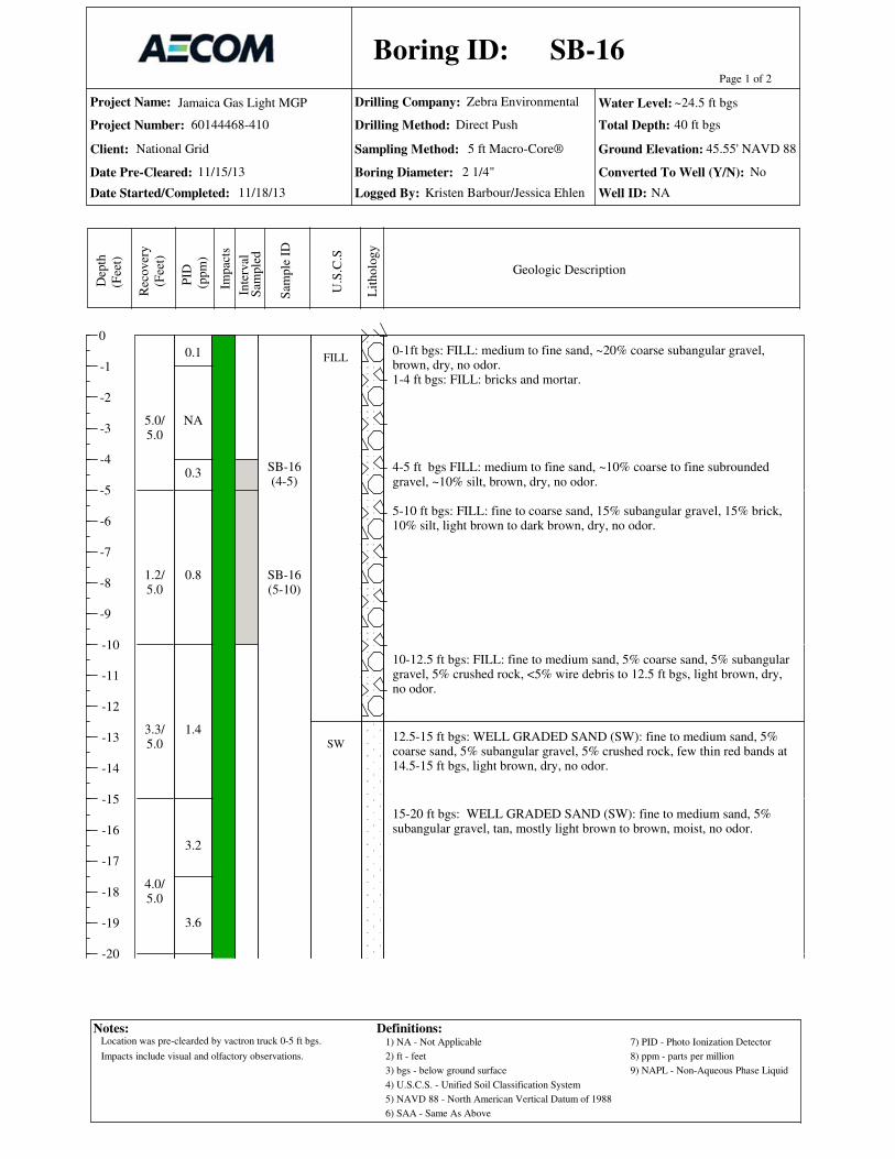
Project Name:
Project Number:
Date Pre-Cleared:
Date Started/Completed:
Drilling Company:
Drilling Method:
Sampling Method: Ground Elevation:
Total Depth:
Logged By:
0
-1
-2
-3
-4
-5
-6
-7
-8
-9
-10
-11
-12
-13
-14
-15
-16
-17
-18
-19
-20
Page 1 of 2
Dep
th
(Fee
t)
Rec
over
y
(Fee
t)
PID
(ppm
)
Sam
ple
ID
Inte
rval
Lit
holo
gy
U.S
.C.S
Geologic Description
Boring ID:
Jamaica Gas Light MGP
60144468-410
Zebra Environmental
Impac
ts
Water Level:
Client:
Boring Diameter: Converted To Well (Y/N):
Well ID:
National Grid 5 ft Macro-Core®
Notes: Definitions:1) NA - Not Applicable
2) ft - feet
3) bgs - below ground surface
4) U.S.C.S. - Unified Soil Classification System
5) NAVD 88 - North American Vertical Datum of 1988
6) SAA - Same As Above
7) PID - Photo Ionization Detector
8) ppm - parts per million
9) NAPL - Non-Aqueous Phase Liquid
No
NA
Direct Push
Sam
ple
d
0-1ft bgs: FILL: medium to fine sand, ~20% coarse subangular gravel,brown, dry, no odor.1-4 ft bgs: FILL: bricks and mortar.
4-5 ft bgs FILL: medium to fine sand, ~10% coarse to fine subroundedgravel, ~10% silt, brown, dry, no odor.
5-10 ft bgs: FILL: fine to coarse sand, 15% subangular gravel, 15% brick,10% silt, light brown to dark brown, dry, no odor.
10-12.5 ft bgs: FILL: fine to medium sand, 5% coarse sand, 5% subangulargravel, 5% crushed rock, <5% wire debris to 12.5 ft bgs, light brown, dry,no odor.
12.5-15 ft bgs: WELL GRADED SAND (SW): fine to medium sand, 5%coarse sand, 5% subangular gravel, 5% crushed rock, few thin red bands at14.5-15 ft bgs, light brown, dry, no odor.
15-20 ft bgs: WELL GRADED SAND (SW): fine to medium sand, 5%subangular gravel, tan, mostly light brown to brown, moist, no odor.
0.1
NA
0.3
0.8
1.4
3.2
3.6
5.0/5.0
1.2/5.0
3.3/5.0
4.0/5.0
SB-16(4-5)
SB-16(5-10)
FILL
SW
SB-16
11/18/13
45.55' NAVD 88
40 ft bgs
Kristen Barbour/Jessica Ehlen
11/15/13
~24.5 ft bgs
2 1/4"
Location was pre-clearded by vactron truck 0-5 ft bgs.
Impacts include visual and olfactory observations.

Project Name:
Project Number:
Date Pre-Cleared:
Date Started/Completed:
Drilling Company:
Drilling Method:
Sampling Method: Ground Elevation:
Total Depth:
Logged By:
-20
-21
-22
-23
-24
-25
-26
-27
-28
-29
-30
-31
-32
-33
-34
-35
-36
-37
-38
-39
-40
Page 2 of 2
Dep
th
(Fee
t)
Rec
over
y
(Fee
t)
PID
(ppm
)
Sam
ple
ID
Inte
rval
Lit
holo
gy
U.S
.C.S
Geologic Description
Boring ID:
Jamaica Gas Light MGP
60144468-410
Zebra Environmental
Impac
ts
Water Level:
Client:
Boring Diameter: Converted To Well (Y/N):
Well ID:
National Grid 5 ft Macro-Core®
Notes: Definitions:1) NA - Not Applicable
2) ft - feet
3) bgs - below ground surface
4) U.S.C.S. - Unified Soil Classification System
5) NAVD 88 - North American Vertical Datum of 1988
6) SAA - Same As Above
7) PID - Photo Ionization Detector
8) ppm - parts per million
9) NAPL - Non-Aqueous Phase Liquid
No
NA
Direct Push
Sam
ple
d
20-25 ft bgs: SAA: <5% coarse sand, wet at 24.5 ft bgs.
25-30 ft bgs: WELL GRADED SAND (SW): fine sand, 30% medium sand, <5% coarse sand, 5% subangular gravel, light brown, wet, no odor.
30-35 ft bgs: WELL GRADED SAND (SW): medium to fine sand, ~5%coarse sand, brown, wet, no odor.
35-40 ft bgs: WELL GRADED SAND (SW): coarse to fine sand, wet, lightbrown, no odor.
END OF BORING 40 ft bgs.
2.8
3.4
4.4
2.8
1.7
2.4
4.2/5.0
3.0/5.0
2.8/5.0
4.2/5.0 SB-16
(37.5-40)DUP
SB-16
11/18/13
45.55' NAVD 88
40 ft bgs
Kristen Barbour/Jessica Ehlen
11/15/13
~24.5 ft bgs
2 1/4"
Location was pre-clearded by vactron truck 0-5 ft bgs.
Impacts include visual and olfactory observations.

Project Name:
Project Number:
Date Pre-Cleared:
Date Started/Completed:
Drilling Company:
Drilling Method:
Sampling Method: Ground Elevation:
Total Depth:
Logged By:
0
-1
-2
-3
-4
-5
-6
-7
-8
-9
-10
-11
-12
-13
-14
-15
-16
-17
-18
-19
-20
Page 1 of 2
Dep
th
(Fee
t)
Rec
over
y
(Fee
t)
PID
(ppm
)
Sam
ple
ID
Inte
rval
Lit
holo
gy
U.S
.C.S
Geologic Description
Boring ID:
Jamaica Gas Light MGP
60144468-410
Zebra Environmental
Impac
ts
Water Level:
Client:
Boring Diameter: Converted To Well (Y/N):
Well ID:
National Grid 5 ft Macro-Core®
Notes: Definitions:1) NA - Not Applicable
2) ft - feet
3) bgs - below ground surface
4) U.S.C.S. - Unified Soil Classification System
5) NAVD 88 - North American Vertical Datum of 1988
6) SAA - Same As Above
7) PID - Photo Ionization Detector
8) ppm - parts per million
9) NAPL - Non-Aqueous Phase Liquid
No
NA
Direct Push
Sam
ple
d
0-0.08 ft bgs: ASPHALT0.08-1.5 ft bgs: FILL: medium to fine sand, ~20% coarse sand, ~20% silt,~10% coarse to fine subrounded gravel, <5% brick debris, brown, dry, noodor.1.5-5 ft bgs: FILL: medium to fine sand and silt, ~10% coarse to finesubrounded gravel, dry, brown, no odor.
5-10 ft bgs: FILL: silty fine to medium sand, 5% subrounded gravel, <5%brick debris, <5% asphalt debris, brown, dry, no odor.
10-15 ft bgs: SILTY SAND (SM): silt grading to fine sand, ~5% mediumsand, brown, dry, no odor.
15-20 ft bgs: WELL GRADED SAND (SW): fine to medium sand, ~5%coarse sand, 15% subangular gravel, light brown, moist, no odor.
0.2
0.2
2.6
3.4
3.2
5.0/5.0
2.5/5.0
2.5/5.0
4.0/5.0
SB-17(2-5)
SB-17(5-10)
SB-17(10-15)
MS/MSD
FILL
SM
SW
SB-17
11/18/13
45.72' NAVD 88
40 ft bgs
Jessica Ehlen/ Kristen Barbour
11/15/13
~25 ft bgs
2 1/4"
Location was pre-clearded by vactron truck 0-5 ft bgs.
Impacts include visual and olfactory observations.

Project Name:
Project Number:
Date Pre-Cleared:
Date Started/Completed:
Drilling Company:
Drilling Method:
Sampling Method: Ground Elevation:
Total Depth:
Logged By:
-20
-21
-22
-23
-24
-25
-26
-27
-28
-29
-30
-31
-32
-33
-34
-35
-36
-37
-38
-39
-40
Page 2 of 2
Dep
th
(Fee
t)
Rec
over
y
(Fee
t)
PID
(ppm
)
Sam
ple
ID
Inte
rval
Lit
holo
gy
U.S
.C.S
Geologic Description
Boring ID:
Jamaica Gas Light MGP
60144468-410
Zebra Environmental
Impac
ts
Water Level:
Client:
Boring Diameter: Converted To Well (Y/N):
Well ID:
National Grid 5 ft Macro-Core®
Notes: Definitions:1) NA - Not Applicable
2) ft - feet
3) bgs - below ground surface
4) U.S.C.S. - Unified Soil Classification System
5) NAVD 88 - North American Vertical Datum of 1988
6) SAA - Same As Above
7) PID - Photo Ionization Detector
8) ppm - parts per million
9) NAPL - Non-Aqueous Phase Liquid
No
NA
Direct Push
Sam
ple
d
20-25 ft bgs: WELL GRADED SAND (SW): medium to fine sand, ~10%coarse sand, brown to light brown, moist, no odor.
25-30 ft bgs: WELL GRADED SAND (SW): coarse to fine sand, brown,wet, no odor.
30-35 ft bgs: SAA.
35-40 ft bgs: SAA.
END OF BORING 40 ft bgs.
3.6
3.2
3.0
3.3
2.7
2.8
3.0
4.0/5.0
4.0/5.0
5.0/5.0
5.0/5.0
SB-17(37.5-40)
SB-17
11/18/13
45.72' NAVD 88
40 ft bgs
Jessica Ehlen/ Kristen Barbour
11/15/13
~25 ft bgs
2 1/4"
Location was pre-clearded by vactron truck 0-5 ft bgs.
Impacts include visual and olfactory observations.

Project Name:
Project Number:
Date Pre-Cleared:
Date Started/Completed:
Drilling Company:
Drilling Method:
Sampling Method: Ground Elevation:
Total Depth:
Logged By:
0
-1
-2
-3
-4
-5
-6
-7
-8
-9
-10
-11
-12
-13
-14
-15
-16
-17
-18
-19
-20
Page 1 of 2
Dep
th
(Fee
t)
Rec
over
y
(Fee
t)
PID
(ppm
)
Sam
ple
ID
Inte
rval
Lit
holo
gy
U.S
.C.S
Geologic Description
Boring ID:
Jamaica Gas Light MGP
60144468-410
Zebra Environmental
Impac
ts
Water Level:
Client:
Boring Diameter: Converted To Well (Y/N):
Well ID:
National Grid 5 ft Macro-Core®
Notes: Definitions:1) NA - Not Applicable
2) ft - feet
3) bgs - below ground surface
4) U.S.C.S. - Unified Soil Classification System
5) NAVD 88 - North American Vertical Datum of 1988
6) SAA - Same As Above
7) PID - Photo Ionization Detector
8) ppm - parts per million
9) NAPL - Non-Aqueous Phase Liquid
No
NA
Direct Push
Sam
ple
d
0-0.17 ft bgs: ASPHALT0.17-1 ft bgs: FILL: medium to fine sand, ~20% silt, ~5% brick debris,<5% rounded cobbles up to 6-inches in diameter, brown, dry, no odor.
1-5 ft bgs: WELL GRADED SAND (SW): medium to fine sand, ~20%coarse sand, ~20% coarse to fine subrounded gravel, brown, dry, no odor.
5-10 ft bgs: SAA, brown 5-6 ft bgs, orange brown 6-9 ft bgs, light brown 9-10 ft bg.
10-15 ft bgs: WELL GRADED SAND (SW): fine sand, ~20% coarse sand,~10% coarse to fine subrounded gravel, loose, dry, light brown, no odor.
15-20 ft bgs: WELL GRADED SAND (SW): fine sand, ~20% mediumsand, <5% coarse to fine subrounded gravel, light brown, moist, no odor.
0.1
0.8
1.9
0.9
1.2
5.0/5.0
2.5/5.0
3.0/5.0
4.0/5.0
SB-18(2-5)
SB-18(15-17.5)
FILL
SW
SB-18
11/19/13
43.36' NAVD 88
40 ft bgs
Jessica Ehlen
11/15/13
~23 ft bgs
2 1/4"
Location was pre-clearded by vactron truck 0-5 ft bgs.
Impacts include visual and olfactory observations.

Project Name:
Project Number:
Date Pre-Cleared:
Date Started/Completed:
Drilling Company:
Drilling Method:
Sampling Method: Ground Elevation:
Total Depth:
Logged By:
-20
-21
-22
-23
-24
-25
-26
-27
-28
-29
-30
-31
-32
-33
-34
-35
-36
-37
-38
-39
-40
Page 2 of 2
Dep
th
(Fee
t)
Rec
over
y
(Fee
t)
PID
(ppm
)
Sam
ple
ID
Inte
rval
Lit
holo
gy
U.S
.C.S
Geologic Description
Boring ID:
Jamaica Gas Light MGP
60144468-410
Zebra Environmental
Impac
ts
Water Level:
Client:
Boring Diameter: Converted To Well (Y/N):
Well ID:
National Grid 5 ft Macro-Core®
Notes: Definitions:1) NA - Not Applicable
2) ft - feet
3) bgs - below ground surface
4) U.S.C.S. - Unified Soil Classification System
5) NAVD 88 - North American Vertical Datum of 1988
6) SAA - Same As Above
7) PID - Photo Ionization Detector
8) ppm - parts per million
9) NAPL - Non-Aqueous Phase Liquid
No
NA
Direct Push
Sam
ple
d
20-22.5 ft bgs: WELL GRADED SAND (SW): medium to fine sand, ~10% coarse sand, ~10% coarse to fine subrounded gravel, moist, light brown, no odor, few bands of orange-brown sand throughout.
22.5-25 ft bgs: WELL GRADED SAND (SW): coarse to fine sand, ~10%coarse to fine subrounded gravel, moist 22.5-23 ft bgs, wet 23-25 ft bgs, noodor, few bands of orange brown and brown sand throughout.
25-27 ft bgs POORLY GRADED SAND (SP): fine sand, ~10% mediumsand, light brown, wet, no odor.
27-30 ft bgs: WELL GRADED SAND (SW): coarse to fine sand, ~15%coarse to fine subrounded gravel, brown, wet, no odor.
30-35 ft bgs: SAA.
35-40 ft bgs: WELL GRADED SAND (SW): coarse to fine sand, brown,wet, no odor.
END OF BORING 40 ft bgs.
0.9
1.0
1.4
1.4
0.9
1.1
1.1
4.5/5.0
5.0/5.0
5.0/5.0
5.0/5.0
SB-18(37.5-40)
SP
SW
SB-18
11/19/13
43.36' NAVD 88
40 ft bgs
Jessica Ehlen
11/15/13
~23 ft bgs
2 1/4"
Location was pre-clearded by vactron truck 0-5 ft bgs.
Impacts include visual and olfactory observations.

Project Name:
Project Number:
Date Pre-Cleared:
Date Started/Completed:
Drilling Company:
Drilling Method:
Sampling Method: Ground Elevation:
Total Depth:
Logged By:
0
-1
-2
-3
-4
-5
-6
-7
-8
-9
-10
-11
-12
-13
-14
-15
-16
-17
-18
-19
-20
Page 1 of 2
Dep
th
(Fee
t)
Rec
over
y
(Fee
t)
PID
(ppm
)
Sam
ple
ID
Inte
rval
Lit
holo
gy
U.S
.C.S
Geologic Description
Boring ID:
Jamaica Gas Light MGP
60144468-410
Zebra Environmental
Impac
ts
Water Level:
Client:
Boring Diameter: Converted To Well (Y/N):
Well ID:
National Grid 5 ft Macro-Core®
Notes: Definitions:1) NA - Not Applicable
2) ft - feet
3) bgs - below ground surface
4) U.S.C.S. - Unified Soil Classification System
5) NAVD 88 - North American Vertical Datum of 1988
6) SAA - Same As Above
7) PID - Photo Ionization Detector
8) ppm - parts per million
9) NAPL - Non-Aqueous Phase Liquid
No
NA
Direct Push
Sam
ple
d
0-0.17 ft bgs: ASPHALT0.17-3 ft bgs: FILL: medium to fine sand, 10% silt, ~10% coarse to finerounded to subrounded gravel, <5% brick debris, <5% plant roots, brown,dry, no odor.
3-6 ft bgs: WELL GRADED SAND (SW): medium to fine sand, 10% silt,~10% coarse to fine rounded to subrounded gravel, <5% plant roots, brown, dry, no odor.
6-10 ft bgs: WELL GRADED SAND (SW): medium to fine sand, ~20%coarse sand, ~15% coarse to subrounded gravel, ~5% silt, dry, brown 6 -8 ft bgs, light brown 8-10 ft bgs, no odor.
10-15 ft bgs: WELL GRADED SAND (SW): medium to fine sand, ~15%coarse sand, ~10% coarse to fine subangular to subrounded gravel, dry,light brown, no odor.
15-17.5 ft bgs: SILTY SAND (SM): medium to fine sand, ~25% silt, ~5%coarse to fine subrounded gravel, brown, dry, no odor.
17.5-20 ft bgs: WELL GRADED SAND (SW): medium to fine sand, ~20% coarse sand, ~5% coarse to fine subrounded gravel, light brown, moist, noodor.
0.3
0.2
0.0
0.0
0.2
0.0
6.0/6.0
4.0/4.0
3.5/5.0
5.0/5.0
SB-19(2-5)
MS/MSD
SB-19(10-15)
FILL
SW
SM
SW
SB-19
11/12/13
47.17' NAVD 88
40 ft bgs
Jessica Ehlen
11/12/13
~30 ft bgs
2 1/4"
Location was pre-clearded by vactron truck 0-5 ft bgs.
Impacts include visual and olfactory observations.

Project Name:
Project Number:
Date Pre-Cleared:
Date Started/Completed:
Drilling Company:
Drilling Method:
Sampling Method: Ground Elevation:
Total Depth:
Logged By:
-20
-21
-22
-23
-24
-25
-26
-27
-28
-29
-30
-31
-32
-33
-34
-35
-36
-37
-38
-39
-40
Page 2 of 2
Dep
th
(Fee
t)
Rec
over
y
(Fee
t)
PID
(ppm
)
Sam
ple
ID
Inte
rval
Lit
holo
gy
U.S
.C.S
Geologic Description
Boring ID:
Jamaica Gas Light MGP
60144468-410
Zebra Environmental
Impac
ts
Water Level:
Client:
Boring Diameter: Converted To Well (Y/N):
Well ID:
National Grid 5 ft Macro-Core®
Notes: Definitions:1) NA - Not Applicable
2) ft - feet
3) bgs - below ground surface
4) U.S.C.S. - Unified Soil Classification System
5) NAVD 88 - North American Vertical Datum of 1988
6) SAA - Same As Above
7) PID - Photo Ionization Detector
8) ppm - parts per million
9) NAPL - Non-Aqueous Phase Liquid
No
NA
Direct Push
Sam
ple
d
20-25 ft bgs: WELL GRADED SAND (SW): coarse to fine sand, ~10%coarse to fine subrounded gravel, light brown, few reddish-orange bandsthroughout, moist, no odor.
25-30 ft bgs: WELL GRADED SAND (SW): coarse to fine sand, 10%coarse to fine subrounded gravel, light brown with few dark brown bandsthroughtout, moist, no odor.
30-32 ft bgs: SAA: brown.
32-35 ft bgs: WELL GRADED SAND (SW): medium to fine sand, ~10%coarse sand, brown, wet, no odor.
35-40 ft bgs: SAA: 2- inch thick layer of fine subrounded gravel from 39'6''to 39'8''.
END OF BORING 40 ft bgs.
0.0
0.1
0.0
0.0
0.1
0.0
3.5/5.0
4.0/5.0
4.2/5.0
5.0/5.0
SB-19(37.5-40)
SB-19
11/12/13
47.17' NAVD 88
40 ft bgs
Jessica Ehlen
11/12/13
~30 ft bgs
2 1/4"
Location was pre-clearded by vactron truck 0-5 ft bgs.
Impacts include visual and olfactory observations.

Project Name:
Project Number:
Date Pre-Cleared:
Date Started/Completed:
Drilling Company:
Drilling Method:
Sampling Method: Ground Elevation:
Total Depth:
Logged By:
0
-1
-2
-3
-4
-5
-6
-7
-8
-9
-10
-11
-12
-13
-14
-15
-16
-17
-18
-19
-20
Page 1 of 2D
epth
(ft
)
Rec
over
y (
ft)
PID
(ppm
)
Sam
ple
ID
Inte
rval
Lit
holo
gy
U.S
.C.S
Geologic Description
Boring ID:
Notes:
Jamaica Gas Light MGP
60144468-410
Zebra Environmental
Impac
ts
Water Level:
Client:
Boring Diameter: Converted To Well (Y/N):
Well ID:
Wel
l
Definitions:
Sam
ple
d
1) NA - Not Applicable
2) ft - feet
3) bgs - below ground surface
4) U.S.C.S.- Unified Soil Classification System
8) ppm - parts per million
6) SAA - Same As Above
7) PID - Photo Ionization Detector
5) NAVD 88 - North American Vertical Datum of 1988
9) NAPL - Non-Aqueous Phase Liquid
5 ft Macro-Core®
Const
ruct
ion
National Grid
Direct Push / HSA
10) HSA - Hollow Stem Auger
0-0.17 ft bgs: ASPHALT0.17-1 ft bgs: FILL: medium to fine sand and silt, ~5% brick debris, ~5%coarse to fine subrounded gravel, moist, brown, no odor, <5% tree rootsthroughtout.1-2 ft bgs: SAA, pipe debris at 1.5 ft bgs, no odor.2-3 ft bgs: SAA, no brick debris.3-5 ft bgs: FILL: medium to fine sand and silt, ~5% coarse to fine subrounded gravel, moist, brown, no odor.
5-6 ft bgs: SAA.6-10 ft bgs: FILL: medium to fine sand, ~10% coarse to fine subroundedgravel, dry, light brown, no odor, 2-inch band of dark brown sand from 9.17-9.33 ft bgs
10-15 ft bgs: FILL: medium to fine sand, ~5% coarse to fine subroundedgravel, <5% slag, brown, few bands of dark brown to black stainingthroughout, dry, slight tar-like odor.
15-17.5 ft bgs: SAA, few bands of black staining, no odor.
17.5-20 ft bgs: WELL GRADED SAND (SW): medium to fine sand, ~10%coarse sand, ~5% coarse to fine subangular gravel, moist, light brown, noodor.
0.9
2.4
1.2
3.8
26.4
1.4
10.7
5.0/5.0
3.0/5.0
2.8/5.0
3.4/5.0
SB-20(2-5)DUP
SB-20(12.5-15)
SB-20(17.5-20)
FILL
SW
SB-20/MW-7
11/13/13
46.06' NAVD 88
40 ft bgs
Jessica Ehlen
11/12/13
~27.5 ft bgs
2 1/4" YES
MW-7
Location was pre-cleared by vactron truck from 0-5 ft bgs
A 2" well was installed from 24-34 ft bgs.
Impacts include visual and olfactory.
Flush mount road box with concrete pad installed at this location.

Project Name:
Project Number:
Date Pre-Cleared:
Date Started/Completed:
Drilling Company:
Drilling Method:
Sampling Method: Ground Elevation:
Total Depth:
Logged By:
-20
-21
-22
-23
-24
-25
-26
-27
-28
-29
-30
-31
-32
-33
-34
-35
-36
-37
-38
-39
-40
Page 2 of 2D
epth
(ft
)
Rec
over
y (
ft)
PID
(ppm
)
Sam
ple
ID
Inte
rval
Lit
holo
gy
U.S
.C.S
Geologic Description
Boring ID:
Notes:
Jamaica Gas Light MGP
60144468-410
Zebra Environmental
Impac
ts
Water Level:
Client:
Boring Diameter: Converted To Well (Y/N):
Well ID:
Wel
l
Definitions:
Sam
ple
d
1) NA - Not Applicable
2) ft - feet
3) bgs - below ground surface
4) U.S.C.S.- Unified Soil Classification System
8) ppm - parts per million
6) SAA - Same As Above
7) PID - Photo Ionization Detector
5) NAVD 88 - North American Vertical Datum of 1988
9) NAPL - Non-Aqueous Phase Liquid
5 ft Macro-Core®
Const
ruct
ion
National Grid
Direct Push / HSA
10) HSA - Hollow Stem Auger
20-25 ft bgs: WELL GRADED SAND (SW): medium to fine sand, 5% coarse sand, light brown, moist, no odor, reddish orange from 23-24 ft bgs.
25-27.5 ft bgs: WELL GRADED SAND (SW): fine sand, ~20% mediumsand, <5% fine subrounded gravel, light brown, wet, no odor.
27.5-30 ft bgs: WELL GRADED SAND (SW): medium to fine sand, ~10%coarse sand, ~10% coarse to fine subrounded gravel, light brown, wet, noodor.
30-35 ft bgs: WELL GRADED SAND (SW): coarse to fine sand, <5% coarse to fine subrounded gravel, brown, wet, no odor.
35-40 ft bgs: WELL GRADED SAND (SW): medium to fine sand, ~25%coarse sand, wet, brown, no odor.
END OF BORING 40 ft bgs.
16.8
13.2
4.5
2.0
2.0
1.8
0.7
4.6/5.0
5.0/5.0
4.5/5.0
4.0/5.0
SB-20/MW-7
11/13/13
46.06' NAVD 88
40 ft bgs
Jessica Ehlen
11/12/13
~27.5 ft bgs
2 1/4" YES
MW-7
Location was pre-cleared by vactron truck from 0-5 ft bgs
A 2" well was installed from 24-34 ft bgs.
Impacts include visual and olfactory.
Flush mount road box with concrete pad installed at this location.

Project Name:
Project Number:
Date Pre-Cleared:
Date Started/Completed:
Drilling Company:
Drilling Method:
Sampling Method: Ground Elevation:
Total Depth:
Logged By:
0
-1
-2
-3
-4
-5
-6
-7
-8
-9
-10
-11
-12
-13
-14
-15
-16
-17
-18
-19
-20
Page 1 of 2D
epth
(ft
)
Rec
over
y (
ft)
PID
(ppm
)
Sam
ple
ID
Inte
rval
Lit
holo
gy
U.S
.C.S
Geologic Description
Boring ID:
Notes:
Jamaica Gas Light MGP
60144468-410
Zebra Environmental
Impac
ts
Water Level:
Client:
Boring Diameter: Converted To Well (Y/N):
Well ID:
Wel
l
Definitions:
Sam
ple
d
1) NA - Not Applicable
2) ft - feet
3) bgs - below ground surface
4) U.S.C.S.- Unified Soil Classification System
8) ppm - parts per million
6) SAA - Same As Above
7) PID - Photo Ionization Detector
5) NAVD 88 - North American Vertical Datum of 1988
9) NAPL - Non-Aqueous Phase Liquid
5 ft Macro-Core®
Const
ruct
ion
National Grid
Direct Push / HSA
10) HSA - Hollow Stem Auger
0-0.33 ft bgs: ASPHALT0.33-1.5 ft bgs: FILL: medium to fine sand, ~10% silt, ~5% concrete andbrick debris, 5% coarse rounded gravel, moist, no odor.1.5-3 ft bgs: SAA: moist, no odor.
3-5 ft bgs SAA.
5-10 ft bgs: FILL: medium to fine sand, ~10% coarse sand, ~10% silt, ~5%brick debris, brown, dry, no odor.
10-15 ft bgs: WELL GRADED SAND (SW): medium to fine sand, ~10%coarse sand, ~5% subrounded gravel, moist, no odor.
15-20 ft bgs: POORLY GRADED SAND (SP): fine sand, ~10% mediumsand, <5% subrounded gravel, moist, light brown, no odor.
0.1
0.3
0.4
NA
5.0/5.0
2.6/5.0
1.9/5.0
3.6/5.0
SB-21(1-5)
SB-21(5-10)
SB-21(10-15)
FILL
SW
SP
SB-21/MW-8
11/10/13
45.14' NAVD88
40 ft bgs
Jessica Ehlen
11/9/13
~28 ft bgs
2 1/4" YES
MW-8
Location was pre-cleared by vactron truck from 0-5 ft bgs.
A 2" well was installed from 26-36 ft bgs.
Impacts include visual and olfactory observations.
Flush mount road box with concrete pad installed at this location.

Project Name:
Project Number:
Date Pre-Cleared:
Date Started/Completed:
Drilling Company:
Drilling Method:
Sampling Method: Ground Elevation:
Total Depth:
Logged By:
-20
-21
-22
-23
-24
-25
-26
-27
-28
-29
-30
-31
-32
-33
-34
-35
-36
-37
-38
-39
-40
Page 2 of 2D
epth
(ft
)
Rec
over
y (
ft)
PID
(ppm
)
Sam
ple
ID
Inte
rval
Lit
holo
gy
U.S
.C.S
Geologic Description
Boring ID:
Notes:
Jamaica Gas Light MGP
60144468-410
Zebra Environmental
Impac
ts
Water Level:
Client:
Boring Diameter: Converted To Well (Y/N):
Well ID:
Wel
l
Definitions:
Sam
ple
d
1) NA - Not Applicable
2) ft - feet
3) bgs - below ground surface
4) U.S.C.S.- Unified Soil Classification System
8) ppm - parts per million
6) SAA - Same As Above
7) PID - Photo Ionization Detector
5) NAVD 88 - North American Vertical Datum of 1988
9) NAPL - Non-Aqueous Phase Liquid
5 ft Macro-Core®
Const
ruct
ion
National Grid
Direct Push / HSA
10) HSA - Hollow Stem Auger
20-25 ft bgs: POORLY GRADED SAND (SP): fine sand, <5% coarse sand,light brown, dark brown 21-22 ft bgs, moist, no odor.
25-28 ft bgs: SAA.
28-30 ft bgs: WELL GRADED SAND (SW): fine sand, ~20% medium tocoarse sand, ~10% fine subrounded gravel, brown, wet, no odor.
30-35 ft bgs: WELL GRADED SAND (SW): coarse to fine sand, brown, wet, no odor.
35-40 ft bgs: SAA: no odor.
END OF BORING 40 ft bgs.
0.5
0.5
0.6
0.1
4.5/5.0
5.0/5.0
5.0/5.0
2.3/5.0
SB-21(35-40)
SW
SB-21/MW-8
11/10/13
45.14' NAVD88
40 ft bgs
Jessica Ehlen
11/9/13
~28 ft bgs
2 1/4" YES
MW-8
Location was pre-cleared by vactron truck from 0-5 ft bgs.
A 2" well was installed from 26-36 ft bgs.
Impacts include visual and olfactory observations.
Flush mount road box with concrete pad installed at this location.
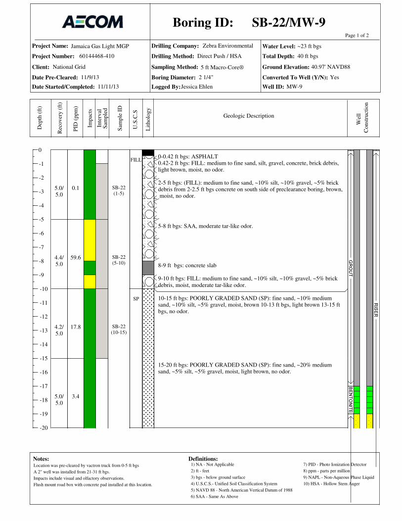
Project Name:
Project Number:
Date Pre-Cleared:
Date Started/Completed:
Drilling Company:
Drilling Method:
Sampling Method: Ground Elevation:
Total Depth:
Logged By:
0
-1
-2
-3
-4
-5
-6
-7
-8
-9
-10
-11
-12
-13
-14
-15
-16
-17
-18
-19
-20
Page 1 of 2D
epth
(ft
)
Rec
over
y (
ft)
PID
(ppm
)
Sam
ple
ID
Inte
rval
Lit
holo
gy
U.S
.C.S
Geologic Description
Boring ID:
Notes:
Jamaica Gas Light MGP
60144468-410
Zebra Environmental
Impac
ts
Water Level:
Client:
Boring Diameter: Converted To Well (Y/N):
Well ID:
Wel
l
Definitions:
Sam
ple
d
1) NA - Not Applicable
2) ft - feet
3) bgs - below ground surface
4) U.S.C.S.- Unified Soil Classification System
8) ppm - parts per million
6) SAA - Same As Above
7) PID - Photo Ionization Detector
5) NAVD 88 - North American Vertical Datum of 1988
9) NAPL - Non-Aqueous Phase Liquid
5 ft Macro-Core®
Const
ruct
ion
National Grid
Direct Push / HSA
10) HSA - Hollow Stem Auger
0-0.42 ft bgs: ASPHALT0.42-2 ft bgs: FILL: medium to fine sand, silt, gravel, concrete, brick debris,light brown, moist, no odor.
2-5 ft bgs: (FILL): medium to fine sand, ~10% silt, ~10% gravel, ~5% brickdebris from 2-2.5 ft bgs concrete on south side of preclearance boring, brown, moist, no odor.
5-8 ft bgs: SAA, moderate tar-like odor.
8-9 ft bgs: concrete slab
9-10 ft bgs: FILL: medium to fine sand, ~10% silt, ~10% gravel, ~5% brickdebris, moist, moderate tar-like odor.
10-15 ft bgs: POORLY GRADED SAND (SP): fine sand, ~10% mediumsand, ~10% silt, ~5% gravel, moist, brown 10-13 ft bgs, light brown 13-15 ftbgs, no odor.
15-20 ft bgs: POORLY GRADED SAND (SP): fine sand, ~20% mediumsand, ~5% silt, ~5% gravel, moist, light brown, no odor.
0.1
59.6
17.8
3.4
5.0/5.0
4.4/5.0
4.2/5.0
5.0/5.0
SB-22(1-5)
SB-22(5-10)
SB-22(10-15)
FILL
SP
SB-22/MW-9
11/11/13
40.97' NAVD88
40 ft bgs
Jessica Ehlen
11/9/13
~23 ft bgs
2 1/4" Yes
MW-9
Location was pre-cleared by vactron truck from 0-5 ft bgs
A 2" well was installed from 21-31 ft bgs.
Impacts include visual and olfactory observations.
Flush mount road box with concrete pad installed at this location.

Project Name:
Project Number:
Date Pre-Cleared:
Date Started/Completed:
Drilling Company:
Drilling Method:
Sampling Method: Ground Elevation:
Total Depth:
Logged By:
-20
-21
-22
-23
-24
-25
-26
-27
-28
-29
-30
-31
-32
-33
-34
-35
-36
-37
-38
-39
-40
Page 2 of 2D
epth
(ft
)
Rec
over
y (
ft)
PID
(ppm
)
Sam
ple
ID
Inte
rval
Lit
holo
gy
U.S
.C.S
Geologic Description
Boring ID:
Notes:
Jamaica Gas Light MGP
60144468-410
Zebra Environmental
Impac
ts
Water Level:
Client:
Boring Diameter: Converted To Well (Y/N):
Well ID:
Wel
l
Definitions:
Sam
ple
d
1) NA - Not Applicable
2) ft - feet
3) bgs - below ground surface
4) U.S.C.S.- Unified Soil Classification System
8) ppm - parts per million
6) SAA - Same As Above
7) PID - Photo Ionization Detector
5) NAVD 88 - North American Vertical Datum of 1988
9) NAPL - Non-Aqueous Phase Liquid
5 ft Macro-Core®
Const
ruct
ion
National Grid
Direct Push / HSA
10) HSA - Hollow Stem Auger
20-25 ft bgs: WELL GRADED SAND (SW): fine sand, ~25% medium tocoarse sand, ~10% coarse to fine subangular gravel, light brown, no odor,moist 20-23 ft bgs, wet 23-25 ft bgs.
25-30 ft bgs: WELL GRADED SAND (SW): fine to coarse sand, <5% gravel, wet, brown, no odor.
30-35 ft bgs: WELL GRADED SAND (SW): coarse to fine sand, 5% finesubangular gravel, wet, brown, no odor.
35-40 ft bgs: WELL GRADED SAND (SW): medium to fine sand, ~25%coarse sand, ~5% fine subangular gravel, wet, brown, no odor.
END OF BORING 40 ft bgs.
4.7
0.5
0.0
0.5
3.5/5.0
4.6/5.0
5.0/5.0
5.0/5.0
SB-22(35-40)
SW
SB-22/MW-9
11/11/13
40.97' NAVD88
40 ft bgs
Jessica Ehlen
11/9/13
~23 ft bgs
2 1/4" Yes
MW-9
Location was pre-cleared by vactron truck from 0-5 ft bgs
A 2" well was installed from 21-31 ft bgs.
Impacts include visual and olfactory observations.
Flush mount road box with concrete pad installed at this location.

Project Name:
Project Number:
Date Pre-Cleared:
Date Started/Completed:
Drilling Company:
Drilling Method:
Sampling Method: Ground Elevation:
Total Depth:
Logged By:
0
-1
-2
-3
-4
-5
-6
-7
-8
-9
-10
-11
-12
-13
-14
-15
-16
-17
-18
-19
-20
Page 1 of 2D
epth
(ft
)
Rec
over
y (
ft)
PID
(ppm
)
Sam
ple
ID
Inte
rval
Lit
holo
gy
U.S
.C.S
Geologic Description
Boring ID:
Notes:
Jamaica Gas Light MGP
60144468-410
Zebra Environmental
Impac
ts
Water Level:
Client:
Boring Diameter: Converted To Well (Y/N):
Well ID:
Wel
l
Definitions:
Sam
ple
d
1) NA - Not Applicable
2) ft - feet
3) bgs - below ground surface
4) U.S.C.S.- Unified Soil Classification System
8) ppm - parts per million
6) SAA - Same As Above
7) PID - Photo Ionization Detector
5) NAVD 88 - North American Vertical Datum of 1988
9) NAPL - Non-Aqueous Phase Liquid
5 ft Macro-Core®
Const
ruct
ion
National Grid
Direct Push / HSA
10) HSA - Hollow Stem Auger
0-0.08 ft bgs: Grass0.08-2 ft bgs: FILL: fine sand, ~25% medium sand, ~10% silt, ~5% coarserounded gravel, ~5% brick debris, dry, brown, no odor.2-4 ft bgs: SAA, ~10% cobbles up to 6-inches in diameter.
4-5 ft bgs: FILL: bricks, scattered throughout.
5-9 ft bgs: FILL: concrete and brick debris, <5% medium to fine sand, dry, no odor.
9-10 ft bgs:(FILL): medium to fine sand and silt, ~20% coarse sand, ~10%coarse subrounded gravel, dry, brown, no odor.
10-15 ft bgs: FILL: medium to fine sand, ~20% coarse sand, ~15% coarsesubrounded gravel, dry, brown, no odor.
15-17.5 ft bgs: FILL: fine sand, ~25% silt, ~20% coarse to fine subroundedgravel, <5% brick debris, moist, no odor.
17.5-20 ft bgs: WELL GRADED SAND (SW): medium to fine sand, ~20%coarse sand, ~10% coarse to fine subrounded gravel, brown, moist 17.5-19 ftbgs, wet 19-20 ft bgs, no odor.
0.1
NA
0.3
0.4
0.4
0.7
0.5
5.0/5.0
2.3/5.0
4.0/5.0
5.0/5.0
SB-23(1-4)
SB-23(5-10)
FILL
SW
SB-23/MW-10
11/16/13
37.77' NAVD88
40 ft bgs
Jessica Ehlen
11/9/13
~19 ft bgs
2 1/4" Yes
MW-10
Location was pre-cleared by vactron truck from 0-5 ft bgs
A 2" well was istalled from 17-27 ft bgs
Impacts include visual and olfactory observations.
Flush mount road box with concrete pad installed at this location.

Project Name:
Project Number:
Date Pre-Cleared:
Date Started/Completed:
Drilling Company:
Drilling Method:
Sampling Method: Ground Elevation:
Total Depth:
Logged By:
-20
-21
-22
-23
-24
-25
-26
-27
-28
-29
-30
-31
-32
-33
-34
-35
-36
-37
-38
-39
-40
Page 2 of 2D
epth
(ft
)
Rec
over
y (
ft)
PID
(ppm
)
Sam
ple
ID
Inte
rval
Lit
holo
gy
U.S
.C.S
Geologic Description
Boring ID:
Notes:
Jamaica Gas Light MGP
60144468-410
Zebra Environmental
Impac
ts
Water Level:
Client:
Boring Diameter: Converted To Well (Y/N):
Well ID:
Wel
l
Definitions:
Sam
ple
d
1) NA - Not Applicable
2) ft - feet
3) bgs - below ground surface
4) U.S.C.S.- Unified Soil Classification System
8) ppm - parts per million
6) SAA - Same As Above
7) PID - Photo Ionization Detector
5) NAVD 88 - North American Vertical Datum of 1988
9) NAPL - Non-Aqueous Phase Liquid
5 ft Macro-Core®
Const
ruct
ion
National Grid
Direct Push / HSA
10) HSA - Hollow Stem Auger
20-25 ft bgs: WELL GRADED SAND (SW): coarse to fine sand, ~25%coarse subrounded gravel, wet, brown, no odor.
25-30 ft bgs: WELL GRADED SAND (SW): medium to fine sand, ~15%coarse sand, ~5% coarse to fine subrounded gravel, brown, wet, no odor.
30-35 ft bgs: SAA.
35-40 ft bgs: WELL GRADED SAND (SW): coarse to fine sand, ~10%coarse to fine subrounded gravel, brown, wet, no odor.
END OF BORING 40 ft bgs.
0.6
0.8
0.6
0.9
0.9
0.8
0.9
2.0/5.0
4.2/5.0
4.0/5.0
5.0/5.0
SB-23(37.5-40)
SB-23/MW-10
11/16/13
37.77' NAVD88
40 ft bgs
Jessica Ehlen
11/9/13
~19 ft bgs
2 1/4" Yes
MW-10
Location was pre-cleared by vactron truck from 0-5 ft bgs
A 2" well was istalled from 17-27 ft bgs
Impacts include visual and olfactory observations.
Flush mount road box with concrete pad installed at this location.

TP-1
PROJECT NO: SURFACE ELEVATION: 44.74' NAVD88
CLIENT: START DATE: 11/6/13
SITE NAME: FINISH DATE: 11/7/13
GEOLOGIST: START TIME: 8:47 AM
DEPTH WATER ENCOUNTERED: NA FINISH TIME: 12:45 PM
DEPTH VISUAL PID SOIL SOIL SOIL
IMPACTS HEADSPACE STRATIG- CLASS DESCRIPTION STRUCTURES ENCOUNTERED
(FEET) (FEET) (PPM) RAPHY USCS USCS LOG OR COMMENTS
0-0.2 ft bgs: ASPHALT - 30% debris consisting of stone and brick from 0 to 3 ft bgs.
0.2-1 ft bgs: FILL: fine to medium sand, large subangular gravel, 20% bricks and concrete debris, brown, dry, no odor.
- Fill consisting of sand, and wood chip mixture. No odors. Concrete boulders 18-inches to 2-feet long and 4-inches thick.
1
2
2-3 ft bgs: FILL: SAA, concrete slab.
- Concrete foundation 4-inches thick approximately 6.5 ft south of north wall across entire test pit. Base of a pole present in slab.
- Two foot wide foundation extending from east to west across test pit. It is 1 ft south of north wall.
33-4 ft bgs: FILL: SAA, miscellaneous pipes, steel reinforcement debris. - Old sewer line 3 ft bgs south of north wall.
- Concrete foundation 6-inches thick, located 15 ft from north wall to 4.5 ft south of north wall. A lot of rebar observed.
4
4-5 ft bgs: FILL: fine to medium sand becoming lighter in color from brown to light brown, metal grate.
- Another 6-inch foundation present at 4 ft bgs across entire test pit.
- Multiple concrete foundations 6-inches thick down to 5 ft bgs.
- At 4 ft bgs, 3-inch pipe running north to south, no odor, gray.
5
5-6 ft bgs: FILL: fine to medium sand, some silt, tree roots, brown, dry, no odor. - Three inch waste pipe. running north to south. South end of pipe is 4 ft from the edge of 3 ft brick foundation, foundation curved at north end. Three grates at 5 ft bgs. - No significant debris present past 5 ft bgs.
- Three foot thick holder wall observed at 5 ft bgs. Holder present to bottom of excavation. Holder wall approximately 4 ft north of south wall aligned east to west.
- Soil south of the brick wall is dark brown clean sand with some silt.
6 - Soil north of the brick wall is light gray sand with wood chips mixed in.
6-7 ft bgs: FILL: fine to medium sand, 30% silt, ash ,wood, trace clinker, brown to light brown, dry.
77-8 ft bgs: FILL: SAA, NAPL odor.
88-9 ft bgs: FILL: SAA.
99-10 ft bgs: FILL: SAA.
1010-11 ft bgs: FILL: SAA, strong NAPL odor.
- Down to 14ft bgs, heavy odors detected.
1111-12 ft bgs: FILL: SAA, coated with NAPL, Strong NAPL odor.
12
12-13 ft bgs: FILL: SAA. - Perched Water present from 12 to 15 ft bgs, sheen on water surface.
1313-14 ft bgs: FILL: SAA, holder bottom encountered at 14 ft bgs.
- Bucket of excavator scrapped the bottom of the excavation. The soil at the bottom is coated with DNAPL.
14 END OF TEST PIT AT 14FT BGSDefinitions: 1.) NA - Not Applicable 4.) bgs - below ground surface 7.) NAVD 88 - North American Vertical Datum of 1988 10.) NAPL - nonaqueous phase liquid
2.) ft - feet 5.) ppm - parts per million 8.) U.S.C.S. - Unified Soil Classification System
3.) SAA - Same As Above 6.) PID - Photo Ionization Meter 9.) DNAPL - dense nonaqueous phase liquid
NA
Test Pit Log
NA
NA
1-2 ft bgs: FILL: fine to medium sand, 20% ash and wood, 10% brick and concrete, dark brown, dry, no odor.
Former Jamaica Gas Light MGP Site
National Grid
60144468
TOTAL DEPTH: 14 ft bgs
OPERATOR: Zebra
EQUIPMENT USED: Backhoe
SITE LOCATION OR AREA: Parking Lot currently rented by Royal Carting
Test Pit Designation: TP-1
NA
NA
NA
NA
S. Pandya, K. Barbour
NA
NA
NA
NA
NA
NA
NA
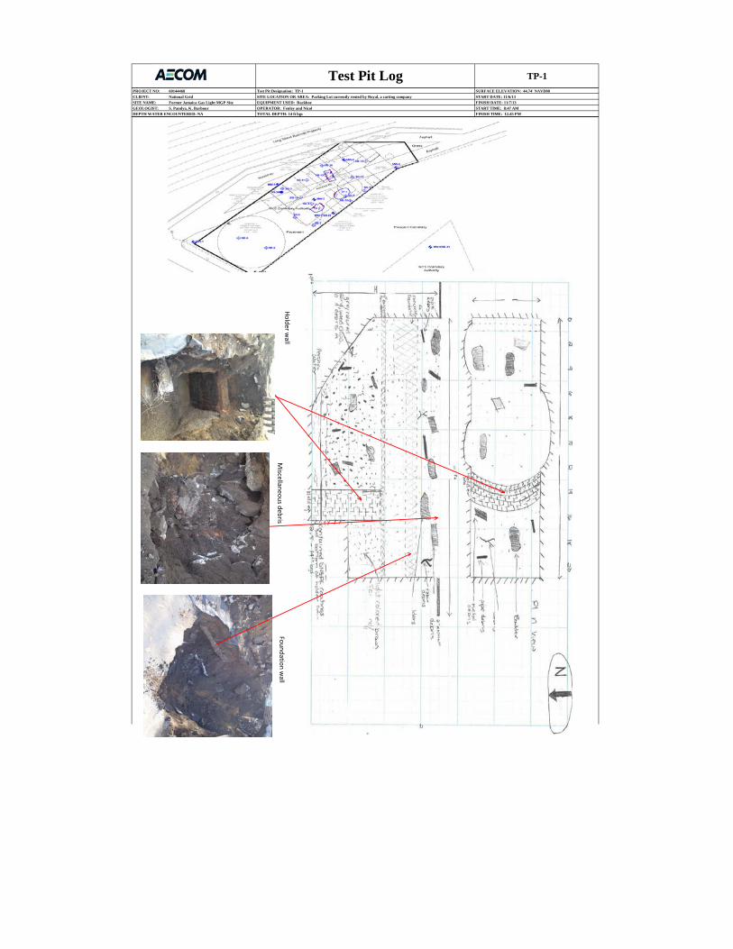
TP-1
PROJECT NO: SURFACE ELEVATION: 44.74' NAVD88
CLIENT: START DATE: 11/6/13
SITE NAME: FINISH DATE: 11/7/13
GEOLOGIST: START TIME: 8:47 AM
DEPTH WATER ENCOUNTERED: NA FINISH TIME: 12:45 PM
Test Pit Log60144468 Test Pit Designation: TP-1
National Grid SITE LOCATION OR AREA: Parking Lot currently rented by Royal, a carting company
Former Jamaica Gas Light MGP Site EQUIPMENT USED: Backhoe
S. Pandya, K. Barbour OPERATOR: Fenley and Nicol
TOTAL DEPTH: 14 ft bgs
Foundation wall
Miscellaneous debris
Holder wall

TP-2
PROJECT NO: 60144468 SURFACE ELEVATION: 44.66' NAVD88
CLIENT: National Grid START DATE: 11/6/13
SITE NAME: Former Jamaica Gas Light MGP Site FINISH DATE: 11/6/13
GEOLOGIST: Kristen Barbour START TIME: 12:10 PM
DEPTH WATER ENCOUNTERED: NA FINISH TIME: 4:45 PM
DEPTH VISUAL PID SOIL SOIL SOIL
IMPACTS HEADSPACE STRATIG- CLASS DESCRIPTION STRUCTURES ENCOUNTERED
(FEET) (FEET) (PPM) RAPHY USCS USCS LOG OR COMMENTS
0-0.25 ft bgs: ASPHALT
FILL0.25-2 ft bgs: FILL: fine to medium sand, ~30% large gravel, concrete and brick debris, miscellaneous pipes, rebar, brown, dry, no odor.
- Brick and concrete foundation in the top 16-inches. Foundation is 6-inches thick. - Brick and concrete pieces 6-inches to 3-feet from 0 to 3.5 ft bgs. - Rebar with concrete from 1 to 3 ft bgs.
1 - Miscellaneous piping from 1 to 4 ft bgs. Vertical pipe 1-inch in diameter. - Brick, wood debris down to 4.5 ft bgs. Stone 3 to 5-inch pieces. - Small metal plate/cover near pipe.
22-2.5 ft bgs: FILL: SAA.
2.5-3 ft bgs: FILL: Concrete foundation.
3
- At ~3.5 to 4 ft bgs, a 2-inch pipe running north to south from the north wall of the test pit, within the two vertical foundations. - A lot of brick, wood, and stone debris within top 5 ft bgs.
4 - Large (2-3 ft) concrete blocks and boulders. Excavator bucket teeth keep breaking them.
4-5 ft bgs: FILL: SAA, 2-inch diameter pipe, concrete foundation continues on both sides.
5
5-6 ft bgs: FILL: SAA, concrete foundation continues. - At 5 ft bgs, excavator moved to northern side (digs south to north) to remove large concrete block/boulder to 5 ft from north end of test pit. - Big boulder on east wall is a concrete monolith with "L" shape - 2 to 3 ft wide on one end, 1 ft wide on other, bottom has 18-inches of brick attached. The long side is a cast wall. - Sand present south of "L" shaped boulder. - Six feet of sand south of boulder, 2 feet thick, 9 to 15 ft across test pit.
6 - Wood debris on northern side of test pit from ~5 to 7 ft bgs down to 10 ft bgs.
6-7 ft bgs: FILL: SAA, concrete foundation continues.
77-8ft bgs: FILL: SAA, concrete foundation ends at 7.5 ft bgs, another concrete slab encountered at 7 ft bgs.
- At ~7.5 ft bgs, bottom of eastern vertical foundation. Seems hollow behind the east foundation.
8
99-10 ft bgs: FILL: SAA, fine to medium sand, bottom of concrete foundation ends and brick begins, more pipes observed. - From 9 to 12 ft bgs, sand mixed with wood chips (soil).
1010-11 ft bgs: fine to medium sand, ash, clinker, wood chips, brick, concrete, and miscellaneous pipes throughout. - At 10 ft bgs, foam board present along northern wall.
1111-12 ft bgs: SAA, brick chimney at 11 ft bgs.
1212-13 ft bgs: SAA. - At 12 ft bgs, timber present on northern wall.
- Sand and wood mix throughout.
1313-14 ft bgs: SAA.
1414-15 ft bgs: SAA.
1515-16 ft bgs: SAA. - Slight tar-like odor at bottom from 15 to 16 ft bgs.
- Chimney (potential deep pipe) structure revealing the structure end at 15 to 16 ft bgs. - Brick fragments in sand-wood mix from 15 to 17 ft bgs.
1616-17 ft bgs: SAA. - Soil change at 16 to 17 ft bgs.
17 END OF TEST PIT 17 FT BGS - Holder bottom, slightly moist soil.Definitions: 1.) NA - Not Applicable 4.) bgs - below ground surface 7.) NAVD 88 - North American Vertical Datum of 19882.) ft - feet 5.) ppm - parts per million 8.) U.S.C.S. - Unified Soil Classification System3.) SAA - Same As Above 6.) PID - Photo Ionization Meter
Test Pit Log
NA
NA
SITE LOCATION OR AREA: Royal carting parking lot
Test Pit Designation: TP-2
TOTAL DEPTH: 17 ft bgs
OPERATOR: Zebra
EQUIPMENT USED: Backhoe
NA
NA
NA
NA
NA
NA
NA
NA
NA
NA
3-4 ft bgs: FILL: fine to coarse sand, brick, concrete, wood, metal plate, steel cable debris, miscellaneous piping of 1-inch and 1.5-inch diameter, brown, dry, no odor.
8-9 ft bgs: FILL: fine to coarse sand, 20% gravel, 30% boulders concrete debris.
- Brick and structures down to 10 ft bgs and extend to 15 ft bgs about 15 ft from north edge along western edge. About 20
bricks thick: 3 ft by 4 ft by 5 ft, 4-inches.
- Two vertical foundations ~7 ft apart within middle of test pit, digging deeper within.
NA
NA
NA
NA
NA

TP-2
PROJECT NO: 60144468 SURFACE ELEVATION: 44.66' NAVD88
CLIENT: National Grid START DATE: 11/6/13
SITE NAME: Former Jamaica Gas Light MGP Site FINISH DATE: 11/6/13
GEOLOGIST: Kristen Barbour START TIME: 12:10 PM
DEPTH WATER ENCOUNTERED: NA FINISH TIME: 4:45 PM
SITE LOCATION OR AREA: Royal carting parking lot
EQUIPMENT USED: Backhoe
OPERATOR: Fenley and Nicol
TOTAL DEPTH: 17 ft bgs
Test Pit LogTest Pit Designation: TP-2
Brick Drip Pipe
Miscellaneous Debris
Foundation structure

TP-3
PROJECT NO: SURFACE ELEVATION: 46.51' NAVD88
CLIENT: START DATE: 11/7/13
SITE NAME: FINISH DATE: 11/7/13
GEOLOGIST: START TIME: 8:45am
DEPTH WATER ENCOUNTERED: NA FINISH TIME: 2:30pm
DEPTH VISUAL PID SOIL SOIL SOIL
IMPACTS HEADSPACE STRATIG- CLASS DESCRIPTION STRUCTURES ENCOUNTERED
(FEET) (FEET) (PPM) RAPHY USCS USCS LOG OR COMMENTS
0-0.2 ft bgs: ASPHALT. 0.2-1 ft bgs: FILL: Fine to medium sand, ~20% silt, brick, concrete pieces, dark brown, dry.
1 - In eastern extension wall extension: 0 to 2 ft bgs: 4-inch clay pipe.
2- At 2 ft bgs, a 4-inch clay pipe on east wall running northeast to southwest.- A 1-inch pipe same alignment.- Clean, tan colored sand behind foundation to 11 ft bgs.- Clean sand to 12 ft bgs to 14 ft bgs of east wall.
3
- Coal weathered pieces about 3 to 4 ft bgs about 10 ft west of east wall. Clean, tan colored sand west of foundation to 10 ft west of east wall at depth of 4.5 to 6 ft bgs.
- From 3 to 4 ft bgs, possible foundation, indicated by presence of brick layers.
4
4.5-5 ft bgs: FILL: SAA, wood pieces, tiles, 5% weathered coal tar. - From 4.5 to 6 ft bgs: Solid fill very weathered coal tar mixed with fill observed below 4 to 5 ft bgs. - Extend the test pit eastward.
55-6 ft bgs: FILL: SAA.
66-7 ft bgs: FILL: Coarse to fine sand, 20% gravel, brick, metal, pipes, light brown , dry.
- In eastern extension wall extension: foundation 1.5 ft thick ~6.5 to 8 ft west of east corner, along street level (east edge of foundation). - SAA (at 3 ft), sand at 6.5 ft test pit down to 10 ft bgs
7 - Dark stained soil from 6.5 to 10 ft bgs from 14.5 ft west of east wall.7-14 ft bgs: FILL: coarse to fine sand, dry, light brown.
8
- From 8 to 12 ft bgs, purifier waste on north wall, sample collected. - Impacts clean up on the extent of the test pit of the south, north and east wall.
9
10
11
12
13
14 END OF TEST PIT AT 14 FT BGSDefinitions:
1.) NA - Not Applicable 4.) bgs - below ground surface 7.) NAVD 88 - North American Vertical Datum of 1988
2.) ft - feet 5.) ppm - parts per million 8.) U.S.C.S. - Unified Soil Classification System
3.) SAA - Same As Above 6.) PID - Photo Ionization Meter
Test Pit Log
NA
NA1-2 ft bgs: FILL: SAA, scrap metal, brick, roots, dark brown, dry.
60144468
National Grid
Former Jamaica Gas Light MGP
Kristen Barbour
TOTAL DEPTH: 14 ft
OPERATOR: Zebra
EQUIPMENT USED: Backhoe
SITE LOCATION OR AREA: Royal carting parking lot
Test Pit Designation: TP-3
NA
NA
NA
NA
NA
NA
NA
NA
NA
NA
NA
NA
- From 0 to 5 ft bgs: fill material includes tires, lots of bricks (~4.5-5 ft bgs), 2 ft by 1 ft by 10 inch concrete blocks, sand with gravel, 1 to 2 inch stones with rebar. Bricks are consistent at 4.5 to 5 ft bgs though did not appear to be par of the foundation. Brick layer on south wall at 1.5 to 4.5 ft bgs.
- From 3 to 5 ft bgs, solidified weathered coal tar. Small funnel-shaped coal tar (solidified and weathered) impacts centered at 10 ft
3-4.5 ft bgs: FILL: SAA, fine to medium sand, 20% coarse subangular gravel, 5% silt, 5% coal, tires, asphalt.
2-3 ft bgs: FILL: SAA, bricks, miscellaneous 1-inch diameter piping, concrete slabs, miscellaneous metal scraps, roots, brown, dry.
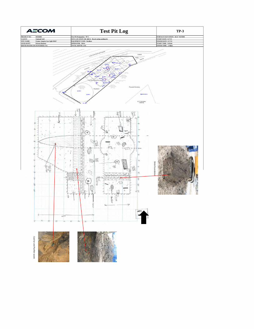
TP-3
PROJECT NO: SURFACE ELEVATION: 46.51' NAVD88
CLIENT: START DATE: 11/7/13
SITE NAME: FINISH DATE: 11/7/13
GEOLOGIST: START TIME: 8:45am
DEPTH WATER ENCOUNTERED: NA FINISH TIME: 2:30pm
Kristen Barbour
Former Jamaica Gas Light MGP
60144468
National Grid
Test Pit Log
TOTAL DEPTH: 14 ft
OPERATOR: Zebra
EQUIPMENT USED: Backhoe
SITE LOCATION OR AREA: Royal carting parking lot
Test Pit Designation: TP-3
Coal tar and Purifier waste
Brick Foundation

Project Name:
Project Number:
Date Pre-Cleared:
Date Started/Completed:
Drilling Company:
Drilling Method:
Sampling Method: Ground Elevation:
Total Depth:
Logged By:
0
-1
-2
-3
-4
-5
-6
-7
-8
-9
-10
-11
-12
-13
-14
-15
-16
-17
-18
-19
-20
-21
-22
Page 1 of 2D
epth
(ft
)
Rec
over
y (
ft)
PID
(ppm
)
Sam
ple
ID
Inte
rval
Lit
holo
gy
U.S
.C.S
Geologic Description
Boring ID:
Notes:
Jamaica Former Holder Station
60144411-210
Fenley and Nicol
Impac
ts
Water Level:
Client:
Boring Diameter: Converted To Well (Y/N):
Well ID:
Wel
l
Definitions:
Sam
ple
d
1) NA - Not Applicable
2) ft - feet
3) bgs - below ground surface
4) U.S.C.S.- Unified Soil Classification System
8) ppm - parts per million
6) SAA - Same As Above
7) PID - Photo Ionization Detector
5) NAVD 88 - North American Vertical Datum of 1988
9) NAPL - Non-Aqueous Phase Liquid
5 ft Macro-Core®
Const
ruct
ion
National Grid
0-0.5 ft bgs: CONCRETE
0.5-2.5 ft bgs: FILL: fine grained sand, ~20% silt, ~20% fine angular gravel,<5% wood, brick, and glass debris, dry, brown, no odor.
2.5-5 ft bgs: SAA, ~20% wood, brick and glass debris.
5-10 ft bgs: FILL: medium to fine grained sand, ~20% silt, ~20% coarsesubangular gravel, dry, brown, no odor.
10-11 ft bgs: SAA.
11-12 ft bgs: CLAY AND SILTY CLAY OF LOW PLASTICITY (CL): silt,~25% clay, moist, orange-tan, no odor.
12-15 ft bgs: WELL GRADED SAND (SW): medium to fine grained sand,coarse subangular gravel up to 2 inches in diameter, moist, wet at 13.5 ft bgs,brown, no odor.
15-20 ft bgs: WELL GRADED SAND (SW): coarse to fine grained sand,~10% coarse subangular gravel, wet, brown, no odor.
20-25 ft bgs: SAA.
0.8
0.1
0.7
1.6
1.5
1.8
1.3
1.8
Direct Push
5.0'/5.0'
3.0'/5.0'
2.5'/5.0'
3.5'/5.0'
5.0'/5.0'
SB-1(2.5-5)
+ms/msd
SB-1(10-12)
Fill
ML
SW
SB-1 / MW-1
February 20/21, 2012
33.65' NAVD 88
45 ft bgs
Jessica Ehlen
February 20, 2012
~13.5 ft bgs
3 3/16 inch Yes
MW-1
Location was pre-cleared by hand from 0-5 ft bgs.
Impacts include visual and olfactory observations.
Boring collapsed from 45-25.5 ft bgs, when rods were pulled.
A 1 inch pre-packed well was installed at this location from
13.5 to 23.5 ft bgs.

Project Name:
Project Number:
Date Pre-Cleared:
Date Started/Completed:
Drilling Company:
Drilling Method:
Sampling Method: Ground Elevation:
Total Depth:
Logged By:
-23
-24
-25
-26
-27
-28
-29
-30
-31
-32
-33
-34
-35
-36
-37
-38
-39
-40
-41
-42
-43
-44
-45
Page 2 of 2D
epth
(ft
)
Rec
over
y (
ft)
PID
(ppm
)
Sam
ple
ID
Inte
rval
Lit
holo
gy
U.S
.C.S
Geologic Description
Boring ID:
Notes:
Jamaica Former Holder Station
60144411-210
Fenley and Nicol
Impac
ts
Water Level:
Client:
Boring Diameter: Converted To Well (Y/N):
Well ID:
Wel
l
Definitions:
Sam
ple
d
1) NA - Not Applicable
2) ft - feet
3) bgs - below ground surface
4) U.S.C.S.- Unified Soil Classification System
8) ppm - parts per million
6) SAA - Same As Above
7) PID - Photo Ionization Detector
5) NAVD 88 - North American Vertical Datum of 1988
9) NAPL - Non-Aqueous Phase Liquid
5 ft Macro-Core®
Const
ruct
ion
National Grid
25-28 ft bgs: SAA.
28-30 ft bgs: SAA, light grey, petroleum-like staining, slight petroleum-likeodor.
30-32 ft bgs: WELL GRADED SAND (SW): medium to fine grained sand,~10% coarse grained sand, wet, light brown, slight petroleum-like odor.
32-35 ft bgs: WELL GRADED SAND (SW): coarse to fine grained sand,~15% subrounded gravel, wet, light brown, no odor.
35-40 ft bgs: WELL GRADED SAND (SW): medium to fine grained sand,~5% coarse grained sand, wet, light brown, no odor.
40-42.5 ft bgs: SAA.
42.5-45 ft bgs: WELL GRADED SAND (SW): coarse to fine grained sand,~10% fine subrounded gravel, wet, light brown, no odor.
END OF BORING 45 ft bgs.
2.7
4.5
19.5
9.6
13.5
1.5
3.2
1.9
1.5
Direct Push
5.0'/5.0'
5.0'/5.0'
5.0'/5.0'
5.0'/5.0'
SB-1(28-30)dup-1
SB-1(30-32)
SB-1(35-37.5)
SB-1(42.5-45)
SB-1 / MW-1
February 20/21, 2012
33.65' NAVD 88
45 ft bgs
Jessica Ehlen
February 20, 2012
~13.5 ft bgs
3 3/16 inch Yes
MW-1
Location was pre-cleared by hand from 0-5 ft bgs.
Impacts include visual and olfactory observations.
Boring collapsed from 45-25.5 ft bgs, when rods were pulled.
A 1 inch pre-packed well was installed at this location from
13.5 to 23.5 ft bgs.
(MW-11 for Jamaica MGP)

AECOM Interim Site Management Plan
Site Management Plan, Site #241063
APPENDIX B
Site Management Form

Site-Wide Inspection Form, Site #241063
NATIONAL GRID FORMER JAMAICA GAS LIGHT COMPANY MANUFACTURED GAS PLANT SITE
QUEENS, NEW YORK SITE NO. 241063
SITE-WIDE INSPECTION FORM
Site Addresses: ________________________________________________________________________
Date and Time of Inspection: _____________________________________________________________
Inspector (Name, Title, and Affiliation): _____________________________________________________
Weather Conditions: ____________________________________________________________________
Describe repairs, maintenance, or corrective actions implemented since previous inspection:
_____________________________________________________________________________________
_____________________________________________________________________________________
_____________________________________________________________________________________
_____________________________________________________________________________________
_____________________________________________________________________________________
ATTACH PHOTOGRAPHS OF AREAS OR ITEMS INSTALLED, REPAIRED, OR REPLACED General Site Conditions: Acceptable Unacceptable Pavement and Sidewalk
Building and/or Foundation Cover
Vegetative Cover (if applicable)

Site-Wide Inspection Form, Site #241063
Site Cover System: Any signs/evidence of ground-intrusive activities (e.g., excavating, trenching, etc.), soil disturbance regardless of quantity/extent, erosion, settlement, or if applicable, bare or sparsely-vegetated areas? ___ No ___ Yes If yes, please describe: _____________________________________________________________________________________ _____________________________________________________________________________________ _____________________________________________________________________________________ _____________________________________________________________________________________
ATTACH PHOTOGRAPHS OF AREAS OF DISTURBANCE
Any signs/evidence of use of the Site in a manner inconsistent with the previous Site uses? ___ No ___ Yes If yes, please describe: _____________________________________________________________________________________ _____________________________________________________________________________________ _____________________________________________________________________________________ _____________________________________________________________________________________
ATTACH PHOTOGRAPHS OF AREAS OF NON-COMPLIANCE
Describe any repairs, maintenance, or corrective actions required to correct observed deficiencies: _____________________________________________________________________________________ _____________________________________________________________________________________ _____________________________________________________________________________________ _____________________________________________________________________________________ ATTACH PHOTOGRAPHS OF AREAS OF DEFICIENT AREAS OR ITEMS OBSERVED DURING THE INSPECTION
Inspector’s Signature: Date: _________________________________________________ ___________________

AECOM Interim Site Management Plan
Site Management Plan, Site #241063
APPENDIX C
List of Site Contacts

LIST OF CONTACTS
Name Phone/Email Address Linda M. Myles Associate General Counsel The City University of New York
212-794-5426 [email protected]
Iris Weinshall Vice Chancellor for Facilities Planning, Construction and Management
212-794-5558 [email protected]
Katherine Vater Project Manager, Site Investigation & Remediation National Grid
608-826-3663 [email protected]
William Wu Project Manager NYSDEC
518-402-9662 [email protected]
Joseph Giordano Environmental Land Use Manager, Legal Department National Grid
516-545-4790 [email protected]
Shail Pandya National Grid’s Consultant AECOM
212-377-8708 [email protected]
AECOM Interim Site Management Plan
Site Management Plan, Site #241063
APPENDIX D
Excavation Work Plan
Prepared for: National Grid One Metro Tech Center Brooklyn, New York 11201
Excavation Work Plan
(Appendix D of the Interim Site Management Plan)
Former Jamaica Gas Light Company Manufactured Gas Site Queens, New York NYSDEC Site No.: 241063 Order on Consent Index #: A2-0552-0606
AECOM Environment
Appendix D - Excavation Work Plan.docx July 2018
i
Contents
Notifications ................................................................................................................... 1-1 1.0
Excavation Work Plan ................................................................................................... 2-1 2.02.1 Soil Screening Methods ....................................................................................................... 2-1
2.2 Soil Staging Method ............................................................................................................. 2-1
2.3 Materials Excavation and Load Out .................................................................................... 2-2
2.4 Materials Transport Off-site ................................................................................................. 2-2
2.5 Materials Disposal Off-site ................................................................................................... 2-3
2.6 Materials Reuse On-site ...................................................................................................... 2-3
2.7 Fluids Management ............................................................................................................. 2-4
2.8 Cover System Restoration................................................................................................... 2-4
2.9 Backfill from Off-site Sources .............................................................................................. 2-5
2.10 Stormwater Pollution Prevention ......................................................................................... 2-5
2.11 Excavation Contingency Plan .............................................................................................. 2-6
2.12 Community Air Monitoring Plan ........................................................................................... 2-6
2.13 Odor Control Plan ................................................................................................................ 2-7
2.14 Dust Control Plan ................................................................................................................. 2-7
2.15 Other Nuisances .................................................................................................................. 2-8

AECOM Environment
Appendix D - Excavation Work Plan.docx July 2018
i
List of Acronyms ASP Analytical Services Protocol
C&D Construction and Debris
CCS Composite Cover System
COC Compounds of Concern
DER-10 NYSDEC DER-10 Technical Guidance for Site Investigation and Remediation
DOT Department of Transportation
EC Engineering Controls
EWP Excavation Work Plan
HASP Health and Safety Plan
NYCRR New York Codes Rules and Regulations
ISMP Interim Site Management Plan
NYC New York City
NYS New York State
NYSDEC New York State Department of Environmental Conservation
NYSDOH New York State Department of Health
OSHA Occupational Safety and Health Administration
PCBs Polychlorinated Biphenyls
PPE Personal Protective Equipment
QA Quality Assurance
QC Quality Control
SCO Soil Cleanup Objectives
ISMP Interim Site Management Plan
SPDES State Pollution Discharge Elimination System
SVOCs Semi-volatile Organic Compounds
TCL Target Compound List
TCLP Toxicity Characteristics Leaching Procedure
VOCs Volatile Organic Compounds
USEPA United States Environmental Protection Agency
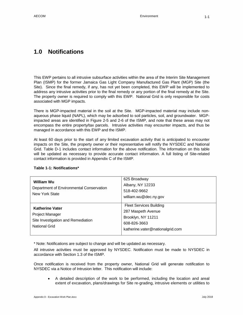
AECOM Environment
Appendix D - Excavation Work Plan.docx July 2018
1-1
Notifications 1.0
This EWP pertains to all intrusive subsurface activities within the area of the Interim Site Management Plan (ISMP) for the former Jamaica Gas Light Company Manufactured Gas Plant (MGP) Site (the Site). Since the final remedy, if any, has not yet been completed, this EWP will be implemented to address any intrusive activities prior to the final remedy or any portion of the final remedy at the Site. The property owner is required to comply with this EWP. National Grid is only responsible for costs associated with MGP impacts.
There is MGP-impacted material in the soil at the Site. MGP-impacted material may include non-aqueous phase liquid (NAPL), which may be adsorbed to soil particles, soil, and groundwater. MGP-impacted areas are identified in Figure 2-5 and 2-6 of the ISMP, and note that these areas may not encompass the entire property/tax parcels. Intrusive activities may encounter impacts, and thus be managed in accordance with this EWP and the ISMP.
At least 60 days prior to the start of any limited excavation activity that is anticipated to encounter impacts on the Site, the property owner or their representative will notify the NYSDEC and National Grid. Table D-1 includes contact information for the above notification. The information on this table will be updated as necessary to provide accurate contact information. A full listing of Site-related contact information is provided in Appendix C of the ISMP.
Table 1-1: Notifications*
William Wu Department of Environmental Conservation New York State
625 Broadway Albany, NY 12233 518-402-9662 [email protected]
Katherine Vater Project Manager Site Investigation and Remediation National Grid
Fleet Services Building 287 Maspeth Avenue Brooklyn, NY 11211 608-826-3663 [email protected]
* Note: Notifications are subject to change and will be updated as necessary. All intrusive activities must be approved by NYSDEC. Notification must be made to NYSDEC in accordance with Section 1.3 of the ISMP.
Once notification is received from the property owner, National Grid will generate notification to NYSDEC via a Notice of Intrusion letter. This notification will include:
• A detailed description of the work to be performed, including the location and areal extent of excavation, plans/drawings for Site re-grading, intrusive elements or utilities to

AECOM Environment
Appendix D - Excavation Work Plan.docx July 2018
1-2
be installed below the soil cover, estimated volumes of impacted soil to be excavated and any work that may impact the engineering control;
• Whether proposed activities will require dewatering, proposed containment of dewatering liquids and planned disposal options for dewatering liquids;
• A summary of environmental conditions anticipated to be encountered in the work areas, including the nature and concentration levels of contaminants of concern, potential presence of grossly impacted media, and plans for any pre-construction sampling;
• A schedule for the work, detailing the start and completion of all intrusive work;
• A summary of the applicable components of this EWP;
• A statement from the party performing the work that the work will be performed in compliance with this EWP and 29 Code of Federal Regulations (CFR) 1910.120;
• A copy of the contractor’s HASP, in electronic format (a sample HASP is provided in Appendix E of this ISMP);
• Identification of disposal facilities for potential waste streams; and
• Identification of sources of any anticipated backfill, along with all required chemical testing results.
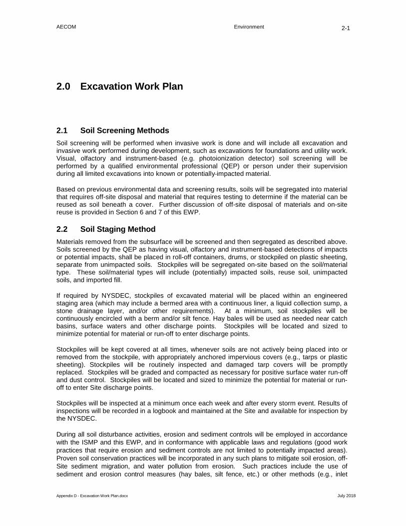
AECOM Environment
Appendix D - Excavation Work Plan.docx July 2018
2-1
Excavation Work Plan 2.0
2.1 Soil Screening Methods Soil screening will be performed when invasive work is done and will include all excavation and invasive work performed during development, such as excavations for foundations and utility work. Visual, olfactory and instrument-based (e.g. photoionization detector) soil screening will be performed by a qualified environmental professional (QEP) or person under their supervision during all limited excavations into known or potentially impacted material.
Based on previous environmental data and screening results, soils will be segregated into material that requires off-site disposal and material that requires testing to determine if the material can be reused as soil beneath a cover. Further discussion of off-site disposal of materials and on-site reuse is provided in Section 6 and 7 of this EWP.
2.2 Soil Staging Method Materials removed from the subsurface will be screened and then segregated as described above. Soils screened by the QEP as having visual, olfactory and instrument-based detections of impacts or potential impacts, shall be placed in roll-off containers, drums, or stockpiled on plastic sheeting, separate from unimpacted soils. Stockpiles will be segregated on-site based on the soil/material type. These soil/material types will include (potentially) impacted soils, reuse soil, unimpacted soils, and imported fill.
If required by NYSDEC, stockpiles of excavated material will be placed within an engineered staging area (which may include a bermed area with a continuous liner, a liquid collection sump, a stone drainage layer, and/or other requirements). At a minimum, soil stockpiles will be continuously encircled with a berm and/or silt fence. Hay bales will be used as needed near catch basins, surface waters and other discharge points. Stockpiles will be located and sized to minimize potential for material or run-off to enter discharge points.
Stockpiles will be kept covered at all times, whenever soils are not actively being placed into or removed from the stockpile, with appropriately anchored impervious covers (e.g., tarps or plastic sheeting). Stockpiles will be routinely inspected and damaged tarp covers will be promptly replaced. Stockpiles will be graded and compacted as necessary for positive surface water run-off and dust control. Stockpiles will be located and sized to minimize the potential for material or run-off to enter Site discharge points.
Stockpiles will be inspected at a minimum once each week and after every storm event. Results of inspections will be recorded in a logbook and maintained at the Site and available for inspection by the NYSDEC.
During all soil disturbance activities, erosion and sediment controls will be employed in accordance with the ISMP and this EWP, and in conformance with applicable laws and regulations (good work practices that require erosion and sediment controls are not limited to potentially impacted areas). Proven soil conservation practices will be incorporated in any such plans to mitigate soil erosion, off-Site sediment migration, and water pollution from erosion. Such practices include the use of sediment and erosion control measures (hay bales, silt fence, etc.) or other methods (e.g., inlet

AECOM Environment
Appendix D - Excavation Work Plan.docx July 2018
2-2
protection near catch basins, surface waters, and/or other discharge points) to prevent soil from entering these features. At a minimum, appropriate temporary erosion and sediment control measures (hay bales, silt fence, etc.) will be installed and maintained around all impacted and potentially-impacted soil/fill stockpiles and bare soil surfaces during work.
2.3 Materials Excavation and Load Out A QEP or person under their supervision will oversee all intrusive work at the Site and the excavation and load-out of all excavated material.
To the extent that they perform work under this EWP, the property owner and their contractors are responsible for safe execution of all work, including the structural integrity of excavations and structures, such as subsurface utilities and buildings that may be affected by excavations.
The presence of utilities and easements on the Site will be investigated. Based on this investigation, it will be determined whether a risk or impediment to the work planned under this EWP is posed by utilities or easements on the Site.
Loaded vehicles leaving the Site will be appropriately lined, tarped, securely covered, manifested, and placarded in accordance with appropriate Federal, State, local, and New York State Department of Transportation (NYSDOT) requirements (and all other applicable transportation requirements).
A truck wash will be operated on-Site, as appropriate. The QEP will be responsible for ensuring that all outbound trucks will be washed at the truck wash before leaving the Site until the activities performed under this section are complete truck wash waters will be collected and disposed off-site in an appropriate manner.
The property owner’s QEP will be responsible for ensuring that all egress points for truck and equipment transport from the Site are clean of dirt and other materials derived from the Site during intrusive excavation activities. Locations where vehicles enter or exit the Site shall be inspected daily for evidence of off-site soil tracking. If there is evidence of off-site soil tracking, trucks will be cleaned of loose soil found on the outside of the vehicle and/or tires prior to existing the Site. Cleaning of the adjacent streets will be performed as needed to maintain a clean condition with respect to Site-derived materials.
2.4 Materials Transport Off-site All transport of materials will be performed by licensed haulers in accordance with appropriate local, State, and Federal regulations, including 6 NYCRR Part 364. Haulers will be appropriately licensed and trucks properly placarded.
Material transported by trucks exiting the Site will be secured with tight-fitting water-proof tarpaulin covers. At a minimum, trucks transporting any material off-site shall be water-tight and structurally sound, have cover systems, and functional, locking tailgates. Loose-fitting canvas-type and mesh truck covers will be prohibited. If loads contain wet material capable of producing free liquid, truck liners will be used. All trucks transporting impacted material will be decontaminated prior to leaving the Site. Decontamination water, if any, will be collected and disposed of off-site in an appropriate manner.
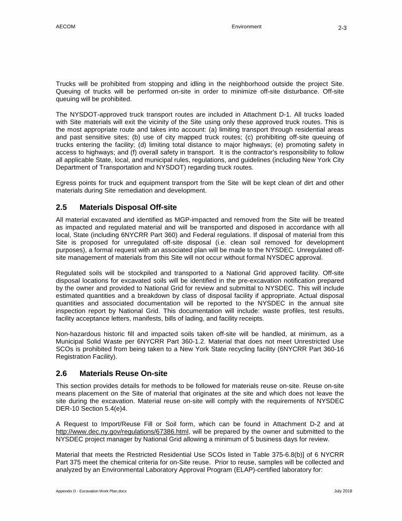
AECOM Environment
Appendix D - Excavation Work Plan.docx July 2018
2-3
Trucks will be prohibited from stopping and idling in the neighborhood outside the project Site. Queuing of trucks will be performed on-site in order to minimize off-site disturbance. Off-site queuing will be prohibited.
The NYSDOT-approved truck transport routes are included in Attachment D-1. All trucks loaded with Site materials will exit the vicinity of the Site using only these approved truck routes. This is the most appropriate route and takes into account: (a) limiting transport through residential areas and past sensitive sites; (b) use of city mapped truck routes; (c) prohibiting off-site queuing of trucks entering the facility; (d) limiting total distance to major highways; (e) promoting safety in access to highways; and (f) overall safety in transport. It is the contractor’s responsibility to follow all applicable State, local, and municipal rules, regulations, and guidelines (including New York City Department of Transportation and NYSDOT) regarding truck routes.
Egress points for truck and equipment transport from the Site will be kept clean of dirt and other materials during Site remediation and development.
2.5 Materials Disposal Off-site All material excavated and identified as MGP-impacted and removed from the Site will be treated as impacted and regulated material and will be transported and disposed in accordance with all local, State (including 6NYCRR Part 360) and Federal regulations. If disposal of material from this Site is proposed for unregulated off-site disposal (i.e. clean soil removed for development purposes), a formal request with an associated plan will be made to the NYSDEC. Unregulated off-site management of materials from this Site will not occur without formal NYSDEC approval.
Regulated soils will be stockpiled and transported to a National Grid approved facility. Off-site disposal locations for excavated soils will be identified in the pre-excavation notification prepared by the owner and provided to National Grid for review and submittal to NYSDEC. This will include estimated quantities and a breakdown by class of disposal facility if appropriate. Actual disposal quantities and associated documentation will be reported to the NYSDEC in the annual site inspection report by National Grid. This documentation will include: waste profiles, test results, facility acceptance letters, manifests, bills of lading, and facility receipts.
Non-hazardous historic fill and impacted soils taken off-site will be handled, at minimum, as a Municipal Solid Waste per 6NYCRR Part 360-1.2. Material that does not meet Unrestricted Use SCOs is prohibited from being taken to a New York State recycling facility (6NYCRR Part 360-16 Registration Facility).
2.6 Materials Reuse On-site This section provides details for methods to be followed for materials reuse on-site. Reuse on-site means placement on the Site of material that originates at the site and which does not leave the site during the excavation. Material reuse on-site will comply with the requirements of NYSDEC DER-10 Section 5.4(e)4.
A Request to Import/Reuse Fill or Soil form, which can be found in Attachment D-2 and at http://www.dec.ny.gov/regulations/67386.html, will be prepared by the owner and submitted to the NYSDEC project manager by National Grid allowing a minimum of 5 business days for review.
Material that meets the Restricted Residential Use SCOs listed in Table 375-6.8(b)] of 6 NYCRR Part 375 meet the chemical criteria for on-Site reuse. Prior to reuse, samples will be collected and analyzed by an Environmental Laboratory Approval Program (ELAP)-certified laboratory for:

AECOM Environment
Appendix D - Excavation Work Plan.docx July 2018
2-4
• Total VOCs via U.S. Environmental Protection Agency (EPA) Method 8260 • Total SVOCs via EPA Method 8270C • Polychlorinated biphenyls (PCBs) via EPA Method 8082/8082A/8080 • Total Petroleum Hydrocarbons (TPH) Diesel Range Organics/Gasoline Range
Organics (DRO/GRO) via EPA Method 8015M (expanded to C44) • Total cyanide via EPA Method 9010/9014 • Total Metals (RCRA+Cu, Ni, Zn, Va, Cn HexChrome) via EPA Method 6010B and
6010 • TCLP Metals via EPA Method 1311 • Ignitability via EPA Method 1030 and 1010A • Corrosivity via EPA Method 1030 and 9040C • Reactivity via EPA Method 1110 and SW846 Ch7.5 • Total Sulfur via American Society for Testing and Materials (ASTM) Standard
D129 • TCLP Volatile Organics via EPA Method 8260B • TCLP Semi-volatile Organics via EPA Method 8270D • TCLP Herbicides/TCLP Pesticides via EPA Method 1311 • Total Organic Halides via EPA Method 9023B • Total Mercury via EPA Method 7471.
The QEP will ensure that procedures defined for materials reuse in this EWP are followed and that unacceptable material does not remain on-Site. Impacted soil that is acceptable for reuse on-site will be placed in stockpiles consistent with Section 3 of this EWP, prior to placement below the demarcation layer or impervious surface, and will not be reused within a cover soil layer, within landscaping berms, or as backfill for subsurface utility lines.
Any demolition material proposed for reuse on-Site will be sampled for asbestos and the results will be reported to the NYSDEC for acceptance. Concrete crushing or processing on-site will not be performed without prior NYSDEC approval. Organic matter (wood, roots, stumps, etc.) or other solid waste derived from clearing and grubbing of the Site will not be reused on-Site.
2.7 Fluids Management All impacted liquids to be removed from the Site, including but not limited to, excavation dewatering, decontamination waters (including truck wash) and groundwater monitoring well purge and development waters, will be handled, transported and disposed in accordance with applicable local, State, and Federal regulations. Impacted liquids removed from the Site will be disposed of at a National Grid approved disposal facility. Dewatering, purge and development fluids will not be recharged back to the land surface or subsurface of the Site, and will be managed off-site, unless prior approval is obtained from NYSDEC.
Discharge of water generated during construction activities to surface waters (i.e. a local pond, stream or river) will be performed under a State Pollutant Discharge Elimination System (SPDES) permit. Discharge of water generated during construction activities into sanitary or combined sewers will require approval from the NYSDEC and the New York City Department of Environmental Protection (NYCDEP) and will be performed under a NYCDEP dewatering permit.
2.8 Cover System Restoration After the completion of soil removal and any other intrusive activities the cover system will be restored in a manner that complies with the conditions following the Remedial Investigation and the ISMP. The existing cover system is comprised of a minimum of 1 inch of asphalt pavement. The

AECOM Environment
Appendix D - Excavation Work Plan.docx July 2018
2-5
demarcation layer, consisting of orange snow fencing material will be installed to provide a visual reference to the top of the remaining impacted soils, which are the soils that requires adherence to special conditions for disturbance of impacted soils defined in this EWP. The property owner shall not change the type of cover system following excavation without prior written permission from NYSDEC.
2.9 Backfill from Off-site Sources All materials proposed for import onto the Site will be approved by National Grid’s QEP and will be in compliance with provisions in this EW P prior to receipt at the Site. A Request to Import/Reuse Fill or Soil form, which can be found in Attachment D-2 and at http://www.dec.ny.gov/regulations/67386.html, will be prepared by the owner and submitted to the NYSDEC project manager by National Grid allowing a minimum of 5 business days for review. This will include analytical sampling of the borrow source or existing documentation of agency approvals of the source (i.e. NYSDOT virgin source certification and latest analytical sampling results). NYSDEC approval must be received before material is imported to the Site.
Material from industrial sites, spill sites, or other environmental remediation sites or potentially impacted sites will not be imported to the Site.
All imported soils will meet the backfill and cover soil quality standards established in 6NYCRR 375-6.7(d). Based on an evaluation of the land use, protection of groundwater and protection of ecological resources criteria, the resulting soil quality standards are 6 NYCRR Part 375 Restricted Use Protection of Public Health Restricted Residential Use Site Clean-up Objectives (SCOs) and Protection of Groundwater SCOs. Soils that meet exempt fill requirements under 6 NYCRR Part 360, but do not meet backfill or cover soil objectives for this Site, will not be imported onto the Site without prior approval by NYSDEC. Solid waste will not be imported onto the Site.
Samples will be collected from imported fill in accordance with the analytical sampling requirements of DER-10 and the frequency requirements in NYSDEC’s Soil Cleanup Guidance, CP-51. At a minimum, samples will be analyzed for inorganics, pesticides, PCBs, VOCs and SVOCs in accordance with the analytes for the Restricted Residential Use SCOs listed in Table 375-6.8(a) of 6 NYCRR Part 375. The frequency and type of the sampling (i.e. discrete or composite) will be based on the quantity of material imported in accordance with Table 4 of CP-51.
Trucks entering the Site with imported soils will be securely covered with tight fitting covers. Imported soils will be stockpiled separately from excavated materials and covered to prevent dust releases (see Section D-3).
2.10 Stormwater Pollution Prevention For excavations less than 1 acre that are not part of a larger disturbance, the following stormwater management practices will be completed in accordance with the requirements in the New York State Stormwater Management Design Manual, latest revision.
Silt fencing and/or hay bale checks will be installed around the entire perimeter of the construction area and will be inspected once a week and after every storm event. Results of inspections will be recorded in a logbook and maintained at the Site and available for inspection by the NYSDEC. All necessary repairs shall be made immediately.
Accumulated sediments will be removed as required to keep the silt fencing and/or hay bale check functional. All undercutting or erosion of the silt fence toe anchor shall be repaired immediately

AECOM Environment
Appendix D - Excavation Work Plan.docx July 2018
2-6
with appropriate backfill materials. Manufacturer's recommendations will be followed for replacing silt fencing damaged due to weathering.
Erosion and sediment control measures identified in the EWP shall be observed to ensure that they are operating correctly. Where discharge locations or points are accessible, they shall be inspected to ascertain whether erosion control measures are effective in preventing significant impacts to receiving waters.
If the work on the property is part of a larger plan that disturbs more than 1 acre, the property owner must obtain coverage under the NYSDEC SPDES General Permit for Stormwater Discharges from Construction Activity.
2.11 Excavation Contingency Plan Identification of unknown or unexpected potentially impacted media identified by screening during invasive site work will be promptly communicated by phone to National Grid and National Grid will notify NYSDEC’s Project Manager. Reportable quantities of petroleum product will also be reported to the NYSDEC spills hotline. These findings will be also included in the annual site inspection report by National Grid.
If underground tanks or other previously unidentified contaminant sources are found during excavation, excavation activities will be suspended until sufficient equipment is mobilized to address the condition.
If potentially MGP-impacted materials are encountered at unexpected depth or locations, Site activities will be suspended and National Grid will be notified and will evaluate the observed conditions in a manner and timeframe that does not interfere with the construction schedule, to the extent reasonably feasible. National Grid may determine that laboratory testing is required to evaluate the observed conditions for concentrations and characteristics. If the encountered materials are determined to be MGP-impacted, then the encountered materials will be segregated and stockpiled for disposal at a National Grid approved facility.
Sampling will be performed on product, sediment and surrounding soils, etc. as necessary to determine the nature of the material and proper disposal method. Chemical analysis will be performed for a full list of analytes (TAL metals; Target Compound List (TCL) volatiles and semi-volatiles, pesticides and PCBs, and free cyanide). If future sampling results provide a sufficient justification to limit the list of analytes, a reduced list of analytes will be proposed to the NYSDEC for approval prior to sampling.
2.12 Community Air Monitoring Plan The Community Air Monitoring Plan (CAMP) will consist of real-time monitoring and an action level reporting system. A CAMP will be conducted during all intrusive activities on the Site that is located within areas of MGP-impacted material. Location(s) of MGP-impacted material is/are shown in Figure 2-5 and 2-6. Air sampling stations locations will be chosen based on generally prevailing wind conditions and adjusted on a daily or more frequent basis based on actual wind directions to provide an upwind and at least two downwind monitoring stations. If a sensitive receptor, such as a school, day care or residential area is adjacent to the site, a fixed monitoring station will be located at that site perimeter, regardless of wind direction, and discussed in the CAMP.

AECOM Environment
Appendix D - Excavation Work Plan.docx July 2018
2-7
Exceedances of action levels listed in the CAMP (Appendix F of the ISMP) will be reported to NYSDEC and NYSDOH Project Managers.
2.13 Odor Control Plan Odors which derive from site impacts may cause a nuisance to site workers and the surrounding community, even though the impacts are at levels well below the safety limits defined in the CAMP. This odor control plan is intended to control emissions of nuisance odors off-site. Specific odor control methods to be used on a routine basis will include all reasonable and necessary means as described in the following paragraph. If nuisance odors are identified at the Site boundary, or if odor complaints are received, work will be halted and the source of odors will be identified and corrected. Work will not resume until all nuisance odors have been abated. NYSDEC and NYSDOH will be notified by National Grid of all odor events and of any other complaints about the project. Implementation of all odor controls, including the halt of work, is the responsibility of the contractor, and any measures that are implemented will be discussed in the annual site inspection report.
All necessary means will be employed to prevent on- and off-site nuisances. At a minimum, these measures will include: (a) limiting the area of open excavations and size of soil stockpiles; (b) shrouding open excavations with tarps and other covers; and (c) using foams/sprays to cover exposed odorous soils. If odors develop and cannot be otherwise controlled, additional means to eliminate odor nuisances will include: (d) direct load-out of soils to trucks for off-site disposal; (e) use of chemical odorants in spray or misting systems at site boundaries; and, (f) use of staff to monitor odors in surrounding neighborhoods.
If nuisance odors develop during intrusive work that cannot be corrected, or where the control of nuisance odors cannot otherwise be achieved due to on-site conditions or close proximity to sensitive receptors, odor control will be achieved by sheltering the excavation and handling areas in a temporary containment structure equipped with appropriate air venting/filtering systems.
2.14 Dust Control Plan Dust which derives from site impacts may cause a nuisance to some site workers and the surrounding community, even though the impacts are at levels well below the safety limits defined in the CAMP. Dust monitoring will be performed in accordance with the project-specific CAMP. Real-time air monitoring will be implemented at representative upwind and downwind locations near the intrusive activities for particulate matter less than 10 microns in diameter (PM10). Perimeter monitoring will include the use of a real-time particulate monitoring instrument. As required by the NYSDOH Generic CAMP, real-time airborne particulate monitoring will be conducted continuously during intrusive activities, including soil excavation, backfilling, and related soil handling. Fugitive dust mitigation will be visually assessed during work activities, and reason able dust suppression techniques will be used during Site activities that may generate dust.
A dust suppression plan that addresses dust management during invasive on-site work will include, at a minimum, the items listed below:
• Dust suppression will be achieved through the use of a dedicated on-Site water truck for road wetting. The truck will be equipped with a water cannon capable of spraying water directly onto off-road areas including excavations and stockpiles.
• Clearing and grubbing of larger sites will be done in stages to limit the area of exposed, unvegetated soils vulnerable to dust production.
• Gravel will be used on roadways to provide a clean and dust-free road surface.
AECOM Environment
Appendix D - Excavation Work Plan.docx July 2018
2-8
• On-site roads will be limited in total area to minimize the area required for water truck sprinkling. Water in the truck should be only from a verified clean source. On-site groundwater cannot be used for dust mitigation.
If complaints are received for dust, the contractor will take the appropriate response actions for dust suppression.
2.15 Other Nuisances The following items may be necessary depending on the type of wastes present, the location of the Site and other site-specific concerns. These plans are generally not required for submission to the NYSDEC, but are generally required as part of construction.
A plan for rodent control will be developed and utilized by the contractor prior to and during Site clearing and Site grubbing, and during all remedial work.
A plan will be developed and utilized by the contractor for all remedial work to ensure compliance with local noise control ordinances.

AECOM Environment
Appendix D - Excavation Work Plan.docx July 2018
2-9
Attachment D-1

NATIONAL GRIDFORMER MGP, JAMAICA, NY
INTERIM SITE MANAGEMENT PLANTRUCK ROUTE
D-1DATE: 03/22/2018 DRWN: TL JOB #: 60144468
M:\N
ation
al Gr
id\Ja
maica
MGP
Site\
GIS\M
xd\At
tachm
ent D
-1 Tru
ck R
oute.
mxd
(Nati
onal
Grid
on U
SNYC
S01\E
nviro
nmen
t\ (Y)
)
INSET 1
INSET 2
Flatbush Ave
Mc D
onald
Ave
§̈¦278 §̈¦678
§̈¦878
§̈¦478
§̈¦495
§̈¦278§̈¦278
§̈¦278
§̈¦278
§̈¦278
§̈¦678
§̈¦478
UV907
UV27
UV908
UV25
UV878
UV900
UV9UV24
UV907
UV24
UV907
UV878
UV27UV908
UV907
UV25UV907
UV907
UV908
UV878
UV27
UV27
UV27
UV908
UV25
UV907
U
Atlantic Ave
4th Ave
5th Ave
P
D
Liberty Ave
Myrtle Ave
Fulton St
86th St
Ocean Ave
Linden Blvd
Utica Ave
65th St
Bedford Ave
Jamaica Ave
Flatlands Ave
Metropolitan Ave
Flushing Ave
Bay Pk
y
18th A
ve
Eastern Pky
80th St
6th Ave
Merrick Blvd
Farm
ersBlv
d
9th St
Dekalb Ave
Rockaway Blvd
Remsen Ave
Eliot Ave
Kings Hwy
Rockaway Pky
Woodhaven Blvd
3rd Av
e
C
Sutphin Blvd
Lafayette Ave
New York Ave
Grand St
Sprin
gfield Blv
d
Union Tpke
Coney Island Ave
Bay Ridge Pky
Lefferts Blvd
Henry
St
B
Broadway
Nostrand Ave
8th Av
e
Guy R Brewer Blvd
Grand Ave
164thSt
7th Ave
A
Fort HamiltonPky
Smith
St
Washington Ave
Clinto
n St
Bushwick Ave
Berry St
Francis Lewis Blvd
Park Ave
69th St
Pennsylvania Ave
44th St
Union Ave
Houston St
New
Utrec
ht Av
e
Lewis Ave
Marcy AveManhattan Ave
Clarendon Rd
39th St
Parsons Blvd
Main St
Canal St
Carlton Ave
69th Rd
Prospect Ave
Drigg
s Ave
Bowe
ry
Etna St
Ralph Ave
71st
Ave
Baisley Blvd
Lafay
ette S
t
Cropsey Ave
Cooper Ave
Lee Ave
South Rd
Hollis AveUnion Trnpike
Fresh Pond Rd
Hillside Ave
Gerritsen Ave
Allen
St
Beverly Rd
Stuyvesant Ave
Central AveVa
rick S
t
Foster AveCoop
er St
Gree
nwich
St
Cypress Hills St
Malcolm X Blvd
Mott Ave
Midla
nd Pky
168th St
Water St
Churc
h St
Euclid Ave
Conduit Blvd
Sheri
dan B
lvd
108th St
188th St
Stillwell Ave Beach Channel D
r
Colum
bia St
Ditmas Ave
Prospe
ct Park
Bay 8th
St
Livingston St
92nd St
Church Ave
Bayview Ave
67th St
Kingsland Ave
58th
St
Yellow
stone Blvd
Cross Bay Blvd
Wall St
61st St
150th
St
Conduit Ave
Hamilton Ave
Home
Lawn
St
Vandervoort Ave
Humboldt St
N 74
th St
Parkside Ave
156th Ave
Nassau St
11th A
ve10th A
ve
Eldert Ln
P ikeSt
Beach 9 th St
Ashland Pl
Trinity
Pl
Cypress Ave
J F K Access Rd
Seaview Ave
Truxton St
Cherry St
Lorraine St
84th R
dPark Row
Cente
rville
St
147th Ave
Howard Ave
New York Blvd
190th St
Kew Gardens RdBushw ick Ave
150th St
Broadw
ay 188th St
Grand St
Kings
Hwy
Bedfo
rdAv
e
7th Av
eMetropolitan Ave
3rd Av
e
Kings
Hw
y
Rockaway Blvd
Hol lis Ave
New York Ave
Cooper Ave
Fulton St
D Broadway
Euclid Ave
Leffe
rts Bl
vd
U nion Tpke
Kings
Hwy
61st St
4LegendTruck Route
0 1 20.5Miles
89 AV
150 ST
101 AV
94 AV
SUTPHIN BL
VAN WYCK EP
LIBERTY AV
97 AV
ARCHER AV
HILLSIDE AV
105 AV
107 AV
95 AV
130 ST
87 RD
SOUTH RD
VAN WYCK EP SR W
106 AV
153 ST144 ST
87 AV
148 ST
160 ST
132 ST131 ST
JAMAICA AV
VAN WYCK EP SR E
161 ST
129 ST
146 ST
138 ST
162 ST
138 PL
WALTHAM ST
134 ST
155 ST
86 RD
163 ST
127 ST
139 ST
102 AV
133 ST
154 ST
PARSONS BL
143 ST
SHORE AV
136 ST
ATLANTIC AV
159 ST156 ST
158 ST
147 PL
145 ST
92 AV
144 PL
157 ST
BEAVER RD
BRISBIN ST
QUEENS BL
REMINGTON ST
88 AV
91 AV
135 ST
87 DR
NO NAME
88 RD
ALLENDALE ST
108 AV
LIVERPOOL ST
PRINCETON STLLOYD RD
90 AV
INWOOD ST
149 ST
126 ST
CRESSKILL PL
ARLINGTON TE
TUCKERTON ST
90 RDMETROPOLITAN AV
LAKE
WOOD AV YATES RD
86 AV
KEW GARDENS RD
LOWE CT
SANDERS PL
VAN WYCK EP ET SB
VAN WYCK EP EN NB
GUINZBURG RD
BURDETTE PL
97 AV
135 ST
NO NAME
90 AV
VAN WYCK EP
138 PL
146 ST
NO NAME
NO NAME
132 ST
91 AV
143 ST
89 AV
153 ST
91 AV
JAMAICA AV
148 ST
139 ST
135 ST
95 AV
90 AV
87 RD
146 ST
149 ST
148 ST
102 AV
89 AV
143 ST
QUEENS BL134 ST
87 AV 148 ST
147 PL
108 AV
132 ST
133 ST
88 AV
157 ST
132 ST
138 ST
NO NAME
87 AV
NO NAME
90 AV
§̈¦678
UV25
Sutphin Blvd
Liberty
Ave
South R
d
A tlantic Ave
Parsons Blvd
4INSET 1
UNION ST
4 AV
COUR
T ST
SMITH
ST
HOYT
ST
STATE ST
CLINT
ON ST
HENR
Y ST
3 ST
ATLANTIC AVDEAN ST
2 ST
1 PL
PACIFIC ST
2 PL
4 PL
BERGEN ST
BQE C
NTG
HY
3 PL
HICKS
ST
BALTIC ST
5 AV
COLU
MBIA
ST
FULTON ST
4 ST
LIVINGSTON ST
BOND
ST
W 9 ST
1 ST
WYCKOFF ST
KANE ST
BUTLER ST
SCHERMERHORN ST
NEVIN
S ST
GOWANUS EP
DE GRAW ST
3 AV
SACKETT ST
AMITY ST
PRESIDENT ST
CONGRESS ST
WILLOUGHBY ST
DOUGLASS ST
GOLD
ST
5 ST
HAMILTON AV
LUQUER ST
MILL ST
WARREN ST
JORALEMON ST
JAY S
T
DE KALB AV
NELSON ST
BRID
GE ST
BQE AP
FLATBUSH AV
ST MARKS PL
VAN
BRUN
T ST
SUMMIT ST
BQE EN NB
TIFFA
NY PL
SIDNE
Y PL
HUNTINGTON ST
FLEE
T ST
LAW
RENC
E ST
BOER
UM PL
STRO
NG PL
FURM
AN ST
CHEE
VER
PL
PEAR
L ST
ADAM
S ST
GARD
EN PL
CARROLL ST
BQE EN SB
WOODHULL ST
NO NA
ME
FAIR ST
RAPELYE ST
GROVE PL
WHITWEL
L PL
BQE E
T SB
HICKS
ST
SUMMIT ST
BQE A
P
NEVIN
S ST
CARROLL ST
DOUGLASS ST
PACIFIC ST
CARROLL ST
BALTIC ST
NELSON ST
GOWANUS EP
1 ST
PRESIDENT ST
BQE A
P
CARROLL ST
BALTIC ST
DE GRAW ST
BOND
ST
HUNTINGTON ST
SACKETT ST
BOND
ST
BUTLER ST
NEVIN
S ST
PRESIDENT ST
WARREN ST
WARREN ST
WARREN ST
3 AVPRESIDENT ST
4INSET 2

AECOM Environment
Appendix D - Excavation Work Plan.docx July 2018
2-10
Attachment D-2
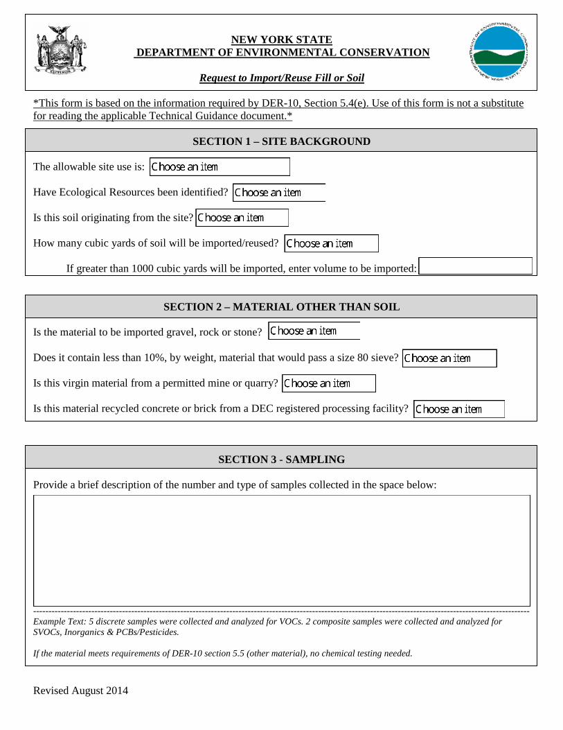
NEW YORK STATE DEPARTMENT OF ENVIRONMENTAL CONSERVATION
Request to Import/Reuse Fill or Soil
*This form is based on the information required by DER-10, Section 5.4(e). Use of this form is not a substitute for reading the applicable Technical Guidance document.*
SECTION 1 – SITE BACKGROUND The allowable site use is: Have Ecological Resources been identified? Is this soil originating from the site? How many cubic yards of soil will be imported/reused? If greater than 1000 cubic yards will be imported, enter volume to be imported:
SECTION 2 – MATERIAL OTHER THAN SOIL Is the material to be imported gravel, rock or stone? Does it contain less than 10%, by weight, material that would pass a size 80 sieve? Is this virgin material from a permitted mine or quarry? Is this material recycled concrete or brick from a DEC registered processing facility?
SECTION 3 - SAMPLING
Provide a brief description of the number and type of samples collected in the space below: ------------------------------------------------------------------------------------------------------------------------------------------------------------------ Example Text: 5 discrete samples were collected and analyzed for VOCs. 2 composite samples were collected and analyzed for SVOCs, Inorganics & PCBs/Pesticides. If the material meets requirements of DER-10 section 5.5 (other material), no chemical testing needed.
Revised August 2014
SECTION 3 CONT’D - SAMPLING
Provide a brief written summary of the sampling results or attach evaluation tables (compare to DER-10, Appendix 5): ------------------------------------------------------------------------------------------------------------------------------------------------------------------ Example Text: Arsenic was detected up to 17 ppm in 1 (of 5) samples; the allowable level is 16 ppm. If Ecological Resources have been identified use the “If Ecological Resources are Present” column in Appendix 5.
SECTION 4 – SOURCE OF FILL Name of person providing fill and relationship to the source: Location where fill was obtained: Identification of any state or local approvals as a fill source: If no approvals are available, provide a brief history of the use of the property that is the fill source: Provide a list of supporting documentation included with this request:
Revised August 2014

The information provided on this form is accurate and complete. _________________________________ _______________
Signature Date
_________________________________ Print Name
_________________________________ Firm
Revised August 2014

AECOM Interim Site Management Plan
Site Management Plan, Site #241063
APPENDIX E
Sample Health and Safety Plan
Prepared for: Submitted by: National Grid AECOM Brooklyn, New York New York, New York 60144468 July 2018
Environment
Sample Health and Safety Plan
(Appendix E of the Interim Site Management Plan)
Former Jamaica Gas Light Company Manufactured Gas Plant Site Jamaica, Queens, New York NYSDEC Site No.: 241063 Order on Consent Index #: A2-0552-0606
Prepared for: Submitted by: National Grid AECOM Brooklyn, New York New York, New York 60144468 July 2018
Environment
Sample Health and Safety Plan
(Appendix E of the Interim Site Management Plan)
Prepared By
Reviewed By
Former Jamaica Gas Light Company Manufactured Gas Plant Site Jamaica, Queens, New York NYSDEC Site No.: 241063 Order on Consent Index #: A2-0552-0606

AECOM Health and Safety Plan
Appendix E - HASP.doc July 2018
i
Contents
1.0 Introduction ................................................................................................................... 1-1
1.1 AECOM Environment Safety Policy ................................................................................... 1-1 1.1.1 Maximum Duration of the Work Day for Field Activities ...................................... 1-1 1.1.2 Short Service Employee ....................................................................................... 1-1
1.2 Health and Safety Plan (HASP) .......................................................................................... 1-1 1.2.1 HASP Purpose ..................................................................................................... 1-1 1.2.2 HASP Applicability ................................................................................................ 1-1
1.3 Organization/Responsibility................................................................................................. 1-2 1.3.1 AECOM Project Manager .................................................................................... 1-2 1.3.2 AECOM Regional Safety, Health & Environment Manager ................................ 1-3 1.3.3 AECOM Site Safety Officer .................................................................................. 1-3 1.3.4 AECOM Field Personnel ...................................................................................... 1-4 1.3.5 Contractors ........................................................................................................... 1-4
1.4 SH&E Expectations ............................................................................................................. 1-5
1.5 Management of Change/Modification of the HASP ........................................................... 1-5 1.5.1 Management of Change ...................................................................................... 1-5 1.5.2 HASP Modification ............................................................................................... 1-5 1.5.3 Job Safety Analysis (JSA) .................................................................................... 1-6 1.5.4 Employees Working Alone ................................................................................... 1-6
2.0 Site Description and History ........................................................................................ 2-1
2.1 Site Description ................................................................................................................... 2-1
2.2 Site History .......................................................................................................................... 2-2
2.3 Potential Contaminants of Concern .................................................................................... 2-2
3.0 Chemical Hazard Assessment and Control ................................................................ 3-1
3.1 Chemical hazards ................................................................................................................ 3-1 3.1.1 Volatile Organic Compounds ............................................................................... 3-1 3.1.2 Polycyclic Aromatic Hydrocarbons ...................................................................... 3-1 3.1.3 Polychlorinated Biphenyls .................................................................................... 3-1 3.1.4 Inorganic Compounds .......................................................................................... 3-2 3.1.5 Dust ....................................................................................................................... 3-2
3.2 Hazard Substances Brought On Site by AECOM .............................................................. 3-3
3.3 Chemical Exposure and Control ......................................................................................... 3-4 3.3.1 Chemical Exposure Potential ............................................................................... 3-4 3.3.2 Chemical Hazard Control ..................................................................................... 3-4

AECOM Health and Safety Plan
Appendix E - HASP.doc July 2018
ii
3.4 Hazardous Waste Management ......................................................................................... 3-4
4.0 Physical Hazards and Controls ................................................................................... 4-1
4.1 Back Safety .......................................................................................................................... 4-1
4.2 Concrete and Asphalt Coring & Cutting.............................................................................. 4-1
4.3 Corrosive Liquids ................................................................................................................. 4-1
4.4 Drilling Hazards ................................................................................................................... 4-1 4.4.1 Rotary Auger & Rotating Parts............................................................................. 4-2 4.4.2 Direct Push Hazards ............................................................................................ 4-3 4.4.3 Sonic Drilling ......................................................................................................... 4-3
4.5 Noise Exposure ................................................................................................................... 4-4
4.6 Driving Safety ...................................................................................................................... 4-4 4.6.1 Planning / Preparation .......................................................................................... 4-5 4.6.2 Secure Packing .................................................................................................... 4-5 4.6.3 Emergency Procedures ........................................................................................ 4-5
4.7 Flying Objects Hazards ....................................................................................................... 4-5
4.8 Hand Safety ......................................................................................................................... 4-6 4.8.1 Glove Selection .................................................................................................... 4-6 4.8.2 Working with Glassware ....................................................................................... 4-6 4.8.3 Hand Tools ........................................................................................................... 4-6 4.8.4 Specific Tool Use .................................................................................................. 4-7
4.9 Heavy Equipment ................................................................................................................ 4-8
4.10 Heavy Equipment – Drill Rigs ............................................................................................. 4-8
4.11 Insects, Spiders, Wasps and Bees ..................................................................................... 4-9 4.11.1 Ticks ...................................................................................................................... 4-9 4.11.2 Mosquitoes ......................................................................................................... 4-10 4.11.3 Spiders ................................................................................................................ 4-10 4.11.4 Wasps and Bees ................................................................................................ 4-10
4.12 Noise Exposure ................................................................................................................. 4-11
4.13 Pinch Points ....................................................................................................................... 4-11
4.14 Poisonous Plants ............................................................................................................... 4-12
4.15 Slips, trips and fall hazards ............................................................................................... 4-13
4.16 Splashing Liquids .............................................................................................................. 4-14
4.17 Traffic Safety ...................................................................................................................... 4-14 4.17.1 Basic Procedures ............................................................................................... 4-14 4.17.2 Work On/Adjacent to Public Roadways ............................................................. 4-14 4.17.3 Flagging/Redirecting Traffic ............................................................................... 4-14
4.18 Utility Hazards.................................................................................................................... 4-14

AECOM Health and Safety Plan
Appendix E - HASP.doc July 2018
iii
4.18.1 Underground Utilities .......................................................................................... 4-14 4.18.2 Overhead Utilities ............................................................................................... 4-15
4.19 Weather ............................................................................................................................. 4-15 4.19.1 Inclement Weather ............................................................................................. 4-15 4.19.2 Heat Stress ......................................................................................................... 4-16 4.19.3 Cold Stress ......................................................................................................... 4-18 4.19.4 Work/Rest Cycles for Cold Weather .................................................................. 4-19
4.20 Well Development and Groundwater Monitoring ............................................................. 4-19
4.21 Confined Spaces ............................................................................................................... 4-19
5.0 Air Monitoring ............................................................................................................... 5-1
5.1 Monitors ............................................................................................................................... 5-1 5.1.1 Photoionization Detector ...................................................................................... 5-1 5.1.2 Colorimetric Detector Tubes/Draeger Chip System ............................................ 5-1 5.1.3 Dust/Particulate Meter .......................................................................................... 5-1
5.2 Personal Air Sampling ......................................................................................................... 5-1
5.3 Calibration and Recordkeeping .......................................................................................... 5-2
6.0 Personal Protective Equipment ................................................................................... 6-1
6.1 Personal Protective Equipment .......................................................................................... 6-1
6.2 Respiratory Protection ......................................................................................................... 6-2
6.3 Other Safety Equipment ...................................................................................................... 6-2
7.0 Site Control .................................................................................................................... 7-1
7.1 Designation of Zones .......................................................................................................... 7-1 7.1.1 Exclusion Zone ..................................................................................................... 7-1 7.1.2 Contamination Reduction Zone ........................................................................... 7-1 7.1.3 Support Zone ........................................................................................................ 7-1 7.1.4 Site Access Control .............................................................................................. 7-1 7.1.5 Parking and Staging Areas .................................................................................. 7-1 7.1.6 Pedestrian Walkways ........................................................................................... 7-1
7.2 General Site Safety Practices ............................................................................................. 7-2
8.0 Decontamination ........................................................................................................... 8-1
8.1 Personal Decontamination .................................................................................................. 8-1
8.2 PPE Decontamination ......................................................................................................... 8-1
8.3 Equipment Decontamination ............................................................................................... 8-1
AECOM Health and Safety Plan
Appendix E - HASP.doc July 2018
iv
9.0 Medical Monitoring and Training Requirements ........................................................ 9-1
9.1 Medical Monitoring .............................................................................................................. 9-1
9.2 Health and Safety Training.................................................................................................. 9-1 9.2.1 HAZWOPER ......................................................................................................... 9-1 9.2.2 Pre-Entry Briefing/Tailgate Meetings ................................................................... 9-1
10.0 Emergency Response ................................................................................................ 10-1
10.1 Spill Response ................................................................................................................... 10-1
10.2 Employee Training ............................................................................................................ 10-2
10.3 Alarm System/Emergency Signals ................................................................................... 10-2
10.4 Escape Routes and Procedures ....................................................................................... 10-3
10.5 Employee Accounting Method .......................................................................................... 10-3
10.6 Injuries and Illnesses ......................................................................................................... 10-3 10.6.1 First Aid ............................................................................................................... 10-3 10.6.2 Professional Treatment ...................................................................................... 10-3
10.7 Designation of responsible parties .................................................................................... 10-3
10.8 Emergency Response Drills .............................................................................................. 10-3
10.9 Incident Reporting and Investigation ................................................................................ 10-4

AECOM Health and Safety Plan
Appendix E - HASP.doc July 2018
v
List of Appendices Attachment A Health and Safety Plan Review Form
Attachment B Pre-Job Hazard Assessment Form
Attachment C Task Hazard Assessment Form
Attachment D Daily Tailgate Form
Attachment E Air Monitoring Forms
Attachment F Material Safety Data Sheets
List of Tables Table 4-1 Summary of Hazardous Properties of Potential Contaminants ............................................... 3-3

AECOM Health and Safety Plan
Appendix E - HASP.doc July 2018
vi
Emergency Information and Hazard Assessment
Hospital: Queens Hospital Center
Address: 82-68 164th Street Jamaica, New York 11432
Phone #: (718) 883-3000
Directions from the Former Jamaica Gas Light Company MGP Site to Queens Hospital
1. Head southwest on Beaver Road towards 158th St
2. Turn right onto 158th St
3. Turn right onto Archer Ave
4. Immediately turn left onto 153rd St
5. Turn right onto Hillside Ave
6. Turn left onto Parsons Blvd
7. Turn right onto Highland Ave
8. Turn left onto 164th St
9. Continue towards 82nd Rd
10. Turn left onto 82nd Rd and Queens Hospital Center should be on the left.
Former Jamaica Gas Light Company Manufactured Gas Plant Site Jamaica, Queens County, New York

AECOM Health and Safety Plan
Appendix E - HASP.doc July 2018
vii
When using any driving directions or map, it's a good idea to do a reality check and make sure the road still exists, watch out for construction, and follow all traffic safety precautions. This is only to be used as an aid in planning.
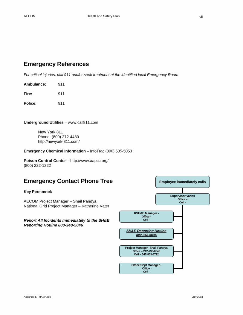
AECOM Health and Safety Plan
Appendix E - HASP.doc July 2018
viii
Emergency References For critical injuries, dial 911 and/or seek treatment at the identified local Emergency Room
Ambulance: 911
Fire: 911
Police: 911
Underground Utilities – www.call811.com
New York 811 Phone: (800) 272-4480 http://newyork-811.com/
Emergency Chemical Information – InfoTrac (800) 535-5053
Poison Control Center – http://www.aapcc.org/ (800) 222-1222
Emergency Contact Phone Tree Key Personnel:
AECOM Project Manager – Shail Pandya National Grid Project Manager – Katherine Vater
Report All Incidents Immediately to the SH&E Reporting Hotline 800-348-5046
Employee immediately calls
Supervisor-varies Office –
Cell -
RSH&E Manager -
Office - Cell -
Office/Dept Manager - Office -
Cell -
Project Manager- Shail Pandya Office – 212-798-8548 Cell – 347-803-8722
SH&E Reporting Hotline 800-348-5046
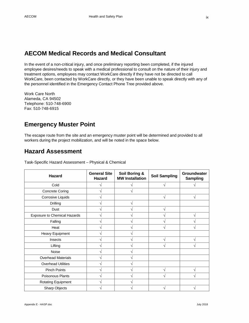
AECOM Health and Safety Plan
Appendix E - HASP.doc July 2018
ix
AECOM Medical Records and Medical Consultant In the event of a non-critical injury, and once preliminary reporting been completed, if the injured employee desires/needs to speak with a medical professional to consult on the nature of their injury and treatment options, employees may contact WorkCare directly if they have not be directed to call WorkCare, been contacted by WorkCare directly, or they have been unable to speak directly with any of the personnel identified in the Emergency Contact Phone Tree provided above.
Work Care North Alameda, CA 94502 Telephone: 510-748-6900 Fax: 510-748-6915
Emergency Muster Point The escape route from the site and an emergency muster point will be determined and provided to all workers during the project mobilization, and will be noted in the space below.
Hazard Assessment Task-Specific Hazard Assessment – Physical & Chemical
Hazard General Site Hazard
Soil Boring & MW Installation Soil Sampling Groundwater
Sampling Cold √ √ √ √
Concrete Coring √ √ Corrosive Liquids √ √ √
Drilling √ √ Dust √ √ √
Exposure to Chemical Hazards √ √ √ √ Falling √ √ √ √ Heat √ √ √ √
Heavy Equipment √ √ Insects √ √ √ √ Lifting √ √ √ √ Noise √ √
Overhead Materials √ √ Overhead Utilities √ √
Pinch Points √ √ √ √ Poisonous Plants √ √ √ √
Rotating Equipment √ √ Sharp Objects √ √ √ √
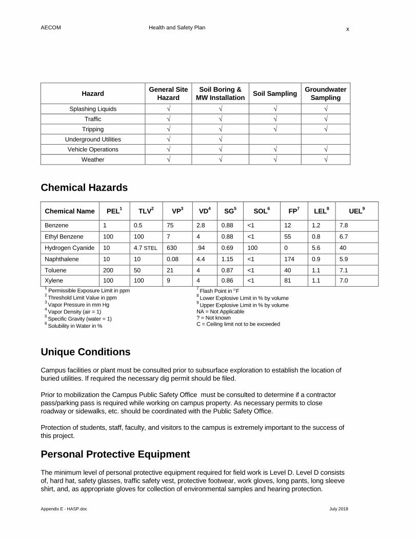
AECOM Health and Safety Plan
Appendix E - HASP.doc July 2018
x
Hazard General Site Hazard
Soil Boring & MW Installation Soil Sampling Groundwater
Sampling Splashing Liquids √ √ √ √
Traffic √ √ √ √ Tripping √ √ √ √
Underground Utilities √ √ Vehicle Operations √ √ √ √
Weather √ √ √ √
Chemical Hazards
Chemical Name PEL1 TLV2 VP3 VD4 SG5 SOL6 FP7 LEL8 UEL9
Benzene 1 0.5 75 2.8 0.88 <1 12 1.2 7.8
Ethyl Benzene 100 100 7 4 0.88 <1 55 0.8 6.7
Hydrogen Cyanide 10 4.7 STEL 630 .94 0.69 100 0 5.6 40
Naphthalene 10 10 0.08 4.4 1.15 <1 174 0.9 5.9
Toluene 200 50 21 4 0.87 <1 40 1.1 7.1 Xylene 100 100 9 4 0.86 <1 81 1.1 7.0 1 Permissible Exposure Limit in ppm 2 Threshold Limit Value in ppm 3 Vapor Pressure in mm Hg 4 Vapor Density (air = 1) 5 Specific Gravity (water = 1) 6 Solubility in Water in %
7 Flash Point in °F 8 Lower Explosive Limit in % by volume 9 Upper Explosive Limit in % by volume NA = Not Applicable ? = Not known C = Ceiling limit not to be exceeded
Unique Conditions Campus facilities or plant must be consulted prior to subsurface exploration to establish the location of buried utilities. If required the necessary dig permit should be filed.
Prior to mobilization the Campus Public Safety Office must be consulted to determine if a contractor pass/parking pass is required while working on campus property. As necessary permits to close roadway or sidewalks, etc. should be coordinated with the Public Safety Office.
Protection of students, staff, faculty, and visitors to the campus is extremely important to the success of this project.
Personal Protective Equipment The minimum level of personal protective equipment required for field work is Level D. Level D consists of, hard hat, safety glasses, traffic safety vest, protective footwear, work gloves, long pants, long sleeve shirt, and, as appropriate gloves for collection of environmental samples and hearing protection.
AECOM Health and Safety Plan
Appendix E - HASP.doc July 2018
xi
Additional personal protective equipment such as chainsaw chaps and sleeves, mesh face shield will be required for the cleaning and grubbing task.
Air Monitoring Instruments Air monitoring in the breathing zone of field personnel potentially exposure to contaminated soils and groundwater will be conducted using a Photoionization detector (PID) with a 10.62 eV lamp.
Respiratory Protection If conditions warrant, Level C respirator protection in the form of half face or full face air purifying respirator with a combination organic vapors cartridge with P 100 filters will be required.

AECOM Health and Safety Plan
Appendix E – Jamaica MGP HASP July 2018
1-1
1.0 Introduction
1.1 AECOM Environment Safety Policy
AECOM Environment (AECOM) is committed to providing our employees with a safe and healthy work environment. It is not only our obligation to each other, but also a sound business practice to do so. Work related injuries and illnesses cause needless pain and suffering, cost money, and adversely affect our reputation with our clients. It is our firm belief that all work related injuries and illnesses are preventable, and it is therefore our goal to have a workplace that is free from occupational injuries and illnesses. Every attempt shall be made to eliminate the possibility of injuries and illnesses. No aspect of the company's activities, including expediency and cost, shall take precedence over the health and safety of our employees.
1.1.1 Maximum Duration of the Work Day for Field Activities
An employee may not work a shift that exceeds 16 hours in duration. For the purpose of this policy, the work shift includes time spent at lunch on break, and driving to and from the site. If an employee works more than one shift during the course of a calendar day, the total number of hours worked in that day cannot exceed 16 hours. If work is to be done continuously in ambient air temperatures of less than 20oF, the Site Safety Officer and Field Manager will use a guideline of limiting work shifts to 10 hours in duration, including 8 hours working outdoors and 2 hours of time spent at lunch, breaks, and travel. Refer to Section 5.15, Cold Stress, for further work day guidelines.
1.1.2 Short Service Employee
A Short Service Employee (SSE) is an employee with fewer than three months experience working supervised on field projects or an employee who has not completed required training or received required certifications.
Short Service Employees will not be assigned to this project unless they are supervised on site by a qualified person.
1.2 Health and Safety Plan (HASP)
1.2.1 HASP Purpose
The purpose of this HASP is to identify hazards associated with this project and specify engineering and administrative controls and personal protective equipment necessary to mitigate the risks associated with these hazards. This HASP addresses the hazards recognized prior to writing or updating the documents. As new hazards are encountered, a Job Hazard Assessment (JHA) or Job Safety Analysis (JSA) must be conducted and the results input into the HASP.
This HASP also assigns responsibilities for the implementation of safety programs on this project and defines monitoring and emergency response planning specific to the project.
1.2.2 HASP Applicability
This site-specific Health and Safety Plan (HASP) has been developed by AECOM. It establishes the health and safety procedures required to minimize potential risk to AECOM and contractor personnel involved with the Site Characterization work at the former Jamaica Holder Station Site located in
AECOM Health and Safety Plan
Appendix E – Jamaica MGP HASP July 2018
1-2
Queens, Queens County, New York. AECOM is conducting this work on behalf of National Grid USA (National Grid).
The provisions of this plan apply to AECOM personnel who could potentially be exposed to safety and/or health hazards related to activities described in Section 3.0 of this document.
Client, Subcontractor employees, and third party personnel performing work that potentially exposes them to the chemical and physical hazards at the site are recommended to work under their own HASP and are also expected to review and acknowledge this HASP as a recognition of the SH&E standards that AECOM expects outside personnel to uphold.
This HASP has been written to comply with the requirements of the Occupational Safety and Health Administration (OSHA) Personal Protective Equipment Standard (29 CFR 1910.132) for all activities and the OSHA Hazardous Waste Operations and Emergency Response Standard (29 CFR 1910.120) for tasks where there are potential exposures to subsurface contaminants. All activities covered by this HASP must be conducted in complete compliance with this HASP and with all applicable federal, state, and local health and safety regulations. Personnel covered by this HASP who cannot or will not comply will be excluded from site activities.
This plan will be distributed to each employee involved with the proposed activities at the site, including subcontractor employees. Each employee must sign a copy of the attached health and safety plan sign-off sheet (see Attachment A).
This HASP only pertains to the tasks that are listed in Section 3.0. A task specific HASP or addendum to this HASP will be developed at a later date for any other subsequent investigative/remedial activities at the site.
1.3 Organization/Responsibility
The implementation of health and safety at this project location will be the shared responsibility of the AECOM Project Manager (PM), the AECOM Regional Safety, Health & Environment Manager (RSM), the AECOM Project Site Safety Officer (SSO) and other AECOM personnel and AECOM’s contractors implementing the proposed scope of work.
1.3.1 AECOM Project Manager
The AECOM PM is the individual who has the primary responsibility for ensuring the overall health and safety of this project. As such, the PM is responsible for ensuring that the requirements of this HASP are implemented. Some of the PM's specific responsibilities include:
• Assuring that all personnel to whom this HASP applies, including AECOM subcontractors, have received a copy of it;
• Providing the RSM with updated information regarding conditions at the site and the scope of site work;
• Providing adequate authority and resources to the on-site SSO to allow for the successful implementation of all necessary safety procedures;
• Supporting the decisions made by the SSO and RSM;
• Maintaining regular communications with the SSO and, if necessary, the RSM;

AECOM Health and Safety Plan
Appendix E – Jamaica MGP HASP July 2018
1-3
• Coordinating the activities of all AECOM subcontractors and ensuring that they are aware of the pertinent health and safety requirements for this project,
• In the event that an incident occurs, leading the incident investigation to identify root causes, corrective actions and lessons learned; and
• Conducting random project audits.
1.3.2 AECOM Regional Safety, Health & Environment Manager
The AECOM RSM is the individual responsible for the preparation, interpretation and modification of this HASP. Modifications to this HASP which might result in less stringent precautions cannot be undertaken by the PM or the SSO without the approval of the RSM. Specific duties of the RSM include:
• Writing, approving and amending the HASP for this project;
• Advising the PM and SSO on matters relating to health and safety on this site;
• Recommending appropriate personal protective equipment (PPE) and respiratory equipment to protect personnel from potential site hazards;
• Assisting with Incident investigations; and,
• Maintaining regular contact with the PM and SSO to evaluate site conditions and new information which might require modifications to the HASP; and
• Conducting random project audits.
1.3.3 AECOM Site Safety Officer
All AECOM field technicians are responsible for implementing the safety requirements specified in this HASP. However, one field technician will serve as the SSO. The SSO will be appointed by the PM. The SSO will be on-site during all activities covered by this HASP. The SSO is responsible for enforcing the requirements of this HASP once work begins. The SSO has the authority to immediately correct all situations where noncompliance with this HASP is noted and to immediately stop work in cases where an immediate danger is perceived. Some of the SSO's specific responsibilities include:
• Assuring that all personnel to whom this HASP applies, including all subcontractors, have reviewed this HASP, and submitted a completed copy of the HASP review and acceptance form (Attachment A);
• Assuring that all personnel to whom this HASP applies have attended a pre-entry briefing and any subsequent safety meetings that are conducted during the implementation of the program;
• Maintaining a high level of health and safety consciousness among employees implementing the proposed investigative activities;
• Securing Work Permits. The SSO must determine what, if any, work permits must be secured from the facility prior to the commencement of activities. If required, the SSO must determine how long the work permit is good for and verify that all the provisions of the work permit can be met by AECOM and its subcontractors.
• Procuring the air monitoring instrumentation required and performing air monitoring for investigative activities;
• Procuring and distributing the PPE and safety equipment needed for this project for AECOM employees;
AECOM Health and Safety Plan
Appendix E – Jamaica MGP HASP July 2018
1-4
• Verifying that all PPE and health and safety equipment used by AECOM is in good working order;
• Verifying that AECOM contractors are prepared with the PPE, respiratory protection and safety equipment required for this program;
• Preparing an initial Job Safety Analysis (JSA) during the initial mobilization and revising the Job Safety Analysis if conditions or tasks change and communicating with all workers the results of the Job Safety Analysis. See attachment B for a JSA form. The JSA will be reviewed daily by all workers and updated as needed.
• Notifying the PM of all noncompliance situations and stopping work in the event that an immediate danger situation is perceived;
• Monitoring and controlling the safety performance of all personnel within the established restricted areas to ensure that required safety and health procedures are being followed;
• Conducting accident/incident investigations and preparing accident/incident investigation reports;
• Conducting the pre-entry briefing prior to beginning work and subsequent safety meetings as necessary; and
• Initiating emergency response procedures in accordance with Section 11.0 of this HASP.
1.3.4 AECOM Field Personnel
All AECOM field personnel covered by this HASP are responsible for following the health and safety procedures specified in this HASP and for performing their work in a safe and responsible manner. Some of the specific responsibilities of the field personnel are as follows:
• Assess each task prior to beginning work on that task for hazards and necessary precautions.
• Assess the work area for changing conditions and new hazards and address the hazards;
• Stop work and initiate corrective actions if work site hazards create unacceptable risk;
• Reading this HASP in its entirety prior to the start of on-site work;
• Submitting a completed HASP Review and acceptance form (Attachment A)to the AECOM SSO prior to the start of work;
• Attending the required pre-entry briefing prior to beginning on-site work and any subsequent safety meetings that are conducted during the implementation of the program;
• Bringing forth any questions or concerns regarding the content of the HASP to the PM or the SSO prior to the start of work;
• Reporting all Incidents, injuries and illnesses, regardless of their severity, to the AECOM SSO; and,
• Complying with the requirements of this HASP and the requests of the SSO.
1.3.5 Contractors
Additionally, contractors hired by AECOM are responsible for:
• Reading the HASP in its entirety prior to the start of on-site work;

AECOM Health and Safety Plan
Appendix E – Jamaica MGP HASP July 2018
1-5
• Attending the required pre-entry briefing prior to beginning on-site work and any subsequent safety meetings that are conducted during the implementation of the program;
• Ensuring that their equipment is in good working order via daily inspections;
• Operating their equipment in a safe manner;
• Appointing an on-site safety coordinator to interface with the AECOM SSO;
• Providing AECOM with copies of material safety data sheets (MSDS) for all hazardous materials brought on-site; and,
• Providing all the required PPE, respiratory equipment and safety supplies to their employees.
1.4 SH&E Expectations
Commitment to safety, health, and environmental excellence requires that all work proceed only after it is safe and environmentally sound to do so. The responsibility for ensuring that this takes place rests with every worker present at this property. Effectively meeting these responsibilities depends upon open communication between individuals and their supervisors prior to work beginning, and – in certain cases – after safety, health and/or environmental issues are identified. Completing a Job Safety Analysis (JSA) to aid in planning safe work performance will be an integral part of meeting safety, health and environment (SHE) expectations.
The safety and health of on site personnel will take precedence over cost and schedule considerations for all project work. All AECOM personnel have the authority to STOP WORK if they see a potential or actual hazard that may threaten the safety of people or the environment. Upon stopping work, the SSO must be immediately notified and provided with information regarding the nature of the safety, health or environmental concern. The SSO should meet with the worker with the intent of resolving the worker’s concerns. Once the concerns are resolved to the satisfaction of the worker, work can proceed.
If the concerns are not resolved to the satisfaction of the worker and/or the SSO, work does not proceed. The AECOM RSM will be contacted to obtain assistance in resolving the concerns. Using his/her expertise, safety, health, and environmental rules, regulations, and procedures, the AECOM RSM will attempt to resolve the matter with all parties involved. Work will not resume until this criterion is met.
1.5 Management of Change/Modification of the HASP
1.5.1 Management of Change
This document discusses the physical hazards associated with the proposed activities. However, unanticipated site-specific conditions or situations might occur during the implementation of this project. Also, AECOM and/or the contractors may elect to perform certain tasks in a manner that is different from what was originally intended due to a change in field conditions. As such, this HASP must be considered a working document that is subject to change to meet the needs of this dynamic project.
1.5.2 HASP Modification
Should significant information become available regarding potential on-site hazards, it will be necessary to modify this HASP. All proposed modifications to this HASP must be reviewed and approved by the AECOM RSM before such modifications are implemented. Any significant modifications must be incorporated into the written document as addenda and the HASP must be reissued. The AECOM PM will ensure that all personnel covered by this HASP receive copies of all issued addenda. Sign-off forms will accompany each addendum and must be signed by all personnel covered by the addendum. Sign-

AECOM Health and Safety Plan
Appendix E – Jamaica MGP HASP July 2018
1-6
off forms will be submitted to the AECOM PM. The HASP addenda should be distributed during the daily safety meeting so that they can be reviewed and discussed. Attendance forms will be collected during the meeting.
1.5.3 Job Safety Analysis (JSA)
AECOM and/or AECOM’s contractors will prepare a Job Safety Analysis (JSA) for each task to be performed prior to commencing work. The use of new techniques will be reviewed and if new hazards are associated with the proposed changes, they will be documented and evaluated on the JSA form. An effective control measure must also be identified for each new hazard. JSA forms will be reviewed by the SSO prior to being implemented. Once approved, the completed forms will be reviewed with all field staff during the daily safety meeting. A blank JSA form is presented as Attachment B.
1.5.4 Employees Working Alone
Employees working alone at project sites will review the JSA for their tasks as they are conducting their daily overview and reconnaissance of the site. After completing the JSA review/revision and site reconnaissance, the employee should call the Project Manager and report any new hazards or site conditions observed.
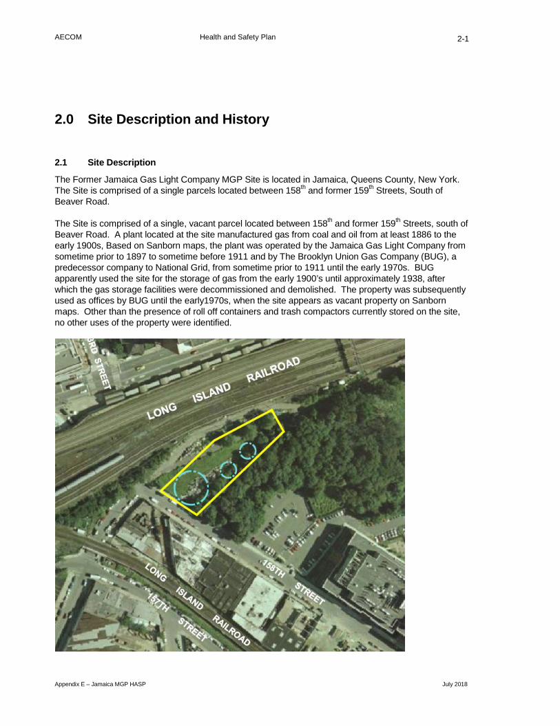
AECOM Health and Safety Plan
Appendix E – Jamaica MGP HASP July 2018
2-1
2.0 Site Description and History
2.1 Site Description
The Former Jamaica Gas Light Company MGP Site is located in Jamaica, Queens County, New York. The Site is comprised of a single parcels located between 158th and former 159th Streets, South of Beaver Road.
The Site is comprised of a single, vacant parcel located between 158th and former 159th Streets, south of Beaver Road. A plant located at the site manufactured gas from coal and oil from at least 1886 to the early 1900s, Based on Sanborn maps, the plant was operated by the Jamaica Gas Light Company from sometime prior to 1897 to sometime before 1911 and by The Brooklyn Union Gas Company (BUG), a predecessor company to National Grid, from sometime prior to 1911 until the early 1970s. BUG apparently used the site for the storage of gas from the early 1900’s until approximately 1938, after which the gas storage facilities were decommissioned and demolished. The property was subsequently used as offices by BUG until the early1970s, when the site appears as vacant property on Sanborn maps. Other than the presence of roll off containers and trash compactors currently stored on the site, no other uses of the property were identified.

AECOM Health and Safety Plan
Appendix E – Jamaica MGP HASP July 2018
2-2
2.2 Site History
A review of the history of the Former Jamaica Gas Light Company MGP Site has been developed based on a review of the historic Sanborn Fire Insurance maps, aerial photographs for the Site as well as historic investigation reports.
Sanborn maps were available from 1886, 1891, 1897, 1901, 1911, 1925, 1942, 1951, 1963, 1967, 1981, 1982, 1985 through 1988, 1990 through 1993, 1995, 1996, 1999, and 2001 through 2006. Aerial photos were available for 1954, 1966, 1975, 1984, 1985, and 1994.
The operator of the site is not identified until 1897, when historic documentation state the Jamaica Gas Light Company as the operator sometime prior to 1897 to sometime before 1911 and BUG, from sometime prior to 1911 to the early 1970s. The Site operated in the manufacturing of gas from coal and oil from the at least 1886 to the early 1900s when it apparently was used for the storage of gas until around 1942`. The property was subsequently used for office space by BUG as offices until the early1970s when the site appears as vacant property.
2.3 Potential Contaminants of Concern
Potential contaminants of concern in soil include:
• VOCs, primarily BTEX
• SVOCs, primarily naphthalene and low molecular weight PAHs
• Total petroleum hydrocarbons
• Metals, primarily arsenic, lead, and mercury
• Cyanide
• Possibly pesticides and herbicides
• Possibly PCBs
Contaminants of concern in groundwater are as of yet unknown, as no groundwater samples have been collected or analyzed at this site. The contaminants of concern that could reasonably be expected to be present in groundwater are the same as those listed above.

AECOM Health and Safety Plan
Appendix E – Jamaica MGP HASP July 2018
3-1
3.0 Chemical Hazard Assessment and Control
3.1 Chemical hazards
Typical products associated with former gas holders could include volatile organic compounds (VOCs) such as benzene, toluene, ethylbenzene and xylenes (BTEX), polycyclic aromatic hydrocarbons (PAHs), tar-like materials, and certain trace metals (arsenic, cyanide, lead) and possible PCBs from compressor oil.
3.1.1 Volatile Organic Compounds
The VOCs associated with potential MGP wastes include BTEX. Exposure to the vapors of BTEX above their respective OSHA permissible exposure limits (PELs) may produce irritation of the mucous membranes of the upper respiratory tract, nose and mouth. Overexposure may also result in the depression of the central nervous system (CNS). Symptoms of such exposure include drowsiness, headache, fatigue and drunken-like behaviors. Prolonged overexposure to benzene vapors has detrimental effects on the blood-forming system ranging from anemia to leukemia. The PEL for benzene is 1 part per million (ppm) as an 8 hour time-weighted average (TWA). The American Conference of Governmental Industrial Hygienists (ACGIH) recommends a threshold limit value (TLV) of 0.5 ppm. The OSHA PEL for ethylbenzene is 100 ppm. The PEL for toluene is 200 ppm. However, the ACGIH recommends a TLV of 50 ppm for toluene. Xylene is a flammable, colorless liquid with an OSHA PEL of 100 ppm as an 8-hour TWA. Inhalation of xylene vapors above the PEL may result in motor activity changes, irritability and drunken-like behaviors. Xylene vapors are also irritating to the eye.
3.1.2 Polycyclic Aromatic Hydrocarbons
Typical coal gasification byproducts (coal tar) are referred to as PAH compounds. PAH compounds are a family of multiple ring aromatic compounds commonly found in fossil fuels and formed from the incomplete combustion of organic materials. Repeated contact with PAH compounds may cause photosensitization of the skin, producing skin burns after subsequent exposure to ultra-violet light. Certain PAHs as a group are considered potential human carcinogens (CaPAH). OSHA regulates PAHs as coal tar pitch volatiles (CTPV) and has established a PEL for CTPV of 0.2 mg/m3, as an 8-hr TWA.
Of the PAH compounds typically present at MGP sites, naphthalene is typically present at higher concentrations than the other compounds. Naphthalene is easily detected due to its characteristic moth-ball like odor. The inhalation of high concentrations of naphthalene vapor may result in nausea, vomiting, abdominal pain and irritation of the bladder. Prolonged overexposure may result in renal shut down. The OSHA PEL for naphthalene, as an 8-hr TWA, is 10 ppm.
3.1.3 Polychlorinated Biphenyls
PCBs are a series of technical mixtures consisting of many isomers and compounds that vary from mobile oily liquids to white crystalline solids to hard non-crystalline resins. PCB oils are typically used in heat transfer applications, hydraulic fluids and lubricants. Technical products vary in composition and in the degree of chlorination. PCBs are generally considered to be of moderate to low toxicity. The higher the chlorine content of the PCBs, the greater the toxicity is likely to be. Dermal contact with liquid PCBs may produce skin irritation or a rash. Prolonged or repeated skin contact may cause dermatitis or "chloracne." Studies suggest that chronic exposure to high concentrations of PCBs can cause liver damage. The OSHA permissible exposure limit (PEL) for PCBs with 54% chlorine content is 0.5 mg/m3, as an 8-hr time-weighted average (TWA).

AECOM Health and Safety Plan
Appendix E – Jamaica MGP HASP July 2018
3-2
3.1.4 Inorganic Compounds
Lead and other metals found in and around former gas holders could have originated from paint chips and dust from historic holder painting operations or demolition of the holder. In general, the inhalation of metal dusts is irritating to the upper respiratory tract and nasal mucous membranes. Most metal dusts may cause dermatitis and/or eye irritation.
The early symptoms of lead poisoning, as a result of overexposure (either through ingestion or inhalation) include fatigue, sleep disturbance, headache, aching bones and muscles, digestive irregularities, abdominal pains, and decreased appetite. Chronic overexposures to lead affect the CNS and male and female reproductive systems. Lead has also been identified as a fetotoxin. The OSHA PEL for inorganic lead is 50 micrograms per cubic meter (ug/m3).
Arsenic is a naturally occurring element widely distributed in the earth's crust. Breathing high levels of inorganic arsenic can give you a sore throat or irritated lungs. Ingesting high levels of inorganic arsenic can result in death. Lower levels of arsenic can cause nausea and vomiting, decreased production of red and white blood cells, abnormal heart rhythm, damage to blood vessels, and a sensation of "pins and needles" in hands and feet. Ingesting or breathing low levels of inorganic arsenic for a long time can cause a darkening of the skin and the appearance of small "corns" or "warts" on the palms, soles, and torso. Skin contact with inorganic arsenic may cause redness and swelling.
Organic arsenic compounds are less toxic than inorganic arsenic compounds. Exposure to high levels of some organic arsenic compounds may cause similar effects as inorganic arsenic. The Occupational Safety and Health Administration has set limits of 10 microgram arsenic per cubic meter of workplace air (10 µg/m³) for 8 hour shifts and 40 hour work weeks.
Associated with former MGP sites and gas holders is ferro/ferri cyanide (Prussian Blue). Blue staining is the characteristic associated with the presence of oxide box wastes (ferrocyanide). Therefore, the presence of this material is very easily identified during field investigations. The cyanides associated with oxide box wastes are present in a form that is generally unavailable or complexed with metals such as iron, which makes the cyanide more stable. Thus, the reported effects of free cyanide are not applicable. OSHA has not established a PEL for ferro/ferri cyanide compounds. Similarly, the ACGIH has not recommended a TLV for these compounds
The release of hydrogen cyanide to air at MGP sites is theoretically possible if the pH of the soil or groundwater is low, but because such releases would occur from very slow dissociation of iron cyanides followed by rapid volatilization and dissipation, this is unlikely to be an exposure issue. Nevertheless, hydrogen cyanide and the common salts of cyanide will penetrate intact skin. All skin surfaces that could come in contact with contaminated water or soil must be protected.
Cyanide when inhaled, ingested or absorbed through skin reacts with the muscle cells preventing them from using oxygen in the blood. The result is that the muscles cease to function and the oxygen level in the blood reaches saturation. The saturated blood causes the victim to become flushed and the lips and fingernails become very red. CPR is not affective on victims of cyanide poisoning. Get medical attention immediately if cyanide poisoning is suspected.
3.1.5 Dust
Dust generated during coring or cutting of concrete, boring, or excavations can be hazardous to the respiratory system and irritating to the eyes. Dust can also carry the contaminants of concern potentially exposing workers by skin contact and inhalation. The ACGIH has established an eight-hour exposure limit for dust at 3 mg/M3. The concentrations of the chemicals of concern in the soil are low enough that
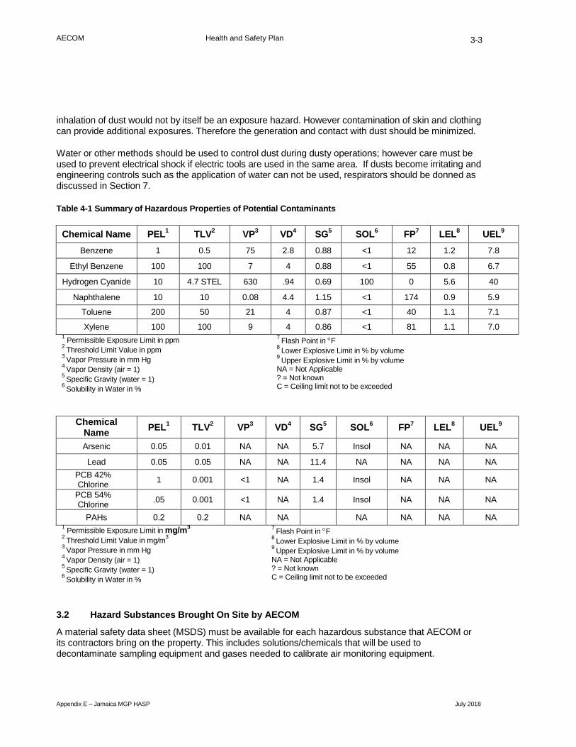
AECOM Health and Safety Plan
Appendix E – Jamaica MGP HASP July 2018
3-3
inhalation of dust would not by itself be an exposure hazard. However contamination of skin and clothing can provide additional exposures. Therefore the generation and contact with dust should be minimized.
Water or other methods should be used to control dust during dusty operations; however care must be used to prevent electrical shock if electric tools are used in the same area. If dusts become irritating and engineering controls such as the application of water can not be used, respirators should be donned as discussed in Section 7.
Table 4-1 Summary of Hazardous Properties of Potential Contaminants
Chemical Name PEL1 TLV2 VP3 VD4 SG5 SOL6 FP7 LEL8 UEL9 Benzene 1 0.5 75 2.8 0.88 <1 12 1.2 7.8
Ethyl Benzene 100 100 7 4 0.88 <1 55 0.8 6.7
Hydrogen Cyanide 10 4.7 STEL 630 .94 0.69 100 0 5.6 40
Naphthalene 10 10 0.08 4.4 1.15 <1 174 0.9 5.9
Toluene 200 50 21 4 0.87 <1 40 1.1 7.1
Xylene 100 100 9 4 0.86 <1 81 1.1 7.0 1 Permissible Exposure Limit in ppm 2 Threshold Limit Value in ppm 3 Vapor Pressure in mm Hg 4 Vapor Density (air = 1) 5 Specific Gravity (water = 1) 6 Solubility in Water in %
7 Flash Point in °F 8 Lower Explosive Limit in % by volume 9 Upper Explosive Limit in % by volume NA = Not Applicable ? = Not known C = Ceiling limit not to be exceeded
Chemical Name PEL1 TLV2 VP3 VD4 SG5 SOL6 FP7 LEL8 UEL9
Arsenic 0.05 0.01 NA NA 5.7 Insol NA NA NA
Lead 0.05 0.05 NA NA 11.4 NA NA NA NA PCB 42% Chlorine 1 0.001 <1 NA 1.4 Insol NA NA NA
PCB 54% Chlorine .05 0.001 <1 NA 1.4 Insol NA NA NA
PAHs 0.2 0.2 NA NA NA NA NA NA 1 Permissible Exposure Limit in mg/m3 2 Threshold Limit Value in mg/m3 3 Vapor Pressure in mm Hg 4 Vapor Density (air = 1) 5 Specific Gravity (water = 1) 6 Solubility in Water in %
7 Flash Point in °F 8 Lower Explosive Limit in % by volume 9 Upper Explosive Limit in % by volume NA = Not Applicable ? = Not known C = Ceiling limit not to be exceeded
3.2 Hazard Substances Brought On Site by AECOM
A material safety data sheet (MSDS) must be available for each hazardous substance that AECOM or its contractors bring on the property. This includes solutions/chemicals that will be used to decontaminate sampling equipment and gases needed to calibrate air monitoring equipment.

AECOM Health and Safety Plan
Appendix E – Jamaica MGP HASP July 2018
3-4
In addition, all containers of hazardous materials must be labeled in accordance with OSHA's Hazard Communication Standard. Either the original manufacturer’s label or an NFPA 704M label specific for the material (as shown at the right) is considered to be an acceptable label.
3.3 Chemical Exposure and Control
3.3.1 Chemical Exposure Potential
Employees can be exposed by inhalation to the chemicals of concern during the installation of the soil borings and sampling activities. Another route of potential exposure to the contaminants of concern is via direct dermal contact with soils and groundwater during sampling.
Although highly unlikely, exposure to all of the contaminants of concern can occur via ingestion (hand-to-mouth transfer). The decontamination procedures described in Section 9.0 address personal hygiene issues that will limit the potential for contaminant ingestion.
3.3.2 Chemical Hazard Control
The chemical hazards associated with the investigative and sampling activities can be controlled in several ways, including:
AECOM will perform air monitoring (Section 6) in the worker's breathing zone to determine exposure to the chemicals of concern during the installation of soil borings and the sampling program. If exposures exceed the action levels, respiratory protection as discussed in Section 7, will be donned.
To avoid direct dermal contact with contaminated media, protective clothing, as described in Section 7 will be required when collecting samples and decontaminating sampling equipment.
3.4 Hazardous Waste Management
Waste generated as a result of investigation activities will be containerized local to the point of generation, sampled for characterization purposes and secured prior to off-site transportation and disposal. Upon receipt of analytical results, the AECOM project team will work with the Client to properly characterize, profile and dispose of the waste(s).

AECOM Health and Safety Plan
Appendix E – Jamaica MGP HASP July 2018
4-1
4.0 Physical Hazards and Controls
4.1 Back Safety
Using the proper techniques to lift and move heavy pieces of equipment is important to reduce the potential for back injury. The following precautions should be implemented when lifting or moving heavy objects:
• Bend at the knees, not the waist. Let your legs do the lifting;
• Do not twist while lifting;
• Bring the load as close to you as possible before lifting;
• Be sure the path you are taking while carrying a heavy object is free of obstructions and slip, trip and fall hazards;
• Use mechanical devices to move objects that are too heavy to be moved manually (35 lbs and greater); and,
• If mechanical devices are not available, ask another person to assist you.
4.2 Concrete and Asphalt Coring & Cutting
Cutting and coring concrete and asphalt can involve numerous hazards. The noise generated as a result of the tools used, and adequate hearing protection is necessary when conditions outlined in the Noise section below are encountered. Tools used which can include drills and saws, must be appropriately guarded to prevent hands, PPE, and other objects from being caught-up in the moving parts and drawing employees in. Dust may also be generated while cutting concrete and either respiratory protection or dust suppression will need to be utilized to prevent exposure. Additional consideration must be given chemical hazard concerns that may exist in the materials underlying the concrete.
4.3 Corrosive Liquids
Site activities may require the use of corrosive liquids for preserving samples once collected, identifying substances in the field, or as part of system operations and maintenance. When corrosive liquids are identified in the work area, PPE upgrades will need to include an appropriate glove to mitigate the hazard, protective eye wear to guard against splashing liquids, and the potential need for poly-coated Tyvek to be worn. Additionally, the job task will be analyzed to determine if splashing and spilling can be minimized through the use of special equipment or procedures. Examples include using a funnel, identifying an alternative substance for use, and more.
4.4 Drilling Hazards
Use of a drill rig to advance soil borings and install monitoring wells will require all personnel in the vicinity of the operating rig to wear steel-toed boots, hard hats, hearing protection and safety eyewear. Personnel shall not remain in the vicinity of operating equipment unless it is required for their work responsibilities.
Additionally, the following safety requirements must be adhered to:
AECOM Health and Safety Plan
Appendix E – Jamaica MGP HASP July 2018
4-2
• All drill rigs and other machinery with exposed moving parts must be equipped with an operational emergency stop device. Drillers and geologists must be aware of the location of this device. This device must be tested prior to job initiation and periodically thereafter.
• The driller must never leave the controls while the tools are rotating unless all personnel are kept clear of rotating equipment.
• A long-handled shovel or equivalent must be used to clear drill cuttings away from the hole and from rotating tools. Hands and/or feet are not to be used for this purpose.
• A remote sampling device must be used to sample drill cuttings if the tools are rotating or if the tools are readily capable of rotating. Samplers must not reach into or near the rotating equipment. If personnel must work near any tools, which could rotate, the driller must shut down the rig prior to initiating such work.
• Driller’s Drillers, helpers and geologists must secure all loose clothing, long hair, or jewelry when in the vicinity of drilling operations.
• Only equipment, that has been approved by the manufacturer, may be used in conjunction with drilling equipment Pins that protrude excessively from augers shall not be allowed
• No person shall climb the drill mast while tools are rotating.
• No person shall climb beyond 6 feet above ground on the drill mast without the use of ANSI-approved fall protection (approved belts, lanyards and a fall protection slide rail) or portable ladder that meets the requirements of OSHA standards.
• When using the rig’s hoist to lift or move objects other than the equipment associated with the direct push operation, an assessment of the force required to perform the lift and the rig’s design specifications must be made to determine whether the lift can be made safely. In all cases personnel must not be in line with the cable when it is under tension.
• If drilling operations are to be performed within an enclosed space proper procedures must be followed to prevent the accumulation of carbon monoxide within the work area.
• Open doors and windows and provide ventilation to the outside.
• Employ the use of a mechanical ventilation system, i.e. blower or fan, appropriately sized for the room to circulate fresh air.
• Connect equipment exhaust points to hoses that can be direct ventilated to an outside area.
4.4.1 Rotary Auger & Rotating Parts
Exposure to rotating parts can occur when working near the drilling rig or the internal combustion engine. All rotating parts should be covered with guards to prevent access by workers. When performing maintenance activities that require the rotating parts to be exposed, workers should not allow loose clothing, hands, or tools to approach the rotating parts. Guards must be replaced as soon as possible after completing the maintenance task.
Operation of drilling equipment also creates hazards associated with pinch points and rotating equipment. Employees will evaluate work procedures to avoid placing their body and extremities in the path of rotating equipment and tools to avoid being struck by moving equipment, tools and machinery. Similarly, these hazards also create pinch point hazards where the body and extremities, especially the hands, can be caught in moving equipment and crushed. Employees will evaluate equipment and tool use procedures to identify pinch points and develop procedures to avoid placing body parts in a position where they can be caught in moving equipment, tools and machinery.

AECOM Health and Safety Plan
Appendix E – Jamaica MGP HASP July 2018
4-3
4.4.2 Direct Push Hazards
Use of the Direct Push System to advance soil borings and collect soil samples will require all personnel in the vicinity of the operating unit to wear steel-toed boots, hardhats, hearing protection and safety eyewear. Personnel shall not remain in the vicinity of operating equipment unless it is required for their work responsibilities. Additionally, the following safety requirements must be adhered to:
• A remote vehicle ignition is located on the control panel of the Geoprobe unit. This allows the operator to start and stop the vehicle engine from the rear. This device must be tested prior to job initiation and periodically thereafter. All employees should be aware of how to access and operate the rear ignition.
• The driller must never leave the controls while the probe is being driven.
• Drillers, helpers and geologists must secure all loose clothing when in the vicinity of drilling operations.
• The Geoprobe vehicle shall not be moved any distance with the probe in the extended position. Check for clearance at roof or the vehicle before folding the Geoprobe out of the carrier vehicle.
• Be sure the parking brake is set, or vehicle wheels have been chocked, before probing.
• Never allow the derrick foot to be lifted more than 6" off of the ground surface.
• Deactivate hydraulics when adding or removing probe rods, anvils or any tool in the hammer.
• Verify that all threaded parts are completely threaded together before probing.
4.4.2.1 Cuts and Lacerations
Geoprobe soil samples are collected in acetate liners that must be cut open in order to collect the sample. Additionally, tubing will need to be cut to facilitate groundwater sampling. Additional tasks for the job may also pose laceration hazards. Tube-cutters are available and should be used to eliminate this hazard. However, if it is necessary to use knives or blades, follow the safety precautions listed below:
• Keep your free hand out of the way
• Secure the acetate liner so it won't roll or move while you are cutting
• Use only sharp blades; dull blades require more force which results in less knife control
• Pull the knife at an angle to your body; pulling motions are easier to manage
• Don't put your knife in your pocket
• Use a hooked knife (i.e. linoleum knife) or a utility knife with a self-retracting blade
• Wear leather or Kevlar® gloves when using knives or blades.
4.4.3 Sonic Drilling
Use of a Sonic Drill Rig to advance soil borings, collect soil samples and/or install monitoring wells will require all personnel in the vicinity of the operating unit to wear steel-toed boots, hardhats, hearing protection and safety eyewear. Personnel shall not remain in the vicinity of operating equipment unless it is required for their work responsibilities. Additionally, the following safety requirements must be adhered to:

AECOM Health and Safety Plan
Appendix E – Jamaica MGP HASP July 2018
4-4
• A remote vehicle ignition may be located on the control panel of the Drill Rig. This allows the operator to start and stop the vehicle engine from the rear. This device must be tested prior to job initiation and periodically thereafter. All employees should be aware of how to access and operate the rear ignition.
• The driller must never leave the controls while the probe is being driven.
• Drillers, helpers and geologists must secure all loose clothing when in the vicinity of drilling operations.
• The Drill Rig shall not be moved any distance with the mast in the extended position. Check for clearance at roof or the vehicle before folding the Rig out of the carrier vehicle.
• Be sure the parking brake is set, vehicle wheels have been chocked and/or outrigger stabilizers have been positioned before drilling.
• Never allow the derrick foot to be lifted more than 6" off of the ground surface.
• Deactivate hydraulics when adding or removing rods, anvils or any tool in the hammer.
• Verify that all threaded parts are completely threaded together before drilling.
4.5 Noise Exposure
Use of a drill rig and excavation machinery may expose employees to excessive amounts of noise. Exposure to noise can result in the following:
• Temporary hearing losses where normal hearing returns after a rest period;
• Interference with speech communication and the perception of auditory signals;
• Interference with the performance of complicated tasks; and,
• Permanent hearing loss due to repeated exposure resulting in nerve destruction in the hearing organ.
During pre-clearing and drilling activities, a decibel meter will be used to measure noise levels in the work area. If noise levels equal or exceed 85 dBA, hearing protection must be worn. In the absence of an available decibel meter, hearing protection must be worn while performing activities requiring air compressors and drilling equipment. AECOM employees can wear either disposable earplugs and/or earmuffs but all hearing protection must have a minimum noise reduction rating (NRR) of 27 db.
4.6 Driving Safety
Drivers must be licensed to drive the class of vehicle they are operating and trained in defensive driving. Only AECOM personnel may drive AECOM vehicles or vehicles rented for AECOM business; client, subcontractor, or other work-related personnel may ride. Drivers and passengers must comply with all traffic laws and posted signs, and will not operate a vehicle if under the influence of impairing medication, alcohol, or any other substance.
Make sure that the following basic safe driving practices are followed at all times while working on this project:
• Always wear a seat belt while operating a motor vehicle or while traveling as a passenger.
• Obey speed limits and local traffic laws at all times.

AECOM Health and Safety Plan
Appendix E – Jamaica MGP HASP July 2018
4-5
• Obtain proper directions to the site in advance and take the route that is most likely to be free of known traffic hazards (e.g., congestion, construction, etc.) and that avoids travel through potentially dangerous neighborhoods.
• Abstain from distractions while driving (e.g., the use of cell phones, eating/drinking, reading maps, etc.) If necessary, stop the vehicle and pull over to perform such activities safely. AECOM policy is engine on, cell phone off. You must NOT operate a vehicle while talking on your cell phone, regardless of “hands free” or not. If you receive a call, pull over to answer it. DO NOT allow other distractions to interfere with your safe operation of the vehicle.
• Do not operate a motor vehicle if you are tired and/or have not had sufficient rest. AECOM’s H&S policy 1.2 limits the maximum length of the workday to 16 hours for fieldwork. This limit includes the time spent driving to/from a site.
• All unattended personnel transport vehicles will not be allowed to idle, and must be turned off when not in use.
4.6.1 Planning / Preparation
• Prior to departure, check traffic reports, weather conditions, road construction, and road closures. If necessary, develop an alternate route and new, approved JMP (Journey Management Plan).
• Prior to entering the vehicle, inspect the vehicle.
• Leave early to allow for contingencies.
4.6.2 Secure Packing
Do not move your vehicle unless all equipment and supplies are secured. Items and material which may roll, slide, or move about in your vehicle while traveling are a major hazard. Secure the load!
4.6.3 Emergency Procedures
Always move out of traffic if possible; even if those in front of you have stopped. Stopping on an active highway can precipitate being hit from the rear. If you must stop on an active roadway, leave at least one car length in front of you, and watch the rear mirror, so you can ease up if someone behind can’t stop. Keep your flashers on in this situation. If you are the only driver coming to a stop on an active roadway, leave the flashers on and when safe to do so, exit the car and get to a safe location.
If you must stop due to vehicle failure, etc. try to coast out of traffic. Put on your flashers, and tie a white handkerchief, etc. on the driver’s side door or mirror. If you remain in the vehicle, lock the doors. Use your cell phone to summon help.
4.7 Flying Objects Hazards
Activities involving the use of power tools, drilling rigs, and hand tools, among other activities, can create flying object hazards where objects can become projectiles. When flying objects represent projectiles employees need to use equipment that is appropriately guarded to minimize the creation of projectile hazards, and also use the appropriate PPE including hard hats, safety goggles, face shields to prevent projectiles from causing injuries to employees.

AECOM Health and Safety Plan
Appendix E – Jamaica MGP HASP July 2018
4-6
4.8 Hand Safety
4.8.1 Glove Selection
To protect onsite workers from hand injuries, the following gloves will be used for when performing a specific duty:
Brightly colored gloves will be used to help emphasize and easily locate the hands. It is recommended that the color of gloves be changed monthly to draw attention to the hands.
Pinch points are found between a moving object and a stationary object, or between two continuously moving objects. Yellow hand stickers will be placed on equipment to remind workers of pinch points.
4.8.2 Working with Glassware
Glass bottles, laboratory equipment, and VOA vials can break and cause lacerations and puncture wounds. The follow preventive measures should be taken to reduce the potential for broken glassware.
• Package all glassware such that there is no glass to glass contact during transportation or storage;
• Assume that any time glass strikes another object it is damaged;
• Inspect all glassware for cracks, scratches, and other damage before using;
• Lids and caps should be “finger tight” unless there is a torque specification and you use a torque wrench;
• Never fill a glass container (other than VOA vials with a septum) liquid full, always leave an air space to buffer thermal expansion of the liquid; and
• Avoid rapid temperature changes when filling glass containers.
Glass often has flaws that cannot be detected by visual inspection and the force needed to open and tighten lids can cause these flaws to fracture the glass. Any time force is applied to glass, workers should wear leather or preferably Kevlar® gloves. Kevlar® glove liners are available for use under Nitrile or cotton gloves.
4.8.3 Hand Tools
Rules for the safe use of hand tools:
• Select the right size tool for the job. Don’t use “cheaters” and avoid pulling old tools from the waste stream. There’s a reason why they were thrown away!
• All hand tools must be in safe condition.
• Handles must be sound, straight and tight-fitting.
• Always inspect tools before use and replace or repair worn or damaged tools.
• Always keep the cutting edges sharp and never test a cutting edge with your finger.
• When working on an elevated surface (ladder, truck, scaffold), ensure your tools are secure. Falling tools can cause serious injury.
• Always carry your tools correctly and never put sharp or pointed tools in your pocket.

AECOM Health and Safety Plan
Appendix E – Jamaica MGP HASP July 2018
4-7
• When carrying hand tools, always point the cutting edge to the ground.
• Always keep your tools in a dry place to prevent rust.
• Cutting tools must be kept sharp and properly shaped.
• Secure work pieces prior to cutting or drilling.
• Keep the unused hand and other people away from the tool.
4.8.4 Specific Tool Use
4.8.4.1 Screwdrivers
Most screwdrivers are not designed to be used on electrical equipment. Use an insulated screwdriver for electrical work.
Do not hold an object in the palm of one hand and press a screwdriver into it; place the object on a bench or table. Never hammer with a screwdriver. Never use a screwdriver with a broken handle, bent or burred blade, etc.
4.8.4.2 Pliers
Do not use pliers as a substitute for hammers, wrenches, pry bars, etc. Use insulated pliers when doing electrical work. Inspect the pliers frequently to make certain that they are free of breaks or cracks.
Use the right type of pliers for the specific task – adjustable, locking (Vise Grip®), standard, bolt size fit, pipe wrench.
4.8.4.3 Hammers
Use the correct hammer for the specific type of striking work (task) to be done. Always wear safety glasses when using a hammer to strike an object. Always use the claw portion of a hammer to remove nails and not as a pick or awl. Have an unobstructed view and swing when using a hammer. Watch for overhead interference on back and forward swing. Use a good grip and use something other then your hand to hold a nail when starting hammering. Check for defects on the handle and head before using. If the hammer head shows signs of mushrooming, replace it immediately.
Handles may be wood, tubular/solid steel or fiberglass. Replace any hammer with a loose handle before the head flies off and causes injury to you or someone else. Tighten loose handles with the proper wedges; never use nails or staples for wedges. If a steel or fiberglass handle is loose replace it, since it is more difficult to repair than a wooden one. Some fiberglass handles can be tightened with the aid of a repair kit with epoxy materials.
4.8.4.4 Wrenches
Select the correct size of wrench for the job. Never use a pipe wrench as a wrench handle extension. Too much leverage can ruin a tool and cause injury.
To avoid sudden slips, stand in a balanced position and always pull on the wrench instead of pushing against the fixed jaw, particularly when a pinch point is created. Wear gloves when using a wrench in a confined space.
Whenever possible use a box end wrench instead of an open end wrench to avoid slipping.

AECOM Health and Safety Plan
Appendix E – Jamaica MGP HASP July 2018
4-8
4.8.4.5 Chisels
Always wear safety goggles or a face shield when using a chisel. Drive chisels outward and away from your body. Do not use chisels to pry. Keep edges sharp for most effective work and protect when not in use. Driven tools (chisels, punches, etc.) must be dressed to remove any mushrooming. Use the proper hammer when using a chisel.
4.8.4.6 Knives
Always perform a thorough Job Safety Analysis (JSA) to define the proper cutting tool for the task.
Always place the item to be cut on a solid surface, attempt to hold the cut item without your hand and cut in a direction away from the body and hand.
Always keep hands and body clear of the knife stroke. Always keep the cutting tool blades sharp.
Make sure there is plenty of open space around you when using any cutting tool.
Use the following safer tools in replace of fixed open blade knives (FOBK) whenever possible:
• Self-retracting utility knives
• Guarded utility knives
• Shears, snips, and/or scissors
• Concealed blade cutters
• Pipe cutters
• Specialty cutters (e.g. Geoprobe Acetate Liner Cutter)
• Ratcheting tools
4.9 Heavy Equipment
The use of heavy equipment for earth moving work poses potential hazards to employees. Such equipment can cause trauma injuries to the operator or nearby workers. It may also roll over, or fall on sloped ground or unstable soil. AECOM personnel are to remain clear of operating heavy equipment to the extent feasible.
Operators of earth moving equipment must be experienced or trained in the use of the equipment. They must inspect the equipment each day before use to assure that it is in safe operational condition. The equipment must be set up in a stable configuration, with the outriggers fully extended and supported on stable soil to prevent rollover. The rear swing-radius must be barricaded to prevent injuries to persons passing behind the equipment.
When employees must work near the equipment, eye contact and clear communication must be maintained.
4.10 Heavy Equipment – Drill Rigs
Drill rigs are considered to be heavy equipment, and therefore precautions must be incorporated into job activities when working in close proximity to drill rigs. In addition the wearing the PPE that has been determined to be necessary for the project, employees will need to ensure that Drill Rig Operators

AECOM Health and Safety Plan
Appendix E – Jamaica MGP HASP July 2018
4-9
conduct inspections of the drill rig on a daily basis. A drill rig inspection is included in Attachment C as a reference. Focal points of the inspection should include checking hydraulic lines, tools and drilling equipment, emergency stop switches, and other parts of the equipment to insure that they are maintained in a safe operating condition.
Employees will also consider the staging their work area so that they are not within the shadow of the drill rig’s mast. Working within this area creates a potential to be contacted by the drill rig if it were to tip over on its side. Likewise, when establishing a drilling location, the rig shall be positioned so that it won’t clip overhead power lines should it tip over.
4.11 Insects, Spiders, Wasps and Bees
Employees are encouraged to review AECOM SHE SOP 509 – Biological Hazards Injury & Illness Prevention, for detailed discussion on working around insects within the workplace and procedures that can be used to minimize and prevent exposure.
4.11.1 Ticks
Ticks are bloodsuckers, attaching themselves to warm-blooded vertebrates to feed. Deer ticks are the most common carriers of Lyme disease, a bacterial infection that is transmitted to humans through the bite of the tick.
Personnel should carefully inspect themselves each day for the presence of ticks or any rashes. This is important since prompt removal of the tick can prevent disease transmission. Female deer ticks are about one-quarter inch in length and are black and brick red in color. Males are smaller and all black.
Removal of the tick is important in that the tick should not be crushed and care must be taken so that the head is also removed. If the head is not completely removed or if the tick is allowed to remain for days feeding on human blood, a condition known as tick paralysis can develop, this is due to a neurotoxin that the tick apparently injects while engorging. This neurotoxin acts upon the spinal cord causing loss of coordination, weakness and paralysis.
One characteristic symptom of Lyme disease is a bulls-eye rash that develops around the bite site. The rash appears in about 60-80% of all Lyme disease cases. Contact your OHSC immediately if you develop such a rash.
Tick season typically lasts from April through October; peak season is May through July; seasons can very depending on climate. Wear light-colored clothing (easier to spot ticks) with long sleeves and make sure that shirts are tucked into pants and pants are tucked into socks or boots. Ticks have a tendency to crawl upwards. These procedures will make it more difficult for a tick to reach your skin.
Studies have determined that repellants containing DEET as a main ingredient are most effective against mosquitoes and ticks. DEET can be directly applied to the exposed skin of adults and/or clothing. Products containing DEET can’t be used with Fire Resistant Clothing (FRC) as it diminishes the garments’ capacity to resist ignition in a fire. Permethrin is another repellent; however, it can only be directly applied to clothing.
The pictogram below, provided by the Massachusetts Department of Public Health, can be used to identify ticks and depicts the approximate actual size of ticks.

AECOM Health and Safety Plan
Appendix E – Jamaica MGP HASP July 2018
4-10
4.11.2 Mosquitoes
Mosquitoes, carriers of the West Nile Virus, Yellow Fever and other diseases, are indigenous to the area. As mentioned above, DEET is an effective mosquito repellent and is recommended. Although concentrated DEET formulations protect longer than those that are more dilute, little improvement is offered by concentrations of the active ingredient higher than 50 percent. Adverse effects, though documented, are infrequent and are generally associated with gross overuse of the product. Users should avoid the temptation to apply the most concentrated product available. The transient protection offered by more dilute preparations can be extended by reapplication. When using DEET care should be taken to reapply the repellant when its effectiveness wears off.
4.11.3 Spiders
Spiders and wasps may be found in derelict buildings, sheltered areas, and even on open ground. Exercise care when collecting samples and avoid reaching into areas where visibility is limited. If bitten by a spider, notify a co-worker or someone who can help if you should you have an allergic reaction or develop other symptoms related to spider venom. Stay calm and treat the area with ice or cold water. Seek medical attention if you have any reactions to the bite such as developing a rash, excessive swelling or pain at the site of the bite or sting or any swelling or numbness beyond the site of the bite.
4.11.4 Wasps and Bees
Wasps (hornets and yellow-jackets) and bees (honeybees and bumblebees) are common insects that may pose a potential hazard to the field team if work is performed during spring, summer or fall. Bees normally build their nests in the soil. However, they use other natural holes such as abandoned rodent nests or tree hollows. Wasps make a football-shaped, paper-like nest either below or above the ground. Yellow-jackets tend to build their nests in the ground but hornets tend to build their nests in trees and shrubbery. Bees are generally more mild-mannered than wasps and are less likely to sting. Bees can only sting once while wasps sting multiple times because their stinger is barbless. Wasps sting when they feel threatened. By remaining calm and not annoying wasps by swatting, you lessen the chance of being stung.
Wasps and bees inject a venomous fluid under the skin when they sting. The venom causes a painful swelling that may last for several days. If the stinger is still present, carefully remove it with tweezers or y scraping a credit card or other blunt object against the sting site in the opposite direction in which the stinger is embedded. Some people may develop an allergic reaction, i.e. anaphylaxis, to a wasp or bee sting. If such a reaction develops, seek medical attention at once. Persons who are allergic to bee and
AECOM Health and Safety Plan
Appendix E – Jamaica MGP HASP July 2018
4-11
wasp stings should carry an epinephrine pen, e.g., epi-pen, with them that is prescribed by a doctor and used to help abate swelling that occurs due to their allergy. Even if an employee utilizes their epi-pen, they still need to seek medical attention for follow-up care and observation.
4.12 Noise Exposure
The use of drilling equipment can expose the field team to noise levels that exceed the OSHA PEL of 90 dB for an 8-hour day. Exposure to noise can result in the following:
• Temporary hearing losses where normal hearing returns after a rest period;
• Interference with speech communication and the perception of auditory signals;
• Interference with the performance of complicated tasks; and,
• Permanent hearing loss due to repeated exposure resulting in nerve destruction in the hearing organ.
Since personal noise monitoring will not be conducted during the proposed activities, employees must follow this general rule of thumb: During pre-clearing and drilling activities, a decibel meter will be used to measure noise levels in the work area. If noise levels equal or exceed 85 dBA, hearing protection must be worn. AECOM employees can wear either disposable earplugs and/or earmuffs but all hearing protection must have a minimum noise reduction rating (NRR) of 27 db.
Overhead Materials
Overhead materials can include objects, tools, utilities, equipment and machinery that are, or have the potential to be, elevated above the work area. Overhead materials pose a significant safety risk because of the force that can be generated when they fall and strike an employee. Special attention should be paid when setting up a work area to evaluate the potential for overhead materials to cause traumatic blunt force trauma. Consideration must be given to potential for these overhead objects to be contacted during the course of work by AECOM employees and Subcontractors, and what the result of contacting these overhead materials will be.
If possible, the work area should be adjusted or moved so that no overhead materials present a hazard. Likewise, if the object overhead can be relocated to remove the hazard, that is the preferred course of mitigation. When the hazard can’t be eliminated, then protective measures to shield the employees from being struck by falling objects should be taken. As a last resort, and as part of the minimum PPE for site work, employees working in areas where falling objects pose a hazard will wear a hard hat.
4.13 Pinch Points
The use of hand tools, mechanical equipment, heavy machinery and more can create pinch points within the working area. Pinch points can be recognized when moving objects are present in the work space in close proximity to employees, and it is reasonable to assume that a part of the employee’s body can be caught between the moving objects. Pinch points will be considered when performing a Job Safety Analysis for the task being performed and recommendations will be made to reduce the potential for body parts to become caught in moving parts, including but not limited to:
• The use of PPE, e.g. gloves, boots, etc, to protect exposed body parts;
• Guarding machinery and equipment to prevent body parts from being caught in the moving objects;

AECOM Health and Safety Plan
Appendix E – Jamaica MGP HASP July 2018
4-12
• Using tools as an extension of the body to avoid placing body parts in the path of harm. When tools are used as an extension of the body consideration will be given to how the tool may become a hazard if it is caught within moving parts.
4.14 Poisonous Plants
Employees are encouraged to review AECOM SHE SOP 509 – Biological Hazards Injury & Illness Prevention, for detailed discussion on working around poisonous plants within the workplace and procedures that can be used to minimize and prevent exposure.
All undeveloped property potentially has poison ivy, oak, or sumac growing in areas where vegetation is not controlled. These plants can also be found in cultivated and landscaped areas. Perform a hazard analysis appropriate for the working conditions and consider the existence of poisonous plants. Use appropriate PPE to prevent exposure, including but no limited to, full length clothing, Tyvek coveralls, and dermal barrier creams.
Poison Ivy • Grows in West, Midwest, Texas, East.
• Several forms – vine, trailing shrub, or shrub.
• Three leaflets (can vary 3-9).
• Leaves green in summer, red in fall.
• Yellow or green flowers.
• White berries.
Poison Oak • Grown in the East (NJ to Texas), Pacific
Coast.
• 6-foot tall shrubs or long vines.
• Oak-like leaves, clusters of three.
• Yellow berries.
Poison Sumac • Grows in boggy areas, especially in the
Southwest and Northern states.
• Shrub up to 15 feet tall.
• Seven to 13 smooth-edged leaflets.
• Glossy pale yellow or cream-colored berries.

AECOM Health and Safety Plan
Appendix E – Jamaica MGP HASP July 2018
4-13
Giant Hogweed • Grows in the East; present in eastern
Nassau County, NY.
• Invasive and introduced Asian weed.
• “Umbelliferous” plant looks like a giant carrot or parsnip plant.
• Parasol-shaped flower cluster.
• Grows up to 15-feet in height with 5-foot wide leaves.
• Poisonous sap causes Phytophotodermatitis (psoralen chemicals react to UV).
• Causes blistering and dermal lesions.
• Avoid leaves and flowers.
If you must enter areas containing such plants, wear protective clothing, such as Tyvek® coveralls, Nitrile or latex gloves, and boot covers. The use of a barrier cream such as Ivy Block can prevent the active agent in poisonous plants from affecting skin and Tecnu cleansing wipes can remove the plant oil from exposed skin.
Avoid using mowers and weed trimmers in areas where poison ivy and oak are likely. Additional care should be taken during early winter after the leaves have fallen from the poisonous plants; the poison still exists in the vines and stubble remaining above the ground. Wash any contaminated skin immediately with cold water and mild soap.
4.15 Slips, trips and fall hazards
On any work area, it is expected that the ground might be uneven. The ground surface might be unreliable due to settling. Surface debris might be present and wet or swampy areas can exist.
Employees should walk around, not over or on top of debris or trash piles. When carrying equipment, identify a path that is clear of any obstructions. It might be necessary to remove obstacles to create a smooth, unobstructed access point to the work areas on site.
During the winter months, snow shovels and salt crystals or calcium chloride should be kept on site to keep work areas free of accumulated snow and ice. Furthermore, use sand or other aggregate material to help keep work surfaces from being slippery, especially where salt/calcium chloride cannot be used. In addition, make sure work boots have soles that provide good traction. When walking on ice is necessary crampons or Yaktrax® should be used.
Maintaining a work environment that is free from accumulated debris is the key to preventing slip, trip and fall hazards at construction sites. Essential elements of good housekeeping include
• Orderly placement of materials, tools and equipment;
• Placing trash receptacles at appropriate locations for the disposal of miscellaneous rubbish;
• Prompt removal and secure storage of items that are not needed to perform the immediate task at hand; and,

AECOM Health and Safety Plan
Appendix E – Jamaica MGP HASP July 2018
4-14
• Awareness on the part of all employees to walk around, not over or on, equipment that might have been stored in the work area.
4.16 Splashing Liquids
Groundwater sampling activities can produce splashing hazards in the work area. Employees will use techniques that minimize the production of splashing hazards while handling liquids, including groundwater, sample container preservatives, decontamination solutions and any other liquids in the work area. Employees will also evaluate the working tasks to consider the use of goggles while working with liquids.
4.17 Traffic Safety
4.17.1 Basic Procedures
To make certain that motorists are aware of our presence, all employees who are potentially exposed to traffic hazards should wear orange or yellow ANSI Class II or III safety vests. Work area should be delineated with traffic cones, or other suitable warning barriers, to prevent motorists from inadvertently driving through. As for vests, cones or other barrier materials should be reflectorized if work will be performed during dusk or evening hours. Where it is not feasible to implement such procedures, a standby observer should be assigned to warn the work crew of any impending traffic hazards.
4.17.2 Work On/Adjacent to Public Roadways
For projects that involve potential exposure to traffic on or adjacent to public roadways, consult the "Work Zone Traffic Control" handbook, under "Traffic Control" on AECOM's H&S Website, at the following web address: http://intranet.AECOM.com/healthweb.
The handbook was developed by the State of Maine DOT and provides examples of traffic control applications for typical road work situations (e.g., closure of one lane of a two lane road, stationary work on the shoulder of a road, mobile work along the shoulder of a road, etc.). Although it was written to reflect the basic requirements of Part VI of the Federal Highway Administration's (FHWA) Manual of Uniform Traffic Control Devices (MUTCD), this handbook is not a regulatory document. Since specific requirements will vary from state to state, and within a state, by county, city or town.
4.17.3 Flagging/Redirecting Traffic
Specific requirements exist when traffic must be redirected around a work area that is on or adjacent to a public roadway. In certain locations only police officers may redirect traffic. As a minimum, OSHA requires that flaggers be formally trained in accordance with the requirements specified in ANSI D6.1-1971. As a result, AECOM personnel should not redirect traffic on public roadways.
http://www.atssa.com/cs/flagger
When traffic must be redirected, and the local police do not perform that role, a traffic control firm should be hired (these are frequently listed in the yellow pages under "safety").
4.18 Utility Hazards
4.18.1 Underground Utilities
Law requires that a utility clearance be performed prior to initiation of any subsurface work.
Dig Net of New York City and Long island
AECOM Health and Safety Plan
Appendix E – Jamaica MGP HASP July 2018
4-15
(800) 272-4480 or http://www.dignetnycli.com/
Call to request a mark-out of natural gas, electric, telephone, cable television, water and sewer lines in the proposed drilling locations. In many locations, a separate location request must be submitted to the municipality providing potable water, sanitary and storm sewerage. Work will not begin until the required utility clearances have been performed.
Utility clearance organizations typically do not mark-out underground utility lines that are located on private property. As such, the drilling contractor must exercise due diligence and try to identify the location of any private utilities on the property being investigated. AECOM can fulfill this requirement in several ways, including:
• Obtaining as-built drawings for the areas being investigated from the property owner;
• Visually reviewing each proposed soil boring locations with the property owner or knowledgeable site representative;
• Performing a geophysical survey to locate utilities;
• Hiring a private line locating firm to determine the location of utility lines that are present at the property;
• Identifying a no-drill zone; or
• Hand digging in the proposed soil boring locations if insufficient data is available to accurately determine the location of the utility lines.
The client or property owner may have specific requirements and procedures for underground utility clearance.
4.18.2 Overhead Utilities
All overhead lines will be considered “energized” unless properly de-energized, grounded and tested by the utility company before working within the clearance distance as defined below. The AECOM SSO must observe de-energizing process and reconfirm that the lines are de-energized on a daily basis.
Any vehicle or mechanical equipment that is capable of having parts of its structure elevated near energized overhead lines shall be operated so that a minimum clearance of 10 feet is maintained at all times. This 10 foot distance shall be increased a minimum of 0.4 inches for each 1 kV over 50 kV. If the voltage of the overhead line is unknown, maintain a clearance distance of 35 feet from ground projection of the nearest power line to the vehicle. Any work within the clearance distance must be approved by the Regional Health and Safety Manager and the utility company.
Precautions must be taken when handling lengths of pipe or tubing that can approach overhead power and utility lines. When working with pipe or tubing, maintain a distance equal to the length of pipe plus the clearance distance defined above.
4.19 Weather
4.19.1 Inclement Weather
The Site Safety Officer will check the weather forecast for the project area each morning prior to mobilization. Predicted weather conditions will be included in the Job Safety Analysis. Weather changes should initiate a review and update of the JSA as necessary.

AECOM Health and Safety Plan
Appendix E – Jamaica MGP HASP July 2018
4-16
Severe weather can occur with little warning. The employee must be aware of the potentials for lightning, flash flooding and high wind events.
Be Prepared, Know What is Coming your Way
• Listen to the radio for severe weather alerts.
• Check the Storm Prediction Center's web page for alerts and warnings.
http://www.spc.noaa.gov/products/wwa/
• Pay attention to the weather in your area, up wind of your location, and in the watershed up stream from your location.
• When in the field, be aware of the route you must take to get to shelter.
• When working in low areas be aware of the potential for flash flooding and the route to higher ground.
4.19.2 Heat Stress
4.19.2.1 Types of Heat Stress
Heat related problems include heat rash, fainting, heat cramps, heat exhaustion and heat stroke. Heat rash can occur when sweat isn't allowed to evaporate; leaving the skin wet most of the time and making it subject to irritation. Fainting may occur when blood pools to lower parts of the body and as a result, does not return to the heart to be pumped to the brain. Heat related fainting often occurs during activities that require standing erect and immobile in the heat for long periods of time. Heat cramps are painful spasms of the muscles due to excessive salt loss associated with profuse sweating.
Heat exhaustion results from the loss of large amounts of fluid and excessive loss of salt from profuse sweating. The skin will be clammy and moist and the affected individual may exhibit giddiness, nausea and headache.
Heat stroke occurs when the body's temperature regulatory system has failed. The skin is hot, dry, red and spotted. The affected person may be mentally confused and delirious. Convul¬sions could occur. EARLY RECOGNITION AND TREATMENT OF HEAT STROKE ARE THE ONLY MEANS OF PREVENTING BRAIN DAMAGE OR DEATH. A person exhibiting signs of heat stroke should be removed from the work area to a shaded area. The person should be soaked with water to promote evaporation. Fan the person's body to increase cooling.
Increased body temperature and physical discomfort also promote irritability and a decreased attention to the performance of hazardous tasks.
4.19.2.2 Early Symptoms of Heat-Related Health Problems:
decline in task performance excessive fatigue
incoordination reduced vigilance
decline in alertness muscle cramps
unsteady walk dizziness

AECOM Health and Safety Plan
Appendix E – Jamaica MGP HASP July 2018
4-17
4.19.2.3 Susceptibility to Heat Stress Increases due to:
lack of physical fitness obesity
lack of acclimatization drug or alcohol use
increased age sunburn
dehydration infection
People unaccustomed to heat are particularly susceptible to heat fatigue. First timers in PPE need to gradually adjust to the heat.
4.19.2.4 The Effect of Personal Protective Equipment
Sweating normally cools the body as moisture is removed from the skin by evaporation. However, the wearing of certain personal protective equipment (PPE), particularly chemical protective coveralls (e.g., Tyvek), reduces the body's ability to evaporate sweat and thereby regulate heat buildup. The body's efforts to maintain an acceptable temperature can therefore become significantly impaired by the wearing of PPE.
4.19.2.5 Measures to Avoid Heat Stress:
The following guidelines should be adhered to when working in hot environments:
• Establish work-rest cycles (short and frequent are more beneficial than long and seldom).
• Identify a shaded, cool rest area.
• Rotate personnel, alternative job functions.
• Water intake should exceed sweat produced. Most workers exposed to hot conditions drink less fluids than needed because of an insufficient thirst. DO NOT DEPEND ON THIRST TO SIGNAL WHEN AND HOW MUCH TO DRINK. Consume enough liquid to force urination every two hours. In humid climates ice water or ice should be consumed to help maintain normal body temperature since evaporation does not provide an efficient mechanism for heat removal.
• Eat light meals before and during work shifts. Avoid highly salted foods.
• Drink sports drinks such as Gatorade® diluted 1:1 with water.
• Save most strenuous tasks for non-peak heat hours such as the early morning or at night.
• Avoid alcohol during prolonged periods of heat. Alcohol will cause additional dehydration.
• Avoid double shifts and/or overtime.
The implementation and enforcement of the above mentioned measures will be the joint responsibility of the Project Manager and health and the Site Safety Officer. Potable water and fruit juices should be made available each day for the field team.
4.19.2.6 Heat Stress Monitoring Techniques
Site personnel should regularly monitor their heart rate as an indicator of heat strain by the following method:

AECOM Health and Safety Plan
Appendix E – Jamaica MGP HASP July 2018
4-18
Radial pulse rates should be checked by using fore-and middle fingers and applying light pressure top the pulse in the wrist for one minute at the beginning of each rest cycle. If the pulse rate exceeds 110 beats/minute, the next work cycle will be shortened by one-third and the rest period will be kept the same. If, after the next rest period, the pulse rate still exceeds 110 beats/minute, the work cycle will be shortened again by one-third.
4.19.3 Cold Stress
4.19.3.1 Type of Cold Stress
Cold injury is classified as either localized, as in frostbite, frostnip or chilblain; or generalized, as in hypothermia. The main factors contributing to cold injury are exposure to humidity and high winds, contact with wetness and inadequate clothing.
The likelihood of developing frostbite occurs when the face or extremities are exposed to a cold wind in addition to cold temperatures. The freezing point of the skin is about 30o F. When fluids around the cells of the body tissue freeze, skin turns white. This freezing is due to exposure to extremely low temperatures. As wind velocity increases, heat loss is greater and frostbite will occur more rapidly.
4.19.3.2 Symptoms of Cold Stress
The first symptom of frostbite is usually an uncomfortable sensation of coldness, followed by numbness. There might be a tingling, stinging or aching feeling in the affected area. The most vulnerable parts of the body are the nose, cheeks, ears, fingers and toes.
Symptoms of hypothermia, a condition of abnormally low body temperature, include uncontrollable shivering and sensations of cold. The heartbeat slows and can become irregular, the pulse weakens and the blood pressure changes. Pain in the extremities and severe shivering can be the first warning of dangerous exposure to cold.
Maximum severe shivering develops when the body temperature has fallen to 95o F. Productive physical and mental work is limited when severe shivering occurs. Shivering is a serious sign of danger. Immediately remove any person who is shivering from the cold.
4.19.3.3 Methods to Prevent Cold Stress
When the ambient temperature, or a wind chill equivalent, falls to below 40o F (American Conference of Governmental Industrial Hygienists recommendation), site personnel who must remain outdoors should wear insulated coveralls, insulated boot liners, hard hat helmet liners and insulated hand protection. Wool mittens are more efficient insulators than gloves. Keeping the head covered is very important, since 40% of body heat can be lost when the head is exposed. If it is not necessary to wear a hard hat, a wool knit cap provides the best head protection. A facemask may also be worn.
Persons should dress in several layers rather than one single heavy outer garment. The outer piece of clothing should ideally be wind and waterproof. Clothing made of thin cotton fabric or synthetic fabrics such as polypropylene is ideal since it helps to evaporate sweat. Polypropylene is best at wicking away moisture while still retaining its insulating properties. Loosely fitting clothing also aids in sweat evaporation. Denim is not a good protective fabric. It is loosely woven which allows moisture to penetrate. Socks with a high wool content are best. If two pairs of socks are worn, the inner sock should be smaller and made of cotton, polypropylene or similar types of synthetic material that wick away moisture. If clothing becomes wet, it should be taken off immediately and a dry set of clothing put on.

AECOM Health and Safety Plan
Appendix E – Jamaica MGP HASP July 2018
4-19
If wind conditions become severe, it might become necessary to shield the work area temporarily. The SSO and the PM will determine if this type of action is necessary. Heated break trailers or a designated area that is heated should be available if work is performed continuously in the cold at temperatures, or equivalent wind chill temperatures, of 20o F.
Dehydration occurs in the cold environment and can increase the susceptibility of the worker to cold injury due to significant change in blood flow to the extremities. Drink plenty of fluids, but limit the intake of caffeine
4.19.4 Work/Rest Cycles for Cold Weather
If wind chill temperatures fall below minus 25o F, breaks from the cold will occur at a rate of one every hour. If wind chill temperatures fall below minus 45o F, all work will cease and persons will be required to go indoors. Also see Section 1.1.1 regarding shift duration. However, these guidelines can be modified at any time based on actual site conditions and professional judgment rendered by either the Field Manger and/or SSO. For example, the Field Manger and/or SSO will evaluate field crew fitness; the condition of their cold-weather gear, including boots; and will observe employees alertness, including fatigue and rate of cold tolerance/acclimation.
If weather conditions warrant, portable tents might become necessary to shield the work area from wind, rain, snow, etc. The SSO and the Field Manager will determine if this type of action is necessary. However, under no conditions will the tents be heated and as a precautionary measure, a Photoionization Detector (PID) with a 10.6 ev lamp will be used to monitor the breathing zone of personnel inside the tent. See Section 6 for action levels based on PID readings. A JSA should be prepared and discussed with all workers detailing the precautions for working in these cold weather conditions.
4.20 Well Development and Groundwater Monitoring
During purging and development of borings into monitoring wells, the PPE indicated in Section 7 below will be worn to avoid chemical contact / exposure, as well as physical trauma. Bailing wells requires proper gloves, eye protection, and possibly protective coveralls to prevent splashing. Back and lifting precautions outlined in Section 5.1 shall be used to avoid ergonomic injuries.
4.21 Confined Spaces
No confined space entries are planned or allowed on this project.
When working in industrial settings, it is common to need to enter a confined space to make observations, collect samples, or perform other duties. AECOM employees or sub contractors must not enter any confined space containing a hazard.
A confined space is defined as any space that meets the following criteria:
• Is not designed for human occupancy
− excludes vehicles, elevator cabins etc,
− includes elevator shafts and wells, tanks, vaults, etc.
• Is large enough to physically enter with the whole body, and
• Has a restricted exit path (you must climb over pipes, through man ways, etc.)

AECOM Health and Safety Plan
Appendix E – Jamaica MGP HASP July 2018
4-20
If the confined space contains any hazard, entry may only be made if permitted in writing by the space owner or the Regional Health and Safety Manger, the entry is monitored by an observer, and with the prior written approval of the AECOM Regional Health and Safety Manager.
Typical hazards include but are not limited to:
• Flammable materials
• Toxic materials
• Corrosive materials
• Exposed electrical circuits
• Falls greater than six feet
• Moving machinery
• Oxygen deficient atmosphere
If there is any doubt about whether a space meets the above criteria, call the AECOM Health and Safety Staff.

AECOM Health and Safety Plan
Appendix E – Jamaica MGP HASP July 2018
5-1
5.0 Air Monitoring
5.1 Monitors
5.1.1 Photoionization Detector
As a precautionary measure, a Photoionization Detector (PID) with a 10.6 ev lamp will be used to monitor the breathing zone of personnel during the proposed activities. If the PID indicates sustained (5 minute) breathing zone vapor concentrations in excess of 5 ppm as isobutylene, respiratory protection, as described in Section 7.2 of this document, will be donned.
5.1.2 Colorimetric Detector Tubes/Draeger Chip System
If a properly calibrated PID reads 5 ppm as isobutylene sustained for 5 minutes, colorimetric detector tubes, e.g. Draeger or Sensydine, or a Draeger Chip system equipped with the appropriate constituent monitoring chip, shall be used to confirm the presence and concentration of site-specific chemicals of concern, e.g. Benzene. If a site-specific chemical of concern is detected at concentration of half its’ PEL then respiratory protection shall be used as described in Section 7.2 of this document.
5.1.3 Dust/Particulate Meter
A particulate meter will be used to monitor dust levels within the work zone. If particulate levels exceed 1.0 mg/m3 in air, respiratory protection, as described in Section 7.2 of this document, will be donned. Additionally, actions will be taken to suppress particulates in the work area.
Task Instrument Action Limit and Action
All tasks involving potential exposure to contaminated soils and/or groundwater
Photoionization Detector
5 ppm as isobutylene; Don respiratory protection as discussed in Section 7
All tasks involving exposure to site chemicals of concern
Colorimetric detector tubes or Draeger Chip System for Benzene
0.5 ppm Benzene Don respiratory protection described in section 7.2
All tasks with the potential to generate dust.
Particulate meter >1.0 mg/m3; Apply dust suppression controls and don respiratory protection >1.5 mg/m3; STOP WORK until levels are reduced below1.0 mg/m3
5.2 Personal Air Sampling
The need for personal air sampling is not anticipated by AECOM during the activities covered by this HASP. The AECOM Project Manager, or the AECOM RSM can prescribe personal air sampling based on observations or concerns recognized during the project.

AECOM Health and Safety Plan
Appendix E – Jamaica MGP HASP July 2018
5-2
5.3 Calibration and Recordkeeping
Equipment used by AECOM will be calibrated in accordance with AECOM's standard operating procedures. A log of the calibrations and readings will be kept in the field notebook. Daily calibration information will also be recorded in the field notebook.

AECOM Health and Safety Plan
Appendix E – Jamaica MGP HASP July 2018
6-1
6.0 Personal Protective Equipment
Personal protective equipment (PPE) will be worn during these activities to prevent on-site personnel from being injured by the safety hazards posed by the site and/or the activities being performed. In addition, chemical protective clothing will be worn to prevent direct dermal contact with the site’s chemical contaminants. The following table describes the PPE and chemical protective clothing to be worn for general site activities and for certain specific tasks.
6.1 Personal Protective Equipment
PPE Item General Site Hazard
Soil Boring & MW Installation
Soil Sampling
Groundwater Sampling
Hard Hat 1 1
Traffic Vests 1 1 1 1
Steel Toed Safety Shoes
Safety Glasses with Side shields
Goggles or Face shield 2 2 2 2
Hearing Protection 3 3 3
Tyvek Coveralls 4 4 4 4
Nitrile Gloves 4 4 4 4
Heavy Duty Work or Kevlar Gloves 5 5 5 5
Ivy Block® or Ivy Screen® barrier cream 6 6 6 6
Polycoated Tyvek coveralls with hood, double Nitrile gloves, rubber boots, and taped transitions.
7 7 7 7
Required PPE 1 Traffic vests and hardhats are required when working within twenty feet of any public road or any private road with active traffic. Hard hats are also required when working around heavy equipment, when falling objects may cause impact injuries, or when working around energized electrical lines. 2 Goggles or a Face Shield are necessary when splashing liquid hazards are present in the work area. If tool use presents a hazard of creating high velocity object hazards, a Face Shield is recommended to protect against face and eye trauma. 3 Hearing protection should be worn around soil boring equipment if normal conversation cannot be understood. 4 Tyvek coveralls and Nitrile gloves are only required of those that are likely to come in direct contact with potentially contaminated soils and/or groundwater. Tyvek coveralls and Nitrile gloves will be worn to protect workers from poison ivy and poison oak when contact cannot be avoided. 5 Heavy duty work gloves should be worn when handling tools and equipment that present pinch point and laceration hazards. Kevlar gloves should be used when cut and laceration hazards are present. 6 Ivy Block® or Ivy Screen® barrier cream should be worn on exposed skin where there is a potential for exposure to poison ivy or oak. 7 When working in areas with high potential for excessive contact with hazardous chemicals, precautions will be taken to reduce the potential for direct dermal contact that may incorporate the use of polycoated Tyvek, double

AECOM Health and Safety Plan
Appendix E – Jamaica MGP HASP July 2018
6-2
gloves, and additional protective measures based upon the permeability of the PPE chosen and the potential for chemicals of concern to degrade the selected PPE.
6.2 Respiratory Protection
Respiratory protection as described below will be required if worker breathing zone PID concentrations are sustained above the action levels in the following table.
Task Action Limit Respiratory Protection Level All tasks involving potential exposure to contaminated soils and/or groundwater
5 ppm as Isobutylene for 5 minute 10 ppm as Isobutylene 50 ppm as isobutylene
Half or full face mask respirator with combination organic vapor/HEPA cartridges Full face respirator with organic vapor/HEPA cartridges STOP WORK
C C
All tasks involving potential exposure to contaminated soils and/or groundwater
0.5-10 ppm as Benzene on Draeger tube 10 ppm as Benzene on Draeger tube 50 ppm as Benzene on Draeger tube
Half or full face mask respirator with combination organic vapor/HEPA cartridges Full face respirator with organic vapor/HEPA cartridges STOP WORK
C C
All tasks with the potential to produce Dust
1.0 mg/m3 particulates in air 1.5 mg/m3 particulates in air
Half or full face mask respirator with combination organic vapor/HEPA cartridges STOP WORK and apply dust suppression techniques until levels have returned to ambient conditions
C C
Respiratory protection (half or full face mask respirator with combination organic vapor/HEPA cartridges) should also be donned if odors become objectionable at any time or if respiratory tract irritation is noticed.
All employees who are expected to don respiratory protection must have successfully passed a qualitative or quantitative fit-test within the past year for the brand, model and size respirator they plan to don.
If worn, respirators will be cleaned after each use with respirator wipe pads and will be stored in plastic bags after cleaning. Respirators will be thoroughly cleaned using disinfectant material within one week following any respirator use. Refer to the cleaning instructions provided with the respirator or specified by Appendix B-2 to the OSHA regulations at 29 CFR 1910.134.
6.3 Other Safety Equipment
The following is a list of additional safety items that may need to be available at the project site depending on the facility activity level, proximity to emergency assistance and other factors:

AECOM Health and Safety Plan
Appendix E – Jamaica MGP HASP July 2018
6-3
• Portable, hand-held eyewash bottles,
• First aid kit,
• Type A-B-C Fire extinguisher,
• Fire blanket,
• Emergency telephone and, if available, two-way radio on facility frequency,
• Emergency air horn,
• Drinking water, ice and cups,
• Caution tape or traffic cones,
• High visibility traffic vests (if working near vehicle traffic),
• Traffic cones or barricades,
• Flashlight/lantern, and
• Spill containment kit.

AECOM Health and Safety Plan
Appendix E – Jamaica MGP HASP July 2018
7-1
7.0 Site Control
To prevent both exposure of unprotected personnel and migration of contamination due to tracking by personnel or equipment, hazardous work areas will be clearly identified and decontamination procedures will be required for personnel and equipment leaving those areas.
7.1 Designation of Zones
AECOM designates work areas or zones as suggested in the "Occupational Safety and Health Guidance Manual for Hazardous Waste Site Activities," NIOSH/OSHA/USCG/EPA, November 1985. They recommend that the areas surrounding each of the work areas to be divided into three zones:
• Exclusion or "Hot" Zone
• Contamination Reduction Zone
• Support Zone
7.1.1 Exclusion Zone
An exclusion zone will be established around the work area. The perimeter of the exclusion zone will be marked with caution tape, traffic cones or other identifier so that employees, visitors, and client or host employer personnel are aware of the work being conducted.
All AECOM and contractor personnel entering these work areas must wear the prescribed level of protective equipment.
7.1.2 Contamination Reduction Zone
A decontamination zone will be established adjacent to each work area. Personnel will remove contaminated gloves and other disposable items in this area and place them in a plastic bag until they can be properly disposed of.
7.1.3 Support Zone
At this site the support zone will include the area outside of the exclusion zone.
7.1.4 Site Access Control
The public will be restricted from the project site and monitoring well locations (during monitoring) by fences, barricade tape, traffic cones, and/or signs.
7.1.5 Parking and Staging Areas
Parking will be restricted to areas that have been cleared of tall grass and combustible material. Vehicles parked on the public streets will be marked with cones both in front of and behind the vehicle.
7.1.6 Pedestrian Walkways
Pathways within the work areas will be kept clear of obstructions. Public pathways will be clearly marked to provide access to the business onsite and protect the public from the hazards of the project.

AECOM Health and Safety Plan
Appendix E – Jamaica MGP HASP July 2018
7-2
7.2 General Site Safety Practices
The following measures are designed to augment the specific health and safety guidelines provided in this plan.
• The "buddy system" will be used at all times by all field personnel. No one is to perform field work alone. Standby team member must be intimately familiar with the procedures for initiating an emergency response. If an employee will be alone in a work area, they will develop a procedure to contact their Supervisor or PM on a regular schedule to confirm that the employee is safe. Subcontractors working on-site with AECOM employees can help fulfill the role of a Buddy while site activities are occurring.
• Eating, drinking, chewing gum or tobacco, smoking or any practice that increases the probability of hand-to-mouth transfer and ingestion of materials is prohibited in the immediate work area and the decontamination zone. Water and Ice may be consumed in all areas to prevent heat stress but precautions must be taken to prevent contamination of the water and ice.
• Smoking is prohibited in all work areas. Matches and lighters are not allowed in these areas.
• Hands must be thoroughly washed upon leaving the work area and before eating, drinking or any other activities.
• Beards or other facial hair that interfere with respirator fit are prohibited.
• The use of alcohol or illicit drugs is prohibited during the conduct of field operations.
• All equipment must be decontaminated or properly discarded before leaving the site in accordance with the project work plan.
• Parking and pedestrian areas will be established and communicated to all workers.

AECOM Health and Safety Plan
Appendix E – Jamaica MGP HASP July 2018
8-1
8.0 Decontamination
8.1 Personal Decontamination
Proper decontamination is required of all personnel before leaving the site. Decontamination will occur within the contamination reduction zone.
Regardless of the type of decontamination system required, a container of potable water and liquid soap should be made available so employees can wash their hands and face before leaving the site for lunch or for the day.
8.2 PPE Decontamination
Disposable PPE, such as Tyvek coveralls, gloves, etc. will be removed in the decon zone and placed in garbage bags. Final disposal of contaminated PPE will be in accordance with the work plan.
If worn, respirators assigned to an individual will be cleaned after each use with respirator wipe pads and will be stored upright in plastic bags. Respirators will be thoroughly cleaned using disinfectant material within one week following any respirator use. Respirators that have the potential to be shared by employees within the workplace will be completely dismantled and thoroughly cleaned after each use. Refer to the cleaning instructions provided with the respirator or specified by Appendix B-2 to the OSHA regulations at 29 CFR 1910.134.
8.3 Equipment Decontamination
Equipment will be decontaminated prior to being moved to other locations. Decontamination procedures will be specified in the Field Sampling and Analysis Plan (FSAP).
AECOM Health and Safety Plan
Appendix E – Jamaica MGP HASP July 2018
9-1
9.0 Medical Monitoring and Training Requirements
Each worker subject to this HASP shall have copies of documentation that the requirements for training, medical surveillance, and respirator use are current. Copies of these documents shall be made available to AECOM or AECOM’s client upon request.
9.1 Medical Monitoring
All personnel performing activities covered by this HASP must be active participants in a medical monitoring program that complies with 29 CFR 1910.120(f). Each individual must have completed an annual surveillance examination and/or an initial baseline examination within the last year prior to performing any work on the site covered by this HASP.
9.2 Health and Safety Training
9.2.1 HAZWOPER
All personnel performing activities covered by this HASP must have completed the appropriate training requirements specified in 29 CFR 1910.120 (e). Each individual must have completed an annual 8-hour refresher training course and/or initial 40-hour training course within the last year prior to performing any work on the sites covered by this HASP.
9.2.2 Pre-Entry Briefing/Tailgate Meetings
Prior to the commencement of daily project activities, a pre-entry briefing or tailgate meeting will be conducted by the SSO to review the specific requirements of this HASP, review and revise the JSA, discuss Incidents, Near Misses and lessons learned from the previous day’s activities, and discuss site conditions that have changed since the previous day or trip to the site. Attendance at the daily tailgate meeting is mandatory for all personnel covered by this HASP at the site and must be documented on the attendance form provided in Attachment D. HASP sign-off sheets should also be collected at the time of the tailgate meetings. All documentation should be maintained in the project file.
The pre-entry briefing must be completed for each new employee before they begin work at the site. Short safety refresher meetings will be conducted, as needed, throughout the duration of the project.
AECOM Health and Safety Plan
Appendix E – Jamaica MGP HASP July 2018
10-1
10.0 Emergency Response
OSHA defines emergency response as any "response effort by employees from outside the immediate release area or by other designated responders (i.e., mutual-aid groups, local fire departments, etc.) to an occurrence which results, or is likely to result in an uncontrolled release of a hazardous substance." According to AECOM policy, AECOM personnel shall not participate in any emergency response where there are potential safety or health hazards (i.e., fire, explosion, or chemical exposure). AECOM response actions will be limited to evacuation and medical/first aid as described within this section below. As such this section is written to comply with the requirements of 29 CFR 1910.38 (a).
The basic elements of an emergency evacuation plan include:
• employee training
• alarm systems
• escape routes
• escape procedures
• critical operations or equipment
• rescue and medical duty assignments
• designation of responsible parties
• emergency reporting procedures
• methods to account for all employees after evacuation
10.1 Spill Response
Employees are only authorized to respond to incidental spills and releases of hazardous substances. The following criteria must be met for a spill to be considered incidental with the employee having the ability to respond to the spill:
• Quantity of spilled material is minimal enough where additional, third party assistance is not needed to manage the spill
• Material is not immediately threatening to impact an open water way
• The conditions of the spill do not present a hazardous condition that is immediately dangerous to life and health (IDLH)
• The employee responding has:
− received training on proper spill response techniques relative to the spilled material
− full knowledge of what has been spilled and the proper clean up techniques to be used
− the means to protect themselves against exposure to harmful conditions caused by the spill including the necessary PPE
− the means to containerize and dispose of the spilled material properly

AECOM Health and Safety Plan
Appendix E – Jamaica MGP HASP July 2018
10-2
Employees may be equipped with the following materials, assembled into a spill response kit, to manage incidental workplace spills:
• Absorbent pads or media, i.e. speedy-dry, kitty litter
• Broom and dust pan to clean up spent granular spill control media or impacted earth
• Shovel to clean up impacted earth or create a dam or dyke to prevent the spill area from increasing
• Disposal drums and over-pack drums
• Appropriate waste identification labels
• Appropriate PPE
If a spill is not considered incidental, then additional assistance will be sought to aid in clean-up. The responding employee shall contact the Project Manager and provide initial notification of the release. The Project Manager will then notify the client representative and determine a suitable course of action. Chem-trec may be contacted to provide additional support in responding to a spill. Consideration will need to be given to whether or not the spill is deemed to be a reportable quantity (RQ) by the EPA, if the National Spill Response Center needs to be contacted due to surface water impact, and if local, state or federal agencies need to be contacted to provide information related to public health threats and environmental impact.
All spills must be reported to the AECOM PM and RSM, with the PM providing notification to the client representative, no matter how small the spill is. After initial response actions have been completed an incident investigation will be performed to determine the root causes of the incident and corrective actions, and lessons learned shall be shared to prevent future reoccurrence. Once the response is complete, the responding employee will also conduct an inventory of supplies used during the response effort and re-stock any used response equipment that could not be decontaminated and reused.
10.2 Employee Training
Employees must be instructed in the site-specific aspects of emergency evacuation. On-site refresher or update training is required anytime escape routes or procedures are modified or personnel assignments are changed.
10.3 Alarm System/Emergency Signals
An emergency communication system must be in effect at all sites. The simplest and most and effective emergency communication system in many situations will be direct verbal communications. Each site must be assessed at the time of initial site activity and periodically as the work progresses. Verbal communications must be supplemented anytime voices can not be clearly perceived above ambient noise levels (i.e., noise from heavy equipment; drilling rigs, backhoes, etc.) and anytime a clear line-of-sight can not be easily maintained amongst all AECOM personnel because of distance, terrain or other obstructions.
Verbal communications will be adequate to warn employees of hazards associated with the immediate work area. The property is occupied but AECOM may not have access to facility phones. Therefore, AECOM will bring a portable phone to the site to ensure that communications with local emergency responders is maintained, when necessary.

AECOM Health and Safety Plan
Appendix E – Jamaica MGP HASP July 2018
10-3
10.4 Escape Routes and Procedures
The escape route from the site and an emergency muster point will be determined and provided to all workers during the project mobilization.
Prior to mobilizing to a new project area, the Site Safety Officer or his designee will confirm that the escape routes are clear and lead to a safe area.
10.5 Employee Accounting Method
The SSO is responsible for identifying all AECOM personnel on-site at all times. AECOM and its subcontract employees will notify the SSO when they enter and leave the site. The SSO will account for all AECOM and its subcontract employees following an evacuation.
10.6 Injuries and Illnesses
The phone numbers of the police and fire departments, ambulance service, local hospital, and AECOM representatives are provided in the emergency reference sheet on page 1. This sheet will be posted in the site vehicle.
10.6.1 First Aid
Minor injuries will be treated on site using materials from the first aid kit or other local sources. All cuts and abrasions will be cleaned with potable water and a clean dressing applied. The injured employee will be evaluated at the end of the work day and the following day when the employee arrives at the project site to determine whether the wound has started the healing process. The wound will be protected from contamination during the project activities.
10.6.2 Professional Treatment
In the event an injury or illness requires more than first aid treatment, the SSO will accompany the injured person to the medical facility and will remain with the person until release or admittance is determined. The escort will relay all appropriate medical information to the on-site project manager and the RSM.
If the injured employee can be moved from the accident area, he or she will be brought to the CRZ where their PPE will be removed. If the person is suffering from a back or neck injury the person will not be moved and the requirements for decontamination do not apply. The SSO must familiarize the responding emergency personnel about the nature of the site and the injury. If the responder feels that the PPE can be cut away from the injured person's body, this will be done on-site. If this not feasible, decontamination will be performed after the injured person has been stabilized.
10.7 Designation of responsible parties
The SSO is responsible for initiating emergency response. In the event the SSO can not fulfill this duty, the alternate SSO will take charge.
10.8 Emergency Response Drills
A table-top run through of the evacuations procedures will be conducted the first day on the site and reviewed with all workers arriving on site after that date.

AECOM Health and Safety Plan
Appendix E – Jamaica MGP HASP July 2018
10-4
Emergency Response drills and subsequent personnel briefings on evacuation procedures will be documented in the safety briefing agenda or briefing notes.
10.9 Incident Reporting and Investigation
Any incident (other than minor first aid treatment) resulting in injury, illness or property damage requires an Incident investigation and report. The investigation should be conducted as soon as emergency conditions are under control. The purpose of the investigation is not to attribute blame but to determine the pertinent facts so that repeat or similar occurrences can be avoided. An AECOM Incident investigation form is presented in Attachment E of this HASP. The injured AECOM employee's supervisor, the AECOM Project Manager, and the RSM should be notified immediately of the injury.
If a subcontractor employee is injured, they are required to notify the AECOM SSO. Once the incident is under control, the subcontractor will submit a copy of their company's Incident investigation report to the AECOM SSO.

AECOM Health and Safety Plan
Appendix E - HASP.doc July 2018
Attachment A Health and Safety Plan Review Form

AECOM Health and Safety Plan
Appendix E - HASP.doc July 2018
Health and Safety Plan Acceptance Form
I have reviewed a copy of the Health and Safety Plan prepared for the above-referenced site and activities. I have read and understood its contents and I agree that I will abide by its requirements.
Name:
Signature:
Date:
Representing:
Former Jamaica Gas Light Company Manufactured Gas Plant Site Jamaica, Queens, New York
AECOM Health and Safety Plan
Appendix E - HASP.doc July 2018
Attachment B Pre-Job Hazard Assessment Form

Pre-Job Hazard Assessment (S3AM-209-FM4) Revision 7 December 27, 2017 PRINTED COPIES ARE UNCONTROLLED. CONTROLLED COPY IS AVAILABLE ON COMPANY INTRANET. 1 of 4
Americas
Pre-Job Hazard Assessment S3AM-209-FM4
Location: Click here to enter text. Date: Click here to enter text.
Prepared By: Click here to enter text. Approved By: Click here to enter text.
Principal Activities Potential Safety/Health Hazards Initial Risk
Rating Control Measures
Final Risk
Rating List principal activities involved in the
scope of work Identify each safety or health hazard Identify engineering and administrative controls and any specific PPE that is required
ACTIVITY 1 – Click here to enter text. Click here to enter text. # Click here to enter text. # Click here to enter text. # Click here to enter text. # Click here to enter text. # Click here to enter text. # Click here to enter text. # Click here to enter text. # Click here to enter text. # Click here to enter text. #
ACTIVITY 2 – Click here to enter text. Click here to enter text. # Click here to enter text. # Click here to enter text. # Click here to enter text. # Click here to enter text. # Click here to enter text. # Click here to enter text. # Click here to enter text. # Click here to enter text. # Click here to enter text. #
ACTIVITY 3 – Click here to enter text. Click here to enter text. # Click here to enter text. # Click here to enter text. # Click here to enter text. # Click here to enter text. # Click here to enter text. # Click here to enter text. # Click here to enter text. # Click here to enter text. # Click here to enter text. #
ACTIVITY 4 – Click here to enter text. Click here to enter text. # Click here to enter text. # Click here to enter text. # Click here to enter text. # Click here to enter text. # Click here to enter text. # Click here to enter text. # Click here to enter text. # Click here to enter text. # Click here to enter text. #
ACTIVITY 5 – Click here to enter text. Click here to enter text. # Click here to enter text. # Click here to enter text. # Click here to enter text. #
Pre-Job Hazard Assessment (S3AM-209-FM4) Revision 7 December 27, 2017 PRINTED COPIES ARE UNCONTROLLED. CONTROLLED COPY IS AVAILABLE ON COMPANY INTRANET. 2 of 4
Principal Activities Potential Safety/Health Hazards Initial Risk
Rating Control Measures
Final Risk
Rating Click here to enter text. # Click here to enter text. # Click here to enter text. # Click here to enter text. # Click here to enter text. # Click here to enter text. #
ACTIVITY 6 – Click here to enter text. Click here to enter text. # Click here to enter text. # Click here to enter text. # Click here to enter text. # Click here to enter text. # Click here to enter text. # Click here to enter text. # Click here to enter text. # Click here to enter text. # Click here to enter text. #
ACTIVITY 7 – Click here to enter text. Click here to enter text. # Click here to enter text. # Click here to enter text. # Click here to enter text. # Click here to enter text. # Click here to enter text. # Click here to enter text. # Click here to enter text. # Click here to enter text. # Click here to enter text. #
ACTIVITY 8 – Click here to enter text. Click here to enter text. # Click here to enter text. # Click here to enter text. # Click here to enter text. # Click here to enter text. # Click here to enter text. # Click here to enter text. # Click here to enter text. # Click here to enter text. # Click here to enter text. #
ACTIVITY 9 – Click here to enter text. Click here to enter text. # Click here to enter text. # Click here to enter text. # Click here to enter text. # Click here to enter text. # Click here to enter text. # Click here to enter text. # Click here to enter text. # Click here to enter text. # Click here to enter text. #
Pre-Job Hazard Assessment (S3AM-209-FM4) Revision 7 December 27, 2017 PRINTED COPIES ARE UNCONTROLLED. CONTROLLED COPY IS AVAILABLE ON COMPANY INTRANET. 3 of 4
SPECIAL REQUIREMENTS
Step # Equipment to be Used Inspection requirements Training Requirements
List equipment to be used in work activity List inspection/permit requirements for work activity
List training requirements including hazard communication
1. Click here to enter text. Click here to enter text. Click here to enter text.
2. Click here to enter text. Click here to enter text. Click here to enter text.
3. Click here to enter text. Click here to enter text. Click here to enter text.
4. Click here to enter text. Click here to enter text. Click here to enter text.
5. Click here to enter text. Click here to enter text. Click here to enter text.
6. Click here to enter text. Click here to enter text. Click here to enter text.
7. Click here to enter text. Click here to enter text. Click here to enter text.
8. Click here to enter text. Click here to enter text. Click here to enter text.
9. Click here to enter text. Click here to enter text. Click here to enter text.

Pre-Job Hazard Assessment (S3AM-209-FM4) Revision 7 December 27, 2017 PRINTED COPIES ARE UNCONTROLLED. CONTROLLED COPY IS AVAILABLE ON COMPANY INTRANET. 4 of 4
INSTRUCTIONS AND RISK MATRIX Hazard Evaluation – Identify principal steps of the task. Identify potential safety/health hazards for each step and determine initial risk rating using the matrix provided below. Identify control measures including PPE for each hazard. Re-evaluate hazard potential and assign a final risk rating. If the final risk rating is a 5-9 (medium risk) or 10-25 (high risk), additional hazard controls shall be identified and applied until the final risk rating is reduced to 4 or below. The final risk rating cannot be reduced to 4 or lower, additional approvals are needed before the activity can begin. Add additional rows as required to cover all major steps/aspects of the activity.
Special Requirements – Identify equipment to be used including specific PPE required. Identify inspection requirements such as competent person, permit issue, documented task hazard analysis, etc. Identify training requirements such as hazard communication, scaffold user, fall protection, etc.
Severity – Potential Consequences
People Property Damage Environmental Impact Public Image/Reputation Catastrophic Fatality, Multiple Major Incidents >$1M USD, Structural collapse Offsite impact requiring remediation Government intervention Critical Permanent impairment, Long term injury/illness >$250K to $1M USD Onsite impact requiring remediation Media intervention Major Lost/Restricted Work > $10K to $250K USD Release at/above reportable limit Owner intervention Moderate Medical Treatment > $1K to $10K USD Release below reportable limit Community or local attention Minor First Aid </=$1K USD Small chemical release contained onsite Individual complaint
Probability
Frequent Expected to occur during task/activity 9/10 Probable Likely to occur during task/activity 1/10 Occasional May occur during the task/activity 1/100 Remote Unlikely to occur during task/activity 1/1,000 Improbable Highly unlikely to occur, but possible during task/activity 1/10,000
Risk Rating (Probability x Severity) Risk Acceptance Authority
1 to 4 (Low) Risk is tolerable, manage at local level 5 to 9 (Medium) Risk requires approval by Operations Lead/Supervisor & SH&E Manager 10 to 25 (High) Risk requires the approval of the Operations Manager & SH&E Director
High Low
Probability
Severity
5 - Catastrophic 4 - Critical 3 - Major 2 - Moderate 1 - Minor High Low
5 - Frequent 25 20 15 10 5
4 - Probable 20 16 12 8 4
3 - Occasional 15 12 9 6 3
2 - Remote 10 8 6 4 2
1 - Improbable 5 4 3 2 1
10-25 (red) are high risk, 5-9 (yellow) are medium risk, and 1-4 (green) are low risk

AECOM Health and Safety Plan
Appendix E - HASP.doc July 2018
Attachment C Task Hazard Assessment Form

Task Hazard Assessment (S3AM-209-FM6) Revision 6 June 26, 2017
PRINTED COPIES ARE UNCONTROLLED. CONTROLLED COPY IS AVAILABLE ON COMPANY INTRANET. 1 of 2
Americas
Task Hazard Assessment S3AM-209-FM6
Date: Project Name / Location:
Permit / Job Number: Project Number:
Description of Task:
Do you have a pre-job hazard assessment (JHA) specific to this task in your hands? Yes – review the steps, hazards, and precautions. Attach and reference JHA in the form below. Add any additional steps, hazards, and precautions to this form otherwise unidentified on JHA.
No – list all steps, hazards, and precautions associated with the task in the form below.
Hazards(identify all hazards & potential hazards of each step)
Risk (before)
Control Measures / Precautions (describe how that hazard will be controlled)
Risk (after)
Revised? (yes – record time)
Highest Risk Index
The Task Hazard Assessment is to be completed at the worksite by the individual(s) who is intended to conduct the task immediately prior to initiating the associated task. Number and attach additional pages if necessary.
Originator
Print Name Signature
Worker/Visitor acknowledgement and review of this content on back of this document. Originator to also sign Worker acknowledgement section. Supervisor
Print Name Signature
Risk Matrix on Reverse THIS FORM IS TO BE KEPT ON JOB SITE.
Basic Task Steps(explain in order how the task will be carried out)

Task Hazard Assessment (S3AM-209-FM6) Revision 6 June 26, 2017
PRINTED COPIES ARE UNCONTROLLED. CONTROLLED COPY IS AVAILABLE ON COMPANY INTRANET. 2 of 2
WORKER SIGN ON Task Hazard Assessment Follow-Up/Review Instructions:
Identify basic steps of the task and associated hazards. Calculate the initial risk rating. Identify control measure to eliminate or reduce the hazard’s risk and calculate the residual risk rating. If the risk rating (after controls are implemented) cannot be reduced to 4 or lower, additional approvals are needed before the activity can begin.
Employees shall monitor the activities for compliance with this document. Workers should STOP WORK on a task if conditions
change from the planned and agreed approach to the work.
This document should be updated to reflect new conditions or changes in task methods.
NAME (Please Print) TIME SIGNATURE I participated in the development and understand the content of this
Task Hazard Assessment. Initials/Time Initials/Time Initials/Time
VISITOR SIGN ON
I have read and understand the content of this Task Hazard Assessment. Emergency Meeting / Assembly Area
Emergency Contact #
Method of Communication
Risk Rating Matrix

AECOM Health and Safety Plan
Appendix E - HASP.doc July 2018
Attachment D Daily Tailgate Form

Daily Tailgate Meeting (S3AM-209-FM5) Revision 7 December 27, 2017
PRINTED COPIES ARE UNCONTROLLED. CONTROLLED COPY IS AVAILABLE ON COMPANY INTRANET. 1 of 2
Americas
Daily Tailgate Meeting S3AM-209-FM5 Instructions: Conduct meeting prior to sending crews to individual tasks. Require
attendance of all AECOM employees and subcontractors. Invite personnel from simultaneous operations for coordination purposes. Review scope of work and briefly discuss required and applicable topics. This meeting is a daily refresher, not a full orientation. Task-specific discussions associated with Task Hazard Assessment (THA) follow this meeting at the task location immediately beforeindividual task is started.
Date: Project Name/Location: Project Number:
Today’s Scope of Work:
Muster Point Location: First Aid Kit Location: Fire Extinguisher Location: Spill Kit Location:
1. Required Topics 2. Discuss if Applicable to Today’s Work
Fitness for Duty requirements, all sign in / sign out
Required training (incl. task specific) completed and current
SH&E Plan onsite - understood, reviewed, signed by all (incl. scope, hazards, controls, procedures, requirements, etc.)Pre-Job Hazard Assessments (JHA/JSAs) available andunderstood
Task Hazard Assessments (THAs) are to be completed for each task immediately prior to conducting
STOP WORK Right & Responsibility- all task changes/changed conditions re-assess with THA
Requirement to report to supervisor any injury, illness, damage, near miss, unsafe act / conditionEmergency Response Plan – including muster point, first aid kit, fire extinguisher, clinic/hospital location
Personal Protective Equipment (PPE) - Required items per hazard assessments in good condition / in use by all
Equipment/machinery inspected (documented as required) and in good condition - operators properly trained/certified
Work area set up and demarcation/ barricades in place to protect workers, site staff, and the public
Required checklists/records available, understood (describe):
Check as reviewed or mark as not applicable
Biological/ Chemical / Electrical Hazards
Ergonomics - Lifting, Body Position
Lock Out/ Tag Out
Short Service Employees - visual identifier and mentor/
oversight assignment
Simultaneous/ Neighbouring Operations
Slip/ Trip/ Fall Hazards
Specialized PPE Needs
Traffic Control
Waste Management/ Decontamination
Weather Hazards / Heat Stress / Cold Stress
Subcontractor Requirements (e.g., JHAs, THAs,
procedures, reporting, etc.)
Work Permits / Plans required (e.g., Fall Protection, Confined Space, Hot Work, Critical Lifts, etc.); in place,
understood (identify/attach):
Other Topics (describe/attach):
Client specific requirements (describe):
3. Daily Check Out by Site Supervisor
Describe incidents, near misses, observations or Stop Work interventions from today:
Describe Lessons Learned/ Improvement Areas from today:
The site is being left in a safe condition and work crew checked out as fit unless otherwise specified as above.
Site Supervisor Name Signature Date
Time (at end of day / shift)
Worker Acknowledgement / Sign In Sign Out sheets applicable to this meeting are on reverse and, if applicable, attached.
AECOM Supervisor Name: Phone Number:AECOM SH&E Rep. Name: Phone Number:Meeting Leader:
Lessons Learned / SH&E improvements (describe):

Daily Tailgate Meeting (S3AM-209-FM5) Revision 7 December 27, 2017
PRINTED COPIES ARE UNCONTROLLED. CONTROLLED COPY IS AVAILABLE ON COMPANY INTRANET. 2 of 2
(Attach additional Site Worker sign-in/out sheets if needed) Identify number of attached sheets:
SITE VISITOR / SITE REPRESENTATIVE
Name Company Name Arrival Time Departure Time Signature
All employees:
STOP WORK if concerned / uncertain about safety / hazard or additional precaution is not recorded on the THA.
Be alert and communicate any changes in personnel or conditions at the worksite to the supervisor.
Reassess task, hazards, & mitigations on an ongoing basis; amend the THA if needed.
SITE WORKERS (including AECOM Contractors and Subcontractors): Your signature below means that you understand:
* The requirement to participate in creating, reviewing, & updating hazard assessments (THA) applicable to your task(s).
* The hazards & control measures associated with each task you are about to perform.
* The permit to work requirements applicable to the work you are about to perform (if it includes permitted activities).
* That no tasks or work is to be performed without a hazard assessment.
* Your authority & obligation to “Stop Work” intervene, speak up/ listen up.
Your initials (right columns) certify that you arrived & departed fit for duty, & have reported all incidents/near misses; meaning:
* You are physically and mentally fit for duty and have inspected your required PPE to ensure satisfactory condition.* You are not under the influence of any type of medication, drugs, or alcohol that could affect your ability to work safely.
* You are aware of your responsibility to immediately report any illness, injury (regardless of where or when it occurred), or
impairment/fatigue issue to the AECOM Supervisor.
* You signed out as fit / uninjured unless you have otherwise informed the AECOM Supervisor.
Print Name & Company Signature Initials & Sign In
Time Initials & Sign
Out Time
In & Fit Out & Fit
In & Fit Out & Fit
In & Fit Out & Fit
In & Fit Out & Fit
In & Fit Out & Fit
In & Fit Out & Fit
In & Fit Out & Fit
In & Fit Out & Fit
In & Fit Out & Fit
In & Fit Out & Fit
_________

AECOM Health and Safety Plan
Appendix E - HASP.doc July 2018
Attachment E Air Monitoring Forms

Instrument Calibration Log (S3AM-127-FM10) Revision 1 December 15, 2016
PRINTED COPIES ARE UNCONTROLLED. CONTROLLED COPY IS AVAILABLE ON COMPANY INTRANET. 1 of 1
Americas
Instrument Calibration Log S3AM-127-FM10
Instrument Information
Instrument Name: Manufacturer:
Serial Number: Last Service Date:
Parameter(s): Calibration Gas:
Calibration Procedure:
Daily Calibration Results
Date: Calibration Result:
Name: Signature:
Notes:
Date: Calibration Result:
Name: Signature:
Notes:
Date: Calibration Result:
Name: Signature:
Notes:
Date: Calibration Result:
Name: Signature:
Notes:
Project: Job No.:
Date: Operator:
Instrument: Calibration:
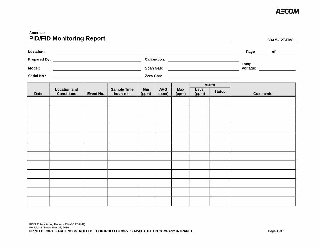
PID/FID Monitoring Report (S3AM-127-FM8) Revision 1 December 15, 2016
PRINTED COPIES ARE UNCONTROLLED. CONTROLLED COPY IS AVAILABLE ON COMPANY INTRANET. Page 1 of 1
Americas
PID/FID Monitoring Report S3AM-127-FM8
Location: Page of
Prepared By: Calibration:
Model: Span Gas: Lamp Voltage:
Serial No.: Zero Gas:
Date Location and Conditions Event No.
Sample Time hour: min
Min (ppm)
AVG (ppm)
Max (ppm)
Alarm
Comments Level (ppm)
Status

AECOM Health and Safety Plan
Appendix E - HASP.doc July 2018
Attachment F Material Safety Data Sheets

Appendix E - HASP.doc July 2018
Alconox SPI Supplies Division Structure Probe, Inc. P.O. Box 656 West Chester, PA 19381-0656 USA Phone: 1-(610)-436-5400 Fax: 1-(610)-436-5755 E-mail: [email protected] WWW: http://www.2spi.com Manufacturer's CAGE: 1P573 Material Safety Data Sheet SPI #01200-AB and #01200A-AB Alconox® Powdered Detergent
Section 1: Identification
Date Effective........... November 14, 2005 (most recent revision) Chemical Name/Synonyms... On Label: Alconox® Chemical Family.......... Anionic powdered detergent Emergencies Contacting CHEMTREC: 24 Hour Emergency Use Only #'s... Worldwide phone: 1-(703)-527-3887 Worldwide FAX: 1-(703)-741-6090 Toll-free phone: 1-(800)-424-9300 USA only Product or Trade Name.... SPI #01200-AB and #01200A-AB Alconox® Powdered Detergent CAS #. Not applicable Chemical Formula......... Not applicable
Section 2 Composition Component Name CAS # OSHA OSHA ACGIH ACGIH No hazardous ingredients in Alconox Powdered Detergent as defined by the OSHA Standard and Hazardous Substance List 29 CFR 1910 Subpart Z.
Hazardous Material Information System USA
Health 0
National Fire Protection Association USA
Fire Hazard 0
Reactivity 0
Personal Protection
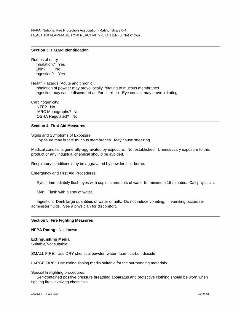
Appendix E - HASP.doc July 2018
NFPA (National Fire Protection Association) Rating (Scale 0-4): HEALTH=0 FLAMMABILITY=0 REACTIVITY=0 OTHER=0 Not known
Section 3: Hazard Identification
Routes of entry Inhalation? Yes Skin? No Ingestion? Yes Health Hazards (Acute and chronic): Inhalation of powder may prove locally irritating to mucous membranes. Ingestion may cause discomfort and/or diarrhea. Eye contact may prove irritating. Carcinogenicity: NTP? No IARC Monographs? No OSHA Regulated? No
Section 4: First Aid Measures
Signs and Symptoms of Exposure: Exposure may irritate mucous membranes. May cause sneezing. Medical conditions generally aggravated by exposure: Not established. Unnecessary exposure to this product or any industrial chemical should be avoided. Respiratory conditions may be aggravated by powder if air borne. Emergency and First Aid Procedures: Eyes: Immediately flush eyes with copious amounts of water for minimum 15 minutes. Call physician. Skin: Flush with plenty of water. Ingestion: Drink large quantities of water or milk. Do not induce vomiting. If vomiting occurs re-administer fluids. See a physician for discomfort.
Section 5: Fire Fighting Measures
NFPA Rating: Not known Extinguishing Media Suitable/Not suitable: SMALL FIRE: Use DRY chemical powder, water, foam, carbon dioxide LARGE FIRE: Use extinguishing media suitable for the surrounding materials. Special firefighting procedures: Self-contained positive pressure breathing apparatus and protective clothing should be worn when fighting fires involving chemicals.

Appendix E - HASP.doc July 2018
Unusual Fire/Explosion Hazards: None Hazardous thermal decomposition products: None known. Protection of fire fighters: No special measures are required. Flammable Limits: LEL: No data UEL: No data
Section 6: Accidental Release Measures
Personal precautions: No special precautions Environmental Precautions and Clean Up Methods: Material foams profusely. Recover as much as possible and flush remainder to sewer. Material is biodegradable.
Section 7: Handling and Storage
Material should be stored in a dry area to prevent caking.
Section 8: Exposure Controls and Personal Protection
Engineering controls: Normal ventilation is normally required when handling or using this product. Avoid conditions that could produce dusting. Personal Protective Equipment Respiratory system: Dust mask recommended but not required. Skin and body: Laboratory coat recommended but not required. Hands: Impervious gloves recommended Eyes: Goggles are recommended, especially when handling solutions irrespective of what they might be. Other: Wash hands before eating, drinking, or smoking.
Section 9: Physical and Chemical Properties
Physical State and Appearance: White powder interspersed with cream colored flakes. Odor: None Boiling Point: Not applicable Melting Point: Not applicable Density (water = 1): Not applicable

Appendix E - HASP.doc July 2018
Solubility: Appreciable, to 10% at ambient conditions. Octanol/water partition coefficient: Not available pH: Not known Flash Point: None Flammability: Non-flammable Autoignition temperature: Not applicable
Section 10: Stability and Reactivity
Chemical Stability: The product is stable Hazardous polymerization: Will not occur Conditions to Avoid: None Hazardous Products of Deposition: May release CO2 on burning. Reactions with Air and Water: Does not react with air, water or other common materials.
Section 11: Toxicological Information
Summary: Not considered to be toxic to humans or animals. Skin Effects: Can be locally irritating Eye Irritation: Can be irritating to the eyes Inhalation: Dust can be irritating to mucous membranes Sensitization: Not known Chronic toxicity: There is no known effect from the chronic exposure to this product.
Section 12: Ecological Information
Exotoxicity: Not know but it is expected to be low because the material is biodegradable. Environmental Fate: It is biodegradable. Bioaccumulation: Not expected to occur (because the material is biodegradable).
Section 13: Disposal Considerations

Appendix E - HASP.doc July 2018
This material is NOT classified as a hazardous material by RCRA. Use only licensed transporters and permitted disposal facilities and conform to all laws. Recycle to process, if possible. Germany water class: VCI WGK: No products were found. Methods of disposal; waste of residues; contaminated packaging: Waste must be disposed of in accordance with federal, state and local environmental control regulations.
Section 14: Transport Information
Proper Shipping Name: Non-Regulated, No dangerous cargo DOT Hazard Class: Non-Regulated, No dangerous cargo UN/NA ID: Non-Regulated, No dangerous cargo Packing Group: Not Applicable Labels: Not Regulated Marine Pollutant: No NAER Guidebook: Not Regulated DOT Status: Not Regulated Land-Road/Railway: ADR/RID Class: No dangerous cargo Sea: IMDG Class: No dangerous cargo Air: IATA-DGR Class: No dangerous cargo
Section 15: Regulatory Information
TSCA: All components of this product are listed on the TSCA 8(b) inventory. If identified components of this product are listed under the TSCA 12(b) Export Notification Rule, they will be listed below. TSCA 12(b) Component Listed under TSCA Section SARA Title 3: Section 313 Information/Emissions Reporting (40 CFR 372): Component Reporting Threshold SARA-Section 311/312: No components present in this product are subject to the reporting requirements of this statute. CERCLA Hazardous Substances and their Reportable Quantities:
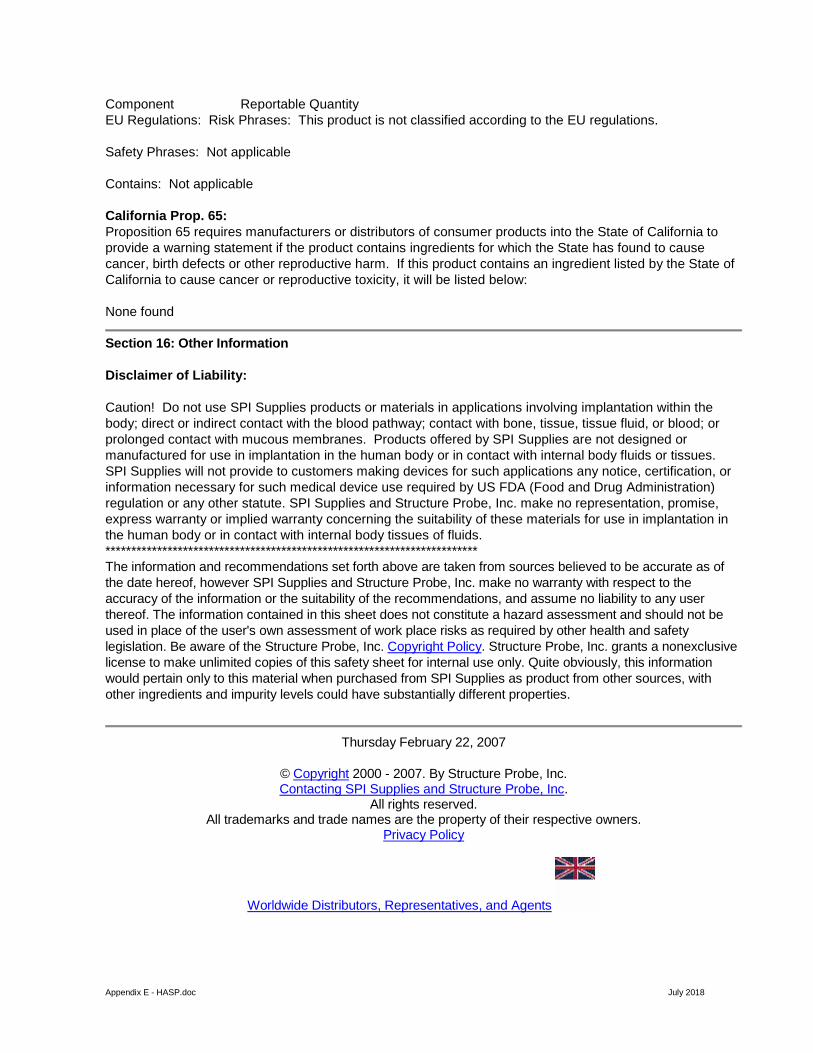
Appendix E - HASP.doc July 2018
Component Reportable Quantity EU Regulations: Risk Phrases: This product is not classified according to the EU regulations. Safety Phrases: Not applicable Contains: Not applicable California Prop. 65: Proposition 65 requires manufacturers or distributors of consumer products into the State of California to provide a warning statement if the product contains ingredients for which the State has found to cause cancer, birth defects or other reproductive harm. If this product contains an ingredient listed by the State of California to cause cancer or reproductive toxicity, it will be listed below: None found
Section 16: Other Information
Disclaimer of Liability: Caution! Do not use SPI Supplies products or materials in applications involving implantation within the body; direct or indirect contact with the blood pathway; contact with bone, tissue, tissue fluid, or blood; or prolonged contact with mucous membranes. Products offered by SPI Supplies are not designed or manufactured for use in implantation in the human body or in contact with internal body fluids or tissues. SPI Supplies will not provide to customers making devices for such applications any notice, certification, or information necessary for such medical device use required by US FDA (Food and Drug Administration) regulation or any other statute. SPI Supplies and Structure Probe, Inc. make no representation, promise, express warranty or implied warranty concerning the suitability of these materials for use in implantation in the human body or in contact with internal body tissues of fluids. ************************************************************************ The information and recommendations set forth above are taken from sources believed to be accurate as of the date hereof, however SPI Supplies and Structure Probe, Inc. make no warranty with respect to the accuracy of the information or the suitability of the recommendations, and assume no liability to any user thereof. The information contained in this sheet does not constitute a hazard assessment and should not be used in place of the user's own assessment of work place risks as required by other health and safety legislation. Be aware of the Structure Probe, Inc. Copyright Policy. Structure Probe, Inc. grants a nonexclusive license to make unlimited copies of this safety sheet for internal use only. Quite obviously, this information would pertain only to this material when purchased from SPI Supplies as product from other sources, with other ingredients and impurity levels could have substantially different properties.
Thursday February 22, 2007
© Copyright 2000 - 2007. By Structure Probe, Inc. Contacting SPI Supplies and Structure Probe, Inc.
All rights reserved. All trademarks and trade names are the property of their respective owners.
Privacy Policy
Worldwide Distributors, Representatives, and Agents
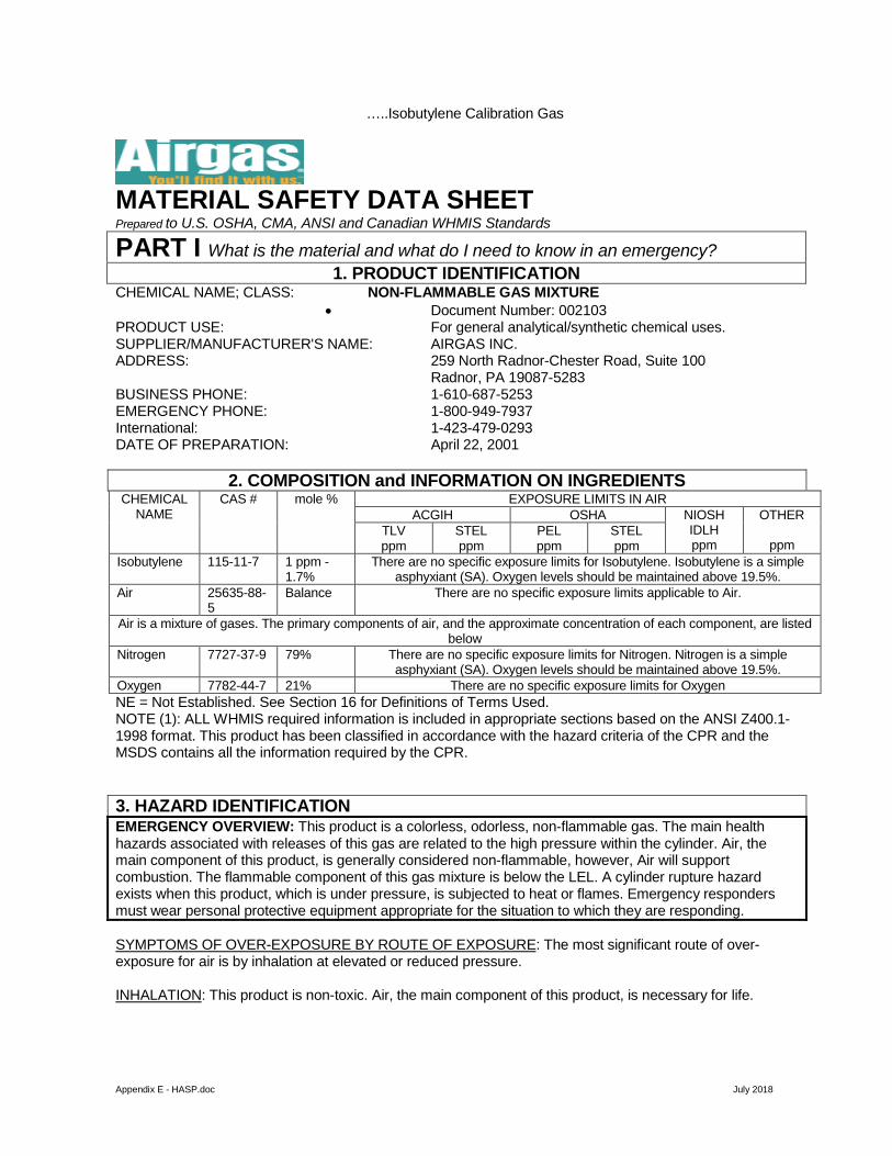
Appendix E - HASP.doc July 2018
…..Isobutylene Calibration Gas
MATERIAL SAFETY DATA SHEET Prepared to U.S. OSHA, CMA, ANSI and Canadian WHMIS Standards
PART I What is the material and what do I need to know in an emergency? 1. PRODUCT IDENTIFICATION
CHEMICAL NAME; CLASS: NON-FLAMMABLE GAS MIXTURE • Document Number: 002103
PRODUCT USE: For general analytical/synthetic chemical uses. SUPPLIER/MANUFACTURER'S NAME: AIRGAS INC. ADDRESS: 259 North Radnor-Chester Road, Suite 100
Radnor, PA 19087-5283 BUSINESS PHONE: 1-610-687-5253 EMERGENCY PHONE: 1-800-949-7937 International: 1-423-479-0293 DATE OF PREPARATION: April 22, 2001
2. COMPOSITION and INFORMATION ON INGREDIENTS CHEMICAL
NAME CAS # mole % EXPOSURE LIMITS IN AIR
ACGIH OSHA NIOSH IDLH ppm
OTHER
ppm TLV ppm
STEL ppm
PEL ppm
STEL ppm
Isobutylene 115-11-7 1 ppm - 1.7%
There are no specific exposure limits for Isobutylene. Isobutylene is a simple asphyxiant (SA). Oxygen levels should be maintained above 19.5%.
Air 25635-88-5
Balance There are no specific exposure limits applicable to Air.
Air is a mixture of gases. The primary components of air, and the approximate concentration of each component, are listed below
Nitrogen 7727-37-9 79% There are no specific exposure limits for Nitrogen. Nitrogen is a simple asphyxiant (SA). Oxygen levels should be maintained above 19.5%.
Oxygen 7782-44-7 21% There are no specific exposure limits for Oxygen NE = Not Established. See Section 16 for Definitions of Terms Used. NOTE (1): ALL WHMIS required information is included in appropriate sections based on the ANSI Z400.1-1998 format. This product has been classified in accordance with the hazard criteria of the CPR and the MSDS contains all the information required by the CPR.
3. HAZARD IDENTIFICATION EMERGENCY OVERVIEW: This product is a colorless, odorless, non-flammable gas. The main health hazards associated with releases of this gas are related to the high pressure within the cylinder. Air, the main component of this product, is generally considered non-flammable, however, Air will support combustion. The flammable component of this gas mixture is below the LEL. A cylinder rupture hazard exists when this product, which is under pressure, is subjected to heat or flames. Emergency responders must wear personal protective equipment appropriate for the situation to which they are responding. SYMPTOMS OF OVER-EXPOSURE BY ROUTE OF EXPOSURE: The most significant route of over-exposure for air is by inhalation at elevated or reduced pressure. INHALATION: This product is non-toxic. Air, the main component of this product, is necessary for life.
Appendix E - HASP.doc July 2018
OTHER POTENTIAL HEALTH EFFECTS: Contact with rapidly expanding gases (which are released under high pressure) may cause frostbite. Symptoms of frostbite include change in skin color to white or grayish-yellow. The pain after contact with liquid can quickly subside. HEALTH EFFECTS OR RISKS FROM EXPOSURE: An Explanation in Lay Terms. Over-exposure to this product may cause the following health effects: ACUTE: The most significant hazards associated with compressed air is the pressure hazard. Contact with rapidly expanding gases (which are released under high pressure) may cause frostbite. Symptoms of frostbite include change in skin color to white or grayish-yellow. The pain after contact with liquid can quickly subside. CHRONIC: There are currently no known adverse health effects associated with chronic exposure to this gas. TARGET ORGANS: ACUTE: Respiratory system under ambient low pressure conditions. Central nervous system under ambient high pressure conditions. CHRONIC: None expected.
PART II What should I do if a hazardous situation occurs? 4. FIRST-AID MEASURES
RESCUERS SHOULD NOT ATTEMPT TO RETRIEVE VICTIMS OF EXPOSURE TO THIS PRODUCT WITHOUT ADEQUATE PERSONAL PROTECTIVE EQUIPMENT. At a minimum, Self-Contained Breathing Apparatus equipment should be worn. Victim(s) must be taken for medical attention. Rescuers should be taken for medical attention, if necessary. Take copy of label and MSDS to physician or other health professional with victim(s). Remove victim(s) to fresh air, as quickly as possible. In case of eye contact which leads to irritation, immediately flush eyes with copious amounts of water for at least 15 minutes. If not breathing, give artificial respiration. If breathing is difficult, give oxygen. Only trained personnel should administer supplemental oxygen. In case of frostbite, place the frostbitten part in warm water. DO NOT USE HOT WATER. If warm water is not available, or is impractical to use, wrap the affected parts gently in blankets. Alternatively, if the fingers or hands are frostbitten, place the affected area in the armpit. Encourage victim to gently exercise the affected part while being warmed. Seek immediate medical attention. MEDICAL CONDITIONS AGGRAVATED BY EXPOSURE: Acute or chronic respiratory conditions, as well as disorders involving the “Target Organs”, as listed in Section 3 (Hazard Information), may be aggravated by overexposure to the components of this product. RECOMMENDATIONS TO PHYSICIANS: Administer oxygen as soon as possible, following exposure.
5. FIRE-FIGHTING MEASURES FLASH POINT: Not applicable. AUTOIGNITION TEMPERATURE: Not applicable. FLAMMABLE LIMITS (in air by volume, %):
Lower (LEL): Not applicable. Upper (UEL): Not applicable.
5. FIRE-FIGHTING MEASURES (Continued) FIRE EXTINGUISHING MATERIALS: Non-flammable gas. Use extinguishing media appropriate for surrounding fire. UNUSUAL FIRE AND EXPLOSION HAZARDS: When involved in a fire, this material may decompose and produce toxic gases including carbon monoxide and carbon dioxide. Additionally, when involved in fire, the cylinders may rupture. Explosion Sensitivity to Mechanical Impact: Not Sensitive. Explosion Sensitivity to Static Discharge: Not Sensitive. SPECIAL FIRE-FIGHTING PROCEDURES: Structural firefighters must wear Self-Contained Breathing Apparatus and full protective equipment. Move fire-exposed cylinders from area, if it can be done without risk to fire-fighters. Withdraw immediately in case of rising sounds from venting pressure relief devices or any discoloration of tanks or cylinders due to a fire.

Appendix E - HASP.doc July 2018
6. ACCIDENTAL RELEASE MEASURES SPILL AND LEAK RESPONSE: Uncontrolled releases should be responded to by trained personnel using pre-planned procedures. Proper protective equipment should be used. In case of a release, clear the affected area, protect people, and respond with trained personnel. Minimum Personal Protective Equipment should be Level D: safety glasses, and mechanically-resistant gloves. Level B, which includes the use of Self- Contained Breathing Apparatus, should be worn when oxygen levels are below 19.5% or are unknown. Locate and seal the source of the leaking gas. If this does not stop the release (or if it is not possible to reach the valve), allow the gas to release in place or remove it to a safe area and allow the gas to be released there.
PART III How can I prevent hazardous situations from occurring? 7. HANDLING and STORAGE
WORK PRACTICES AND HYGIENE PRACTICES: Do not eat or drink while handling chemicals. STORAGE AND HANDLING PRACTICES: Cylinders should be stored in dry, well-ventilated areas away from sources of heat. Compressed gases can present significant safety hazards. Store containers away from heavily trafficked areas and emergency exits. SPECIAL PRECAUTIONS FOR HANDLING GAS CYLINDERS: Protect cylinders against physical damage. Store in cool, dry, well-ventilated, fireproof area, away from flammable or combustible materials and corrosive atmospheres. Store away from heat and ignition sources and out of direct sunlight. Do not store near elevators, corridors or loading docks. Do not allow area where cylinders are stored to exceed 52°C (125°F). Isolate from incompatible materials including flammable materials (see Section 10, Stability and Reactivity), which can burn violently. Use only storage containers and equipment (pipes, valves, fittings to relieve pressure, etc.) designed for the storage of Air. Do not store containers where they can come into contact with moisture. Cylinders should be stored upright and be firmly secured to prevent falling or being knocked over. Cylinders can be stored in the open, but in such cases, should be protected against extremes of weather and from the dampness of the ground to prevent rusting. Never tamper with pressure relief devices in valves and cylinders. The following rules are applicable to situations in which cylinders are being used: Before Use: Move cylinders with a suitable hand-truck. Do not drag, slide or roll cylinders. Do not drop cylinders or permit them to strike each other. Secure cylinders firmly. Leave the valve protection cap in-place until cylinder is ready for use. During Use: Use designated CGA fittings and other support equipment. Do not use adapters. Do not heat cylinder by any means to increase the discharge rate of the product from the cylinder. Use check valve or trap in discharge line to prevent hazardous backflow into the cylinder. Do not use oils or grease on gas-handling fittings or equipment. After Use: Close main cylinder valve. Replace valve protection cap. Mark empty cylinders “EMPTY”. NOTE: Use only DOT or ASME code containers. Earth-ground and bond all lines and equipment associated with this product. Close valve after each use and when empty. Cylinders must not be recharged except by or with the consent of owner. For additional information refer to the Compressed Gas Association Pamphlet P-1, Safe Handling of Compressed Gases in Containers. Additionally, refer to CGA Bulletin SB-2 “Oxygen Deficient Atmospheres”. PROTECTIVE PRACTICES DURING MAINTENANCE OF CONTAMINATED EQUIPMENT: Follow practices indicated in Section 6 (Accidental Release Measures). Make certain application equipment is locked and tagged out safely. Purge gas handling equipment with inert gas (i.e. nitrogen) before attempting repairs. Always use product in areas where adequate ventilation is provided.
8. EXPOSURE CONTROLS - PERSONAL PROTECTION VENTILATION AND ENGINEERING CONTROLS: Use with adequate ventilation. RESPIRATORY PROTECTION: Maintain Oxygen levels above 19.5% in the workplace. If respiratory protection is needed, use only protection authorized in the U.S. Federal OSHA Standard (29 CFR 1910.134), applicable U.S. State regulations, or the Canadian CSA Standard Z94.4-93 and applicable standards of Canadian Provinces. Oxygen levels below 19.5% are considered IDLH by OSHA. In such atmospheres, use of a full facepiece pressure/demand SCBA or a full facepiece, supplied air respirator with auxiliary self-contained air supply is required under OSHA’s Respiratory Protection Standard (1910.134-1998).
Appendix E - HASP.doc July 2018
EYE PROTECTION: Splash goggles, face-shields or safety glasses. If necessary, refer to U.S. OSHA 29 CFR 1910.133, or Canadian Standards. HAND PROTECTION: Wear mechanically-resistant gloves when handling cylinders of this product. If necessary, refer to U.S. OSHA 29 CFR 1910.138 or appropriate Standards of Canada. BODY PROTECTION: Use body protection appropriate for task. If a hazard of injury to the feet exists due to falling objects, rolling objects, where objects may pierce the soles of the feet or where employee’s feet may be exposed to electrical hazards, use foot protection, as described in U.S. OSHA 29 CFR.
9. PHYSICAL and CHEMICAL PROPERTIES The following information is for Air, the main component of this product , unless otherwise stated: RELATIVE VAPOR DENSITY: 1 EVAPORATION RATE (nBuAc = 1): Not applicable. SPECIFIC GRAVITY: Not applicable. FREEZING POINT: -216.2°C (-357.2°F) SOLUBILITY IN WATER: 1.49% (v/v) BOILING POINT @ 1 atmos: -194.3°C(-317.8°F) VAPOR PRESSURE, mmHg @ 20°C:. pH: Not applicable. EXPANSION RATIO: Not applicable. VAPOR PRESSURE: Not applicable. SPECIFIC VOLUME: 13.3 ft3/lb; (0.833 m3/kg) ODOR THRESHOLD: Not applicable. COEFFICIENT WATER/OIL DISTRIBUTION: Not applicable.
The following information is pertinent to this gas mixture: APPEARANCE, ODOR AND COLOR: This product is a colorless, odorless gas. HOW TO DETECT THIS SUBSTANCE (warning properties): There are no distinctive properties to this product. In terms of leak detection, fittings and joints can be painted with a soap solution to detect leaks, which will be indicated by a bubble formation.
10. STABILITY and REACTIVITY STABILITY: Normally stable. DECOMPOSITION PRODUCTS: None known. MATERIALS WITH WHICH SUBSTANCE IS INCOMPATIBLE. Air (the main component of this product) is not compatible with fuels, in that air will support combustion. The Isobutylene component of this mixture is incompatible with Strong oxidizers (e.g., chlorine, bromine pentafluoride, oxygen, oxygen difluoride, and nitrogen trifluoride). HAZARDOUS POLYMERIZATION: Will not occur. CONDITIONS TO AVOID: Contact with incompatible materials and exposure to heat, sparks and other sources of ignition. Cylinders exposed to high temperatures or direct flame can rupture or burst.
PART III How can I prevent hazardous situations from occurring? 11. TOXICOLOGICAL INFORMATION
TOXICITY DATA: The following toxicology data are for the components of this gas mixture present at a level greater than 1 mole %: ISOBUTYLENE: LC50 (Inhalation-Rat) 620 gm/m3/4 hours LC50 (Inhalation-Mouse) 415 gm/m3/2 hours SUSPECTED CANCER AGENT: No component of this gas mixture is found on the following lists: FEDERAL OSHA Z LIST, NTP, CAL/OSHA, IARC, and therefore is not considered to be, nor suspected to be, cancer causing agents by these agencies. IRRITANCY OF PRODUCT: Contact with rapidly expanding gases can cause frostbite and damage to exposed skin and eyes. SENSITIZATION OF PRODUCT: No component of this product is a skin or respiratory sensitizer. REPRODUCTIVE TOXICITY INFORMATION: Listed below is information concerning the effects of this product and its components on the human reproductive system. Mutagenicity: This product is not reported to cause mutagenic effects in humans. Embryotoxicity: This product is not reported to cause embryotoxic effects in humans. Teratogenicity: This product is not reported to cause teratogenic effects in humans. Reproductive Toxicity: This product is not reported to cause adverse reproductive effects in humans.

Appendix E - HASP.doc July 2018
A mutagen is a chemical which causes permanent changes to genetic material (DNA) such that the changes will propagate through generation lines. An embryotoxin is a chemical which causes damage to a developing embryo (i.e. within the first eight weeks of pregnancy in humans), but the damage does not propagate across generational lines. A teratogen is a chemical which causes damage to a developing fetus, but the damage does not propagate across generational lines. A reproductive toxin is any substance which interferes in any way with the reproductive process. BIOLOGICAL EXPOSURE INDICES: Biological Exposure Indices (BEIs) have been determined for the components of this product are as follows:
12. ECOLOGICAL INFORMATION ENVIRONMENTAL STABILITY: This gas will be dissipated rapidly in well-ventilated areas. EFFECT OF MATERIAL ON PLANTS or ANIMALS: No adverse effect is anticipated to occur to plant-life, except for frost produced in the presence of rapidly expanding gases. EFFECT OF CHEMICAL ON AQUATIC LIFE: No evidence of an adverse effect of this product on aquatic life is currently available.
13. DISPOSAL CONSIDERATIONS PREPARING WASTES FOR DISPOSAL: Product removed from cylinder must be disposed of in accordance with appropriate U.S. Federal, State and local regulations or with regulations of Canada and its Provinces. Return cylinders with residual product to Airgas, Inc. Do not dispose of locally.
14. TRANSPORTATION INFORMATION THIS GAS MIXTURE IS HAZARDOUS AS DEFINED BY 49 CFR 172.101 BY THE U.S. DEPARTMENT OF TRANSPORTATION. PROPER SHIPPING NAME: Compressed gases, n.o.s. (Air, Isobutylene) HAZARD CLASS NUMBER and DESCRIPTION: 2.2 (Compressed Gas) UN IDENTIFICATION NUMBER: UN 1956 PACKING GROUP: Not Applicable DOT LABEL(S) REQUIRED: Compressed Gas NORTH AMERICAN EMERGENCY RESPONSE GUIDEBOOK NUMBER (2000): 126 TRANSPORT CANADA, TRANSPORTATION OF DANGEROUS GOODS REGULATIONS: This gas mixture is considered as dangerous goods, per regulations of Transport Canada. Use the above information for the preparation of Canadian Shipments.
15. REGULATORY INFORMATION ADDITIONAL U.S. REGULATIONS: U.S. SARA REPORTING REQUIREMENTS: The components of this gas mixture are not subject to the reporting requirements of Sections 302, 304 and 313 of Title III of the Superfund Amendments and Reauthorization Act. U.S. SARA THRESHOLD PLANNING QUANTITY: There are no specific Threshold Planning Quantities for this material. The default Federal MSDS submission and inventory requirement filing threshold of 10,000 lb (4,540 kg) may apply, per 40 CFR 370.20. U.S. CERCLA REPORTABLE QUANTITY (RQ): Not applicable. U.S. TSCA INVENTORY STATUS: The components of this product are listed on the TSCA Inventory. OTHER U.S. FEDERAL REGULATIONS: Not applicable. U.S. STATE REGULATORY INFORMATION: The components of this gas mixture are covered under specific State regulations, as denoted below: Alaska - Designated Toxic and Hazardous Substances: None. California - Permissible Exposure Limits for Chemical Contaminants: None. Florida - Substance List: Isobutylene. Illinois - Toxic Substance List: None. Kansas - Section 302/313 List: None. Minnesota - List of Hazardous Substances: Isobutylene. Massachusetts - Substance List: None. Missouri - Employer Information/Toxic Substance List: None. New Jersey - Right to Know Hazardous Substance List: Isobutylene.

Appendix E - HASP.doc July 2018
North Dakota - List of Hazardous Chemicals, Reportable Quantities: None. Pennsylvania - Hazardous Substance List: Isobutylene. Rhode Island - Hazardous Substance List: None. Texas - Hazardous Substance List: None. West Virginia - Hazardous Substance List: None. Wisconsin - Toxic and Hazardous Substances: None. CALIFORNIA SAFE DRINKING WATER AND TOXIC ENFORCEMENT ACT (PROPOSITION 65): No component of this product is on the California Proposition 65 Lists. LABELING: CAUTION: HIGH PRESSURE GAS.
MAY ACCELERATE COMBUSTION. Keep oil and grease away. Use equipment rated for cylinder pressure. Close valve after each use and when empty. Use in accordance with the Material Safety Data Sheet.
FIRST-AID: IF INHALED, remove to fresh air. If not breathing, give artificial respiration. If breathing is difficult, give oxygen. Call a physician. IN CASE OF FROSTBITE, obtain immediate medial attention. DO NOT REMOVE THIS PRODUCT LABEL.
ADDITIONAL CANADIAN REGULATIONS: CANADIAN DSL INVENTORY: The components of this product are listed on the DSL Inventory. OTHER CANADIAN REGULATIONS: Not applicable. CANADIAN ENVIRONMENTAL PROTECTION ACT (CEPA) PRIORITIES SUBSTANCES LISTS: The components of this product are not on the CEPA Priorities Substances Lists. CANADIAN WHMIS SYMBOLS: Class A: Compressed Gases
16. OTHER INFORMATION PREPARED BY: CHEMICAL SAFETY ASSOCIATES, Inc.
9163 Chesapeake Drive, San Diego, CA 92123-1002 858/565-0302
The information contained herein is based on data considered accurate. However, no warranty is expressed or implied regarding the accuracy of these data or the results to be obtained from the use thereof. AirGas, Inc. assumes no responsibility for injury to the vendee or third persons proximately caused by the material if reasonable safety procedures are not adhered to as stipulated in the data sheet. Additionally, AirGas, Inc. assumes no responsibility for injury to vendee or third persons proximately caused by abnormal use of the material even if reasonable safety procedures are followed. Furthermore, vendee assumes the risk in his use of the material.
DEFINITIONS OF TERMS A large number of abbreviations and acronyms appear on a MSDS. Some of these which are commonly used include the following: CAS #: This is the Chemical Abstract Service Number which uniquely identifies each constituent. EXPOSURE LIMITS IN AIR: ACGIH - American Conference of Governmental Industrial Hygienists, a professional association which establishes exposure limits. TLV - Threshold Limit Value - an airborne concentration of a substance which represents conditions under which it is generally believed that nearly all workers may be repeatedly exposed without adverse effect. The duration must be considered, including the 8-hour Time Weighted Average (TWA), the 15-minute Short Term Exposure Limit, and the instantaneous Ceiling Level (C). Skin absorption effects must also be considered. OSHA - U.S. Occupational Safety and Health Administration. PEL - Permissible Exposure Limit - This exposure value means exactly the same as a TLV, except that it is enforceable by OSHA. The OSHA Permissible Exposure Limits are based in the 1989 PELs and the June, 1993 Air Contaminants Rule (Federal Register: 58: 35338-35351 and 58: 40191). Both the current PELs and the vacated PELs are indicated. The phrase, “Vacated 1989 PEL,” is placed next to the PEL which was vacated by Court Order.

Appendix E - HASP.doc July 2018
IDLH - Immediately Dangerous to Life and Health - This level represents a concentration from which one can escape within 30- minutes without suffering escape-preventing or permanent injury. The DFG - MAK is the Republic of Germany’s Maximum Exposure Level, similar to the U.S. PEL. NIOSH is the National Institute of Occupational Safety and Health, which is the research arm of the U.S. Occupational Safety and Health Administration (OSHA). NIOSH issues exposure guidelines called Recommended Exposure Levels (RELs). When no exposure guidelines are established, an entry of NE is made for reference. HAZARD RATINGS: HAZARDOUS MATERIALS IDENTIFICATION SYSTEM: Health Hazard: 0 (minimal acute or chronic exposure hazard); 1 (slight acute or chronic exposure hazard); 2 (moderate acute or significant chronic exposure hazard); 3 (severe acute exposure hazard; onetime overexposure can result in permanent injury and may be fatal); 4 (extreme acute exposure hazard; onetime overexposure can be fatal). Flammability Hazard: 0 (minimal hazard); 1 (materials that require substantial pre-heating before burning); 2 (combustible liquid or solids; liquids with a flash point of 38-93C [100-200F]); 3 (Class IB and IC flammable liquids with flash points below 38C [100F]); 4 (Class IA flammable liquids with flash points below 23C [73F] a nd boiling points below 38C [100F]. Reactivity Ha za rd: 0 (normally stable); 1 (material that can become unstable at elevated temperatures or which can react slightly with water); 2 (materials that are unstable but do not detonate or which can react violently with water); 3 (materials that can detonate when initiated or which can react explosively with water); 4 (materials that can detonate at normal temperatures or pressures). PERSONAL PROTECTIVE EQUIPMENT CODES: B: Gloves and goggles; C: Gloves, goggles, rubber apron (appropriate body protection); D: Gloves, goggles, faceshield; rubber apron (appropriate body protection);. X: Special attention should be given to PPE Selection. NATIONAL FIRE PROTECTION ASSOCIATION: Health Hazard: 0 (material that on exposure under fire conditions would offer no hazard beyond that of ordinary combustible materials); 1 (materials that on exposure under fire conditions could cause irritation or minor residual injury); 2 (materials that on intense or continued exposure under fire conditions could cause temporary incapacitation or possible residual injury); 3 (materials that can on short exposure could cause serious temporary or residual injury); 4 (materials that under very short exposure could cause death or major residual injury). Flammability Hazard and Reactivity Hazard: Refer to definitions for “Hazardous Materials Identification System”. FLAMMABILITY LIMITS IN AIR: Much of the information related to fire and explosion is derived from the National Fire Protection Association (NFPA). Flash Point – Minimum temperature at which a liquid gives off sufficient vapors to form an ignitable mixture with air. Autoignition Temperature: The minimum temperature required to initiate combustion in air with no other source of ignition. LEL - the lowest percent of vapor in air, by volume, that will explode or ignite in the presence of an ignition source. UEL – the highest percent of vapor in air, by volume, that will explode or ignite in the presence of an ignition source. TOXICOLOGICAL INFORMATION: Possible health hazards as derived from human data, animal studies, or from the results of studies with similar compounds are presented. Definitions of some terms used in this section are: LD50 - Lethal Dose (solids & liquids) which kills 50% of the exposed animals; LC50 – Lethal Concentration (gases) which kills 50% of the exposed animals; ppm concentration expressed in parts of material per million parts of air or water; mg/m3 concentration expressed in weight of substance per volume of air; mg/kg quantity of material, by weight, administered to a test subject, based on their body weight in kg. Data from several sources are used to evaluate the cancer-causing potential of the material. The sources are: IARC - the International Agency for Research on Cancer; NTP - the National Toxicology Program, RTECS - the Registry of Toxic Effects of Chemical Substances, OSHA and CAL/OSHA. IARC and NTP rate chemicals on a scale of decreasing potential to cause human cancer with rankings from 1 to 4. Subrankings (2A, 2B, etc.) are also used. Other measures of toxicity include TDLo, the lowest dose to cause a symptom and TCLo the lowest concentration to cause a symptom; TDo, LDLo, and LDo, or TC, TCo, LCLo, and LCo, the lowest dose (or concentration) to cause lethal or toxic effects. BEI - Biological Exposure Indices, represent the levels of determinants which are most likely to be observed in specimens collected from a healthy worker who has been exposed to chemicals to the same extent as a worker with inhalation exposure to the TLV. Ecological Information: EC is the effect concentration in water.

Appendix E - HASP.doc July 2018
REGULATORY INFORMATION: This section explains the impact of various laws and regulations on the material. EPA is the U.S. Environmental Protection Agency. WHMIS is the Canadian Workplace Hazardous Materials Information System. DOT and TC are the U.S. Department of Transportation and the Transport Canada, respectively. Superfund Amendments and Reauthorization Act (SARA); the Canadian Domestic/Non-Domestic Substances List (DSL/NDSL); the U.S. Toxic Substance Control Act (TSCA); Marine Pollutant status according to the DOT; the Comprehensive Environmental Response, Compensation, and Liability Act (CERCLA or Superfund); and various state regulations.
AECOM Interim Site Management Plan
Site Management Plan, Site #241063
APPENDIX F
Community Air Monitoring Plan

Prepared for: Submitted by: National Grid AECOM Brooklyn, New York New York, New York 60144468 July 2018
Environment
Community Air Monitoring Plan
(Appendix F of the Interim Site Management Plan)
Former Jamaica Gas Light Company Manufactured Gas Plant Site Jamaica, Queens, New York NYSDEC Site No.: 241063 Order on Consent Index #: A2-0552-0606

Prepared for: Submitted by: National Grid AECOM Brooklyn, New York New York, New York 60144468 July 2018
Environment
Community Air Monitoring Plan
_________________________________ Prepared By:
_________________________________ Reviewed By:
Former Jamaica Gas Light Company Manufactured Gas Plant Site Jamaica, Queens, New York NYSDEC Site No.: 241063 Order on Consent Index #:A2-0552-0606

AECOM Community Air Monitoring Plan
Appendix F - CAMP.doc July 2018
i
Contents
1.0 Introduction ................................................................................................................... 1-1
2.0 Constituents of Concern and Action Levels .............................................................. 2-1
3.0 Air Monitoring Equipment and Methods ..................................................................... 3-1
3.1 Volatile Organic Compounds and Benzene Monitoring ..................................................... 3-1 3.1.1 Ambient Air Monitoring ......................................................................................... 3-1
3.2 Particulate (Dust) Monitoring .............................................................................................. 3-1
4.0 Emission Control Plan .................................................................................................. 4-1
4.1 Ambient Air .......................................................................................................................... 4-1
5.0 Odor Control Procedures ............................................................................................. 5-1
5.1 Potential Sources of Odors ................................................................................................. 5-1
5.2 Odor Monitoring ................................................................................................................... 5-1
5.3 General Site Controls .......................................................................................................... 5-1
5.4 Secondary Site Controls ..................................................................................................... 5-2
5.5 Record Keeping and Communication ................................................................................. 5-3
6.0 Documentation and Reporting .................................................................................... 6-1

AECOM Community Air Monitoring Plan
Appendix F - CAMP.doc July 2018
ii
List of Appendices Appendix A Vapor Suppression Information
List of Tables
Table 1-1 Property Owners and Addresses .............................................................................................. 1-1
Table 4-1 Emergency Contacts and Telephone Numbers ....................................................................... 4-3
List of Figures
Figure 4-1 Vapor Emission Response Chart ............................................................................................ 4-2
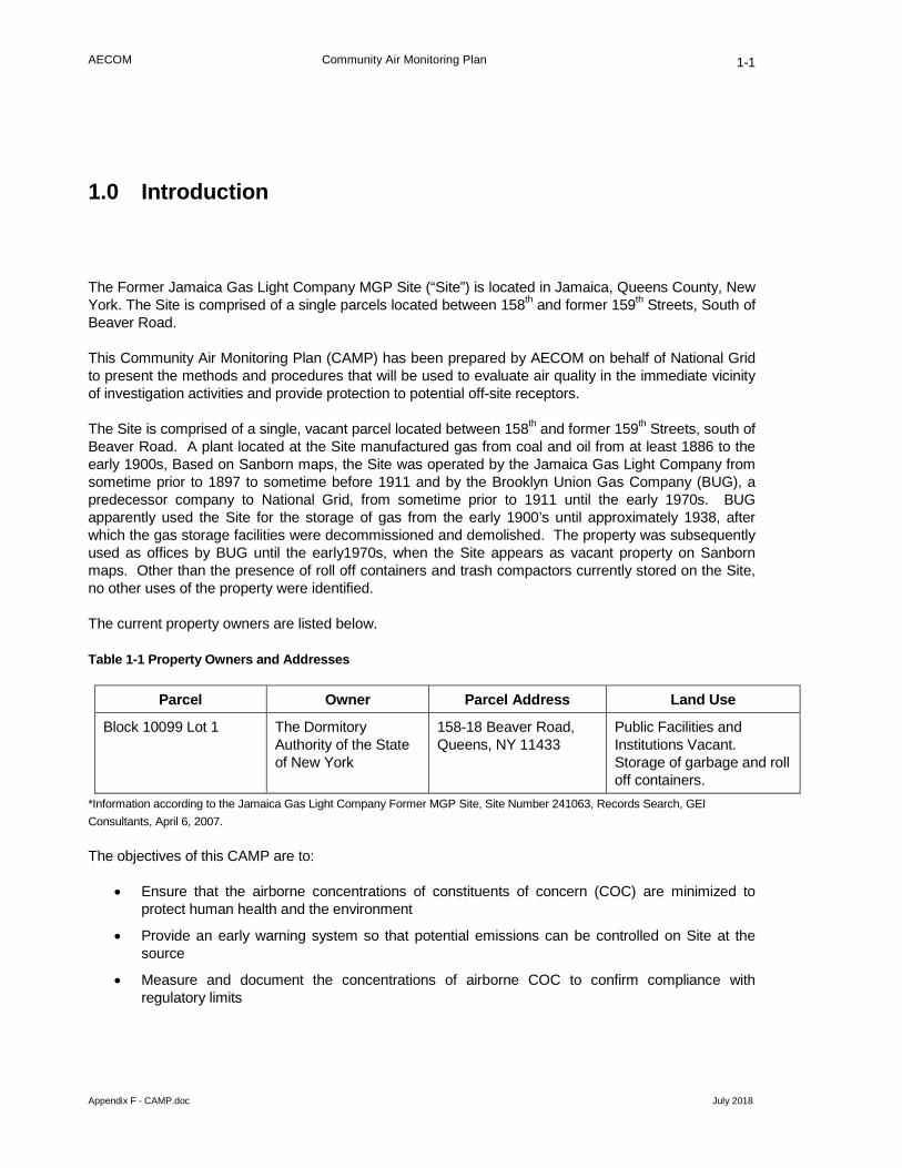
AECOM Community Air Monitoring Plan
Appendix F - CAMP.doc July 2018
1-1
1.0 Introduction
The Former Jamaica Gas Light Company MGP Site (“Site”) is located in Jamaica, Queens County, New York. The Site is comprised of a single parcels located between 158th and former 159th Streets, South of Beaver Road.
This Community Air Monitoring Plan (CAMP) has been prepared by AECOM on behalf of National Grid to present the methods and procedures that will be used to evaluate air quality in the immediate vicinity of investigation activities and provide protection to potential off-site receptors.
The Site is comprised of a single, vacant parcel located between 158th and former 159th Streets, south of Beaver Road. A plant located at the Site manufactured gas from coal and oil from at least 1886 to the early 1900s, Based on Sanborn maps, the Site was operated by the Jamaica Gas Light Company from sometime prior to 1897 to sometime before 1911 and by the Brooklyn Union Gas Company (BUG), a predecessor company to National Grid, from sometime prior to 1911 until the early 1970s. BUG apparently used the Site for the storage of gas from the early 1900’s until approximately 1938, after which the gas storage facilities were decommissioned and demolished. The property was subsequently used as offices by BUG until the early1970s, when the Site appears as vacant property on Sanborn maps. Other than the presence of roll off containers and trash compactors currently stored on the Site, no other uses of the property were identified.
The current property owners are listed below.
Table 1-1 Property Owners and Addresses
Parcel Owner Parcel Address Land Use
Block 10099 Lot 1 The Dormitory Authority of the State of New York
158-18 Beaver Road, Queens, NY 11433
Public Facilities and Institutions Vacant. Storage of garbage and roll off containers.
*Information according to the Jamaica Gas Light Company Former MGP Site, Site Number 241063, Records Search, GEI Consultants, April 6, 2007.
The objectives of this CAMP are to:
• Ensure that the airborne concentrations of constituents of concern (COC) are minimized to protect human health and the environment
• Provide an early warning system so that potential emissions can be controlled on Site at the source
• Measure and document the concentrations of airborne COC to confirm compliance with regulatory limits

AECOM Community Air Monitoring Plan
Appendix F - CAMP.doc July 2018
1-2
The community air monitoring will be performed around the Site perimeter, and will measure the concentrations of organic vapors and dust during all ground-intrusive activities (excavation, utility work test pitting, soil boring, and well installation).
This CAMP is Attachment F of the ISMP and is directed primarily toward protection of on-site workers within the designated work zones.

AECOM Community Air Monitoring Plan
Appendix F - CAMP.doc July 2018
2-1
2.0 Constituents of Concern and Action Levels
The constituents of concern are volatile and semi-volatile organic compounds (VOCs and SVOCs). The primary VOCs of concern are benzene, ethylbenzene, toluene, and xylene (BTEX compounds). VOCs are more volatile than SVOCs and are generally of greater concern when monitoring the air quality during MGP Site investigations.
Airborne dust is also a concern and must be monitored and controlled due to its ability to co-transport adsorbed constituents and because of its nuisance properties.
Odors, though not necessarily indicative of high constituent concentrations, could create a nuisance (especially when working within or in close proximity to existing buildings and building entrances) and will be monitored and controlled to the extent practicable.
State and federal regulatory agencies have provided action levels for many of these constituents. The action levels are the allowable airborne concentrations above which respiratory protection or other health and safety controls are required. For work at the former MGP Site, the following levels should not be exceeded for more than 15 consecutive minutes at the downwind perimeter of the Site:
• Benzene 1 part per million (ppm)
• Total VOCs 5 ppm
• Dust 100 micrograms per cubic meter (µg/m3)
The action levels cited here are above (in addition to) the background ambient (upwind) concentration.

AECOM Community Air Monitoring Plan
Appendix F - CAMP.doc July 2018
3-1
3.0 Air Monitoring Equipment and Methods
Air quality monitoring will be performed for total VOCs, benzene, and dust as outlined below.
Two perimeter locations will be established each day and an air monitoring technician will check the instrumentation at each of these locations frequently during the work. Typically there will be monitoring locations at one upwind Site perimeter location and one downwind perimeter location. Upwind concentrations will be measured at the start of each workday and periodically thereafter to establish background conditions. Field personnel will be prepared to monitor multiple locations in the event that there is little wind or if the wind direction changes frequently.
The monitoring instruments will be calibrated at the start of each workday, and again during the day if the performance of an instrument is in question.
3.1 Volatile Organic Compounds and Benzene Monitoring
3.1.1 Ambient Air Monitoring
VOC monitoring will be performed continuously using three field photoionization detectors (PIDs) (RAE Systems MiniRAE or equivalent). The monitoring instruments will be checked by a technician every 15 minutes, and the real-time measurements recorded. The PIDs will be equipped with an audible alarm to indicate exceedance of the action level.
A 15-minute running average concentrations will be calculated, which can then be compared to the action levels. If real-time measurements of total VOCs indicate that the action level is exceeded, the benzene concentration will also be determined at that location using benzene-specific colorimetric tubes. The data will be downloaded at the end of each day, and monitoring records will be kept at the Site during the work in case there is an inquiry or complaint.
PID measurements will be made at one upwind and one downwind location around the work area. The locations of the instruments may be changed during the day to adapt to changing wind directions.
3.2 Particulate (Dust) Monitoring
Particulate (dust) monitoring will be performed during intrusive activity (drilling) at the Site. Two particulate monitors (TSI DustTrak or equivalent) will be used for continuous real-time dust monitoring with data logging. The monitoring instruments will be checked by a technician every 15 minutes, and the real-time measurements recorded. A 15-minute average concentration will be determined. The data will be downloaded at the end of each day, and monitoring records will be kept at the Site during the work in case there is an inquiry or complaint.
Measurements will be made at one upwind and one downwind location around the work area. The locations of the instruments may be changed during the day to adapt to changing wind directions. In addition, fugitive dust migration will be visually assessed during all Site activities, and the observations recorded.
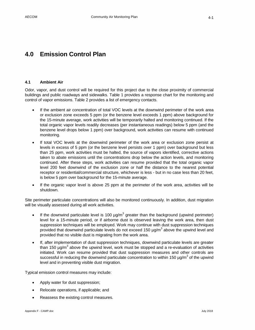
AECOM Community Air Monitoring Plan
Appendix F - CAMP.doc July 2018
4-1
4.0 Emission Control Plan
4.1 Ambient Air
Odor, vapor, and dust control will be required for this project due to the close proximity of commercial buildings and public roadways and sidewalks. Table 1 provides a response chart for the monitoring and control of vapor emissions. Table 2 provides a list of emergency contacts.
• If the ambient air concentration of total VOC levels at the downwind perimeter of the work area or exclusion zone exceeds 5 ppm (or the benzene level exceeds 1 ppm) above background for the 15-minute average, work activities will be temporarily halted and monitoring continued. If the total organic vapor levels readily decreases (per instantaneous readings) below 5 ppm (and the benzene level drops below 1 ppm) over background, work activities can resume with continued monitoring.
• If total VOC levels at the downwind perimeter of the work area or exclusion zone persist at levels in excess of 5 ppm (or the benzene level persists over 1 ppm) over background but less than 25 ppm, work activities must be halted, the source of vapors identified, corrective actions taken to abate emissions until the concentrations drop below the action levels, and monitoring continued. After these steps, work activities can resume provided that the total organic vapor level 200 feet downwind of the exclusion zone or half the distance to the nearest potential receptor or residential/commercial structure, whichever is less - but in no case less than 20 feet, is below 5 ppm over background for the 15-minute average.
• If the organic vapor level is above 25 ppm at the perimeter of the work area, activities will be shutdown.
Site perimeter particulate concentrations will also be monitored continuously. In addition, dust migration will be visually assessed during all work activities.
• If the downwind particulate level is 100 µg/m3 greater than the background (upwind perimeter) level for a 15-minute period, or if airborne dust is observed leaving the work area, then dust suppression techniques will be employed. Work may continue with dust suppression techniques provided that downwind particulate levels do not exceed 150 µg/m3 above the upwind level and provided that no visible dust is migrating from the work area.
• If, after implementation of dust suppression techniques, downwind particulate levels are greater than 150 µg/m3 above the upwind level, work must be stopped and a re-evaluation of activities initiated. Work can resume provided that dust suppression measures and other controls are successful in reducing the downwind particulate concentration to within 150 µg/m3 of the upwind level and in preventing visible dust migration.
Typical emission control measures may include:
• Apply water for dust suppression;
• Relocate operations, if applicable; and
• Reassess the existing control measures.

AECOM Community Air Monitoring Plan
Appendix F - CAMP.doc July 2018
4-2
Figure 4-1 Vapor Emission Response Chart
Continue Work No Yes
Temporarily halt work and allow concentrations to drop
Yes
No Continue Work
Temporarily halt work and initiate emission controls (Re-evaluate controls for dust if emissions controls were previously initiated)
Continue Work No
Yes
Benzene >1 ppm OR
VOCS >5 ppm OR
Dust >100 µg/m3
Benzene >1 ppm OR
VOCS >5 ppm OR
Dust >100 µg/m3
Benzene >1 ppm OR
VOCS >5 ppm OR
Dust >150 µg/m3
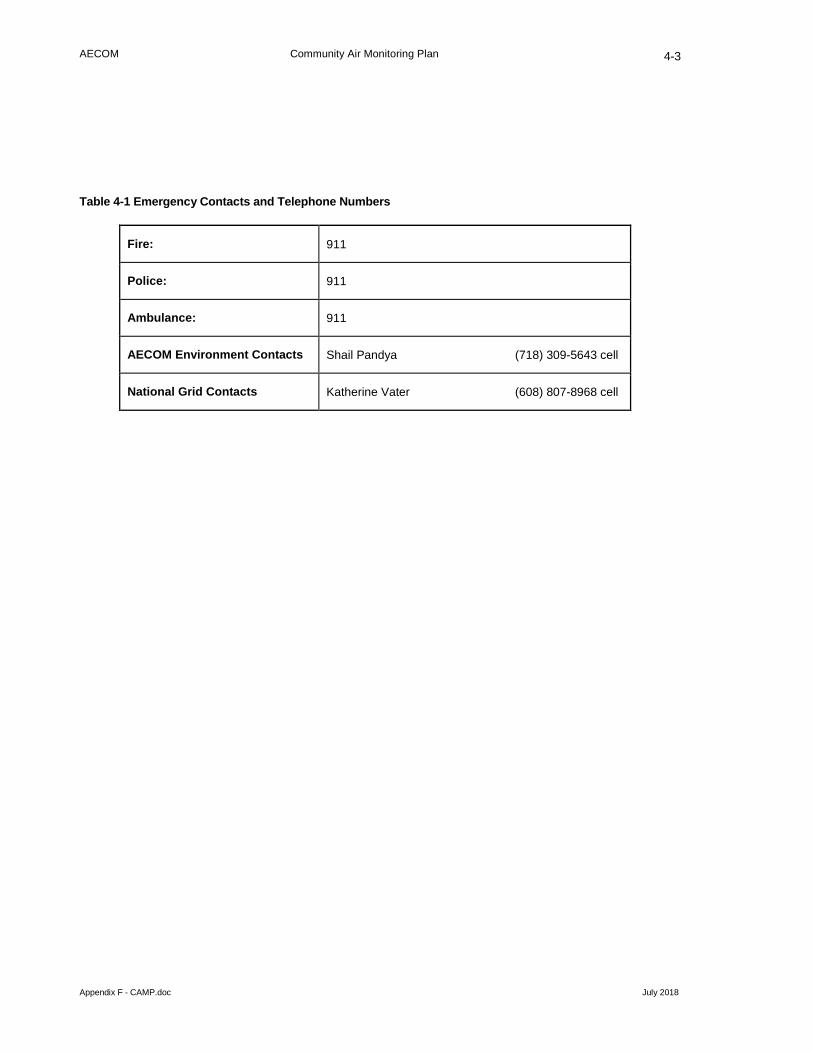
AECOM Community Air Monitoring Plan
Appendix F - CAMP.doc July 2018
4-3
Table 4-1 Emergency Contacts and Telephone Numbers
Fire: 911
Police: 911
Ambulance: 911
AECOM Environment Contacts Shail Pandya (718) 309-5643 cell
National Grid Contacts Katherine Vater (608) 807-8968 cell

AECOM Community Air Monitoring Plan
Appendix F - CAMP.doc July 2018
5-1
5.0 Odor Control Procedures
This section outlines the procedures to be used to control odors that may be generated during ground intrusive activities. The intrusive activities at the Site may generate odors: excavation, test pitting, drilling, utility work, and subsurface soil borings/monitoring well installations. The remainder of this section is intended to provide Site managers, representatives of NYSDEC and New York State Department of Health (NYSDOH), and the public with information summarizing typical odor control options, and to provide some guidance for their implementation. A description of potential sources of odors and methods to be used for odor control is presented in the following sections.
5.1 Potential Sources of Odors
Generally, the residuals encountered at former MGP Sites are well defined. They are related to residual coal tar-like materials and petroleum, and principally contain VOCs, polynuclear aromatic hydrocarbons (PAHs), and a number of inorganic constituents, including metal-complexed cyanide compounds, and metals. Constituents indicative of MGP-related residuals or petroleum products can produce odor emissions during investigation activities when they are unearthed in soil borings/well installations. When this occurs, VOCs and light-end SVOCs can volatilize into the ambient air. Some MGP-related residuals can cause distinctive odors that are similar to mothballs, roofing tar, or asphalt driveway sealer. However, the constituent concentrations generally associated with these odors are typically significantly less than levels that might pose a potential health risk. It is important to note that the CAMP will provide for continual monitoring of VOCs and dust during the fieldwork to monitor for any potential release of constituents which may pose a threat to health.
5.2 Odor Monitoring
The field investigation personnel will record observations of odors generated during the implementation of the subsurface work. When odors attributable to the uncovering of impacted media are generated in the work area during intrusive activities such as excavation or soil borings, observations will also be made at the down-wind limit of the Site, in order to assess the potential for off-site odors. The down-wind odor monitoring will be performed in conjunction with the Site Characterization and dust monitoring program described in this CAMP.
Upon detection of odors at the Site perimeter, Site controls, starting in the work area, will be implemented. The Site controls described in the following sections will be used to assist with odor mitigation to minimize, and to prevent where practicable, the off-site migration of odors. Due to the short distances between any work area at the Site and the property line or nearby potential receptors, Site controls will be implemented proactively when odors are detected in the breathing zone at any work area.
5.3 General Site Controls
Several general excavation or drilling procedure Site controls that will be implemented include:
• Every effort will be made to minimize the amount of time that impacted material is exposed to ambient air at the Site.

AECOM Community Air Monitoring Plan
Appendix F - CAMP.doc July 2018
5-2
• For excavations, it may be possible to move some amount of soil around within the footprint of the excavation in order to minimize the amount of soil removal and subsequent stockpiling of impacted soil at the ground surface. The use of in-excavation stockpiling of excavated soil will be evaluated on a case-by-case basis, and will only be performed with the approval of the NYSDEC field representative, and will be completed only if it does not impede the collection of subsurface soils or the full delineation of the subsurface features being investigated.
• Drill cuttings from the soil borings will be containerized as soon as possible during completion of each soil boring.
• Loading of excavated debris or soil that has been found by the Site manager to be unsuitable material to return to excavation may generate odors. Every effort will be made to complete this work as quickly as possible and to keep these materials covered at all times.
• Meteorological conditions are also a factor in the generation and migration of odors. Some Site activities may be limited to times when specific meteorological conditions prevail, such as when winds are blowing away from a specific receptor.
5.4 Secondary Site Controls
If substantial odors still present an issue following implementation of the above procedures, secondary controls will be enacted. The field representative will work through the applicable list of secondary controls until the perimeter odor issues are resolved. The field representative will work closely with National Grid and NYSDEC during this task, if present. Final selection of controls will be dependent on field conditions encountered. Secondary controls include the following:
• For stockpiled impacted soil, temporary tarps or polyethylene covers will be used to control odors.
• The placement of portable barriers close to small active source areas (excavations) can elevate the discharge point of emissions to facilitate dispersion and minimize the effect on downwind receptors. The barriers can be constructed using materials such as plastic “Jersey barriers”, or fence poles and visual barrier fabric/plastic. The barriers are placed as temporary two or three-sided structures around active excavation or other intrusive areas, oriented such that the barriers are placed on the upwind and downwind sides of the source. If only one side of the source can be accessed, then the barrier should be placed on the downwind side.
• Two agents that can be sprayed over impacted soil have been determined to be effective in controlling emissions. They include odor suppressant solution (BioSolve™), and hydro-mulch. These agents may be used where tarps cannot be effectively deployed over the source material, or where tarps are ineffective in controlling odors:
− BioSolve™ can provide immediate, localized control of odor emissions. Information regarding the preparation and use of BioSolve™ is provided in Appendix A.
− Hydromulch - Although it is unlikely that it will be necessary, a modified hydromulch slurry may be used to cover inactive sources for extended periods of time (up to several days). The hydromulch, typically cellulose fibers (HydroSealR) is modified by mixing a tackifier (glue) with the mulch and water to form a slurry. It is applied using a standard hydroseed applicator to a thickness of ¼ inch. The material forms a sticky, cohesive, and somewhat flexible cover. Reapplication may be necessary if the applied layer becomes desiccated or begins to crack.

AECOM Community Air Monitoring Plan
Appendix F - CAMP.doc July 2018
5-3
5.5 Record Keeping and Communication
Similar to readings recorded during the monitoring specified in the CAMP, all odor monitoring results will be recorded in the field log book or other air monitoring forms, and be available for review by the agencies upon request.
The field representative, in consultation with National Grid, will also provide information on odor monitoring and odor management to residents of the neighborhood should they inquire. In the event that odors persist after these efforts, work will be temporarily discontinued until a mutually agreeable solution with National Grid, NYSDEC, and NYSDOH staff can be worked out which allows the work to be completed while minimizing the off-site transport of nuisance odors.

AECOM Community Air Monitoring Plan
Appendix F - CAMP.doc July 2018
6-1
6.0 Documentation and Reporting
Data generated during perimeter air monitoring will be recorded in field logs and summarized daily in spreadsheets. The electronic measurements from the PIDs and dust meters will be downloaded each day, reviewed, and archived. Exceedances of the action levels, if any, and the actions to be taken to mitigate the situations, will be discussed immediately with the on-site representatives. Summaries of all air monitoring data will be provided to NYSDEC and NYSDOH in electronic format, as requested.

AECOM Community Air Monitoring Plan
Appendix F - CAMP.doc July 2018
Appendix A Vapor Suppression Information

………IIIsss MMMaaakkkiiinnnggg AAA DDDiiiffffffeeerrreeennnccceee!!!
BioSolve® should only be used in accordance with all regulatory rules and regulations. This material is made available or use by professionals or persons having technical skill to be used at the own discretion and risk. These protocols are guidelines only and may need to be modified to site specific conditions. Nothing included herein is a warrantee or to be taken as a license to use BioSolve without the proper permits, approvals, etc. of the appropriate regulatory agencies, nor are the protocols provided as instructions for any specific application of BioSolve.
VAPOR SUPPRESSION / ODOR CONTROL BioSolve® offers a relatively simple and cost effective method of suppressing Odors and VOC release from soils, during excavation, loading, stockpiling, etc. The following guidelines will apply to the most common situations encountered on site. In most cases a 3% BSW solution (1 part BioSolve® concentrate to 33 parts water) will be adequate to keep vapor emissions within acceptable limits and control fugitive odor problems on contact. Although, some sites may only require a 2% solution, up to a 6% solution may be recommended on sites with elevated levels or particularly difficult/ mixed stream contaminants are present. The BioSolve® solution should be applied evenly to the soil surface in sufficient quantity to saturate the surface area. As a general rule, use 1-3 litres of BioSolve® solution to 1 square metre of surface area. (1 gallon of BioSolve® per solution will cover approximately 4-sq. yd. of soil surface area) BioSolve® is a water-based surfactant that will apply like water. BioSolve
®, in its concentrated form, is a viscous liquid material that must be diluted with water. A
fluorescent red tracing dye is present in the formula allowing BioSolve® to be detected during application. Once diluted, BioSolve® can be applied with virtually any equipment that can spray water. BioSolve® will not harm equipment or clog pipes. For large sites, applicators such as water truck, portable agricultural sprayers, foam inductors & pressure sprayers can be used. For smaller jobs, garden sprayers, water extinguishers or a garden hose with a fertiliser attachment on the nozzle can be used effectively. This characteristic makes BioSolve® very adaptable and much most convenient to use in almost any situation. BioSolve® is equally effective when used with all types of water (soft, hard, salt or potable). On stockpiled soil or other soil that will be left undisturbed, a single application of BioSolve® to the exposed surfaces may last up to 10 to 14 days or more (depending on environmental conditions). BioSolve®, when applied, will form a "cap" of clean soil. If the soil is not disturbed, via weather, movement, etc. this "cap" will remain functional. During excavation, loading or other movement of the soil, it may be required to spray an additional amount of BioSolve® to the freshly exposed surface area to keep emissions at an acceptable level. In case of an extremely high level of emissions, or if the soil is heavily contaminated, it may be necessary to increase the strength of the BioSolve® solution or apply more solution per square metre to reduce emissions adequately. It is important that the site be monitored regularly and that the BioSolve® solution be reapplied if and when necessary to insure that VOC emissions and odors remain under control. BioSolve® is packaged and readily available in 55 gallon (208 liter) drums, 5 gallon (19 liter) pails and in 4X1 gallon (3.8 liter X 4) cases. Contact The Westford Chemical Corporation® Toll Free @ 1-800-225-3909, via e-mail at [email protected] or your Local BioSolve distributor for pricing.

BS’101 1 3/16/00
SOIL VAPOR SUPPRESSION UTILIZING BIOSOLVE
BioSolve is being utilized by numerous environmental consultants, response contractors,and fire departments to suppress VOC’s & LEL’s as well as problem odors. BioSolveencapsulates the source of the vapor rather than temporarily blanketing it like a foam orother physical barrier. Vapor reduction is so fast and effective that BioSolve is used tocomply with the tough emission standards regulated by each State.
BioSolve offers a relatively simple and cost effective method of suppressing VOC vaporrelease from soils during excavation, loading, stockpiling… The following guidelines willapply to the most common situations encountered on site.
In most cases a 3% solution of BioSolve will be adequate to keep vapor emissions withinacceptable limits. Dilute BioSolve concentrate with water at a ratio of 1 part BioSolve to33 parts water to make a 3% solution.
The BioSolve solution should be applied evenly to the soil surface in sufficient quantityto dampen the surface well, (as a general rule, 1 gallon of BioSolve solution will coverapproximately 4 sq. yd. of soil surface area). BioSolve is not a foam, it is a surfactantbased product that will apply like water. The solution may be applied with a handsprayer, high pressure power sprayer, water truck, etc., whichever method best suits thesite and/or conditions.
NOTE: In the case of extremely high emission levels and/or very porous soil it may benecessary to increase the strength of the BioSolve solution (6%) or apply more per sq.yd. to reduce emissions adequately. On stockpiled soil or other soil that will beundisturbed, a single application of BioSolve to the exposed surfaces may last 10-14 daysor more. During excavation, loading, or other movement of soil it may be necessary orrequired to spray each freshly exposed surface to keep emissions below acceptable

BS’101 2 3/16/00
levels.It is important that the site be monitored regularly and the BioSolve solution bereapplied if/when necessary to insure that vapor emissions remain at or below acceptablestandards.

----------------------------------------------------------------------------------------------------------------------------------
THE WESTFORD CHEMICAL CORPORATION® Ref. No.: 2001 P.O. Box 798 Date: 1/1/2002 Westford, Massachusetts 01886 USA Phone: (978) 392-0689 Phone: (508) 878-5895 Emergency Phone-24 Hours: 1-800-225-3909
Fax: (978) 692-3487 Web Site: http://www.BioSolve.com E-Mail: [email protected]
---------------------------------------------------------------------------------------------------------------------------------- SECTION I - IDENTITY
Name: BioSolve® CAS #: 138757-63-8 Formula: Proprietary Chemical Family: Water Based, Biodegradable, Wetting Agents & Surfactants HMIS Code: Health 1, Fire 0, Reactivity 0 HMIS Key: 4 = Extreme, 3 = High, 2 = Moderate, 1 = Slight, 0 = Insignificant
---------------------------------------------------------------------------------------------------------------------------------
SECTION II - HAZARDOUS INGREDIENTS Massachusetts Right to Know Law or 29 C.F.R. (Code of Federal Regulations) 1910.1000 require listing of hazardous ingredients.
This product does not contain any hazardous ingredients as defined by CERCLA, Massachusetts Right to Know Law and California's Prop. 65.
---------------------------------------------------------------------------------------------------------------------------------
SECTION III - PHYSICAL - CHEMICAL CHARACTERISTICS
Boiling Point : 265°F Specific Gravity : 1.00 +/-.01 Melting Point : 32°F Vapor Pressure mm/Hg : Not Applicable Surface Tension- 6% Solution
: 29.1 Dyne/cm at 25°C Vapor Density Air = 1 : Not Applicable
Reactivity with Water : No Viscosity - Concentrate : 490 Centipoise Evaporation Rate : >1 as compared to Water Viscosity - 6% Solution : 15 Centipoise Appearance : Clear Liquid unless Dyed Solubility in Water : Complete Odor : Pleasant Fragrance pH : 9.1+/-.3 Pounds per Gallon : 8.38
----------------------------------------------------------------------------------------------------------------------------------
SECTION IV - FIRE AND EXPLOSION DATA
Special Fire Fighting Procedures : None Flammable Limit : None Unusual Fire and Explosion Hazards : None Auto Ignite Temperature : None Solvent for Clean-Up : Water Fire Extinguisher Media : Not Applicable Flash Point : None
PAGE 1 OF 2

Date:1/1/2002 MSDS Ref. No. 2001 BioSolve®
SECTION V - SPECIAL PRECAUTIONS AND SPILL/LEAK PROCEDURES
Precautions to be taken in Handling and Storage: Use good normal hygiene. Precautions to be taken in case of Spill or Leak - Small spills, in an undiluted form, contain. Soak up with absorbent materials. Large spills, in an undiluted form, dike and contain. Remove with vacuum truck or pump to storage/salvage vessel. Soak up residue with absorbent materials. Waste Disposal Procedures - Dispose in an approved disposal area or in a manner which complies with all local, state, and federal regulations.
----------------------------------------------------------------------------------------------------------------------------------
SECTION VI - HEALTH HAZARDS
Threshold Limit Values: Not applicable Signs and Symptoms of Over Exposure- Acute : Moderate eye irritation. Skin: Causes redness, edema, drying of skin. Chronic: Pre-existing skin and eye disorders may be aggravated by contact with this product. Medical Conditions Generally Aggravated by Exposure: Unknown Carcinogen: No Emergency First Aid Procedures - Eyes: Flush thoroughly with water for 15 minutes. Get medical attention. Skin: Remove contaminated clothing. Wash exposed areas with soap and water. Wash clothing before reuse. Get medical attention if irritation develops. Ingestion: Get medical attention. Inhalation: None considered necessary.
----------------------------------------------------------------------------------------------------------------------------------
SECTION VII - SPECIAL PROTECTION INFORMATION Respiratory Protection
: Not necessary
Local Exhaust Required
: No
Ventilation Required
: Normal Protective Clothing : Gloves, safety glasses Wash clothing before reuse.
----------------------------------------------------------------------------------------------------------------------------------
SECTION VIII - PHYSICAL HAZARDS
Stability : Stable Incompatible Substances : None Known Polymerization : No Hazardous Decomposition Products : None Known
----------------------------------------------------------------------------------------------------------------------------------
SECTION IX - TRANSPORT & STORAGE
DOT Class : Not Regulated/Non Hazardous Freeze Temperature : 28°F Storage : 35°F-120°F Freeze Harm : None (thaw & stir) Shelf Life : Unlimited Unopened
----------------------------------------------------------------------------------------------------------------------------------
SECTION X - REGULATORY INFORMATION
The Information on this Material Safety Data Sheet reflects the latest information and data that we have on hazards, properties, and handling of this product under the recommended conditions of use. Any use of this product or method of application, which is not described on the Product label or in this Material Safety Data Sheet, is the sole responsibility of the user. This Material Safety Data Sheet was prepared to comply with the OSHA Hazardous Communication Regulation and Massachusetts Right to Know Law.
PAGE 2 OF 2