siti norafida jusoh*, hisham mohamad, aminaton marto & nor
TRANSCRIPT
Malaysian Journal of Civil Engineering 27 Special Issue (1):81-92 (2015)
All rights reserved. No part of contents of this paper may be reproduced or transmitted in any form or by any means
without the written permission of Faculty of Civil Engineering, Universiti Teknologi Malaysia
POINT LOAD TESTING OF FLEXURAL BEHAVIOR OF SEGMENTED
TUNNEL LINING
Siti Norafida Jusoh*, Hisham Mohamad, Aminaton Marto & Nor
Zurairahetty Mohd Yunus
Department of Geotechnics & Transportation, Faculty of Civil Engineering, Universiti Teknologi
Malaysia, 81310 Skudai, Johor Bahru, Malaysia
*Corresponding Author: [email protected]
Abstract: In tunnel, design of precast tunnel lining are not merely about the strength, but how
much its allow to move to account the deflection comes from movement of surrounding soil and
load. Thus, the design of tunnel lining is not straight forward. Understanding the flexural
behavior of segmented lining is a bonus to optimize design lining in cost effective way. Tunnel
lining are designed in segment and have joint that allows tunnel to become flexural and allow
deformation taken by the lining load carrying capacity. The objective of this paper is to present
some of the research works on segmented tunnel lining conducted in the laboratory. A series of
laboratory testing of point load test have been developed to imitate behavior of segmental tunnel
lining condition in real. Two types of support system were introduced namely pin-pin and pin-
roller condition to imitate both rigid and hinge condition of lining. Support mechanisms of pin-
roller support condition shows variation trend in stress-strain and moment readings and
meanwhile for pin-pin it show mirror trend for both result. High stiffness of lining is important at
the edge of segment.
Keywords: Tunnel; segment lining; point load test; laboratory; flexural
1.0 Introduction
Tunnel just laid in the excavated bed soil where lining is allowed to move.
Lining also induces bending moment both in negative and positive bending
moment simultaneously. The proper criterion for judging lining behavior is
therefore not adequate strength to resist bending stresses, but adequate ductility
to conform to imposed deformations. In short, the lining is a confined flexible
ring. Lining cannot fail in flexure – unless there is unfilled void, or exceedingly
soft surrounding medium, behind the lining. Design of tunnel lining is not
independent structural problem, but a ground-structure interaction problem, with
82 Malaysian Journal of Civil Engineering 27 Special Issue (1): 81-92 (2015)
the emphasis on the ground (Bickel, 1996). Thus, bending moment in tunnel
lining is not a straight forward prediction.
Considerable research on movement and stresses for a single and multiple
tunnels has been undertaken (Peck, 1964; Sagaseta, 1987; Verruijt and Booker,
1996; Louganathan and Poulos, 1998; Park, 2004; Kim, 1996; Blom et al, 1999;
Karakus and Fowell, 2005; and Moeller, 2006). However, lack of investigation
exists for extreme details conditions of structural response (i.e., flexural bending
moment in tunnel lining) especially in longitudinal seam. The soil stiffness, the
rigidity of lining, the interaction of soil-lining and response of joint mechanism
were included factors that should be taking into account in bending moment
investigation to achieve a perfect prediction. Blom et al. (1999) and Cavalaro et
al. (2011) previously both carried out research on circumferential seam behavior.
Blom et al. (1999) found out that changes in stress distribution occurred in a ring
of segment. Circumferential seam of lining were comfortable to analyses and
quite easily to understand their behavior but different manner investigation need
for longitudinal seam. Both concluded that longitudinal joint is crucial to
investigate but complex analysis to fulfill (Blom et al., 1999 and Cavalaro et al.,
2011).
Recently, Teachavorasinskun & Chub-uppakarn (2010) and Arnau and Molins
(2011) had carried out research on the longitudinal seam behavior.
Teachavorasinskun & Chub-uppakarn (2010) focus on load and displacement in
jointed two segmented lining applied with two point load test in laboratory. They
validated their partial-scale laboratory lab with FEM and learned that an angular
joint stiffness is in range of 1000-3000 kNm/rad could be adopted for joints to be
incorporated in the flexural moment calculations. Meanwhile Arnau and Molins
(2011) validated in-situ full-scale testing of slender tunnel of new Line 9 (L9) of
the metro of Barcelona with FEM simulations. Nonlinear stress occurred in
lining. In general, tensile stresses yield at extrados and compression stresses
depicted at intrados of lining. Those stresses trend change when there are
concentrated load applied at specific position. This agreed with theoretical
bending moment behavior in tunnel where tunnel bulge outward and inward to
react with surrounding soil affect.
This research is focusing on bending moment of lining as to gain benefit from
designing the lining in more cost effective way. In parallel, it is important to
determine the safety measurement of bearing capacity of lining to withstand soil
surrounding and additional unexpected range of future external loading for
lining. Intensive review on previous flexural test on tunnel had been carried out
Malaysian Journal of Civil Engineering 27 Special Issue (1): 81-92 (2015) 83
to construct perfect test arrangement for our specimens. Ideas of testing
arrangement especially designing the support mechanisms have been developed.
In this paper, research works regarding the developed segmented tunnel lining
testing were presented. A series of laboratory testing of point load test have been
developed to imitate flexural behavior of segmental tunnel lining condition in
real. Two types of support system were introduced namely pin-pin and pin-roller
condition. Pin-pin used to imitate rigid tunnel meanwhile hinge condition of
lining were represented with pin-roller support.
2.0 Development of Model Experiments
Flexural bending test using an appropriate hogging segment taken from nearby
factory has been carried out. Laboratory testing of single segmental lining and
dual jointed tunnel lining tests were conducted. Testing had been done in 4
different phases with one segment and dual jointed of halves of segment using
pin-pin support and pin-roller support to simulate tunnel behavior. In particular,
testing was carried out to analyses the complex lining joint behavior in
longitudinal joint circumstances and to understand the structure respond with
more certainty. Initial simulation of three dimensional of one segment and two
jointed segment firstly carried out before proceed the experiment base. Support
mechanisms were designated at first place to resemble the real joint behavior in
lining. Two support mechanisms are introduce namely; Pin-Pin support (Phase 1
and 3) and followed by Pin-Roller support (Phase 2 and 4). This paper discussed
the single segment testing results of Phase 1 and Phase 2 only.
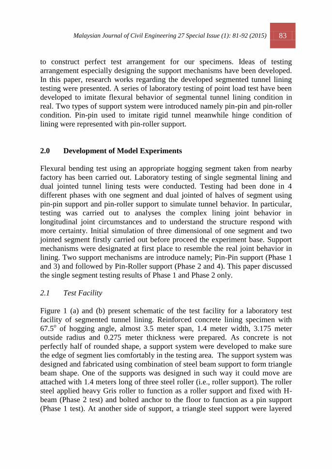
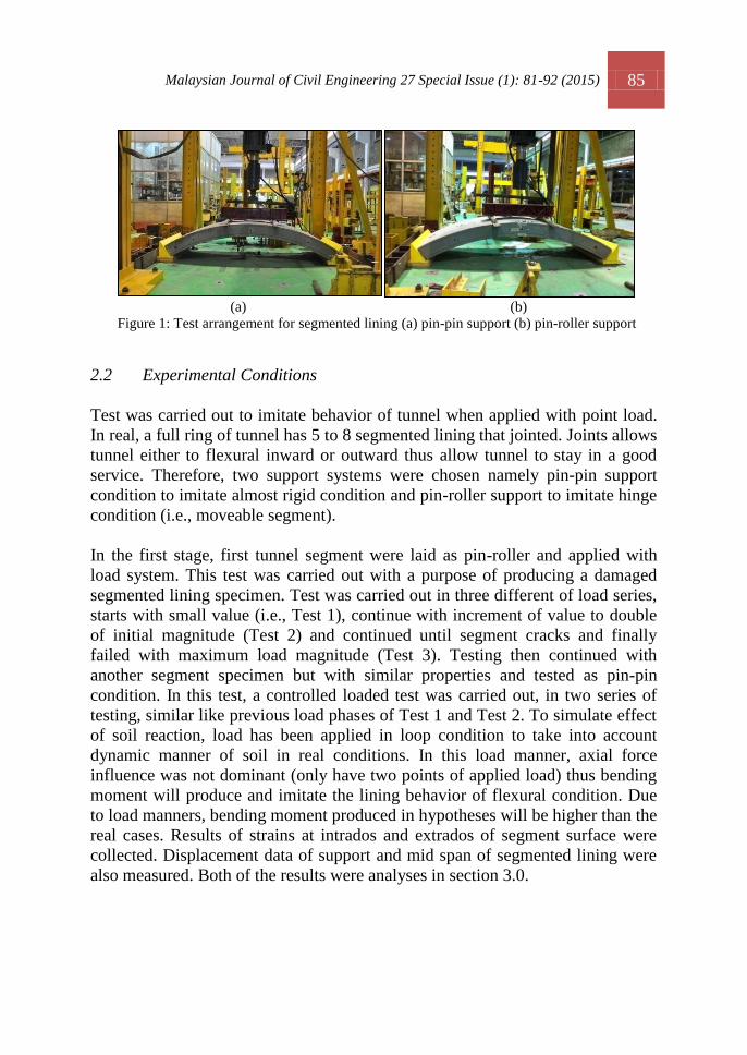
2.1 Test Facility
Figure 1 (a) and (b) present schematic of the test facility for a laboratory test
facility of segmented tunnel lining. Reinforced concrete lining specimen with
67.5o of hogging angle, almost 3.5 meter span, 1.4 meter width, 3.175 meter
outside radius and 0.275 meter thickness were prepared. As concrete is not
perfectly half of rounded shape, a support system were developed to make sure
the edge of segment lies comfortably in the testing area. The support system was
designed and fabricated using combination of steel beam support to form triangle
beam shape. One of the supports was designed in such way it could move are
attached with 1.4 meters long of three steel roller (i.e., roller support). The roller
steel applied heavy Gris roller to function as a roller support and fixed with H-
beam (Phase 2 test) and bolted anchor to the floor to function as a pin support
(Phase 1 test). At another side of support, a triangle steel support were layered
84 Malaysian Journal of Civil Engineering 27 Special Issue (1): 81-92 (2015)
with 18mm x 350 x 1500 x 5 pieces plywood and hold by boxes of steel box
with 2m anchored steel bolted to the laboratory floor (i.e., pin support). The
triangle steel beam also supported laterally with H-beams. This support system
was expected to minimize the triangular beam translation during the testing. To
attach segment to the triangle steel beam, wall plug of 220mm length and 50mm
thread with diameter of 25mm were specially designed to help fixed the segment
in position to the hole of triangle steel beam support system.
Testing was carried out with a designed loading system. Axial load, imitating the
ground static load was applied vertically to the middle of load system. The load
from hydraulic ram system was performed using load controlled system. The
servo-hydraulic ram had their own load cell. Another load cell was laid below
the load hydraulic load ram to double check the load applied to the segment.
Frame system help to distribute loading. Distribution mechanisms of load
system consist of load cell, layered of steel, boxes of steel and two pieces of
long steel arranged accordingly so the load are distributed symmetrically at both
side of segment longitudinally. 200 tan of load cell are attached with
computerized system used to verify the applied load from hydraulic ram of
Dartec system.
The strain gauges were properly mounted onto test specimen both extrados and
intrados of segment. It is important that strain is accurately measured transferred
from the test specimen, through the adhesive and the strain gage backing to the
foil themselves. Strains data were measured for every load step. LVDTs were
mounted at possible higher movement place. Two LVDTs were used to measure
the vertical displacement occur in the mid span of segment when applied with
load. Translation readings and displacement readings were also being monitored
at the support system. One LVDT is placed at roller support side to measure
movement of segment. Two more LVDTS, both mounted at pin support side;
one placed at opposite direction of triangular steel beam to measure movement if
any and another is mounted to the bottom of triangular steel beam(that layered
with plywood) to measure any downward movement of the support.
Malaysian Journal of Civil Engineering 27 Special Issue (1): 81-92 (2015) 85
(a) (b)
Figure 1: Test arrangement for segmented lining (a) pin-pin support (b) pin-roller support
2.2 Experimental Conditions
Test was carried out to imitate behavior of tunnel when applied with point load.
In real, a full ring of tunnel has 5 to 8 segmented lining that jointed. Joints allows
tunnel either to flexural inward or outward thus allow tunnel to stay in a good
service. Therefore, two support systems were chosen namely pin-pin support
condition to imitate almost rigid condition and pin-roller support to imitate hinge
condition (i.e., moveable segment).
In the first stage, first tunnel segment were laid as pin-roller and applied with
load system. This test was carried out with a purpose of producing a damaged
segmented lining specimen. Test was carried out in three different of load series,
starts with small value (i.e., Test 1), continue with increment of value to double
of initial magnitude (Test 2) and continued until segment cracks and finally
failed with maximum load magnitude (Test 3). Testing then continued with
another segment specimen but with similar properties and tested as pin-pin
condition. In this test, a controlled loaded test was carried out, in two series of
testing, similar like previous load phases of Test 1 and Test 2. To simulate effect
of soil reaction, load has been applied in loop condition to take into account
dynamic manner of soil in real conditions. In this load manner, axial force
influence was not dominant (only have two points of applied load) thus bending
moment will produce and imitate the lining behavior of flexural condition. Due
to load manners, bending moment produced in hypotheses will be higher than the
real cases. Results of strains at intrados and extrados of segment surface were
collected. Displacement data of support and mid span of segmented lining were
also measured. Both of the results were analyses in section 3.0.
86 Malaysian Journal of Civil Engineering 27 Special Issue (1): 81-92 (2015)
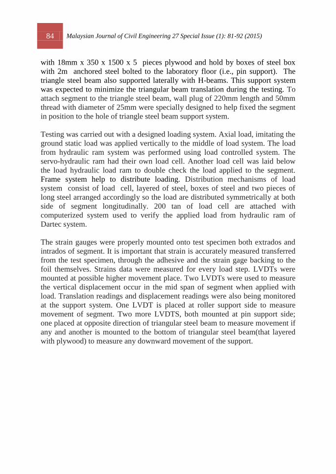
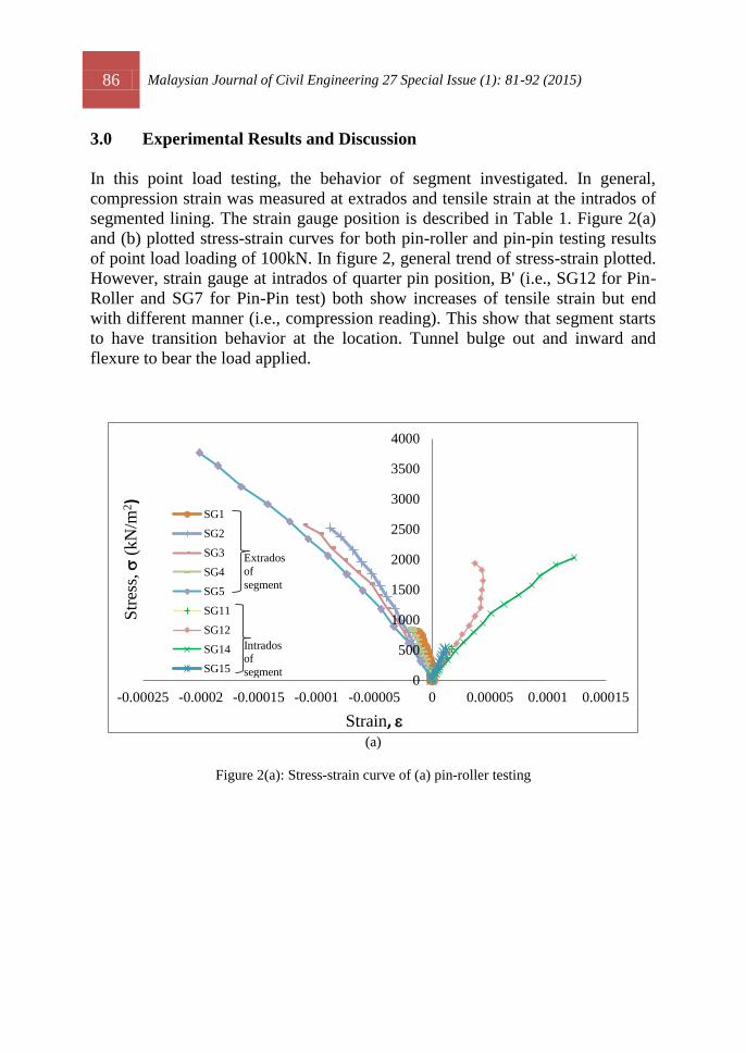
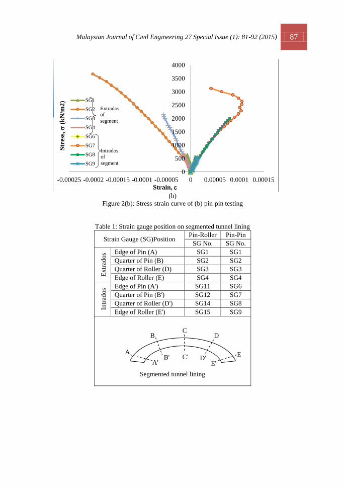
3.0 Experimental Results and Discussion
In this point load testing, the behavior of segment investigated. In general,
compression strain was measured at extrados and tensile strain at the intrados of
segmented lining. The strain gauge position is described in Table 1. Figure 2(a)
and (b) plotted stress-strain curves for both pin-roller and pin-pin testing results
of point load loading of 100kN. In figure 2, general trend of stress-strain plotted.
However, strain gauge at intrados of quarter pin position, B' (i.e., SG12 for Pin-
Roller and SG7 for Pin-Pin test) both show increases of tensile strain but end
with different manner (i.e., compression reading). This show that segment starts
to have transition behavior at the location. Tunnel bulge out and inward and
flexure to bear the load applied.
(a)
Figure 2(a): Stress-strain curve of (a) pin-roller testing
0
500
1000
1500
2000
2500
3000
3500
4000
-0.00025 -0.0002 -0.00015 -0.0001 -0.00005 0 0.00005 0.0001 0.00015
Str
ess,
s (
kN
/m2)
Strain, e
SG1
SG2
SG3
SG4
SG5
SG11
SG12
SG14
SG15
Extrados
of
segment
Intrados of
segment
Malaysian Journal of Civil Engineering 27 Special Issue (1): 81-92 (2015) 87
(b)
Figure 2(b): Stress-strain curve of (b) pin-pin testing
Table 1: Strain gauge position on segmented tunnel lining
Strain Gauge (SG)Position Pin-Roller Pin-Pin
SG No. SG No.
Ex
trad
os Edge of Pin (A) SG1 SG1
Quarter of Pin (B) SG2 SG2
Quarter of Roller (D) SG3 SG3
Edge of Roller (E) SG4 SG4
Intr
ado
s Edge of Pin (A') SG11 SG6
Quarter of Pin (B') SG12 SG7
Quarter of Roller (D') SG14 SG8
Edge of Roller (E') SG15 SG9
Segmented tunnel lining
0
500
1000
1500
2000
2500
3000
3500
4000
-0.00025 -0.0002 -0.00015 -0.0001 -0.00005 0 0.00005 0.0001 0.00015
Str
ess,
s (
kN
/m2
)
Strain, e
SG1
SG2
SG3
SG4
SG6
SG7
SG8
SG9
A
B D
E
C
A' B' C' D'
E'
Intrados of
segment
Extrados of
segment
88 Malaysian Journal of Civil Engineering 27 Special Issue (1): 81-92 (2015)
(a) (b)
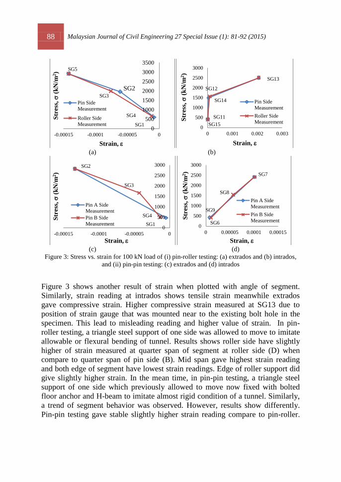
(c) (d)
Figure 3: Stress vs. strain for 100 kN load of (i) pin-roller testing: (a) extrados and (b) intrados,
and (ii) pin-pin testing: (c) extrados and (d) intrados
Figure 3 shows another result of strain when plotted with angle of segment.
Similarly, strain reading at intrados shows tensile strain meanwhile extrados
gave compressive strain. Higher compressive strain measured at SG13 due to
position of strain gauge that was mounted near to the existing bolt hole in the
specimen. This lead to misleading reading and higher value of strain. In pin-
roller testing, a triangle steel support of one side was allowed to move to imitate
allowable or flexural bending of tunnel. Results shows roller side have slightly
higher of strain measured at quarter span of segment at roller side (D) when
compare to quarter span of pin side (B). Mid span gave highest strain reading
and both edge of segment have lowest strain readings. Edge of roller support did
give slightly higher strain. In the mean time, in pin-pin testing, a triangle steel
support of one side which previously allowed to move now fixed with bolted
floor anchor and H-beam to imitate almost rigid condition of a tunnel. Similarly,
a trend of segment behavior was observed. However, results show differently.
Pin-pin testing gave stable slightly higher strain reading compare to pin-roller.
0
500
1000
1500
2000
2500
3000
3500
-0.00015 -0.0001 -0.00005 0
Str
ess,
s (
kN
/m2)
Strain, e
Pin Side
Measurement
Roller Side
Measurement
SG5
SG2
SG1
SG4
SG3
0
500
1000
1500
2000
2500
3000
0 0.001 0.002 0.003
Str
ess,
s (
kN
/m2)
Strain, e
Pin Side
Measurement
Roller Side
Measurement
SG12
SG14
SG15
SG11
SG13
0
500
1000
1500
2000
2500
3000
-0.00015 -0.0001 -0.00005 0
Str
ess,
s (
kN
/m2)
Strain, e
Pin A Side
Measurement
Pin B Side
Measurement
SG2
SG4
SG1
SG3
0
500
1000
1500
2000
2500
3000
0 0.00005 0.0001 0.00015
Str
ess,
s (
kN
/m2)
Strain, e
Pin A Side
Measurement
Pin B Side
Measurement
SG9
SG7
SG6
SG8
Malaysian Journal of Civil Engineering 27 Special Issue (1): 81-92 (2015) 89
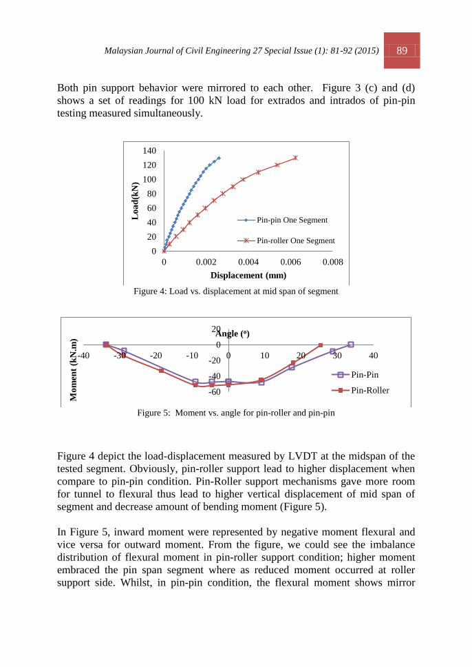
Both pin support behavior were mirrored to each other. Figure 3 (c) and (d)
shows a set of readings for 100 kN load for extrados and intrados of pin-pin
testing measured simultaneously.
Figure 4: Load vs. displacement at mid span of segment
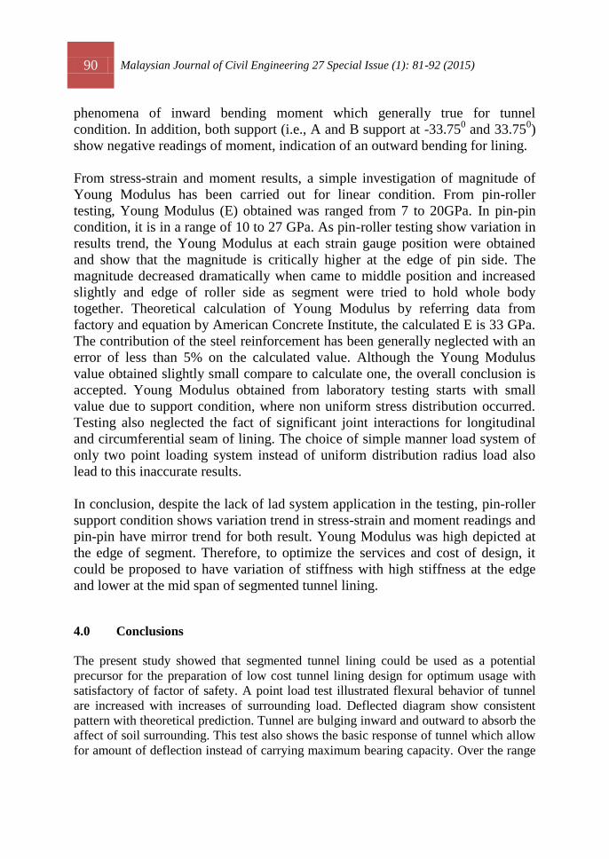
Figure 5: Moment vs. angle for pin-roller and pin-pin
Figure 4 depict the load-displacement measured by LVDT at the midspan of the
tested segment. Obviously, pin-roller support lead to higher displacement when
compare to pin-pin condition. Pin-Roller support mechanisms gave more room
for tunnel to flexural thus lead to higher vertical displacement of mid span of
segment and decrease amount of bending moment (Figure 5).
In Figure 5, inward moment were represented by negative moment flexural and
vice versa for outward moment. From the figure, we could see the imbalance
distribution of flexural moment in pin-roller support condition; higher moment
embraced the pin span segment where as reduced moment occurred at roller
support side. Whilst, in pin-pin condition, the flexural moment shows mirror
0
20
40
60
80
100
120
140
0 0.002 0.004 0.006 0.008
Lo
ad
(kN
)
Displacement (mm)
Pin-pin One Segment
Pin-roller One Segment
-60
-40
-20
0
20
-40 -30 -20 -10 0 10 20 30 40
Mo
men
t (k
N.m
)
Angle (o)
Pin-Pin
Pin-Roller
90 Malaysian Journal of Civil Engineering 27 Special Issue (1): 81-92 (2015)
phenomena of inward bending moment which generally true for tunnel
condition. In addition, both support (i.e., A and B support at -33.750 and 33.75
0)
show negative readings of moment, indication of an outward bending for lining.
From stress-strain and moment results, a simple investigation of magnitude of
Young Modulus has been carried out for linear condition. From pin-roller
testing, Young Modulus (E) obtained was ranged from 7 to 20GPa. In pin-pin
condition, it is in a range of 10 to 27 GPa. As pin-roller testing show variation in
results trend, the Young Modulus at each strain gauge position were obtained
and show that the magnitude is critically higher at the edge of pin side. The
magnitude decreased dramatically when came to middle position and increased
slightly and edge of roller side as segment were tried to hold whole body
together. Theoretical calculation of Young Modulus by referring data from
factory and equation by American Concrete Institute, the calculated E is 33 GPa.
The contribution of the steel reinforcement has been generally neglected with an
error of less than 5% on the calculated value. Although the Young Modulus
value obtained slightly small compare to calculate one, the overall conclusion is
accepted. Young Modulus obtained from laboratory testing starts with small
value due to support condition, where non uniform stress distribution occurred.
Testing also neglected the fact of significant joint interactions for longitudinal
and circumferential seam of lining. The choice of simple manner load system of
only two point loading system instead of uniform distribution radius load also
lead to this inaccurate results.
In conclusion, despite the lack of lad system application in the testing, pin-roller
support condition shows variation trend in stress-strain and moment readings and
pin-pin have mirror trend for both result. Young Modulus was high depicted at
the edge of segment. Therefore, to optimize the services and cost of design, it
could be proposed to have variation of stiffness with high stiffness at the edge
and lower at the mid span of segmented tunnel lining.
4.0 Conclusions
The present study showed that segmented tunnel lining could be used as a potential
precursor for the preparation of low cost tunnel lining design for optimum usage with
satisfactory of factor of safety. A point load test illustrated flexural behavior of tunnel
are increased with increases of surrounding load. Deflected diagram show consistent
pattern with theoretical prediction. Tunnel are bulging inward and outward to absorb the
affect of soil surrounding. This test also shows the basic response of tunnel which allow
for amount of deflection instead of carrying maximum bearing capacity. Over the range
Malaysian Journal of Civil Engineering 27 Special Issue (1): 81-92 (2015) 91
of applied load studied, the maximum point load could be taken by single segmented
lining is 420 kN. Support mechanisms of pin-roller support condition shows
variation trend in stress-strain and moment readings and meanwhile for pin-pin it
show mirror trend for both result. High stiffness of lining is only important at the
edge of segmented lining, thus the design of the lining could be revised. The
experimental results revealed that the flexural segmented tunnel lining design could be
guidance to design the tunnel effectively in future.
5.0 Acknowledgements
This research was possible thanks to the support provided by MTD ACPI Engineering
Berhad responsible of the design and supplying segment tunnel for Construction and
Completion of Beduk Reservoir and Tunnels for Downtown Line Stage 3. First author
also wants to thank the support of the University and Research Commissioner of the
Exploratory Research Grant Scheme (ERGS).
6.0 Appendix A
In order to obtain Young Modulus, E value, American Concrete Institute (ACI)
has draw the equation of:
or (Eq. 1)
where
fc' =compressive strength of concrete at 28 days (psi)
From factory, we knew, compressive strength of concrete, fc is = 42.8 N/mm2 so
that, fc' = 6990.82 psi
E = = 4765834.05 psi
converting the value into SI units,
E = 32859268 kN/m2 = 33 GPa.
92 Malaysian Journal of Civil Engineering 27 Special Issue (1): 81-92 (2015)
References
Arnau, O., and Molins, C. (2011). Experimental and analytical study of the structural response of
segmental tunnel linings based on an in situ loading test. Part 2: Numerical simulation,
Tunnelling and Underground Space Technology 26, 778–788.
Blom, C.B.M., van der Horst, E.J., Jovanovic, P.S., 1999. Three-dimensional structural analyses
of the shield-driven ‘Green Heart’ tunnel of the High-Speed Line South. Tunn. Undergr.
Space Technol. 14 (2), 217–224.
Bickel, J.O., Kuessel, T.R., King, E.H. (1996). Soft Ground tunnel support and lining. Tunnel
Engineering Handbook; 2nd
Edition, Chapman and Hall, New York.
Caratelli, A., Meda, A., Rinaldi, Z., Romualdi, P., (2011). Structural behaviour of precast tunnel
segments in fiber reinforced concrete, Tunnelling and Underground Space Technology 26,
284–291.
Cavalaro, S.H.P., Blom, C.B.M., Walrave, J.C., Aguado, A., (2011). Structural analysis of
contact deficiencies in segmented lining. Tunnelling and Underground Space Technology 26,
734–749.
Chen, J., Mo, H., 2009. Numerical study on crack problems in segments of shield tunnel using
finite element method. Tunn. Undergr. Space Technol. 24 (1), 91–102.
Hudoba, I., (1997). Contribution to Static Analysis of Load-bearing Concrete Tunnel Lining
Shield-driven Technology Built by Shield-driven Technology. Tunnelling and
Underground Space Technology, Vol. 12, No. 1, pp. 55-58.
Koyama, Y., (2003). Present status and technology of shield tunneling method in Japan.
Tunneling and Underground Space Technology 18, 145–159.
Liao, S.M., Peng, F.E. & Shen, S.L. (2008). Analysis of Shearing effect on tunnel induced by
load transfer. Tunnel and Underground Space Technology 23, 421-430.
Loganathan, N., and Poulos, H.G., (1996). Analytical Prediction for Tunneling-Induced Ground
Movements in Clays, Journal of Geotechnical and Geoenvironmental Engineering Vol. 124,
N0. 9, 846-856.
Mo, H.H and Chen, J.S., (2008). Study on inner force and dislocation of segments caused by
shield machine attitude, Tunnelling and Underground Space Technology 23, 281–291.
Nishikawa. K, (2003). Development of a prestressed and precast concrete segmental lining,
Tunnelling and Underground Space Technology 18, 243–251
Park, K.H., (2004). Elastic Solution for Tunneling-Induced Ground Movements in Clays,
International Journal of Geomechanics 4:4(310)
Sagaseta, C. (1987). Analysis of undrained soil deformation due to ground loss,
Geotechnique 37, No. 3,301-320 .
Sugimoto, M. (2006). Causes of Shield Segment Damages During Construction, International
Symposium on Underground Excavation and Tunnelling
Teachavorasinskun & Chub-uppakarn (2010). Influence of segmental joints on tunnel lining.
Tunneling and Underground Space Technology 25, 490–494
Verruijt, A. & Booker, J. R. (1996). Surface settlements due to deformation of a tunnel in an
elastic half plane, Geotechnique 46, No. 4, 753±756.
Wang, L.Z., Wang, Z., Ling-ling Li, L.L., & Wang, J.C., (2011). Construction behavior
simulation of a hydraulic tunnel during standpipe lifting. Tunneling and Underground Space
Technology 26, 674–685.
Wang , L.Z., Li, L.L., Lv, X-J.(2009). Complex Variable Solutions for Tunneling-Induced
Ground Movement, International Journal of Geomechanics 9:2(63)