sitrans f m mag 8000 modbus rtu - siemens ag · sitrans f electromagnetic flowmeters communication...
TRANSCRIPT

SITRANS F
Electromagnetic FlowmetersCommunication ModulesSITRANS F M MAG 8000 Modbus RTU
Operating Instructions • 08/2011


1 Introduction
2
Safety notes
3
Hardware Installation
SITRANS F
4
Connecting
Communication ModulesSITRANS F M MAG 8000 Modbus RTU
5
System integration
6
Function codes Operating Instructions
7
Technical data
A
Modbus holding registers
B
Appendix
Add-on module for use with flowmeter types SITRANS F M MAG 8000
08/2011 A5E03409989-01
Legal information Warning notice system
This manual contains notices you have to observe in order to ensure your personal safety, as well as to prevent damage to property. The notices referring to your personal safety are highlighted in the manual by a safety alert symbol, notices referring only to property damage have no safety alert symbol. These notices shown below are graded according to the degree of danger.
DANGER indicates that death or severe personal injury will result if proper precautions are not taken.
WARNING indicates that death or severe personal injury may result if proper precautions are not taken.
CAUTION with a safety alert symbol, indicates that minor personal injury can result if proper precautions are not taken.
CAUTION without a safety alert symbol, indicates that property damage can result if proper precautions are not taken.
NOTICE indicates that an unintended result or situation can occur if the relevant information is not taken into account.
If more than one degree of danger is present, the warning notice representing the highest degree of danger will be used. A notice warning of injury to persons with a safety alert symbol may also include a warning relating to property damage.
Qualified Personnel The product/system described in this documentation may be operated only by personnel qualified for the specific task in accordance with the relevant documentation, in particular its warning notices and safety instructions. Qualified personnel are those who, based on their training and experience, are capable of identifying risks and avoiding potential hazards when working with these products/systems.
Proper use of Siemens products Note the following:
WARNING Siemens products may only be used for the applications described in the catalog and in the relevant technical documentation. If products and components from other manufacturers are used, these must be recommended or approved by Siemens. Proper transport, storage, installation, assembly, commissioning, operation and maintenance are required to ensure that the products operate safely and without any problems. The permissible ambient conditions must be complied with. The information in the relevant documentation must be observed.
Trademarks All names identified by ® are registered trademarks of Siemens AG. The remaining trademarks in this publication may be trademarks whose use by third parties for their own purposes could violate the rights of the owner.
Disclaimer of Liability We have reviewed the contents of this publication to ensure consistency with the hardware and software described. Since variance cannot be precluded entirely, we cannot guarantee full consistency. However, the information in this publication is reviewed regularly and any necessary corrections are included in subsequent editions.
Siemens AG Order number: A5E03409989 Copyright © Siemens AG 2011. Industry Sector Ⓟ 08/2011 Technical data subject to changePostfach 48 48 90026 NÜRNBERG GERMANY

SITRANS F M MAG 8000 Modbus RTU Operating Instructions, 08/2011, A5E03409989-01 3
Table of contents
1 Introduction................................................................................................................................................ 5
1.1 Document history ...........................................................................................................................5
1.2 Modbus RTU technology ...............................................................................................................6
1.3 Further Information ........................................................................................................................8
2 Safety notes............................................................................................................................................... 9
2.1 Installation in hazardous area........................................................................................................9
3 Hardware Installation ............................................................................................................................... 11
4 Connecting .............................................................................................................................................. 13
4.1 Wiring ...........................................................................................................................................13
4.2 Closing the device........................................................................................................................15
5 System integration ................................................................................................................................... 17
5.1 System integration instructions....................................................................................................17
5.2 Function check.............................................................................................................................17
5.3 Communication parameter settings .............................................................................................18
5.4 Parameter access ........................................................................................................................18
5.5 Commissioning with PDM............................................................................................................19 5.5.1 General instructions .....................................................................................................................19 5.5.2 Commissioning steps...................................................................................................................19 5.5.3 Installing EDD files.......................................................................................................................20 5.5.4 Adding device to network.............................................................................................................21 5.5.5 Configuring the device .................................................................................................................22 5.5.6 Operation .....................................................................................................................................24
6 Function codes ........................................................................................................................................ 25
6.1 Modbus Commands.....................................................................................................................25
6.2 Read coils ....................................................................................................................................26
6.3 Read multiple registers ................................................................................................................28
6.4 Write single coil ............................................................................................................................30
6.5 Write multiple registers ................................................................................................................31
6.6 Report slave ID command ...........................................................................................................34
6.7 Exception handling.......................................................................................................................35
7 Technical data ......................................................................................................................................... 37

Table of contents
SITRANS F M MAG 8000 Modbus RTU 4 Operating Instructions, 08/2011, A5E03409989-01
A Modbus holding registers......................................................................................................................... 39
A.1 Introduction to holding registers.................................................................................................. 39
A.2 MODBUS application settings..................................................................................................... 40
A.3 MODBUS driver settings ............................................................................................................. 41
A.4 Menu control ............................................................................................................................... 42
A.5 Sensor characteristics................................................................................................................. 43
A.6 Totalization.................................................................................................................................. 45
A.7 Pulse output ................................................................................................................................ 45
A.8 Service control ............................................................................................................................ 47
A.9 Error messages........................................................................................................................... 47
A.10 Power control .............................................................................................................................. 53
A.11 Consumption statistic .................................................................................................................. 55
A.12 Consumption profile .................................................................................................................... 56
A.13 Leakage statistic ......................................................................................................................... 57
A.14 Datalog........................................................................................................................................ 59
A.15 Consumption readings ................................................................................................................ 68
B Appendix.................................................................................................................................................. 69
B.1 Data type mapping ...................................................................................................................... 69
B.2 CRC calculation .......................................................................................................................... 70
Glossary .................................................................................................................................................. 75
Index........................................................................................................................................................ 77

SITRANS F M MAG 8000 Modbus RTU Operating Instructions, 08/2011, A5E03409989-01 5
Introduction 1
Purpose The Operating Instructions provide all information necessary for the installation and use of the Modbus RTU add-on module (FDK:087L4212 or FDK:087L4213), intended for use with the electromagnetic transmitter type SITRANS F M MAG 8000.
NOTICE Reduced battery lifetime
The Modbus RTU communication module is designed for use with mains powered device versions only.
Use of the Modbus RTU communication module with battery-powered device versions will reduce the expected battery lifetime significantly.
Basic knowledge required The instructions are not intended to be a complete tutorial on the Modbus RTU protocol, and it is assumed the end user already has a general working knowledge of Modbus RTU communication, especially in respect of master station configuration and operation. However an overview is included in the following section to explain some fundamental aspects of the protocol.
See also For more information about SITRANS F M transmitters and sensors, please refer to the appropriate Operating Instructions available on the flowdocumentation homepage (http://www.siemens.com/flowdocumentation) or on the SITRANS F literature CD-ROM.
1.1 Document history The contents of these instructions are regularly reviewed and corrections are included in subsequent editions. We welcome all suggestions for improvement.
The following table shows the most important changes in the documentation compared to each previous edition.
Edition Remarks 12/2010 1. edition

Introduction 1.2 Modbus RTU technology
SITRANS F M MAG 8000 Modbus RTU 6 Operating Instructions, 08/2011, A5E03409989-01
1.2 Modbus RTU technology Modbus RTU is an open, serial (RS-232 or RS-485) protocol based on master/slave or client/server architecture. The protocol interconnects field equipment such as sensors, actuators, and controllers and is widely used in both process and manufacturing automation. The fieldbus environment is the base level group of digital networks in the hierarchy of plant networks.
Features The SITRANS F Modbus RTU Communication modules comply with the Modbus Serial Line Protocol. Among other things this implies a Master-Slave protocol at level 2 of the OSI model. A node (the master) issues explicit commands to one of the slave nodes and processes responses. Slave nodes will not transmit data without a request from the master node, and do not communicate with other slaves.
Modbus is a mono Master system, which means that only one Master can be connected at the time.

Introduction 1.2 Modbus RTU technology
SITRANS F M MAG 8000 Modbus RTU Operating Instructions, 08/2011, A5E03409989-01 7
Communication modes Two modes of communication are possible, Unicast and Broadcast.
● In unicast mode the Master sends a request to a specific Slave device, and waits a specified time for a response.
Slave Slave Slave
Master
response
request
Figure 1-1 Unicast Mode
● In Broadcast mode the master sends out a request to address "0", which means that the information is for all Slave devices on the network. In Broadcast mode there is no response from the Slave devices.
Slave Slave Slave
Master
request
Figure 1-2 Broadcast Mode
Modbus Frame The Modbus frame is shown below, and is valid for both requests and responses.
Table 1- 1 Modbus Frame
SLAVE ADDRESS FUNCTION MODE DATA CRC 1 Byte 1 Byte 0 ... 252 Bytes 2 Bytes
Introduction 1.3 Further Information
SITRANS F M MAG 8000 Modbus RTU 8 Operating Instructions, 08/2011, A5E03409989-01
References For further information, please refer to the following specification and guidelines available at the Modbus Organisation (http://www.modbus.org/) Website
1. Serial Line Specification & Implementation guide v. 1.0
2. Application Protocol Specification v. 1.1
1.3 Further Information The contents of these operating instructions shall not become part of or modify any prior or existing agreement, commitment or legal relationship. All obligations on the part of Siemens AG are contained in the respective sales contract which also contains the complete and solely applicable warranty conditions. Any statements contained herein do not create new warranties or modify the existing warranty.
Product information on the Internet The Operating Instructions are available on the CD-ROM shipped with the device, and on the Internet on the Siemens homepage, where further information on the range of SITRANS F flowmeters may also be found:
Product information on the internet (http://www.siemens.com/flow)
Worldwide contact person If you need more information or have particular problems not covered sufficiently by the operating instructions, please get in touch with your contact person. You can find contact information for your local contact person on the Internet:
Local contact person (http://www.automation.siemens.com/partner)

SITRANS F M MAG 8000 Modbus RTU Operating Instructions, 08/2011, A5E03409989-01 9
Safety notes 2
CAUTION Correct, reliable operation of the product requires proper transport, storage, positioning and assembly as well as careful operation and maintenance. Only qualified personnel should install or operate this instrument.
Note
Alterations to the product, including opening or improper repairs of the product, are not permitted.
If this requirement is not observed, the CE mark and the manufacturer's warranty will expire.
2.1 Installation in hazardous area
WARNING NOT allowed for use in hazardous areas!
Equipment used in hazardous areas must be Ex-approved and marked accordingly!
This device is NOT approved for use in hazardous areas!

Safety notes 2.1 Installation in hazardous area
SITRANS F M MAG 8000 Modbus RTU 10 Operating Instructions, 08/2011, A5E03409989-01

SITRANS F M MAG 8000 Modbus RTU Operating Instructions, 08/2011, A5E03409989-01 11
3Hardware Installation
The installation procedure for an add-on module to a MAG 8000 transmitter is as follows:
1. Loosen screws on transmitter top.
2. Remove transmitter top using a screwdriver.
3. Dispose of silica gel bag.
4. Mount the modules on the backside of the MAG 8000 electronics.
Figure 3-1 Hardware installation
5. Use the two supplied 3mm screws and washers to fix the module to the MAG 8000 electronics.

Hardware Installation
SITRANS F M MAG 8000 Modbus RTU 12 Operating Instructions, 08/2011, A5E03409989-01
SITRANS F M MAG 8000 Modbus RTU Operating Instructions, 08/2011, A5E03409989-01 13
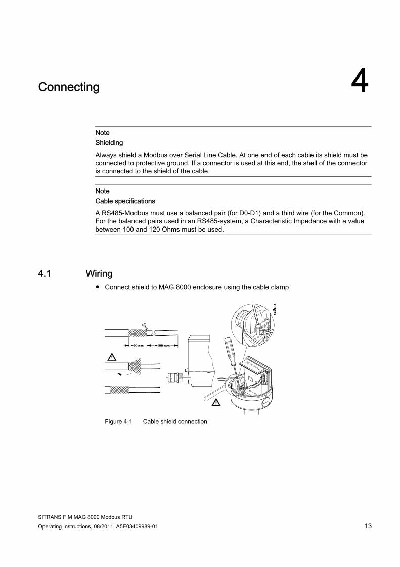
4Connecting
Note Shielding
Always shield a Modbus over Serial Line Cable. At one end of each cable its shield must be connected to protective ground. If a connector is used at this end, the shell of the connector is connected to the shield of the cable.
Note Cable specifications
A RS485-Modbus must use a balanced pair (for D0-D1) and a third wire (for the Common). For the balanced pairs used in an RS485-system, a Characteristic Impedance with a value between 100 and 120 Ohms must be used.
4.1 Wiring ● Connect shield to MAG 8000 enclosure using the cable clamp
Figure 4-1 Cable shield connection

Connecting 4.1 Wiring
SITRANS F M MAG 8000 Modbus RTU 14 Operating Instructions, 08/2011, A5E03409989-01
RS232 connection diagram
① Common ② Connect shield to enclosure ③ Shield connected to protective ground
① Common
RS485 connection diagram
① Common ② Connect shield to enclosure ③ Shield connected to protective ground
Connecting 4.2 Closing the device
SITRANS F M MAG 8000 Modbus RTU Operating Instructions, 08/2011, A5E03409989-01 15
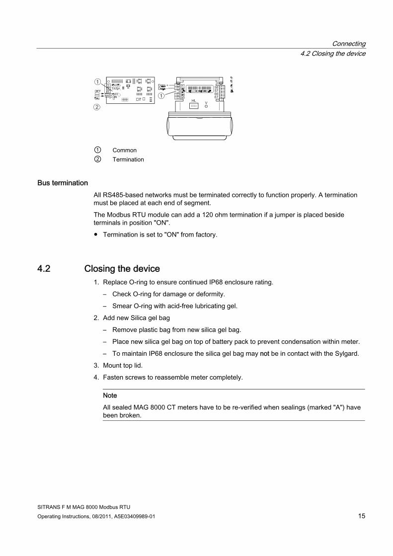
① Common ② Termination
Bus termination All RS485-based networks must be terminated correctly to function properly. A termination must be placed at each end of segment.
The Modbus RTU module can add a 120 ohm termination if a jumper is placed beside terminals in position "ON".
● Termination is set to "ON" from factory.
4.2 Closing the device 1. Replace O-ring to ensure continued IP68 enclosure rating.
– Check O-ring for damage or deformity.
– Smear O-ring with acid-free lubricating gel.
2. Add new Silica gel bag
– Remove plastic bag from new silica gel bag.
– Place new silica gel bag on top of battery pack to prevent condensation within meter.
– To maintain IP68 enclosure the silica gel bag may not be in contact with the Sylgard.
3. Mount top lid.
4. Fasten screws to reassemble meter completely.
Note
All sealed MAG 8000 CT meters have to be re-verified when sealings (marked "A") have been broken.

Connecting 4.2 Closing the device
SITRANS F M MAG 8000 Modbus RTU 16 Operating Instructions, 08/2011, A5E03409989-01
NOTICE Loss of degree of protection
Damage to device if the enclosure is open or not properly closed. The degree of protection specified on the nameplate or in "Technical data" is no longer guaranteed. • Make sure that the device is securely closed.
See also Technical data (Page 37)

SITRANS F M MAG 8000 Modbus RTU Operating Instructions, 08/2011, A5E03409989-01 17
System integration 55.1 System integration instructions
This chapter provides information on how to integrate the flowmeter in a Modbus RTU automation and control system.
The chapter shows the necessary steps in order to put the system into operation. After finishing the steps, the system is ready to go into normal operation in the Modbus RTU automation control system.
Note Storage location
All Modbus settings of the transmitter are stored in the transmitter in a non-volatile memory.
Device name and address The transmitter is shipped with a default device name and serial number.
All devices are shipped with a temporary address that allows the host to automatically commission the transmitter. The network address is the current device address used by the fieldbus.
Note
It is recommended NOT to use the default address in a multi-slave network. It is of great importance to ensure that no devices have the same address. Otherwise an abnormal behaviour of the whole serial bus can occur, the master being unable to communicate with all present slaves on the bus.
5.2 Function check Before proceeding further, make sure that installation and connection have been performed successfully.
● See chapter "Hardware installation (Page 11)" for installation verification.
● See chapter "Connecting (Page 13)" for connection verification.
When the function check has been successfully carried out, the device can be switched on.

System integration 5.3 Communication parameter settings
SITRANS F M MAG 8000 Modbus RTU 18 Operating Instructions, 08/2011, A5E03409989-01
5.3 Communication parameter settings
Effect of changing baudrate or framing Changing baudrate or framing has effect on the communication as follows:
When changed from the Modbus master, the new settings only have effect after a reset (PowerUp) of the device– or after writing to the "ResetCommunication" coil.
Table 5- 1 Communication parameters
Item Value Description Device Communication Address 1-247 Device address [Factory setting: 1] Baud rate 1200, 2400, 4800, 9600, 19200, 38400 Communication speed
[Factory setting: 19200] Parity • Even, 1 stop bit
• Odd, 1 stop bit • None, 2 stop bit • None, 1 stop bit
Communication parameters [Factory setting: Even, 1 stopbit ]
Interframe Space 35-255 chars The minimum interframe space between two Modbus RTU messages in sequence (specified as 3.5 characters) is configurable. Range: 3.5 – 25 character times. Specified in bytes times ten. [Factory setting: 35 ]
Response Delay 0-255 msec. The minimum time from when a slave receives a request and until it returns a response. This makes it possible to send data to slow masters. [Factory setting: 5 ]
5.4 Parameter access
Write protection Writable parameters in the MAG 8000 are protected by a software password. Some parameters with influence on the accuracy or identity of the flowmeter are furthermore protected by a hardware lock.
For information on how to unlock parameters protected by a hardware lock, refer to the MAG 8000 Operating Instructions.

System integration 5.5 Commissioning with PDM
SITRANS F M MAG 8000 Modbus RTU Operating Instructions, 08/2011, A5E03409989-01 19
Parameter access When attempting to write a parameter without a password, MAG 8000 will return "Illegal data address" exception code.
To successfully change a parameter, use the following routine:
1. Write the password to parameter "Meter Access Code" at address 2007. Default password is "1000"
2. Change the parameter.
When the correct password has been entered, the flowmeter remains "unlocked" for 10 minutes after last communication.
If a parameter is write-protected by a hardware lock, the MAG 8000 will return "Illegal data address".
5.5 Commissioning with PDM
5.5.1 General instructions SIMATIC PDM (Process Device Manager) is a software package for configuring, parameterizing, commissioning and maintaining devices (e.g. transducers) and for configuring networks and PCs.
Among other features, SIMATIC PDM contains a simple process monitoring of process values, interrupts and status/diagnosis signals of device.
Note
For instructions on installation and operation of SIMATIC PDM, please refer to the SIMATIC PDM Getting Started
NOTICE Infrared communication
Activated infrared communication blocks all communication with a wired Modbus master. • Ensure that no infrared communication is activated before communicating with the wired
Modbus master.
5.5.2 Commissioning steps In the following it is described how to commission the device with SIMATIC PDM.
The steps are divided into the following sections:

System integration 5.5 Commissioning with PDM
SITRANS F M MAG 8000 Modbus RTU 20 Operating Instructions, 08/2011, A5E03409989-01
1. Install the EDD files (Page 20)
2. Add the device to the communication network (Page 21)
3. Configure the device (Page 22). Describes the setup of the basic parameters of the flowmeter.
4. Operation (Page 24). Describes how to view all available process values.
5.5.3 Installing EDD files
Installing EDD files Procedure for installing PDM device driver consists of the following steps:
● Download update from the Internet on MAG 8000 Downloads (http://support.automation.siemens.com/WW/view/en/19701862/133100) , or copy it from supplied CD into envisaged folder and unzip file. It is recommended to check that the EDD is the version valid for the device.
● Open "Manage Device Catalog" from Start > SIMATIC > SIMATIC PDM.
● Navigate to PDM device driver, select device and click "OK" and driver is installed on PC.

System integration 5.5 Commissioning with PDM
SITRANS F M MAG 8000 Modbus RTU Operating Instructions, 08/2011, A5E03409989-01 21
5.5.4 Adding device to network Before setting the parameters, it is necessary to configure the MAG 8000 project in PDM.
1. Add the device to SIMATIC Modbus network:
– Select "File"->"New" Type in a project name, e.g. MAG 8000
– Right click on "Net" and select "Insert New Object"->"Modbus Net". Your PC is now added to the Modbus Net, e.g. NOG0482D
– Right click on "Modbus Net" and select "Insert New Object"->"Modbus Device".
– Click on "Assign" and assign the Modbus device to MAG8000 Advanced or Basic (Sensors->Flow->Electromagnetic->SIEMENS AG->MAG8000) and click "ok".
Figure 5-1 Assigning Modbus device to network
– Rename the device according to the application requirements (max. 32 characters).
2. Set up the communication parameters for SIMATIC Modbus network.
– Select "Net"->"Modbus net", right click on "Modbus net" and select "Object Properties"
– Select "Connection" and set "data transmission rate" to "19200 Baud" and "Vertical parity position" to "0 - even"

System integration 5.5 Commissioning with PDM
SITRANS F M MAG 8000 Modbus RTU 22 Operating Instructions, 08/2011, A5E03409989-01
Figure 5-2 MODBUS net Object properties
5.5.5 Configuring the device
Read all parameters Before any parameterization is done it is necessary to read all parameters from the device into the offline table of SIMATIC PDM. The offline table merely contains default data.
1. Open the PDM device driver.
2. Select "Device->Upload to PC/PG .." Select "Execute even if the device TAG does not match the project data TAG." and click "OK" to read all parameters to the offline table. After closing the dialog all loaded parameters should show "Loaded" in the status of the PDM table.
System integration 5.5 Commissioning with PDM
SITRANS F M MAG 8000 Modbus RTU Operating Instructions, 08/2011, A5E03409989-01 23
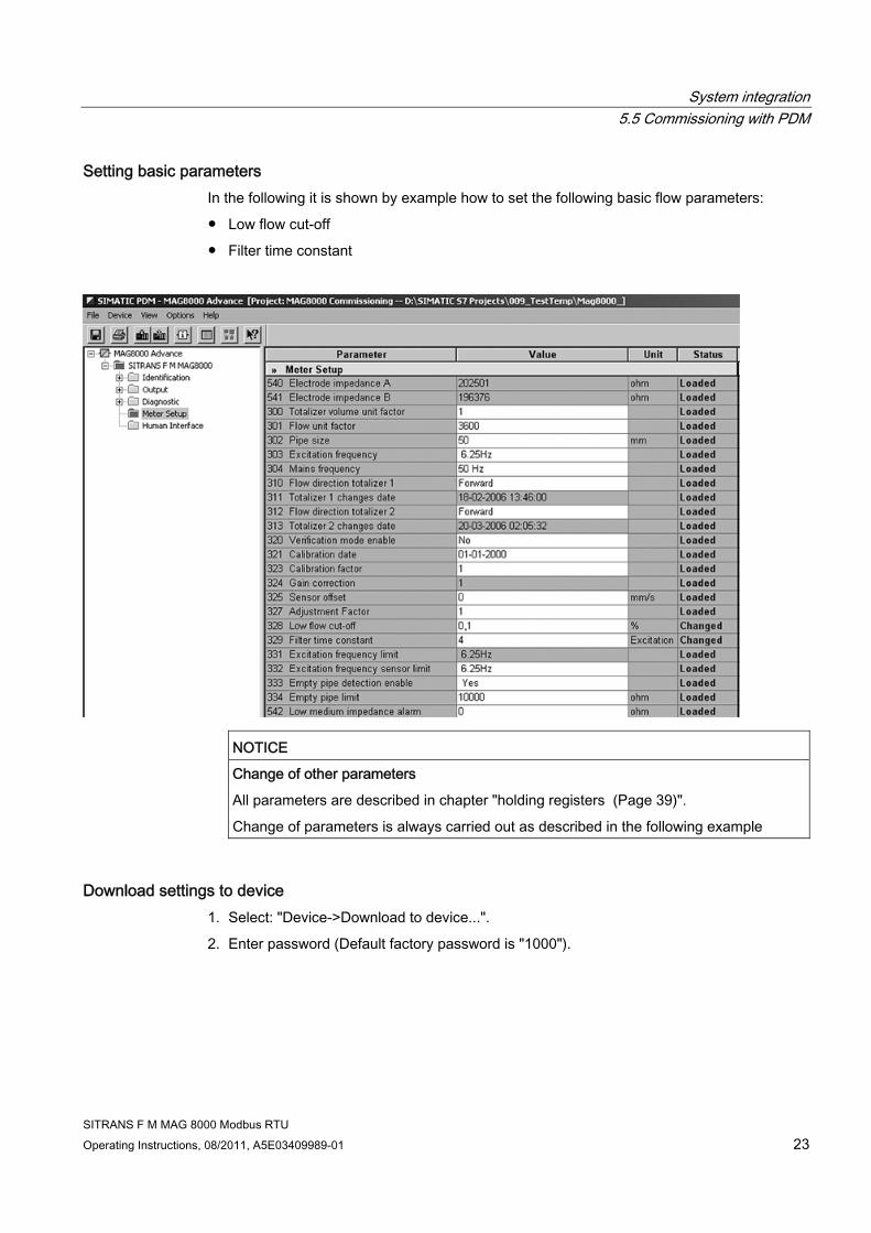
Setting basic parameters In the following it is shown by example how to set the following basic flow parameters:
● Low flow cut-off
● Filter time constant
NOTICE
Change of other parameters
All parameters are described in chapter "holding registers (Page 39)".
Change of parameters is always carried out as described in the following example
Download settings to device 1. Select: "Device->Download to device...".
2. Enter password (Default factory password is "1000").
System integration 5.5 Commissioning with PDM
SITRANS F M MAG 8000 Modbus RTU 24 Operating Instructions, 08/2011, A5E03409989-01
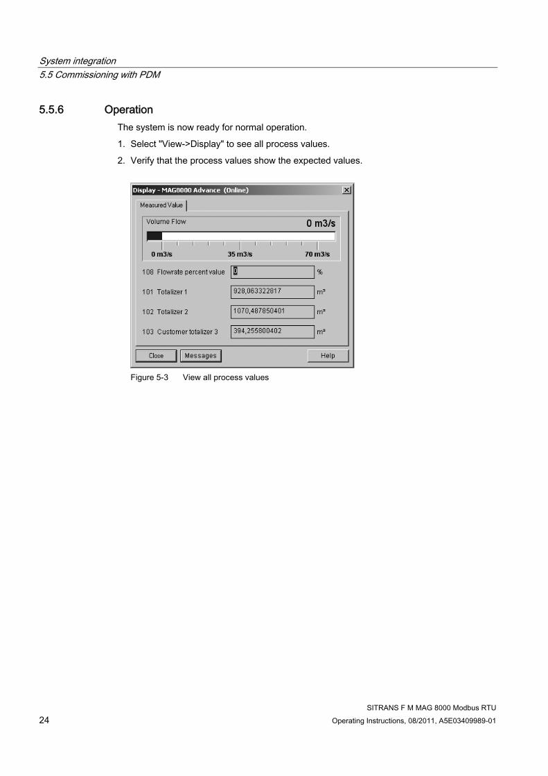
5.5.6 Operation The system is now ready for normal operation.
1. Select "View->Display" to see all process values.
2. Verify that the process values show the expected values.
Figure 5-3 View all process values
SITRANS F M MAG 8000 Modbus RTU Operating Instructions, 08/2011, A5E03409989-01 25
Function codes 66.1 Modbus Commands
Modbus addressing model The module allows R/W access to the following standard Modbus data register blocks:
● Coils (ref. 0x address range)
● Holding Registers (ref. 4x address range)
I.e. the module will not support the other standard data register blocks:
● "Discrete Input" (ref. 1x address range)
● "Input Registers"(ref. 3x address range)
Commands Broadcast communication from master to slave(s) through device address 0 is supported. No response from the slave is generated in that case. Broadcast communication is not secured by the normal check mechanisms and shall be limited to very few uses.
A SITRANS F Modbus slave only recognizes (and accepts) few Modbus RTU commands/function codes.
Supported function codes are listed in the table below.
Table 6- 1 Function codes
Function code Command text Description 01 hex Read coils Reads the status of single bit(s) in a slave 03 hex Read multiple registers Reads the binary content of multiple 16-bit registers in the slave.
The maximum number of registers is 26 05 hex Write single coil Writes a single on/off bit 10 hex Write multiple registers Preset values into a sequence of 16-bit registers. The maximum
number of registers is 25 11 hex Report Slave ID The SITRANS F slave will respond to a Report Slave ID command
(Command 17) request from the master by giving information about device type, vendor, revision level etc. in a format as shown
Function codes 6.2 Read coils
SITRANS F M MAG 8000 Modbus RTU 26 Operating Instructions, 08/2011, A5E03409989-01
6.2 Read coils
Command messages The read coils functions (01 hex) allow the master to request information from the slave. The command message of a coil read is structured as shown below. Each row in the table compares to a byte in the message – top byte (Slave address) is transmitted first.
The initial slave address is 1. Address 0 (broadcast) and other values between 1 and 255 can be used.
The function code of this message is 01 hex (read coil) .
The starting coil is the first binary data to be read.
The quantity indicates how many consecutive bits are to be read. The quantity may range from 1 to 432 bits.
A CRC value is generated from a calculation using the values of the slave address, function code, and data sections of the message. When the slave receives the command message it calculates a CRC-16 value and compares it to the one in the CRC-16 field of the command message. If these two CRC-16 values are the same the slave has received the proper command message. If the two CRC-16 values are not the same the slave will not respond.
Table 6- 2 Read coil command messages
Message byte Example Slave address xx hex Function code 01 hex Starting coil Upper 00 hex Lower 00 hex Quantity Upper 00 hex Lower xx hex CRC-16 Lower xx hex Upper xx hex
Normal response If the command message has a valid slave address, function code, starting coil and quantity value, the slave will respond with a normal response message. If the command message has an invalid slave address, function code, starting coil and/or quantity, the slave will respond with an exception response message.
The normal response message contains the same slave address and function code as the command message.
The Bit count is the number of status bits returned in the response message. The number equals the quantity in the command message.
The data section of the response message contains a number of bits representing the status of the coils(s) that has been read from the device. The LSB of the coil status byte indicates the status of the coil.

Function codes 6.2 Read coils
SITRANS F M MAG 8000 Modbus RTU Operating Instructions, 08/2011, A5E03409989-01 27
Table 6- 3 Read coil normal response messages
Message byte Example Slave address xx hex Function code 01 hex Bit count xx hex Coil status byte(s) xx hex xx hex Next coil status byte(s) xx hex xx hex Last coil status byte(s) xx hex xx hex CRC-16 Lower xx hex Upper xx hex
Exception response The exception response message contains the same slave address as the command message.
The function code of the exception message is actually a value of 80 hex plus the original function code of 01 hex.
The exception code indicates where the error occurred in the command message. A complete listing of exception codes is shown in a later chapter.
Table 6- 4 Read coil exception response messages
Message byte Example Slave address xx hex Function code 81 hex Exception code 02 hex CRC-16 Lower xx hex Upper xx hex
Example Read Coil Customer Totalizer (0:00018):
● Query: 1,1,0,18,0,1,93,207 (Hex 01,01,00,12,00,01,5D,CF)
● Response: 1,1,1,0,81,136 (Hex 01,01,01,00,51,88)

Function codes 6.3 Read multiple registers
SITRANS F M MAG 8000 Modbus RTU 28 Operating Instructions, 08/2011, A5E03409989-01
6.3 Read multiple registers
Command messages The multiple register read functions (03 hex) allows the master to request information from the slave. The command message of a multiple register read is structured as shown below. Each row in the table compares to byte in the message – top byte (Slave address) is transmitted first.
The initial slave address is 1. Address 0 (broadcast) and other values between 1 and 255 can be used.
The function code of this message is 03 hex (read multiple registers)
The starting register is the first register to be read.
The quantity indicates how many consecutive 16-bit registers are to be read. The quantity may range from 1 to 26 registers. If the quantity is greater than 26 an error code of 03 hex is returned in the exception response message.
A CRC value is generated from a calculation using the values of the slave address, function code, and data sections of the message. When the slave receives the command message it calculates a CRC-16 value and compares it to the one in the CRC-16 field of the command message. If these two CRC-16 values are the same the slave has received the proper command message. If the two CRC-16 values are not the same the slave will not respond.
If the command message has a valid slave address, function code, starting register and quantity value, the slave will respond with a normal response message. If the command message has an invalid function code, starting register and/or quantity, the slave will respond with an exception response message.
Table 6- 5 Read multiple registers command messages
Message byte Example Slave address xx hex Function code 03 hex Starting register Upper 00 hex Lower 20 hex Quantity Upper 00 hex Lower 04 hex CRC-16 Lower xx hex Upper xx hex
Normal response The normal response message contains the same slave address and function code as the command message.
The Byte count is the number of data bytes returned in the response message. The number is actually the quantity (in the command message) times 2, since there are two bytes of data in each register.
Function codes 6.3 Read multiple registers
SITRANS F M MAG 8000 Modbus RTU Operating Instructions, 08/2011, A5E03409989-01 29
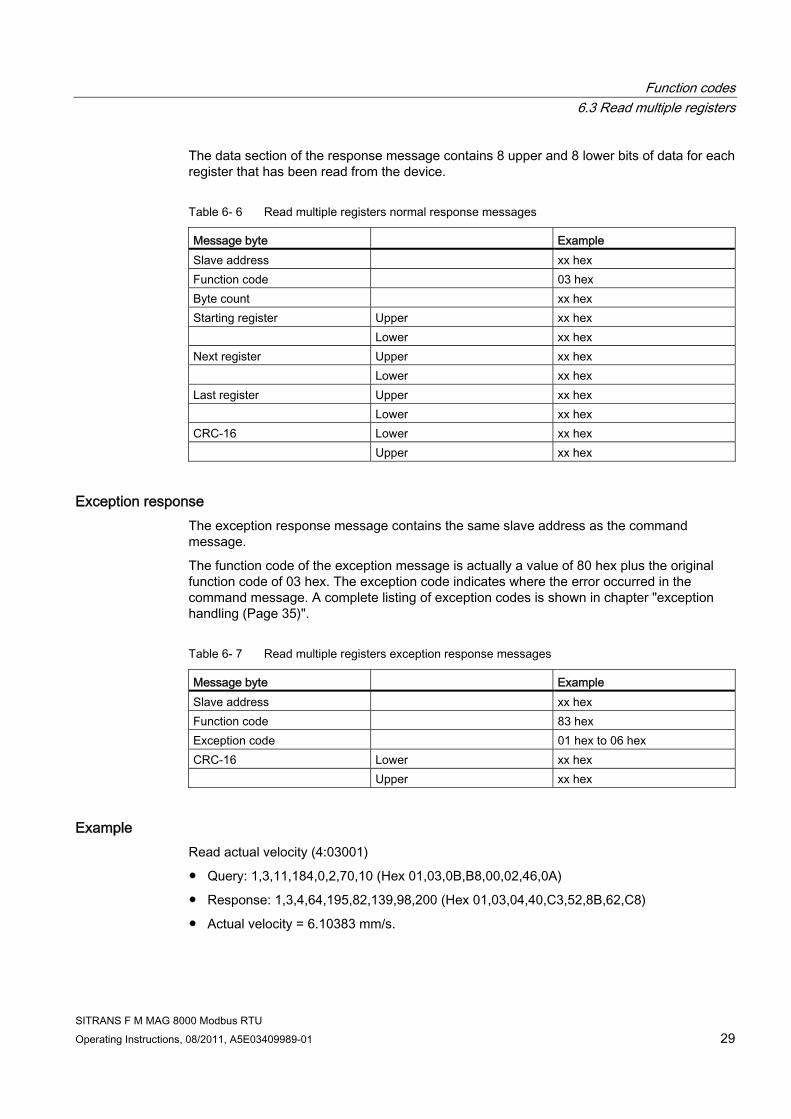
The data section of the response message contains 8 upper and 8 lower bits of data for each register that has been read from the device.
Table 6- 6 Read multiple registers normal response messages
Message byte Example Slave address xx hex Function code 03 hex Byte count xx hex Starting register Upper xx hex Lower xx hex Next register Upper xx hex Lower xx hex Last register Upper xx hex Lower xx hex CRC-16 Lower xx hex Upper xx hex
Exception response The exception response message contains the same slave address as the command message.
The function code of the exception message is actually a value of 80 hex plus the original function code of 03 hex. The exception code indicates where the error occurred in the command message. A complete listing of exception codes is shown in chapter "exception handling (Page 35)".
Table 6- 7 Read multiple registers exception response messages
Message byte Example Slave address xx hex Function code 83 hex Exception code 01 hex to 06 hex CRC-16 Lower xx hex Upper xx hex
Example Read actual velocity (4:03001)
● Query: 1,3,11,184,0,2,70,10 (Hex 01,03,0B,B8,00,02,46,0A)
● Response: 1,3,4,64,195,82,139,98,200 (Hex 01,03,04,40,C3,52,8B,62,C8)
● Actual velocity = 6.10383 mm/s.
Function codes 6.4 Write single coil
SITRANS F M MAG 8000 Modbus RTU 30 Operating Instructions, 08/2011, A5E03409989-01
6.4 Write single coil
Command messages The write coil functions (05 hex) allow the master to control single bits in the slave. The command message of a coil write is structured as shown below.
The initial slave address is 1. Address 0 (broadcast) and other values between 1 and 255 can be used.
The function code of this message is 05 hex (write coil).
The coil address is the coil to be written to.
The requested coil status is specified by a constant in the query data field. A value of FF hex , 00 hex (upper, lower) requests the coil/bit to be set. A value of 00 hex , 00 hex requests it to be reset. All other values are illegal and will not affect the coil.
CRC check and exception handling is performed as described for command ‘Read multiple registers’.
Table 6- 8 Write coil command messages
Message byte Example Slave address xx hex Function code 05 hex Coil address Upper xx hex Lower xx hex New coil value Upper FF hex or 00 hex Lower 00 hex CRC-16 Lower xx hex Upper xx hex
Normal response The normal response message contains the same slave address and function code as the command message.
The coil address is the coil that was written to.
The new coil value is the value written to the coil.
Table 6- 9 Write coil normal response messages
Message byte Example Slave address xx hex Function code 05 hex Coil address Upper xx hex Lower xx hex New coil value Upper FF hex or 00 hex
Function codes 6.5 Write multiple registers
SITRANS F M MAG 8000 Modbus RTU Operating Instructions, 08/2011, A5E03409989-01 31
Message byte Example Lower 00 hex CRC-16 Lower xx hex Upper xx hex
Exception response The exception response message contains the same slave address as the command message.
The function code of the exception message is actually a value of 80 hex plus the original function code of 05 hex. The exception code indicates where the error occurred in the command message. A complete listing of exception codes is shown in chapter "Exception handling (Page 35)".
Table 6- 10 Write coil exception response messages
Message byte Example Slave address xx hex Function code 85 hex Exception code 01 hex to 06 hex CRC-16 Lower xx hex Upper xx hex
Examples Coil 0 (Restart Modbus communication)
To activate a new baudrate and parity/framing the coil 0 (restart Modbus communication) must be sent. Otherwise a power down/up initiate a new baudrate and parity/framing:
● Query: 1,5,0,0,255,0,140,58 (Hex 01,05,00,00,FF,00,8C,3A) (Set coil 0 to 0xFF00)
● Receive: 1,5,0,0,255,0,140,58 (Hex 01,05,00,00,FF,00,8C,3A) (Restart Modbus communication)
6.5 Write multiple registers
Command messages The multiple register write functions (10 hex) allow the master to write data to the slaves registers. The command message of a multiple register write is structured as shown below.
The initial slave address is 1. Address 0 (broadcast) and other values between 1 and 255 can be used.
The function code of this message is 10 hex (write multiple registers).
The starting register is the first register to be written to.
Function codes 6.5 Write multiple registers
SITRANS F M MAG 8000 Modbus RTU 32 Operating Instructions, 08/2011, A5E03409989-01
The quantity indicates how many consecutive 16-bit registers are to be written to. The quantity may range from 1 to 25 registers. If the quantity is greater than 25, an error code of 03 hex is returned in the exception response message.
The Byte count is the number of bytes of data to be written to the device. The number of bytes is actually the quantity times 2, since there are two bytes of data in each register.
The data section of the command message contains 8 upper and 8 lower bits of data for each register that is being written to.
CRC check and exception handling is performed as described for command ‘Read multiple registers’.
Table 6- 11 Write multiple coil command messages
Message byte Example Slave address xx hex Function code 10 hex Starting register Upper 00 hex Lower 20 hex Quantity Upper 00 hex Lower 04 hex Byte count xx hex Starting register value Upper xx hex Lower xx hex Next register value Upper xx hex Lower xx hex Last register value Upper xx hex Lower xx hex CRC-16 Lower xx hex Upper xx hex
Normal response The normal response message contains the same slave address and function code as the command message.
The starting register is the first register that was written to.
The quantity value indicates how many consecutive registers were written to.
Table 6- 12 Write multiple coil normal response messages
Message byte Example Slave address xx hex Function code 10 hex Starting register Upper xx hex Lower xx hex Quantity Upper xx hex

Function codes 6.5 Write multiple registers
SITRANS F M MAG 8000 Modbus RTU Operating Instructions, 08/2011, A5E03409989-01 33
Message byte Example Lower xx hex CRC-16 Lower xx hex Upper xx hex
Exception responses The exception response message contains the same slave address as the command message.
The function code of the exception message is actually a value of 80 hex plus the original function code of 10 hex.
The exception code indicates where the error occurred in the command message. A complete listing of exception codes is shown in chapter "Exception handling (Page 35)".
Table 6- 13 Write multiple coil exception response messages
Message byte Example Slave address xx hex Function code 90 hex Exception code 01 hex to 06 hex CRC-16 Lower xx hex Upper xx hex
Example Set baud rate to 38400 baud
● Query: 1,16,2,17,0,1,2,0,5,70,210 (38400 = value 5) (Hex 01,10,02,11,00,01,02,00,05,46,D2)
● Receive: 1,16,2,17,0,1,80,116 (Hex 01,10,02,11,00,01,50,74)
To activate a new baudrate and parity/framing the coil 0 (Restart Modbus communication) must be sent.
Otherwise a power down/up initiate a new baudrate and parity/framing:
● Query: 1,5,0,0,255,0,140,58 (Hex 01,05,00,00,FF,00,8C,3A) (Set coil 0 to 0xFF00)
● Receive: 1,5,0,0,255,0,140,58 (Hex 01,05,00,00,FF,00,8C,3A) (Restart Modbus communication)

Function codes 6.6 Report slave ID command
SITRANS F M MAG 8000 Modbus RTU 34 Operating Instructions, 08/2011, A5E03409989-01
6.6 Report slave ID command All MAG 8000 will respond to a Report Slave ID command (Command 17) request from the master by giving information about device type, vendor, revision level etc. in a format as shown:
Table 6- 14 Report slave ID command messages
Message byte Example Slave address xxhex Function code 11hex
Lower xxhex CRC-16 Upper xxhex
Table 6- 15 Report slave ID messages
Message byte Description Length Slave address 1 byte Function code 1 byte Byte count 1 byte Slave ID 1 byte Run Indicator 0=Off; FF=Running 1 byte Product code 0x1B = MAG8000 1 byte Software code no
"087C4054" for MAG8000 Null terminator included
9 bytes
Capability bits Bits describing the capabilities of this module. 1.2, 2.4, 4.8, 9.6, 19.2, 38.4 kB/s
3 bytes
Manufacturer name "Siemens" (Read from EEPROM) Null terminator included
12 bytes
Product name "MAG 8000" Null terminator included
12 bytes
Product major revision 1 byte Product minor revision 1 byte Comm option name Not used in MAG 8000 11 bytes Comm option code Not used in MAG 8000 1 byte Comm option Major revision Not used in MAG 8000 1 byte CRC-16 2 bytes

Function codes 6.7 Exception handling
SITRANS F M MAG 8000 Modbus RTU Operating Instructions, 08/2011, A5E03409989-01 35
6.7 Exception handling There is a defined set of exception codes to be returned by slaves in the event of problems. All exceptions are signalled in the response from the slave by adding 80 hex to the function code of the request and following this byte by an exception code.
Table 6- 16 Exception codes
Exception code (dec)
Exception text Description
01 Illegal function The function code received in the query is not an allowable action for the slave
02 Illegal data address The data address received in the query is not an allowable address for the slave.
03 Illegal data value A value contained in the query data field is not an allowable value for the addressed location. This may indicate a fault in the structure of the remainder of a complex request, such that the implied length is incorrect.
04 Slave device failure The request is by some other reason not acceptable. It may e.g. indicate that the data value to write is evaluated to be beyond limits.
06 BUSY-acknowledge The slave is processing a long-duration command. The master should retransmit the message later when the slave is free.
If an exception code 04 is received, further requests have to be done to narrow down the exact problem.
If any doubts about the address that failed, "Last Coil/HoldReg ErrorAddr" can be read. This will return the faulty address.
Table 6- 17 Last Coil/HoldReg ErrorAddr
MODBUS register
MODBUS address
No. of bytes
Data type Description Read/ write
4:00681 680 2 Word Last Coil ErrorAddr (MODBUS cmd: 1 or 5) R 4:00682 681 2 Word Last Coil ErrorNo (127 = No error) R 4:00683 682 2 Word Last HoldReg ErrorAddr (MODBUS cmd: 3 or 16) R 4:00684 683 2 Word Last HoldReg ErrorNo (127 = No error) R
Reading "Last Coil/HoldReg ErrorNo" will return a detailed error reason. A list of error numbers can be seen below.
Table 6- 18 Error numbers
Error Number (Dec)
Error Number (Hex)
Error name Reason
3 3 Write access denied
This parameter is in a state where it is not writable
4 4 Max. limit The value was greater than the allowed maximum value

Function codes 6.7 Exception handling
SITRANS F M MAG 8000 Modbus RTU 36 Operating Instructions, 08/2011, A5E03409989-01
Error Number (Dec)
Error Number (Hex)
Error name Reason
5 5 Min. limit The value was less than the allowed minimum value
127 7F No error No problem
SITRANS F M MAG 8000 Modbus RTU Operating Instructions, 08/2011, A5E03409989-01 37
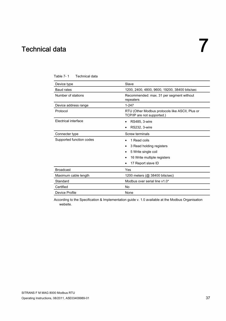
Technical data 7
Table 7- 1 Technical data
Device type Slave Baud rates 1200, 2400, 4800, 9600, 19200, 38400 bits/sec Number of stations Recommended: max. 31 per segment without
repeaters Device address range 1-247 Protocol RTU (Other Modbus protocols like ASCII, Plus or
TCP/IP are not supported.) Electrical interface • RS485, 3-wire
• RS232, 3-wire
Connecter type Screw terminals Supported function codes • 1 Read coils
• 3 Read holding registers • 5 Write single coil • 16 Write multiple registers • 17 Report slave ID
Broadcast Yes Maximum cable length 1200 meters (@ 38400 bits/sec) Standard Modbus over serial line v1.0* Certified No Device Profile None
According to the Specification & Implementation guide v. 1.0 available at the Modbus Organisation website.

Technical data
SITRANS F M MAG 8000 Modbus RTU 38 Operating Instructions, 08/2011, A5E03409989-01
SITRANS F M MAG 8000 Modbus RTU Operating Instructions, 08/2011, A5E03409989-01 39
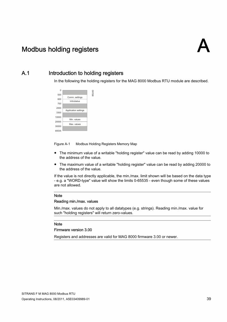
Modbus holding registers AA.1 Introduction to holding registers
In the following the holding registers for the MAG 8000 Modbus RTU module are described.
Figure A-1 Modbus Holding Registers Memory Map
● The minimum value of a writable "holding register" value can be read by adding 10000 to the address of the value.
● The maximum value of a writable "holding register" value can be read by adding 20000 to the address of the value.
If the value is not directly applicable, the min./max. limit shown will be based on the data type - e.g. a "WORD-type" value will show the limits 0-65535 - even though some of these values are not allowed.
Note Reading min./max. values
Min./max. values do not apply to all datatypes (e.g. strings). Reading min./max. value for such "holding registers" will return zero-values.
Note Firmware version 3.00
Registers and addresses are valid for MAG 8000 firmware 3.00 or newer.
Modbus holding registers A.2 MODBUS application settings
SITRANS F M MAG 8000 Modbus RTU 40 Operating Instructions, 08/2011, A5E03409989-01
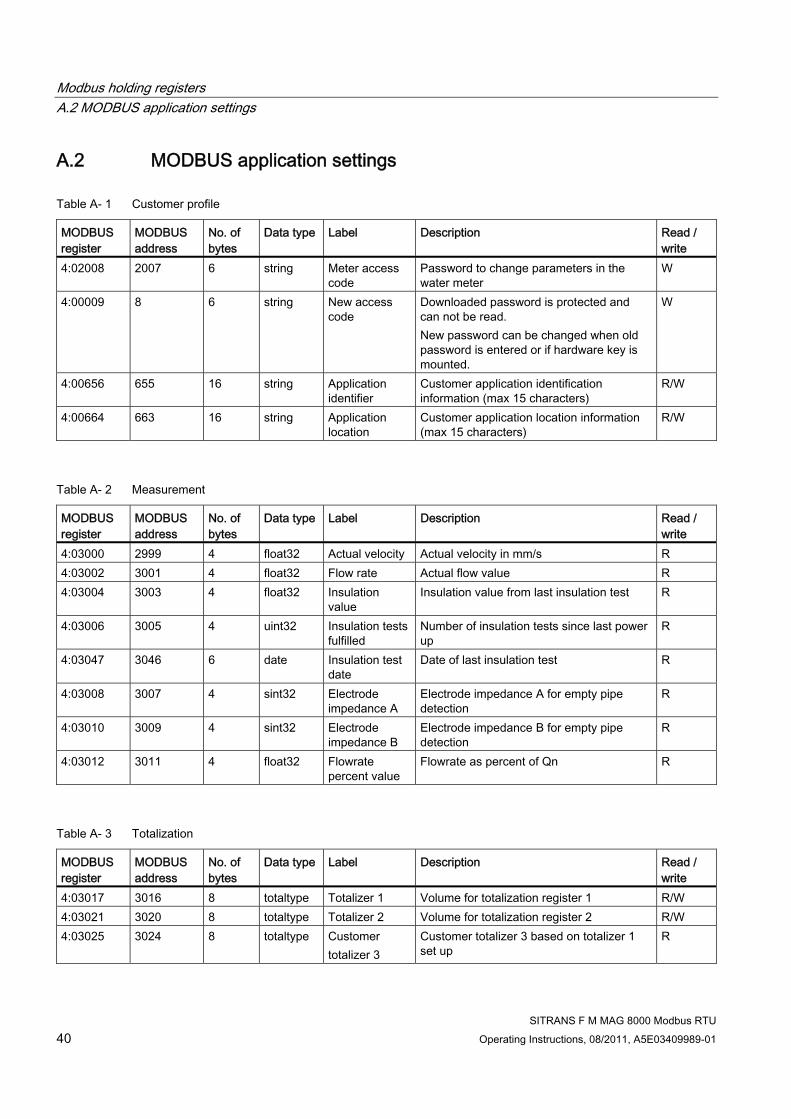
A.2 MODBUS application settings
Table A- 1 Customer profile
MODBUS register
MODBUS address
No. of bytes
Data type Label Description Read / write
4:02008 2007 6 string Meter access code
Password to change parameters in the water meter
W
4:00009 8 6 string New access code
Downloaded password is protected and can not be read. New password can be changed when old password is entered or if hardware key is mounted.
W
4:00656 655 16 string Application identifier
Customer application identification information (max 15 characters)
R/W
4:00664 663 16 string Application location
Customer application location information (max 15 characters)
R/W
Table A- 2 Measurement
MODBUS register
MODBUS address
No. of bytes
Data type Label Description Read / write
4:03000 2999 4 float32 Actual velocity Actual velocity in mm/s R 4:03002 3001 4 float32 Flow rate Actual flow value R 4:03004 3003 4 float32 Insulation
value Insulation value from last insulation test R
4:03006 3005 4 uint32 Insulation tests fulfilled
Number of insulation tests since last power up
R
4:03047 3046 6 date Insulation test date
Date of last insulation test R
4:03008 3007 4 sint32 Electrode impedance A
Electrode impedance A for empty pipe detection
R
4:03010 3009 4 sint32 Electrode impedance B
Electrode impedance B for empty pipe detection
R
4:03012 3011 4 float32 Flowrate percent value
Flowrate as percent of Qn R
Table A- 3 Totalization
MODBUS register
MODBUS address
No. of bytes
Data type Label Description Read / write
4:03017 3016 8 totaltype Totalizer 1 Volume for totalization register 1 R/W 4:03021 3020 8 totaltype Totalizer 2 Volume for totalization register 2 R/W 4:03025 3024 8 totaltype Customer
totalizer 3 Customer totalizer 3 based on totalizer 1 set up
R

Modbus holding registers A.3 MODBUS driver settings
SITRANS F M MAG 8000 Modbus RTU Operating Instructions, 08/2011, A5E03409989-01 41
A.3 MODBUS driver settings
Table A- 4 MODBUS driver settings
MODBUS register
MODBUS address
No. of bytes
Data type Label Description Read / write
4:00528 527 2 uint16 Device Communication Address
Meter has default address value "1" with selectable address up to 247
R
4:00529 528 2 uint16 Baudrate Communication port speed • 0 = 1200 • 1 = 2400 • 2 = 4800 • 3 = 9600 • 4 = 19200 • 5 = 38400
R
4:00530 529 2 uint16 Parity Communication port parity • 0 = Even 1 stop • 1 = Odd 1 stop • 2 = None 2 stop • 3 = None 1 stop
R
4:00079 78 2 uint16 Device Product ID
Siemens MAG 8000 product ID 10779 R
4:00531 530 2 uint16 Interframe space
Minimum space between two messages given in tenth bytes
R
4:00372 371 2 uint16 Response delay
Minimum time from receiving a request to its response
R
0:00000 0 1 coil Reset communication driver
Warning! Check settings before reset and accept new communications settings - otherwise communication will be interrupted! • 0 =No • 1 = Yes
R

Modbus holding registers A.4 Menu control
SITRANS F M MAG 8000 Modbus RTU 42 Operating Instructions, 08/2011, A5E03409989-01
A.4 Menu control
Table A- 5 Menu control
MODBUS register
MODBUS address
No. of bytes
Data type Label Description Read / write
4:00234 233 1 uint8 Menu active 1 byte describing which menus are enabled • Bit 1: Operator menu, • Bit 2: Meter info menu, • Bit 3: Service menu, • Bit 4: Log menu, • Bit 5: Statistic menu, • Bit 6: Revenue menu, • Bit 7: Not Used • Bit 8: Not Used Example • Menu active = 15 : • Operator; Meter info and Service menu
enabled
R
4:00402 401 1 uint8 Default operator menu index
Default menu index. Automatically selected after 10 minutes of no operation of display key. • 0 =Totalizer 1 • 1 =Totalizer 2 • 2 = Actual Flow rate • 3 = Fault codes • 4 = Customer Totalizer
R
4:00406 405 1 uint8 Decimal point Decimal point for displayed totalized value • 0 = No point • 1 = One digit after point • 2 = Two digits after point • 3 = Three digits after point • 4 = Automatic point adjust
R/W
4:00222 221 1 uint8 Displayed unit
Displayed m3 unit or an arrow indication for a unit label • 0 = m3 unit not displayed • 1 = Use m3 unit
R
Modbus holding registers A.5 Sensor characteristics
SITRANS F M MAG 8000 Modbus RTU Operating Instructions, 08/2011, A5E03409989-01 43
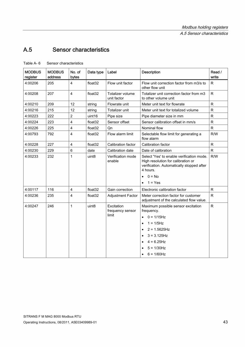
A.5 Sensor characteristics
Table A- 6 Sensor characteristics
MODBUS register
MODBUS address
No. of bytes
Data type Label Description Read / write
4:00206 205 4 float32 Flow unit factor Flow unit correction factor from m3/s to other flow unit
R
4:00208 207 4 float32 Totalizer volume unit factor
Totalizer unit correction factor from m3 to other volume unit
R
4:00210 209 12 string Flowrate unit Meter unit text for flowrate R 4:00216 215 12 string Totalizer unit Meter unit text for totalized volume R 4:00223 222 2 uint16 Pipe size Pipe diameter size in mm R 4:00224 223 4 float32 Sensor offset Sensor calibration offset in mm/s R 4:00226 225 4 float32 Qn Nominal flow R 4:00793 792 4 float32 Flow alarm limit Selectable flow limit for generating a
flow alarm R/W
4:00228 227 4 float32 Calibration factor Calibration factor R 4:00230 229 6 date Calibration date Date of calibration R 4:00233 232 1 uint8 Verification mode
enable Select 'Yes' to enable verification mode. High resolution for calibration or verification. Automatically stopped after 4 hours. • 0 = No • 1 = Yes
R/W
4:00117 116 4 float32 Gain correction Electronic calibration factor R 4:00236 235 4 float32 Adjustment Factor Meter correction factor for customer
adjustment of the calculated flow value. R
4:00247 246 1 uint8 Excitation frequency sensor limit
Maximum possible sensor excitation frequency. • 0 = 1/15Hz • 1 = 1/5Hz • 2 = 1.5625Hz • 3 = 3.125Hz • 4 = 6.25Hz • 5 = 1/30Hz • 6 = 1/60Hz
R

Modbus holding registers A.5 Sensor characteristics
SITRANS F M MAG 8000 Modbus RTU 44 Operating Instructions, 08/2011, A5E03409989-01
MODBUS register
MODBUS address
No. of bytes
Data type Label Description Read / write
4:00048 47 1 uint8 Excitation frequency limit
Maximum selectable excitation frequency • 0 = 1/15Hz • 1 = 1/5Hz • 2 = 1.5625Hz • 3 = 3.125Hz • 4 = 6.25Hz • 5 = 1/30Hz • 6 = 1/60Hz
R
4:00238 237 1 uint8 Excitation frequency
Actual selected excitation frequency • 0 = 1/15Hz • 1 = 1/5Hz • 2 = 1.5625Hz • 3 = 3.125Hz • 4 = 6.25Hz • 5 = 1/30Hz • 6 = 1/60Hz
R
4:00239 238 4 float32 Low flow cut-off If the flow subceeds this percentage of Qn, then the flowvalue is set to zero.n.
R
4:00241 240 2 uint16 Filter time constant Generel filter for flow measurement. Filter constant is the number of excitations the filtering will take place over. Higher number gives a slower and more stable flow signal.
R
4:00242 241 1 uint8 Empty pipe detection enable
Select 'Yes' to enable empty pipe detection. • 0 = No • 1 = Yes
R
4:00243 242 4 sint32 Empty pipe limit Electrode impedance in ohm for active empty pipe detection
R
4:00254 253 4 sint32 Low medium impedance alarm
Electrode impedance in ohm for active low impedance alarm detection
R/W
4:00245 244 1 uint8 Insulation test enable
Select 'Yes' for enabling insulation test • 0 = No • 1 = Yes
R/W
4:00246 245 2 uint16 Insulation test interval
Number of days between insulation tests
R/W
4:00820 819 4 float32 Reverse flow alarm limit
Selectable reverse flow limit for generating a reverse flow alarm
R/W
Modbus holding registers A.6 Totalization
SITRANS F M MAG 8000 Modbus RTU Operating Instructions, 08/2011, A5E03409989-01 45
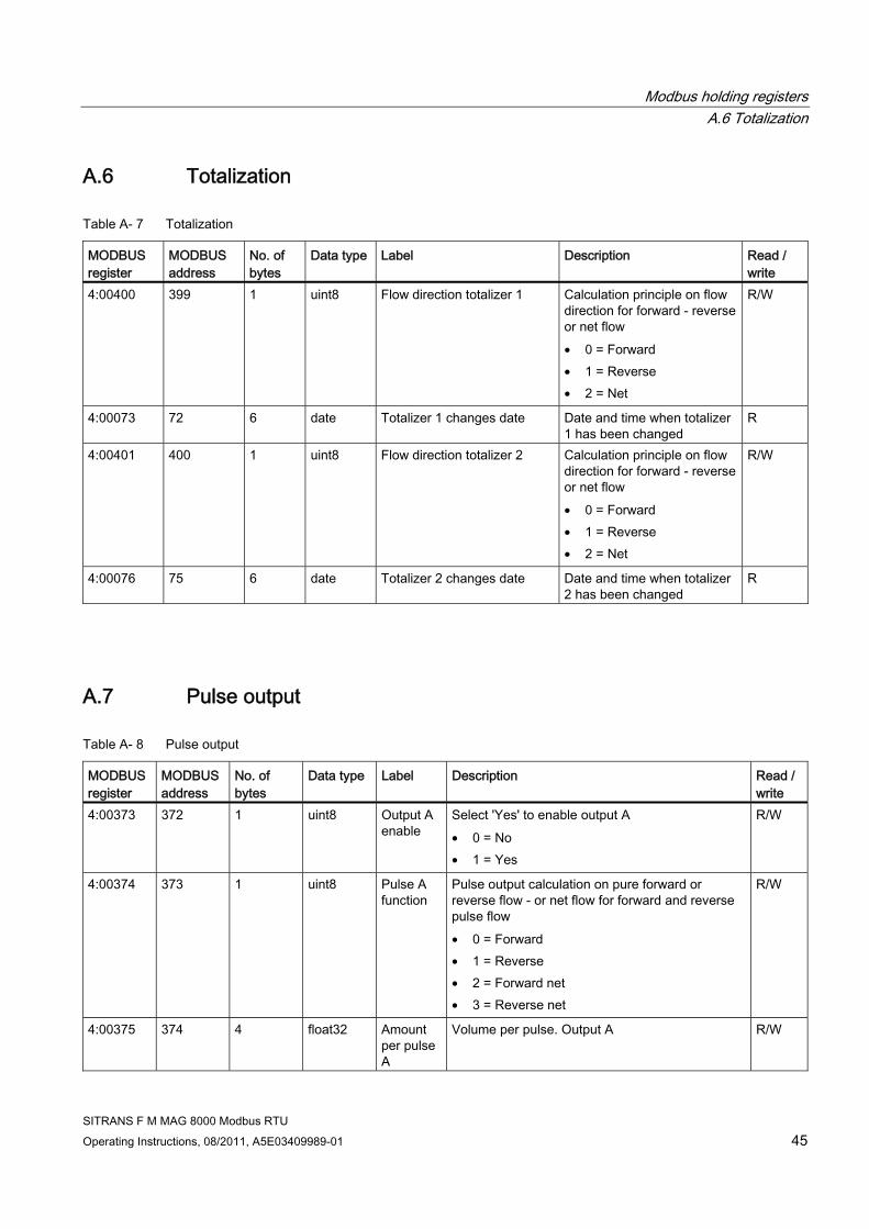
A.6 Totalization
Table A- 7 Totalization
MODBUS register
MODBUS address
No. of bytes
Data type Label Description Read / write
4:00400 399 1 uint8 Flow direction totalizer 1 Calculation principle on flow direction for forward - reverse or net flow • 0 = Forward • 1 = Reverse • 2 = Net
R/W
4:00073 72 6 date Totalizer 1 changes date Date and time when totalizer 1 has been changed
R
4:00401 400 1 uint8 Flow direction totalizer 2 Calculation principle on flow direction for forward - reverse or net flow • 0 = Forward • 1 = Reverse • 2 = Net
R/W
4:00076 75 6 date Totalizer 2 changes date Date and time when totalizer 2 has been changed
R
A.7 Pulse output
Table A- 8 Pulse output
MODBUS register
MODBUS address
No. of bytes
Data type Label Description Read / write
4:00373 372 1 uint8 Output A enable
Select 'Yes' to enable output A • 0 = No • 1 = Yes
R/W
4:00374 373 1 uint8 Pulse A function
Pulse output calculation on pure forward or reverse flow - or net flow for forward and reverse pulse flow • 0 = Forward • 1 = Reverse • 2 = Forward net • 3 = Reverse net
R/W
4:00375 374 4 float32 Amount per pulse A
Volume per pulse. Output A R/W

Modbus holding registers A.7 Pulse output
SITRANS F M MAG 8000 Modbus RTU 46 Operating Instructions, 08/2011, A5E03409989-01
MODBUS register
MODBUS address
No. of bytes
Data type Label Description Read / write
4:00377 376 1 uint8 Pulse width for pulse A
Pulse length when the pulse is active • 0 = 10 ms • 1 = 50 ms • 2 = 100 ms • 3 = 500 ms • 4 = 5 ms
R/W
4:00378 377 1 uint8 Output B enable
Select 'Yes' to enable output B • 0 = No • 1 = Yes
R/W
4:00379 378 1 uint8 Pulse B function
Configuration of output B as pulse - alarm or call up function • 0 = Pulse • 1 = Alarm • 2 = Call up
R/W
4:00380 379 1 uint8 Pulse B direction
Pulse output calculation on pure forward or reverse flow - or net flow for forward and reverse pulse flow • 0 = Forward • 1 = Reverse • 2 = Forward net • 3 = Reverse net
R/W
4:00381 380 4 float32 Amount per pulse B
Volume per pulse. Output B R/W
4:00383 382 1 uint8 Pulse width for pulse B
Pulse length when the pulse is active • 0 = 10 ms • 1 = 50 ms • 2 = 100 ms • 3 = 500 ms
R/W

Modbus holding registers A.8 Service control
SITRANS F M MAG 8000 Modbus RTU Operating Instructions, 08/2011, A5E03409989-01 47
A.8 Service control
Table A- 9 Service control
MODBUS register
MODBUS address
No. of bytes
Data type Label Description Read / write
0:00000 15 1 coil Coil current disable
Select 'Yes' to disable coil current for magnetic field • 0 = No • 1 = Yes
R
0:00000 16 1 coil Fixed flow mode enable
Select 'Yes' to enable fixed flow value • 0 = No • 1 = Yes
R
4:00361 360 4 float32 Fixed flow value
Fixed flow value for enabled fixed flow R
4:00363 362 6 date Latest service date
Latest service date (can also be used for date of installation)
R/W
4:00080 79 4 uint32 Operating hours since power up
Total operation hours since first power up R
4:00366 365 2 uint16 Numbers of power up
Total number of power up since first time power up.
R
4:03033 3032 6 date Actual date and time
Actual date and time of day-month-year and hours:minutes:seconds
R/W
A.9 Error messages
Table A- 10 Error messages
MODBUS register
MODBUS address
No. of bytes
Data type Label Description Read / write
0:00000 2 - coil Insulation alarm output enable
Select 'Yes' to enable current alarm on alarm output / call-up • 0 = No • 1 = Yes
R/W
4:00272 271 2 uint16 Insulation fault hours
Total hours fault active R
4:00273 272 1 uint8 Insulation fault counter
Total number of faults R
4:00274 273 6 date Insulation fault appears
First time the fault appeared R
4:00277 276 6 date Insulation fault disappears
Last time the fault disappeared R

Modbus holding registers A.9 Error messages
SITRANS F M MAG 8000 Modbus RTU 48 Operating Instructions, 08/2011, A5E03409989-01
MODBUS register
MODBUS address
No. of bytes
Data type Label Description Read / write
0:00000 3 - coil Coil current alarm output enable
Select 'Yes' to enable active alarm on alarm output / call-up • 0 = No • 1 = Yes
R/W
4:00281 280 1 uint8 Coil current fault counter
Total number of faults R
4:00282 281 6 date Coil current fault appears
First time the fault appeared R
0:00000 2 - coil Insulation alarm output enable
Select 'Yes' to enable current alarm on alarm output / call-up • 0 = No • 1 = Yes
R
4:00285 284 6 date Coil current fault disappears
Last time the fault disappeared R
0:00000 4 - coil Amplifier alarm output enable
Select 'Yes' to enable active alarm on alarm output / call-up • 0 = No • 1 = Yes
R/W
4:00288 287 2 uint16 Amplifier fault hours
Total hours fault active R
4:00289 288 1 uint8 Amplifier fault counter
Total number of faults R
4:00290 289 6 date Amplifier fault appears
First time the fault appeared R
4:00293 292 6 date Amplifier fault disappears
Last time the fault disappeared R
0:00000 5 - coil Parameter checksum alarm output enable
Select 'Yes' to enable active alarm on alarm output / call-up • 0 = No • 1 = Yes
R/W
4:00296 295 2 uint16 Parameter checksum fault hours
Total hours fault active R
4:00297 296 1 uint8 Parameter checksum fault counter
Total number of faults R
4:00298 297 6 date Parameter checksum fault appears
First time the fault appeared R
4:00301 300 6 date Parameter checksum fault disappears
Password to change parameters in the water meter
R

Modbus holding registers A.9 Error messages
SITRANS F M MAG 8000 Modbus RTU Operating Instructions, 08/2011, A5E03409989-01 49
MODBUS register
MODBUS address
No. of bytes
Data type Label Description Read / write
0:00000 6 - coil Low power alarm output enable
Select 'Yes' to enable active alarm on alarm output / call-up • 0 = No • 1 = Yes
R/W
4:00304 303 2 uint16 Low power fault hours
Total hours fault active R
4:00305 304 1 uint8 Low power fault counter
Total number of faults R
4:00306 305 6 date Low power fault appears
First time the fault appeared R
4:00309 308 6 date Low power fault disappears
Last time the fault disappeared R
0:00000 7 - coil Flow overflow alarm output enable
Select 'Yes' to enable active alarm on alarm output / call-up • 0 = No • 1 = Yes
R/W
4:00312 311 2 uint16 Overflow fault hours
Total hours fault active R
4:00313 312 1 uint8 Overflow fault counter
Total number of faults R
4:00314 313 6 date Overflow fault appears
First time the fault appeared R
4:00317 316 6 date Overflow fault disappears
Last time the fault disappeared R
0:00000 8 - coil Pulse A overload alarm output enable
Select 'Yes' to enable active alarm on alarm output / call-up • 0= no • 1 = Yes
R/W
4:00320 319 2 uint16 Pulse A overload fault hours
Total hours fault active R
4:00321 320 1 uint8 Pulse A overload fault counter
Total number of faults R
4:00322 321 6 date Pulse A overload fault appears
First time the fault appeared R
4:00325 324 6 date Pulse A overload fault disappears
Last time the fault disappeared R
0:00000 9 - coil Pulse B overload alarm output enable
Select 'Yes' to enable active alarm on alarm output / call-up • 0 = No • 1 = Yes
R/W
4:00328 327 2 uint16 Pulse B overload fault hours
Total hours fault active R
4:00329 328 1 uint8 Pulse B overload fault counter
Total number of faults R
Modbus holding registers A.9 Error messages
SITRANS F M MAG 8000 Modbus RTU 50 Operating Instructions, 08/2011, A5E03409989-01
MODBUS register
MODBUS address
No. of bytes
Data type Label Description Read / write
4:00330 329 6 date Pulse B overload fault appears
First time the fault appeared R
4:00333 332 6 date Pulse B overload fault disappears
Last time the fault disappeared R
0:00000 10 - coil Consumption alarm output enable
Select 'Yes' to enable active alarm on alarm output / call-up • 0 = No • 1 = Yes
R/W
4:00336 335 2 uint16 Consumption fault hours
Total hours fault active R
4:00337 336 1 uint8 Consumption fault counter
Total number of faults R
4:00338 337 6 date Consumption fault appears
First time the fault appeared R
4:00341 340 6 date Consumption fault disappears
Last time the fault disappeared R
0:00000 11 - coil Leakage alarm output enable
Select 'Yes' to enable active alarm on alarm output / call-up • 0 = No • 1 = Yes
R/W
4:00344 343 2 uint16 Leakage fault hours
Total hours fault active R
4:00345 344 1 uint8 Leakage fault counter
Total number of faults R
4:00346 345 6 date Leakage fault appears
First time the fault appeared R
4:00349 348 6 date Leakage fault disappears
Last time the fault disappeared R
0:00000 12 - coil Empty pipe alarm output enable
Select 'Yes' to enable active alarm on alarm output / call-up • 0 = No • 1 = Yes
R/W
4:00352 351 2 uint16 Empty pipe fault timer
Total hours fault active R
4:00353 352 1 uint8 Empty pipe fault counter
Total number of faults R
4:00354 353 6 date Empty pipe fault appears
First time the fault appeared R
4:00357 356 6 date Empty pipe fault disappears
Last time the fault disappeared R
0:00000 26 - coil Low impedance alarm output enable
Select 'Yes' to enable active alarm on alarm output / call-up • 0 = No • 1 = Yes
R/W

Modbus holding registers A.9 Error messages
SITRANS F M MAG 8000 Modbus RTU Operating Instructions, 08/2011, A5E03409989-01 51
MODBUS register
MODBUS address
No. of bytes
Data type Label Description Read / write
4:00795 794 2 uint16 Low impedance fault timer
Total hours fault active R
4:00796 795 1 uint8 Low impedance fault counter
Total number of faults R
4:00797 796 6 date Low impedance fault appears
First time the fault appeared R
4:00800 799 6 date Low impedance fault disappears
Last time the fault disappeared R
0:00000 27 - coil Flow alarm output enable
Select 'Yes' to enable active alarm on alarm output / call-up • 0 = No • 1 = Yes
R/W
4:00803 802 2 uint16 Flow alarm fault timer
Total hours fault active R
4:00804 803 1 uint8 Flow alarm fault counter
Total number of faults R
4:00805 804 6 date Flow alarm fault appears
First time the fault appeared R
4:00808 807 6 date Flow alarm fault disappears
Last time the fault disappeared R
0:00000 28 - coil Reverse flow alarm output enable
Select 'Yes' to enable active alarm on alarm output / call-up • 0 = No • 1 = Yes
R/W
4:00811 810 2 uint16 Reverse flow fault timer
Total hours fault active R
4:00812 811 1 uint8 Reverse flow fault counter
Total number of faults R
4:00813 812 6 date Reverse flow fault appears
First time the fault appeared R
4:00816 815 6 date Reverse flow fault disappears
Last time the fault disappeared R

Modbus holding registers A.9 Error messages
SITRANS F M MAG 8000 Modbus RTU 52 Operating Instructions, 08/2011, A5E03409989-01
MODBUS register
MODBUS address
No. of bytes
Data type Label Description Read / write
4:00360 359 2 uint16 Alarm configuration list
2 bytes describing which errors/warning should generate an alarm or call up on output B • Bit 1: Insulation error • Bit 2: Coil current error • Bit 3: Preamplifier overload • Bit 4: Database checksum error • Bit 5: Low power warning • Bit 6: Flow overload warning • Bit 7: Pulse A overload warning • Bit 8: Pulse B overload warning • Bit 9: Consumption interval warning • Bit 10/L: Leakage warning • Bit 11/E: Empty pipe warning • Bit 12/C: Low impedance warning • Bit 13/d: Flow limit warning • Bit 14/A: Reverse flow warning • Bit 15: Not used • Bit 16: Not used
R/W
4:00052 51 2 uint16 Non optimal measure time
Total hours of non optimal measurement conditions
R
4:03016 3015 2 uint16 Fault status 2 bytes describing which errors/warnings are active • Bit 1: Insulation error • Bit 2: Coil current error • Bit 3: Preamplifier overload • Bit 4: Database checksum error • Bit 5: Low power warning • Bit 6: Flow overload warning • Bit 7: Pulse A overload warning • Bit 8: Pulse B overload warning • Bit 9: Consumption interval warning • Bit 10/L: Leakage warning • Bit 11/E: Empty pipe warning • Bit 12/C: Low impedance warning • Bit 13/d: Flow limit warning • Bit 14/A: Reverse flow warning • Bit 15: Not used • Bit 16: Not used
R
Modbus holding registers A.10 Power control
SITRANS F M MAG 8000 Modbus RTU Operating Instructions, 08/2011, A5E03409989-01 53
MODBUS register
MODBUS address
No. of bytes
Data type Label Description Read / write
0:00000 14 - coil Call up acknowledge
Select 'Yes' to reset active call-up • 0 = No • 1 = Yes
R/W
4:00049 48 6 date Date of fault log reset
Date of fault log reset R
0:00000 13 - coil Reset the fault log and faults
Reset the fault log and faults • 0 = No • 1 = Reset
R/W
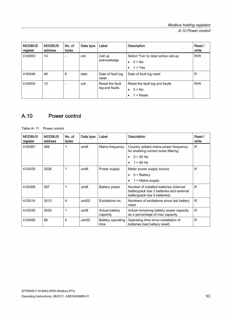
A.10 Power control
Table A- 11 Power control
MODBUS register
MODBUS address
No. of bytes
Data type Label Description Read / write
4:00367 366 1 uint8 Mains frequency Country related mains power frequency for enabling correct noise filtering • 0 = 50 Hz • 1 = 60 Hz
R
4:03029 3028 1 uint8 Power supply Meter power supply source • 0 = Battery • 1 = Mains supply
R
4:00368 367 1 uint8 Battery power Number of installed batteries (Internal batterypack has 2 batteries and external batterypack has 4 batteries)
R
4:03014 3013 4 uint32 Excitations no. Numbers of excitations since last battery reset
R
4:03030 3029 1 uint8 Actual battery capacity
Actual remaining battery power capacity as a percentage of max capacity
R
4:00089 88 4 uint32 Battery operating time
Operating time since installation of batteries (last battery reset)
R

Modbus holding registers A.10 Power control
SITRANS F M MAG 8000 Modbus RTU 54 Operating Instructions, 08/2011, A5E03409989-01
MODBUS register
MODBUS address
No. of bytes
Data type Label Description Read / write
4:03031 3030 1 uint8 Power status • 0 = Normal operation • 1 = Battery alarm. Actual battery
capacity is below battery alarm level (% of max capacity)
• 2 = Too low power (enters stand by mode)
• 3 = As value 1 and 2 together • 4 = External power gone • 5 = As value 1 and 4 together • 6 = As value 2 and 4 together • 7 = As value 1 and 2 and 4 together
R
4:00369 368 1 uint8 Battery alarm limit
Battery capacity level (%) where low power alarm will be activated.
R/W
4:03042 3041 4 float32 Transmitter temperature
Temperature inside the transmitter (°C) R
4:00091 90 6 date Battery installation date
Latest installation date of batteries R
0:00000 17 - coil Battery change enable
Select 'Yes' to set battery installation date to current date and reset remaining battery operation capacity to maximum. • 0 = No • 1 = Yes
R/W
4:00822 821 1 uint8 Communication module type
Communication module type - for calculating correct power use. • 0 = No module • 1 = RS485 • 2 = RS232 • 3 = RS232 always connected
R

Modbus holding registers A.11 Consumption statistic
SITRANS F M MAG 8000 Modbus RTU Operating Instructions, 08/2011, A5E03409989-01 55
A.11 Consumption statistic
Table A- 12 Consumption statistic
MODBUS register
MODBUS address
No. of bytes
Data type Label Description Read / write
0:00000 18 - coil Reset customer totalizer 3
Reset of customer totalizer • 0 = No • 1 = Yes
R/W
4:00098 97 6 date Customer totalizer 3 reset date
Date when customer totalizer has been reset
R
4:00407 406 4 float32 Highest flowrate Value of highest measured flow rate R 4:00409 408 6 date Date of highest
flowrate Date where highest flow rate occured R
4:00412 411 4 float32 Lowest flowrate Value of lowest measured flow rate R 4:00414 413 6 date Date of lowest
flowrate Date where lowest flow rate occured R
4:00417 416 4 float32 Highest day consumption
Value of highest measured daily consumption. Calculation based on totalizer 1
R
4:00419 418 6 date Date of highest day consumption
Date when highest measured daily consumption occured
R
4:00422 421 4 float32 Lowest day consumption
Value of lowest measured daily consumption. Calculation based on totalizer 1
R
4:00424 423 6 date Date of lowest day consumption
Date when lowest measured daily consumption occured
R
4:00164 163 4 float32 Latest week consumption
Latest week consumption (based on totalizer 1 for the last 7 days)
R
4:00162 161 4 float32 Day 1 (yesterday) of last week consumption
Latest day consumption (based on totalizer 1)
R
4:00101 100 4 float32 Day 2 of last week consumption
Latest day-1 consumption (based on totalizer 1)
R
4:00033 32 4 float32 Day 3 of last week consumption
Latest day-2 consumption (based on totalizer 1)
R
4:00035 34 4 float32 Day 4 of last week consumption
Latest day-3 consumption (based on totalizer 1)
R
4:00037 36 4 float32 Day 5 of last week consumption
Latest day-4 consumption (based on totalizer 1)
R
4:00039 38 4 float32 Day 6 of last week consumption
Latest day-5 consumption (based on totalizer 1)
R

Modbus holding registers A.12 Consumption profile
SITRANS F M MAG 8000 Modbus RTU 56 Operating Instructions, 08/2011, A5E03409989-01
MODBUS register
MODBUS address
No. of bytes
Data type Label Description Read / write
4:00041 40 4 float32 Day 7 (7 days ago) of last week consumption
Latest day-6 consumption (based on totalizer 1)
R
4:03044 3043 4 float32 Actual month consumption
Actual month consumption (based on totalizer 1 from the first in the month)
R
4:00166 165 4 float32 Latest month consumption
Latest month consumption (based on totalizer 1 from the first in the month)
R
4:00427 426 6 date Reset date of statistic inf.
Date of log reset of statistic information R
0:00000 19 - coil Reset statistic information
Reset the statistic information log • 0 = No • 1 = Yes
R/W
A.12 Consumption profile
Table A- 13 Consumption profile
MODBUS register
MODBUS address
No. of bytes
Data type Label Description Read / write
4:00430 429 1 uint8 Upper limit in CP range 1
Consumption flow range 1 - from 0 to upper limit 1 as a percent of Qn
R/W
4:00431 430 4 float32 Total time in CP range 1
Total hours of flow rate in flow range 1 R
4:00433 432 1 uint8 Upper limit in CP range 2
Consumption flow range 2 - from previous flow range to upper limit 2 as a percent of Qn
R/W
4:00434 433 4 float32 Total time in CP range 2
Total hours of flow rate in flow range 2 R
4:00436 435 1 uint8 Upper limit in CP range 3
Consumption flow range 3 - from previous flow range to upper limit 3 as a percent of Qn
R/W
4:00437 436 4 float32 Total time in CP range 3
Total hours of flow rate in flow range 3 R
4:00439 438 1 uint8 Upper limit in CP range 4
Consumption flow range 4 - from previous flow range to upper limit 4 as a percent of Qn
R/W
4:00440 439 4 float32 Total time in CP range 4
Total hours of flow rate in flow range 4 R
4:00442 441 1 uint8 Upper limit in CP range 5
Consumption flow range 5 - from previous flow range to upper limit 5 as a percent of Qn
R/W
4:00443 442 4 float32 Total time in CP range 5
Total hours of flow rate in flow range 5 R
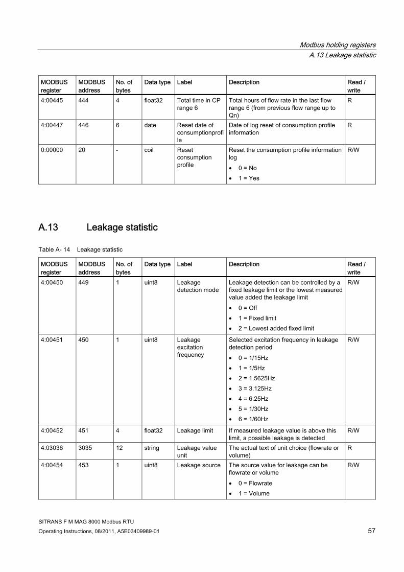
Modbus holding registers A.13 Leakage statistic
SITRANS F M MAG 8000 Modbus RTU Operating Instructions, 08/2011, A5E03409989-01 57
MODBUS register
MODBUS address
No. of bytes
Data type Label Description Read / write
4:00445 444 4 float32 Total time in CP range 6
Total hours of flow rate in the last flow range 6 (from previous flow range up to Qn)
R
4:00447 446 6 date Reset date of consumptionprofile
Date of log reset of consumption profile information
R
0:00000 20 - coil Reset consumption profile
Reset the consumption profile information log • 0 = No • 1 = Yes
R/W
A.13 Leakage statistic
Table A- 14 Leakage statistic
MODBUS register
MODBUS address
No. of bytes
Data type Label Description Read / write
4:00450 449 1 uint8 Leakage detection mode
Leakage detection can be controlled by a fixed leakage limit or the lowest measured value added the leakage limit • 0 = Off • 1 = Fixed limit • 2 = Lowest added fixed limit
R/W
4:00451 450 1 uint8 Leakage excitation frequency
Selected excitation frequency in leakage detection period • 0 = 1/15Hz • 1 = 1/5Hz • 2 = 1.5625Hz • 3 = 3.125Hz • 4 = 6.25Hz • 5 = 1/30Hz • 6 = 1/60Hz
R/W
4:00452 451 4 float32 Leakage limit If measured leakage value is above this limit, a possible leakage is detected
R/W
4:03036 3035 12 string Leakage value unit
The actual text of unit choice (flowrate or volume)
R
4:00454 453 1 uint8 Leakage source The source value for leakage can be flowrate or volume • 0 = Flowrate • 1 = Volume
R/W

Modbus holding registers A.13 Leakage statistic
SITRANS F M MAG 8000 Modbus RTU 58 Operating Instructions, 08/2011, A5E03409989-01
MODBUS register
MODBUS address
No. of bytes
Data type Label Description Read / write
4:00455 454 2 uint16 Start period for leakage detection
Time of day to start the leakage detection period
R/W
4:00456 455 1 uint8 Duration leakage detection
Leakage detection duration in 10 minutes resolution
R/W
4:00457 456 1 uint8 Periods with possible leakage
Actual days/periods where measured leakage value is above leakage limit
R
4:00458 457 1 uint8 Leakage periods before alarm
Number of days / periods before leakage fault/alarm appears
R/W
4:00459 458 4 float32 Lowest measured leakage value
Lowest measured value in leakage period R
4:00461 460 6 date Date of lowest leakage value
Date of lowest measured value R
4:00464 463 4 float32 Highest measured leakage value
Highest measured value in leakage period
R
4:00466 465 6 date Date of highest leakage value
Date of highest measured value R
4:00469 468 4 float32 Latest leakage period flowrate
Last period lowest flow value R
4:00370 369 4 float32 Latest leakage period volume
Latest leakage period totalized R
0:00000 22 - coil Reset leakage fault
Reset the leakage fault. • 0 = No • 1 =Yes
R/W
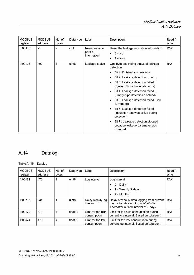
Modbus holding registers A.14 Datalog
SITRANS F M MAG 8000 Modbus RTU Operating Instructions, 08/2011, A5E03409989-01 59
MODBUS register
MODBUS address
No. of bytes
Data type Label Description Read / write
0:00000 21 - coil Reset leakage period information
Reset the leakage indication information • 0 = No • 1 = Yes
R/W
4:00403 402 1 uint8 Leakage status One byte describing status of leakage detection • Bit 1: Finished successfully • Bit 2: Leakage detection running • Bit 3: Leakage detection failed
(SystemStatus have fatal error) • Bit 4: Leakage detection failed
(Empty-pipe detection disabled) • Bit 5: Leakage detection failed (Coil
current off) • Bit 6: Leakage detection failed
(Insulation test was active during detection)
• Bit 7 : Leakage detection stopped because leakage parameter was changed.
R/W
A.14 Datalog
Table A- 15 Datalog
MODBUS register
MODBUS address
No. of bytes
Data type Label Description Read / write
4:00471 470 1 uint8 Log interval Log interval • 0 = Daily • 1 = Weekly (7 days) • 2 = Monthly
R/W
4:00235 234 1 uint8 Delay weekly log interval
Delay of weekly data logging from current day to first day logging at 00:00:00. Thereafter a fixed interval of 7 days.
R/W
4:00472 471 4 float32 Limit for too high consumption
Limit for too high consumption during current log interval. Based on totalizer 1
R/W
4:00474 473 4 float32 Limit for too low consumption
Limit for too low consumption during current log interval. Based on totalizer 1
R/W

Modbus holding registers A.14 Datalog
SITRANS F M MAG 8000 Modbus RTU 60 Operating Instructions, 08/2011, A5E03409989-01
MODBUS register
MODBUS address
No. of bytes
Data type Label Description Read / write
0:00000 23 - coil Reset consumption log fault
Reset the consumption fault. Caused by too low or too high consumption in the log interval • 0 = No • 1 = Yes
R/W
4:00476 475 6 date Date of latest log period
Date of latest stored value for log 1 R
4:00479 478 4 float32 Latest Log period totalized (1)
Latest logged value of consumption based on totalizer 1
R
4:00481 480 4 float32 Latest Log period totalized (2)
Latest logged value of consumption based on totalizer 2
R
4:00483 482 2 uint16 Latest Log period fault status
Two bytes describing fault status in log period • Bit 1: Insulation error • Bit 2: Coil current error • Bit 3: Preamplifier overload • Bit 4: Database checksum error • Bit 5: Low power warning • Bit 6: Flow overload warning • Bit 7: Pulse A overload warning • Bit 8: Pulse B overload warning • Bit 9: Consumption interval warning • Bit 10/L: Leakage warning • Bit 11/E: Empty pipe warning • Bit 12/C: Low impedance warning • Bit 13/d: Flow limit warning • Bit 14: Not used • Bit 15: Not used • Bit 16: Not used
R
4:00484 483 1 uint8 Latest Log period status information
One byte describing status information in log period • Bit 1: Totalizer 1 or 2 changed or reset • Bit 2: Tariff setting changed or reset • Bit 3: Tariff register changed or reset • Bit 4: Date - time changed • Bit 5: Alarm active in logged period
(See alarm fault log) • Bit 6: Fault log has been reset • Bit 7: HW lock broken • Bit 8: Power Up
R

Modbus holding registers A.14 Datalog
SITRANS F M MAG 8000 Modbus RTU Operating Instructions, 08/2011, A5E03409989-01 61
MODBUS register
MODBUS address
No. of bytes
Data type Label Description Read / write
4:00485 484 6 date Date of log period 2
Date where value for log 2 is stored R
4:00488 487 4 float32 Log period 2 totalized (1)
Previous logged value of consumption based on totalizer 1
R
4:00490 489 4 float32 Log period 2 totalized (2)
Previous logged value of consumption based on totalizer 2
R
4:00492 491 2 uint16 Log period 2 fault status
Two bytes describing fault status in log period • Bit 1: Insulation error • Bit 2: Coil current error • Bit 3: Preamplifier overload • Bit 4: Database checksum error • Bit 5: Low power warning • Bit 6: Flow overload warning • Bit 7: Pulse A overload warning • Bit 8: Pulse B overload warning • Bit 9: Consumption interval warning • Bit 10/L: Leakage warning • Bit 11/E: Empty pipe warning • Bit 12/C: Low impedance warning • Bit 13/d: Flow limit warning • Bit 14: Not used • Bit 15: Not used • Bit 16: Not used
R
4:00493 492 1 uint8 Log period 2 status information
One byte describing status information in log period • Bit 1: Totalizer 1 or 2 changed or reset• Bit 2: Tariff setting changed or reset • Bit 3: Tariff register changed or reset • Bit 4: Date - time changed • Bit 5: Alarm active in logged period
(See alarm fault log) • Bit 6: Fault log has been reset • Bit 7: HW lock broken • Bit 8: Power Up
R
4:00494 493 6 date Date of log period 3
Date where value for log 3 is stored R
4:00497 496 4 float32 Log period 3 totalized (1)
Log period 3 logged value of consumption based on totalizer 1
R
4:00499 498 4 float32 Log period 3 totalized (2)
Log period 3 logged value of consumption based on totalizer 2
R

Modbus holding registers A.14 Datalog
SITRANS F M MAG 8000 Modbus RTU 62 Operating Instructions, 08/2011, A5E03409989-01
MODBUS register
MODBUS address
No. of bytes
Data type Label Description Read / write
4:00501 500 2 uint16 Log period 3 fault status
See log period 2 R
4:00502 501 1 uint8 Log period 3 status information
See log period 2 R
4:00503 502 6 date Date of log period 4
Date where value for log 4 is stored R
4:00506 505 4 float32 Log period 4 totalized (1)
Log period 4 logged value of consumption based on totalizer 1
R
4:00508 507 4 float32 Log period 4 totalized (2)
Log period 4 logged value of consumption based on totalizer 2
R
4:00510 509 2 uint16 Log period 4 fault status
See log period 2 R
4:00511 510 1 uint8 Log period 4 status information
See log period 2 R
4:00532 531 6 date Date of log period 5
Date where value for log 5 is stored R
4:00535 534 4 float32 Log period 5 totalized (1)
Log period 5 logged value of consumption based on totalizer 1
R
4:00537 536 4 float32 Log period 5 totalized (2)
Log period 5 logged value of consumption based on totalizer 2
R
4:00539 538 2 uint16 Log period 5 fault status
See log period 2 R
4:00540 539 1 uint8 Log period 5 status information
See log period 2 R
4:00541 540 6 date Date of log period 6
Date where value for log 6 is stored R
4:00544 543 4 float32 Log period 6 totalized (1)
Log period 6 logged value of consumption based on totalizer 1
R
4:00546 545 4 float32 Log period 6 totalized (2)
Log period 6 logged value of consumption based on totalizer 2
R
4:00548 547 2 uint16 Log period 6 fault status
See log period 2 R
4:00549 548 1 uint8 Log period 6 status information
See log period 2 R
4:00550 549 6 date Date of log period 7
Date where value for log 7 is stored R
4:00553 552 4 float32 Log period 7 totalized (1)
Log period 7 logged value of consumption based on totalizer 1
R
4:00555 554 4 float32 Log period 7 totalized (2)
Log period 7 logged value of consumption based on totalizer 2
R
4:00557 556 2 uint16 Log period 7 fault status
See log period 2 R

Modbus holding registers A.14 Datalog
SITRANS F M MAG 8000 Modbus RTU Operating Instructions, 08/2011, A5E03409989-01 63
MODBUS register
MODBUS address
No. of bytes
Data type Label Description Read / write
4:00558 557 1 uint8 Log period 7 status information
See log period 2 R
4:00559 558 6 date Date of log period 8
Date where value for log 8 is stored R
4:00562 561 4 float32 Log period 8 totalized (1)
Log period 8 logged value of consumption based on totalizer 1
R
4:00564 563 4 float32 Log period 8 totalized (2)
Log period 8 logged value of consumption based on totalizer 2
R
4:00566 565 2 uint16 Log period 8 fault status
See log period 2 R
4:00567 566 1 uint8 Log period 8 status information
See log period 2 R
4:00568 567 6 date Date of log period 9
Date where value for log 9 is stored R
4:00571 570 4 float32 Log period 9 totalized (1)
Log period 9 logged value of consumption based on totalizer 1
R
4:00573 572 4 float32 Log period 9 totalized (2)
Log period 9 logged value of consumption based on totalizer 2
R
4:00575 574 2 uint16 Log period 9 fault status
See log period 2 R
4:00576 575 1 uint8 Log period 9 status information
See log period 2 R
4:00577 576 6 date Date of log period 10
Date where value for log 10 is stored R
4:00580 579 4 float32 Log period 10 totalized (1)
Log period 10 logged value of consumption based on totalizer 1
R
4:00582 581 4 float32 Log period 10 totalized (2)
Log period 10 logged value of consumption based on totalizer 2
R
4:00584 583 2 uint16 Log period 10 fault status
See log period 2 R
4:00585 584 1 uint8 Log period 10 status information
See log period 2 R
4:00586 585 6 date Date of log period 11
Date where value for log 11 is stored R
4:00589 588 4 float32 Log period 11 totalized (1)
Log period 11 logged value of consumption based on totalizer 1
R
4:00591 590 4 float32 Log period 11 totalized (2)
Log period 11 logged value of consumption based on totalizer 2
R
4:00593 592 2 uint16 Log period 11 fault status
See log period 2 R
4:00594 593 1 uint8 Log period 11 status information
See log period 2 R
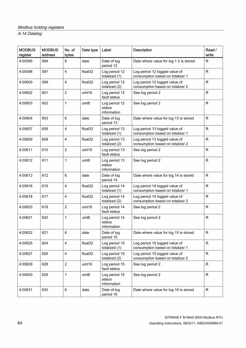
Modbus holding registers A.14 Datalog
SITRANS F M MAG 8000 Modbus RTU 64 Operating Instructions, 08/2011, A5E03409989-01
MODBUS register
MODBUS address
No. of bytes
Data type Label Description Read / write
4:00595 594 6 date Date of log period 12
Date where value for log 1 2 is stored R
4:00598 597 4 float32 Log period 12 totalized (1)
Log period 12 logged value of consumption based on totalizer 1
R
4:00600 599 4 float32 Log period 12 totalized (2)
Log period 12 logged value of consumption based on totalizer 2
R
4:00602 601 2 uint16 Log period 12 fault status
See log period 2 R
4:00603 602 1 uint8 Log period 12 status information
See log period 2 R
4:00604 603 6 date Date of log period 13
Date where value for log 13 is stored R
4:00607 606 4 float32 Log period 13 totalized (1)
Log period 13 logged value of consumption based on totalizer 1
R
4:00609 608 4 float32 Log period 13 totalized (2)
Log period 13 logged value of consumption based on totalizer 2
R
4:00611 610 2 uint16 Log period 13 fault status
See log period 2 R
4:00612 611 1 uint8 Log period 13 status information
See log period 2 R
4:00613 612 6 date Date of log period 14
Date where value for log 14 is stored R
4:00616 615 4 float32 Log period 14 totalized (1)
Log period 14 logged value of consumption based on totalizer 1
R
4:00618 617 4 float32 Log period 14 totalized (2)
Log period 14 logged value of consumption based on totalizer 2
R
4:00620 619 2 uint16 Log period 14 fault status
See log period 2 R
4:00621 620 1 uint8 Log period 14 status information
See log period 2 R
4:00622 621 6 date Date of log period 15
Date where value for log 15 is stored R
4:00625 624 4 float32 Log period 15 totalized (1)
Log period 15 logged value of consumption based on totalizer 1
R
4:00627 626 4 float32 Log period 15 totalized (2)
Log period 15 logged value of consumption based on totalizer 2
R
4:00629 628 2 uint16 Log period 15 fault status
See log period 2 R
4:00630 629 1 uint8 Log period 15 status information
See log period 2 R
4:00631 630 6 date Date of log period 16
Date where value for log 16 is stored R
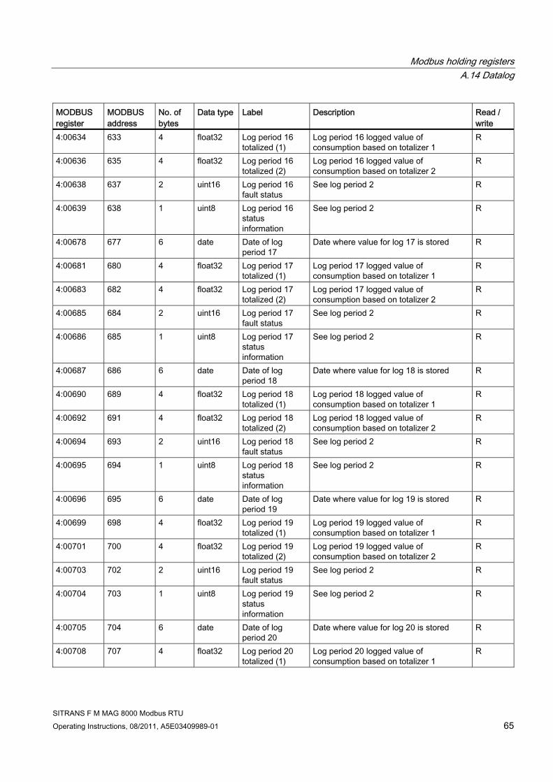
Modbus holding registers A.14 Datalog
SITRANS F M MAG 8000 Modbus RTU Operating Instructions, 08/2011, A5E03409989-01 65
MODBUS register
MODBUS address
No. of bytes
Data type Label Description Read / write
4:00634 633 4 float32 Log period 16 totalized (1)
Log period 16 logged value of consumption based on totalizer 1
R
4:00636 635 4 float32 Log period 16 totalized (2)
Log period 16 logged value of consumption based on totalizer 2
R
4:00638 637 2 uint16 Log period 16 fault status
See log period 2 R
4:00639 638 1 uint8 Log period 16 status information
See log period 2 R
4:00678 677 6 date Date of log period 17
Date where value for log 17 is stored R
4:00681 680 4 float32 Log period 17 totalized (1)
Log period 17 logged value of consumption based on totalizer 1
R
4:00683 682 4 float32 Log period 17 totalized (2)
Log period 17 logged value of consumption based on totalizer 2
R
4:00685 684 2 uint16 Log period 17 fault status
See log period 2 R
4:00686 685 1 uint8 Log period 17 status information
See log period 2 R
4:00687 686 6 date Date of log period 18
Date where value for log 18 is stored R
4:00690 689 4 float32 Log period 18 totalized (1)
Log period 18 logged value of consumption based on totalizer 1
R
4:00692 691 4 float32 Log period 18 totalized (2)
Log period 18 logged value of consumption based on totalizer 2
R
4:00694 693 2 uint16 Log period 18 fault status
See log period 2 R
4:00695 694 1 uint8 Log period 18 status information
See log period 2 R
4:00696 695 6 date Date of log period 19
Date where value for log 19 is stored R
4:00699 698 4 float32 Log period 19 totalized (1)
Log period 19 logged value of consumption based on totalizer 1
R
4:00701 700 4 float32 Log period 19 totalized (2)
Log period 19 logged value of consumption based on totalizer 2
R
4:00703 702 2 uint16 Log period 19 fault status
See log period 2 R
4:00704 703 1 uint8 Log period 19 status information
See log period 2 R
4:00705 704 6 date Date of log period 20
Date where value for log 20 is stored R
4:00708 707 4 float32 Log period 20 totalized (1)
Log period 20 logged value of consumption based on totalizer 1
R

Modbus holding registers A.14 Datalog
SITRANS F M MAG 8000 Modbus RTU 66 Operating Instructions, 08/2011, A5E03409989-01
MODBUS register
MODBUS address
No. of bytes
Data type Label Description Read / write
4:00710 709 4 float32 Log period 20 totalized (2)
Log period 20 logged value of consumption based on totalizer 2
R
4:00712 711 2 uint16 Log period 20 fault status
See log period 2 R
4:00713 712 1 uint8 Log period 20 status information
See log period 2 R
4:00714 713 6 date Date of log period 21
Date where value for log 21 is stored R
4:00717 716 4 float32 Log period 21 totalized (1)
Log period 21 logged value of consumption based on totalizer 1
R
4:00719 718 4 float32 Log period 21 totalized (2)
Log period 21 logged value of consumption based on totalizer 2
R
4:00721 720 2 uint16 Log period 21 fault status
See log period 2 R
4:00722 721 1 uint8 Log period 21 status information
See log period 2 R
4:00723 722 6 date Date of log period 22
Date where value for log 22 is stored R
4:00726 725 4 float32 Log period 22 totalized (1)
Log period 22 logged value of consumption based on totalizer 1
R
4:00728 727 4 float32 Log period 22 totalized (2)
Log period 22 logged value of consumption based on totalizer 2
R
4:00730 729 2 uint16 Log period 22 fault status
See log period 2 R
4:00731 730 1 uint8 Log period 22 status information
See log period 2 R
4:00732 731 6 date Date of log period 23
Date where value for log 23 is stored R
4:00735 734 4 float32 Log period 23 totalized (1)
Log period 23 logged value of consumption based on totalizer 1
R
4:00737 736 4 float32 Log period 23 totalized (2)
Log period 23 logged value of consumption based on totalizer 2
R
4:00739 738 2 uint16 Log period 23 fault status
See log period 2 R
4:00740 739 1 uint8 Log period 23 status information
See log period 2 R
4:00741 740 6 date Date of log period 24
Date where value for log 24 is stored R
4:00744 743 4 float32 Log period 24 totalized (1)
Log period 24 logged value of consumption based on totalizer 1
R
4:00746 745 4 float32 Log period 24 totalized (2)
Log period 24 logged value of consumption based on totalizer 2
R
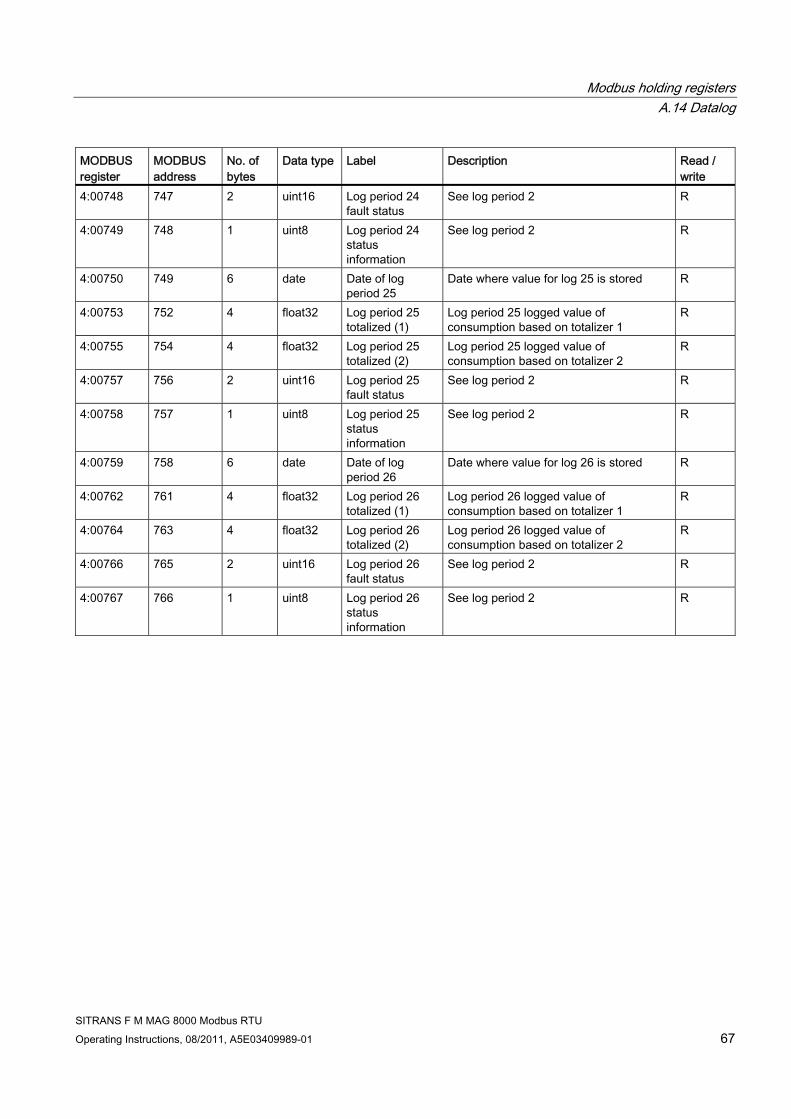
Modbus holding registers A.14 Datalog
SITRANS F M MAG 8000 Modbus RTU Operating Instructions, 08/2011, A5E03409989-01 67
MODBUS register
MODBUS address
No. of bytes
Data type Label Description Read / write
4:00748 747 2 uint16 Log period 24 fault status
See log period 2 R
4:00749 748 1 uint8 Log period 24 status information
See log period 2 R
4:00750 749 6 date Date of log period 25
Date where value for log 25 is stored R
4:00753 752 4 float32 Log period 25 totalized (1)
Log period 25 logged value of consumption based on totalizer 1
R
4:00755 754 4 float32 Log period 25 totalized (2)
Log period 25 logged value of consumption based on totalizer 2
R
4:00757 756 2 uint16 Log period 25 fault status
See log period 2 R
4:00758 757 1 uint8 Log period 25 status information
See log period 2 R
4:00759 758 6 date Date of log period 26
Date where value for log 26 is stored R
4:00762 761 4 float32 Log period 26 totalized (1)
Log period 26 logged value of consumption based on totalizer 1
R
4:00764 763 4 float32 Log period 26 totalized (2)
Log period 26 logged value of consumption based on totalizer 2
R
4:00766 765 2 uint16 Log period 26 fault status
See log period 2 R
4:00767 766 1 uint8 Log period 26 status information
See log period 2 R

Modbus holding registers A.15 Consumption readings
SITRANS F M MAG 8000 Modbus RTU 68 Operating Instructions, 08/2011, A5E03409989-01
A.15 Consumption readings
Table A- 16 Consumption readings
MODBUS register
MODBUS address
No. of bytes
Data type Label Description Read / write
4:00144 143 1 uint8 Actual flow meter status
One byte describing actual status • Bit 1: Totalizer 1 or 2 changed or reset • Bit 2: Tariff setting changed or reset • Bit 3: Tariff register changed or reset • Bit 4: Date - time changed • Bit 5: Alarm active • Bit 6: Fault log has been reset • Bit 7: HW lock broken • Bit 8: Power Up
R
4:00145 144 6 SettlingDate
Next settling date
Next automatically settling date where actual value of totalizer 1 is stored
R/W
4:00148 147 6 date Latest settling date
Latest settling date where value of totalizer 1 was stored
R
4:00151 150 8 totaltype Latest totalizer 1 value
Latest stored value of totalizer 1 R
4:00155 154 6 date Previous settling date
Previous settling date where value of totalizer 1 was stored
R
4:00158 157 8 totaltype Previous totalizer 1 value
Previous stored value of totalizer 1 R
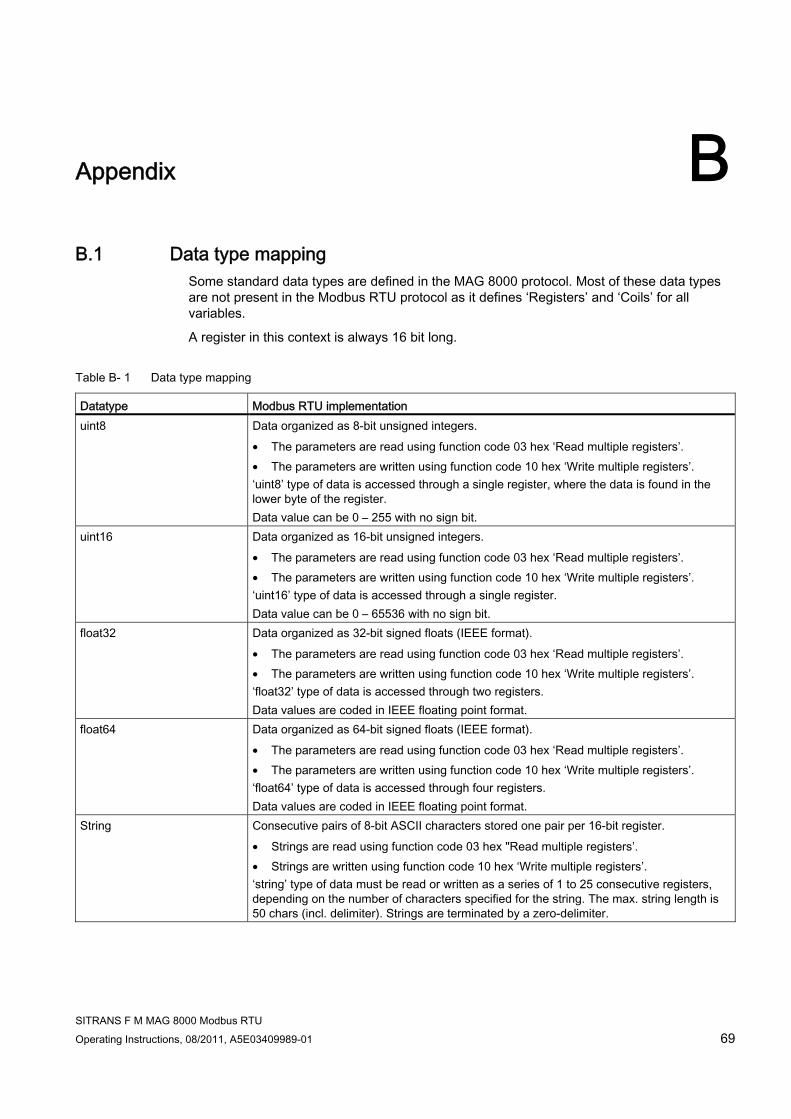
SITRANS F M MAG 8000 Modbus RTU Operating Instructions, 08/2011, A5E03409989-01 69
Appendix BB.1 Data type mapping
Some standard data types are defined in the MAG 8000 protocol. Most of these data types are not present in the Modbus RTU protocol as it defines ‘Registers’ and ‘Coils’ for all variables.
A register in this context is always 16 bit long.
Table B- 1 Data type mapping
Datatype Modbus RTU implementation uint8 Data organized as 8-bit unsigned integers.
• The parameters are read using function code 03 hex ‘Read multiple registers’. • The parameters are written using function code 10 hex ‘Write multiple registers’. ‘uint8’ type of data is accessed through a single register, where the data is found in the lower byte of the register. Data value can be 0 – 255 with no sign bit.
uint16 Data organized as 16-bit unsigned integers. • The parameters are read using function code 03 hex ‘Read multiple registers’. • The parameters are written using function code 10 hex ‘Write multiple registers’. ‘uint16’ type of data is accessed through a single register. Data value can be 0 – 65536 with no sign bit.
float32 Data organized as 32-bit signed floats (IEEE format). • The parameters are read using function code 03 hex ‘Read multiple registers’. • The parameters are written using function code 10 hex ‘Write multiple registers’. ‘float32’ type of data is accessed through two registers. Data values are coded in IEEE floating point format.
float64 Data organized as 64-bit signed floats (IEEE format). • The parameters are read using function code 03 hex ‘Read multiple registers’. • The parameters are written using function code 10 hex ‘Write multiple registers’. ‘float64’ type of data is accessed through four registers. Data values are coded in IEEE floating point format.
String Consecutive pairs of 8-bit ASCII characters stored one pair per 16-bit register. • Strings are read using function code 03 hex "Read multiple registers’. • Strings are written using function code 10 hex ‘Write multiple registers’. ‘string’ type of data must be read or written as a series of 1 to 25 consecutive registers, depending on the number of characters specified for the string. The max. string length is 50 chars (incl. delimiter). Strings are terminated by a zero-delimiter.

Appendix B.2 CRC calculation
SITRANS F M MAG 8000 Modbus RTU 70 Operating Instructions, 08/2011, A5E03409989-01
Datatype Modbus RTU implementation TotalType Data type defined by Siemens mainly used for Totalizer values. TotalType consist of two
parts: 1. signed long Number - contains the integer part of Value 2. signed long Decimal – contains the fractional part of the Value multiplied with 1.0E9 • The parameters are read using function code 03 hex ‘Read multiple registers’. • The parameters are written using function code 10 hex ‘Write multiple registers’.
Date Data type defined by Siemens used for dates. Date consist of 6 parts: 1. Unsigned Char Year 2. Unsigned Char Month 3. Unsigned Char Day 4. Unsigned Char Hour 5. Unsigned Char Minute 6. Unsigned Char Second • The parameters are read using function code 03 hex ‘Read multiple registers’. • The parameters are written using function code 10 hex ‘Write multiple registers’.
B.2 CRC calculation The Cyclical Redundancy Checking (CRC) field is two bytes, containing a 16–bit binary value. The CRC value is first generated by the transmitting device, which appends the CRC to the message. The receiving device recalculates a CRC during receipt of the message, and compares the calculated value to the actual value it received in the CRC field. If the two values are not equal an error occurs.
In the following a short text description of how the CRC is calculated is provided. This description is then followed by a C programming example.
CRC calculation 1. Load a 16–bit register with FFFF hex (all 1’s). Call this the CRC register.
2. Exclusive OR the first 8–bit byte of the message with the low–order byte of the 16–bit CRC register, putting the result in the CRC register.
3. Shift the CRC register one bit to the right (toward the LSB), zero–filling the MSB. Extract and examine the LSB.
4. (If the LSB was 0): Repeat Step 3 (another shift). (If the LSB was 1): Exclusive OR the CRC register with the polynomial value 0xA001 (1010 0000 0000 0001).
5. Repeat Steps 3 and 4 until 8 shifts have been performed. When this is done, a complete 8–bit byte will have been processed.
6. Repeat Steps 2 through 5 for the next 8–bit byte of the message. Continue doing this until all bytes have been processed.
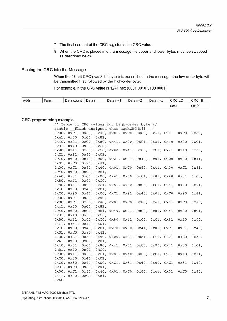
Appendix B.2 CRC calculation
SITRANS F M MAG 8000 Modbus RTU Operating Instructions, 08/2011, A5E03409989-01 71
7. The final content of the CRC register is the CRC value.
8. When the CRC is placed into the message, its upper and lower bytes must be swapped as described below.
Placing the CRC into the Message When the 16–bit CRC (two 8–bit bytes) is transmitted in the message, the low-order byte will be transmitted first, followed by the high-order byte.
For example, if the CRC value is 1241 hex (0001 0010 0100 0001):
Addr Func Data count Data n Data n+1 Data n+2 Data n+x CRC LO CRC HI 0x41 0x12
CRC programming example /* Table of CRC values for high-order byte */ static __flash unsigned char auchCRCHi[] = { 0x00, 0xC1, 0x81, 0x40, 0x01, 0xC0, 0x80, 0x41, 0x01, 0xC0, 0x80, 0x41, 0x00, 0xC1, 0x81, 0x40, 0x01, 0xC0, 0x80, 0x41, 0x00, 0xC1, 0x81, 0x40, 0x00, 0xC1, 0x81, 0x40, 0x01, 0xC0, 0x80, 0x41, 0x01, 0xC0, 0x80, 0x41, 0x00, 0xC1, 0x81, 0x40, 0x00, 0xC1, 0x81, 0x40, 0x01, 0xC0, 0x80, 0x41, 0x00, 0xC1, 0x81, 0x40, 0x01, 0xC0, 0x80, 0x41, 0x01, 0xC0, 0x80, 0x41, 0x00, 0xC1, 0x81, 0x40, 0x01, 0xC0, 0x80, 0x41, 0x00, 0xC1, 0x81, 0x40, 0x00, 0xC1, 0x81, 0x40, 0x01, 0xC0, 0x80, 0x41, 0x00, 0xC1, 0x81, 0x40, 0x01, 0xC0, 0x80, 0x41, 0x01, 0xC0, 0x80, 0x41, 0x00, 0xC1, 0x81, 0x40, 0x00, 0xC1, 0x81, 0x40, 0x01, 0xC0, 0x80, 0x41, 0x01, 0xC0, 0x80, 0x41, 0x00, 0xC1, 0x81, 0x40, 0x01, 0xC0, 0x80, 0x41, 0x00, 0xC1, 0x81, 0x40, 0x00, 0xC1, 0x81, 0x40, 0x01, 0xC0, 0x80, 0x41, 0x01, 0xC0, 0x80, 0x41, 0x00, 0xC1, 0x81, 0x40, 0x00, 0xC1, 0x81, 0x40, 0x01, 0xC0, 0x80, 0x41, 0x00, 0xC1, 0x81, 0x40, 0x01, 0xC0, 0x80, 0x41, 0x01, 0xC0, 0x80, 0x41, 0x00, 0xC1, 0x81, 0x40, 0x00, 0xC1, 0x81, 0x40, 0x01, 0xC0, 0x80, 0x41, 0x01, 0xC0, 0x80, 0x41, 0x00, 0xC1, 0x81, 0x40, 0x01, 0xC0, 0x80, 0x41, 0x00, 0xC1, 0x81, 0x40, 0x00, 0xC1, 0x81, 0x40, 0x01, 0xC0, 0x80, 0x41, 0x00, 0xC1, 0x81, 0x40, 0x01, 0xC0, 0x80, 0x41, 0x01, 0xC0, 0x80, 0x41, 0x00, 0xC1, 0x81, 0x40, 0x01, 0xC0, 0x80, 0x41, 0x00, 0xC1, 0x81, 0x40, 0x00, 0xC1, 0x81, 0x40, 0x01, 0xC0, 0x80, 0x41, 0x01, 0xC0, 0x80, 0x41, 0x00, 0xC1, 0x81, 0x40, 0x00, 0xC1, 0x81, 0x40, 0x01, 0xC0, 0x80, 0x41, 0x00, 0xC1, 0x81, 0x40, 0x01, 0xC0, 0x80, 0x41, 0x01, 0xC0, 0x80, 0x41, 0x00, 0xC1, 0x81, 0x40

Appendix B.2 CRC calculation
SITRANS F M MAG 8000 Modbus RTU 72 Operating Instructions, 08/2011, A5E03409989-01
} ; /* Table of CRC values for low-order byte */ static __flash char auchCRCLo[] = { 0x00, 0xC0, 0xC1, 0x01, 0xC3, 0x03, 0x02, 0xC2, 0xC6, 0x06, 0x07, 0xC7, 0x05, 0xC5, 0xC4, 0x04, 0xCC, 0x0C, 0x0D, 0xCD, 0x0F, 0xCF, 0xCE, 0x0E, 0x0A, 0xCA, 0xCB, 0x0B, 0xC9, 0x09, 0x08, 0xC8, 0xD8, 0x18, 0x19, 0xD9, 0x1B, 0xDB, 0xDA, 0x1A, 0x1E, 0xDE, 0xDF, 0x1F, 0xDD, 0x1D, 0x1C, 0xDC, 0x14, 0xD4, 0xD5, 0x15, 0xD7, 0x17, 0x16, 0xD6, 0xD2, 0x12, 0x13, 0xD3, 0x11, 0xD1, 0xD0, 0x10, 0xF0, 0x30, 0x31, 0xF1, 0x33, 0xF3, 0xF2, 0x32, 0x36, 0xF6, 0xF7, 0x37, 0xF5, 0x35, 0x34, 0xF4, 0x3C, 0xFC, 0xFD, 0x3D, 0xFF, 0x3F, 0x3E, 0xFE, 0xFA, 0x3A, 0x3B, 0xFB, 0x39, 0xF9, 0xF8, 0x38, 0x28, 0xE8, 0xE9, 0x29, 0xEB, 0x2B, 0x2A, 0xEA, 0xEE, 0x2E, 0x2F, 0xEF, 0x2D, 0xED, 0xEC, 0x2C, 0xE4, 0x24, 0x25, 0xE5, 0x27, 0xE7, 0xE6, 0x26, 0x22, 0xE2, 0xE3, 0x23, 0xE1, 0x21, 0x20, 0xE0, 0xA0, 0x60, 0x61, 0xA1, 0x63, 0xA3, 0xA2, 0x62, 0x66, 0xA6, 0xA7, 0x67, 0xA5, 0x65, 0x64, 0xA4, 0x6C, 0xAC, 0xAD, 0x6D, 0xAF, 0x6F, 0x6E, 0xAE, 0xAA, 0x6A, 0x6B, 0xAB, 0x69, 0xA9, 0xA8, 0x68, 0x78, 0xB8, 0xB9, 0x79, 0xBB, 0x7B, 0x7A, 0xBA, 0xBE, 0x7E, 0x7F, 0xBF, 0x7D, 0xBD, 0xBC, 0x7C, 0xB4, 0x74, 0x75, 0xB5, 0x77, 0xB7, 0xB6, 0x76, 0x72, 0xB2, 0xB3, 0x73, 0xB1, 0x71, 0x70, 0xB0, 0x50, 0x90, 0x91, 0x51, 0x93, 0x53, 0x52, 0x92, 0x96, 0x56, 0x57, 0x97, 0x55, 0x95, 0x94, 0x54, 0x9C, 0x5C, 0x5D, 0x9D, 0x5F, 0x9F, 0x9E, 0x5E, 0x5A, 0x9A, 0x9B, 0x5B, 0x99, 0x59, 0x58, 0x98, 0x88, 0x48, 0x49, 0x89, 0x4B, 0x8B, 0x8A, 0x4A, 0x4E, 0x8E, 0x8F, 0x4F, 0x8D, 0x4D, 0x4C, 0x8C, 0x44, 0x84, 0x85, 0x45, 0x87, 0x47, 0x46, 0x86, 0x82, 0x42, 0x43, 0x83, 0x41, 0x81, 0x80, 0x40 } ; unsigned short int CRC16(unsigned char *puchMsg, unsigned short int usDataLen) { unsigned char uchCRCHi = 0xFF; /* high byte of CRC initialized */ unsigned char uchCRCLo = 0xFF; /* low byte of CRC initialized */ unsigned uIndex ; /* will index into CRC lookup table */ while(usDataLen--) /* pass through message buffer */ { uIndex = uchCRCHi ^ *puchMsg++ ; /* calculate the CRC */ uchCRCHi = uchCRCLo ^ auchCRCHi[uIndex] ; uchCRCLo = auchCRCLo[uIndex] ; } #ifdef INTEL_LIKE_PROCESSOR

Appendix B.2 CRC calculation
SITRANS F M MAG 8000 Modbus RTU Operating Instructions, 08/2011, A5E03409989-01 73
return (unsigned short int)((uchCRCLo << 8) | uchCRCHi); #else return (unsigned short int)((uchCRCHi << 8) | uchCRCLo); #endif }
See also There are many ways of calculating a CRC checksum. For further information, please refer to the Modbus Organisation Website (http://www.modbus.org/) , where detailed descriptions and programming examples are available.

Appendix B.2 CRC calculation
SITRANS F M MAG 8000 Modbus RTU 74 Operating Instructions, 08/2011, A5E03409989-01
SITRANS F M MAG 8000 Modbus RTU Operating Instructions, 08/2011, A5E03409989-01 75
Glossary
CRC Cyclic Redundancy Check. Used for error-checking in Modbus RTU
Modbus master A Modbus device, which is able to access data in one or more connected Modbus slaves.
Modbus slave A Modbus device, which is able to respond to requests from a single Modbus master.
RS232 Refers to communication standard defined by EIA/TIA-232 (Physical layer).
RS485 Refers to communication standard defined by EIA/TIA-485 (Physical layer).

Glossary
SITRANS F M MAG 8000 Modbus RTU 76 Operating Instructions, 08/2011, A5E03409989-01
SITRANS F M MAG 8000 Modbus RTU Operating Instructions, 08/2011, A5E03409989-01 77
Index
A Application settings, 40
B Baudrate, 18
C Cable specifications, 13 Commissioning
Steps, 19 with PDM, 19
Communication modes, 7 Communication parameters, 18
Setup, 21 Configuring the device, 22 Consumption profile, 56 Consumption readings, 68 Consumption statistic, 55 Contact person, 8 Customer profile, 40
D Data type mapping, 69 Datalog, 59 Device
Address, 17 Name, 17
Document history, 5 Driver settings, 41
E EDD files
Download, 20 Installation, 20
Electrical connection General instructions, 13 Shielding, 13
Error messages, 47 Ex Approval, 9
Exception codes, 35
F Function codes, 25
H Hardware lock, 18 Hazardous areas, 9
I Installation
Hardware, 11 Internet
Contact person, 8 Flowdocumentation, 8 Modbus Organisation, 8
L Leakage statistic, 57
M Measurement, 40 Menu control, 42 Modbus
Features, 6 Frame, 7 Network, 21 Organisation Website, 8 Technology, 6
Modbus addressing model, 25
O Operation, 24
P Parameter access, 19 Parameterization, 22 PDM

Index
SITRANS F M MAG 8000 Modbus RTU 78 Operating Instructions, 08/2011, A5E03409989-01
Commissioning, 19 Commissioning steps, 19
Power control, 53 Pulse output, 45
R Read coils, 26 Read multiple register, 28 Report Slave ID, 34
S Safety notes, 9 Sensor characteristics, 43 Service control, 47 System integration, 17
T Totalization, 40, 45
W Wiring, 14
Bus termination, 15 RS232 connection diagram, 14 RS485 connection diagram, 14
Write coil, 30 Write protection, 18

www.siemens.com/processautomation
Siemens A/S Flow InstrumentsNordborgvej 81DK-6430 Nordborg
Subject to change without prior noticeOrder No.: A5E03409989Lit. No.: A5E03409989-01 © Siemens AG 08.2011
For more information
www.siemens.com/flow
*A5E03409989*