sitrans f m magflo sitrans f c massflo - siemens · resistance < 110 ohm per km signal...
TRANSCRIPT

Order no.: FDK:521H1185
SFIDK.PS.023.B2.02
SITRANS F M MAGFLO®®®®® &SITRANS F C MASSFLO®®®®®
Profibus DP Profile 2 add-on module forUSM II transmitters FDK:085U0230
[ ]
s
Technical Documentation (handbooks, instructions, manuals etc.) on the complete productrange SITRANS F can be found on the internet/intranet on the following links:
English: http://www4.ad.siemens.de/WW/view/en/10806951/133300
Operating ManualEdition 01/2004 - Revision 02
A5E00753971

2 SFIDK.PS.023.B2.02
Profibus DP add-on module
Contents 1. Introduction .................................................................................................................... 3
2. Technical data ............................................................................................................... 3
3. Installation ..................................................................................................................... 53.1 Add-on module .............................................................................................................. 53.2 General connections ..................................................................................................... 63.3 Profibus connection ...................................................................................................... 63.4 Termination .................................................................................................................... 6
4. Commissioning ............................................................................................................. 74.1 Profibus display menu .................................................................................................. 74.2 Menu item explanation .................................................................................................. 84.3 GSD files ....................................................................................................................... 84.4 Configuration of cyclic DataExchange.......................................................................... 84.4.1 Input data (Master view) ................................................................................................ 94.4.2 Output data (Master view) ........................................................................................... 104.5 Configuration with STEP 7 .......................................................................................... 124.6 Configuration with PDM .............................................................................................. 14
5. Diagnostics .................................................................................................................. 155.1 Standard diagnostics ..................................................................................................155.2 Extended diagnostics ..................................................................................................15
6. Profile description ....................................................................................................... 166.1 Data management within the Profibus DP module .................................................... 166.2 SITRANS F M MAGFLO® Slot/index diagram ............................................................ 166.3 SITRANS F C MASSFLO® Slot/index diagram ........................................................... 176.4 Slot/index description ..................................................................................................186.4.1 Device management ................................................................................................... 186.4.2 Physical block ............................................................................................................. 186.4.3 Analog input function block ......................................................................................... 196.4.4 Flow transducer block ................................................................................................. 206.4.5 Transducer blocks, (SITRANS F C MASSFLO® only) ................................................ 226.4.6 Totalizers ..................................................................................................................... 226.4.7 Batch ........................................................................................................................... 246.4.8 Status log transducer block ......................................................................................... 256.4.9 Error pending transducer block .................................................................................. 25
APPENDIX A ..........................................................................................................................26Profibus data structures .............................................................................................. 26Data structures ............................................................................................................ 26DS-33 Value & status ................................................................................................... 26DS-36 Scaling ............................................................................................................. 26DS-39 Alarm float ........................................................................................................26DS-50 Simulation float ................................................................................................ 26
APPENDIX B ..........................................................................................................................27Coding of physical block diagnostics ......................................................................... 27
APPENDIX C ..........................................................................................................................27SI-Units used in USM II products ................................................................................27
APPENDIX DBatching with Profibus ................................................................................................ 28Cyclic Batch control ..................................................................................................... 29
Profibus DP add-on module
3SFIDK.PS.023.B2.02
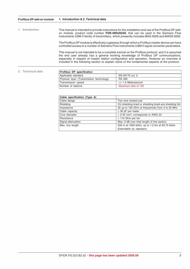
This manual is intended to provide instructions for the installation and use of the Profibus DP add-on module, product code number FDK:085U0230, that can be used in the Siemens FlowInstruments USM II family of transmitters, which presently includes MAG 6000 and MASS 6000.
The Profibus DP module is effectively a gateway through which a Profibus master device can havecontrolled access to a number of Siemens Flow Instruments USM II signal converter parameters.
This manual is not intended to be a complete tutorial on the Profibus protocol, and it is assumedthe end user already has a general working knowledge of Profibus DP communications,especially in respect of master station configuration and operation. However an overview isincluded in the following section to explain some of the fundamental aspects of the protocol.
1. Introduction
2. Technical data Profibus DP specificationApplicable standard EN 50170 vol. 2Physical layer (Transmission technology) RS 485Transmission speed <= 1.5 Mbits/secondNumber of stations Maximum total of 126
Cable specification (Type A)Cable design Two wire twisted pairShielding CU shielding braid or shielding braid and shielding foilImpedance 35 up to 165 Ohm at frequencies from 3 to 20 MhzCable capacity < 30 pF per meterCore diameter > 0.34 mm², corresponds to AWG 22Resistance < 110 Ohm per kmSignal attenuation Max. 9 dB over total length of line sectionMax. bus length 200 m at 1500 kbit/s, up to 1.2 km at 93.75 kbit/s
Extendable by repeaters
1. Introduction & 2. Technical data
- this page has been updated 2006.09

4 SFIDK.PS.023.B2.02
Profibus DP add-on module 2. Technical data
Input (Master view) USM II parameter MAG 6000 MASS 6000(1) Requires a SENSORPROM® Mass flow √√√√√
unit containing valid fraction data. Volume flow √√√√√ √√√√√(2) Value returned is dependent on Temperature √√√√√
the batch function. When ON, Density √√√√√batch progress is returned. Fraction A (1) √√√√√When OFF, totalizer 2 Fraction B (1) √√√√√is returned.
Pct Fraction A (1) √√√√√Totalizer 1 √√√√√ √√√√√Totalizer 2 (2) √√√√√ √√√√√Batch progress (2) √√√√√ √√√√√
Output (Master view) Totalizer control (hold/reset) √√√√√ √√√√√Batch control (start, stop…) √√√√√ √√√√√Batch set-point √√√√√ √√√√√Batch compensation √√√√√ √√√√√
Cyclic services
Device profile Version 2.0, Class BFlow transducer block parameter Class 01 Electromagnetic (MAG 6000)sets supported Class 03 Coriolis (MASS 6000)
USM II parameter MAG 6000 MASS 6000(3) In the Profibus Totalizer Reset √√√√√ √√√√√
flow transducer Direction √√√√√ √√√√√block this is called Process Units √√√√√ √√√√√the sample rate variables Time constant √√√√√ √√√√√
Alarm set-points √√√√√ √√√√√Batch On/Off √√√√√ √√√√√control Set-point √√√√√ √√√√√
Cycle counter √√√√√ √√√√√Cycle counter reset √√√√√ √√√√√Mode: Start √√√√√ √√√√√
Pause √√√√√ √√√√√Resume √√√√√ √√√√√Stop √√√√√ √√√√√
Maximum batch time √√√√√ √√√√√Batch compensation √√√√√ √√√√√
General Sensor size √√√√√ √√√√√Calibration factor √√√√√ √√√√√Zero point value √√√√√Flow direction √√√√√ √√√√√Scale upper √√√√√ √√√√√Scale lower √√√√√ √√√√√Broadcast interval (3) √√√√√ √√√√√Low flow cut-off √√√√√ √√√√√
System Zero point adjust: Auto √√√√√Manual √√√√√
Set to default √√√√√ √√√√√Error Log/ Error pending √√√√√ √√√√√Pending Status log list √√√√√ √√√√√
Reset status list √√√√√ √√√√√
Acyclic services
Profibus DP add-on module
5SFIDK.PS.023.B2.02
3. Installation
3. Installation
3.1 Add-on module19” rack mounted versions IP 67 compact versions
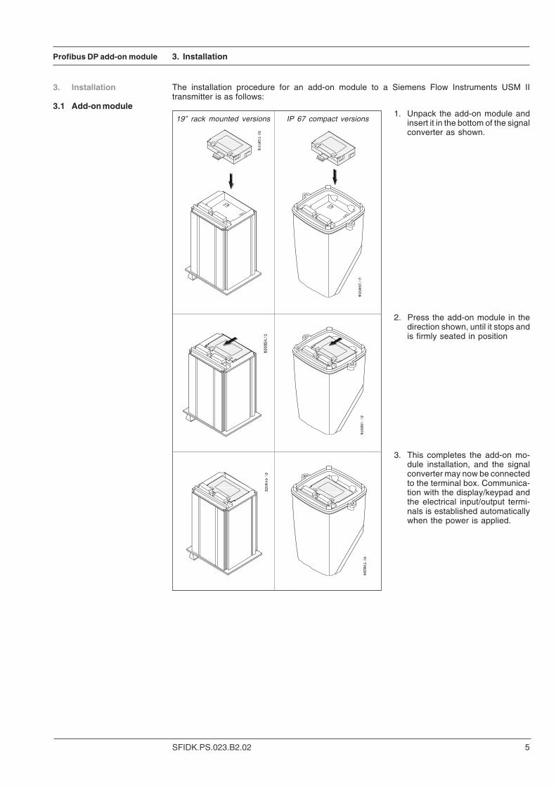
The installation procedure for an add-on module to a Siemens Flow Instruments USM IItransmitter is as follows:
1. Unpack the add-on module andinsert it in the bottom of the signalconverter as shown.
2. Press the add-on module in thedirection shown, until it stops andis firmly seated in position
3. This completes the add-on mo-dule installation, and the signalconverter may now be connectedto the terminal box. Communica-tion with the display/keypad andthe electrical input/output termi-nals is established automaticallywhen the power is applied.

6 SFIDK.PS.023.B2.02
Profibus DP add-on module 3. Installation
3.2 General connections
3.3 Profibus connection
On the electrical termination boards for USM II transmitters, additional input/output terminals havebeen reserved for add-on module functions. The numbering range of these terminals is as follows,but how many are actually used depends on the type of add-on module. Please refer to therelevant handbook for other electrical connection information.
Additional terminals reserved for add-on modules:MAG 6000: 91 - 97MASS 6000: 91 - 100
NoteThe standard inputs and outputs continue to function and are not affected by the presence of anadd-on module. Any existing transmitter electrical connections can remain undisturbed.
All RS 485 based networks must be terminated correct to function properly. A termination mustbe placed at each end of the segment.The Profibus module can add a termination by connecting terminals 91 to 92 and 93 to 94.It is important to use very short wires for this connection.
3.4 Termination

Profibus DP add-on module
7SFIDK.PS.023.B2.02
4. Commissioning
4. Commissioning Before communicating with the Master, the device address must be selected. This can be doneeither from the display or from the commissioning software. Please look in to the transmittermanual to locate the Profibus DP module menu.
4.1 Profibus display menu
To change (or view) the Profibus settings from the keypad display.
1. Press [Top key] for two seconds. (NOTE: For “View” mode only, skip steps 2 & 3).
2. Type in password (1000) by pressing [Change key] two times, and then press
[Lock key] and hold for two seconds
3. The display now says “Basic settings”
4. Press [Forward key] until you reach the “Profibus DP module” menu item
5. Press [Lock key]
6. You can now cycle through all the Profibus DP settings by pressing [Forward key]
7. Select “PROFI address”
8. Type in the address with the [Change key] and [Next key]
9. Lock the setting with the [Lock key]
10. Press [Top key] for two seconds and you return to 1.

8 SFIDK.PS.023.B2.02
Profibus DP add-on module 4. Commissioning
Below the submenus under the main menu „Profibus DP module“ are described:4.2 Menu item explanation
SENSORPROM®®®®® flow memory unitAll of the Profibus DP settings are stored in the add-on module in non-volatile memory.
They are not stored in the SENSORPROM®®®®® unit.This means that if the DP module is exchanged for another DP module, all of the relevant ProfibusDP settings will need to be downloaded from the DPM2 master to the device. This also appliesto the Profibus station address, which may be entered via the keypad/display on the flowmeter,or alternatively via the bus, if the master supports changing the station address. Please note thatthe above only applies to the Profibus DP settings. All other flowmeter settings are stored in theSENSORPROM® unit.
Item Value DescriptionPROFI address 0-126 Device address [Factory setting: 126]
Address number 126 cannot be selected. Thisaddress means new device and is programmed fromfactory.
TAG name String 0-32 bytes Can be used to TAG the device. Master class 2 isneeded to change the TAG name.
TAG descriptor String 0-32 bytes Can be used to describe the TAG. Master class 2 isneeded to change the TAG descriptor.[Default: „Flowmeter“]
TAG date 8 bytes Can be used to date the installation. Master class 2 isneeded to change the TAG descriptor.[Default: „None“]
PROFISW version x.xx Firmware version of the Profibus module.Comm status This menu can be used in service cases. It displays the
state of the device. Following modes are possible:Offline The device cannot see a master. Either the
master is turned off or poor cabling.Online A master is detected, but the device is
not configured.Data The device is configured and up andExchange running.Timeout The device has been configured, but
the watchdog has timed out. Possible error:The master was disconnected.
A GSD file is needed to be able to configure the master. The GSD file describes what a devicecan do and what it supports. Some software tools support integration of an individual image ofthe device. Such image is in the bitmap format and has the extension .BMP.
Following GSD files must be used with this device:
Flowmeter GSD file BMP fileMAG 6000 SIxx05a9.gsd SI05a9n.bmpMASS 6000 SIxx05A8.gsd SI05a8n.bmp
Note: xx is the revision of the GSD file.
GSD files and BMP files can be downloadedfrom the Siemens homepage.
4.3 GSD files

Profibus DP add-on module
9SFIDK.PS.023.B2.02
4.4.1 Input data(Master view)
All variables in the input area are 5 bytes in size - a 4-byte float and a statusbyte. The structureof the status-byte is described in Appendix A in the table called “DS-33 Value and Status”.
MAGFLO input data orderSlot order Name Configuration value Description
[hex] [dec]1 Volumeflow 0x94 148 5 bytes (float + status)2 Totalizer 1 0x94 148 5 bytes (float + status)3 Totalizer 2 / Batch 0x94 148 5 bytes (float + status)
4. Commissioning
If any of the input variables are not to be used, the “Empty Slot” can be used instead. This reducesthe data load on the bus, and the Masters use of address spacing. The “Empty Slot” is includedin the GSD file.
NoteAll valves are in basic SI-units according to appendix C.
MASSFLO input data orderSlot order Name Configuration value Description
[hex] [dec]1 Massflow 0x94 148 5 bytes (float + status)2 Volumeflow 0x94 148 5 bytes (float + status)3 Density 0x94 148 5 bytes (float + status)4 Temperature 0x94 148 5 bytes (float + status)5 Fraction A 0x94 148 5 bytes (float + status)6 Fraction B 0x94 148 5 bytes (float + status)7 Pct. Fraction A 0x94 148 5 bytes (float + status)8 Totalizer 1 0x94 148 5 bytes (float + status)9 Totalizer 2 / Batch 0x94 148 5 bytes (float + status)
A central controller that cyclically exchanges data with slave devices on a Profibus network iscalled a Master class 1 device. The master uses a GSD file in order to determine which datacan be exchanged. The order of the data in the cyclic message is the same as in the GSD file.
4.4 Configuration ofcyclic DataExchange
- this page has been updated 01-2005

10 SFIDK.PS.023.B2.02
Profibus DP add-on module
Totalizer controlThis control consists of 1 Byte.
Bit 7 6 5 4 3 2 1 0Function ZA T2H T1H T2R T1R
T1R = Totalizer 1 resetT2R = Totalizer 2 resetT1H = Totalizer 1 hold/runT2H = Totalizer 2 hold/runZA = Zero adjust
The action takes place when the bit changes from 0 to 1, except for T1H and T2H which are inhold mode when the bit is 1 and in run mode when the bit is 0.
Batch controlThis control consists of 1 Byte.
Bit 7 6 5 4 3 2 1 0Function BOFM BOF USC BSTP BSRT
BSRT = Batch startBSTP = Batch stopUSC = Update set-point and compensationBOF = Batch ON/OFF (1 = ON; 0 = OFF)BOFM = Batch ON/OFF MASK (1 = BOF will be detected; 0 = BOF will NOT be detected)
The actions takes place when the bit changes from 0 to 1.
4. Commissioning
To ensure 100% detection of the bit combinations, the bit change must be active for a minimum of 100mS.
4.4.2 Output data(Master view)
To be able to control the most common functions via cyclic communication, 4 output blocks areavailable.
If any of the output blocks are not to be used, the “Empty Slot” can be used instead. This reducesthe data load on the bus, and the Masters use of address spacing. The “Empty Slot” is includedin the GSD file.
MAGFLO & MASSFLO output data orderConfiguration
Slot order Name value Description[hex] [dec]
MAGFLO MASSFLO4 10 Totalizer control 0xA0 160 1 byte5 11 Batch control 0xA0 160 1 byte6 12 Setpoint or 0xA4 164 5 bytes (float + status)
Setpoint (Not PCS7) 0xA3 163 4 bytes (float)7 13 Compensation or 0xA4 164 5 bytes (float + status)
Compensation (Not PCS7) 0xA3 163 4 bytes (float)

Profibus DP add-on module
11SFIDK.PS.023.B2.02
Byte 3 2 1 0Parameter Set-point (Float)
Byte 3 2 1 0Parameter Compensation (Float)
Byte 4 3 2 1 0Parameter Status Set-point (Float)
Byte 4 3 2 1 0Parameter Status Compensation (Float)
4. Commissioning
Version 1.04 of the Profibus module can be configured with the format 0xA3 illustrated above,but also with the format 0xA4 will be accepted in version 1.04. The format 0xA4 consists of onefloat and a status byte, as illustrated below.
If the status of either the setpoint or compensation is bad or uncertain, then the correspondingvalue will not be updated in the flowmeter. This means that the parameters only will be acceptedif status equals 0x80 or any other value in the category „Good“.
BatchSet-point and compensation:Two different configuration formats of set-point and compensation are available. Either theformat: float (4 bytes) or float + status (5 bytes).
In Profibus modules firmware version 1.03 and earlier versions, the batch set-point andcompensation have the format 0xA3. This format consists of one float and is illustrated below forboth set-point and compensation. This format does not comply with PCS7.
Please refer to Appendix D for a detailed description of which steps to take when Batching.

12 SFIDK.PS.023.B2.02
Profibus DP add-on module 4. Commissioning
4.5 Configuration withSTEP 7
MAG 6000In this example only „Volume flow“, „Totalizer 1“ and „Totalizer control“ are configured. Theothers are left out, by using the „Empty Slot“.The order must be the same as in the GSD file. This means that it is not possible to place „Totalizer1“ in SLOT 1 and „Volume flow“ in SLOT 2.
The following examples are from a Siemens STEP 7 project, and demonstrates the use of „Emptymodule“.In STEP 7 SFC14 should be used for the reading of process values.
- this page has been updated 01-2005

Profibus DP add-on module
13SFIDK.PS.023.B2.02
4. Commissioning
MASS 6000In this example only „Massflow“, „Temperature“, „Totalizer 2/Batch“, „Batch control“ and„Batch Set-point“ are configured. The others are left out, by using the „Empty Slot“.The order must be the same as in the GSD file. This means that it is not possible to e.g. place„Temperature“ in SLOT 1 and „Massflow“ in SLOT 4.
- this page has been updated 01-2005
14 SFIDK.PS.023.B2.02
Profibus DP add-on module 4. Commissioning
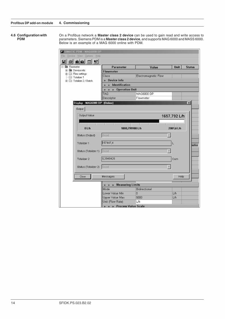
4.6 Configuration withPDM
On a Profibus network a Master class 2 device can be used to gain read and write access toparameters. Siemens PDM is a Master class 2 device, and supports MAG 6000 and MASS 6000.Below is an example of a MAG 6000 online with PDM.

Profibus DP add-on module
15SFIDK.PS.023.B2.02
5. Diagnostics
5. Diagnostics The Profibus slave has the capability of sending diagnostics data, if required. The diagnosticsdata is split up into, Standard diagnostics and Extended diagnostics.The diagnostics data consists of 23 bytes in total. The first 6 bytes are the Standard DPdiagnostics, and the last 17 Bytes are Extended diagnostics.
5.1 Standard diagnostics Byte 1 2 3 4 5 6Value D1 D2 D3 DM IH IL
D1: First diagnostic byteBit 0: Diag.station does not exist (set by Master)Bit 1: Diag.Station_not _ready. Slave is not ready for data exchangeBit 2: Diag.cfg_Fault. Configuration from master is not validBit 3: Diag.ext_diag. Slave has external diagnostics dataBit 4: Diag.not_supported. Slave does not support called functionBit 5: Diag.invalid_slave_response. Set by slave to 0Bit 6: Diag.prm_fault. Faulty parameterised (Ident number etc.)Bit 7: Diag.master_lock. Other masters cannot parameterise slave
D2: Second diagnostic byteBit 0: Diag.Prm_req. Slave must be parameterised againBit 1: Diag.Stat_diag. Static diagnostic (Byte Diag-Bits)Bit 2: Always 1Bit 3: Diag.WD_ON. Watchdog is activeBit 4: Diag.freeze_mode. Received freeze commandBit 5: Sync_mode. Received sync commandBit 6: ReservedBit 7: Diag.deactivated. Set by master
D3: Third diagnostic byteBit 0 to 6: ReservedBit 7: Diag.ext_overflow
DM: Master address after parameterisation (FF means not parameterised)
IH: Ident number low byte
IL: Ident number high byte
Further information can be found in the Profibus specification.
5.2 Extended diagnostics Byte 7 8 9 10 11 12 13 14 15 16 17 18 19 20 21 22 23Value LG RE RE RE RE RE RE RE EP EP EP EP EP EP EP EP EP
LG: Length of diagnostic data, fixed to 17
RE: Reserved
EP: Error pending
The Error Pending is equal to the Error Pending list accessible from the display of the flowmeter.The meaning of the Error Numbers can be read in the corresponding flowmeter manual.First error is placed in byte 15. If more errors are present they will be placed in the following bytes.7F(hex) means no error.
16 SFIDK.PS.023.B2.02
Profibus DP add-on module 6. Profile description
6. Profile description
6.1 Data managementwithin the Profibus DPmodule
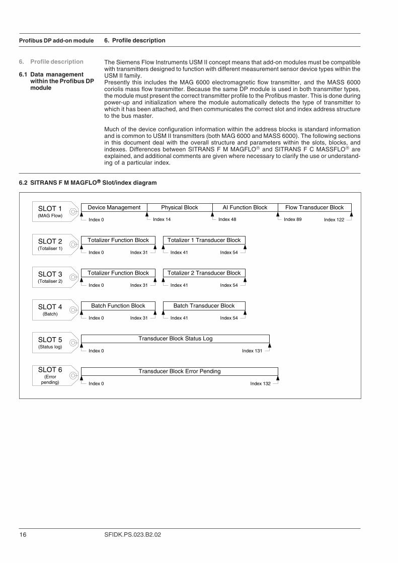
The Siemens Flow Instruments USM II concept means that add-on modules must be compatiblewith transmitters designed to function with different measurement sensor device types within theUSM II family.Presently this includes the MAG 6000 electromagnetic flow transmitter, and the MASS 6000coriolis mass flow transmitter. Because the same DP module is used in both transmitter types,the module must present the correct transmitter profile to the Profibus master. This is done duringpower-up and initialization where the module automatically detects the type of transmitter towhich it has been attached, and then communicates the correct slot and index address structureto the bus master.
Much of the device configuration information within the address blocks is standard informationand is common to USM II transmitters (both MAG 6000 and MASS 6000). The following sectionsin this document deal with the overall structure and parameters within the slots, blocks, andindexes. Differences between SITRANS F M MAGFLO® and SITRANS F C MASSFLO® areexplained, and additional comments are given where necessary to clarify the use or understand-ing of a particular index.
6.2 SITRANS F M MAGFLO®®®®® Slot/index diagram
Device Management Physical Block AI Function Block Flow Transducer Block
Totalizer Function Block Totalizer 1 Transducer Block
Batch Function Block Batch Transducer Block
Transducer Block Status Log
Transducer Block Error Pending
Totalizer Function Block Totalizer 2 Transducer Block
Index 14Index 0 Index 48 Index 89 Index 122
Index 0
Index 0
Index 0
Index 0
Index 0
Index 31
Index 31
Index 31
Index 41
Index 41
Index 41
Index 54
Index 54
Index 54
Index 131
Index 132
SLOT 1(MAG Flow)
SLOT 2(Totaliser 1)
SLOT 3(Totaliser 2)
SLOT 4(Batch)
SLOT 5(Status log)
SLOT 6(Error
pending)
Profibus DP add-on module
17SFIDK.PS.023.B2.02
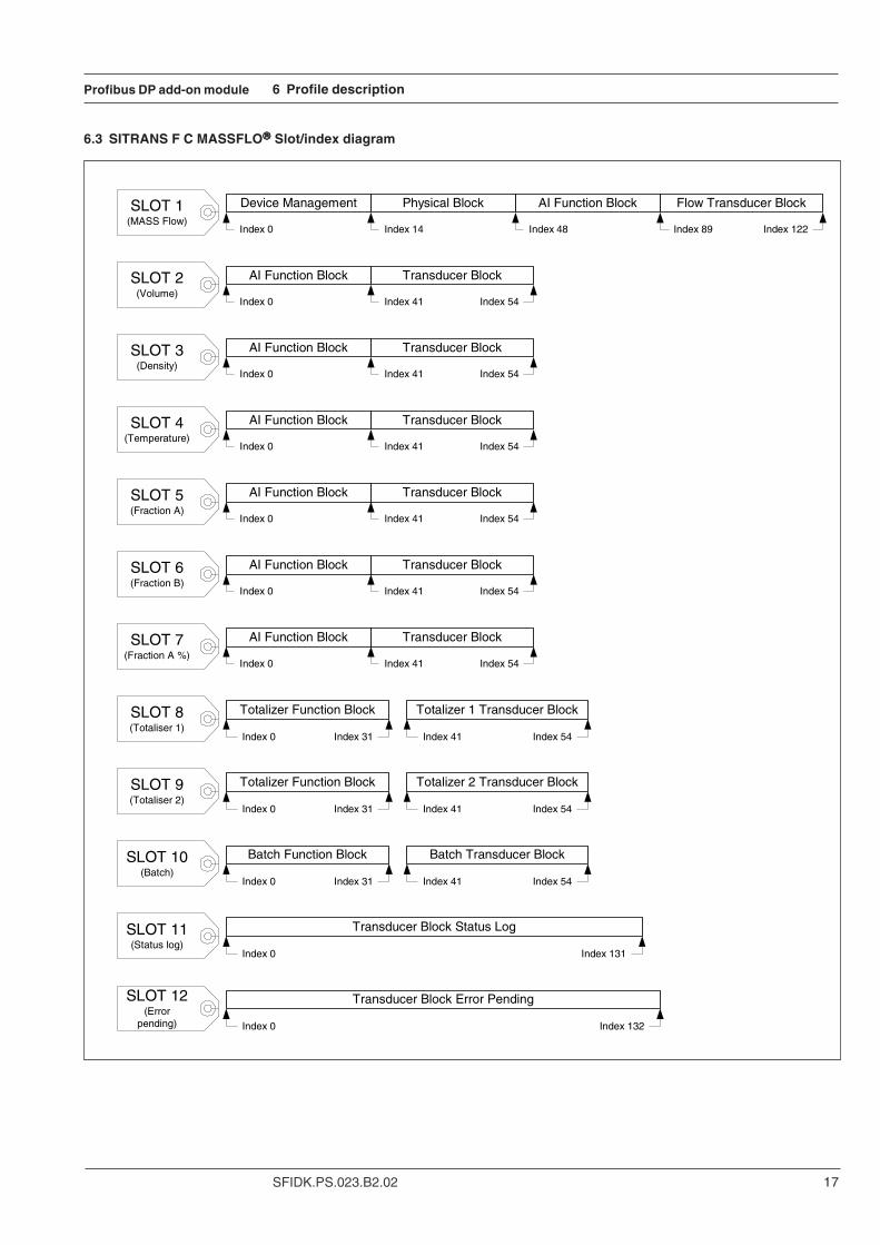
6.3 SITRANS F C MASSFLO®®®®® Slot/index diagram
6 Profile description
Device Management Physical Block AI Function Block Flow Transducer Block
Totalizer Function Block Totalizer 1 Transducer Block
Batch Function Block Batch Transducer Block
Transducer Block Status Log
Transducer Block Error Pending
Totalizer Function Block Totalizer 2 Transducer Block
AI Function Block Transducer Block
AI Function Block Transducer Block
AI Function Block Transducer Block
AI Function Block Transducer Block
AI Function Block Transducer Block
AI Function Block Transducer Block
Index 14Index 0 Index 48 Index 89 Index 122
Index 0
Index 0
Index 0
Index 0
Index 0 Index 41
Index 41
Index 41
Index 41
Index 41
Index 41Index 0
Index 54
Index 54
Index 54
Index 54
Index 54
Index 54
Index 0
Index 0
Index 0
Index 0
Index 0
Index 31
Index 31
Index 31
Index 41
Index 41
Index 41
Index 54
Index 54
Index 54
Index 131
Index 132
SLOT 1(MASS Flow)
SLOT 2(Volume)
SLOT 3(Density)
SLOT 4(Temperature)
SLOT 5(Fraction A)
SLOT 6(Fraction B)
SLOT 8(Totaliser 1)
SLOT 9(Totaliser 2)
SLOT 10(Batch)
SLOT 11(Status log)
SLOT 12(Error
pending)
SLOT 7(Fraction A %)
18 SFIDK.PS.023.B2.02
Profibus DP add-on module
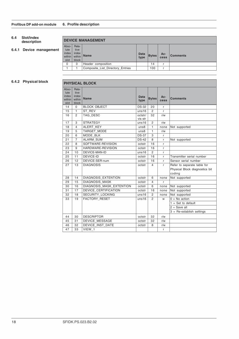
6.4 Slot/indexdescription
6.4.1 Device managementData Bytes Ac-Name type cess Comments
0 0 Header composition 14 r1 1 Composite_List_Directory_Entries 100 r
DEVICE MANAGEMENT
Abso-lute
indexwithinslot
Rela-tive
indexwithinblock
6. Profile description
Data Bytes Ac-Name type cess Comments
14 0 BLOCK OBJECT DS-32 20 r15 1 ST_REV uns16 2 r16 2 TAG_DESC octstr/ 32 r/w
vis str17 3 STRATEGY uns16 2 r/w 18 4 ALERT_KEY uns8 1 none Not supported19 5 TARGET_MODE uns8 1 r/w20 6 MODE_BLK DS-37 3 r21 7 ALARM_SUM DS-42 8 r Not supported22 8 SOFTWARE-REVISION octstr 16 r23 9 HARDWARE-REVISION octstr 16 r24 10 DEVICE-MAN-ID uns16 2 r25 11 DEVICE-ID octstr 16 r Transmitter serial number26 12 DEVICE-SER-num octstr 16 r Sensor serial number27 13 DIAGNOSIS octstr 4 r Refer to separate table for
Physical Block diagnostics bitcoding
28 14 DIAGNOSIS_EXTENTION octstr 6 none Not supported29 15 DIAGNOSIS_MASK octstr 4 r30 16 DIAGNOSIS_MASK_EXTENTION octstr 6 none Not supported31 17 DEVICE_CERTIFICATION octstr 16 none Not supported32 18 SECURITY_LOCKING uns16 2 none Not supported33 19 FACTORY_RESET uns16 2 w 0 = No action
1 = Set to default2 = Save all3 = Re-establish settings
44 30 DESCRIPTOR octstr 32 r/w45 31 DEVICE_MESSAGE octstr 32 r/w46 32 DEVICE_INST_DATE octstr 8 r/w47 33 VIEW_1 r
PHYSICAL BLOCK
Abso-lute
indexwithinslot
Rela-tive
indexwithinblock
6.4.2 Physical block
Profibus DP add-on module
19SFIDK.PS.023.B2.02
Data Bytes Ac-Name type cess Comments
48 0 BLOCK OBJECT DS-32 20 r49 1 ST_REV uns16 2 r50 2 TAG_DESC octstr/
vis str 32 r/w51 3 STRATEGY uns16 2 r/w52 4 ALERT_KEY uns8 1 none53 5 TARGET_MODE uns8 1 r/w54 6 MODE_BLK DS-37 3 r Default = AUTO55 7 ALARM_SUM (not implemented) DS-42 8 r58 10 OUT DS-33 5 r Measured variable with status.
This value is the same as thecyclic value.
59 11 PV_SCALE DS-36 11 r/w60 12 OUT_SCALE DS-36 11 r/w62 14 CHANNEL uns16 2 r/w64 16 PV_FTIME float 4 r/w Filter time in sec.67 19 ALARM_HYS float 4 r/w Hysteresis in eng. units of LIM69 21 HI_HI_LIM float 4 r/w71 23 HI_LIM float 4 r/w73 25 LO_LIM float 4 r/w75 27 LO_LO_LIM float 4 r/w78 30 HI_HI_ALM DS-39 16 r79 31 HI_ALM DS-39 16 r80 32 LO_ALM DS-39 16 r81 33 LO_LO_ALM DS-39 16 r82 34 SIMULATE DS-50 6 r/w
83-87 35-39 Reserved by PNO88 40 VIEW_1 r
ANALOG INPUT FUNCTION BLOCK (SLOT 1)
Abso-lute
indexwithinslot
Rela-tive
indexwithinblock
6. Profile description
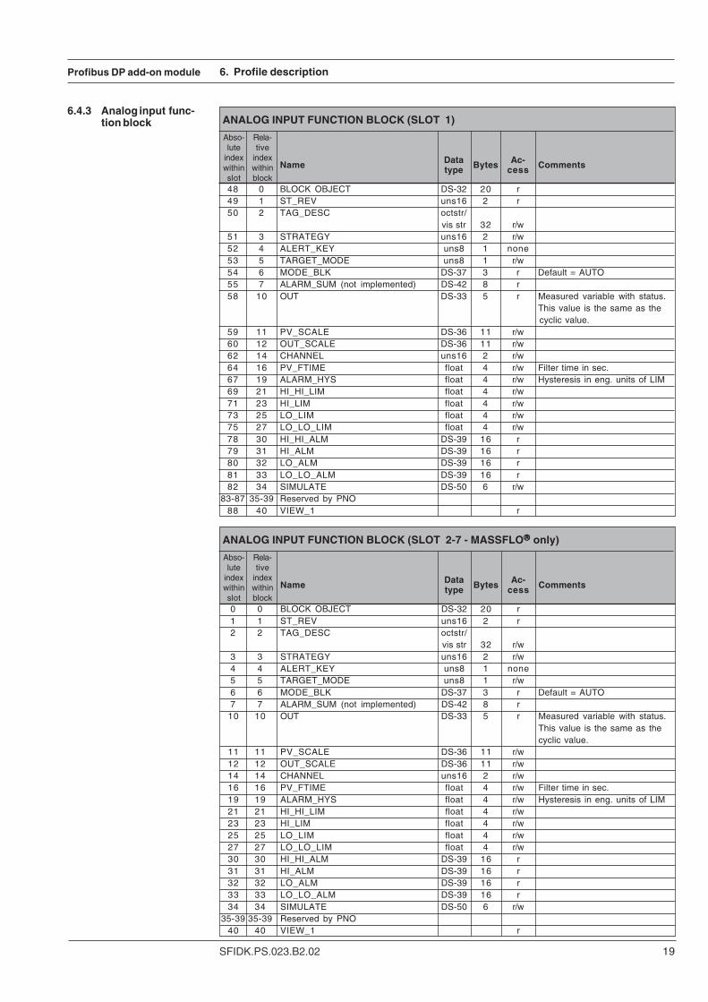
6.4.3 Analog input func-tion block
Data Bytes Ac-Name type cess Comments
0 0 BLOCK OBJECT DS-32 20 r1 1 ST_REV uns16 2 r2 2 TAG_DESC octstr/
vis str 32 r/w3 3 STRATEGY uns16 2 r/w4 4 ALERT_KEY uns8 1 none5 5 TARGET_MODE uns8 1 r/w6 6 MODE_BLK DS-37 3 r Default = AUTO7 7 ALARM_SUM (not implemented) DS-42 8 r
10 10 OUT DS-33 5 r Measured variable with status.This value is the same as thecyclic value.
11 11 PV_SCALE DS-36 11 r/w12 12 OUT_SCALE DS-36 11 r/w14 14 CHANNEL uns16 2 r/w16 16 PV_FTIME float 4 r/w Filter time in sec.19 19 ALARM_HYS float 4 r/w Hysteresis in eng. units of LIM21 21 HI_HI_LIM float 4 r/w23 23 HI_LIM float 4 r/w25 25 LO_LIM float 4 r/w27 27 LO_LO_LIM float 4 r/w30 30 HI_HI_ALM DS-39 16 r31 31 HI_ALM DS-39 16 r32 32 LO_ALM DS-39 16 r33 33 LO_LO_ALM DS-39 16 r34 34 SIMULATE DS-50 6 r/w
35-39 35-39 Reserved by PNO40 40 VIEW_1 r
ANALOG INPUT FUNCTION BLOCK (SLOT 2-7 - MASSFLO®®®®® only)
Abso-lute
indexwithinslot
Rela-tive
indexwithinblock

20 SFIDK.PS.023.B2.02
Profibus DP add-on module
DataBytes
Ac-Name type cess Comments
89 0 BLOCK OBJECT DS-32 20 r 90 1 ST_REV uns16 2 r 91 2 TAG_DESC octstr/ 32 r/w
vis str92 3 STRATEGY uns16 2 r/w 93 4 ALERT_KEY uns8 1 none 94 5 TARGET_MODE uns8 1 r/w 95 6 MODE_BLK DS-37 3 r 96 7 ALARM_SUM (not implemented) DS-42 8 r 97 8 FLOWRATE float 4 r MAG = Volume flow
MASS = Mass flow98 9 NOMINAL_SIZE float 4 r/w Access is determined by
SENSORPROM®
99 10 FILTER_TYPE (not implemented) uns8 1 none 100 11 DEVICE_MODE uns8 1 r/w Always bi-directional 101 12 FLOWRATE_UNITS uns16 2 r/w 102 13 SELF_CHECKING uns8 1 none Not applicable103 14 CALIBRATION_FACTOR float 4 r/w Access determined by
SENSORPROM®
104 15 ZERO_POINT float 4 r/w MAG = Sensor offsetMASS = Zero offset
105 16 FLOW_DIRECTION uns8 1 r/w106 17 UPPER_SENSOR_LIMIT float 4 r MAG = Scale upper
MASS = Mass flow scale upper107 18 LOWER_SENSOR_LIMIT float 4 r MAG = Scale upper
MASS = Mass flow scale upper108 19 SAMPLE_RATE float 4 r MAG = Flow rate broadcast
intervalMASS = Mass flow rate broad-cast interval
109 20 EPD_THRESHOLD float 4 r/w MAG = Not supportedMASS = Empty pipe limit
110 21 LOW FLOW CUTOFF*) float 4 r/w PROFIBUS values only. Notassociated with low flow cut offin the flowmeter.See description below.
111 22 MASS_FLOWRATE float 4 r MASS only112 23 MASS_FLOWRATE_UNIT uns16 2 r MASS only113 24 ZERO_POINT_ADJUST uns8 1 r/w MASS only114 25 OSCILLATION_FREQ: float 4 r MAG = Not applicable
MASS = Sensor frequency115 26 VORTEX_FREQ float 4 none Not applicable 116 27 VOLUME_FLOW float 4 r MASS only117 28 VOLUME_FLOW_UNITS uns16 2 r/w MASS only118 29 TEMPERATURE float 4 r MASS only119 30 TEMPERATURE_UNITS uns16 2 r/w MASS only120 31 DENSITY float 4 r MASS only121 32 DENSITY_UNITS uns16 2 r/w MASS only122 33 VIEW_1 r
*) See next page
FLOW TRANSDUCER BLOCK (SLOT 1)
Abso-lute
indexwithinslot
Rela-tive
indexwithinblock
6. Profile description
6.4.4 Flow transducerblock
Profibus DP add-on module
21SFIDK.PS.023.B2.02
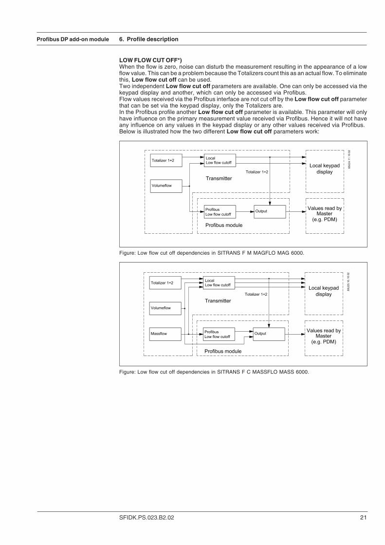
LOW FLOW CUT OFF*)When the flow is zero, noise can disturb the measurement resulting in the appearance of a lowflow value. This can be a problem because the Totalizers count this as an actual flow. To eliminatethis, Low flow cut off can be used.Two independent Low flow cut off parameters are available. One can only be accessed via thekeypad display and another, which can only be accessed via Profibus.Flow values received via the Profibus interface are not cut off by the Low flow cut off parameterthat can be set via the keypad display, only the Totalizers are.In the Profibus profile another Low flow cut off parameter is available. This parameter will onlyhave influence on the primary measurement value received via Profibus. Hence it will not haveany influence on any values in the keypad display or any other values received via Profibus.Below is illustrated how the two different Low flow cut off parameters work:
6. Profile description
Figure: Low flow cut off dependencies in SITRANS F M MAGFLO MAG 6000.
Figure: Low flow cut off dependencies in SITRANS F C MASSFLO MASS 6000.
22 SFIDK.PS.023.B2.02
Profibus DP add-on module
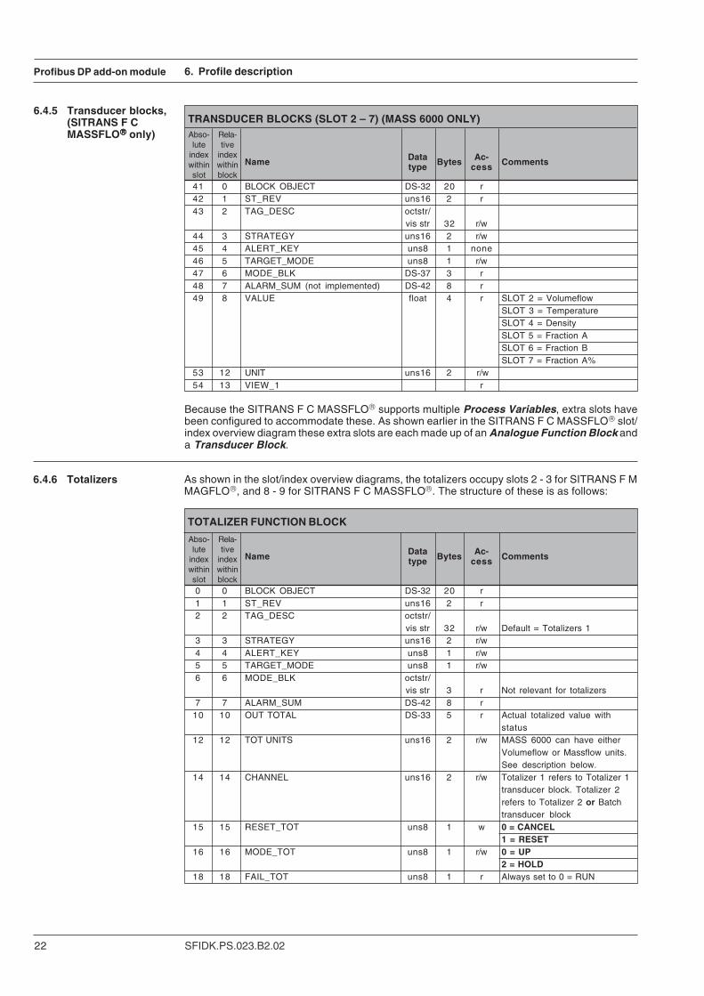
TRANSDUCER BLOCKS (SLOT 2 – 7) (MASS 6000 ONLY)
6. Profile description
Data Bytes Ac-Name type cess Comments
41 0 BLOCK OBJECT DS-32 20 r42 1 ST_REV uns16 2 r43 2 TAG_DESC octstr/
vis str 32 r/w44 3 STRATEGY uns16 2 r/w45 4 ALERT_KEY uns8 1 none46 5 TARGET_MODE uns8 1 r/w47 6 MODE_BLK DS-37 3 r48 7 ALARM_SUM (not implemented) DS-42 8 r49 8 VALUE float 4 r SLOT 2 = Volumeflow
SLOT 3 = TemperatureSLOT 4 = DensitySLOT 5 = Fraction ASLOT 6 = Fraction BSLOT 7 = Fraction A%
53 12 UNIT uns16 2 r/w54 13 VIEW_1 r
Abso-lute
indexwithinslot
Rela-tive
indexwithinblock
Because the SITRANS F C MASSFLO® supports multiple Process Variables, extra slots havebeen configured to accommodate these. As shown earlier in the SITRANS F C MASSFLO® slot/index overview diagram these extra slots are each made up of an Analogue Function Block anda Transducer Block.
6.4.5 Transducer blocks,(SITRANS F CMASSFLO®®®®® only)
Data Bytes Ac-Name type cess Comments
0 0 BLOCK OBJECT DS-32 20 r1 1 ST_REV uns16 2 r2 2 TAG_DESC octstr/
vis str 32 r/w Default = Totalizers 13 3 STRATEGY uns16 2 r/w4 4 ALERT_KEY uns8 1 r/w5 5 TARGET_MODE uns8 1 r/w6 6 MODE_BLK octstr/
vis str 3 r Not relevant for totalizers7 7 ALARM_SUM DS-42 8 r
10 10 OUT TOTAL DS-33 5 r Actual totalized value withstatus
12 12 TOT UNITS uns16 2 r/w MASS 6000 can have eitherVolumeflow or Massflow units.See description below.
14 14 CHANNEL uns16 2 r/w Totalizer 1 refers to Totalizer 1transducer block. Totalizer 2refers to Totalizer 2 or Batchtransducer block
15 15 RESET_TOT uns8 1 w 0 = CANCEL1 = RESET
16 16 MODE_TOT uns8 1 r/w 0 = UP2 = HOLD
18 18 FAIL_TOT uns8 1 r Always set to 0 = RUN
TOTALIZER FUNCTION BLOCK
Abso-lute
indexwithinslot
Rela-tive
indexwithinblock
6.4.6 Totalizers As shown in the slot/index overview diagrams, the totalizers occupy slots 2 - 3 for SITRANS F MMAGFLO®, and 8 - 9 for SITRANS F C MASSFLO®. The structure of these is as follows:
Profibus DP add-on module
23SFIDK.PS.023.B2.02
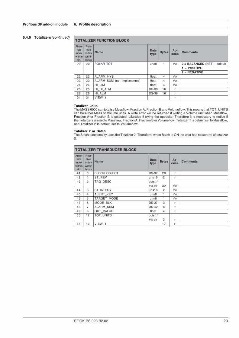
Data Bytes Ac-Name type cess Comments
20 20 POLAR TOT uns8 1 r/w 0 = BALANCED (NET) - default1 = POSITIVE2 = NEGATIVE
22 22 ALARM_HYS float 4 r/w23 23 ALARM_SUM (not implemented) float 4 r/w24 24 HI_LIM float 4 r/w25 25 HI_HI_ALM DS-39 16 r26 26 HI_ALM DS-39 16 r31 31 VIEW_1 r
TOTALIZER FUNCTION BLOCK
Abso-lute
indexwithinslot
Rela-tive
indexwithinblock
6.4.6 Totalizers (continued)
6. Profile description
Data Bytes Ac-Name type cess Comments
41 0 BLOCK OBJECT DS-32 20 r42 1 ST_REV uns16 2 r43 2 TAG_DESC octstr/
vis str 32 r/w44 3 STRATEGY uns16 2 r/w45 4 ALERT_KEY uns8 1 r/w46 5 TARGET_MODE uns8 1 r/w47 6 MODE_BLK DS-37 3 r48 7 ALARM_SUM DS-42 8 r49 8 OUT_VALUE float 4 r53 12 TOT_UNITS octstr/
vis str 2 r54 13 VIEW_1 17 r
TOTALIZER TRANSDUCER BLOCK
Abso-lute
indexwithinslot
Rela-tive
indexwithinblock
Totalizer unitsThe MASS 6000 can totalise Massflow, Fraction A, Fraction B and Volumeflow. This means that TOT_UNITScan be either Mass or Volume units. A write error will be returned if writing a Volume unit when Massflow,Fraction A or Fraction B is selected. Likewise if trying the opposite. Therefore it is necessary to notice ifthe Totalizers are set to Massflow, Fraction A, Fraction B or Volumeflow. Totalizer 1 is default set to Massflow,and Totalizer 2 is default set to Volumeflow.
Totalizer 2 or BatchThe Batch functionality uses the Totalizer 2. Therefore, when Batch is ON the user has no control of totalizer2.

24 SFIDK.PS.023.B2.02
Profibus DP add-on module
Data Bytes Ac-Name type cess Comments
0 0 BLOCK OBJECT DS-32 20 r1 1 ST_REV Uns16 2 r2 2 TAG_DESC octstr/
vis str 32 r/w3 3 STRATEGY Uns16 2 r/w4 4 ALERT_KEY (not supported) Uns8 1 r/w5 5 TARGET_MODE Uns8 1 r/w6 6 MODE_BLK octstr/
vis str 3 r7 7 ALARM_SUM DS-42 8 r
10 10 AMOUNT_DONE DS-33 5 r Batch total amount12 12 BATCH_UNITS Uns16 2 r/w Units for batch14 14 CHANNEL Uns16 2 r/w15 15 CYCLE CNT RESET Uns8 1 w 0 = CANCEL
1 = RESET16 16 MODE BATCH Uns8 1 r/w 0 = UP (Not supported)
1 = DOWN (Not supported)2 = HOLD (Not supported)3 = BATCH (Not supported)4 = START5 = STOP6 = PAUSE7 = RESUME8 = OFF (Not selected)
18 18 FAIL BATCH Uns8 1 r Can only be 0 = RUN20 20 POLAR TOT Uns8 1 r Not applicable - not supported21 21 BATCH ON OFF Uns8 1 r/w22 22 ALARM_HYS float 4 r/w23 23 HI_HI_LIM float 4 r/w24 24 HI_LIM float 4 r/w25 25 HI_HI_ALM DS-39 16 r26 26 HI_ALM DS-39 16 r27 27 TIMEOUT Uns32 4 r/w28 28 CYCLE COUNTER Uns32 4 r29 29 COMPENSATION float 4 r/w30 30 SETPOINT float 4 r/w31 31 VIEW_1 r
BATCH FUNCTION BLOCK
Abso-lute
indexwithinslot
Rela-tive
indexwithinblock
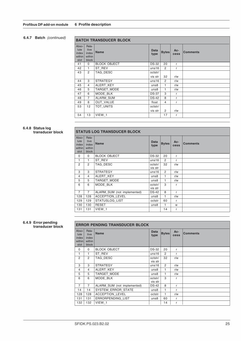
6.4.7 Batch As shown in the slot/index overview diagrams, the batch function occupies slot 4 for SITRANSF M MAGFLO®, and 10 for SITRANS F C MASSFLO®. The Batch Function Block is based onthe Totalizer Function Block and shares almost identical structure. The totalizer 2 and the BatchFunction Blocks are exclusive, only one of these can exist at a time in the USM II Profibus module.If the Batch functionality is activated, then Totalizer 2 is excluded and cannot be used fortotalizing. Totalizer 2 can be used if Batch is deactivated.
6. Profile description
Batch unitsThe MASS 6000 can Batch Massflow, Fraction A, Fraction B and Volumeflow. This means thatBATCH_UNITS can be either Mass or Volume units. A write error will be returned if writing aVolume unit when Massflow, Fraction A or Fraction B is selected. Likewise if trying to write a Massunit when Volumeflow is selected. Therefore it is necessary to notice if the Batch is set to Massflow,Fraction A, Fraction B or Volumeflow. Batch is default set to Massflow.
- this page has been updated 01-2005
Profibus DP add-on module
25SFIDK.PS.023.B2.02
Data Bytes Ac-Name type cess Comments
0 0 BLOCK OBJECT DS-32 20 r 1 1 ST_REV uns16 2 r 2 2 TAG_DESC octstr/ 32 r/w
vis str 3 3 STRATEGY uns16 2 r/w 4 4 ALERT_KEY uns8 1 r/w 5 5 TARGET_MODE uns8 1 r/w 6 6 MODE_BLK octstr/ 3 r
vis str 7 7 ALARM_SUM (not implemented) DS-42 8 r
128 128 ACCEPTION_LEVEL uns8 1 r/w 129 129 STATUSLOG_LIST octstr 60 r 130 130 RESET uns8 1 w 131 131 VIEW_1 14 r
STATUS LOG TRANSDUCER BLOCK
Abso-lute
indexwithinslot
Rela-tive
indexwithinblock
Data Bytes Ac-Name type cess Comments
0 0 BLOCK OBJECT DS-32 20 r1 1 ST_REV uns16 2 r2 2 TAG_DESC octstr/ 32 r/w
vis str3 3 STRATEGY uns16 2 r/w4 4 ALERT_KEY uns8 1 r/w5 5 TARGET_MODE uns8 1 r/w6 6 MODE_BLK octstr/ 3 r
vis str7 7 ALARM_SUM (not implemented) DS-42 8 r
14 14 SYSTEM_ERROR_STATE uns8 1 r128 128 ACCEPTION_LEVEL octstr 1 r/w131 131 ERRORPENDING_LIST uns8 60 r132 132 VIEW_1 14 r
ERROR PENDING TRANSDUCER BLOCK
Abso-lute
indexwithinslot
Rela-tive
indexwithinblock
6 Profile description
6.4.8 Status logtransducer block
6.4.9 Error pendingtransducer block
Data Bytes Ac-Name type cess Comments
41 0 BLOCK OBJECT DS-32 20 r42 1 ST_REV uns16 2 r43 2 TAG_DESC octstr/
vis str 32 r/w44 3 STRATEGY uns16 2 r/w45 4 ALERT_KEY uns8 1 r/w46 5 TARGET_MODE uns8 1 r/w47 6 MODE_BLK DS-37 3 r48 7 ALARM_SUM DS-42 8 r49 8 OUT_VALUE float 4 r53 12 TOT_UNITS octstr/
vis str 2 r/w54 13 VIEW_1 17 r
BATCH TRANSDUCER BLOCK
Abso-lute
indexwithinslot
Rela-tive
indexwithinblock
6.4.7 Batch (continued)
26 SFIDK.PS.023.B2.02
Profibus DP add-on module
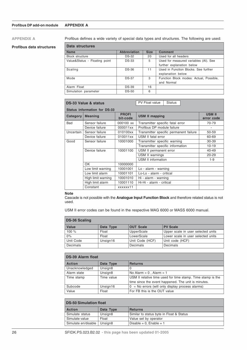
Name Abbreviation Size CommentBlock structure DS-32 20 Used for all headersValue&Status - Floating point DS-33 5 Used for measured variables (AI). See
further explanation belowScaling DS-36 11 Used in Function Blocks. See further
explanation belowMode DS-37 3 Function Block modes: Actual, Possible,
and NormalAlarm Float DS-39 16Simulation parameter DS-50 6
Data structures
APPENDIX A
APPENDIX A
Profibus data structures
Profibus defines a wide variety of special data types and structures. The following are used:
DS-33 Value & status
Status information for DS-33
Category Meaning PROFI USM II mapping USM IIbit-code error code
Bad Sensor failure 000100 xx Transmitter specific fatal error 70-79Device failure 000011xx Profibus DP module failure -
Uncertain Sensor failure 010100xx Transmitter specific permanent failure 50-59Device failure 010011xx USM II fatal error 60-69
Good Sensor failure 10001000 Transmitter specific warning 30-39Transmitter specific information 10-19
Device failure 10001100 USM II permanent error 40-49USM II warnings 20-29USM II information 1-9
OK 10000000Low limit warning 10001001 Lo - alarm - warningLow limit alarm 10001101 Lo-Lo - alarm - criticalHigh limit warning 10001010 Hi - alarm - warningHigh limit alarm 10001110 Hi-Hi - alarm - criticalConstant xxxxxx11
PV Float value Status
DS-36 Scaling
Value Data Type OUT Scale PV Scale100 % Float UpperScale Upper scale in user selected units0% Float LowerScale Lower scale in user selected unitsUnit Code Unsign16 Unit Code (HCF) Unit code (HCF)Decimals Decimals Decimals
DS-39 Alarm float
Action Data Type ReturnsUnacknowledged Unsign8 0Alarm state Unsign8 No Alarm = 0 , Alarm = 1Time stamp Time value USM II relative time used for time stamp. Time stamp is the
time since the event happened. The unit is minutes.Subcode Unsign16 0 = No errors (will only display process alarms)Value Float For FB this is the OUT value
DS-50 Simulation float
Action Data Type ReturnsSimulate status Unsign8 Similar to status byte in Float & StatusSimulate value Float Value set by operatorSimulate en/disable Unsign8 Disable = 0, Enable = 1
NoteCascade is not possible with the Analogue Input Function Block and therefore related status is notused.
USM II error codes can be found in the respective MAG 6000 or MASS 6000 manual.
- this page has been updated 01-2005
Profibus DP add-on module
27SFIDK.PS.023.B2.02
APPENDIX B & C
APPENDIX B
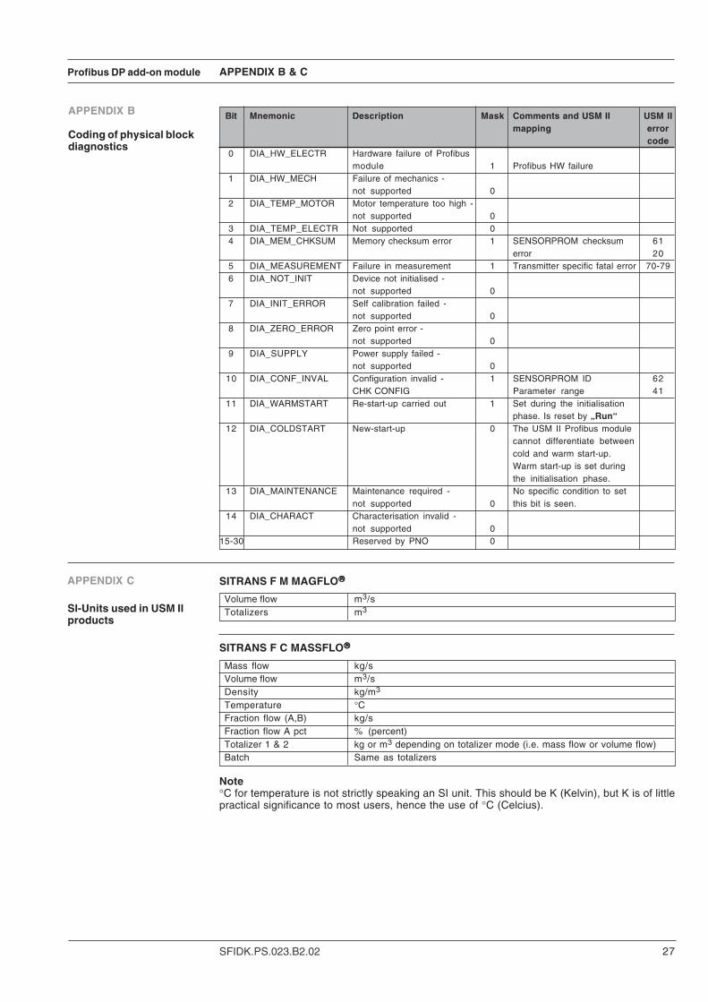
Coding of physical blockdiagnostics
Bit Mnemonic Description Mask Comments and USM II USM IImapping error
code0 DIA_HW_ELECTR Hardware failure of Profibus
module 1 Profibus HW failure1 DIA_HW_MECH Failure of mechanics -
not supported 02 DIA_TEMP_MOTOR Motor temperature too high -
not supported 03 DIA_TEMP_ELECTR Not supported 04 DIA_MEM_CHKSUM Memory checksum error 1 SENSORPROM checksum 61
error 205 DIA_MEASUREMENT Failure in measurement 1 Transmitter specific fatal error 70-796 DIA_NOT_INIT Device not initialised -
not supported 07 DIA_INIT_ERROR Self calibration failed -
not supported 08 DIA_ZERO_ERROR Zero point error -
not supported 09 DIA_SUPPLY Power supply failed -
not supported 010 DIA_CONF_INVAL Configuration invalid - 1 SENSORPROM ID 62
CHK CONFIG Parameter range 4111 DIA_WARMSTART Re-start-up carried out 1 Set during the initialisation
phase. Is reset by „Run“12 DIA_COLDSTART New-start-up 0 The USM II Profibus module
cannot differentiate betweencold and warm start-up.Warm start-up is set duringthe initialisation phase.
13 DIA_MAINTENANCE Maintenance required - No specific condition to setnot supported 0 this bit is seen.
14 DIA_CHARACT Characterisation invalid -not supported 0
15-30 Reserved by PNO 0
APPENDIX C
SI-Units used in USM IIproducts
SITRANS F M MAGFLO®®®®®
Volume flow m3/sTotalizers m3
SITRANS F C MASSFLO®®®®®
Mass flow kg/sVolume flow m3/sDensity kg/m3
Temperature °CFraction flow (A,B) kg/sFraction flow A pct % (percent)Totalizer 1 & 2 kg or m3 depending on totalizer mode (i.e. mass flow or volume flow)Batch Same as totalizers
Note°C for temperature is not strictly speaking an SI unit. This should be K (Kelvin), but K is of littlepractical significance to most users, hence the use of °C (Celcius).
28 SFIDK.PS.023.B2.02
Profibus DP add-on module APPENDIX D
APPENDIX D
Batching with Profibus
The flowmeter includes a Batch controller. This means that it can control a valve or similar fromthe digital output. The Batch can be started in many ways; from the local display, via the digitalinput or from Profibus.The following will describe Batch control from Profibus.
Steps to take when batching:
• Set up amount to be batched• Start batch• Poll for status• When (status = stopped), prepare a new batch
The actual amount batched can differ from the set-point due to delays in valves, pressurizingflexible pipes etc. Therefore a fixed compensation can be set up using the „Compensation“parameter:
• Make one batch (precision increases if an average is calculated from several batches)• Find the deviation• Write the deviation to the „Compensation“ parameter
From Profibus the control can be done either cyclic (DPV0) or acyclic (DPV1). A Class 1 ProfibusMasters can use the cyclic control, whereas a Class 2 Master like Simatic PDM can access theacyclic control.The acyclic control is straight forward to use, whereas the cyclic control needs some moreexplanation.

Profibus DP add-on module
29SFIDK.PS.023.B2.02
APPENDIX D
Cyclic Batch control Three modules can be configured for the use of Batch; Batch Control, Batch Set-point and BatchCompensation. The Batch Control module is mandatory, and Batch Set-point and Compen-sation are optional. This means that Batch Set-point and/or Compensation cannot be configuredwithout also configuring Batch Control.The modules are described in the chapter: Output data (Master view).Below is described the required steps to take when Batching.
Batch ON/OFF mask (BOFM)This bit masks the Batch ON/OFF (BOF). If BOFM is „0“ then the state of BOF is ignored. WhenBOFM is „1“ the state of BOF is detected and acted upon.
Batch ON/OFF (BOF)To be able to Batch the Batch function must be set active. To set Batch active, set BOF = „1“, andset BOFM „1“ for minimum 100 mS and then back to „0“. Now BOF can be set back to „0“, and Batchis active. To deactivate Batch, set BOFM to „1“ (condition: BOF = „0“) for minimum 100 mS andthen back to „0“.Setting Batch = ON will change the behavior of Totalizer 2. Totalizer 2 will now show the progressof the Batch. Making a Batch start will set Totalizer 2 = Set-point, and Totalizer 2 will count downto zero.
Update Set-point and Compensation (USC)On the positive edge from „0“ to „1“ this bit updates the values of Set-point and Compensationin the flowmeter.
30 SFIDK.PS.023.B2.02
Profibus DP add-on module APPENDIX D
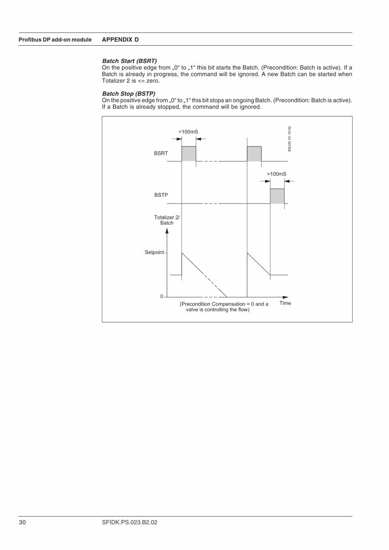
Batch Start (BSRT)On the positive edge from „0“ to „1“ this bit starts the Batch. (Precondition: Batch is active). If aBatch is already in progress, the command will be ignored. A new Batch can be started whenTotalizer 2 is <= zero.
Batch Stop (BSTP)On the positive edge from „0“ to „1“ this bit stops an ongoing Batch. (Precondition: Batch is active).If a Batch is already stopped, the command will be ignored.

Profibus DP add-on module
31SFIDK.PS.023.B2.02

We have checked the contents of this manual for agreement with the hardware andsoftware described. Since deviations cannot be precluded entirely, we cannot guaranteefull agreement. However, the data in this manual are reviewed regularly and anynecessary corrections included in subsequent editions. Suggestions for improvementare always welcomed.
Technical data subject to change without prior notice.
The reproduction, transmission or use of this document or its contents is not permitted withoutexpress written authority.Offenders will be liable for damages. All rights, including rights created by patent grant orregistration of a utility model or design, are reserved.
Copyright © Siemens AG 01-2004 All Rights Reserved
Siemens Flow Instruments A/SNordborgvej 81DK-6430 Nordborg
Order no.: FDK:521H1185-02Printed in: Denmark