siw slot antenna for e-band communications · siw slot antenna for e-band communications dmitry...
TRANSCRIPT

SIW slot antenna for E-band communications
Zelenchuk, D., Fusco, V., Breslin, J., & Keaveney, M. (2015). SIW slot antenna for E-band communications. InProceedings of the 45th European Microwave Conference (pp. 582-585). Institute of Electrical and ElectronicsEngineers (IEEE). DOI: 10.1109/EuMC.2015.7345830
Published in:Proceedings of the 45th European Microwave Conference
Document Version:Peer reviewed version
Queen's University Belfast - Research Portal:Link to publication record in Queen's University Belfast Research Portal
Publisher rights© 2015 IEEE. Personal use of this material is permitted. Permission from IEEE must be obtained for all other uses, in any current or futuremedia, includingreprinting/republishing this material for advertising or promotional purposes, creating new collective works, for resale or redistribution toservers or lists, or reuse of any copyrighted component of this work in other works.
General rightsCopyright for the publications made accessible via the Queen's University Belfast Research Portal is retained by the author(s) and / or othercopyright owners and it is a condition of accessing these publications that users recognise and abide by the legal requirements associatedwith these rights.
Take down policyThe Research Portal is Queen's institutional repository that provides access to Queen's research output. Every effort has been made toensure that content in the Research Portal does not infringe any person's rights, or applicable UK laws. If you discover content in theResearch Portal that you believe breaches copyright or violates any law, please contact [email protected].
Download date:02. Jul. 2018
SIW slot antenna for E-band communications
Dmitry Zelenchuk, Vincent Fusco
ECIT, Queen's University Belfast,
Belfast, United Kingdom
[email protected], [email protected]
James Breslin, Mike Keaveney
Analog Devices Inc.,
Limerick, Ireland
Abstract—The paper proposes novel substrate integrated
waveguide (SIW) slot antenna for E-band communications. The
antenna is designed at a two-layer low temperature co-fired
ceramic (LTCC) substrate in 71-76 GHz frequency band. The
proposed antenna demonstrates a gain better than 11.3 dBi and
efficiency of 85% and can be used as a standalone antenna or as
an element of a larger array.
Keywords—SIW, LTCC; slot antenna, E-band communications
I. INTRODUCTION
The large spectrum available has recently attracted attention to E-band backhaul systems [1]. Both 71-76 GHz and 81-86 GHz band allow 10 GHz of bandwidth for increased data rates in order to satisfy the demand on multi-gigabit wireless applications for mobile network infrastructure.
The wideband, high-gain antennas are required for these millimeter-wave applications. Due to quite stringent requirements the antenna solutions developed include horn arrays [2], lenses [3], and reflector antennas [4]. Those are bulky and can hardly be employed for compact mobile terminals. Waveguide slot antenna arrays [5] have recently been shown to provide good alternative to the bulky 3D structures. Still the manufacturing process can be precluding them from mass-market.
An alternative to the hollow waveguide is present in SIW waveguide antennas that have been successfully applied at mm-wave frequencies [6]. The SIW slot arrays with multilayer corporate feed have been demonstrating wideband and high-gain performance. However, the use of subsequent interlayer slot couplers can lead to a complicated design and increases cost. In this paper, we propose a dielectric loaded SIW slot antenna that employs only two dielectric layers and designed on LTCC substrate. The antenna can be subsequently used as an antenna element in larger arrays or as a standalone component.
II. DESIGN
A. Antenna description
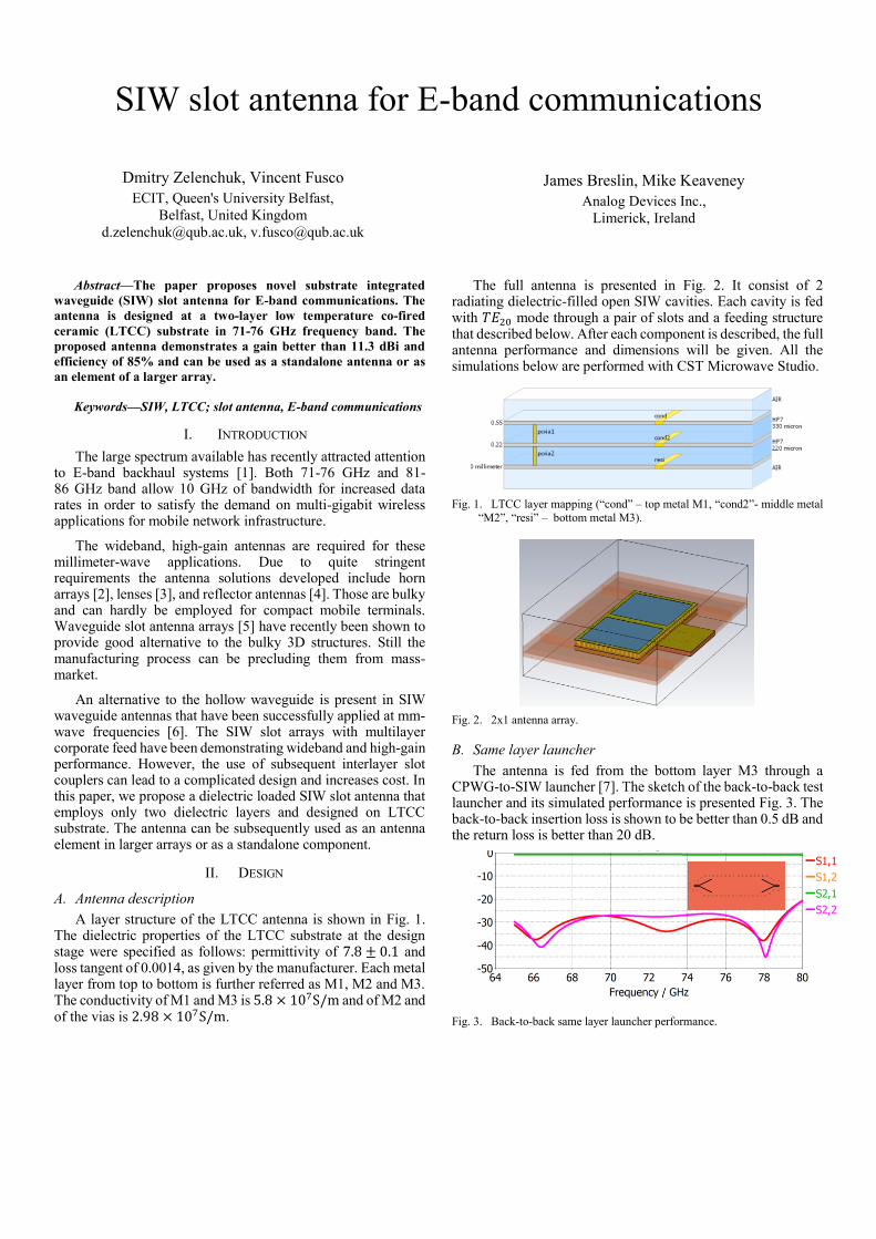
A layer structure of the LTCC antenna is shown in Fig. 1. The dielectric properties of the LTCC substrate at the design stage were specified as follows: permittivity of 7.8 ± 0.1 and loss tangent of 0.0014, as given by the manufacturer. Each metal layer from top to bottom is further referred as M1, M2 and M3. The conductivity of M1 and M3 is 5.8 × 10⁷S/m and of M2 and of the vias is 2.98 × 10⁷S/m.
The full antenna is presented in Fig. 2. It consist of 2 radiating dielectric-filled open SIW cavities. Each cavity is fed with 𝑇𝐸20 mode through a pair of slots and a feeding structure that described below. After each component is described, the full antenna performance and dimensions will be given. All the simulations below are performed with CST Microwave Studio.
Fig. 1. LTCC layer mapping (“cond” – top metal M1, “cond2”- middle metal
“M2”, “resi” – bottom metal M3).
Fig. 2. 2x1 antenna array.
B. Same layer launcher
The antenna is fed from the bottom layer M3 through a CPWG-to-SIW launcher [7]. The sketch of the back-to-back test launcher and its simulated performance is presented Fig. 3. The back-to-back insertion loss is shown to be better than 0.5 dB and the return loss is better than 20 dB.
Fig. 3. Back-to-back same layer launcher performance.
C. Equal power splitter and TE10-to-TE20 mode converter
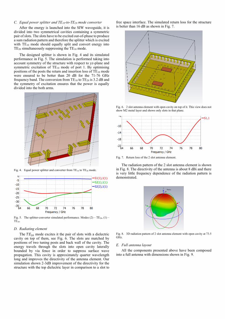
After the energy is launched into the SIW waveguide, it is divided into two symmetrical cavities containing a symmetric pair of slots. The slots have to be excited out-of-phase to produce a sum radiation pattern and therefore the splitter which is excited with TE10 mode should equally split and convert energy into TE20 simultaneously suppressing the TE10 mode.
The designed splitter is shown in Fig. 4 and its simulated performance in Fig. 5. The simulation is performed taking into account symmetry of the structure with respect to yz-plane and symmetric excitation of TE10 mode of port 1. By optimising positions of the posts the return and insertion loss of TE10 mode were ensured to be better than 20 dB for the 71-76 GHz frequency band. The conversion from TE10 to TE20 is 3.2 dB and the symmetry of excitation ensures that the power is equally divided into the both arms.
Fig. 4. Equal power splitter and converter from TE10 to TE20 mode.
Fig. 5. The splitter-converter simulated performance. Modes (2) – TE20, (1) –
TE10.
D. Radiating element
The 𝑇𝐸20 mode excites it the pair of slots with a dielectric cavity on top of them, see Fig. 6. The slots are matched by positions of two tuning posts and back wall of the cavity. The energy travels through the slots into open cavity laterally bounded by via fence in order to suppress surface wave propagation. This cavity is approximately quarter wavelength long and improves the directivity of the antenna element. Our simulation shown 2-3dB improvement of the directivity for the structure with the top dielectric layer in comparison to a slot to
free space interface. The simulated return loss for the structure is better than 16 dB as shown in Fig. 7.
Fig. 6. 2 slot antenna element with open cavity on top of it. This view does not
show M2 metal layer and shows only slots in that plane.
Fig. 7. Return loss of the 2 slot antenna element.
The radiation pattern of the 2 slot antenna element is shown in Fig. 8. The directivity of the antenna is about 8 dBi and there is very little frequency dependence of the radiation pattern is demonstrated.
Fig. 8. 3D radiation pattern of 2 slot antenna element with open cavity at 73.5
GHz.
E. Full antenna layout
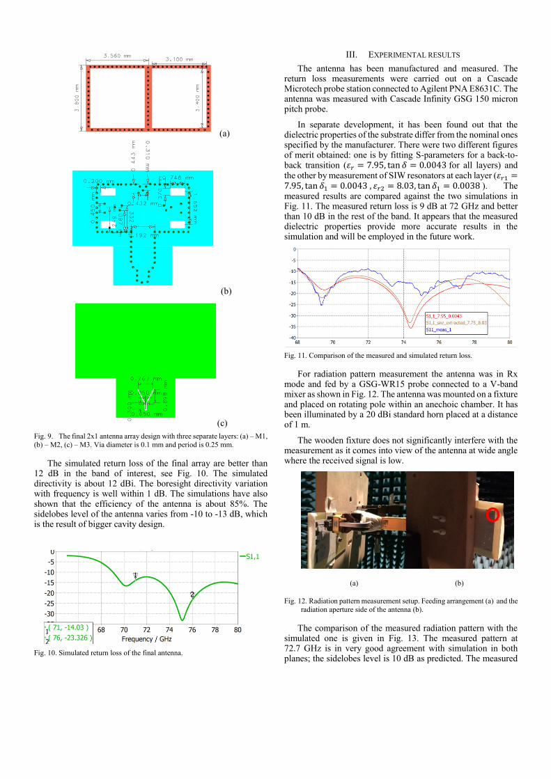
All the components presented above have been composed into a full antenna with dimensions shown in Fig. 9.
(a)
(b)
(c)
Fig. 9. The final 2x1 antenna array design with three separate layers: (a) – M1,
(b) – M2, (c) – M3. Via diameter is 0.1 mm and period is 0.25 mm.
The simulated return loss of the final array are better than 12 dB in the band of interest, see Fig. 10. The simulated directivity is about 12 dBi. The boresight directivity variation with frequency is well within 1 dB. The simulations have also shown that the efficiency of the antenna is about 85%. The sidelobes level of the antenna varies from -10 to -13 dB, which is the result of bigger cavity design.
Fig. 10. Simulated return loss of the final antenna.
III. EXPERIMENTAL RESULTS
The antenna has been manufactured and measured. The return loss measurements were carried out on a Cascade Microtech probe station connected to Agilent PNA E8631C. The antenna was measured with Cascade Infinity GSG 150 micron pitch probe.
In separate development, it has been found out that the dielectric properties of the substrate differ from the nominal ones specified by the manufacturer. There were two different figures of merit obtained: one is by fitting S-parameters for a back-to-back transition (휀𝑟 = 7.95, tan 𝛿 = 0.0043 for all layers) and the other by measurement of SIW resonators at each layer (휀𝑟1 =7.95, tan 𝛿1 = 0.0043 , 휀𝑟2 = 8.03, tan 𝛿1 = 0.0038 ). The measured results are compared against the two simulations in Fig. 11. The measured return loss is 9 dB at 72 GHz and better than 10 dB in the rest of the band. It appears that the measured dielectric properties provide more accurate results in the simulation and will be employed in the future work.
Fig. 11. Comparison of the measured and simulated return loss.
For radiation pattern measurement the antenna was in Rx mode and fed by a GSG-WR15 probe connected to a V-band mixer as shown in Fig. 12. The antenna was mounted on a fixture and placed on rotating pole within an anechoic chamber. It has been illuminated by a 20 dBi standard horn placed at a distance of 1 m.
The wooden fixture does not significantly interfere with the measurement as it comes into view of the antenna at wide angle where the received signal is low.
(a) (b)
Fig. 12. Radiation pattern measurement setup. Feeding arrangement (a) and the
radiation aperture side of the antenna (b).
The comparison of the measured radiation pattern with the simulated one is given in Fig. 13. The measured pattern at 72.7 GHz is in very good agreement with simulation in both planes; the sidelobes level is 10 dB as predicted. The measured
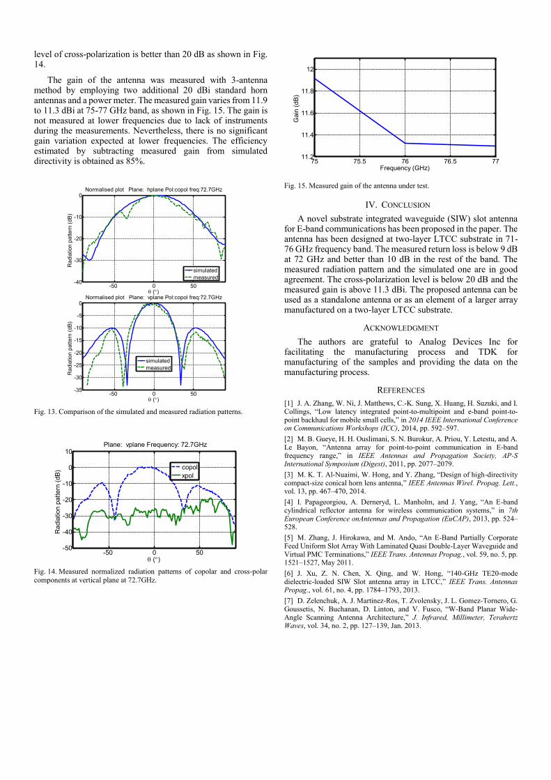
level of cross-polarization is better than 20 dB as shown in Fig. 14.
The gain of the antenna was measured with 3-antenna method by employing two additional 20 dBi standard horn antennas and a power meter. The measured gain varies from 11.9 to 11.3 dBi at 75-77 GHz band, as shown in Fig. 15. The gain is not measured at lower frequencies due to lack of instruments during the measurements. Nevertheless, there is no significant gain variation expected at lower frequencies. The efficiency estimated by subtracting measured gain from simulated directivity is obtained as 85%.
Fig. 13. Comparison of the simulated and measured radiation patterns.
Fig. 14. Measured normalized radiation patterns of copolar and cross-polar
components at vertical plane at 72.7GHz.
Fig. 15. Measured gain of the antenna under test.
IV. CONCLUSION
A novel substrate integrated waveguide (SIW) slot antenna for E-band communications has been proposed in the paper. The antenna has been designed at two-layer LTCC substrate in 71-76 GHz frequency band. The measured return loss is below 9 dB at 72 GHz and better than 10 dB in the rest of the band. The measured radiation pattern and the simulated one are in good agreement. The cross-polarization level is below 20 dB and the measured gain is above 11.3 dBi. The proposed antenna can be used as a standalone antenna or as an element of a larger array manufactured on a two-layer LTCC substrate.
ACKNOWLEDGMENT
The authors are grateful to Analog Devices Inc for facilitating the manufacturing process and TDK for manufacturing of the samples and providing the data on the manufacturing process.
REFERENCES
[1] J. A. Zhang, W. Ni, J. Matthews, C.-K. Sung, X. Huang, H. Suzuki, and I. Collings, “Low latency integrated point-to-multipoint and e-band point-to-point backhaul for mobile small cells,” in 2014 IEEE International Conference on Communications Workshops (ICC), 2014, pp. 592–597.
[2] M. B. Gueye, H. H. Ouslimani, S. N. Burokur, A. Priou, Y. Letestu, and A. Le Bayon, “Antenna array for point-to-point communication in E-band frequency range,” in IEEE Antennas and Propagation Society, AP-S International Symposium (Digest), 2011, pp. 2077–2079.
[3] M. K. T. Al-Nuaimi, W. Hong, and Y. Zhang, “Design of high-directivity compact-size conical horn lens antenna,” IEEE Antennas Wirel. Propag. Lett., vol. 13, pp. 467–470, 2014.
[4] I. Papageorgiou, A. Derneryd, L. Manholm, and J. Yang, “An E-band cylindrical reflector antenna for wireless communication systems,” in 7th European Conference onAntennas and Propagation (EuCAP), 2013, pp. 524–528.
[5] M. Zhang, J. Hirokawa, and M. Ando, “An E-Band Partially Corporate Feed Uniform Slot Array With Laminated Quasi Double-Layer Waveguide and Virtual PMC Terminations,” IEEE Trans. Antennas Propag., vol. 59, no. 5, pp. 1521–1527, May 2011.
[6] J. Xu, Z. N. Chen, X. Qing, and W. Hong, “140-GHz TE20-mode dielectric-loaded SIW Slot antenna array in LTCC,” IEEE Trans. Antennas Propag., vol. 61, no. 4, pp. 1784–1793, 2013.
[7] D. Zelenchuk, A. J. Martinez-Ros, T. Zvolensky, J. L. Gomez-Tornero, G. Goussetis, N. Buchanan, D. Linton, and V. Fusco, “W-Band Planar Wide-Angle Scanning Antenna Architecture,” J. Infrared, Millimeter, Terahertz Waves, vol. 34, no. 2, pp. 127–139, Jan. 2013.
-50 0 50-40
-30
-20
-10
0
()
Radia
tion p
attern
(dB
)
Normalised plot Plane: hplane Pol:copol freq:72.7GHz
simulated
measured
-50 0 50-35
-30
-25
-20
-15
-10
-5
0
()
Ra
dia
tion p
attern
(dB
)
Normalised plot Plane: vplane Pol:copol freq:72.7GHz
simulated
measured
-50 0 50-50
-40
-30
-20
-10
0
10
()
Ra
dia
tion p
attern
(dB
)
Plane: vplane Frequency: 72.7GHz
copol
xpol
75 75.5 76 76.5 7711.2
11.4
11.6
11.8
12
Frequency (GHz)
Gain
(dB
)