size enlargement, agglomeration · scarabaeus sacer adult beetle rolling its ball of dung (actual...
TRANSCRIPT
Fig. 7.1
Prof. Dr. J. Tomas, chair of Mechanical Process Engineering
Fig_MPE_7 VO Mechanical Process Engineering - Particle Technology Agglomeration Dr. W. Hintz/Prof. Dr. J. Tomas 23.06.2014 Figure 7.1
Size Enlargement,
Agglomeration
7. Particle formulation by agglomeration, 7.1 Fundamental agglomeration principles 7.2 Agglomerate strength 7.3 Pelletizing of moist powder 7.4 Press agglomeration
7.4.1 Powder compression and compaction behaviour 7.4.2 Briquetting and tabletting 7.4.3 Roller press
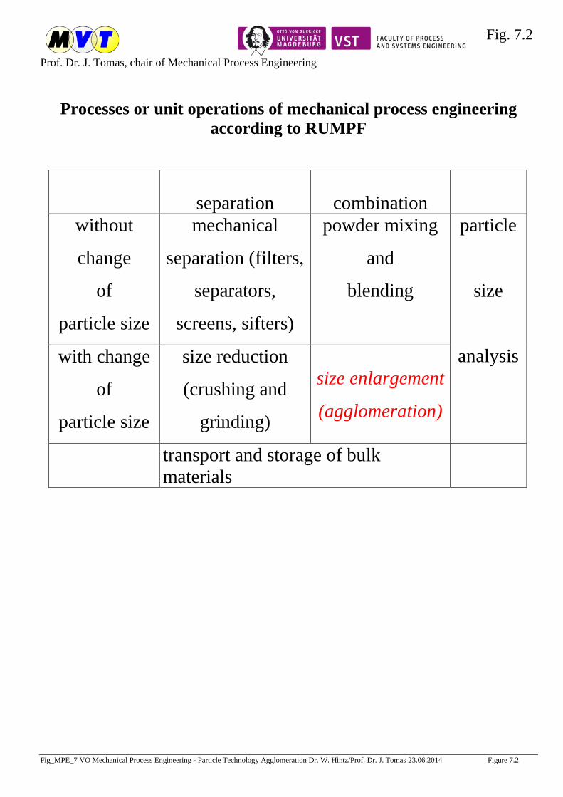
Fig. 7.2
Prof. Dr. J. Tomas, chair of Mechanical Process Engineering
Fig_MPE_7 VO Mechanical Process Engineering - Particle Technology Agglomeration Dr. W. Hintz/Prof. Dr. J. Tomas 23.06.2014 Figure 7.2
Processes or unit operations of mechanical process engineering according to RUMPF
separation
combination
without
change
of
particle size
mechanical
separation (filters,
separators,
screens, sifters)
powder mixing
and
blending
particle
size
analysis with change
of
particle size
size reduction
(crushing and
grinding)
size enlargement
(agglomeration)
transport and storage of bulk materials
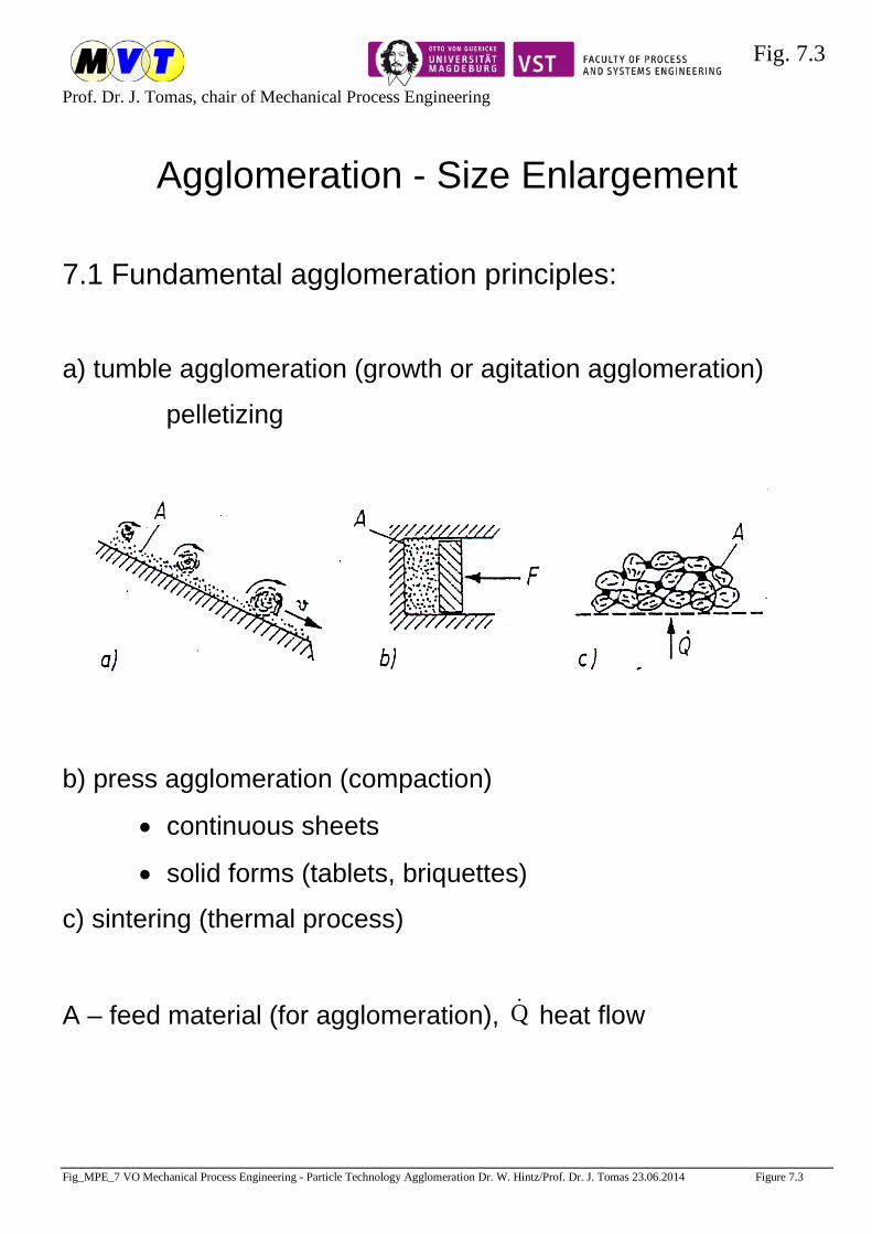
Fig. 7.3
Prof. Dr. J. Tomas, chair of Mechanical Process Engineering
Fig_MPE_7 VO Mechanical Process Engineering - Particle Technology Agglomeration Dr. W. Hintz/Prof. Dr. J. Tomas 23.06.2014 Figure 7.3
Agglomeration - Size Enlargement
7.1 Fundamental agglomeration principles:
a) tumble agglomeration (growth or agitation agglomeration)
pelletizing
b) press agglomeration (compaction)
• continuous sheets
• solid forms (tablets, briquettes)
c) sintering (thermal process)
A – feed material (for agglomeration), Q heat flow
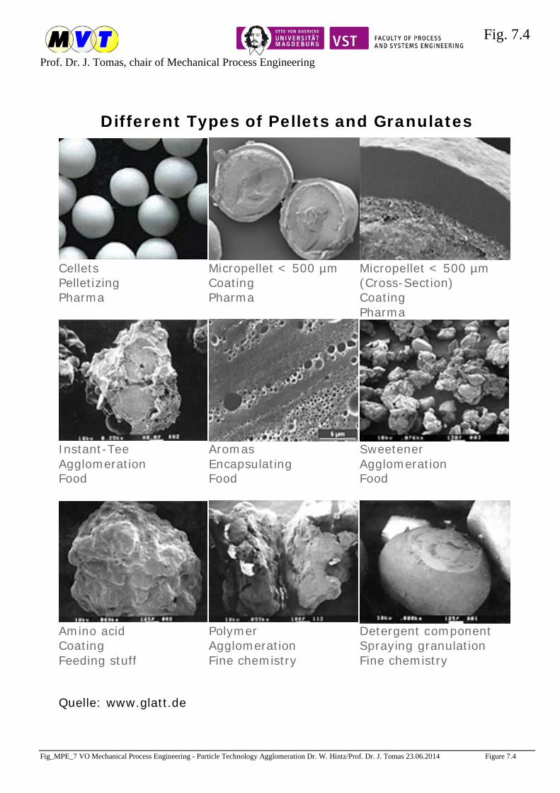
Fig. 7.4
Prof. Dr. J. Tomas, chair of Mechanical Process Engineering
Fig_MPE_7 VO Mechanical Process Engineering - Particle Technology Agglomeration Dr. W. Hintz/Prof. Dr. J. Tomas 23.06.2014 Figure 7.4
Different Types of Pellets and Granulates
Cellets Pelletizing Pharma
Micropellet < 500 µm Coating Pharma
Micropellet < 500 µm (Cross-Section) Coating Pharma
Instant-Tee Agglomeration Food
Aromas Encapsulating Food
Sweetener Agglomeration Food
Amino acid Coating Feeding stuff
Polymer Agglomeration Fine chemistry
Detergent component Spraying granulation Fine chemistry
Quelle: www.glatt.de
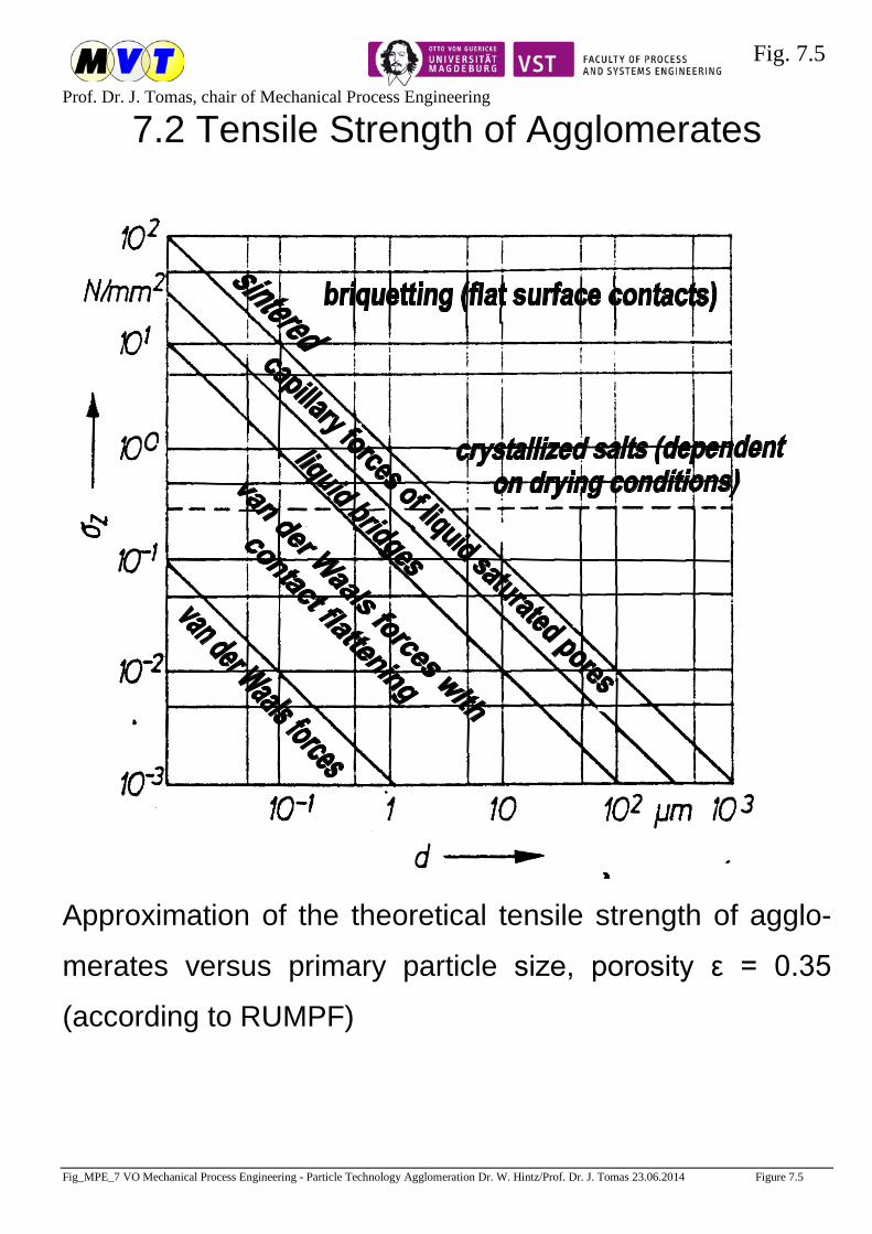
Fig. 7.5
Prof. Dr. J. Tomas, chair of Mechanical Process Engineering
Fig_MPE_7 VO Mechanical Process Engineering - Particle Technology Agglomeration Dr. W. Hintz/Prof. Dr. J. Tomas 23.06.2014 Figure 7.5
7.2 Tensile Strength of Agglomerates
Approximation of the theoretical tensile strength of agglo-
merates versus primary particle size, porosity ε = 0.35
(according to RUMPF)
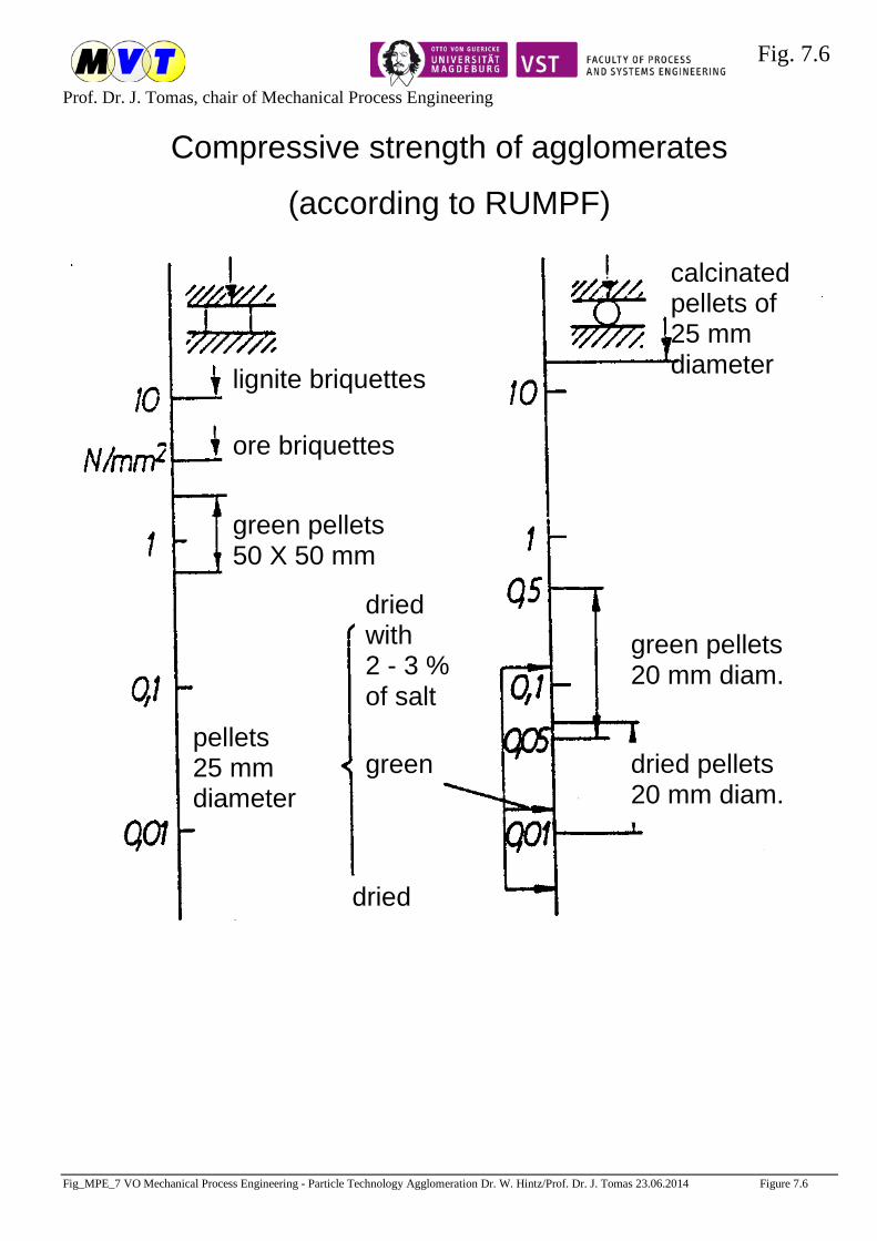
Fig. 7.6
Prof. Dr. J. Tomas, chair of Mechanical Process Engineering
Fig_MPE_7 VO Mechanical Process Engineering - Particle Technology Agglomeration Dr. W. Hintz/Prof. Dr. J. Tomas 23.06.2014 Figure 7.6
Compressive strength of agglomerates
(according to RUMPF)
pellets 25 mm diameter
dried
dried with 2 - 3 % of salt
green dried pellets 20 mm diam.
green pellets 20 mm diam.
green pellets 50 X 50 mm
ore briquettes
lignite briquettes
calcinated pellets of 25 mm diameter
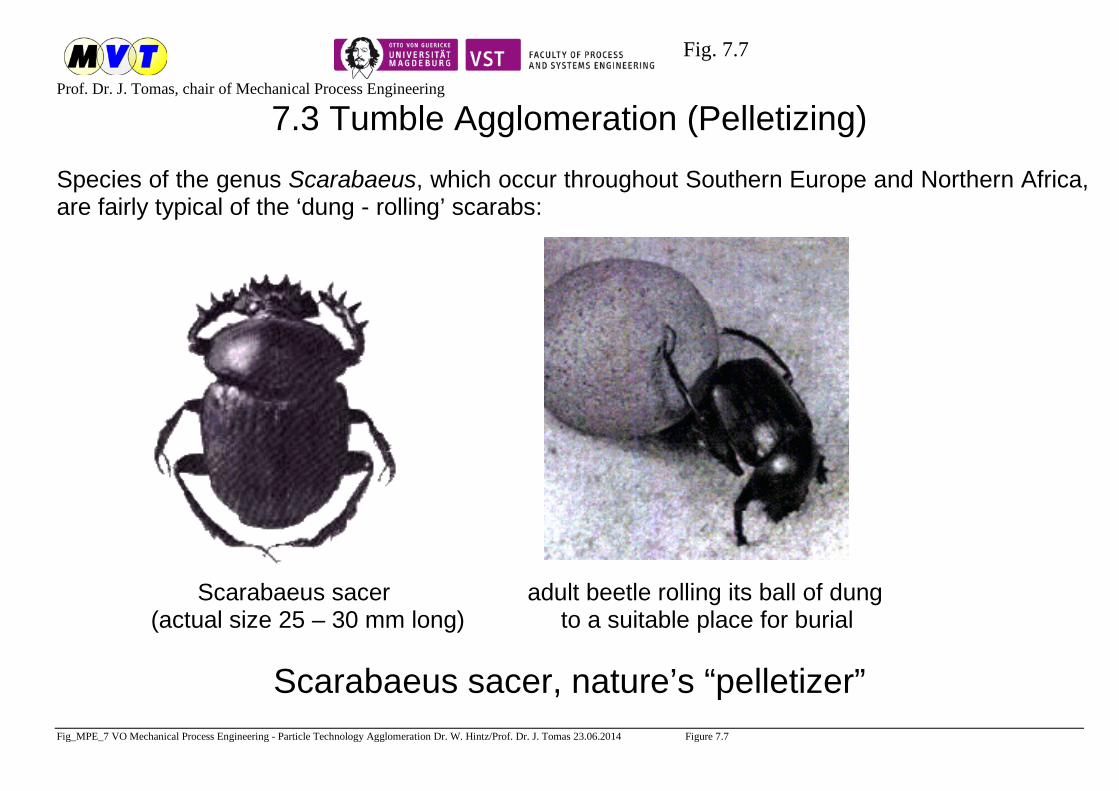
Fig. 7.7
Prof. Dr. J. Tomas, chair of Mechanical Process Engineering
Fig_MPE_7 VO Mechanical Process Engineering - Particle Technology Agglomeration Dr. W. Hintz/Prof. Dr. J. Tomas 23.06.2014 Figure 7.7
7.3 Tumble Agglomeration (Pelletizing)
Species of the genus Scarabaeus, which occur throughout Southern Europe and Northern Africa, are fairly typical of the ‘dung - rolling’ scarabs: Scarabaeus sacer adult beetle rolling its ball of dung (actual size 25 – 30 mm long) to a suitable place for burial
Scarabaeus sacer, nature’s “pelletizer”

Fig. 7.8
Prof. Dr. J. Tomas, chair of Mechanical Process Engineering
Fig_MPE_7 VO Mechanical Process Engineering - Particle Technology Agglomeration Dr. W. Hintz/Prof. Dr. J. Tomas 23.06.2014 Figure 7.8
7.3 Tumble Agglomeration (Pelletizing) 1. Balling drum and balling pan
a) balling drum b) balling pan A feed material P green pellets W water

Fig. 7.9
Prof. Dr. J. Tomas, chair of Mechanical Process Engineering
Fig_MPE_7 VO Mechanical Process Engineering - Particle Technology Agglomeration Dr. W. Hintz/Prof. Dr. J. Tomas 23.06.2014 Figure 7.9
Models of pellet nucleation and pellet formation mechanism
a) Pellet nucleation mechanism b) Embedding of small feed particles at the surface of wet
agglomerates (acc. to Pietsch, Aufbereitungstechnik 7 (1966) 177-191)
liquid solid

Fig. 7.10
Prof. Dr. J. Tomas, chair of Mechanical Process Engineering
Fig_MPE_7 VO Mechanical Process Engineering - Particle Technology Agglomeration Dr. W. Hintz/Prof. Dr. J. Tomas 23.06.2014 Figure 7.10
Balling pan pelletizer
Inclined pan pelletizer 1. pan 5. device for changing the
2. pan drive pan angle of inclination
3. water supply (tilt angle to the horizontal)
4. bottom share
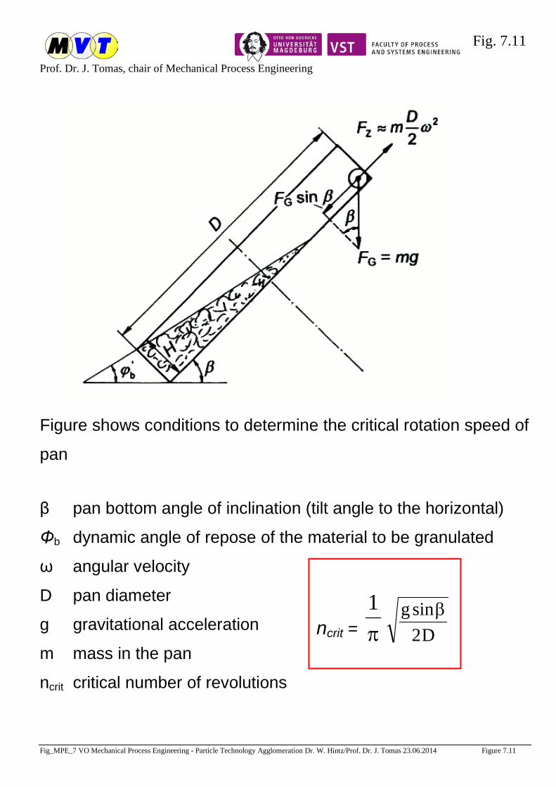
Fig. 7.11
Prof. Dr. J. Tomas, chair of Mechanical Process Engineering
Fig_MPE_7 VO Mechanical Process Engineering - Particle Technology Agglomeration Dr. W. Hintz/Prof. Dr. J. Tomas 23.06.2014 Figure 7.11
ncrit = π1
D2sing β
Figure shows conditions to determine the critical rotation speed of
pan
β pan bottom angle of inclination (tilt angle to the horizontal)
Φb dynamic angle of repose of the material to be granulated
ω angular velocity
D pan diameter
g gravitational acceleration
m mass in the pan
ncrit critical number of revolutions
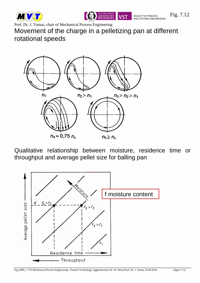
Fig. 7.12
Prof. Dr. J. Tomas, chair of Mechanical Process Engineering
Fig_MPE_7 VO Mechanical Process Engineering - Particle Technology Agglomeration Dr. W. Hintz/Prof. Dr. J. Tomas 23.06.2014 Figure 7.12
Movement of the charge in a pelletizing pan at different rotational speeds
Qualitative relationship between moisture, residence time or throughput and average pellet size for balling pan
f moisture content

Fig. 7.13
Prof. Dr. J. Tomas, chair of Mechanical Process Engineering
Fig_MPE_7 VO Mechanical Process Engineering - Particle Technology Agglomeration Dr. W. Hintz/Prof. Dr. J. Tomas 23.06.2014 Figure 7.13
Deep dish or pan pelletizer
1 disc
2 screw conveyor
3 water supply
A feed
P green product
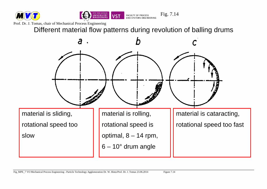
Fig. 7.14
Prof. Dr. J. Tomas, chair of Mechanical Process Engineering
Fig_MPE_7 VO Mechanical Process Engineering - Particle Technology Agglomeration Dr. W. Hintz/Prof. Dr. J. Tomas 23.06.2014 Figure 7.14
Different material flow patterns during revolution of balling drums
material is sliding,
rotational speed too
slow
material is rolling,
rotational speed is
optimal, 8 – 14 rpm,
6 – 10° drum angle
material is cataracting,
rotational speed too fast
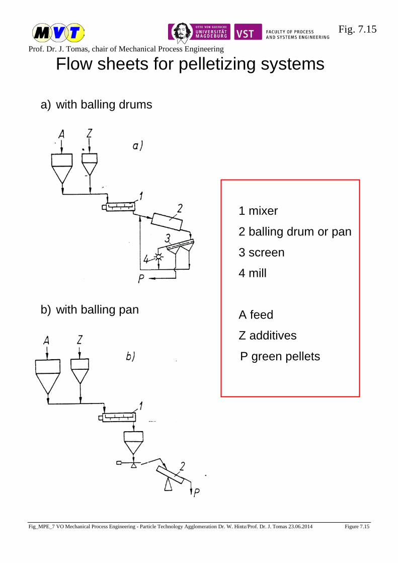
Fig. 7.15
Prof. Dr. J. Tomas, chair of Mechanical Process Engineering
Fig_MPE_7 VO Mechanical Process Engineering - Particle Technology Agglomeration Dr. W. Hintz/Prof. Dr. J. Tomas 23.06.2014 Figure 7.15
Flow sheets for pelletizing systems a) with balling drums
b) with balling pan
1 mixer
2 balling drum or pan
3 screen
4 mill
A feed
Z additives
P green pellets

Fig. 7.16
Prof. Dr. J. Tomas, chair of Mechanical Process Engineering
Fig_MPE_7 VO Mechanical Process Engineering - Particle Technology Agglomeration Dr. W. Hintz/Prof. Dr. J. Tomas 23.06.2014 Figure 7.16
7.4 Press Agglomeration Operation principles of press agglomeration : a) b) c)
a) in a closed die
b) in a open die
c) by roller pressure
A feed
B agglomerate
FP compaction or press force
FR wall friction force in the die
channel
h punch stroke length
l filling level (not compacted)
s thickness of compacted
material
k compaction (k=l/s)
β1 half of nip angle
1 punch
2 pressing die

Fig. 7.17
Prof. Dr. J. Tomas, chair of Mechanical Process Engineering
Fig_MPE_7 VO Mechanical Process Engineering - Particle Technology Agglomeration Dr. W. Hintz/Prof. Dr. J. Tomas 23.06.2014 Figure 7.17
bulk
den
sity
ρb
ρb,0
ρb = ρb,0 · (1 + )σM,stσ0
n
centre stress during consolidationor steady-state flow σM,st
isostatictensile strength -σ0
0
n = 0 incompressible
0 < n < 1 compressible
n = 1 ideal gas compressibility index
Isentropic Powder Compression
Adiabatic gas compression:
pV1
dpdV
adκ=−
(1)
Isentropic powder compression:
∫∫σρ
ρ σ+σσ
⋅=ρρ st,Mb
0,b 0 0st,M
st,M
b
b dnd
(2)
Compressibility index of powders, semi-empirical estimation
index n evaluation examples flowability 0 – 0.01 incompressible gravel free flowing
0.01 – 0.05 low compressibility fine sand 0.05 - 0.1 compressible dry powder cohesive
0.1 - 1 very compressible moist powder very cohesive
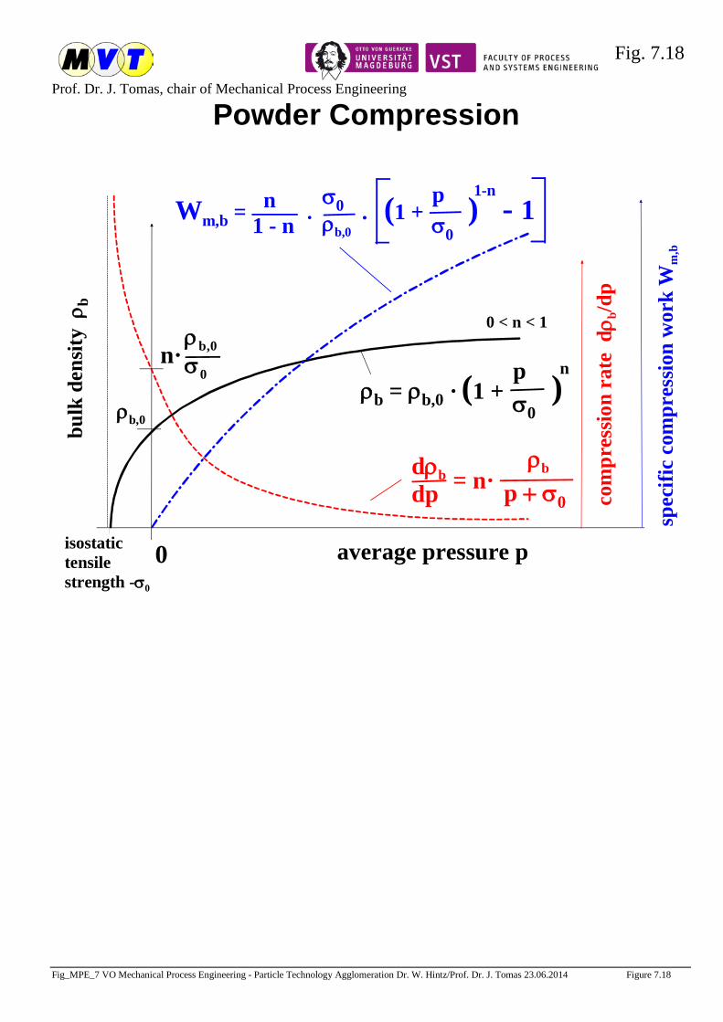
Fig. 7.18
Prof. Dr. J. Tomas, chair of Mechanical Process Engineering
Fig_MPE_7 VO Mechanical Process Engineering - Particle Technology Agglomeration Dr. W. Hintz/Prof. Dr. J. Tomas 23.06.2014 Figure 7.18
bulk
den
sity
ρb
ρb,0
average pressure pisostatictensilestrength -σ0
0
0 < n < 1
Powder Compression
ρb = ρb,0 · (1 + )pσ0
n
com
pres
sion
rate
dρ b
/dp
ρb
p + σ0= n· dρb
dp
Wm,b = . . (1 + ) - 1pσ0
1-n n1 - n
σ0ρb,0
spec
ific
com
pres
sion
wor
k W
m,b
ρb,0σ0
n·

Fig. 7.19
Prof. Dr. J. Tomas, chair of Mechanical Process Engineering
Fig_MPE_7 VO Mechanical Process Engineering - Particle Technology Agglomeration Dr. W. Hintz/Prof. Dr. J. Tomas 23.06.2014 Figure 7.19
average pressure at steady-state flow σM,stisostatictensile strength -σ0
0
0 < n < 1
Compression and Preshear Work
Wm,b = . . (1 + ) - 1σM,st
σ0
1-n n1 - n
σ0ρb,0
spec
ific
com
pres
sion
and
pres
hear
wor
k W
m,b, W
m,b
,pre Wm,b,pre = (1 + )σM,st
σ0
1-nspre. sin 2ϕst
2 . hSz
σ0
ρb,0
displacement s
shea
r fo
rce
FS
preshear
spre
τpre, YL3
Wb, pre = ∫ FS(s) ds
τpre, YL2
τpre, YL1
FN
FS
s
spre. sin 2ϕst
2 . hSz
σ0
ρb,0
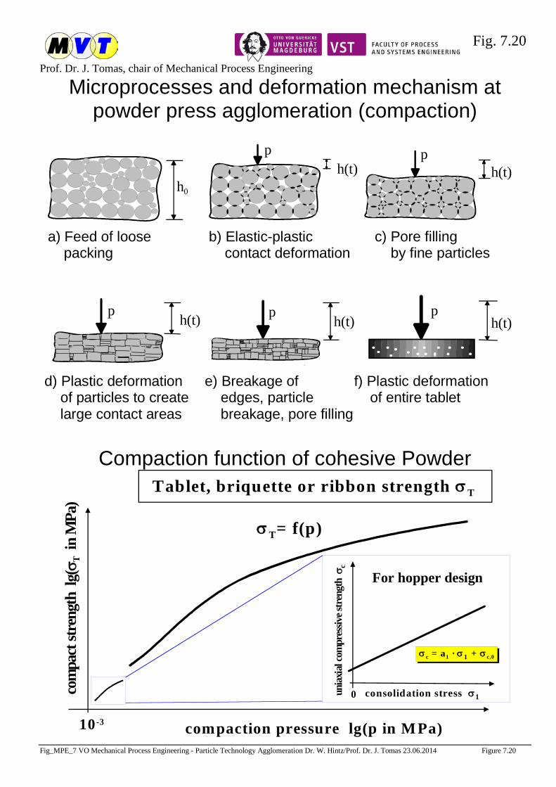
Fig. 7.20
Prof. Dr. J. Tomas, chair of Mechanical Process Engineering
Fig_MPE_7 VO Mechanical Process Engineering - Particle Technology Agglomeration Dr. W. Hintz/Prof. Dr. J. Tomas 23.06.2014 Figure 7.20
Microprocesses and deformation mechanism at powder press agglomeration (compaction)
pp
d) Plastic deformation of particles to create large contact areas
f) Plastic deformation of entire tablet
e) Breakage of edges, particle breakage, pore filling
p
p
b) Elastic-plastic contact deformation
a) Feed of loose packing
c) Pore filling by fine particles
p
h0
h(t)
h(t)
h(t)
h(t)
h(t)
Compaction function of cohesive Powder
com
pact
stre
ngth
lg(
σ T i
n M
Pa)
compaction pressure lg(p in M Pa)10-3
Tablet, briquette or ribbon strength σT
unia
xial
com
pres
sive s
tren
gth
σc
consolidation stress σ10
σ c = a1 · σ1 + σ c,0
For hopper design
σT= f(p)
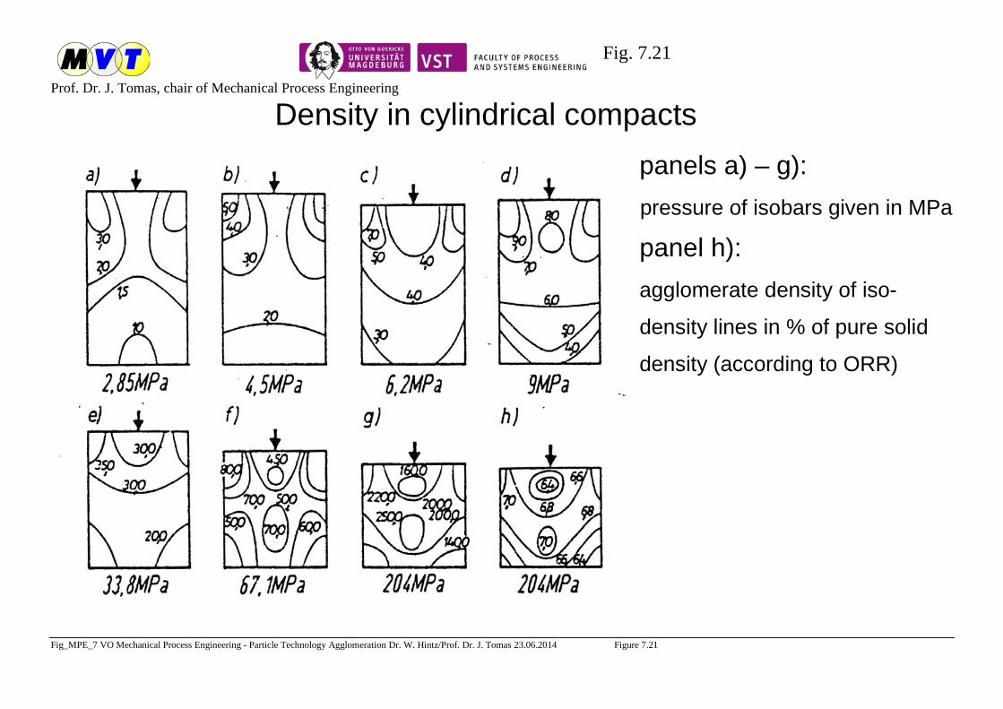
Fig. 7.21
Prof. Dr. J. Tomas, chair of Mechanical Process Engineering
Fig_MPE_7 VO Mechanical Process Engineering - Particle Technology Agglomeration Dr. W. Hintz/Prof. Dr. J. Tomas 23.06.2014 Figure 7.21
Density in cylindrical compacts panels a) – g): pressure of isobars given in MPa
panel h): agglomerate density of iso-
density lines in % of pure solid
density (according to ORR)
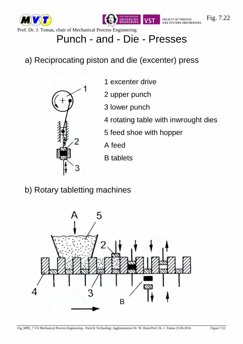
Fig. 7.22
Prof. Dr. J. Tomas, chair of Mechanical Process Engineering
Fig_MPE_7 VO Mechanical Process Engineering - Particle Technology Agglomeration Dr. W. Hintz/Prof. Dr. J. Tomas 23.06.2014 Figure 7.22
Punch - and - Die - Presses
a) Reciprocating piston and die (excenter) press
1 excenter drive
2 upper punch
3 lower punch
4 rotating table with inwrought dies
5 feed shoe with hopper
A feed
B tablets
b) Rotary tabletting machines
B

Fig. 7.23
Prof. Dr. J. Tomas, chair of Mechanical Process Engineering
Fig_MPE_7 VO Mechanical Process Engineering - Particle Technology Agglomeration Dr. W. Hintz/Prof. Dr. J. Tomas 23.06.2014 Figure 7.23
Pelletizing machines
1 cutter A feed B briquettes a) ram extrusion or plunger press
b) screw extruder
c) pelleting machine with flat die and muller-type press rollers
d) pelleting machine with one solid and one hollow roll
e) pelleting machine with two hollow rolls
f) pelleting machine with internal press roll
g) gear-type pelletizer

Fig. 7.24
Prof. Dr. J. Tomas, chair of Mechanical Process Engineering
Fig_MPE_7 VO Mechanical Process Engineering - Particle Technology Agglomeration Dr. W. Hintz/Prof. Dr. J. Tomas 23.06.2014 Figure 7.24
Compaction mechanism in a ram press
Sequence of events during a briquetting cycle in the ram press
(according to KEGEL and RAMMLER)
pressure filling filling
begin of stroke
back expansion begin of compaction
begin of pre-filling
begin of back stroke
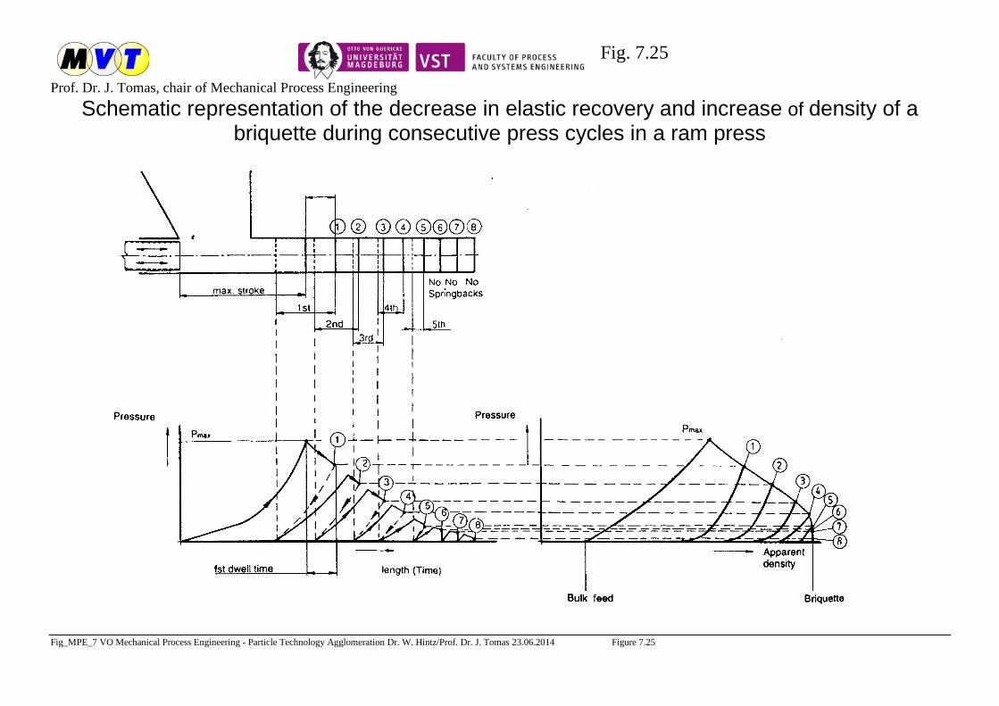
Fig. 7.25
Prof. Dr. J. Tomas, chair of Mechanical Process Engineering
Fig_MPE_7 VO Mechanical Process Engineering - Particle Technology Agglomeration Dr. W. Hintz/Prof. Dr. J. Tomas 23.06.2014 Figure 7.25
Schematic representation of the decrease in elastic recovery and increase of density of a briquette during consecutive press cycles in a ram press
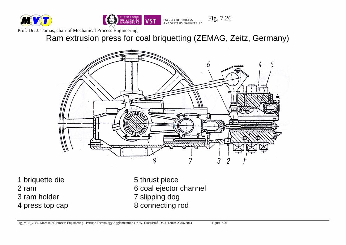
Fig. 7.26
Prof. Dr. J. Tomas, chair of Mechanical Process Engineering
Fig_MPE_7 VO Mechanical Process Engineering - Particle Technology Agglomeration Dr. W. Hintz/Prof. Dr. J. Tomas 23.06.2014 Figure 7.26
Ram extrusion press for coal briquetting (ZEMAG, Zeitz, Germany)
1 briquette die 5 thrust piece 2 ram 6 coal ejector channel 3 ram holder 7 slipping dog 4 press top cap 8 connecting rod
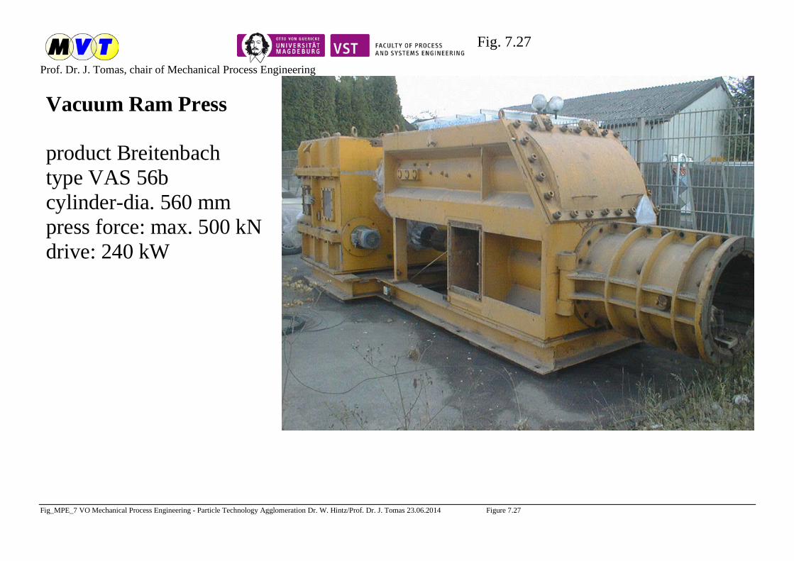
Fig. 7.27
Prof. Dr. J. Tomas, chair of Mechanical Process Engineering
Fig_MPE_7 VO Mechanical Process Engineering - Particle Technology Agglomeration Dr. W. Hintz/Prof. Dr. J. Tomas 23.06.2014 Figure 7.27
Vakuumstrangpresse
Fabrikat BreitenbachTyp VAS 56bZylinder-Ø: 560 mmLeistung: max. 50 to./Antriebsmotor: 240 KW
Vacuum Ram Press
product Breitenbachtype VAS 56bcylinder-dia. 560 mmpress force: max. 500 kNdrive: 240 kW
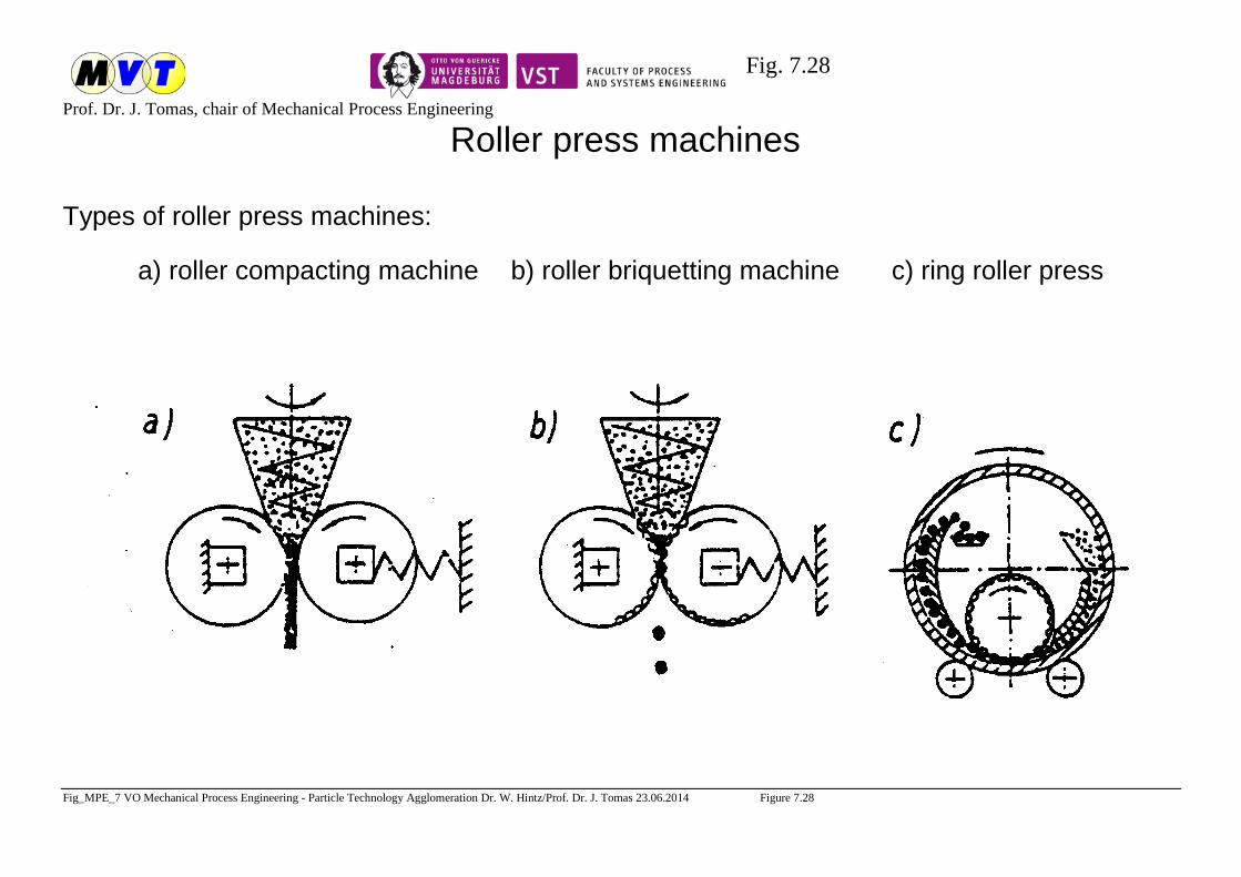
Fig. 7.28
Prof. Dr. J. Tomas, chair of Mechanical Process Engineering
Fig_MPE_7 VO Mechanical Process Engineering - Particle Technology Agglomeration Dr. W. Hintz/Prof. Dr. J. Tomas 23.06.2014 Figure 7.28
Roller press machines
Types of roller press machines:
a) roller compacting machine b) roller briquetting machine c) ring roller press
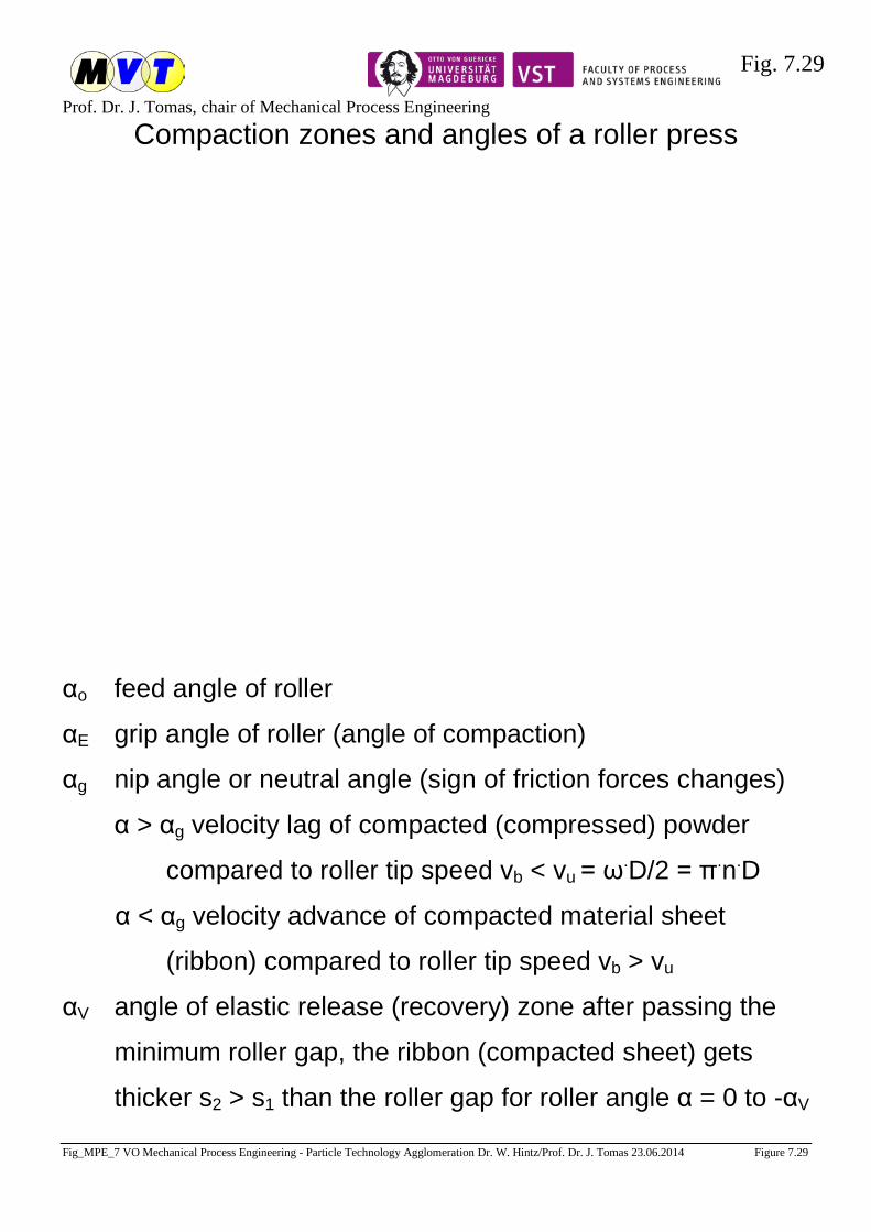
Fig. 7.29
Prof. Dr. J. Tomas, chair of Mechanical Process Engineering
Fig_MPE_7 VO Mechanical Process Engineering - Particle Technology Agglomeration Dr. W. Hintz/Prof. Dr. J. Tomas 23.06.2014 Figure 7.29
Compaction zones and angles of a roller press
αo feed angle of roller
αE grip angle of roller (angle of compaction)
αg nip angle or neutral angle (sign of friction forces changes)
α > αg velocity lag of compacted (compressed) powder
compared to roller tip speed vb < vu = ω.D/2 = π.n.D
α < αg velocity advance of compacted material sheet
(ribbon) compared to roller tip speed vb > vu
αV angle of elastic release (recovery) zone after passing the
minimum roller gap, the ribbon (compacted sheet) gets
thicker s2 > s1 than the roller gap for roller angle α = 0 to -αV
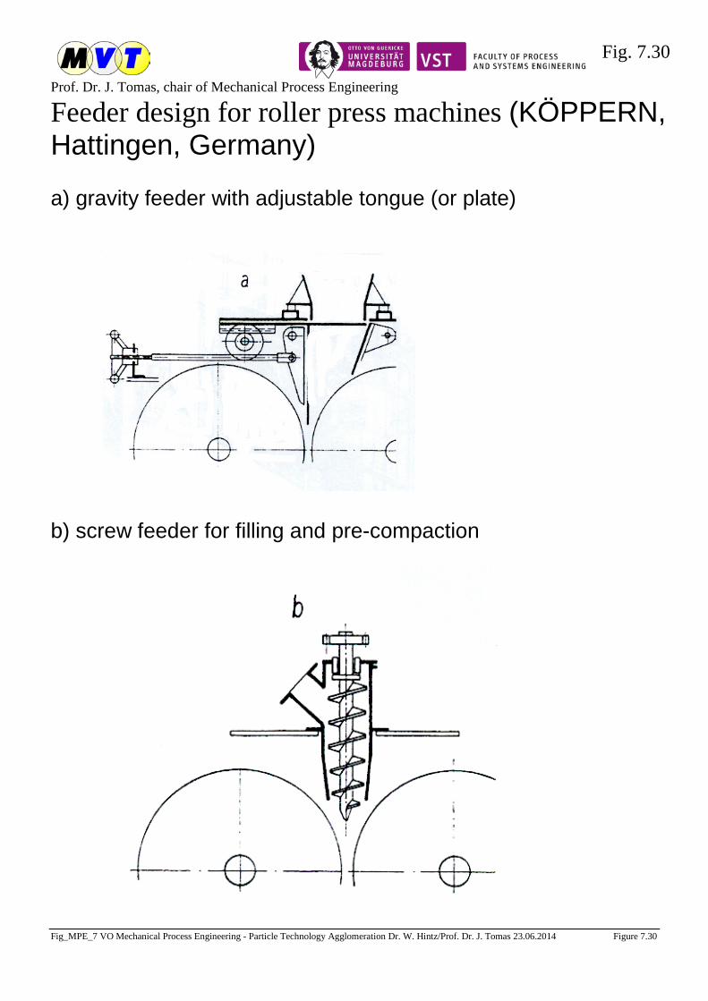
Fig. 7.30
Prof. Dr. J. Tomas, chair of Mechanical Process Engineering
Fig_MPE_7 VO Mechanical Process Engineering - Particle Technology Agglomeration Dr. W. Hintz/Prof. Dr. J. Tomas 23.06.2014 Figure 7.30
Feeder design for roller press machines (KÖPPERN, Hattingen, Germany)
a) gravity feeder with adjustable tongue (or plate)
b) screw feeder for filling and pre-compaction

Fig. 7.31
Prof. Dr. J. Tomas, chair of Mechanical Process Engineering
Fig_MPE_7 VO Mechanical Process Engineering - Particle Technology Agglomeration Dr. W. Hintz/Prof. Dr. J. Tomas 23.06.2014 Figure 7.31
Roller press (KÖPPERN, Hattingen, Germany)
1 rollers with replaceable rings or sleeves as pressing tools 4 hydraulic reservoir
2 roller core with integral journals 5 hydraulic pump
3 hydraulic cylinder 6 automatic grease lubrication