ska exascale software challenges
TRANSCRIPT
SKA memo 128 SKA Exascale Software Challenges Tim Cornwell, ATNF/CASS Ben Humphreys, ATNF/CASS Whitepaper submitted to International Exascale Software Project, October 2010
2010-10-14
SKA Exascale Software Challenges• 2010/10/12, Version 1.0 Page 2
1. THE SQUARE KILOMETRE ARRAY The proposed Square Kilometre Array will bring a huge improvement in both the sensitivity and field of view over existing radio telescopes. SKA is being developed by an international consortium, and is expected to become fully operational by the end of the decade.
The SKA science goals have been developed over a number of years by a large number of astronomers from around the world. These goals can be summarized by a number of questions.
• Probing the Dark Ages: when & how were the first stars formed?
• Cosmology and Galaxy Evolution: what is the nature of Dark Energy and Dark Matter?
• Strong-field tests of General Relativity: was Einstein correct?
• Origin and Evolution of Cosmic Magnetism: where does magnetism come from?
• Cradle of Life: what and where are the conditions for life?
The science goals for the SKA cannot be met by any one design. For example, the requirement to span observing frequencies from 70MHz to 25GHz requires at least two solutions – arrays of dipoles for low frequencies, and paraboloidal reflectors at high frequencies. Innovation is required in many areas, either to reduce the cost of existing solutions (as in antennas) or to invent new solutions (as for wide field of view on paraboloid antennas).
The SKA at mid and low frequencies will be constructed in two distinct phases, the first being a subset of the second. This document focuses on the main scientific goals and baseline technical concept for the SKA Phase 1 (SKA1). The major science goals for SKA1 will be to study the history and role of neutral Hydrogen in the Universe from the dark ages to the present-day, and to employ pulsars as probes of fundamental physics. The baseline technical concept of SKA1 will include a sparse aperture array operating at frequencies up to 450 MHz, and an array of dishes, operating at frequencies up to 3 GHz. It is planned that onstruction will take place in 2016-2019 at an estimated cost of 350M€. The SKA1 facility will represent a major step forward in terms of sensitivity, survey speed, image fidelity, temporal resolution, and field-of-view. It will open up new areas of discovery space and demonstrate the science and technology underpinning the SKA Phase 2 (SKA2).
SKA1 is planned to be comprised of two components:
• A low-frequency sparse aperture array with an A/Tsys of ~ 2000 m2/K operating at frequencies between 70 and 450 MHz. The array will be centrally condensed but some of the collecting area will be in stations located out to a maximum distance of 100 km from the core, and
• A dish array with Aeff/Tsys of ~1000 m2/K using approximately two hundred and fifty 15-metre antennas, employing a “first-light” instrumentation package that will use single-pixel feeds to provide high sensitivity and excellent polarisation characteristics over a frequency range of 0.45-3 GHz. The array will be centrally condensed but some of the collecting area will be co-located with the sparse aperture array stations out to a maximum distance of 100 km from the core.
Planning is currently focusing on producing a costed design. This work is led by the SKA Project Development Office in Manchester, UK, with contributions from organisations around the world. In 2012, we expect that SKA to proceed to a pre-construction phase, with construction of SKA1 starting in 2016.
The development of SKA requires solution of a number of technical challenges. For example, to meet the budget, inexpensive yet high quality antennas must be available. Similarly, the electronic packages on the telescope must be low cost yet high performance. Moving data around from the sensors to the digital signal and imaging processing systems is a very
SKA Exascale Software Challenges• 2010/10/12, Version 1.0 Page 3
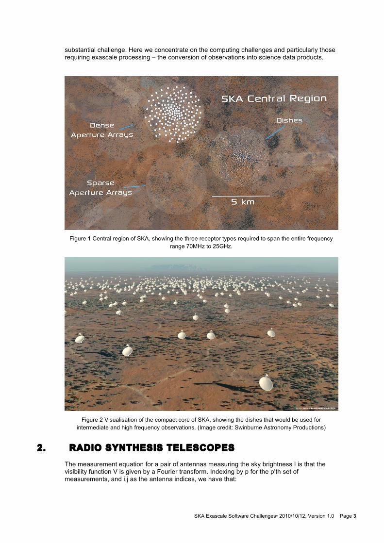
substantial challenge. Here we concentrate on the computing challenges and particularly those requiring exascale processing – the conversion of observations into science data products.
Figure 1 Central region of SKA, showing the three receptor types required to span the entire frequency
range 70MHz to 25GHz.
Figure 2 Visualisation of the compact core of SKA, showing the dishes that would be used for
intermediate and high frequency observations. (Image credit: Swinburne Astronomy Productions)
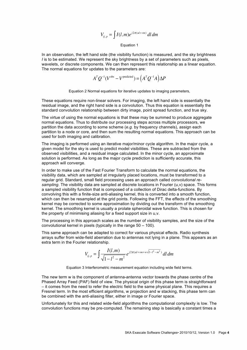
2. RADIO SYNTHESIS TELESCOPES The measurement equation for a pair of antennas measuring the sky brightness I is that the visibility function V is given by a Fourier transform. Indexing by p for the p’th set of measurements, and i,j as the antenna indices, we have that:
SKA Exascale Software Challenges• 2010/10/12, Version 1.0 Page 4
Vij , p = I(l,m)e j2π (ul+vm ) dl dm∫
Equation 1
In an observation, the left hand side (the visibility function) is measured, and the sky brightness I is to be estimated. We represent the sky brightness by a set of parameters such as pixels, wavelets, or discrete components. We can then represent this relationship as a linear equation. The normal equations for updates to the parameters are:
ATQ−1(V obs −V predicted ) = ATQ−1A( )ΔP
Equation 2 Normal equations for iterative updates to imaging parameters,
These equations require non-linear solvers. For imaging, the left hand side is essentially the residual image, and the right hand side is a convolution. Thus this equation is essentially the standard convolution relationship between dirty image, point spread function, and true sky.
The virtue of using the normal equations is that these may be summed to produce aggregate normal equations. Thus to distribute our processing steps across multiple processors, we partition the data according to some scheme (e.g. by frequency channels), assign each partition to a node or core, and then sum the resulting normal equations. This approach can be used for both imaging and calibration.
The imaging is performed using an iterative major/minor cycle algorithm. In the major cycle, a given model for the sky is used to predict model visibilities. These are subtracted from the observed visibilities, and a residual image calculated. In the minor cycle, an approximate solution is performed. As long as the major cycle prediction is sufficiently accurate, this approach will converge.
In order to make use of the Fast Fourier Transform to calculate the normal equations, the visibility data, which are sampled at irregularly placed locations, must be transformed to a regular grid. Standard, small field processing uses an approach called convolutional re-sampling. The visibility data are sampled at discrete locations in Fourier (u,v) space. This forms a sampled visibility function that is composed of a collection of Dirac delta-functions. By convolving this with a finite-size anti-aliasing kernel, this is converted into a smooth function, which can then be resampled at the grid points. Following the FFT, the effects of the smoothing kernel may be corrected to some approximation by dividing out the transform of the smoothing kernel. The smoothing kernel is usually a prolate spheroidal wave function. This is chosen for the property of minimising aliasing for a fixed support size in u,v.
The processing in this approach scales as the number of visibility samples, and the size of the convolutional kernel in pixels (typically in the range 50 – 100).
This same approach can be adapted to correct for various physical effects. Radio synthesis arrays suffer from wide-field aberration due to antennas not lying in a plane. This appears as an extra term in the Fourier relationship.
Vij , p =I(l,m)1− l2 − m2
e j2π (ul+vm+w 1− l2 −m2 ) dl dm∫
Equation 3 Interferometric measurement equation including wide field terms.
The new term w is the component of antenna-antenna vector towards the phase centre of the Phased Array Feed (PAF) field of view. The physical origin of this phase term is straightforward – it comes from the need to refer the electric field to the same physical plane. This requires a Fresnel term. In the most efficient algorithms, w projection and w stacking, this phase term can be combined with the anti-aliasing filter, either in image or Fourier space.
Unfortunately for this and related wide-field algorithms the computational complexity is low. The convolution functions may be pre-computed. The remaining step is basically a constant times a
SKA Exascale Software Challenges• 2010/10/12, Version 1.0 Page 5
vector plus a vector (CAXPY) with arrays that are generally too large to fit in currently available L2 or L3 cache.
3. HPC IN RADIO ASTRONOMY Until recently, practical experience with tera-scale and peta-scale processing in radio astronomy has been limited. However, the advent of SKA and the associated pathfinders has led to a substantial increase in development of HPC capabilities. The two telescopes currently pushing up to 100TFlop/s are the Low Frequency Array (LOFAR), and the Australian Square Kilometre Array Pathfinder (ASKAP). Additionally, a number of institutes are researching and applying cluster and/or GPU processing techniques at various scales. In this paper, we concentrate on the HPC requirements for ASKAP. LOFAR HPC requirements are similar in scale, and there is substantial information, design, and code sharing between ASKAP and LOFAR.
ASKAP is currently being built by CSIRO in Western Australia. ASKAP is targeted to observe at frequencies between 0.7 and 1.8 GHz, looking principally at neutral hydrogen (HI) at red shifts up to z~1. ASKAP will be composed of up to 36 antennas, each of 12m diameter, and there will be a 36 beam phased array feed on each antenna. ASKAP is expected to start scientific observations in 2012/2013. The goal of ASKAP is to demonstrate three main points:
• Western Australia can support a world-class radio astronomical facility,
• A wide-field of view (30 square degrees) can be obtained by the use of phased array feeds (PAF) on standard parabolic radio antennas,
• The computing for wide field of view imaging is feasible.
It is the latter point that is most relevant here. For perspective, we note that the processing required for a synthesis radio telescope goes as the square or cube of the maximum baseline (depending on context), the square of the number of antennas and as first power of the field of view. Thus to first order, if SKA1 uses the same wide-field technology as ASKAP and on baselines up to 50km, the high spectral frequency resolution processing for SKA1 will be about 10EF.
Construction started in July 2006, and will proceed to a 6 antenna prototype in 2011, and a full system in mid 2013. The science case for the telescope has been developed by an international team. Some of the key scientific goals are:
• Survey HI emission from 1.7 million galaxies up z ~ 0.3
• Deep continuum survey of entire sky ~ 10uJy
• Polarimetry over entire sky
Since ASKAP is intrinsically wide field of view, it is envisaged mainly to operate as a survey telescope with limited time available for pointed observations.
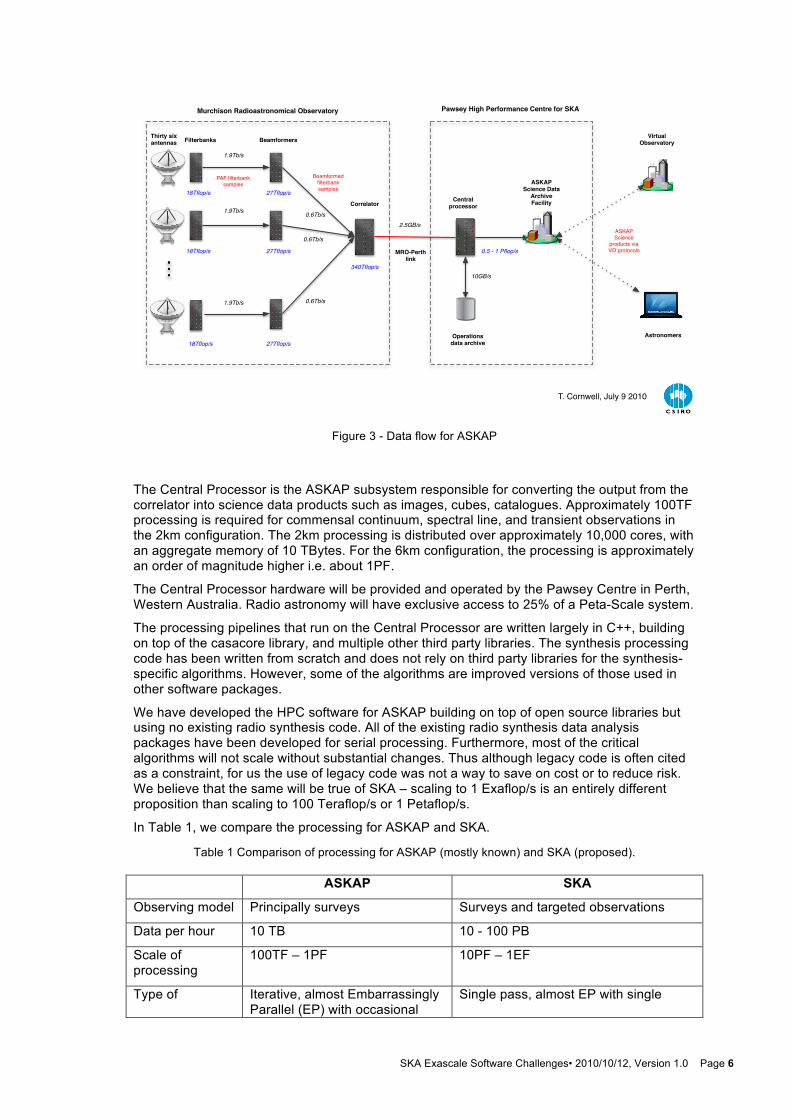
The full data path shows two concentrations of processing. The filter banks in each antenna select signals in 304 1MHz sub-bands from each PAF element. These are sent to the beam former for summation into primary beams. The signals from all primary beams from each antenna are then sent to the correlator, where all correlations between equivalent beams are calculated, producing correlations (visibilities). The visibilities are then sent to the Central Processor for processing into image-based science results. The signal processing elements are all in the left hand box. These are implemented in custom FPGA-based hardware. Image processing occurs on the right hand side in a typical cluster or supercomputer.
The signal processing (on the left) must occur in real time since the input data rate is 72Tb/s. For the new generation of telescopes, including ASKAP and SKA, the image processing (on the right) must also proceed in real time. This is dictated by the data rate – in full spectral line mode, the data rate from the ASKAP correlator is about 2.8 GBytes per second. A typical 8-hour observation will therefore consume about 100 TBytes of storage. Thus, for example, 1 PByte disk storage would fill up in just over two days. Necessarily, then, our model is to process observations as they occur. Editing, calibration, averaging, imaging, and source cataloguing must occur in near-real time as the observations are taken.
SKA Exascale Software Challenges• 2010/10/12, Version 1.0 Page 6
Figure 3 - Data flow for ASKAP
The Central Processor is the ASKAP subsystem responsible for converting the output from the correlator into science data products such as images, cubes, catalogues. Approximately 100TF processing is required for commensal continuum, spectral line, and transient observations in the 2km configuration. The 2km processing is distributed over approximately 10,000 cores, with an aggregate memory of 10 TBytes. For the 6km configuration, the processing is approximately an order of magnitude higher i.e. about 1PF.
The Central Processor hardware will be provided and operated by the Pawsey Centre in Perth, Western Australia. Radio astronomy will have exclusive access to 25% of a Peta-Scale system.
The processing pipelines that run on the Central Processor are written largely in C++, building on top of the casacore library, and multiple other third party libraries. The synthesis processing code has been written from scratch and does not rely on third party libraries for the synthesis-specific algorithms. However, some of the algorithms are improved versions of those used in other software packages.
We have developed the HPC software for ASKAP building on top of open source libraries but using no existing radio synthesis code. All of the existing radio synthesis data analysis packages have been developed for serial processing. Furthermore, most of the critical algorithms will not scale without substantial changes. Thus although legacy code is often cited as a constraint, for us the use of legacy code was not a way to save on cost or to reduce risk. We believe that the same will be true of SKA – scaling to 1 Exaflop/s is an entirely different proposition than scaling to 100 Teraflop/s or 1 Petaflop/s.
In Table 1, we compare the processing for ASKAP and SKA.
Table 1 Comparison of processing for ASKAP (mostly known) and SKA (proposed).
ASKAP SKA
Observing model Principally surveys Surveys and targeted observations
Data per hour 10 TB 10 - 100 PB
Scale of processing
100TF – 1PF 10PF – 1EF
Type of Iterative, almost Embarrassingly Parallel (EP) with occasional
Single pass, almost EP with single
1.9Tb/s
0.6Tb/s2.5GB/s
Thirty six antennas Beamformers
CorrelatorCentral
processor
Operations data archive27Tflop/s
340Tflop/s
0.5 - 1 Pflop/s
1.9Tb/s
1.9Tb/s
0.6Tb/s
0.6Tb/s
27Tflop/s
27Tflop/s
ASKAP Science Data
Archive Facility
ASKAP Science
products via VO protocols
PAF filterbank samples
Beamformed filterbank samples18Tflop/s
18Tflop/s
18Tflop/s
Filterbanks
Astronomers
Virtual Observatory
10GB/s
Pawsey High Performance Centre for SKA
MRO-Perth link
Murchison Radioastronomical Observatory
T. Cornwell, July 9 2010
SKA Exascale Software Challenges• 2010/10/12, Version 1.0 Page 7
parallelism reconciliation reconciliation
Major costs Convolutional resampling, iteration
Convolutional resampling (or better)
Arithmetic Intensity
Low Low
Data flow nature and strategy
Intrinsically streamed, buffering to fast file system, barriers at reconcilation points
Intrinsically streamed, no buffering, no barriers, best try
Development and deployment environment
MPI/C++ ????
Calibration Multiple stages, iterative – requires data/image transforms
Multiple stages, iterative in image space only
4. HPC CHALLENGES AND LESSONS LEARNED FROM ASKAP
Development of the ASKAP data reduction and analysis pipelines encountered many of the typical challenges associated with HPC applications, in addition to a few less common challenges. These less common challenges, typically relating to the aspects of real-time processing are discussed below.
4.1 Streaming vs Batch Processing The ASKAP central processor is necessarily a real-time processing engine. The typical HPC software stack however is very much aimed at satisfying the needs of simulations, modelling and other batch-oriented applications.
It is understood that resource management is a key component of any HPC system. Provisioning, node management, application deployment, failure detection, observability, workload visualisation are but a few of the key features for any HPC resource management software. Such software exists, but is centred on the batch-processing paradigm. It is difficult or impossible to decouple these features from the core job scheduling capability provided. The ASKAP central processor leverages this environment (for reasons explained later), and takes steps to ensure scheduling latency for the real-time stages of the processing pipeline is effectively zero.
While it is not difficult to manage this situation where resources are dedicated to the processing of real-time data streams, co-existing in a facility shared with batch users is more challenging. Striking a balance between providing on-demand/elastic resources, and maintaining high efficiency (i.e. few unused CPU cycles) of the facility is challenging.
ASKAP is but one of many data-intensive instruments that hopes to co-exist with other non real-time applications in the same HPC system. Domains such as high-energy physics, ocean observatories and other sensor networks all face this challenge of real-time data reduction and analysis. As such, support for on-demand and elastic compute resources in the typical HPC software stack is seen as important for future HPC software stacks.
4.2 Software Stack Maturity
Early in the development of the ASKAP central processor it was identified that the typical HPC software stack was not a good fit to the needs of a real-time processing system. Much effort was invested into evaluating emerging frameworks that were potentially more suited to the task.
SKA Exascale Software Challenges• 2010/10/12, Version 1.0 Page 8
Likewise, analysis was performed around the possibility of developing a suitable framework from scratch.
Even with the apparent disparity between our requirements and the typical HPC software stack, we settled on the traditional batch-oriented software stack. The logic for this decision is simply that a flourishing ecosystem of mature, stable, well-supported software far outweighs the constraints it imposed on design or implementation.
4.3 The Processor-Memory Gap
The processor-memory gap is impacting upon the performance of many scientific codes, some more so than others. Many radio-astronomy data processing tasks including beam forming, correlation and (in many cases) imaging are dominated by complex-multiply-accumulates (CMACs). As an example, the following is a typical operation in imaging (all data is single-precision complex):
• Load spectral sample (α)
• Load convolution (x)
• Load grid point (y)
• Compute y <- α * x + y
• Store grid point (y)
Such an instruction mix offers an extremely low arithmetic intensity, a ratio of 8 flops per 32 bytes of memory access (excluding loop and other overheads). The performance penalty of such an instruction mix is usually mitigated by pre-fetching to reduce memory latency and by caching to reduce off-chip memory bandwidth requirements. The large memory requirements of the images and convolution function, and a quasi-random access pattern make this challenging.
Experience with older single and dual-core CPUs showed memory latency to be the major performance inhibitor. More modern multi-core CPUs change this for the imaging task at least, with the multiple outstanding memory loads/stores of a multi-core CPU allowing saturation of the memory bus, which then becomes the performance inhibitor. This is also the case for GPUs, where a novel approach to latency hiding is employed. Essentially, memory stalls don’t leave the GPU core(s) idle. Other threads can be scheduled while one thread is stalled on a load or store.
Memory bandwidth, certainly for commodity cluster platforms, looks to be the dominant performance inhibitor for radio astronomy codes in the near future. Memory bandwidth (to off chip memory) is a function of the number of pins and the memory clock frequency. Neither of these are likely to see huge increases in the near future, necessitating the problem be addressed at the algorithm level.
5. CO-DESIGN IN ASKAP AND SKA The design and operation of a telescope is affected by multiple factors - telescope design, the operational model, the algorithms and software, and the computing hardware. Traditionally, decisions about each of these factors have been made semi-independently. In the case of ASKAP (and hopefully SKA), we have the ability to design the entire telescope. Thus there are plenty of opportunities for co-design.
The design of ASKAP has been significantly affected by recognition that the software and processing costs and risks could dominate the project budget unless some steps were taken to simplify the processing. The ASKAP team, including hardware and software engineers, and astronomers, worked together to make some decisions about the operational model and hardware design for the telescope. The major decisions were:
• By focusing on survey observations in which the data collecting and processing is standard and repeatable, potential software complexity has been reduced.
SKA Exascale Software Challenges• 2010/10/12, Version 1.0 Page 9
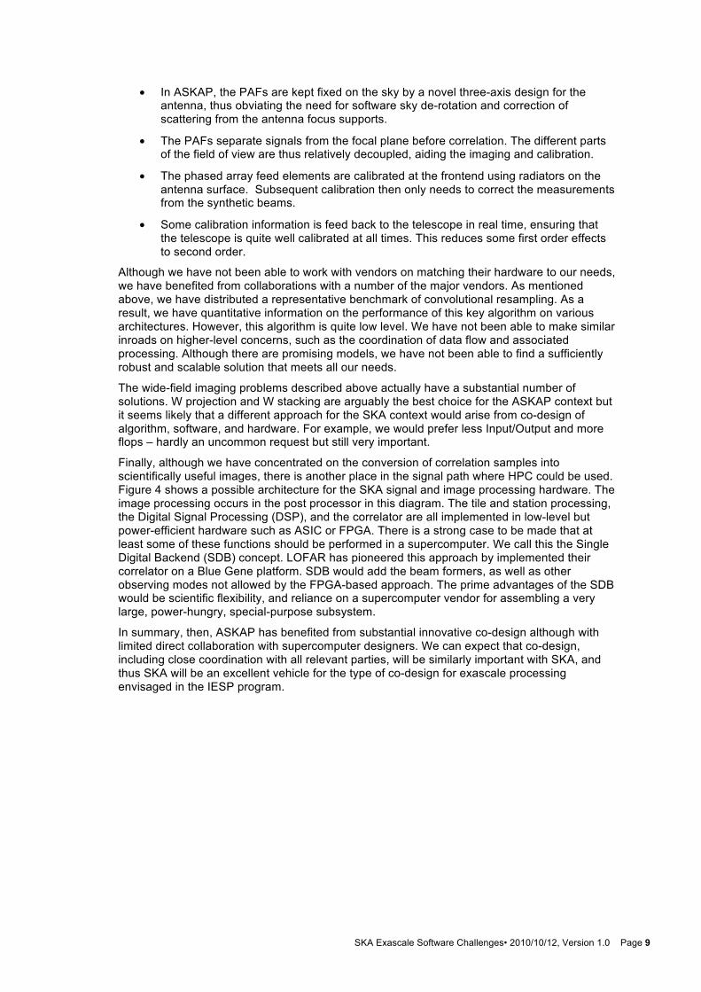
• In ASKAP, the PAFs are kept fixed on the sky by a novel three-axis design for the antenna, thus obviating the need for software sky de-rotation and correction of scattering from the antenna focus supports.
• The PAFs separate signals from the focal plane before correlation. The different parts of the field of view are thus relatively decoupled, aiding the imaging and calibration.
• The phased array feed elements are calibrated at the frontend using radiators on the antenna surface. Subsequent calibration then only needs to correct the measurements from the synthetic beams.
• Some calibration information is feed back to the telescope in real time, ensuring that the telescope is quite well calibrated at all times. This reduces some first order effects to second order.
Although we have not been able to work with vendors on matching their hardware to our needs, we have benefited from collaborations with a number of the major vendors. As mentioned above, we have distributed a representative benchmark of convolutional resampling. As a result, we have quantitative information on the performance of this key algorithm on various architectures. However, this algorithm is quite low level. We have not been able to make similar inroads on higher-level concerns, such as the coordination of data flow and associated processing. Although there are promising models, we have not been able to find a sufficiently robust and scalable solution that meets all our needs.
The wide-field imaging problems described above actually have a substantial number of solutions. W projection and W stacking are arguably the best choice for the ASKAP context but it seems likely that a different approach for the SKA context would arise from co-design of algorithm, software, and hardware. For example, we would prefer less Input/Output and more flops – hardly an uncommon request but still very important.
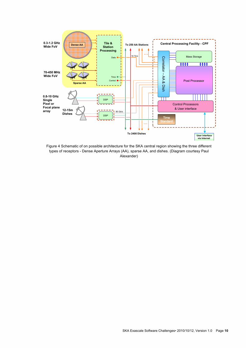
Finally, although we have concentrated on the conversion of correlation samples into scientifically useful images, there is another place in the signal path where HPC could be used. Figure 4 shows a possible architecture for the SKA signal and image processing hardware. The image processing occurs in the post processor in this diagram. The tile and station processing, the Digital Signal Processing (DSP), and the correlator are all implemented in low-level but power-efficient hardware such as ASIC or FPGA. There is a strong case to be made that at least some of these functions should be performed in a supercomputer. We call this the Single Digital Backend (SDB) concept. LOFAR has pioneered this approach by implemented their correlator on a Blue Gene platform. SDB would add the beam formers, as well as other observing modes not allowed by the FPGA-based approach. The prime advantages of the SDB would be scientific flexibility, and reliance on a supercomputer vendor for assembling a very large, power-hungry, special-purpose subsystem.
In summary, then, ASKAP has benefited from substantial innovative co-design although with limited direct collaboration with supercomputer designers. We can expect that co-design, including close coordination with all relevant parties, will be similarly important with SKA, and thus SKA will be an excellent vehicle for the type of co-design for exascale processing envisaged in the IESP program.
SKA Exascale Software Challenges• 2010/10/12, Version 1.0 Page 10
Figure 4 Schematic of on possible architecture for the SKA central region showing the three different
types of receptors - Dense Aperture Arrays (AA), sparse AA, and dishes. (Diagram courtesy Paul Alexander)
SKA Overall SystemSKA Overall System
Dense AA Central Processing Facility - CPF To 250 AA Stations0.3-1.2 GHzWide FoV
Tile &St ti
Mass Storage...
... Corre
16 Tb/sData
Wide FoV StationProcessing
..
..
elator –A
A Post ProcessorTime
Control
70-450 MHzWide FoV
Sparse AA
...
& D
ishPost ProcessorControl
0.8-10 GHzDSP
DSP
12-15m Dishes
80 Gb/s
Control Processors& User interface
Single Pixel or Focal planearray
TimeTimeStandardStandard
DSP
...
Paul AlexanderSKA Data FlowCalim2010
User interfacevia Internet
To 2400 Dishes