sketch package for 6 channel infra-red … _channel.… · anyone up for re-programming the atmel...
TRANSCRIPT
© Les Carpenter_G4CNH 2017 Page 1 of 26 May be copied without consent provided the contents are not used for commercial purposes or financial gain of any kind.
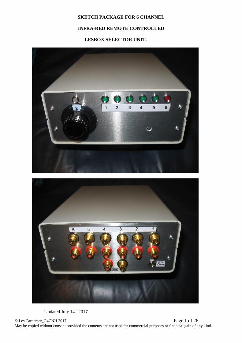
SKETCH PACKAGE FOR 6 CHANNEL
INFRA-RED REMOTE CONTROLLED
LESBOX SELECTOR UNIT.
Updated July 14th 2017
© Les Carpenter_G4CNH 2017 Page 2 of 26 May be copied without consent provided the contents are not used for commercial purposes or financial gain of any kind.
CONTENTS
INTRODUCTION ..................................................................................................................... 3
Scope of this document .............................................................................................................. 3
General Description ................................................................................................................... 3 Technical Description ................................................................................................................ 4
Diode Matrix .............................................................................................................................. 5 Construction Notes..................................................................................................................... 6 Main Signal Board Testing ........................................................................................................ 6 Lower Relay Board Tests........................................................................................................... 7 Upper Relay Board Tests ........................................................................................................... 7
Function Tests: ........................................................................................................................... 9 SPECIAL NOTE:....................................................................................................................... 9 Parts Lists ................................................................................................................................. 10 Case and Signal Board. ............................................................................................................ 10 Note: excluding basic hardware. .............................................................................................. 10
6 channel diode circuit. ............................................................................................................ 12
Receiver Board......................................................................................................................... 13
Diode Boards ........................................................................................................................... 14 LED Board ............................................................................................................................... 14 Relay Board Circuit ................................................................................................................. 15 Drilling – Front Panel .............................................................................................................. 16
Rear Panel ................................................................................................................................ 17 Case Detail and Relay Board Positions ................................................................................... 18 Bottom drilling ......................................................................................................................... 18
Case Fixings ............................................................................................................................. 19 Infra-red control information ................................................................................................... 20
IR Remote Control ................................................................................................................... 21 CD40107 info........................................................................................................................... 22 Relay info ................................................................................................................................. 23
Labels ....................................................................................................................................... 23
Prototype Photographs ............................................................................................................. 24 Alternative layout without diode matrix sub boards. ............................................................... 26
Feel free to build this as you wish, different case, non-isolated grounds thus reducing
the relay requirement by 50% etc.
The enclosed is a record of how the author did the construction and no doubt it could
be simplified if there was some way of re-programming the PIC that comes with the IR
receiver. The requirement for separate latches and large diode matrix array would in
all probability be removed. Anyone up for re-programming the Atmel 89C2051-24PC
micro-controller?
Another similar unit has been designed that sports two selectable outputs, with this
additional facility, a separate headphone amplifier for example, can be selected if
required as well as a main amplifier output.
Les Carpenter
See it in action :- https://www.youtube.com/watch?v=aBD6NTmcy20
© Les Carpenter_G4CNH 2017 Page 3 of 26 May be copied without consent provided the contents are not used for commercial purposes or financial gain of any kind.
INTRODUCTION
Scope of this document
This document describes the 6 Channel infra-red remote controlled LesBox selector and control unit.
In addition to manufacturing drawings, descriptions and parts list, necessary test equipment,
connections and test procedures are described.
General Description
The unit is designed to accept five stereo INPUTS and drive two stereo OUTPUTS via Phono/RCA
sockets. The inputs are 1, 2, 3, 4 and 5, the outputs are 6 (TAPE OUT) and AMPLIFIER OUT.
When each of the channels is selected a Green LED is displayed (Red for channel 6), although simply
numbered 1 to 6, actual channel identification can be provided by a label on the hand held transmitter.
The main amplifier output is permanently connected to the internal audio bus via the motor driven
volume control. The other output (6) acts as a Tape output. To avoid any sound degradation caused by
the Tape output cables, output 6 is kept out of circuit until a Tape Recorder or other device is required
to be connected. The Tape output (6) displays a Red LED when its sockets have been selected to make
contact with the internal audio busses.
Because the infra-red receiver only has momentary outputs that go to logic low (whilst the
corresponding button on the remote transmitter is pressed), it is necessary to use latches to remember
channel selection. Consequently each latch has to be reset when other channels are being selected.
An interlocking feature therefor exists to ensure that any input selected will de-select all other inputs.
However, selecting TAPE OUTPUT (6) will not de-select any of the other inputs.
Thus sending audio out to the Tape sockets requires the source to be selected first and finally the
TAPE OUTPUT. In this way, bus isolation from the TAPE outputs is guaranteed on any source as
selecting them will always de-select TAPE OUTPUT.
In the situation where only one pair of cables connects to a PC soundcard then you may wish to do
input/output selecting at the PC. To achieve this, you will need to connect the PC cables to the TAPE
OUT sockets and do the following.
To send audio to the PC then select the required source and then select TAPE OUT.
To send audio from the PC, select channel button 8 which will clear all other inputs, then select TAPE
OUT (6). Tape Out will thus act as a bi-directional circuit and as there are no other inputs, the signal
will not be degraded by any cables.
The outputs from the audio busses going to the amplifier sockets can be controlled by the infra-red
controller which utilises a motorised ALPS potentiometer. This is controlled by the larger push buttons
on the hand held transmitter, Button 13 lowers the volume and button 14 raises the volume.
The motorised control has a clutch system to prevent damage to the motor from over or under run. The
clutch also allows full manual control of the volume control at any time.
To show direction of control, a dual colour indicating LED is used, Green when lowering the volume
and Red when it is increasing. When no direction control is being applied, the LED will glow Amber
and serves as a power on indicator.
The unit accepts +6V from a regulated power unit, centre pin of the supply connector is positive. At
power up any of the five inputs can be set to be active using a board mounted jumper wire, it is
supplied pre-set with the jumper set to activate channel 1.
It is recommended that a wireless controlled power switch is employed such that all power is removed
from both your amplifier and the remote controlled switch box power supply when not in use.
© Les Carpenter_G4CNH 2017 Page 4 of 26 May be copied without consent provided the contents are not used for commercial purposes or financial gain of any kind.
Technical Description
As previously mentioned, all outputs from the infra-red receiver board are active low and momentary
whilst the respective remote button is pressed.
Each of the main channel selectors (1 to 5) work in similar fashion so the circuit description of
Channel 1 should suffice for the remainder.
On power up, C5 forces the Set/Reset latch (IC1) to the reset condition; the remaining latch circuits
are reset by capacitors C6, 7, C8, C9 and C10. However, the set input on pin 1 can be connected to the
longer time constant circuit D3 and C4 by the jumper wire. Assuming the wire is connected to Set pin
1, this ensures that channel 1 input will be auto selected on power-up because as well as forcing a set
condition on the channel 1 latch; it also forces a reset on the other latches via diodes fitted on the diode
matrix boards 1 to 6. D3 prevents discharge from C4 that could damage the driver of the receiver
board and at the same time ensures that C4 will only have an effect at power-up and will not hinder
further selection of the other sources. D2 ensures the capacitor is discharged at power-down ready for
another reset. Note that only one of the link pins may be jump wired at any one time. They may all be
left disconnected, in which case the capacitors will reset all latches and leave all front panel LED’s
extinguished.
The output low from IC1 pins 2/5, sink the current through RL1, RL2 and R22 to activate the relays
for the channel 1 input sockets. D31 is used as a back stop diode to protect IC1 by clamping its output
to the supply rails should there be any high voltages produced from relay de-activation. Note in this
design that both the inner and outer connections of the RCA inputs is switched, this ensures maximum
protection from hum loops via the outer screens of the connected audio cables. In fact the signal
Grounds never see the Ground circuits of the internal selector box wiring, complete isolation is
assured.
If Channel 2 is selected, the output from the receiver will set IC2 but at the same time, will provide a
reset on the other latches via diodes fitted on the diode matrix boards 1 to 6.
RL3 and RL4 are now energised for the channel 2 sockets.
If channel 3 is selected, the output from the receiver will set IC3 but at the same time, a reset on the
other latches via diodes fitted on the diode matrix boards 1 to 6.
RL5 and RL6 are now energised for the channel 3 sockets.
If Channel 4 is selected, the output from the receiver will set IC4 but at the same time, a reset on the
other latches via diodes fitted on the diode matrix boards 1 to 6.
RL7 and RL8 are now energised for the channel 4 sockets.
If Channel 5 is selected, the output from the receiver will set IC5 but at the same time, a reset on the
other latches via diodes fitted on the diode matrix boards 1 to 6.
RL9 and RL10 are now energised for the channel 5 sockets.
If Channel 6 is selected, the output from the receiver will set IC6 but none of the other channels
selected will be reset.
RL11 and RL12 are now energised for the channel 6 sockets. As previously mentioned, Channel 6 is
reserved as an auxiliary output for such devices as a Tape Deck or feed to a PC soundcard. It will be
reset by any of the other inputs so it must be selected AFTER the required source has already been
selected.
If Channel 8 is selected, the output from the receiver will reset all of the channels via diodes fitted on
the diode matrix boards 1 to 6.
This acts as a ‘Clear All’ and allows channel 6 to be used as an alternative input channel.
© Les Carpenter_G4CNH 2017 Page 5 of 26 May be copied without consent provided the contents are not used for commercial purposes or financial gain of any kind.
The two remaining momentary channels 13 and 14 are arranged to control the volume potentiometer.
Rather than construct an elaborate bridge circuit, it was found that a simple arrangement using R27
and R28 could be used to provide a bi-directional motor supply. The motor is wired such that a low
level on channel 13 causes anti-clockwise rotation to turn down the volume control, the motor current
being supplied by R28. A low level on channel 14 causes clockwise rotation to turn up the volume
control, the motor current being supplied by R27.
Note that all channels are connected to their own grounds when not selected; a small value resistor is
placed in series to protect any input that might otherwise be damaged by a direct short circuit
connection. The inputs, treated in this way, help to combat any cross talk on the audio input bus and as
mentioned, keeping the grounds fully isolated from each other should prevent any multiple hum loops.
Authors findings on use of isolated grounds.
I found it immediately apparent that the sound from each of the sources sounded much ‘cleaner’, the sound
seemed so much better with the loss of background that either my ears filtered out or I had just become used
to thinking that this was the norm. It is only when you get such clear sound, even from the cable TV input
that one appreciates the benefit that isolated grounding has given.
It was a hard decision to make as it doubled the number of relays required but thankfully the type chosen are
relatively cheap. I deem it as one of the most successful experiments I have made and of course cross talk
too is a thing of the past, it was notorious with the stock Yaqin 10T and 100B. Sometimes a bit of DIY can
beat what is available commercially and no doubt a ready to buy remote like this would cost a lot more
dollar than it cost me to build.
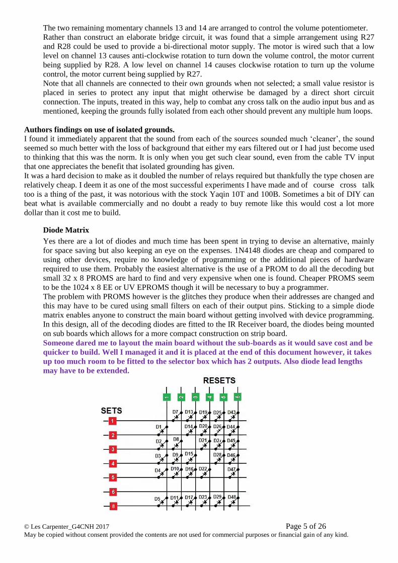
Diode Matrix
Yes there are a lot of diodes and much time has been spent in trying to devise an alternative, mainly
for space saving but also keeping an eye on the expenses. 1N4148 diodes are cheap and compared to
using other devices, require no knowledge of programming or the additional pieces of hardware
required to use them. Probably the easiest alternative is the use of a PROM to do all the decoding but
small 32 x 8 PROMS are hard to find and very expensive when one is found. Cheaper PROMS seem
to be the 1024 x 8 EE or UV EPROMS though it will be necessary to buy a programmer.
The problem with PROMS however is the glitches they produce when their addresses are changed and
this may have to be cured using small filters on each of their output pins. Sticking to a simple diode
matrix enables anyone to construct the main board without getting involved with device programming.
In this design, all of the decoding diodes are fitted to the IR Receiver board, the diodes being mounted
on sub boards which allows for a more compact construction on strip board.
Someone dared me to layout the main board without the sub-boards as it would save cost and be
quicker to build. Well I managed it and it is placed at the end of this document however, it takes
up too much room to be fitted to the selector box which has 2 outputs. Also diode lead lengths
may have to be extended.
© Les Carpenter_G4CNH 2017 Page 6 of 26 May be copied without consent provided the contents are not used for commercial purposes or financial gain of any kind.
Construction Notes
Fit main receiver board to the cabinet base, although it will fit the aluminium extrusions (like the
relay boards), it was decided to fit to the cabinet base as shown. It allowed line up of the IR
receiver IC1 to the front panel and also made it more convenient to wire to the motor. With regard to
the IR receiver, placing a small amount of grease to its front end helps locate a good position to drill
its sensor hole in the front panel, which may vary in height depending on the mounting pillars you
use.
Assemble front panel without the LED’s fitted in their holders and apply label. The bi-coloured
LED and motor supply can now be wired. I found the screw-in LED holder to be incapable of
handling a tri-wired LED so fitted Red, Black and Green wires to the LED. The solder points and
bare wires were covered with small bore heat shrink tubing. These were then covered with a short
section of larger heat shrink and finally a piece of larger diameter to fit over the body of the holder
and assist in retaining the LED in its holder.
Carry out tests on the main signal board as detailed below.
Main Signal Board Testing
Using a remote 6V power supply, connect Positive to Pin 1 and 0V to Pin 2.
1. Check that the motor direction/supply indicator LED is showing Amber.
2. Press button 13 on the Remote Transmitter and check that the volume control turns counter-
clockwise and the LED now shows a Green colour. This should turn back to Amber when the
button is released.
3. Press button 14 on the Remote Transmitter and check that the volume control turns clockwise
and the LED now shows a Red colour. This should turn back to Amber when the button is
released.
4. Using a Multimeter connected to 0V and the following Pins, check that the voltages are present
according to the table. Note that the voltages are approximate.
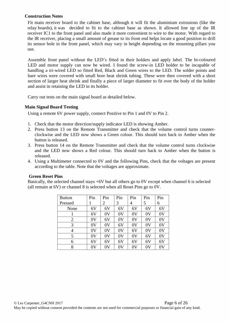
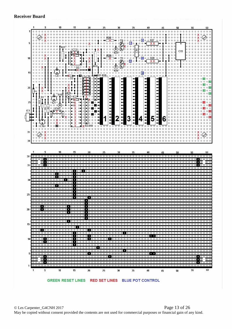
Green Reset Pins
Basically, the selected channel stays +6V but all others go to 0V except when channel 6 is selected
(all remain at 6V) or channel 8 is selected when all Reset Pins go to 0V.
Button
Pressed
Pin
1
Pin
2
Pin
3
Pin
4
Pin
5
Pin
6
None 6V 6V 6V 6V 6V 6V
1 6V 0V 0V 0V 0V 0V
2 0V 6V 0V 0V 0V 0V
3 0V 0V 6V 0V 0V 0V
4 0V 0V 0V 6V 0V 0V
5 0V 0V 0V 0V 6V 0V
6 6V 6V 6V 6V 6V 6V
8 0V 0V 0V 0V 0V 0V
© Les Carpenter_G4CNH 2017 Page 7 of 26 May be copied without consent provided the contents are not used for commercial purposes or financial gain of any kind.
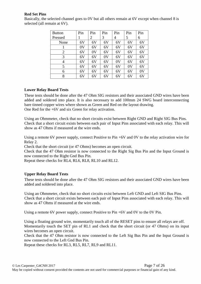
Red Set Pins
Basically, the selected channel goes to 0V but all others remain at 6V except when channel 8 is
selected (all remain at 6V).
Button
Pressed
Pin
1
Pin
2
Pin
3
Pin
4
Pin
5
Pin
6
None 6V 6V 6V 6V 6V 6V
1 0V 6V 6V 6V 6V 6V
2 6V 0V 6V 6V 6V 6V
3 6V 6V 0V 6V 6V 6V
4 6V 6V 6V 0V 6V 6V
5 6V 6V 6V 6V 0V 6V
6 6V 6V 6V 6V 6V 0V
8 6V 6V 6V 6V 6V 6V
Lower Relay Board Tests
These tests should be done after the 47 Ohm SIG resistors and their associated GND wires have been
added and soldered into place. It is also necessary to add 100mm 24 SWG board interconnecting
bare tinned copper wires where shown as Green and Red on the layout drawing.
One Red for the +6V and six Green for relay activation.
Using an Ohmmeter, check that no short circuits exist between Right GND and Right SIG Bus Pins.
Check that a short circuit exists between each pair of Input Pins associated with each relay. This will
show as 47 Ohms if measured at the wire ends.
Using a remote 6V power supply, connect Positive to Pin +6V and 0V to the relay activation wire for
Relay 2.
Check that the short circuit (or 47 Ohms) becomes an open circuit.
Check that the 47 Ohm resistor is now connected to the Right Sig Bus Pin and the Input Ground is
now connected to the Right Gnd Bus Pin.
Repeat these checks for RL4, RL6, RL8, RL10 and RL12.
Upper Relay Board Tests
These tests should be done after the 47 Ohm SIG resistors and their associated GND wires have been
added and soldered into place.
Using an Ohmmeter, check that no short circuits exist between Left GND and Left SIG Bus Pins.
Check that a short circuit exists between each pair of Input Pins associated with each relay. This will
show as 47 Ohms if measured at the wire ends.
Using a remote 6V power supply, connect Positive to Pin +6V and 0V to the 0V Pin.
Using a floating ground wire, momentarily touch all of the RESET pins to ensure all relays are off.
Momentarily touch the SET pin of RL1 and check that the short circuit (or 47 Ohms) on its input
wires becomes an open circuit.
Check that the 47 Ohm resistor is now connected to the Left Sig Bus Pin and the Input Ground is
now connected to the Left Gnd Bus Pin.
Repeat these checks for RL3, RL5, RL7, RL9 and RL11.
© Les Carpenter_G4CNH 2017 Page 8 of 26 May be copied without consent provided the contents are not used for commercial purposes or financial gain of any kind.
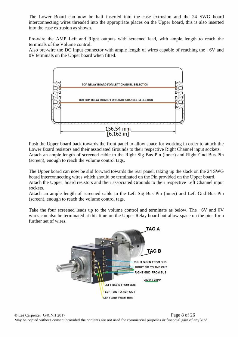
The Lower Board can now be half inserted into the case extrusion and the 24 SWG board
interconnecting wires threaded into the appropriate places on the Upper board, this is also inserted
into the case extrusion as shown.
Pre-wire the AMP Left and Right outputs with screened lead, with ample length to reach the
terminals of the Volume control.
Also pre-wire the DC Input connector with ample length of wires capable of reaching the +6V and
0V terminals on the Upper board when fitted.
Push the Upper board back towards the front panel to allow space for working in order to attach the
Lower Board resistors and their associated Grounds to their respective Right Channel input sockets.
Attach an ample length of screened cable to the Right Sig Bus Pin (inner) and Right Gnd Bus Pin
(screen), enough to reach the volume control tags.
The Upper board can now be slid forward towards the rear panel, taking up the slack on the 24 SWG
board interconnecting wires which should be terminated on the Pin provided on the Upper board.
Attach the Upper board resistors and their associated Grounds to their respective Left Channel input
sockets.
Attach an ample length of screened cable to the Left Sig Bus Pin (inner) and Left Gnd Bus Pin
(screen), enough to reach the volume control tags.
Take the four screened leads up to the volume control and terminate as below. The +6V and 0V
wires can also be terminated at this time on the Upper Relay board but allow space on the pins for a
further set of wires.
© Les Carpenter_G4CNH 2017 Page 9 of 26 May be copied without consent provided the contents are not used for commercial purposes or financial gain of any kind.
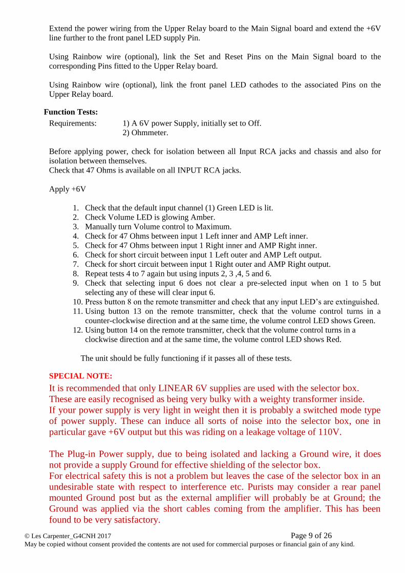
Extend the power wiring from the Upper Relay board to the Main Signal board and extend the +6V
line further to the front panel LED supply Pin.
Using Rainbow wire (optional), link the Set and Reset Pins on the Main Signal board to the
corresponding Pins fitted to the Upper Relay board.
Using Rainbow wire (optional), link the front panel LED cathodes to the associated Pins on the
Upper Relay board.
Function Tests:
Requirements: 1) A 6V power Supply, initially set to Off.
2) Ohmmeter.
Before applying power, check for isolation between all Input RCA jacks and chassis and also for
isolation between themselves.
Check that 47 Ohms is available on all INPUT RCA jacks.
Apply +6V
1. Check that the default input channel (1) Green LED is lit.
2. Check Volume LED is glowing Amber.
3. Manually turn Volume control to Maximum.
4. Check for 47 Ohms between input 1 Left inner and AMP Left inner.
5. Check for 47 Ohms between input 1 Right inner and AMP Right inner.
6. Check for short circuit between input 1 Left outer and AMP Left output.
7. Check for short circuit between input 1 Right outer and AMP Right output.
8. Repeat tests 4 to 7 again but using inputs 2, 3 ,4, 5 and 6.
9. Check that selecting input 6 does not clear a pre-selected input when on 1 to 5 but
selecting any of these will clear input 6.
10. Press button 8 on the remote transmitter and check that any input LED’s are extinguished.
11. Using button 13 on the remote transmitter, check that the volume control turns in a
counter-clockwise direction and at the same time, the volume control LED shows Green.
12. Using button 14 on the remote transmitter, check that the volume control turns in a
clockwise direction and at the same time, the volume control LED shows Red.
The unit should be fully functioning if it passes all of these tests.
SPECIAL NOTE:
It is recommended that only LINEAR 6V supplies are used with the selector box.
These are easily recognised as being very bulky with a weighty transformer inside.
If your power supply is very light in weight then it is probably a switched mode type
of power supply. These can induce all sorts of noise into the selector box, one in
particular gave +6V output but this was riding on a leakage voltage of 110V.
The Plug-in Power supply, due to being isolated and lacking a Ground wire, it does
not provide a supply Ground for effective shielding of the selector box.
For electrical safety this is not a problem but leaves the case of the selector box in an
undesirable state with respect to interference etc. Purists may consider a rear panel
mounted Ground post but as the external amplifier will probably be at Ground; the
Ground was applied via the short cables coming from the amplifier. This has been
found to be very satisfactory.
© Les Carpenter_G4CNH 2017 Page 10 of 26 May be copied without consent provided the contents are not used for commercial purposes or financial gain of any kind.
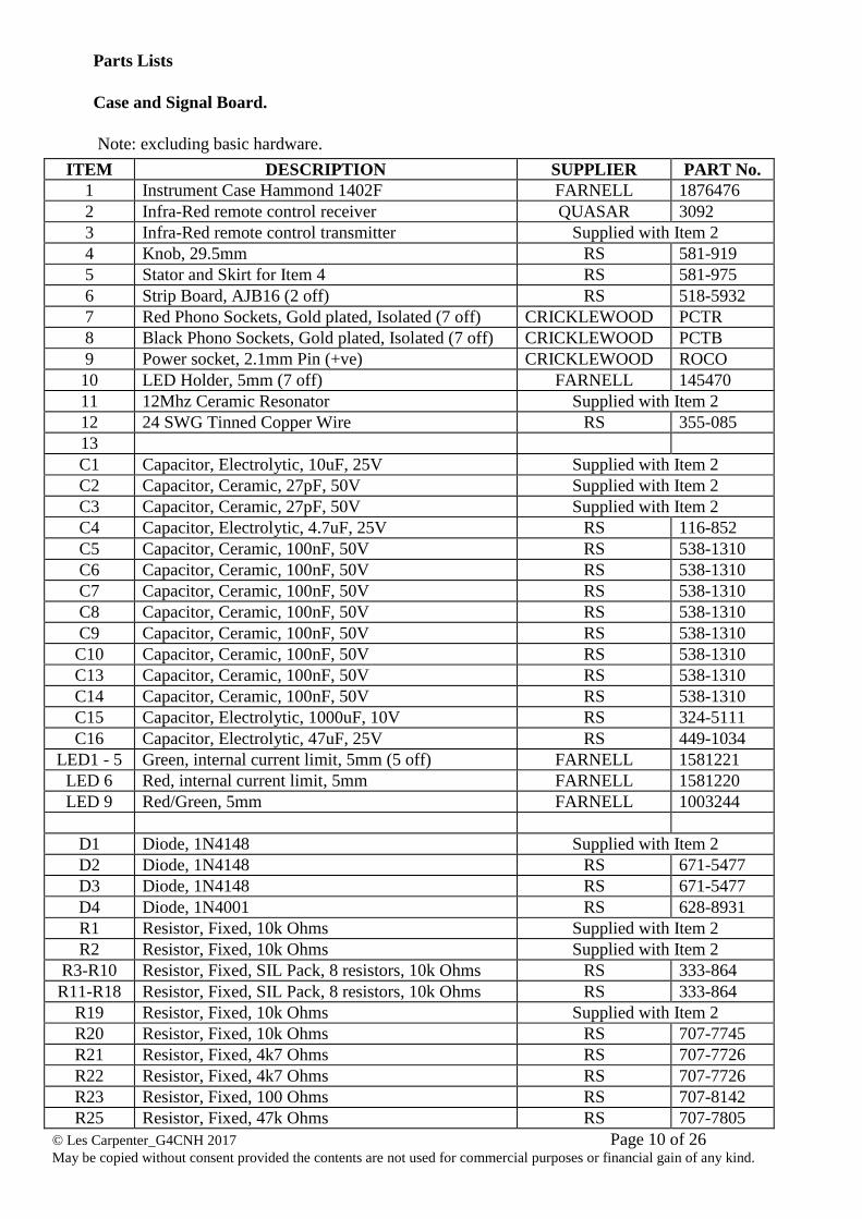
Parts Lists
Case and Signal Board.
Note: excluding basic hardware.
ITEM DESCRIPTION SUPPLIER PART No.
1 Instrument Case Hammond 1402F FARNELL 1876476
2 Infra-Red remote control receiver QUASAR 3092
3 Infra-Red remote control transmitter Supplied with Item 2
4 Knob, 29.5mm RS 581-919
5 Stator and Skirt for Item 4 RS 581-975
6 Strip Board, AJB16 (2 off) RS 518-5932
7 Red Phono Sockets, Gold plated, Isolated (7 off) CRICKLEWOOD PCTR
8 Black Phono Sockets, Gold plated, Isolated (7 off) CRICKLEWOOD PCTB
9 Power socket, 2.1mm Pin (+ve) CRICKLEWOOD ROCO
10 LED Holder, 5mm (7 off) FARNELL 145470
11 12Mhz Ceramic Resonator Supplied with Item 2
12 24 SWG Tinned Copper Wire RS 355-085
13
C1 Capacitor, Electrolytic, 10uF, 25V Supplied with Item 2
C2 Capacitor, Ceramic, 27pF, 50V Supplied with Item 2
C3 Capacitor, Ceramic, 27pF, 50V Supplied with Item 2
C4 Capacitor, Electrolytic, 4.7uF, 25V RS 116-852
C5 Capacitor, Ceramic, 100nF, 50V RS 538-1310
C6 Capacitor, Ceramic, 100nF, 50V RS 538-1310
C7 Capacitor, Ceramic, 100nF, 50V RS 538-1310
C8 Capacitor, Ceramic, 100nF, 50V RS 538-1310
C9 Capacitor, Ceramic, 100nF, 50V RS 538-1310
C10 Capacitor, Ceramic, 100nF, 50V RS 538-1310
C13 Capacitor, Ceramic, 100nF, 50V RS 538-1310
C14 Capacitor, Ceramic, 100nF, 50V RS 538-1310
C15 Capacitor, Electrolytic, 1000uF, 10V RS 324-5111
C16 Capacitor, Electrolytic, 47uF, 25V RS 449-1034
LED1 - 5 Green, internal current limit, 5mm (5 off) FARNELL 1581221
LED 6 Red, internal current limit, 5mm FARNELL 1581220
LED 9 Red/Green, 5mm FARNELL 1003244
D1 Diode, 1N4148 Supplied with Item 2
D2 Diode, 1N4148 RS 671-5477
D3 Diode, 1N4148 RS 671-5477
D4 Diode, 1N4001 RS 628-8931
R1 Resistor, Fixed, 10k Ohms Supplied with Item 2
R2 Resistor, Fixed, 10k Ohms Supplied with Item 2
R3-R10 Resistor, Fixed, SIL Pack, 8 resistors, 10k Ohms RS 333-864
R11-R18 Resistor, Fixed, SIL Pack, 8 resistors, 10k Ohms RS 333-864
R19 Resistor, Fixed, 10k Ohms Supplied with Item 2
R20 Resistor, Fixed, 10k Ohms RS 707-7745
R21 Resistor, Fixed, 4k7 Ohms RS 707-7726
R22 Resistor, Fixed, 4k7 Ohms RS 707-7726
R23 Resistor, Fixed, 100 Ohms RS 707-8142
R25 Resistor, Fixed, 47k Ohms RS 707-7805
© Les Carpenter_G4CNH 2017 Page 11 of 26 May be copied without consent provided the contents are not used for commercial purposes or financial gain of any kind.
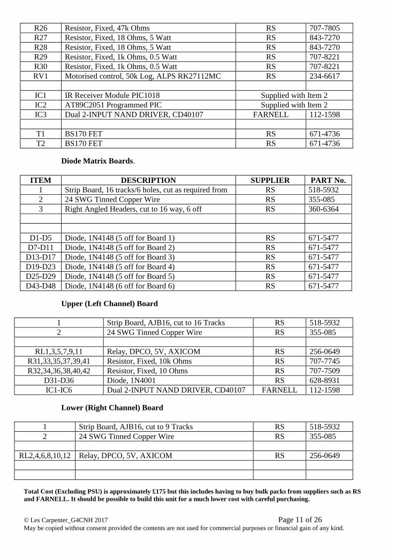
R26 Resistor, Fixed, 47k Ohms RS 707-7805
R27 Resistor, Fixed, 18 Ohms, 5 Watt RS 843-7270
R28 Resistor, Fixed, 18 Ohms, 5 Watt RS 843-7270
R29 Resistor, Fixed, 1k Ohms, 0.5 Watt RS 707-8221
R30 Resistor, Fixed, 1k Ohms, 0.5 Watt RS 707-8221
RV1 Motorised control, 50k Log, ALPS RK27112MC RS 234-6617
IC1 IR Receiver Module PIC1018 Supplied with Item 2
IC2 AT89C2051 Programmed PIC Supplied with Item 2
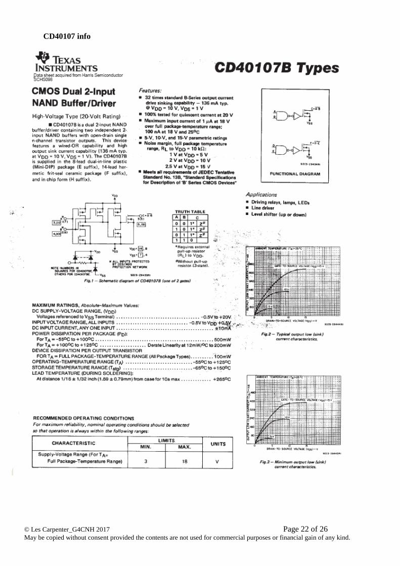
IC3 Dual 2-INPUT NAND DRIVER, CD40107 FARNELL 112-1598
T1 BS170 FET RS 671-4736
T2 BS170 FET RS 671-4736
Diode Matrix Boards.
ITEM DESCRIPTION SUPPLIER PART No.
1 Strip Board, 16 tracks/6 holes, cut as required from RS 518-5932
2 24 SWG Tinned Copper Wire RS 355-085
3 Right Angled Headers, cut to 16 way, 6 off RS 360-6364
D1-D5 Diode, 1N4148 (5 off for Board 1) RS 671-5477
D7-D11 Diode, 1N4148 (5 off for Board 2) RS 671-5477
D13-D17 Diode, 1N4148 (5 off for Board 3) RS 671-5477
D19-D23 Diode, 1N4148 (5 off for Board 4) RS 671-5477
D25-D29 Diode, 1N4148 (5 off for Board 5) RS 671-5477
D43-D48 Diode, 1N4148 (6 off for Board 6) RS 671-5477
Upper (Left Channel) Board
1 Strip Board, AJB16, cut to 16 Tracks RS 518-5932
2 24 SWG Tinned Copper Wire RS 355-085
RL1,3,5,7,9,11 Relay, DPCO, 5V, AXICOM RS 256-0649
R31,33,35,37,39,41 Resistor, Fixed, 10k Ohms RS 707-7745
R32,34,36,38,40,42 Resistor, Fixed, 10 Ohms RS 707-7509
D31-D36 Diode, 1N4001 RS 628-8931
IC1-IC6 Dual 2-INPUT NAND DRIVER, CD40107 FARNELL 112-1598
Lower (Right Channel) Board
1 Strip Board, AJB16, cut to 9 Tracks RS 518-5932
2 24 SWG Tinned Copper Wire RS 355-085
RL2,4,6,8,10,12 Relay, DPCO, 5V, AXICOM RS 256-0649
Total Cost (Excluding PSU) is approximately £175 but this includes having to buy bulk packs from suppliers such as RS
and FARNELL. It should be possible to build this unit for a much lower cost with careful purchasing.
© Les Carpenter_G4CNH 2017 Page 12 of 26 May be copied without consent provided the contents are not used for commercial purposes or financial gain of any kind.
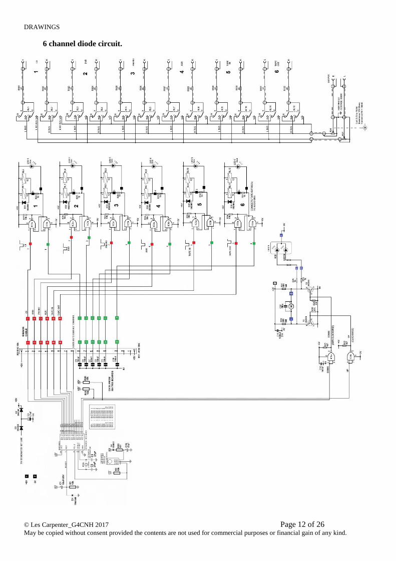
DRAWINGS
6 channel diode circuit.
© Les Carpenter_G4CNH 2017 Page 13 of 26 May be copied without consent provided the contents are not used for commercial purposes or financial gain of any kind.
Receiver Board
© Les Carpenter_G4CNH 2017 Page 14 of 26 May be copied without consent provided the contents are not used for commercial purposes or financial gain of any kind.
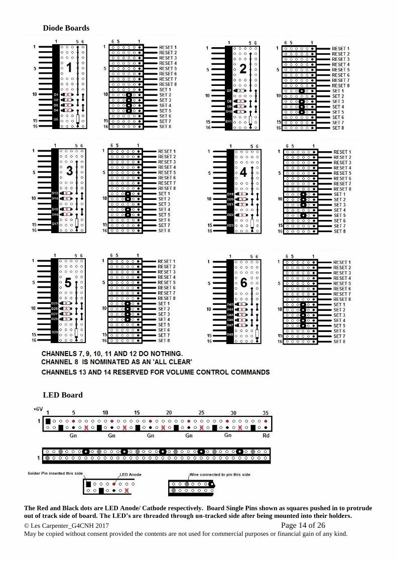
Diode Boards
LED Board
The Red and Black dots are LED Anode/ Cathode respectively. Board Single Pins shown as squares pushed in to protrude
out of track side of board. The LED’s are threaded through un-tracked side after being mounted into their holders.
© Les Carpenter_G4CNH 2017 Page 15 of 26 May be copied without consent provided the contents are not used for commercial purposes or financial gain of any kind.
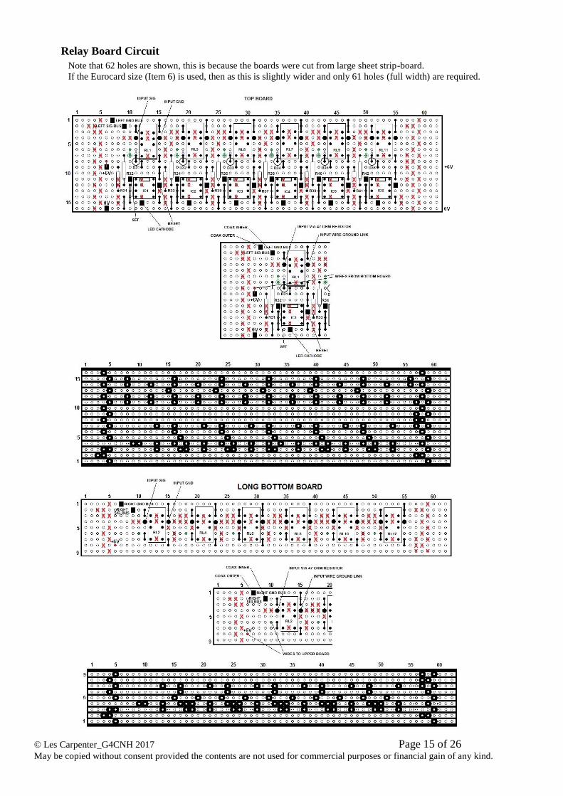
Relay Board Circuit
Note that 62 holes are shown, this is because the boards were cut from large sheet strip-board.
If the Eurocard size (Item 6) is used, then as this is slightly wider and only 61 holes (full width) are required.
© Les Carpenter_G4CNH 2017 Page 16 of 26 May be copied without consent provided the contents are not used for commercial purposes or financial gain of any kind.
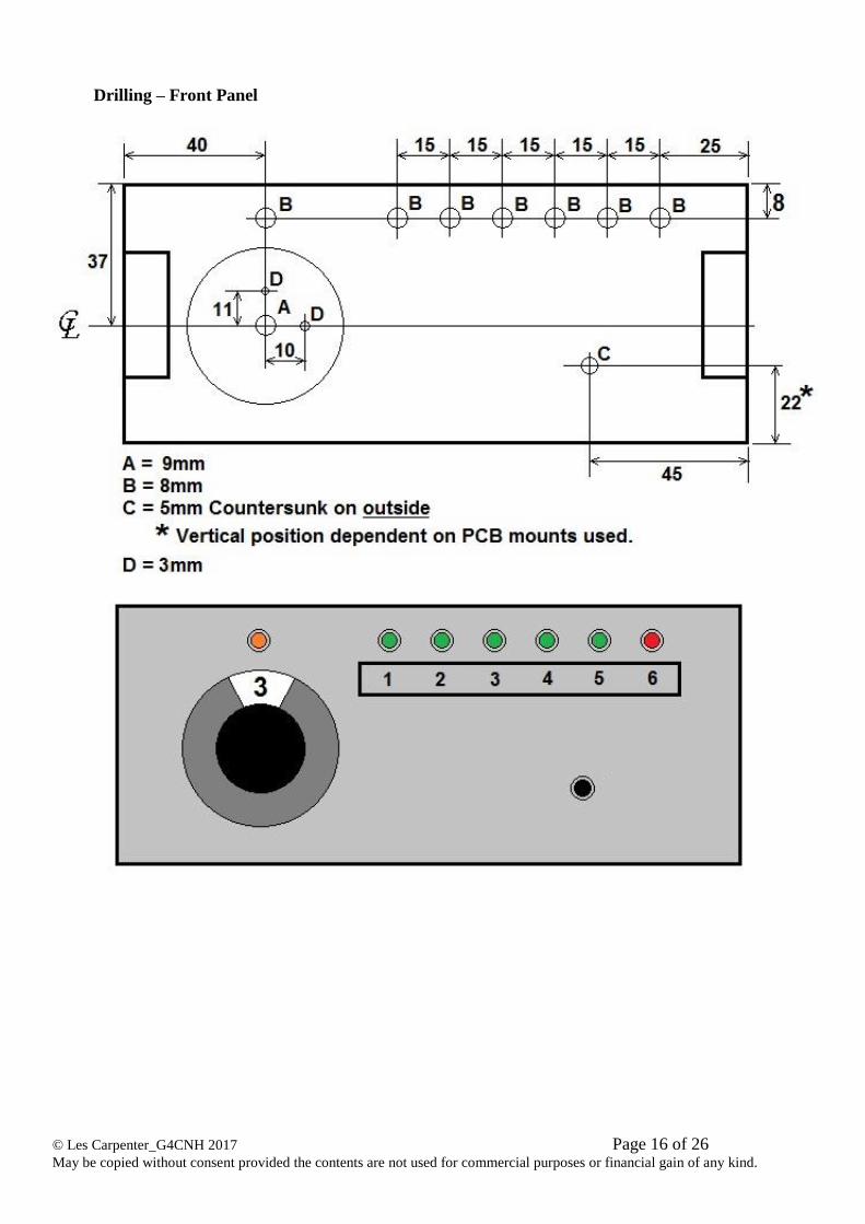
Drilling – Front Panel
© Les Carpenter_G4CNH 2017 Page 17 of 26 May be copied without consent provided the contents are not used for commercial purposes or financial gain of any kind.
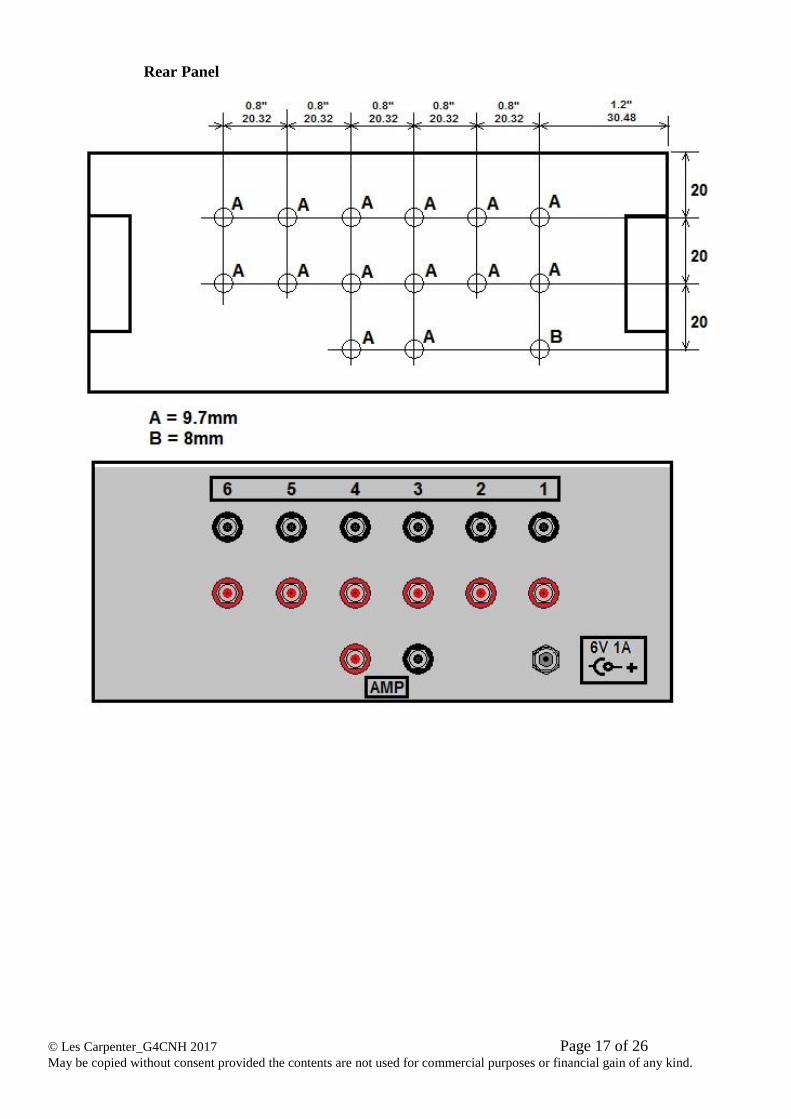
Rear Panel
© Les Carpenter_G4CNH 2017 Page 18 of 26 May be copied without consent provided the contents are not used for commercial purposes or financial gain of any kind.
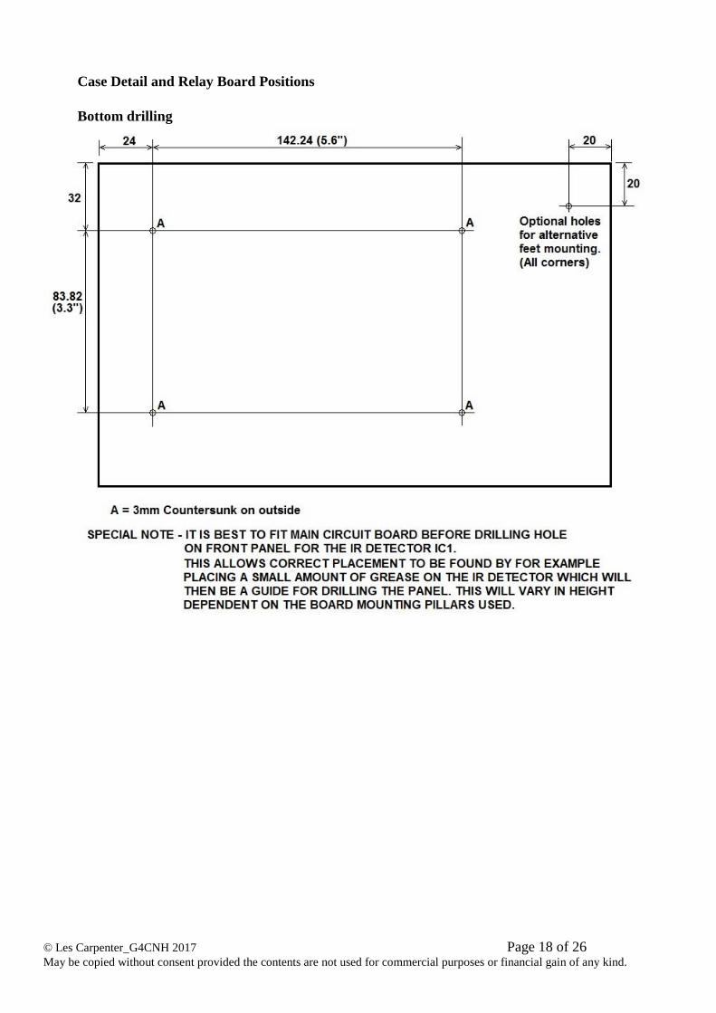
Case Detail and Relay Board Positions
Bottom drilling
© Les Carpenter_G4CNH 2017 Page 19 of 26 May be copied without consent provided the contents are not used for commercial purposes or financial gain of any kind.
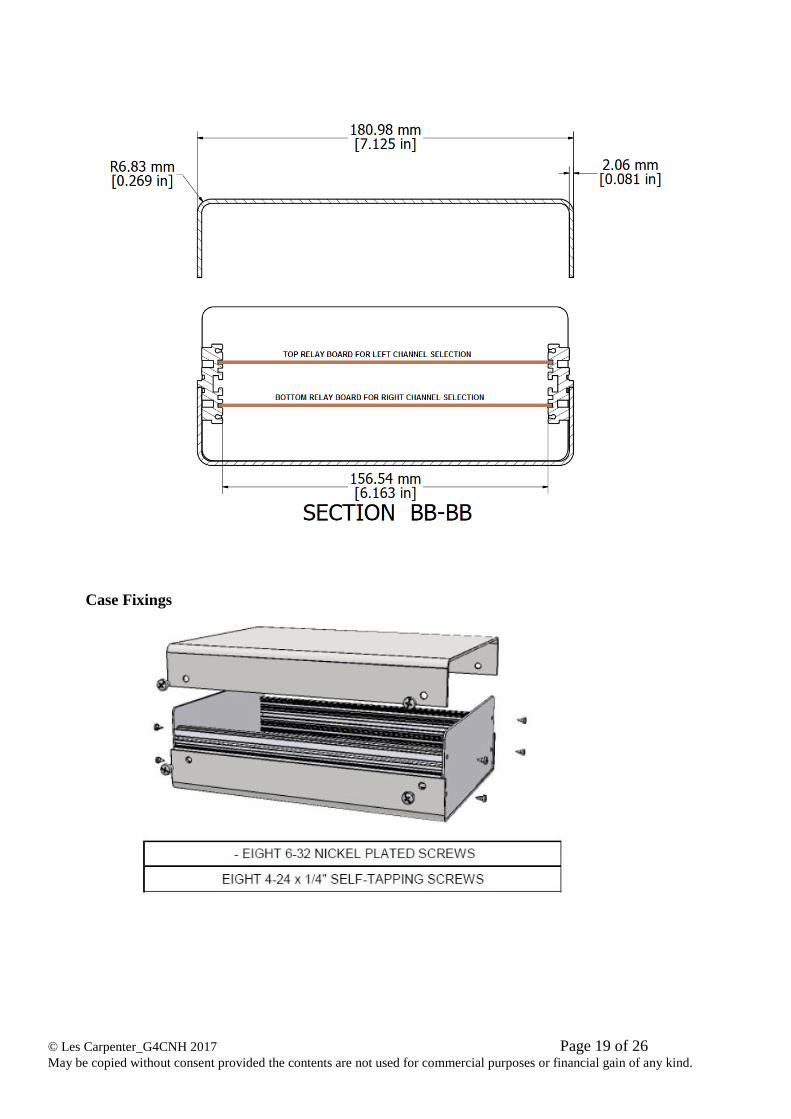
Case Fixings
© Les Carpenter_G4CNH 2017 Page 20 of 26 May be copied without consent provided the contents are not used for commercial purposes or financial gain of any kind.
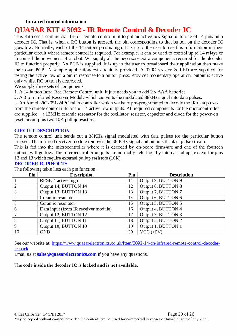
Infra-red control information
QUASAR KIT # 3092 - IR Remote Control & Decoder IC This Kit uses a commercial 14-pin remote control unit to put an active low signal onto one of 14 pins on a
decoder IC. That is, when a RC button is pressed, the pin corresponding to that button on the decoder IC
goes low. Normally, each of the 14 output pins is high. It is up to the user to use this information in their
particular circuit where remote control is required. For example, it can be used to control up to 14 relays or
to control the movement of a robot. We supply all the necessary extra components required for the decoder
IC to function properly. No PCB is supplied. It is up to the user to breadboard their application then make
their own PCB. A sample application/test circuit is provided. A 330resistor & LED are supplied for
testing the active low on a pin in response to a button press. Provides momentary operation; output is active
only whilst RC button is depressed.
We supply three sets of components:
1. A 14 button Infra-Red Remote Control unit. It just needs you to add 2 x AAA batteries.
2. A 3-pin Infrared Receiver Module which converts the modulated 38kHz signal into data pulses.
3. An Atmel 89C2051-24PC microcontroller which we have pre-programmed to decode the IR data pulses
from the remote control into one of 14 active low outputs. All required components for the microcontroller
are supplied – a 12MHz ceramic resonator for the oscillator, resistor, capacitor and diode for the power-on
reset circuit plus two 10K pullup resistors.
CIRCUIT DESCRIPTION
The remote control unit sends out a 38KHz signal modulated with data pulses for the particular button
pressed. The infrared receiver module removes the 38 KHz signal and outputs the data pulse stream.
This is fed into the microcontroller where it is decoded by on-board firmware and one of the fourteen
outputs will go low. The microcontroller outputs are normally held high by internal pullups except for pins
12 and 13 which require external pullup resistors (10K).
DECODER IC PINOUTS
The following table lists each pin function.
Pin Description Pin Description
1 RESET, active high 11 Output 9, BUTTON 9
2 Output 14, BUTTON 14 12 Output 8, BUTTON 8
3 Output 13, BUTTON 13 13 Output 7, BUTTON 7
4 Ceramic resonator 14 Output 6, BUTTON 6
5 Ceramic resonator 15 Output 5, BUTTON 5
6 Data input (from IR receiver module) 16 Output 4, BUTTON 4
7 Output 12, BUTTON 12 17 Output 3, BUTTON 3
8 Output 11, BUTTON 11 18 Output 2, BUTTON 2
9 Output 10, BUTTON 10 19 Output 1, BUTTON 1
10 GND 20 VCC (+5V)
See our website at: https://www.quasarelectronics.co.uk/Item/3092-14-ch-infrared-remote-control-decoder-
ic-pack
Email us at [email protected] if you have any questions.
The code inside the decoder IC is locked and is not available.
© Les Carpenter_G4CNH 2017 Page 21 of 26 May be copied without consent provided the contents are not used for commercial purposes or financial gain of any kind.
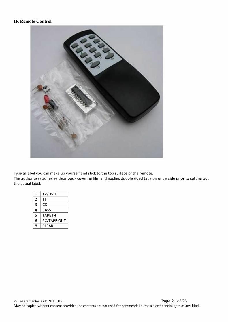
IR Remote Control
Typical label you can make up yourself and stick to the top surface of the remote. The author uses adhesive clear book covering film and applies double sided tape on underside prior to cutting out the actual label.
1 TV/DVD
2 TT
3 CD
4 CASS
5 TAPE IN
6 PC/TAPE OUT
8 CLEAR
© Les Carpenter_G4CNH 2017 Page 22 of 26 May be copied without consent provided the contents are not used for commercial purposes or financial gain of any kind.
CD40107 info
© Les Carpenter_G4CNH 2017 Page 23 of 26 May be copied without consent provided the contents are not used for commercial purposes or financial gain of any kind.
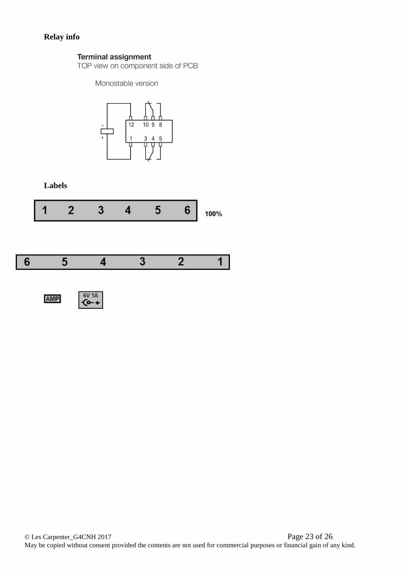
Relay info
Labels
© Les Carpenter_G4CNH 2017 Page 24 of 26 May be copied without consent provided the contents are not used for commercial purposes or financial gain of any kind.
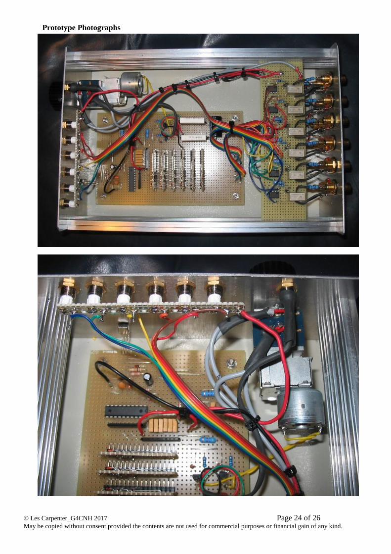
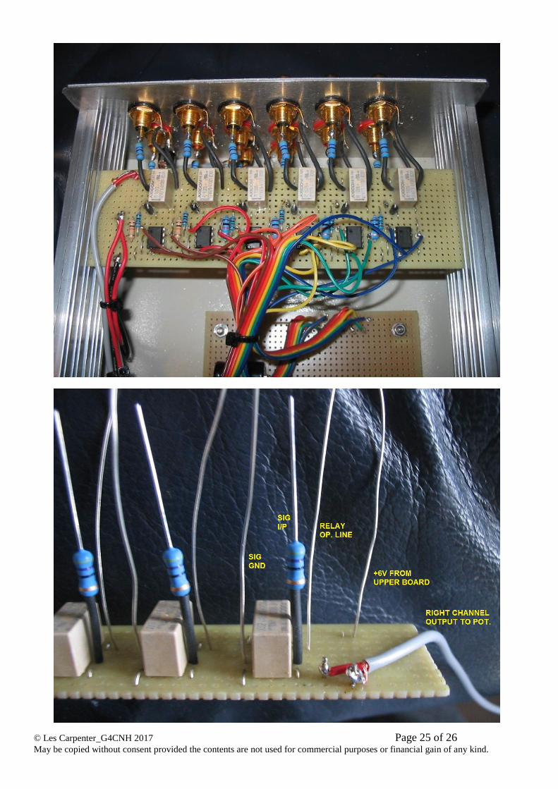
Prototype Photographs
© Les Carpenter_G4CNH 2017 Page 25 of 26 May be copied without consent provided the contents are not used for commercial purposes or financial gain of any kind.
© Les Carpenter_G4CNH 2017 Page 26 of 26 May be copied without consent provided the contents are not used for commercial purposes or financial gain of any kind.
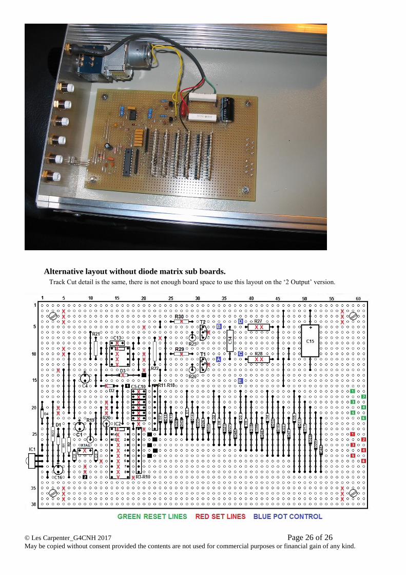
Alternative layout without diode matrix sub boards.
Track Cut detail is the same, there is not enough board space to use this layout on the ‘2 Output’ version.