sketch-to-design: context-based part assembly - … · sketch-to-design: context-based part...
TRANSCRIPT

Volume xx (200y), Number z, pp. 1–10
Sketch-to-Design: Context-based Part Assembly
Xiaohua Xie Kai Xu Niloy J. Mitra Daniel Cohen-Or Baoquan Chen
AbstractDesigning 3D objects from scratch is difficult, especially when the user intent is fuzzy without a clear target form.In the spirit of modeling-by-example, we facilitate design by providing reference and inspiration from existingmodel contexts. We rethink model design as navigating through different possible combinations of part assembliesbased on a large collection of pre-segmented 3D models. We propose an interactive sketch-to-design system, wherethe user sketches prominent features of parts to combine. The sketched strokes are analyzed individually and incontext with the other parts to generate relevant shape suggestions via a design gallery interface. As the sessionprogresses and more parts get selected, contextual cues becomes increasingly dominant and the system quicklyconverges to a final design. As a key enabler, we use pre-learned part-based contextual information to allowthe user to quickly explore different combinations of parts. Our experiments demonstrate the effectiveness of ourapproach for efficiently designing new variations from existing shapes.
1. Introduction
Conceiving shapes from scratch is difficult since earlyconcepts are often fuzzy, ambiguous, and not fullyformed [PKM∗11]. In the early design stages, artists typi-cally explore multiple conceptual options, without prescrib-ing their details. For examples, artists prefer to start withrough sketches, which they progressively over-sketch toeventually converge to a conceptual shape. With a similarmotivation, the recent ShadowDraw system [LZC11] usesa data-driven approach to guide the artists to create betterand well-proportioned sketches. The system, however, doesnot immediately generalize to 3D since the evolving con-ceptual shape cannot be observed or edited from multipleview directions. We introduce a sketch-to-design interactivesystem that instantly converts user sketches to part-based 3Dgeometry, thus retaining the fluidity of the sketching process,while allowing easy 3D model creation.
A successful 3D modeling system should be simple, in-teractive, intuitive to use, and provide multiple design op-tions for different user preferences. In our system, model-ing amounts to navigating a space of mix-and-match mod-els, with the user sketches and context information drivingthe navigation. The user simply sketches prominent featuresand desired shapes of parts, while the system computation-ally retrieves the compatible parts and handles low-level op-erations to assemble and warp the parts together. As the userprogressively explores and selects model parts, fewer modelparts with compatible context clues are left to choose from,thus narrowing down design possibilities. As an analogy,
think of autocomplete option in textual search engines —as the design session progresses, modeling speed increaseswith fewer part options to select from (see Figure 1).
Advances in consistent decomposition of models intoparts (e.g., [KHS10, HKG11, SvKK∗11]) motivate partreuse for model creation. We make use of relative place-ment and context information across parts in large collec-tions of semantically segmented parts to allow the user tointuitively select, position, and glue parts to produce novelmodels. Specifically, we analyze a large set of segmentedmodels to learn their contextual relations (e.g., part pairs incontacts, in symmetry, or in similarity of geometry proper-ties) and use the relations for smart design exploration. Thus,we bypass the difficult task of understanding semantics ofthe parts and their inter-relations.
Inspired by ShadowDraw [LZC11], we present an inter-active system where the user roughly sketches parts over acanvas that displays the current 3D model in the background.We continuously analyze the drawing strokes and their con-text to suggest relevant part combinations to the user via adynamic gallery, with contextual clues becoming increasingdominant in the later stages of the session. At any stage, theuser sketches a part-profile in 2D, while the system suggestsmultiple part possibilities using their original context. Theuser selects one such possibility, the part adapts to the de-sign, and the session proceeds (see supplementary video).Note that the user can change viewpoint at any time.
Generally, sketch-based retrieval of parts is difficult. Sinceparts display less variations compared to whole shapes the
submitted to COMPUTER GRAPHICS Forum (12/2012).
arX
iv:1
212.
4490
v1 [
cs.G
R]
18
Dec
201
2
2 Xie et al. / Sketch-to-Design
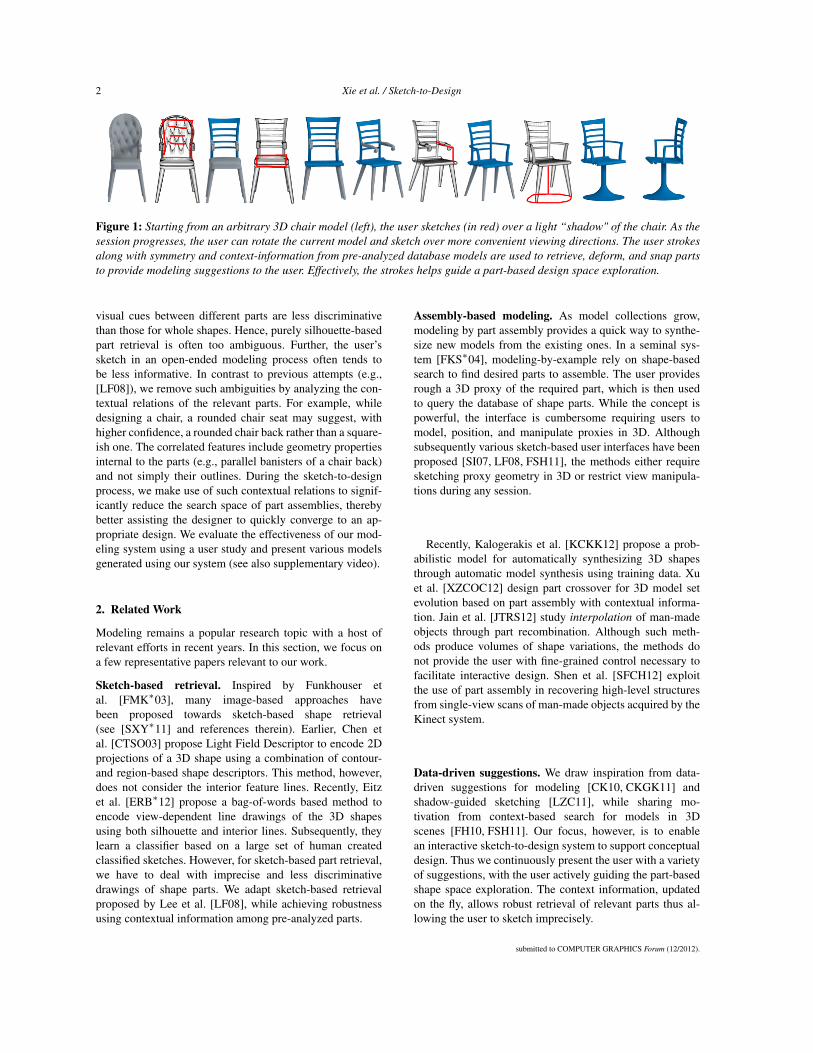
Figure 1: Starting from an arbitrary 3D chair model (left), the user sketches (in red) over a light “shadow" of the chair. As thesession progresses, the user can rotate the current model and sketch over more convenient viewing directions. The user strokesalong with symmetry and context-information from pre-analyzed database models are used to retrieve, deform, and snap partsto provide modeling suggestions to the user. Effectively, the strokes helps guide a part-based design space exploration.
visual cues between different parts are less discriminativethan those for whole shapes. Hence, purely silhouette-basedpart retrieval is often too ambiguous. Further, the user’ssketch in an open-ended modeling process often tends tobe less informative. In contrast to previous attempts (e.g.,[LF08]), we remove such ambiguities by analyzing the con-textual relations of the relevant parts. For example, whiledesigning a chair, a rounded chair seat may suggest, withhigher confidence, a rounded chair back rather than a square-ish one. The correlated features include geometry propertiesinternal to the parts (e.g., parallel banisters of a chair back)and not simply their outlines. During the sketch-to-designprocess, we make use of such contextual relations to signif-icantly reduce the search space of part assemblies, therebybetter assisting the designer to quickly converge to an ap-propriate design. We evaluate the effectiveness of our mod-eling system using a user study and present various modelsgenerated using our system (see also supplementary video).
2. Related Work
Modeling remains a popular research topic with a host ofrelevant efforts in recent years. In this section, we focus ona few representative papers relevant to our work.
Sketch-based retrieval. Inspired by Funkhouser etal. [FMK∗03], many image-based approaches havebeen proposed towards sketch-based shape retrieval(see [SXY∗11] and references therein). Earlier, Chen etal. [CTSO03] propose Light Field Descriptor to encode 2Dprojections of a 3D shape using a combination of contour-and region-based shape descriptors. This method, however,does not consider the interior feature lines. Recently, Eitzet al. [ERB∗12] propose a bag-of-words based method toencode view-dependent line drawings of the 3D shapesusing both silhouette and interior lines. Subsequently, theylearn a classifier based on a large set of human createdclassified sketches. However, for sketch-based part retrieval,we have to deal with imprecise and less discriminativedrawings of shape parts. We adapt sketch-based retrievalproposed by Lee et al. [LF08], while achieving robustnessusing contextual information among pre-analyzed parts.
Assembly-based modeling. As model collections grow,modeling by part assembly provides a quick way to synthe-size new models from the existing ones. In a seminal sys-tem [FKS∗04], modeling-by-example rely on shape-basedsearch to find desired parts to assemble. The user providesrough a 3D proxy of the required part, which is then usedto query the database of shape parts. While the concept ispowerful, the interface is cumbersome requiring users tomodel, position, and manipulate proxies in 3D. Althoughsubsequently various sketch-based user interfaces have beenproposed [SI07, LF08, FSH11], the methods either requiresketching proxy geometry in 3D or restrict view manipula-tions during any session.
Recently, Kalogerakis et al. [KCKK12] propose a prob-abilistic model for automatically synthesizing 3D shapesthrough automatic model synthesis using training data. Xuet al. [XZCOC12] design part crossover for 3D model setevolution based on part assembly with contextual informa-tion. Jain et al. [JTRS12] study interpolation of man-madeobjects through part recombination. Although such meth-ods produce volumes of shape variations, the methods donot provide the user with fine-grained control necessary tofacilitate interactive design. Shen et al. [SFCH12] exploitthe use of part assembly in recovering high-level structuresfrom single-view scans of man-made objects acquired by theKinect system.
Data-driven suggestions. We draw inspiration from data-driven suggestions for modeling [CK10, CKGK11] andshadow-guided sketching [LZC11], while sharing mo-tivation from context-based search for models in 3Dscenes [FH10, FSH11]. Our focus, however, is to enablean interactive sketch-to-design system to support conceptualdesign. Thus we continuously present the user with a varietyof suggestions, with the user actively guiding the part-basedshape space exploration. The context information, updatedon the fly, allows robust retrieval of relevant parts thus al-lowing the user to sketch imprecisely.
submitted to COMPUTER GRAPHICS Forum (12/2012).

Xie et al. / Sketch-to-Design 3
Figure 2: System pipeline.
3. Overview
Our system comprise of an offline phase (Section 4) to pre-analyze a 3D candidate part database and an online inter-active modeling system (Section 5) driven by sketch-drivencontext-based part retrieval and assembly.
Offline pre-processing. We assume the availability of 3Dmodel collections (e.g., [OLGM11]). We consider 4 classesof models in our setup: aeroplanes, chairs, lamps, and vasesand allow users to explore part-based assemblies for cre-ating model variations inside these classes. For each class,we compute a representative shape. Our dataset is pre-segmented and the parts are grouped by their semantic la-bels (e.g., legs, slats, seat, wings, handle, etc.) and alignedusing upright orientation of the original models. We then ex-tract contextual information among the parts. In the model-ing session, we use these information to retrieve, place, andconnect the parts.
User interface. The modeling interface consists of threeparts (see Figure 3): (i) a canvas for sketching the model,(ii) a suggestion panel displaying a gallery of relevant partsretrieved from the candidate part database using the context-information, and (iii) a panel showing the current design.The user conveys her design intent via free-hand sketchesindicating 2D silhouettes, or 2D edges indicating prominentgeometric features. At the beginning, a reference model, ren-
Figure 3: A snapshot of our context-based sketch-driven 3Dmodeling interface. The canvas for sketching is on the bot-tom right panel; the suggestion panel displaying a galleryof relevant parts is at the top; and the panel showing theevolving model is at the bottom left.
dered in an NPR (line drawing) fashion in the canvas, is dis-played to the user. The user can draw strokes over the refer-ence model, in the similar spirit to ShadowDraw. However,the reference model provides not only a reference for user’sdrawing but also the context for part retrieval and placement.The user can change viewpoint at any point.
Modeling. The user starts by selecting a model types (e.g.,chair, vase) as we show the representative model. Then, theuser progressively constructs a complete 3D model in a partby part fashion using a sketch-based interface (see supple-mentary video and demo). Modeling proceeds as follows(see Figure 2):
(i) Reference-guided part sketching. The user, inspired andguided by the related part of the reference model, over-sketches a shape part on the canvas. The sketch not onlyprovides geometric hints for the part but also about theirsize, position, etc.
(ii) Context-based part retrieval. Based on the user’s sketch,we query the candidate part database and return a sortedlist of candidate parts in the descending order of rele-vance based on degree of 2D-3D matching between thesketch and the candidate part, and also contextual infor-mation with finalized parts (see Section 5).
(iii) Context-aware part placement. From the retrieved candi-date list, the user selects a part while our system auto-matically computes an appropriate transformation to fitthe selected part into the current model. Again we rely oncontextual information for this step (see Section 6).
(iv) Contact-driven part snapping. To further enhance thequality of the constructed model, we perform a contact-driven part warping to snap the contact points of the partto the finalized parts (see Section 6).
After each part placement, our system automatically sug-gests a list of adjacent parts to be added next. The user sim-ply selects the one she likes. Effectively, the user strokes areused to only guide selection for part-based modeling (seesupplementary video).
4. Preprocessing
In the preprocessing step, we organize the input databaseof 3D candidate parts to support the online parts query forassembly-based modeling. First, we collect several sets of
submitted to COMPUTER GRAPHICS Forum (12/2012).

4 Xie et al. / Sketch-to-Design
3D shapes, each belongs to specific shape classes. For eachclass, we compute a representative shape as the center shapein the space of Lighting Field Descriptor [CTSO03], whichacts as representative model for the class.
To build a candidate part-database, we perform consis-tent segmentation within each class to decompose the mod-els consistently into different functional/major parts. Forexample, a chair model is decomposed into four majorparts: back, seat, armrest, and legs. Consistently segmentedand labeled datasets can be obtained using Kalogerakis etal. [KHS10]. For models with multiple components, we usethe co-segmentation method of Xu et al. [XLZ∗10]. Further,when automatic results are unsatisfactory (e.g., vases andlamps), we manually correct the results. After segmentation,all the candidate parts are grouped into semantic categoryand aligned with the (manually assigned) common orienta-tion for all the database models within the same class. Theupright orientation is used to compute the initial alignmentfor the candidate part placement.
In order to support sketch-based part retrieval, we pre-compute the suggestive contours [DFRS03] for each partfrom 169 different positions uniformly sampled on the viewsphere. For each such suggestive contour image, we pre-compute features as described in Section 5. To supportcontext-based part assembly, we pre-analyze each inputmodel to learn the mutual contextual information. Specif-ically, for any pair of parts that are adjacent in the origi-nal model, we compute the mutual spatial relations betweentheir oriented bounding boxes (OBB). Within each model,we detect the global reflectional symmetry as well as theinter-part symmetries [MGP06]. Finally, if a part is self-symmetric and its symmetry reflectional axis is aligned withthat of the global symmetry of the whole shape, we recordthe part to be self-symmetric.
5. Augmented Sketch-based Part Retrieval
In order to retrieve proper candidate parts using usersketches we use a method similar to Eitz et al. [ERB∗12],which uses a bag-of-words features for sketch-based 3Dshape retrieval. Additionally, we also consider contextual in-formation whereby similarity is measured not only based onthe user’s sketch, but also taking into account the alreadyplaced parts that are adjacent to the current one. Specifi-cally, we introduce two contextual constraints to ensure theconsistency of both the overall shape and geometric detailsbetween the current part and already placed adjacent parts.
5.1. Relevance score
Let cuser denote the user’s sketch. We measure the similar-ity between cuser and a candidate part as a relevance scorethat combines both the sketch-part similarity, i.e., the sim-ilarity between the projected 2D contours (including bothsilhouette and interior feature lines) of a part with the user’s
Figure 4: The relevance score for part retrieval containsthree components: (a) the similarity between the user’ssketch and the contour of candidate parts, (b) the contextualconsistency of geometric style and (c) the overall style.
sketch, and the part-to-part consistency, which measures theconsistency between the already placed neighboring parts.Thus, the part-part similarity incorporates the contextual in-formation. Specifically, the relevance score for a candidatepart p ∈M is defined as
score(p) =s(cuser,c(p))+1|Ω| ∑
p′∈Ω
(λ1sdetail(c(p′),c(p))
+λ2s(c(p′),c(θM(p′)))),(1)
where s(·, ·) measures the similarity between two 2D con-tours, emphasizing mainly the large scale line features suchas silhouettes. In particular, the similarity measure sdetail(·, ·)is confined within the silhouettes and focuses only on the in-terior geometric details. This is achieved by taking a smallwindow at the center of the bounding box of the 2D contoursand measuring the similarity of the contours within that win-dow. The window size is set as the 2/3 area of the (normal-ized) bounding box with Ω denoting the set of adjacent partsp which are already placed. The corresponding part in modelM that shares the same category with p is denoted by θM(p).
The first part of Equation 1 measures the similarity be-tween the user’s sketch and the the contour of candidate parts(Figure 4a). The second part accounts for the contextual in-formation, where the first term sdetail(c(p′),c(p)) focuses onthe consistency of geometric style between two parts, indi-cating that parts with similar geometric texture match better(Figure 4b). The second term measures the consistency ofthe overall shape style between two parts (Figure 4c). Forexample, a squarish back of a chair matches better with asquarish seat than a roundish one (see Figure 5). The weightsλ1 and λ2 are used to tune the importance of the two contex-tual constraints.
submitted to COMPUTER GRAPHICS Forum (12/2012).

Xie et al. / Sketch-to-Design 5
Figure 5: Consider parts p1 and p2 from two candidatemodels to replace part pr. Taking into account the contextand their fitness function with p′r, part p1 fits better as it isconsistent with the 2nd term in Equation 1. Note that mul-tiple retrieved parts along with their fitness scores are pre-sented as suggestions to the user.
5.2. Feature representation.
In order to retrieve a 3D part according to the 2D sketchcuser, we measure the similarity between cuser and the sug-gestive contours c(p) of a part p obtained from the user’scurrent viewpoint. Enforcing contexual consistensy requiresthe comparison between two 3D parts, but the matching isview-dependent. However, as we are only concerned withthe comparison between parts in the same category, we cancompute a common view for the parts and measure the sim-ilairty between their suggestive contours from that commonview. Specifically, for each part category, the common viewis computed as the direction along the shortest PCA axis ofthe averaged OBB of all parts in that category. Since all theparts in the same category are aligned, we compute the aver-aged OBB. The final similarity between two parts is the av-erage of the contour similarities measured from both orien-tations along the common view. Thus, both sketch-part andpart-part matching reduces to a image matching problem.
Both the 2D contours and the user’s sketches are treated as2D images for which the feature representation is based upona bag-of-words (BOW) [SZ03] model. In our system, wescale the images being matched into 320× 320 pixels. Foreach image, we generate 32× 32 = 1024 key points evenlydistributed over the image by sampling on a regular grid andextract local features around each key points.
We adopt the Gabor local line-based feature (GALF)along with the optimal parameters suggested by Eitz etal. [ERB∗12]. Specifically, 4 orientational filters are all usedto compute the Gabor response for 4× 4 = 16 cells aroundeach key point. For each orientation, its average responsewithin a cell is used to construct the final features for thatcell. Thus, each feature vector has a size of 4× 4× 4 = 64per key point, and 1024 feature vectors per image. Beforeextracting the features, we apply a skeletonization algo-rithm [ZS84] to attain a unified line width for both the user’ssketch and contours.
Based on the features extracted from the contours of allcandidate parts and views, we build a "visual vocabulary”V = wi j by clustering the features, where each cluster cen-troid is a "visual word". In our experiment, we set the sizeof the vocabulary as 2500. Thus, each image in that viewis represented by a histogram of occurrences of these visualwords V .
Finally, we use Term Frequency-Inverse Document Fre-quency (TF-IDF) weight [WMB99] to unify the computedhistograms. The TF-IDF balances the occurrence frequen-cies of visual words in a spacial image and training set byrepresenting hi := (hi/Σ jh j)log(N/Ni) where Ni and N arethe occurrence number of the visual word wi and the totalnumber of visual words in the whole training image set, re-spectively. The visual word occurrence histograms hii arematched using χ
2 distance, i.e.,
s(hi,h j) =< hi,h j > /||hi||||h j||. (2)
5.3. Part retrieval.
For online part retrieval, a straightforward approach is tocompute the relevance score using Equation 1 for each can-didate part in the database and then obtain a list of most rel-evant candidates with the maximal relevance scores. This,however, gets expensive for a large-scale database. Instead,we employ the inverted index structure [WMB99] to reducethe search space.
Specifically, we learn three visual vocabularies Vk,k =1,2,3 for the three terms in Equation 1, one for each term.Based on the visual vocabulary Vk, for each query, we buildan index Indk to the subset Ak of the database that con-tains the images sharing visual words with the query. Con-sequently, the final search space for that query is formed bythe intersection of corresponding three image subsets, i.e.,E := ∩3
k=1Ak. Because the histogram of visual words hiiis always sparse, the number of images in E is much smallerthan that in the original database, the search time can begreatly reduced.
5.4. Suggesting adjacent parts.
Once a part p is placed, we suggest candidates for its ad-jacent parts p′ yet to be placed: We simply take the ad-jacent parts of the top K parts returned for p. Generally,these suggested parts may contain redundancy. To removethe redundancy, we first perform a k-means clustering overthe suggested parts based on the shape distribution descrip-tor [OFCD02]. Then, we show only the parts nearest to thecenters of clusters. Like the retrieved parts, the suggestedparts are also displayed in the suggestion panel to inspirethe user to proceed with modeling. The user can either picka part from the suggestions, or ignore the suggestions andsketch instead.
submitted to COMPUTER GRAPHICS Forum (12/2012).
6 Xie et al. / Sketch-to-Design
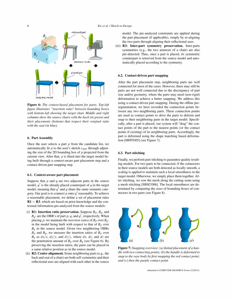
Figure 6: The context-based placement for parts. Top-leftfigure illustrates “insertion ratio" between bounding boxeswith bottom-left showing the target chair. Middle and rightcolumns show the source chairs with the back (in green) andtheir placements (bottom) that respect their original ratiowith the seat (in blue).
6. Part Assembly
Once the user selects a part p from the candidate list, weautomatically fit p to the user’s sketch cuser through adjust-ing the size of the 2D bounding box of p projected from thecurrent view. After that, p is fitted into the target model be-ing built through a context-aware part placement step and acontact-driven part snapping step.
6.1. Context-aware part placement
Suppose that p and q are two adjacent parts in the sourcemodel, q′ is the already placed counterpart of q in the targetmodel, meaning that q′ and q share the same semantic cate-gory. Our goal is to connect p onto q′ reasonably. To achievea reasonable placement, we define a set of placement rulesR1 ∼ R3, which are based on prior-knowledge and the con-textual information pre-analyzed from the source models:
(i) R1: Insertion ratio preservation. Suppose Bp, Bq, andBq′ are the OBB’s of part p, q, and q′, respectively. Whenplacing p, we maintain the insertion ratios of Bp over Bq′
in the model being built with respect to that of Bp overBq in the source model. Given two neighboring OBBsBp and Bq, we measure the insertion ratios of Bp overBq as dx/x, dy/y, and dz/z, where dx, dy, and dz arethe penetration amount of Bp over Bq (see Figure 6). Bypreserving the insertion ratios, the parts can be placed ina same relative position as in the source model.
(ii) R2: Center alignment. Some neighboring parts (e.g., theback and seat of a chair) are both self-symmetric and theirreflectional axes are aligned with each other in the source
model. The pre-analyzed constraints are applied duringthe part placement (if applicable), simply by re-aligningthe two parts through aligning their reflectional axes.
(iii) R3: Inter-part symmetry preservation. Inter-partssymmetries (e.g., the two armrests of a chair) are alsopre-detected. Thus, once a part is placed, its symmetriccounterpart is retreived from the source model and auto-matically placed according to the symmetry.
6.2. Contact-driven part snapping
After the part placement step, neighboring parts are wellconnected for most of the cases. However, there may still beparts are not well connected due to the discrepancy of partsize and/or geometry, where the parts may need (non-rigid)deformation to achieve a better snapping. We address thisusing a contact-driven part snapping. During the offline pre-segmentation, we have recorded the connection points be-tween any two neighboring parts. These connection pointsare used as contact points to drive the parts to deform andsnap to their neighboring parts in the target model. Specifi-cally, after a part is placed, our system will “drag” the con-tact points of the part to the nearest points (or the contactpoints if existing) of its neighboring parts. Accordingly, thepart is deformed using the shape matching based deforma-tion [MHTG05] (see Figure 7).
6.3. Part stitching
Finally, we perform part stitching to guarantee quality result-ing models. For two parts to be connected, if the connectorsin their source models are both detected as locally smooth, ascaling is applied to maintain such a local smoothness in thetarget model. Otherwise, we simply place them together. Af-ter stitching, we sow the mesh along the cutting seam usinga mesh stitching [SBSCO06]. The local smoothness are de-termined by comparing the sizes of bounding boxes of con-nectors in two parts (see Figure 8).
Figure 7: Snapping overview: (a) Initial placement of a han-dle with two connecting points; (b) the handle is deformed tosnap to the vase body by first snapping the red contact point;and (c) then the purple contact point.
submitted to COMPUTER GRAPHICS Forum (12/2012).
Xie et al. / Sketch-to-Design 7
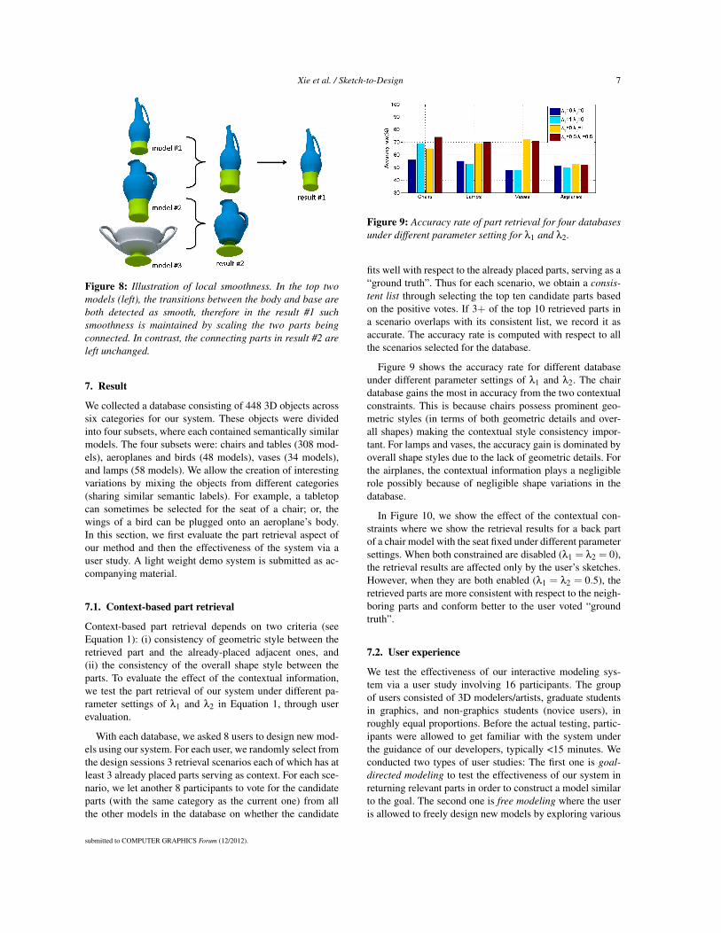
Figure 8: Illustration of local smoothness. In the top twomodels (left), the transitions between the body and base areboth detected as smooth, therefore in the result #1 suchsmoothness is maintained by scaling the two parts beingconnected. In contrast, the connecting parts in result #2 areleft unchanged.
7. Result
We collected a database consisting of 448 3D objects acrosssix categories for our system. These objects were dividedinto four subsets, where each contained semantically similarmodels. The four subsets were: chairs and tables (308 mod-els), aeroplanes and birds (48 models), vases (34 models),and lamps (58 models). We allow the creation of interestingvariations by mixing the objects from different categories(sharing similar semantic labels). For example, a tabletopcan sometimes be selected for the seat of a chair; or, thewings of a bird can be plugged onto an aeroplane’s body.In this section, we first evaluate the part retrieval aspect ofour method and then the effectiveness of the system via auser study. A light weight demo system is submitted as ac-companying material.
7.1. Context-based part retrieval
Context-based part retrieval depends on two criteria (seeEquation 1): (i) consistency of geometric style between theretrieved part and the already-placed adjacent ones, and(ii) the consistency of the overall shape style between theparts. To evaluate the effect of the contextual information,we test the part retrieval of our system under different pa-rameter settings of λ1 and λ2 in Equation 1, through userevaluation.
With each database, we asked 8 users to design new mod-els using our system. For each user, we randomly select fromthe design sessions 3 retrieval scenarios each of which has atleast 3 already placed parts serving as context. For each sce-nario, we let another 8 participants to vote for the candidateparts (with the same category as the current one) from allthe other models in the database on whether the candidate
Figure 9: Accuracy rate of part retrieval for four databasesunder different parameter setting for λ1 and λ2.
fits well with respect to the already placed parts, serving as a“ground truth”. Thus for each scenario, we obtain a consis-tent list through selecting the top ten candidate parts basedon the positive votes. If 3+ of the top 10 retrieved parts ina scenario overlaps with its consistent list, we record it asaccurate. The accuracy rate is computed with respect to allthe scenarios selected for the database.
Figure 9 shows the accuracy rate for different databaseunder different parameter settings of λ1 and λ2. The chairdatabase gains the most in accuracy from the two contextualconstraints. This is because chairs possess prominent geo-metric styles (in terms of both geometric details and over-all shapes) making the contextual style consistency impor-tant. For lamps and vases, the accuracy gain is dominated byoverall shape styles due to the lack of geometric details. Forthe airplanes, the contextual information plays a negligiblerole possibly because of negligible shape variations in thedatabase.
In Figure 10, we show the effect of the contextual con-straints where we show the retrieval results for a back partof a chair model with the seat fixed under different parametersettings. When both constrained are disabled (λ1 = λ2 = 0),the retrieval results are affected only by the user’s sketches.However, when they are both enabled (λ1 = λ2 = 0.5), theretrieved parts are more consistent with respect to the neigh-boring parts and conform better to the user voted “groundtruth”.
7.2. User experience
We test the effectiveness of our interactive modeling sys-tem via a user study involving 16 participants. The groupof users consisted of 3D modelers/artists, graduate studentsin graphics, and non-graphics students (novice users), inroughly equal proportions. Before the actual testing, partic-ipants were allowed to get familiar with the system underthe guidance of our developers, typically <15 minutes. Weconducted two types of user studies: The first one is goal-directed modeling to test the effectiveness of our system inreturning relevant parts in order to construct a model similarto the goal. The second one is free modeling where the useris allowed to freely design new models by exploring various
submitted to COMPUTER GRAPHICS Forum (12/2012).

8 Xie et al. / Sketch-to-Design
Figure 10: Comparison of retrieved results with and with-out contextual information: (a) the reference model and itscontours with user’s sketch, where the seat of chair hasbeen fixed; (b) the “ground truth” matching parts voted by8 participants; (c) the retrieved results according to onlythe user’s sketch, i.e., λ1 = λ2 = 0; (d) the results withλ1 = 1.0,λ2 = 0.0; (e) the results with λ1 = 0.0,λ2 = 1.0.(f) the results by considering both the user’s sketch and thefull contextual information, i.e., λ1 = 0.5,λ2 = 0.5.
part assemblies offered by our system. This tests the abilityof our system in supporting the conceptual design of new 3Dmodel. In all studies we used λ1 = λ2 = 0.5.
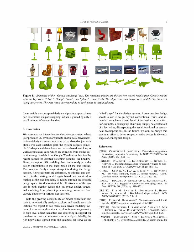
Goal-directed modeling. Although our system is designedfor open-ended modeling, in order to evaluate the perfor-mance of our retrieval module, we first conduct a goal di-rected modeling experiment. We give the users a collectionof photographs containing the target object and ask themto build 3D models as similar to the targets as she/he cando. We have conducted a “Google challenge”: we used fourkey words “chair”, “lamp”, “vase”, and “plane” to search forfour categories of photos from the Google Image search en-gine. For each category, the top five returned images werepresented to the used as the goals for modeling. The model-ing results were cross-rated among the participants. The topmodeled shapes (according to the user scores) for each goalphoto are in Figure 11. Additional user study results can befound in the accompanying material.
In order to investigate the effect of the contextual part re-trieval in the goal-directed modeling sessions, we record inTable 1 how many collected models were temporarily se-lected (number of mouse clicks by the user) during designinga new model. Two different parameter settings in Equation 1are compared. As expected, modeling time is shortened byconsidering contextual information.
Free modeling. In the second user study, we asked the 16participants to freely create ten different objects using oursystem. Here the users are not provided any specific target asgoal, except knowing the category she wants to model. Fig-
objects system parameters average clickschair λ1 = 0,λ2 = 0 15
λ1 = 0.5,λ2 = 0.5 9.5λ1 = 0,λ2 = 0 8
table λ1 = 0.5,λ2 = 0.5 6.5λ1 = 0,λ2 = 0 13
airplane λ1 = 0.5,λ2 = 0.5 11λ1 = 0,λ2 = 0 10
lamp λ1 = 0.5,λ2 = 0.5 8λ1 = 0,λ2 = 0 13
vase λ1 = 0.5,λ2 = 0.5 10
Table 1: The average numbers of the temporarily selectedmodels in the database for designing a new model under dif-ferent retrieval strategies, where λ1 = 0,λ2 = 0 means nocontextual information is considered for the retrieval.
ure 12 shows a portion of the modeling results produced bythe users. We note that the newly generated models containa fair amount of variation from the original database models(see the accompanying material for all the database models).According to their modeling experience, about 85% of theparticipants confirmed in questionnaire that they have sig-nificantly benefitted from the intermediate modeling sugges-tions and the ability to change viewpoint during modeling.Among the rest 15%, most preferred sketching all parts byhand than adopting the automatically suggested ones.
Table 2 shows the response time of retrieval and assemblyper part. Since we use the inverted index structure, the run-ning time on part retrieval does not dependent on the scaleof a dataset, but rather mainly on the amount of geometricvariations of the 3D models within the dataset. The less vari-ations in the model set, the more shared visual words in theirBOW features, which consequently means the search spaceresulted by the inverted indexing is denser (See Section 5.3).
Limitations. The current system, however, is limited in itscreation of finer level of geometric textures (e.g., surface pat-terns) and micro-structure assembly. Although such texturescan possibly be suggested through context (e.g., a beamedchair seat is likely to have a matching beamed back), currentsketching tools do not support their direct creation. Also, we
Dataset Size Retrieval AssemblyChair 172 14 41Table 136 13 14Chair+Table 308 14 20Lamp 58 13 21Airplane+Bird 48 297 23Vase 34 294 77
Table 2: Response time of retrieval and assembly in millisec-onds on various datasets.
submitted to COMPUTER GRAPHICS Forum (12/2012).
Xie et al. / Sketch-to-Design 9
Figure 11: Examples of the “Google challenge" test. The reference photos are the top five search results from Google enginewith the key words “chair", “lamp", “vase", and “plane", respectively. The objects in each image were modeled by the usersusing our system. The best result corresponding to each photo is displayed here.
focus mainly on conceptual design and produce approximatepart assemblies via part snapping, which is guided by only asmall number of contact handles.
8. Conclusion
We presented an interactive sketch-to-design system whereuser provided 2D strokes are used to enable data-driven navi-gation of design spaces comprising of part-based object vari-ations. For each sketched part, the system suggests plausi-ble 3D shape candidates based on curved-based matching aswell as contextual cues, which are extracted from model col-lections (e.g., models from Google Warehouse). Inspired byrecent success of assisted sketching systems like Shadow-Draw, we support 3D modeling that continuously providesdesign suggestions to the users based on the user strokes.The user can freely change viewpoints during the designsession. Retrieved parts are deformed, positioned, and con-nected to the existing model, again based on context infor-mation, as the user implicitly is guided through the possibledesign space. We demonstrated the effectiveness of the sys-tem in both creative design (i.e., no preset design targets)and modeling from photo inpirations (e.g., re-model fromGoogle Photos) via various user sessions.
With the growing accessibility of model collections andtools to automatically analyze, explore, and handle such col-lections, we expect to see many data-driven modeling sys-tems. An important direction to explore is to relate geometryto high level object semantics and also bring in support forlow-level texture and micro-structural analysis. Ideally, therich knowledge learned from the database can serve as the
“mind’s eye” for the design system. A true creative designshould allow us to go beyond conventional forms and se-mantics, to achieve a new level of aesthetics and comfort.For example, a conceptual chair may simply be created outof a few wires, disrespecting the usual functional or seman-tical decompositions. In the future, we want to bridge thisgap in an effort to better support creative design in the earlystages of conceptual design.
References[CK10] CHAUDHURI S., KOLTUN V.: Data-driven suggestions
for creativity support in 3d modeling. In ACM TOG (SIGGRAPHAsia) (2010), pp. 183:1–10.
[CKGK11] CHAUDHURI S., KALOGERAKIS E., GUIBAS L.,KOLTUN V.: Probabilistic reasoning for assembly-based 3d mod-eling. In ACM TOG (SIGGRAPH) (2011), pp. 35:1–10.
[CTSO03] CHEN D.-Y., TIAN X.-P., SHEN Y.-T., OUHYOUNGM.: On visual similarity based 3D model retrieval. Comp.Graphics Forum (Eurographics) 22, 3 (2003), 223–232.
[DFRS03] DECARLO D., FINKELSTEIN A., RUSINKIEWICZ S.,SANTELLA A.: Suggestive contours for conveying shape. InProc. SIGGRAPH (2003), pp. 848–855.
[ERB∗12] EITZ M., RICHTER R., BOUBEKEUR T., HILDE-BRAND K., ALEXA M.: Sketch-based shape retrieval. ACMTOG (SIGGRAPH) (2012), 5:1–10.
[FH10] FISHER M., HANRAHAN P.: Context-based search for 3dmodels. ACM Transactions on Graphics 29 (2010).
[FKS∗04] FUNKHOUSER T., KAZHDAN M., SHILANE P., MINP., KIEFER W., TAL A., RUSINKIEWICZ S., DOBKIN D.: Mod-eling by example. In Proc. SIGGRAPH (2004), pp. 652–663.
[FMK∗03] FUNKHOUSER T., MIN P., KAZHDAN M., CHEN J.,HALDERMAN A., DOBKIN D., JACOBS D.: A search engine for
submitted to COMPUTER GRAPHICS Forum (12/2012).

10 Xie et al. / Sketch-to-Design
Figure 12: Selection of models created by users of our system.
3D models. ACM Transactions on Graphics 22, 1 (Jan. 2003),83–105.
[FSH11] FISHER M., SAVVA M., HANRAHAN P.: Characteriz-ing structural relationships in scenes using graph kernels. ACMTrans. Graph. 30 (August 2011), 34:1–12.
[HKG11] HUANG Q., KOLTUN V., GUIBAS L.: Joint shape seg-mentation using linear programming. In ACM TOG (SIGGRAPHAsia) (2011), pp. 125:1–11.
[JTRS12] JAIN A., THORMÄHLEN T., RITSCHEL T., SEIDELH.-P.: Exploring shape variations by 3d-model decompositionand part-based recombination. Comp. Graph. Forum (Proc. Eu-rographics 2012) 31, 2 (2012).
[KCKK12] KALOGERAKIS E., CHAUDHURI S., KOLLER D.,KOLTUN V.: A probabilistic model of component-based shapesynthesis. ACM Transactions on Graphics 31, 4 (2012), 55:1–11.
[KHS10] KALOGERAKIS E., HERTZMANN A., SINGH K.:Learning 3d mesh segmentation and labeling. In ACM TOG (SIG-GRAPH) (2010), pp. 102:1–12.
[LF08] LEE J., FUNKHOUSER T.: Sketch-based search and com-position of 3D models. In EUROGRAPHICS Workshop onSketch-Based Interfaces and Modeling (June 2008).
[LZC11] LEE Y. J., ZITNICK L., COHEN M.: Shadowdraw:Real-time user guidance for freehand drawing. ACM TOG (SIG-GRAPH) (2011), 27:1–9.
[MGP06] MITRA N. J., GUIBAS L. J., PAULY M.: Partial andapproximate symmetry detection for 3d geometry. In ACM SIG-GRAPH 2006 Papers (New York, NY, USA, 2006), SIGGRAPH’06, ACM, pp. 560–568.
[MHTG05] MÜLLER M., HEIDELBERGER B., TESCHNER M.,GROSS M.: Meshless deformations based on shape matching.ACM TOG (SIGGRAPH) 24, 3 (2005), 471–478.
[OFCD02] OSADA R., FUNKHOUSER T., CHAZELLE B.,DOBKIN D.: Shape distributions. ACM Trans. Graph. 21 (Octo-ber 2002), 807–832.
[OLGM11] OVSJANIKOV M., LI W., GUIBAS L., MITRA N. J.:Exploration of continuous variability in collections of 3d shapes.ACM TOG (SIGGRAPH) 30 (August 2011), 33:1–10.
[PKM∗11] PACZKOWSKI P., KIM M. H., MORVAN Y., DORSEYJ., RUSHMEIER H., O’SULLIVAN C.: Insitu: Sketching archi-tectural designs in context. ACM TOG (SIGGRAPH Asia) 30, 6(2011), 182:1–10.
[SBSCO06] SHARF A., BLUMENKRANTS M., SHAMIR A.,COHEN-OR D.: Snappaste: An interactive technique for easymesh composition. In Proc. Pacific Graphics (2006), pp. 835–844.
[SFCH12] SHEN C.-H., FU H., CHEN K., HU S.-M.: Structurerecovery by part assembly. ACM TOG (SIGGRAPH Asia) (2012),to appear.
[SI07] SHIN H., IGARASHI T.: Magic canvas: interactive designof a 3-d scene prototype from freehand sketches. In Proc. ofGraphics Interface (2007), pp. 63–70.
[SvKK∗11] SIDI O., VAN KAICK O., KLEIMAN Y., ZHANG H.,COHEN-OR D.: Unsupervised co-segmentation of a set of shapesvia descriptor-space spectral clustering. In ACM TOG (SIG-GRAPH Asia) (2011), pp. 126:1–9.
[SXY∗11] SHAO T., XU W., YIN K., WANG J., ZHOU K., GUOB.: Discriminative sketch-based 3d model retrieval via robustshape matching. Computer Graphics Forum 30, 7 (2011).
[SZ03] SIVIC J., ZISSERMAN A.: Video google: a text retrievalapproach to object matching in videos. In Computer Vision,2003. Proceedings. Ninth IEEE International Conference on (oct.2003), pp. 1470 –1477 vol.2.
[WMB99] WITTEN I. H., MOFFAT A., BELL T. C.: ManagingGigabytes: Compressing and Indexing Documents and Images.Morgan Kaufmann Publishing, 1999.
[XLZ∗10] XU K., LI H., ZHANG H., COHEN-OR D., XIONGY., CHENG Z.-Q.: Style-content separation by anisotropic partscales. In ACM TOG (SIGGRAPH Asia) (2010), pp. 184:1–10.
[XZCOC12] XU K., ZHANG H., COHEN-OR D., CHEN B.: Fitand diverse: Set evolution for inspiring 3d shape galleries. ACMTOG (SIGGRAPH) (2012), 57:1–10.
[ZS84] ZHANG T. Y., SUEN C. Y.: A fast parallel algorithm forthinning digital patterns. Commun. ACM 27 (March 1984), 236–239.
submitted to COMPUTER GRAPHICS Forum (12/2012).