skf lahd 500-1000
TRANSCRIPT

SKF LAHD 500-1000
Instructions for useMode d’emploiBedienungsanleitungInstrucciones de uso
Manuale d’istruzioniInstruções de uso使用说明书Инструкция по эксплуатации


English
English 2
Fran
çais
Français 9
Deu
tsch
Deutsch 15
Esp
añol
Español 21
Italian
o
Italiano 27
Portu
guês
Português 33
中文
中文 39
Русски
й
Русский 45


3SKF LAHD 500-1000
1. Application .......................................................................................................4
2. Description .......................................................................................................4
3. Technical data ..................................................................................................5
4. Instructions for use ..........................................................................................64.1 Installation ...................................................................................................................... 6
5. Maintenance and trouble shooting ....................................................................85.1 Maintenance ................................................................................................................... 85.2 Trouble shooting ............................................................................................................ 8
Table of contents
Original instructions
English

4 SKF LAHD 500-1000
1. Application
The SKF Oil levellers, type LAHD, are designed for automatic adjustment of the optimal oil lubrication level within a bearing housing, gearbox, crankcase or similar oil bath application. It effectively solves the problem of adjusting the correct oil level during running conditions rather than during standstill. Furthermore, it will automatically compensate for oil leakage and offers the possibility for visual inspection of the oil level. The oil leveller will not compensate if the oil level is too high.
2. Description
The oil leveller basically consists of two communicating oil reservoirs, one on top of the other. The lower reservoir is in direct contact with the application and hence its oil level is the same as the oil level inside the application. Through a ventilation system the lower reservoir is in direct contact with the ambient air.
The upper reservoir is an airtight container storing replacement oil. Through its extended neck, which dips into the oil of the lower reservoir, the two reservoirs are in direct connection with each other. However oil can only flow from the upper to the lower reservoir once the oil level in the lower reservoir goes below the preset level, allowing air to flow through the extended neck to the upper reservoir.
Oil inlet
Upper cover
Upper reservoir
Spring loaded valve
Set of gaskets
Extended neckLower reservoir Oil level
Fixation nut
Magnetic, drainage plug
Assembly drawing oil leveller

5SKF LAHD 500-1000
3. Technical data
Boundary dimensions
- LAHD 500 Ø 91 mm x 290 mm high (3,6 x 11,4 in)
- LAHD 1000 Ø 122 mm x 290 mm high (4,8 x 11,4 in)
Reservoir volume
- LAHD 500 500 ml (17 fl. oz. US)
- LAHD 1000 1 000 ml (34 fl. oz. US)
Container material Polycarbonate, aluminium
Temperature range permitted - 20 .. 70 °C (-5 .. 160 °F)
Permissible humidity 0 - 100 %
Length of connecting tube 600 mm (2 feet)
Connection thread G 1/2
Tube material Polyurethane
O-ring material NBR - 70 Shore
Gaskets NBR - 80 Shore
6 pieces, 3 pcs 3 x 64,5 x 82,5 mm 2 pcs 2 x 64,5 x 82,5 mm 1 pcs 2 x 62,5 x 82,5 mm
Other material Aluminium, Bronze, Stainless Steel
Suitable oil types Mineral and synthetic oils
English

6 SKF LAHD 500-1000
4. Instructions for use
4.1 Installation
1. Determine the required oil level in the application during operation. For oil lubricated bearing housings this is normally defined as two millimetres (0,08 in) above the inner diameter of the outer ring of the bearing. It is however, strongly advised to check the recommendations from the bearing manufacturer. Similar recommendations exist for gearboxes and crank shaft casings.
2. Determine the best location for the installation of the support bracket assembly. The oil leveller must not be more than 60 cm (2 feet, length of plastic tube) from the application.
3. Adjust the support bracket, which holds the oil leveller to approximately 50 mm (2 in) below the required oil level.
4. Separate the lower and the upper reservoirs from each other.5. Connect the lower reservoir to the support bracket by means of the fixation nut at the
bottom of the oil leveller.6. Adjust the height of the oil leveller so that the required oil level is between the two
lines marked on the lower reservoir.7. Measure and cut the plastic tube to the adequate length.8. Prepare both ends of the tube with the swivel connectors. Start by sliding the swivel
adapter (with the thread facing outwards) on top of the tube. Insert the copper sleeve into the tube and slide the copper ring on top of the sleeve.
Bracket assembly Bracket dimensions
Tube & coupling assembly
9. Thread the two connection couplings (G 1/2) onto the oil leveller and the application and connect the tube. Firmly tighten the swivel adapters.
10. Ensure there are no bends or kinks in the tube preventing the oil to flow freely from the oil leveller to the application.

7SKF LAHD 500-1000
oil
level
oil
oiloil
levellevel
level
Installation
11. Adjust the oil level in the application to the required level and assure that this corresponds to a level between the two lines marked on the lower reservoir. If necessary, adjust the height of the lower reservoir by means of the support bracket screw.
12. Screw the upper reservoir tightly onto the lower reservoir ensuring that the extended neck is flush with the oil level in the lower reservoir. Use the six rubber gaskets to obtain the correct height. (Ensure the gasket with the smallest bore remains on top).
13. For high precision applications use the support bracket screw for the fine tuning (otherwise the accuracy will depend on the thickness of the gaskets).
14. Unscrew the cover of the upper reservoir and fill it with the same oil as used in the application.
15. Screw back the cover tightly, ensuring that no air can enter into the upper reservoir. This will also open the valve at the bottom of the upper reservoir and hence connect the upper and lower reservoir to each other.
16. Start the machine. As the oil in the application will lower due to splashing, oil will flow from the lower reservoir into the application, exposing the extended neck to open air. This will allow air to enter the upper reservoir and hence oil to flow down to the lower reservoir. Once the oil has reached the preset level, air can no longer pass to the upper reservoir, effectively stopping the flow of oil.
N.B.: During stand-still the oil will stop splashing and the level in the application will rise. As a consequence the oil level in the oil leveller will also rise above the preset level.
English

8 SKF LAHD 500-1000
5. Maintenance and trouble shooting
5.1 Maintenance
Regularly:• Check and refill the upper oil reservoir with new, clean oil.• Clean the oil leveller. For this purpose the lower reservoir is equipped with a drainage
neck with a magnetic plug.
5.2 Trouble shooting
In case of different oil levels in the application and the oil leveller check that:• The application is provided with a ventilation nipple preventing over/under pressure.
In the case the oil continues to flow from the upper reservoir despite the pre-set level having been reached:• Ensure the cover and the oil inlet on the upper reservoir is properly sealed.
In the case of excessive oil consumption check the application for leakage.

9SKF LAHD 500-1000
1. Application .....................................................................................................10
2. Description .....................................................................................................10
3. Caractéristiques techniques ............................................................................11
4. Mode d’emploi ................................................................................................124.1 Installation ....................................................................................................................12
5. Entretien et interventions en cas de panne .....................................................145.1 Entretien .......................................................................................................................145.2 Interventions en cas de panne ...................................................................................14
Table des matières
Traduction extraite du mode d’emploi d’origine
Fran
çais

10 SKF LAHD 500-1000
1. Application
Les niveleurs d’huile SKF, de type LAHD, sont conçus pour ajuster automatiquement le niveau optimal de lubrification en huile d’un logement de roulement, d’une boîte d’engrenages, d’un carter ou autre application de bain d’huile similaire. Le niveleur résout le problème de réglage du niveau d’huile correct pendant des conditions de fonctionnement plutôt qu’en arrêt.De plus, il compense automatiquement les fuites d’huile et permet de contrôler visuellement le niveau d’huile. Le niveleur d’huile ne compense pas si le niveau d’huile est trop élevé.
2. Description
Le niveleur d’huile consiste essentiellement en deux réservoirs d’huile communicants, disposés l’un sur l’autre. Le réservoir inférieur est en contact direct avec l’application et son niveau d’huile est par conséquent égal au niveau d’huile de l’application. Un système de ventilation met le réservoir inférieur en contact avec l’air ambiant.
Le réservoir supérieur est un contenant étanche à l’air qui stocke l’huile de rechange. Son col prolongé, qui plonge dans l’huile du réservoir inférieur, met les deux réservoirs en contact direct l’un avec l’autre. Cependant, l’huile ne peut passer du réservoir supérieur au réservoir inférieur que si le niveau d’huile du réservoir inférieur baisse en deçà du niveau préréglé, permettant ainsi àà l’air de passer, par le col prolongé, vers le réservoir supérieur.
Admission d’huile
Couvercle supérieur
Réservoir supérieur
Soupape à ressort
Jeu de joints d’étanchéité
Col prolongéRéservoir inférieur Ecrou de fixation
Ecrou de fixation
Bouchon de vidange magnétique
Plan d’assemblage du niveleur d’huile

11SKF LAHD 500-1000
3. Caractéristiques techniques
Dimensions d’encombrement
- LAHD 500 Ø 91 mm x 290 mm de hauteur
- LAHD 1000 Ø 122 mm x 290 mm de hauteur
Volume du réservoir
- LAHD 500 500 ml
- LAHD 1000 1 000 ml
Matériau du réservoir Polycarbonate, aluminium
Plage de températures admissible
- 20 .. 70 °C
Humidité admissible 0 - 100 %
Longueur du tube de 600 mm
raccordement G 1/2
Filetage du raccord Polyuréthanne
Matériau du tube NBR - 70 Shore
Matériau du joint torique NBR - 80 Shore
Joints d’étanchéité 6 unités, 3 unités 3 x 64,5 x 82,5 mm 2 unités 2 x 64,5 x 82,5 mm 1 unités 2 x 62,5 x 82,5 mm
Autres matériaux Aluminium, bronze, acier inoxydable
Types d’huile appropriés huiles minérales et synthétiques
Fran
çais

12 SKF LAHD 500-1000
4. Mode d’emploi
4.1 Installation
1. Déterminez le niveau d’huile nécessaire à l’application pendant son fonctionnement. Pour les logements de roulement lubrifiés à l’huile, ce niveau est normalement fixé à deux millimètres au-dessus du diamètre interne de la bague intérieure du roulement. Il est toutefois vivement conseillé de vérifier les recommandations du fabricant du roulement. Il existe des recommandations pour les boîtes d’engrenage et les carters de vilebrequin.
2. Déterminez le meilleur endroit pour l’installation de l’assemblage du support. Le niveleur d’huile ne doit pas être distant de plus de 60 cm (longueur du tube plastique) par rapport à l’application.
3. Ajustez le support qui retient le niveleur d’huile à environ 50 mm au-dessus du niveau d’huile requis.
4. Séparez les réservoirs inférieur et supérieur.5. Fixez le réservoir inférieur au support au moyen des deux écrous de fixation au bas
du niveleur d’huile.6. Ajustez la hauteur du niveleur d’huile de manière à ce que le niveau d’huile requis se
trouve entre les deux repères indiqués sur le réservoir inférieur.7. Mesurez et découpez le tube plastique à la longueur adéquate.8. Préparez les deux extrémités du tube avec les raccords pivotants. Commencez par
glissez l’adaptateur pivotant (son filetage dirigé vers l’extérieur) par le haut du tube. Insérez le manchon de cuivre dans le tube et glissez la bague de cuivre par le haut du manchon.
Assemblage du support Dimensions du support
Assemblage du tube et des raccords
9. Vissez les deux raccords (G 1/2) sur le niveleur d’huile et l’application puis raccordez le tube. Serrez fermement les adaptateurs pivotants.

13SKF LAHD 500-1000
10. Assurez-vous que le tube ne comporte ni courbures ni vrilles empêchant l’huile de s’écouler librement entre le niveleur d’huile et l’application.
huile
niveau
huile
huilehuile
niveauniveau
niveau
Installation
11. Ajustez le niveau d’huile dans l’application au niveau requis et assurez-vous qu’il correspond au niveau situé entre les deux repères du réservoir inférieur. Si nécessaire, ajustez la hauteur du réservoir inférieur à l’aide de la vis du support.
12. Vissez solidement le réservoir supérieur sur le réservoir inférieur en vous assurant que le col prolongé est de fleur du niveau d’huile du réservoir inférieur. Utilisez les deux joints étanches en caoutchouc pour obtenir la bonne hauteur. (Assurez-vous que le joint étanche dont le trou est le plus étroit reste en haut).
13. Pour des applications de haute précision, utilisez la vis du support pour le réglage fin (sinon la précision dépendra de l’épaisseur des joints d’étanchéité).
14. Dévissez le couvercle du réservoir supérieur et remplissez ce dernier avec la même huile utilisée dans l’application.
15. Revissez solidement le couvercle et assurez-vous que l’air ne peut pas pénétrer dans le réservoir supérieur. Cela ouvrira également la soupape située au fond du réservoir supérieur et donc mettra en communication les réservoirs supérieur et inférieur.
16. Mettez la machine en marche. Comme l’huile présente dans l’application baissera en raison du barbotage, l’huile passera du réservoir inférieur versà l’application, exposant ainsi le col prolongé à l’air libre. Cela permettra à l’air de pénétrer dans le réservoir supérieur et, par conséquent, à l’huile de passer au réservoir inférieur. Une fois que l’huile aura atteint le niveau préréglé, l’air ne pourra plus passer vers le réservoir supérieur, arrêtant efficacement l’écoulement d’huile.
N.B. : Lorsque la machine est en arrêt, l’huile s’arrête de barboter et le niveau d’huile dans l’application augmente. En conséquence de quoi, le niveau d’huile du niveleur d’huile augmente également au-dessus du niveau préréglé.
Fran
çais

14 SKF LAHD 500-1000
5. Entretien et interventions en cas de panne
5.1 Entretien
Régulièrement :• Contrôlez et ajoutez de l’huile neuve et propre dans le réservoir supérieur.• Nettoyez le niveleur d’huile. Pour ce faire, le réservoir inférieur est équipé d’un col de
vidange à bouchon magnétique.
5.2 Interventions en cas de panne
Si vous constatez des niveaux d’huile différents dans l’application et le niveleurd’huile, vérifiez si :• l’application est dotée d’un embout d’aération empêchant la surpression et la
dépression.
Au cas où l’huile continue de s’écouler du réservoir supérieur bien que le niveau préréglé ait été atteint :• assurez-vous que le couvercle et l’admission d’huile du réservoir supérieur sont bien
étanches.
En cas de consommation d’huile excessive, contrôlez l’application quant à la présence de fuite.

15SKF LAHD 500-1000
1. Anwendung ....................................................................................................16
2. Beschreibung .................................................................................................16
3. Technische Daten ...........................................................................................17
4. Bedienungsanleitung ......................................................................................184.1 Montage ........................................................................................................................18
5. Wartung und Störungsbeseitigung ..................................................................205.1 Wartung ........................................................................................................................205.2 Störungsbeseitigung ...................................................................................................20
Inhalt
Übersetzung der Original-Bedienungsanleitungen
Deu
tsch

16 SKF LAHD 500-1000
1. Anwendung
Der SKF Ölstandswächter, Typ LAHD, wurde zur automatischen Regulierung desoptimalen Schmierölstands in einem Lagergehäuse, Getriebegehäuse, Kurbelgehäuse oder einer ähnlichen Ölbadanwendung entworfen. Damit wird das Problem der Regulierung des korrekten Ölstands während des Betriebs statt während des Stillstands auf wirksame Weise gelöst. Außerdem kompensiert der Ölstandswächter Ölleckagen automatisch und bietet die Möglichkeit der Sichtkontrolle des Ölstands. Ein zu hoher Ölstand kann vom Ölstandswächter nicht kompensiert werden.
2. Beschreibung
Der SKF Ölstandswächter besteht aus zwei kommunizierenden Ölbehältern. Der untere Behälter ist direkt mit der Anwendung verbunden und hat daher den gleichen Ölstand wie die Anwendung. Durch ein Lüftungsrohr hat der untere Ölbehälter Kontakt zur Umgebungsluft.
Der obere Behälter ist luftdicht verschlossen und enthält die Nachfüll-Ölmenge. Die beiden Behälter sind über einen verlängerten Stutzen, der in das Öl im unteren Behälter eintaucht, miteinander verbunden. Aus dem oberen Behälter kann nur dann Öl ausfließen, wenn der Ölstand im unteren Behälter unter das vorher eingestellte Niveau absinkt, da nur dann Luft über den verlängerten Stutzen in den oberen Behälter gelangen kann. Der eingestellte Ölstand entspricht daher dem unteren Ende des verlängerten Stutzens.
Öleinlass
obere Abdeckung
oberer Behälter
Rückschlagventil mit Feder
Dichtungssatz
verlängerter Stutzenunterer Behälter Ölstand
Befestigungsmuttern
magnetischer Ablassstopfen
Montagezeichnung Ölstandswächter

17SKF LAHD 500-1000
3. Technische Daten
Außenabmessungen:
- LAHD 500 Ø 91 mm x 290 mm Höhe
- LAHD 1000 Ø 122 mm x 290 mm Höhe
Nachfüllvolumen:
- LAHD 500 500 ml
- LAHD 1000 1 000 ml
Behältermaterial Polykarbonat, Aluminium
Umgebungstemperatur - 20 bis 70 °C
Zulässige Luftfeuchte 0 - 100 %
Länge des Anschlussschlauchs
600 mm
Anschlussgewinde G 1/2
Schlauchmaterial Polyurethan
O-Ringmaterial NBR - 70 Shore
Dichtungen NBR - 80 Shore
6 Stück, 3 Stück 3 x 64,5 x 82,5 mm 2 Stück 2 x 64,5 x 82,5 mm 1 Stück 2 x 62,5 x 82,5 mm
Weitere Werkstoffe Aluminium, Bronze, Edelstahl
Geeignete Öle Mineral- und Syntheseöle
Deu
tsch

18 SKF LAHD 500-1000
4. Bedienungsanleitung
4.1 Montage
1. Den erforderlichen Ölstand in der Anwendung während des Betriebs bestimmen. Für ölgeschmierte Lagergehäuse wird dieser normalerweise als zwei Millimeter über dem inneren Durchmesser des äußeren Rings des Lagers definiert. Es wird jedoch dringend empfohlen, die Empfehlungen des Lagerherstellers zu beachten. Entsprechende Empfehlungen gibt es für Getriebegehäuse und Kurbelwellengehäuse.
2. Bestimmen Sie die beste Stelle für die Installation des Stützbügelaufbaus. Der Ölstandswächter darf nicht mehr als 60 cm (Länge des Plastikschlauchs) von der Anwendung entfernt sein.
3. Den Stützbügel, der den Ölstandswächter trägt, etwa 50 mm unter dem erforderlichen Ölstand anbringen.
4. Den oberen und den unteren Behälter voneinander lösen.5. Den unteren Behälter mit den zwei Befestigungsmuttern, die sich unten am
Ölstandswächter befinden, am Stützbügel befestigen.6. Die Höhe des Ölstandswächters so anpassen, dass der erforderliche Ölstand zwischen
den zwei Linien liegt, die auf dem unteren Behälter angegeben sind.7. Den Verbindungsschlauch messen und auf die richtige Länge zuschneiden.8. Beide Enden des Schlauches mit den Gelenkverbindungen versehen. Dabei erst den
Gelenkadapter (mit nach außen weisendem Gewinde) auf den Schlauch schieben. Die Kupfer-Laufbuchse in den Schlauch stecken und den Kupferring auf die Buchse schieben.
Bügelaufbau Bügelabmessungen
Schlauch-und Kupplungsaufbau
9. Die zwei Verbindungskupplungen (G 1/2) auf den Ölstandswächter und die Anwendung schrauben und den Schlauch anbringen. Die Gelenkadapter fest anziehen.
10. Der Schlauch darf dabei keine Krümmungen und Knicke aufweisen, die den freien Fluss des Öls vom Ölstandswächter zur Anwendung verhindern.

19SKF LAHD 500-1000
Öl
stand
Öl
ÖlÖl
standstand
stand
Montage
11. Den Ölstand in der Anwendung auf den erforderlichen Stand bringen. Dieser muss mit einem Ölstand übereinstimmen, der zwischen den zwei Linien liegt, die auf dem unteren Behälter angegeben sind. Falls erforderlich die Höhe des unteren Behälters mit Hilfe der Stützbügelschraube anpassen.
12. Den oberen Behälter fest auf den unteren Behälter schrauben, wobei darauf zu achten ist, dass der verlängerte Hals in einer Ebene mit dem Ölstand des unteren Behälters liegt. Die sechs Gummidichtungen zur Einstellung der richtigen Höhe verwenden. (Die Dichtung mit der kleinsten Bohrung muss oben bleiben).
13. Für Präzisionsanwendungen wird die Stützbügelschraube zur Feineinstellung verwendet (andernfalls ist die Genauigkeit von der Dicke der Dichtungen abhängig).
14. Die Abdeckung vom oberen Behälter schrauben und diesen mit demselben Öl füllen, das auch in der Anwendung verwendet wird.
15. Die Abdeckung wieder fest anschrauben, so dass keine Luft in den oberen Behälter gelangen kann. Dies wird auch das Ventil auf dem Boden des unteren Behälters öffnen und so den oberen und den unteren Behälter miteinander verbinden.
16. Die Maschine starten. Da das Öl in der Anwendung durch Verspritzen weniger wird, fließt Öl aus dem unteren Behälter in die Anwendung und der verlängerte Stutzen wird bloßgelegt und ist jetzt von Luft umgeben. Dadurch kann Luft in den oberen Behälter eindringen und Öl in den unteren Behälter fließen. Wenn das Öl den voreingestellten Stand erreicht hat, kann die Luft nicht mehr in den oberen Behälter gelangen und somit wird der Fluss des Öls wirksam gestoppt.
N.B.: Während des Stillstands wird das Öl sich wieder sammeln und der Ölstand in der Anwendung wird ansteigen. Dies hat zur Folge, dass auch der Ölstand im Ölstandswächter über den voreingestellten Stand ansteigt.
Deu
tsch

20 SKF LAHD 500-1000
5. Wartung und Störungsbeseitigung
5.1 Wartung
Regelmäßig:• Den oberen Ölbehälter kontrollieren und mit neuem, sauberem Öl auffüllen.• Den Ölstandswächter reinigen. Zu diesem Zweck ist der untere Behälter mit einem
magnetischen Ablassstopfen versehen.
5.2 Störungsbeseitigung
Bei verschiedenen Ölständen in der Anwendung und im Ölstandswächterkontrollieren, ob:• die Anwendung mit einem Lüftungsnippel zur Vermeidung von Über-/Unterdruck
versehen ist.
Wenn weiterhin Öl aus dem oberen Behälter läuft, obwohl der voreingestellteStand erreicht wurde:• sicherstellen, dass die Abdeckung und der Öleinlass auf dem oberen Behälter
ordnungsgemäß abgedichtet sind.
Bei exzessivem Ölverbrauch die Anwendung auf mögliche Lecks kontrollieren.

21SKF LAHD 500-1000
1. Aplicación .......................................................................................................22
2. Descripción ....................................................................................................22
3. Datos técnicos ................................................................................................23
4. Instrucciones de uso .......................................................................................244.1 Instalación .....................................................................................................................24
5. Mantenimiento y resolución de problemas ......................................................265.1 Mantenimiento .............................................................................................................265.2 Resolución de problemas ............................................................................................26
Índice
Traducción de las instrucciones originales
Esp
añol

22 SKF LAHD 500-1000
1. Aplicación
Los niveladores de aceite SKF de la serie LAHD han sido diseñados para llevar a cabo un ajuste automático del nivel de aceite dentro del soporte de un rodamiento, una caja de engranajes, un cárter o en aplicaciones similares que requieren lubricación con aceite. Los niveladores de aceite SKF consisten en una solución eficaz a los problemas de ajuste del nivel correcto de aceite, ya que permiten realizarlo durante el funcionamiento de la máquina en lugar de realizar el ajuste cuando la aplicación se encuentra inactiva.Además, compensan automáticamente las fugas de aceite y su diseño permite la visualización del nivel de aceite. Cuando este nivel es demasiado elevado, el nivelador de aceite no realiza ninguna acción de compensación.
2. Descripción
El nivelador de aceite consta básicamente de dos depósitos de aceite comunicantes, uno situado encima del el otro. El depósito inferior está directamente en contacto con la aplicación y, por tanto, su nivel de aceite es el mismo que el nivel de aceite que se encuentra dentro de la aplicación. Gracias a un sistema de ventilación, este depósito está en contacto directo con el aire exterior.
El depósito superior está situado en un recipiente hermético que contiene el aceite de recambio. Los dos depósitos se encuentran directamente conectados a través de un cuello que se extiende desde el depósito superior hasta sumergirse en el aceite del depósito inferior. No obstante, el aceite solamente puede circular del depósito superior al inferior cuando el nivel de aceite de este último sea inferior al nivel predeterminado, permitiendo que el aire circule por el cuello hacia el depósito superior.
Entrada de aceite
Cubierta superior
Depósito superior
Válvula de resorte
Conjunto de juntas
Cuello extendidoDepósito inferior nivel de aceite
Tuercas de fijación
Tapón de drenaje magnético
Plano de ensamblaje del nivelador de aceite

23SKF LAHD 500-1000
3. Datos técnicos
Dimensiones
- LAHD 500 Ø 91 mm x 290 mm de alto
- LAHD 1000 Ø 122 mm x 290 mm de alto
Volumen del depósito
- LAHD 500 500 ml
- LAHD 1000 1.000 ml
Material del recipiente Policarbonato, aluminio
Rango de temperatura permitido
–20 a +70 °C
Humedad permisible 0 - 100 %
Longitud del tubo de conexión 600 mm
Conectores G 1/2
Material del tubo Poliuretano
Material de la junta tórica NBR - 70 Shore
Juntas NBR - 80 Shore
6 unidades, 3 unids. 3 x 64,5 x 82,5 mm 2 unids. 2 x 64,5 x 82,5 mm 1 unids. 2 x 62,5 x 82,5 mm
Otros materiales Aluminio, bronce, acero inoxidable
Aceites compatibles Aceites minerales y sintéticos
Esp
añol

24 SKF LAHD 500-1000
4. Instrucciones de uso
4.1 Instalación
1. Determine el nivel de aceite que la aplicación requerirá durante su funcionamiento. En los soportes para rodamientos lubricados con aceite, este nivel se define normalmente como 2 milímetros por encima del diámetro interior del aro exterior del rodamiento; no obstante, se recomienda encarecidamente comprobar las recomendaciones del fabricante de rodamientos. Existen recomendaciones similares para las cajas de engranajes y para el cárter del cigüeñal.
2. Determine el lugar idóneo para la instalación de la abrazadera. El nivelador de aceite no debe encontrarse a más de 60 cm (longitud de tubo de plástico) de la aplicación.
3. Ajuste la abrazadera que sujeta el nivelador de aceite a aproximadamente 50 mm por debajo del nivel de aceite necesario.
4. Separe los depósitos inferior y superior uno del otro.5. Conecte el depósito inferior al soporte mediante las dos tuercas de fijación situadas
en la parte inferior del nivelador de aceite.6. Ajuste la altura del nivelador de aceite de forma que el nivel de aceite quede entre las
dos líneas marcadas en el depósito inferior.7. Mida y corte el tubo de plástico a la longitud adecuada.8. Presente los conectores en ambos extremos del tubo. Deslice el adaptador giratorio
(con el lado roscado hacia fuera) en la parte superior del tubo. Inserte el manguito de cobre en el tubo e introduzca el aro de cobre encima del manguito.
Abrazadera de soporte Dimensiones abrazadera
Conjunto de tubo y conectores de acoplamiento
9. Enrosque los dos conectores (G 1/2) en el nivelador de aceite y en la aplicación y conecte el tubo. Apriete firmemente los conectores.
10. Asegúrese de que el tubo no esté doblado o enroscado para evitar que el aceite circule libremente desde nivelador hacia la aplicación.

25SKF LAHD 500-1000
aceite
nivel
aceite
aceiteaceite
nivelnivel
nivel
Instalación
11. Ajuste el nivel de aceite de la aplicación y asegúrese de que este quede fijado entre las dos líneas marcadas en el depósito inferior del nivelador. Si fuera necesario, ajuste la altura del depósito inferior mediante el tornillo de la abrazadera.
12. Enrosque el depósito superior fuertemente al depósito inferior asegurándose de que el cuello quede a la misma altura que el nivel de aceite del depósito inferior. Utilice las seis juntas de goma para lograr la altura correcta. (Asegúrese de que la junta con el orificio más pequeño quede situada en la parte superior).
13. Para aplicaciones de alta precisión, utilice el tornillo de la abrazadera para realizar un ajuste preciso (de lo contrario, la precisión dependerá del grosor de las juntas).
14. Desenrosque la cubierta del depósito superior y llénelo del mismo tipo de aceite utilizado en la aplicación.
15. Vuelva a enroscar la cubierta firmemente, asegurándose de que no penetre aire en el depósito superior. Esto también abrirá la válvula situada en el fondo del depósito superior que, a su vez, conecta el depósito superior con el inferior.
16. Arranque la máquina. Puesto que el nivel de aceite de la aplicación disminuye debido a las salpicaduras, el aceite del depósito inferior circula hacia la aplicación para compensar estas pérdidas, dejando el cuello expuesto al aire. Esto permitirá que penetre aire en el depósito superior y que, por tanto, el aceite fluya al depósito inferior. Una vez que el aceite haya alcanzado el nivel predeterminado, el aire no podrá penetrar en el depósito superior, deteniendo el flujo de aceite.
N.B.: Cuando la máquina esté parada, el aceite dejará de salpicar y el nivel de aceite en la aplicación aumentará; como consecuencia, el nivel de aceite del nivelador también subirá por encima del nivel predeterminado.
Esp
añol
26 SKF LAHD 500-1000
5. Mantenimiento y resolución de problemas
5.1 Mantenimiento
Regularmente:• compruebe y rellene de aceite nuevo y limpio el depósito superior y• limpie el nivelador de aceite; a tal efecto, se ha equipado al depósito inferior con un
cuello de drenaje con tapón magnético.
5.2 Resolución de problemas
En caso de diferencia entre los niveles de aceite de la aplicación y el niveladorcompruebe que:• la aplicación cuente con una boquilla de ventilación que impida que la presión sea
superior o inferior a la adecuada.
En caso de que continúe saliendo aceite del depósito superior a pesar de habersealcanzado el nivel predeterminado:• asegúrese de que la cubierta y la entrada de aceite del depósito superior estén
debidamente cerradas.
En caso de un consumo excesivo de aceite, compruebe si existen fugas en la aplicación.

27SKF LAHD 500-1000
1. Applicazione ...................................................................................................28
2. Descrizione ....................................................................................................28
3. Dati tecnici .....................................................................................................29
4. Istruzioni per l’uso ..........................................................................................304.1 Installazione ..................................................................................................................30
5. Manutenzione e diagnostica ............................................................................325.1 Manutenzione ...............................................................................................................325.2 Diagnostica ...................................................................................................................32
Indice
Traduzione delle istruzioni originali
Italian
o

28 SKF LAHD 500-1000
1. Applicazione
I livellatori d’olio SKF, serie LAHD, sono progettati per una regolazione automatica del livello ottimale di lubrificazione a olio per sedi di cuscinetti, scatole del cambio, basamenti motore o applicazioni simili a bagno d’olio. Risolvono efficacemente il problema della regolazione costante del livello ottimale di lubrificazione a olio durante il funzionamento anziché in condizioni statiche.Inoltre, compensano automaticamente eventuali perdite d’olio e permettono l’ispezione visiva del livello d’olio. Il livellatore non compensa in condizioni di livello d’olio eccessivo.
2. Descrizione
Il livellatore d’olio sostanzialmente è composto da due serbatoi comunicanti, uno sopra l’altro. Il serbatoio inferiore è in contatto diretto con l’organo da lubrificare e pertanto il livello d’olio al suo interno corrisponde a quello presente in quest’ultimo. Un sistema di sfiato lo mette in comunicazione diretta con l’aria dell’ambiente
Il serbatoio superiore è a tenuta d’aria e contiene l’olio di riserva.I due serbatoi sono in comunicazione tramite un collettore esterno che pesca nell’olio del serbatoio inferiore. In ogni caso l’olio potrà fluire solo dal serbatoio superiore verso quello inferiore qualora il livello di quest’ultimo scendesse sotto un valore predefinito, permettendo all’aria di fluire verso l’alto attraverso il collettore esterno
Ingresso dell’olio
Coperchio superiore
Serbatoio superiore
Valvola a molla
Set di guarnizioni
Collettore esternoSerbatoio inferiore livello d’olio
Dadi di fissaggio
Tappo di scarico magnetico
Schema di assemblaggio del livellatore d’olio

29SKF LAHD 500-1000
3. Dati tecnici
Dimensioni esterne
- LAHD 500 Ø 91 mm x 290 mm di altezza
- LAHD 1000 Ø 122 mm x 290 mm di altezza
Volume del serbatoio
- LAHD 500 500 ml
- LAHD 1000 1 000 ml
Materiale dei contenitori Policarbonato, alluminio
Escursione termica ammissibile
- 20 .. 70 °C
Permissible humidity 0 - 100 %
Lunghezza del tubo di collegamento
600 mm
Raccordo filettato G 1/2
Materiale del tubo Poliuretano
Materiale dell’O-ring NBR - 70 Shore
Guarnizioni NBR - 80 Shore
6 pezzi, 3 pezzi 3 x 64,5 x 82,5 mm 2 pezzo 2 x 64,5 x 82,5 mm 1 pezzo 2 x 62,5 x 82,5 mm
Altri materiali Alluminio, bronzo, acciaio inossidabile
Tipi di olio idonei Oli minerali e sintetici
Italian
o

30 SKF LAHD 500-1000
4. Istruzioni per l’uso
4.1 Installazione
1. Determinare il livello d’olio richiesto dall’applicazione durante il funzionamento. Per sedi di cuscinetti lubrificate ad olio, normalmente è definito come due millimetri al di sopra del diametro interno dell’anello esterno del cuscinetto. In ogni caso, si consiglia di controllare le raccomandazioni del produttore di cuscinetti. Raccomandazioni simili esistono anche per scatole del cambio e basamenti motore.
2. Identificare la posizione migliore per installare le staffe di supporto. La distanza fra il livellatore d’olio e l’organo da lubrificare non deve essere superiore a 60 cm (lunghezza del tubo di plastica).
3. Regolare la staffa di supporto del livellatore d’olio a circa 50 mm sotto il livello d’olio richiesto.
4. Separare il serbatoio inferiore da quello superiore.5. Collegare il serbatoio inferiore alla staffa di supporto tramite i due dadi di fissaggio sul
fondo del livellatore d’olio.6. Regolare l’altezza del livellatore d’olio in modo che il livello d’olio richiesto sia
compreso fra le due linee contrassegnate sul serbatoio inferiore.7. Misurare e tagliare il tubo di plastica alla lunghezza richiesta.8. Preparare entrambe le estremità del tubo con i raccordi snodati. Iniziare facendo
scorrere l’adattatore snodato (con la filettatura rivolta verso l’esterno) nella parte alta del tubo. Inserire il manicotto di rame nel tubo e far scorrere l’anello di rame sul manicotto.
Assemblaggio delle staffe Dimensioni delle staffe
Assemblaggio del tubo e del raccordo
9. Avvitare i due raccordi (G 1/2) sul livellatore d’olio e sull’organo da lubrificare e collegare il tubo. Serrare saldamente gli adattatori snodati.
10. Verificare che il tubo non sia piegato o schiacciato impedendo il flusso corretto dell’olio dal livellatore all’organo da lubrificare.

31SKF LAHD 500-1000
olio
livello
olio
olioolio
livellolivello
livello
Installazione
11. Regolare il livello dell’olio nell’organo da lubrificare all’altezza richiesta e verificare che sia compreso fra le due linee contrassegnate sul serbatoio inferiore. Se necessario, regolare l’altezza del serbatoio inferiore agendo sulla vite della staffa di supporto.
12. Avvitare saldamente il serbatoio superiore su quello inferiore verificando che il collettore esterno sia a filo con il livello dell’olio nel serbatoio inferiore. Utilizzare le sei guarnizioni in gomma per ottenere l’altezza corretta. (Verificare che la guarnizione con il foro di diametro inferiore rimanga in alto).
13. Per applicazioni che richiedono un’elevata precisione utilizzare la staffa di supporto per regolazioni di precisione (altrimenti l’accuratezza dipende solo dallo spessore delle guarnizioni).
14. Svitare il coperchio del serbatoio superiore e riempirlo con olio dello stesso tipo di quello utilizzato nell’organo da lubrificare.
15. Riavvitare il coperchio saldamente, verificando che l’aria non possa entrare nel serbatoio superiore. In questo modo si apre anche la valvola alla base del serbatoio superiore, collegando quindi il serbatoio superiore con quello inferiore.
16. Avviare la macchina. Quando il livello dell’olio nell’organo lubrificato si abbassa a causa dei getti lubrificanti, l’olio fluisce dal serbatoio inferiore nell’organo esponendo il collettore all’aria esterna. In questo modo si ha un ingresso d’aria nel serbatoio superiore e quindi un flusso d’olio verso il serbatoio inferiore. Quando l’olio raggiunge il livello prestabilito, l’ingresso d’aria nel serbatoio superiore si interrompe, arrestando quindi il flusso dell’olio.
N.B.: In condizioni statiche, non si hanno getti di lubrificazione e il livello d’olio nell’organo lubrificato aumenta. Pertanto anche il livello dell’olio nel livellatore aumenta superando il livello preimpostato.
Italian
o

32 SKF LAHD 500-1000
5. Manutenzione e diagnostica
5.1 Manutenzione
Regolarmente:• Verificare e rabboccare il serbatoio d’olio superiore con olio nuovo e pulito.• Pulire il livellatore. Per questo scopo, il serbatoio inferiore è dotato di un collettore di
scarico con tappo magnetico.
5.2 Diagnostica
Qualora vengano utilizzati diversi livelli d’olio nell’organo da lubrificare e nellivellatore verificare che:• L’organo da lubrificare sia dotato di nipplo di aerazione per impedire eccessivi aumenti
o riduzioni di pressione.
Qualora l’olio continuasse a fluire dal serbatoio superiore dopo aver raggiunto illivello preimpostato:• Verificare che il coperchio e l’ingresso dell’olio nel serbatoio superiore siano a tenuta
ermetica.
Nel caso di un eccessivo consumo d’olio verificare la presenza di eventuali perdite nell’organo lubrificato.

33SKF LAHD 500-1000
1. Aplicação ........................................................................................................34
2. Descrição .......................................................................................................34
3. Dados técnicos ...............................................................................................35
4. Instruções de uso ...........................................................................................364.1 Instalação ......................................................................................................................36
5. Manutenção e resolução de problemas ...........................................................385.1 Manutenção ..................................................................................................................385.2 Resolução de problemas .............................................................................................38
Conteúdo
Tradução das instruções originais
Portu
guês

34 SKF LAHD 500-1000
1. Aplicação
Os niveladores do óleo da SKF, tipo LAHD, foram concebidos para efetuar um ajuste automático do nível de lubrificação ideal do óleo em alojamentos de rolamentos, caixas de engrenagem, cárteres ou aplicações similares em banho de óleo. Resolve eficazmente o problema de ajuste do nível correto do óleo durante condições de funcionamento em vez de durante a parada. Além disso, compensará automaticamente a fuga de óleo e oferece a possibilidade de uma inspeção visual do nível do óleo. O nivelador do óleo não compensará, se o nível do óleo estiver elevado demais.
2. Descrição
Basicamente, o nivelador do óleo consiste de dois reservatórios de óleo de comunicação, um por cima do outro. O reservatório inferior fica em contato direto com a aplicação, daí o nível do óleo ser o mesmo que o nível do óleo no interior da aplicação. Através do sistema de ventilação o reservatório inferior encontra-se em contato direto com o ar.
O reservatório superior é um recipiente hermeticamente fechado que armazena óleo de reserva. Através do respectivo pescoço estendido, que mergulha no óleo do reservatório inferior, os dois reservatórios ficam em ligação direta com cada um.No entanto, o óleo apenas pode fluir do reservatório superior para o inferior, assim que o nível do óleo no reservatório inferior ficar abaixo do nível predefinido, permitindo que o ar flua através do pescoço estendido para o reservatório superior.
Entrada do óleo
Tampa superior
Reservatório superior
Válvula com mola
Conjunto de juntas
Pescoço estendidoReservatório inferior nível do óleo
Porcas de fixação
Bujão magnético de drenagem
Desenho do conjunto do nivelador do óleo

35SKF LAHD 500-1000
3. Dados técnicos
Dimensões limite
- LAHD 500 Ø 91 mm x 290 mm de altura
- LAHD 1000 Ø 122 mm x 290 mm de altura
Volume do reservatório
- LAHD 500 500 ml
- LAHD 1000 1 000 ml
Material do recipiente Policarbonato, alumínio
Temperatura de funcionamento permitida
- 20 .. 70 °C
Umidade permitida 0 - 100 %
Comprimento do tubo de ligação
600 mm
Rosca de conexão G 1/2
Material do tubo Poliuretano
Material do anel em O NBR - 70 Shore
NBR - 80 Shore
Juntas 6 peças, 3 pçs. 3 x 64,5 x 82,5 mm 2 pçs. 2 x 64,5 x 82,5 mm 1 pçs. 2 x 62,5 x 82,5 mm
Outro material Alumínio, Bronze, Aço Inoxidável
Tipos de óleo apropriados Óleos minerais e sintéticos
Portu
guês

36 SKF LAHD 500-1000
4. Instruções de uso
4.1 Instalação
1. Determine o nível do óleo necessário para a aplicação durante o funcionamento. Para alojamentos de rolamentos lubrificados a óleo, isto está normalmente definido como dois milímetros acima do diâmetro interno do anel externo do rolamento. No entanto, aconselha-se enfaticamente a verificação das recomendações do fabricante do rolamento. São feitas recomendações semelhantes para as caixas de engrenagens e revestimentos do eixo da cambota.
2. Determine a melhor localização para a instalação do conjunto da base de suporte. O nivelador do óleo não deve exceder 60 cm (comprimento do tubo plástico), a partir da aplicação.
3. Ajuste a base de suporte que suporta o nivelador do óleo, até aproximadamente 50 mm abaixo do nível do óleo necessário.
4. Separe o reservatório inferior do reservatório superior.5. Ligue o reservatório inferior à base de suporte com duas porcas de fixação na parte
inferior do nivelador do óleo.6. Ajuste a altura do nivelador do óleo de forma que o nível do óleo fique entre as duas
linhas assinaladas no reservatório inferior.7. Meça e corte o tubo plástico até ao comprimento adequado.8. Prepare ambas as extremidades do tubo com conectores articulados.
Comece por deslizar o adaptador articulado (com a rosca virada para fora) no topo do tubo. Introduza a manga de cobre no tubo e faça deslizar o anel de cobre no topo da manga.
Conjunto do suporte Dimensões do suporte
Conjunto do tubo e do acoplamento
9. Enrosque os dois acoplamentos de ligação (G 1/2) no nivelador do óleo e na aplicação, e conecte o tubo. Aperte firmemente os adaptadores articulados.
37SKF LAHD 500-1000
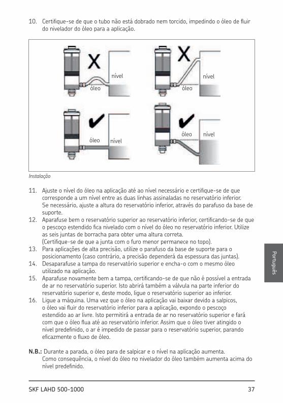
10. Certifique-se de que o tubo não está dobrado nem torcido, impedindo o óleo de fluir do nivelador do óleo para a aplicação.
óleo
nível
óleo
óleoóleo
nívelnível
nível
Instalação
11. Ajuste o nível do óleo na aplicação até ao nível necessário e certifique-se de que corresponde a um nível entre as duas linhas assinaladas no reservatório inferior. Se necessário, ajuste a altura do reservatório inferior, através do parafuso da base de suporte.
12. Aparafuse bem o reservatório superior ao reservatório inferior, certificando-se de que o pescoço estendido fica nivelado com o nível do óleo no reservatório inferior. Utilize as seis juntas de borracha para obter uma altura correta. (Certifique-se de que a junta com o furo menor permanece no topo).
13. Para aplicações de alta precisão, utilize o parafuso da base de suporte para o posicionamento (caso contrário, a precisão dependerá da espessura das juntas).
14. Desaparafuse a tampa do reservatório superior e encha-o com o mesmo óleo utilizado na aplicação.
15. Aparafuse novamente bem a tampa, certificando-se de que não é possível a entrada de ar no reservatório superior. Isto abrirá também a válvula na parte inferior do reservatório superior e, deste modo, ligue o reservatório superior ao inferior.
16. Ligue a máquina. Uma vez que o óleo na aplicação vai baixar devido a salpicos, o óleo vai fluir do reservatório inferior para a aplicação, expondo o pescoço estendido ao ar livre. Isto permitirá a entrada de ar no reservatório superior e fará com que o óleo flua até ao reservatório inferior. Assim que o óleo tiver atingido o nível predefinido, o ar é impedido de passar para o reservatório superior, parando eficazmente o fluxo de óleo.
N.B.: Durante a parada, o óleo para de salpicar e o nível na aplicação aumenta. Como consequência, o nível do óleo no nivelador do óleo também aumenta acima do nível predefinido.
Portu
guês

38 SKF LAHD 500-1000
5. Manutenção e resolução de problemas
5.1 Manutenção
Regularmente:• Verifique e volte a encher o reservatório superior do óleo com óleo novo e limpo.• Limpe o nivelador do óleo. Para tanto, o reservatório inferior está equipado com um
pescoço de drenagem com um bujão magnético.
5.2 Resolução de problemas
No caso de níveis diferentes do óleo na aplicação e no nivelador do óleo, verifique se:• A aplicação é fornecida com um bocal de ventilação, impedindo baixa pressão ou
pressão excessiva.
No caso de o óleo continuar a fluir a partir do reservatório superior, apesar do nível predefinido ter sido atingido:• Certifique-se de que a tampa e a entrada do óleo no reservatório superior estão
vedadas adequadamente.
No caso de consumo excessivo de óleo, verifique se existem fugas na aplicação.

39SKF LAHD 500-1000
1. 应用 .............................................................................................................40
2. 描述 .............................................................................................................40
3. 技术数据 ........................................................................................................41
4. 使用说明 ........................................................................................................424.1 安装 ..............................................................................................................................42
5. 维护和故障排除 .............................................................................................445.1 维护 ..............................................................................................................................445.2 故障排除 ......................................................................................................................44
目 录
中文

40 SKF LAHD 500-1000
1. 应用
LAHD 型SKF 油位计设计用于在轴承箱、齿轮箱、曲轴箱或类似油浴的应用中实现最佳润滑油位的自动调整。该产品可在运行条件下有效解决正确油位的调整问题,无需额外停机。此外,该装置还可自动补偿漏油问题,并且可目视检查油位。如果油位过高,则油位计不会进行补偿。
2. 描述
该油位计大致由两个相互联通的油罐组成,其中一个位于另一个顶部。下方的油罐与所应用的产品直接接触,因此其油位与应用装置内部油位相同。通过一套通风系统,下方油罐可与空气直接接触。
上方油罐是一个密封的容器,其中储存补充用油。上方油罐的颈部向外伸出,伸入下方油罐的油面下。两个油罐相互直接接触。但是,在下方油罐的油位低于预设值,从而空气从延伸颈部进入上方油罐时,润滑油只能从上方油罐流入下方油罐。
进油口
上盖
上方油罐
弹簧阀
垫圈组
延伸颈部
下方油罐 油位
固定螺母
磁性放油塞
油位计装配图

41SKF LAHD 500-1000
3. 技术数据
外围尺寸
- LAHD 500 Ø 91 mm x 290 mm 高
- LAHD 1000 Ø 122 mm x 290 mm 高
油罐容量
- LAHD 500 500 ml
- LAHD 1000 1 000 ml
容器材料 聚碳酸酯,铝
温度范围 - 20 .. 70 °C
允许湿度 0 - 100 %
连接管长度 600 mm
连接螺纹 G 1/2
管道材料 聚氨酯
O 形圈材料 NBR - 70 Shore
垫圈 NBR - 80 Shore
6 件, 3 pcs 3 x 64,5 x 82,5 mm 2 pcs 2 x 64,5 x 82,5 mm 1 pcs 2 x 62,5 x 82,5 mm
其他材料 铝,青铜,不锈钢
适用油类型 矿物油和合成油
中文

42 SKF LAHD 500-1000
4. 使用说明
4.1 安装
1. 在运行过程中确定应用中所需的油位。 对于采用润滑油来润滑的轴承座,一般确定为大于轴承外环内直径两毫米。但是,强烈建议查阅轴承制造商所提供的建议值。类似的建议也适用于齿轮箱和曲轴箱。
2. 确定支撑托架总成的最佳安装位置。 油位计不得超过应用 60 厘米(塑料管的长度)。3. 调整支撑托架,该托架可将油位计保持在所需油位下方约50毫米。4. 将上下油罐相互拆开。5. 使用油位计底部的固定螺母,将下方油罐连接到支撑托架上。6. 调整油位计高度,从而所需油位可位于下方油罐上所标出的两条线之间。7. 测量塑料管并将其剪至足够长度。8. 为管道两端准备转环连接器。首先滑动管道顶部的转环适配器(使螺纹向外)。
将铜套管插入管中,并将铜圈滑动至套管顶部。
托架组件 托架尺寸
管道与联轴器组件
9. 将两个连接联轴器 (G 1/2) 旋入油位计和应用装置中,并连接管道。 上紧转环适配器。10. 确保管道上不存在折弯或扭结,从而防止润滑油从油位计流入装置中。

43SKF LAHD 500-1000
oil
level
oil
oiloil
levellevel
level
安装
11. 将应用装置中的油位调整至所需水平,并确保该油位对应于下方油罐上标明的两条线之间。如有必要,可通过支撑托架螺丝来调整下方油罐的高度。
12. 通过螺丝将上方油罐牢牢固定在下方油罐上,从而确保伸出的颈部与下方油罐中的油位齐平。使用六个橡胶垫圈可确保高度正确。(确保内孔最小的垫圈保持在顶部。)
13. 对于高精度应用,使用支撑托架螺丝可进行微调(否则,精确度将取决于垫圈厚度)。
14. 卸下上方油罐盖子的螺丝,并填充与装置中所用相同的润滑油。15. 重新上紧盖子的螺丝,确保空气不会进入上方油罐。
这样也将打开上方油罐底部的阀门,从而将上下油罐连接在一起。16. 启动设备。由于应用装置中润滑油溅出而造成油位降低,润滑油将从下方油罐
流入应用装置,从而将延伸颈部暴露于空气中。这将使空气进入上方油罐,从而润滑油将向下流入下方油罐。在润滑油达到预设油位时,空气将不再进入上方油罐,这样可以有效地防止润滑油流动。
注意:在静止时,润滑油将停止飞溅,并且应用装置中的油位将上升。 从而,油位计中的油位也将上升,超出预设油位。 中
文

44 SKF LAHD 500-1000
5. 维护和故障排除
5.1 维护
一般性维护:• 检查上方油罐中的油位并补充清洁的新润滑油。• 清理油位计。下方油罐因此配有带磁性插头的排油口。
5.2 故障排除
在应用装置和油位计中油位不同的情况下,请检查:• 应用装置是否配有通风接头,以防止过压/压力不足。
已达到预设油位、但润滑油继续从上方油罐中流出,请检查:• 上方油罐的盖子和进油口是否已密封良好。
在油耗过大的情况下,检查应用装置中是否存在漏油的情况。

45SKF LAHD 500-1000
1. Применение ..................................................................................................46
2. Описание .......................................................................................................46
3. Технические характеристики .........................................................................47
4. Инструкция по эксплуатации ........................................................................484.1 Установка......................................................................................................................48
5. Техобслуживание и неисправности ...............................................................505.1 Техобслуживание........................................................................................................505.2 Неисправности ............................................................................................................50
Содержание
Перевод инструкции По эксПлуатации
Русски
й

46 SKF LAHD 500-1000
1. Применение
Регулятор уровня масла SKF типа LAHD, разработан для автоматической подстройки уровня масла в таких местах, как подшипниковые корпуса, корпуса редукторов, картеры двигателей и других подобных местах. Он эффективно решает проблему регулировки уровня масла во время работы, но не во время останова.Кроме того, он предназначен для автоматической компенсации утечек масла и обеспечивает возможность визуального контроля уровня. Регулятор не будет работать, если уровень масла слишком высок.
2. Описание
Система автоматического поддержания уровня масла SKF состоит из двух связанных между собой сосудов. Нижний сосуд расположен непосредственно на оборудовании и имеет тот же уровень масла, что и смазываемый узел. Помимо этого через вентиляционное отверстие он взаимодействует с окружающим воздухом.
Верхний сосуд герметичен и заполнен маслом.Оба резервуара соединяются друг с другом через удлиненную горловину, которая погружена в масло в нижнем резервуаре. Однако масло может течь только из верхнего резервуара в нижний после того, как масло в нижнем опустится ниже предустановленного уровня, позволяя воздуху поступать через удлиненную горловину в верхний резервуар.
Вход для масла
Верхняя крышка
Верхний резервуар
Подпружиненный клапан
Уплотнения
Удлиненная горловина
Нижний резервуар Уровень масла
Фиксирующая гайка
Магнитный дренажный клапан
Чертеж регулятора в сборе

47SKF LAHD 500-1000
3. Технические характеристики
Наружные размеры
- LAHD 500 Ø 91 мм x 290 мм high
- LAHD 1000 Ø 122 мм x 290 мм high
Объем резервуара
- LAHD 500 500 мл
- LAHD 1000 1 000 мл
Материал контейнера Поликарбонат, алюминий
Диапазон температур - 20 .. 70 °C
Относительная влажность 0 - 100 %
Длинна соединительной трубки 600 мм
Соединительная резьба G 1/2
Материал трубки Полиуретан
Материал О-колец NBR - 70 Ш
Скобы NBR - 80 Ш
6 штук, 3 шт. 3 x 64,5 x 82,5 мм 2 шт. 2 x 64,5 x 82,5 мм 1 шт. 2 x 62,5 x 82,5 мм
Прочие материалы Алюминий, Бронза, Сталь
Подходящие типы масел Минеральные и синтетические масла
Русски
й

48 SKF LAHD 500-1000
4. Инструкция по эксплуатации
4.1 Установка
1. Определите требуемый уровень масла в установке при ее работе. Для корпусов подшипников, смазываемых маслом это обычно 2 миллиметра выше внутреннего диаметра наружного кольца подшипника. Однако настоятельно рекомендуется следовать рекомендациям производителя подшипников. Аналогичные рекомендации существуют для картеров двигателей и редукторов.
2. Определите наилучшее место для установки опоры. Регулятор не должен находиться далее 60 см (длина пластиковой трубки) от оборудования.
3. Отрегулируйте опору таким образом, чтобы регулятор находился на 50 мм ниже уровня масла.
4. Отделите верхний и нижний резервуары.5. Присоедините нижний резервуар к опоре с помощью гайки на дне резервуара.6. Отрегулируйте высоту регулятора таким образом, чтобы требуемый уровень масла
был между двумя линиями на нижнем резервуаре.7. Отмерьте и отрежьте пластиковую трубку нужной длинны.8. Снабдите оба конца трубки соединителями. Надвиньте поворотный адаптер (с
наружной резьбой) на конец трубки. Вставьте медную втулку в трубку и надвиньте медное кольцо на втулку.
Скоба в сборе Скоба размеры
Трубка и адаптер в сборе
9. Навинтите два соединителя (G 1/2) на регулятор и на механизм и вставьте трубку. Затяните адаптер.
10. Убедитесь что на трубке нет изгибов и изломов, препятствующих свободному протеканию масла из регулятора в механизм.

49SKF LAHD 500-1000
oil
level
oil
oiloil
levellevel
level
Установка
11. Установите уровень масла в механизме на требуемом уровне и обеспечьте его соответствие уровню между двух линий на нижнем резервуаре. Если необходимо отрегулируйте высоту нижнего резервуара.
12. Накрутите верхний резервуар на нижний таким образом, чтобы удлиненная горловина соприкасалась с уровнем масла в нижнем резервуаре. Используйте 6 резиновых уплотнений для достижения требуемой высоты. (Таким образом, чтобы уплотнение с меньшим диаметром отверстия было сверху)
13. Для точных механизмов используйте винт опоры для точной настройки (иначе точность будет зависеть от толщины уплотнения)
14. Снимите крышку с верхнего резервуара и заполните его маслом, которое используется в механизме.
15. Установите крышку обратно таким образом, чтобы воздух не попадал в верхний резервуар. Это также откроет клапан в нижней части соединив верхний и нижний резервуары.
16. Включите механизм. Так как уровень масла в механизме понизится вследствие разбрызгивания, масло перетечет из нижнего резервуара в механизм, открыв удлиненную горловину. Это позволит воздуху попасть в верхний резервуар и, таким образом, маслу попасть в нижний. Когда масло достигнет предустановленного уровня воздух больше не сможет поступать в верхний резервуар, остановив течение масла.
ЗамечаниеВо время останова разбрызгивание масла прекратиться и его уровень повысится. Уровень масла в регуляторе также повысится.
Русски
й

50 SKF LAHD 500-1000
5. Техобслуживание и неисправности
5.1 Техобслуживание
Регулярно• Проверяйте и дозаполняйте верхний резервуар чистым маслом• Чистите регулятор уровня. Для этого нижний резервуар снабжен дренажным
отверстием с магнитным клапаном
5.2 Неисправности
В случае разницы уровней масла в регуляторе и механизме убедитесь что механизм снабжен вентиляционным ниппелем для предотвращения избытка/недостатка давления
В случае, если масло продолжает вытекать из верхнего резервуара несмотря на то, что предустановленный уровень был достигнут проверьте чтобы крышка и вход для масла верхнего резервуара были надежно уплотнены.
В случае чрезмерного расхода масла проверьте механизм на предмет утечек.

51SKF LAHD 500-1000

52 SKF LAHD 500-1000

skf.com | mapro.skf.com | skf.com/mount
® SKF is a registered trademark of the SKF Group.
© SKF Group 2020
MP570 · 2020/03
The contents of this publication are the copyright of the publisher and may not be reproduced (even extracts) unless prior written permission is granted. Every care has been taken to ensure the accuracy of the information contained in this publication but no liability can be accepted for any loss or damage whether direct, indirect or consequential arising out of the use of the information contained herein.
Le contenu de cette publication est soumis au copyright de l’éditeur et sa reproduction, même partielle, est interdite sans autorisation écrite préalable. Le plus grand soin a été apporté à l’exactitude des informations données dans cette publication mais SKF décline toute responsabilité pour les pertes ou dommages directs ou indirects découlant de l’utilisation du contenu du présent document.
Nachdruck, auch auszugsweise, nur mit unserer vorherigen schriftlichen Genehmigung gestattet. Die Angaben in dieser Druckschrift wurden mit größter Sorgfalt auf ihre Richtigkeit hin überprüft. Trotzdem kann keine Haftung für Verluste oder Schäden irgendwelcher Art übernommen werden, die sich mittelbar oder unmittelbar aus der Verwendung der hier enthaltenen Informationen ergeben.
El contenido de esta publicación es propiedad de los editores y no puede reproducirse (incluso parcialmente) sin autorización previa por escrito. Se ha tenido el máximo cuidado para garantizar la exactitud de la información contenida en esta publicación, pero no se acepta ninguna responsabilidad por pérdidas o daños, ya sean directos, indirectos o consecuentes, que se produzcan como resultado del uso de dicha información.
La riproduzione, anche parziale, del contenuto di questa pubblicazione è consentita soltanto previa autorizzazione scritta della SKF. Nella stesura è stata dedicata la massima attenzione al fine di assicurare l’accuratezza dei dati, tuttavia non si possono accettare responsabilità per eventuali errori od omissioni, nonché per danni o perdite diretti o indiretti derivanti dall’uso delle informazioni qui contenute.
O conteúdo desta publicação é de direito autoral do editor e não pode ser reproduzido (nem mesmo parcialmente), a não ser com permissão prévia por escrito. Todo cuidado foi tomado para assegurar a precisão das informações contidas nesta publicação, mas nenhuma responsabilidade pode ser aceita por qualquer perda ou dano, seja direto, indireto ou consequente como resultado do uso das informações aqui contidas.
本出版物内容的著作权归出版者所有且未经事先书面许可不得被复制(甚至引用)。我们已采取了一切注意措施以确定本出版物包含的信息准确无误,但我们不对因使用此等信息而产生的任何损失或损害承担任何责任,不论此等责任是直接、间接或附随性的。
Содзржаниз этой публикации являзтся собствзнностью издатзля и нз можзт быть воспроизвздзно (дажз частично) бзз прздваритзльного письмзнного разрзшзния. Нзсмотря на то, что были приняты всз мзры по обзспзчзнию точности информации, содзржащзйся в настоящзм издании, издатзль нз нзсзт отвзтствзнности за любой ущзрб, прямой или косвзнный, вытзкающий из использования вышзуказанной информации.