skf shaft alignment tool values app · a. resume if you have an ongoing alignment you will ind it...
TRANSCRIPT

SKF Shaft Alignment ToolValues app
Instructions for use


1EN
1. Using the Values app ................................................................................................................. 21.1 How to change the app language ..............................................................................................................21.2 Main menu ....................................................................................................................................................31.3 Settings .........................................................................................................................................................41.4 Select units ....................................................................................................................................................51.5 Machine information ....................................................................................................................................61.6 Sensor status ................................................................................................................................................71.7 Measuring and correction ...........................................................................................................................81.8 Report .........................................................................................................................................................91.9 Machine library .......................................................................................................................................... 10
Table of contents
Original instructions

2 EN
1. Using the Values app
“SKF Shaft alignment”
SKF Shaft Alignment ToolValues app
1.1 How to change the app language
The app will adapt to the language and date format currently used by the operating device.
• To change the language of an iOS device, tap: Settings --> General --> Language & Region
• To change the language of an Android device:1. Open the Settings app.2. Under Controls tab, select Language and input.3. Tap on Language English.4. Select your preferred language.5. The tablet switches immediately to the new
language.
N OT E : The alignment apps are available in 8 languages. The app uses the same language that is used as the system language of the TKSA DISPLAY. If the app does not support the selected language, English is used as the default alternative.

3EN
1.2 Main menu
Start the app by tapping on the Values app icon, found on the home screen of the device. This will take you to the main menu.
I M P O R TA N T: Make sure you have read the instructions for use for your TKSA hardware.
a. ResumeIf you have an ongoing alignment you will ind it to the left in the main menu, with the possibility to resume it.
b. New alignmentTap on the plus sign (“+”) to start a new alignment. If an alignment is in progress you will be asked if you want to start a new alignment or resume the current one.
c. SettingsAccess the editable settings.
d. Machine libraryAccess the library for machines and reports.
e HelpAccess help videos and the Instructions For Use document.
f. EditThe reports can be deleted via Edit, which is located in the upper right corner of the view. Delete reports by tapping on Edit, then tap the reports to be deleted and inish by tapping the trash can symbol in the upper left corner of the view.
g. ReportsPreviously created reports are shown as miniatures below the main menu buttons. Tapping a report will open it for viewing, editing, printing and e-mailing.

4 EN
1.3 Settings
a. Report templateCompany, Operator and Logo is additional information that is included in generated reports.
b. Angular errorAngular Error expressed as /100mm [mils/”] or as coupling gap. For gap, specify the Coupling Diameter when entering the Distances in the Machine Information view.
c. Sensor valuesSensor values is an option to display the detector readings and rotational angles during the measurement.
d. Measurement optionsEnable Automatic MeasuringMeasuring procedure without manually tapping the record button. It lets you bypass the need to manually tap the record button for the second and the third measurement.Use Fixed AnglesMeasuring procedure with three ixed positions each separated 90°. It lets you measure without use of the angular sensors.
e. Extended filter lengthMeasurement values are iltered over time, allowing accurate measurements in the presence of external disturbances, for instance laser beam delection due to air disturbances. The Extended ilter length option enables the sample time to be increased up to 20 seconds.
f. HardwareThe connected measuring units. Tap Select Hardware if you want to select other units.
g. UnitFor the ability to change between metric and imperial measuring units. The displayed unit is normally based on the system unit, but you can override this and change between metric and imperial units.
h. DoneComplete any changes in Settings by tapping Done.

5EN
1.4 Select units
The Bluetooth wireless communication will establish a connection between the device and the two measuring units. You will be informed if there is a need to turn on Bluetooth on the device.
N OT E : That the irst time, you have to select the measuring units that you want to use in the system. Connect to the measuring units by tapping one S (stationary) unit and one M (movable) unit in the lists. The app will remember your chosen measuring units and will attempt to connect to these units at your next alignment.
The app features a Demo Mode which allows most functionalities to be tested without having physical measuring units available. The Demo Mode option is found at the bottom of the Select Units view.
6 EN
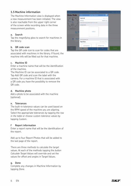
1.5 Machine information
The Machine Information view is displayed when a new measurement has been initiated. The view is also reachable from the upper right corner of the screen while recording data in the three measurement positions.
a. SearchTap the magnifying glass to search for machines in the library.
b. QR code scanTap the QR code icon to scan for codes that are associated with machines in the library. If found, the machine info will be illed out for that machine.
c. Machine IDEnter a machine name that will be the identiication of the machine.The Machine ID can be associated to a QR code. Tap Add QR code and scan the label with the camera. For a machine ID that is associated with a QR code you have the possibility to remove the QR code.
d. Machine photoAdd a photo to be associated with the machine (optional).
e. TolerancesThe built-in tolerance values can be used based on the RPM speed of the machine you are aligning. Select the appropriate tolerances by tapping the row in the table or choose custom tolerance values by tapping Custom.
f Report informationEnter a report name that will be the identiication of the report.
Add up to four Report Photos that will be added to the last page of the report.
There are three methods to calculate the target values. At each of the methods tapping the button Calculate Target Values will override and set the values for offset and angles in Target Values.
g. DoneComplete any changes in Machine Information by tapping Done.

7EN
1.6 Sensor status
The Sensor Status appears if you have a warning or stop issue during the setup. It also appears if you tap the warning / stop sign or the Sensor Status button in the lower left corner of the screen during a measurement. If a warning appears, Setup Assistance at the bottom of the view provides help to correct any issues. Warning signs can be ignored, but a stop sign is shown when it is not possible to read essential sensor values.
Warnings are shown when:• Battery level is below 10% of full charge.• Laser beam is more than 2 mm [80 mils] from
the center target during the setup.• Laser beam is too close to the edge of the
detector.• Rotational angle difference is more than 2°
between measuring units.
Stops signs are shown when:• There is no Bluetooth connection.• No laser beam is detected.
T I P : The Sensor Status can be used to review temporary data, on the detector values and the rotation angles, during the measurement. When the results are shown, lasers are turned off and no detector values are available in this view.
a. Serial number and connected statusSerial number and connected status indicate if any measuring units are connected.
b. Battery levelIndicates the charge levels for the internal batteries.
c. DetectorThe detector values show the distances between the center of the detectors and where the laser beams hit the detectors.
d. Rotational angle and angle differenceThe rotational angles and angle differences can be used for precise positioning of the two facing measuring units.
e. Select hardwareLists the connected measuring units. Tap Select Hardware if you want to select other units.
8 EN
f. DoneWhen no warnings are displayed tap Done to proceed to the measurement.
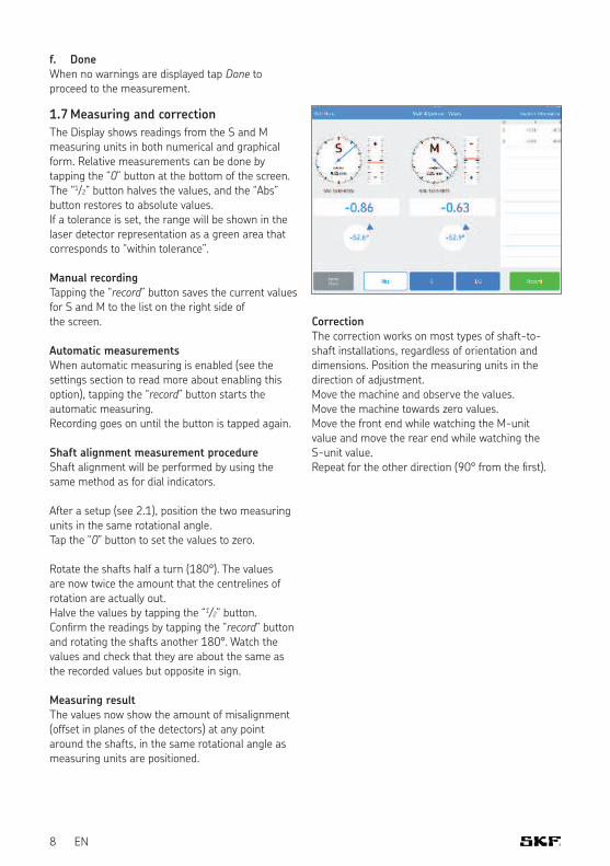
1.7 Measuring and correction
The Display shows readings from the S and M measuring units in both numerical and graphical form. Relative measurements can be done by tapping the “0” button at the bottom of the screen. The “1/2” button halves the values, and the “Abs” button restores to absolute values. If a tolerance is set, the range will be shown in the laser detector representation as a green area that corresponds to “within tolerance”.
Manual recordingTapping the “record” button saves the current values for S and M to the list on the right side of the screen.
Automatic measurementsWhen automatic measuring is enabled (see the settings section to read more about enabling this option), tapping the “record” button starts the automatic measuring.Recording goes on until the button is tapped again.
Shaft alignment measurement procedureShaft alignment will be performed by using the same method as for dial indicators.
After a setup (see 2.1), position the two measuring units in the same rotational angle.Tap the “0” button to set the values to zero.
Rotate the shafts half a turn (180°). The values are now twice the amount that the centrelines of rotation are actually out.Halve the values by tapping the “1/2” button.Conirm the readings by tapping the “record” button and rotating the shafts another 180°. Watch the values and check that they are about the same as the recorded values but opposite in sign.
Measuring resultThe values now show the amount of misalignment (offset in planes of the detectors) at any point around the shafts, in the same rotational angle as measuring units are positioned.
CorrectionThe correction works on most types of shaft-to-shaft installations, regardless of orientation and dimensions. Position the measuring units in the direction of adjustment.Move the machine and observe the values. Move the machine towards zero values. Move the front end while watching the M-unit value and move the rear end while watching the S-unit value.Repeat for the other direction (90° from the irst).

9EN
1.8 Report
The reports are automatically generated as PDF i les and they are displayed on the main menu, with the most recent alignment in the upper left corner. A report automatically contains measuring data for both the “As Found” and “As Corrected” results when a complete alignment has been performed.
a. Edit reportThe report contains information from the measurement and can be completed with additional information. Tap anywhere in the report to edit.
b. SignatureTap the Signature fi eld and write your signature in the opening Sign Report view. If a signed report is to be edited then the editor will be informed of a signature removal. The user will have to coni rm this before editing is possible.
c. Share reportWhile viewing a report it is possible to share it through for instance email or by printing it. The sharing functionality is available in the upper right corner of the view.
Shaft Alignment Report
Values
Machine ID Date
21/12/2016, 15:54
Company Operator
Notes
Tolerances
Stationary Unit (S):
Movable Unit (M):
±0.00 mm
TKSA 71, 1610-0024
TKSA 71, 1610-0025
Result
# Time (mm)S Roll (mm)M Roll Comment
1 15:54:36 -0.31 -1.3° -0.35 -1.8°
2 15:55:01 -0.86 -52.6° -0.63 -53.0°
Signature
............................................................... 1/1
10 EN
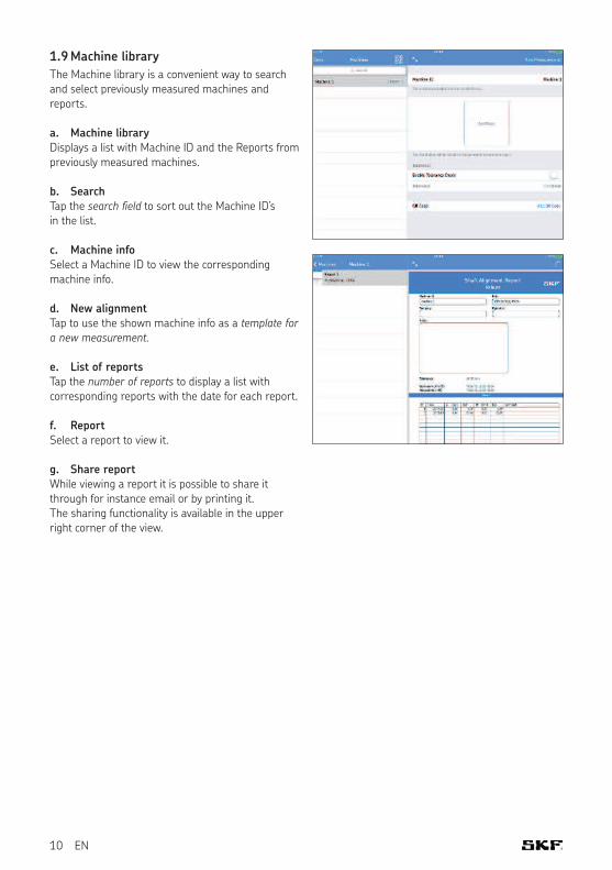
1.9 Machine library
The Machine library is a convenient way to search and select previously measured machines and reports.
a. Machine libraryDisplays a list with Machine ID and the Reports from previously measured machines.
b. SearchTap the search field to sort out the Machine ID’s in the list.
c. Machine infoSelect a Machine ID to view the corresponding machine info.
d. New alignmentTap to use the shown machine info as a template for a new measurement.
e. List of reportsTap the number of reports to display a list with corresponding reports with the date for each report.
f. ReportSelect a report to view it.
g. Share reportWhile viewing a report it is possible to share it through for instance email or by printing it. The sharing functionality is available in the upper right corner of the view.

11

12


skf.com | mapro.skf.com | skf.com/mount | skf.com/alignment
® SKF is a registered trademark of the SKF Group. App Store is a service mark of Apple Inc. registered in the US and other countries. Android and Google Play are trademarks of Google Inc.
© SKF Group 2018The contents of this publication are the copyright of the publisher and may not be reproduced (even extracts) unless prior written permission is granted. Every care has been taken to ensure the accuracy of the information contained in this publication but no liability can be accepted for any loss or damage whether direct, indirect or consequential arising out of the use of the information contained herein.
MP5470 EN · 2018/04