skid steers
TRANSCRIPT
Learning Goals
• To safely use a skid steer loader
Related Task Sheets:
Hazard Warning Signs 2.8
Hand Signals 2.9
Mechanical Hazards 3.1
Tractor Hazards 4.2
Preventative Maintenance and Pre-Operation Checks
4.6
Starting and Stopping Diesel and Gasoline Engines
4.7
Tractor Stability 4.12
Using the Tractor Safely 4.13
Using Implements With Hydraulic Components
5.5
Noise Hazards and Hearing Protection
3.2
Skid steer loaders are versatile
machines. They fit into small
spaces, can turn within a tight
radius, and are easy to operate.
Young farm workers can enjoy
much work success with the skid
steer loader.
This task sheet discusses the safe
use of a skid steer loader. Skid
steer loaders are safe to use if the
operator works within the
machine’s limitations. As in all
machinery use, the operator must
know the machine’s proper use, as
well as its limitations.
Skid Steer Loader
Basics Hydraulic Power
A skid steer loader is a hydraulic
workhorse. A hydrostatic
transmission controls forward and
reverse direction. Hydrostatic
valves control the flow of
hydraulic oil to steer the machine
by “skidding” it sharply around
corners. Hydraulic cylinders raise
and lower lift arms and tilt the load
bucket. Task Sheet 5.5 serves as a
review of hydraulic power.
Hydraulic power is positive power.
The machine moves the instant you
move the hydraulic control levers
or pedals. The skid steer will move
forward, reverse, or “skid” steer.
The load bucket will lift, roll or tilt.
Bumping the control levers can
cause the machine to move
unintentionally.
Introduction
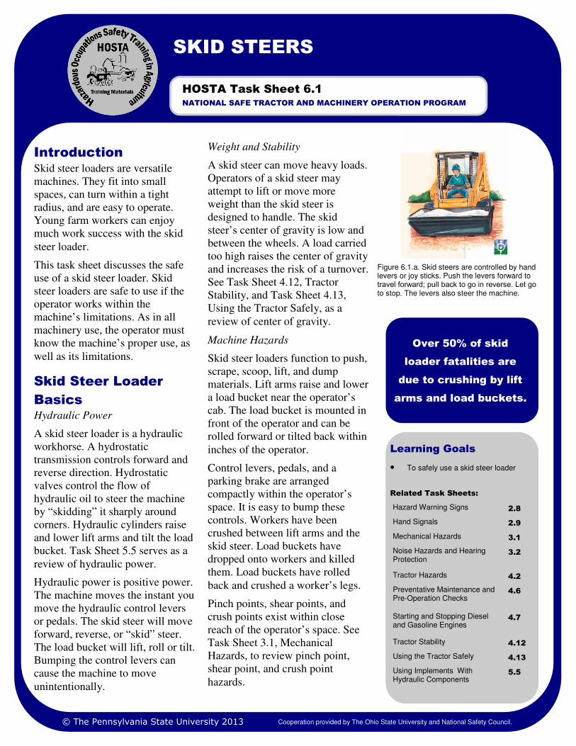
Figure 6.1.a. Skid steers are controlled by hand levers or joy sticks. Push the levers forward to travel forward; pull back to go in reverse. Let go to stop. The levers also steer the machine.
Over 50% of skid
loader fatalities are
due to crushing by lift
arms and load buckets.
SKID STEERS
NATIONAL SAFE TRACTOR AND MACHINERY OPERATION PROGRAM
HOSTA Task Sheet 6.1
Weight and Stability
A skid steer can move heavy loads.
Operators of a skid steer may
attempt to lift or move more
weight than the skid steer is
designed to handle. The skid
steer’s center of gravity is low and
between the wheels. A load carried
too high raises the center of gravity
and increases the risk of a turnover.
See Task Sheet 4.12, Tractor
Stability, and Task Sheet 4.13,
Using the Tractor Safely, as a
review of center of gravity.
Machine Hazards
Skid steer loaders function to push,
scrape, scoop, lift, and dump
materials. Lift arms raise and lower
a load bucket near the operator’s
cab. The load bucket is mounted in
front of the operator and can be
rolled forward or tilted back within
inches of the operator.
Control levers, pedals, and a
parking brake are arranged
compactly within the operator’s
space. It is easy to bump these
controls. Workers have been
crushed between lift arms and the
skid steer. Load buckets have
dropped onto workers and killed
them. Load buckets have rolled
back and crushed a worker’s legs.
Pinch points, shear points, and
crush points exist within close
reach of the operator’s space. See
Task Sheet 3.1, Mechanical
Hazards, to review pinch point,
shear point, and crush point
hazards.
© The Pennsylvania State University 2013 Cooperation provided by The Ohio State University and National Safety Council.
Page 2 SKID STEERS
bars (hand holds) and the tread
plates mounted on the load bucket.
A three-point hold provides the
safest footing. The load bucket and
machine surfaces can be slippery
when wet or muddy. Exit from the
machine in the same manner.
When seated, lower the restraint
bar and/or fasten the seat belt
immediately.
Controls
Before using the skid steer,
become familiar with the controls.
A qualified person should
demonstrate how to start and stop
the engine, how to move the
machine forward and reverse, how
to steer the skid steer, and how to
raise, lower, and tilt the bucket
attachment. It is a good idea to
know how to safely change
attachments. If an attachment to
the skid steer uses hydraulic
power, ask for a demonstration of
how to engage the remote
hydraulic unit.
Skid steer loaders are controlled by
hand levers and foot pedals. The
beginning operator should
Preventative maintenance
Before using the skid steer,
complete a maintenance inspection
of the machine. Check the oil level,
tire pressure, coolant level, and
fuel. See Task Sheet 4.6 to review
similar items to check on a tractor.
Entering and exiting the skid steer
Before entering the machine,
observe the following points.
• Lift arms and bucket should be
completely lowered. Do not
reach into the cab from the
ground level to move hydraulic
levers or pedals to position the
lift arms and bucket. Crushing
can result.
• The seat and floor should be
clear of obstructions. Objects
can roll beneath foot control
pedals and interfere with the
machine’s operation.
To enter the skid steer, use the grab
Operating the Skid
Steer Loader
Use both
hands and
both feet to
control the
skid steer’s
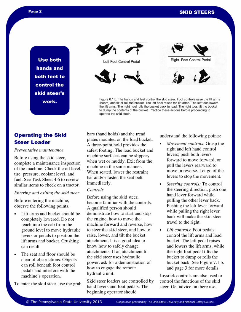
work. Figure 6.1.b. The hands and feet control the skid steer. Foot controls raise the lift arms (boom) and tilt or roll the bucket. The left heel raises the lift arms. The left toes lowers the lift arms. The right heel rolls the bucket back to load. The right toes tilt the bucket to dump the contents of the bucket. Practice these actions before proceeding to operate the skid steer.
understand the following points:
• Movement controls: Grasp the
right and left hand control
levers; push both levers
forward to move forward, or
pull the levers rearward to
move in reverse. Let go of the
levers to stop the movement.
• Steering controls: To control
the steering direction, push one
hand lever forward while
pulling the other lever back.
Pushing the left lever forward
while pulling the right lever
back will make the skid steer
travel to the right.
• Lift controls: Foot pedals
control the lift arms and load
bucket. The left pedal raises
and lowers the lift arms, while
the right foot pedal tilts the
bucket to dump or rolls the
bucket back. See Figure 7.1.b.
and page 3 for more details.
Joystick controls are also used to
control the functions of the skid
steer. Get advice on there use.
Right Foot Control Pedal Left Foot Control Pedal
© The Pennsylvania State University 2013 Cooperation provided by The Ohio State University and National Safety Council.
Page 3 HOSTA TASK SHEET 6.1
Foot pedals on the skid steer are
used to control the high lift (boom)
work of the skid steer. Toe and
heel movements are needed to
activate these controls. See Figure
7.1.b. Note: Some models use the
hand controls to make these
movements.
Raising the lift arms (left pedal):
The left pedal raises or lowers the
lift arm (boom). Use the left heel to
push on the back of the pedal to
raise the lift arms and bucket. Use
the left toes to push on the front of
the pedal to lower the bucket.
These movements must be done
smoothly. Hard-soled shoes give
better feel for the pressure needed
on the pedal.
Tilting the bucket (right pedal):
The right pedal controls the load
bucket. Use the right heel to push
on the back of the pedal to roll the
bucket back while loading. Use the
right toes to push on the front of
the pedal to dump the bucket while
unloading.
bystanders, pets, and farm animals
• Do not work near overhead utility lines.
• Lower the load bucket for trav-el.
• Use slower speeds over rough ground
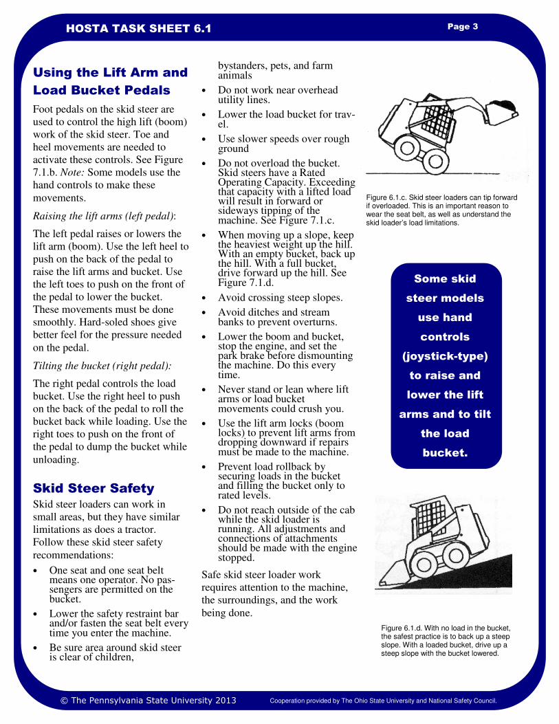
• Do not overload the bucket. Skid steers have a Rated Operating Capacity. Exceeding that capacity with a lifted load will result in forward or sideways tipping of the machine. See Figure 7.1.c.
• When moving up a slope, keep the heaviest weight up the hill. With an empty bucket, back up the hill. With a full bucket, drive forward up the hill. See Figure 7.1.d.
• Avoid crossing steep slopes.
• Avoid ditches and stream banks to prevent overturns.
• Lower the boom and bucket, stop the engine, and set the park brake before dismounting the machine. Do this every time.
• Never stand or lean where lift arms or load bucket movements could crush you.
• Use the lift arm locks (boom locks) to prevent lift arms from dropping downward if repairs must be made to the machine.
• Prevent load rollback by securing loads in the bucket and filling the bucket only to rated levels.
• Do not reach outside of the cab while the skid loader is running. All adjustments and connections of attachments should be made with the engine stopped.
Safe skid steer loader work
requires attention to the machine,
the surroundings, and the work
being done.
Skid steer loaders can work in
small areas, but they have similar
limitations as does a tractor.
Follow these skid steer safety
recommendations:
• One seat and one seat belt means one operator. No pas-sengers are permitted on the bucket.
• Lower the safety restraint bar and/or fasten the seat belt every time you enter the machine.
• Be sure area around skid steer is clear of children,
Using the Lift Arm and
Load Bucket Pedals
Skid Steer Safety
Some skid
steer models
use hand
controls
(joystick-type)
to raise and
lower the lift
arms and to tilt
the load
bucket.
Figure 6.1.c. Skid steer loaders can tip forward if overloaded. This is an important reason to wear the seat belt, as well as understand the skid loader’s load limitations.
Figure 6.1.d. With no load in the bucket, the safest practice is to back up a steep slope. With a loaded bucket, drive up a steep slope with the bucket lowered.
© The Pennsylvania State University 2013 Cooperation provided by The Ohio State University and National Safety Council.
1. Safety Management for Landscapers, Grounds-Care Businesses, and Golf Courses, 2001, First Edition, John Deere Publishing, Moline, Illinois.
2. www.cdc.gov/niosh/nasd/Click on search by top-ic/Scroll to Skid Steer.
3. www.cdc.gov/niosh/At search box, type Preventing Injuries and Deaths from Skid Steer Loaders.
References
Page 4 SKID STEERS
1. Use the Internet to visit manufacturers’ websites (John Deere, New Holland, Bobcat, etc). Assemble a
picture chart of as many skid steer loader attachments as you can find.
2. Set up a skid steer loader course to practice moving the skid steer around and through obstacles. Be sure that
one part of the obstacle course involves using the load bucket.
3. With adult supervision and a blind fold (skid steer parked and brakes locked), raise and lower the lift
(boom) arms and tilt and roll the bucket as the supervisor commands you. You must be able to use the prop-
er controls to operate the skid steer without errors.
4. Matching. Match the skid steer control position with the resulting action to be expected.
Skid steer control position Resulting action to be expected
_____A. Left foot pedal pushed forward with toes 1. Skid steer spins in circles to the left
_____B. Left foot pedal pushed downward with heel 2. Lift arm raises
_____C. Right foot pedal pushed forward with toes 3. Bucket tilts forward to unload
_____D. Right foot pedal pushed downward with heel 4. Bucket rolls back to load
_____E. Right hand control lever pushed fully forward,
left hand control lever pulled fully back 5. Lift arm lowers
_____F. Right hand control lever pulled backward,
left hand control lever pulled back 6. Skid steer moves forward
7. Skid steer moves in reverse
5. Determine how the joystick controlled skid steer performs the functions in Question 4.
Safety Activities
National Safe Tractor and Machinery Operation Program The Pennsylvania State University Agricultural and Biological Engineering Department 246 Agricultural Engineering Building University Park, PA 16802 Phone: 814-865-7685 Fax: 814-863-1031 Email: [email protected]
Contact Information
Developed, written and edited by WC Harshman, AM Yoder, JW Hilton and D J Murphy, The Pennsylvania State University. Reviewed by TL Bean and D Jepsen, The Ohio State University and S Steel, National Safety Council. Revised 3/2013
This material is based upon work supported by the National Institute of Food and Agriculture, U.S. Department of Agriculture, under Agreement Nos. 2001-41521-01263 and 2010-41521-20839. Any opinions, findings, conclusions, or recommendations expressed in this publication are those of the author(s) and do not necessarily reflect the view of the U.S. Department of Agriculture.
Credits
© The Pennsylvania State University 2013 Cooperation provided by The Ohio State University and National Safety Council.
STARTING AND STOPPING A SKID
STEER
Learning Goals
• To be able to safely start and stop the
skid steer
Don’t be surprised if you can’t just
jump on the skid steer, turn the key
and be gone. Skid steer
manufacturer’s safety decals warn
that operators must have
instruction before running the
machine. Ask questions; get
training; read the Operator’s
Manual; don’t just tell the
supervisor you know what to do.
Untrained operators can cause
injury, fatality, and property
damage.
This task sheet will help you to
understand how to safely start and
stop a skid steer.
Interlock Control
System
Skid steers are equipped with an
interlock system meaning the skid
steer cannot be started unless the
operator is physically in position to
operate the machine. The machine
cannot be started and operated
except from the seat and with the
seat belt fastened.
The seat belt and the operator
restraint allow the lift, tilt, and
traction functions of the skid steer
to be activated. All of these
functions are electronically
interlocked with the start function.
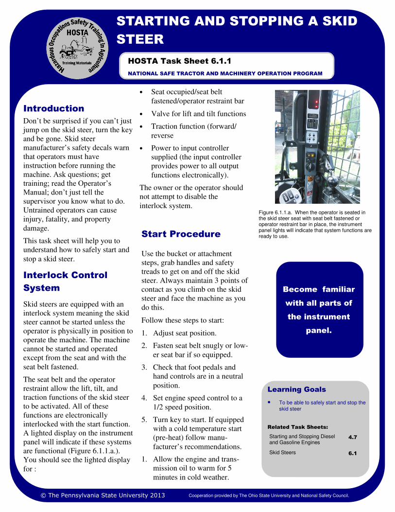
A lighted display on the instrument
panel will indicate if these systems
are functional (Figure 6.1.1.a.).
You should see the lighted display
for :
• Seat occupied/seat belt
fastened/operator restraint bar
• Valve for lift and tilt functions
• Traction function (forward/
reverse
• Power to input controller
supplied (the input controller
provides power to all output
functions electronically).
The owner or the operator should
not attempt to disable the
interlock system.
Introduction
Figure 6.1.1.a. When the operator is seated in the skid steer seat with seat belt fastened or operator restraint bar in place, the instrument panel lights will indicate that system functions are ready to use.
Become familiar
with all parts of
the instrument
panel.
NATIONAL SAFE TRACTOR AND MACHINERY OPERATION PROGRAM
HOSTA Task Sheet 6.1.1
Related Task Sheets:
Starting and Stopping Diesel and Gasoline Engines
4.7
Skid Steers 6.1
© The Pennsylvania State University 2013 Cooperation provided by The Ohio State University and National Safety Council.
Start Procedure
Use the bucket or attachment
steps, grab handles and safety
treads to get on and off the skid
steer. Always maintain 3 points of
contact as you climb on the skid
steer and face the machine as you
do this.
Follow these steps to start:
1. Adjust seat position.
2. Fasten seat belt snugly or low-
er seat bar if so equipped.
3. Check that foot pedals and
hand controls are in a neutral
position.
4. Set engine speed control to a
1/2 speed position.
5. Turn key to start. If equipped
with a cold temperature start
(pre-heat) follow manu-
facturer’s recommendations.
1. Allow the engine and trans-
mission oil to warm for 5
minutes in cold weather.
Page 2 STARTING AND STOPPING A SKID STEER
1. Various Skid Steer Manufacturer’s Operation and Maintenance Manuals
2. Website, www.agsafety.psu.edu. Scroll to Publications, E47 Skid-Steer Safety for Farm and Landscape, Dennis J. Murphy and William Harshman
3. Safety Management for Landscapers, Grounds-Care Businesses and Golf Courses, 2001, First Edition, John Deere Publishing, Moline, Illinois
References
1. If you have never operated a skid steer, visit an equipment dealership and ask to sit in the skid steer cab to
observe what controls are available and where they are located. This may be done with your employer’s
guidance as well.
2. Use the operator’s manual for the skid steer you will operate to study the controls and instrument gauges as
you sit in the operator’s position.
3. Practice starting and shutting off the skid steer and using the lift and traction controls while sitting in the
machine with the parking brake set.
4. Learn where the lift arm locking pins are located on the skid steer.
5. Ask a classmate to describe the conditions that must be met for an operator to exit the skid steer cab.
Safety Activities
See Figure 2
4. If attachments with hydraulic
hoses are to be changed, relieve
the pressure in the auxiliary
hydraulic system either by
turning the ignition key past
stop for a few seconds until the
engine is stopped, or by
moving the hydraulic control
lever back and forth several
times after the engine is
stopped. This will make the use
of the Quick Couplers® easier
to disconnect and connect.
5. Turn the ignition key to off if
not already completed.
6. Remove key if required.
7. Raise seat bar or remove seat
belt, and dismount the machine
using the grab handles while
facing the machine. Maintain
3-points of contact as you exit
the machine.
Stopping the engine may not be as
simple as turning off the ignition
key. Some manufacturers may
instruct the user to let the machine
idle for a few minutes to cool the
engine, hydraulics, and hydrostatic
transmission fluid. Become
familiar with what each machine
requires for shut down. Your
supervisor should have this
information readily available.
To stop the skid steer:
1. Idle back the engine speed to
1/2 throttle .
2. Set the parking brake.
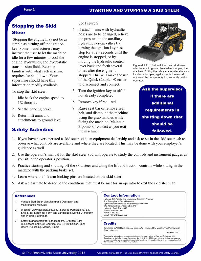
3. Return lift arms and
attachments to ground level.
Stopping the Skid
Steer
Ask the supervisor
if there are
additional
requirements in
shutting down that
should be
followed.
Figure 6.1.1.b.. Return lift arm and skid steer attachments to ground level when stopping the machine. Exiting the cab is made safer since an incidental bumping against control levers will not lower the components inadvertently on the operator.
National Safe Tractor and Machinery Operation Program The Pennsylvania State University Agricultural and Biological Engineering Department 246 Agricultural Engineering Building University Park, PA 16802 Phone: 814-865-7685 Fax: 814-863-1031 Email: [email protected]
Contact Information
Developed by WC Harshman, AM Yoder, JW Hilton and D J Murphy, The Pennsylvania State University. Version 3/2013
This material is based upon work supported by the National Institute of Food and Agriculture, U.S. Department of Agriculture, under Agreement No. 2010-41521-20839. Any opinions, findings, conclusions, or recommendations expressed in this publication are those of the author(s) and do not necessarily reflect the view of the U.S. Department of Agriculture.
Credits
© The Pennsylvania State University 2013 Cooperation provided by The Ohio State University and National Safety Council.
SKID STEER– GROUND MOVEMENT
Learning Goals
• To safely steer the skid steer in the
direction you must travel
Just as the name implies the skid
steer (regardless of manufacturer)
is steered by skidding the inside
tires or rubber track while the
outside drive wheels or track
moves the machine in the direction
of the skid. On soft soil or a
manure packed barn area this
happens easily. On a hard surface
like a roadway the machine may
grab the hard surface and bounce
roughly.
This task sheet discusses safe and
efficient ground movement of a
skid steer. This includes moving it
without damage to the machine,
bystanders or property.
Forward, back, turn
Control levers are the steering
“wheel” and ground movement
control of a skid steer. Some skid
steers use two levers
(Figure 6.1.2.a.), while others may
use a “joystick” type of control.
Use the Operator’s Manual and
become familiar with the controls
that you will be using.
To use control levers to move the
skid steer forward or reverse:
• Push forward on both levers to
go forward
• Pull both levers toward you to
go in reverse
• Push on the left lever and pull
back on the right lever to turn
to the right
• Push on the right lever and pull
back on the left lever to turn to
the left.
Note: Maintain full load engine
speed above 2900 rpm for efficient
operation. Attempting to move the
skid steer with low engine speed
will often stall the engine.
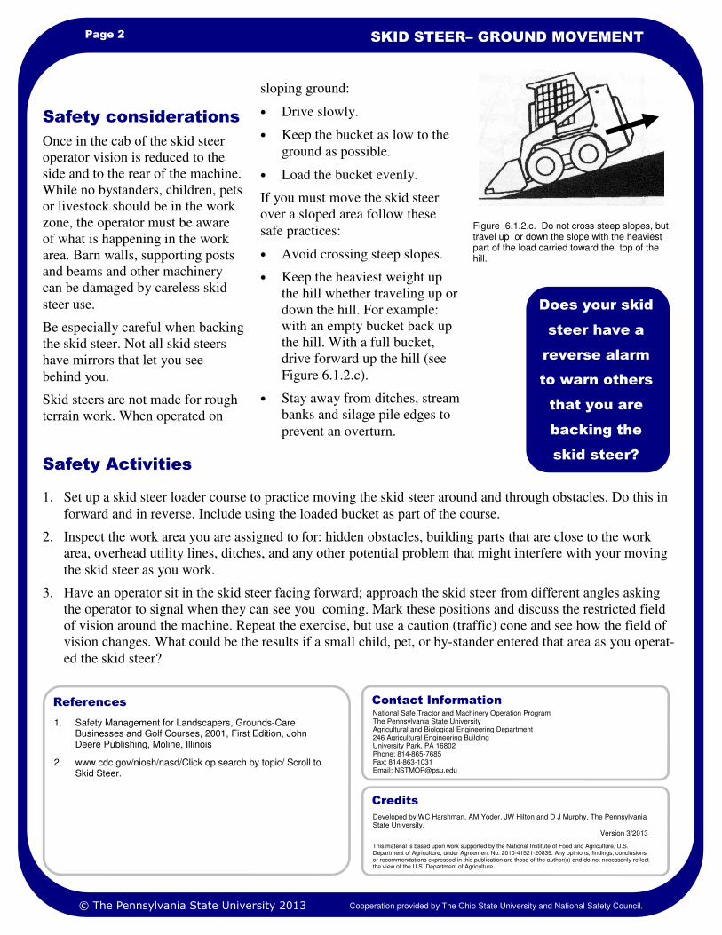
Newer models of skid steers are
equipped with “joystick” controls.
Joysticks can control movement,
steering, and the hydraulic
functions of raising and lowering
the bucket or tilting the bucket
forward and back. Joysticks have
internationally accepted symbols to
indicate their function (Figure
6.1.2.b). In some cases there may
be dual functions for the joy stick
depending upon the mode of use
selected.
Study the operation symbols or ask
your supervisor to explain how the
joystick or any other component
you do not understand is used.
Introduction
Figure 6.1.2.a. Control levers for moving or steering a skid steer are pushed forward, pulled back, or some combination to “skid” the ma-chine in the direction you wish to go. Notice the lap bar which restrains the operator in the skid steer cab.
By letting go of the
skid steer control
levers they will
return to a neutral
position and you will
stop moving.
NATIONAL SAFE TRACTOR AND MACHINERY OPERATION PROGRAM
HOSTA Task Sheet 6.1.2
Related Task Sheets:
Skid Steers 6.1
© The Pennsylvania State University 2013 Cooperation provided by The Ohio State University and National Safety Council.
Figure 6.1.2.b Joystick controls reduce operator fatigue. The joystick can be rotated to many positions and has finger-tip button controls to move the skid steer, raise/lower lift arms, tip the bucket, and operate hydraulic powered accessories.
Page 2 SKID STEER– GROUND MOVEMENT
1. Safety Management for Landscapers, Grounds-Care Businesses and Golf Courses, 2001, First Edition, John Deere Publishing, Moline, Illinois
2. www.cdc.gov/niosh/nasd/Click op search by topic/ Scroll to Skid Steer.
References
1. Set up a skid steer loader course to practice moving the skid steer around and through obstacles. Do this in
forward and in reverse. Include using the loaded bucket as part of the course.
2. Inspect the work area you are assigned to for: hidden obstacles, building parts that are close to the work
area, overhead utility lines, ditches, and any other potential problem that might interfere with your moving
the skid steer as you work.
3. Have an operator sit in the skid steer facing forward; approach the skid steer from different angles asking
the operator to signal when they can see you coming. Mark these positions and discuss the restricted field
of vision around the machine. Repeat the exercise, but use a caution (traffic) cone and see how the field of
vision changes. What could be the results if a small child, pet, or by-stander entered that area as you operat-
ed the skid steer?
Safety Activities
sloping ground:
• Drive slowly.
• Keep the bucket as low to the
ground as possible.
• Load the bucket evenly.
If you must move the skid steer
over a sloped area follow these
safe practices:
• Avoid crossing steep slopes.
• Keep the heaviest weight up
the hill whether traveling up or
down the hill. For example:
with an empty bucket back up
the hill. With a full bucket,
drive forward up the hill (see
Figure 6.1.2.c).
• Stay away from ditches, stream
banks and silage pile edges to
prevent an overturn.
Once in the cab of the skid steer
operator vision is reduced to the
side and to the rear of the machine.
While no bystanders, children, pets
or livestock should be in the work
zone, the operator must be aware
of what is happening in the work
area. Barn walls, supporting posts
and beams and other machinery
can be damaged by careless skid
steer use.
Be especially careful when backing
the skid steer. Not all skid steers
have mirrors that let you see
behind you.
Skid steers are not made for rough
terrain work. When operated on
Safety considerations
Does your skid
steer have a
reverse alarm
to warn others
that you are
backing the
skid steer?
Figure 6.1.2.c. Do not cross steep slopes, but travel up or down the slope with the heaviest part of the load carried toward the top of the hill.
National Safe Tractor and Machinery Operation Program The Pennsylvania State University Agricultural and Biological Engineering Department 246 Agricultural Engineering Building University Park, PA 16802 Phone: 814-865-7685 Fax: 814-863-1031 Email: [email protected]
Contact Information
Developed by WC Harshman, AM Yoder, JW Hilton and D J Murphy, The Pennsylvania State University. Version 3/2013
This material is based upon work supported by the National Institute of Food and Agriculture, U.S. Department of Agriculture, under Agreement No. 2010-41521-20839. Any opinions, findings, conclusions, or recommendations expressed in this publication are those of the author(s) and do not necessarily reflect the view of the U.S. Department of Agriculture.
Credits
© The Pennsylvania State University 2013 Cooperation provided by The Ohio State University and National Safety Council.
SKID STEER– ATTACHING
ACCESSORIES
Learning Goals
• To safely attach skid steer
attachments.
Skid steers can be used for a
variety of tasks. Commonly the
skid steer is equipped with a scoop
bucket to move soil, gravel, feed,
and more. Attachments like pallet
forks, post hole augers, soil
preparation tools, and powered
brooms will mean that you will
change one of these accessories for
another.
This task sheet will discuss the
skid steer quick attachment
procedures and how to do this
important job safely.
Know the parts Boom mounted attachments can be
changed quickly. The parts of the
system include:
A. Pivoting mounting plate
attached to the boom lift arms
B. Latch handles to lock the
attachment to the pivoting
mounting plate
C. Attachment saddle (part of the
attachment)
the top of the mounting plate under
the attachment saddle. Raise the
mounting plate using the foot or
hand lever controls until the back
surface of the attachment rests
against the mounting plate. The
attachment can then be lowered
with the bucket rolled forward
(bucket does not touch the ground).
It is ready to be locked into place.
To be safe, turn off the engine, set
the parking brake, and exit the skid
steer. Push the locking levers down
firmly to engage the lock pins into
the retaining tabs.
Note: Some Skid Steers may be
equipped with a push-button
attachment locking system
electrically activating hydraulic
pins from the operator’s seat.
Reverse the process to remove the
attachment. When attachment is
free, lower the boom slightly and
slowly back away from the
attachment. Be sure the attachment
is setting in a stable position.
Introduction
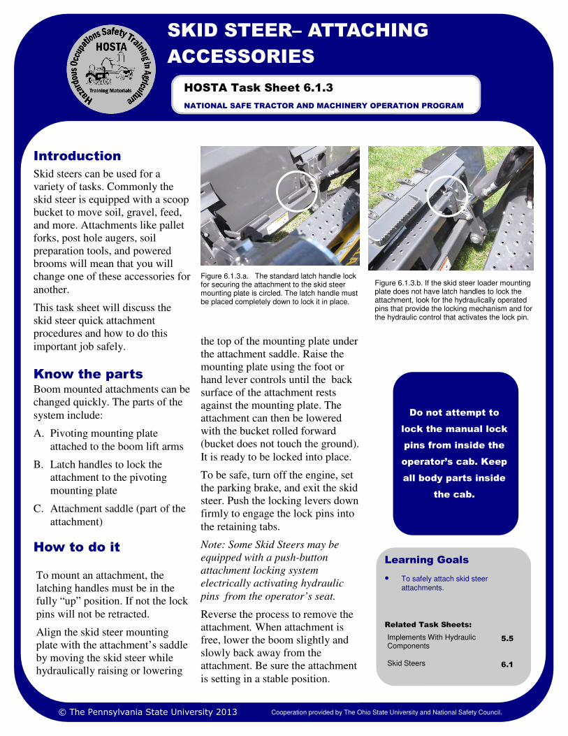
Figure 6.1.3.a. The standard latch handle lock for securing the attachment to the skid steer mounting plate is circled. The latch handle must be placed completely down to lock it in place.
Do not attempt to
lock the manual lock
pins from inside the
operator’s cab. Keep
all body parts inside
the cab.
NATIONAL SAFE TRACTOR AND MACHINERY OPERATION PROGRAM
HOSTA Task Sheet 6.1.3
Related Task Sheets:
Implements With Hydraulic Components
5.5
Skid Steers 6.1
© The Pennsylvania State University 2013 Cooperation provided by The Ohio State University and National Safety Council.
How to do it
To mount an attachment, the
latching handles must be in the
fully “up” position. If not the lock
pins will not be retracted.
Align the skid steer mounting
plate with the attachment’s saddle
by moving the skid steer while
hydraulically raising or lowering
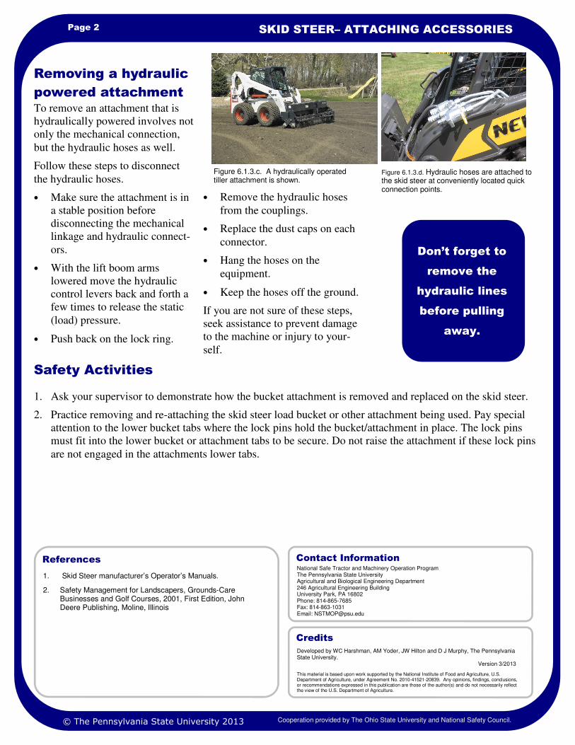
Figure 6.1.3.b. If the skid steer loader mounting plate does not have latch handles to lock the attachment, look for the hydraulically operated pins that provide the locking mechanism and for the hydraulic control that activates the lock pin.
Page 2 SKID STEER– ATTACHING ACCESSORIES
1. Skid Steer manufacturer’s Operator’s Manuals.
2. Safety Management for Landscapers, Grounds-Care Businesses and Golf Courses, 2001, First Edition, John Deere Publishing, Moline, Illinois
References
1. Ask your supervisor to demonstrate how the bucket attachment is removed and replaced on the skid steer.
2. Practice removing and re-attaching the skid steer load bucket or other attachment being used. Pay special
attention to the lower bucket tabs where the lock pins hold the bucket/attachment in place. The lock pins
must fit into the lower bucket or attachment tabs to be secure. Do not raise the attachment if these lock pins
are not engaged in the attachments lower tabs.
Safety Activities
• Remove the hydraulic hoses
from the couplings.
• Replace the dust caps on each
connector.
• Hang the hoses on the
equipment.
• Keep the hoses off the ground.
If you are not sure of these steps,
seek assistance to prevent damage
to the machine or injury to your-
self.
To remove an attachment that is
hydraulically powered involves not
only the mechanical connection,
but the hydraulic hoses as well.
Follow these steps to disconnect
the hydraulic hoses.
• Make sure the attachment is in
a stable position before
disconnecting the mechanical
linkage and hydraulic connect-
ors.
• With the lift boom arms
lowered move the hydraulic
control levers back and forth a
few times to release the static
(load) pressure.
• Push back on the lock ring.
Removing a hydraulic
powered attachment
Don’t forget to
remove the
hydraulic lines
before pulling
away.
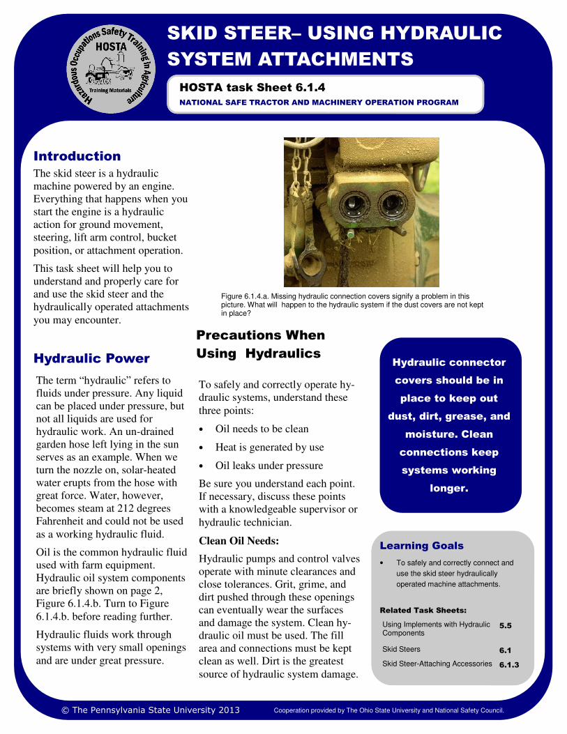
Figure 6.1.3.c. A hydraulically operated tiller attachment is shown.
National Safe Tractor and Machinery Operation Program The Pennsylvania State University Agricultural and Biological Engineering Department 246 Agricultural Engineering Building University Park, PA 16802 Phone: 814-865-7685 Fax: 814-863-1031 Email: [email protected]
Contact Information
Developed by WC Harshman, AM Yoder, JW Hilton and D J Murphy, The Pennsylvania State University. Version 3/2013
This material is based upon work supported by the National Institute of Food and Agriculture, U.S. Department of Agriculture, under Agreement No. 2010-41521-20839. Any opinions, findings, conclusions, or recommendations expressed in this publication are those of the author(s) and do not necessarily reflect the view of the U.S. Department of Agriculture.
Credits
© The Pennsylvania State University 2013
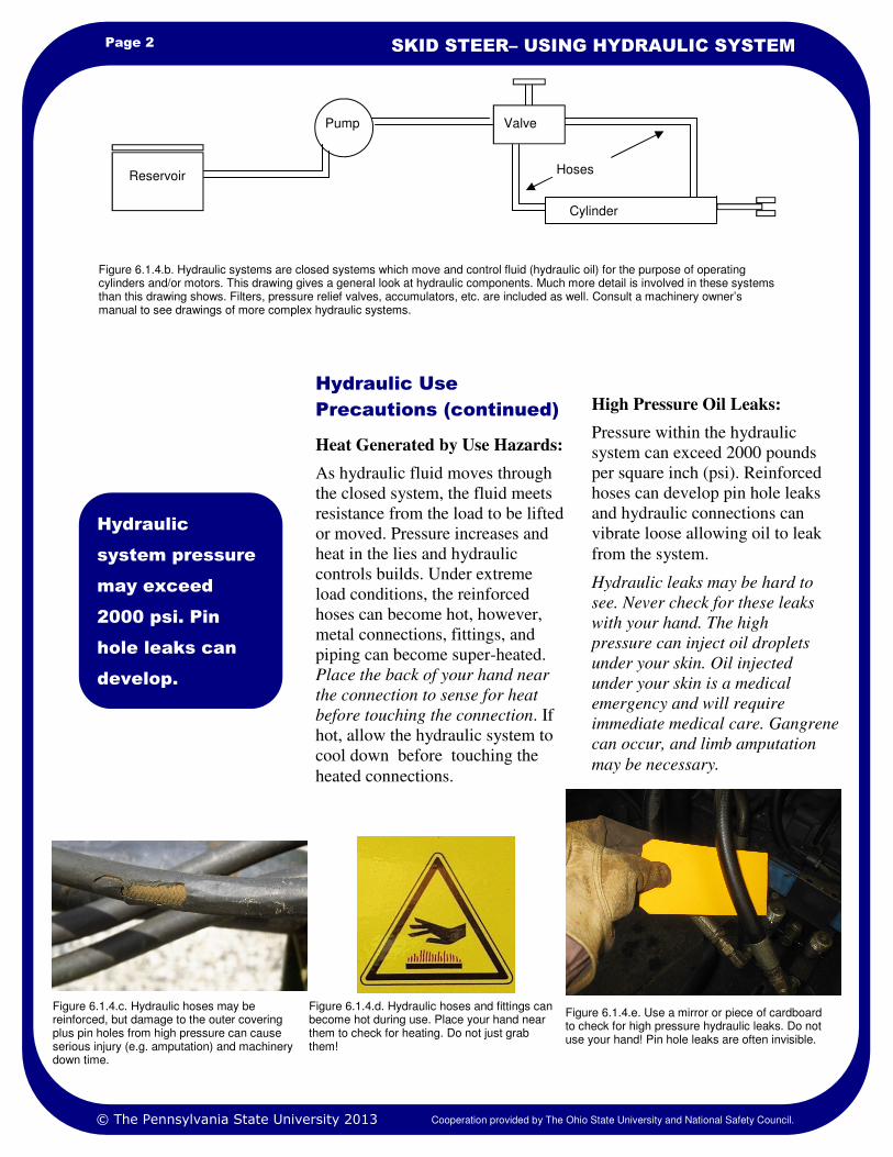
Figure 6.1.3.d. Hydraulic hoses are attached to the skid steer at conveniently located quick connection points.
Cooperation provided by The Ohio State University and National Safety Council.
Learning Goals
• To safely and correctly connect and
use the skid steer hydraulically
operated machine attachments.
Related Task Sheets:
Using Implements with Hydraulic Components
5.5
Skid Steers 6.1
Skid Steer-Attaching Accessories 6.1.3
The skid steer is a hydraulic
machine powered by an engine.
Everything that happens when you
start the engine is a hydraulic
action for ground movement,
steering, lift arm control, bucket
position, or attachment operation.
This task sheet will help you to
understand and properly care for
and use the skid steer and the
hydraulically operated attachments
you may encounter.
Figure 6.1.4.a. Missing hydraulic connection covers signify a problem in this picture. What will happen to the hydraulic system if the dust covers are not kept in place?
Introduction
Precautions When
Using Hydraulics Hydraulic connector
covers should be in
place to keep out
dust, dirt, grease, and
moisture. Clean
connections keep
systems working
longer.
SKID STEER– USING HYDRAULIC
SYSTEM ATTACHMENTS
NATIONAL SAFE TRACTOR AND MACHINERY OPERATION PROGRAM
HOSTA task Sheet 6.1.4
The term “hydraulic” refers to
fluids under pressure. Any liquid
can be placed under pressure, but
not all liquids are used for
hydraulic work. An un-drained
garden hose left lying in the sun
serves as an example. When we
turn the nozzle on, solar-heated
water erupts from the hose with
great force. Water, however,
becomes steam at 212 degrees
Fahrenheit and could not be used
as a working hydraulic fluid.
Oil is the common hydraulic fluid
used with farm equipment.
Hydraulic oil system components
are briefly shown on page 2,
Figure 6.1.4.b. Turn to Figure
6.1.4.b. before reading further.
Hydraulic fluids work through
systems with very small openings
and are under great pressure.
Hydraulic Power
© The Pennsylvania State University 2013 Cooperation provided by The Ohio State University and National Safety Council.
To safely and correctly operate hy-
draulic systems, understand these
three points:
• Oil needs to be clean
• Heat is generated by use
• Oil leaks under pressure
Be sure you understand each point.
If necessary, discuss these points
with a knowledgeable supervisor or
hydraulic technician.
Clean Oil Needs:
Hydraulic pumps and control valves
operate with minute clearances and
close tolerances. Grit, grime, and
dirt pushed through these openings
can eventually wear the surfaces
and damage the system. Clean hy-
draulic oil must be used. The fill
area and connections must be kept
clean as well. Dirt is the greatest
source of hydraulic system damage.
Page 2 SKID STEER– USING HYDRAULIC SYSTEM
High Pressure Oil Leaks:
Pressure within the hydraulic
system can exceed 2000 pounds
per square inch (psi). Reinforced
hoses can develop pin hole leaks
and hydraulic connections can
vibrate loose allowing oil to leak
from the system.
Hydraulic leaks may be hard to
see. Never check for these leaks
with your hand. The high
pressure can inject oil droplets
under your skin. Oil injected
under your skin is a medical
emergency and will require
immediate medical care. Gangrene
can occur, and limb amputation
may be necessary.
Heat Generated by Use Hazards:
As hydraulic fluid moves through
the closed system, the fluid meets
resistance from the load to be lifted
or moved. Pressure increases and
heat in the lies and hydraulic
controls builds. Under extreme
load conditions, the reinforced
hoses can become hot, however,
metal connections, fittings, and
piping can become super-heated.
Place the back of your hand near
the connection to sense for heat
before touching the connection. If
hot, allow the hydraulic system to
cool down before touching the
heated connections.
Hydraulic Use
Precautions (continued)
Hydraulic
system pressure
may exceed
2000 psi. Pin
hole leaks can
develop.
.
Figure 6.1.4.b. Hydraulic systems are closed systems which move and control fluid (hydraulic oil) for the purpose of operating cylinders and/or motors. This drawing gives a general look at hydraulic components. Much more detail is involved in these systems than this drawing shows. Filters, pressure relief valves, accumulators, etc. are included as well. Consult a machinery owner’s manual to see drawings of more complex hydraulic systems.
© The Pennsylvania State University 2013
Figure 6.1.4.d. Hydraulic hoses and fittings can become hot during use. Place your hand near them to check for heating. Do not just grab them!
Figure 6.1.4.e. Use a mirror or piece of cardboard to check for high pressure hydraulic leaks. Do not use your hand! Pin hole leaks are often invisible.
Figure 6.1.4.c. Hydraulic hoses may be reinforced, but damage to the outer covering plus pin holes from high pressure can cause serious injury (e.g. amputation) and machinery down time.
Reservoir
Pump Valve
Cylinder
Hoses
Cooperation provided by The Ohio State University and National Safety Council.
Page 3 HOSTA TASK SHEET 6.1.4
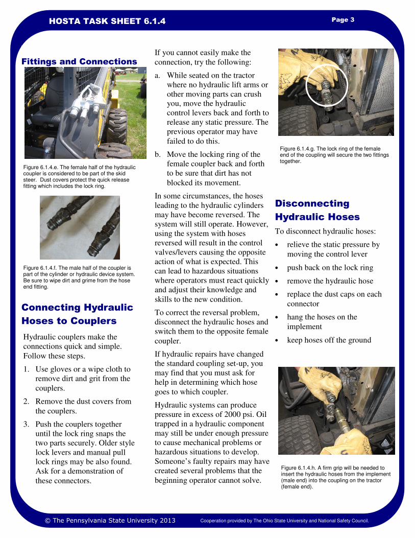
Fittings and Connections
Connecting Hydraulic
Hoses to Couplers
Figure 6.1.4.h. A firm grip will be needed to insert the hydraulic hoses from the implement (male end) into the coupling on the tractor (female end).
To disconnect hydraulic hoses:
• relieve the static pressure by
moving the control lever
• push back on the lock ring
• remove the hydraulic hose
• replace the dust caps on each
connector
• hang the hoses on the
implement
• keep hoses off the ground
Figure 6.1.4.e. The female half of the hydraulic coupler is considered to be part of the skid steer. Dust covers protect the quick release fitting which includes the lock ring.
Figure 6.1.4.f. The male half of the coupler is part of the cylinder or hydraulic device system. Be sure to wipe dirt and grime from the hose end fitting.
Hydraulic couplers make the
connections quick and simple.
Follow these steps.
1. Use gloves or a wipe cloth to
remove dirt and grit from the
couplers.
2. Remove the dust covers from
the couplers.
3. Push the couplers together
until the lock ring snaps the
two parts securely. Older style
lock levers and manual pull
lock rings may be also found.
Ask for a demonstration of
these connectors.
If you cannot easily make the
connection, try the following:
a. While seated on the tractor
where no hydraulic lift arms or
other moving parts can crush
you, move the hydraulic
control levers back and forth to
release any static pressure. The
previous operator may have
failed to do this.
b. Move the locking ring of the
female coupler back and forth
to be sure that dirt has not
blocked its movement.
In some circumstances, the hoses
leading to the hydraulic cylinders
may have become reversed. The
system will still operate. However,
using the system with hoses
reversed will result in the control
valves/levers causing the opposite
action of what is expected. This
can lead to hazardous situations
where operators must react quickly
and adjust their knowledge and
skills to the new condition.
To correct the reversal problem,
disconnect the hydraulic hoses and
switch them to the opposite female
coupler.
If hydraulic repairs have changed
the standard coupling set-up, you
may find that you must ask for
help in determining which hose
goes to which coupler.
Hydraulic systems can produce
pressure in excess of 2000 psi. Oil
trapped in a hydraulic component
may still be under enough pressure
to cause mechanical problems or
hazardous situations to develop.
Someone’s faulty repairs may have
created several problems that the
beginning operator cannot solve.
© The Pennsylvania State University 2013 Cooperation provided by The Ohio State University and National Safety Council.
Disconnecting
Hydraulic Hoses
Figure 6.1.4.g. The lock ring of the female end of the coupling will secure the two fittings together.
1. www.asae.org/Click on Technical Library/Scroll to Standards/Type hydraulic couplers/Open PDF file S366, December 2001.
2. Safety Management for Landscapers, Grounds-Care Businesses and Golf Courses, 2001, 1st Edition, John Deere Publishing, Moline, Illinois.
3. Operator’s Manuals for various skid steer models.
References
Page 4 SKID STEER– USING HYDRAULIC SYSTEM
1. Identify all the hydraulic system components that are external to the skid steer. You may wish to name the
parts and their purpose to a friend or mentor or supervisor.
2. Check the hydraulic fluid level of a skid steer. Could you find where to check the fluid level? If not use the
Operator’s Manual to find the location of the hydraulic fluid fill and/or check point.
3. Practice connecting the hydraulic hoses to the skid steer coupler until you can do this easily..
4. Use the skid steer hydraulic system for practice:
a. raising and lowering the lift arms
b. tipping the bucket forward and rolling it back
5. Answer these questions:
A. What is the greatest source of damage to a hydraulic system?
1. Water 2. Dirt 3. Air 4. None of these
B. The term hydraulic refers to:
1. Fluid under pressure 2. Air under pressure 3. Gas under pressure
C. Hydraulic pressures on skid steers and attachments may exceed ______________psi
1. 2000 psi 2. 4000 psi 3. 10,000 psi
D. The safe way to check for pin hole leaks in the hydraulic system is to:
1. Rub your hand over the hose.
2. Hold a match near where you suspect the leak.
3. Hold a piece of metal or cardboard near where you suspect the leak.
Safety Activities
National Safe Tractor and Machinery Operation Program The Pennsylvania State University Agricultural and Biological Engineering Department 246 Agricultural Engineering Building University Park, PA 16802 Phone: 814-865-7685 Fax: 814-863-1031 Email: [email protected]
Contact Information
Developed by WC Harshman, AM Yoder, JW Hilton and D J Murphy, The Pennsylvania State University. Version 3/2013
This material is based upon work supported by the National Institute of Food and Agriculture, U.S. Department of Agriculture, under Agreement No. 2010-41521-20839. Any opinions, findings, conclusions, or recommendations expressed in this publication are those of the author(s) and do not necessarily reflect the view of the U.S. Department of Agriculture.
Credits
© The Pennsylvania State University 2013 Cooperation provided by The Ohio State University and National Safety Council.
Learning Goals
• To safely use ATVs and utility
vehicles for work and recreational
purposes
Related Task Sheets:
Injuries Involving Youth 2.1
Age-Appropriate Tasks 2.4
Mechanical Hazards 3.1
Tractor Stability 4.12
Using the Tractor Safely 4.13
Skid Steers 7.1
Tractor Hazards 4.2
They look like fun. They can go
fast. They can travel in the woods.
They can kill and injure. What are
they? They are ATVs and utility
vehicles.
In a recent year, 90,000 injuries
and 120 deaths were reported due
to use of these fun vehicles. The
U.S. Consumer Product Safety
Commission reports that 4 of every
10 people treated in hospital
emergency rooms are younger than
age 16. Why would this be the
case?
This task sheet discusses safe use
of ATVs and utility vehicles as
they are used for work and
recreational purposes.
All-Terrain Vehicles
As the name implies, all-terrain
vehicles (ATVs) can travel almost
anywhere. Rough terrain, steep
slopes, rutted mountain roads, and
muddy conditions make ATV use
appealing. Sportsmen, leisure time
enthusiasts, and workers use
ATVs. ATVs have become a
valuable tool for farm and ranch
tasks.
ATVs are designed for work. Other
task sheets discuss tractor and skid
steer stability. Review Task Sheets
4.12, 4.13, and 7.1. Then consider
these ATV design features.
• stability
• suspension
Introduction
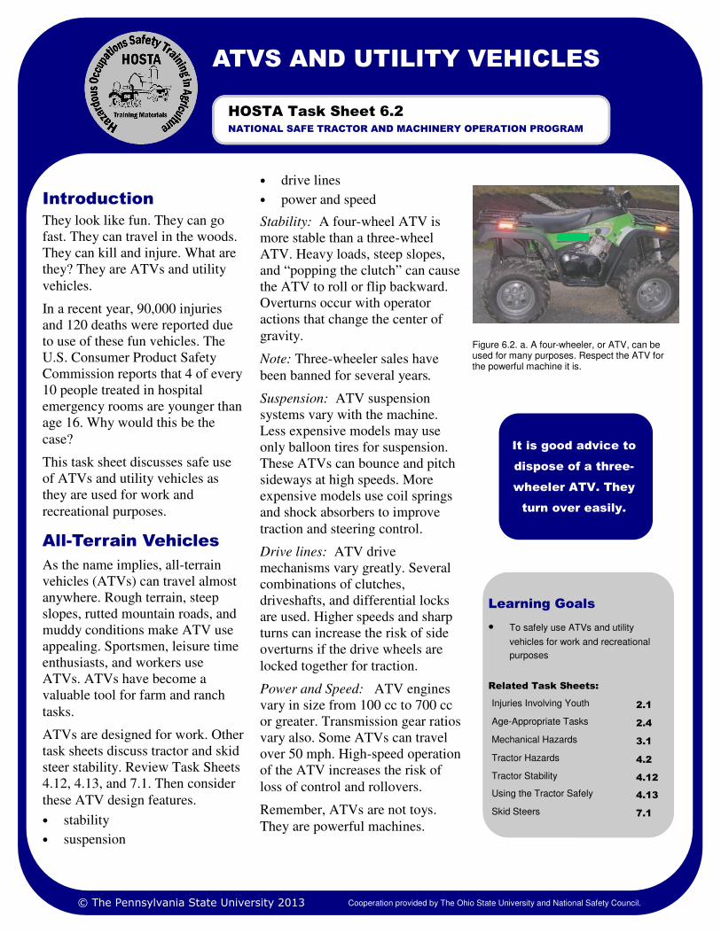
Figure 6.2. a. A four-wheeler, or ATV, can be used for many purposes. Respect the ATV for the powerful machine it is.
It is good advice to
dispose of a three-
wheeler ATV. They
turn over easily.
ATVS AND UTILITY VEHICLES
NATIONAL SAFE TRACTOR AND MACHINERY OPERATION PROGRAM
HOSTA Task Sheet 6.2
• drive lines
• power and speed
Stability: A four-wheel ATV is
more stable than a three-wheel
ATV. Heavy loads, steep slopes,
and “popping the clutch” can cause
the ATV to roll or flip backward.
Overturns occur with operator
actions that change the center of
gravity.
Note: Three-wheeler sales have
been banned for several years.
Suspension: ATV suspension
systems vary with the machine.
Less expensive models may use
only balloon tires for suspension.
These ATVs can bounce and pitch
sideways at high speeds. More
expensive models use coil springs
and shock absorbers to improve
traction and steering control.
Drive lines: ATV drive
mechanisms vary greatly. Several
combinations of clutches,
driveshafts, and differential locks
are used. Higher speeds and sharp
turns can increase the risk of side
overturns if the drive wheels are
locked together for traction.
Power and Speed: ATV engines
vary in size from 100 cc to 700 cc
or greater. Transmission gear ratios
vary also. Some ATVs can travel
over 50 mph. High-speed operation
of the ATV increases the risk of
loss of control and rollovers.
Remember, ATVs are not toys.
They are powerful machines.
© The Pennsylvania State University 2013 Cooperation provided by The Ohio State University and National Safety Council.
Page 2 ATVS AND UTILITY VEHICLES
individuals 16 and older. The
child’s strength, skills, and
maturity determine readiness to
operate an ATV.
• Carrying passengers increases
the risk of overturn injury and
death. A second person
changes the center of gravity of
the machine and the machine’s
steering ability.
• Know the machine’s
limitations. Operating on steep
terrain, pulling heavy loads,
excessive speed, and “wheelie”
type starts can result in ATV
turnover.
• Wear a full-face shield helmet.
The helmet should fit snugly
and securely. It should be
labeled with the American
National Standards Institute
(ANSI) Z90.1 label.
• If a face shield is not part of
the helmet, wear goggles or a
separate face shield, especially
at high speeds or in wooded
Safety training for ATV use is the
first step in being a qualified ATV
operator. Local ATV dealers, ATV
clubs, and safety professionals
from Cooperative Extension, state
Departmenrts of Conservation and
Natural Resources and farm
organizations may offer safe ATV
operation programs. The Specialty
Vehicle Institute of America
(SVIA) provides training as well.
Visit them on the Internet at
www.svia.org. At a minimum, use
the operator’s manual and the
safety signs on the ATV to help
educate yourself before using the
machine.
Here are some guidelines for safe
ATV use:
• Manufacturers recommend that
ATVs with engine sizes greater
than 70cc be sold only for
children 12 and older and that
ATVs with engines greater
than 90cc be sold only for
ATV Operation
and Safety
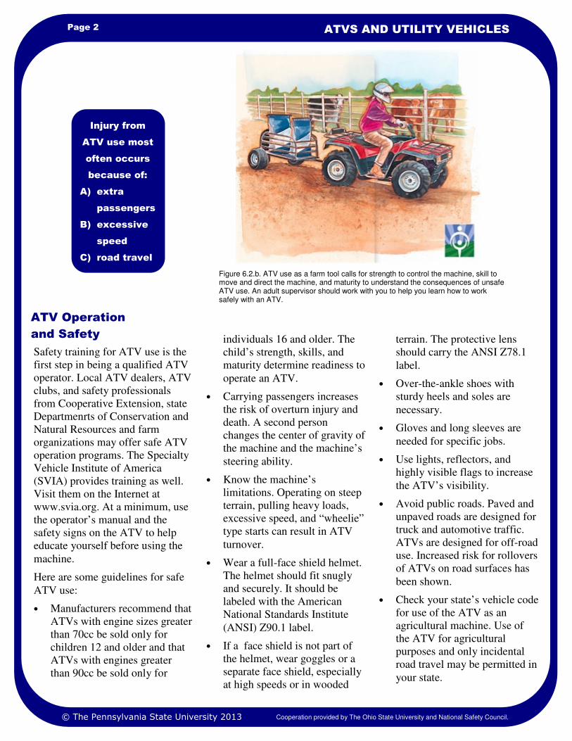
Injury from
ATV use most
often occurs
because of:
A) extra
passengers
B) excessive
speed
C) road travel
Figure 6.2.b. ATV use as a farm tool calls for strength to control the machine, skill to move and direct the machine, and maturity to understand the consequences of unsafe ATV use. An adult supervisor should work with you to help you learn how to work safely with an ATV.
terrain. The protective lens
should carry the ANSI Z78.1
label.
• Over-the-ankle shoes with
sturdy heels and soles are
necessary.
• Gloves and long sleeves are
needed for specific jobs.
• Use lights, reflectors, and
highly visible flags to increase
the ATV’s visibility.
• Avoid public roads. Paved and
unpaved roads are designed for
truck and automotive traffic.
ATVs are designed for off-road
use. Increased risk for rollovers
of ATVs on road surfaces has
been shown.
• Check your state’s vehicle code
for use of the ATV as an
agricultural machine. Use of
the ATV for agricultural
purposes and only incidental
road travel may be permitted in
your state.
© The Pennsylvania State University 2013 Cooperation provided by The Ohio State University and National Safety Council.
Page 3 HOSTA TASK SHEET 6.2
Utility vehicles are similar to golf
carts except they are fitted with
cargo boxes to carry work material.
The utility vehicle can have four,
five, or six wheels depending upon
its use. The UV weighs about
1,000 pounds and can carry
several hundred pounds of cargo.
The machine can be diesel,
gasoline, electric, or hydrogen fuel
cell powered.
Like other farm machines, the
utility vehicle is made for work
purposes. Hauling feed, mulch
materials, and supplies makes it a
convenient transport for small jobs.
Like an ATV, the utility vehicle is
a tool and not a toy.
Safe operation of the utility vehicle
requires the same safe work habits
as used with tractors, skid steer
loaders, and ATVs.
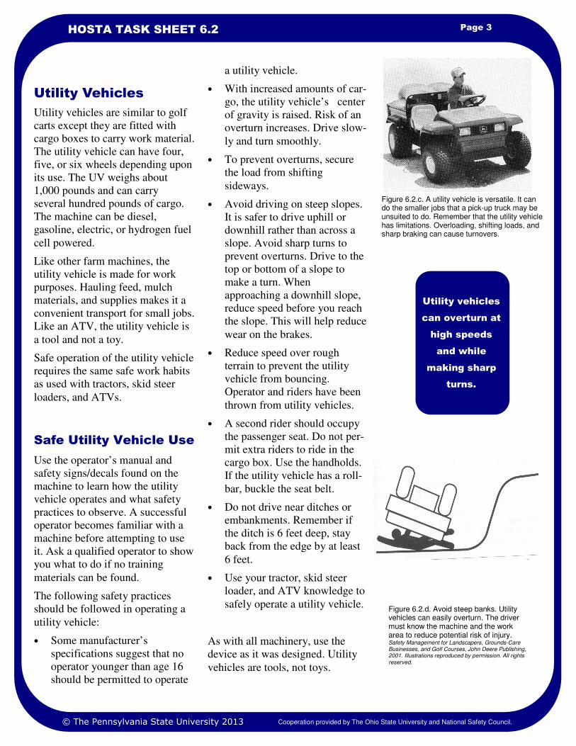
a utility vehicle.
• With increased amounts of car-
go, the utility vehicle’s center
of gravity is raised. Risk of an
overturn increases. Drive slow-
ly and turn smoothly.
• To prevent overturns, secure
the load from shifting
sideways.
• Avoid driving on steep slopes.
It is safer to drive uphill or
downhill rather than across a
slope. Avoid sharp turns to
prevent overturns. Drive to the
top or bottom of a slope to
make a turn. When
approaching a downhill slope,
reduce speed before you reach
the slope. This will help reduce
wear on the brakes.
• Reduce speed over rough
terrain to prevent the utility
vehicle from bouncing.
Operator and riders have been
thrown from utility vehicles.
• A second rider should occupy
the passenger seat. Do not per-
mit extra riders to ride in the
cargo box. Use the handholds.
If the utility vehicle has a roll-
bar, buckle the seat belt.
• Do not drive near ditches or
embankments. Remember if
the ditch is 6 feet deep, stay
back from the edge by at least
6 feet.
• Use your tractor, skid steer
loader, and ATV knowledge to
safely operate a utility vehicle.
As with all machinery, use the
device as it was designed. Utility
vehicles are tools, not toys.
Use the operator’s manual and
safety signs/decals found on the
machine to learn how the utility
vehicle operates and what safety
practices to observe. A successful
operator becomes familiar with a
machine before attempting to use
it. Ask a qualified operator to show
you what to do if no training
materials can be found.
The following safety practices
should be followed in operating a
utility vehicle:
• Some manufacturer’s
specifications suggest that no
operator younger than age 16
should be permitted to operate
Utility Vehicles
Safe Utility Vehicle Use
Utility vehicles
can overturn at
high speeds
and while
making sharp
turns.
Figure 6.2.c. A utility vehicle is versatile. It can do the smaller jobs that a pick-up truck may be unsuited to do. Remember that the utility vehicle has limitations. Overloading, shifting loads, and sharp braking can cause turnovers.
Figure 6.2.d. Avoid steep banks. Utility vehicles can easily overturn. The driver must know the machine and the work area to reduce potential risk of injury. Safety Management for Landscapers, Grounds-Care Businesses, and Golf Courses, John Deere Publishing, 2001. Illustrations reproduced by permission. All rights reserved.
© The Pennsylvania State University 2013 Cooperation provided by The Ohio State University and National Safety Council.
1. Safety Management for Landscapers, Grounds-Care Businesses, and Golf Courses, John Deere Publishing, 2001. Illustrations reproduced by permission. All rights reserved.
2. www.cdc.gov/nasd/ Search the National Ag Safety Database site by topic for ATV information.
3. www.atvsafety.org/Search site for interactive quizzes, word searches, and puzzles.
4. www.svia.org/Search the Specialty Vehicle Institute of America site for ATV information.
References
Page 4 ATVS AND UTILITY VEHICLES
1. Use the Internet website www.atvsafety.org to solve crossword puzzles or to play word search games
related to all-terrain vehicle (ATV) safety.
2. Visit the John Deere website, www.JohnDeere.com, or the Bobcat website, www.bobcat.com, to learn about
all-terrain vehicle (ATV) specifications for weight, payload, and engine size.
3. Collect newspaper, magazine, or Internet news articles about ATV and utility vehicle injuries and deaths.
Create a poster presentation to display at a local ATV or utility vehicle dealership.
4. What does the designation “100cc engine” represent? Using the math formula for volume of a cylinder (ask
your teacher), calculate the diameter and height of the cylinder that would represent a 100cc engine
cylinder. Use a sheet of paper to construct the cylinder. Answer the same question for a 500cc engine
cylinder.
Safety Activities
National Safe Tractor and Machinery Operation Program The Pennsylvania State University Agricultural and Biological Engineering Department 246 Agricultural Engineering Building University Park, PA 16802 Phone: 814-865-7685 Fax: 814-863-1031 Email: [email protected]
Contact Information
Developed by WC Harshman, AM Yoder, JW Hilton and D J Murphy, The Pennsylvania State University. Reviewed by TL Bean and D Jepsen, The Ohio State University and S Steel, National Safety Council. Revised 3/2013
This material is based upon work supported by the National Institute of Food and Agriculture, U.S. Department of Agriculture, under Agreement Nos. 2001-41521-01263 and 2010-41521-20839. Any opinions, findings, conclusions, or recommendations expressed in this publication are those of the author(s) and do not necessarily reflect the view of the U.S. Department of Agriculture.
Credits
© The Pennsylvania State University 2013 Cooperation provided by The Ohio State University and National Safety Council.
Learning Goals
• To understand how a telehandler
operation
• To understand the concepts of
machine and load stability in operating
a telehandler
Related Task Sheets:
Hand Signals 2.9
Mechanical Hazards 3.1
Tractor Hazards 4.1
Tractor Stability 4.12
Skid Steers 6.1
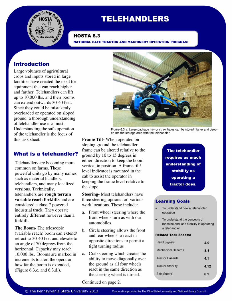
Large volumes of agricultural
crops and inputs stored in large
facilities have created the need for
equipment that can reach higher
and farther. Telehandlers can lift
up to 10,000 lbs. and their booms
can extend outwards 30-40 feet.
Since they could be mistakenly
overloaded or operated on sloped
ground a thorough understanding
of telehandler use is a must.
Understanding the safe operation
of the telehandler is the focus of
this task sheet.
What is a telehandler?
Introduction
Figure 6.3.a. Large package hay or straw bales can be stored higher and deep-er into the storage area with the telehandler.
The telehandler
requires as much
understanding of
stability as
operating a
tractor does.
TELEHANDLERS
NATIONAL SAFE TRACTOR AND MACHINERY OPERATION PROGRAM
HOSTA 6.3
Telehandlers are becoming more
common on farms. These
powerful units go by many names
such as material handlers,
telehandlers, and many localized
versions. Technically,
telehandlers are rough terrain
variable reach forklifts and are
considered a class 7 powered
industrial truck. They operate
entirely different however than a
forklift.
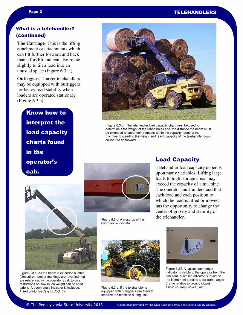
The Boom- The telescopic
(variable reach) boom can extend/
retract to 30-40 feet and elevate to
an angle of 70 degrees from the
horizontal. Capacity may reach
10,000 lbs. Booms are marked in
increments to alert the operator
how far the boom is extended,
(Figure 6.3.c. and 6.3.d.).
© The Pennsylvania State University 2013 Cooperation provided by The Ohio State University and National Safety Council.
Frame Tilt- When operated on
sloping ground the telehandler
frame can be altered relative to the
ground by 10 to 15 degrees in
either direction to keep the boom
vertical in position. A frame tilt/
level indicator is mounted in the
cab to assist the operator in
keeping the frame level relative to
the slope.
Steering- Most telehandlers have
three steering options for various
work locations. These include:
a. Front wheel steering where the
front wheels turn as with our
automobiles
b. Circle steering allows the front
and rear wheels to react in
opposite directions to permit a
tight turning radius
c. Crab steering which creates the
ability to move diagonally over
the ground as all four wheels
react in the same direction as
the steering wheel is turned.
Continued on page 2.
Page 2 TELEHANDLERS
Telehandler load capacity depends
upon many variables. Lifting large
loads to high storage areas may
exceed the capacity of a machine.
The operator must understand that
each load and each position to
which the load is lifted or moved
has the opportunity to change the
center of gravity and stability of
the telehandler.
Load Capacity
.Figure 6.3.b. The telehandler load capacity chart must be used to determine if the weight of the round bales and the distance the boom must be extended to store them remains within the capacity range of the machine. Exceeding the weight and reach capacity of the telehandler could cause it to tip forward.
© The Pennsylvania State University 2013 Cooperation provided by The Ohio State University and National Safety Council.
Figure 6.3.c. As the boom is extended a letter (circled) or number markings are revealed that are referenced in the operator’s cab to give restrictions on how much weight can be lifted safely. A boom angle indicator is included. Insert photo courtesy of JLG, Inc.
Know how to
interpret the
load capacity
charts found
in the
operator’s
cab.
Figure 6.3.f. A typical boom angle indicator is visible to the operator from the cab seat. A similar indicator is found on the instrument panel to show frame angle (frame relative to ground slope). Photo courtesy of JLG, Inc.
What is a telehandler?
(continued)
The Carriage- This is the lifting
attachment or attachments which
can tilt further forward and back
than a forklift and can also rotate
slightly to tilt a load into an
unusual space (Figure 6.3.a.).
Outriggers– Larger telehandlers
may be equipped with outriggers
for heavy load stability when
loaders are operated stationary
(Figure 6.3.e).
Figure 6.3.d. A close-up of the boom angle indicator.
Figure 6.3.e. If the telehandler is equipped with outriggers use them to stabilize the machine during use.
Page 3 HOSTA 6.3
Moving/Using the
Telehandler
Start-up procedure
If the telehandler
has outriggers,
be sure they are
lowered during
lifting (for
stability) and
then raised for
travel.
Following your training period on
the telehandler, use this reminder
on how to start the machine.
1. Complete a pre-inspection of
the machine.
2. Fasten your safety belt.
3. Observe that all controls are in
the neutral position.
4. Turn ignition switch to
pre-heat position if so
equipped; start the engine
when signaled.
5. Warm up the engine at 1/2
throttle.
6. Close the cab door.
7. Check lights, back-up alarm,
and horn.
Before moving the telehandler:
• Check the steering and braking
controls.
• Be sure the boom extension
and leveling controls are
operational, but test these on
level ground.
• Lower the outriggers before
lifting.
• Practice using the lift and
leveling controls before
moving a load.
• Check that other personnel
and machines are not in the
area.
• Plan your travel for best
visibility.
• Keep the boom retracted and as
close to the ground as possible.
© The Pennsylvania State University 2013 Cooperation provided by The Ohio State University and National Safety Council.
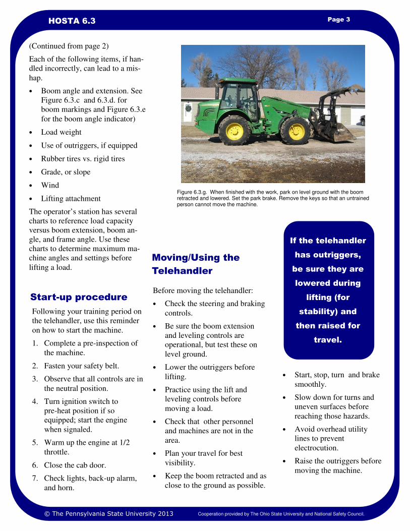
Figure 6.3.g. When finished with the work, park on level ground with the boom retracted and lowered. Set the park brake. Remove the keys so that an untrained person cannot move the machine.
(Continued from page 2)
Each of the following items, if han-
dled incorrectly, can lead to a mis-
hap.
• Boom angle and extension. See
Figure 6.3.c and 6.3.d. for
boom markings and Figure 6.3.e
for the boom angle indicator)
• Load weight
• Use of outriggers, if equipped
• Rubber tires vs. rigid tires
• Grade, or slope
• Wind
• Lifting attachment
The operator’s station has several
charts to reference load capacity
versus boom extension, boom an-
gle, and frame angle. Use these
charts to determine maximum ma-
chine angles and settings before
lifting a load.
• Start, stop, turn and brake
smoothly.
• Slow down for turns and
uneven surfaces before
reaching those hazards.
• Avoid overhead utility
lines to prevent
electrocution.
• Raise the outriggers before
moving the machine.
1. Websites for various telehandler manufacturers Operator’s Manual
2. Website, www.agsafety.psu.edu. Scroll to Publications, E47 Skid-Steer Safety for Farm and Landscape
References
Page 4 TELEHANDLERS
1. If you have never operated a telehandler, visit an equipment dealership and ask to sit in telehandler’s cab to
observe what controls are available and where they are located. This may be done with your employer’s
guidance as well.
2. Use the operator’s manual for the telehandler you will operate to study the controls and instrument gauges
as you sit in the operator’s position.
3. Practice starting and stopping the telehandler, raising and extending/retracting the boom, leveling the frame
of the telehandler while sitting with the parking brake set, and/or lowering and raising the outriggers.
4. Practice driving the telehandler with no load. Use the 2-wheel, 4-wheel, and crab drive functions.
5. Practice picking up and lifting a load, extending the loaded boom, and lowering the load.
Safety Activities
National Safe Tractor and Machinery Operation Program The Pennsylvania State University Agricultural and Biological Engineering Department 246 Agricultural Engineering Building University Park, PA 16802 Phone: 814-865-7685 Fax: 814-863-1031 Email: [email protected]
Contact Information
Developed by WC Harshman, AM Yoder, JW Hilton and D J Murphy, The Pennsylvania State University. Version 3/2013
This material is based upon work supported by the National Institute of Food and Agriculture, U.S. Department of Agriculture, under Agreement No. 2010-41521-20839. Any opinions, findings, conclusions, or recommendations expressed in this publication are those of the author(s) and do not necessarily reflect the view of the U.S. Department of Agriculture.
Credits
© The Pennsylvania State University 2013 Cooperation provided by The Ohio State University and National Safety Council.
Shut-down procedure
When the work is completed park in a safe location on level ground away from other equipment
and traffic.
Follow these steps:
1. Apply the park brake.
2. Shift transmission to neutral
3. Retract boom and lower boom and attachments (see Figure 4).
4. Let engine idle for 3-5 minutes to cool.
5. Shut off engine and remove key as directed by the employer/supervisor.
6. Remove seat belt.
7. Use grab handles and exit the machine safely.
8. Block wheels if parking on a slope is unavoidable.
9. Some models may have a master electrical switch to disconnect the battery from service.
Disconnect if so.
Learning Goals
• To safely use a tractor-mounted, front-
end loader.
• To understand how the center of
gravity of a farm tractor changes as the
front-end loader is used.
Related Task Sheets:
Tractor Hazards 4.2
Tractor Stability 4.12
Using the Tractor Safely 4.13
A front-end loader (high-lift with
bucket or other accessories)
mounted on a tractor is a valuable
tool for lifting, moving, dragging,
and pushing items such as soil,
gravel, large round bales,
equipment parts, and road repair
materials. Using the front-end
loader requires an understanding of
machine capacity limitations,
center of gravity, and an awareness
of work surroundings.
This task sheet discusses safely
using a front-end loader mounted
on a farm tractor.(Similar task
sheets dealing with skid steer and
material handlers also discuss these
safety ideas.) the tractor’s mid-frame and may
serve as the support legs. Some
loaders will have support legs
which support the front end loader
frame when it has been removed
from the tractor if different than
the tower columns.
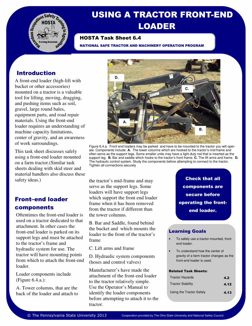
B. Bar and Saddle, found behind
the bucket and which mounts the
loader to the front of the tractor’s
frame
C. Lift arms and frame
D. Hydraulic system components
(hoses and control valves)
Manufacturer’s have made the
attachment of the front-end loader
to the tractor relatively simple.
Use the Operator’s Manual to
identify the loader components
before attempting to attach it to the
tractor.
Introduction
Figure 6.4.a. Front end loaders may be parked and have to be mounted to the tractor you will oper-ate. Components include: A. The tower columns which are hooked to the tractor’s mid-frame and often serve as the support legs. Some smaller units may have a light duty rod that is inserted as the support leg. B. Bar and saddle which hooks to the tractor’s front frame. C. The lift arms and frame. D.
The hydraulic control system. Study the components before attempting to connect to the tractor. Tighten all connections securely
Check that all
components are
secure before
operating the front-
end loader.
USING A TRACTOR FRONT-END
LOADER
NATIONAL SAFE TRACTOR AND MACHINERY OPERATION PROGRAM
HOSTA Task Sheet 6.4
Oftentimes the front-end loader is
used on a tractor dedicated to that
attachment. In other cases the
front-end loader is parked on its
support legs and must be attached
to the tractor’s frame and
hydraulic system for use. The
tractor will have mounting points
from which to attach the front-end
loader.
Loader components include
(Figure 6.4.a.):
A. Tower columns, that are the
back of the loader and attach to
Front–end loader
components
© The Pennsylvania State University 2013 Cooperation provided by The Ohio State University and National Safety Council.
A.
B.
C.
D.
Page 2 USING A TRACTOR FRONT-END LOADER
Heavy loads
lifted high can
tip the tractor.
Materials can
roll back off
the bucket if
too large.
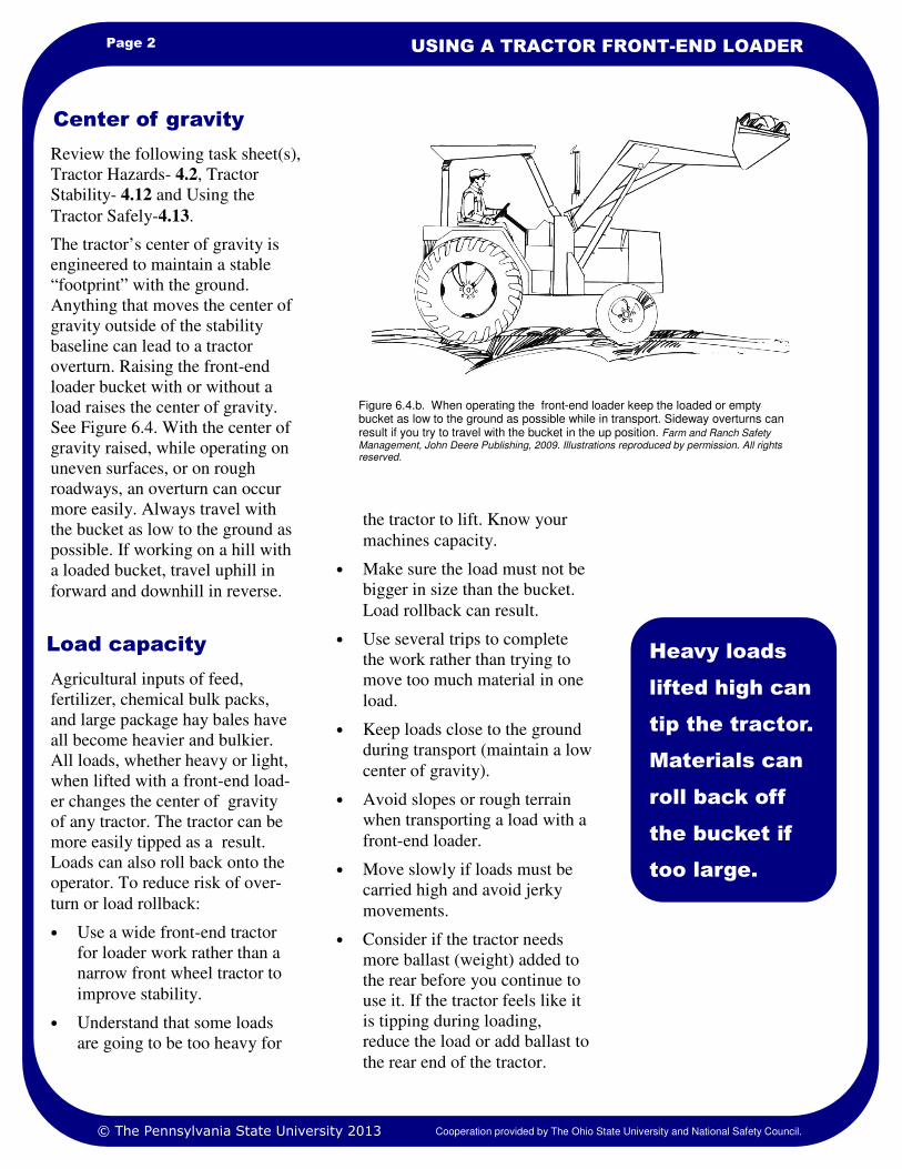
Center of gravity
Figure 6.4.b. When operating the front-end loader keep the loaded or empty bucket as low to the ground as possible while in transport. Sideway overturns can result if you try to travel with the bucket in the up position. Farm and Ranch Safety Management, John Deere Publishing, 2009. Illustrations reproduced by permission. All rights reserved.
Review the following task sheet(s),
Tractor Hazards- 4.2, Tractor
Stability- 4.12 and Using the
Tractor Safely-4.13.
The tractor’s center of gravity is
engineered to maintain a stable
“footprint” with the ground.
Anything that moves the center of
gravity outside of the stability
baseline can lead to a tractor
overturn. Raising the front-end
loader bucket with or without a
load raises the center of gravity.
See Figure 6.4. With the center of
gravity raised, while operating on
uneven surfaces, or on rough
roadways, an overturn can occur
more easily. Always travel with
the bucket as low to the ground as
possible. If working on a hill with
a loaded bucket, travel uphill in
forward and downhill in reverse.
© The Pennsylvania State University 2013 Cooperation provided by The Ohio State University and National Safety Council.
Load capacity
Agricultural inputs of feed,
fertilizer, chemical bulk packs,
and large package hay bales have
all become heavier and bulkier.
All loads, whether heavy or light,
when lifted with a front-end load-
er changes the center of gravity
of any tractor. The tractor can be
more easily tipped as a result.
Loads can also roll back onto the
operator. To reduce risk of over-
turn or load rollback:
• Use a wide front-end tractor
for loader work rather than a
narrow front wheel tractor to
improve stability.
• Understand that some loads
are going to be too heavy for
the tractor to lift. Know your
machines capacity.
• Make sure the load must not be
bigger in size than the bucket.
Load rollback can result.
• Use several trips to complete
the work rather than trying to
move too much material in one
load.
• Keep loads close to the ground
during transport (maintain a low
center of gravity).
• Avoid slopes or rough terrain
when transporting a load with a
front-end loader.
• Move slowly if loads must be
carried high and avoid jerky
movements.
• Consider if the tractor needs
more ballast (weight) added to
the rear before you continue to
use it. If the tractor feels like it
is tipping during loading,
reduce the load or add ballast to
the rear end of the tractor.
Page 3 HOSTA TASK SHEET 6.4
Work surroundings
Number 1
rule:
Keep it low;
drive slow.
Farm equipment operators must be
aware of their surroundings as they
go about the work to be done.
Before operating the front-end
loader check these points:
• Location of fellow workers
• Location of children and pets
• Location of livestock and
livestock equipment
• Location of building corners
and overhangs
• Location of utility lines
Equipment operators can become
so focused on their work they can
overlook where other persons or
animals have moved in the work
zone. Farms have children,
bystanders, and pets that may not
understand what you are doing or
anticipate your movements. Be alert
to these situations.
Buildings have received damage
from equipment operation. Be sure
that you understand the width and
height of the front-end loader and
any cargo you are carrying in it.
Avoid working too near buildings if
possible.
Most importantly know the location
of overhead power utility lines.
Maintaining a safe distance from
the utility lines. Contacting power
lines with front-end loaders or the
cargo can result in electrocution.
To avoid electrocution do not use
the front-end loader bucket to dig
into the ground unless you know
where underground utilities are
buried.
Figure 6.4.d. To prevent electrocution, lower the front end loader bucket to avoid power lines crossing the work area. Farm and Ranch Safety Management, John Deere Publishing, 2009. Illustrations reproduced by permission. All rights reserved.
© The Pennsylvania State University 2013 Cooperation provided by The Ohio State University and National Safety Council.
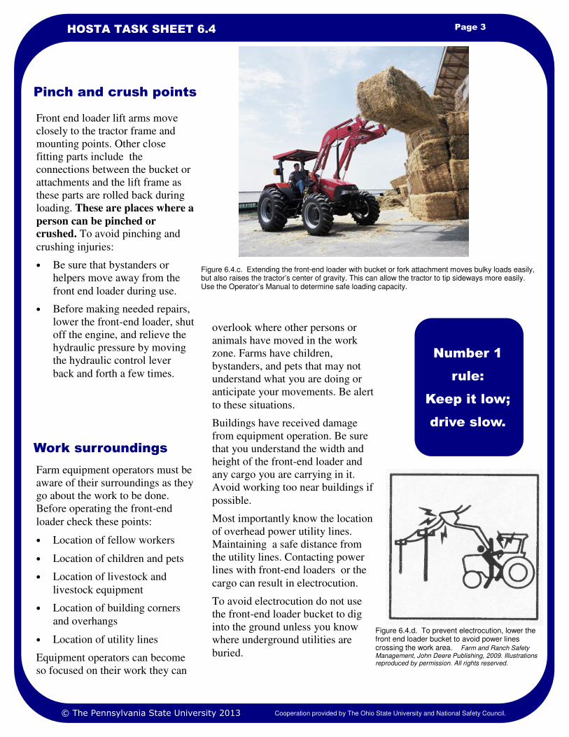
Figure 6.4.c. Extending the front-end loader with bucket or fork attachment moves bulky loads easily, but also raises the tractor’s center of gravity. This can allow the tractor to tip sideways more easily. Use the Operator’s Manual to determine safe loading capacity.
Pinch and crush points
Front end loader lift arms move
closely to the tractor frame and
mounting points. Other close
fitting parts include the
connections between the bucket or
attachments and the lift frame as
these parts are rolled back during
loading. These are places where a
person can be pinched or
crushed. To avoid pinching and
crushing injuries:
• Be sure that bystanders or
helpers move away from the
front end loader during use.
• Before making needed repairs,
lower the front-end loader, shut
off the engine, and relieve the
hydraulic pressure by moving
the hydraulic control lever
back and forth a few times.

1. Safety Management for Landscapers, Grounds-Care Busi-nesses and Golf Courses, 2001, First Edition, John Deere Publishing, Moline, Illinois
2. Operator’s Manuals from various manufacturers.
References
Page 4 USING A TRACTOR FRONT-END LOADER
1. Answer these questions.
A. What happens to a tractor’s center of gravity when you raise the front-end loader?
B. Why should the front -end loader be lowered to the ground before you leave the operator’s seat?
C. Describe a situation where load rollback can occur.
2. Become familiar with front-end loader controls by practicing the raising and lowering of the front-end loader
and then rolling the bucket or attachment forward and back. Do this until you are not confused what each
control movement does as you use it. Request that a supervisor observe your initial efforts.
3. Using a pile of sand or sawdust or mulch, practice scooping up the while observing how you approach
the pile of material. Pay attention to how much you scoop into the bucket, and how heavy it is to lift. Slowly
move the loaded material to another nearby location and dump it. Request that a supervisor observe your
initial efforts.
4. When you have mastered safety activity 2 and 3 above, repeat the activity, but place the load into a dump
truck or other container by approaching the dump truck or container slowly, raising the bucket fully,
adjusting the final approach and then dumping the load carefully without damage to the truck or container.
Safety Activities
National Safe Tractor and Machinery Operation Program The Pennsylvania State University Agricultural and Biological Engineering Department 246 Agricultural Engineering Building University Park, PA 16802 Phone: 814-865-7685 Fax: 814-863-1031 Email: [email protected]
Contact Information
Developed by WC Harshman, AM Yoder, JW Hilton and D J Murphy, The Pennsylvania State University. Version 3/2013
This material is based upon work supported by the National Institute of Food and Agriculture, U.S. Department of Agriculture, under Agreement No. 2010-41521-20839. Any opinions, findings, conclusions, or recommendations expressed in this publication are those of the author(s) and do not necessarily reflect the view of the U.S. Department of Agriculture.
Credits
© The Pennsylvania State University 2013 Cooperation provided by The Ohio State University and National Safety Council.
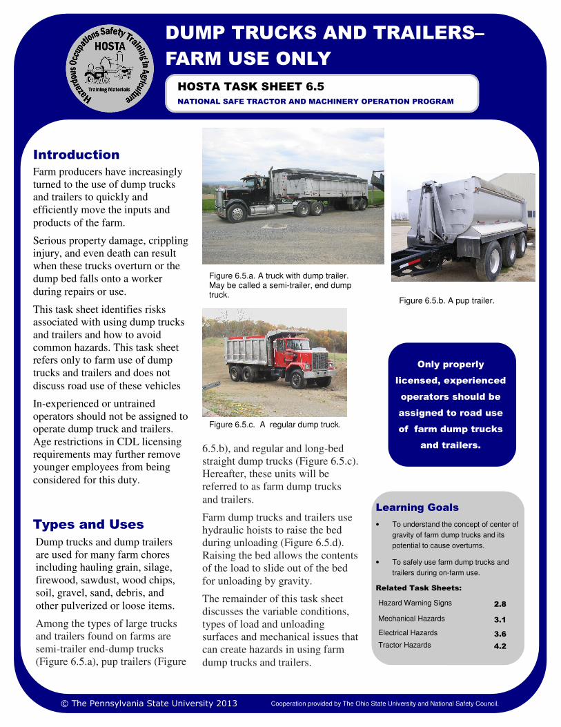
Learning Goals
• To understand the concept of center of
gravity of farm dump trucks and its
potential to cause overturns.
• To safely use farm dump trucks and
trailers during on-farm use.
Related Task Sheets:
Hazard Warning Signs 2.8
Mechanical Hazards 3.1
Tractor Hazards 4.2
Electrical Hazards 3.6
Farm producers have increasingly
turned to the use of dump trucks
and trailers to quickly and
efficiently move the inputs and
products of the farm.
Serious property damage, crippling
injury, and even death can result
when these trucks overturn or the
dump bed falls onto a worker
during repairs or use.
This task sheet identifies risks
associated with using dump trucks
and trailers and how to avoid
common hazards. This task sheet
refers only to farm use of dump
trucks and trailers and does not
discuss road use of these vehicles
In-experienced or untrained
operators should not be assigned to
operate dump truck and trailers.
Age restrictions in CDL licensing
requirements may further remove
younger employees from being
considered for this duty.
6.5.b), and regular and long-bed
straight dump trucks (Figure 6.5.c).
Hereafter, these units will be
referred to as farm dump trucks
and trailers.
Farm dump trucks and trailers use
hydraulic hoists to raise the bed
during unloading (Figure 6.5.d).
Raising the bed allows the contents
of the load to slide out of the bed
for unloading by gravity.
The remainder of this task sheet
discusses the variable conditions,
types of load and unloading
surfaces and mechanical issues that
can create hazards in using farm
dump trucks and trailers.
Introduction
Only properly
licensed, experienced
operators should be
assigned to road use
of farm dump trucks
and trailers.
DUMP TRUCKS AND TRAILERS–
FARM USE ONLY
NATIONAL SAFE TRACTOR AND MACHINERY OPERATION PROGRAM
HOSTA TASK SHEET 6.5
Dump trucks and dump trailers
are used for many farm chores
including hauling grain, silage,
firewood, sawdust, wood chips,
soil, gravel, sand, debris, and
other pulverized or loose items.
Among the types of large trucks
and trailers found on farms are
semi-trailer end-dump trucks
(Figure 6.5.a), pup trailers (Figure
Types and Uses
© The Pennsylvania State University 2013 Cooperation provided by The Ohio State University and National Safety Council.
Figure 6.5.b. A pup trailer.
Figure 6.5.c. A regular dump truck.
Figure 6.5.a. A truck with dump trailer. May be called a semi-trailer, end dump truck.
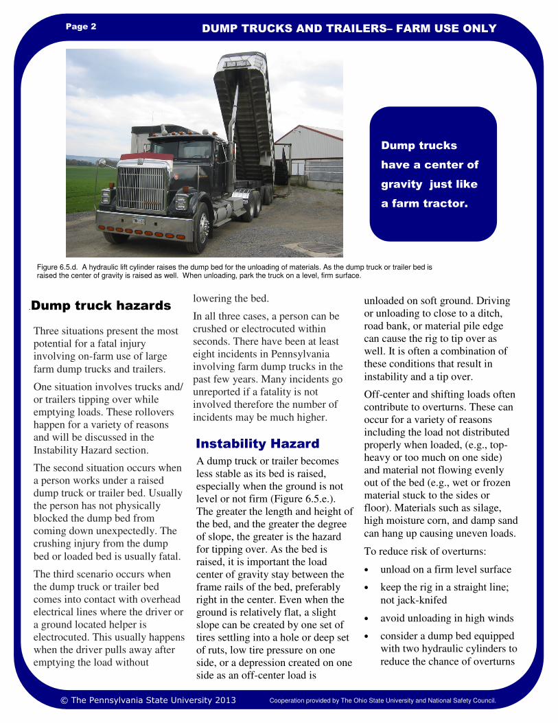
Page 2 DUMP TRUCKS AND TRAILERS– FARM USE ONLY
lowering the bed.
In all three cases, a person can be
crushed or electrocuted within
seconds. There have been at least
eight incidents in Pennsylvania
involving farm dump trucks in the
past few years. Many incidents go
unreported if a fatality is not
involved therefore the number of
incidents may be much higher.
Three situations present the most
potential for a fatal injury
involving on-farm use of large
farm dump trucks and trailers.
One situation involves trucks and/
or trailers tipping over while
emptying loads. These rollovers
happen for a variety of reasons
and will be discussed in the
Instability Hazard section.
The second situation occurs when
a person works under a raised
dump truck or trailer bed. Usually
the person has not physically
blocked the dump bed from
coming down unexpectedly. The
crushing injury from the dump
bed or loaded bed is usually fatal.
The third scenario occurs when
the dump truck or trailer bed
comes into contact with overhead
electrical lines where the driver or
a ground located helper is
electrocuted. This usually happens
when the driver pulls away after
emptying the load without
Dump trucks
have a center of
gravity just like
a farm tractor.
.Dump truck hazards
Figure 6.5.d. A hydraulic lift cylinder raises the dump bed for the unloading of materials. As the dump truck or trailer bed is raised the center of gravity is raised as well. When unloading, park the truck on a level, firm surface.
© The Pennsylvania State University 2013 Cooperation provided by The Ohio State University and National Safety Council.
Instability Hazard
A dump truck or trailer becomes
less stable as its bed is raised,
especially when the ground is not
level or not firm (Figure 6.5.e.).
The greater the length and height of
the bed, and the greater the degree
of slope, the greater is the hazard
for tipping over. As the bed is
raised, it is important the load
center of gravity stay between the
frame rails of the bed, preferably
right in the center. Even when the
ground is relatively flat, a slight
slope can be created by one set of
tires settling into a hole or deep set
of ruts, low tire pressure on one
side, or a depression created on one
side as an off-center load is
unloaded on soft ground. Driving
or unloading to close to a ditch,
road bank, or material pile edge
can cause the rig to tip over as
well. It is often a combination of
these conditions that result in
instability and a tip over.
Off-center and shifting loads often
contribute to overturns. These can
occur for a variety of reasons
including the load not distributed
properly when loaded, (e.g., top-
heavy or too much on one side)
and material not flowing evenly
out of the bed (e.g., wet or frozen
material stuck to the sides or
floor). Materials such as silage,
high moisture corn, and damp sand
can hang up causing uneven loads.
To reduce risk of overturns:
• unload on a firm level surface
• keep the rig in a straight line;
not jack-knifed
• avoid unloading in high winds
• consider a dump bed equipped
with two hydraulic cylinders to
reduce the chance of overturns
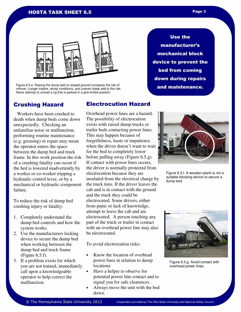
Page 3 HOSTA TASK SHEET 6.5
Use the
manufacturer’s
mechanical block
device to prevent the
bed from coming
down during repairs
and maintenance. Figure 6.5.e. Raising the dump bed on sloped ground increases the risk of rollover. Longer trailers, windy conditions, and uneven loads add to the risk. Never attempt to unload a rig that is parked in a jack-knifed position.
Workers have been crushed to
death when dump beds come down
unexpectedly. Checking an
unfamiliar noise or malfunction,
performing routine maintenance
(e.g. greasing) or repair may mean
the operator enters the space
between the dump bed and truck
frame. In this work position the risk
of a crushing fatality can occur if
the bed is lowered inadvertently by
a worker or co-worker tripping a
hydraulic control lever, or by a
mechanical or hydraulic component
failure.
To reduce the risk of dump bed
crushing injury or fatality:
1. Completely understand the
dump bed controls and how the
system works.
2. Use the manufacturers locking
device to secure the dump bed
when working between the
dump bed and truck frame
(Figure 6.5.f).
3. If a problem exists for which
you are not trained, immediately
call upon a knowledgeable
operator to help correct the
malfunction.
© The Pennsylvania State University 2013 Cooperation provided by The Ohio State University and National Safety Council.
Crushing Hazard Electrocution Hazard
Overhead power lines are a hazard.
The possibility of electrocution
exists with raised dump trucks or
trailer beds contacting power lines.
This may happen because of
forgetfulness, haste or impatience
when the driver doesn’t want to wait
for the bed to completely lower
before pulling away (Figure 6.5.g).
If contact with power lines occurs,
the driver is normally protected from
electrocution because they are
insulated from the electrical charge by
the truck tires. If the driver leaves the
cab and is in contact with the ground
and the truck they could be
electrocuted. Some drivers, either
from panic or lack of knowledge,
attempt to leave the cab and are
electrocuted. A person touching any
part of the truck or trailer in contact
with an overhead power line may also
be electrocuted.
To avoid electrocution risks:
• Know the location of overhead
power lines in relation to dump
locations
• Have a helper to observe for
potential power line contact and to
signal you for safe clearances.
• Always move the unit with the bed
down.
Figure 6.5.g. Avoid contact with overhead power lines.
Figure 6.5.f. A wooden plank is not a suitable blocking device to secure a dump bed.
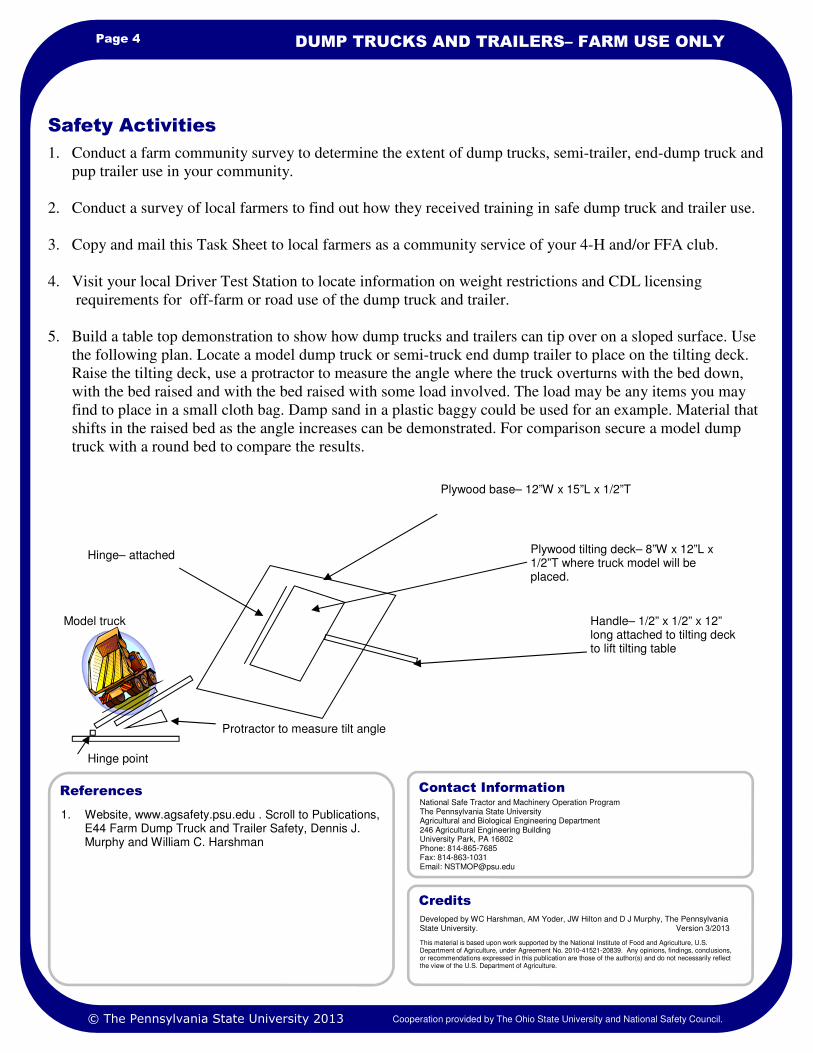
1. Website, www.agsafety.psu.edu . Scroll to Publications, E44 Farm Dump Truck and Trailer Safety, Dennis J. Murphy and William C. Harshman
References
Page 4 DUMP TRUCKS AND TRAILERS– FARM USE ONLY
1. Conduct a farm community survey to determine the extent of dump trucks, semi-trailer, end-dump truck and
pup trailer use in your community.
2. Conduct a survey of local farmers to find out how they received training in safe dump truck and trailer use.
3. Copy and mail this Task Sheet to local farmers as a community service of your 4-H and/or FFA club.
4. Visit your local Driver Test Station to locate information on weight restrictions and CDL licensing
requirements for off-farm or road use of the dump truck and trailer.
5. Build a table top demonstration to show how dump trucks and trailers can tip over on a sloped surface. Use
the following plan. Locate a model dump truck or semi-truck end dump trailer to place on the tilting deck.
Raise the tilting deck, use a protractor to measure the angle where the truck overturns with the bed down,
with the bed raised and with the bed raised with some load involved. The load may be any items you may
find to place in a small cloth bag. Damp sand in a plastic baggy could be used for an example. Material that
shifts in the raised bed as the angle increases can be demonstrated. For comparison secure a model dump
truck with a round bed to compare the results.
Safety Activities
National Safe Tractor and Machinery Operation Program The Pennsylvania State University Agricultural and Biological Engineering Department 246 Agricultural Engineering Building University Park, PA 16802 Phone: 814-865-7685 Fax: 814-863-1031 Email: [email protected]
Contact Information
Developed by WC Harshman, AM Yoder, JW Hilton and D J Murphy, The Pennsylvania State University. Version 3/2013
This material is based upon work supported by the National Institute of Food and Agriculture, U.S. Department of Agriculture, under Agreement No. 2010-41521-20839. Any opinions, findings, conclusions, or recommendations expressed in this publication are those of the author(s) and do not necessarily reflect the view of the U.S. Department of Agriculture.
Credits
© The Pennsylvania State University 2013 Cooperation provided by The Ohio State University and National Safety Council.
Hinge– attached
Plywood base– 12”W x 15”L x 1/2”T
Plywood tilting deck– 8”W x 12”L x 1/2”T where truck model will be placed.
Handle– 1/2” x 1/2” x 12” long attached to tilting deck to lift tilting table
Protractor to measure tilt angle
Model truck
Hinge point

Learning Goals
• How to conduct a pre-use safety in-
spection
• How to load and secure a load on a
trailer
• How to test electric trailer brakes be-
fore entering a public roadway
Related Task Sheets:
Tractor Stability 4.12
Operating the Tractor on Public Roads
4.14
As farms become larger and more
spread out, a farmer may own or
lease farm land several miles from
the home farm. A new employee
may be asked to tow equipment
from one farm to another.
Safe towing or transporting of
equipment on trailers is the subject
of this task sheet.
Pre-use inspection
Pre-inspection should be done in
three phases. These include:
Phase 1. Walk around the trailer to
inspect tires, damage to light
fixtures, missing tail gate pins or
other loose or damaged parts.
Phase 2. After hitching the trailer
to the towing vehicle, turn on the
vehicle lights and be sure that
trailer marking lights, turn signals,
brake lights and emergency
flashers are functional. Replace
any lamps or fuses that are burned
out before taking the trailer onto
the highway.
Phase 3. Inspect tie-down straps or
chains and chain binders. Frayed
tie-down straps or deeply nicked
chains have reduced strength and
may not be strong enough to secure
the load. Replace damaged straps
or chains immediately.
Introduction
Figure 6.6.a. This heavy duty trailer can safely handle hauling this tractor. The towing vehicle must be have a hitch rated for the load, be able to pull the load, and have sufficient braking capacity to stop the load as well.
The operator of
the towing
vehicle is
responsible for
safe towing.
LOADING AND TOWING EQUIPMENT ON
A TRAILER
NATIONAL SAFE TRACTOR AND MACHINERY OPERATION PROGRAM
HOSTA Task Sheet 6.6
The trailer must be safe to take on
the road. This means that the load
or cargo on the trailer cannot
weigh more than the trailer can
handle. Nor can the combined
weight of the trailer and the load
on it be more than the towing
vehicle can handle. The hitch on
the towing vehicle must be of the
correct size, and safety chains and
locking clips, lights, and trailer
brakes, if applicable, must be in
good condition and used properly.
Inspecting and testing equipment
before you get on the road is
important. All of these items are
discussed in the following
sections.
The operator also must use safe
driving habits while towing a
load.
Towing involves...
© The Pennsylvania State University 2013 Cooperation provided by The Ohio State University and National Safety Council.
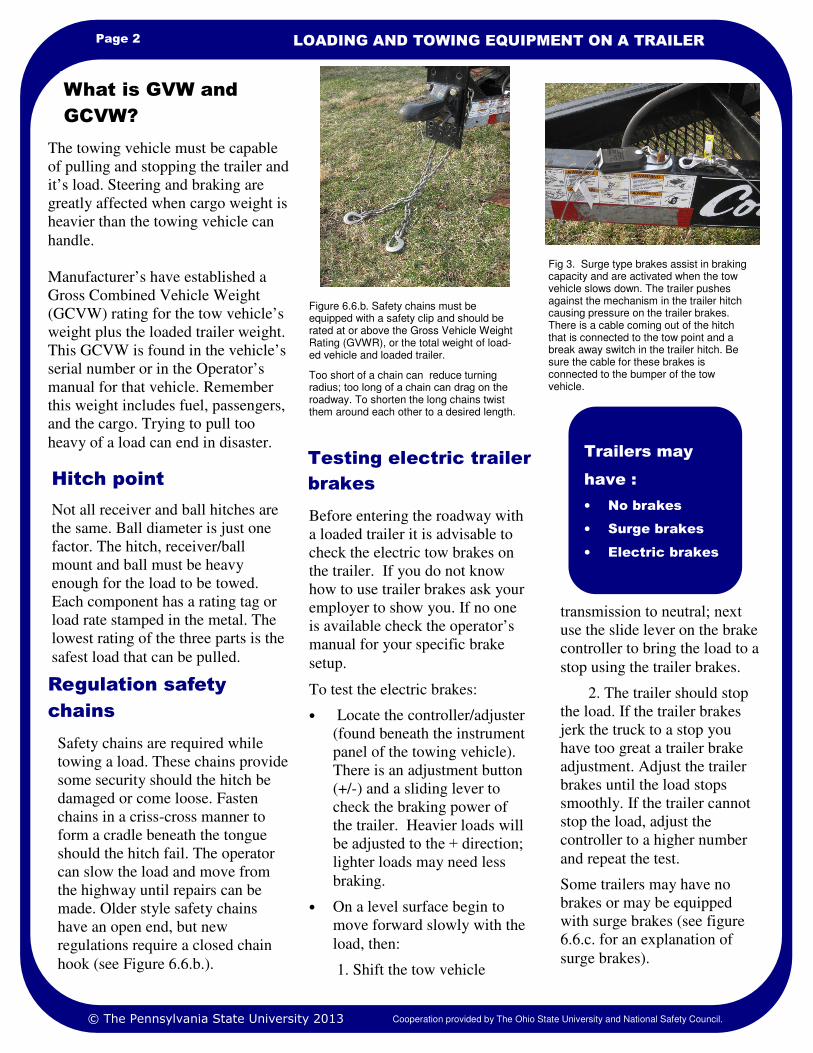
Page 2 LOADING AND TOWING EQUIPMENT ON A TRAILER
Trailers may
have :
• No brakes
• Surge brakes
• Electric brakes
The towing vehicle must be capable
of pulling and stopping the trailer and
it’s load. Steering and braking are
greatly affected when cargo weight is
heavier than the towing vehicle can
handle.
Manufacturer’s have established a
Gross Combined Vehicle Weight
(GCVW) rating for the tow vehicle’s
weight plus the loaded trailer weight.
This GCVW is found in the vehicle’s
serial number or in the Operator’s
manual for that vehicle. Remember
this weight includes fuel, passengers,
and the cargo. Trying to pull too
heavy of a load can end in disaster. Testing electric trailer
brakes
Regulation safety
chains
What is GVW and
GCVW?
© The Pennsylvania State University 2013 Cooperation provided by The Ohio State University and National Safety Council.
Safety chains are required while
towing a load. These chains provide
some security should the hitch be
damaged or come loose. Fasten
chains in a criss-cross manner to
form a cradle beneath the tongue
should the hitch fail. The operator
can slow the load and move from
the highway until repairs can be
made. Older style safety chains
have an open end, but new
regulations require a closed chain
hook (see Figure 6.6.b.).
Before entering the roadway with
a loaded trailer it is advisable to
check the electric tow brakes on
the trailer. If you do not know
how to use trailer brakes ask your
employer to show you. If no one
is available check the operator’s
manual for your specific brake
setup.
To test the electric brakes:
• Locate the controller/adjuster
(found beneath the instrument
panel of the towing vehicle).
There is an adjustment button
(+/-) and a sliding lever to
check the braking power of
the trailer. Heavier loads will
be adjusted to the + direction;
lighter loads may need less
braking.
• On a level surface begin to
move forward slowly with the
load, then:
1. Shift the tow vehicle
transmission to neutral; next
use the slide lever on the brake
controller to bring the load to a
stop using the trailer brakes.
2. The trailer should stop
the load. If the trailer brakes
jerk the truck to a stop you
have too great a trailer brake
adjustment. Adjust the trailer
brakes until the load stops
smoothly. If the trailer cannot
stop the load, adjust the
controller to a higher number
and repeat the test.
Some trailers may have no
brakes or may be equipped
with surge brakes (see figure
6.6.c. for an explanation of
surge brakes).
Figure 6.6.b. Safety chains must be equipped with a safety clip and should be rated at or above the Gross Vehicle Weight Rating (GVWR), or the total weight of load-ed vehicle and loaded trailer.
Too short of a chain can reduce turning radius; too long of a chain can drag on the roadway. To shorten the long chains twist them around each other to a desired length.
Fig 3. Surge type brakes assist in braking capacity and are activated when the tow vehicle slows down. The trailer pushes against the mechanism in the trailer hitch causing pressure on the trailer brakes. There is a cable coming out of the hitch that is connected to the tow point and a break away switch in the trailer hitch. Be sure the cable for these brakes is connected to the bumper of the tow vehicle.
Hitch point
Not all receiver and ball hitches are
the same. Ball diameter is just one
factor. The hitch, receiver/ball
mount and ball must be heavy
enough for the load to be towed.
Each component has a rating tag or
load rate stamped in the metal. The
lowest rating of the three parts is the
safest load that can be pulled.
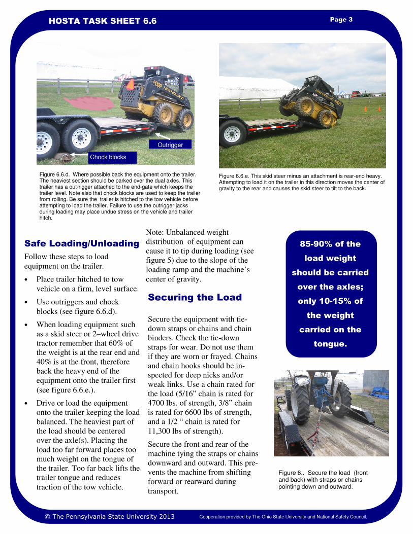
Page 3 HOSTA TASK SHEET 6.6
Note: Unbalanced weight
distribution of equipment can
cause it to tip during loading (see
figure 5) due to the slope of the
loading ramp and the machine’s
center of gravity.
Follow these steps to load
equipment on the trailer.
• Place trailer hitched to tow
vehicle on a firm, level surface.
• Use outriggers and chock
blocks (see figure 6.6.d).
• When loading equipment such
as a skid steer or 2–wheel drive
tractor remember that 60% of
the weight is at the rear end and
40% is at the front, therefore
back the heavy end of the
equipment onto the trailer first
(see figure 6.6.e.).
• Drive or load the equipment
onto the trailer keeping the load
balanced. The heaviest part of
the load should be centered
over the axle(s). Placing the
load too far forward places too
much weight on the tongue of
the trailer. Too far back lifts the
trailer tongue and reduces
traction of the tow vehicle.
Safe Loading/Unloading
Figure 6.6.d. Where possible back the equipment onto the trailer. The heaviest section should be parked over the dual axles. This trailer has a out-rigger attached to the end-gate which keeps the trailer level. Note also that chock blocks are used to keep the trailer from rolling. Be sure the trailer is hitched to the tow vehicle before attempting to load the trailer. Failure to use the outrigger jacks during loading may place undue stress on the vehicle and trailer hitch.
85-90% of the
load weight
should be carried
over the axles;
only 10-15% of
the weight
carried on the
tongue.
Figure 6.6.e. This skid steer minus an attachment is rear-end heavy. Attempting to load it on the trailer in this direction moves the center of gravity to the rear and causes the skid steer to tilt to the back.
© The Pennsylvania State University 2013 Cooperation provided by The Ohio State University and National Safety Council.
Securing the Load
Secure the equipment with tie-
down straps or chains and chain
binders. Check the tie-down
straps for wear. Do not use them
if they are worn or frayed. Chains
and chain hooks should be in-
spected for deep nicks and/or
weak links. Use a chain rated for
the load (5/16” chain is rated for
4700 lbs. of strength, 3/8” chain
is rated for 6600 lbs of strength,
and a 1/2 “ chain is rated for
11,300 lbs of strength).
Secure the front and rear of the
machine tying the straps or chains
downward and outward. This pre-
vents the machine from shifting
forward or rearward during
transport.
Figure 6.. Secure the load (front and back) with straps or chains pointing down and outward.
Chock blocks
Outrigger
1. Safety Management for Landscapers, Grounds-Care Businesses, and Golf Courses, John Deere Publishing, 2001.
2. Internet search for trailer safety, www.howstuffworks.com
3. Internet search for trailer safety for agriculture,
www.nycamh.com/resources/safety
References
Page 4 LOADING AND TOWING EQUIPMENT ON A TRAILER
1. Ask a trained individual to demonstrate how to drive a tractor or skid steer onto a trailer for you. Then
perform this task under their supervision. Observe the position of the load as it is placed over the axle(s) of
the trailer. Remember that 85-90% of the weight must be over the axle(s).
2. Ask the same individual in Activity 1 to demonstrate the correct way to secure a load on a trailer using tie-
down straps or chain and chain binders. Repeat this task with their supervision.
3. What is the GVW of the tow vehicle you will use? What is the GVW of the trailer you will be using? Add
the two GVW weights together for the GCVW. Check the GCVW weight you have calculated and compare
with the information found on the tow vehicle serial number plate (usually found inside the door frame). Is
the total weight within the limits shown on the serial number plate?
4. Federal regulations include Commercial Drivers License (CDL) requirements for trucks and trailers over a
certain CGVW. Some exemptions may apply to agriculture. Use an Internet search engine to find if your
State has other requirements or exemptions.
5. What is the weight of the load you are about to tow? If only 10-15% of that weight can be on the tongue of
the trailer how much weight can be on the tongue? If a heavy enough set of wheel-type scales (scale beneath
each wheel) are available, load the equipment on the trailer, chock the wheels, place one scale beneath the
jack, disconnect from the tow vehicle and raise the tongue until the loaded trailer is setting on the scales.
What is the weight you have on the tongue of the trailer?
Safety Activities
National Safe Tractor and Machinery Operation Program The Pennsylvania State University Agricultural and Biological Engineering Department 246 Agricultural Engineering Building University Park, PA 16802 Phone: 814-865-7685 Fax: 814-863-1031 Email: [email protected]
Contact Information
Developed by WC Harshman, AM Yoder, JW Hilton and D J Murphy, The Pennsylvania State University. Version 3/2013
This material is based upon work supported by the National Institute of Food and Agriculture, U.S. Department of Agriculture, under Agreement No.2010-41521-20839. Any opinions, findings, conclusions, or recommendations expressed in this publication are those of the author(s) and do not necessarily reflect the view of the U.S. Department of Agriculture.
Credits
© The Pennsylvania State University 2013 Cooperation provided by The Ohio State University and National Safety Council.
Safety Note: Towing/Trailering of engine driven equipment equipped with a turbocharger may require
blocking of the airflow into the turbocharger through the exhaust. While it is rare, expensive turbo-
chargers have been damaged by transporting tractors with the exhaust pipe facing the direction of travel.
Damage occurs should an exhaust valve in the open position allow air to flow through the turbocharger,
freely rotating the turbocharger blades. Since the turbocharger is not being operated by engine power, tur-
bocharger bearings can burn due to no lubrication being pumped to those turning parts.

Learning Goals
• To learn how an auger and elevator
operates
• To identify auger and elevator hazards
and how to avoid an entanglement or electrocution.
Talk to an older farmer and they
will tell you about shoveling corn
into the corn crib or feed grinder.
Those days are over. Augers and
elevators quickly and efficiently
move grain, processed feeds, and
forages to improve our farm
productivity. These devices have
moving parts with pinch points and
wrap points that must be guarded.
After years of use, guards may be
damaged or missing and
homemade elevators exist that
have never been guarded. The risk
of being pulled into and entangled
in the moving parts of unguarded
machines is high.
This task sheet provides facts that
may help you avoid an injury or
fatality due to auger and elevator
hazards. Review Task Sheet 3.1,
Mechanical Hazards.
Safely guarding
augers
Engineering Standards by
theAmerican Society of
Agricultural and Biological
Engineers –ASABE) call for
exposed auger flights to be guarded
as follows:
• Guards are to cover the top
180O of the inlet area and
extend a minimum of 2.5
inches above and below the
exposed auger flights.
• Openings in the guard for the
free flow of material shall be
no larger than 4.75 inches for
the largest dimension opening
and the area of the opening
shall be no larger than 10
square inches.
• The guard should be no closer
than 2.5 inches to the rotating
auger flights and able to
support a 270 lb. person.
• Drag-type augers and grating
type guards are to have these
standard dimensions as well.
In addition, safety signs should be
in place to inform the operator of
the rotating parts hazards and to
warn against modification or
removal of guards.
With years of use auger guards can
become damaged. Damaged auger
guards increase the risk that an
injury or fatality can occur. If
auger guards are damaged or
missing report it to the employer or
supervisor.
Introduction
Figure 6.8.a. Augers are found in many places. Augers move grain and feedstuffs into bins and processors and carry these materials to feed carts, grinders-mixers, and to feed bunks. The moving parts can pull a victim into the machine. Augers should be guarded as shown. Auger guards must be kept in safe condition. The picture shows how effective the guard can be at protecting the user.
Augers must be
guarded. Keep
guards in safe
condition.
AUGERS AND ELEVATORS
NATIONAL SAFE TRACTOR AND MACHINERY OPERATION PROGRAM
HOSTA Task Sheet 6.8
The auger is a shaft with a metal
or hard plastic, screw-thread
fluting attached. The end of the
auger can be placed into a grain
pile, bin, or wagon and begin to
move material very quickly. The
turning part (auger) and the auger
tube move close enough together
to be able to snag loose clothing,
feet or hands. Entanglement,
amputation or both can occur.
Elevator belts and pulleys or
chains and sprockets can entangle
the operator if guards are not in
place.
How an auger works
© The Pennsylvania State University 2013 Cooperation provided by The Ohio State University and National Safety Council.
Reaction Time 2.3
Mechanical Hazards 3.1
Grain Bins 3.10
Electrical Hazards 3.6
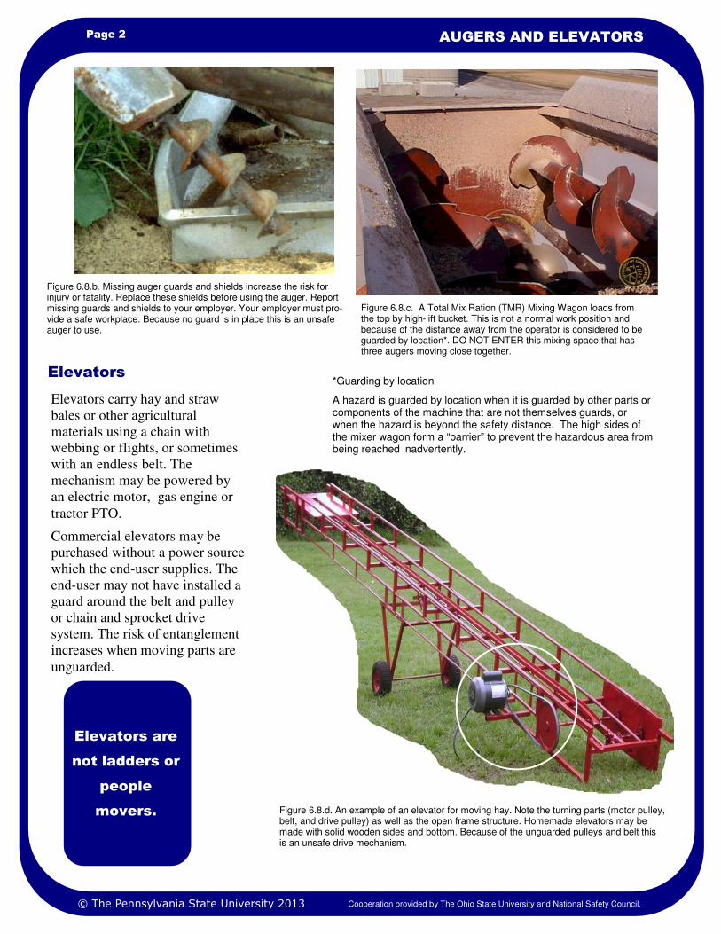
Page 2 AUGERS AND ELEVATORS
Elevators
Figure 6.8.b. Missing auger guards and shields increase the risk for injury or fatality. Replace these shields before using the auger. Report missing guards and shields to your employer. Your employer must pro-vide a safe workplace. Because no guard is in place this is an unsafe auger to use.
Figure 6.8.c. A Total Mix Ration (TMR) Mixing Wagon loads from the top by high-lift bucket. This is not a normal work position and because of the distance away from the operator is considered to be guarded by location*. DO NOT ENTER this mixing space that has three augers moving close together.
Elevators carry hay and straw
bales or other agricultural
materials using a chain with
webbing or flights, or sometimes
with an endless belt. The
mechanism may be powered by
an electric motor, gas engine or
tractor PTO.
Commercial elevators may be
purchased without a power source
which the end-user supplies. The
end-user may not have installed a
guard around the belt and pulley
or chain and sprocket drive
system. The risk of entanglement
increases when moving parts are
unguarded.
Elevators are
not ladders or
people
movers.
© The Pennsylvania State University 2013 Cooperation provided by The Ohio State University and National Safety Council.
Figure 6.8.d. An example of an elevator for moving hay. Note the turning parts (motor pulley, belt, and drive pulley) as well as the open frame structure. Homemade elevators may be made with solid wooden sides and bottom. Because of the unguarded pulleys and belt this is an unsafe drive mechanism.
*Guarding by location
A hazard is guarded by location when it is guarded by other parts or components of the machine that are not themselves guards, or when the hazard is beyond the safety distance. The high sides of the mixer wagon form a “barrier” to prevent the hazardous area from being reached inadvertently.
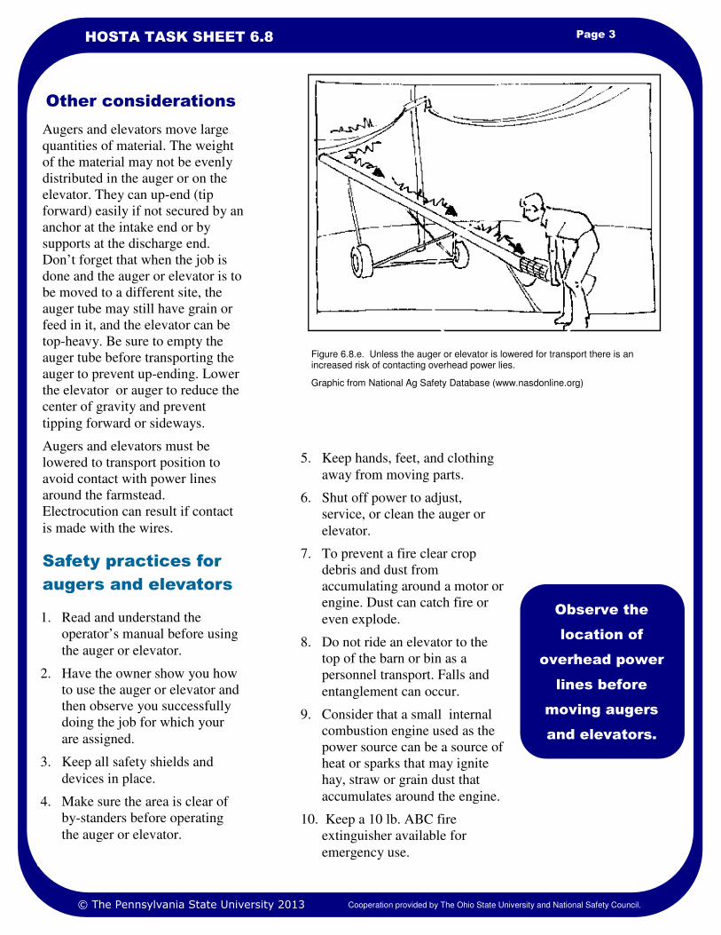
Page 3 HOSTA TASK SHEET 6.8
Augers and elevators move large
quantities of material. The weight
of the material may not be evenly
distributed in the auger or on the
elevator. They can up-end (tip
forward) easily if not secured by an
anchor at the intake end or by
supports at the discharge end.
Don’t forget that when the job is
done and the auger or elevator is to
be moved to a different site, the
auger tube may still have grain or
feed in it, and the elevator can be
top-heavy. Be sure to empty the
auger tube before transporting the
auger to prevent up-ending. Lower
the elevator or auger to reduce the
center of gravity and prevent
tipping forward or sideways.
Augers and elevators must be
lowered to transport position to
avoid contact with power lines
around the farmstead.
Electrocution can result if contact
is made with the wires.
Observe the
location of
overhead power
lines before
moving augers
and elevators.
Safety practices for
augers and elevators
1. Read and understand the
operator’s manual before using
the auger or elevator.
2. Have the owner show you how
to use the auger or elevator and
then observe you successfully
doing the job for which your
are assigned.
3. Keep all safety shields and
devices in place.
4. Make sure the area is clear of
by-standers before operating
the auger or elevator.
5. Keep hands, feet, and clothing
away from moving parts.
6. Shut off power to adjust,
service, or clean the auger or
elevator.
7. To prevent a fire clear crop
debris and dust from
accumulating around a motor or
engine. Dust can catch fire or
even explode.
8. Do not ride an elevator to the
top of the barn or bin as a
personnel transport. Falls and
entanglement can occur.
9. Consider that a small internal
combustion engine used as the
power source can be a source of
heat or sparks that may ignite
hay, straw or grain dust that
accumulates around the engine.
10. Keep a 10 lb. ABC fire
extinguisher available for
emergency use.
© The Pennsylvania State University 2013 Cooperation provided by The Ohio State University and National Safety Council.
Other considerations
Figure 6.8.e. Unless the auger or elevator is lowered for transport there is an increased risk of contacting overhead power lies.
Graphic from National Ag Safety Database (www.nasdonline.org)
1. Farm and Ranch Safety Management, John Deere Publishing, 2009.
2. American Society of Agricultural and Biological Engineers (ASABE), ASAE S361.3 (Revised 2005) Safety for Portable Agricultural Auger Conveying Equipment.
3. www.nasdonline.org. Type in Search Box to locate auger and elevator safety information.
4. American Society of Agricultural and Biological Engineers (ASABE), ANSI/ASAE S493.1(Revised 2008) Guarding for Agricultural Equipment.
References
Page 4 AUGERS AND ELEVATORS
1. Using an Internet search engine of your choice, search for agricultural injuries and/or fatalities involving an
auger or elevator. Analyze 3 of these incidents to find if the incidents had anything in common. Compare
the age of victim, machine condition, time of year, and any other factor in your analysis. A good source of
information is found at www.agsafety.psu.edu. Look for the annual farm fatality reports in this website
hosted by the Penn State University, Department of Agricultural and Biological Engineering, Agricultural
Safety and Health Program.
2. Conduct a safety check on the augers and elevators on your farm, a relative’s farm, or a neighbor’s farm
(with their permission and supervision if possible). Using the ASABE Standards (page 1) and the safety
recommendations (page 2) information given develop a report with pictures that could be given to the owner
or presented to your agriculture class or 4-H club members.
3. Solve this problem. If a 10 inch auger can move 65 bushels of grain per minute, how many bushels of grain
will a 7.5 inch auger move in one minute. Show your work in this ratio, or proportion-type calculation.
Safety Activities
National Safe Tractor and Machinery Operation Program The Pennsylvania State University Agricultural and Biological Engineering Department 246 Agricultural Engineering Building University Park, PA 16802 Phone: 814-865-7685 Fax: 814-863-1031 Email: [email protected]
Contact Information
Developed by WC Harshman, AM Yoder, JW Hilton and D J Murphy, The Pennsylvania State University. Version 3/2013
This material is based upon work supported by the National Institute of Food and Agriculture, U.S. Department of Agriculture, under Agreement No. 2010-41521-20839. Any opinions, findings, conclusions, or recommendations expressed in this publication are those of the author(s) and do not necessarily reflect the view of the U.S. Department of Agriculture.
Credits
© The Pennsylvania State University 2013 Cooperation provided by The Ohio State University and National Safety Council.
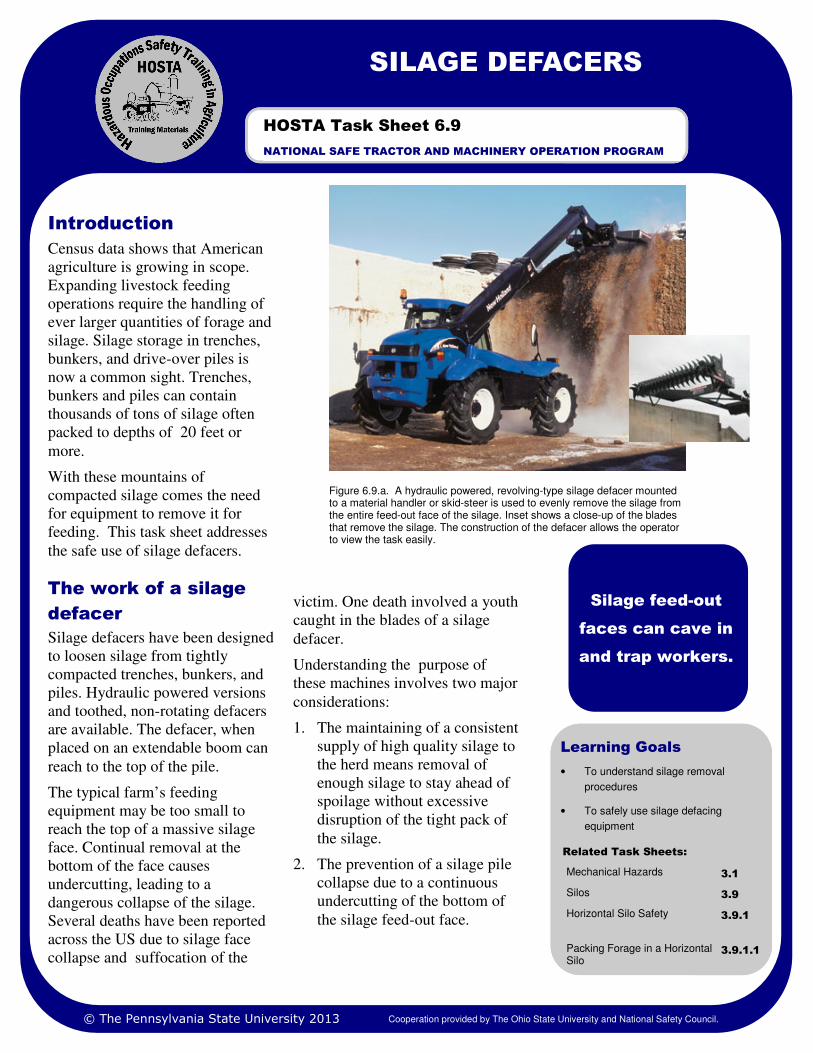
SILAGE DEFACERS
Learning Goals
• To understand silage removal
procedures
• To safely use silage defacing
equipment
Census data shows that American
agriculture is growing in scope.
Expanding livestock feeding
operations require the handling of
ever larger quantities of forage and
silage. Silage storage in trenches,
bunkers, and drive-over piles is
now a common sight. Trenches,
bunkers and piles can contain
thousands of tons of silage often
packed to depths of 20 feet or
more.
With these mountains of
compacted silage comes the need
for equipment to remove it for
feeding. This task sheet addresses
the safe use of silage defacers.
The work of a silage
defacer
Silage defacers have been designed
to loosen silage from tightly
compacted trenches, bunkers, and
piles. Hydraulic powered versions
and toothed, non-rotating defacers
are available. The defacer, when
placed on an extendable boom can
reach to the top of the pile.
The typical farm’s feeding
equipment may be too small to
reach the top of a massive silage
face. Continual removal at the
bottom of the face causes
undercutting, leading to a
dangerous collapse of the silage.
Several deaths have been reported
across the US due to silage face
collapse and suffocation of the
victim. One death involved a youth
caught in the blades of a silage
defacer.
Understanding the purpose of
these machines involves two major
considerations:
1. The maintaining of a consistent
supply of high quality silage to
the herd means removal of
enough silage to stay ahead of
spoilage without excessive
disruption of the tight pack of
the silage.
2. The prevention of a silage pile
collapse due to a continuous
undercutting of the bottom of
the silage feed-out face.
Introduction
Figure 6.9.a. A hydraulic powered, revolving-type silage defacer mounted to a material handler or skid-steer is used to evenly remove the silage from the entire feed-out face of the silage. Inset shows a close-up of the blades that remove the silage. The construction of the defacer allows the operator to view the task easily.
Silage feed-out
faces can cave in
and trap workers.
NATIONAL SAFE TRACTOR AND MACHINERY OPERATION PROGRAM
HOSTA Task Sheet 6.9
Related Task Sheets:
Mechanical Hazards 3.1
Silos 3.9
Packing Forage in a Horizontal Silo
3.9.1.1
Horizontal Silo Safety 3.9.1
© The Pennsylvania State University 2013 Cooperation provided by The Ohio State University and National Safety Council.
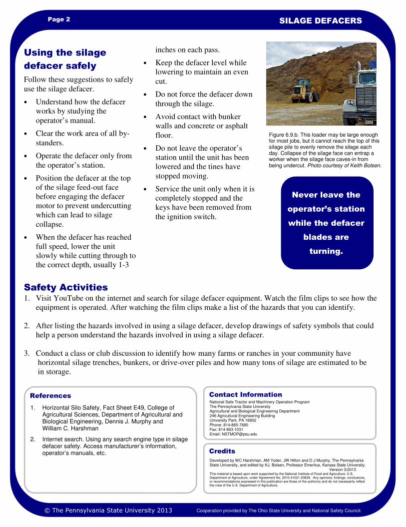
Page 2 SILAGE DEFACERS
1. Horizontal Silo Safety, Fact Sheet E49, College of Agricultural Sciences, Department of Agricultural and Biological Engineering, Dennis J. Murphy and William C. Harshman
2. Internet search. Using any search engine type in silage defacer safety. Access manufacturer’s information, operator’s manuals, etc.
References
1. Visit YouTube on the internet and search for silage defacer equipment. Watch the film clips to see how the
equipment is operated. After watching the film clips make a list of the hazards that you can identify.
2. After listing the hazards involved in using a silage defacer, develop drawings of safety symbols that could
help a person understand the hazards involved in using a silage defacer.
3. Conduct a class or club discussion to identify how many farms or ranches in your community have
horizontal silage trenches, bunkers, or drive-over piles and how many tons of silage are estimated to be
in storage.
Safety Activities
inches on each pass.
• Keep the defacer level while
lowering to maintain an even
cut.
• Do not force the defacer down
through the silage.
• Avoid contact with bunker
walls and concrete or asphalt
floor.
• Do not leave the operator’s
station until the unit has been
lowered and the tines have
stopped moving.
• Service the unit only when it is
completely stopped and the
keys have been removed from
the ignition switch.
Follow these suggestions to safely
use the silage defacer.
• Understand how the defacer
works by studying the
operator’s manual.
• Clear the work area of all by-
standers.
• Operate the defacer only from
the operator’s station.
• Position the defacer at the top
of the silage feed-out face
before engaging the defacer
motor to prevent undercutting
which can lead to silage
collapse.
• When the defacer has reached
full speed, lower the unit
slowly while cutting through to
the correct depth, usually 1-3
Using the silage
defacer safely
Never leave the
operator’s station
while the defacer
blades are
turning.
Figure 6.9.b. This loader may be large enough for most jobs, but it cannot reach the top of this silage pile to evenly remove the silage each day. Collapse of the silage face can entrap a worker when the silage face caves-in from being undercut. Photo courtesy of Keith Bolsen.
National Safe Tractor and Machinery Operation Program The Pennsylvania State University Agricultural and Biological Engineering Department 246 Agricultural Engineering Building University Park, PA 16802 Phone: 814-865-7685 Fax: 814-863-1031 Email: [email protected]
Contact Information
Developed by WC Harshman, AM Yoder, JW Hilton and D J Murphy, The Pennsylvania State University, and edited by KJ. Bolsen, Professor Emeritus, Kansas State University. Version 3/2013 This material is based upon work supported by the National Institute of Food and Agriculture, U.S. Department of Agriculture, under Agreement No. 2010-41521-20839. Any opinions, findings, conclusions, or recommendations expressed in this publication are those of the author(s) and do not necessarily reflect the view of the U.S. Department of Agriculture.
Credits
© The Pennsylvania State University 2013 Cooperation provided by The Ohio State University and National Safety Council.
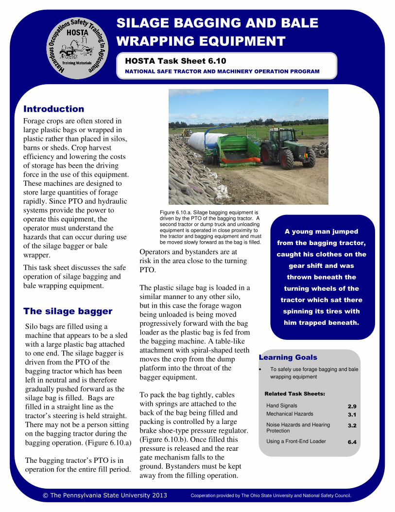
Learning Goals
• To safely use forage bagging and bale
wrapping equipment
Related Task Sheets:
Hand Signals 2.9
Mechanical Hazards 3.1
Noise Hazards and Hearing Protection
3.2
Using a Front-End Loader 6.4
Forage crops are often stored in
large plastic bags or wrapped in
plastic rather than placed in silos,
barns or sheds. Crop harvest
efficiency and lowering the costs
of storage has been the driving
force in the use of this equipment.
These machines are designed to
store large quantities of forage
rapidly. Since PTO and hydraulic
systems provide the power to
operate this equipment, the
operator must understand the
hazards that can occur during use
of the silage bagger or bale
wrapper.
This task sheet discusses the safe
operation of silage bagging and
bale wrapping equipment.
Operators and bystanders are at
risk in the area close to the turning
PTO.
The plastic silage bag is loaded in a
similar manner to any other silo,
but in this case the forage wagon
being unloaded is being moved
progressively forward with the bag
loader as the plastic bag is fed from
the bagging machine. A table-like
attachment with spiral-shaped teeth
moves the crop from the dump
platform into the throat of the
bagger equipment.
To pack the bag tightly, cables
with springs are attached to the
back of the bag being filled and
packing is controlled by a large
brake shoe-type pressure regulator.
(Figure 6.10.b). Once filled this
pressure is released and the rear
gate mechanism falls to the
ground. Bystanders must be kept
away from the filling operation.
Introduction
Figure 6.10.a. Silage bagging equipment is driven by the PTO of the bagging tractor. A second tractor or dump truck and unloading equipment is operated in close proximity to the tractor and bagging equipment and must be moved slowly forward as the bag is filled.
A young man jumped
from the bagging tractor,
caught his clothes on the
gear shift and was
thrown beneath the
turning wheels of the
tractor which sat there
spinning its tires with
him trapped beneath.
SILAGE BAGGING AND BALE
WRAPPING EQUIPMENT
NATIONAL SAFE TRACTOR AND MACHINERY OPERATION PROGRAM
HOSTA Task Sheet 6.10
Silo bags are filled using a
machine that appears to be a sled
with a large plastic bag attached
to one end. The silage bagger is
driven from the PTO of the
bagging tractor which has been
left in neutral and is therefore
gradually pushed forward as the
silage bag is filled. Bags are
filled in a straight line as the
tractor’s steering is held straight.
There may not be a person sitting
on the bagging tractor during the
bagging operation. (Figure 6.10.a)
The bagging tractor’s PTO is in
operation for the entire fill period.
The silage bagger
© The Pennsylvania State University 2013 Cooperation provided by The Ohio State University and National Safety Council.
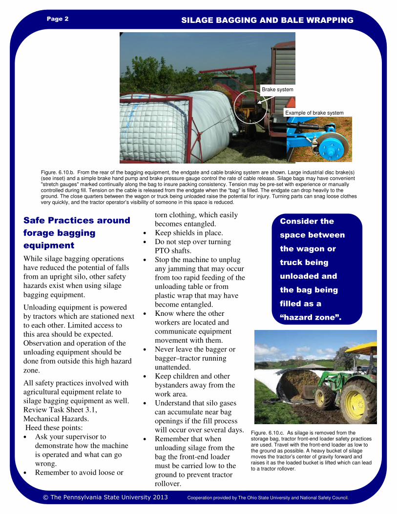
Page 2 SILAGE BAGGING AND BALE WRAPPING
torn clothing, which easily
becomes entangled.
• Keep shields in place.
• Do not step over turning
PTO shafts.
• Stop the machine to unplug
any jamming that may occur
from too rapid feeding of the
unloading table or from
plastic wrap that may have
become entangled.
• Know where the other
workers are located and
communicate equipment
movement with them.
• Never leave the bagger or
bagger–tractor running
unattended.
• Keep children and other
bystanders away from the
work area.
• Understand that silo gases
can accumulate near bag
openings if the fill process
will occur over several days.
• Remember that when
unloading silage from the
bag the front-end loader
must be carried low to the
ground to prevent tractor
rollover.
While silage bagging operations
have reduced the potential of falls
from an upright silo, other safety
hazards exist when using silage
bagging equipment.
Unloading equipment is powered
by tractors which are stationed next
to each other. Limited access to
this area should be expected.
Observation and operation of the
unloading equipment should be
done from outside this high hazard
zone.
All safety practices involved with
agricultural equipment relate to
silage bagging equipment as well.
Review Task Sheet 3.1,
Mechanical Hazards.
Heed these points:
• Ask your supervisor to
demonstrate how the machine
is operated and what can go
wrong.
• Remember to avoid loose or
Safe Practices around
forage bagging
equipment
Consider the
space between
the wagon or
truck being
unloaded and
the bag being
filled as a
“hazard zone”.
Figure. 6.10.c. As silage is removed from the storage bag, tractor front-end loader safety practices are used. Travel with the front-end loader as low to the ground as possible. A heavy bucket of silage moves the tractor’s center of gravity forward and raises it as the loaded bucket is lifted which can lead to a tractor rollover.
Figure. 6.10.b. From the rear of the bagging equipment, the endgate and cable braking system are shown. Large industrial disc brake(s) (see inset) and a simple brake hand pump and brake pressure gauge control the rate of cable release. Silage bags may have convenient "stretch gauges" marked continually along the bag to insure packing consistency. Tension may be pre-set with experience or manually controlled during fill. Tension on the cable is released from the endgate when the “bag” is filled. The endgate can drop heavily to the ground. The close quarters between the wagon or truck being unloaded raise the potential for injury. Turning parts can snag loose clothes very quickly, and the tractor operator’s visibility of someone in this space is reduced.
© The Pennsylvania State University 2013
Brake system
Example of brake system
Cooperation provided by The Ohio State University and National Safety Council.
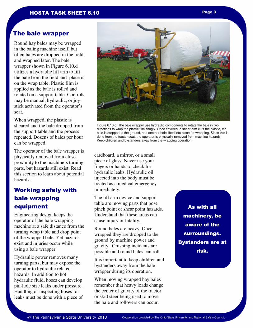
Page 3 HOSTA TASK SHEET 6.10
The bale wrapper
As with all
machinery, be
aware of the
surroundings.
Bystanders are at
risk.
Figure 6.10.d. The bale wrapper use hydraulic components to rotate the bale in two directions to wrap the plastic film snugly. Once covered, a shear arm cuts the plastic, the bale is dropped to the ground, and another bale lifted into place for wrapping. Since this is done from the tractor seat, the operator is physically removed from machine hazards. Keep children and bystanders away from the wrapping operation.
Round hay bales may be wrapped
in the baling machine itself, but
often bales are dropped in the field
and wrapped later. The bale
wrapper shown in Figure 6.10.d
utilizes a hydraulic lift arm to lift
the bale from the field and place it
on the wrap table. Plastic film is
applied as the bale is rolled and
rotated on a support table. Controls
may be manual, hydraulic, or joy-
stick activated from the operator’s
seat.
When wrapped, the plastic is
sheared and the bale dropped from
the support table and the process
repeated. Dozens of bales per hour
can be wrapped.
The operator of the bale wrapper is
physically removed from close
proximity to the machine’s turning
parts, but hazards still exist. Read
this section to learn about potential
hazards.
Working safely with
bale wrapping
equipment
Engineering design keeps the
operator of the bale wrapping
machine at a safe distance from the
turning wrap table and drop point
of the wrapped bale. Yet hazards
exist and injuries occur while
using a bale wrapper.
Hydraulic power removes many
turning parts, but may expose the
operator to hydraulic related
hazards. In addition to hot
hydraulic fluid, hoses can develop
pin-hole size leaks under pressure.
Handling or inspecting hoses for
leaks must be done with a piece of
cardboard, a mirror, or a small
piece of glass. Never use your
fingers or hands to check for
hydraulic leaks. Hydraulic oil
injected into the body must be
treated as a medical emergency
immediately.
The lift arm device and support
table are moving parts that pose
pinch point or shear point hazards.
Understand that these areas can
cause injury or fatality.
Round bales are heavy. Once
wrapped they are dropped to the
ground by machine power and
gravity. Crushing incidents are
possible and round bales can roll.
It is important to keep children and
bystanders away from the bale
wrapper during its operation.
When moving wrapped hay bales
remember that heavy loads change
the center of gravity of the tractor
or skid steer being used to move
the bale and rollovers can occur.
© The Pennsylvania State University 2013 Cooperation provided by The Ohio State University and National Safety Council.
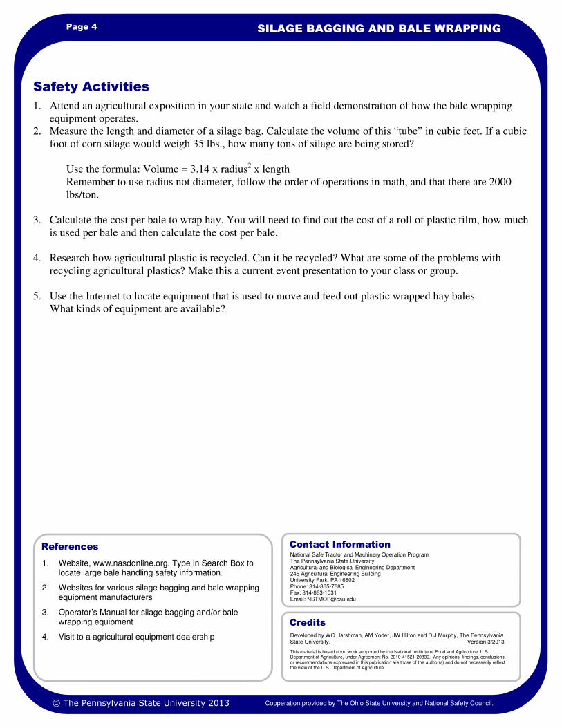
1. Website, www.nasdonline.org. Type in Search Box to locate large bale handling safety information.
2. Websites for various silage bagging and bale wrapping equipment manufacturers
3. Operator’s Manual for silage bagging and/or bale wrapping equipment
4. Visit to a agricultural equipment dealership
References
Page 4 SILAGE BAGGING AND BALE WRAPPING
1. Attend an agricultural exposition in your state and watch a field demonstration of how the bale wrapping
equipment operates.
2. Measure the length and diameter of a silage bag. Calculate the volume of this “tube” in cubic feet. If a cubic
foot of corn silage would weigh 35 lbs., how many tons of silage are being stored?
Use the formula: Volume = 3.14 x radius2 x length
Remember to use radius not diameter, follow the order of operations in math, and that there are 2000
lbs/ton.
3. Calculate the cost per bale to wrap hay. You will need to find out the cost of a roll of plastic film, how much
is used per bale and then calculate the cost per bale.
4. Research how agricultural plastic is recycled. Can it be recycled? What are some of the problems with
recycling agricultural plastics? Make this a current event presentation to your class or group.
5. Use the Internet to locate equipment that is used to move and feed out plastic wrapped hay bales.
What kinds of equipment are available?
Safety Activities
National Safe Tractor and Machinery Operation Program The Pennsylvania State University Agricultural and Biological Engineering Department 246 Agricultural Engineering Building University Park, PA 16802 Phone: 814-865-7685 Fax: 814-863-1031 Email: [email protected]
Contact Information
Developed by WC Harshman, AM Yoder, JW Hilton and D J Murphy, The Pennsylvania State University. Version 3/2013
This material is based upon work supported by the National Institute of Food and Agriculture, U.S. Department of Agriculture, under Agreement No. 2010-41521-20839. Any opinions, findings, conclusions, or recommendations expressed in this publication are those of the author(s) and do not necessarily reflect the view of the U.S. Department of Agriculture.
Credits
© The Pennsylvania State University 2013 Cooperation provided by The Ohio State University and National Safety Council.