skv selfsensing - taco...ing failure. 3.4 mechanical seal. the mechanical seal is the “john...
TRANSCRIPT

1
Installation, Operation, and Maintenance Manual
302-365SKV SelfSensingVertical In-line Pump
SUPERSEDES: June 5, 2017 EFFECTIVE: June 5, 2018Plant ID: 001-4208
Table of Contents
1 SAFETY REQUIREMENTS. . . . . . . . . . . . . . . . . . . . 2
2 GENERAL INSTALLATION REQUIREMENTS. . . . . 22.1 Receiving Pump. . . . . . . . . . . . . . . . . . . . . . . . . 22.2 Location . . . . . . . . . . . . . . . . . . . . . . . . . . . . . . . 22.3 Foundation . . . . . . . . . . . . . . . . . . . . . . . . . . . . . 2
3 MAINTENANCE . . . . . . . . . . . . . . . . . . . . . . . . . . . . 23.1 Routine Inspections . . . . . . . . . . . . . . . . . . . . . . 23.2 Close Coupled Pumps . . . . . . . . . . . . . . . . . . . . 33.3 Close Coupled Motors . . . . . . . . . . . . . . . . . . . . 33.4 Mechanical Seal. . . . . . . . . . . . . . . . . . . . . . . . . 3
4 DIS-ASSEMBLY AND RE-ASSEMBLY. . . . . . . . . . . 34.1 General . . . . . . . . . . . . . . . . . . . . . . . . . . . . . . . 34.2 Dis-Assembly . . . . . . . . . . . . . . . . . . . . . . . . . . . 34.3 Re-Assembly . . . . . . . . . . . . . . . . . . . . . . . . . . . 3
5 PUMP PIPING - GENERAL. . . . . . . . . . . . . . . . . . . . 4
6 APPLICATION. . . . . . . . . . . . . . . . . . . . . . . . . . . . . . 4
7 MECHANICAL INSTALLATION . . . . . . . . . . . . . . . . 47.1 Location . . . . . . . . . . . . . . . . . . . . . . . . . . . . . . . 47.2 VFD Mounting to Pump . . . . . . . . . . . . . . . . . . . 47.3 VFD Mounting to Wall . . . . . . . . . . . . . . . . . . . . 67.4 Pump Piping – Detailed . . . . . . . . . . . . . . . . . . . 6
8 ELECTRICAL CONNECTIONS. . . . . . . . . . . . . . . . . 98.1 Exploded Views . . . . . . . . . . . . . . . . . . . . . . . . . 98.2 Electrical Installation . . . . . . . . . . . . . . . . . . . . 108.3 Grounding Requirements. . . . . . . . . . . . . . . . . 128.4 Typical Terminal Wiring Configurations . . . . . . 18
9 USER INTERFACE . . . . . . . . . . . . . . . . . . . . . . . . . 289.1 Local Control Panel . . . . . . . . . . . . . . . . . . . . . 289.2 Backup and Copying Parameter Settings . . . . 309.3 Password Protection . . . . . . . . . . . . . . . . . . . . 31
10 PUMP CONTROL SET-UPS. . . . . . . . . . . . . . . . . 3410.1 SelfSensing Description. . . . . . . . . . . . . . . . . 3410.2 Set-up Menu . . . . . . . . . . . . . . . . . . . . . . . . . 3410.3 Variable Flow Control (Flow Compensation) . 3510.4 Constant Flow Control . . . . . . . . . . . . . . . . . . 3510.5 Constant Pressure Control. . . . . . . . . . . . . . . 3610.6 Sequencing (Standby Pump Alternation) . . . . 36
11 START-UP PROCEDURE . . . . . . . . . . . . . . . . . . 3711.1 Check Points Before First Start . . . . . . . . . . . 3711.2 Check Motor Rotation . . . . . . . . . . . . . . . . . . 3711.3 Start Pump. . . . . . . . . . . . . . . . . . . . . . . . . . . 3711.4 Verify Flow. . . . . . . . . . . . . . . . . . . . . . . . . . . 38
12 SYSTEM BALANCING . . . . . . . . . . . . . . . . . . . . . 3912.1 About SelfSensing ProBalance . . . . . . . . . . . 3912.2 My Personal Menu for ProBalance . . . . . . . . 4012.3 Balancing Procedure . . . . . . . . . . . . . . . . . . . 4112.4 Additional Settings . . . . . . . . . . . . . . . . . . . . . 49
13 MENUS . . . . . . . . . . . . . . . . . . . . . . . . . . . . . . . . . 50
14 WARNINGS AND ALARMS . . . . . . . . . . . . . . . . . 6114.1 Supplemental Warning and Alarm Settings . . 70
15 CASING/IMPELLER WEAR RING CLEARANCES 73
16 SKS PUMP PROBLEM ANALYSIS . . . . . . . . . . . 74
17 SPECIFICATIONS . . . . . . . . . . . . . . . . . . . . . . . . 7517.1 Power-dependent Specifications . . . . . . . . . . 7517.2 Connection Tightening Torques. . . . . . . . . . . 77
A SET-UP FOR STANDBY PUMP ALTERNATION . 78
B ON-SITE DRIVE MOUNTING TO WALL OR PUMP 83
2
1 SAFETY REQUIREMENTSCAUTION: These instructions should be read completely prior to installation of the equipment. A copy of these instructions should be retained on file for future refer-ence.
WARNING: Electrical shock hazard. Discon-nect ALL power sources when installing or servicing this equipment to prevent electrical shock or equipment damage.
This pump is intended for the circulation of water or other suitable HVAC media. It is not intended for hazardous, corrosive, or flammable liquids.
Pump must not be operated until all piping and/or electri-cal connections are in place.
Proper care and suitable equipment should be used to move and install this heavy equipment.
Care should be taken when installing pipe systems to avoid placing an excessive load on the pump unions.
Refer to motor installation instructions to determine proper terminal connections in order to obtain correct pump rotation.
When the system piping is used as an earth bonding path for the building electrical services (check local codes), the pump should not be relied upon as part of the circuit. A properly installed bridging connection should be pro-vided.
If electrical connection is to be made using any means other than rigid conduit, proper strain relief must be pro-vided (min 100N tension).
Pump should be installed according to local electrical and safety codes using appropriate size wire and suitable over current protection. It should use a lockable isolator or circuit breaker conforming to applicable electrical codes.
It is recommended that the pump be fitted with a suitable “emergency stop” per the requirements of applicable electrical codes.
2 GENERAL INSTALLATION REQUIREMENTS
2.1 Receiving PumpInspect for shipping damage. If a shortage or damage occurs, contact carrier immediately.
2.2 LocationInstall vertically with motor up. Consult factory for hori-zontal mounting.
Pump should be accessible for inspection and repair work, head room must be provided for the use of hoist or tackle as necessary.
Lift pump by slinging through motor eye bolts and secur-ing through pump adapter.
NOTE: In no case should any part of motor be covered with insulation.
2.3 FoundationThe pump must always be supported.
Pumps with smaller motors may be suspended in the pip-ing, provided the piping is supported adjacent to the pump.
For pumps with larger motors, the pump should be attached to a support utilizing the tapped hole or holes in the bottom of the pump casing.
NOTE: Piping loads shall not be applied to the pump.
Pump must be allowed to move with piping movement. Expansion of piping must be taken into account when piping and suitable devices should be employed.
NOTE: Provide vibration isolation pads under floor mounted supports. Do not sup-port unit by the motor eye-bolts.
3 MAINTENANCE3.1 Routine InspectionsRoutine inspections should be made on a regular basis. Inspections made while pump is running should reveal potential failures.
• Inspect motor bearings for any sign of temperaturerise. Temperature should not exceed 160°F. Temper-ature rise may indicate the early stages of bearingproblems.
• Listen for any unusual noise:1.Air trapped in pump.2.Hydraulic noise.3.Mechanical noise in motor and/or pump.
• Check suction gauge reading and confirm that it isnormal.
NOTE: The pump should not be rigidly attached to the mmmmbase/pad structure unless flexible couplings are used.

3
• Check discharge gauge reading and confirm that it isnormal. If gauge readings are abnormal find out why.
NOTE: Suction and discharge gauges should read the same with pump stopped.
3.2 Close Coupled PumpsThe pump section is attached directly to the motor shaft and does not contain bearings.
3.3 Close Coupled MotorsThe motor must be lubricated in accordance with the manufacturer’s recommendations. Do not over lubricate the motor bearings as this could cause premature bear-ing failure.
3.4 Mechanical SealThe mechanical seal is the “John Crane” Type 21 Gen-eral Purpose Seal for the 175 psig pressure rating.
A “John Crane” Type 2 General Purpose Seal is used for the 300 psig pressure rating.
4 DIS-ASSEMBLY AND RE-ASSEMBLY
4.1 GeneralIf the pump has been maintained and serviced properly, breakdowns requiring pump disassembly should occur only rarely.
• If a problem occurs, the cause should be determined,if possible, before dis-assembling. (See “ProblemAnalysis”)
• If the pump is being dis-assembled, all parts must becarefully handled, avoid heavy blows and shocks.
• All parts must be carefully cleaned and inspected forwear. Recondition or replace parts where necessary.
4.2 Dis-AssemblyDrain liquid from casing by removing drain plug.
CAUTION: Allow pump to cool and secure suction and discharge valves before working on pump!
Remove re-circulation line.
Remove bolts holding cover/adapter to casing, pry cover/adapter and motor assembly from casing.
Remove impeller bolt in a counterclockwise direction. Remove impeller and key.
In all cases of mechanical seal arrangement, after removing the sleeve and its seal assembly, the seal rotat-ing element may be drawn off the shaft sleeve.
NOTE: Apply silicone grease on the OD of the sleeve in the area between the seal and the end of the sleeve. This will help removal of the old seal. The stationary element is to be removed from the cover.
All parts must be cleaned and inspected for wear. Replace parts where necessary.
4.3 Re-AssemblyBe certain that all parts to be replaced are free from burrs, with screw threads and connecting faces clear and free from damage.
Insert stationary element of seal into cover adapter, slip cover-adapter over shaft and engage rabbit of motor.
Note: Do not touch the seal surfaces because this may result in leakage. Do not contaminate seal faces with fingerprints.
Lubricate smaller OD of shaft sleeve with silicone grease. Do not use petroleum oil or grease.
Place spring on shaft sleeve to abut against sleeve shoulder. Slide rotary seal on sleeve until it contacts spring.
Slide the shaft sleeve on the shaft, larger bore first. Be certain the O-ring is correctly seated in the groove.
Assemble impeller key and impeller on shaft. Refit with new impeller washer on impeller bolt and tighten care-fully. Be certain that the impeller rotates freely by hand.
Apply a few spots of gasket adhesive to gasket surface of cover. Place a new casing gasket against gasket surface and press against adhesive.
Assemble cover-adapter complete with motor into cas-ing. Insure that gasket is seated correctly. Install hex-headed cap screws into casing tapings and tighten uni-formly.
Reconnect re-circulation line and drain plug.
4
5 PUMP PIPING - GENERALCAUTION: NEVER connect any pump to piping, unless extra care is taken to measure and align the piping flanges well. Always start piping from pump. Use as few bends as possible and preferably long radius elbows.
Do not use flexible connectors on the suction or dis-charge of a vertical in-line pump, unless the pump is rig-idly mounted to a foundation. Ensure piping exerts no strain on pump as this could distort the casing causing breakage or early failure due to pump misalignment. All connecting pipe flanges must be square to the pipe work and parallel to the pump flanges.
Suction and discharge pipes may be increased or decreased at pump nozzle to suit pump capacity and par-ticular conditions of installation. Use eccentric reducers on suction connection with flat side uppermost.
Lay out the suction line with a continual rise towards the pump without high points, thus eliminating possibility of air pockets that may prevent the pump from operating effectively.
6 APPLICATION
7 MECHANICAL INSTALLATION
7.1 LocationIn open systems, locate the unit as close as practical to the liquid supply source, with a short, direct suction pipe. Ensure adequate space is left above and around the unit for operation, maintenance, service and inspection of parts.
In closed systems, where possible, the pumps should be installed immediately downstream of the expansion tank/make-up connection. This is the point of zero pressure change and is necessary for effective pump operation. Do not install more than one expansion tank connection into any closed hydronic system.
Electric motor driven pumps should not be located in damp or dusty location without special protection.
Airflow into the motor and/or motor fan should not be obstructed.
7.2 VFD Mounting to PumpFor instructions on mounting the VFD directly to the pump, see the diagrams and notes on the following page.
Working Pressure: 175 psig
Optional Working Pressure: 300 psig
Temperature: 250°F Standard 300°F Hi Temperature

5
Figure 7-1: VFD Mounting to Pump
ALTERNATIVE BRACKET VIEW
SKV or SKS BOM Assembly
ITEM # DESCRIPTION QTY
1 VFD 1
2 BAR BRACKET 2
3 WIRE HARNESS - MOTOR POWER 1
4 VIBRATION ISOLATION MOUNT 4
5 SAFETY STRAP 4
6 NUT (VFD) 4
7 LOCK WASHER (VFD) 4
8 WASHER (VFD) 4
9 SCREW (MOTOR) 4
10 LOCK WASHER (MOTOR) 4
11 WASHER (MOTOR) 4
N/A "LOCTITE" (242; P/N 24231) N/A
TORQUE REQUIREMENTSALL TORQUE VALUES ARE +/- 15%
SIZE"A"
MOTOR POWERWIRES TO VFD(In-lbs / Nm)
"B"VIBRATION MOUNTTO BAR BRACKET
(In-lbs / Nm)
VIBRATIONMOUNTTHREAD
SIZE
"C"VFD NUT TO
VIBRATION MOUNT(Ft-lbs / Nm)
A5 5 / 0.6
SEE NOTE #7
M6 X 1 4.3 / 5.8
B1 16 / 1.8 M8 X 1.25 11.3 / 15.3
B2 40 / 4.5 M8 X 1.25 11.3 / 15.3
C1 89 / 10 M8 X 1.25 11.3 / 15.3
C2 124 / 14 M8 X 1.25 11.3 / 15.3
TORQUE REQUIREMENTSALL TORQUE VALUES ARE +/- 15%
MOTORSIZE BOLT SIZE
"D" MOTOR BOLTTO BAR BRACKET(FT-LBS / NM)*
143-145 5/16 X 18 11.5 / 15.6182-215 3/8 X 16 20 / 27254-286 1/2 X 13 49 / 66324-365 5/8 X 11 98 / 133404-449 3/4 X 10 173 / 235
1
29
3
10 11
"D"
A
DETAIL A SCALE 1 : 4
"C" "B"APPLY LOCK TIGHT
BAR SIDE ONLY
6
7
84
5
"D"
9
"A"
10 11
1.Items specified on this drawing are specifically for the SKV or SKS product series.2.Assemble safety strap onto isolation mount stud to produce orientation shown in the assembly drawing.3.Apply 'Loctite' to isolation mount stud threads (1 place) on all 4x parts.4.Assemble threaded stud with 'Loctite' into bar bracket until surfaces are in contact without gaps.5.Use strap wrench for isolation mounts. Screw mount into bar bracket (#2) until the rubber face is flush against the
bar. Torque the mount 1/4 of a full turn.6.Support VFD & assemble onto 4 isolation mounts simultaneously, assemble lockwashers & nuts, torque to specifi-
cations "C", remove VFD support.7.Assemble the motor so the feet are angled between 22.5° to 45° offset from the flanges, as shown below.8.Assemble the motor so the VFD and motor conduit box are hanging over the outlet volute.9.* = all "D" bolt connections are SAE J429 grade #2 steel - nickel plated.

6
7.3 VFD Mounting to Wall
7.3.1 Lifting• Check the weight of the unit to determine a safe lift-
ing method.• Ensure that the lifting device is suitable for the task.• If necessary, plan for a hoist, crane, or forklift with the
appropriate rating to move the unit.• For lifting, use hoist rings on the unit, when provided.
7.3.2 Mounting• Mount the unit vertically.• The frequency converter allows side by side installa-
tion.• Ensure that the strength of the mounting location will
support the unit weight.• Mount the unit to a solid flat surface or to the optional
back plate to provide cooling airflow (see Figure 7-2 and Figure 7-3).
• Improper mounting can result in overheating andreduced performance.
• Use the slotted mounting holes on the unit for wallmounting, when provided.Figure 7-2: Proper Mounting with Back Plate
Item A is a back plate properly installed for required air-flow to cool the unit.
Figure 7-3: Proper Mounting with Railings
NOTE: Back plate is required when mounted on railings.
7.3.3 Tightening TorquesSee “17.2 Connection Tightening Torques” on page 77 for proper tightening specifications.
7.4 Pump Piping – DetailedIn order to achieve the full added value of the Vertical In-Line pump design, it is important that you ensure the pump is affixed to the system piping by the pump flanges and the pump and motor assembly is allowed to float freely with the expansion and contraction of the piping system. Should any vertical in-line pump use supports to the structure, it is imperative that no pipe strain is imposed on the pump flanges. Compliant mounts such as springs or “waffle”-style isolation pads should be used under the pipe supports if the pump is not truly pipe mounted.
Various installation arrangements are detailed in the fig-ures that follow.
Figure 7-4: Hanger Supported, Pipe Mounted
NOTE: The pump should not be rigidly attached to the base/pad structure unless flexible couplings are used.
7
Vertical In-Line pumps may be installed directly in the system piping with no additional support. Pipe hangers are simply sized for the additional weight of the pumping unit. Many pumps are installed in this manner and are mounted at sufficient height to take zero floor space. (Figure 7-4)
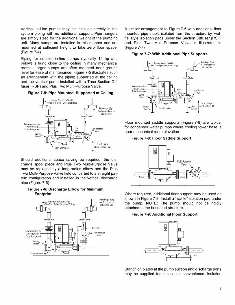
Piping for smaller in-line pumps (typically 15 hp and below) is hung close to the ceiling in many mechanical rooms. Larger pumps are often mounted near ground level for ease of maintenance. Figure 7-5 illustrates such an arrangement with the piping supported at the ceiling and the vertical pump installed with a Taco Suction Dif-fuser (RSP) and Plus Two Multi-Purpose Valve.
Figure 7-5: Pipe Mounted, Supported at Ceiling
Should additional space saving be required, the dis-charge spool piece and Plus Two Multi-Purpose Valve may be replaced by a long-radius elbow and the Plus Two Multi-Purpose Valve field converted to a straight pat-tern configuration and installed in the vertical discharge pipe (Figure 7-6).
Figure 7-6: Discharge Elbow for Minimum Footprint
A similar arrangement to Figure 7-5 with additional floor mounted pipe-stools isolated from the structure by 'waf-fle' style isolation pads under the Suction Diffuser (RSP) and Plus Two Multi-Purpose Valve is illustrated in (Figure 7-7).
Figure 7-7: With Additional Pipe Supports
Floor mounted saddle supports (Figure 7-8) are typical for condenser water pumps where cooling tower base is near mechanical room elevation.
Figure 7-8: Floor Saddle Support
Where required, additional floor support may be used as shown in Figure 7-9. Install a “waffle” isolation pad under the pump. NOTE: The pump should not be rigidly attached to the base/pad structure.
Figure 7-9: Additional Floor Support
Stanchion plates at the pump suction and discharge ports may be supplied for installation convenience. Isolation

8
pads must be used under the legs and monitored as pipe hangers are adjusted to ensure the pump flanges are not supporting the piping. Bolting to the floor or housekeep-ing pad is not recommended. If the stanchions are bolted down the bolts must be isolated from the stanchion or inertia base and flexible pipe connectors used (Figure 7-10).
Figure 7-10: With Stanchion Plates
An installation with stanchion plates for seismically active regions is illustrated in Figure 7-11. Seismically rated iso-lation pads or snubbers with bolts isolated from the stan-chion plates are installed to restrain the pump during a seismic event. Pipe hangers carry the weight of the equipment as seismic components are designed only to restrain the equipment during a seismic event.
Figure 7-11: Installation in Seismically Active Region
In systems utilizing grooved pipe, flange adapter locking devices or welded flanges at the pump should be used to prevent the possibility of pipe mounted pumps rotating in the piping (Figure 7-12).
Figure 7-12: Mounting in Grooved Pipe Systems
DO NOT support the unit by the motor eye bolts (Figure 7-13) or by any other part of the motor.
Figure 7-13: Motor Lifting Hook Supported
Connecting the pump to a permanent rigid base (Figure 7-14) is not recommended unless isolated from the piping by flexible connectors and the base isolated from the building structure on an inertia base. (Figure 7-14 is generally acceptable when using plastic piping.)
Figure 7-14: Mounted on Rigid Base without Flexible Connectors
NOTE: The pump should not be rigidly attached to the base/pad structure unless flexible couplings are used.

9
8 ELECTRICAL CONNECTIONS
8.1 Exploded ViewsFigure 8-1: Exploded View A Size
1 LCP 10 Motor output terminals 96 (U), 97 (V), 98 (W)2 RS-485 serial bus connector (+68, -69) 11 Relay 1 (01, 02, 03)3 Analog I/O connector 12 Relay 2 (04, 05, 06)4 LCP input plug 13 Brake (-81, +82) and load sharing (-88, +89) terminals5 Analog switches (A53), (A54) 14 Line power input terminals 91 (L1), 92 (L2), 93 (L3)6 Cable strain relief / PE ground 15 USB connector7 Decoupling plate 16 Serial bus terminal switch8 Grounding clamp (PE) 17 Digital I/O and 24 V power supply9 Shielded cable grounding clamp and strain relief 18 Control cable coverplate
10
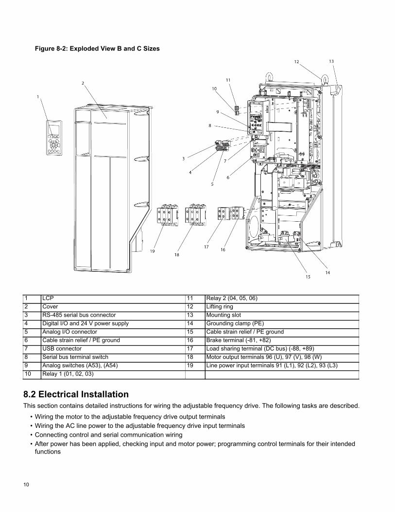
Figure 8-2: Exploded View B and C Sizes
8.2 Electrical InstallationThis section contains detailed instructions for wiring the adjustable frequency drive. The following tasks are described.
• Wiring the motor to the adjustable frequency drive output terminals• Wiring the AC line power to the adjustable frequency drive input terminals• Connecting control and serial communication wiring• After power has been applied, checking input and motor power; programming control terminals for their intended
functions
1 LCP 11 Relay 2 (04, 05, 06)2 Cover 12 Lifting ring3 RS-485 serial bus connector 13 Mounting slot4 Digital I/O and 24 V power supply 14 Grounding clamp (PE)5 Analog I/O connector 15 Cable strain relief / PE ground6 Cable strain relief / PE ground 16 Brake terminal (-81, +82)7 USB connector 17 Load sharing terminal (DC bus) (-88, +89)8 Serial bus terminal switch 18 Motor output terminals 96 (U), 97 (V), 98 (W)9 Analog switches (A53), (A54) 19 Line power input terminals 91 (L1), 92 (L2), 93 (L3)10 Relay 1 (01, 02, 03)

11
Figure 8-3 shows a basic electrical connection.
Figure 8-3: Basic Wiring Schematic Drawing
DANGER: EQUIPMENT HAZARD! Rotating shafts and electrical equipment can be hazardous. All electri-cal work must conform to national and local electrical codes. It is strongly recommended that installation, start-up, and maintenance be performed only by trained and qualified personnel. Failure to follow these guidelines could result in death or serious injury.
CAUTION: WIRING ISOLATION! Run input power, motor wiring and control wiring in three separate metallic conduits or use separated shielded cable for high frequency noise isolation. Failure to isolate power, motor and control wiring could result in less than optimum adjustable frequency drive and associ-ated equipment performance.
12
For your safety, comply with the following require-ments:
• Electronic controls equipment is connected to haz-ardous AC line voltage. Extreme care should betaken to protect against electrical hazards whenapplying power to the unit.
• Run motor cables from multiple adjustable frequencydrives separately. Induced voltage from output motorcables run together can charge equipment capacitorseven with the equipment turned off and locked out.
8.2.1 Overload and Equipment Protection• An electronically activated function within the adjust-
able frequency drive provides overload protection forthe motor. The overload calculates the level ofincrease to activate timing for the trip (controller out-put stop) function. The higher the current draw, thequicker the trip response. The overload providesClass 20 motor protection. See “14 Warnings andAlarms” on page 61 for details on the trip function.
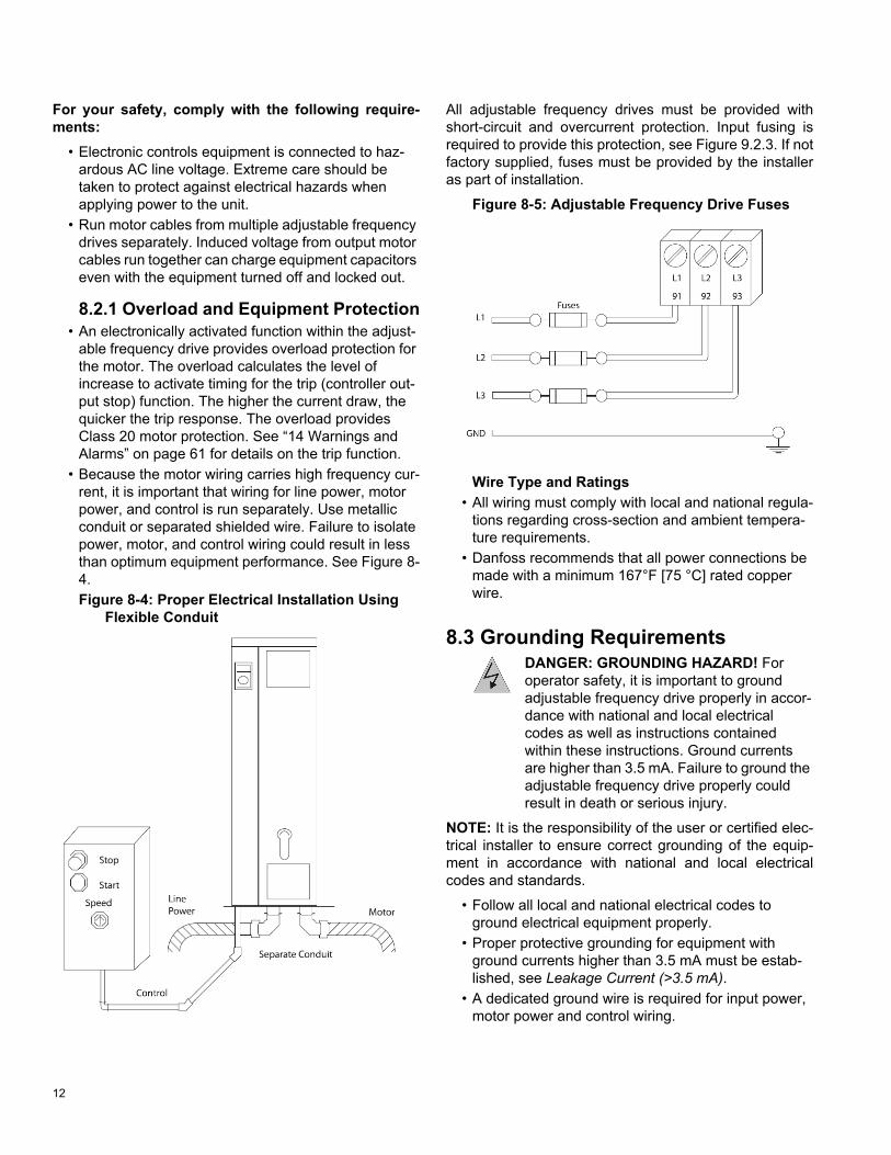
• Because the motor wiring carries high frequency cur-rent, it is important that wiring for line power, motorpower, and control is run separately. Use metallicconduit or separated shielded wire. Failure to isolatepower, motor, and control wiring could result in lessthan optimum equipment performance. See Figure 8-4.Figure 8-4: Proper Electrical Installation Using
Flexible Conduit
All adjustable frequency drives must be provided with short-circuit and overcurrent protection. Input fusing is required to provide this protection, see Figure 9.2.3. If not factory supplied, fuses must be provided by the installer as part of installation.
Figure 8-5: Adjustable Frequency Drive Fuses
Wire Type and Ratings• All wiring must comply with local and national regula-
tions regarding cross-section and ambient tempera-ture requirements.
• Danfoss recommends that all power connections bemade with a minimum 167°F [75 °C] rated copperwire.
8.3 Grounding RequirementsDANGER: GROUNDING HAZARD! For operator safety, it is important to ground adjustable frequency drive properly in accor-dance with national and local electrical codes as well as instructions contained within these instructions. Ground currents are higher than 3.5 mA. Failure to ground the adjustable frequency drive properly could result in death or serious injury.
NOTE: It is the responsibility of the user or certified elec-trical installer to ensure correct grounding of the equip-ment in accordance with national and local electrical codes and standards.
• Follow all local and national electrical codes toground electrical equipment properly.
• Proper protective grounding for equipment withground currents higher than 3.5 mA must be estab-lished, see Leakage Current (>3.5 mA).
• A dedicated ground wire is required for input power,motor power and control wiring.
13
• Use the clamps provided with on the equipment forproper ground connections.
• Do not ground one adjustable frequency drive toanother in a “daisy chain” fashion.
• Keep the ground wire connections as short as possi-ble.
• Use of high-strand wire to reduce electrical noise isrecommended.
• Follow the motor manufacturer wiring requirements.
8.3.1 Leakage Current (>3.5 mA)Follow national and local codes regarding protective grounding of equipment with a leakage current > 3.5 mA. Adjustable frequency drive technology implies high fre-quency switching at high power. This will generate a leak-age current in the ground connection. A fault current in the adjustable frequency drive at the output power termi-nals might contain a DC component which can charge the filter capacitors and cause a transient ground current. The ground leakage current depends on various system con"gurations including RFI filtering, shielded motor cables, and adjustable frequency drive power.EN/IEC61800-5-1 (Power Drive System Product Stan-dard)
requires special care if the leakage current exceeds 3.5mA.
Grounding must be reinforced in one of the following ways:
• Ground wire of at least 0.0155 in2 [10mm2]• Two separate ground wires both complying with the
dimensioning rulesSee EN/IEC61800-5-1 and EN50178 for further informa-tion.
8.3.2 Using RCDsWhere residual current devices (RCDs), also known as ground leakage circuit breakers (ELCBs), are used, com-ply with the following:
• Use RCDs of type B only which are capable ofdetecting AC and DC currents
• Use RCDs with an inrush delay to prevent faults dueto transient ground currents
• Dimension RCDs according to the system configura-tion and environmental considerations
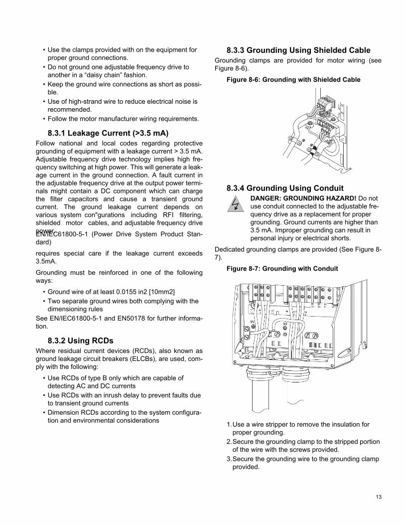
8.3.3 Grounding Using Shielded CableGrounding clamps are provided for motor wiring (see Figure 8-6).
Figure 8-6: Grounding with Shielded Cable
8.3.4 Grounding Using ConduitDANGER: GROUNDING HAZARD! Do not use conduit connected to the adjustable fre-quency drive as a replacement for proper grounding. Ground currents are higher than 3.5 mA. Improper grounding can result in personal injury or electrical shorts.
Dedicated grounding clamps are provided (See Figure 8-7).
Figure 8-7: Grounding with Conduit
1.Use a wire stripper to remove the insulation forproper grounding.
2.Secure the grounding clamp to the stripped portionof the wire with the screws provided.
3.Secure the grounding wire to the grounding clampprovided.

14
8.3.5 Motor ConnectionDANGER: INDUCED VOLTAGE! Run out-put motor cables from multiple adjustable frequency drives separately. Induced voltage from output motor cables run together can charge equipment capacitors even with the equipment turned off and locked out. Failure to run output motor cables separately could result in death or serious injury.
• For maximum wire sizes, see “17.1 Power-depen-dent Specifications” on page 75.
• Comply with local and national electrical codes forcable sizes.
• Motor wiring knockouts or access panels are pro-vided at the base of IP21 and higher (NEMA1/12)units
• Do not install power factor correction capacitorsbetween the adjustable frequency drive and themotor
• Do not wire a starting or pole-changing devicebetween the adjustable frequency drive and themotor.
• Connect the 3-phase motor wiring to terminals 96(U), 97 (V), and 98 (W).
• Ground the cable in accordance with groundinginstructions provided.
• Follow the motor manufacturer wiring requirementsThe three following figures represent line power input, motor, and grounding for basic adjustable frequency drives. Actual configurations vary with unit types and optional equipment.
Figure 8-8: Motor, Line Power and Ground Wiring for A-Frame Sizes
Figure 8-9: Motor, Line Power and Ground Wiring for B-Frame Sizes and Above Using Shielded Cable
Figure 8-10: Motor, Line Power and Ground Wiring B-Frame Sizes and Above Using Shielded Cable or Conduit
8.3.6 AC Line Power ConnectionSize wiring based upon the input current of the adjustable frequency drive.
• Comply with local and national electrical codes forcable sizes.
• Connect 3-phase AC input power wiring to terminalsL1, L2, and L3 (see Figure 8-11).

15
• Depending on the configuration of the equipment,input power will be connected to the line power inputterminals or the input disconnect.Figure 8-11: Connecting to AC Line Power
• Ground the cable in accordance with groundinginstructions provided in “8.3 Grounding Require-ments” on page 12.
• All adjustable frequency drives may be used with anisolated input source as well as with ground refer-ence power lines. When supplied from an isolatedline power source (IT line power or floating delta) orTT/TN-S line power with a grounded leg (groundeddelta), set 14-50 RFI 1 to OFF. When off, the internalRFI filter capacitors between the chassis and theintermediate circuit are isolated to avoid damage tothe intermediate circuit and to reduce ground capac-ity currents in accordance with IEC 61800-3.
8.3.7 Control WiringIsolate control wiring from high power components in the adjustable frequency drive.
If the adjustable frequency drive is connected to a therm-istor, for PELV isolation, optional thermistor control wiring must be reinforced/ double insulated. A 24 VDC supply voltage is recommended.
AccessRemove access coverplate with a screwdriver. See “Fig-ure 8-12: Control Wiring Access for A2, A3, B3, B4, C3 and C4 Enclosures” on page 15.
Or remove front cover by loosening attaching screws. See “Figure 8-13: Control Wiring Access for A4, A5, B1, B2, C1 and C2 Enclosures” on page 15.
Figure 8-12: Control Wiring Access for A2, A3, B3, B4, C3 and C4 Enclosures
Figure 8-13: Control Wiring Access for A4, A5, B1, B2, C1 and C2 Enclosures
Please see the table below before tightening the covers.
Table 1: Tightening Torques for Covers (Nm)
Frame IP20 IP21 IP55 IP66A4/A5 - - 2 2B1 - * 2.2 2.2B2 - * 2.2 2.2C1 - * 2.2 2.2C2 - * 2.2 2.2* No screws to tighten- Does not exist

16
Control Terminal TypesFigure 8-14 shows the removable adjustable frequency drive connectors.
Figure 8-14: Control Terminal Locations
• Connector 1 provides four programmable digitalinputs terminals, two additional digital terminals pro-grammable as either input or output, a 24V DC termi-nal supply voltage, and a common for optionalcustomer supplied 24V DC voltage.
• Connector 2 terminals (+)68 and (-)69 are for an RS-485 serial communications connection.
• Connector 3 provides two analog inputs, one analogoutput, 10V DC supply voltage, and commons for theinputs and output.
• Connector 4 is a USB port available for use with theMCT-10 Set-up Software.
• Also provided are two Form C relay outputs that arein various locations depending upon the adjustablefrequency drive configuration and size.Wiring to Control Terminals
Control terminal connectors can be unplugged from the adjustable frequency drive for ease of installation, as shown in Figure 8-15.
Figure 8-15: Unplugging Control Terminals
1.Open the contact by inserting a small screwdriverinto the slot above or below the contact, as shownin Figure 8-16.
2.Insert the bared control wire into the contact.3.Remove the screwdriver to fasten the control wire
into the contact.4.Ensure the contact is firmly established and not
loose. Loose control wiring can be the source ofequipment faults or less than optimal operation.
Figure 8-16: Connecting Control Wiring
Using Shielded Control CablesCorrect Shielding
The preferred method in most cases is to secure control and serial communication cables with shielding clamps provided at both ends to ensure best possible high fre-quency cable contact.
17
50/60 Hz ground loops
With very long control cables, ground loops may occur. To eliminate ground loops, connect one end of the shield-toground with a 100 nF capacitor (keeping leads short).
Avoid EMC noise on serial communication
To eliminate low-frequency noise between adjustable fre-quency drives, connect one end of the shield to terminal 61. This terminal is connected to ground via an internalRC link. Use twisted-pair cables to reduce interferencebetween conductors.
Control Terminal FunctionsAdjustable frequency drive functions are commanded by receiving control input signals.
• Each terminal must be programmed for the function itwill be supporting in the parameters associated withthat terminal.
• It is important to confirm that the control terminal isprogrammed for the correct function. See “9 UserInterface” on page 28for details on accessing param-eters..
• The default terminal programming is intended to initi-ate adjustable frequency drive functioning in a typicaloperational mode.Jumper Terminals 12 and 27
A jumper wire may be required between terminal 12 (or 13) and terminal 27 for the adjustable frequency drive tooperate when using factory default programming values.
• Digital input terminal 27 is designed to receive an24VDC external interlock command. In many appli-cations, the user wires an external interlock device toterminal 27.
• When no interlock device is used, wire a jumperbetween control terminal 12 (recommended) or 13 toterminal 27. This provides an internal 24 V signal onterminal 27.
• No signal present prevents the unit from operating.• When the status line at the bottom of the LCP reads
“AUTO REMOTE COASTING” or “Alarm 60 ExternalInterlock” is displayed, this indicates that the unit isready to operate but is missing an input signal on ter-minal 27.
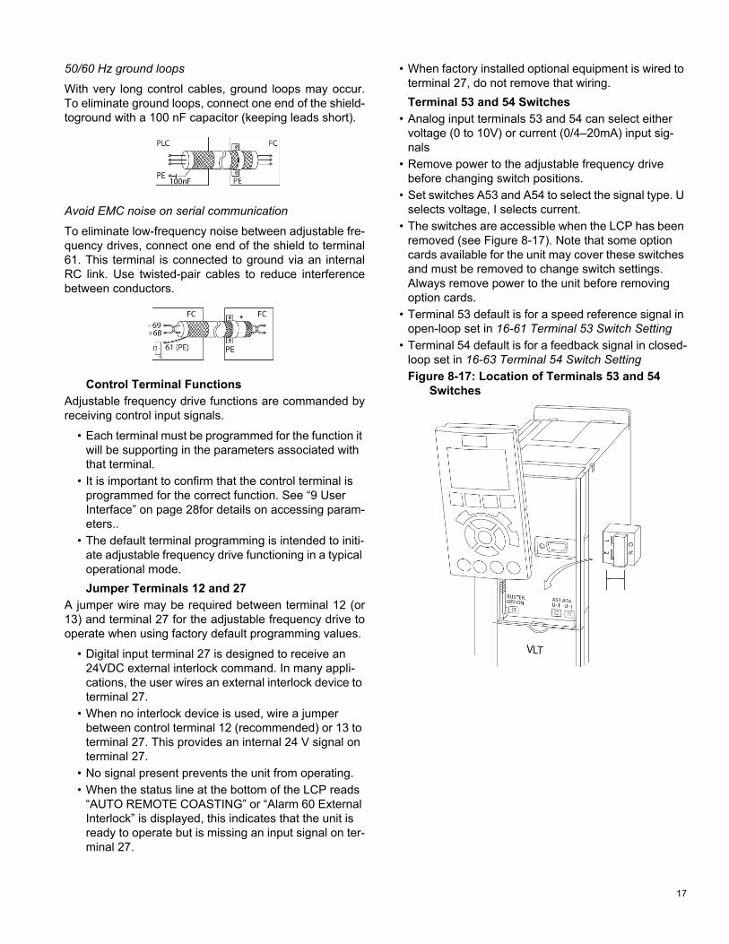
• When factory installed optional equipment is wired toterminal 27, do not remove that wiring.Terminal 53 and 54 Switches
• Analog input terminals 53 and 54 can select eithervoltage (0 to 10V) or current (0/4–20mA) input sig-nals
• Remove power to the adjustable frequency drivebefore changing switch positions.
• Set switches A53 and A54 to select the signal type. Uselects voltage, I selects current.
• The switches are accessible when the LCP has beenremoved (see Figure 8-17). Note that some optioncards available for the unit may cover these switchesand must be removed to change switch settings.Always remove power to the unit before removingoption cards.
• Terminal 53 default is for a speed reference signal inopen-loop set in 16-61 Terminal 53 Switch Setting
• Terminal 54 default is for a feedback signal in closed-loop set in 16-63 Terminal 54 Switch SettingFigure 8-17: Location of Terminals 53 and 54
Switches

18
8.4 Typical Terminal Wiring ConfigurationsThe unit connection blocks are shown in “Figure 8-14: Control Terminal Locations” on page 16.
Table 2: Control Terminal Information
Terminal number Parameter Default setting Description
Relay Outputs 01, 02, 03 5-40 Relay 1 [160] No Alarm Form C Relay Output. Used for AC or DC voltages and either resistive or inductive loads. see the following section on relay wiring for contact current and voltage ratings.
04, 05, 06 5-40 Relay 2 [5] RunningConnector 1 12, 13 - +24 V DC 24 V DC supply voltage. Maximum output current is 200 mA
total for all 24 V loads. Intended for digital inputs, external transducers.
18 5-10 [8] Start Start/Stop digital input signal for the drive. Connect input to 24 V to start. Open the input to stop the drive.
19 5-11 [0] No Operation Digital input (not used)27 5-12 [0] No Operation Digital input (not used)29 5-13 [0] No Operation Digital input (not used)32 5-14 [0] No Operation Digital input (not used)33 5-15 [0] No Operation Digital input (not used)20 - Common Common for digital inputs and reference for 24 V supply
Connector 2 61 - Shield Connection Integrated RC filter for cable shield. ONLY for connecting the shield when experiencing EMC problems.
68 8-3 + RS485 Interface (+)69 8-3 - RS485 Interface (-)
Connector 3 39 - AO Common Common for analog output42 6-50 4-20mA Motor
FreqAnalog output. Default setting is 4-20mA signal (500 ohms maximum) based on motor speed.
50 - +10 V DC 10 V DC analog supply voltage. 15mA max.53 6-1 [0] No Operation Analog input 53.54 6-2 [0] No Operation Analog input 54.55 - AI Common Common for analog input.

19
Figure 8-18: Control Terminal Connectors 1-4 and Relay Output Locations
Drive 1 Relay. Relay 1 is on the right in this view.
Relay 2.

20
8.4.1 Factory default set-upThis configuration makes use of the controller factory default settings for input/output. The factory default settings are configured for Set-up 1, SelfSensing system curve control without an external transducer. No parameters need to be changed to use this configuration. Set-up 3, SelfSensing constant flow control, uses the same default settings.
Set-ups can be changed by modifying the parameter 0-10 Active Set-up.
NOTE: The factory default settings require a start signal wired to DI18 (see below).
69 -
39COM
42AOUT
50+10V
53A IN
55COM
54A IN
12+24V
13+24V
18D IN
19D IN
27D IN
29D IN
32D IN
33D IN
20COM
68 +
61SHLD
Comm Port I/O Analog I/O Digital
Starting/StoppingController
[5-10] [8] Start*Start: Closed* factory default
21
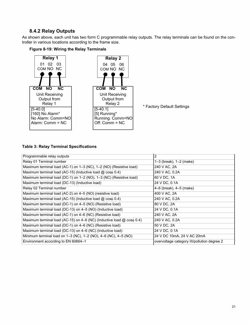
8.4.2 Relay OutputsAs shown above, each unit has two form C programmable relay outputs. The relay terminals can be found on the con-troller in various locations according to the frame size.
Figure 8-19: Wiring the Relay Terminals
01COM
Relay 102NO
03NC
04COM
Relay 205NO
06NC
COM NO NCUnit ReceivingOutput from
Relay 1[5-40.0] [160] No Alarm*No Alarm: Comm=NOAlarm: Comm = NC
COM NO NCUnit ReceivingOutput from
Relay 2[5-40.1][5] Running*Running: Comm=NOOff: Comm = NC
* Factory Default Settings
Table 3: Relay Terminal Specifications
Programmable relay outputs 2Relay 01 Terminal number 1–3 (break), 1–2 (make) Maximum terminal load (AC-1) on 1–3 (NC), 1–2 (NO) (Resistive load) 240 V AC, 2AMaximum terminal load (AC-15) (Inductive load @ cos 0.4) 240 V AC, 0.2AMaximum terminal load (DC-1) on 1–2 (NO), 1–3 (NC) (Resistive load) 60 V DC, 1AMaximum terminal load (DC-13) (Inductive load) 24 V DC, 0.1ARelay 02 Terminal number 4–6 (break), 4–5 (make) Maximum terminal load (AC-2) on 4–5 (NO) (resistive load) 400 V AC, 2AMaximum terminal load (AC-15) (Inductive load @ cos 0.4) 240 V AC, 0.2AMaximum terminal load (DC-1) on 4–5 (NO) (Resistive load) 80 V DC, 2AMaximum terminal load (DC-13) on 4–5 (NO) (Inductive load) 24 V DC, 0.1AMaximum terminal load (AC-1) on 4–6 (NC) (Resistive load) 240 V AC, 2AMaximum terminal load (AC-15) on 4–6 (NC) (Inductive load @ cos 0.4) 240 V AC, 0.2AMaximum terminal load (DC-1) on 4–6 (NC) (Resistive load) 50 V DC, 2AMaximum terminal load (DC-13) on 4–6 (NC) (Inductive load) 24 V DC, 0.1AMinimum terminal load on 1–3 (NC), 1–2 (NO), 4–6 (NC), 4–5 (NO) 24 V DC 10mA, 24 V AC 20mAEnvironment according to EN 60664–1 overvoltage category III/pollution degree 2
22
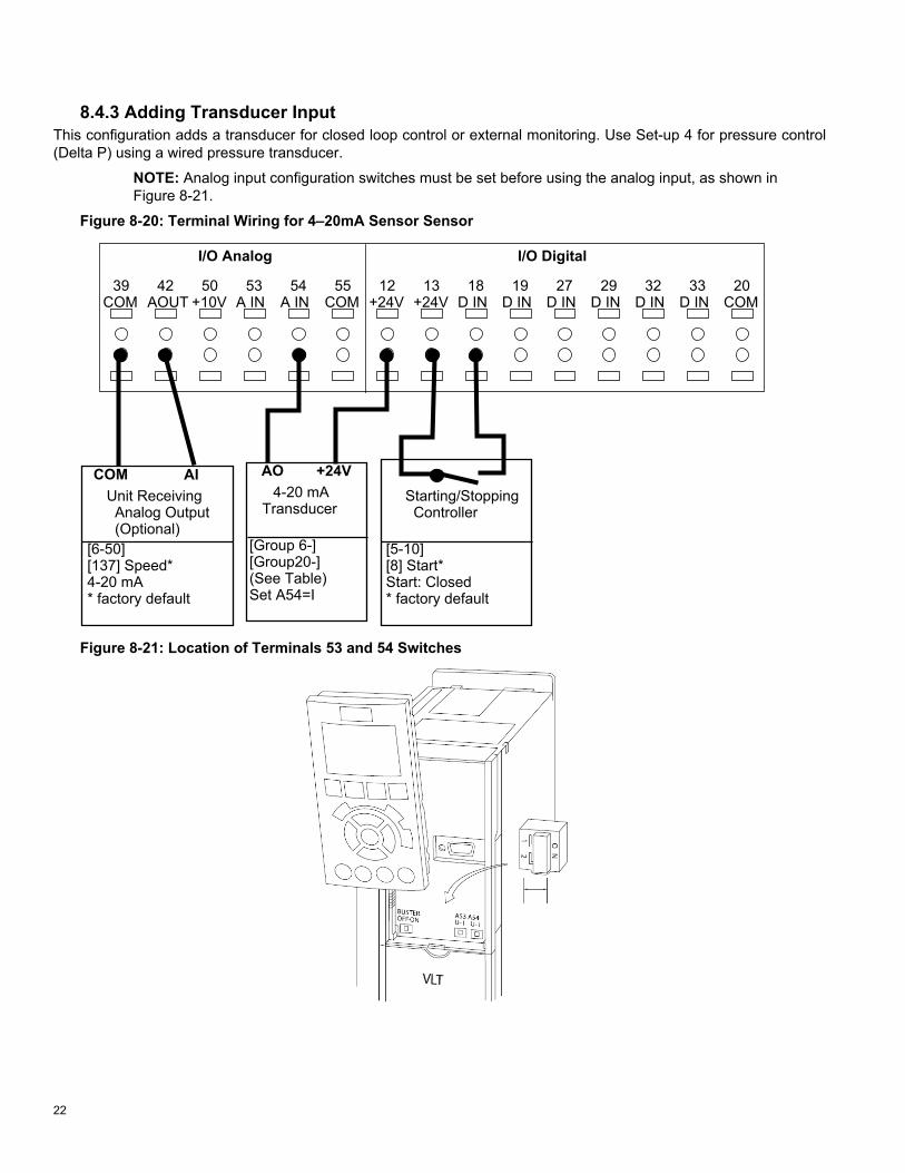
8.4.3 Adding Transducer InputThis configuration adds a transducer for closed loop control or external monitoring. Use Set-up 4 for pressure control (Delta P) using a wired pressure transducer.
NOTE: Analog input configuration switches must be set before using the analog input, as shown in Figure 8-21.
Figure 8-20: Terminal Wiring for 4–20mA Sensor Sensor
39COM
42AOUT
50+10V
53A IN
55COM
54A IN
12+24V
13+24V
18D IN
19D IN
27D IN
29D IN
32D IN
33D IN
20COM
I/O Analog I/O Digital
COM AIUnit ReceivingAnalog Output
[6-50] [137] Speed*4-20 mA* factory default
Starting/StoppingController
[5-10] [8] Start*Start: Closed* factory default
AO +24V4-20 mA
Transducer
[Group 6-] [Group20-] (See Table)Set A54=I
(Optional)
Figure 8-21: Location of Terminals 53 and 54 Switches

23
The following wiring scheme is used with Set-up 4 as shown in “10.1 SelfSensing Description” on page 34.
Figure 8-22: Terminal Wiring for 0–10V Sensor
39COM
42AOUT
50+10V
53A IN
55COM
54A IN
12+24V
13+24V
18D IN
19D IN
27D IN
29D IN
32D IN
33D IN
20COM
I/O Analog I/O Digital
COM AIUnit ReceivingAnalog Output
[6-50] [137] Speed*4-20 mA* factory default
Starting/StoppingController
[5-10] [8] Start*Start: Closed* factory default
AO +24V0-10V
Transducer
[Group 6-] [Group20-] (See Table)Set A54=U
(Optional)
To configure the controller for closed loop control based on the input from an external transducer, use the following parameters:
Table 4: Settings for a Wired Sensor for Input
* To use AI 53, set parameters 6–14, 6–15, 6–17 and set 20–00 to “Analog Input 53.”
To set up the controller with a transducer that is intended for external monitoring, as opposed to feedback to the con-troller, set the following parameters:
Parameter number Description Set to
0–10 Active Set-up For wired pressure transducer, choose Set-up 4. 6-24* Terminal 54 Low Ref./Feedb.
Value Minimum transducer input value. For example, for a 0–100 PSI transducer, set to 0. For live 0 function set feedback to 1V or 10 PSI. Note: Live 0 does not work ifminimum is set to 0.
6-25* Terminal 54 High Ref./Feedb. Value
Maximum transducer input value. For example, for a 0–100 PSI transducer, set to 100.
6-27* Terminal 54 Live Zero Enabled20-00 Feedback 1 Source Analog Input 54*20-12 Reference/Feedback Set as appropriate for application. For example, set to PSI when using a pressure
transducer. The default value for this setting is PSI.20–13 Minimum Reference/Feed-
back Minimum transducer input value. For example, for a 0–100 PSI transducer, set to 0 PSI.
20–14 Maximum Reference/Feed-back
Maximum transducer input value. For example, for a 100 PSI transducer, set to 100 PSI.

24
Table 5: Settings for a Wired Sensor for External Monitoring
* To use AI 53, set parameters 6–14, 6–15, 6–17 and set 20-00 to “Analog Input 53.”
Parameter number Description Set to
0-24 Display Line 3 Large Ext. 1 Feedback [Unit]21-14 Ext. 1 Feedback Source Analog Input 54*21–10 Ext. 1 Ref./Feedback Unit Select as appropriate for application. For example, set to PSI when using a
pressure transducer.21–11 Ext. 1 Minimum Reference Minimum transducer input value. For example, for a 0–60 PSI transducer,
set to 0 PSI.21–12 Ext. 1 Maximum Reference Maximum transducer input value. For example, for a 60 PSI transducer,
set to 60 PSI.6–24* Terminal 54 Low Ref./Feedb. Value Minimum transducer input value. For example, for a 0–60 PSI transducer,
set to 0 PSI.6–25* Terminal 54 High Ref./Feedb. Value Maximum transducer input value. For example, for a 60 PSI transducer,
set to 60 PSI.6–27* Terminal 54 Live Zero Disabled

25
8.4.4 Speed control with external potentiometerThis configuration allows an external potentiometer to control the speed of the motor.To use this set-up, the analog input must be configured as a voltage input.
The following wiring scheme is used with Set-up 2 as shown in “10.1 SelfSensing Description” on page 34.
Figure 8-23: Terminal Wiring for Potentiometer used as External Speed Reference
39COM
42AOUT
50+10V
53A IN
55COM
54A IN
12+24V
13+24V
18D IN
19D IN
27D IN
29D IN
32D IN
33D IN
20COM
I/O Analog I/O Digital
COM AIUnit ReceivingAnalog Output
[6-50] [137] Speed*4-20 mA* factory default
Starting/StoppingController
[5-10] [8] Start*Start: Closed* factory default
+10V COM
[1-00] [0] Open Loop[3-15] [1] AI54
(See Table)Set A54=U
AI53
Speed ControlPotentiometer
Group 6-Group 20-
(Optional)
To set up the controller for speed control with an external potentiometer, set the following parameters:
* Set switch A54 = U
Parameter number Description Set to
1-00 Configuration Mode Open Loop3-15 Reference 1 Source Analog Input 546-20 Terminal 54 Low Voltage* 0 V6-21 Terminal 54 High Voltage* 10 V6-24 Terminal 54 Low Ref./Feedb. Value 06-25 Terminal 54 High Ref./Feedb. Value Maximum motor speed. For example, 2950 Hz.6-27 Terminal 54 Live Zero Disabled.20-00 Feedback 1 Source No Function

26
8.4.5 Control from external PLC/BMS through Analog InputThis set-up allows an external control source such as a PLC or BMS controller to provide: a) the process variable, b) the setpoint or c) a speed reference. The output from the external control device can be either a voltage or current sig-nal. The analog input configuration switches must be set to the correct type of output signal. The drawing below shows the connections for this configuration.
This wiring scheme is used with Set-up 2, as shown in “10.1 SelfSensing Description” on page 34.
Figure 8-24: Terminal Wiring for External Control Source
39COM
42AOUT
50+10V
53A IN
55COM
54A IN
12+24V
13+24V
18D IN
19D IN
27D IN
29D IN
32D IN
33D IN
20COM
I/O Analog I/O Digital
COM AIUnit ReceivingAnalog Output
[6-50] [137] Speed*4-20 mA* factory default
Starting/StoppingController
[5-10] [8] Start*Start: Closed* factory default
AO COMPLC or BMSControl Signal
[Group 6-] [Group20-] (See Table)Set A54=U for 0-10VSet A54=I for 4-20mA
Table 6: Parameter Configuration for Use of an External Control Signal
Parameter Number
Parameter Description
For process variable from BMS/PLC* For setpoint from BMS/ PLC** For speed reference
from BMS/PLC***1-00 Configuration Mode Closed Loop Closed Loop Open Loop3-15 Reference 1 Source No Function Analog Input 54* Analog Input 54*6-24 Terminal 54 Low Ref./
Feedb. ValueMinimum value of process vari-able. For example, for a 0-60PSI transducer, set to 0.
Minimum reference/setpoint value. For example, for a 0-60PSI DP transducer, set to 0.
Minimum motor speed. For example, 0 RPM.
6-25 Terminal 54 High Ref./Feedb. Value
Maximum value of process vari-able. For example, for a 60PSI transducer, set to 60.
Maximum reference/setpoint value. For example, for a 60PSI DP transducer, set to 60.
Maximum motor speed. For example, 2950 RPM.
6-27 Terminal 54 Live Zero Enabled Enabled Disabled20-00 Feedback 1 Source Analog Input 54 Select as appropriate for applica-
tion. This can be any selection except the setting of parameter 3-15.
No Function
20-12 Reference/Feedback Unit
Select as appropriate for appli-cation. For example, set to PSI when using pressure feedback.
Select as appropriate for applica-tion. For example, set to PSI when using pressure reference.
NA
20-14 Maximum Reference/Feedback
Maximum transducer feedback value. For example, for a 60PSI transducer, set to 60 PSI.
Maximum reference/setpoint value. For example, for a 60PSI transducer, set to 60 PSI.
NA

27
* To use AI 53, configure parameters 6-14, 6-15, 6-17 and set 20-00 to Analog Input 53
8.4.6 Control From External PLC/BMS Using Communications PortThe controller can be controlled from a BMS or PLC through the communications port. In this configuration, the BMS or PLC overrides the setpoint to control the drive. Control cables must be braided screened/shielded and the screen must be connected to the metal cabinet of the controller using two cable clamps (one at each end). The bus connections must be terminated by turning the BUS TER switch to the on position. This switch can be found under the LCP, when the LCP is detached.
This wiring scheme is used with Set-up 2, as shown in “10.1 SelfSensing Description” on page 34.
Figure 8-25: Terminal Connections for External Control via Communications Port
69 -
68 +
61SHLD
Comm Port
SHLD -
RS485Controller
[8-**] Config params
+
Table 7: Parameter settings for Modbus RTU and BACnet protocols
The parameters above show a typical scenario used for Modbus RTU or BACnet protocols. The parameters must be set as appropriate for the devices on the network. 8-32 Baud Rate and 8-33 Parity/Stop Bit should be set to match the other devices on the network. For specific communication set-up information for Modbus RTU, refer to the document number MG92B102. For specific communication set-up information for BACnet, see documents MG14C102 and MG11D202. These documents can be downloaded from www.danfoss.com.
Parameter Number Parameter Description ProtocolModbus RTU BACnet
8-02 Control Source FC Port FC Port8-30 Protocol Modbus RTU BACnet8-31 Address 1 18-32 Baud Rate 19200 96008-33 Parity/Stop bit Even Parity, 1 Stop bit No Parity, 1 Stop bit8-34 Estimated cycle time 0 ms 0 ms8-35 Minimum Response Delay 10 ms 10 ms8-36 Maximum Response Delay 5000 ms 5000 ms8-37 Maximum Inter-Char Delay 0.86 ms 25 ms

28
9 USER INTERFACE
9.1 Local Control PanelThe local control panel (LCP) is the combined display and keypad on the front of the unit. The LCP is the user interface to the adjustable frequency drive.
The LCP has several user functions.
• Start, stop, and control speed when in local control• Display operational data, status, warnings and cau-
tions• Programming adjustable frequency drive functions• Manually reset the adjustable frequency drive after a
fault when auto-reset is inactiveLCP Layout
The LCP is divided into four functional groups (see Figure 9-1).
Figure 9-1: LCP
A
B
C
D
a.Display area
b.Display menu keys for changing the display toshow status options, programming, or error mes-sage history.
c.Navigation keys for programming functions, mov-ing the display cursor, and speed control in localoperation. Also included are the status indica-tors.
d.Operational mode keys and reset.Setting LCP Display Values
The display area is activated when the adjustable fre-quency drive receives power from AC line voltage, a DC bus terminal, or an external 24V supply.
The information displayed on the LCP can be customized for user application.
• Each display readout has a parameter associatedwith it.
• Options are selected in the quick menu Q3-13 Dis-play Settings.
• Display 2 has an alternate larger display option.• The adjustable frequency drive status at the bottom
line of the display is generated automatically and isnot selectable.
Figure 9-2: Status Display
1.3
1.2
2
1.1
Display Menu KeysMenu keys are used for menu access for parameter set-up, toggling through status display modes during normal operation, and viewing fault log data.
Display Parameter number Default setting
1.1 0-20 Head1.2 0-21 Motor Horsepower1.3 0-22 Motor Hz2 0-23 GPM
29
Navigation KeysNavigation keys are used for programming functions and moving the display cursor. The navigation keys also pro-vide speed control in local (hand) operation. Three adjustable frequency drive status indicators are also located in this area.
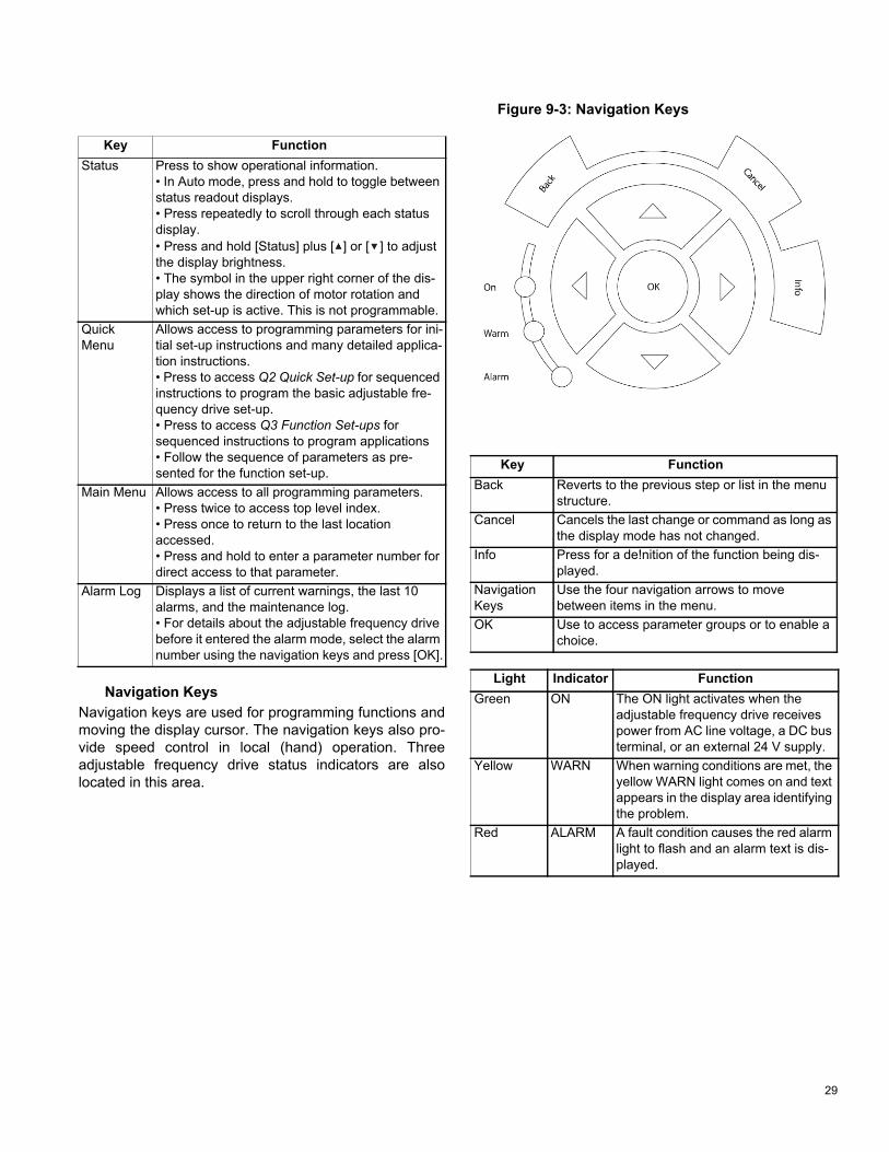
Figure 9-3: Navigation Keys
Key FunctionStatus Press to show operational information.
• In Auto mode, press and hold to toggle betweenstatus readout displays.• Press repeatedly to scroll through each statusdisplay.• Press and hold [Status] plus [ ] or [ ] to adjustthe display brightness.• The symbol in the upper right corner of the dis-play shows the direction of motor rotation andwhich set-up is active. This is not programmable.
Quick Menu
Allows access to programming parameters for ini-tial set-up instructions and many detailed applica-tion instructions.• Press to access Q2 Quick Set-up for sequencedinstructions to program the basic adjustable fre-quency drive set-up.• Press to access Q3 Function Set-ups forsequenced instructions to program applications• Follow the sequence of parameters as pre-sented for the function set-up.
Main Menu Allows access to all programming parameters.• Press twice to access top level index.• Press once to return to the last locationaccessed.• Press and hold to enter a parameter number fordirect access to that parameter.
Alarm Log Displays a list of current warnings, the last 10 alarms, and the maintenance log.• For details about the adjustable frequency drivebefore it entered the alarm mode, select the alarm number using the navigation keys and press [OK].
Key FunctionBack Reverts to the previous step or list in the menu
structure.Cancel Cancels the last change or command as long as
the display mode has not changed.Info Press for a de!nition of the function being dis-
played.Navigation Keys
Use the four navigation arrows to move between items in the menu.
OK Use to access parameter groups or to enable a choice.
Light Indicator FunctionGreen ON The ON light activates when the
adjustable frequency drive receives power from AC line voltage, a DC bus terminal, or an external 24 V supply.
Yellow WARN When warning conditions are met, the yellow WARN light comes on and text appears in the display area identifying the problem.
Red ALARM A fault condition causes the red alarmlight to flash and an alarm text is dis-played.
30
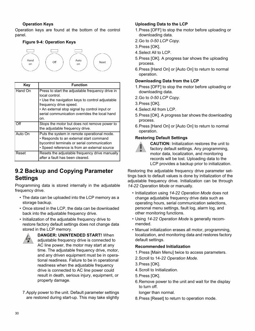
Operation KeysOperation keys are found at the bottom of the control panel.
Figure 9-4: Operation Keys
9.2 Backup and Copying Parameter SettingsProgramming data is stored internally in the adjustable frequency drive.
• The data can be uploaded into the LCP memory as astorage backup.
• Once stored in the LCP, the data can be downloadedback into the adjustable frequency drive.
• Initialization of the adjustable frequency drive torestore factory default settings does not change datastored in the LCP memory.
DANGER: UNINTENDED START! When adjustable frequency drive is connected to AC line power, the motor may start at any time. The adjustable frequency drive, motor, and any driven equipment must be in opera-tional readiness. Failure to be in operational readiness when the adjustable frequency drive is connected to AC line power could result in death, serious injury, equipment, or property damage.
Uploading Data to the LCP1.Press [OFF] to stop the motor before uploading or
downloading data.2.Go to 0-50 LCP Copy.3.Press [OK].4.Select All to LCP.5.Press [OK]. A progress bar shows the uploading
process.6.Press [Hand On] or [Auto On] to return to normal
operation.Downloading Data from the LCP1.Press [OFF] to stop the motor before uploading or
downloading data.2.Go to 0-50 LCP Copy.3.Press [OK].4.Select All from LCP.5.Press [OK]. A progress bar shows the downloading
process.6.Press [Hand On] or [Auto On] to return to normal
operation.Restoring Default Settings
CAUTION: Initialization restores the unit to factory default settings. Any programming, motor data, localization, and monitoring records will be lost. Uploading data to the LCP provides a backup prior to initialization.
Restoring the adjustable frequency drive parameter set-tings back to default values is done by initialization of the adjustable frequency drive. Initialization can be through 14-22 Operation Mode or manually.
• Initialization using 14-22 Operation Mode does notchange adjustable frequency drive data such asoperating hours, serial communication selections,personal menu settings, fault log, alarm log, andother monitoring functions.
• Using 14-22 Operation Mode is generally recom-mended.
• Manual initialization erases all motor, programming,localization, and monitoring data and restores factorydefault settings.Recommended Initialization1.Press [Main Menu] twice to access parameters.2.Scroll to 14-22 Operation Mode.3.Press [OK].4.Scroll to Initialization.5.Press [OK].6.Remove power to the unit and wait for the display
to turn off.7.Apply power to the unit. Default parameter settings
are restored during start-up. This may take slightlylonger than normal.
8.Press [Reset] to return to operation mode.
Key FunctionHand On Press to start the adjustable frequency drive in
local control.• Use the navigation keys to control adjustablefrequency drive speed.• An external stop signal by control input orserial communication overrides the local handon.
Off Stops the motor but does not remove power to the adjustable frequency drive.
Auto On Puts the system in remote operational mode.• Responds to an external start commandbycontrol terminals or serial communication• Speed reference is from an external source
Reset Resets the adjustable frequency drive manually after a fault has been cleared.

Taco® SKV
31
Manual Initialization1.Remove power to the unit and wait for the display
to turn off.2.Press and hold [Status], [Main Menu], and [OK] at
the same time and apply power to the unit.Factory default parameter settings are restored during start-up. This may take slightly longer than normal.
Manual initialization does not reset the following adjust-able frequency drive information:
• 15-00 Operating Hours• 15-03 Power-ups• 15-04 Over Temps• 15-05 Over Volts
9.3 Password Protection
9.3.1 Enable Password Protection for Main Menu1.Press [Main Menu].
2.Select 0-** Operation / Display by pressing [OK].
3.Scroll Down to parameter 0-6* Password.
4.Press [OK].
5.Scroll down to parameter 0-61 Access to Main Menu w/o Password.
6.Press [OK].
7.Change parameter 0-61 to “[2] LCP: No Access.”
8.Press [OK].
The Main Menu is now password protected. The default password is 100.
9.3.2 Disable Main Menu Password1.Follow steps 1-6 in section 9.3.1 above.2.Change parameter 0-61 to “[0] Full Access.”
3.Press [OK].
The Main Menu Password is now disabled.

32
9.3.3 Change Password for Main Menu1.Follow steps 1-4 in section 9.3.1 above.2.Scroll down to parameter 0-60 Main Menu
Password.
3.Press [OK].
4.Adjust/Edit the password using the arrow keys.
5.Press [OK].
The Main Menu password is now changed.
9.3.4 Enable Password Protection for My Personal Menu1.Press [Main Menu].
2.Select 0-** Operation / Display by pressing [OK].
3.Scroll Down to parameter 0-6* Password.
4.Press [OK].
5.Scroll down to parameter 0-66 Access to Personal Menu w/o Password.
6.Press [OK].
7.Change parameter 0-66 to “[1] LCP: Read Only.”
8.Press [OK].
The My Personal Menu is now password protected. The default password is 200.
9.3.5 Disable Password Protection for My Personal Menu1.Follow steps 1-3 in in section 9.3.4 above.2.Change parameter 0-66 to “[0] Full Access.”3.Press [OK].
The Personal Menu password protection is now disabled.

33
9.3.6 Change Password for Personal Menu1.Follow steps 1-4 in in section 9.3.4 above.2.Scroll down to parameter 0-65 Personal
Menu Password.
3.Press [OK].
4.Adjust/Edit the password using the arrow keys.
5.Press [OK].
The Personal Menu Pasword is now changed.

34
10 PUMP CONTROL SET-UPS
10.1 SelfSensing DescriptionThe Taco SelfSensing pump is a Taco pump equipped with a variable frequency drive (VFD) with SelfSensing control technology. SelfSensing control is an innovative concept in circulating pumps. Pump performance and characteristic curves are embedded in the memory of the speed controller during manufacture. This data includes power, speed, head and flow across the flow range of the pump. During operation, the power and speed of the pump are monitored, enabling the controller to establish the hydraulic performance and position in the pumps head-flow characteristic.
These measurements enable the pump to continuously identify the head and flow at any point in time, giving accurate pressure control without the need for external feedback signals. Patented software technology within the controller ensures trouble-free operation in all condi-tions.
Incorporating the pump’s hydraulic data into the control-ler and removing sensors results in true integration of all components and removes the risk of sensor failure.
10.2 Set-up Menu The controller has 4 different system set-ups:
10.2.1 Set-up Change ProcedureTo change the set-up, follow the steps below.
1.If the pump is enabled, press the [Off] button andensure the motor has stopped.
2.View the display to confirm the current set-up.
3.Press the [Quick Menus] button.
4.Press the [OK] button to enter “My PersonalMenu.”
5.Scroll down to Parameter 0-10 Active Set-up and press OK.
6.Change Active Set-up from “Set-up 1” to “Set-up 3”and press OK.
a.Parameter 0-10 Active Set-up.
b.You will know the change has happened whenyou see change to .
Set-up Description InstructionsSet-up 1 SelfSensing Variable Flow
Control Section 10.3 (Wiring: Section 8.4.2)
Set-up 2 Standby / BAS System Input Section 8.4.5
Set-up 3 SelfSensing Constant Flow Control
Section 10.4 (Wiring: Section 8.4.2)
Set-up 4 Delta P Control, 0-10V Input (Wire Pressure Transducer)
Section 8.4.3
Before
After

35
10.3 Variable Flow Control (Flow Compensation)Under Variable Flow Control (otherwise known as Flow Compensation mode), the controller is set to control the pump speed according to a ‘control curve’ between max and min flow (see Figure 10-1 below). This mode should be used for system distribution pumps. It is widely recog-nised that fitting a differential pressure sensor at the most remote load, across the supply piping and return piping encompassing the valve & coil set, is the benchmark scheme for energy efficiency.
Figure 10-1: Variable Flow Graph
ControlHead
SelfSensing pumps can replicate this control without the need for the remote sensor. As the flow required by the system is reduced, the pump automatically reduces the head developed according to the pre-set control curve. In other words, the pump follows the control curve.
It is often found that using a remote differential pressure sensor to sense the pressure across a remote load could theoretically result in loads close to the pump being under-pumped. The situation would be where the load at a loop extremity is satisfied and the control valve closes while a load close to the pump needs full flow. The proba-bility of this occuring is remote but it is possible. One answer to this is to move the sensor closer to the pump (two-thirds out in the system is a popular recommenda-tion) although physically re-positioning the sensor at a commissioning stage can be a costly exercise. With Self-Sensing pump control it is possible to replicate the mov-ing of a sensor by increasing the Control Head setting.
The design duty head and flow of the pump (provided at time of order) is shown as point ‘A’ in Figure 10-1 below.
It is not always the case that the design duty point required will fall on the maximum speed of the pump and in the majority of cases (as shown in Figure 10-1 above) it will be at a reduced speed.
The pump will be supplied with point ‘A’ set as the design duty point provided at the time of order and the minimum head at zero flow (Control Head) will be set as 40% of the design head ‘HDESIGN’ as the default.
To change the control curve from the factory settings, fol-low the startup procedures in “Appendix B: On-site Drive Mounting to Wall or Pump” on page 83.
10.4 Constant Flow ControlSelfSensing pumps can be configured to maintain a con-stant pump flow in a system. This control setting is ideal for primary systems such as boiler or chiller loops that require a constant flow.
10.4.1 For Central Plant, Constant Flow Boiler/Chiller
If this pump was ordered for a central plant constant flow boiler/chiller, you do not need to go through the balancing procedures below. Ensure the drive is already in Set-up 3 (SelfSensing Constant Flow Mode) and is therefore already self-balancing.
Figure 10-2: Constant Flow Graph
10.4.2 Settings for Constant Flow ControlTo set the pump to constant flow mode and adjust the flow rate, follow steps 1-12 in section 12.3.1.
36
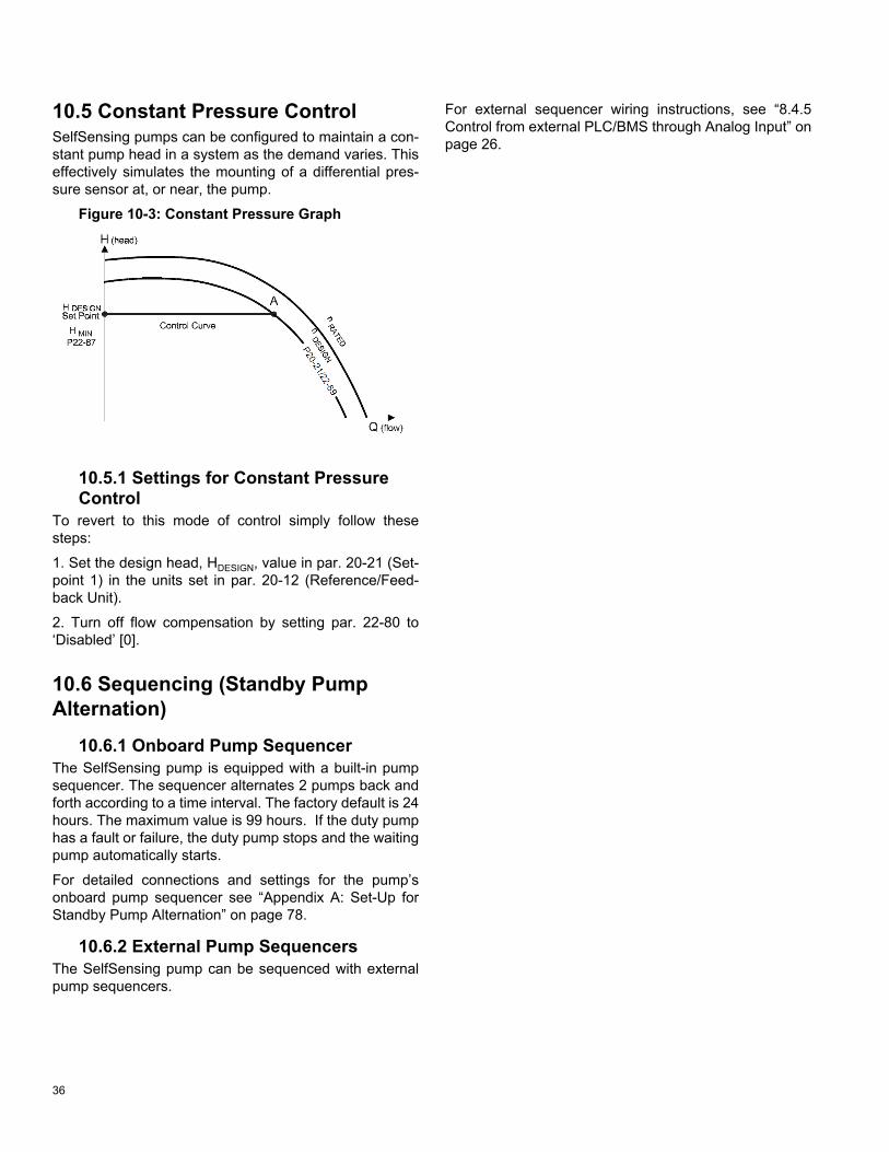
10.5 Constant Pressure ControlSelfSensing pumps can be configured to maintain a con-stant pump head in a system as the demand varies. This effectively simulates the mounting of a differential pres-sure sensor at, or near, the pump.
Figure 10-3: Constant Pressure Graph
10.5.1 Settings for Constant Pressure Control
To revert to this mode of control simply follow these steps:
1. Set the design head, HDESIGN, value in par. 20-21 (Set-point 1) in the units set in par. 20-12 (Reference/Feed-back Unit).
2. Turn off flow compensation by setting par. 22-80 to‘Disabled’ [0].
10.6 Sequencing (Standby Pump Alternation)
10.6.1 Onboard Pump SequencerThe SelfSensing pump is equipped with a built-in pump sequencer. The sequencer alternates 2 pumps back and forth according to a time interval. The factory default is 24 hours. The maximum value is 99 hours. If the duty pump has a fault or failure, the duty pump stops and the waiting pump automatically starts.
For detailed connections and settings for the pump’s onboard pump sequencer see “Appendix A: Set-Up for Standby Pump Alternation” on page 78.
10.6.2 External Pump SequencersThe SelfSensing pump can be sequenced with external pump sequencers.
For external sequencer wiring instructions, see “8.4.5 Control from external PLC/BMS through Analog Input” on page 26.

37
11 START-UP PROCEDURE
11.1 Check Points Before First StartVerify that motor is correctly wired for voltage available.
Verify that the pump has been primed. The pump should never be run dry.
NOTE: Extra effort may be required to get the air out of the seal chamber.
WARNING: Make sure power supply to pump motor is locked out before touching motor shaft.
Verify that all rotating parts turn freely.
11.2 Check Motor RotationBefore running the frequency converter, check the motor rotation. The motor will run briefly at 20Hz or the mini-mum frequency set in 4-12 Motor Speed Low Limit [Hz].
1.Check Motor rotation.a.Press [Quick Menu].b.Scroll to Q2 Quick Set-up.c.Press [OK].d.Scroll to 1-28 Motor Rotation Check.e.Press [OK].f. Scroll to Enable.g.The following text appears: “Note! Motor may run
in wrong direction.”h.Press [OK].i. Follow the on-screen instructions.
NOTE: To change the direction of rotation, remove power to the frequency converter and wait for power to discharge. Reverse the connection of any two of the three motor cables on the motor or frequency converter side of the connection.
11.3 Start PumpCAUTION: MOTOR START! Ensure that the motor, system, and any attached equipment is ready for start. It is the responsibility of the user to ensure safe operation under any con-dition. Failure to ensure that the motor, sys-tem, and any attached equipment is ready for start could result in personal injury or equipment damage.
The pump should be stopped if any of the following occur:
• No discharge.• Insufficient discharge.• Insufficient pressure.• Loss of suction.• Excessive power consumption.• Vibration.
See “16 SKS Pump Problem Analysis” on page 74 for help in troubleshooting.
2.To navigate on the keypad, use the [OK] and[ARROW] buttons shown below.
3.Ensure the drive is in Set-up 1.
4.To change to Set-up 1, press the [Quick Menus]button.
5.Press the [OK] button to enter “My Personal

38
Menu.”
6.Scroll down to Parameter 0-10 Active Set-up and press OK.
7.Change Active Set-up to “Set-up 1”.a.Parameter 0-10 Active Set-up.
b.You will know the change has happened whenyou see change to .
8.Press the [Status] button to get back to the mainscreen.
9.Close the discharge valve before starting pump.DANGER: MAKE SURE SUCTION VALVE IS OPEN!!
10.Press the [Auto on] button.
11.Once the pump has started, open the dischargevalve slowly.
CAUTION: Do not operate pump for pro-longed periods with discharge valve closed, to avoid overheating and potentially damag-ing loads.
12.After the discharge valve is fully open, let thedrive ramp up to the design flow point that wasspecified.
IMPORTANT: Allow the pump enough time to settle out at the specified design flow.
11.4 Verify FlowThe VFD is factory programmed with the Design Pres-sure Head and Design VFD Speed that were indicated at the time of order.
If this pump was ordered for a system distribution pump (quadratic system curve), it ships in Set-up 1 (it will track a system control curve like the one shown in Figure 10-1).
Follow the steps below to determine whether the pump is producing the required amount of flow.
13.Close zone valves to ensure pump speed slowsas demand is reduced. Then open the valves toensure the pump increases speed until it reachesthe desired flow.
14.If the pump is not meeting the desired flow condi-tions, as shown in the figure below, see “12 SystemBalancing” on page 39.
Figure 11-1: Over-sized Pump Example
Before
After

39
12 SYSTEM BALANCING
12.1 About SelfSensing ProBalance The pump is equipped with SelfSensing ProBalanceTM
technology. SelfSensing ProBalanceTM technology is a revolutionary system balancing method that utilizes the VFD’s SelfSensing capabilities to enable the user to accomplish easy do-it-yourself system balancing.
This guide provides a method to reset the control curve previously discussed in Section 10.2. The goal is to move the adjusted operating point at design flow so that it falls on the actual system resistance curve (Point C in Figure 12-3).
12.1.1 A Visual Guide to BalancingBelow is a graphical guide and overview of the balancing process.
Figure 12-1: Start and Assess
For information about the step above, see sections 11.3 and 11.4.
Figure 12-2: Measure System Resistance
For information about the step above, see section 12.3.1.
Figure 12-3: Reset Control Curve
For information about the step above, see section 12.3.2.
40
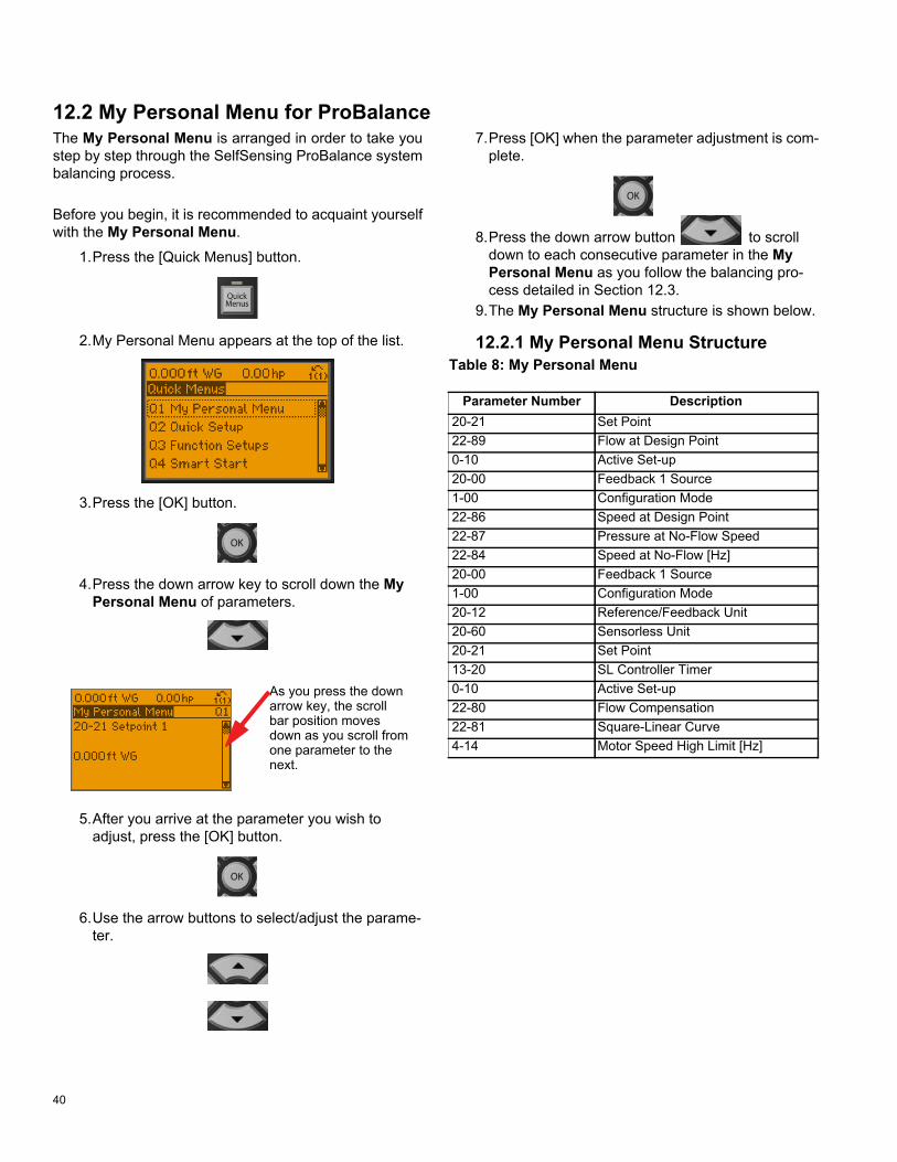
12.2 My Personal Menu for ProBalanceThe My Personal Menu is arranged in order to take you step by step through the SelfSensing ProBalance system balancing process.
Before you begin, it is recommended to acquaint yourself with the My Personal Menu.
1.Press the [Quick Menus] button.
2.My Personal Menu appears at the top of the list.
3.Press the [OK] button.
4.Press the down arrow key to scroll down the MyPersonal Menu of parameters.
5.After you arrive at the parameter you wish toadjust, press the [OK] button.
6.Use the arrow buttons to select/adjust the parame-ter.
7.Press [OK] when the parameter adjustment is com-plete.
8.Press the down arrow button to scrolldown to each consecutive parameter in the MyPersonal Menu as you follow the balancing pro-cess detailed in Section 12.3.
9.The My Personal Menu structure is shown below.
12.2.1 My Personal Menu StructureTable 8: My Personal Menu
As you press the downarrow key, the scrollbar position movesdown as you scroll fromone parameter to thenext.
Parameter Number Description20-21 Set Point22-89 Flow at Design Point0-10 Active Set-up20-00 Feedback 1 Source1-00 Configuration Mode22-86 Speed at Design Point22-87 Pressure at No-Flow Speed22-84 Speed at No-Flow [Hz]20-00 Feedback 1 Source1-00 Configuration Mode20-12 Reference/Feedback Unit20-60 Sensorless Unit20-21 Set Point13-20 SL Controller Timer0-10 Active Set-up22-80 Flow Compensation22-81 Square-Linear Curve4-14 Motor Speed High Limit [Hz]

41
12.3 Balancing Procedure
12.3.1 Measure System ResistanceFigure 12-4 shows a typical system response at startup. Point A is programmed at the factory per the specifica-tion/equipment schedule and the pump is set to stay on the control curve shown in Figure 12-1. However, pumps are typically oversized due to safety factor. Since the actual system resistance is too low for the pump to oper-ate at Point A, after it reaches its max speed (typically 60hz), the pump will 'run out' to the right on the 60hz curve to Point B.
Figure 12-4: Measure System Resistance
The following procedure shows how to measure the actual system resistance at the intended design flow. (Point C) This point is used later to reprogram the pump to operate along the adjusted control curve shown in Figure 12-3.
1.Ensure the system is filled and all valves are set to100% open.
2.To navigate on the keypad use the [OK] and[ARROW] buttons shown below.
3.Press the [Off] Button.
4.Ensure the drive is in the set-up you ordered.
5.Press the [Quick Menus] button.
6.Press the [OK] button to enter “My PersonalMenu.”
7.Scroll down to Parameter 0-10 Active Set-up and press OK.
8.Change Active Set-up from “Set-up 1” to “Set-up 3”and press OK.
a.Parameter 0-10 Active Set-up.
b.You will know the change has happened whenyou see change to .
Before
After

42
9.Scroll up to parameter 20-21 Setpoint 1 and press OK.
10.Set the system’s flow at design point (flow valuethat was specified at the time of order is alreadydisplayed) and press [OK].
a.Parameter 20-21 Setpoint 1.
11.Press the [Auto on] button.
12.Press the [Status] button to get back to the mainscreen.
a.Let the drive ramp up to the design flow pointthat was specified.
b.IMPORTANT: Allow the pump enough time tosettle out at the specified design flow.
c. IMPORTANT: Record the Hz and ft WG dis-played on the top of the LCD.
13.Press the [Off] Button.
a.Wait for the pump to come to a complete stopbefore moving to the next step.
12.3.2 Set Adjusted Operating Point at Design Flow Figure 12-5: Set Control Curve Max (Point C)
Point C
1.Press the [Quick Menus] button.
2.Press the [OK] button to enter “My PersonalMenu.”
3.Scroll down to parameter 0-10 Active Set-up and press OK.
4.Change Active Set-up from “Set-up 3” to “Set-up 1”then press OK.
a.Parameter 0-10 Active Set-up.
b.You will know the change has happened whenyou see change to .
Before
After

43
5.Scroll down to parameter 20-00 Feedback Source and press OK.
6.Change feedback from “Sensorless Pressure” to“No function” then press OK.
a.Parameter 20-00 = Feedback 1 Source.
7.Scroll down to parameter 1-00 Configuration Mode and press OK.
8.Change the Configuration Mode from “ClosedLoop” to “Open Loop” then press OK.
a.Parameter 1-00 = Configuration Mode.
9.Scroll down to to parameter 22-86 Speed at Design Point and press OK.
10.Enter the Hz you recorded in Set-up 3 (from Step12 above) and press OK.
a.Parameter 22-86 = Speed at Design Point [Hz].
11.Scroll down to parameter 20-00 Feedback 1 Source and press OK.
12.Change feedback from “No function” to “Sensor-less Pressure” and press OK.
a.Parameter 20-00 = Feedback 1 Source.
13.Scroll down to parameter 1-00 Configura-tion Mode and press OK.
Before
After
Before
After
Before
After

44
14.Change the Configuration Mode from “OpenLoop” to “Closed Loop” and press OK.
a.Parameter 1-00 = Configuration Mode.
15.Scroll down to parameter 20-12 Reference/Feedback Unit and press OK.
16.Change the Reference/Feedback Unit to ft WG(press the [Down Arrow] button to reach the settingfaster). IMPORTANT: Due to the change in param-eters, the drive will default back to metric units. It isimportant to set the units back to ft WG for properfunction. Then press OK.
a.Parameter 20-12 = Reference/Feedback Unit toft Wg.
17.Scroll down to parameter 20-60 Sensor-less Unit and press OK.
18.Change Sensorless Unit to GPM (press the [UpArrow] button to reach the setting faster). IMPOR-TANT: Due to the change in parameters, the drivewill default back to metric units. It is important to
set the units back to GPM for proper function. Then press OK.
a.Parameter 20-60 = Sensorless Unit to GPM.
19.Scroll down to parameter 20-21 Setpoint 1and press OK.
20.Enter the Pressure Head set point (ft WG) thatyou previously recorded (from Step 12). Thenpress OK.
a.Parameter 20-21 = Setpoint 1.
21.Press the [Auto on] button to start the pump.
22.Press the [Status] button to get back to the mainscreen.
23.Press the [Quick Menus] button.
Before
After
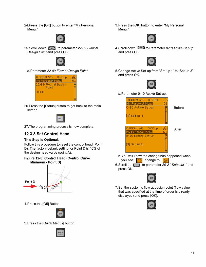
45
24.Press the [OK] button to enter “My PersonalMenu.”
25.Scroll down to parameter 22-89 Flow at Design Point and press OK.
a.Parameter 22-89 Flow at Design Point.
26.Press the [Status] button to get back to the mainscreen.
27.The programming process is now complete.
12.3.3 Set Control Head This Step is Optional. Follow this procedure to reset the control head (Point D). The factory default setting for Point D is 40% of the design head value (point A).
Figure 12-6: Control Head (Control Curve Minimum - Point D)
Point D
1.Press the [Off] Button.
2.Press the [Quick Menus] button.
3.Press the [OK] button to enter “My PersonalMenu.”
4.Scroll down to Parameter 0-10 Active Set-up and press OK.
5.Change Active Set-up from “Set-up 1” to “Set-up 3”and press OK.
a.Parameter 0-10 Active Set-up.
b.You will know the change has happened whenyou see change to .
6.Scroll up to parameter 20-21 Setpoint 1 and press OK.
7.Set the system’s flow at design point (flow valuethat was specified at the time of order is alreadydisplayed) and press [OK].
Before
After
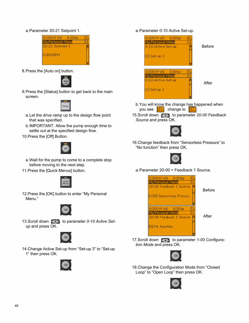
46
a.Parameter 20-21 Setpoint 1.
8.Press the [Auto on] button.
9.Press the [Status] button to get back to the mainscreen.
a.Let the drive ramp up to the design flow pointthat was specified.
b.IMPORTANT: Allow the pump enough time tosettle out at the specified design flow.
10.Press the [Off] Button.
a.Wait for the pump to come to a complete stopbefore moving to the next step.
11.Press the [Quick Menus] button.
12.Press the [OK] button to enter “My PersonalMenu.”
13.Scroll down to parameter 0-10 Active Set-up and press OK.
14.Change Active Set-up from “Set-up 3” to “Set-up1” then press OK.
a.Parameter 0-10 Active Set-up.
b.You will know the change has happened whenyou see change to .
15.Scroll down to parameter 20-00 Feedback Source and press OK.
16.Change feedback from “Sensorless Pressure” to“No function” then press OK.
a.Parameter 20-00 = Feedback 1 Source.
17.Scroll down to parameter 1-00 Configura-tion Mode and press OK.
18.Change the Configuration Mode from “ClosedLoop” to “Open Loop” then press OK.
Before
After
Before
After

47
a.Parameter 1-00 = Configuration Mode.
19.Scroll down to parameter 22-87 Pressure at No-Flow Speed and press OK.
20.Set the desired Pressure at No-Flow in ft WG(Control Head) then press OK.
a.Parameter 22-87 = Pressure at No-Flow Speed.
21.Scroll down to parameter 22-84 Speed at No-Flow and press OK.
22.Set the VFD Speed required to produce thedesired static pressure head when your system isat No-Flow conditions. The factory default is 40%of Design Pressure Head. Consult the online refer-ence look up table for your specific pump model todetermine the relationship between static headpressure and VFD Speed requirements. Thenpress OK.
a.Parameter 22-84 = Speed at No-Flow.
23.Scroll down to parameter 20-00 Feedback 1 Source and press OK.
24.Change feedback from “No function” to “Sensor-less Pressure” and press OK.
a.Parameter 20-00 = Feedback 1 Source.
25.Scroll down to parameter 1-00 Configura-tion Mode and press OK.
26.Change the Configuration Mode from “OpenLoop” to “Closed Loop” and press OK.
Before
After
Before
After

48
a.Parameter 1-00 = Configuration Mode.
27.Scroll down to parameter 20-12 Reference/Feedback Unit and press OK.
28.Change the Reference/Feedback Unit to ft WG(press the [Down Arrow] button to reach the settingfaster). IMPORTANT: Due to the change in param-eters, the drive will default back to metric units. It isimportant to set the units back to ft WG for properfunction. Then press OK.
a.Parameter 20-12 = Reference/Feedback Unit toft Wg.
29.Scroll down to parameter 20-60 Sensor-less Unit and press OK.
30.Change Sensorless Unit to GPM (press the [UpArrow] button to reach the setting faster). IMPOR-TANT: Due to the change in parameters, the drivewill default back to metric units. It is important toset the units back to GPM for proper function. Thenpress OK.
a.Parameter 20-60 = Sensorless Unit to GPM.
31.Press the [Auto on] button to start the pump.
32.Press the [Status] button to get back to the mainscreen.
33.The programming process is now complete andyou can run the drive.
Before
After

49
12.3.4 Flow Fine TuningAfter balancing is complete, if the flow at Point C requires fine tuning, simply increase or decrease Parameter 20-21 Setpoint 1 until desired flow is achieved. Follow this pro-cedure to adjust the setpoint.
1.Press the [Quick Menus] button.
2.Press the [OK] button to enter “My PersonalMenu.”
3.Scroll down to parameter 20-21 Setpoint 1 and press OK.
4.Enter the Pressure Head set point (ft WG) that willachieve the desired flow. Then press OK.
a.Parameter 20-21 = Setpoint 1.
5.Press the [Auto on] button to start the pump.
6.Press the [Status] button to get back to the mainscreen.
12.4 Additional SettingsOther settings that are set to enable the pump to operate on a control curve are:
• Par. 22-80 (Flow Compensation), which should beset to ‘Enabled’ [1]
• Par 22-81 (Square-linear Curve Approximation),which should be set to ‘100%’.Figure 12-7: Curve Approximation Settings
The effect of adjusting par. 22-81 is shown in Figure 12-7 above. A setting of 100% gives the ideal theoretical con-trol curve between the design head and minimum head while 0% provides a straight line linear approximation.

50
13 M
ENU
S13
.0.1
Qui
ck M
enu
Stru
ctur
e - p
age
1
Q3-
1 G
ener
al S
ettin
gs
0-24
Dis
play
Lin
e 3
Larg
e1-
00 C
onfig
urat
ion
Mod
eQ
3-31
Sin
gle
Zone
Ext
. Set
poin
t 20
-70
Clo
sed-
loop
Typ
eQ
3-10
Adv
. Mot
or S
ettin
gs
0-37
Dis
play
Tex
t 120
-12
Ref
eren
ce/F
eedb
ack
Uni
t1-
00 C
onfig
urat
ion
Mod
e20
-71
PID
Per
form
ance
1-90
Mot
or T
herm
al P
rote
ctio
n0-
38 D
ispl
ay T
ext 2
20-1
3 M
inim
um R
efer
ence
/Fe
edb.
20-1
2 R
efer
ence
/Fee
dbac
k U
nit
20-7
2 P
ID O
utpu
t Cha
nge
1-93
The
rmis
tor S
ourc
e0-
39 D
ispl
ay T
ext 3
20-1
4 M
axim
um R
efer
ence
/Fe
edb.
20-1
3 M
inim
um R
efer
ence
/Fe
edb.
20-7
3 M
inim
um F
eedb
ack
Leve
l
1-29
Aut
omat
ic M
otor
Ada
ptat
ion
(AM
A)
Q3-
2 O
pen-
loop
Set
tings
6-
22 T
erm
inal
54
Low
Cur
rent
20-1
4 M
axim
um R
efer
ence
/Fe
edb.
20-7
4 M
axim
um F
eedb
ack
Leve
l
14-0
1 S
witc
hing
Fre
quen
cyQ
3-20
Dig
ital R
efer
ence
6-
24 T
erm
inal
54
Low
Ref
./Fe
edb.
Val
ue6-
10 T
erm
inal
53
Low
Vol
tage
20-7
9 P
ID A
utot
unin
g
4-53
War
ning
Spe
ed H
igh
3-02
Min
imum
Ref
eren
ce6-
25 T
erm
inal
54
Hig
h R
ef./
Feed
b. V
alue
6-11
Ter
min
al 5
3 H
igh
Vol
tage
Q3-
32 M
ulti
Zone
/ A
dv
Q3-
11 A
nalo
g O
utpu
t 3-
03 M
axim
um R
efer
ence
6-26
Ter
min
al 5
4 Fi
lter T
ime
Con
stan
t6-
12 T
erm
inal
53
Low
Cur
rent
1-00
Con
figur
atio
n M
ode
6-50
Ter
min
al 4
2 O
utpu
t3-
10 P
rese
t Ref
eren
ce6-
27 T
erm
inal
54
Live
Zer
o6-
13 T
erm
inal
53
Hig
h C
urre
nt3-
15 R
efer
ence
1 S
ourc
e6-
51 T
erm
inal
42
Out
put M
inS
cale
5-13
Ter
min
al 2
9 D
igita
lIn
put
6-00
Liv
e Ze
ro T
imeo
ut T
ime
6-14
Ter
min
al 5
3 Lo
w R
ef./F
eedb
.V
alue
3-16
Ref
eren
ce 2
Sou
rce
6-52
Ter
min
al 4
2 O
utpu
t Max
Sca
le5-
14 T
erm
inal
32
Dig
ital
Inpu
t6-
01 L
ive
Zero
Tim
eout
Fun
c-tio
n6-
15 T
erm
inal
53
Hig
h R
ef./
Feed
b. V
alue
20-0
0 Fe
edba
ck 1
Sou
rce
Q3-
12 C
lock
Set
tings
5-
15 T
erm
inal
33
Dig
ital
Inpu
t20
-21
Set
poin
t 16-
22 T
erm
inal
54
Low
Cur
rent
20-0
1 Fe
edba
ck 1
Con
vers
ion
0-70
Dat
e an
d Ti
me
Q3-
21 A
nalo
g R
efer
ence
20
-81
PID
Nor
mal
/ Inv
erse
Con
trol
6-24
Ter
min
al 5
4 Lo
w R
ef./F
eedb
. V
alue
20-0
2 Fe
edba
ck 1
Sou
rce
Uni
t
0-71
Dat
e Fo
rmat
3-02
Min
imum
Ref
eren
ce20
-82
PID
Sta
rt S
peed
[RP
M]
6-25
Ter
min
al 5
4 H
igh
Ref
./Fe
edb.
Val
ue20
-03
Feed
back
2 S
ourc
e
0-72
Tim
e Fo
rmat
3-03
Max
imum
Ref
eren
ce20
-83
PID
Sta
rt S
peed
[Hz]
6-26
Ter
min
al 5
4 Fi
lter T
ime
Con
-st
ant
20-0
4 Fe
edba
ck 2
Con
vers
ion
0-74
DS
T/S
umm
ertim
e6-
10 T
erm
inal
53
Low
Vol
t-ag
e20
-93
PID
Pro
porti
onal
Gai
n6-
27 T
erm
inal
54
Live
Zer
o20
-05
Feed
back
2 S
ourc
e U
nit
0-76
DS
T/S
umm
ertim
e S
tart
6-11
Ter
min
al 5
3 H
igh
Vol
t-ag
e20
-94
PID
Inte
gral
Tim
e6-
00 L
ive
Zero
Tim
eout
Tim
e20
-06
Feed
back
3 S
ourc
e
0-77
DS
T/S
umm
ertim
e E
nd6-
12 T
erm
inal
53
Low
Cur
-re
nt20
-70
Clo
sed-
loop
Typ
e6-
01 L
ive
Zero
Tim
eout
Fun
ctio
n20
-07
Feed
back
3 C
onve
rsio
n
Q3-
13 D
ispl
ay S
ettin
gs
6-13
Ter
min
al 5
3 H
igh
Cur
-re
nt20
-71
PID
Per
form
ance
20-8
1 P
ID N
orm
al/ I
nver
se C
on-
trol
20-0
8 Fe
edba
ck 3
Sou
rce
Uni
t
0-20
Dis
play
Lin
e 1.
1 S
mal
l6-
14 T
erm
inal
53
Low
Ref
./Fe
edb.
Val
ue20
-72
PID
Out
put C
hang
e20
-82
PID
Sta
rt S
peed
[RP
M]
20-1
2 R
efer
ence
/Fee
dbac
k U
nit
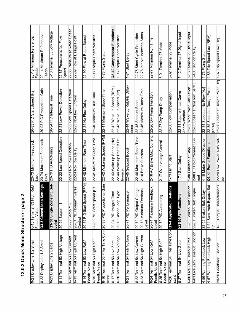
51
13.0
.2 Q
uick
Men
u St
ruct
ure
- pag
e 2
0-21
Dis
play
Lin
e 1.
2 S
mal
l6-
15 T
erm
inal
53
Hig
h R
ef./
Feed
b. V
alue
20-7
3 M
inim
um F
eedb
ack
Leve
l20
-83
PID
Sta
rt S
peed
[Hz]
20-1
3 M
inim
um R
efer
ence
/Fe
edb.
0-22
Dis
play
Lin
e 1.
3 S
mal
lQ
3-3
Clo
sed-
loop
Set
tings
20
-74
Max
imum
Fee
dbac
kLe
vel
20-9
3 P
ID P
ropo
rtion
al G
ain
20-1
4 M
axim
um R
efer
ence
/Fe
edb.
0-23
Dis
play
Lin
e 2
Larg
eQ
3-30
Sin
gle
Zone
Int.
Set-
poin
t 20
-79
PID
Aut
otun
ing
20-9
4 P
ID In
tegr
al T
ime
6-10
Ter
min
al 5
3 Lo
w V
olta
ge
6-11
Ter
min
al 5
3 H
igh
Vol
tage
20-2
1 S
etpo
int 1
22-2
2 Lo
w S
peed
Det
ectio
n22
-21
Low
Pow
er D
etec
tion
22-8
7 P
ress
ure
at N
o-Fl
owS
peed
6-12
Ter
min
al 5
3 Lo
w C
urre
nt20
-22
Set
poin
t 222
-23
No-
Flow
Fun
ctio
n22
-22
Low
Spe
ed D
etec
tion
22-8
8 P
ress
ure
at R
ated
Spe
ed6-
13 T
erm
inal
53
Hig
h C
urre
nt20
-81
PID
Nor
mal
/ Inv
erse
Con
trol
22-2
4 N
o-Fl
ow D
elay
22-2
3 N
o-Fl
ow F
unct
ion
22-8
9 Fl
ow a
t Des
ign
Poi
nt
6-14
Ter
min
al 5
3 Lo
w R
ef./
Feed
b. V
alue
20-8
2 P
ID S
tart
Spe
ed [R
PM
]22
-40
Min
imum
Run
Tim
e22
-24
No-
Flow
Del
ay22
-90
Flow
at R
ated
Spe
ed
6-15
Ter
min
al 5
3 H
igh
Ref
./Fe
edb.
Val
ue20
-83
PID
Sta
rt S
peed
[Hz]
22-4
1 M
inim
um S
leep
Tim
e22
-40
Min
imum
Run
Tim
e1-
03 T
orqu
e C
hara
cter
istic
s
6-16
Ter
min
al 5
3 Fi
lter T
ime
Con
-st
ant
20-9
3 P
ID P
ropo
rtion
al G
ain
22-4
2 W
ake-
up S
peed
[RP
M]
22-4
1 M
inim
um S
leep
Tim
e1-
73 F
lyin
g S
tart
6-17
Ter
min
al 5
3 Li
ve Z
ero
20-9
4 P
ID In
tegr
al T
ime
22-4
3 W
ake-
up S
peed
[Hz]
22-4
2 W
ake-
up S
peed
[RP
M]
Q3-
42 C
ompr
esso
r Fun
ctio
ns
6-20
Ter
min
al 5
4 Lo
w V
olta
ge20
-70
Clo
sed-
loop
Typ
e22
-44
Wak
e-up
Ref
./FB
Dif-
fere
nce
22-4
3 W
ake-
up S
peed
[Hz]
1-03
Tor
que
Cha
ract
eris
tics
6-21
Ter
min
al 5
4 H
igh
Vol
tage
20-7
1 P
ID P
erfo
rman
ce22
-45
Set
poin
t Boo
st22
-44
Wak
e-up
Ref
./FB
Diff
er-
ence
1-71
Sta
rt D
elay
6-22
Ter
min
al 5
4 Lo
w C
urre
nt20
-72
PID
Out
put C
hang
e22
-46
Max
imum
Boo
st T
ime
22-4
5 S
etpo
int B
oost
22-7
5 S
hort
Cyc
le P
rote
ctio
n6-
23 T
erm
inal
54
Hig
h C
urre
nt20
-73
Min
imum
Fee
dbac
kLe
vel
2-10
Bra
ke F
unct
ion
22-4
6 M
axim
um B
oost
Tim
e22
-76
Inte
rval
bet
wee
n S
tarts
6-24
Ter
min
al 5
4 Lo
w R
ef./
Feed
b. V
alue
20-7
4 M
axim
um F
eedb
ack
Leve
l2-
16 A
C B
rake
Max
. Cur
rent
22-2
6 D
ry P
ump
Func
tion
22-7
7 M
inim
um R
un T
ime
6-25
Ter
min
al 5
4 H
igh
Ref
./Fe
edb.
Val
ue20
-79
PID
Aut
otun
ing
2-17
Ove
r-vo
ltage
Con
trol
22-2
7 D
ry P
ump
Del
ay5-
01 T
erm
inal
27
Mod
e
6-26
Ter
min
al 5
4 Fi
lter T
ime
Con
-st
ant
Q3-
4 A
pplic
atio
n Se
tting
s 1-
73 F
lyin
g S
tart
22-8
0 Fl
ow C
ompe
nsat
ion
5-02
Ter
min
al 2
9 M
ode
6-27
Ter
min
al 5
4 Li
ve Z
ero
Q3-
40 F
an F
unct
ions
1-
71 S
tart
Del
ay22
-81
Squ
are-
linea
r Cur
veA
ppro
xim
atio
n5-
12 T
erm
inal
27
Dig
ital I
nput
6-00
Liv
e Ze
ro T
imeo
ut T
ime
22-6
0 B
roke
n B
elt F
unct
ion
1-80
Fun
ctio
n at
Sto
p22
-82
Wor
k P
oint
Cal
cula
tion
5-13
Ter
min
al 2
9 D
igita
l Inp
ut6-
01 L
ive
Zero
Tim
eout
Fun
ctio
n22
-61
Bro
ken
Bel
t Tor
que
2-00
DC
Hol
d/P
rehe
at C
ur-
rent
22-8
3 S
peed
at N
o-Fl
ow [R
PM
]5-
40 F
unct
ion
Rel
ay
4-56
War
ning
Fee
dbac
k Lo
w22
-62
Bro
ken
Bel
t Del
ay4-
10 M
otor
Spe
ed D
irect
ion
22-8
4 S
peed
at N
o-Fl
ow [H
z]1-
73 F
lyin
g S
tart
4-57
War
ning
Fee
dbac
k H
igh
4-64
Sem
i-Aut
o B
ypas
s S
et-
upQ
3-41
Pum
p Fu
nctio
ns
22-8
5 S
peed
at D
esig
n P
oint
[RP
M]
1-86
Trip
Spe
ed L
ow [R
PM
]
20-2
0 Fe
edba
ck F
unct
ion
1-03
Tor
que
Cha
ract
eris
tics
22-2
0 Lo
w P
ower
Aut
o S
et-
up22
-86
Spe
ed a
t Des
ign
Poi
nt [H
z]1-
87 T
rip S
peed
Low
[Hz]

52
13.0
.3 M
ain
Men
u St
ruct
ure
- pag
e 1
0-**
Ope
ratio
n / D
ispl
ay
0-37
Dis
play
Tex
t 10-
77 D
ST/
Sum
mer
time
End
1-36
Iron
Los
s R
esis
tanc
e (R
fe)
1-82
Min
Spe
ed fo
r Fun
ctio
n at
Sto
p [H
z]0-
0* B
asic
Set
tings
0-38
Dis
play
Tex
t 20-
79 C
lock
Fau
lt1-
39 M
otor
Pol
es1-
86 T
rip S
peed
Low
[RP
M]
0-01
Lan
guag
e0-
39 D
ispl
ay T
ext 3
0-81
Wor
king
Day
s1-
5* L
oad-
Inde
p. S
ettin
g1-
87 T
rip S
peed
Low
[Hz]
0-02
Mot
or S
peed
Uni
t0-
4* L
CP
Key
pad
0-82
Add
ition
al W
orki
ngD
ays
1-50
Mot
or M
agne
tizat
ion
atZe
ro
Spe
ed1-
9* M
otor
Tem
pera
ture
0-03
Reg
iona
l Set
tings
0-40
[Han
d on
] Key
on
LCP
0-83
Add
ition
al N
on-W
orki
ngD
ays
1-51
Min
Spe
ed N
orm
al M
agne
-tiz
ing
[RP
M]
1-90
Mot
or T
herm
al P
rote
ctio
n
0-04
Ope
ratin
g S
tate
at P
ower
-up
0-41
[Off]
Key
on
LCP
0-89
Dat
e an
d Ti
me
Rea
dout
1-52
Min
Spe
ed N
orm
al M
agne
-tiz
ing
[Hz]
1-91
Mot
or E
xter
nal F
an
0-05
Loc
al M
ode
Uni
t0-
42 [A
uto
on] K
ey o
n LC
P1-
** L
oad
and
Mot
or1-
58 F
lyst
art T
est P
ulse
s C
urre
nt1-
93 T
herm
isto
r Sou
rce
0-1*
Set
-up
Ope
ratio
ns0-
43 [R
eset
] Key
on
LCP
1-0*
Gen
eral
Set
tings
1-59
Fly
star
t Tes
t Pul
ses
Fre-
quen
cy2-
** B
rake
s
0-10
Act
ive
Set
-up
0-44
[Off/
Res
et] K
ey o
n LC
P1-
00 C
onfig
urat
ion
Mod
e1-
6* L
oad-
Dep
end.
Set
tg.
2-0*
DC
Bra
ke0-
11 P
rogr
amm
ing
Set
-up
0-45
[Driv
e B
ypas
s] K
ey o
nLC
P1-
03 T
orqu
e C
hara
cter
istic
s1-
60 L
ow S
peed
Loa
d C
ompe
n-sa
tion
2-00
DC
Hol
d/P
rehe
at C
urre
nt
0-12
Thi
s S
et-u
p Li
nked
to0-
5* C
opy/
Save
1-06
Clo
ckw
ise
Dire
ctio
n1-
61 H
igh
Spe
ed L
oad
Com
pen-
satio
n2-
01 D
C B
rake
Cur
rent
0-13
Rea
dout
: Lin
ked
Set
-ups
0-50
LC
P C
opy
1-2*
Mot
or D
ata
1-62
Slip
Com
pens
atio
n2-
02 D
C B
raki
ng T
ime
0-14
Rea
dout
: Pro
g. S
et-u
ps /
Cha
nnel
0-51
Set
-up
Cop
y1-
20 M
otor
Pow
er [k
W]
1-63
Slip
Com
pens
atio
n Ti
me
Con
stan
t2-
03 D
C B
rake
Cut
-in S
peed
[RP
M]
0-2*
LC
P D
ispl
ay0-
6* P
assw
ord
1-21
Mot
or P
ower
[HP
]1-
64 R
eson
ance
Dam
peni
ng2-
04 D
C B
rake
Cut
In S
peed
[Hz]
0-20
Dis
play
Lin
e 1.
1 S
mal
l0-
60 M
ain
Men
u P
assw
ord
1-22
Mot
or V
olta
ge1-
65 R
eson
ance
Dam
peni
ngTi
me
Con
stan
t2-
1* B
rake
Ene
rgy
Func
t.
0-21
Dis
play
Lin
e 1.
2 S
mal
l0-
61 A
cces
s to
Mai
n M
enu
w/
oP
assw
ord
1-23
Mot
or F
requ
ency
1-7*
Sta
rt A
djus
tmen
ts2-
10 B
rake
Fun
ctio
n
0-22
Dis
play
Lin
e 1.
3 S
mal
l0-
65 P
erso
nal M
enu
Pas
s-w
ord
1-24
Mot
or C
urre
nt1-
71 S
tart
Del
ay2-
11 B
rake
Res
isto
r (oh
m)
0-23
Dis
play
Lin
e 2
Larg
e0-
66 A
cces
s to
Per
sona
lM
enu
w/o
Pas
swor
d1-
25 M
otor
Nom
inal
Spe
ed1-
73 F
lyin
g S
tart
2-12
Bra
ke P
ower
Lim
it (k
W)
0-24
Dis
play
Lin
e 3
Larg
e0-
7* C
lock
Set
tings
1-28
Mot
or R
otat
ion
Che
ck1-
77 C
ompr
esso
r Sta
rt M
axS
peed
[RP
M]
2-13
Bra
ke P
ower
Mon
itorin
g
0-25
My
Per
sona
l Men
u0-
70 D
ate
and
Tim
e1-
29 A
utom
atic
Mot
or A
dap-
tatio
n (A
MA
)1-
78 C
ompr
esso
r Sta
rt M
axS
peed
[Hz]
2-15
Bra
ke C
heck
0-3*
LC
P C
ust.
Rea
dout
0-71
Dat
e Fo
rmat
1-3*
Add
l. M
otor
Dat
a1-
79 C
ompr
esso
r Sta
rt M
ax T
ime
to T
rip2-
16 A
C B
rake
Max
. Cur
rent
0-30
Cus
tom
Rea
dout
Uni
t0-
72 T
ime
Form
at1-
30 S
tato
r Res
ista
nce
(Rs)
1-8*
Sto
p A
djus
tmen
ts2-
17 O
ver-
volta
ge C
ontro
l0-
31 C
usto
m R
eado
ut M
in V
alue
0-74
DS
T/S
umm
ertim
e1-
31 R
otor
Res
ista
nce
(Rr)
1-80
Fun
ctio
n at
Sto
p3-
** R
efer
ence
/ R
amps
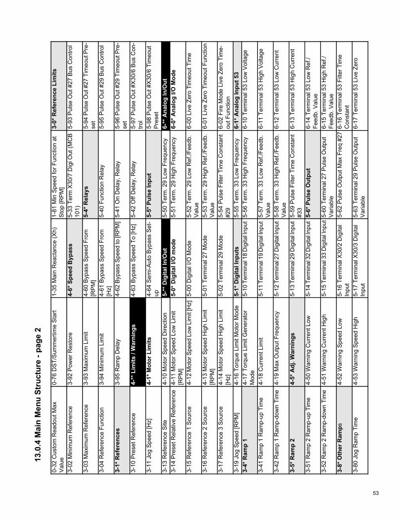
53
13.0
.4 M
ain
Men
u St
ruct
ure
- pag
e 2
0-32
Cus
tom
Rea
dout
Max
Val
ue0-
76 D
ST/
Sum
mer
time
Sta
rt1-
35 M
ain
Rea
ctan
ce (X
h)1-
81 M
in S
peed
for F
unct
ion
atS
top
[RP
M]
3-0*
Ref
eren
ce L
imits
3-02
Min
imum
Ref
eren
ce3-
92 P
ower
Res
tore
4-6*
Spe
ed B
ypas
s5-
33 T
erm
X30
/7 D
igi O
ut (M
CB
101)
5-93
Pul
se O
ut #
27 B
us C
ontro
l
3-03
Max
imum
Ref
eren
ce3-
93 M
axim
um L
imit
4-60
Byp
ass
Spe
ed F
rom
[RP
M]
5-4*
Rel
ays
5-94
Pul
se O
ut #
27 T
imeo
ut P
re-
set
3-04
Ref
eren
ce F
unct
ion
3-94
Min
imum
Lim
it4-
61 B
ypas
s S
peed
Fro
m[H
z]5-
40 F
unct
ion
Rel
ay5-
95 P
ulse
Out
#29
Bus
Con
trol
3-1*
Ref
eren
ces
3-95
Ram
p D
elay
4-62
Byp
ass
Spe
ed to
[RP
M]
5-41
On
Del
ay, R
elay
5-96
Pul
se O
ut #
29 T
imeo
ut P
re-
set
3-10
Pre
set R
efer
ence
4-**
Lim
its /
War
ning
s 4-
63 B
ypas
s S
peed
To
[Hz]
5-42
Off
Del
ay, R
elay
5-97
Pul
se O
ut #
X30
/6 B
us C
on-
trol
3-11
Jog
Spe
ed [H
z]4-
1* M
otor
Lim
its4-
64 S
emi-A
uto
Byp
ass
Set
-up
5-5*
Pul
se In
put
5-98
Pul
se O
ut #
X30
/6 T
imeo
utP
rese
t3-
13 R
efer
ence
Site
4-10
Mot
or S
peed
Dire
ctio
n5-
** D
igita
l In/
Out
5-
50 T
erm
. 29
Low
Fre
quen
cy6-
** A
nalo
g In
/Out
3-
14 P
rese
t Rel
ativ
e R
efer
ence
4-11
Mot
or S
peed
Low
Lim
it[R
PM
]5-
0* D
igita
l I/O
mod
e5-
51 T
erm
. 29
Hig
h Fr
eque
ncy
6-0*
Ana
log
I/O M
ode
3-15
Ref
eren
ce 1
Sou
rce
4-12
Mot
or S
peed
Low
Lim
it [H
z]5-
00 D
igita
l I/O
Mod
e5-
52 T
erm
. 29
Low
Ref
./Fee
db.
Val
ue6-
00 L
ive
Zero
Tim
eout
Tim
e
3-16
Ref
eren
ce 2
Sou
rce
4-13
Mot
or S
peed
Hig
h Li
mit
[RP
M]
5-01
Ter
min
al 2
7 M
ode
5-53
Ter
m. 2
9 H
igh
Ref
./Fee
db.
Val
ue6-
01 L
ive
Zero
Tim
eout
Fun
ctio
n
3-17
Ref
eren
ce 3
Sou
rce
4-14
Mot
or S
peed
Hig
h Li
mit
[Hz]
5-02
Ter
min
al 2
9 M
ode
5-54
Pul
se F
ilter
Tim
e C
onst
ant
#29
6-02
Fire
Mod
e Li
ve Z
ero
Tim
e-ou
t Fun
ctio
n3-
19 J
og S
peed
[RP
M]
4-16
Tor
que
Lim
it M
otor
Mod
e5-
1* D
igita
l Inp
uts
5-55
Ter
m. 3
3 Lo
w F
requ
ency
6-1*
Ana
log
Inpu
t 53
3-4*
Ram
p 1
4-17
Tor
que
Lim
it G
ener
ator
Mod
e5-
10 T
erm
inal
18
Dig
ital I
nput
5-56
Ter
m. 3
3 H
igh
Freq
uenc
y6-
10 T
erm
inal
53
Low
Vol
tage
3-41
Ram
p 1
Ram
p-up
Tim
e4-
18 C
urre
nt L
imit
5-11
Ter
min
al 1
9 D
igita
l Inp
ut5-
57 T
erm
. 33
Low
Ref
./Fee
db.
Val
ue6-
11 T
erm
inal
53
Hig
h V
olta
ge
3-42
Ram
p 1
Ram
p-do
wn
Tim
e4-
19 M
ax O
utpu
t Fre
quen
cy5-
12 T
erm
inal
27
Dig
ital I
nput
5-58
Ter
m. 3
3 H
igh
Ref
./Fee
db.
Val
ue6-
12 T
erm
inal
53
Low
Cur
rent
3-5*
Ram
p 2
4-5*
Adj
. War
ning
s5-
13 T
erm
inal
29
Dig
ital I
nput
5-59
Pul
se F
ilter
Tim
e C
onst
ant
#33
6-13
Ter
min
al 5
3 H
igh
Cur
rent
3-51
Ram
p 2
Ram
p-up
Tim
e4-
50 W
arni
ng C
urre
nt L
ow5-
14 T
erm
inal
32
Dig
ital I
nput
5-6*
Pul
se O
utpu
t6-
14 T
erm
inal
53
Low
Ref
./Fe
edb.
Val
ue3-
52 R
amp
2 R
amp-
dow
n Ti
me
4-51
War
ning
Cur
rent
Hig
h5-
15 T
erm
inal
33
Dig
ital I
nput
5-60
Ter
min
al 2
7 P
ulse
Out
put
Var
iabl
e6-
15 T
erm
inal
53
Hig
h R
ef./
Feed
b. V
alue
3-8*
Oth
er R
amps
4-52
War
ning
Spe
ed L
ow5-
16 T
erm
inal
X30
/2 D
igita
lIn
put
5-62
Pul
se O
utpu
t Max
Fre
q #2
76-
16 T
erm
inal
53
Filte
r Tim
eC
onst
ant
3-80
Jog
Ram
p Ti
me
4-53
War
ning
Spe
ed H
igh
5-17
Ter
min
al X
30/3
Dig
ital
Inpu
t5-
63 T
erm
inal
29
Pul
se O
utpu
tV
aria
ble
6-17
Ter
min
al 5
3 Li
ve Z
ero
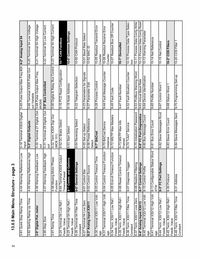
54
13.0
.5 M
ain
Men
u St
ruct
ure
- pag
e 3
3-81
Qui
ck S
top
Ram
p Ti
me
4-54
War
ning
Ref
eren
ce L
ow5-
18 T
erm
inal
X30
/4 D
igita
lIn
put
5-65
Pul
se O
utpu
t Max
Fre
q #2
96-
2* A
nalo
g In
put 5
4
3-82
Sta
rting
Ram
p U
p Ti
me
4-55
War
ning
Ref
eren
ce H
igh
5-3*
Dig
ital O
utpu
ts5-
66 T
erm
inal
X30
/6 P
ulse
Out
-pu
t Var
iabl
e6-
20 T
erm
inal
54
Low
Vol
tage
3-9*
Dig
ital P
ot. m
eter
4-56
War
ning
Fee
dbac
k Lo
w5-
30 T
erm
inal
27
Dig
ital O
ut-
put
5-68
Pul
se O
utpu
t Max
Fre
q#X
30/6
6-21
Ter
min
al 5
4 H
igh
Vol
tage
3-90
Ste
p S
ize
4-57
War
ning
Fee
dbac
k H
igh
5-31
Ter
min
al 2
9 D
igita
l Out
-pu
t5-
9* B
us C
ontr
olle
d6-
22 T
erm
inal
54
Low
Cur
rent
3-91
Ram
p Ti
me
4-58
Mis
sing
Mot
or P
hase
Func
tion
5-32
Ter
m X
30/6
Dig
i Out
(MC
B 1
01)
5-90
Dig
ital &
Rel
ay B
us C
ontro
l6-
23 T
erm
inal
54
Hig
h C
urre
nt
6-24
Ter
min
al 5
4 Lo
w R
ef./
Feed
b. V
alue
6-64
Ter
min
al X
30/8
Out
put
Tim
eout
Pre
set
8-52
DC
Bra
ke S
elec
t9-
16 P
CD
Rea
d C
onfig
urat
ion
10-*
* CA
N F
ield
bus
6-25
Ter
min
al 5
4 H
igh
Ref
./Fe
edb.
Val
ue8-
** C
omm
. and
Opt
ions
8-
53 S
tart
Sel
ect
9-18
Nod
e A
ddre
ss10
-0* C
omm
on S
ettin
gs
6-26
Ter
min
al 5
4 Fi
lter T
ime
Con
stan
t8-
0* G
ener
al S
ettin
gs8-
54 R
ever
sing
Sel
ect
9-22
Tel
egra
m S
elec
tion
10-0
0 C
AN
Pro
toco
l
6-27
Ter
min
al 5
4 Li
ve Z
ero
8-01
Con
trol S
ite8-
55 S
et-u
p S
elec
t9-
23 P
aram
eter
s fo
r Sig
nals
10-0
1 B
aud
Rat
e S
elec
t6-
3* A
nalo
g In
put X
30/1
18-
02 C
ontro
l Sou
rce
8-56
Pre
set R
efer
ence
Sel
ect
9-27
Par
amet
er E
dit
10-0
2 M
AC
ID
6-30
Ter
min
al X
30/1
1 Lo
w V
olt-
age
8-03
Con
trol T
imeo
ut T
ime
8-7*
BA
Cne
t9-
28 P
roce
ss C
ontro
l10
-05
Rea
dout
Tra
nsm
it E
rror
Cou
nter
6-31
Ter
min
al X
30/1
1 H
igh
Vol
t-ag
e8-
04 C
ontro
l Tim
eout
Fun
ctio
n8-
70 B
AC
net D
evic
eIn
stan
ce9-
44 F
ault
Mes
sage
Cou
nter
10-0
6 R
eado
ut R
ecei
ve E
rror
Cou
nter
6-34
Ter
m. X
30/1
1 Lo
w R
ef./
Feed
b. V
alue
8-05
End
-of-T
imeo
ut F
unct
ion
8-72
MS
/TP
Max
Mas
ters
9-45
Fau
lt C
ode
10-0
7 R
eado
ut B
us O
ff C
ount
er
6-35
Ter
m. X
30/1
1 H
igh
Ref
./Fe
edb.
Val
ue8-
06 R
eset
Con
trol T
imeo
ut8-
73 M
S/T
P M
ax In
foFr
ames
9-47
Fau
lt N
umbe
r10
-1* D
evic
eNet
6-36
Ter
m. X
30/1
1 Fi
lter T
ime
Con
stan
t8-
07 D
iagn
osis
Trig
ger
8-74
"I-A
m" S
ervi
ce9-
52 F
ault
Situ
atio
n C
ount
er10
-10
Pro
cess
Dat
a Ty
pe S
elec
-tio
n6-
37 T
erm
. X30
/11
Live
Zer
o8-
08 R
eado
ut F
ilter
ing
8-75
Initi
aliz
atio
n P
assw
ord
9-53
Pro
fibus
War
ning
Wor
d10
-11
Pro
cess
Dat
a C
on!g
Writ
e6-
4* A
nalo
g In
put X
30/1
28-
1* C
ontr
ol S
ettin
gs8-
8* F
C P
ort D
iagn
ostic
s9-
63 A
ctua
l Bau
d R
ate
10-1
2 P
roce
ss D
ata
Con
!g R
ead
6-40
Ter
min
al X
30/1
2 Lo
w V
olt-
age
8-10
Con
trol P
rofil
e8-
80 B
us M
essa
ge C
ount
9-64
Dev
ice
Iden
tific
atio
n10
-13
War
ning
Par
amet
er
6-41
Ter
min
al X
30/1
2 H
igh
Vol
t-ag
e8-
13 C
onfig
urab
le S
tatu
s W
ord
STW
8-81
Bus
Err
or C
ount
9-65
Pro
file
Num
ber
10-1
4 N
et R
efer
ence
6-44
Ter
m. X
30/1
2 Lo
w R
ef./
Feed
b. V
alue
8-3*
FC
Por
t Set
tings
8-82
Sla
ve M
essa
ges
Rcv
d9-
67 C
ontro
l Wor
d 1
10-1
5 N
et C
ontro
l
6-45
Ter
m. X
30/1
2 H
igh
Ref
./Fe
edb.
Val
ue8-
30 P
roto
col
8-83
Sla
ve E
rror
Cou
nt9-
68 S
tatu
s W
ord
110
-2* C
OS
Filte
rs
6-46
Ter
m. X
30/1
2 Fi
lter T
ime
Con
stan
t8-
31 A
ddre
ss8-
84 S
lave
Mes
sage
s S
ent
9-70
Pro
gram
min
g S
et-u
p10
-20
CO
S F
ilter
1

55
13.0
.6 M
ain
Men
u St
ruct
ure
- pag
e 4
6-47
Ter
m. X
30/1
2 Li
ve Z
ero
8-32
Bau
d R
ate
8-85
Sla
ve T
imeo
ut E
rror
s9-
71 P
rofib
us S
ave
Dat
a V
alue
s10
-21
CO
S F
ilter
26-
5* A
nalo
g O
utpu
t42
8-3
3 P
arity
/ S
top
Bits
8-89
Dia
gnos
tics
Cou
nt9-
72 P
rofib
usD
riveR
eset
10-2
2 C
OS
Filt
er 3
6-50
Ter
min
al 4
2 O
utpu
t8-
34 E
stim
ated
cyc
le ti
me
8-9*
Bus
Jog
/ Fe
edba
ck9-
80 D
efin
ed P
aram
eter
s (1
)10
-23
CO
S F
ilter
46-
51 T
erm
inal
42
Out
put M
inS
cale
8-35
Min
imum
Res
pons
e D
elay
8-90
Bus
Jog
1 S
peed
9-81
Def
ined
Par
amet
ers
(2)
10-3
* Par
amet
er A
cces
s
6-52
Ter
min
al 4
2 O
utpu
t Max
Sca
le8-
36 M
axim
um R
espo
nse
Del
ay8-
91 B
us J
og 2
Spe
ed9-
82 D
efin
ed P
aram
eter
s (3
)10
-30
Arr
ay In
dex
6-53
Ter
min
al 4
2 O
utpu
t Bus
Con
trol
8-37
Max
imum
Inte
r-C
har D
elay
8-94
Bus
Fee
dbac
k 1
9-83
Def
ined
Par
amet
ers
(4)
10-3
1 S
tore
Dat
a V
alue
s
6-54
Ter
min
al 4
2 O
utpu
t Tim
e-ou
t Pre
set
8-4*
FC
MC
pro
toco
l set
8-95
Bus
Fee
dbac
k 2
9-84
Def
ined
Par
amet
ers
(5)
10-3
2 D
evic
enet
Rev
isio
n
6-6*
Ana
log
Out
put X
30/8
8-40
Tel
egra
m s
elec
tion
8-96
Bus
Fee
dbac
k 3
9-90
Cha
nged
Par
amet
ers
(1)
10-3
3 S
tore
Alw
ays
6-60
Ter
min
al X
30/8
Out
put
8-42
PC
D w
rite
conf
igur
atio
n9-
** P
rofib
us
9-91
Cha
nged
Par
amet
ers
(2)
10-3
4 D
evic
eNet
Pro
duct
Cod
e6-
61 T
erm
inal
X30
/8 M
in. S
cale
8-43
PC
D re
ad c
onfig
urat
ion
9-00
Set
poin
t9-
92 C
hang
ed P
aram
eter
s (3
)10
-39
Dev
icen
et F
Par
amet
ers
6-62
Ter
min
al X
30/8
Max
. Sca
le8-
5* D
igita
l/Bus
9-07
Act
ual V
alue
9-93
Cha
nged
Par
amet
ers
(4)
11-*
* Lon
Wor
ks
6-63
Ter
min
al X
30/8
Out
put B
usC
ontro
l8-
50 C
oast
ing
Sel
ect
9-15
PC
D W
rite
Con
figur
a-tio
n9-
94 C
hang
ed p
aram
eter
s (5
)11
-0* L
onW
orks
ID
11-0
0 N
euro
n ID
14-*
* Spe
cial
Fun
ctio
ns
14-5
0 R
FI F
ilter
15-2
3 H
isto
ric L
og: D
ate
and
Tim
e15
-72
Opt
ion
in S
lot B
11-1
* LO
N F
unct
ions
14-0
* Inv
erte
r Sw
itchi
ng14
-51
DC
Lin
k C
ompe
nsa-
tion
15-3
* Ala
rm L
og15
-73
Slo
t B O
ptio
n S
W V
ersi
on
11-1
0 D
rive
Pro
file
14-0
0 S
witc
hing
Pat
tern
14-5
2 Fa
n C
ontro
l15
-30
Ala
rm L
og: E
rror
Cod
e15
-74
Opt
ion
in S
lot C
011
-15
LON
War
ning
Wor
d14
-01
Sw
itchi
ng F
requ
ency
14-5
3 Fa
n M
onito
r15
-31
Ala
rm L
og: V
alue
15-7
5 S
lot C
0 O
ptio
n S
W V
er-
sion
11-1
7 X
IF R
evis
ion
14-0
3 O
verm
odul
atio
n14
-6* A
uto
Der
ate
15-3
2 A
larm
Log
: Tim
e15
-76
Opt
ion
in S
lot C
111
-18
LonW
orks
Rev
isio
n14
-04
PW
M R
ando
m14
-60
Func
tion
at O
verte
m-
pera
ture
15-3
3 A
larm
Log
: Dat
e an
d Ti
me
15-7
7 S
lot C
1 O
ptio
n S
W V
er-
sion
11-2
* LO
N P
aram
. Acc
ess
14-1
* Mai
ns O
n/O
ff14
-61
Func
tion
at In
verte
rO
verlo
ad15
-4* D
rive
Iden
tific
atio
n15
-9* P
aram
eter
Info
11-2
1 S
tore
Dat
a V
alue
s14
-10
Mai
ns F
ailu
re14
-62
Inv.
Ove
rload
Der
ate
Cur
rent
15-4
0 FC
Typ
e15
-92
Def
ined
Par
amet
ers
13-*
* Sm
art L
ogic
14
-11
Mai
ns V
olta
ge a
t Mai
nsFa
ult
15-*
* Driv
e In
form
atio
n 15
-41
Pow
er S
ectio
n15
-93
Mod
i!ed
Par
amet
ers
13-0
* SLC
Set
tings
14-1
2 Fu
nctio
n at
Mai
ns Im
bal-
ance
15-0
* Ope
ratin
g D
ata
15-4
2 V
olta
ge15
-98
Driv
e Id
entif
icat
ion
13-0
0 S
L C
ontro
ller M
ode
14-2
* Res
et F
unct
ions
15-0
0 O
pera
ting
Hou
rs15
-43
Sof
twar
e V
ersi
on15
-99
Par
amet
er M
etad
ata
13-0
1 S
tart
Eve
nt14
-20
Res
et M
ode
15-0
1 R
unni
ng H
ours
15-4
4 O
rder
ed T
ypec
ode
Stri
ng16
-** D
ata
Rea
dout
s13
-02
Sto
p E
vent
14-2
1 A
utom
atic
Res
tart
Tim
e15
-02
kWh
Cou
nter
15-4
5 A
ctua
l Typ
ecod
e S
tring
16-0
* Gen
eral
Sta
tus
13-0
3 R
eset
SLC
14-2
2 O
pera
tion
Mod
e15
-03
Pow
er-u
ps15
-46
Adj
usta
ble
Freq
uenc
yD
rive
Ord
erin
g N
o16
-00
Con
trol W
ord

56
13.0
.7 M
ain
Men
u St
ruct
ure
- pag
e 5
13-1
* Com
para
tors
14-2
3 Ty
peco
de S
ettin
g15
-04
Ove
rtem
ps15
-47
Pow
er C
ard
Ord
erin
g N
o16
-01
Ref
eren
ce [U
nit]
13-1
0 C
ompa
rato
r Ope
rand
14-2
5 Tr
ip D
elay
at T
orqu
e Li
mit
15-0
5 O
verv
olts
15-4
8 LC
P Id
No
16-0
2 R
efer
ence
[%]
13-1
1 C
ompa
rato
r Ope
rato
r14
-26
Trip
Del
ay a
t Inv
erte
rFa
ult
15-0
6 R
eset
kW
h C
ount
er15
-49
SW
ID C
ontro
l Car
d16
-03
Sta
tus
Wor
d
13-1
2 C
ompa
rato
r Val
ue14
-28
Pro
duct
ion
Set
tings
15-0
7 R
eset
Run
ning
Hou
rsC
ount
er15
-50
SW
ID P
ower
Car
d16
-05
Mai
n A
ctua
l Val
ue [%
]
13-2
* Tim
ers
14-2
9 S
ervi
ce C
ode
15-0
8 N
umbe
r of S
tarts
15-5
1 A
dj. F
requ
ency
Driv
eS
eria
l Num
ber
16-0
9 C
usto
m R
eado
ut
13-2
0 S
L C
ontro
ller T
imer
14-3
* Cur
rent
Lim
it C
trl.
15-1
* Dat
a Lo
g Se
tting
s15
-53
Pow
er C
ard
Ser
ial N
um-
ber
16-1
* Mot
or S
tatu
s
13-4
* Log
ic R
ules
14-3
0 C
urre
nt L
im C
trl, P
ropo
r-tio
nal G
ain
15-1
0 Lo
ggin
g S
ourc
e15
-55
Ven
dor U
RL
16-1
0 P
ower
[kW
]
13-4
0 Lo
gic
Rul
e B
oole
an 1
14-3
1 C
urre
nt L
im C
trl, I
nteg
ra-
tion
Tim
e15
-11
Logg
ing
Inte
rval
15-5
6 V
endo
r Nam
e16
-11
Pow
er [h
p]
13-4
1 Lo
gic
Rul
e O
pera
tor 1
14-3
2 C
urre
nt L
im C
trl, F
ilter
Tim
e15
-12
Trig
ger E
vent
15-6
* Opt
ion
Iden
t16
-12
Mot
or V
olta
ge
13-4
2 Lo
gic
Rul
e B
oole
an 2
14-4
* Ene
rgy
Opt
imiz
ing
15-1
3 Lo
ggin
g M
ode
15-6
0 O
ptio
n M
ount
ed16
-13
Freq
uenc
y13
-43
Logi
c R
ule
Ope
rato
r 214
-40
VT
Leve
l15
-14
Sam
ples
Bef
ore
Trig
-ge
r15
-61
Opt
ion
SW
Ver
sion
16-1
4 M
otor
Cur
rent
13-4
4 Lo
gic
Rul
e B
oole
an 3
14-4
1 A
EO
Min
imum
Mag
neti-
zatio
n15
-2* H
isto
ric L
og15
-62
Opt
ion
Ord
erin
g N
o16
-15
Freq
uenc
y [%
]
13-5
* Sta
tes
14-4
2 M
inim
um A
EO
Fre
-qu
ency
15-2
0 H
isto
ric L
og: E
vent
15-6
3 O
ptio
n S
eria
l No
16-1
6 To
rque
[Nm
]
13-5
1 S
L C
ontro
ller E
vent
14-4
3 M
otor
Cos
phi
15-2
1 H
isto
ric L
og: V
alue
15-7
0 O
ptio
n in
Slo
t A16
-17
Spe
ed [R
PM
]13
-52
SL
Con
trolle
r Act
ion
14-5
* Env
ironm
ent
15-2
2 H
isto
ric L
og: T
ime
15-7
1 S
lot A
Opt
ion
SW
Ver
sion
16-1
8 M
otor
The
rmal
16-2
2 To
rque
[%]
16-6
6 D
igita
l Out
put [
bin]
18-1
* Fire
Mod
e Lo
g20
-14
Max
imum
Ref
eren
ce/
Feed
b.20
-84
On
Ref
eren
ce B
andw
idth
16-2
6 P
ower
Filt
ered
[kW
]16
-67
Pul
se In
put #
29 [H
z]18
-10
Fire
Mod
e Lo
g: E
vent
20-2
* Fee
dbac
k/Se
tpoi
nt20
-9* P
ID C
ontr
olle
r16
-27
Pow
er F
ilter
ed [h
p]16
-68
Pul
se In
put #
33 [H
z]18
-11
Fire
Mod
e Lo
g: T
ime
20-2
0 Fe
edba
ck F
unct
ion
20-9
1 P
ID A
nti W
indu
p16
-3* D
rive
Stat
us16
-69
Pul
se O
utpu
t #27
[Hz]
18-1
2 Fi
re M
ode
Log:
Dat
ean
d Ti
me
20-2
1 S
etpo
int 1
20-9
3 P
ID P
ropo
rtion
al G
ain
16-3
0 D
C L
ink
Vol
tage
16-7
0 P
ulse
Out
put #
29 [H
z]18
-3* I
nput
s &
Out
puts
20-2
2 S
etpo
int 2
20-9
4 P
ID In
tegr
al T
ime
16-3
2 B
rake
Ene
rgy
/s16
-71
Rel
ay O
utpu
t [bi
n]18
-30
Ana
log
Inpu
t X42
/120
-23
Set
poin
t 320
-95
PID
Diff
eren
tiatio
n Ti
me
16-3
3 B
rake
Ene
rgy
/2 m
in16
-72
Cou
nter
A18
-31
Ana
log
Inpu
t X42
/320
-3* F
eedb
. Adv
. Con
v.20
-96
PID
Diff
. Gai
n Li
mit
16-3
4 H
eats
ink
Tem
p.16
-73
Cou
nter
B18
-32
Ana
log
Inpu
t X42
/520
-30
Ref
riger
ant
21-*
* Ext
. Clo
sed-
loop
16
-36
Inv.
Nom
. Cur
rent
16-7
5 A
nalo
g In
X30
/11
18-3
3 A
nalo
g O
ut X
42/7
[V]
20-3
1 U
ser D
efin
ed R
efrig
eran
tA
121
-0* E
xt. C
L A
utot
unin
g
16-3
7 In
v. M
ax. C
urre
nt16
-76
Ana
log
In X
30/1
218
-34
Ana
log
Out
X42
/9 [V
]20
-32
Use
r-de
fined
Ref
riger
ant
A2
21-0
0 C
lose
d-lo
op T
ype

57
13.0
.8 M
ain
Men
u St
ruct
ure
- pag
e 6
16-3
8 S
L C
ontro
ller S
tate
16-7
7 A
nalo
g O
ut X
30/8
[mA
]18
-35
Ana
log
Out
X42
/11
[V]
20-3
3 U
ser-
defin
ed R
efrig
eran
tA
321
-01
PID
Per
form
ance
16-3
9 C
ontro
l Car
d Te
mp.
16-8
* Fie
ldbu
s &
FC
Por
t18
-36
Ana
log
Inpu
t X48
/2[m
A]
20-3
4 D
uct 1
Are
a [m
2]21
-02
PID
Out
put C
hang
e
16-4
0 Lo
ggin
g B
uffe
r Ful
l16
-80
Fiel
dbus
CTW
118
-37
Tem
p. In
put X
48/4
20-3
5 D
uct 1
Are
a [in
2]21
-03
Min
imum
Fee
dbac
k Le
vel
16-4
3 Ti
med
Act
ions
Sta
tus
16-8
2 Fi
eldb
us R
EF
118
-38
Tem
p. In
put X
48/7
20-3
6 D
uct 2
Are
a [m
2]21
-04
Max
imum
Fee
dbac
k Le
vel
16-4
9 C
urre
nt F
ault
Sou
rce
16-8
4 C
omm
. Opt
ion
STW
18-3
9 Te
mp.
Inpu
t X48
/10
20-3
7 D
uct 2
Are
a [in
2]21
-09
PID
Aut
otun
ing
16-5
* Ref
. & F
eedb
.16
-85
FC P
ort C
TW 1
18-5
* R
ef. &
Fee
db.
20-3
8 A
ir D
ensi
ty F
acto
r [%
]21
-1* E
xt. C
L 1
Ref
./Fb.
16-5
0 E
xter
nal R
efer
ence
16-8
6 FC
Por
t RE
F 1
18-5
0 S
enso
rless
Rea
dout
[uni
t]20
-6* S
enso
rless
21-1
0 E
xt. 1
Ref
./Fee
dbac
k U
nit
16-5
2 Fe
edba
ck [U
nit]
16-9
* Dia
gnos
is R
eado
uts
20-*
* Driv
e C
lose
d-lo
op
20-6
0 S
enso
rless
Uni
t21
-11
Ext
. 1 M
inim
um R
efer
ence
16-5
3 D
igi P
ot R
efer
ence
16-9
0 A
larm
Wor
d20
-0* F
eedb
ack
20-6
9 S
enso
rless
Info
rmat
ion
21-1
2 E
xt. 1
Max
imum
Ref
er-
ence
16-5
4 Fe
edba
ck 1
[Uni
t] 2
16-9
1 A
larm
Wor
d20
-00
Feed
back
1 S
ourc
e20
-7* P
ID A
utot
unin
g21
-13
Ext
. 1 R
efer
ence
Sou
rce
16-5
5 Fe
edba
ck 2
[Uni
t]16
-92
War
ning
Wor
d20
-01
Feed
back
1 C
onve
r-si
on20
-70
Clo
sed-
loop
Typ
e21
-14
Ext
. 1 F
eedb
ack
Sou
rce
16-5
6 Fe
edba
ck 3
[Uni
t]16
-93
War
ning
Wor
d 2
20-0
2 Fe
edba
ck 1
Sou
rce
Uni
t20
-71
PID
Per
form
ance
21-1
5 E
xt. 1
Set
poin
t
16-5
8 P
ID O
utpu
t [%
]16
-94
Ext
. Sta
tus
Wor
d20
-03
Feed
back
2 S
ourc
e20
-72
PID
Out
put C
hang
e21
-17
Ext
. 1 R
efer
ence
[Uni
t]16
-6* I
nput
s &
Out
puts
16-9
6 M
aint
enan
ce W
ord
20-0
4 Fe
edba
ck 2
Con
ver-
sion
20-7
3 M
inim
um F
eedb
ack
Leve
l21
-18
Ext
. 1 F
eedb
ack
[Uni
t]
16-6
0 D
igita
l Inp
ut18
-** I
nfo
& R
eado
uts
20-0
5 Fe
edba
ck 2
Sou
rce
Uni
t20
-74
Max
imum
Fee
dbac
k Le
vel
21-1
9 E
xt. 1
Out
put [
%]
16-6
1 Te
rmin
al 5
3 S
witc
h S
ettin
g 18
-0* M
aint
enan
ce L
og20
-06
Feed
back
3 S
ourc
e20
-79
PID
Aut
otun
ing
21-2
* Ext
. CL
1 PI
D16
-62
Ana
log
Inpu
t 53
18-0
0 M
aint
enan
ce L
og: I
tem
20-0
7 Fe
edba
ck 3
Con
ver-
sion
20-8
* PID
Bas
ic S
ettin
gs21
-20
Ext
. 1 N
orm
al/In
vers
eC
ontro
l16
-63
Term
inal
54
Sw
itch
Set
ting
18-0
1 M
aint
enan
ce L
og: A
ctio
n20
-08
Feed
back
3 S
ourc
eU
nit
20-8
1 P
ID N
orm
al/ I
nver
se C
on-
trol
21-2
1 E
xt. 1
Pro
porti
onal
Gai
n
16-6
4 A
nalo
g In
put 5
418
-02
Mai
nten
ance
Log
: Tim
e20
-12
Ref
eren
ce/F
eedb
ack
Uni
t20
-82
PID
Sta
rt S
peed
[RP
M]
21-2
2 E
xt. 1
Inte
gral
Tim
e
16-6
5 A
nalo
g O
utpu
t 42
[mA
]18
-03
Mai
nten
ance
Log
: Dat
ean
d Ti
me
20-1
3 M
inim
um R
efer
ence
/Fe
edb.
20-8
3 P
ID S
tart
Spe
ed [H
z]21
-23
Ext
. 1 D
iffer
enta
tion
Tim
e
21-2
4 E
xt. 1
Dif.
Gai
n Li
mit
21-6
0 E
xt. 3
Nor
mal
/Inve
rse
Con
trol
22-4
* Sle
ep M
ode
22-8
6 S
peed
at D
esig
n P
oint
[Hz]
23-6
0 Tr
end
Var
iabl
e
21-3
* E
xt. C
L 2
Ref
./Fb.
21-6
1 E
xt. 3
Pro
porti
onal
Gai
n22
-40
Min
imum
Run
Tim
e22
-87
Pre
ssur
e at
No-
Flow
Spe
ed23
-61
Con
tinuo
us B
in D
ata
21-3
0 E
xt. 2
Ref
./Fee
dbac
k U
nit
21-6
2 E
xt. 3
Inte
gral
Tim
e22
-41
Min
imum
Sle
ep T
ime
22-8
8 P
ress
ure
at R
ated
Spe
ed23
-62
Tim
ed B
in D
ata
21-3
1 E
xt. 2
Min
imum
Ref
eren
ce21
-63
Ext
. 3 D
iffer
enta
tion
Tim
e22
-42
Wak
e-up
Spe
ed[R
PM
]22
-89
Flow
at D
esig
n P
oint
23-6
3 Ti
med
Per
iod
Sta
rt
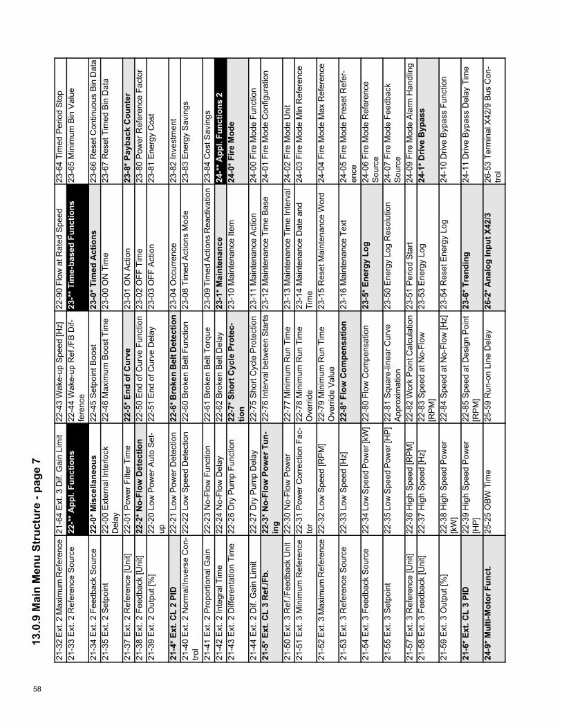
58
13.0
.9 M
ain
Men
u St
ruct
ure
- pag
e 7
21-3
2 E
xt. 2
Max
imum
Ref
eren
ce21
-64
Ext
. 3 D
if. G
ain
Lim
it22
-43
Wak
e-up
Spe
ed [H
z]22
-90
Flow
at R
ated
Spe
ed23
-64
Tim
ed P
erio
d S
top
21-3
3 E
xt. 2
Ref
eren
ce S
ourc
e22
-** A
ppl.
Func
tions
22
-44
Wak
e-up
Ref
./FB
Dif-
fere
nce
23-*
* Tim
e-ba
sed
Func
tions
23
-65
Min
imum
Bin
Val
ue
21-3
4 E
xt. 2
Fee
dbac
k S
ourc
e22
-0* M
isce
llane
ous
22-4
5 S
etpo
int B
oost
23-0
* Tim
ed A
ctio
ns23
-66
Res
et C
ontin
uous
Bin
Dat
a21
-35
Ext
. 2 S
etpo
int
22-0
0 E
xter
nal I
nter
lock
Del
ay22
-46
Max
imum
Boo
st T
ime
23-0
0 O
N T
ime
23-6
7 R
eset
Tim
ed B
in D
ata
21-3
7 E
xt. 2
Ref
eren
ce [U
nit]
22-0
1 P
ower
Filt
er T
ime
22-5
* End
of C
urve
23-0
1 O
N A
ctio
n23
-8* P
ayba
ck C
ount
er21
-38
Ext
. 2 F
eedb
ack
[Uni
t]22
-2* N
o-Fl
ow D
etec
tion
22-5
0 E
nd o
f Cur
ve F
unct
ion
23-0
2 O
FF T
ime
23-8
0 P
ower
Ref
eren
ce F
acto
r21
-39
Ext
. 2 O
utpu
t [%
]22
-20
Low
Pow
er A
uto
Set
-up
22-5
1 E
nd o
f Cur
ve D
elay
23-0
3 O
FF A
ctio
n23
-81
Ene
rgy
Cos
t
21-4
* Ext
. CL
2 PI
D22
-21
Low
Pow
er D
etec
tion
22-6
* Bro
ken
Bel
t Det
ectio
n23
-04
Occ
urre
nce
23-8
2 In
vest
men
t21
-40
Ext
. 2 N
orm
al/In
vers
e C
on-
trol
22-2
2 Lo
w S
peed
Det
ectio
n22
-60
Bro
ken
Bel
t Fun
ctio
n23
-08
Tim
ed A
ctio
ns M
ode
23-8
3 E
nerg
y S
avin
gs
21-4
1 E
xt. 2
Pro
porti
onal
Gai
n22
-23
No-
Flow
Fun
ctio
n22
-61
Bro
ken
Bel
t Tor
que
23-0
9 Ti
med
Act
ions
Rea
ctiv
atio
n23
-84
Cos
t Sav
ings
21-4
2 E
xt. 2
Inte
gral
Tim
e22
-24
No-
Flow
Del
ay22
-62
Bro
ken
Bel
t Del
ay23
-1* M
aint
enan
ce24
-** A
ppl.
Func
tions
221
-43
Ext
. 2 D
iffer
enta
tion
Tim
e22
-26
Dry
Pum
p Fu
nctio
n22
-7* S
hort
Cyc
le P
rote
c-tio
n23
-10
Mai
nten
ance
Item
24-0
* Fire
Mod
e
21-4
4 E
xt. 2
Dif.
Gai
n Li
mit
22-2
7 D
ry P
ump
Del
ay22
-75
Sho
rt C
ycle
Pro
tect
ion
23-1
1 M
aint
enan
ce A
ctio
n24
-00
Fire
Mod
e Fu
nctio
n21
-5* E
xt. C
L 3
Ref
./Fb.
22-3
* No-
Flow
Pow
er T
un-
ing
22-7
6 In
terv
al b
etw
een
Sta
rts23
-12
Mai
nten
ance
Tim
e B
ase
24-0
1 Fi
re M
ode
Con
figur
atio
n
21-5
0 E
xt. 3
Ref
./Fee
dbac
k U
nit
22-3
0 N
o-Fl
ow P
ower
22-7
7 M
inim
um R
un T
ime
23-1
3 M
aint
enan
ce T
ime
Inte
rval
24-0
2 Fi
re M
ode
Uni
t21
-51
Ext
. 3 M
inim
um R
efer
ence
22-3
1 P
ower
Cor
rect
ion
Fac-
tor
22-7
8 M
inim
um R
un T
ime
Ove
rrid
e23
-14
Mai
nten
ance
Dat
e an
dTi
me
24-0
3 Fi
re M
ode
Min
Ref
eren
ce
21-5
2 E
xt. 3
Max
imum
Ref
eren
ce22
-32
Low
Spe
ed [R
PM
]22
-79
Min
imum
Run
Tim
eO
verr
ide
Val
ue23
-15
Res
et M
aint
enan
ce W
ord
24-0
4 Fi
re M
ode
Max
Ref
eren
ce
21-5
3 E
xt. 3
Ref
eren
ce S
ourc
e22
-33
Low
Spe
ed [H
z]22
-8* F
low
Com
pens
atio
n23
-16
Mai
nten
ance
Tex
t24
-05
Fire
Mod
e P
rese
t Ref
er-
ence
21-5
4 E
xt. 3
Fee
dbac
k S
ourc
e22
-34
Low
Spe
ed P
ower
[kW
]22
-80
Flow
Com
pens
atio
n23
-5* E
nerg
y Lo
g24
-06
Fire
Mod
e R
efer
ence
Sou
rce
21-5
5 E
xt. 3
Set
poin
t22
-35
Low
Spe
ed P
ower
[HP
]22
-81
Squ
are-
linea
r Cur
veA
ppro
xim
atio
n23
-50
Ene
rgy
Log
Res
olut
ion
24-0
7 Fi
re M
ode
Feed
back
Sou
rce
21-5
7 E
xt. 3
Ref
eren
ce [U
nit]
22-3
6 H
igh
Spe
ed [R
PM
]22
-82
Wor
k P
oint
Cal
cula
tion
23-5
1 P
erio
d S
tart
24-0
9 Fi
re M
ode
Ala
rm H
andl
ing
21-5
8 E
xt. 3
Fee
dbac
k [U
nit]
22-3
7 H
igh
Spe
ed [H
z]22
-83
Spe
ed a
t No-
Flow
[RP
M]
23-5
3 E
nerg
y Lo
g24
-1* D
rive
Byp
ass
21-5
9 E
xt. 3
Out
put [
%]
22-3
8 H
igh
Spe
ed P
ower
[kW
]22
-84
Spe
ed a
t No-
Flow
[Hz]
23-5
4 R
eset
Ene
rgy
Log
24-1
0 D
rive
Byp
ass
Func
tion
21-6
* Ext
. CL
3 PI
D22
-39
Hig
h S
peed
Pow
er[H
P]
22-8
5 S
peed
at D
esig
n P
oint
[RP
M]
23-6
* Tre
ndin
g24
-11
Driv
e B
ypas
s D
elay
Tim
e
24-9
* Mul
ti-M
otor
Fun
ct.
25-2
5 O
BW
Tim
e25
-59
Run
-on
Line
Del
ay26
-2* A
nalo
g In
put X
42/3
26-5
3 Te
rmin
al X
42/9
Bus
Con
-tro
l
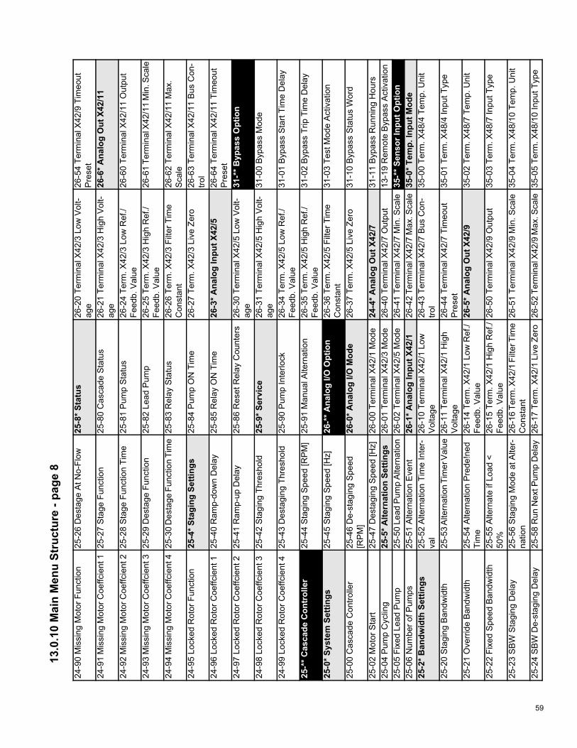
59
13.0
.10
Mai
n M
enu
Stru
ctur
e - p
age
8
24-9
0 M
issi
ng M
otor
Fun
ctio
n25
-26
Des
tage
At N
o-Fl
ow25
-8* S
tatu
s26
-20
Term
inal
X42
/3 L
ow V
olt-
age
26-5
4 Te
rmin
al X
42/9
Tim
eout
Pre
set
24-9
1 M
issi
ng M
otor
Coe
ffcie
nt 1
25-2
7 S
tage
Fun
ctio
n25
-80
Cas
cade
Sta
tus
26-2
1 Te
rmin
al X
42/3
Hig
h V
olt-
age
26-6
* Ana
log
Out
X42
/11
24-9
2 M
issi
ng M
otor
Coe
ffcie
nt 2
25-2
8 S
tage
Fun
ctio
n Ti
me
25-8
1 P
ump
Sta
tus
26-2
4 Te
rm. X
42/3
Low
Ref
./Fe
edb.
Val
ue26
-60
Term
inal
X42
/11
Out
put
24-9
3 M
issi
ng M
otor
Coe
ffcie
nt 3
25-2
9 D
esta
ge F
unct
ion
25-8
2 Le
ad P
ump
26-2
5 Te
rm. X
42/3
Hig
h R
ef./
Feed
b. V
alue
26-6
1 Te
rmin
al X
42/1
1 M
in. S
cale
24-9
4 M
issi
ng M
otor
Coe
ffcie
nt 4
25-3
0 D
esta
ge F
unct
ion
Tim
e25
-83
Rel
ay S
tatu
s26
-26
Term
. X42
/3 F
ilter
Tim
eC
onst
ant
26-6
2 Te
rmin
al X
42/1
1 M
ax.
Sca
le24
-95
Lock
ed R
otor
Fun
ctio
n25
-4* S
tagi
ng S
ettin
gs25
-84
Pum
p O
N T
ime
26-2
7 Te
rm. X
42/3
Liv
e Ze
ro26
-63
Term
inal
X42
/11
Bus
Con
-tro
l24
-96
Lock
ed R
otor
Coe
ffcie
nt 1
25-4
0 R
amp-
dow
n D
elay
25-8
5 R
elay
ON
Tim
e26
-3* A
nalo
g In
put X
42/5
26-6
4 Te
rmin
al X
42/1
1 Ti
meo
utP
rese
t24
-97
Lock
ed R
otor
Coe
ffcie
nt 2
25-4
1 R
amp-
up D
elay
25-8
6 R
eset
Rel
ay C
ount
ers
26-3
0 Te
rmin
al X
42/5
Low
Vol
t-ag
e31
-** B
ypas
s O
ptio
n
24-9
8 Lo
cked
Rot
or C
oeffc
ient
325
-42
Sta
ging
Thr
esho
ld25
-9* S
ervi
ce26
-31
Term
inal
X42
/5 H
igh
Vol
t-ag
e31
-00
Byp
ass
Mod
e
24-9
9 Lo
cked
Rot
or C
oeffc
ient
425
-43
Des
tagi
ng T
hres
hold
25-9
0 P
ump
Inte
rlock
26-3
4 Te
rm. X
42/5
Low
Ref
./Fe
edb.
Val
ue31
-01
Byp
ass
Sta
rt Ti
me
Del
ay
25-*
* Cas
cade
Con
trol
ler
25-4
4 S
tagi
ng S
peed
[RP
M]
25-9
1 M
anua
l Alte
rnat
ion
26-3
5 Te
rm. X
42/5
Hig
h R
ef./
Feed
b. V
alue
31-0
2 B
ypas
s Tr
ip T
ime
Del
ay
25-0
* Sys
tem
Set
tings
25-4
5 S
tagi
ng S
peed
[Hz]
26-*
* Ana
log
I/O O
ptio
n 26
-36
Term
. X42
/5 F
ilter
Tim
eC
onst
ant
31-0
3 Te
st M
ode
Act
ivat
ion
25-0
0 C
asca
de C
ontro
ller
25-4
6 D
e-st
agin
g S
peed
[RP
M]
26-0
* Ana
log
I/O M
ode
26-3
7 Te
rm. X
42/5
Liv
e Ze
ro31
-10
Byp
ass
Sta
tus
Wor
d
25-0
2 M
otor
Sta
rt25
-47
Des
tagi
ng S
peed
[Hz]
26-0
0 Te
rmin
al X
42/1
Mod
e24
-4* A
nalo
g O
ut X
42/7
31-1
1 B
ypas
s R
unni
ng H
ours
25-0
4 P
ump
Cyc
ling
25-5
* Alte
rnat
ion
Setti
ngs
26-0
1 Te
rmin
al X
42/3
Mod
e26
-40
Term
inal
X42
/7 O
utpu
t13
-19
Rem
ote
Byp
ass
Act
ivat
ion
25-0
5 Fi
xed
Lead
Pum
p25
-50
Lead
Pum
p A
ltern
atio
n26
-02
Term
inal
X42
/5 M
ode
26-4
1 Te
rmin
al X
42/7
Min
. Sca
le35
-** S
enso
r Inp
ut O
ptio
n 25
-06
Num
ber o
f Pum
ps25
-51
Alte
rnat
ion
Eve
nt26
-1* A
nalo
g In
put X
42/1
26-4
2 Te
rmin
al X
42/7
Max
. Sca
le
35-0
* Tem
p. In
put M
ode
25-2
* Ban
dwid
th S
ettin
gs25
-52
Alte
rnat
ion
Tim
e In
ter-
val
26-1
0 Te
rmin
al X
42/1
Low
Vol
tage
26-4
3 Te
rmin
al X
42/7
Bus
Con
-tro
l35
-00
Term
. X48
/4 T
emp.
Uni
t
25-2
0 S
tagi
ng B
andw
idth
25-5
3 A
ltern
atio
n Ti
mer
Val
ue26
-11
Term
inal
X42
/1 H
igh
Vol
tage
26-4
4 Te
rmin
al X
42/7
Tim
eout
Pre
set
35-0
1 Te
rm. X
48/4
Inpu
t Typ
e
25-2
1 O
verr
ide
Ban
dwid
th25
-54
Alte
rnat
ion
Pre
de!n
edTi
me
26-1
4 Te
rm. X
42/1
Low
Ref
./Fe
edb.
Val
ue26
-5* A
nalo
g O
ut X
42/9
35-0
2 Te
rm. X
48/7
Tem
p. U
nit
25-2
2 Fi
xed
Spe
ed B
andw
idth
25-5
5 A
ltern
ate
if Lo
ad <
50%
26-1
5 Te
rm. X
42/1
Hig
h R
ef./
Feed
b. V
alue
26-5
0 Te
rmin
al X
42/9
Out
put
35-0
3 Te
rm. X
48/7
Inpu
t Typ
e
25-2
3 S
BW
Sta
ging
Del
ay25
-56
Sta
ging
Mod
e at
Alte
r-na
tion
26-1
6 Te
rm. X
42/1
Filt
er T
ime
Con
stan
t26
-51
Term
inal
X42
/9 M
in. S
cale
35-0
4 Te
rm. X
48/1
0 Te
mp.
Uni
t
25-2
4 S
BW
De-
stag
ing
Del
ay25
-58
Run
Nex
t Pum
p D
elay
26-1
7 Te
rm. X
42/1
Liv
e Ze
ro26
-52
Term
inal
X42
/9 M
ax. S
cale
35-0
5 Te
rm. X
48/1
0 In
put T
ype
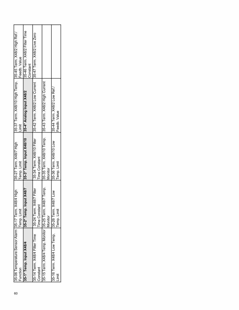
60
35-0
6 Te
mpe
ratu
re S
enso
r Ala
rm
Func
tion
35-1
7 Te
rm. X
48/4
Hig
hTe
mp.
Lim
it35
-27
Term
. X48
/7 H
igh
Tem
p. L
imit
35-3
7 Te
rm. X
48/1
0 H
igh
Tem
p.Li
mit
35-4
5 Te
rm. X
48/2
Hig
h R
ef./
Feed
b. V
alue
35-1
* Tem
p. In
put X
48/4
35-2
* Tem
p. In
put X
48/7
35-3
* Tem
p. In
put X
48/1
035
-4* A
nalo
g In
put X
48/2
35-4
6 Te
rm. X
48/2
Filt
er T
ime
Con
stan
t35
-14
Term
. X48
/4 F
ilter
Tim
eC
onst
ant
35-2
4 Te
rm. X
48/7
Filt
erTi
me
Con
stan
t35
-34
Term
. X48
/10
Filte
rTi
me
Con
stan
t35
-42
Term
. X48
/2 L
ow C
urre
nt35
-47
Term
. X48
/2 L
ive
Zero
35-1
5 Te
rm. X
48/4
Tem
p. M
onito
r 35
-25
Term
. X48
/7 T
emp.
M
onito
r35
-35
Term
. X48
/10
Tem
p.M
onito
r35
-43
Term
. X48
/2 H
igh
Cur
rent
35-1
6 Te
rm. X
48/4
Low
Tem
p.Li
mit
35-2
6 Te
rm. X
48/7
Low
Tem
p. L
imit
35-3
6 Te
rm. X
48/1
0 Lo
wTe
mp.
Lim
it35
-44
Term
. X48
/2 L
ow R
ef./
Feed
b. V
alue
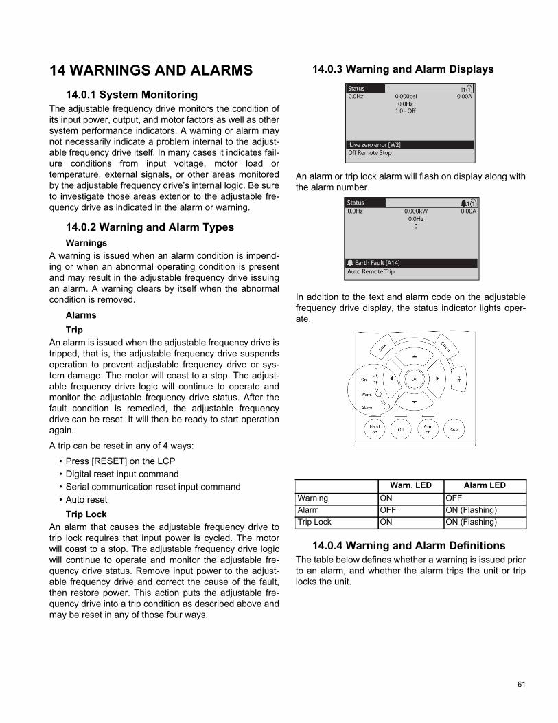
61
14 WARNINGS AND ALARMS14.0.1 System Monitoring
The adjustable frequency drive monitors the condition of its input power, output, and motor factors as well as other system performance indicators. A warning or alarm may not necessarily indicate a problem internal to the adjust-able frequency drive itself. In many cases it indicates fail-ure conditions from input voltage, motor load or temperature, external signals, or other areas monitored by the adjustable frequency drive’s internal logic. Be sure to investigate those areas exterior to the adjustable fre-quency drive as indicated in the alarm or warning.
14.0.2 Warning and Alarm TypesWarnings
A warning is issued when an alarm condition is impend-ing or when an abnormal operating condition is present and may result in the adjustable frequency drive issuing an alarm. A warning clears by itself when the abnormal condition is removed.
AlarmsTrip
An alarm is issued when the adjustable frequency drive is tripped, that is, the adjustable frequency drive suspends operation to prevent adjustable frequency drive or sys-tem damage. The motor will coast to a stop. The adjust-able frequency drive logic will continue to operate and monitor the adjustable frequency drive status. After the fault condition is remedied, the adjustable frequency drive can be reset. It will then be ready to start operation again.
A trip can be reset in any of 4 ways:
• Press [RESET] on the LCP• Digital reset input command• Serial communication reset input command• Auto reset
Trip LockAn alarm that causes the adjustable frequency drive to trip lock requires that input power is cycled. The motor will coast to a stop. The adjustable frequency drive logic will continue to operate and monitor the adjustable fre-quency drive status. Remove input power to the adjust-able frequency drive and correct the cause of the fault, then restore power. This action puts the adjustable fre-quency drive into a trip condition as described above and may be reset in any of those four ways.
14.0.3 Warning and Alarm Displays
An alarm or trip lock alarm will flash on display along with the alarm number.
In addition to the text and alarm code on the adjustable frequency drive display, the status indicator lights oper-ate.
14.0.4 Warning and Alarm DefinitionsThe table below defines whether a warning is issued prior to an alarm, and whether the alarm trips the unit or trip locks the unit.
Warn. LED Alarm LEDWarning ON OFFAlarm OFF ON (Flashing)Trip Lock ON ON (Flashing)

62
Table 9: Alarm/Warning Code List
No. Description Warning Alarm/Trip Alarm/Trip Lock Parameter Reference
1 10 Volts low X2 Live zero error (X) (X) 6-014 Mains phase loss (X) (X) (X) 14-125 DC link voltage high X6 DC link voltage low X7 DC overvoltage X X8 DC undervoltage X X9 Inverter overloaded X X10 Motor ETR overtemperature (X) (X) 1-9011 Thrmstr overld (X) (X) 1-9012 Torque limit X X13 Overcurrent X X X14 Ground fault X X X15 Hardware mismatch X X16 Short Circuit X X17 Control word timeout (X) (X) 8-0423 Internal Fan Fault X24 External Fan Fault X 14-5325 Brake resistor short-circuited X26 Brake resistor power limit (X) (X) 2-1327 Brake chopper short-circuited X X28 Brake check (X) (X) 2-1529 Drive overtemperature X X X30 Motor phase U missing (X) (X) (X) 4-5831 Motor phase V missing (X) (X) (X) 4-5832 Motor phase W missing (X) (X) (X) 4-5833 Inrush fault X X34 Fieldbus communication fault X X35 Out of frequency range X X36 Mains failure X X37 Phase Imbalance X X38 Internal fault X X39 Heatsink sensor X X40 Overload of Digital Output Terminal
27 (X) 5-00, 5-01
41 Overload of Digital Output Terminal 29
(X) 5-00, 5-02
42 Overload of Digital Output On X30/6 (X) 5-3242 Overload of Digital Output On X30/7 (X) 5-3346 Pwr. card supply X X47 24 V supply low X X X48 1.8 V supply low X X 49 Speed limit X (X) 1-8650 AMA calibration failed X51 AMA check Unom and Inom X52 AMA low Inom X53 AMA motor too big X

63
(X) Dependent on parameter1) Cannot be Auto reset via 14-20 Reset Mode
No. Description Warning Alarm/Trip Alarm/Trip Lock Parameter
Reference54 AMA motor too small X55 AMA Parameter out of range X56 AMA interrupted by user X57 AMA timeout X58 AMA internal fault X X59 Current limit X60 External Interlock X62 Output Frequency at Maximum
Limit X
64 Voltage Limit X65 Control Board Overtemperature X X X66 Heatsink Temperature Low X67 Option Configuration has Changed X69 Pwr. Card Temp X X70 Illegal FC configuration X71 PTC 1 Safe Stop X X1)
72 Dangerous Failure X1)
73 Safe Stop Auto Restart76 Power Unit Set-up X79 Illegal PS config X X 80 Drive Initialized to Default Value X91 Analog input 54 wrong settings X92 No-Flow X X 22-2*93 Dry Pump X X 22-2*94 End of Curve X X 22-5*95 Broken Belt X X 22-6*96 Start Delayed X 22-7*97 Stop Delayed X 22-7*98 Clock Fault X 0-7*201 Fire M was Active202 Fire M Limits Exceeded203 Missing Motor204 Locked Rotor243 Brake IGBT X X244 Heatsink temp X X X245 Heatsink sensor X X 246 Pwr.card supply X X 247 Pwr.card temp X X 248 Illegal PS config X X 250 New spare parts X251 New Type Code X X

64
14.0.5 Fault MessagesThe warning/alarm information below defines the warn-ing/alarm condition, provides the probable cause for the condition, and details a remedy or troubleshooting proce-dure.
WARNING 1, 10 volts low
The control card voltage is below 10 V from terminal 50. Remove some of the load from terminal 50, as the 10 V supply is overloaded. Max. 15 mA or minimum 590 Ohms. This condition can be caused by a short in a con-nected potentiometer or improper wiring of the potenti-ometer.
TroubleshootingRemove the wiring from terminal 50. If the warning clears, the problem is with the customer wiring. If the warning does not clear, replace the control card.
WARNING/ALARM 2, Live zero error This warning or alarm will only appear if programmed by the user in 6-01 Live Zero Timeout Function. The signal on one of the analog inputs is less than 50% of the mini-mum value programmed for that input. This condition can be caused by broken wiring or faulty device sending the signal.
TroubleshootingCheck connections on all the analog input terminals. Control card terminals 53 and 54 for signals, terminal 55 common. MCB 101 terminals 11 and 12 for signals, ter-minal 10 common. MCB 109 terminals 1, 3, 5 for signals, terminals 2, 4, 6 common).
Check that the adjustable frequency drive programming and switch settings match the analog signal type.
Perform Input Terminal Signal Test.
WARNING/ALARM 4, Mains phase loss
A phase is missing on the supply side, or the line voltage imbalance is too high. This message also appears for a fault in the input recti!er on the adjustable frequency drive. Options are programmed at 14-12 Function at Mains Imbalance.
TroubleshootingCheck the supply voltage and supply currents to the adjustable frequency drive.
WARNING 5, DC link voltage high
The intermediate circuit voltage (DC) is higher than the high voltage warning limit. The limit is dependent on the adjustable frequency drive voltage rating. The adjustable frequency drive is still active.
WARNING 6, DC link voltage low
The intermediate circuit voltage (DC) is lower than the low voltage warning limit. The limit is dependent on the adjustable frequency drive voltage rating. The adjustable frequency drive is still active.
WARNING/ALARM 7, DC overvoltage
If the intermediate circuit voltage exceeds the limit, the adjustable frequency drive trips after a time.
TroubleshootingConnect a brake resistor
Extend the ramp time
Change the ramp type
Activate functions in 2-10 Brake Function
Increase 14-26 Trip Delay at Inverter Fault
WARNING/ALARM 8, DC undervoltage
If the intermediate circuit voltage (DC) drops below the undervoltage limit, the adjustable frequency drive checks if a 24 VDC backup supply is connected. If no 24 VDC backup supply is connected, the adjustable frequency drive trips after a !xed time delay. The time delay varies with unit size.
TroubleshootingCheck that the supply voltage matches the
adjustable frequency drive voltage.
Perform Input voltage test
Perform soft charge and recti!er circuit test
WARNING/ALARM 9, Inverter overloadThe adjustable frequency drive is about to cut out because of an overload (current too high for too long). The counter for electronic, thermal inverter protection gives a warning at 98% and trips at 100%, while giving an alarm. The adjustable frequency drive cannot be reset until the counter is below 90%.
The fault is that the adjustable frequency drive has been overloaded by more than 100% for too long.
TroubleshootingCompare the output current shown on the LCP with the adjustable frequency drive rated current.
Compare the output current shown on the LCP with mea-sured motor current.

65
Display the Thermal Drive Load on the LCP and monitor the value. When running above the adjustable frequency drive continuous current rating, the counter should increase. When running below the adjustable frequency drive continuous current rating, the counter should decrease.
See the derating section in the Design Guide for more details if a high switching frequency is required.
WARNING/ALARM 10, Motor Overload Temperature According to the electronic thermal protection (ETR), the motor is too hot. Select whether the adjustable frequency drive gives a warning or an alarm when the counter reaches 100% in 1-90 Motor Thermal Protection. The fault occurs when the motor is overloaded by more than 100% for too long.
Troubleshooting
• Check for motor overheating.• Check if the motor is mechanically overloaded.• Check that the motor current set in 1-24 Motor Cur-
rent is correct.• Ensure that Motor data in parameters 1-20 through
1-25 are set correctly.• If an external fan is in use, check in 1-91 Motor Exter-
nal Fan that it is selected.• Running AMA in 1-29 Automatic Motor Adaptation
(AMA) may tune the adjustable frequency drive to themotor more accurately and reduce thermal loading.
WARNING/ALARM 11, Thermistor overload The thermistor might be disconnected. Select whether the adjustable frequency drive gives a warning or an alarm in 1-90 Motor Thermal Protection.
Troubleshooting
• Check for motor overheating.• Check if the motor is mechanically overloaded.• When using terminal 53 or 54, check that the therm-
istor is connected correctly between either terminal53 or 54 (analog voltage input) and terminal 50 (+10V supply) and that the terminal switch for 53 or 54 isset for voltage. Check 1-93 Thermistor Sourceselects terminal 53 or 54.
• When using digital inputs 18 or 19, check that thethermistor is connected correctly between either ter-minal 18 or 19 (digital input PNP only) and terminal50. Check 1-93 Thermistor Source selects terminal18 or 19.
WARNING/ALARM 12, Torque limit The torque has exceeded the value in 4-16 Torque Limit Motor Mode or the value in 4-17 Torque Limit Generator Mode. 14-25 Trip Delay at Torque Limit can change this from a warning only condition to a warning followed by an alarm.
Troubleshooting
• If the motor torque limit is exceeded during ramp-up,extend the ramp-up time.
• If the generator torque limit is exceeded during ramp-down, extend the ramp-down time.
• If torque limit occurs while running, possibly increasethe torque limit. Be sure the system can operatesafely at a higher torque.
• Check the application for excessive current draw onthe motor.
WARNING/ALARM 13, Overcurrent The inverter peak current limit (approx. 200% of the rated current) is exceeded. The warning lasts about 1.5 sec. Then the adjustable frequency drive trips and issues an alarm. This fault may be caused by shock loading or fast acceleration with high inertia loads. If extended mechan ical brake control is selected, trip can be reset externally.
Troubleshooting
• Remove power and check if the motor shaft can beturned.
• Make sure that the motor size matches the adjust-able frequency drive.
• Check parameters 1-20 through 1-25 for correctmotor data.
WARNING/ALARM 14, Ground FaultThere is current from the output phases to ground, either in the cable between the adjustable frequency drive and the motor or in the motor itself.
Troubleshooting
• Remove power to the adjustable frequency drive andrepair the ground fault.
• Check for ground faults in the motor by measuringthe resistance to ground of the motor leads and themotor with a megohmmeter.
WARNING/ALARM 15, Hardware MismatchA fitted option is not operational with the present control board hardware or software.
Record the value of the following parameters and contact your Danfoss supplier:
15-40 FC Type
15-41 Power Section
66
15-42 Voltage
15-43 Software Version
15-45 Actual Typecode String
15-49 SW ID Control Card
15-50 SW ID Power Card
15-60 Option Mounted
15-61 Option SW Version
WARNING/ALARM 16, Short CircuitThere is a short circuit in the motor or motor wiring. Remove power to the adjustable frequency drive and repair the short circuit.
WARNING/ALARM 17, Control Word TimeoutThere is no communication to the adjustable frequency drive.
The warning will only be active when 8-04 Control Time-out Function is NOT set to [0] OFF.
If 8-04 Control Timeout Function is set to Stop and Trip, a warning appears and the adjustable frequency drive ramps down until it stops then displays an alarm.
Troubleshooting
• Check connections on the serial communicationcable.
• Increase 8-03 Control Timeout Time.• Check the operation of the communication equip-
ment.• Verify proper installation based on EMC require-
ments.WARNING/ALARM 23, Internal Fan FaultThe fan warning function checks if the fan is running. The fan warning can be disabled in 14-53 Fan Monitor.
Troubleshooting
• Check for proper fan operation.• Cycle power to the adjustable frequency drive and
check that the fan operates briefly at startup.• Check the sensors on the heatsink and control card.
WARNING/ALARM 24, External Fan FaultThe fan warning function checks if the fan is running. The fan warning can be disabled in 14-53 Fan Monitor.
Troubleshooting
• Check for proper fan operation.• Cycle power to the adjustable frequency drive and
check that the fan operates briefly at startup.• Check the sensors on the heatsink and control card.
WARNING/ALARM 25, Brake Resistor Short CircuitThe brake resistor is monitored during operation. If a short circuit occurs, the brake function is disabled and the warning appears. The adjustable frequency drive is still operational but without the brake function. Remove power to the adjustable frequency drive and replace the brake resistor (see 2-15 Brake Check).
WARNING/ALARM 26, Brake Resistor Power LimitThe power transmitted to the brake resistor is calculated as a mean value over the last 120 seconds of run time. The calculation is based on the intermediate circuit volt-age and the brake resistance value set in 2-16 AC Brake Max. Current. The warning is active when the dissipated braking is higher than 90% of the brake resistance power. If Trip [2] is selected in 2-13 Brake Power Monitoring, the adjustable frequency drive will trip when the dissipated braking energy reaches 100%.
WARNING/ALARM 27, Brake Chopper FaultThe brake transistor is monitored during operation and if a short circuit occurs, the brake function is disabled and a warning is issued. The adjustable frequency drive is still operational but, since the brake transistor has shortcir-cuited, substantial power is transmitted to the brake resistor, even if it is inactive.
Remove power to the adjustable frequency drive and remove the brake resistor.
WARNING/ALARM 28, Brake Check FailedThe brake resistor is not connected or not working. Check 2-15 Brake Check.
WARNING/ALARM 29, Heatsink TempThe maximum temperature of the heatsink has been exceeded. The temperature fault will not reset until the temperature falls below the reset heatsink temperature. The trip and reset points are based on the adjustable fre-quency drive power size.
Troubleshooting
Check for the following conditions.
• Ambient temperature too high.• Motor cable too long.• Incorrect airflow clearance above and below the
adjustable frequency drive.• Blocked airflow around the adjustable frequency
drive.• Damaged heatsink fan.• Dirty heatsink.

67
WARNING/ALARM 30, Motor phase U missingMotor phase U between the adjustable frequency drive and the motor is missing.
Remove power from the adjustable frequency drive and check motor phase U.
WARNING/ALARM 31, Motor phase V missingMotor phase V between the adjustable frequency drive and the motor is missing.
Remove power from the adjustable frequency drive and check motor phase V.
WARNING/ALARM 30, Motor phase W missingMotor phase W between the adjustable frequency drive and the motor is missing.
Remove power from the adjustable frequency drive and check motor phase W.
WARNING/ALARM 33, Inrush FaultToo many power-ups have occurred within a short time period. Let the unit cool to operating temperature.
WARNING/ALARM 34, Fieldbus Communication FaultCommunication between the serial communication bus and the communication option card is not operating.
WARNING/ALARM 36, Mains FailureThis warning/alarm is only active if the supply voltage to the adjustable frequency drive is lost and 14-10 Mains Failure is NOT set to [0] No Function. Check the fuses to the adjustable frequency drive and line power supply to the unit.
WARNING/ALARM 36, Internal FaultWhen an internal fault occurs, a code number defined in the table below is displayed.
Troubleshooting
• Cycle power to the adjustable frequency drive.• Check that the option is properly installed.• Check for loose or missing wiring.
It may be necessary to contact your Danfoss supplier or service department. Note the code number for further troubleshooting directions.
WARNING/ALARM 39, Heatsink SensorNo feedback from the heatsink temperature sensor.
The signal from the IGBT thermal sensor is not available on the power card. The problem could be on the power card, on the gate drive card, or the ribbon cable between the power card and gate drive card.
WARNING/ALARM 40, Overload of digital output ter-minal 27Check the load connected to terminal 27 or remove shortcircuit connection. Check 5-00 Digital I/O Mode and 5-01 Terminal 27 Mode.
WARNING/ALARM 40, Overload of digital output ter-minal 29Check the load connected to terminal 27 or remove shortcircuit connection. Check 5-00 Digital I/O Mode and 5-01 Terminal 29 Mode.
WARNING/ALARM 40, Overload of digital output on X30/6 or overload of digital ouput on x30/7For X30/6, check the load connected to X30/6 or remove short-circuit connection. Check 5-32 Term X30/6 Digi Out (MCB 101).
No. Text0 Serial port cannot be initialized. Contact your
Danfoss supplier or DanfossService Department.256-258 Power EEPROM data is defect or too old.512-519 Internal fault. Contact yourDanfoss supplier or
DanfossService Department.783 Parameter value outside of min/max limits
1024-1284 Internal fault. Contact your Danfoss supplier or the Danfoss Service Department.
1299 Option SW in slot A is too old.1300 Option SW in slot B is too old.1302 Option SW in slot C1 is too old.1315 Option SW in slot A is not supported (not
allowed).1316 Option SW in slot B is not supported (not
allowed).1318 Option SW in slot C1 is not supported (not
allowed).1379-2819 Internal fault. Contact yourDanfoss supplier or
DanfossService Department.2820 LCP stack overflow.2821 Serial port overflow.2822 USB port overflow.3072-5122 Parameter value is outside its limit.5123 Option in slot A: Hardware incompatible with con-
trol board hardware.5124 Option in slot B: Hardware incompatible with con-
trol board hardware.5125 Option in slot C0: Hardware incompatible with
control board hardware.5126 Option in slot C1: Hardware incompatible with
control board hardware.5376-6231 Internal fault. Contact your Danfoss supplier or
DanfossService Department.
No. Text

68
For X30/7, check the load connected to X30/7 or remove short-circuit connection. Check 5-33 Term X30/7 Digi Out (MCB 101).
WARNING/ALARM 45, Ground Fault 2Ground fault on start-up.
Troubleshooting
• Check for proper grounding and loose connections.• Check for proper wire size.• Check motor cables for short-circuits or leakage cur-
rents.WARNING/ALARM 46, Power Card SupplyThe supply on the power card is out of range.
There are three power supplies generated by the switch mode power supply (SMPS) on the power card: 24 V, 5 V, +/- 18 V. When powered with 24 VDC with the MCB 107 option, only the 24 V and 5 V supplies are monitored. When powered with three phase AC line voltage, all three supplied are monitored.
Troubleshooting
• Check for a defective power card.• Check for a defective control card.• Check for a defective option card.• If a 24 VDC power supply is used, verify proper sup-
ply power.WARNING/ALARM 47, 24 V Supply LowThe 24 V DC is measured on the control card. The exter-nal 24 VDC backup power supply may be overloaded; otherwise, contact your Danfoss supplier.
WARNING/ALARM 48, 1.8 Supply LowThe 1.8V DC supply used on the control card is outside of allowable limits. The power supply is measured on the control card. Check for a defective control card. If an option card is present, check for an overvoltage condi-tion.
WARNING/ALARM 49, Speed LimitWhen the speed is not within the specified range in 4-11 Motor Speed Low Limit [RPM] and 4-13 Motor Speed High Limit [RPM], the adjustable frequency drive will show a warning. When the speed is below the specified limit in 1-86 Trip Speed Low [RPM] (except when starting or stopping), the adjustable frequency drive will trip.
ALARM 50, AMA calibration failedContact your Danfoss supplier or Danfoss Service Department.
ALARM 51, AMA check Unom and Inom
The settings for motor voltage, motor current, and motor power are wrong. Check the settings in parameters 1-20 to 1-25.
ALARM 52, AMA low Inom
The motor current is too low. Check the setting in 4-18 Current Limit.
ALARM 53, AMA motor too bigThe motor is too big for the AMA to operate.
ALARM 54, AMA motor too smallThe motor is too small for the AMA to operate.
ALARM 55, AMA parameter out of rangeThe parameter values of the motor are outside of the acceptable range. AMA will not run.
ALARM 56, AMA interrupted by userThe AMA has been interrupted by the user.
ALARM 57, AMA timeoutTry to restart AMA again. Repeated restarts may over-heat the motor.
ALARM 58, AMA internal faultContact your Danfoss supplier.
WARNING 59, Current limitThe current is higher than the value in 4-18 Current Limit. Ensure that Motor data in parameters 1-20 through 1-25 are set correctly. Possibly increase the current limit. Be sure the system can operate safely at a higher limit.
ALARM 60, External interlockA digital input signal is indicating a fault condition exter-nal to the adjustable frequency drive. An external inter-lock has commanded the adjustable frequency drive to trip. Clear the external fault condition. To resume normal operation, apply 24 VDC to the terminal programmed for external interlock. Reset the adjustable frequency drive.
WARNING 62, Output frequency at maximum limitThe output frequency has reached the value set in 4-19 Max Output Frequency. Check the application to deter-mine the cause. Possibly increase the output frequency limit. Be sure the system can operate safely at a higher output frequency. The warning will clear when the output drops below the maximum limit.
WARNING/ALARM 65, Control card over temperatureThe cutout temperature of the control card is 176°F [80 °C].

69
Troubleshooting• Check that the ambient operating temperature is
within limits.• Check for clogged filters.• Check fan operation.• Check the control card.
WARNING 66, Heatsink temperature lowThe adjustable frequency drive is too cold to operate. This warning is based on the temperature sensor in the IGBT module. Increase the ambient temperature of the unit. Also, a trickle amount of current can be supplied to the adjustable frequency drive whenever the motor is stopped by setting 2-00 DC Hold/Preheat Current at 5% and 1-80 Function at Stop.
ALARM 67, Option module configuration has changedOne or more options have either been added or removed since the last power-down. Check that the configuration change is intentional and reset the adjustable frequency drive.
ALARM 68, Safe stop activatedLoss of the 24 VDC signal on terminal 37 has caused the adjustable frequency drive to trip. To resume normal operation, apply 24 VDC to terminal 37 and reset the adjustable frequency drive.
ALARM 69, Power card temperatureThe temperature sensor on the power card is either too hot or too cold.
ALARM 70, Illegal FC configurationThe control card and power card are incompatible. Con-tact your supplier with the typecode of the unit from the nameplate and the part numbers of the cards to check compatibility.
ALARM 80, Drive initialized to default valueParameter settings are initialized to default settings after a manual reset. Reset the unit to clear the alarm.
ALARM 92, No-flowA no-flow condition has been detected in the system. 22-23 No-Flow Function is set for alarm. Troubleshoot the system and reset the adjustable frequency drive after the fault has been cleared.
ALARM 93, Dry pumpA no-flow condition in the system with the frequency con-verter operating at high speed may indicate a dry pump. 22-26 Dry Pump Function is set for alarm. Troubleshootthe system and reset the frequency converter after thefault has been cleared.
ALARM 94, End of curveFeedback is lower than the setpoint. This may indicate leakage in the system. 22-50 End of Curve Function is set for alarm. Troubleshoot the system and reset the adjustable frequency drive after the fault has been cleared.
ALARM 95, Broken beltTorque is below the torque level set for no load, indicating a broken belt. 22-60 Broken Belt Function is set for alarm. Troubleshoot the system and reset the adjustable frequency drive after the fault has been cleared.
ALARM 96, Start delayedMotor start has been delayed due to short-cycle protec-tion. 22-76 Interval between Starts is enabled. Trouble-shoot the system and reset the adjustable frequency drive after the fault has been cleared.
WARNING 97, Stop delayedStopping the motor has been delayed due to short cycle protection. 22-76 Interval between Starts is enabled. Troubleshoot the system and reset the adjustable fre-quency drive after the fault has been cleared.
WARNING 98, Clock faultTime is not set or the RTC clock has failed. Reset the clock in 0-70 Date and Time.
WARNING 200, Fire modeThis indicates the adjustable frequency drive is operating in fire mode. The warning clears when fire mode is removed. See the fire mode data in the alarm log.
WARNING 201, Fire mode was activeThis indicates the adjustable frequency drive had entered fire mode. Cycle power to the unit to remove the warning. See the fire mode data in the alarm log.
WARNING 202, Fire mode limits exceededWhile operating in fire mode one or more alarm condi-tions has been ignored which would normally trip the unit. Operating in this condition voids unit warranty. Cycle power to the unit to remove the warning. See the fire mode data in the alarm log.

70
WARNING 203, Missing motorWith an adjustable frequency drive operating multi-motors, an underload condition was detected. This could indicate a missing motor. Inspect the system for proper operation.
WARNING 204, Locked rotorWith an adjustable frequency drive operating multi-motors, an overload condition was detected. This could indicate a locked rotor. Inspect the motor for proper oper-ation.
WARNING 250, New spare partA component in the adjustable frequency drive has been replaced. Reset the adjustable frequency drive for normal operation.
WARNING 251, New type codeA component in the adjustable frequency drive has been replaced and the type code changed. Reset the adjust-able frequency drive for normal operation.
14.1 Supplemental Warning and Alarm Settings
14.1.1 No-FlowDefinition: No-flow = low power consumption & low speed condition.
Pump response options:
• off [0]• sleep mode [1]• warning + run [2] (Factory default mode for SelfSens-
ing pump)• alarm + trip [3]
No-Flow Settings1.Press [Main Menu].
2.Scroll down to parameter 22-** Appl. Func-tions.
3.Press [OK].
4.Scroll Down to parameter 22-2* No-Flow Detection.
5.Press [OK].
6.Scroll down to parameter 22-23 No-Flow Function.
7.Press [OK].
8.Change parameter 22-23 to desired feature.9.Press [Back].
10.Scroll down to parameter 22-24 No-Flow Delay.
11.Select the amount of time the pump will run afterno-flow is detected, before going into the modeselected in Parameter 22-23.
14.1.2 Dry-RunDefinition: Dry-run = low power consumption and 60Hz high speed condition.
Pump response options:
• off [0],• warning + run [1] (Factory default mode for SelfSens-
ing pump)• alarm + trip [2]

71
• manual reset alarm [3]Dry-Run Settings1.Press [Main Menu].
2.Scroll down to parameter 22-** Appl. Func-tions.
3.Press [OK].
4.Scroll Down to parameter 22-2* No-Flow Detection.
5.Press [OK].
6.Scroll down to parameter 22-26 Dry Pump Function.
Press [OK].
7.Change parameter 22-26 to desired feature.
8.Press [Back].
9.Scroll down to parameter 22-27 Dry Pump Delay.
10.Select the amount of time the pump will run afterdry-run is detected, before going into the modeselected in Parameter 22-26.
14.1.3 End-Of-CurveDefinition: End-of-curve = pump yielding too large a vol-ume to ensure the set pressure @ 60Hz max speed con-dition).
Pump response options:
• off [0],• warning + run [1] (Factory default mode for SelfSens-
ing pump)• alarm + trip [2]• manual reset alarm [3]
End-Of-Curve Settings1.Press [Main Menu].
2.Scroll down to parameter 22-** Appl. Func-tions.
3.Press [OK].

72
4.Scroll Down to parameter 22-5* End of Curve.
5.Press [OK].
6.Press [OK] to change parameter 25-50 End of Curve Function.
7.Change parameter 22-50 to desired feature.8.Press [Back].
9.Scroll down to parameter 25-51 End of Curve Delay.
10.Select the amount of time the pump will run afterend-of-curve is detected, before going into themode selected in Parameter 25-50.
14.1.4 Function at Inverter OverloadDefinition: Function at Inverter overload = running along HP limit curve.
Pump response options:
• default VFD trips at 110% rated current [0];• de-rate VFD when load exceeds rating via speed
reduction [1]. (Factory default mode for SelfSensingpump)
Function at Inverter Overload Settings1.Press [Main Menu].
2.Scroll Down to parameter 14-** Special Functions.
3.Press [OK].
4.Scroll Down to parameter 14-6* Auto Derate.
5.Scroll down to parameter 14-61 Function at Inverter Overload.
6.Press [OK].
7.Change parameter 14-61 to desired feature.
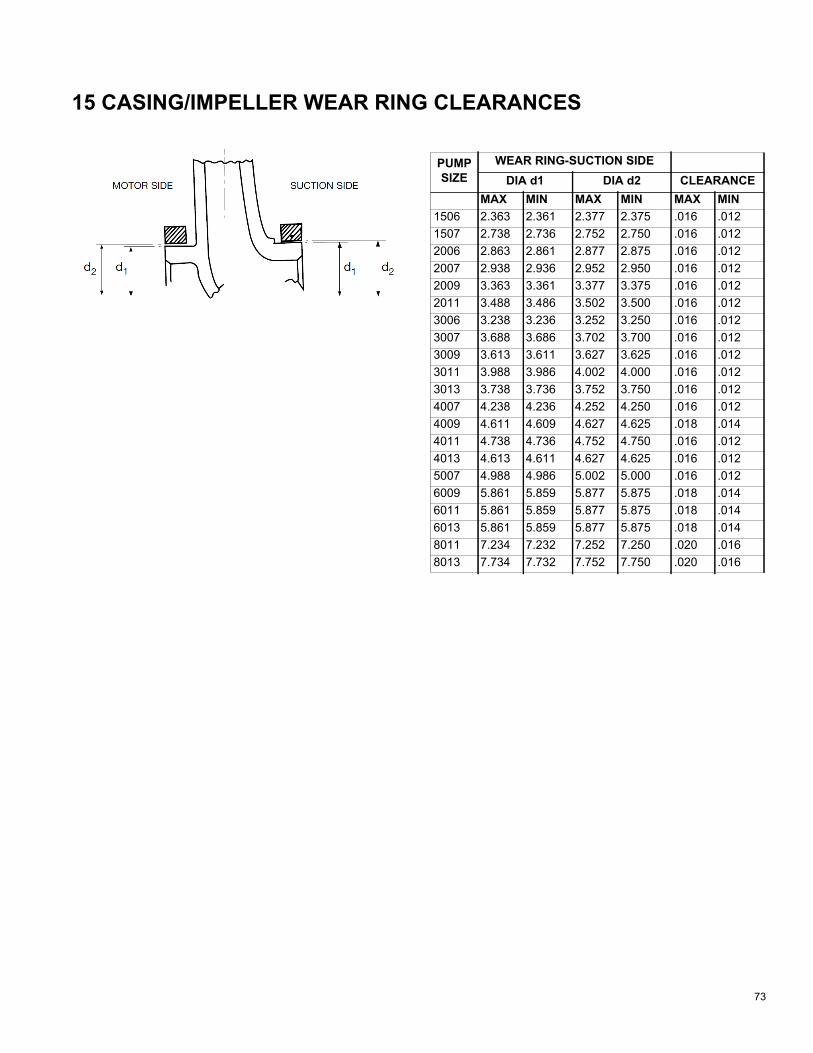
73
15 CASING/IMPELLER WEAR RING CLEARANCES
PUMP SIZE
WEAR RING-SUCTION SIDE DIA d1 DIA d2 CLEARANCE
MAX MIN MAX MIN MAX MIN1506 2.363 2.361 2.377 2.375 .016 .0121507 2.738 2.736 2.752 2.750 .016 .0122006 2.863 2.861 2.877 2.875 .016 .0122007 2.938 2.936 2.952 2.950 .016 .0122009 3.363 3.361 3.377 3.375 .016 .0122011 3.488 3.486 3.502 3.500 .016 .0123006 3.238 3.236 3.252 3.250 .016 .0123007 3.688 3.686 3.702 3.700 .016 .0123009 3.613 3.611 3.627 3.625 .016 .0123011 3.988 3.986 4.002 4.000 .016 .0123013 3.738 3.736 3.752 3.750 .016 .0124007 4.238 4.236 4.252 4.250 .016 .0124009 4.611 4.609 4.627 4.625 .018 .0144011 4.738 4.736 4.752 4.750 .016 .0124013 4.613 4.611 4.627 4.625 .016 .0125007 4.988 4.986 5.002 5.000 .016 .0126009 5.861 5.859 5.877 5.875 .018 .0146011 5.861 5.859 5.877 5.875 .018 .0146013 5.861 5.859 5.877 5.875 .018 .0148011 7.234 7.232 7.252 7.250 .020 .0168013 7.734 7.732 7.752 7.750 .020 .016

74
16 SKV PUMP PROBLEM ANALYSIS16.0.1 No Discharge1.Pump not primed.2.Speed too low.3.System head too high.4.Suction lift higher than pump is designed.5.Impeller completely clogged.6.Incorrect direction of rotation.7.Air leak in suction line.
16.0.2 Insufficient Discharge Flow1.Air leak in suction line.2.Speed too low.3.System head higher than anticipated.4.Insufficient NPSH. Suction lift too high. Check
gauges. Also check for clogged suction line orscreen.
5.Impeller partially plugged.6.Mechanical defects.
a.Worn wear ringsb.Impeller damaged.c. Incorrect direction of rotation.
16.0.3 Insufficient Discharge Pressure1.Speed too low.2.System head less than anticipated.3.Air in system.4.Mechanical defects.
a.Worn wear rings.b.Impeller damaged.c. Impeller diameter too small.d.Incorrect direction of rotation.
16.0.4 Loss of Suction1.Leak in suction line.2.Suction lift too high.3.Insufficient NPSH.4.Air in system.5.Casing gasket defective.
16.0.5 Excessive Power Consumption1.Speed too high.2.System head lower than rating.3.Specific gravity of liquid too high.4.Mechanical defects.
a.Shaft bent.b.Rotating elements bind.
c.Worn wear ring.
16.0.6 Vibration1.Air leak in suction line.2.Air in system.3.Impeller partially plugged.4.Foundation not rigid.5.Mechanical defects.
a.Damaged impeller.b.Motor bearings worn.c.Rotor out of balance.d.Shaft bent.
16.0.7 Motor Runs Hot1.Speed too high.2.Specific gravity of liquid too high.3.Mechanical defects.
a.Shaft bent.b.Rotating elements bind.c.Defective motor.d.Voltage lower than rating.

75
17 SPECIFICATIONS
17.1 Power-dependent SpecificationsTable 10: Line Power Supply 200-240 V AC
Table 11: Line Power Supply 3 x 200-240 V AC
Table 12: Line Power Supply 3 x 200-240 V AC
Table 13: Line Power Supply 3 x 380-480 V AC
Line Power Supply 200-240 V AC - Normal overload 110% for 1 minuteAdjustable frequency drive Typical Shaft Output [kW]
P1K11.1
P1K51.5
P2K22.2
P3K03
P3K73.7
IP20, IP21 max. cable cross-section (line power, motor, brake and load sharing) [mm2 (AWG)]
4, 4, 4 (12, 12, 12) (min. 0.2 (24))
IP55, IP66 max. cable cross-section (line power, motor, brake and load sharing) [mm2 (AWG)]
4, 4, 4 (12, 12, 12)
Max. cable cross-section with disconnect 6, 4, 4, (10, 12, 12)
Line Power Supply 3 x 200-240 V AC - Normal overload 110% for 1 minuteAdjustable frequency drive Typical Shaft Output [kW]
P5K55.5
P7K57.5
P11K11
P15K15
P18K18.5
IP20, IP21 max. cable cross-section (line power, motor, brake and load sharing) [mm2 (AWG)]
10, 10 (8,8-) 35,-,- (2,-,-) 35 (2) 50 (1)
IP21, IP55, IP66 max. cable cross-section (line power, motor) [mm2 (AWG)]
10, 10 (8,8-)35, 25, 25(2, 4, 4) 50 (1)
IP21, IP55, IP66 max. cable cross-section (brake, load sharing) [mm2 (AWG)]
16, 10, 16 (6, 8 ,6) 35,-,- (2,-,-) 50 (1)
Line Power Supply 3 x 200-240 V AC - Normal overload 110% for 1 minuteAdjustable frequency drive Typical Shaft Output [kW]
P22K22
P30K30
P37K37
P45K45
IP20, IP21 max. cable cross-section (line power, motor, brake and load sharing) [mm2 (AWG)]
150 (300 MCM)
IP21, IP55, IP66 max. cable cross-section (line power, motor) [mm2 (AWG)]
150 (300 MCM)
IP21, IP55, IP66 max. cable cross-section (brake, load sharing) [mm2 (AWG)]
95 (3/0)
Line Power Supply 3 x 380-480 V AC - Normal overload 110% for 1 minuteAdjustable frequency drive Typical Shaft Output [kW]
P1K11.1
P1K51.5
P2K22.2
P3K03
P4K04
P5K55.5
P7K57.5
Typical Shaft Output [HP] at 460 V 1.5 2.0 2.9 4.0 5.0 7.5 10IP20, IP21 max. cable cross-section (line power, motor, brake and load sharing) [mm2 (AWG)] 1)
4, 4, 4 (12, 12, 12)(min. 0.2 (24))
IP55, IP66 max. cable cross-section (line power, motor, brake and load sharing) [mm2 (AWG)] 1) 4, 4, 4 (12, 12, 12)
Max. cable cross-section with disconnect 6, 4, 4 (10, 12, 12)

76
Table 14: Line Power Supply 3 x 380-480 V AC
Table 15: Line Power Supply 3 x 380-480 V AC
Table 16: With brake and load sharing 95 / 4/0
Table 17: With brake and load sharing 95 / 4/0
Line Power Supply 3 x 380-480 V AC - Normal overload 110% for 1 minuteAdjustable frequency drive Typical Shaft Output [kW]
P11K11
P15K15
P18K18.5
P22K22
P30K30
Typical Shaft Output [HP] at 460 V 15 20 25 30 40 15 20 25 30 40IP20 max. cable cross-section (line power, brake, motor and load sharing) 16, 10, - (8, 8, -) 35,-,- (2,-,-) 35 (2)
IP21, IP55, IP66 max. cable cross-section (line power, motor) [mm2 (AWG)]
10, 10, 16 (6, 8, 6) 35, 25, 25 (2, 4, 4) 50 (1)
IP21, IP55, IP66 max. cable cross-section (brake, load sharing) [mm2 (AWG)]
10, 10, - (8, 8, -) 35, -, - (2, -, -) 50 (1)
Line Power Supply 3 x 380-480 V AC - Normal overload 110% for 1 minuteAdjustable frequency drive Typical Shaft Output [kW]
P37K37
P45K45
P55K55
P75K75
P90K90
Typical Shaft Output [HP] at 460 V 15 20 25 30 40 50 60 75 100 125IP20 max. cable cross-section (line power, brake, motor and load sharing) 50 (1) 150 (300 MCM)
IP21, IP55, IP66 max. cable cross-section (line power, motor) [mm2 (AWG)] 150 (300 MCM)
IP21, IP55, IP66 max. cable cross-section (brake, load sharing) [mm2 (AWG)] 95 (3/0)
Line Power Supply 3 x 525-600 V AC - Normal overload 110% for 1 minuteSize: P1K1 P1K5 P2K2 P3K0 P3K7 PK40 P5K5 P7K5 P11KTypical Shaft Output [kW] 1.1 1.5 2.2 3 3.7 4 5.5 7.5 11IP20 max. cable cross-section (line power, motor, brake and load sharing) [mm2]/[AWG]
4, 4, 4 (12, 12, 12)(min. 0.2 (24))
IP55, IP66 max. cable cross-section (line power, motor, brake and load sharing) [mm2]/[AWG]
4, 4, 4 (12, 12, 12)(min. 0.2 (24))
Max. cable cross-section with disconnect 6, 4, 4 (12, 12, 12)
Line Power Supply 3 x 525-600 V AC - Normal overload 110% for 1 minuteSize: P15K P18K P22K P30K P37K P45K P55K P75K P90KTypical Shaft Output [kW] 15 18.5 22 30 37 45 55 75 90 IP20 max. cable cross-section (line power, motor, brake and load sharing) [mm2]/[AWG]IP55, IP66 max. cable cross-section (line power, motor, brake and load sharing) [mm2]/[AWG]Max. cable cross-section with disconnect
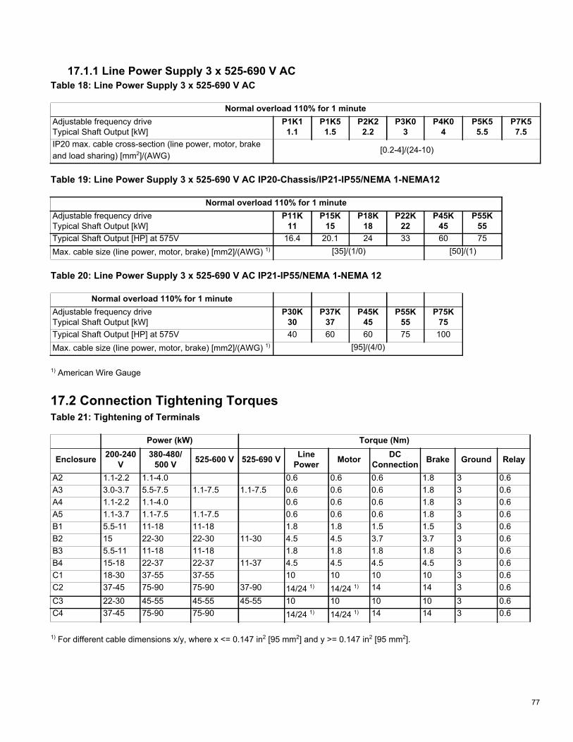
77
17.1.1 Line Power Supply 3 x 525-690 V ACTable 18: Line Power Supply 3 x 525-690 V AC
Table 19: Line Power Supply 3 x 525-690 V AC IP20-Chassis/IP21-IP55/NEMA 1-NEMA12
Table 20: Line Power Supply 3 x 525-690 V AC IP21-IP55/NEMA 1-NEMA 12
1) American Wire Gauge
17.2 Connection Tightening TorquesTable 21: Tightening of Terminals
1) For different cable dimensions x/y, where x <= 0.147 in2 [95 mm2] and y >= 0.147 in2 [95 mm2].
Normal overload 110% for 1 minuteAdjustable frequency drive Typical Shaft Output [kW]
P1K11.1
P1K51.5
P2K22.2
P3K03
P4K04
P5K55.5
P7K57.5
IP20 max. cable cross-section (line power, motor, brake and load sharing) [mm2]/(AWG)
[0.2-4]/(24-10)
Normal overload 110% for 1 minuteAdjustable frequency drive Typical Shaft Output [kW]
P11K11
P15K15
P18K18
P22K22
P45K45
P55K55
Typical Shaft Output [HP] at 575V 16.4 20.1 24 33 60 75Max. cable size (line power, motor, brake) [mm2]/(AWG) 1) [35]/(1/0) [50]/(1)
Normal overload 110% for 1 minuteAdjustable frequency drive Typical Shaft Output [kW]
P30K30
P37K37
P45K45
P55K55
P75K75
Typical Shaft Output [HP] at 575V 40 60 60 75 100Max. cable size (line power, motor, brake) [mm2]/(AWG) 1) [95]/(4/0)
Power (kW) Torque (Nm)
Enclosure 200-240V
380-480/500 V 525-600 V 525-690 V Line
Power Motor DC Connection Brake Ground Relay
A2 1.1-2.2 1.1-4.0 0.6 0.6 0.6 1.8 3 0.6A3 3.0-3.7 5.5-7.5 1.1-7.5 1.1-7.5 0.6 0.6 0.6 1.8 3 0.6A4 1.1-2.2 1.1-4.0 0.6 0.6 0.6 1.8 3 0.6A5 1.1-3.7 1.1-7.5 1.1-7.5 0.6 0.6 0.6 1.8 3 0.6B1 5.5-11 11-18 11-18 1.8 1.8 1.5 1.5 3 0.6B2 15 22-30 22-30 11-30 4.5 4.5 3.7 3.7 3 0.6B3 5.5-11 11-18 11-18 1.8 1.8 1.8 1.8 3 0.6B4 15-18 22-37 22-37 11-37 4.5 4.5 4.5 4.5 3 0.6C1 18-30 37-55 37-55 10 10 10 10 3 0.6C2 37-45 75-90 75-90 37-90 14/24 1) 14/24 1) 14 14 3 0.6C3 22-30 45-55 45-55 45-55 10 10 10 10 3 0.6C4 37-45 75-90 75-90 14/24 1) 14/24 1) 14 14 3 0.6

78
APPENDIX A: SET-UP FOR STANDBY PUMP ALTERNATIONThis section describes how to alternate Taco SKV pump units based on elapsed time and how to configure the standby pump to energize in the event that the duty pump fails.
A.1 OverviewTwo identical drives are used; one installed on each pump. One drive is configured as the “lead” drive and the other as the “standby” drive, but both drives participate equally in the alternation. The “lead” drive is the drive that controls the alternation process. If one drive enters an alarm condition, the other automatically assumes operation. Alternation attempts do not occur when one drive is in alarm.
This system requires one set of dry contacts for start/stop. Twenty-four VDC control voltage from both drives is wired to the lead drive’s relay 1. If the lead drive’s control circuitry is working, it supplies power. If the lead drive cannot provide control voltage, the standby drive automatically assumes control.
Figure A-1: Wiring for 2x0 Pump Alternation
No external monitoring is needed. Pump alternation is controlled by the active set-up of each drive. The active set-up is controlled by the lead drive.
• Under normal conditions, the lead drivechanges its active set-up based on the time delay specified in timer 0 byparameter setting 13–20.0.
• When the lead drive is operating normally in set-up 1, its digital output 29 is high. This state puts the standby driveinto set-up 2.
• When the lead drive is operating normally in set-up 2, its digital output 29 is low. This state puts the standby driveinto set-up 1.
• If the lead drive encounters an alarm condition or loses power, its digital output 29 is low. This state puts thestandby drive into set-up 1, allowing it to take over operation.
• If the standby drive encounters an alarm condition or loses power, its digital output 27 is low. This condition causesthe lead drive to move into set-up 1, allowing it to take over operation.
12+24V
13+24V
18D IN
19D IN
27D IN
29D IN
32D IN
33D IN
20COM
I/O Digital01
COM
Relay 102NO
03NCDrive 1
12+24V
13+24V
18D IN
19D IN
27D IN
29D IN
32D IN
33D IN
20COM
I/O Digital
Drive 2

79
During system commissioning and other situations, the user may want to force pump alternation rather than rely on the setting in parameter 13-20.0.
• Logic rule 1 allows the user to override the timer bypressing the [ok] and [>] keys on the keypad (localcontrol panel) simultaneously.
• Timer 1 offers “anti–bounce” protection for this keycombination. After this combination of keys ispressed, the drive ignores any instance of the samecombination again for two seconds.
A.2 SettingsSettings to operate the standby pump alternation have been programmed into the My Personal Menu. Follow this procedure to enable the drive's standby pump alter-nation capabilities.
1.Press the [Quick Menus] button.
2.Press the [OK] button to enter “My PersonalMenu.”
3.Scroll down to Parameter 13-20 SL Con-troller Time and press [OK].
4.(Set the amount of time between pump alterna-tions. Factory default is 24 hours. Maximum value is 99 hours.a.Parameter 13-20 = SL Controller Time.
5.Press [OK].
6.Scroll down to Parameter 0-10 Active Set-up and press [OK].
7.Change “Active Set-up 1” to “Multi Set-up”.a.Parameter 0-10 = Active Set-up.
8.Press [OK].
9.Repeat this procedure on the Standby Drive.
A.2.1 Check Alternation1.Ensure the lead and standby pumps are connected
per wiring diagram in Figure A-1 above.2.On the Lead drive (Drive A), Press the [Status] but-
ton to get back to the main screen.
3.The Lead drive (Drive A) should display in the upper right hand corner of the screen (Set-up 1).
4.On the Standby drive (Drive B), Press the [Status]button to get back to the main screen.

80
5.The Standby drive (Drive B) should display in the upper right hand corner of the screen (Set-up2).
6.If Drive B remains in Set-up 1 , check the fol-lowing:a.Check that wire connections comply with
Figure A-1.b.Check that both Drives’ active set-ups are set to
“Multi Set-up” per Section A.2 ”Settings”.7.To test alternation, Press [OK] and [Right Arrow] at
the same time.
8.Observe the two drives swap setups.a.Drive A switches to Set-up 2 , becoming the
Standby Drive.b.Drive B switches to Set-up 1 , becoming the
Lead Drive.9.Repeate step 7 as desired.10.The pumps are now ready for alternation.

81
A.3 ParametersTable 22: Lead and Lag Drive Parameters
Parameter Number Parameter NameParameter Value
Set-up 1 Set-up 20–01 Language [22] English US [22] 0–03 Regional settings [1] North America [1] North America0–10 Active set-up [9] Multi set-up [9] Multi set-up0–11 Programming set-up [1] Set-up 1 [2] Set-up 20–12 This set–up linked to [0] Not linked [1] Set-up 15–01 Terminal 27 mode [1] Output [1] Output5–02 Terminal 29 mode [1] Output [1] Output5–10 Terminal 18 digital input [8] Start [0] No operation5–11 Terminal 19 digital input [0] No operation [0] No operation5–12 Terminal 27 digital input [0] No operation [0] No operation5–13 Terminal 29 digital input Jog Jog5–14 Terminal 32 digital input [0] No operation [0] No operation5–15 Terminal 33 digital input [23] Set-up select bit 0 [23] Set-up select bit 05–19 Terminal 37 Safe Stop Safe Stop Alarm Safe Stop Alarm5–30 Terminal 27 digital output [160] No alarm [160] No alarm5–31 Terminal 29 digital output [160] No alarm [0] No operation5–40 Relay 1 [1] Control ready [1] Control ready5–40.0 Function Relay [1] Control ready [1] Control ready5–40.1 Function Relay Running Running
State controller start and stop events 13–00 SL controller mode [1] on [1] on13–01 Start event [37] Digital input di32 [37] Digital input di3213–02 Stop event [26] Logic rule 0 [26] Logic rule 013–20.0 SL controller timer 0 024:00:00.000 024:00:00.00013–20.1 SL controller timer 1 000:00:02.000 000:00:02.000
Logic rules 13–40.0 Logic rule boolean 1 [37] Digital input di32 [37] Digital input di3213–40.1 Logic rule boolean 1 [43] ok key [43] ok key13–41.0 Logic rule operator 1 [5] not and [5] not and13–41.1 Logic rule operator 1 [1] and [1] and13–42.0 Logic rule boolean 2 [1] true [1] true13–42.1 Logic rule boolean 2 [46] Right key [46] Right key13–43.1 Logic rule operator 2 [2] or [2] or13–44.1 Logic rule boolean 3 [30] SL time–out 0 [30] SL time–out 0
States13–51.0 SL controller event [1] true [1] true13–51.1 SL controller event [31] SL time–out 1 [31] SL time–out 113–51.2 SL controller event [27] Logic rule 1 [27] Logic rule 113–51.3 SL controller event [1] true [1] true13–51.4 SL controller event [31] sl time–out 1 [31] sl time–out 113–51.5 SL controller event [27] Logic rule 1 [27] Logic rule 113–52.0 SL controller action [30] Start timer 1 [30] Start timer 113–52.1 SL controller action [29] Start timer 0 [29] Start timer 0

82
13–52.2 SL controller action [3] Select set-up 2 [3] Select set-up 213–52.3 SL controller action [30] Start timer 1 [30] Start timer 113–52.4 SL controller action [29] Start timer 0 [29] Start timer 013–52.5 SL controller action [2] Select set-up 1 [2] Select set-up 1
Parameter Number Parameter NameParameter Value
Set-up 1 Set-up 2
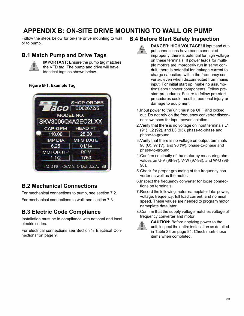
83
APPENDIX B: ON-SITE DRIVE MOUNTING TO WALL OR PUMPFollow the steps below for on-site drive mounting to wall or to pump.
B.1 Match Pump and Drive TagsIMPORTANT: Ensure the pump tag matches the VFD tag. The pump and drive will have identical tags as shown below.
Figure B-1: Example Tag
B.2 Mechanical ConnectionsFor mechanical connections to pump, see section 7.2.
For mechanical connections to wall, see section 7.3.
B.3 Electric Code ComplianceInstallation must be in compliance with national and local electric codes.
For electrical connections see Section “8 Electrical Con-nections” on page 9.
B.4 Before Start Safety InspectionDANGER: HIGH VOLTAGE! If input and out-put connections have been connected improperly, there is potential for high voltage on these terminals. If power leads for multi-ple motors are improperly run in same con-duit, there is potential for leakage current to charge capacitors within the frequency con-verter, even when disconnected from mains input. For initial start up, make no assump-tions about power components. Follow pre-start procedures. Failure to follow pre-start procedures could result in personal injury or damage to equipment.
1.Input power to the unit must be OFF and lockedout. Do not rely on the frequency converter discon-nect switches for input power isolation.
2.Verify that there is no voltage on input terminals L1(91), L2 (92), and L3 (93), phase-to-phase andphase-to-ground.
3.Verify that there is no voltage on output terminals96 (U), 97 (V), and 98 (W), phase-to-phase andphase-to-ground.
4.Confirm continuity of the motor by measuring ohmvalues on U-V (96-97), V-W (97-98), and W-U (98-96).
5.Check for proper grounding of the frequency con-verter as well as the motor.
6.Inspect the frequency converter for loose connec-tions on terminals.
7.Record the following motor-nameplate data: power,voltage, frequency, full load current, and nominalspeed. These values are needed to program motornameplate data later.
8.Confirm that the supply voltage matches voltage offrequency converter and motor.
CAUTION: Before applying power to the unit, inspect the entire installation as detailed in Table 23 on page 84. Check mark those items when completed.

84
Table 23: Inspection Checklist
B.5 Applying Power to the Frequency ConverterDANGER: HIGH VOLTAGE! Frequency converters contain high voltage when connected to AC mains. Installation, start-up and maintenance should be performed by qualified personnel only. Failure to comply could result in death or serious injury.
Inspect for Description Check?Auxiliary equipment – Look for auxiliary equipment, switches, disconnects, or input fuses/cir-
cuit breakers that may reside on the input power side of the frequencyconverter or output side to the motor. Ensure that they are ready for fullspeed operation.
– Check function and installation of any sensors used for feedback to thefrequency converter.
– Remove power factor correction caps on motor(s), if present.Cable routing – Ensure that input power, motor wiring, and control wiring are separated
or in three separate metallic conduits for high frequency noise isolation.Control wiring – Check for broken or damaged wires and loose connections.
– Check that control wiring is isolated from power and motor wiring fornoise immunity.
– Check the voltage source of the signals, if necessary.– The use of shielded cable or twisted pair is recommended. Ensure that
the shield is terminated correctly.Cooling clearance – Measure that top and bottom clearance is adequate to ensure proper air
flow for cooling.EMC considerations – Check for proper installation regarding electromagnetic compatibility.Environmental considerations – See equipment label for the maximum ambient operating temperature
limits.– Humidity levels must be 5-95% non-condensing.
Fusing and circuit breakers – Check for proper fusing or circuit breakers.– Check that all fuses are inserted firmly and in operational condition and
that all circuit breakers are in the open position.(grounding) – The unit requires an earth wire(ground wire) from its chassis to the build-
ing earth (ground).– Check for good earth connections(ground connections) that are tight
and free of oxidation.– Earthing (Grounding) to conduit or mounting the back panel to a metal
surface is not a suitable earth (ground).Input and output power wiring – Check for loose connections.
– Check that motor and mains are in separate conduit or separatedscreened cables.
Panel interior – Inspect that the unit interior is free of dirt, metal chips, moisture, and cor-rosion.
Switches – Ensure that all switch and disconnect settings are in the proper posi-tions.
Vibration – Check that the unit is mounted solidly or that shock mounts are used, asnecessary.
– Check for an unusual amount of vibration.

85
WARNING: UNINTENDED START! When the frequency converter is connected to AC mains, the motor may start at any time. The frequency converter, motor, and any driven equipment must be in operational readiness. Failure to comply could result in death, seri-ous injury, equipment, or property damage.
1.Confirm the input voltage is balanced within 3%. Ifnot, correct input voltage imbalance before pro-ceeding. Repeat this procedure after the voltagecorrection.
2.Ensure that optional equipment wiring, if present,matches the installation application.
3.Ensure that all operator devices are in the OFFposition. Panel doors should be closed or covermounted.
4.Apply power to the unit. DO NOT start the fre-quency converter at this time. For units with a dis-connect switch, turn to the ON position to applypower to the frequency converter.
NOTE: If the status line at the bottom of the LCP reads “AUTO REMOTE COASTING” or “Alarm 60 External Interlock” is displayed, this indicates that the unit is ready to operate but is missing an input signal on terminal 27.
B.6 Run Automatic Motor AdaptationAutomatic motor adaptation (AMA) is a test procedure that measures the electrical characteristics of the motor to optimize compatibility between the frequency con-verter and the motor.
• The frequency converter builds a mathematicalmodel of the motor for regulating output motor cur-rent. The procedure also tests the input phase bal-ance of electrical power. It compares the motorcharacteristics with the data entered in parameters 1-20 to 1-25.
• It does not cause the motor to run or harm to themotor. Some motors may be unable to run the com-plete version of the test. In that case, select Enablereduced AMA.
• If an output filter is connected to the motor, selectEnable reduced AMA.
• Run this procedure on a cold motor for best results.
NOTE: The AMA algorithm does not work when using PM motors.
NOTE: AMA has already been completed by Taco on all pump-mounted VFDs. You will only need to run AMA if the wire/motor lead is different from the one supplied by Taco.
To run AMA:
1.Press [Main Menu] to access parameters.2.Scroll to parameter group 1-** Load and Motor.3.Press [OK].4.Scroll to parameter group 1-2* Motor Data.5.Press [OK].6.Scroll to 1-29 Automatic Motor Adaptation (AMA).7.Press [OK].8.Select Enable complete AMA.9.Press [OK].10.Follow on-screen instructions.11.The test runs automatically and indicates when it
is complete.
B.7 Increase Warning Current LimitIncrease warning current limit in parameter 4-51 Warning Current High to the current specified on motor name-plate.
B.8 Check Motor RotationBefore running the frequency converter, check the motor rotation. The motor will run briefly at 5Hz or the minimum frequency set in 4-12 Motor Speed Low Limit [Hz].
1.Press [Quick Menu].2.Scroll to Q2 Quick Set-up.3.Press [OK].4.Scroll to 1-28 Motor Rotation Check.5.Press [OK].6.Scroll to Enable.7.The following text appears: “Note! Motor may run in
wrong direction.”8.Press [OK].9.Follow the on-screen instructions.
To change the direction of rotation, remove power to the frequency converter and wait for power to discharge. Reverse the connection of any two of the three motor cables on the motor or frequency converter side of the connection.
B.9 Start-up ProcedureFollow Start-up procedure shown in “11 Start-Up Proce-dure” on page 37.
12.Verify that parameters 1-25, 1-39 and 1-40correspond to values on the motor nameplate following the AMA procedure.

Taco, Inc. (Taco) will repair or replace without charge (at the company's option) any product or part which is proven defective under normal use within one (1) year from the date of start-up or one (1) year and six (6) months from date of shipment (whichever occurs first).
In order to obtain service under this warranty, it is the responsibility of the purchaser to promptly notify the local Taco stocking distribu-tor or Taco in writing and promptly deliver the subject product or part, delivery prepaid, to the stocking distributor. For assistance on war-ranty returns, the purchaser may either contact the local Taco stocking distributor or Taco. If the subject product or part contains no defect as covered in this warranty, the purchaser will be billed for parts and labor charges in effect at time of factory examination and repair.
Any Taco product or part not installed or oper-ated in conformity with Taco instructions or which has been subject to accident, disaster, neglect, misuse, misapplication, inadequate operating environment, repair, attempted repair, modification or alteration, or other abuse, will not be covered by this warranty.
Taco products are not intended for use to sup-port fire suppression systems, life support sys-tems, critical care applications, commercial aviation, nuclear facilities or any other applica-tions where product failure could lead to injury to person, loss of life, or catastrophic property damage and should not be sold for such pur-poses.
If in doubt as to whether a particular product is suitable for use with a Taco product or part, or for any application restrictions, consult the applicable Taco instruction sheets or in the U.S. contact Taco at 401-942-8000 and in Canada contact Taco (Canada) Limited at 905-564-9422.
Taco reserves the right to provide replacement products and parts which are substantially simi-lar in design and functionally equivalent to the defective product or part. Taco reserves the right to make changes in details of design, con-struction, or arrangement of materials of its products without notification.
TACO OFFERS THIS WARRANTY IN LIEU OF ALL OTHER EXPRESS WARRANTIES. ANY WARRANTY IMPLIED BY LAW
INCLUDING WARRANTIES OF MERCHANT-ABILITY OR FITNESS IS IN EFFECT ONLY FOR THE DURATION OF THE EXPRESS WARRANTY SET FORTH IN THE FIRST PARAGRAPH ABOVE.
THE ABOVE WARRANTIES ARE IN LIEU OF ALL OTHER WARRANTIES, EXPRESS OR STATUTORY, OR ANY OTHER WARRANTY OBLIGATION ON THE PART OF TES.
TACO WILL NOT BE LIABLE FOR ANY SPE-CIAL, INCIDENTAL, INDIRECT OR CONSE-QUENTIAL DAMAGES RESULTING FROM THE USE OF ITS PRODUCTS OR ANY INCI-DENTAL COSTS OF REMOVING OR REPLACING DEFECTIVE PRODUCTS.
This warranty gives the purchaser specific rights, and the purchaser may have other rights which vary from state to state. Some states do not allow limitations on how long an implied warranty lasts or on the exclusion of incidental or consequential damages, so these limitations or exclusions may not apply to you.
LIMITED WARRANTY STATEMENT