sky pi user manual - sky support bank 733 0170133 25 - btw: be 0407 249 055 - hra 185.015 website: ...
TRANSCRIPT

N.V. SKY CLIMBER EUROPE S.A. – Nijverheidsstraat 23 - 2570 Duffel - Belgium Email: [email protected] - Tel: +32 (0)3 887 81 20 - Fax: +32 (0)3 887 09 94
KBC Bank 733 0170133 25 - BTW: BE 0407 249 055 - HRA 185.015
Website: http://www.skyclimber.com
SKY CLIMBER LLC - 1501 Rock Mountain Blvd. - Stone Mountain - Georgia 30083 - U.S.A
Email: [email protected] - Tel: +1 770 939 7705 - Fax: +1 770 493 7392
Page 1 of 16 Sky Climber ref.: 34UME001 Mod.: A Date: 28/10/2009
SKY PI USER MANUAL
All persons operating this equipment must read and completely understand this manual.
Any operation in violation of these instructions is at the operator’s own risk.
Keep this manual with the equipment at all times.

N.V. SKY CLIMBER EUROPE S.A. – Nijverheidsstraat 23 - 2570 Duffel - Belgium Email: [email protected] - Tel: +32 (0)3 887 81 20 - Fax: +32 (0)3 887 09 94
KBC Bank 733 0170133 25 - BTW: BE 0407 249 055 - HRA 185.015
Website: http://www.skyclimber.com
SKY CLIMBER LLC - 1501 Rock Mountain Blvd. - Stone Mountain - Georgia 30083 - U.S.A
Email: [email protected] - Tel: +1 770 939 7705 - Fax: +1 770 493 7392
Page 2 of 16 Sky Climber ref.: 34UME001 Mod.: A Date: 28/10/2009
Table of contents
1. Purpose, limitations and condition of use. ......................................................................................... 3
2. General view of the basket ................................................................................................................ 3
3. Nameplate basket.............................................................................................................................. 5
4. Basket specifications ......................................................................................................................... 5
4.1. Basket ................................................................................................................................................ 5
4.2. Hoist: Compact S............................................................................................................................... 5
4.3. Safety device: Sky grip ...................................................................................................................... 5
5. Central control box............................................................................................................................. 6
5.1. installation of the CCB ....................................................................................................................... 6
5.2. Maintenance of the CCB.................................................................................................................... 7
6. Movements of basket, control functions. ........................................................................................... 8
7. SKY GRIP particularities.................................................................................................................... 9
8. No power control descent .................................................................................................................. 9
9. Overload/Underload safety device .................................................................................................. 10
10. Top limit and ultimate top limit ......................................................................................................... 11
11. Bottom limit ...................................................................................................................................... 12
12. Twin drum wire winders ................................................................................................................... 13
12.1. Installation of the twin drum wire winders........................................................................................ 13
12.2. Maintenance of the twin drum wire winders .................................................................................... 14
13. Additional Safety guidelines ............................................................................................................ 15
14. Hoist................................................................................................................................................. 15
15. Daily Check list ................................................................................................................................ 15
16. Maintenance of the BMU ................................................................................................................. 15
16.1. Routine maintenance....................................................................................................................... 15
16.2. Annual maintenance or every 50 running hours:............................................................................. 15
Appendix
A. SKY CLIMBER general users manual V2.0 .................................................................................... 15
B. SKY CLIMBER SKY GRIP assembly manual ................................................................................. 15
C. SKY CLIMBER SKY GRIP users manual........................................................................................ 15
D. SKY CLIMBER Assembly manual compact S................................................................................. 15
E. SKY CLIMBER Wiring Diagram - Central Control Unit.................................................................... 15
F. SKY CLIMBER Assembly manual safety devices for Compact / CX .............................................. 15

N.V. SKY CLIMBER EUROPE S.A. – Nijverheidsstraat 23 - 2570 Duffel - Belgium Email: [email protected] - Tel: +32 (0)3 887 81 20 - Fax: +32 (0)3 887 09 94
KBC Bank 733 0170133 25 - BTW: BE 0407 249 055 - HRA 185.015
Website: http://www.skyclimber.com
SKY CLIMBER LLC - 1501 Rock Mountain Blvd. - Stone Mountain - Georgia 30083 - U.S.A
Email: [email protected] - Tel: +1 770 939 7705 - Fax: +1 770 493 7392
Page 3 of 16 Sky Climber ref.: 34UME001 Mod.: A Date: 28/10/2009
1. Purpose, limitations and condition of use. This SAE (Suspended Access Equipment) is a BMU (Building maintenance Unit) to be permanently installed and dedicated to a specific building or structure and to be used for planned for routine inspection, cleaning and maintenance of the particular building. The power for the Permanent Installation ( PI ) is provided with a power supply cable. The power in the PI is fused and has an earth leakage detection of 30mA. Wind conditions: Max 12m/s – Rated load: Max 240 kg
2. General view of the basket
Figure 1: General view of the PI

N.V. SKY CLIMBER EUROPE S.A. – Nijverheidsstraat 23 - 2570 Duffel - Belgium Email: [email protected] - Tel: +32 (0)3 887 81 20 - Fax: +32 (0)3 887 09 94
KBC Bank 733 0170133 25 - BTW: BE 0407 249 055 - HRA 185.015
Website: http://www.skyclimber.com
SKY CLIMBER LLC - 1501 Rock Mountain Blvd. - Stone Mountain - Georgia 30083 - U.S.A
Email: [email protected] - Tel: +1 770 939 7705 - Fax: +1 770 493 7392
Page 4 of 16 Sky Climber ref.: 34UME001 Mod.: A Date: 28/10/2009
Figure 2: General dimensions and description of main parts of the PI
1 Safety rope 11 Overload/underload safety device
2 Suspension rope 12 Eye bolt
3 Sky Grip, See Sky Grip Manual, appendix C 13 Electric supply cable collection bin
4 Compact Hoist, see appendix D 14 Twin drum Wire Winder
5 Wire winder protection 15 Castor wheel
6 Central Control Box 16 Striker plate
7 Cradle 17 Handwheel
8 Bottom limit trip bar 18 No power descent lever
9 Top limit switch and ultimate top limit switch 19 Foot step
10 Steel Stirrup 20 Wall roller
N.V. SKY CLIMBER EUROPE S.A. – Nijverheidsstraat 23 - 2570 Duffel - Belgium Email: [email protected] - Tel: +32 (0)3 887 81 20 - Fax: +32 (0)3 887 09 94
KBC Bank 733 0170133 25 - BTW: BE 0407 249 055 - HRA 185.015
Website: http://www.skyclimber.com
SKY CLIMBER LLC - 1501 Rock Mountain Blvd. - Stone Mountain - Georgia 30083 - U.S.A
Email: [email protected] - Tel: +1 770 939 7705 - Fax: +1 770 493 7392
Page 5 of 16 Sky Climber ref.: 34UME001 Mod.: A Date: 28/10/2009
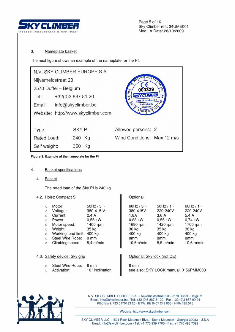
3. Nameplate basket The next figure shows an example of the nameplate for the PI. Figure 3: Example of the nameplate for the PI
4. Basket specifications
4.1. Basket
The rated load of the Sky PI is 240 kg
4.2. Hoist: Compact S Optional
o Motor: 50Hz / 3 ~ 60Hz / 3 ~ 50Hz / 1~ 60Hz / 1~ o Voltage: 380-415 V 380-415V 220-240V 220-240V o Current: 2,4 A 1,8A 3,6 A 5,4 A o Power: 0,55 kW 0,88 kW 0,55 kW 0,74 kW o Motor speed: 1400 rpm 1690 rpm 1420 rpm 1700 rpm o Weight: 35 kg 36 kg 35 kg 36 kg o Working load limit: 400 kg 400 kg 400 kg 400 kg o Steel Wire Rope: 8 mm 8mm 8mm 8mm o Climbing speed: 8,4 m/min 10,6m/min 8,5 m/min 10,6 m/min
4.3. Safety device: Sky grip Optional: Sky lock (not CE)
o Steel Wire Rope: 8 mm 8 mm o Activation: 10° inclination see also: SKY LOCK manual � 56PMM003

N.V. SKY CLIMBER EUROPE S.A. – Nijverheidsstraat 23 - 2570 Duffel - Belgium Email: [email protected] - Tel: +32 (0)3 887 81 20 - Fax: +32 (0)3 887 09 94
KBC Bank 733 0170133 25 - BTW: BE 0407 249 055 - HRA 185.015
Website: http://www.skyclimber.com
SKY CLIMBER LLC - 1501 Rock Mountain Blvd. - Stone Mountain - Georgia 30083 - U.S.A
Email: [email protected] - Tel: +1 770 939 7705 - Fax: +1 770 493 7392
Page 6 of 16 Sky Climber ref.: 34UME001 Mod.: A Date: 28/10/2009
5. Central control box
o Supply voltage: 400V / 50Hz / 3 phase o Control voltage: 24V CCB Optional: o Supply voltage: 220V – 380V / 50Hz – 60Hz / 3 phase – 1 phase o Control voltage: 24V – (220V not CE) o Trolleys control
5.1. installation of the CCB The installation needs to be done by a competent electrician.
o The central control box is installed in the middle of the PI at the factory. o Recheck that ale leads are positioned so that leads cannot be damage by normal use. Specially
take attention close to steel wire rope and wire winder. o Connect the supply cable and make sure that the supply cable is in the compartment next to the
central control box. o Switch the emergency push button on top of the control box OFF by turning it (rotate red button to
the right). o Check that the general contactor is activated, if not you must do the following:
� Check that the plugs of the hoists are connected � Check the emergency button, you can reset it by turning it. � Check the plugs of the UTL and OL/UL device � Check if the phase sequence is wrong: switch two phases in your power supply.
o Test Emergency Push Button: Operate the basket in both directions, make sure the basket goes
UP when pushing the "UP" button, and hit the emergency push button in each direction. The PI stops moving. To regain movement you need to reset the emergency push button by turning it.
o Test Selector Switch: The Selector Switch has 3 positions. It operates the first hoist (I), both hoists (I+II) or the second hoist (II). Try out each position and check the reaction.
o Test anti-tilting device: when suspended operate one side with the selector switch and tilt the PI 5° at the left side, when operating both of the hoists "UP": the 'left' hoist should stop moving up. Repeat test for the opposite side and also in the "DOWN" mode.
o Anti-Tilting Device. The central control box is also fitted with an ANTI TILTING DEVICE. The purpose of this device is to avoid the cradle going out of level. For instance when the cradle is being lowered it if tilts by more than 5 degrees the lower hoist will stop allowing the other which continues to operate and return the cradle to its correct position. When the cradle is being operated in the up direction if it goes out of level by more than 5 degrees the upper hoist will stop allowing the lower hoist to continue operating and return the cradle to its correct position. It is therefore important to have the central control box mounted correctly on the cradle. If this has not been done right, the anti-tilting device will not work properly.
o The CCB is now ready to use. The wiring diagram of central control box is included inside and should always remain there.
N.V. SKY CLIMBER EUROPE S.A. – Nijverheidsstraat 23 - 2570 Duffel - Belgium Email: [email protected] - Tel: +32 (0)3 887 81 20 - Fax: +32 (0)3 887 09 94
KBC Bank 733 0170133 25 - BTW: BE 0407 249 055 - HRA 185.015
Website: http://www.skyclimber.com
SKY CLIMBER LLC - 1501 Rock Mountain Blvd. - Stone Mountain - Georgia 30083 - U.S.A
Email: [email protected] - Tel: +1 770 939 7705 - Fax: +1 770 493 7392
Page 7 of 16 Sky Climber ref.: 34UME001 Mod.: A Date: 28/10/2009
After everything has been connected and tested correctly by a competent person, the central control box must be used as follows: RAISING AND LOWERING On the front panel there are two push buttons: a button to raise and a button to lower the basket. For instance, to lower the basket one has to push the down button until the basket reaches the required height. The buttons may never be blocked in an active (pushed inwards) position. The selector switch has to point to the middle option: I+II. Both hoists will then be operated at the same time. EMERGENCY SITUATION The emergency push button on top of the control box is useful to switch the complete installation off in case of an EMERGENCY. The emergency push button can be reset by turning it. On the front panel the selector switch can be used to operate either the left or right hoist only. When dereeving the hoist the selector switch must be turned to I (first hoist) or II (second hoist) depending on the hoist being dereeved. Use the push button (DOWN) to activate the dereeving. 5.2. Maintenance of the CCB PERIODIC INSPECTIONS: Only a competent person may carry out the maintenance.
o Pull out the main power supply before touching the wiring. The wiring up to the emergency button can still be under tension.
o Each central control box and hoist is delivered with a wiring diagram (in a plastic bag) (appendix E). Preserve this in the central control box and hoist in order to avoid needless searching.
o The box: check on water penetration and possible corrosion on the contacts. o The emergency push button: check if the screws connecting the emergency button on the box are
still fixed. o The labels: check if all labels and indications are present and legible. o The cables: check if there are no external damages on the outer jacket and/or isolation in order to
avoid short-circuit.

N.V. SKY CLIMBER EUROPE S.A. – Nijverheidsstraat 23 - 2570 Duffel - Belgium Email: [email protected] - Tel: +32 (0)3 887 81 20 - Fax: +32 (0)3 887 09 94
KBC Bank 733 0170133 25 - BTW: BE 0407 249 055 - HRA 185.015
Website: http://www.skyclimber.com
SKY CLIMBER LLC - 1501 Rock Mountain Blvd. - Stone Mountain - Georgia 30083 - U.S.A
Email: [email protected] - Tel: +1 770 939 7705 - Fax: +1 770 493 7392
Page 8 of 16 Sky Climber ref.: 34UME001 Mod.: A Date: 28/10/2009
6. Movements of basket, control functions. In the next figure all the movements of the basket are indicated with the arrows. So there can be moved UP and DOWN.
Figure 4: Movements of the basket and front view of central control box CCB Functions:
- Main power switch - To stop the basket in case of emergency: Press the emergency button - To go UP: Push the up arrow button - To go DOWN: Push the down arrow button - To power the left hoist: turn the selector switch left - To power the right hoist: turn the selector switch right - Bottom limit override: to travel downwards while the trip bar is activated - Test button: to test if the safety circuit still works (signal by buzzer) - Buzzer: sounds when the PI goes in to OL/UL, when the UTL is switched, or when there is a plug
disconnected - Inside: hour counter Important instructions: - Make sure during travelling that there are no obstacles. - Constantly take special attention at the supply cable! Check that the supply cable is always free
hanging and does not hook anywhere, also underneath the basket while going down. - When the basket is stationary to perform tasks the main power switch should be OFF. The basket is electrically automatic levelled at 5°. No separate control of the hoist is needed In order to be able to reeve the ropes into the wire winders, the hoists can be controlled independently. Here for turn the selector switch left or right to control the corresponding hoist. If the SKY GRIPS safety device blocks the down movement of the lower hoist. Just push to UP button for a while, the basket will level automatically and the SKY GRIP will be reset automatically. The hour counter indicates the downward movement only. For maintenance purposes multiply the hours on the counter with 2 to have the total runtime for the hoists.

N.V. SKY CLIMBER EUROPE S.A. – Nijverheidsstraat 23 - 2570 Duffel - Belgium Email: [email protected] - Tel: +32 (0)3 887 81 20 - Fax: +32 (0)3 887 09 94
KBC Bank 733 0170133 25 - BTW: BE 0407 249 055 - HRA 185.015
Website: http://www.skyclimber.com
SKY CLIMBER LLC - 1501 Rock Mountain Blvd. - Stone Mountain - Georgia 30083 - U.S.A
Email: [email protected] - Tel: +1 770 939 7705 - Fax: +1 770 493 7392
Page 9 of 16 Sky Climber ref.: 34UME001 Mod.: A Date: 28/10/2009
7. SKY GRIP particularities
Figure 5: SKY GRIP mounted
The SKY GRIP mechanical safety device prevents the basket going down in case of inclined basket. The SKY GRIP acts on the safety rope. If the SKY GRIP safety device blocks the down movement of the lower hoist. Just push to UP button for a while, the basket will level automatically and the SKY GRIP will reset automatically. The SKY GRIP also blocks the down movement in case of slack rope of the suspension rope. In case of slack rope due to hitting an obstacle or reaching ground level, the hoist is also stopped electrically by the under load safety device and the bottom limit trip bar. This is a global explanation of the SKY GRIP. In appendix C you can find the detailed version of the user manual. 8. No power control descent
Also in case of no power control descent by manual lifting the brake lever on the motor, the SKY GRIP acts on the secondary rope in case of inclined basket. In this case lower the other hoist so that basket is levelled again and the SKY GRIP is reset automatically. If it occurs that the SKY GRIP is not reset automatically, the hand wheel is to be used to take away the load on the safety rope.
N.V. SKY CLIMBER EUROPE S.A. – Nijverheidsstraat 23 - 2570 Duffel - Belgium Email: [email protected] - Tel: +32 (0)3 887 81 20 - Fax: +32 (0)3 887 09 94
KBC Bank 733 0170133 25 - BTW: BE 0407 249 055 - HRA 185.015
Website: http://www.skyclimber.com
SKY CLIMBER LLC - 1501 Rock Mountain Blvd. - Stone Mountain - Georgia 30083 - U.S.A
Email: [email protected] - Tel: +1 770 939 7705 - Fax: +1 770 493 7392
Page 10 of 16 Sky Climber ref.: 34UME001 Mod.: A Date: 28/10/2009
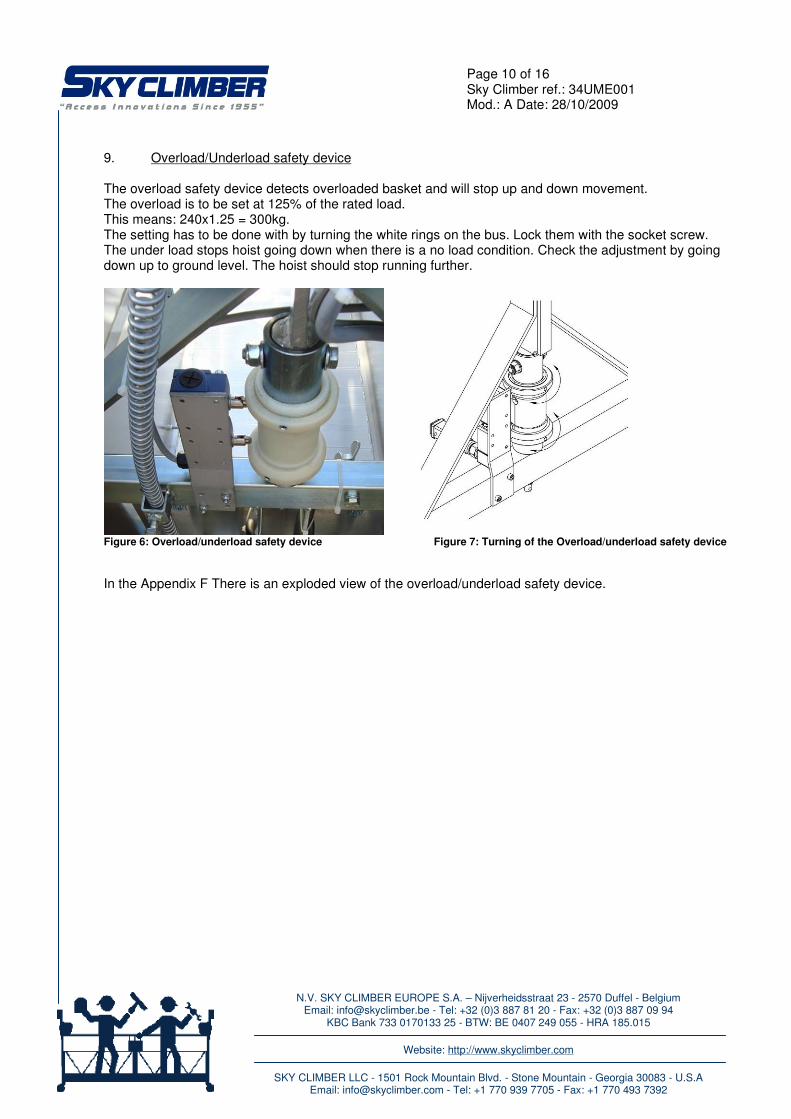
9. Overload/Underload safety device The overload safety device detects overloaded basket and will stop up and down movement. The overload is to be set at 125% of the rated load. This means: 240x1.25 = 300kg. The setting has to be done with by turning the white rings on the bus. Lock them with the socket screw. The under load stops hoist going down when there is a no load condition. Check the adjustment by going down up to ground level. The hoist should stop running further.
Figure 6: Overload/underload safety device Figure 7: Turning of the Overload/underload safety device
In the Appendix F There is an exploded view of the overload/underload safety device.

N.V. SKY CLIMBER EUROPE S.A. – Nijverheidsstraat 23 - 2570 Duffel - Belgium Email: [email protected] - Tel: +32 (0)3 887 81 20 - Fax: +32 (0)3 887 09 94
KBC Bank 733 0170133 25 - BTW: BE 0407 249 055 - HRA 185.015
Website: http://www.skyclimber.com
SKY CLIMBER LLC - 1501 Rock Mountain Blvd. - Stone Mountain - Georgia 30083 - U.S.A
Email: [email protected] - Tel: +1 770 939 7705 - Fax: +1 770 493 7392
Page 11 of 16 Sky Climber ref.: 34UME001 Mod.: A Date: 28/10/2009
10. Top limit and ultimate top limit The top limit stops the up movement of the both hoists on the PI. The ultimate top limit stops all movement of the PI. To regain mobility with the PI it must be lowered with the no power control descent ( 8. ). Mount the striker plates on both safety ropes as illustrated on the next photo.
Figure 8: striker plate
There are 3 connectors with 4 pin for each hoist. The black one is for the top limit and goes to the central control box. The blue one is for the ultimate top limit and goes to the hoist itself. The grey one is for the OL/UL device and goes to the hoist.
Figure 9: picture of the electrobox with plugs Figure 10: picture TL and UTL
Ultimate Top limit
Top Limit

N.V. SKY CLIMBER EUROPE S.A. – Nijverheidsstraat 23 - 2570 Duffel - Belgium Email: [email protected] - Tel: +32 (0)3 887 81 20 - Fax: +32 (0)3 887 09 94
KBC Bank 733 0170133 25 - BTW: BE 0407 249 055 - HRA 185.015
Website: http://www.skyclimber.com
SKY CLIMBER LLC - 1501 Rock Mountain Blvd. - Stone Mountain - Georgia 30083 - U.S.A
Email: [email protected] - Tel: +1 770 939 7705 - Fax: +1 770 493 7392
Page 12 of 16 Sky Climber ref.: 34UME001 Mod.: A Date: 28/10/2009
11. Bottom limit The PI is provided with a bottom limit that stops the downward movement when bottom trip bar hits the ground or any object.
Figure 11: bottom limit trip bar and wall rollers
To manually override the bottom limit push the bottom limit override button on the central control box together with the push button down.

N.V. SKY CLIMBER EUROPE S.A. – Nijverheidsstraat 23 - 2570 Duffel - Belgium Email: [email protected] - Tel: +32 (0)3 887 81 20 - Fax: +32 (0)3 887 09 94
KBC Bank 733 0170133 25 - BTW: BE 0407 249 055 - HRA 185.015
Website: http://www.skyclimber.com
SKY CLIMBER LLC - 1501 Rock Mountain Blvd. - Stone Mountain - Georgia 30083 - U.S.A
Email: [email protected] - Tel: +1 770 939 7705 - Fax: +1 770 493 7392
Page 13 of 16 Sky Climber ref.: 34UME001 Mod.: A Date: 28/10/2009
12. Twin drum wire winders
Figure 12: Picture of wire winder
Twin drum wire winders are being used to spool the primary and secondary steel wire rope on a drum. The wire winder motor is only being activated when the basket is moved upwards. During the basket descent, the primary and secondary steel wire ropes are un-spooled from the drums that are restraint by a friction clutch. The Friction clutch has been pre-set at the factory. After a reasonable operation time the friction clutches may wear out. This is indicated when the wire winder drums are not coiling the steel wire rope really tight on the drums. During descent the steel wires ropes are being de-coiled too easily from their drums.
12.1. Installation of the twin drum wire winders Prior to operation, the primary and secondary steel wire ropes have to be reeved onto the wire winders. In order to do this, proceed as follows:
Figure 13: Example of wired wire winders Figure 14: Picture of empty wire winder
N.V. SKY CLIMBER EUROPE S.A. – Nijverheidsstraat 23 - 2570 Duffel - Belgium Email: [email protected] - Tel: +32 (0)3 887 81 20 - Fax: +32 (0)3 887 09 94
KBC Bank 733 0170133 25 - BTW: BE 0407 249 055 - HRA 185.015
Website: http://www.skyclimber.com
SKY CLIMBER LLC - 1501 Rock Mountain Blvd. - Stone Mountain - Georgia 30083 - U.S.A
Email: [email protected] - Tel: +1 770 939 7705 - Fax: +1 770 493 7392
Page 14 of 16 Sky Climber ref.: 34UME001 Mod.: A Date: 28/10/2009
1. Prior to inserting the steel wire ropes into the drums, verify that the rotation direction of the drums is
correct so that cable will wind up as indicated on figure 13. 2. First insert the Secondary steel wire rope. (This is the rope that goes through the Sky Grip). Insert the
Steel wire rope tip approx. 15 cm (6 inches) through the cut-out hole in the drum underneath the Sky Grip as marked in figure 14.
3. Give an "up" command and coil the secondary steel wire rope on the drum. Continue until there is no more slack in the secondary steel wire rope.
4. Repeat the above operation on the opposite basket side (given that the basket is equipped with two wire winders).
5. Insert the primary steel wire rope through the hoist while pushing the "UP" command button. The wire winders will rotate while you do this, but the friction clutch will slip and thus prevent pulling on the secondary rope that has already been inserted. As the primary steel wire rope reaches the opening in the primary wire winder drum, stop the upward movement and insert the primary steel wire rope through the cut-out hole of the primary wire winder drum over a distance of approx. 15 cm (6 inches).
6. Continue with the "up"-command until the primary steel wire rope is fully tensioned and almost lifts the basket of the ground.
7. Repeat the above operation on the opposite basket side (given that the basket is equipped with two wire winders).
12.2. Maintenance of the twin drum wire winders
Wire winders do not require any lubrication. Take care in keeping grease and oil away from the friction clutches. Clutch re-tightening procedure: 1. Move the basket to ground level. 2. Use a screwdriver to unlock the wire winder clutch adjustment nuts. This is done by pushing the metal lid
that locks these nuts backwards. With only two revolutions of steel wire rope around the drums, pull on the steel wire rope. The pulling force required is approx. 8 Kg (80 N or 16 lbs).
3. Use an open-end wrench (62mm) in order to tighten the wire winder clutch adjustment nuts. Rotating the clutch adjustment nut clockwise does this.
4. Re-check the required steel wire rope pulling force. 5. Repeat until the steel wire rope pulling force is within the above specification. 6. Once the pulling force is within the specification, use a screwdriver to lock the wire winder clutch
adjustment nuts. Pushing the metal lid that locks these nuts forward against the nut side does this. WARNING DO NOT set the wire winder clutch too tight. This will cause the wire winder motors to overheat and damage them.

N.V. SKY CLIMBER EUROPE S.A. – Nijverheidsstraat 23 - 2570 Duffel - Belgium Email: [email protected] - Tel: +32 (0)3 887 81 20 - Fax: +32 (0)3 887 09 94
KBC Bank 733 0170133 25 - BTW: BE 0407 249 055 - HRA 185.015
Website: http://www.skyclimber.com
SKY CLIMBER LLC - 1501 Rock Mountain Blvd. - Stone Mountain - Georgia 30083 - U.S.A
Email: [email protected] - Tel: +1 770 939 7705 - Fax: +1 770 493 7392
Page 15 of 16 Sky Climber ref.: 34UME001 Mod.: A Date: 28/10/2009
13. Additional Safety guidelines
� Read and fully understand the general SKY CLIMBER users manual V2.0 in appendix A. � Read and fully understand the SKY CLIMBER SKY GRIP user’s manual in appendix C. � The steel wire ropes may not be touched while the basket is moving up and down. � While moving, arms and legs should be inside the basket at all times. � While moving the protection hinges for the wire winders should be closed � Long hair should be retained with a hair band. � The striker plates should not be moved on the steel wire rope. � When the basket is unused unplug the power supply connector.
14. Hoist
In appendix A there is a full user’s manual about the use of the Sky Climber hoists. In appendix D there is a complete exploded view of the hoists.
15. Daily Check list: These test must be carried out before using the platform:
� Visually inspect platform for damaged, loose or missing parts. � Check the controls of the CCB. (see chapter ‘control functions’) � Double function check E-button. � Check tension of wire winder (see chapter ‘wire winder’) � Check Sky Grip. (see manual Sky Grip) � Visually inspect supply cable.
16. Maintenance of the BMU:
16.1. Routine maintenance: (every three months under normal working conditions)
� Carry out daily check list. � Check the CCB as described in chapter (maintenance CCB) � Record the hour meter. � Write a report and give copy to the owner.
16.2. Annual maintenance or every 50 running hours:
Annual Maintenance may only be performed by qualified persons authorised by Sky Climber. Appendix:
A. SKY CLIMBER general users manual V2.0 B. SKY CLIMBER SKY GRIP assembly manual C. SKY CLIMBER SKY GRIP users manual D. SKY CLIMBER Assembly manual compact S E. SKY CLIMBER Wiring Diagram - Central Control Unit F. SKY CLIMBER Assembly manual safety devices for Compact / CX

N.V. SKY CLIMBER EUROPE S.A. – Nijverheidsstraat 23 - 2570 Duffel - Belgium Email: [email protected] - Tel: +32 (0)3 887 81 20 - Fax: +32 (0)3 887 09 94
KBC Bank 733 0170133 25 - BTW: BE 0407 249 055 - HRA 185.015
Website: http://www.skyclimber.com
SKY CLIMBER LLC - 1501 Rock Mountain Blvd. - Stone Mountain - Georgia 30083 - U.S.A
Email: [email protected] - Tel: +1 770 939 7705 - Fax: +1 770 493 7392
Page 16 of 16 Sky Climber ref.: 34UME001 Mod.: A Date: 28/10/2009
REMARKS .............................................................................................................................................................. .............................................................................................................................................................. .............................................................................................................................................................. .............................................................................................................................................................. .............................................................................................................................................................. .............................................................................................................................................................. .............................................................................................................................................................. .............................................................................................................................................................. .............................................................................................................................................................. .............................................................................................................................................................. .............................................................................................................................................................. .............................................................................................................................................................. .............................................................................................................................................................. .............................................................................................................................................................. .............................................................................................................................................................. .............................................................................................................................................................. .............................................................................................................................................................. .............................................................................................................................................................. .............................................................................................................................................................. .............................................................................................................................................................. .............................................................................................................................................................. .............................................................................................................................................................. ..............................................................................................................................................................