skyline exhibits table top displays set-up...
TRANSCRIPT

Skyline Exhibits Table Top Displays
Set-Up Instructions
Click the link below to view instructions:
Skyline WindScape® Table Tops Displays
Skyline Mirage® Pop-Up Table Top Displays
Skyline Regatta Fabric Structure
Skyline 3000R Table Top Banner Display
Skyline Exalt® Curved Table Top Display
Please contact your local Skyline dealer office to
request Skyline WindScape® Table Top display
setup instructions. Thank you!

1
Table of Contents
Case IdentificationFrame Identification
Component IdentificationFrameChannelsHalogen LightsSkyTrak™ LightsPanelsEnd PanelsDetachable Graphics
Marquee HeaderShelvingProduct DisplayCase Table – Transporter CaseCase Table – Oval CaseBubble Panel
Transporter CasesOval Cases
Warranty
Set-Up
Accessories
Repacking
Mirage® is available in many sizes – from 32” tall tabletops to 92” tall backwalls. The following set-up andrepacking instructions depict our 10’ 92” Mirage, the most popular display in the world. All Mirage displaysset up using the same sequence, although the size and number of components vary between models.
Please read the entire section before attempting set-up.
Although Skyline products are designed to withstand the rigors of a heavy trade show schedule, with manyset-ups and take-downs, care should be taken when handling your display. Valuable graphic panels canbe damaged if not properly handled. Place graphic panels in protective plastic bags provided beforerepacking. Be careful not to drop panels into the case as this could damage their edges.
If you have any questions about setting up your display or have lost components, call your local Skyline distributor. For the number of your distributor, or the distributor in a city in which you are exhibiting, callSkyline at 1-800-328-2725.
Thank you for choosing Skyline – have a great show!
23
468
1012141516
172021222324
2731
35

Transporter Case (Tabletop displays have only 1 case.)
Oval Case (Tabletop displays have only 1 case.)
Cases connect for easy transporting.
To open case lid, flip latches upand rotate counter-clockwise toloosen.
Remove case connector bracketand put in a safe place forreconnecting your cases afteryour show.
Cases connect for easy transporting.
To disconnect, unbuckle straps. Tip cases forward to separatecases at base.
2
Case connectorbracket
Case Identification

Tabletop Displays
Full-Size Displays
The label on the protective bagshows what frame you have.
6’ 32” 6’ 63”6’ 52”8’ 63”
6’ 77”8’ 92”
8’ 77”10’ 92”
3
Frame Identification

4
Channels
Light package (optional)
Panels
End panels
CoreCore tray
Light cord
Transporter case
Protective bag
Frame
Transporter Case Components
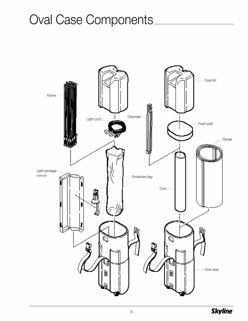
5
Channels
Foam pad
Case lid
Light package(optional)
Panels
Core
Oval case
Protective bag
Frame
Light cord
Oval Case Components
Remove frame from protectivebag in center core of case.
(Keep protective bag for repackingyour frame.)
Place frame on floor with yellowhubs facing down and towardyou.
Grasp frame rods and lift toexpand frame.
6
1
Frame
2
3
Frame
Rear
Front
Yellow hubs DOWN
Yellow hubs

Tilt frame forward to reach topconnectors.
Continue to expand frame.
When frame is fully expanded,lock one center connector tokeep the frame expanded.
Inset: Pull back on yellowsleeve, place end of connectoronto opposite hub and releaseyellow sleeve to lock.
Lock remaining connectors.
7
4
5
6
Hub
Yellowsleeve
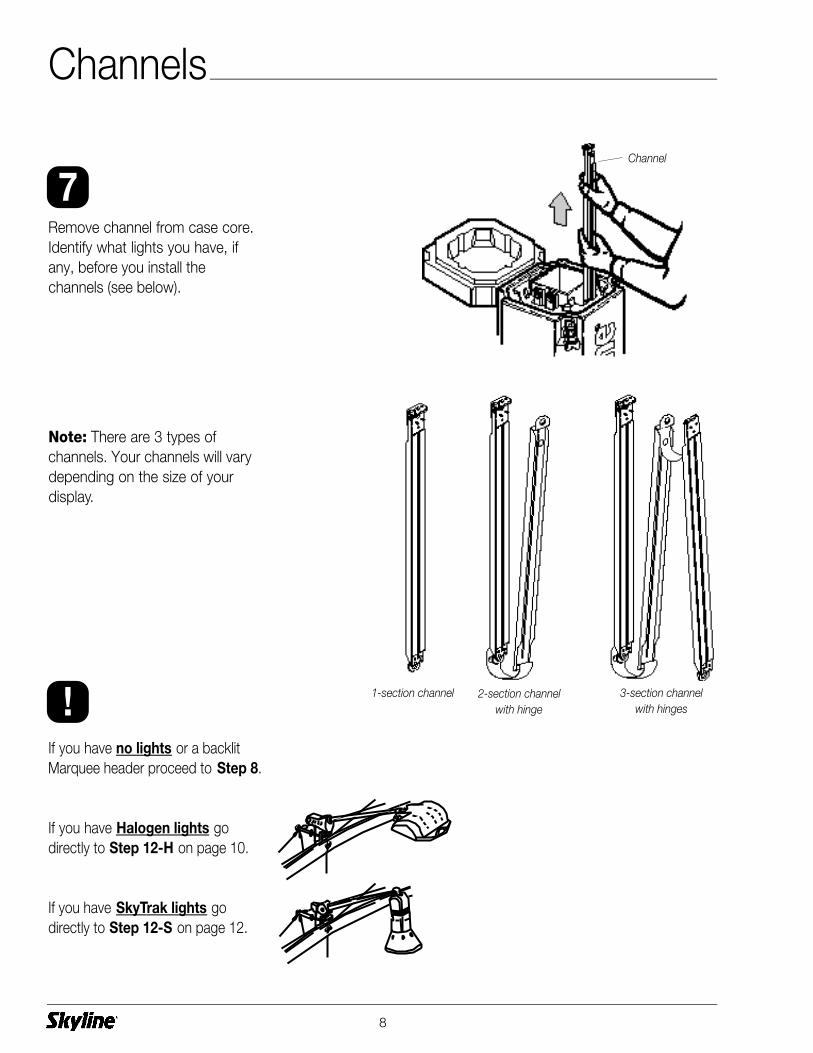
If you have no lights or a backlitMarquee header proceed to Step 8.
If you have Halogen lights godirectly to Step 12-H on page 10.
If you have SkyTrak lights godirectly to Step 12-S on page 12.
Remove channel from case core.Identify what lights you have, ifany, before you install the channels (see below).
Note: There are 3 types of channels. Your channels will varydepending on the size of yourdisplay.
1-section channel 2-section channelwith hinge
3-section channelwith hinges
8
Channel
7
!
Channels

Channels are applied to all quadrants on front side of frame.Extra channels are applied toeach end on back side of frame.
Top ConnectionConnect top channel section totop hub of display frame.
Center Connection(s)Connect bottom of top channelto hub of display frame. Slidetop of next channel up ontosame hub.
Bottom ConnectionConnect bottom of channel tohub of display frame.
9
Frame
Hub
TopChannel
TopChannel
CenterChannel
BottomChannel
Step 10
Step 11
Step 12
8
9
1 0
1 1
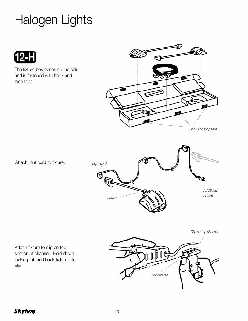
Attach light cord to fixture.
The fixture box opens on the sideand is fastened with hook andloop tabs.
Attach fixture to clip on top section of channel. Hold downlocking tab and back fixture intoclip.
10
Light cord
Hook and loop tabs
Fixture
Clip on top channel
Locking tab
12- H
AdditionalFixture
Halogen Lights

Rotate fixture 90º counter-clockwise.
Repeat for remaining fixture(s).
See Steps 8-11 for details onchannel installation.
Place channels with light fixturesin desired position on frame (seeillustration at right for typicalplacement).
Remaining channels without lightsare installed on open quadrantson front of frame and on endquadrants on back of frame.
11

Attach SkyTrak fixtures to lightcord (found in lid of Transportercase).
Attach assembled fixture to clipon top section of channel. Holddown locking tab and backfixture into clip.
The fixture box opens on the sideand is fastened with hook andloop tabs.
12
12- S
Light cord
Clip on top channel
Locking tab
SkyTrak™ Lights

Repeat for remaining fixtures.
See Steps 8-11 for details onchannel installation.
Place channels with light fixturesin desired position on frame (seeright for typical placement).
Remaining channels are installedon remaining quadrants on frontof frame (if any) and on end quad-rants on back of frame.
Rotate fixture 90º counter-clockwise.
13

Carefully remove panels from caseand unroll on flat, clean surface.
Note: Remove center core fromTransporter case to access panels.
Graphic Panel: Pull just enoughof the panel out of the bag toexpose the panel notches. Attachas desribed below(15). Oncepanel is attached, slide bag off ofpanel.
Fabric Panels: Remove panel(s)from protective bag and attach asdescribed below (15).
Save bags and protective sheets.
Grasp panels on their edges makingsure panel notches are on top.Hold the panel slightly concave togive it the rigidity needed to reachthe top of the channel.
Hook the panel notch over the pinat the top of the channel. Repeatfor other side of panel. Let panelsattach to magnetic channels.
14
Panels
Panel notch
Fabric panel
Pin
Graphic panel
Protective bag
1 3
1 4
1 5
Panels

Note: There are a variety ofend panels available for yourMirage. All styles attach in thesame manner.
Hook the panel notch over the pinat the top of the front channel. Let panel attach tomagnet on channel. Guide endpanel around to back of frameand attach in the same manner.
15
Round Marquee Flat
Front channel
Back channel
Panel notch
Pin
1 6
End Panels
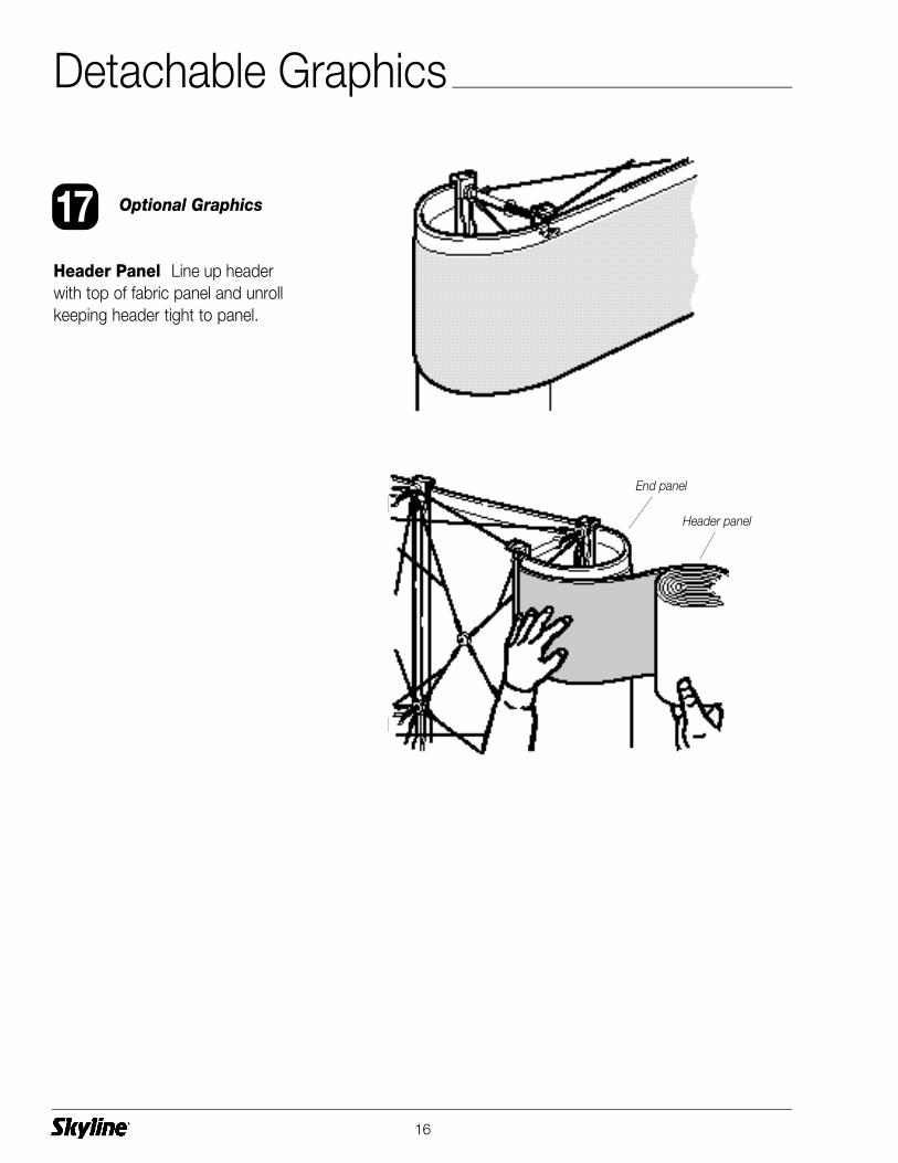
Header Panel Line up headerwith top of fabric panel and unrollkeeping header tight to panel.
Optional Graphics
16
Header panel
End panel
1 7
Detachable Graphics
17
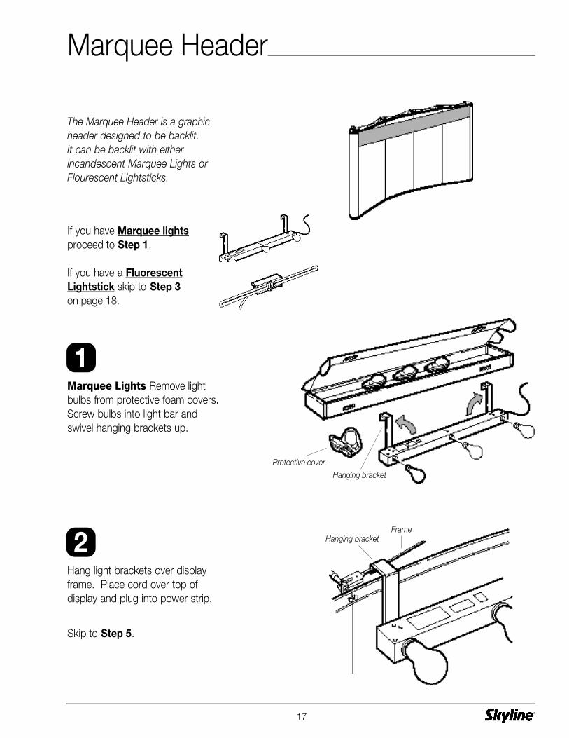
Marquee Lights Remove lightbulbs from protective foam covers.Screw bulbs into light bar andswivel hanging brackets up.
The Marquee Header is a graphicheader designed to be backlit. It can be backlit with either incandescent Marquee Lights orFlourescent Lightsticks.
Hang light brackets over displayframe. Place cord over top ofdisplay and plug into power strip.
Skip to Step 5.
If you have Marquee lightsproceed to Step 1.
If you have a FluorescentLightstick skip to Step 3on page 18.
Hanging bracket
FrameHanging bracket
Protective cover
1
2
Marquee Header

Fluorescent Lightstick Insertboth lightsticks into fixture.
Unfold hanging bracket and insertinto slots of channels in desiredposition.
Connect fixture to hanging bracket.
Place cord over top of displayand plug into power strip.
18
Fixture
(Top View)
Hanging bracket
FixtureChannel
Fluorescent lightsticks
Fixture
Single Lightstick
Double Lightstick
Hanging bracket
Fluorescent lightsticks
Channel
3
4
Fluorescent lightsticks

Assemble shock-corded headerframe.
Unroll graphic panel onto headerframe.
Hook header over frame at bothends of display.
19
Frame
Hanging bracket
Graphic panel
Shockcord
Frame
5
6
7
Hanging bracket
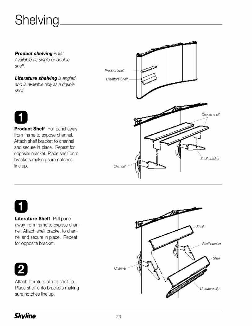
Product Shelf Pull panel awayfrom frame to expose channel.Attach shelf bracket to channeland secure in place. Repeat foropposite bracket. Place shelf ontobrackets making sure notches line up.
Product shelving is flat.Available as single or doubleshelf.
Literature shelving is angledand is available only as a doubleshelf.
Literature Shelf Pull panelaway from frame to expose chan-nel. Attach shelf bracket to chan-nel and secure in place. Repeatfor opposite bracket.
Attach literature clip to shelf lip.Place shelf onto brackets makingsure notches line up.
20
Shelf bracket
Channel
Double shelf
Shelf bracket
Shelf
Literature clip
Channel
Shelf
1
1
2
Literature Shelf
Product Shelf
Shelving

Waterfall Bracket Carefullypull panel away exposing channels.Insert bracket into channelnotches and push down to lockinto place.
Peg Bar Carefully pull panelaway exposing channels. Insertbracket into channel notches andpush down to lock into place.
Waterfall Bracket is used fordisplaying products with a hanger such as apparel.
Peg Bar is perfect for displayingpackaged items.
21
Waterfall bracket
Channel
ChannelPeg bar
Peg
1
1
Product Display

Open case lids and use caseconnector bracket to attachcases together. Replace lids andlock.
For a stationary table, positioncases with wheels facing oppositedirection.
For a moveable table, positioncases with wheels facing thesame direction.
Unfold table top and place oncases. Place cover on table top.
Attach end panels to magneticstrip on table top cover.
Attach front/back panels to mag-netic strip on table top cover andto magnetic strips on end panels.
Case table is used for productdisplay or working surface. Thecases become the structure forthe table and are covered withpanels.
Stationarytable
Moveabletable
22
Case connector bracket
Table top
Front panel
End panel
Cover panel
1
2
3
4
Case Table – Transporter Case

Place lids on oval cases at theirlow position. Rotate lid 1/2 turnfor high/low positions.
Tip cases forward and connectcases at their base. Strap casestogether.
Connect table top halves andplace on cases.
Starting at the back of the case,attach panel to manetic strip onbase of table top. Wrap aroundcases.
Case table is used for productdisplay or working surface. Thecases become the structure for thetable and is covered with a panel.
23
Panel
Table top halves
Low Position(for case table)
High Position(for shipping)
1
2
3
4
Case Table – Oval Case
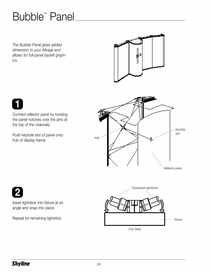
Insert lightstick into fixture at anangle and snap into place.
Repeat for remaining lightstick.
Connect reflector panel by hookingthe panel notches over the pins atthe top of the channels.
Push keyhole slot of panel ontohub of display frame.
The Bubble Panel gives addeddimension to your Mirage andallows for full-panel backlit graph-ics.
24
1
2
Fixture
(Top View)
Fluorescent lightsticks
Keyholeslot
Reflector panel
Hub
Bubble™ Panel
25
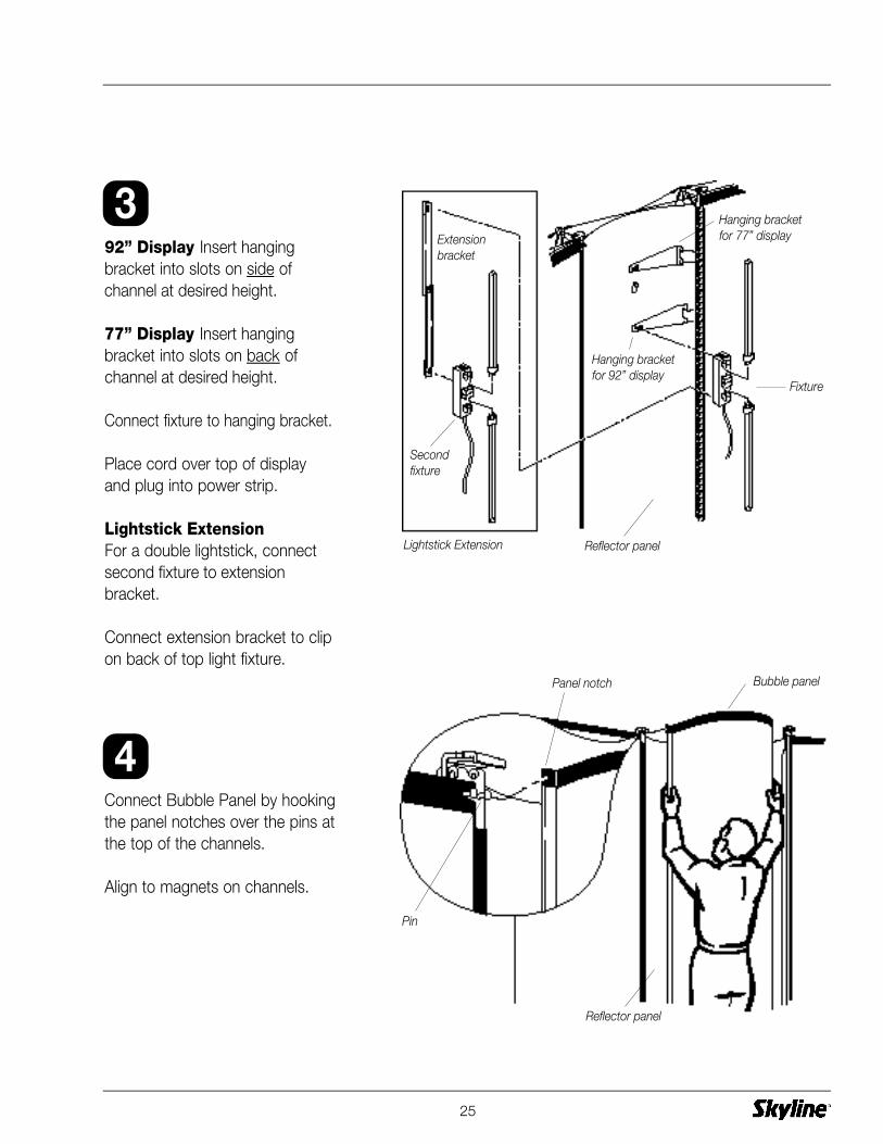
92” Display Insert hangingbracket into slots on side ofchannel at desired height.
77” Display Insert hangingbracket into slots on back ofchannel at desired height.
Connect fixture to hanging bracket.
Place cord over top of displayand plug into power strip.
Lightstick ExtensionFor a double lightstick, connectsecond fixture to extensionbracket.
Connect extension bracket to clipon back of top light fixture.
Connect Bubble Panel by hookingthe panel notches over the pins atthe top of the channels.
Align to magnets on channels.
Hanging bracketfor 77” display
Hanging bracketfor 92” display
Extensionbracket
Lightstick Extension
Fixture
Secondfixture
3
4
Bubble panelPanel notch
Pin
Reflector panel
Reflector panel

Additional Accessories
Additional accessories are availablefrom your Skyline distributor andmay be included with your display.Set-up instructions are includedwithin the accessory container oras a label on the container itself.
26

27
Channels
Light package (optional)
Panels
End panels
Core
Core tray
Light cord
Transporter case
Protective bag
Frame
Shown below is the repacking scheme for a full-size Mirage display. Your components may vary.Carefully follow the take-down steps on pages 28-30.
Repacking – Transporter Case

Remove any accesories or lightingand replace in original packing.
Graphic Panels To keep yourpanel from dirt and scratches,place protective plastic bag ontopanel while it is on the frame.Begin at bottom of panel andmove upwards. Remove panelwhen near the top.
Roll panel and place in case. Unroll panel until tight against wallof case.
Repeat with remaining front panels.
Fabric Panels Remove 2 frontpanels and lay face-to-face withprotective sheet between.
Place in protective plastic bag.
Roll panels and place in case. Unroll panels until tight againstwall of case.
Repeat with remaining front panels.
Repeat with end panels.
28
Protective bag
Panels
End panels
Graphic panel
1
2
3
!
Protective sheet
Fabric panels
Protective sheet
Repacking – Transporter Case
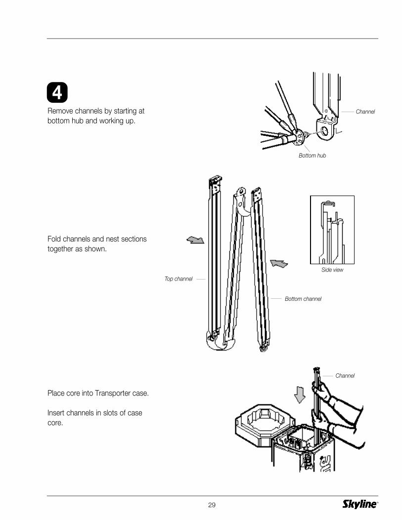
Remove channels by starting atbottom hub and working up.
Fold channels and nest sectionstogether as shown.
29
Bottom hub
Channel
Channel
Side view
4
Bottom channel
Top channel
Place core into Transporter case.
Insert channels in slots of casecore.
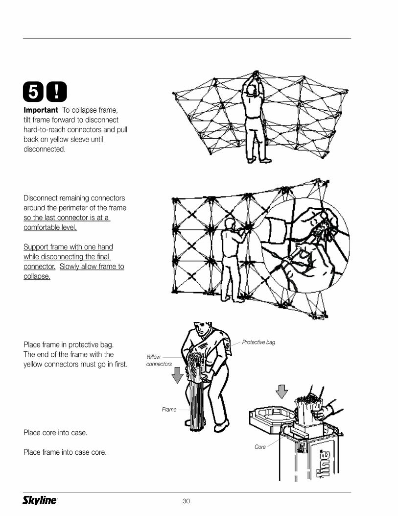
Important To collapse frame, tilt frame forward to disconnect hard-to-reach connectors and pullback on yellow sleeve until disconnected.
Disconnect remaining connectorsaround the perimeter of the frameso the last connector is at a comfortable level.
Support frame with one handwhile disconnecting the final connector. Slowly allow frame tocollapse.
Place frame in protective bag.The end of the frame with the yellow connectors must go in first.
Place core into case.
Place frame into case core.
30
Protective bag
Frame
Core
5
Yellow connectors
!
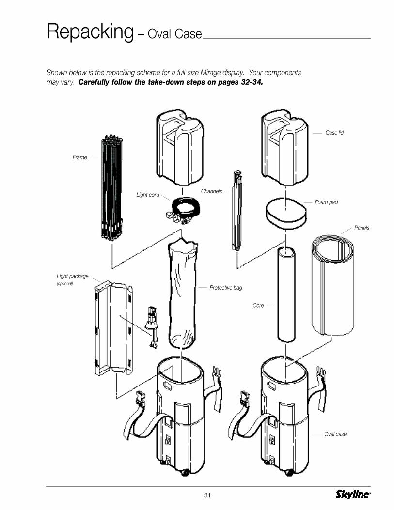
Shown below is the repacking scheme for a full-size Mirage display. Your componentsmay vary. Carefully follow the take-down steps on pages 32-34.
31
Channels
Foam pad
Case lid
Light package (optional)
Panels
Core
Oval case
Protective bag
Frame
Light cord
Repacking – Oval Case
32
Remove any accesories or lightingand replace in original packing.
Fabric Panels Remove 2 frontpanels and lay face-to-face withprotective sheet between.
Place in protective plastic bag.
Roll panels and place in case. Unroll panels until tight againstwall of case.
Repeat with remaining front panels.
Graphic Panels To keep yourpanel from dirt and scratches,place protective plastic bag ontopanel while it is on the frame.Begin at bottom of panel andmove upwards. Remove panelwhen near the top.
Roll panel and place in case. Unroll panel until tight against wallof case.
Repeat with remaining front panels.
Repeat with end panels.
Protective bag
Graphic panel
Panels
1
2
3
!
Protective sheet
Fabric panels
End panelsProtective sheet
Repacking – Oval Case

Remove channels by starting atbottom hub and working up.
Fold channels as shown.
33
Bottom hub
Channel
4
Side view
Bottom channel
Top channel
CorePlace core into oval case.
Place channels in core.
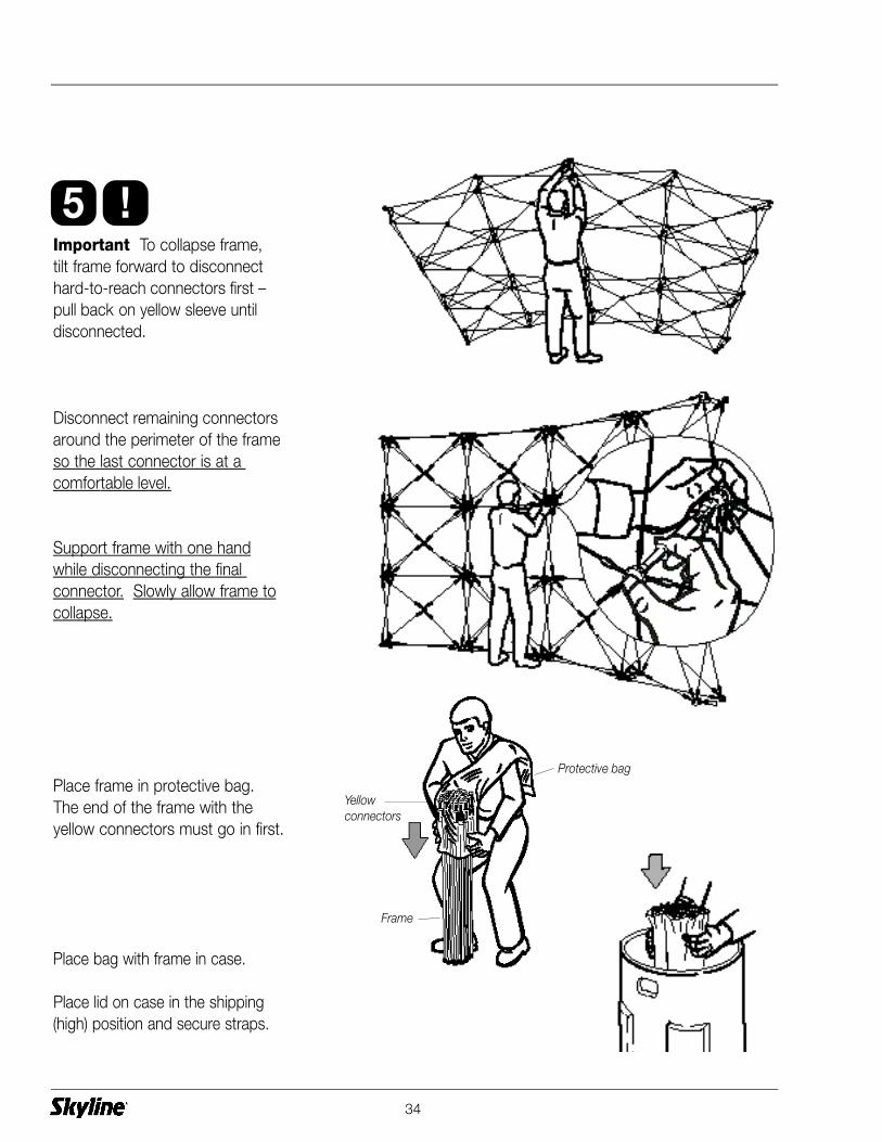
Important To collapse frame, tilt frame forward to disconnecthard-to-reach connectors first –pull back on yellow sleeve untildisconnected.
Disconnect remaining connectorsaround the perimeter of the frameso the last connector is at a comfortable level.
Support frame with one handwhile disconnecting the final connector. Slowly allow frame tocollapse.
Place frame in protective bag.The end of the frame with the yellow connectors must go in first.
Place bag with frame in case.
Place lid on case in the shipping(high) position and secure straps.
34
5
Protective bag
Frame
Yellow connectors
!

Skyline Displays, Inc.3355 Discovery Road, Eagan, Minnesota 55121 U.S.A.
SKYLINE DISPLAYS, INC., a Minnesota corporation (SKYLINE), hereby warrants to the originalbuyer, as set forth below its MIRAGE® portable display, in three parts: frame and channels(Frame and Channels), hardware (Hardware) and panels (Panels). Frame and Channels represent the collapsible frame and metal channels including attached magnets. Hardwarerepresents the shelves, brackets, case and light fixtures (not bulbs). Panels represent the flexible surface area covering the Frame and Channels. This Limited Warranty set forth belowdoes not apply to any photomural panels or graphic materials supplied by SKYLINE.
MIRAGE HARDWARE WARRANTY
SKYLINE warrants the MIRAGE Frame and Channels substantially for LIFETIME, the MIRAGEHardware for a period of one (1) year from the date of purchase, and the MIRAGE Panels fora period of ninety (90) days from the date of shipment, will be free from defects in material orworkmanship. Defects will be determined solely by SKYLINE and not by any representative,distributor, or dealer of or for SKYLINE. Upon determination of defect, the sole obligation ofSKYLINE will be to repair or replace defective part. Replacement of a defective part shall bemade by the issuance of a credit to the Buyer which may be used by the Buyer to purchase areplacement part.
The conditions of the Limited Warranty (1) the MIRAGE Frame and Channels, Hardware or Panels shall have been subject to only normal use and service and shall not have been misused, neglected, altered or otherwise damaged and (2) there shall be no evidence or tampering or deliberate destruction.
No representative, distributor, or dealer of or for SKYLINE is authorized to assume for SKYLINEany other obligations or liabilities in connection with the MIRAGE Frame and Channels, Hardware or Panels, or alter the terms of this Limited Warranty in any way. This LimitedWarranty is limited to the express provisions contained herein and does not extend to the liability for labor cost incurred in replacing defective parts.
Authorization to return any alleged defective part must be obtained from SKYLINE before thealleged defective part is returned. All shipping and transportation charges must be prepaid bythe buyer. SKYLINE will not accept charges for parts purchased unless the conditions of theLimited Warranty have been satisfied.
THIS WARRANTY IS IN LIEU OF ALL OTHER WARRANTIES, EXPRESS OR IMPLIED, ANDTHE WARRANTIES OF MERCHANTABILITY AND FITNESS FOR A PARTICULAR PURPOSEARE HEREBY DISCLAIMED. Some states do not allow limitations on how long an impliedwarranty lasts, so the above limitations may not apply to you. SKYLINE DISPLAYS, INC.SHALL NOT BE LIABLE FOR DAMAGES, INCLUDING SPECIAL, INCIDENTAL, OR CONSE-QUENTIAL DAMAGES ARISING OUT OF OR IN CONNECTION WITH THE PERFORMANCEOF THIS MIRAGE PRODUCT OR ITS USE BY THE BUYER.
35
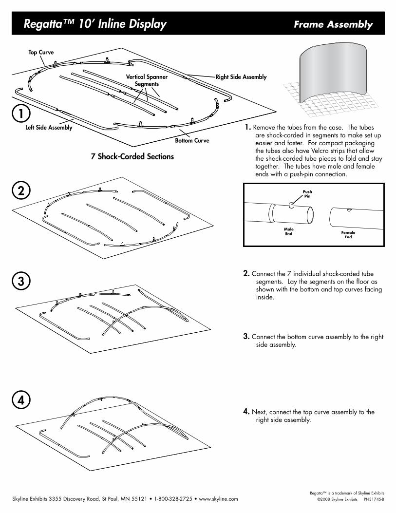
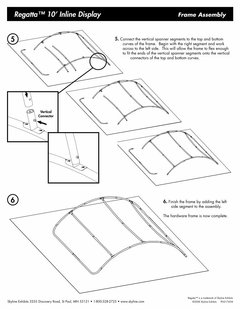
Regatta™ 10’ Inline Display Frame Assembly
Regatta™ is a trademark of Skyline Exhibits Skyline Exhibits 3355 Discovery Road, St Paul, MN 55121 • 1-800-328-2725 • www.skyline.com ©2008 Skyline Exhibits PN31745-B
1. Remove the tubes from the case. The tubes are shock-corded in segments to make set up easier and faster. For compact packaging the tubes also have Velcro strips that allow the shock-corded tube pieces to fold and stay together. The tubes have male and female ends with a push-pin connection.
2. Connect the 7 individual shock-corded tube segments. Lay the segments on the floor as shown with the bottom and top curves facing inside.
3. Connect the bottom curve assembly to the right side assembly.
4. Next, connect the top curve assembly to the right side assembly.
2
1
3
4
Top Curve
Right Side Assembly
Left Side Assembly
Bottom Curve
Vertical Spanner Segments
7 Shock-Corded Sections
Regatta™ is a trademark of Skyline Exhibits Skyline Exhibits 3355 Discovery Road, St Paul, MN 55121 • 1-800-328-2725 • www.skyline.com ©2008 Skyline Exhibits PN31745-B
Regatta™ 10’ Inline Display Frame Assembly
5
6 6. Finish the frame by adding the left side segment to the assembly.
The hardware frame is now complete.
5. Connect the vertical spanner segments to the top and bottom curves of the frame. Begin with the right segment and work across to the left side. This will allow the frame to flex enough to fit the ends of the vertical spanner segments onto the vertical
connectors of the top and bottom curves.
Vertical Connector

Regatta™ 10’ Inline Display
Regatta™ is a trademark of Skyline Exhibits Skyline Exhibits 3355 Discovery Road, St Paul, MN 55121 • 1-800-328-2725 • www.skyline.com ©2008 Skyline Exhibits PN31745-B
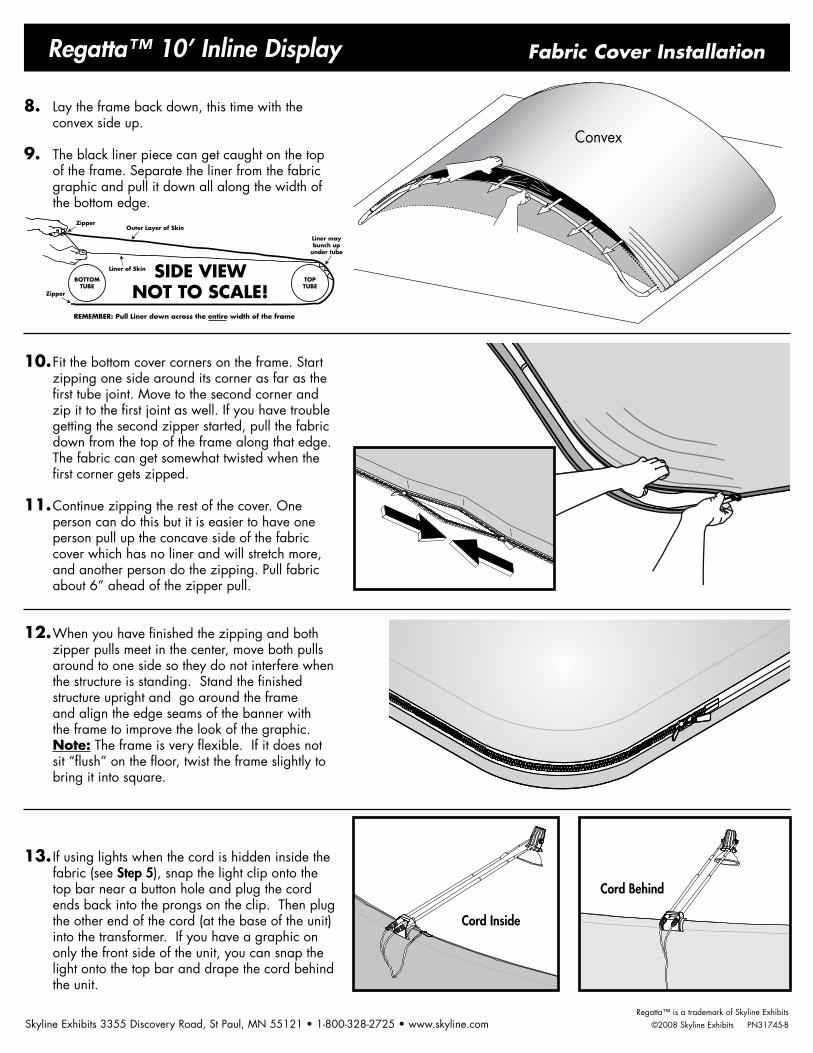
Fabric Cover Installation
Concave
Transformer
Cord
Prongs
Light clip
It is recommended that you use the white cot-ton gloves that are included to help keep the fabric clean during handling.
1. Set the frame upright so you can lay the provided plastic sheeting - found in the blue nylon envelope - on the floor to keep the fabric clean while installing.
2. Lay the frame back down on top of the plastic with concave side up.
3. Remove the fabric cover from the nylon storage bag, unzip the cover and spread it out on the floor. The liner side of the cover goes on the convex side of the frame.
4. Slide pillowcase-like cover over the frame about half way.
5. If installing lights where the cord will be hidden inside the fabric, unplug the cord from the prongs of the light clip and from the transformer. Thread the cord through one of the 3 button holes in the top and the single button hole in the bottom. Leave about 12” of cord protruding from the top. See Step 13 to finish light installation.
6. Stand the frame up and the cover will easily slide down over the frame.
7. Fit the top corners tightly on the frame
Regatta™ is a trademark of Skyline Exhibits Skyline Exhibits 3355 Discovery Road, St Paul, MN 55121 • 1-800-328-2725 • www.skyline.com ©2008 Skyline Exhibits PN31745-B
Regatta™ 10’ Inline Display Fabric Cover Installation
SIDE VIEWNOT TO SCALE!
TOPTUBE
BOTTOMTUBE
Outer Layer of Skin
REMEMBER: Pull Liner down across the entire width of the frame
Liner of Skin
Liner maybunch up
under tube
Zipper
Zipper
Convex
8. Lay the frame back down, this time with the convex side up.
9. The black liner piece can get caught on the top of the frame. Separate the liner from the fabric graphic and pull it down all along the width of the bottom edge.
10. Fit the bottom cover corners on the frame. Start zipping one side around its corner as far as the first tube joint. Move to the second corner and zip it to the first joint as well. If you have trouble getting the second zipper started, pull the fabric down from the top of the frame along that edge. The fabric can get somewhat twisted when the first corner gets zipped.
11. Continue zipping the rest of the cover. One person can do this but it is easier to have one person pull up the concave side of the fabric cover which has no liner and will stretch more, and another person do the zipping. Pull fabric about 6” ahead of the zipper pull.
12. When you have finished the zipping and both zipper pulls meet in the center, move both pulls around to one side so they do not interfere when the structure is standing. Stand the finished structure upright and go around the frame and align the edge seams of the banner with the frame to improve the look of the graphic. Note: The frame is very flexible. If it does not sit “flush” on the floor, twist the frame slightly to bring it into square.
13. If using lights when the cord is hidden inside the fabric (see Step 5), snap the light clip onto the top bar near a button hole and plug the cord ends back into the prongs on the clip. Then plug the other end of the cord (at the base of the unit) into the transformer. If you have a graphic on only the front side of the unit, you can snap the light onto the top bar and drape the cord behind the unit.
Cord Inside
Cord Behind
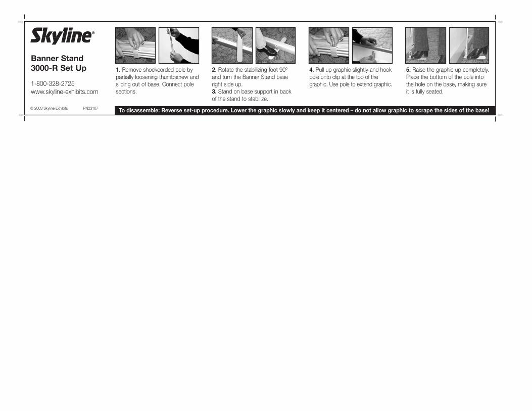
Banner Stand 3000-R Set Up 1. Remove shockcorded pole by
partially loosening thumbscrew andsliding out of base. Connect polesections.
2. Rotate the stabilizing foot 90ºand turn the Banner Stand baseright side up.3. Stand on base support in backof the stand to stabilize.
4. Pull up graphic slightly and hookpole onto clip at the top of thegraphic. Use pole to extend graphic.
5. Raise the graphic up completely.Place the bottom of the pole intothe hole on the base, making sureit is fully seated.
© 2003 Skyline Exhibits PN23107
1-800-328-2725www.skyline-exhibits.com
To disassemble: Reverse set-up procedure. Lower the graphic slowly and keep it centered – do not allow graphic to scrape the sides of the base!
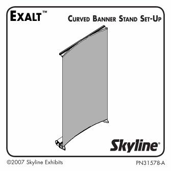
©2007 Skyline Exhibits PN31578-A
Curved Banner Stand Set-up

©2007 Skyline ExhibitsPN31578-A 2
Prepare banner stand base:1. Rotate end feet out towards the front of the unit until they stop.
2. Connect pole sections and insert pole into hole in base.

©2007 Skyline Exhibits PN31578-A3
Extend graphic:3. Tilting unit back, pull top trim up pole, keeping graphic centered.
4. Pull graphic slightly past top of pole and insert hook on top trim into pole. Make sure hook is completely inserted!

©2007 Skyline ExhibitsPN31578-A �
5. Tilt unit forward and rotate center foot to back of unit. Stand unit upright.

©2007 Skyline Exhibits PN31578-A5
Create curved graphic:6. Push forward where orange dots are located on top and bottom flexible trim strips. Swing metal braces on trim strips out on each side, top and bottom, to “set” the curve.
TOP
BOTTOM

©2007 Skyline ExhibitsPN31578-A �
Remove fabric ripples at bottom:7. From the back, near the curved trim, pull lightly on both sides of the banner at the same time.
©2007 Skyline Exhibits PN31578-A7
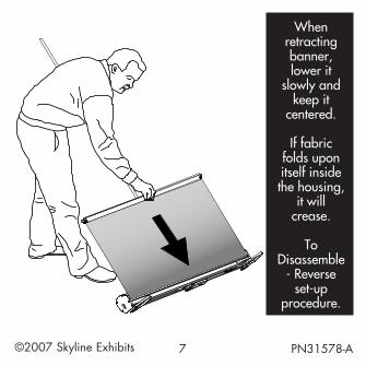
When retracting banner, lower it
slowly and keep it
centered.
If fabric folds upon itself inside the housing,
it will crease.
To Disassemble
- Reverse set-up
procedure.

PN31578-A
Patent Pending1-800-328-2725www.skyline.com
©2007 Skyline Exhibits