skypilot network administration - trillant network administration | iii about this guide this...
TRANSCRIPT

SkyPilot Network Administration
671-00009-01 Rev B

© 2006 SkyPilot Networks, Inc. All rights reservedThis publication, or parts thereof, may not be reproduced in any form, by any method, for any purpose.
Product specifications are subject to change without notice. This material is provided for informational purposes only; SkyPilot assumes no liability related to its use and expressly disclaims any implied warranties of merchantability or fitness for any particular purpose.
SkyPilot TrademarksSkyConnector, SkyControl, SkyExtender, SkyGateway, SkyPilot, SkyPilot Networks, SkyProvision, and the SkyPilot logo are the trademarks and registered trademarks of SkyPilot Networks, Inc.
Third-Party TrademarksJava and all Java-based trademarks and logos are trademarks or registered trademarks of Sun Microsystems, Inc. in the United States and other countries.
MySQL is a registered trademark of MySQL AB in the United States, the European Union, and other countries.
All other designated trademarks, trade names, logos, and brands are the property of their respective owners.
Third-Party Software Program CreditsThis product includes software developed by the Apache Software Foundation (http://www.apache.org/), licensed under the Apache License.
This product includes the DHCP Server software from Internet Systems Consortium, licensed under the DHCP License. The DHCP Server software is copyright © 2004 Internet Systems Consortium, Inc. (“ISC”). Copyright © 1995–2003 Internet Software Consortium. All rights reserved. Redistribution and use in source and binary forms, with or without modification, are permitted provided that the following conditions are met: 1. Redistributions of source code must retain the above copyright notice, this list of conditions and the following disclaimer. 2. Redistributions in binary form must reproduce the above copyright notice, this list of conditions and the following disclaimer in the documentation and/or other materials provided with the distribution. 3. Neither the name of ISC, ISC DHCP, nor the names of its contributors may be used to endorse or promote products derived from this software without specific prior written permission. THIS SOFTWARE IS PROVIDED BY INTERNET SYSTEMS CONSORTIUM AND CONTRIBUTORS “AS IS” AND ANY EXPRESS OR IMPLIED WARRANTIES, INCLUDING, BUT NOT LIMITED TO, THE IMPLIED WARRANTIES OF MERCHANTABILITY AND FITNESS FOR A PARTICULAR PURPOSE ARE DISCLAIMED. IN NO EVENT SHALL ISC OR CONTRIBUTORS BE LIABLE FOR ANY DIRECT, INDIRECT, INCIDENTAL, SPECIAL, EXEMPLARY, OR CONSEQUENTIAL DAMAGES (INCLUDING, BUT NOT LIMITED TO, PROCUREMENT OF SUBSTITUTE GOODS OR SERVICES; LOSS OF USE, DATA, OR PROFITS; OR BUSINESS INTERRUPTION) HOWEVER CAUSED AND ON ANY THEORY OF LIABILITY, WHETHER IN CONTRACT, STRICT LIABILITY, OR TORT (INCLUDING NEGLIGENCE OR OTHERWISE) ARISING IN ANY WAY OUT OF THE USE OF THIS SOFTWARE, EVEN IF ADVISED OF THE POSSIBILITY OF SUCH DAMAGE.
This product includes the FTP Server software from vsftpd (http://vsftpd.beasts.org/), licensed under the GNU General Public License.
This product includes Java software from Sun Microsystems, licensed under Sun Microsystems' Binary Code License Agreement. Copyright 2003, Sun Microsystems, Inc. All rights reserved. Use is subject to license terms. Sun, Sun Microsystems, the Sun logo, Solaris, Java, the Java Coffee Cup logo, J2SE, and all trademarks and logos based on Java are trademarks or registered trademarks of Sun Microsystems, Inc. in the U.S. and other countries.
This product includes JBOSS Version 3.2.3 software from JBoss, licensed under the GNU Lesser General Public License. Some bundled products in JBOSS are licensed under the Apache License.
This product contains Java Telnet Application (JTA 2.0).
This product contains the MibBrowser software from Mibble.
This product includes software the copyright of which is owned by and licensed from MySQLAB.
This product includes software developed by the OpenSSL Project for use in the OpenSSL Toolkit. (http://www.openssl.org/). Copyright (c) 1998–2005 The OpenSSL Project. All rights reserved. Redistribution and use in source and binary forms, with or without modification, are permitted provided that the following conditions are met: 1. Redistributions of source code must retain the above copyright notice, this list of conditions and the following disclaimer. 2. Redistributions in binary form must reproduce the above copyright notice, this list of conditions and the following disclaimer in the documentation and/or other materials provided with the distribution. 3. All advertising materials mentioning features or use of this software must display the following acknowledgment: “This product includes software developed by the OpenSSL Project for use in the OpenSSL Toolkit. (http://www.openssl.org/)” 4. The names “OpenSSL Toolkit” and “OpenSSL Project” must not be used to endorse or promote products derived from this software without prior written permission. For written permission, please contact [email protected]. 5. Products derived from this software may not be called “OpenSSL” nor may “OpenSSL” appear in their names without prior written permission of the OpenSSL Project. 6. Redistributions of any form whatsoever must retain the following acknowledgment: “This product includes software developed by the OpenSSL Project for use in the OpenSSL Toolkit (http://www.openssl.org/)”. THIS SOFTWARE IS PROVIDED BY THE OpenSSL PROJECT ``AS IS'' AND ANY EXPRESSED OR IMPLIED WARRANTIES, INCLUDING, BUT NOT LIMITED TO, THE IMPLIED WARRANTIES OF MERCHANTABILITY AND FITNESS FOR A PARTICULAR PURPOSE ARE DISCLAIMED. IN NO EVENT SHALL THE OpenSSL PROJECT OR ITS CONTRIBUTORS BE LIABLE FOR ANY DIRECT, INDIRECT, INCIDENTAL, SPECIAL, EXEMPLARY, OR CONSEQUENTIAL DAMAGES (INCLUDING, BUT NOT LIMITED TO, PROCUREMENT OF SUBSTITUTE GOODS OR SERVICES; LOSS OF USE, DATA, OR PROFITS; OR BUSINESS INTERRUPTION) HOWEVER CAUSED AND ON ANY THEORY OF LIABILITY, WHETHER IN CONTRACT, STRICT LIABILITY, OR TORT (INCLUDING NEGLIGENCE OR OTHERWISE) ARISING IN ANY WAY OUT OF THE USE OF THIS SOFTWARE, EVEN IF ADVISED OF THE POSSIBILITY OF SUCH DAMAGE.
This product includes libraries developed by Eric Young and is licensed under the Original SSLeay License. This product includes cryptographic software written by Eric Young ([email protected]). This product includes software written by Tim Hudson ([email protected]). Copyright (C) 1995–1998 Eric Young ([email protected]). All rights reserved. Redistribution and use in source and binary forms, with or without modification, are permitted provided that the following conditions are met: 1. Redistributions of source code must retain the copyright notice, this list of conditions and the following disclaimer. 2. Redistributions in binary form must reproduce the above copyright notice, this list of conditions and the following disclaimer in the documentation and/or other materials provided with the distribution. 3. All advertising materials mentioning features or use of this software must display the following acknowledgement: “This product includes cryptographic software written by Eric Young ([email protected])” The word 'cryptographic' can be left out if the routines from the library being used are not cryptographic related :-). 4. If you include any Windows specific code (or a derivative thereof ) from the apps directory (application code) you must include an acknowledgement: “This product includes software written by Tim Hudson ([email protected])”. THIS SOFTWARE IS PROVIDED BY ERIC YOUNG ``AS IS'' AND ANY EXPRESS OR IMPLIED WARRANTIES, INCLUDING, BUT NOT LIMITED TO, THE IMPLIED WARRANTIES OF MERCHANTABILITY AND FITNESS FOR A PARTICULAR PURPOSE ARE DISCLAIMED. IN NO EVENT SHALL THE AUTHOR OR CONTRIBUTORS BE LIABLE FOR ANY DIRECT, INDIRECT, INCIDENTAL, SPECIAL, EXEMPLARY, OR CONSEQUENTIAL DAMAGES (INCLUDING, BUT NOT LIMITED TO, PROCUREMENT OF SUBSTITUTE GOODS OR SERVICES; LOSS OF USE, DATA, OR PROFITS; OR BUSINESS INTERRUPTION) HOWEVER CAUSED AND ON ANY THEORY OF LIABILITY, WHETHER IN CONTRACT, STRICT LIABILITY, OR TORT (INCLUDING NEGLIGENCE OR OTHERWISE) ARISING IN ANY WAY OUT OF THE USE OF THIS SOFTWARE, EVEN IF ADVISED OF THE POSSIBILITY OF SUCH DAMAGE.
This product includes SNMP software from WestHawk, licensed under the WestHawk License.
This product includes JFreeCharts from http://www.jfree.org/, licensed under GNU Lesser General Public License.
This product includes JasperReports from http://jasperreports.sourceforge.net/index.html, licensed under GNU Lesser Public License.
GOVERNMENT USEThe following provision applies to United States Government end users. This product is comprised of “commercial computer software” and “commercial computer software documentation” as such terms are used in 48 C.F.R. 12.212 and are provided to the Government (i) for acquisition by or on behalf of civilian agencies, consistent with the policy set forth in 48 C.F.R. 12.212; or (ii) for acquisition by or on behalf of units of the Department of Defense, consistent with the policies set forth in 48 C.F.R. 227.7202-1 and 227.7202-3.
SkyPilot EMS 1.5Document Last Revised: April 10, 2007

SkyPilot Network Administration | iii
About This Guide
This document contains guidelines for performing operations, administration, and
maintenance tasks for SkyPilot™ network deployments. Topics discussed include
using SkyProvision™ to provision SkyPilot devices, using SkyControl™ to monitor a
SkyPilot network, and troubleshooting.
This chapter explains what’s in this guide and how it’s organized.
Chapter HighlightsAudience and purpose
How this guide is organized
Conventions used in this guide
iv | About This Guide
Audience and PurposeThis guide is intended for administrators who are responsible for managing a
SkyPilot network. It explains ongoing operations, administration, and
maintenance tasks, such as provisioning SkyPilot devices, customizing a SkyPilot
network, and monitoring SkyPilot network status.
This guide assumes administrator-level knowledge of IP networks, basic
knowledge of wireless networking, and a familiarity with the information in
Getting Started with the SkyPilot Network. Additionally, the procedures assume that
SkyPilot devices have already been successfully installed according to the
procedures in their installation guides. (Complete SkyPilot documentation is
available on the SkyPilot website at www.skypilot.com/support/.)
How This Guide Is OrganizedThis guide is organized as follows:
Chapter 1, “Introduction,” describes the SkyPilot Networks hardware and
software components, as well as the operations, administration, and
maintenance tasks that you can perform.
Chapter 2, “Operations,” describes how to provision SkyPilot devices (either
manually or automatically) and provides guidelines for configuring SkyPilot
devices.
Chapter 3, “Administration,” describes routine management tasks, such as
managing software and customers, configuring security, and creating reports,
and directs you to the corresponding detailed procedures.
Chapter 4, “Maintenance,” describes techniques for maintaining your SkyPilot
network, as well as solutions to common troubleshooting issues.

Conventions Used in This Guide | v
Appendix A, “General SkyPilot EMS Reference,” provides detailed instructions
for SkyPilot network management and monitoring functions that aren’t
specific to SkyProvision or SkyControl, such as security configuration and alarm
monitoring.
Appendix B, “SkyProvision Reference,” provides detailed instructions for
configuring provisioning parameters for automatically provisioned devices,
and for performing administrative functions for your SkyPilot network.
Appendix C, “Google Earth EMS Reference,” provides instructions for preparing
network profiles for viewing in Google Earth.
Appendix D, “SkyControl Reference,” provides detailed instructions for SkyPilot
network administrative and maintenance functions.
Appendix E, “Configuring a Firewall for SkyPilot Operations,” tells you which
ports to open for data traffic from SkyPilot devices if your server is behind a
firewall.
Appendix F, “Access Point Command-Line Interface,” provides instructions for
accessing an access point’s Linux command shell.
Conventions Used in This GuideThis section describes the text and syntax conventions used in this guide.
Text Conventions
This guide uses the following text conventions:
Italic is used to introduce new terms.
Bold is used to indicate what you click in a graphical user interface (for
example, commands names). In examples showing user interaction with the
command-line interface, bold is used to indicate user input as opposed to
command output.
A monospace font is used for code elements (variable names, data values,
function names, and so forth), command lines, scripts, and source code
listings. It is also used to indicate text to enter in a graphical user interface.
Italic-monospace is used for replaceable elements and placeholders
within code listings.

vi | About This Guide
Syntax Conventions
This guide uses the following conventions when showing syntax:
Angle brackets, “<“ and “>”, enclose mandatory elements. You must enter
these elements. For example:ping <IP-address>
Square brackets, “[“ and “]”, enclose optional elements. You can omit these
elements. For example:show filter [filter-table-number]
Square brackets are also used to show the current value of parameters in the
output of some commands.
A vertical bar, “|”, separates choices. For example:show bridge [cache | port]

SkyPilot Network Administration | vii
Contents
About This Guide . . . . . . . . . . . . . . . . . . . . . . . . . . . . . . . . . . . . vAudience and Purpose . . . . . . . . . . . . . . . . . . . . . . . . . . . . . viHow This Guide Is Organized . . . . . . . . . . . . . . . . . . . . . . . . . viConventions Used in This Guide . . . . . . . . . . . . . . . . . . . . . . .vii
Chapter 1 Introduction . . . . . . . . . . . . . . . . . . . . . . . . . . . . . 1System Overview . . . . . . . . . . . . . . . . . . . . . . . . . . . . . . . . . 2About Operations, Administration, and Maintenance . . . . . . . . . . 5
Chapter 2 Operations . . . . . . . . . . . . . . . . . . . . . . . . . . . . . . 9Provisioning Overview . . . . . . . . . . . . . . . . . . . . . . . . . . . . 10Provisioning Parameters Overview. . . . . . . . . . . . . . . . . . . . . 15Required Provisioning Parameters . . . . . . . . . . . . . . . . . . . . . 17Optional Provisioning Parameters . . . . . . . . . . . . . . . . . . . . . 23General Provisioning Guidelines . . . . . . . . . . . . . . . . . . . . . . 53Automatic Provisioning . . . . . . . . . . . . . . . . . . . . . . . . . . . . 53Manual Provisioning . . . . . . . . . . . . . . . . . . . . . . . . . . . . . . 58
Chapter 3 Administration . . . . . . . . . . . . . . . . . . . . . . . . . . . .63Managing Software Images . . . . . . . . . . . . . . . . . . . . . . . . . 64Managing Customers . . . . . . . . . . . . . . . . . . . . . . . . . . . . . 67Managing Access Control Lists . . . . . . . . . . . . . . . . . . . . . . . 68About Network Security . . . . . . . . . . . . . . . . . . . . . . . . . . . 69About Reports and Statistics . . . . . . . . . . . . . . . . . . . . . . . . . 70
Chapter 4 Maintenance . . . . . . . . . . . . . . . . . . . . . . . . . . . . .73Monitoring a Network’s Topology with SkyControl . . . . . . . . . . 74Monitoring Events and Alarms . . . . . . . . . . . . . . . . . . . . . . . 75Monitoring Link States . . . . . . . . . . . . . . . . . . . . . . . . . . . . 76Managing IP Addresses . . . . . . . . . . . . . . . . . . . . . . . . . . . . 77Using Utilities . . . . . . . . . . . . . . . . . . . . . . . . . . . . . . . . . . 79Troubleshooting . . . . . . . . . . . . . . . . . . . . . . . . . . . . . . . . 79
Appendix A General SkyPilot EMS Reference. . . . . . . . . . . . . . . . 101Using SkyPilot EMS (Java Client) . . . . . . . . . . . . . . . . . . . . . .102Managing Network Security . . . . . . . . . . . . . . . . . . . . . . . . .108Configuring Traps . . . . . . . . . . . . . . . . . . . . . . . . . . . . . . .109Configuring Performance Thresholds . . . . . . . . . . . . . . . . . . .110Configuring Events. . . . . . . . . . . . . . . . . . . . . . . . . . . . . . .112

viii | Contents
Configuring Alarms . . . . . . . . . . . . . . . . . . . . . . . . . . . . . . 113
Appendix B SkyProvision Reference . . . . . . . . . . . . . . . . . . . . . 115Using SkyProvision . . . . . . . . . . . . . . . . . . . . . . . . . . . . . . 116SkyPilot EMS Web Client . . . . . . . . . . . . . . . . . . . . . . . . . . . 116Searching for Provisioning Objects . . . . . . . . . . . . . . . . . . . . 124Configuring Domains . . . . . . . . . . . . . . . . . . . . . . . . . . . . . 124Configuring Software Images . . . . . . . . . . . . . . . . . . . . . . . . 125Configuring Access Point Profiles . . . . . . . . . . . . . . . . . . . . . 126Configuring Node Profiles . . . . . . . . . . . . . . . . . . . . . . . . . . 133Configuring Nodes . . . . . . . . . . . . . . . . . . . . . . . . . . . . . . 138Configuring VLANs . . . . . . . . . . . . . . . . . . . . . . . . . . . . . . 141Configuring Proxy Proxy ARP . . . . . . . . . . . . . . . . . . . . . . . . 142Configuring Customers. . . . . . . . . . . . . . . . . . . . . . . . . . . . 145Configuring SNMP Parameters . . . . . . . . . . . . . . . . . . . . . . . 146Configuring Access Control Lists . . . . . . . . . . . . . . . . . . . . . . 149Configuring QoS . . . . . . . . . . . . . . . . . . . . . . . . . . . . . . . . 150Configuring Web Servers. . . . . . . . . . . . . . . . . . . . . . . . . . . 150
Appendix C Google Earth EMS Reference . . . . . . . . . . . . . . . . . . 151Starting Google Earth EMS. . . . . . . . . . . . . . . . . . . . . . . . . . 153Downloading icons . . . . . . . . . . . . . . . . . . . . . . . . . . . . . . 155Creating and viewing network profiles . . . . . . . . . . . . . . . . . . 156
Appendix D SkyControl Reference . . . . . . . . . . . . . . . . . . . . . . 169Using SkyControl. . . . . . . . . . . . . . . . . . . . . . . . . . . . . . . . 170Viewing Your SkyPilot Network. . . . . . . . . . . . . . . . . . . . . . . 182Configuring SkyControl’s SNMP Queries . . . . . . . . . . . . . . . . . 185Configuring Data Collection Tasks . . . . . . . . . . . . . . . . . . . . . 187Configuring Threshold Alarms . . . . . . . . . . . . . . . . . . . . . . . 189Using Reports . . . . . . . . . . . . . . . . . . . . . . . . . . . . . . . . . . 190Viewing Statistics . . . . . . . . . . . . . . . . . . . . . . . . . . . . . . . 192
Appendix E Configuring a Firewall for SkyPilot Operations . . . . . . 195
Appendix F Access Point Command-Line Interface. . . . . . . . . . . . 197Checking VLAN Status . . . . . . . . . . . . . . . . . . . . . . . . . . . . 197Accessing the Interface . . . . . . . . . . . . . . . . . . . . . . . . . . . . 197

SkyPilot Network Administration | 1
Introduction
After becoming familiar with the SkyPilot Networks solution and deploying your SkyPilot network (as described in Getting Started with the SkyPilot Network), you’ll need to perform operations, administration, and maintenance (OAM) tasks to increase performance, stability, and reliability. This chapter describes these tasks and the tools you use to perform them.
Chapter HighlightsSystem overview
About operations, administration, and maintenance (OAM)
1
2 | Chapter 1 Introduction
System OverviewSkyPilot Networks delivers a wireless, end-to-end broadband solution that
seamlessly supports high-capacity, high-coverage networks. Designed for
managed-access networks and service providers, the SkyPilot network takes
broadband wireless the last mile with a cost-effective, robust infrastructure
solution.
SkyPilot gives carriers an opportunity to expand rapidly into new markets and
extend their offerings to include VoIP and high-bandwidth applications such as
video and location-based services.
The SkyPilot solution offers a “tipping point” for converting dial-up customers to
broadband and will help drive the growth of neighborhood “hotspots,“ offering
ubiquitous wireless connectivity to local communities.
The auto-discovery and rapid provisioning features of a SkyPilot wireless mesh
network can greatly reduce deployment and maintenance costs. Multiple
topology options and network scalability create intriguing options for rapidly
expanding a metro Wi-Fi customer base.
Hardware Components
A SkyPilot network includes the following physical components:
SkyGateway™—Operates as a base station for your wireless network. It
provides an interface between wired infrastructure and a wireless network of
subscribers who enjoy secure, high-speed access to the Internet or wide area
networks.
A SkyPilot wireless network requires at least one SkyGateway for operation. If
desired, you can add additional SkyGateways to increase network capacity or
provide redundancy. The SkyGateway typically resides at a location that offers
easy access to wired infrastructure—usually a POP or data center. For optimal

System Overview | 3
performance, the SkyGateway should be installed on an elevated site, such as
a cell tower or the top of a tall building.
NOTE There must be at least one functioning SkyGateway in your SkyPilot network before any other devices (SkyExtenders or SkyConnectors) can form communications links.
SkyExtender™—Functions as a repeater and extends the wireless range of a
SkyGateway. SkyExtenders are optional equipment; by adding them to your
network, you can expand your coverage area and provide redundancy
through SkyPilot’s mesh networking features. SkyExtenders offer a cost-
effective way to add capacity and balance network loads.
A SkyExtender’s Ethernet interface can supply local subscriber service
(creating a direct connection to the wireless network via the SkyExtender’s
Ethernet port) in addition to wirelessly forwarding data on behalf of other end
users.
For optimal performance, SkyExtenders should be installed on an elevated,
fixed location, such as a roof, tower, or utility pole.
SkyExtender DualBand—Combines the features of a SkyExtender with a
high-powered 802.11b/g access point that allows service providers and
municipalities to offer standard Wi-Fi services over great distances, for targeted
hot zones or dense, ubiquitous coverage patterns.
SkyExtender TriBand—Combines the features of a SkyExtender DualBand
with an additional radio, which is accessible through a second access point
operating in parallel with the 2.4 GHz access point. The second access point
leverages the 4.9 GHz Public Safety band, using 802.11a communication
protocol. Each access point uses a single antenna, and these antennas have
similar coverage patterns, providing a cost-effective solution for municipal
networks.
IMPORTANT From here on in this guide, all references to “SkyExtender” refer to the SkyExtender, the SkyExtender DualBand, and the SkyExtender TriBand, unless otherwise noted.

4 | Chapter 1 Introduction
SkyConnector™—Links your subscribers to the SkyPilot wireless network. An
Ethernet interface on the SkyConnector enables connecting to the
subscribers’ computers or a local area network (via a switch or router).
For flexibility of installation, SkyPilot offers two versions of the SkyConnector:
Outdoor—Designed for installation by the service provider, the outdoor version of the SkyConnector attaches to an external structure such as eaves, a roof, or a pole. In general, the outdoor SkyConnector provides greater range than the indoor unit.
Indoor—A plug-and-play network device that a subscriber can easily install without technical assistance. Advise subscribers to place the SkyConnector in a location with an optimal sight line to the SkyGateway or a SkyExtender—for example, on a windowsill or in a window frame.
Software Components
The software components of a SkyPilot system are:
SkyProvision™—A server-based application that automates device
provisioning by enabling devices to get their configuration information from
the SkyPilot EMS server. SkyProvision is also used for updating network node
firmware and for setting device and system configuration options.
SkyProvision functions are accessed using the EMS Java client or the EMS Web
client. For installation information, refer to SkyPilot EMS Installation.
SkyControl™—An SNMP management system for real-time SkyPilot device
monitoring and management. This software provides a graphical view of your
network topology with at-a-glance updates on topology, routing, and
performance.
SkyControl functions are accessed using the EMS Java client. For installation
information, refer to SkyPilot EMS Installation.
Third-party applications—Provided as part of the SkyPilot EMS server
installation. The server package includes open-source versions of FTP, HTTP,
and DHCP servers plus an open-source database for storing device
configuration information. For more information about these third-party
applications, refer to SkyPilot EMS Installation.

About Operations, Administration, and Maintenance | 5
SkyPilot command-line interface—A text-based interactive application built
into all SkyPilot devices. This interface enables you to manually provision a
device, retrieve information about the device’s status, and perform real-time
logging.
NOTE This interface is typically referred to as the “command-line interface” (without the preceding “SkyPilot”).
SkyPilot Web interface—A Web-based application built into all SkyPilot
devices. This tool provides much the same functionality as the SkyPilot
command-line interface in an easy to use graphical interface.
NOTE This interface is typically referred to as the “Web interface” (without the preceding “SkyPilot”).
Access point command-line interface—The Linux command shell interface
of DualBand and TriBand access points. This interface enables you to execute
standard Linux commands to configure and retrieve access point settings
directly (versus through the SkyPilot Web interface). This interface is intended
for SkyPilot use only.
For more information about how to use the software components, see “OAM Tools
and Resources” on page 7.
About Operations, Administration, and MaintenanceAfter deploying your SkyPilot network, you will need to perform operations,
administration, and maintenance (OAM) tasks to optimize performance and
uptime. Operations refer to ongoing provisioning and customizing activities.
Administration involves routine management tasks, such as managing software
and customers, configuring security, and creating reports. Maintenance
encompasses system monitoring, address management, and troubleshooting
strategies.

6 | Chapter 1 Introduction
OAM Tasks
A SkyPilot network administrator is usually responsible for the tasks described in
Table 1-1.
Table 1-1. OAM Tasks
Task Refer to
Provisioning SkyPilot devices “Provisioning Overview” on page 10
Managing devices’ firmware “Managing Software Images” on page 64
Creating reports “About Reports and Statistics” on page 70
Monitoring system status “Monitoring a Network’s Topology with SkyControl” on page 74
“Monitoring Events and Alarms” on page 75
“Monitoring Link States” on page 76
Troubleshooting “Troubleshooting” on page 79

About Operations, Administration, and Maintenance | 7
OAM Tools and Resources
Table 1-2 describes the tools and resources related to performing OAM tasks.
Table 1-2. OAM Tools and Resources
Tool or resource Description
SkyProvision SkyProvision is a component of SkyPilot EMS (Element Management System) that automates device provisioning by enabling devices to get their configuration information from the EMS server. Using SkyProvision, you create configuration profiles that are distributed to devices across the wireless mesh network.
For more information, see “Automatic Provisioning” on page 53.
SkyControl SkyControl is an SNMP management system for real-time SkyPilot device monitoring and management. This software provides a graphical view of your network topology with at-a-glance updates on topology, routing, and performance. Like SkyProvision, SkyControl is a component of SkyPilot EMS.
For more information, see “Monitoring a Network’s Topology with SkyControl” on page 74.
Command-line interface
A comprehensive command-line interface is built into all SkyPilot devices to enable you to manually provision a device, retrieve information about the device’s status, and perform real-time logging.
For more information, see “Command-Line Interface Provisioning” on page 61.
Web interface A comprehensive Web-based application is built into all SkyPilot devices to provide much the same functionality of the command-line interface in an easy to use graphical interface.
For more information, see “Web Interface Provisioning” on page 61.

8

SkyPilot Network Administration | 9
Operations
SkyPilot operations tasks include ongoing provisioning and customizing activities.
This chapter describes how to provision SkyPilot devices (either manually or
automatically) and provides guidelines for configuring SkyPilot devices.
Chapter HighlightsProvisioning overview
Provisioning parameters overview
Required provisioning parameters
Optional provisioning parameters
General provisioning guidelines
Automatic provisioning
Manual provisioning
2

10 | Chapter 2 Operations
Provisioning OverviewProvisioning is the process of customer authorization and service configuration.
When a SkyPilot device is provisioned, it authenticates itself on the network and
downloads a configuration file containing customer-specific settings, such as
firmware images and Quality of Service rate limits. This device provisioning is
independent of end-user provisioning, but it can be used to assist with end-user
provisioning by serving IP addresses via DHCP to user equipment such as personal
computers and home routers.
Table 2-1 summarizes the steps required to provision a SkyPilot device.
Choosing a Device Provisioning Mode
SkyPilot offers a choice of two device provisioning modes:
Automatic—Allows unattended configuration of SkyPilot devices from a
central SkyPilot EMS server at your network operations center (NOC).
Automatic provisioning requires more initial setup time than manual
provisioning, but it greatly simplifies network administration as your network
grows.
Manual—Allows device configuration with the minimum settings required for
a wireless link. Configuration settings are entered through the command-line
interface or Web interface and are stored in flash memory; manually
provisioned devices do not depend on a SkyPilot EMS server for configuration.
Manual provisioning is a logical choice if you’re installing a test network or
rolling out a small-scale installation that’s not expected to expand.
Table 2-1. Device Provisioning Steps
Step Refer to
1 Decide whether to configure the device for manual or automatic provisioning.
“Choosing a Device Provisioning Mode” on page 10
2 Provision the device. Either of the following:
“Manual Provisioning” on page 58
“Automatic Provisioning” on page 53

Provisioning Overview | 11
Provisioning Mode and Device Operations
The provisioning mode you choose for devices (automatic or manual) affects the
procedure that the devices use to come online.
Figures 2-1 and 2-2 illustrate the steps taken by devices—both manually and
automatically provisioned—from power-on through the formation of network
links.
Figure 2-1 shows the steps taken by a SkyGateway up to the point at which the
device begins sending hello beacons, which other SkyPilot devices can use to
form links on the wireless network.
Figure 2-2 shows the steps taken by SkyExtenders and SkyConnectors up to
the point at which the device starts forming links with other devices on the
wireless network.

12 | Chapter 2 Operations
Figure 2-1. SkyGateway power-on and link formation

Provisioning Overview | 13
Figure 2-2. SkyConnector/SkyExtender power-on, link formation (Page 1 of 2)

14 | Chapter 2 Operations
Figure 2-2. SkyConnector/SkyExtender power-on, link formation (Page 2 of 2)

Provisioning Parameters Overview | 15
Hybrid Network Provisioning
If necessary, you can set up a hybrid network—a SkyPilot network in which
different devices use different device provisioning modes. Although a hybrid
network will operate normally, individual devices will behave differently
depending on their provisioning mode:
Automatically provisioned devices will establish network links only when
SkyProvision is available to provide configuration information from an EMS
server.
Manually provisioned devices will form network links according to
configuration settings stored in flash memory.
There is no requirement that all devices be configured the same way (automatic
provisioning or any method of manual provisioning). For example, you could use
the command-line interface to manually provision and test individual nodes
before adding them to your network.
Provisioning Parameters OverviewTable 2-2 lists the provisioning parameters (as they would be specified from the
command line for manually provisioned devices) and shows whether they’re
required or optional, as well as how they can be set: on manually provisioned
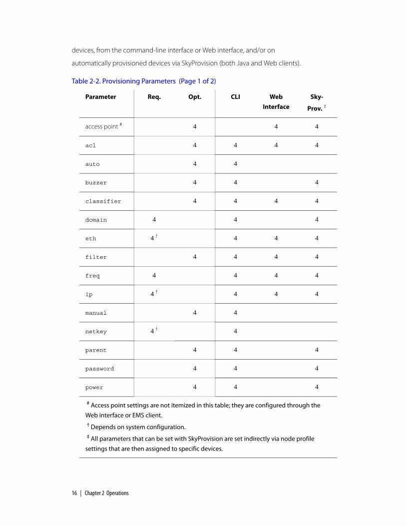
16 | Chapter 2 Operations
devices, from the command-line interface or Web interface, and/or on
automatically provisioned devices via SkyProvision (both Java and Web clients).
Table 2-2. Provisioning Parameters (Page 1 of 2)
Parameter Req. Opt. CLI Web
Interface
Sky-
Prov. ‡
access point # 4 4 4
acl 4 4 4 4
auto 4 4
buzzer 4 4 4
classifier 4 4 4 4
domain 4 4 4
eth 4 † 4 4 4
filter 4 4 4 4
freq 4 4 4 4
ip 4 † 4 4 4
manual 4 4
netkey 4 † 4
parent 4 4 4
password 4 4 4
power 4 4 4
# Access point settings are not itemized in this table; they are configured through the
Web interface or EMS client.† Depends on system configuration.‡ All parameters that can be set with SkyProvision are set indirectly via node profile
settings that are then assigned to specific devices.

Required Provisioning Parameters | 17
Required Provisioning ParametersRegardless of which provisioning mode you configure for a SkyGateway, the
device must have the frequency and domain parameters set before it can be
operational, as described in the next two sections.
In addition, if you’re planning to operate a SkyPilot device as a manually
provisioned device, you must change its provisioning mode from the default
(automatic) to manual.
Depending on your deployment, you may need to configure additional
provisioning parameters:
If virtual local area networks (VLANs) are being used in the wired network to
which the SkyGateway will connect, you may need to configure the
management VLAN parameters for the SkyGateway. See “Virtual Local Area
Networks (VLANs)” on page 20.
radar 4 4 4
snmp 4 4 4 4
timezone 4 4 4
trafficrate 4 4 4 4
vlan 4 † 4 4 4
web 4 4 4
Table 2-2. Provisioning Parameters (Page 2 of 2)
Parameter Req. Opt. CLI Web
Interface
Sky-
Prov. ‡
# Access point settings are not itemized in this table; they are configured through the
Web interface or EMS client.† Depends on system configuration.‡ All parameters that can be set with SkyProvision are set indirectly via node profile
settings that are then assigned to specific devices.

18 | Chapter 2 Operations
If the SkyPilot device’s Ethernet interface is configured to autonegotiate but
the device fails to negotiate Ethernet connectivity (possibly because the
device doesn’t support autonegotiation), you may need to configure the
Ethernet interface for a fixed speed and duplexity. See “Ethernet Interface” on
page 22.
If the network is using a nonstandard netkey (that is, anything other than the
default netkey, SkyPilot Network, Inc.), you need to set the device’s
netkey to match the other devices. Refer to the set netkey command,
described in the SkyPilot Command-Line Interface Reference. (The netkey can’t
be changed using SkyProvision or the Web interface.)
Although not required by SkyPilot devices in order to forward end-user data,
you should configure the IP address information so that you can access and
manage the device itself. See “Managing IP Addresses” on page 77.
Frequency
In order for devices within a SkyPilot network to form links, they must operate on
the same frequency. You can configure a variety of frequency settings, including
the primary (preferred) frequency, multiple allowed frequencies, and the dwell
time a device waits on its primary frequency before attempting to use a frequency
from its Allow list to achieve successful communications with network nodes.
Which frequencies you can set depends on the device:
For a SkyGateway, you can set the frequency over which it will be
broadcasting. (This is the primary frequency; the Allow list is ignored.)
For SkyExtenders and SkyConnectors, you can set the primary frequency, as
well as the range of frequencies that the device is allowed to use in its hunting.
SkyExtenders and SkyConnectors dwell on the primary frequency longer than
frequencies in their Allow list.
For automatically provisioned devices, you modify the frequency settings in the
node profile that’s assigned to the device (see “Access Point SkyAccess Profile
Elements” on page 132).
For manually provisioned devices, you set the frequency by using the
set prov freq command, described in the SkyPilot Command-Line Interface
Reference.

Required Provisioning Parameters | 19
Domains
A single domain can be defined to encompass your entire SkyPilot network,
including all its nodes. Or domains can be used to segregate a network into two or
more smaller networks, where each smaller network has the same characteristics
as the larger network: one or more SkyGateways, any number of SkyConnectors
(including none), and any number of SkyExtenders (including none).
A SkyConnector or SkyExtender can be configured to belong to a single domain
or all domains (the default). If configured for only a single domain, it can use any of
the SkyGateways within its domain, and it will choose the one with the lowest cost
route, taking into account the current link quality in both directions (upstream and
downstream), as well as the link quality further along the route to the ultimate
destination. The SkyConnector/SkyExtender cannot, however, form links with
SkyGateways outside its domain even if those SkyGateways are operating at a
frequency in the device’s Allow list. Conversely, if the SkyConnector/SkyExtender
belongs to all domains, it can join any device operating on an allowed frequency,
regardless of that device’s domain.
Typical domain configuration activities include:
Creating a domain for each SkyGateway and then load-balancing the
SkyConnectors across multiple SkyGateways (domains). In addition to
performance considerations, load balancing enables you to offer differentiated
services. For example, a smaller number of business users could be assigned to
one SkyGateway, while a larger number of residential users could be allocated
to a second SkyGateway.
Establishing domains with multiple SkyGateways that provide redundancy. In
this case, the SkyConnectors will select a SkyGateway based on cost route. If a
SkyGateway goes offline, the SkyConnectors using that SkyGateway
automatically select another SkyGateway within the same domain.
For automatically provisioned devices, you use the Domain Maintenance function
within SkyProvision to add, modify, and delete domains (see “Configuring

20 | Chapter 2 Operations
Domains” on page 124), and then you apply the domains to node profiles (see
“Access Point SkyAccess Profile Elements” on page 132).
For manually provisioned devices, you set the domain by using the
set prov domain command, described in the SkyPilot Command-Line Interface
Reference.
Virtual Local Area Networks (VLANs)
Virtual local area networks (VLANs) are portions of a network that are configured
as logical topologies defined by software, connected to the same physical
network infrastructure. Devices on separate VLANs of a network behave as if
they’re on physically separated networks. VLANs function by logically segmenting
the network into different broadcast domains so that packets are switched only
between ports that are designated for the same VLAN.
By enabling the following capabilities, VLANs offer significant benefits, such as
efficient bandwidth use, flexibility, performance, and security:
Restricting the dissemination of broadcast and node-to-node traffic, thereby
reducing the burden of extraneous network traffic.
Using standard router-based security measures (since all packets traveling
between VLANs must also pass through a router).
Segregating and switching ISP traffic. Wholesale operators can offer end users
a choice of any provider instead of only the provider operating a particular
network. In such cases, each SkyConnector would be assigned to a single ISP.
Additionally, end-user data can be separated by assigning VLANs to each
SkyExtender or SkyConnector’s Ethernet interface.
Isolating management traffic from user traffic. You can configure a
management VLAN, independent of a VLAN for end users. Management traffic
is thereby segmented and secure.

Required Provisioning Parameters | 21
There are two types of VLAN:
Management VLAN—Used to tag and strip data with a configured VLAN ID
as the data enters or exits the management interface of a device. In a SkyPilot
network, you configure the management VLAN only on the SkyGateway,
which then automatically propagates the VLAN configuration throughout the
network.
You must manually configure the SkyGateway VLAN because the VLAN tag
can affect whether the SkyGateway’s management traffic can reach a
provisioning server (the EMS server).
Data VLAN—Used to tag and strip data with a configured VLAN ID as the data
enters or exits the Ethernet interface of SkyExtenders and SkyConnectors. The
VLAN tag is added on a per-SkyExtender and per-SkyConnector basis.
The Ethernet interface of a SkyConnector or (non-DualBand) SkyExtender can be
configured to either a single VLAN or no VLAN. If it’s configured to a VLAN, all user
Ethernet traffic transmitted upstream by the SkyConnector or SkyExtender is
tagged with the configured VLAN ID. However, this VLAN tag is stripped from all
Ethernet packets sent from a local SkyConnector or SkyExtender 10/100bT
Ethernet interface. (Packets forwarded by the SkyGateway and SkyExtenders retain
the VLAN tag.)
Data VLANs should not be configured on the SkyExtender portion of a DualBand
or TriBand. Instead, VLANs can be configured on the access point’s WLAN. (See
“Access Point SSID Profiles” on page 42.)
TIP To avoid time-consuming troubleshooting, remember that once a SkyConnector or SkyExtender is configured to a VLAN, any packets received through their 10/100bT ports that contain a different VLAN tag are dropped. (In contrast, if a SkyConnector or SkyExtender is not configured to a VLAN, any tagged packets are forwarded unchanged.)
For automatically provisioned devices, you use SkyProvision to add, modify, and
delete VLANs (see “Configuring VLANs” on page 141).
For a manually provisioned device, you configure its VLAN by using the
command-line interface command (refer to the set prov vlan command,

22 | Chapter 2 Operations
described in the SkyPilot Command-Line Interface Reference) or its Web interface
counterpart (refer to the SkyPilot Web Interface Reference).
Ethernet Interface
A node’s 10/100bT Ethernet interface can be enabled or disabled; in addition its
physical settings can be configured for autonegotiation or set to full or half duplex,
and its speed can be set to 100 or 10.
NOTE This section does not apply to SkyExtender DualBands, which don’t have an Ethernet interface.
For SkyExtender-only applications (that is, where there is no subscriber interface),
if you do not plan to connect any devices to a SkyExtender’s Ethernet interface,
you may want to disable the Ethernet interface for security reasons.
For SkyConnector-only or combined applications (where a SkyExtender forms
wireless links to SkyConnectors and serves a local customer via the SkyExtender’s
Ethernet interface), you can selectively enable or disable the Ethernet interface to
control subscriber access.
For automatically provisioned devices, you use the Node Profile function within
SkyProvision to create profiles with the desired Ethernet interface status (see
“Access Point SkyAccess Profile Elements” on page 132), and then you apply the
node profiles to specific nodes (see “Configuring Nodes” on page 138).
For manually provisioned devices, you set the Ethernet interface status by using
the command-line interface command (refer to the set eth command,
described in the SkyPilot Command-Line Interface Reference) or its Web interface
counterpart (refer to the SkyPilot Web Interface Reference).

Optional Provisioning Parameters | 23
Optional Provisioning ParametersAs shown in Table 2-2 on page 16, most of the provisioning parameters are
optional—that is, you don’t have to set them in order for your SkyPilot network
devices to be operational. However, to fully utilize and customize SkyPilot
functions such as reporting, you’ll typically set many of the provisioning
parameters discussed in these sections:
“Radar Detection” on page 23
“SNMP” on page 25
“Time Zones” on page 26
“Quality of Service (QoS)” on page 27
“Filtering” on page 31
If SkyExtender DualBand/TriBand devices are being used, you may need to
configure their access points, including (possibly) the access points’ default
WPA-shared key, publicpublic. See “Access Points” on page 37.
You can find information about the remaining optional parameters listed in
Table 2-2 in the applicable reference appendices and guides:
Appendix B, “SkyProvision Reference”
Appendix D, “SkyControl Reference”
SkyPilot Command-Line Interface Reference
SkyPilot Web Interface Reference
Radar Detection
SkyPilot devices can be configured to detect radar transmission within their
reception range and take appropriate action if radar is detected. You configure
SkyGateways explicitly, which then propagate the setting to SkyExtenders and
SkyConnectors as links are formed.

24 | Chapter 2 Operations
Available configuration settings are:
Default—Depends on the region (identified by a communications governing
body) for which this device is manufactured:
FCC (US): default = Disable
ETSI (EU): default = Enable-shutdown
AUS-ACA (Australia): default = Disable
Public Safety (US/Latin America Public Safety): default = Disable
Disable—Disables radar transmission detection.
Enable-shutdown—Enables radar transmission detection, and takes
appropriate action, depending on device type, when radar is detected:
SkyGateways sever all links and then begin operating on the lowest frequency in the Allow list on which there’s been no radar detected, enabling links to reform on the network. The SkyGateway stays on the new channel indefinitely or until radar is detected.
SkyExtenders and SkyConnectors sever all links on the current operating frequency and begin searching on all other allowed frequencies for 30 minutes. If links are found on other frequencies, the device remains on that frequency until the links are severed or the device is restarted (even after the 30 minutes are up).
Enable-ignore—Enables radar transmission detection, and logs a message
whenever radar is detected.
For automatically provisioned SkyGateways, you use the Node Profile function
within SkyProvision to create profiles with the desired radar detection settings (see
“Access Point SkyAccess Profile Elements” on page 132), and then you apply the
node profiles to specific nodes (see “Configuring Nodes” on page 138).
For manually provisioned SkyGateways, you configure radar detection by using
the command-line interface command (refer to the set radar command,
described in the SkyPilot Command-Line Interface Reference) or its Web interface
counterpart (refer to the SkyPilot Web Interface Reference).
Optional Provisioning Parameters | 25
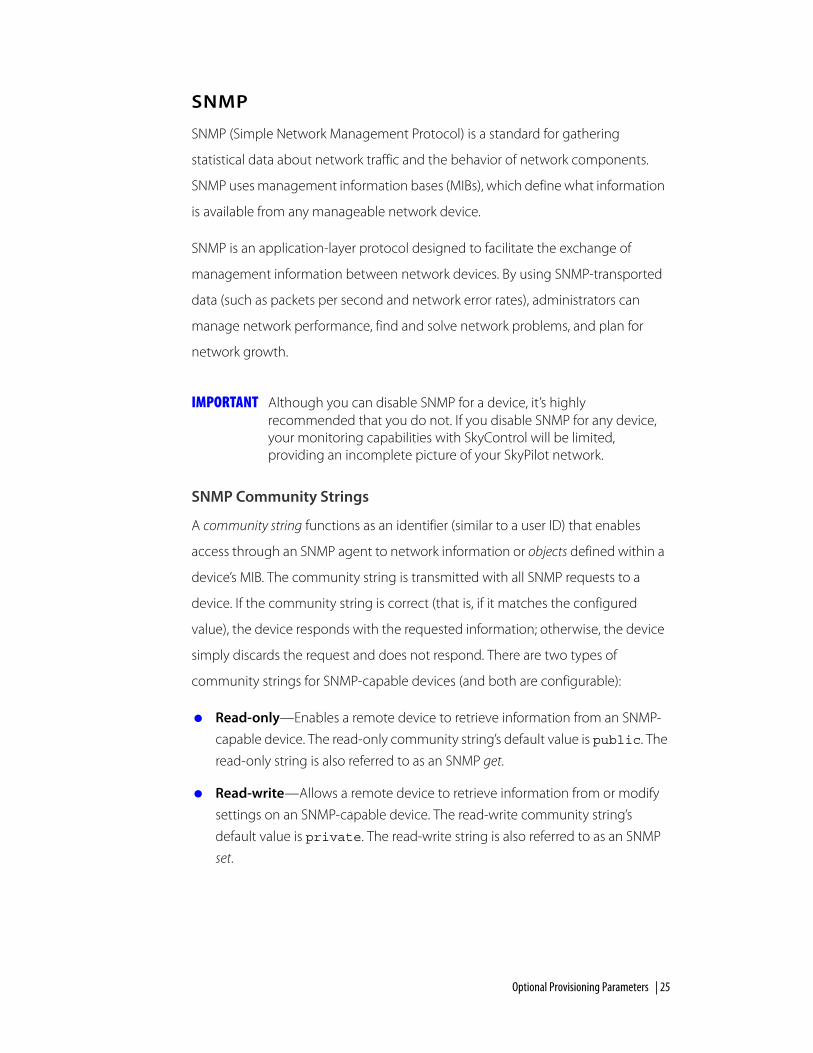
SNMP
SNMP (Simple Network Management Protocol) is a standard for gathering
statistical data about network traffic and the behavior of network components.
SNMP uses management information bases (MIBs), which define what information
is available from any manageable network device.
SNMP is an application-layer protocol designed to facilitate the exchange of
management information between network devices. By using SNMP-transported
data (such as packets per second and network error rates), administrators can
manage network performance, find and solve network problems, and plan for
network growth.
IMPORTANT Although you can disable SNMP for a device, it’s highly recommended that you do not. If you disable SNMP for any device, your monitoring capabilities with SkyControl will be limited, providing an incomplete picture of your SkyPilot network.
SNMP Community Strings
A community string functions as an identifier (similar to a user ID) that enables
access through an SNMP agent to network information or objects defined within a
device’s MIB. The community string is transmitted with all SNMP requests to a
device. If the community string is correct (that is, if it matches the configured
value), the device responds with the requested information; otherwise, the device
simply discards the request and does not respond. There are two types of
community strings for SNMP-capable devices (and both are configurable):
Read-only—Enables a remote device to retrieve information from an SNMP-
capable device. The read-only community string’s default value is public. The
read-only string is also referred to as an SNMP get.
Read-write—Allows a remote device to retrieve information from or modify
settings on an SNMP-capable device. The read-write community string’s
default value is private. The read-write string is also referred to as an SNMP
set.

26 | Chapter 2 Operations
SNMP Trap Receivers
SNMP trap receivers instruct a node where to send SNMP traps. To avoid a
negative impact on performance, SkyPilot recommends a maximum of 10 trap
receivers.
Applying SNMP Settings
You can create custom SNMP community strings and trap receivers; for details, see
“Configuring SNMP Parameters” on page 146.
For automatically provisioned devices, you use the Node Profile function within
SkyProvision to create profiles with the desired default or custom SNMP settings
(see “Access Point SkyAccess Profile Elements” on page 132), and then you apply
the node profiles to specific nodes (see “Configuring Nodes” on page 138).
For manually provisioned devices, you configure SNMP by using the command-
line interface command (refer to the set snmp command, described in the
SkyPilot Command-Line Interface Reference) or its Web interface counterpart (refer
to the SkyPilot Web Interface Reference).
Time Zones
You can specify an NTP (Network Time Protocol) server IP address and set the GMT
offset for accurate time. The NTP server provides the time to NTP clients (SkyPilot
nodes). When a SkyPilot node starts up, it has a default date and time of January 1,
1970, 00:00:00 GMT. Using an NTP server, the node adjusts its time to be
synchronized with the NTP server, which is usually UTC (Coordinated Universal
Time) or GMT.
SkyPilot equipment does not display the correct time until an NTP server is
specified. You must specify an NTP server in your DHCP configuration file and set
the time zone during provisioning (by setting the time zone in an automatically
provisioned node’s node profile, or by using command-line interface or Web
interface manual provisioning).
Optional Provisioning Parameters | 27
Quality of Service (QoS)
To maintain high QoS, the SkyPilot network implements a variety of controls:
Ingress rate control—The SkyPilot system offers support for operator-
configured maximum data rates in both directions: downstream (traffic going
to a subscriber) and upstream (traffic coming from a subscriber). The
SkyGateway controls the maximum downstream rate on a per-subscriber
basis, while the individual subscriber nodes control the maximum upstream
rate. This policing and shaping of traffic at the ingress points of the network
controls access to critical bandwidth resources and minimizes the QoS
mechanisms needed for traffic routed through the mesh network.
Scheduling fairness—To manage any shared-access system (including
broadband wireless) economically, a network operator must be able to
oversubscribe user data rates relative to the overall bandwidth of the system.
Therefore, there will likely be times when the overall demand is higher than
the available bandwidth. SkyGateway supports per-subscriber queuing in the
downstream direction, with queue control based on the configured maximum
downstream rate for each subscriber. These mechanisms ensure that each user
receives a proportionate share of available bandwidth during oversubscribed
periods.
Prioritization—SkyPilot software architecture allows for prioritization of data
based on protocol type, IP address, or other differentiators. This provides a
means of prioritizing the transmission of VoIP packets and any other type of
data.
Traffic rate controls—You can set traffic levels based on subscription rates.
For example, you could create a gold level for fastest service and a silver level
for slower service. The traffic levels are achieved by rate limiting. In
oversubscription conditions the data rates from subscribers may be reduced
proportionately. That is, a user with a 1 Mbps configured rate could be reduced
to 500 Kbps while a configured rate of 500 Kbps is reduced to 250 Kbps.
QoS classifiers—These are used to classify traffic according to the types of
packets that will be directed to a subscriber’s high-priority queue, for both
upstream and downstream traffic. All other traffic will be directed to the
subscriber’s standard (low-priority) queue.
For any given subscriber, this classification mechanism ensures that all queued
high-priority packets are transferred before any queued low-priority packets.

28 | Chapter 2 Operations
However, the system as a whole transfers packets based on traffic rate control
and fairness criteria, thus ensuring that the low-priority packets of one
subscriber will continue to flow even when high-priority packets are queued
for another subscriber.
NOTE You’re not required to configure traffic rate controls or QoS classifiers. By default (that is, with no QoS classifiers applied), there is no restriction on the maximum throughput, and no traffic priorities or classifications are observed.
Configuring QoS
For automatically provisioned devices, you use the QoS functions within
SkyProvision (see “Configuring QoS” on page 150).
For manually provisioned devices, you configure QoS by using command-line
interface commands (refer to the set trafficrate and set classifier
commands, described in the SkyPilot Command-Line Interface Reference) or their
Web interface counterparts (refer to the SkyPilot Web Interface Reference).
Traffic Rate Controls
Table 2-3 lists the elements that describe traffic rate controls.
Table 2-3. Traffic Rate Controls (Page 1 of 2)
Element Description
Name Name of the traffic rate control profile (unique among all such names), as a string of up to 64 alphanumeric characters. This name is used only within SkyProvision.
Upstream Rate (No effect on SkyGateways) Number from 64 to 10000, specifying upstream traffic rate (relative to the device using the profile) in kilobits per second; 0 to specify no traffic rate limit.
Downstream Rate
(No effect on SkyGateways) Number from 64 to 10000, specifying downstream traffic rate (relative to the device using the profile) in kilobits per second; 0 to specify no traffic rate limit.

Optional Provisioning Parameters | 29
QoS Classifiers
Table 2-4 lists the elements that describe QoS classifiers.
Broadcast Rate (SkyGateways only) Number from 64 to 10000, specifying the maximum downstream broadcast and multicast data rate in kilobits per second; 0 to specify no broadcast rate limit.
Date Created (Read-only) Date and time this traffic rate control record was created.
Date Modified (Read-only) Date and time this traffic rate control record was last modified.
Comment (Optional) Free-form text of up to 255 characters. This is not used by SkyProvision or SkyControl; it is for administrator reference only.
Table 2-4. QoS Classifiers (Page 1 of 3)
Element Description
Name Name of the QoS classifier (unique among all such names), as a string of up to 64 alphanumeric characters. This name is used only within SkyProvision.
IP TOS Low Along with IP TOS High and IP TOS Mask, matching parameters for the IP TOS (Type of Service) byte range and mask. An IP packet with IP TOS byte value ip-tos is considered a match if:
tos-low <= (ip-tos AND tos-mask) <= tos-high
If any of these fields is omitted, comparison of the IP packet TOS byte for this entry is irrelevant.
IP TOS High See IP TOS Low above.
IP TOS Mask See IP TOS Low above.
IP Protocol Protocol name, selected from the provided list.
Table 2-3. Traffic Rate Controls (Page 2 of 2)
Element Description

30 | Chapter 2 Operations
IP Protocol Number
(Read-only unless Other is selected as the IP Protocol) Protocol number. For the list of protocol type numbers, refer to the following IEEE Web page: http://standards.ieee.org/regauth/ethertype/eth.txt.
IP Source Address
Maximum of 12 digits in dotted notation.
IP Source Mask Maximum of 15 digits in dotted notation.
IP Destination Address
Maximum of 12 digits in dotted notation.
IP Destination Mask
Maximum of 15 digits in dotted notation.
TCP/UDP Source Port Start
Starting value for the source port as a number from 1 to 65535. The combination of IP address and port must be unique within all configured QoS classifiers.
TCP/UDP Source Port End
Ending value for the source port as a number from 1 to 65535. The combination of IP address and port must be unique within all configured QoS classifiers.
TCP/UDP Destination Port Start
Starting value for the destination port as a number from 1 to 65535. The combination of IP address and port must be unique within all configured QoS classifiers.
TCP/UDP Destination Port End
Ending value for the destination port as a number from 1 to 65535. The combination of IP address and port must be unique within all configured QoS classifiers.
Source MAC Address
Maximum of 12 digits in dotted notation.
Source MAC Address Mask
Maximum of 15 digits in dotted notation.
Destination MAC Address
Maximum of 12 digits in dotted notation.
Destination MAC Address Mask
Maximum of 15 digits in dotted notation.
Table 2-4. QoS Classifiers (Page 2 of 3)
Element Description

Optional Provisioning Parameters | 31
Filtering
Filters are used to control the transfer of user data packets through a SkyPilot
network. The filtering actions are performed on data packets received over the
SkyPilot device’s 10/100bT Ethernet interface. Four protocol fields can be
configured. Filtering to allow or deny packets is applied separately to these
protocol fields. If multiple filters are defined for a given protocol field, the filters are
performed in the order in which they’re listed in the SkyProvision display (for
devices in automatic provisioning mode) or in command-line interface output (for
devices in manual provisioning mode). The default filter is always applied last.
Ether Type Protocol of the traffic to filter, selected from the provided list.
Ether Type Number
(Read-only unless Other is selected as the Ether Type) Protocol number. For the list of protocol type numbers, refer to the following EEEE Web page: http://standards.ieee.org/regauth/ethertype/eth.txt
IEEE 802.1P User Priority Low
Lower limit of the range of the 801.1p flag in the TCP/IP header for which packets are forwarded instead of dropped, selected from provided list.
IEEE 802.1P User Priority High
Upper limit of the range of the 801.1p flag in the TCP/IP header for which packets are forwarded instead of dropped, selected from provided list.
Mesh Queue Priority
(Read-only) Priority level for mesh queue. Assigns priorities to packets that match the priority queue setting. Ranges from 1-High to 3-Low.
Date Created (Read-only) Date and time this QoS classifier record was created.
Date Modified (Read-only) Date and time this QoS classifier record was last modified.
Comment (Optional) Free-form text of up to 255 characters. This is not used by SkyProvision or SkyControl; it is for administrator reference only.
Table 2-4. QoS Classifiers (Page 3 of 3)
Element Description

32 | Chapter 2 Operations
Unlike access control lists, which examine data destined for a given SkyPilot node,
filters are used to filter all data passing through a given node.
You can configure filters for the following protocol fields:
Ethernet Type—Limits the traffic through a node to data of a specific
protocol type. EtherType values include the following (refer to the IEEE Web
page, http://standards.ieee.org/regauth/ethertype/eth.txt, for the current
complete list):
0x0800 IPv40x0806 RP0x809b AppleTalk over Ethernet0x8137 IPX0x8191 NetBIOS/NetBEUI0x86dd IPv6
IP Protocol—Limits the traffic through a node to IP data of a specific
subprotocol type. Subprotocol types include:
0x01 ICMP0x02 IGMP0x06 TCP0x11 UDP0x73 L2TP
IP Address—Limits the traffic through a node to data with specified source
and/or destination IP addresses.
Port—Limits the traffic through a node to data with a specified port number,
which generally identifies a subprotocol type. Valid port numbers include:
137-139 NetBIOS161-162 SNMP67 DHCP Client68 DHCP Server
Configuring Filters
For automatically provisioned devices, you configure filters by using SkyProvision
and selecting Enable in the Filter field of the node’s node profile. You must also
set the permission to Allow in the corresponding Filter field of the node’s node
profile. (For more information, see “Access Point SkyAccess Profile Elements” on
page 132.)

Optional Provisioning Parameters | 33
For manually provisioned devices, you configure filters by using the command-
line interface command (refer to the set filter command, described in the
SkyPilot Command-Line Interface Reference) or its Web interface counterpart (refer
to the SkyPilot Web Interface Reference).
EtherType Filters
Table 2-5 lists the elements that describe EtherType filter records.
Table 2-5. EtherType Filters
Element Description
Name Name of the EtherType filter (unique among all such names), as a string of up to 64 alphanumeric characters. This name is used only within SkyProvision.
Protocol EtherType protocol name allowed by this filter, selected from the provided list.
EtherType (Read-only unless Other is selected as the Protocol) EtherType value in hexadecimal. For the list of protocol type numbers, refer to the following IEEE Web page: http://standards.ieee.org/regauth/ethertype/eth.txt.
Permission (Default = Allow) Setting to allow or deny filtering of data that matches this filter’s criteria.
Date Created (Read-only) Date and time this filter record was created.
Date Modified (Read-only) Date and time this filter record was last modified.
Comment (Optional) Free-form text of up to 255 characters. This is not used by SkyProvision or SkyControl; it is for administrator reference only.

34 | Chapter 2 Operations
IP Protocol Filters
Table 2-6 lists the elements that describe IP protocol filter records.
Table 2-6. IP Protocol Filters
Element Description
Name Name of the IP protocol filter (unique among all such names), as a string of up to 64 alphanumeric characters. This name is used only within SkyProvision.
Protocol IP subprotocol allowed by this filter, selected from the provided list.
Protocol Number (Read-only unless Other is selected as the Protocol) Number of this filter’s protocol. For the list of protocol numbers, refer to the following IEEE Web page: http://www.iana.org/assignments/protocol-numbers.
Permission (Default = Allow) Setting to allow or deny filtering of data that matches this filter’s criteria.
Date Created (Read-only) Date and time this filter record was created.
Date Modified (Read-only) Date and time this filter record was last modified.
Comment (Optional) Free-form text of up to 255 characters. This is not used by SkyProvision or SkyControl; it is for administrator reference only.

Optional Provisioning Parameters | 35
IP Address Filters
Table 2-7 lists the elements that describe IP address filter records.
Table 2-7. IP Address Filters
Element Description
Name Name of the IP address filter (unique among all such names), as a string of up to 64 alphanumeric characters. This name is used only within SkyProvision.
IP Address IP address to compare to a packet’s source or destination address to determine how this filter is applied; up to 12 digits in dotted notation.
Subnet Mask Subnet mask used of the IP address group to compare to a packet’s source or destination address to determine how this filter is applied; up to 12 digits in dotted notation.
Type Packet data to which the IP Address and Subnet Mask fields are compared, specified as one of the following:
Destination—Packet destination address
Source—Packet destination address
ARP—Source IP address of an ARP request or response
Permission (Default = Allow) Setting to allow or deny filtering of data that matches this filter’s criteria.
Date Created (Read-only) Date and time this filter record was created.
Date Modified (Read-only) Date and time this filter record was last modified.
Comment (Optional) Free-form text of up to 255 characters. This is not used by SkyProvision or SkyControl; it is for administrator reference only.

36 | Chapter 2 Operations
Port Filters
Table 2-8 lists the elements that describe port filter records.
Table 2-8. Port Filters
Element Description
Name Name of the port filter (unique among all such names), as a string of up to 64 alphanumeric characters. This name is used only within SkyProvision.
Port Port number to compare to a packet’s source or destination port to determine how this filter is applied; a number from 1 to 65535.
Protocol (Default = TCP) Protocol allowed by this filter, selected from the provided list.
Type What the filter’s Port value is compared to, specified as follows:
Destination—Data packet’s destination port
Source—Data packet’s protocol source port
Permission (Default = Allow) Setting to allow or deny filtering of data that matches this filter’s criteria.
Date Created (Read-only) Date and time this filter record was created.
Date Modified (Read-only) Date and time this filter record was last modified.
Comment (Optional) Free-form text of up to 255 characters. This is not used by SkyProvision or SkyControl; it is for administrator reference only.

Optional Provisioning Parameters | 37
Access Points
SkyExtender DualBand/TriBand devices and SkyAccess DualBand devices
incorporate access points, which enable 802.11 network device communication.
Automatically provisioned DualBands and TriBands are assigned access point
profiles, which in turn are assigned an assortment of profiles as attributes, as
described in the following sections.
Wireless Local Area Networks
For every access point, you can define 16 distinct WLANs, which offers significant
benefits such as efficient bandwidth use, flexibility, performance, and security.
WLANs offer these benefits by enabling the following capabilities:
Restricting the dissemination of broadcast and node-to-node traffic, thereby
reducing the burden of extraneous network traffic.
Using standard router-based security measures.
Segregating and switching ISP traffic. Wholesale operators can offer end users
a choice of any provider instead of only the provider operating a particular
network. In such cases, each WLAN would be assigned to a single ISP.
Isolating management traffic from user traffic. You can configure a
management WLAN, independent of a WLAN for end users. Management
traffic is thereby segmented and secure.
Most WLAN deployments use one of two common types of WLAN configuration:
Open—Allows anyone with Wi-Fi capability to connect to the wireless
network via the SkyExtender DualBand/TriBand access point. An open WLAN
does not authenticate users at the network layer, nor does it depend on
authentication by a backend system.
An open configuration raises obvious security concerns. The lack of
encryption makes the network vulnerable to unauthorized access and
malicious actions (including denial-of-service attacks).
You can provide backend authentication at the application layer through a
captive portal mechanism operating outside your wireless mesh network. A
captive portal forces all HTTP traffic from an unauthenticated user to a login
Web page and blocks the traffic until the user successfully logs in. (For more

38 | Chapter 2 Operations
information about captive portal mechanisms, refer to the following Web
page: http://en.wikipedia.org/wiki/Captive_portal.)
An additional disadvantage of open configurations is that users must begin
each session from a Web browser before they can use other Internet
applications, such as email, ssh, ftp, and chat clients.
Protected—A Wi-Fi Protected Access (WPA) network, which uses standards-
based client authentication and encryption. Users may be authenticated via a
Radius server (which you’ll need to implement using a third-party solution).
WPA uses the IEEE 802.11b/g and IETF EAP protocols to give users a secure
connection with both the access point and the Radius server, allowing the
exchange of credentials (username@domain and password) and keys for
encrypting all traffic between the client and the access point—even after
authentication.
WPA encryption is by WEP, with the addition of keys that are unique to each
session and client. This additional keying mechanism eliminates the security
problems of the original WEP. You can use AES encryption with the
DualBand/TriBand for even stronger encryption capabilities.
(The access point’s default WPA-shared key is publicpublic).
WPA-shared key, publicpublic. For more information about WPA, refer to
the following Web page: http://en.wikipedia.org/wiki/Wi-
Fi_Protected_Access.
If you plan to configure a DualBand/TriBand access point for WPA operating
without a pre-shared key, you must configure a Radius server (see “Access
Point Radius Server Profiles” on page 40).
Configuring Access Points
For automatically provisioned devices, you modify the settings in the access point
profiles that are assigned to the device (see “Configuring Access Point Profiles” on
page 127).
For manually provisioned devices, you configure access points by using the Web
interface (refer to the SkyPilot Web Interface Reference).

Optional Provisioning Parameters | 39
Access Point Security Profiles
Table 2-9 lists the elements that describe access point security profiles.
Table 2-9. Access Point Security Profile Elements (Page 1 of 2)
Element Description
Name Name of the access point security profile (unique among all such names), as a string of up to 64 alphanumeric characters. This name is used only within SkyProvision.
Max Remote Login Sessions
(Optional) Maximum number of simultaneous remote Telnet or ssh sessions allowed, or 0 to specify unlimited sessions.
Max Remote Login Timeout
(Optional) Number of minutes a Telnet or ssh session stays connected without activity, or 0 to never time out.
Telnet Server Enables or disables the Telnet server for remote access to the access point’s command line.
Admin Telnet Password
(Optional) Password and user name for logging in to the Telnet server.
Peer to Peer Enables or disables peer-to-peer (blocks Layer 2 broadcast and ARP traffic between wireless clients).
Typically you’ll disable peer-to-peer in a public network if you want to prevent users from “sniffing” traffic or creating accidental “network neighborhoods” at the Ethernet or VLAN level. A private enterprise network may want to enable peer-to-peer to allow shared LAN services such as file sharing.
Management From Wireless Clients
Enables or disables wireless client access to the access point’s Web interface; if the check box is not selected, access is disabled (and the Web interface will be accessible only through the SkyPilot wireless mesh network).
Syslog Enables or disables system logging to a remote syslog server.
Syslog Server (Available only if Syslog is enabled) Syslog server’s IP address; maximum of 12 digits in dotted notation.
Syslog Port (Available only if Syslog is enabled; default = 514) Port for syslog server access.

40 | Chapter 2 Operations
Access Point Radius Server Profiles
If you plan to configure a DualBand/TriBand access point for WPA with password
authentication (instead of using pre-shared keys) you must configure a Radius
server with the following:
The IP address and shared secret of the access point.
EAP-PEAP/MSCHAPv2 and EAP-TTLS/PAP, or MSCHAPv2 (not EAP-TLS) suitable
for WPA. (Your Radius supplier can provide instructions.)
A Users database with user names and passwords. (You may also need to
identify a proxy Radius if you’re delegating some domains to other service
providers.)
Table 2-10 lists the elements that describe access point Radius server profiles.
Date Created (Read-only) Date and time this access point security profile record was created.
Date Modified (Read-only) Date and time this access point security profile record was last modified.
Comment (Optional) Free-form text of up to 255 characters. This is not used by SkyProvision or SkyControl; it is for administrator reference only.
Table 2-10. Access Point Radius Server Profile Elements (Page 1 of 2)
Element Description
Name Name of the access point Radius server profile (unique among all such names), as a string of up to 64 alphanumeric characters. This name is used only within SkyProvision.
Primary Host Primary Radius server’s IP address; maximum of 12 digits in dotted notation.
Primary Shared Secret
Shared secret string as specified in the primary Radius server’s client configuration.
Table 2-9. Access Point Security Profile Elements (Page 2 of 2)
Element Description

Optional Provisioning Parameters | 41
Primary Authentication Port
(Default = 1812) TCP/UDP port for primary Radius server authentication services; must match the port number configured for authentication on the primary Radius server.
Primary Accounting Port
(Default = 1813) TCP/UDP port for primary Radius server accounting services; must match the port number configured for accounting services on the primary Radius server.
Secondary Host (Optional) Same as Primary Host above, but for the secondary Radius server.
Secondary Shared Secret
(Available only if Secondary Host is configured) Same as Primary Shared Secret above, but for the secondary Radius server.
Secondary Authentication Port
(Available only if Secondary Host is configured) Same as Primary Authentication Port above, but for the secondary Radius server.
Secondary Accounting Port
(Available only if Secondary Host is configured) Same as Primary Accounting Port above, but for the secondary Radius server.
Date Created (Read-only) Date and time this access point Radius server profile record was created.
Date Modified (Read-only) Date and time this access point Radius server profile record was last modified.
Comment (Optional) Free-form text of up to 255 characters. This is not used by SkyProvision or SkyControl; it is for administrator reference only.
Table 2-10. Access Point Radius Server Profile Elements (Page 2 of 2)
Element Description

42 | Chapter 2 Operations
Access Point SSID Profiles
To accommodate the access point WLANs (see “Wireless Local Area Networks” on
page 37), each DualBand has 32 MAC addresses assigned to it, and each TriBand
has 64 MAC addresses. The MAC address of the SkyExtender’s 5 GHz radio (as seen
from the SkyGateway) is printed on the label affixed to the bottom of the
DualBand. MAC addresses are allocated as follows:
DualBand 2.4 GHz/TriBand 4.9 GHz access point is 1 less than the MAC address
of the 5 GHz radio.
TriBand 2.4 GHz access point is 33 less than the MAC address of the 5 GHz
radio minus 31.
DualBand 2.4 GHz WLAN BSSIDs begin with the MAC address of the 5 GHz
radio minus 31.
For example, if the MAC address of a DualBand is 000ADB01319F
(hexadecimal), the reserved addresses start at 000ADB013180.
TriBand 2.4 GHz WLAN BSSIDs begin with the MAC address of the 5 GHz radio
minus 63:
TriBand 4.9 GHz WLAN BSSIDs begin with the MAC address of the 5 GHz radio
minus 31.
For example, if the MAC address of a TriBand is 000ADB017A3F (hexadecimal),
the 2.4 GHz access point’s MAC address is 000ADB017A1E, and the reserved
addresses for the 2.4 GHz WLAN BSSIDs start at 000adb017a00. The 4.9 GHz
access point’s MAC address is 000ADB017A20, and the 4.9 GHz WLAN BSSIDs
start at 000ADB017A20.

Optional Provisioning Parameters | 43
Table 2-11 lists the elements that describe access point SSID profiles.
Table 2-11. Access Point SSID Profile Elements (Page 1 of 4)
Element Description
SSID Name of the access point SSID profile (unique among all such names), as a string of up to 64 alphanumeric characters. This name is used only within SkyProvision.
VLAN ID (Default = 0) Data VLAN ID mapped to this SSID, or 0 to indicate no VLAN assignment.
NOTE If you’re configuring this SSID for 802.1x or WPA, a Radius server can override the default VLAN setting on a per-user basis.
Broadcast SSID Enables or disables access point broadcasting of the SSID to 802.11 clients (making the SSID visible to users).
If Broadcast SSID is disabled, users can still associate with this SSID if they know the SSID and can configure their client software to connect to the SSID.
Typically, you’ll want to enable SSID broadcasting.
Prioritization Quality of Service (QoS) level.
The access point doesn’t enforce the selected QoS level; it simply sets the 802.1p tag for the selected level on all traffic that enters the SSID.
QoS choices correspond to 802.1p user priorities as follows:
Normal = 0
High = 6
SSID Status Enables or disables this SSID.
If SSID Status disabled, the SSID can still be fully configured, but the access point will not announce or respond to connection requests or other traffic directed to the SSID.

44 | Chapter 2 Operations
Security Policy Encryption and/or authentication scheme used by this SSID:
None—Open network (no authentication or encryption).
WEP—Static WEP; no authentication, shared WEP key, no key rotation, and WEP encryption.
Static WEP is easily cracked, and should not be used in production environments.
802.1x—802.1x/EAP authentication via dynamic WEP. The WEP key is unique per session and is automatically changed at a periodic rate via Radius reauthentication.
This is the preferred choice for older clients that do not support WPA.
WPA-TKIP—802.1x/EAP authentication via TKIP (Temporal Key Integrity Protocol), a hardened version of the older WEP standard. The key is updated automatically and transparently with DES or AES encryption.
This option provides higher security than WEP or 802.1x but requires users to have a WPA client (which is built into recent versions of Windows XP, Mac OS X, and Linux). WPA-TKIP can be configured to use Radius authentication or a pre-shared key.
WPA-AES:CCMP—Complete 802.11i (WPA2) standard, replacing WEP/DES and TKIP with a specific mode of the Advanced Encryption Standard (AES): the Counter Mode with Cipher Block Chaining-Message Authentication Code (CBC–MAC) Protocol (CCMP). CCMP provides both data confidentiality (encryption) and data integrity.
This is the highest security option you can choose, but some legacy 802.11 clients may not support it.
WEP Key Size (Available only if WEP is selected as the Security Policy) Key size to use for this network’s encryption: 40 bits or 104 bits (also known as 64-bit or 128-bit, respectively).
104 bits is preferred unless the SSID clients are unable to accept that setting.
WEP Allow Shared Key
(Available only if WEP is selected as the Security Policy) Enables or disables use of a pre-shared key.
WEP Encryption Key
(Available only if WEP is selected as the Security Policy) Text string that functions as a password; up to 255 printable characters.
Table 2-11. Access Point SSID Profile Elements (Page 2 of 4)
Element Description

Optional Provisioning Parameters | 45
802.1x Key Size (Available only if 802.1x is selected as the Security Policy) Key size to use for this network’s encryption: 40 bits or 104 bits (also known as 64-bit or 128-bit, respectively).
104 bits is preferred unless the SSID clients are unable to accept that setting.
802.1x Rekeying Period
(Available only if 802.1x is selected as the Security Policy) Number of seconds between dynamic key updates.
For maximum protection, enter 300 seconds (5 minutes) or less. Don’t use too small a value; rekeying requires about a second to complete, so too frequent rekeying can increase downtime.
WPA Pre-Shared Key
(Available only if WPA-TKIP or WPA-AES:CCMP is selected as the Security Policy) Enables or disables use of a pre-shared key.
WPA Passphrase (Available only if WPA-TKIP or WPA-AES:CCMP is selected as the Security Policy) Text string that functions as a password; up to 255 printable characters.
DHCP Server Type
Type of DHCP used by this SSID:
None—IP addresses can be supplied by a central DHCP server elsewhere on the network (typical setting).
Relay—DHCP requests on this SSID will be forwarded to the specified DHCP server.
Server—The access point acts as a DHCP server on the SSID.
DHCP Server IP Address
(Available only if Relay is selected as the DHCP Server Type) IP address of the authoritative DHCP server for a network.
DHCP IP Start Range
(Available only if Server is selected as the DHCP Server Type) Starting address for the IP address pool supplied by the DHCP server; for example, 192.168.10.100.
DHCP IP End Range
(Available only if Server is selected as the DHCP Server Type) Ending address for the IP address pool supplied by the DHCP server; for example, 192.168.10.254.
DHCP Subnet Mask
(Available only if Server is selected as the DHCP Server Type) Subnet mask for this network segment; for example, 255.255.255.0.
Table 2-11. Access Point SSID Profile Elements (Page 3 of 4)
Element Description

46 | Chapter 2 Operations
DHCP Gateway (Available only if Server is selected as the DHCP Server Type) IP address of the default gateway/router for this network segment.
DHCP DNS 1 (Available only if Server is selected as the DHCP Server Type) IP address of the primary DNS resolver for this network.
DHCP DNS 2 (Available only if Server is selected as the DHCP Server Type) IP address of the secondary DNS resolver for this network.
DHCP DNS 3 (Available only if Server is selected as the DHCP Server Type) IP address of the tertiary DNS resolver for this network.
DHCP Domain (Available only if Server is selected as the DHCP Server Type) Default domain name for this network.
DHCP Lease Time
(Available only if Server is selected as the DHCP Server Type) Number of seconds each DHCP lease remains valid before renewal is necessary.
Date Created (Read-only) Date and time this access point SSID profile record was created.
Date Modified (Read-only) Date and time this access point SSID profile record was last modified.
Comment (Optional) Free-form text of up to 255 characters. This is not used by SkyProvision or SkyControl; it is for administrator reference only.
Table 2-11. Access Point SSID Profile Elements (Page 4 of 4)
Element Description

Optional Provisioning Parameters | 47
Wi-Fi Multimedia AP Profiles
To ensure Quality of Service on SkyAccess access point WLANs (see “Wireless Local
Area Networks” on page 37), SkyPilot Networks EMS supports the creation of Wi-Fi
Multimedia AP profiles that let you provision limits on multimedia bandwidth use
on your access points.
Table 2-12 lists the elements that describe Wi-Fi Multimedia AP profiles.
Table 2-12. Wi-Fi Multimedia AP Profile Elements (Page 1 of 3)
Element Description
Name Name of the Wi-Fi Multimedia AP profile (unique among all such names), as a string of up to 64 alphanumeric characters. This name is used only within SkyProvision.
Voice CWMin A Contention Window (CW) value that species the minimum amount of time an endpoint must wait before attempting to transmit a voice packet.
Voice CWMax A Contention Window (CW) value that species the maximum amount of time an endpoint must wait before attempting to transmit a voice packet.
Voice AIFS Arbitrary InterFrame Space (AIFS) value that can improve voice performance under heavy loads.
Voice TxopLimit A Transmission Opportunity (Txop) value that specifies the channel holding times of contending stations in the presence of delay-sensitive voice traffic.
Voice ACM Enable or disable the use of an ACM wrapper filter to activate audio compression.
Voice ACK-POLICY
Enable or disable return of an acknowledge packet for every voice packet received. Enabling provides a more reliable transmission, but increases traffic load.
Video CWMin A Contention Window (CW) value that species the minimum amount of time an endpoint must wait before attempting to transmit a video packet.
Video CWMax A Contention Window (CW) value that species the maximum amount of time an endpoint must wait before attempting to transmit a video packet.
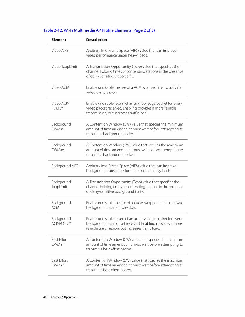
48 | Chapter 2 Operations
Video AIFS Arbitrary InterFrame Space (AIFS) value that can improve video performance under heavy loads.
Video TxopLimit A Transmission Opportunity (Txop) value that specifies the channel holding times of contending stations in the presence of delay-sensitive video traffic.
Video ACM Enable or disable the use of a ACM wrapper filter to activate video compression.
Video ACK-POLICY
Enable or disable return of an acknowledge packet for every video packet received. Enabling provides a more reliable transmission, but increases traffic load.
Background CWMin
A Contention Window (CW) value that species the minimum amount of time an endpoint must wait before attempting to transmit a background packet.
Background CWMax
A Contention Window (CW) value that species the maximum amount of time an endpoint must wait before attempting to transmit a background packet.
Background AIFS Arbitrary InterFrame Space (AIFS) value that can improve background transfer performance under heavy loads.
Background TxopLimit
A Transmission Opportunity (Txop) value that specifies the channel holding times of contending stations in the presence of delay-sensitive background traffic
Background ACM
Enable or disable the use of an ACM wrapper filter to activate background data compression.
Background ACK-POLICY
Enable or disable return of an acknowledge packet for every background data packet received. Enabling provides a more reliable transmission, but increases traffic load.
Best Effort CWMin
A Contention Window (CW) value that species the minimum amount of time an endpoint must wait before attempting to transmit a best effort packet.
Best Effort CWMax
A Contention Window (CW) value that species the maximum amount of time an endpoint must wait before attempting to transmit a best effort packet.
Table 2-12. Wi-Fi Multimedia AP Profile Elements (Page 2 of 3)
Element Description

Optional Provisioning Parameters | 49
Best Effort AIFS Arbitrary InterFrame Space (AIFS) value that can improve best effort transfer performance under heavy loads.
Best Effort TxopLimit
A Transmission Opportunity (Txop) value that specifies the channel holding times of contending stations in the presence of delay-sensitive best effort traffic.
Best Effort ACM Enable or disable the use of an ACM wrapper filter to activate best effort data compression.
Best Effort ACK-POLICY
Enable or disable return of an acknowledge packet for every best effort data packet received. Enabling provides a more reliable transmission, but increases traffic load.
Date Created (Read-only) Date and time this Wi-Fi Multimedia AP profile record was created.
Date Modified (Read-only) Date and time this Wi-Fi Multimedia AP profile record was last modified.
Comment (Optional) Free-form text of up to 255 characters. This is not used by SkyProvision or SkyControl; it is for administrator reference only.
Table 2-12. Wi-Fi Multimedia AP Profile Elements (Page 3 of 3)
Element Description

50 | Chapter 2 Operations
Wi-Fi Multimedia STA Profiles
To ensure Quality of Service for wireless clients connected to SkyAccess access
point WLANs (see “Wireless Local Area Networks” on page 37), SkyPilot Networks
EMS supports the creation of Wi-Fi STA profiles that allow you to provision
parameters for multimedia bandwidth use by wireless client devices.
Table 2-13 lists the elements that describe Wi-Fi Multimedia AP profiles.
Table 2-13. Wi-Fi Multimedia STA Profile Elements (Page 1 of 3)
Element Description
Name Name of the Wi-Fi Multimedia STA profile (unique among all such names), as a string of up to 64 alphanumeric characters. This name is used only within SkyProvision.
Voice CWMin A Contention Window (CW) value that species the minimum amount of time an endpoint must wait before attempting to transmit a voice packet.
Voice CWMax A Contention Window (CW) value that species the maximum amount of time an endpoint must wait before attempting to transmit a voice packet.
Voice AIFS Arbitrary InterFrame Space (AIFS) value that can improve voice performance under heavy loads.
Voice TxopLimit A Transmission Opportunity (Txop) value that specifies the channel holding times of contending stations in the presence of delay-sensitive voice traffic.
Voice ACM Enable or disable the use of an ACM wrapper filter to activate audio compression.
Voice ACK-POLICY
Enable or disable return of an acknowledge packet for every voice packet received. Enabling provides a more reliable transmission, but increases traffic load.
Video CWMin A Contention Window (CW) value that species the minimum amount of time an endpoint must wait before attempting to transmit a video packet.
Video CWMax A Contention Window (CW) value that species the maximum amount of time an endpoint must wait before attempting to transmit a video packet.

Optional Provisioning Parameters | 51
Video AIFS Arbitrary InterFrame Space (AIFS) value that can improve video performance under heavy loads.
Video TxopLimit A Transmission Opportunity (Txop) value that specifies the channel holding times of contending stations in the presence of delay-sensitive video traffic.
Video ACM Enable or disable the use of a ACM wrapper filter to activate video compression.
Video ACK-POLICY
Enable or disable return of an acknowledge packet for every video packet received. Enabling provides a more reliable transmission, but increases traffic load.
Background CWMin
A Contention Window (CW) value that species the minimum amount of time an endpoint must wait before attempting to transmit a background packet.
Background CWMax
A Contention Window (CW) value that species the maximum amount of time an endpoint must wait before attempting to transmit a background packet.
Background AIFS Arbitrary InterFrame Space (AIFS) value that can improve background transfer performance under heavy loads.
Background TxopLimit
A Transmission Opportunity (Txop) value that specifies the channel holding times of contending stations in the presence of delay-sensitive background traffic
Background ACM
Enable or disable the use of an ACM wrapper filter to activate background data compression.
Background ACK-POLICY
Enable or disable return of an acknowledge packet for every background data packet received. Enabling provides a more reliable transmission, but increases traffic load.
Best Effort CWMin
A Contention Window (CW) value that species the minimum amount of time an endpoint must wait before attempting to transmit a best effort packet.
Best Effort CWMax
A Contention Window (CW) value that species the maximum amount of time an endpoint must wait before attempting to transmit a best effort packet.
Table 2-13. Wi-Fi Multimedia STA Profile Elements (Page 2 of 3)
Element Description

52 | Chapter 2 Operations
Best Effort AIFS Arbitrary InterFrame Space (AIFS) value that can improve best effort transfer performance under heavy loads.
Best Effort TxopLimit
A Transmission Opportunity (Txop) value that specifies the channel holding times of contending stations in the presence of delay-sensitive best effort traffic.
Best Effort ACM Enable or disable the use of an ACM wrapper filter to activate best effort data compression.
Best Effort ACK-POLICY
Enable or disable return of an acknowledge packet for every best effort data packet received. Enabling provides a more reliable transmission, but increases traffic load.
Date Created (Read-only) Date and time this Wi-Fi Multimedia AP profile record was created.
Date Modified (Read-only) Date and time this Wi-Fi Multimedia AP profile record was last modified.
Comment (Optional) Free-form text of up to 255 characters. This is not used by SkyProvision or SkyControl; it is for administrator reference only.
Table 2-13. Wi-Fi Multimedia STA Profile Elements (Page 3 of 3)
Element Description

General Provisioning Guidelines | 53
General Provisioning GuidelinesSome requirements are independent of the provisioning mode you choose. To
ensure that network devices form effective links, always follow these guidelines:
Set the domain of SkyExtenders and SkyConnectors to match the domain
assigned to the SkyGateway, or to all domains.
To allow devices to establish network links more quickly, make sure that the
primary frequency of SkyExtenders and SkyConnectors is the same as the
primary frequency assigned to the SkyGateway.
Avoid adding unused frequencies to a device’s Allow list.
Make sure that the netkeys (shared network keys) match on all devices
attempting for form links. All SkyPilot devices ship with a same default public
netkey: SkyPilot Network, Inc.
Automatic ProvisioningAutomatically provisioned SkyPilot nodes use the parameters configured through
SkyProvision (a graphical interface that’s part of SkyPilot EMS). The parameter
settings are stored in a SkyPilot server’s database and are retrieved by devices
upon completion of the devices’ startup (for SkyGateway) or formation of links (for
SkyExtenders and SkyConnectors). Once the device receives its configuration
information from the server, the device is available to participate in the SkyPilot
network.
Automatically Provisioning All Network Devices
Table 2-14 summarizes the steps required to automatically provision all devices on
a network. Although SkyPilot devices can be provisioned in any order, by following
this sequence you can ensure that devices are able to form links as soon as they
come online.

54 | Chapter 2 Operations
Table 2-14. Automatically Provisioning All Network Devices (Page 1 of 2)
Step Refer to
1 For new SkyPilot network deployments, custom-install the operating system software on the SkyPilot EMS server.
The appropriate installation manual:
SkyPilot OS Installation: Red Hat Linux 9.0
SkyPilot OS Installation: Fedora Core 2 and 4
SkyPilot OS Installation: Red Hat Enterprise Linux ES 3 and 4
2 For new SkyPilot network deployments, install the server component of SkyPilot EMS, and then install the client component of SkyPilot EMS on any appropriate computer.
SkyPilot EMS Installation
3 For new SkyGateways, set up the DHCP server and, if the provisioning server is behind a firewall, open ports for data traffic between the server and SkyPilot devices.
“Adding Devices to the DHCP Configuration File” on page 77
“Configuring a Firewall for SkyPilot Operations” on page 195
4 Provision the SkyGateway(s).
“Automatically Provisioning a Device” on page 55
5 For new SkyGateways, complete the installation and power it on.
SkyGateway/SkyExtender Installation and Setup
6 (Optional) Log in to the SkyGateway and configure the management VLAN.
“Configuring VLANs” on page 141
7 Provision the SkyExtender(s).
“Automatically Provisioning a Device” on page 55

Automatic Provisioning | 55
Automatically Provisioning a Device
SkyPilot automatic device provisioning is a modular process whereby you use
SkyProvision to add specific configuration parameter building blocks to the
provisioning server’s database. Then you create a profile—a collection of
configuration parameters that can be assigned to multiple devices that require
the same parameter settings. This enables you to easily change a parameter
setting for every device that uses a common profile, just by changing the
parameter setting once in that profile. After a profile is changed, every device
inherits the change the next time the device requests its configuration.
Automatically provisioned devices receive their configuration from the
provisioning server (the EMS server) in the following situations:
Every time the device attempts to form a link
Every time the device reroutes
At an interval previously configured within the device’s configuration file
When the reload command is entered from the command line
When an SNMP write occurs on the device’s MIB reload variable
8 For DualBands and TriBands, provision the access point(s).
For information about access point settings, refer to SkyPilot Network Administration. For configuration procedures, refer to the SkyPilot Web Interface Reference
9 For new SkyExtenders, install the device and power it on.
SkyGateway/SkyExtender Installation and Setup
10 Provision the SkyConnector(s).
“Automatically Provisioning a Device” on page 55
11 For new SkyConnectors, install the device and power it on.
The appropriate installation manual:
SkyConnector Indoor Installation
SkyConnector Outdoor Installation
Table 2-14. Automatically Provisioning All Network Devices (Page 2 of 2)
Step Refer to

56
Table 2-15 describes the necessary steps to using SkyProvision to configure a
SkyPilot device for automatic provisioning.
Table 2-15. Automatically Provisioning a SkyPilot Device (Page 1 of 2)
Step Description Refer to
1 Make sure the most current software images are available in the EMS provisioning server’s /var/ftp/pub/images
directory.
2 Start the EMS Web or Java client.
“Logging in to the EMS Web Client” on page 117
“Starting the EMS Java Client” on page 102
3 Choose the software image the provisioning server will use to configure the new device.
“Managing Software Images” on page 64
4 For SkyGateways, assign a domain. If no domain exists, create one.
For other devices, specify a domain for the device that’s consistent with the domain assigned to the SkyGateway operating as a hub for the wireless mesh network.
“Configuring Domains” on page 124
5 (Optional) Configure a data VLAN to which the device can be assigned.
(Management VLANs are configured through a SkyGateway’s command-line interface.)
“Configuring VLANs” on page 141

Automatic Provisioning | 57
This table describes only those SkyProvision functions that are necessary for
enabling a device for automatic provisioning; you can perform many additional
functions using SkyProvision (see “Optional Provisioning Parameters” on page 23).
6 For DualBands/TriBands, confirm that appropriate access point profiles exist (including component security profiles).
If profiles don’t exist, create them in the following order:
Access point security profile
(For protected access networks, not open access networks) Access point Radius profile
Access point SSID profile
Access point profile(s)
“Configuring Access Point Profiles” on page 127
7 Confirm that an appropriate node profile exists for the device.
If no appropriate profile exists, create one.
“Access Point SkyAccess Profile Elements” on page 132
8 Add a node to the network for the device, assigning to it the appropriate node profile and attributes.
“Configuring Nodes” on page 138
9 Verify that the newly configured device has been successfully added as a node on the mesh network.
“Viewing Your SkyPilot Network” on page 182
10 (Optional) Set device polling intervals and other provisioning parameters.
Appendix B, “SkyProvision Reference”
Appendix D, “SkyControl Reference”
Table 2-15. Automatically Provisioning a SkyPilot Device (Page 2 of 2)
Step Description Refer to

58 | Chapter 2 Operations
Manual ProvisioningManually provisioned SkyPilot nodes use parameters configured through the
command-line interface or Web interface. The nodes store the parameter settings
in flash memory, where they remain available for recall when the device starts up.
Once the device starts up, it is operationally ready.
Assuming no security changes have been made that would affect the ability of
SkyPilot devices to proceed (such as netkey values or domain IDs), all SkyPilot
devices will discover and establish links with the wireless network without any
required commands, even in manual provisioning mode. However, the following
are exceptions that may require manual intervention on the part of the operator:
The SkyGateway must be configured with a primary transmit frequency, which
it will use to transmit data and establish links.
If your deployment uses a management VLAN, the VLAN must be manually
configured on the SkyGateway. This is necessary because a VLAN ID could
affect whether SkyPilot management traffic passes through the wired network
to which the SkyGateway is connected through its Ethernet interface.
If VLANs have been configured for end-user data in the wired network to
which the SkyGateway is connected through its Ethernet interface, VLANs
must be configured on all SkyExtender and SkyConnector devices in order for
end-user data to be appropriately tagged, sent, and received.
If netkeys have been changed on connected devices, the new netkey must be
manually configured on any device trying to join that network. This is
necessary because the netkey is the basis for determining whether a link is
trusted, which would make it impossible to rely on automated provisioning to
supply this parameter. If default netkeys are used, no change is necessary.
The remaining configuration settings are optional; they’re not required to be set in
order for a device to join the network and pass end-user data. Changes made
during manual provisioning are stored in flash memory, and therefore do not take
effect until the device is restarted.

Manual Provisioning | 59
Manual Provisioning Procedure
Table 2-16 summarizes the steps required to manually provision a device.
Table 2-16. Manually Provisioning a Device (Page 1 of 2)
Step Refer to
1 Decide whether to provision the device by using the command-line interface or the Web interface.
(For DualBand/TriBand access points, you must use the Web interface.)
“Choosing a Manual Provisioning Method” on page 60
2 If the device is not already installed in a SkyPilot network, prepare the device for installation by installing the necessary cabling and readying the device for service.
The appropriate installation manual:
SkyGateway/SkyExtender Installation and Setup
SkyConnector Indoor Installation
SkyConnector Outdoor Installation
3 Power on the device.
4 Connect a computer to the device and access the command-line interface or the Web interface.
(For DualBands/TriBands, this step refers to the SkyExtender portion of the device.)
SkyPilot Command-Line Interface Reference
SkyPilot Web Interface Reference
5 Provision the device, making sure to set at least the minimum provisioning parameters.
(For DualBands/TriBands, this step refers to the SkyExtender portion of the device.)
“Required Provisioning Parameters” on page 17 and either of the following:
SkyPilot Command-Line Interface Reference
SkyPilot Web Interface Reference
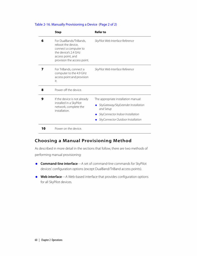
60 | Chapter 2 Operations
Choosing a Manual Provisioning Method
As described in more detail in the sections that follow, there are two methods of
performing manual provisioning:
Command-line interface—A set of command-line commands for SkyPilot
devices’ configuration options (except DualBand/TriBand access points).
Web interface—A Web-based interface that provides configuration options
for all SkyPilot devices.
6 For DualBands/TriBands, reboot the device, connect a computer to the device’s 2.4 GHz access point, and provision the access point.
SkyPilot Web Interface Reference
7 For TriBands, connect a computer to the 4.9 GHz access point and provision it.
SkyPilot Web Interface Reference
8 Power off the device.
9 If the device is not already installed in a SkyPilot network, complete the installation.
The appropriate installation manual:
SkyGateway/SkyExtender Installation and Setup
SkyConnector Indoor Installation
SkyConnector Outdoor Installation
10 Power on the device.
Table 2-16. Manually Provisioning a Device (Page 2 of 2)
Step Refer to

Manual Provisioning | 61
Command-Line Interface Provisioning
For manual provisioning, all SkyPilot devices (except the access point portion of
DualBands/TriBands) provide a command-line interface that allows you to interact
with the equipment through typed commands.
You can access the command-line interface by connecting a PC or laptop to the
device’s Ethernet interface (except for DualBands, which don’t have an Ethernet
interface) and using Telnet to start a communications session. The SkyGateway
and SkyExtender also include a serial port for connecting to a console via a serial
cable.
TIP The set prov command provides a convenient method for setting all the basic provisioning parameters for a device. This command queries you for all the provisioning parameters so that you don’t need to set each parameter individually. For more information, refer to the description of the set prov command in the SkyPilot Command-Line Interface Reference.
For details about accessing and using the command-line interface and a full
description of the command-line interface commands, refer to the SkyPilot
Command-Line Interface Reference.
Web Interface Provisioning
The Web interface provides two levels of access:
View-only level—Provides access to a single Web page displaying the current
operating status of a SkyPilot device.
Administrator level—Provides password-protected access to multiple pages
of content and a mechanism for modifying the configuration of the monitored
SkyPilot device.
The Web interface provides access to a manually provisioned DualBand/TriBand
access point as well as an easy alternative to the command-line interface for an
administrator to use to monitor and manage SkyPilot devices.
For details about accessing and using the Web interface and a full description of
its functions, refer to the SkyPilot Web Interface Reference.

62 | Chapter 2 Operations

SkyPilot Network Administration | 63
Administration
SkyPilot network administration involves routine management tasks, such as
managing software and customers, configuring security, and creating reports. This
chapter describes these management tasks and directs you to the corresponding
detailed procedures.
Chapter HighlightsManaging software images
Managing customers
Managing access control lists
About network security
About reports and statistics
3

64 | Chapter 3 Administration
Managing Software ImagesEvery SkyPilot device has two partitions (A and B) for storing software in flash
memory. At any given time, one partition (either A or B) is designated the active
partition, and the other partition is designated the backup partition.
Correspondingly, every SkyPilot device has two software images embedded in
flash memory:
Active image—The software image stored in the partition currently
designated the active partition. This image is used by a device when it starts
up.
Backup image—The software image stored in the partition currently
designated the backup partition. This image is used by a device if the active
image becomes unbootable (as explained below).
When a new software image is downloaded to a given partition, the image
previously in that partition is overwritten.
If you use SkyProvision to manage the software images, you simply specify the
name of the desired software image, and SkyProvision takes care of downloading
it to the proper partition and managing which partition is designated the active
partition.
If you’re manually managing the software images, you’ll specify which partition a
software image is downloaded into and then designate which partition to make
the active one (which implicitly designates the corresponding image as the active
image).
The device assigns every image a state:
Accepted—Either the image is known to be good (the device has successfully
formed links) or its state has been manually set to accepted (via the
set activeimage command, described in the SkyPilot Command-Line
Interface Reference).
Trial—The image has been successfully downloaded but has not yet been
used to form links.

Managing Software Images | 65
Unbootable—The image either was partially downloaded or was determined
during startup to be corrupt. (You can’t manually accept an unbootable
image.)
Nodes on a SkyPilot network are able to interoperate using different software
versions within the same major version release. For example:
Software versions 1.0.0 to 1.0.2p2 are all compatible with each other.
Software versions 1.1 through 1.1p2 are all compatible with each other.
Software versions 1.2 through 1.2p3 are all compatible with each other.
SkyPilot nodes use anonymous FTP to download new software images. The FTP
server therefore becomes the central repository of software images.
Configuring Software
For automatically provisioned devices, you use the Software Maintenance screen
within SkyProvision to browse and select software images from the FTP repository
(see “Configuring Software Images” on page 126) and then assign the image to a
node profile. (For more information about node profiles, see “Access Point
SkyAccess Profile Elements” on page 132.) You can also schedule a future software
version change by using the Software Schedule screen in SkyProvision.
For manually provisioned devices, you configure a device’s software by using the
command-line interface commands (refer to the ftpimage and
set activeimage commands, described in the SkyPilot Command-Line Interface
Reference) or their Web interface counterparts (refer to the SkyPilot Web Interface
Reference).

66 | Chapter 3 Administration
Software Maintenance Elements
Table 3-1 lists the elements that describe software maintenance records.
Software Schedule Elements
Table 3-1 lists the elements that describe software schedule records.
Table 3-1. Software Maintenance Elements
Element Description
Filename Software image file name, selected from a provided list that includes every SkyPilot software image in the EMS server’s /var/ftp/pub/images directory.
Date Created (Read-only) Date and time this software maintenance record was created.
Date Modified (Read-only) Date and time this software maintenance record was last modified.
Comment (Optional) Free-form text of up to 255 characters. This is not used by SkyProvision or SkyControl; it is for administrator reference only.
Table 3-2. Software Schedule Elements (Page 1 of 2)
Element Description
Name Name of the software schedule record (unique among all such names), as a string of up to 64 alphanumeric characters. This name is used only within SkyProvision.
Schedule Date Date on which the specified software will be downloaded, selected by clicking Calendar.
Status Activates or inactivates the scheduled software download.
Node Profile (Optional) Node profile(s) to which this software schedule is assigned; moved between the Select Node Profile and Selected Node Profile lists by using the desired direction’s move button (>> or <<).
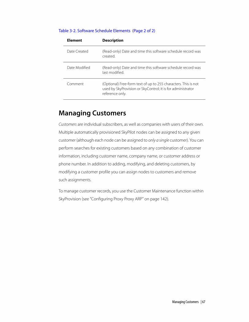
Managing Customers | 67
Managing CustomersCustomers are individual subscribers, as well as companies with users of their own.
Multiple automatically provisioned SkyPilot nodes can be assigned to any given
customer (although each node can be assigned to only a single customer). You can
perform searches for existing customers based on any combination of customer
information, including customer name, company name, or customer address or
phone number. In addition to adding, modifying, and deleting customers, by
modifying a customer profile you can assign nodes to customers and remove
such assignments.
To manage customer records, you use the Customer Maintenance function within
SkyProvision (see “Configuring Proxy Proxy ARP” on page 142).
Date Created (Read-only) Date and time this software schedule record was created.
Date Modified (Read-only) Date and time this software schedule record was last modified.
Comment (Optional) Free-form text of up to 255 characters. This is not used by SkyProvision or SkyControl; it is for administrator reference only.
Table 3-2. Software Schedule Elements (Page 2 of 2)
Element Description

68 | Chapter 3 Administration
Managing Access Control ListsAccess control lists (ACLs) enhance system security by controlling access to the
local management interface on a SkyPilot node port—for example, restricting
access to a given node to a specified set of management stations.
ACLs also can limit the number of management stations permitted to gain Telnet
access to a given node port. Management stations that are denied Telnet access
can still use SNMP to monitor a node’s status.
Unlike filters, which filter all data passing through a given SkyPilot node, ACLs
examine data destined for a given node.
By default (that is, if you do not configure ACLs), there are no restrictions to
accessing SkyPilot devices. To avoid a negative impact on performance, SkyPilot
recommends limiting the number of ACLs you configure to eight.
Configuring ACLs
For automatically provisioned devices, you use the Access Control List function
within SkyProvision (see “Configuring Access Control Lists” on page 149).
For a manually provisioned device, you configure its ACL by using the command-
line interface command (refer to the set acl command, described in the
SkyPilot Command-Line Interface Reference) or its Web interface counterpart (refer
to the SkyPilot Web Interface Reference).

About Network Security | 69
ACL Elements
Table 3-3 lists the elements that describe ACL records.
About Network SecurityThe SkyPilot Security Manager provides a complete set of network security
functions, including the capability to set up user profiles, to assign users to security
groups, and to configure which EMS functions users or groups can access.
For information about using the SkyPilot Security Manager, see “Managing
Network Security” on page 108.
Table 3-3. ACL Elements
Element Description
Name Name of the ACL list (unique among all such names), as a string of up to 64 alphanumeric characters. This name is used only within SkyProvision.
IP Address IP address from which this ACL allows access; up to 12 digits in dotted notation.
Subnet Mask Subnet mask used to allow a group of IP addresses to access a node; up to 12 digits in dotted notation.
Port Destination port through which access is granted; a number from 1 to 65535.
Protocol (Default = TCP) Protocol allowed by this ACL, selected from a provided list.
Date Created (Read-only) Date and time this ACL record was created.
Date Modified (Read-only) Date and time this ACL record was last modified.
Comment (Optional) Free-form text of up to 255 characters. This is not used by SkyProvision or SkyControl; it is for administrator reference only.

70 | Chapter 3 Administration
About Reports and StatisticsYou can use several closely related methods to view current and historical SkyPilot
device data. You can view the following:
Reports—Samples of collected data that are grouped into meaningful and
informative data sets presented in tabular format. Reports can be useful in
evaluating a particular device’s performance.
With SkyControl you can generate reports using data collected for the SkyPilot
MIB objects (see the next section). You can configure report parameters such
as the included objects, frequency of data collection, and report format.
SkyPilot EMS automatically builds any reports you configure, and you can view
them at any time.
NOTE Reports put less of a performance load on the EMS server than similar statistics functions, and so should be used whenever possible.
For procedures to configure, view, and purge reports, see “Using Reports” on
page 190.
Current statistics—A snapshot (that gets updated in real time) of MIB objects
selected from previously configured data collection tasks (see “Data Collection
Tasks” on page 71). Current statistics can be viewed in a variety of graphical
formats.
Collected statistics—A historical data view of MIB objects selected from
previously configured data collection tasks (see “Data Collection Tasks” on
page 71). Collected statistics can be viewed in a variety of graphical formats.
About the SkyPilot MIB
The SkyPilot MIB contains objects that have been configured to enable data
collection through collection tasks (both default and user-configured), as
described in this section. The collected information is used by SkyControl’s
reporting and system statistics functions.
The SkyPilot MIB is also the source of information for SkyPilot alarms (through
SNMP trap and performance threshold mechanisms).

About Reports and Statistics | 71
For the current MIB object definitions, refer to the spMib.txt file, located in the
/usr/local/skypilot/EMS/client/mibs directory.
WARNING Do not change the spMib.txt file. If you change this file and load it into a MIB browser, the SkyPilot nodes’ SNMP operations will not work properly, and SkyControl will not be able to perform its monitoring functions.
Data Collection Tasks
Data collection tasks collect data from the SkyPilot MIB for a specific device, at
defined intervals, for defined periods of time. The collected information is stored
on the EMS server, in its database.
When you add a device to your network, SkyPilot EMS automatically creates the
following data collection tasks for the device:
Status_Poll—Collects the device’s status. The default polling interval is 60
seconds, and you can change this interval from 1 second to hundreds of days.
You’ll gain network accuracy the smaller you make the interval, but values less
than 60 seconds can have an adverse effect on EMS performance.
Statistics—Collects an array of statistics for the device. The default polling
interval is 120 seconds, and you can change this interval from 1 second to
hundreds of days. You’ll gain accuracy the smaller you make the interval, but
values less than 120 seconds can have an adverse effect on EMS performance.
To modify the default data collection tasks or to configure custom tasks, you use
the device’s Configure Task function within SkyControl (see “Configuring Data
Collection Tasks” on page 187).
TIP If you know you’re not going to need a data collection task’s statistics for a while, you can stop it from running, which decreases the EMS server’s load and may improve performance. You can stop and start either of the device’s default data collection tasks as well as any custom tasks you’ve configured.

72

SkyPilot Network Administration | 73
Maintenance
SkyPilot maintenance tasks include developing monitoring and troubleshooting
strategies. This chapter describes techniques for maintaining your SkyPilot
network, as well as solutions to common troubleshooting issues.
Chapter HighlightsMonitoring a network’s topology with SkyControl
Monitoring events and alarms
Monitoring link states
Managing IP addresses
Using utilities
Troubleshooting
4

74 | Chapter 4 Maintenance
Monitoring a Network’s Topology with SkyControlSkyControl is SkyPilot’s customized SNMP management system for real-time
monitoring and management of automatically provisioned devices. One of
SkyControl’s unique features is that it provides a graphical view of your network
topology (including all network nodes and links) with at-a-glance updates on
topology, routing, and performance.
SkyControl’s SNMP implementation includes:
Default community strings—public (read-only) and private (read-write)
Support for the following standard MIBs:
MIB II
Ether-Like
Bridge
The private/enterprise SkyPilot MIB, which offers information about the
following SkyPilot hardware components and software elements:
Nodes—status, uptime, software/hardware version, and more
Links—state, RSSI, modulation, antenna, and more
Routing tables—forwarding, routing, MAC, and more
ACLs (access control lists)
Filters

Monitoring Events and Alarms | 75
Monitoring Events and AlarmsSkyPilot EMS includes comprehensive event and monitoring functions. SNMP
traps cause events, which in turn cause alarms based on default conditions and
custom-defined performance thresholds.
You can configure alarm levels, set up email notifications, generate reports, and
more. By monitoring alarms, you can take appropriate corrective action, as well as
prevent major network disruptions.
There are three types of SkyPilot alarm:
Polling alarm—The EMS server automatically polls every SkyPilot network
device, and can therefore report the following:
Agent down
Agent unreachable
IP conflict
SNMP trap alarm—An event reported by a device when it detects a value
change of a MIB object that’s been configured to generate traps. The SkyPilot
EMS includes a large set of preconfigured traps, and you can customize and
create additional traps corresponding to any MIB OID (organization ID); see
“Configuring Traps” on page 109.
In order for SNMP trap alarms to be generated, you need to configure the
following:
The corresponding EMS trap receivers (see “Configuring SNMP Parameters” on page 146)
The community string for notification, which must match the device’s hardcoded default community string, public (see “Configuring SNMP Parameters” on page 146)
The device’s SNMP community string and trap receiver attributes (select the device’s node profile and associate the desired attributes as described in “Node Profile Operations” on page 138)

76 | Chapter 4 Maintenance
Threshold alarm—An event triggered by SkyPilot EMS when it detects that a
MIB object’s value crosses a preconfigured threshold. For more information,
see “Configuring Threshold Alarms” on page 189.
For details about configuring, viewing, and annotating events and alarms, see
“Configuring Events” on page 112 and “Configuring Alarms” on page 113.
Monitoring Link StatesBy monitoring link states in your SkyPilot network, you can troubleshoot a variety
of provisioning and operational problems.
Table 4-1 describes the possible link states.
Table 4-1. Link States (Page 1 of 2)
State Description Firmware
version
act mgmt The link is to a child node and is active.
All
act path The link is the next hop to the gateway and is active.
All
standby The link is in standby state and is available for failover.
1.0.0 to 1.0.2p2
standby-o The link is in standby state and has been optimized.
1.1 and later
standby-h The link is in standby state but has not yet been optimized.
1.1 and later
inactive The link is currently inactive; there is no longer a connection.
All
non-opt The link is currently being optimized. All
pre-auth The link is being authorized and provisioned.
All
auth fail Authentication has failed (usually caused by incorrect netkeys).
All

Managing IP Addresses | 77
Managing IP AddressesAll SkyPilot devices ship with the default IP address 192.168.0.2, accessible only
from the Ethernet interface. A SkyGateway replaces this default when it receives a
new address through DHCP or if it’s explicitly configured with a static IP address.
However, SkyExtenders and SkyConnectors continue to keep this default IP
address available in addition to any IP address received through DHCP or static
configuration.
Adding Devices to the DHCP Configuration File
To enable automatic assignment of a fixed IP address to a SkyPilot device, you
must add the device to your DHCP server’s configuration by modifying the DHCP
configuration file.
To add a device to the DHCP server configuration:
1 Connect to the DHCP server using an SSH client, and log in as root.
2 Using any text editor, open the DHCP configuration file, dhcpd.conf (typically located in the /etc directory).
3 Using an existing entry as a model, add a new host entry for the device you plan to install, paying particular attention to the new node’s Ethernet MAC address.
prov fail Provisioning has failed due to DHCP failure or provisioning server failure.
All
parent A hello beacon has been received from a child node, and the connection is initiating.
All
child A hello beacon has been received from a parent node, and the connection is initiating.
All
Table 4-1. Link States (Page 2 of 2)
State Description Firmware
version

78 | Chapter 4 Maintenance
Your entry must be enclosed in the main subnet declaration where the TFTP, HTTP, and NTP server addresses are defined; if your entry is outside the subnet, it will not include (inherit) the required TFTP, HTTP, and NTP server addresses.
Entries look similar to the following:
host cpe0135 {hardware ethernet 00:0A:DB:00:01:35;fixed-address 192.168.6.118;option host-name "cpe0135";}
During SkyPilot EMS installation, default options that are inherited by all subsequent entries (such as the example above and your new entry) are added at the beginning of the DHCP configuration file.
4 Save your changes and close the file.
5 Refresh the DHCP server by entering the following command:
skypilot_dhcp_refresh
The response should look similar to the following:Shutting down dhcpd: [ OK ]Starting dhcpd: [ OK ]
6 Verify that the DHCP server restarts successfully.
You should see OK in the command output (as shown in the example in step 5), and you can monitor the startup messages (by using the tail -f /var/log/messages command) and watch for the Start up of dhcpd successful message.
Monitoring DHCP Activity
You can monitor the DHCP activity on your SkyPilot network by entering the
following command at a SkyPilot EMS terminal window:
tail -f /var/log/messages
To end DHCP monitoring, press CTRL+C.
Using Utilities | 79
The DHCP leases file, dhcpd.leases, is located in the /var/lib/dhcp/
directory, and can be viewed using more/vi/less.
Using UtilitiesSkyPilot devices include a number of built-in utilities to help with your
troubleshooting and maintenance tasks, as described in the following list:
Ping—Layer 3 ping utility
Node test—Two-way link layer ping test
Reboot—Device reboot
Traceroute—Path trace from the local node through the mesh network to the
SkyGateway
These utilities are available through the similarly named command-line command
(as described in the SkyPilot Command-Line Interface Reference) or through the
Web interface (refer to the SkyPilot Web Interface Reference).
TroubleshootingThis section presents procedures for troubleshooting problems of various kinds,
including startup and connectivity, with a SkyPilot device. Each procedure is
presented in a table set up like this (with varying numbers of steps and substeps).
1 You’ll be told to check for something as described in what follows:
a Here there will be a description of an action to take to accomplish the check.
Here you’ll see paragraphs describing what to do next, depending on the outcome of the action you took.
The following open-lock symbol is shown when you’ve solved the problem:
If advised to contact SkyPilot customer support, you can do so by email ([email protected]) or by telephone at (408) 764-8000.

80 | Chapter 4 Maintenance
For additional troubleshooting information, refer to the appropriate device
documentation or to the SkyPilot website at www.skypilot.com/support/.
This section makes numerous references to commands that are available through
the command-line interface; for details, refer to the SkyPilot Command-Line
Interface Reference.
The specific troubleshooting procedures are described in the following sections:
“Power-On Problems” (the next section)
“Ethernet Connectivity Problems” on page 82
“IP Connectivity Problems” on page 83
“SkyGateway Transmission Problems” on page 87
“Link Failure Problems” on page 89
Power-On Problems
Use the following procedure to troubleshoot the failure of a SkyPilot device to
power on. This procedure applies to any SkyPilot device and to either provisioning
mode (manual or automatic).
Table 4-2. Power-On Troubleshooting (Page 1 of 2)
1 Check whether the device is getting power:
a Verify that the device is plugged into an AC power supply.
If plugged in, go to substep b.
If not plugged in, plug in and restart.
b Test your power source with a voltage meter.
If power is available, go to step 2.
If power is not available, try an alternate power source and restart.
2 Check whether the power injector is OK:
Check whether the red light on the power injector is lit.
If the red light is lit, go to step 3.
If the red light is not lit, replace the power injector and restart.

Troubleshooting | 81
3 Check whether the device is properly cabled:
Verify that the device is connected to the power injector with a straight-through cable.
If the correct cable is being used, go to step 4.
If the wrong cable is connecting the device, replace it with the correct cable and restart.
4 Check whether the cable is defective:
Use a cable tester to check the cable.
If the cable is not defective, go to step 5.
If the cable is defective, replace it and restart.
5 Check whether the cable is plugged into the correct port:
On a SkyGateway or SkyExtender, confirm that the cable is plugged into the horizontal powered Ethernet interface and not the vertical serial port.
If the cable is plugged into the serial port, attach it to the powered Ethernet interface and restart.
If the cable is connected to the correct port on a SkyGateway or SkyExtender, or if the device is a SkyConnector, contact SkyPilot customer support.
Table 4-2. Power-On Troubleshooting (Page 2 of 2)

82 | Chapter 4 Maintenance
Ethernet Connectivity Problems
Use the following procedure to address problems that a SkyPilot device can have
in making Ethernet connections. This procedure applies to any SkyPilot device and
to either provisioning mode (manual or automatic).
Table 4-3. Ethernet Connectivity (Page 1 of 2)
1 Check whether the SkyPilot device is connected with the proper cables:
Verify the use of the following CAT5 twisted-pair cables:
Straight-through cable between power injector and the device
For SkyExtenders and SkyGateways: straight-through cable between power injector and an Ethernet switch or hub
For SkyExtenders and SkyGateways: crossover cable between power injector and computer
If the correct cables are being used, go to step 2.
If an incorrect cable is being used, replace it and restart.
2 Check whether any of the cables are defective:
Use a cable tester to check each cable connected to the device.
If none of the cables are defective, go to step 3.
If a cable is defective, replace it and restart.
3 Check whether Ethernet is enabled on all network devices connected to the SkyPilot device:
Confirm that Ethernet is enabled on all equipment connected to the SkyPilot device you’re troubleshooting.
If the Ethernet is enabled on all devices, go to step 4.

Troubleshooting | 83
IP Connectivity Problems
The primary causes of IP connectivity problems with SkyPilot devices are a failure
to acquire a GPS signal (in the case of a SkyGateway or SkyExtender), the location
of a device on the wrong subnet, and conflicts with VLAN management solutions.
This section addresses device problems related to IP connectivity. It includes the
following subsections:
“Manually Provisioned SkyGateway IP Connectivity Problems” (the next
section)
“Automatically Provisioned SkyGateway IP Connectivity Problems” on page 85
“SkyExtender and SkyConnector IP Connectivity Problems” on page 86 (applies
to both manual and automatic provisioning)
4 Check whether all of the connected devices are able to autonegotiate an Ethernet connection:
a Confirm that each network device is able to autonegotiate an Ethernet connection.
If all network device settings are correct go to substep b.
If the settings for any device are incorrect, modify its configuration and restart the device.
b To check the SkyPilot device, use the show eth command to view its current settings.
If the settings for the SkyPilot device are incorrect, use the set eth command to modify the Ethernet configuration, and then restart the device.
If the device settings are correct and the problem persists, contact SkyPilot customer support.
Table 4-3. Ethernet Connectivity (Page 2 of 2)

84 | Chapter 4 Maintenance
Manually Provisioned SkyGateway IP Connectivity Problems
Use the following procedure to troubleshoot IP connectivity problems with a
manually provisioned SkyGateway.
Table 4-4. Manually Provisioned SkyGateway Connectivity
1 Check whether the SkyGateway is able to acquire a GPS signal:
Log in to the SkyGateway via the serial port and observe the output at startup to verify the acquisition of a GPS signal.
Refer to “Accessing the Command-Line Interface” in the SkyPilot Command-Line Interface Reference for instructions on accessing the command-line interface of a SkyPilot device.
If the output confirms that the SkyGateway is receiving a GPS signal, go to step 2.
If the SkyGateway is failing to acquire a signal, move it to an alternate location and restart.
2 Check whether the SkyGateway is on the correct subnet:
Use the show prov command to verify that the SkyGateway is configured with the desired IP address.
If the command output shows the correct IP address, go to step 3.
If the output shows an incorrect IP address, use the set ip command to assign the correct IP address, and then restart the SkyGateway.
3 Check whether VLAN settings are preventing access to the SkyGateway:
Use the show vlan command to check whether a management VLAN is configured on the SkyGateway.
If the SkyGateway has been incorrectly configured with a management VLAN, modify (or remove) the VLAN with the set vlan command and restart.

Troubleshooting | 85
Automatically Provisioned SkyGateway IP Connectivity Problems
Use this procedure to troubleshoot IP connectivity problems with a SkyGateway
that’s provisioned automatically from the EMS server.
Table 4-5. Automatically Provisioned SkyGateway Connectivity
1 Check whether the SkyGateway is able to acquire a GPS signal:
Log in to the SkyGateway via the serial port and observe the output at startup to verify the acquisition of a GPS signal.
Refer to “Accessing the Command-Line Interface” in the SkyPilot Command-Line Interface Reference for instructions on accessing the command-line interface of a SkyPilot device.
If the output confirms that the SkyGateway is receiving a GPS signal, go to step 2.
If the SkyGateway is failing to acquire a signal, move it to an alternate location and restart.
2 Check whether VLAN settings are preventing access to the SkyGateway:
If a management VLAN is present, it might be preventing local access to the SkyGateway from the network.
Use the show vlan command to check whether a management VLAN is configured on the SkyGateway.
If the SkyGateway has been incorrectly configured with a management VLAN, modify (or remove) the VLAN with the set vlan command and retest.
If the VLAN settings are correct and the problem persists, contact SkyPilot customer support.
3 Check whether the SkyGateway is on the correct subnet:
Use the show dhcp command to verify that the SkyGateway received an IP address from DHCP. (A SkyGateway does not have a default IP address.)
If the command output shows that the SkyGateway did not get an IP address from DHCP or that it received an incorrect IP address, modify the configuration on the DHCP server and retest.
If the output shows that the SkyGateway has received an IP address from DHCP, contact SkyPilot customer support.

86 | Chapter 4 Maintenance
SkyExtender and SkyConnector IP Connectivity Problems
Use this procedure to troubleshoot IP connectivity problems with a SkyExtender
or SkyConnector (applies to both automatically and manually provisioned
devices).
Table 4-6. SkyExtender and SkyConnector Connectivity (Page 1 of 2)
1 (SkyExtender only) Check whether the device is able to acquire a GPS signal:
Log in to the SkyExtender via the serial port and observe the output at startup to verify the acquisition of a GPS signal.
Refer to “Accessing the Command-Line Interface” in the SkyPilot Command-Line Interface Reference for instructions on accessing the command-line interface of a SkyPilot device.
If the output confirms that the SkyExtender is receiving a GPS signal, go to step 2.
If the SkyExtender is failing to acquire a signal, move it to an alternate location and retest.
2 Check whether the computer is on the correct subnet:
To communicate over the LAN, the computer must be on the same subnet as the SkyPilot device.
Both SkyExtenders and SkyConnectors use the IP address 192.168.0.2.
Open the network settings panel of the computer to confirm that it’s using these settings:
IP address: 192.168.0.2
Subnet mask: 255.255.255.0
If the computer’s network settings are correct, go to step 3.
If the computer’s network settings are incorrect, apply the correct settings and retest.

Troubleshooting | 87
SkyGateway Transmission Problems
Use the procedures in this section to troubleshoot SkyGateway devices with
wireless transmission problems. There are two subsections, one for each type of
provisioning:
“Manually Provisioned SkyGateway Transmission Problems” (the next section)
“Automatically Provisioned SkyGateway Transmission Problems” on page 88
3 Check whether VLAN settings are preventing access to the device:
a If a management VLAN is present on the SkyGateway, it will prevent local network access to a SkyExtender or SkyConnector after the device forms a link with the SkyGateway.
On the SkyGateway, use the show vlan command to check whether a management VLAN is configured for that device.
If the SkyGateway has not been configured with a management VLAN, go to substep b.
If the SkyGateway has been configured with a management VLAN, modify (or remove) the VLAN with the set vlan command and retest.
b If a data VLAN is present on the SkyExtender or SkyConnector, it will prevent local network access to the device.
For a SkyExtender, log in to the device via the serial port; for a SkyConnector, log in via Telnet across the wireless network. Then use the show vlan command to check whether a data VLAN has been enabled on the device.
If the command output indicates that a data VLAN is present on the device, use the set vlan command to remove the VLAN, and then retest.
If the output does not indicate that a data VLAN is present and the problem persists, contact SkyPilot customer support.
Table 4-6. SkyExtender and SkyConnector Connectivity (Page 2 of 2)

88 | Chapter 4 Maintenance
Manually Provisioned SkyGateway Transmission Problems
Use this procedure to troubleshoot wireless transmission problems with a
manually provisioned SkyGateway (which immediately begins transmitting
network signals upon completing startup).
Automatically Provisioned SkyGateway Transmission Problems
Use this procedure to troubleshoot wireless transmission problems with a
SkyGateway that’s set up for automatic provisioning.
Table 4-7. Manually Provisioned SkyGateway Transmission
Check whether the SkyGateway is in manual provisioning mode:
Log in to the SkyGateway via the serial port and use the show prov command to confirm that the SkyGateway was placed in manual provisioning mode.
If the command output indicates that the device is not in manual provisioning mode, use the set prov manual command to set that mode, and then restart the SkyGateway. (After a SkyGateway is placed in manual provisioning mode, restarting it is necessary to activate the mode.)
If the SkyGateway is in manual provisioning mode but is unable to transmit signals, contact SkyPilot customer support.
Table 4-8. Automatically Provisioned SkyGateway Transmission (Page 1 of 2)
1 Check whether the SkyGateway is getting its IP settings from DHCP:
Log in to the SkyGateway via the serial port and use the show dhcp command to confirm that the SkyGateway received the correct IP settings, including IP address, subnet mask, default gateway, HTTP server (SkyProvision), and FTP server (SkyProvision).
If the command shows that the device received the correct IP settings, go to step 2.
If the device did not receive IP settings from DHCP or has incorrect settings, modify the configuration on the DHCP server and retest.

Troubleshooting | 89
Link Failure Problems
This section describes steps for troubleshooting all SkyPilot devices having
problems forming links that allow network communications. By branching off to
different subsections where applicable, this troubleshooting procedure applies to
both manually provisioned devices and devices set up for automatic provisioning
through SkyProvision.
2 Check whether the SkyGateway received a configuration file with correct settings:
A SkyGateway set up for automatic provisioning receives its configuration from the SkyProvision server.
Use the show config command to confirm that the device received correct configuration information, including the desired frequency and domain. If no settings are present, the SkyGateway did not receive a configuration file.
You can also review the contents of the /var/log/messages file on the SkyProvision server to verify that the SkyGateway is requesting a configuration and, if so, that SkyProvision is responding to the request.
If the command output indicates that the SkyGateway is not getting its configuration from SkyProvision or that it received incorrect settings, first confirm that the SkyProvision server is running. If it is, modify the configuration settings for the SkyGateway and retest.
If the output indicates that the SkyGateway is getting the correct configuration settings from the SkyProvision server, contact SkyPilot customer support.
Table 4-8. Automatically Provisioned SkyGateway Transmission (Page 2 of 2)

90 | Chapter 4 Maintenance
Failing to Form Links (General)
To troubleshoot problems that any SkyPilot device (whether provisioned manually
or automatically) may have in forming links that allow it to connect with other
devices on the wireless network, begin with the following steps.
Table 4-9. Link Formation Troubleshooting (General) (Page 1 of 5)
1 Check whether the device is listening on the desired frequency:
a Initially, a SkyPilot device scans for frequencies that are on its list of primary frequency or allowed frequencies.
Use the show prov freq command on the device to verify that the desired frequency is on the list. (You can also use this command on the SkyGateway to check the frequency.)
If the command output indicates that the desired frequency is on the list of primary or allowed frequencies, go to substep b.
If the desired frequency is not on the list, use the set freq command to specify the desired frequency as the device’s primary frequency, and then restart.
b Use the set log hello 3 and (Telnet only) debug on commands to observe frequency hunting in real time. The log will tell you whether the device is switching to the desired frequency.
Note that after attempting each allowed frequency twice, the device opens up to all frequencies.
If the log confirms that the device is switching to the desired frequency, go to step 2.
If the log does not show the device switching to the desired frequency, use the set freq command to specify the desired frequency as the primary frequency, and then restart.
2 Check whether the device is detecting signals from other devices:
a Use the show link command to find out whether the device is also receiving hello packets from a SkyGateway or SkyExtenders.
If the command output indicates that the device is not hearing a SkyGateway or any SkyExtenders, go to substep b.
If the output confirms that the device is hearing a SkyGateway or one or more SkyExtenders, go to step 3.

Troubleshooting | 91
b Use the set log hello 3 and (Telnet only) debug on commands to observe frequency hunting in real time.
The log will tell you whether the device is receiving hello packets from other devices when it switches to the desired frequency.
If the log indicates that the device is switching to the desired frequency but failing to receive hello packets, go to substep c.
If the log confirms that the device is switching to the desired frequency and also receiving hello packets from other devices, go to step 3.
c Adjust the device mount for improved signal reception and display the log again as in substep b.
If the log indicates that the device is still not receiving hello packets, try additional mounting points. If the device still fails to receive hello packets, go to substep d.
If the log confirms that the device is now receiving hello packets, secure the mount and restart the device.
d Move the device to an alternate site with proven coverage (for example, next to a connected device) and display the log again as in substep b.
If the log confirms that the device is now receiving hello packets, add an intermediary SkyExtender to improve signal coverage at the device’s original location.
If the log indicates that output is significantly less than shown by other devices operating at this location, contact SkyPilot customer support.
3 Check whether the device is failing to start optimization:
a Use the show link command to see if the MAC addresses heard by the device are remaining inactive. Look for evidence of link states that have changed from inactive to non-opt (non-optimized).
If the command output fails to show inactive links that have changed to the non-opt state, go to substep b.
If the output shows non-opt states, the device is starting link optimization. Go to step 4.
b Use the set log link 3 and (Telnet only) debug on commands to observe link state changes in real time. Look for link states that change from inactive to non-opt.
If the log fails to show inactive links changing to non-opt links, go to substep c.
If the log shows inactive links changing to non-opt links, the device is starting link optimization. Go to step 4.
Table 4-9. Link Formation Troubleshooting (General) (Page 2 of 5)

92 | Chapter 4 Maintenance
c Use the show link opt command to view a table displaying average RSSI and the number of hello packets the device is hearing. (The device will not attempt to optimize a link until it hears 5 packets.)
An RSSI value of less than 10 on the optimal antenna pair indicates a weak signal. An RSSI value of 20 or greater is preferred.
If the table shows a low RSSI value (less than 10), the signal is probably too weak for the device to attempt optimization. Go to substep d.
If the table indicates a threshold RSSI value (10 or greater), the signal should be strong enough for the device to attempt optimization. The problem is likely related to local radio interference, which can reduce the number of packets the device can hear. Monitor the area for sources of interference and retest.
d Adjust the device mount for improved signal reception and display the table again as in substep c.
If the table shows RSSI values less than 10, try additional mount adjustments. If the device continues to display RSSI values less than 10, go to substep e.
If the table shows that RSSI is now 10 or greater, secure the mount and restart the device.
e Move the device to an alternate site with demonstrated signal coverage (for example, next to a connected device) and display the table again as in substep c.
If the table shows RSSI values of 10 or greater, add an intermediary SkyExtender to improve signal coverage at the device’s original location.
If the table indicates that output is significantly lower than shown by other SkyPilot devices operating at this location, contact SkyPilot customer support.
4 Check whether the device is failing to complete link optimization:
a Use the show link command to see if the MAC addresses heard by the device have ever reached the pre-auth (pre-authorized) state, which indicates optimized links.
If the command output does not show pre-auth states, go to substep b.
If the output shows pre-auth states, the device is able to optimize links. Go to step 5.
b Use the set log link 3 and (Telnet only) debug on command to observe link state changes in real time. Look for link states that change from non-opt to pre-auth.
If the log fails to show non-opt links changing to pre-auth links, go to substep c.
If the log shows non-opt links changing to pre-auth links, the device is successfully optimizing links. Go to step 5.
Table 4-9. Link Formation Troubleshooting (General) (Page 3 of 5)

Troubleshooting | 93
c Use the show link opt command to view a table displaying average RSSI and the number of hello packets the device is hearing. (The device will not complete optimization of a link until it hears 5 packets.)
An RSSI value of less than 10 on the optimal antenna pair indicates a weak signal. An RSSI value of 20 or greater is preferred.
If the table shows a low RSSI value (less than 10), the signal is probably too weak for the device to attempt optimization. Go to substep d.
If the table indicates a threshold RSSI value (10 or greater), the signal should be strong enough for the device to complete optimization. The problem is likely related to local radio noise that’s interfering with SkyPilot signals. (Local radio interference on either side of a link can reduce the number of packets a device can hear, and prevent it from completing optimization.) Monitor the area for sources of interference and retest.
d Adjust the device mount for improved signal reception and display the table again as in substep c.
If the table shows RSSI values remaining below 10, try additional mount adjustments. If the device continues to display RSSI values less than 10, go to substep e.
If the table shows that RSSI is now 10 or greater, secure the mount and restart the device.
e Move the device to an alternate site with demonstrated signal coverage (for example, next to a connected device) and display the table again as in substep c.
If the table shows RSSI values of 10 or greater, add an intermediary SkyExtender to improve signal coverage at the device’s original location.
If the table indicates that output is significantly lower than shown by other SkyPilot devices operating at this location, contact SkyPilot customer support.
5 Check whether the device is authenticating links:
a Use the show link command to see if the MAC addresses heard by the device have ever reached the standby state, which indicates authorized links.
If authentication failures prevent link states from reaching standby, the states will return to auth-fail and inactive.
If the command output does not show standby states, go to substep b.
If the output shows standby states, the device is successfully forming links and is probably looking for alternates. Once the device exhausts attempts to form more links, it will choose an optimal standby link as the active path and come online.
Table 4-9. Link Formation Troubleshooting (General) (Page 4 of 5)

94 | Chapter 4 Maintenance
b Use the set log link 3 and (Telnet only) debug on commands to observe link state changes in real time. Look for link states that change from pre-auth to standby.
If the log fails to show pre-auth links changing to standby links, go to substep c.
If the log shows pre-auth links changing to standby links, the device is successfully forming links and is probably looking for alternates. Once the device exhausts attempts to form more links, it will choose an optimal standby link as the active path and come online.
c Use the set log auth 3 and (Telnet only) debug on commands to observe authentication events in real time. Look for reports of authentication failure due to timeouts or mismatched netkeys.
If the log reports any failure to authenticate due to timeouts or mismatched netkeys, go to substep d.
If the log reports successful authentication, the problem may be with provisioning. Go to step 6.
d Use the verifykey command to confirm the presence of a SkyPilot public/private key pair for the device.
If a public/private key pair exists, go to substep e.
If no keys exists, contact SkyPilot to obtain a public/private key pair.
e Use the show netkey command to confirm that the hashed equivalent of the netkey is identical to the value on all other connected devices.
Mismatched keys will cause authentication to fail.
If the netkeys do not match, use the set netkey command to modify the public key so that it matches the key used by other devices on the network. Restart the device.
If the netkeys match and the device continues to report authentication failures, contact SkyPilot customer support.
6 Continue this procedure with the steps in the next section for manually provisioned devices, or with the steps in “Failing to Form Links (Automatic Provisioning)” on page 96 for automatically provisioned devices.
Table 4-9. Link Formation Troubleshooting (General) (Page 5 of 5)

Troubleshooting | 95
Failing to Form Links (Manual Provisioning)
The following steps continue the general procedure in the preceding subsection
to address problems that manually provisioned SkyPilot devices may have in
forming links that allow it to connect with other devices on the wireless network.
Be sure to first perform the steps in that subsection (“Failing to Form Links
(General)” on page 90).
Table 4-10. Link Formation Troubleshooting (Manual Prov.) (Page 1 of 2)
7 Check whether the problem is related to a conflict due to configuration:
a Use the show link command to see if the MAC addresses heard by the device have ever reached the standby state.
If authentication is successful but link states fail to change from pre-auth to standby, they will return to prov-fail and eventually go back to inactive.
If the command output does not show standby states, go to substep b.
If the output shows standby states, the device is successfully forming links and is probably looking for alternates. Once the device exhausts attempts to form more links, it will choose an optimal standby link as the active path and come online.
b Use the set log link 3 and (Telnet only) debug on commands to observe link state changes in real time. Look for link states that change from pre-auth to standby.
If the log fails to show pre-auth links changing to standby links, go to substep c.
If the log shows pre-auth links changing to standby links, the device is successfully forming links and is probably looking for alternates. Once the device exhausts attempts to form more links, it will choose an optimal standby link as the active path and come online.

96 | Chapter 4 Maintenance
Failing to Form Links (Automatic Provisioning)
The following steps continue the general procedure in the subsection “Failing to
Form Links (General),” on page 90, to address problems that an automatically
provisioned SkyPilot device may have in forming links that allow it to connect with
other devices on the wireless network. Be sure to first perform the steps in the
earlier subsection.
c If the SkyGateway’s configuration parameters do not match the frequency or domain settings of the SkyGateway or SkyExtender it’s using to form links, devices will sever the links before connections can be made.
Use the show prov command to confirm that the SkyGateway’s configuration settings for frequency and/or domain match the frequency and/or domain it’s trying to use.
If the command output shows mismatched configuration information, modify the configuration to allow the SkyGateway’s frequency and/or domain and retest.
If the provisioning information matches the SkyGateway’s frequency and/or domain and the device is still reporting provisioning failures, contact SkyPilot customer support.
Table 4-11. Link Formation Troubleshooting (Automatic Prov.) (Page 1 of 4)
8 Check whether the device is failing to receive a configuration due to problems related to DHCP:
a Use the show link command to see if the MAC addresses heard by the device have ever reached the standby state, which indicates successful provisioning.
If authentication is successful but link states fail to change from pre-auth to standby, they will return to prov-fail and eventually go back to inactive.
If the command output does not show standby states, go to substep b.
If the output shows standby states, the device is successfully forming links and is probably looking for alternates. Once the device exhausts attempts to form more links, it will choose an optimal standby link as the active path and come online.
Table 4-10. Link Formation Troubleshooting (Manual Prov.) (Page 2 of 2)

Troubleshooting | 97
b Use the set log link 3 and (Telnet only) debug on commands to observe link state changes in real time. Look for link states that change from pre-auth to standby.
If the log fails to show pre-auth links changing to standby links, go to substep c.
If the log shows pre-auth links changing to standby links, the device is successfully forming links and is probably looking for alternates. Once the device exhausts attempts to form more links, it will choose an optimal standby link as the active path and come online.
c An incorrect DHCP configuration will prevent the device from obtaining its configuration from the provisioning server.
Use the show dhcp command to verify that the device is getting an IP address and other configuration information from the DHCP server.
If the command output indicates that the device received an IP address from the DHCP server, go to step 9.
If the command output indicates that the device is not getting an IP address from the DHCP server, or that it’s receiving incorrect information from the DHCP server, edit the DHCP content to include the correct information, and restart.
If the provisioning information matches the SkyGateway’s frequency and/or domain and the device is still reporting provisioning failures, contact SkyPilot customer support.
d Use the set log prov 3 and (Telnet only) debug on commands to observe provisioning events in real time. Monitor the DHCP server log to confirm that the device successfully made its request, and check the server’s response.
Note that if you’re using the ISC DHCP server, you can monitor server output in real time by monitoring the /var/log/messages file.
If the log indicates that the device received an IP address from the DHCP server, go to step 9.
If the log indicates that the device is not getting an IP address and other configuration information from the DHCP server, or that it’s receiving incorrect information from the DHCP server, edit the DHCP content to include the correct information, and restart.
Table 4-11. Link Formation Troubleshooting (Automatic Prov.) (Page 2 of 4)

98 | Chapter 4 Maintenance
9 Check whether the problem is related to unsuccessful provisioning:
a Use the show link command to see if the MAC addresses heard by the device have ever reached the standby state, which indicates successful provisioning.
If authentication is successful but link states fail to change from pre-auth to standby, they will return to prov-fail and eventually go back to inactive.
If the command output does not show standby states, go to substep b.
If the output shows standby states, the device is successfully forming links and is probably looking for alternates. Once the device exhausts attempts to form more links, it will choose an optimal standby link as the active path and come online.
b Use the set log link 3 and (Telnet only) debug on commands to observe link state changes in real time. Look for link states that change from pre-auth to standby.
If the log fails to show pre-auth links changing to standby links, go to substep c.
If the log shows pre-auth links changing to standby links, the device is successfully forming links and is probably looking for alternates. Once the device exhausts attempts to form more links, it will choose an optimal standby link as the active path and come online.
Table 4-11. Link Formation Troubleshooting (Automatic Prov.) (Page 3 of 4)

Troubleshooting | 99
c If the device’s configuration parameters do not match the frequency and/or domain settings of the SkyGateway or SkyExtender it’s using to form links, devices will sever the links before connections can be made.
Use the show config command to confirm that the device has completed provisioning, and to view configuration parameters.
If the command output does not show configuration parameters, SkyProvision may have no record of the SkyGateway. Go to substep d.
If the output shows mismatched configuration information, modify the configuration to allow the SkyGateway’s frequency or domain, and restart.
d Use the set log prov 3 and (Telnet only) debug on commands to observe provisioning events in real time. Look for reports of failure to download the device’s configuration file, or rejection of a link’s domain or frequency based on the contents of the device configuration.
Note that you can verify that SkyProvision is offering a configuration file by monitoring the /var/log/messages file, which contains a log of SkyProvision configuration transactions.
If the log reports failures related to the domain and frequency values stored in the device’s configuration file, edit the settings to include the correct values, and restart the device.
If the log does not report any offering of a configuration file, verify that the device’s information has been correctly added into SkyProvision, and restart.
If you confirm that the provisioning server is sending the correct configuration file to the device but the device continues to report that the file was not offered or that the device continues to sever links, contact SkyPilot customer support.
Table 4-11. Link Formation Troubleshooting (Automatic Prov.) (Page 4 of 4)

100

SkyPilot Network Administration | 101
General SkyPilot EMS Reference
SkyPilot EMS enables you to perform management and monitoring functions such as security configuration and alarm monitoring. This appendix provides detailed instructions for those functions.
Appendix HighlightsUsing SkyPilot EMS (Java client)
Managing network security
Configuring traps
Configuring performance thresholds
Configuring events
Configuring alarms
A

102 | Appendix A General SkyPilot EMS Reference
Using SkyPilot EMS (Java Client)SkyPilot EMS comprises applications from SkyPilot and third parties that enable
the automatic configuration and remote management of devices on the SkyPilot
network.
Starting the EMS Java Client
You can run multiple EMS Java clients on a single or multiple machines.
NOTE In addition to the following procedure, you may be able to start the EMS Java client by using the Start menu or desktop shortcuts that may have been set up during installation.
To start the SkyPilot EMS Java client:
1 Execute the SkyPilot EMS client startup script, SkyPilot\EMS\bin\startemsclient.bat (for Windows systems) or /usr/local/skypilot/EMS/bin/startsemsclient.sh (for Linux systems).
The Login window is displayed (Figure A-1).

Using SkyPilot EMS (Java Client) | 103
Figure A-1. SkyPilot EMS Login window
2 Enter your user name and password. The default user name is admin, and the default password is also admin.
3 Click Login.
The SkyPilot EMS Java client interface is displayed (see the next section).

104 | Appendix A General SkyPilot EMS Reference
The SkyPilot EMS Java Client Interface
Figure A-2 illustrates the SkyPilot EMS Java client interface.
Figure A-2. SkyPilot EMS Java client interface
The various parts of the interface are as follows:
Menu bar—Contains menus of commands that allow you to set global
network configuration items, as well as manage the windows in the display
pane.
Navigation pane—Contains a Windows Explorer–like hierarchical display of
the SkyPilot tools: SkyProvision and SkyControl.
Display pane—Shows the interface for the SkyPilot OAM tool selected in the
navigation pane. Multiple windows can be shown at one time in the display
pane.
Toolbar—Contains context-sensitive buttons used to manipulate objects in
the display pane, such as to lock a node’s position in a SkyControl domain
display. The toolbar buttons are enabled only when they’re applicable to the
display pane’s active window.
Alarm summary—Shows the number of active alarms for each alarm type:
critical, major, minor, and warning.
Alarm pane—Lists all active alarms.
Menu bar
Navigation pane
Display pane
Alarm summary
Alarm pane
Toolbar
Using SkyPilot EMS (Java Client) | 105
Stopping the EMS Java Client
You can stop the EMS Java client at any time without affecting your SkyPilot
network operations.
To stop the EMS Java Client:
1 From the menu bar, choose File ‰ Exit.
SkyProvision displays a Quit Confirmation message.
2 Click Yes.
Using the Menus
The EMS Java client menu bar contains menus of commands that allow you to set
global network configuration items, as well as manage the windows in the display
pane.
File Menu
The File menu lets you log out and return to the Login window (by choosing
File ‰ Exit) or end a SkyPilot EMS Java client session (by choosing File ‰ Exit).
View Menu
The View menu enables you to refresh the EMS Java client display (by choosing
View ‰ Refresh).
Object Menu
The Object menu changes its title and commands depending on which tool and
function you’ve selected in the navigation pane. For example, expanding the
SkyProvision tree in the navigation pane and clicking Customer Maintenance
causes the Object menu title to change to Customer Maintenance; similarly,
clicking VLAN in the SkyProvision tree causes the Object menu title to change
to VLAN.

106 | Appendix A General SkyPilot EMS Reference
Fault Menu
The Fault menu provides access to alarm maintenance, event log, and trap
functions. See “Configuring Traps” on page 109, “Configuring Events” on page 112,
and “Configuring Alarms” on page 113.
Performance Menu
The Performance menu provides access to global data collection and report
configuration functions. See “About Reports and Statistics” on page 70.
Security Menu
The Security menu enables you to manage network security (by choosing
Security ‰ Security Manager). See “Managing Network Security” on page 108.
Tools Menu
The Tools menu offers the following choices:
Look & Feel—To change the display pane appearance.
MIB Browser—To access the SkyPilot MIB, along with any other MIBs you’ve
installed. (This function requires prior installation of SkyControl, as well as the
appropriate SkyPilot EMS license.)
Telnet—To open a Telnet connection from your computer to any SkyPilot
device through a serial connection.
MAC Address Report—To create a report listing all MAC addresses that are
missing from node maintenance or SkyControl.
Alarm Color Settings—To change the colors used to indicate alarm severity
in the alarm summary and alarm pane.
Link Status Settings—To change the color and line style used to show link
status in SkyControl network displays.
Change Password—To change the password corresponding to the current
SkyPilot EMS Java client session’s user name.

Using SkyPilot EMS (Java Client) | 107
Window Menu
The Window menu provides standard Windows-based display options:
Cascade—To show all open display pane windows cascaded.
Tile Horizontal—To show all open display pane windows, tiled horizontally
(each sized to the display pane’s current width).
Tile Vertical—To show all open display pane windows, tiled vertically (each
sized to the display pane’s current height).
Minimize All—To minimize all open display pane windows.
Close All—To close all open display pane windows.
EMS-window—To make EMS-window the active display pane window.
Help Menu
The Help menu provides version and copyright information about the SkyPilot
EMS client (choose Help ‰ About).
NOTE Context-sensitive help information is available for every SkyProvision function. Click the Help action button from any display pane window (see “SkyProvision Display Pane” on page 120).

108 | Appendix A General SkyPilot EMS Reference
Managing Network SecuritySkyPilot EMS provides a complete set of network security functions, including the
capability to set up user profiles, to assign users to security groups, and to
configure which EMS functions users or groups can access.
NOTE The network security functions are accessible from the EMS Java client, but not the EMS Web client.
To access the security functions:
1 From the SkyPilot EMS Java client menu bar, choose Security ‰ Security Manager.
SkyPilot EMS displays the Security Manager screen (Figure A-3).
Figure A-3. Security Manager screen
2 Add, modify, or delete users or groups as desired.
3 Click Close.

Configuring Traps | 109
Configuring TrapsYou can modify trap descriptions, messages, and associated severity for both
preconfigured and custom traps by using the EMS trap parser.
To access the EMS trap parser:
1 From the SkyPilot EMS Java client menu bar, choose Fault ‰ Parser ‰ Trap Parser.
SkyPilot EMS displays the Incoming Trap Parser screen (Figure A-4).
Figure A-4. Incoming Trap Parser screen
2 Perform the desired operation:
To add a trap—Click New; click Add; enter a known MIB OID or choose Browse to select the OID from the MIB browser, and click OK; from the Event Details tab, set the elements using the desired token ($source, $community, or $uptime); enter the parser name; and click Apply.
To modify a trap—Select the desired trap in the Trap Parsers list and click Edit; then edit the desired elements and click Apply.
To delete a trap—Select the desired trap in the Trap Parsers list and click Delete; then click Yes.
3 Click Close.

110 | Appendix A General SkyPilot EMS Reference
Configuring Performance ThresholdsPerformance thresholds are severity level profiles that can be associated with MIB
objects for which data collection tasks are configured and alarms are generated.
So, for example, you can specify that when a MIB object’s value crosses a threshold
level, a threshold event will be generated and a corresponding alarm is created.
Performance Threshold Operations
1 From the SkyPilot EMS menu bar, choose Performance ‰ Configure Threshold.
SkyPilot EMS displays the Configure Threshold screen (Figure A-5).
Figure A-5. Configure Threshold screen

Configuring Performance Thresholds | 111
2 Click the name of the threshold whose settings you want to modify, and then click Edit.
SkyPilot EMS displays the threshold’s properties in the bottom part of the Configure Threshold screen (Figure A-5). Table A-1 lists the elements that describe performance thresholds.
3 Edit the threshold elements and click Save.
Focus returns to the Configure Threshold screen.
4 Click Close.
Table A-1. Performance Threshold Elements
Element Description
Name Name of the threshold (unique among all such names), as a string of up to 64 alphanumeric characters. This name is used only within SkyControl.
Type (Default = Decreasing) Direction of threshold object value change to monitor: Decreasing or Increasing.
Description (Optional) Free-form text of up to 255 characters. This is not used by SkyProvision or SkyControl; it is for administrator reference only.
Enable Enables or disables the performance threshold for the corresponding alarm severity.
Value Value at which the corresponding alarm is triggered.
Message Free-form text of up to 255 characters to display for the corresponding alarm trigger.

112 | Appendix A General SkyPilot EMS Reference
Configuring EventsYou can view, save, and print event logs, create event filters, and configure event
log purging from the Event Logs submenu of the EMS Java client Fault menu.
Figure A-6. EMS Event Logs submenu
Of particular interest are the following operations:
Refreshing event logs display—The View Logs display (shown by choosing
Fault ‰ Event Logs ‰ View Event Logs from the EMS Java client menu bar)
is a static snapshot of the event log as it exists when you first display it. To
refresh the display, select View ‰ Refresh from the View Logs toolbar or click
the View Logs display’s Refresh button, .
Managing log filters—From the Manage Log Filters display (Figure A-7, shown
by choosing Fault ‰ Event Logs ‰ Manage Event Log Filters from the EMS
Java client menu bar), you can add, modify, or delete filters that you can use to
view and print a defined subset of all events—for example, a filter to display
only events with a particular device name.
Figure A-7. Manage Log Filters display

Configuring Alarms | 113
Configuring AlarmsYou can manage alarms, create alarm filters, and configure alarm forwarding and
notification email from the Alarms submenu of the EMS Java client Fault menu.
Figure A-8. EMS Alarms submenu
Of particular interest are the following operations:
Viewing related events—From the alarms display (which is shown by choosing
Fault ‰ Alarms ‰ View Alarms from the EMS Java client menu bar), you can
display the list of related events for any single alarm by double-clicking
anywhere in the alarm line’s text.
Alarm trap forwarding—You can add, modify, and delete SNMP listeners for
alarm traps through the display shown in Figure A-9 (choose Fault ‰
Alarms ‰ Manage Alarm Trap Forwarding from the EMS Java client menu
bar).
Figure A-9. Adding an SNMP listener for alarm trap forwarding

114 | Appendix A General SkyPilot EMS Reference
Setting up email notifications—You can configure email notification to
automatically send email for selected alarms to selected recipients, by
configuring a mail server (choose Fault ‰ Alarms ‰ Mail Server
Configuration from the EMS menu bar) and managing the email notifications
through the display shown in Figure A-10 (choose Fault ‰ Alarms ‰
Manage Alarm Trap EMail Notification from the EMS Java client menu bar).
Figure A-10. Alarm EMail Notification display
SkyPilot Network Administration | 115
SkyProvision Reference
SkyProvision enables you to configure provisioning parameters for automatically provisioned devices and to perform administrative functions for your SkyPilot network. This appendix provides detailed instructions for using those provisioning and administrative functions through the SkyPilot EMS Java client.
Appendix HighlightsUsing SkyProvision
SkyPilot EMS Web client
Searching for provisioning objects
Configuring domains
Configuring software images
Configuring access point profiles
Configuring node profiles
Configuring nodes
Configuring VLANs
Configuring customers
Configuring SNMP parameters
Configuring access control lists
Configuring QoS
Configuring Web servers
B
116 | Appendix B SkyProvision Reference
Using SkyProvisionSkyProvision is a server-based application that automates device provisioning by
enabling devices to get their configuration information from the SkyPilot EMS
server.
IMPORTANT Although this appendix describes accessing SkyProvision from the EMS Java client, you can also access SkyProvision from the EMS Web client. The two clients provide identical functionality, except that the Web client’s node profile functions don’t provide a direct Detail viewing option. For information about accessing SkyProvision through the EMS Web client, see the next section.
SkyPilot EMS Web ClientThe EMS Web client is a Web-based application that is built into the EMS server
and can be accessed through a Web browser. This tool provides much the same
functionality as the SkyProvision portion of the EMS Java client, with the following
benefits:
Quicker response
No separate installation steps
The following section describes how to log into the EMS Web client. For detailed
information about the provisioning process and device configuration settings and
options, refer to the applicable sections of this document.

SkyPilot EMS Web Client | 117
Logging in to the EMS Web Client
To use the EMS Web client to provision SkyPilot devices, you must be able to
access the EMS server via a Web browser. You’ll need a user name and password in
addition to the EMS server’s IP address.
To log in to the EMS Web client:
1 Open a Web browser and enter the URL for the SkyPilot EMS server’s client login page: the server’s IP address or host name, preceded by http:// (for example, http://192.168.1.228).
The Web client displays a login screen (Figure B-1).
Figure B-1. EMS Web client login screen
2 Enter the user name and password. The default user name is admin, and the default password is also admin. Optionally, click Remember my User Name to enable this option.
3 Click Sign in.
The Web client displays its Welcome screen (Figure B-2). There’s also a navigation pane on the left, which contains a Windows Explorer–like hierarchy for navigating around in the Web client.
NOTE After 30 minutes of inactivity, the EMS Web client session expires, at which point you’ll need to repeat the login procedure to continue using SkyPilot EMS.

118 | Appendix B SkyProvision Reference
Figure B-2. Welcome screen
Starting SkyProvision (Java Client)
If SkyControl is already active, you don’t need to start another EMS Java client
session; both SkyProvision and SkyControl can be run within a single client session.
NOTE In addition to the following procedure, you may be able to start the EMS Java client by using the Start menu or desktop shortcuts that may have been set up during installation.
To access SkyProvision:
1 Execute the SkyPilot EMS Java client startup script, SkyPilot\EMS\bin\startemsclient.bat (for Windows systems) or /usr/local/skypilot/EMS/bin/startsemsclient.sh (for Linux systems).
The Login window (Figure B-3) is displayed.

SkyPilot EMS Web Client | 119
Figure B-3. SkyPilot EMS Java client Login window
2 Enter your user name and password. The default user name is admin, and the default password is also admin.
3 Click Login.
The SkyPilot EMS Java client interface is displayed (Figure B-4).
Figure B-4. SkyPilot EMS Java client interface
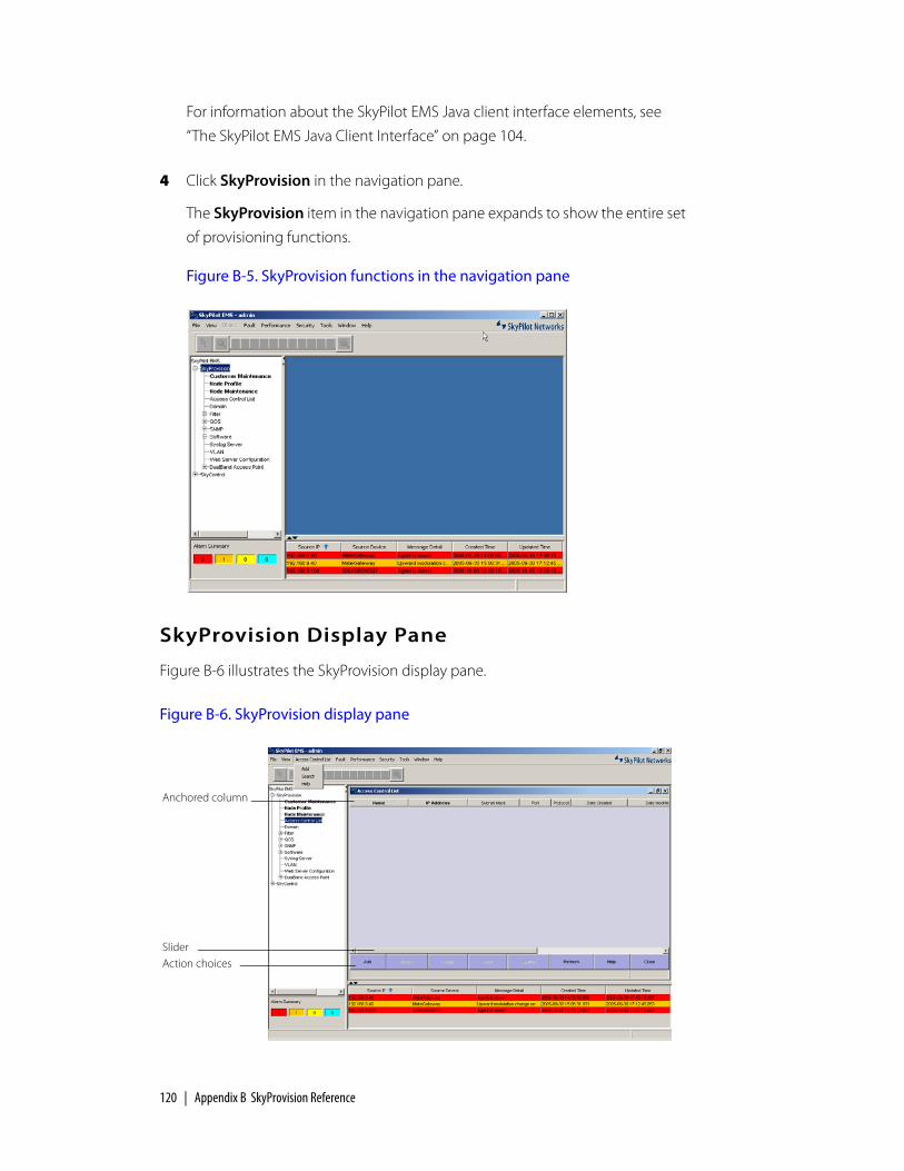
120 | Appendix B SkyProvision Reference
For information about the SkyPilot EMS Java client interface elements, see
“The SkyPilot EMS Java Client Interface” on page 104.
4 Click SkyProvision in the navigation pane.
The SkyProvision item in the navigation pane expands to show the entire set
of provisioning functions.
Figure B-5. SkyProvision functions in the navigation pane
SkyProvision Display Pane
Figure B-6 illustrates the SkyProvision display pane.
Figure B-6. SkyProvision display pane
Slider
Anchored column
Action choices

SkyPilot EMS Web Client | 121
The various parts of the interface are as follows:
Anchored columns—Columns that are not resizeable and that do not move
when you use the slider or arrows at the bottom of the display. Names of
anchored columns are indicated by bold text in the display pane.
Slider—The bar between the arrows just below the display. Use the slider to
move the non-anchored columns to the right and left so that you can see all
the information.
Action buttons—Context-sensitive buttons, such as Add, Refresh, Help, and
Close, that let you quickly perform common actions without using the menu
commands.
Typical Configuration Operations
There is a pattern to the way configuration operations are performed in
SkyProvision and how they’re described in the rest of this appendix. This section
explains the pattern; subsequent sections discuss the various configuration
operations in a concise way that provides any extra information you’ll need to
know once you’ve become familiar with the pattern.
Configuring Section
Each main provisioning topic begins with a Configuring section that introduces
what you’ll learn to configure—for example, “Configuring Domains” and “Access
Point SkyAccess Profile Elements.”
Elements Section
The first subsection within a Configuring section is typically an Elements section
that presents a table listing the elements related to the applicable configuration—
for example, “Domain Elements” presenting a table that lists elements such as
Name for the domain name, Domain for the domain ID, and so on. There may be
multiple Elements sections for closely related items. Alternatively, you may be
directed to an Elements section located elsewhere in this document.

122 | Appendix B SkyProvision Reference
Operations Section
Next, the Operations section uses a concise tabular presentation to show the
configuration operations and how to perform them, similar to Table B-1 for
domains.
To use one of these tables, first look in the Operation column to find the
operation you want to perform. If there are any lower-numbered steps, perform
their actions first, and then perform the desired operation’s actions. For example, if
you wanted to modify a domain, you’d perform the action for step 1 in Table B-1
and then the action for the Modify operation in step 2. Spelled out in full, the
procedure to modify a domain would be as follows:
1 If the Domain screen is not already showing in the display pane, expand the SkyProvision tree in the navigation pane and then double-click Domain under it.
SkyProvision displays the Domain screen (Figure B-7).
Table B-1. SkyProvision Configuration Operations Example Table
Operation From Actions
1 View Navigation pane SkyProvision ‰ Domain (double-click)
2 Add Menu bar Domain ‰ Add
Modify Display pane Domain name (right-click) ‰ Modify
Delete Display pane Domain name (right-click) ‰ Delete

SkyPilot EMS Web Client | 123
Figure B-7. Domain screen
2 In the display pane, right-click the name of the domain you want to modify and choose Modify.
3 Edit the domain elements.
4 Click OK.
You can see from Table B-1 that the actions you’d take to delete a domain would
be very similar to those in the procedure just described, as would the actions for
adding a domain (though in that case you’d use the menu bar instead of the
navigation pane).
Note that where a configuration procedure includes choosing a command from a
menu, you may be able to do so not only with the mouse but also with a keyboard
shortcut, with an action choice button below the display area of the display pane,
or from the navigation pane by double-clicking the desired item in the expanded
SkyProvision tree and selecting an item from the resulting screen in the display
pane.
Regardless of what you’re configuring, the operations will follow a similar pattern
to what’s shown in Table B-1, and where there are variations the table will use the
same notational conventions as in Table B-1.
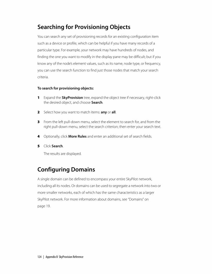
124 | Appendix B SkyProvision Reference
Searching for Provisioning ObjectsYou can search any set of provisioning records for an existing configuration item
such as a device or profile, which can be helpful if you have many records of a
particular type. For example, your network may have hundreds of nodes, and
finding the one you want to modify in the display pane may be difficult; but if you
know any of the node’s element values, such as its name, node type, or frequency,
you can use the search function to find just those nodes that match your search
criteria.
To search for provisioning objects:
1 Expand the SkyProvision tree, expand the object tree if necessary, right-click the desired object, and choose Search.
2 Select how you want to match items: any or all.
3 From the left pull-down menu, select the element to search for, and from the right pull-down menu, select the search criterion; then enter your search text.
4 Optionally, click More Rules and enter an additional set of search fields.
5 Click Search.
The results are displayed.
Configuring DomainsA single domain can be defined to encompass your entire SkyPilot network,
including all its nodes. Or domains can be used to segregate a network into two or
more smaller networks, each of which has the same characteristics as a larger
SkyPilot network. For more information about domains, see “Domains” on
page 19.

Configuring Domains | 125
Domain Elements
Table B-2 lists the elements that describe domains.
Domain Operations
Table B-3 lists the operations you can perform to configure domains.
Table B-2. Domain Elements
Element Description
Name Name of the domain (unique among all such names), as a string of up to 64 alphanumeric characters. This name is used only within SkyProvision.
Domain # Identification number from 1 to 10000 used by all nodes within a given domain.
Date Created (Read-only) Date and time this domain record was created.
Date Modified (Read-only) Date and time this domain record was last modified.
Comment (Optional) Free-form text of up to 255 characters. This is not used by SkyProvision or SkyControl; it is for administrator reference only.
Table B-3. Domain Operations
Operation From Actions
1 View Navigation pane SkyProvision ‰ Domain (double-click)
2 Add Menu bar Domain ‰ Add
Modify Display pane Domain name (right-click) ‰ Modify
Delete Display pane Domain name (right-click) ‰ Delete

126 | Appendix B SkyProvision Reference
Configuring Software ImagesSkyProvision allows you to manage software updates on your SkyPilot devices. (For
information about software images, see “Managing Software Images” on page 64.)
Software Image Operations
Table B-4 lists the operations you can perform to configure software images.
Software Schedule Operations
Table B-5 lists the operations you can perform to configure software schedules.
Table B-4. Software Image Operations
Operation From Actions
1 View Navigation pane SkyProvision ‰ Software ‰ Software Maintenance (double-click)
2 Add Menu bar Software Maintenance ‰ Add
Modify † Display pane Software image name (right-click) ‰ Modify
Delete Display pane Software image name (right-click) ‰ Delete
† The only element you can modify is the comment.
Table B-5. Software Schedule Operations
Operation From Actions
1 View Navigation pane SkyProvision ‰ Software ‰ Software Schedule (double-click)
2 Add Menu bar Software Schedule ‰ Add
Modify Display pane Software schedule name (right-click) ‰ Modify
Delete Display pane Software schedule name (right-click) ‰ Delete

Configuring Access Point Profiles | 127
Configuring Access Point ProfilesAccess point profiles are used to save settings that define a SkyExtender
DualBand/TriBand access point and that can be applied to multiple generic,
DualBand, and TriBand node profiles. Access point profiles are composed of the
following profiles: access point SkyAccess, access point security, access point
Radius (for protected networks), access point SSID, Wi-Fi multimedia AP, and Wi-Fi
multimedia STA.
For general access point information, see “Access Points” on page 37.
Access Point Security Profile Operations
Table B-6 lists the operations you can perform to configure access point security
profiles.
For element information, see “Access Point Security Profiles” on page 39.
Table B-6. Access Point Security Profile Operations
Operation From Actions
1 View Navigation pane SkyProvision ‰ Access Point ‰ Access Point Security Profile (double-click)
2 Add Menu bar Access Point Security Profile ‰ Add
Modify Display pane Profile name (right-click) ‰ Modify
Delete Display pane Profile name (right-click) ‰ Delete

128 | Appendix B SkyProvision Reference
Access Point Radius Profile Operations
Table B-7 lists the operations you can perform to configure access point Radius
profiles.
For element information, see See “Access Point Radius Server Profiles” on page 40.
Access Point SSID Profile Operations
Table B-8 lists the operations you can perform to configure access point SSID
profiles.
For element information, see See “Access Point SSID Profiles” on page 42.
Table B-7. Access Point Radius Profile Operations
Operation From Actions
1 View Navigation pane SkyProvision ‰ Access Point ‰ Access Point Radius Profile (double-click)
2 Add Menu bar Access Point Radius Profile ‰ Add
Modify Display pane Profile name (right-click) ‰ Modify
Delete Display pane Profile name (right-click) ‰ Delete
Table B-8. Access Point SSID Profile Operations
Operation From Actions
1 View Navigation pane SkyProvision ‰ Access Point ‰ Access Point SSID Profile (double-click)
2 Add Menu bar Access Point SSID Profile ‰ Add
Modify Display pane Profile name (right-click) ‰ Modify
Delete Display pane Profile name (right-click) ‰ Delete
Configuring Access Point Profiles | 129
Access Point Profile Operations
Table B-9 lists the operations you can perform to configure access point profiles.
Access Point Profile Elements
Table B-10 lists the elements that describe access point profiles.
Table B-9. Access Point Profile Operations
Operation From Actions
1 View Navigation pane SkyProvision ‰ Access Point ‰ Access Point Profile (double-click)
2 Add Menu bar Access Point Profile ‰ Add
Modify Display pane Access point node profile name (right-click) ‰ Modify
Associate attributes
Display pane Click access point profile name; click Attributes; click desired attribute tabs and Apply access point profile attribute elements
Delete Display pane Access point profile name (right-click) ‰ Delete
Table B-10. Access Point Profiles (Page 1 of 2)
Element Description
Name Name of the access point profile (unique among all such names), as a string of up to 64 alphanumeric characters. This name is used only within SkyProvision.
Software Name of the software image to store in the node’s memory and to use as its active running software; selected from a provided list.
If the selected image is different from what is currently stored in the node’s backup partition, the node will automatically download the selected image, overwriting what is currently in the backup flash partition.
Frequency Band Frequency of antenna attached to this access point; selected from provided list. This setting limits the available Channel options.

130 | Appendix B SkyProvision Reference
Channel Radio frequency channel for access point operation; selected from a provided list.
In the US, 11 channels are available, but only three of them do not overlap: 1, 6, and 11. Set the channel to one of the three nonoverlapping channels unless you plan to implement special channel reuse patterns.
Radio Policy Type of clients with which the access point communicates: mix of 802.11b/g or 802.11b only.
Typically, you’ll want the 802.11b/g mix.
Dual Antenna Diversity
(Available only if 2.4 is selected for Frequency Band) Enables or disables antenna diversity (which allows the access point’s radio driver to select the antenna with the best signal reception).
Transmit Power Access point’s transmit power, selected from a provided list.
Access Point Radius Profile
(Optional) Access point Radius profile to be used by nodes that are assigned this access point profile.
Access Point Security Profile
Access point security profile to be used by nodes that are assigned this access point profile.
Date Created (Read-only) Date and time this access point profile record was created.
Date Modified (Read-only) Date and time this access point profile record was last modified.
Comment (Optional) Free-form text of up to 255 characters. This is not used by SkyProvision or SkyControl; it is for administrator reference only.
Table B-10. Access Point Profiles (Page 2 of 2)
Element Description

Configuring Access Point Profiles | 131
Access Point Profile Attribute Elements
Table B-11 lists the elements that describe access point profile attributes. These
elements enable you to associate preconfigured options, such as WLANs, with
existing access point profiles.
Access Point SkyAccess Profile Operations
Table B-9 lists the operations you can perform to configure access point profiles
for SkyAccess DualBands.
Table B-11. Access Point Profile Attribute Elements
Element Refer to
WLAN SSID “Access Point SSID Profiles” on page 42
SNMP “Configuring SNMP Parameters” on page 146
Table B-12. Access Point SkyAccess Profile Operations
Operation From Actions
1 View Navigation pane SkyProvision ‰ Access Point ‰ Access Point SkyAccess Profile (double-click)
2 Add Menu bar Access Point SkyAccess Profile ‰ Add
Modify Display pane Access point node profile name (right-click) ‰ Modify
Associate attributes
Display pane Click access point profile name; click Attributes; click desired attribute tabs and Apply access point profile attribute elements
Delete Display pane Access point profile name (right-click) ‰ Delete

132 | Appendix B SkyProvision Reference
Access Point SkyAccess Profile Elements
Table B-10 lists the elements that describe access point SkyAccess profiles.
Table B-13. Access Point SkyAccess Profiles (Page 1 of 2)
Element Description
Name Name of the access point SkyAccess profile (unique among all such names), as a string of up to 64 alphanumeric characters. This name is used only within SkyProvision.
Radio Policy Type of clients with which the access point communicates: 802.11b, 802.11g, or a mix of 802.11b/g.
Typically, you’ll want the 802.11b/g mix.
Auto Channel Selection
Enable of disable automatic selection of a radio frequency channel.
Frequency Frequency of antenna attached to this access point; selected from provided list. This setting limits the available Channel options.
Channel Radio frequency channel for access point operation; selected from a provided list.
In the US, 11 channels are available, but only three of them do not overlap: 1, 6, and 11. Set the channel to one of the three nonoverlapping channels unless you plan to implement special channel reuse patterns.
Transmit Power Access point’s transmit power, selected from a provided list.
Max data rate Rate of data transfer allowed for SkyAccess DualBand access point.
Beacon interval Interval (ins seconds) at which the SkyAccess DualBand access point announces itself to the network.
WMM Status Enables or disables status checking for Wi-Fi multimedia transfer.
WMM AP Profile A profile for access point Quality of Service; selected from a provided list.
WMM STA Profile A profile for wireless client Quality of Service; selected from a provided list.

Configuring Node Profiles | 133
Configuring Node ProfilesNode profiles are used to save settings that define a SkyPilot network node and
that can be applied to multiple nodes. Using node profiles simplifies the process
of configuring nodes and making subsequent changes. For example, you could
create a node profile named Orangevale that contains settings common to all
SkyConnectors in the Orangevale neighborhood. Then whenever you have a new
SkyConnector to configure for someone living in Orangevale, you can simply
assign the Orangevale profile to the new SkyConnector network node. And to
make the same change to all those SkyConnector nodes, you’d need to make the
change only once, to the Orangevale node profile.
When you configure a node profile, you specify the device type to which the
profile can be applied: generic or a specific SkyPilot device. A generic node profile
enables you to configure all possible node profile elements. Specific node types
enable you to configure just those elements that apply to that device.
Peer-to-peer Enable or disable peer-to-peer communications through the access point.
Management from Wireless Clients
Enable or disable management of SkyAccess DualBand access point from a wireless client.
Radius Profile (Optional) Radius profile to be used by nodes that are assigned this access point profile.
Date Created (Read-only) Date and time this access point profile record was created.
Date Modified (Read-only) Date and time this access point profile record was last modified.
Comment (Optional) Free-form text of up to 255 characters. This is not used by SkyProvision or SkyControl; it is for administrator reference only.
Table B-13. Access Point SkyAccess Profiles (Page 2 of 2)
Element Description

134 | Appendix B SkyProvision Reference
Node Profile Elements
Table B-14 lists the elements that describe node profiles. (The elements apply to
all nodes using the given node profile).
Table B-14. Node Profile Elements (Page 1 of 4)
Element Description
Name Name of the node profile (unique among all such names), as a string of up to 128 alphanumeric characters. This name is not used by SkyProvision or SkyControl; it is for administrator reference only.
Node Type (Default = Generic) Type of SkyPilot device to which this node profile can be applied; selected from a provided list.
Primary Software Name of the software image to store in the node’s memory and to use as its active running software; selected from a provided list.
If the selected image is different from what is currently stored in the node’s backup partition, the node will automatically download the selected image, overwriting what is currently in the backup flash partition.
Backup Software Name of the software image to store in the node’s backup partition; selected from a provided list.
For information about when and how nodes update the software in their active partition, see “Managing Software Images” on page 64.
Traffic Rate Control
Traffic rate control profile, if any, to apply to the node.
In the absence of a traffic rate control, there will be no restriction on the maximum throughput. For more information about traffic rate controls, see “Quality of Service (QoS)” on page 27.
Domain Name of the domain to which the node will belong; selected from a provided list. See “Domains” on page 19.
Timezone Time zone setting for the node. See “Time Zones” on page 26.
Frequency Region
Identification of a range of frequencies, largely based on the geographic region in which the device will operate.
Frequency Primary frequency at which the node will communicate over the network.

Configuring Node Profiles | 135
Frequency Dwell Time
(Optional) Length of time, from 1 to 30 minutes, that the device will search for a signal on the primary frequency.
Access Point 2.4 GHz
(Available only if Generic, SkyExtender DualBand, or SkyExtender TriBand is selected as the Node Type) Access point profile containing settings to apply to this node’s 2.4 GHz access point; selected from a provided list. (From the EMS Java client, you can click Detail to view the configuration settings for the selected access point profile.)
For detailed information about using access point profiles, see “Configuring Access Point Profiles” on page 127.
Access Point 4.9 GHz
(Available only if Generic or SkyExtender TriBand is selected as the Node Type) Access point profile containing settings to apply to this node’s 4.9 GHz access point; selected from a provided list. (From the EMS Java client, you can click Detail to view the configuration settings for the selected access point profile.)
For detailed information about using access point profiles, see “Configuring Access Point Profiles” on page 127.
Ethernet (Default = Enabled) Enables or disables the node’s 10/100bT Ethernet interface. See “Ethernet Interface” on page 22.
SNMP (Default = Read-Write) Type of community string for the node. See “Configuring SNMP Parameters” on page 146.
Password (Optional) Password for Telnet session access to the node. Free-form text of up to 32 alphanumeric characters.
In the absence of a password, the default password, public, will apply.
Telnet Timeout Number of minutes a Telnet or ssh session stays connected without activity, or 0 to never time out
Filter (Default = Disabled) Enables or disables the node’s filtering. When Disabled is selected, the corresponding filter-related node profile fields are also disabled (dimmed). See “Filtering” on page 31.
EtherType Filter Setting to allow or deny the node’s EtherType filtering. When Allow is selected, any EtherType filters currently defined will be applied. See “Filtering” on page 31.
Table B-14. Node Profile Elements (Page 2 of 4)
Element Description

136 | Appendix B SkyProvision Reference
IP Protocol Filter Default setting (applied when there are no explicit filters matched) to allow or deny the node’s IP protocol filtering. See “Filtering” on page 31.
IP Address Destination
Default setting (applied when there are no explicit filters matched) to allow or deny the node’s IP destination address filtering. See “Filtering” on page 31.
IP Address Source
Default setting (applied when there are no explicit filters matched) to allow or deny the node’s IP source address filtering. See “Filtering” on page 31.
Port Destination Default setting (applied when there are no explicit filters matched) to allow or deny the node’s port destination filtering. See “Filtering” on page 31.
Port Source Default setting (applied when there are no explicit filters matched) to allow or deny the node’s port source filtering. See “Filtering” on page 31.
ARP Source Setting to allow or deny the node’s ARP (Address Resolution Protocol).
Power Mode (Optional) Transmit power level. Available modes are based on where the device will operate.
Radar Detection (Optional. Default depends on the geographic region for which this device is manufactured: default for EU devices = Enable-shutdown; default for all other devices = Disable) Setting for the node’s radar transmission detection and subsequent operation. See “Radar Detection” on page 23.
Buzzer Time (Recent SkyConnectors only; optional) Number of seconds from 0 to 3600 that the buzzer sounds after the device starts up.
Web Server Configuration
Web server profile to apply to this node profile. See “Configuring Web Servers” on page 151.
Lease Time (Optional) Number of minutes from 30 to 259200 that the device’s waits before checking for configuration updates. If not set, the device will never check for configuration updates while the link is active.
Table B-14. Node Profile Elements (Page 3 of 4)
Element Description
Configuring Node Profiles | 137
Node Profile Attribute Elements
Table B-15 lists the elements that describe node profile attributes. These elements
enable you to associate a variety of preconfigured options, such as QoS classifiers,
with existing node profiles.
Date Created (Read-only) Date and time this node profile record was created.
Date Modified (Read-only) Date and time this node profile record was last modified.
Comment (Optional) Free-form text of up to 255 characters. This is not used by SkyProvision or SkyControl; it is for administrator reference only.
Table B-15. Node Profile Attribute Elements
Element Refer to
ACL “Configuring Access Control Lists” on page 149
Classifier “Quality of Service (QoS)” on page 27
Filters “Filtering” on page 31
Frequency “Frequency” on page 18
SNMP “Configuring SNMP Parameters” on page 146
VLAN “Configuring VLANs” on page 141
Proxy Proxy ARP “Configuring Proxy Proxy ARP” on page 142
Table B-14. Node Profile Elements (Page 4 of 4)
Element Description

138 | Appendix B SkyProvision Reference
Node Profile Operations
Table B-16 lists the operations you can perform to configure node profiles.
Configuring NodesA SkyPilot network node is any SkyPilot device on the mesh network—
SkyGateways, SkyExtenders, and SkyConnectors (both indoor and outdoor).
Node Elements
Table B-17 lists the elements that describe node records.
Table B-16. Node Profile Operations
Operation From Actions
1 View Navigation pane SkyProvision ‰ Node Profile (double-click)
2 Add Menu bar Node Profile ‰ Add
Modify Display pane Node profile name (right-click) ‰ Modify
Associate attributes
Display pane Click node profile name; click Attributes; click desired attribute tabs and Apply node profile attribute elements
Delete Display pane Node profile name (right-click) ‰ Delete
Table B-17. Node Elements (Page 1 of 3)
Element Description
MAC Address Unique 12-character hexadecimal hardware address for this node.
Node Type (Default = SkyConnector Indoor) Type of SkyPilot device that constitutes this node; selected from a provided list.

Configuring Nodes | 139
Antenna Sectors (SkyGateways only) Click the checkboxes to select or deselect antenna sectors for activation.
Host Name (Optional) Unique free-form text of up to 32 alphanumeric characters. This is not used by SkyProvision or SkyControl; it is for administrator reference only.
IP Address (Optional except for SkyGateways) IP address (including mask settings) that enables SkyControl to poll the node; up to 12 digits in dotted notation.
In the absence of a setting for this element, SkyControl will poll the SkyGateways, which maintain records of every connected device’s IP address. For more information about SkyControl polling, see “Viewing Your SkyPilot Network” on page 182.
Preferred Parent MAC Address
(Non-SkyGateway only) MAC address of a SkyGateway, SkyExtender, DualBand, or TriBand to use as the parent, even if it doesn’t provide the best path.
Preferred Parent Host Name
(Read-only; non-SkyGateway only) Host name of a SkyGateway, SkyExtender, DualBand, or TriBand to use as the parent, even if it doesn’t provide the best path.
Node Profile Node profile containing settings to apply to this node; selected from a provided list. (From the EMS Java client, you can click Detail to view the configuration settings for the selected node profile).
For detailed information about using node profiles, see “Access Point SkyAccess Profile Elements” on page 132.
Address 1 (Optional) Address information (such as street address) specifying where the node is physically located (for example, a user’s home address where a SkyConnector outdoor device is mounted); free-form text of up to 255 alphanumeric characters.
Address 2 (Optional) Additional address information indicating where the device is physically located; free-form text of up to 255 alphanumeric characters.
City (Optional) City where the device is physically located; free-form text of up to 128 alphanumeric characters.
Table B-17. Node Elements (Page 2 of 3)
Element Description

140 | Appendix B SkyProvision Reference
Node Operations
Table B-18 lists the operations you can perform to configure nodes.
State (Optional) State or province where the device is physically located; free-form text of up to 64 alphanumeric characters.
Postal Code (Optional) Postal code of where the device is physically located; up to 10 digits.
Country (Optional) Country where the device is physically located; selected from a provided list.
Customer (Optional) Customer associated with the device; selected from a provided list. (From the EMS Java client, you can click Detail to view the complete customer record for the selected customer.)
For detailed information about using customer profiles, see “Configuring Proxy Proxy ARP” on page 142.
Date Created (EMS Java client only; read-only) Date and time this node record was created.
Date Modified (EMS Java client only; read-only) Date and time this node record was last modified.
Comment (Optional) Free-form text of up to 255 characters. This is not used by SkyProvision or SkyControl; it is for administrator reference only.
Table B-18. Node Operations
Operation From Actions
1 View Navigation pane SkyProvision ‰ Node Maintenance (double-click)
2 Add Menu bar Node Maintenance ‰ Add
Modify Display pane Node name (right-click) ‰ Modify
Delete Display pane Node name (right-click) ‰ Delete
Table B-17. Node Elements (Page 3 of 3)
Element Description
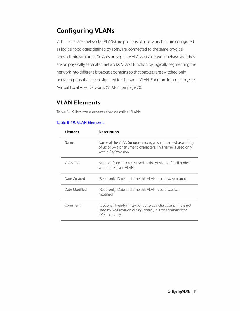
Configuring VLANs | 141
Configuring VLANsVirtual local area networks (VLANs) are portions of a network that are configured
as logical topologies defined by software, connected to the same physical
network infrastructure. Devices on separate VLANs of a network behave as if they
are on physically separated networks. VLANs function by logically segmenting the
network into different broadcast domains so that packets are switched only
between ports that are designated for the same VLAN. For more information, see
“Virtual Local Area Networks (VLANs)” on page 20.
VLAN Elements
Table B-19 lists the elements that describe VLANs.
Table B-19. VLAN Elements
Element Description
Name Name of the VLAN (unique among all such names), as a string of up to 64 alphanumeric characters. This name is used only within SkyProvision.
VLAN Tag Number from 1 to 4096 used as the VLAN tag for all nodes within the given VLAN.
Date Created (Read-only) Date and time this VLAN record was created.
Date Modified (Read-only) Date and time this VLAN record was last modified.
Comment (Optional) Free-form text of up to 255 characters. This is not used by SkyProvision or SkyControl; it is for administrator reference only.

142 | Appendix B SkyProvision Reference
VLAN Operations
Table B-20 lists the operations you can perform to configure VLANs.
Configuring Proxy Proxy ARPProxy Proxy ARP is a routing technique that uses the ARP protocol as an ad hoc
mechanism. A multi-port networking device (for example, a router) implementing
this protocol can respond to ARP requests on an interface, allowing the device to
receive and forward packets addressed to the other devices. On a SkyPilot
network, a Proxy Proxy ARP works with a VLAN to
Proxy Proxy ARP Elements
Table B-19 lists the elements that describe Proxy Proxy ARP Settings.
Table B-20. VLAN Operations
Operation From Actions
1 View Navigation pane SkyProvision ‰ VLAN (double-click)
2 Add Menu bar VLAN ‰ Add
Modify Display pane VLAN name (right-click) ‰ Modify
Delete Display pane VLAN name (right-click) ‰ Delete
Table B-21. Proxy Proxy ARP Elements (Page 1 of 2)
Element Description
Name Name of the Proxy Proxy ARP (unique among all such names), as a string of up to 64 alphanumeric characters. This name is used only within SkyProvision.
VLAN Name Name of the VLAN (unique among all such names), as a string of up to 64 alphanumeric characters. This name is used only within SkyProvision.
Router IP Address
IP address of the router that will forward addresses.

Configuring Proxy Proxy ARP | 143
Proxy Proxy ARP Operations
Table B-22 lists the operations you can perform to configure Proxy Proxy ARP.
Proxy Proxy ARP Exclusion Elements
Table B-23 lists the elements that describe Proxy Proxy ARP Exclusion settings.
Subnet Mask Used in conjunction with the network address to determine which part of the address is the network address and which part is the host address.
Comment (Optional) Free-form text of up to 255 characters. This is not used by SkyProvision or SkyControl; it is for administrator reference only.
Table B-22. Proxy Proxy ARP Setting Operations
Operation From Actions
1 View Navigation pane SkyProvision ‰ Proxy Proxy ARP Setting (double-click)
2 Add Menu bar Proxy Proxy ARP Setting ‰ New
Edit Display pane Proxy Proxy ARP name (right-click) ‰ Modify
Delete Display pane Proxy Proxy ARP name (right-click) ‰ Delete
Table B-23. Proxy Proxy ARP Exclusion Elements (Page 1 of 2)
Element Description
Proxy Proxy ARP ID
A unique ID number assigned to the Proxy Proxy ARP.
Name Name of the Proxy Proxy ARP Exclusion (unique among all such names), as a string of up to 64 alphanumeric characters. This name is used only within SkyProvision.
Table B-21. Proxy Proxy ARP Elements (Page 2 of 2)
Element Description

144 | Appendix B SkyProvision Reference
Proxy Proxy ARP Exclusion Operations
Table B-20 lists the operations you can perform to configure Proxy Proxy ARP.
Proxy Proxy ARP Setting
Name of the Proxy Proxy ARP (unique among all such names), as a string of up to 64 alphanumeric characters. This name is used only within SkyProvision.
IP Address IP address of the router that will forward addresses.
Subnet Mask Used in conjunction with the network address to determine which part of the address is the network address and which part is the host address.
Date Created (Read-only) Date and time this Proxy Proxy ARP Exclusion record was created.
Date Modified (Read-only) Date and time this Proxy Proxy ARP Exclusion record was last modified.
Comment (Optional) Free-form text of up to 255 characters. This is not used by SkyProvision or SkyControl; it is for administrator reference only.
Table B-24. Proxy Proxy ARP Exclusion Operations
Operation From Actions
1 View Navigation pane SkyProvision ‰ Proxy Proxy ARP Exclusion (double-click)
2 Add Menu bar Proxy Proxy ARP Exclusion ‰ New
Edit Display pane Proxy Proxy ARP Exclusion name (right-click) ‰ Modify
Delete Display pane Proxy Proxy ARP Exclusion name (right-click) ‰ Delete
Table B-23. Proxy Proxy ARP Exclusion Elements (Page 2 of 2)
Element Description

Configuring Customers | 145
Configuring CustomersSkyProvision allows you to manage customer records in your SkyPilot network
database. (For information about customers, see “Managing Customers” on
page 67.)
Customer Profile Elements
Table B-25 lists the elements that describe customer profiles.
Table B-25. Customer Profile Elements (Page 1 of 2)
Element Description
First Name Free-form text of up to 64 alphanumeric characters.
Last Name Free-form text of up to 64 alphanumeric characters.
Address 1 Free-form text of up to 255 alphanumeric characters.
Address 2 (Optional) Free-form text of up to 255 alphanumeric characters.
City Free-form text of up to 255 alphanumeric characters.
State/Province Free-form text of up to 255 alphanumeric characters.
Postal Code Free-form text of up to 255 alphanumeric characters.
Country Selected from a provided list.
Day Phone (Optional) Free-form text of up to 255 alphanumeric characters.
Evening Phone (Optional) Free-form text of up to 255 alphanumeric characters.
Email (Optional) Free-form text of up to 255 alphanumeric characters.

146 | Appendix B SkyProvision Reference
Customer Profile Operations
Table B-3 lists the operations you can perform to configure customer profiles.
Configuring SNMP ParametersTo enable SNMP trap alarms and SkyControl monitoring of devices, you must first
configure corresponding SNMP parameters—SNMP community strings and
SNMP trap receivers.
Related topics include:
For general information about SNMP, “SNMP” on page 25
For general information about SkyControl, “Monitoring a Network’s Topology
with SkyControl” on page 74
Date Created (Read-only) Date and time this customer profile record was created.
Date Modified (Read-only) Date and time this customer profile record was last modified.
Comment (Optional) Free-form text of up to 255 characters. This is not used by SkyProvision or SkyControl; it is for administrator reference only.
Table B-26. Customer Profile Operations
Operation From Actions
1 View Navigation pane SkyProvision ‰ Customer Maintenance (double-click)
2 Add Menu bar Customer Maintenance ‰ Add
Modify Display pane Profile name (right-click) ‰ Modify
Delete Display pane Profile name (right-click) ‰ Delete
Table B-25. Customer Profile Elements (Page 2 of 2)
Element Description

Configuring SNMP Parameters | 147
For information about customizing SNMP trap descriptions, messages, and
associated alarm severity, “Configuring Traps” on page 109
For information about customizing SkyControl SNMP queries, “Configuring
SkyControl’s SNMP Queries” on page 185
SNMP Community String Elements
Table B-27 lists the elements that describe SNMP community strings.
Table B-27. SNMP Community String Elements
Element Description
Name Name of the SNMP community string (unique among all such names), as a string of up to 64 alphanumeric characters. This name is used only within SkyProvision.
Community String
Identifier that allows access through an SNMP agent to a device’s MIB objects. Free-form text of up to 128 alphanumeric characters.
Type (Default = Read-Only) Specifies type of access allowed by this community string:
Read-Only—MIB object can be read but not modified.
Read-Write—MIB object can be read and modified.
Date Created (Read-only) Date and time this community string record was created.
Date Modified (Read-only) Date and time this community string record was last modified.
Comment (Optional) Free-form text of up to 255 characters. This is not used by SkyProvision or SkyControl; it is for administrator reference only.

148
SNMP Trap Receiver Elements
Table B-28 lists the elements that describe SNMP trap receivers.
Table B-28. SNMP Trap Receiver Elements
Element Description
Name Name of the SNMP trap receiver (unique among all such names), as a string of up to 64 alphanumeric characters. This name is used only within SkyProvision.
IP Address IP address to which any node using this trap receiver will send SNMP traps; up to 12 digits in dotted notation. The combination of IP address and port (below) must be unique (to SNMP trap receivers).
Port (Default = 162) Port to which any node using this trap receiver will send SNMP traps; number from 1 to 65535. The combination of IP address and port must be unique (to SNMP trap receivers).
Date Created (Read-only) Date and time this trap receiver record was created.
Date Modified (Read-only) Date and time this trap receiver record was last modified.
Comment (Optional) Free-form text of up to 255 characters. This is not used by SkyProvision or SkyControl; it is for administrator reference only.

Configuring Access Control Lists | 149
SNMP Operations
Table B-29 lists the operations you can perform to configure SNMP parameters.
Configuring Access Control ListsSkyProvision allows you to manage ACL records in your SkyPilot network database.
(For information about ACLs, see “Managing Access Control Lists” on page 68.)
ACL Operations
Table B-30 lists the operations you can perform to configure ACLs.
Table B-29. SNMP Operations
Operation From Actions
1 View Navigation pane SkyProvision ‰ SNMP ‰ SNMP Community String (double-click) or SkyProvision ‰ SNMP ‰ SNMP Trap Receiver (double-click)
2 Add Menu bar SNMP Community String ‰ Add or SNMP Trap Receiver ‰ Add
Modify Display pane Parameter name (right-click) ‰ Modify
Delete Display pane Parameter name (right-click) ‰ Delete
Table B-30. ACL Operations
Operation From Actions
1 View Navigation pane SkyProvision ‰ Access Control List (double-click)
2 Add Menu bar Access Control List ‰ Add
Modify Display pane ACL name (right-click) ‰ Modify
Delete Display pane ACL name (right-click) ‰ Delete

150 | Appendix B SkyProvision Reference
Configuring QoSQoS classifiers (which classify traffic according to the types of packets that will be
directed to a subscriber’s high-priority queue) and traffic filters (which control user
data packet transfer through a SkyPilot network) contribute to maintaining high
QoS. (For more information, see “Quality of Service (QoS)” on page 27.)
QoS Classifier Operations
Table B-31 lists the operations you can perform to configure QoS classifiers.
Traffic Filter Operations
Table B-32 lists the operations you can perform to configure traffic filters.
Table B-31. QoS Classifier Operations
Operation From Actions
1 View Navigation pane SkyProvision ‰ QOS ‰ Classifier (double-click)
2 Add Menu bar Classifier ‰ Add
Modify Display pane Classifier name (right-click) ‰ Modify
Delete Display pane Classifier name (right-click) ‰ Delete
Table B-32. Traffic Filter Operations
Operation From Actions
1 View Navigation pane SkyProvision ‰ Filter, then double-click desired filter type (EtherType Filter, IP Protocol Filter, IP Address Filter, or Port Filter)
2 Add Menu bar From menu corresponding to desired filter type, choose Add.
Modify Display pane Filter name (right-click) ‰ Modify
Delete Display pane Filter name (right-click) ‰ Delete

Configuring Web Servers | 151
Configuring Web ServersSkyProvision allows you to configure the Web server settings on your SkyPilot
devices.
Web Server Elements
Table B-33 lists the elements that describe Web servers.
Table B-33. Web Server Elements
Element Description
Name Name of the Web server (unique among all such names), as a string of up to 64 alphanumeric characters. This name is used only within SkyProvision.
Status Enables or disables access to the Web server on the SkyPilot device.
Customer Access Enables or disables view-only (non-administrator) access to the device’s Web interface.
Administrator Password
Password for logging in to the Web server.
Date Created (Read-only) Date and time this Web server record was created.
Date Modified (Read-only) Date and time this Web server record was last modified.
Comment (Optional) Free-form text of up to 255 characters. This is not used by SkyProvision or SkyControl; it is for administrator reference only.

152 | Appendix B SkyProvision Reference
Web Server Operations
Table B-34 lists the operations you can perform to configure Web servers.
Table B-34. Web Server Operations
Operation From Actions
1 View Navigation pane SkyProvision ‰ Web Server (double-click)
2 Add Menu bar Add
Modify Display pane Web server name (right-click) ‰ Modify
Delete Display pane Web server name (right-click) ‰ Delete
SkyPilot Network Administration | 153
Google Earth EMS Reference
SkyPilot EMS now supports views of your SkyPilot Network in Google Earth through Google Earth EMS.
With Google Earth, you can visualize that physical layout of your networks and
plan future expansion on the basis of real-world representations.
This appendix provides instructions for using Google Earth EMS to define network
profiles for viewing in Google Earth.
Appendix HighlightsStarting Google Earth EMS
Downloading icons
Changing views and creating profiles
Submitting profiles to Google Earth
Starting Google Earth EMSThe Google Earth component is automatically included as part of your SkyPilot
EMS server software installation.
To start Google Earth EMS:
1 Open a Web browser and enter the URL for the SkyPilot EMS server login page: the server’s IP address or host name, preceded by http:// (for example, http://192.168.1.228).
The Web client displays a login screen.
C

154 | Appendix C Google Earth EMS Reference
Figure C-1. EMS Web client login screen
2 Enter the user name and password. Both the default user name and the default password are admin.
3 Click Sign in.
The Web client displays its Welcome screen.
On the left, you’ll see a navigation pane displaying a hierarchical menu tree for
navigating two EMS applications, SkyProvision and Google Earth
4 Click Google Earth to display the GEMS Launchpad.
5 Click GEMS Launchpad to display the Google Earth EMS: Element View.
Your starting point for Google Earth EMS, the Element view is where you
specify how nodes and node information will be displayed in Google Earth.

Downloading icons | 155
Figure C-2. Google Earth EMS: Element View
Navigating the Google Earth EMS page
The Google Earth EMS page provides a command banner where you can build a
profile from two views (Element view and Topology view), perform a quick launch,
and download icons for network nodes displayed in Google Earth.
Downloading iconsSkyPilot provides GEMS custom node icons for use with Google Earth EMS. If you
want to use the icons tor represent network nodes, you must download the icons.
To download the Google Earth EMS icons:
1 Click Download Icons in the banner menu.
The Web client displays a login screen.

156 | Appendix C Google Earth EMS Reference
If the icons are not currently installed on your computer, SkyPIlot EMS will display a
reminder in the message area of the Google Earth EMS asking you to install the
icon package.
If you are using a Windows computer as the EMS client, you will download an
installer the walks you through the installation process.
If the SkyPilot EMS client is running on a computer OS other than Windows, click
Non-Windows to download an package of icons with a Readme file containing
instructions for installing the icons on your computer.
Installing Google Earth EMS icons on a Windows-based client
To install the icon package:
1 Click Microsoft Windows in the Operating System column.
A prompt appears, providing options for downloading the installer,
gems_icons.exe.
2 Choose a destination and click Save.
3 Run gems_icons.exe.
The Installer starts and asks you to selected the components to install.
4 Check SkyPilot EMS 1.5 Google Earth Icons and click Install.
The installer copies the SkyPilot icons to the a location where they will be
available to Google Earth.
5 Click Close.
Creating and viewing network profiles
You view SkyPilot networks in Google Earth by defining a profile and opening it in Google Earth as a “place: that you can browse and save for latter viewing.
When you submit a profile to Google Earth, EMS creates a KML file that Google
Earth uses to map network node information to the physical world.

Creating and viewing network profiles | 157
Google Earth adds the network profile to your Temporary Places folder as the
subfolder with the same name as the profile.
When you click the entry, Google Earth “flies” to the physical location of the
network and zooms in to a view showing the nodes you specified in the profile.
Note Newly submitted profiles appear as items in the Temporary Places folder. If you do not move these items to the My Places folder to save them, they will not be retained when you quit Google Earth.
Create a profile in Element view
Element view prepares a Google Earth view of your network based on the various
elements of the network, including type of node, node state, link state, device
frequency, and number of hops.
Click Element View on the command banner to open the Element View page and
start creating a new profile for viewing in Google Earth.
Figure C-3. Profile Settings Element View page
158 | Appendix C Google Earth EMS Reference
Use the provided fields and checkboxes to specify element view options and
provide a profile name.
Icon view.
Use the Icon radio buttons to specify the type of icons that will appear in Google
Earth.
Click Show Node Type to display the network in Google Earth with node type
icons. Click Show Hop Count to display the network in Google Earth with hop
count icons.
Color
Use these radio buttons to specify the use of color in identifying different
elements in Google Earth.
Domain
Click checkboxes that correspond to the domain(s) you want Google Earth to
display. The domains listed correspond to the domains currently active in the
SkyPilot network.
Click Check/Uncheck all to select all or none of the listed domains for viewing.
Click Group by Domain to group nodes according to the domain in which they
reside.
Frequency (MHz)
Click checkboxes that correspond to the frequencies of the devices you want to
view in Google Earth. The frequencies assigned to the checkboxes correspond to
frequences currently used in the SkyPilot network.
Click Include All to select all or none of the listed frequencies for viewing. Click
Group by Frequency to group nodes by the frequency they use for network
communications.
Hops
Click checkboxes that correspond to the number of “hops” you want to view in
Google Earth.

Creating and viewing network profiles | 159
Click Include All to select all or none of the listed hops for viewing. Click Group
by Hop to group nodes by the number of hops they are from the network
gateway.
Node type
Click checkboxes that correspond to the type of SkyPilot nodes you want to view
in Google Earth--SkyGateway, SkyExtender DualBand, SkyExtender TriBand, and
SkyExtender Outdoor.
Click Include All to select all or none of the listed node types for viewing. Click
Group by Node type to group nodes by the node type.
Node state
Cick the checkboxes that correspond to the current state of SkyPilot nodes--active
or inactive--you want to view in Google Earth.
Click Group by Node State to group nodes by their current state.
Link state
Cick the checkboxes that correspond to the link state of SkyPilot nodes you want
to view in Google Earth--Active, Standby, Transition, or Failed.
Click Group by Link State to group nodes by their current link state.
Auto Refresh
Cick the Auto Refresh checkbox to specify auto refresh of the SkyPilot network
information displayed in Google Earth--Active, Standby, Transition, or Failed.
Refresh Rate
Use the Refresh Rate field to enter frequency of refresh (in seconds).
Wi-Fi Radius
For SkyExtender DualBand and SkyExtender TriBand nodes, you can represent the
radius of Wi-Fi coverage in Google Earth.

160 | Appendix C Google Earth EMS Reference
Select Feet or Meters from the Wi-Fi Radius pull down and enter a radius value in
the field.
Element View in Google Earth
After setting your parameters for an Element profile, click Submit to open the
profile in Google Earth.
Isolate the view of your network place by clicking the GEMS Network folder. Filter
elements and nodes by clicking items in the subfolders.
Figure C-4. Sample SkyPilot network Place (Element view)
Creating a profile in Topology view
Use the Topology view to prepare a Google Earth view of your network that
groups devices on the basis of their active link topology. A topology view helps
you understand the relationships between the devices and is useful for viewing
the network hierarchy.
Click Topology View on the command banner to open the Topology View page
and start creating a new profile for viewing in Google Earth.

Creating and viewing network profiles | 161
Figure C-5. Profile Settings Topology View page
Use the provided fields and checkboxes to specify element view options and provide a profile name.
Icon view.
Use the Icon radio buttons to specify the type of icons that will appear in Google
Earth.
Click Show Node Type to display the network in Google Earth with node type
icons. Click Show Hop Count to display the network in Google Earth with hop
count icons.
Color
Use these radio buttons to specify the use of color in identifying different
elements in Google Earth.

162 | Appendix C Google Earth EMS Reference
Domain
Click checkboxes that correspond to the domain(s) you want Google Earth to
display. The domains listed correspond to the domains currently active in the
SkyPilot network.
Click Include All to select all or none of the listed domains for viewing. Click
Group by Domain to group nodes according to the domain in which they reside.
Gateway
Click checkboxes that correspond to the SkyPilot SkyGateways currently available
for viewing in Google Earth.
Click Include All to select all or none of the listed SkyGateways for viewing.
Node Type
Click checkboxes that correspond to the type of SkyPilot nodes you want to view
in Google Earth--SkyGateway, SkyExtender, SkyExtender DualBand, SkyExtender
TriBand, SkyConnector Indoor, SkyExtender Outdoor, and SkyAccess DualBand.
Click Include All to select all or none of the listed node types for viewing. Click
Group by Node Type to group nodes by the type of device
Node State
Cick these checkboxes to set up view of the network based on the current state of
SkyPilot nodes--Up, Down, SNMP Unreachable, Polling Disabled, and Discovered.
Click Group by Node State to group nodes by their current state.
Auto Refresh
Cick the Auto Refresh checkbox that specify auto refresh of the SkyPilot network
information displayed in Google Earth--Active, Standby, Transition, or Failed.
Refresh Rate
Use the Refresh Rate field to enter the refresh frequency (in seconds).

Creating and viewing network profiles | 163
Wi-Fi Radius
For SkyExtender DualBand, SkyExtender TriBand, and SkyAccess DualBand nodes,
you can represent the radius of Wi-Fi coverage in Google Earth.
Select Feet or Meters from the Wi-Fi Radius pull down and enter a radius value in
the field.
Topology view in Google Earth
After setting the parameters for a topology view, click Submit to send the profile
to Google Earth.
Isolate the view of your network place by clicking the GEMS Network folder. Filter
elements and nodes by selecting and de-selecting items in the GEMS Network
subfolders.
Figure C-6. Sample SkyPilot network place (topology view)
Performing a quick launch
Use the Quick Launch view to quickly prepare and submit a Google Earth view of
your network based on specific network elements such as the domain or
SkyGateway the serves as the network hub.

164 | Appendix C Google Earth EMS Reference
Click Quick Launch on the command banner to open the Quick Launch page and
start creating a new profile for viewing in Google Earth.
Figure C-7. Profile Settings Quick Launch page
Links at the top of the page instantly launch a Google Earth view of the SkyPilot
network based on the selected domain or SkyGateway with default parameters.
Use the provided check boxes and fields to select viewing options and provide a
profile name.
Icon
Use the Icon radio buttons to specify the type of icons that will appear in Google
Earth.
Click Show Node Type to display the network in Google Earth with node type
icons. Click Show Hop Count to display the network in Google Earth with hop
count icons.

Creating and viewing network profiles | 165
Color
Use these radio buttons to specify the use of color in identifying different
elements in Google Earth.
Domain
Click checkboxes that correspond to the domain(s) you want Google Earth to
display. The domains listed correspond to the domains currently active in the
SkyPilot network.
Click Include All to select all or none of the listed domains for viewing. Click
Group by Domain to group nodes according to the domain in which they reside.
Frequency (MHz)
Click checkboxes that correspond to the frequencies of the devices you want to
view in Google Earth. The frequencies assigned to the checkboxes correspond to
frequences currently used in the SkyPilot network.
Click Include All to select all or none of the listed frequencies for viewing. Click
Group by Frequency to group nodes by the frequency they use for network
communications.
Hops
Click checkboxes that correspond to the number of “hops” you want to view in
Google Earth.
Click Include All to select all or none of the listed hops for viewing. Click Group
by Hop to group nodes by the number of hops they are from the network
gateway.
Node Type
Click checkboxes that correspond to the type of SkyPilot nodes you want to view
in Google Earth--SkyGateway, SkyExtender, SkyExtender DualBand, SkyExtender
TriBand, SkyConnector Indoor, SkyExtender Outdoor, and SkyAccess DualBand.
Click Include All to select all or none of the listed node types for viewing. Click
Group by Node Type to group nodes by the type of device

166 | Appendix C Google Earth EMS Reference
Node State
Cick these checkboxes to set up view of the network based on the current state of
SkyPilot nodes--Up, Down, SNMP Unreachable, Polling Disabled, and Discovered.
Click Group by Node State to group nodes by their current state.
Auto Refresh
Cick the Auto Refresh checkbox that specify auto refresh of the SkyPilot network
information displayed in Google Earth--Active, Standby, Transition, or Failed.
Refresh Rate
Use the Refresh Rate field to enter the refresh frequency (in seconds).
Wi-Fi Radius
For SkyExtender DualBand, SkyExtender TriBand, and SkyAccess DualBand nodes,
you can represent the radius of Wi-Fi coverage in Google Earth.
Select Feet or Meters from the Wi-Fi Radius pull down and enter a radius value in
the field.
Quick launch view in Google Earth
After setting the parameters for a quick launch view, click Submit to send the
profile to Google Earth.
Isolate the view of your network place by clicking the GEMS Network folder. Filter
elements and nodes by clicking items in the folder.

Creating and viewing network profiles | 167
Figure C-8. Sample SkyPilot network place (Quick Launch view)

168 | Appendix C Google Earth EMS Reference

SkyPilot Network Administration | 169
SkyControl Reference
SkyControl enables you to perform administrative and maintenance functions for your SkyPilot network. This appendix provides detailed instructions for using those functions through the SkyPilot EMS Java client.
Appendix HighlightsUsing SkyControl
Viewing your SkyPilot network
Configuring SkyControl’s SNMP queries
Configuring data collection tasks
Configuring threshold alarms
Using reports
Viewing statistics
D

170 | Appendix D SkyControl Reference
Using SkyControlSkyControl is an SNMP management system for real-time device monitoring and
management. It provides a graphical view of your network topology with at-a-
glance updates on topology, routing, and performance.
Starting SkyControl
You access SkyControl from the SkyPilot EMS Java client. If SkyProvision is already
active, you don’t need to start another SkyPilot EMS Java client session; both
SkyProvision and SkyControl can be run within a single SkyPilot EMS Java client
session.
NOTE In addition to the following procedure, you may be able to start the EMS Java client by using the Start menu or desktop shortcuts that may have been set up during installation.
To access SkyControl:
1 Execute the SkyPilot EMS Java client startup script, SkyPilot\EMS\bin\startemsclient.bat (for Windows systems) or /usr/local/skypilot/EMS/bin/startsemsclient.sh (for Linux systems).
The Login window is displayed (Figure D-1).

Using SkyControl | 171
Figure D-1. SkyPilot EMS Login window
2 Enter your user name and password.The default user name is admin, and the default password is also admin.
3 Click Login.
The SkyPilot EMS Java client interface is displayed.
Figure D-2. SkyPilot EMS Java client interface

172 | Appendix D SkyControl Reference
For information about the SkyPilot EMS Java client interface elements, see
“The SkyPilot EMS Java Client Interface” on page 104.
4 Click SkyControl in the navigation pane.
The SkyControl item in the navigation pane expands to show the entire list of
configured domains. The Tools menu changes to list SkyControl tools, and the
display pane changes to a blank display (which will be filled once you select
domains to monitor).
SkyControl Interface
Figure D-3 illustrates the various parts of the SkyControl interface, including
elements in its display pane.
Figure D-3. SkyControl interface
The various parts of the interface are as follows:
Map toolbar—Toolbar that’s active when a monitored domain map is shown
in the display pane.
Use the arrow button to lock and unlock a node’s position in the map display. When a node is unlocked, you can drag it to any position in the map.
Use the zoom level buttons to zoom in and out of the map display to any level. Use the leftmost button for maximum zoom out, the rightmost button for maximum zoom in, and the buttons in between for intermediate zoom levels. The highlighted button indicates the current zoom level.
Use the magnifying glass to zoom in and out of the map display by a single level.
Map toolbar
Display pane, Display background
Link line
Node icons
Device menu access

Using SkyControl | 173
Link lines—Representations of links between nodes. Link lines are added as
nodes form links with each other, which begins for each node when the node’s
polling starts (when the node is added if an IP address is specified, or via the
device’s Poll Now function or the device domain’s Start Polling All Devices
function, as described in Table D-2).
Node icons—Representations of SkyPilot nodes. The icon’s background color
represents the current state of the node: gray indicates that there is no polling
for the node; red indicates that the node is not responding and therefore is not
currently an active part of the network; and green means the node is active.
Table D-1 shows the icon for each type of node.
Device menu access—Right-clickable device name, which is used to access
the SkyControl device menu (Figure D-4). Table D-2 provides descriptions or
references to the applicable documentation section for each menu option.
Table D-1. Node Icons
SkyGateway
SkyExtender
SkyExtender DualBand
SkyExtender TriBand
SkyConnector Outdoor
SkyConnector Indoor

174 | Appendix D SkyControl Reference
Figure D-4. SkyControl device menu
Table D-2. Device Menu Options (Page 1 of 3)
Option Description/Reference
Device Details Displays the device’s configuration settings, polling details, Ethernet statistics, and link information. See “Viewing Detail Data” on page 183.
Poll Now Enables an immediate single SkyControl poll of the device to update the default task statistics.
Configure Task Displays a window in which you can add, modify, start, and stop data collection tasks. See “Configuring Data Collection Tasks” on page 187.
Configure Report Displays a window in which you can add, modify, and delete report configurations (included objects, frequency of data collection, and report format). See “Configuring Reports” on page 190.
View Report Displays a window in which you can select a report to view or to chart. See “Viewing Detail Data” on page 183.
View Current Statistics
Displays a window in which you can select devices, data collection tasks, objects, instances, and plotting options to create a dynamically updated graphical view of device statistics. See “Viewing Current Statistics” on page 192.

Using SkyControl | 175
View Collected Statistics
Displays a window in which you can select devices, data collection tasks, objects, instances, time period, and plotting options to create a static graphical view of device statistics. See “Viewing Collected Statistics” on page 193.
Change Community
Displays a window in which you can configure the SNMP community string that SkyControl uses to poll the device. See “Configuring SkyControl’s SNMP Queries” on page 185.
Set Resource Parameters
Displays a window in which you can configure the SNMP polling timeout and retries that SkyControl uses to monitor the device. See “Configuring SkyControl’s SNMP Queries” on page 185.
Delete Deletes the selected node. (This is a shortcut for the Node Maintenance delete function.)
Node Displays the node’s provisioning parameters. (This is a shortcut for the Node Maintenance view function.)
Node Profile Displays the node’s associated node profile settings. (This is a shortcut for the Node Profile view function, except that you can’t modify the node profile.)
Customer Profile Displays the node’s associated customer profile, if any. (This is a shortcut for the Customer Profile view function, except that you can’t modify the customer profile.)
MIB Browser Opens the MIB browser, which you can use to view the SkyPilot MIB objects associated with the current node.
MIB Browser AP (DualBand/TriBand only; access point polling not currently implemented)
Alarm Displays the Related Alarms window showing all current alarms for the device.
Telnet Opens a Telnet session to the device’s command-line interface; helpful for debugging.
Table D-2. Device Menu Options (Page 2 of 3)
Option Description/Reference

176 | Appendix D SkyControl Reference
Display background—Background image on which the nodes and links are
shown. You can customize the background and then position the network’s
node icons in the correct location so that the display of the network topology
accurately represents real life. For example, if you use a street map as the
background and an end user’s location is at the corner of Pine and Main
streets, you can drag the associated SkyConnector icon directly onto the map
at that corner. (For directions on customizing the display background, see
“Customizing the SkyControl Display Pane” on page 179.)
Typical Configuration Operations
There is a pattern to the way configuration operations are performed in
SkyControl and how they’re described in the rest of this appendix. This section
explains the pattern; subsequent sections discuss the various configuration
operations in a concise way that provides any extra information you’ll need to
know once you’ve become familiar with the pattern.
Configuring Section
Each main topic begins with a Configuring section that introduces what you’ll
learn to configure—for example, “Configuring Data Collection Tasks” and
“Configuring Threshold Alarms.”
Telnet AP (DualBand/TriBand only; port forwarding to access point’s Linux command shell not currently implemented)
Discovery Configuration
Displays the Discover Configuration window where you enable or disable whether SkyControl displays nodes connected to the selected device that the device sees in its link state table, regardless of whether the connected devices are in the selected device’s provisioning records.
Node’s Path Historical Polling
(Non-SkyGateways only) Starts, stops, or displays the RSSI, modulation, and/or throughput data for the device’s path that was active at a specified time. See “Viewing Detail Data” on page 183.
Table D-2. Device Menu Options (Page 3 of 3)
Option Description/Reference

Using SkyControl | 177
Elements Section
The first subsection within a Configuring section is typically an Elements section
that presents a table listing the elements related to the applicable configuration—
for example, “Data Collection Task Elements” presenting a table that lists elements
such as Name for the data collection task name, Frequency for the polling
frequency, and so on. There may be multiple Elements sections for closely related
items. Alternatively, you may be directed to an Elements section located
elsewhere in this document.
Operations Section
Next, the Operations section uses a concise tabular presentation to show the
configuration operations and how to perform them, similar to Table D-3 for (a
subset of ) data collection tasks.
To use one of these tables, first look in the Operation column to find the
operation you want to perform. If there are any lower-numbered steps, perform
their actions first, and then perform the desired operation’s actions. For example, if
you wanted to modify a data collection task, you’d perform the action for step 1 in
Table D-3 and then the action for the Modify operation in step 2. Spelled out in
full, the procedure to modify a data collection task would be as follows:
1 If the list of devices in the desired domain is not already showing in the navigation pane, expand the SkyControl tree in the navigation pane, expand
Table D-3. SkyControl Configuration Operations Example Table
Operation From Actions
1 View Navigation pane SkyControl ‰ Domain ‰ Device name (right-click); choose Configure Task
2 Add Display pane New
Modify Display pane Task name (click) ‰ Edit
Delete Display pane Task name (click) ‰ Delete

178 | Appendix D SkyControl Reference
the desired domain tree, right-click the desired device’s name, and choose Configure Task.
SkyControl displays the Configure Task screen.
Figure D-5. Configure Task screen
2 Click the name of the task whose settings you want to modify, and then click Edit.
SkyControl displays the same screen as when you add a new task.
Figure D-6. Adding or modifying a data collection task
Using SkyControl | 179
3 Edit the task elements and click OK.
Focus returns to the earlier Configure Task screen (Figure D-5).
4 Click Close.
You can see from Table D-3 that the actions you’d take to delete a data collection
task would be very similar to those in the procedure just described, as would the
actions for adding a data collection task.
Note that where a configuration procedure includes choosing a command from a
navigation pane right-click menu, you may be able to do so not only with the
mouse but also with a keyboard shortcut, from the display area of the display pane
by right-clicking the desired item, or from the navigation pane by double-clicking
the desired item in the expanded SkyControl tree and selecting an item from the
resulting menu bar.
Regardless of what you’re configuring, the operations will follow a similar pattern
to what’s shown in Table D-3, and where there are variations the table will use the
same notational conventions as in Table D-3.
Customizing the SkyControl Display Pane
For each EMS Java client session (that is, each separate SkyControl instance), you
can customize the display pane, including the display background, on a per-
domain basis. So, for example, you could show all the links for one domain but
only active links for another domain.
TIP It’s important to remember which display settings you’ve configured; otherwise, you might spend time troubleshooting a device because it isn’t appearing in a nonoperating domain’s SkyControl display, only to discover that you’ve configured the display to show only provisioned nodes.
To customize a domain’s display pane:
1 In the navigation pane of SkyPilot EMS Java client, expand the SkyControl tree (if it’s not already expanded).
The SkyControl tree expands to show the complete list of configured
domains.

180 | Appendix D SkyControl Reference
2 If you don’t want to change the display background, skip to step 4.
To change the background, right-click the name of the domain whose
background you want to customize, and choose Change Background.
SkyControl displays the Open screen.
Figure D-7. Open screen
3 Browse to the desired file, select it, and click Open.
SkyControl replaces the previous background with the image in the file you’ve
opened. (If the domain isn’t currently displayed, you’ll see the new
background the next time you view the domain.)
NOTE You must separately add the image to every PC on which you run the EMS Java client.
If you don’t want to change which nodes and links are shown (including
whether their accompanying labels are shown), you’re done with this
procedure. Otherwise continue with the next step.
4 To configure other display settings, right-click the name of the domain whose display you want to customize, and choose Display Configuration.
SkyControl displays the Display Configuration screen.

Using SkyControl | 181
Figure D-8. Display Configuration screen
5 Select the desired options and click OK.
Searching for Configured Devices
You can search for any network configured device, which can be helpful if you
have many devices shown in the SkyControl display. For example, your network
may have hundreds of nodes, and finding the one you want examine may be
difficult. But if you know the node’s name, MAC address, or IP address, you can use
the search function to find just those nodes that match your search criteria.
To search for configured devices:
1 Expand the SkyControl tree, right-click the domain containing the desired device, and choose Search.
2 Select how you want to search—Name, MAC Address, or IP Address—and enter your search criteria.
3 Click Search.
The domain is displayed with the desired device highlighted.

182 | Appendix D SkyControl Reference
Viewing Your SkyPilot NetworkSkyControl provides a graphical view of your network topology (including all
network nodes and links) with at-a-glance updates on topology, routing, and
performance. In addition, tabular statistics details are available for devices, links,
and node path history.
Viewing Domains
You can view graphical representations of either a single domain or multiple
domains at a time (one domain per window). As described in the preceding
section, you can change the display configuration on a per-domain basis.
SkyControl directly polls all SkyPilot devices that are provisioned with a static IP
address. In addition, it polls each SkyGateway to retrieve the list of devices
connected to the SkyGateway, including their IP addresses; in this manner, devices
with dynamically assigned IP addresses can be monitored by SkyControl.
IMPORTANT When a device with a dynamically assigned IP address is added to the network, SkyControl cannot poll the new node until its IP address is discovered (by polling the SkyGateway). Once the IP address is discovered, you must tell SkyControl to start polling all devices (even if SkyControl is already polling all devices) or select the device and start its default task. (If a node’s IP address changes, SkyControl automatically polls the node at its new address.)
To view a domain:
1 In the navigation pane of SkyPilot EMS, expand the SkyControl tree (if it’s not already expanded).
The SkyControl tree expands to show the complete list of configured
domains.
2 In the navigation pane, double-click the domain you want to view.
SkyControl displays the domain’s primary SkyGateway in the display pane.
However, no other network nodes are shown until you instruct SkyControl to
begin polling the SkyGateway (in the next step).

Viewing Your SkyPilot Network | 183
3 In the navigation pane, right-click the name of the domain you’re viewing, and choose Start Polling All Devices.
The nodes within the domain automatically discover one another, and
SkyControl automatically adds node icons to the display, as well as link lines
once the links are formed.
NOTE By default, polling is on for all devices. However, if you don’t need to monitor the network for some time, it’s recommended that you stop the SkyControl polling in order to avoid filling the database with unneeded data.
Viewing Detail Data
You can view the following detail data for any SkyPilot device that’s being
monitored by SkyControl:
A snapshot of any SkyPilot device that’s included in the EMS default
statistics data collection task, which SkyPilot EMS automatically creates
for devices when they’re added to the network. (To view statistics from custom
data collection tasks, use the procedure described in “Viewing Current
Statistics” on page 192.)
A snapshot of any link between two network devices
Historical path information
Reports
To view detail data:
1 Display the domain to which the device belongs (see “Viewing Domains” on page 182).

184 | Appendix D SkyControl Reference
2 Follow the instructions in Table D-4 to view the available details.
Table D-4. Viewing Details
To view Do this
Device Details Right-click either the corresponding node icon or the node’s name in the navigation pane, and choose Device Details.
LInk Details Right-click the corresponding link icon in the navigation pane, and choose Link Details.
For the most accurate link, the polling intervals for the link’s connected devices should be the same.
Node Path History Right-click either the corresponding node icon or the node’s name in the navigation pane, and choose Node’s Path Historical Polling ‰ View.
To stop and start the polling that populates the node path history, right-click either the corresponding node icon or the node’s name in the navigation pane, and choose Node’s Path Historical Polling ‰ Start or Node’s Path Historical Polling ‰ Start, respectively.
If the active path changes (that is, the device reroutes and starts sending its data to a new parent), the polling logic takes that into account, always polling the correct link.
Report Right-click either the corresponding node icon or the node’s name in the navigation pane, and choose View Report; from the View Report screen, select the desired report and which MIB objects to include, and click View or Chart.
For more information, see “Using Reports” on page 190.

Configuring SkyControl’s SNMP Queries | 185
Configuring SkyControl’s SNMP QueriesWhen you configure a device, you can configure it with specific SNMP community
strings that enable SkyControl to poll the device. If no SNMP community string is
configured, SkyControl uses the default read-only community string, public.
If you change a device’s SNMP community string after the device is configured
and added to the network (by changing the applicable profile for automatically
provisioned devices, and by using the device’s Web or command-line interface for
manually provisioned devices), the node stops responding to SkyControl queries
(because SkyControl is still using the original SNMP string), and SkyControl can no
longer monitor the device. To reenable SkyControl monitoring, you must change
the community string that SkyControl uses, as described in the next procedure.
In addition to the community string itself, you can configure the following SNMP
query parameters:
Timeout—How long SkyControl waits for a response to a polling request
(SNMP query) before deciding that the device failed to respond.
Retries—Number of times after a SkyControl polling query timeout that
SkyControl repeats the polling query before deciding that the device is down.
For example, if Retries is 3, a device is determined to be down if four
consecutive SkyPilot queries time out.
You can change the SNMP query parameters as described below.
To configure SkyControl SNMP queries:
1 In the navigation pane of SkyPilot EMS, expand the SkyControl tree (if it’s not already expanded).
The SkyControl tree expands to show the complete list of configured
domains.
2 Expand the domain tree that contains the device for which you want to configure a data collection task (if it’s not already expanded).
The domain tree expands to show the complete list of devices in the domain.

186 | Appendix D SkyControl Reference
3 To change the community string SkyControl uses to poll the device, right-click the desired device name and choose Change Community.
SkyControl displays the Change Community String screen (Figure D-9).
Figure D-9. Change Community String screen
Clear the Set Default Read Community check box, select the desired
community from the drop-down list, and click OK.
4 To change the SNMP query parameters SkyControl uses to poll the device, right-click the desired device name and choose Change Resource Parameters.
SkyControl displays the Set Resource Parameters screen (Figure D-10).
Figure D-10. Set Resource Parameters screen
Modify the desired parameters and click OK.

Configuring Data Collection Tasks | 187
Configuring Data Collection TasksData collection tasks collect data from the SkyPilot MIB for a specific device, at
defined intervals, for defined periods of time. The collected information is stored
on the EMS server, in its database.
NOTE After configuring a data collection task for a device, you must explicitly start the task before any of its statistics can be viewed.
Data Collection Task Elements
Table D-5 lists the elements that describe data collection tasks. (Instead of
appearing on a single screen, these elements are shown on a progression of
screens, much like a Data Collection Task wizard.)
Table D-5. Data Collection Task Elements (Page 1 of 2)
Element Description
Data Collection Name
Name of the data collection task (unique among all such names), as a string of up to 64 alphanumeric characters. This name is used only within SkyControl.
Copy To Resource
(Read-only) Copies the task to other devices.
MIB MIB browser to which you can load a MIB and select objects to poll.
Performance Objects
Object to poll; moved from the left to right list to enable selection.
Object Identifier (Read-only) MIB object identifier selected for MIB element.
Display Name Editable text displayed for the data object in reports, events, and alarm displays.
Threshold Threshold to apply to configure this task’s object as an alarm; selected from a provided list.
Reschedule Interval
Number of time intervals between data collections. The type of time interval is selected from a provided list—for example, Minute or Hour.

188 | Appendix D SkyControl Reference
Data Collection Task Operations
Table D-6 lists the operations you can perform to configure data collection tasks.
Start Collecting Data From
Date and time to start running the data collection task; selected from the calendar.
End Collecting Data By
Date and time to stop running the data collection task; selected from the calendar.
Store Collected Data
Enables or disables storing the collected data.
Purge Data Older Than
Age of data to purge; interval is selected from a provided list.
Table D-6. Data Collection Task Operations
Operation From Actions
1 View Navigation pane a SkyControl ‰ Domain ‰ Device name (right-click)
b Choose Configure Task
2 Add Menu bar New ‰ Data Collection Task wizard
Copy Display pane Task name (click) ‰ Copy
Stop Display pane Task name (click) ‰ Stop
Modify Display pane Task name (click) ‰ Edit
Delete Display pane Task name (click) ‰ Delete
Start Display pane Task name (click) ‰ Start
Table D-5. Data Collection Task Elements (Page 2 of 2)
Element Description

Configuring Threshold Alarms | 189
Configuring Threshold AlarmsThreshold alarms are created when SkyControl interprets events according to
preconfigured and custom MIB object thresholds.
Threshold Alarm Operations
Table D-7 lists the operations you can perform to configure threshold alarms.
Table D-7. Threshold Alarm Operations
Operation From Actions
1 View Navigation pane SkyControl ‰ Domain ‰ device name (right-click); choose Configure Task ‰ task name
Typically, the task you’ll choose is status_poll—the default device polling task.
2 Add Display pane New ‰ Select the desired threshold (or None to remove the alarm trigger for an event) for the Threshold element displayed by the Data Collection Task wizard.
Modify Display pane Edit ‰ Select the desired threshold (or None to remove the alarm trigger for an event) for the Threshold element displayed by the Data Collection Task wizard.
(A task must be stopped in order to be modified.)
Delete Display pane Delete ‰ Select None for the threshold of the Threshold element displayed by the Data Collection Task wizard.
(A task must be stopped in order for an associated threshold alarm to be deleted.)
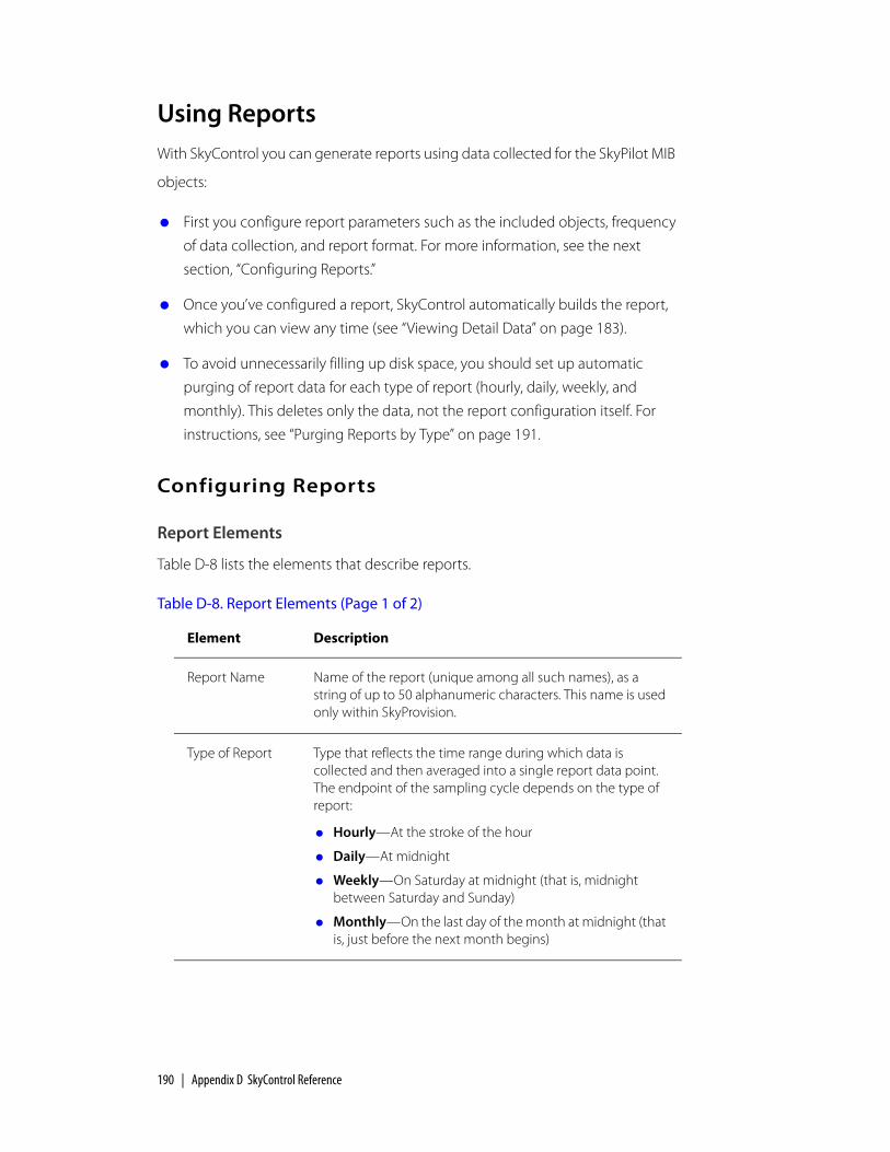
190 | Appendix D SkyControl Reference
Using ReportsWith SkyControl you can generate reports using data collected for the SkyPilot MIB
objects:
First you configure report parameters such as the included objects, frequency
of data collection, and report format. For more information, see the next
section, “Configuring Reports.”
Once you’ve configured a report, SkyControl automatically builds the report,
which you can view any time (see “Viewing Detail Data” on page 183).
To avoid unnecessarily filling up disk space, you should set up automatic
purging of report data for each type of report (hourly, daily, weekly, and
monthly). This deletes only the data, not the report configuration itself. For
instructions, see “Purging Reports by Type” on page 191.
Configuring Reports
Report Elements
Table D-8 lists the elements that describe reports.
Table D-8. Report Elements (Page 1 of 2)
Element Description
Report Name Name of the report (unique among all such names), as a string of up to 50 alphanumeric characters. This name is used only within SkyProvision.
Type of Report Type that reflects the time range during which data is collected and then averaged into a single report data point. The endpoint of the sampling cycle depends on the type of report:
Hourly—At the stroke of the hour
Daily—At midnight
Weekly—On Saturday at midnight (that is, midnight between Saturday and Sunday)
Monthly—On the last day of the month at midnight (that is, just before the next month begins)

Using Reports | 191
Report Operations
Table D-9 lists the operations you can perform to configure reports.
Purging Reports by Type
For each type of report (hourly, daily, weekly, and monthly), you can set up
automatic purging of reports of that type from your system (without deleting the
individual report configurations) to avoid unnecessarily filling up disk space. You
can specify a different purge frequency for each type of report.
To set up report purging:
1 From the SkyPilot EMS Java client menu bar, choose Performance ‰ Configure Report Data Clear Interval.
SkyPilot EMS Java client displays the screen shown in Figure D-11.
Performance Objects
MIB objects that have been configured for data collection through any of the device’s data collection tasks. (See “Data Collection Tasks” on page 71.)
Table D-9. Report Operations
Operation From Actions
1 View Navigation pane a SkyControl ‰ Domain ‰ Device name (right-click)
b Choose Configure Report
2 Add Display pane New
Modify Display pane Edit
Delete Display pane Delete
Table D-8. Report Elements (Page 2 of 2)
Element Description

192 | Appendix D SkyControl Reference
Figure D-11. Setting a report purge interval
2 Select the report type from the provided list.
3 Enter a number to specify the age (in days) of data that you want to purge, and click OK.
Viewing StatisticsThe following sections describe how to view both current and collected statistics.
For information about SkyPilot statistics, see “About Reports and Statistics” on
page 70.
Viewing Current Statistics
You can view the current statistics for any data collection task that is not running.
To view current statistics:
1 In the navigation pane of SkyPilot EMS, expand the SkyControl tree (if it is not already expanded).
The navigation pane expands to show the complete list of configured
domains.
2 Expand the domain tree (if it is not already expanded) that contains the device for which you want view current statistics.
The navigation pane expands to show the complete list of devices in the
domain.
3 Right-click the desired device name and choose View Current Statistics.
SkyControl displays the Current Statistics screen.

Viewing Statistics | 193
4 Select the devices, data collectors, MIB objects, and instances you want to view, the desired plot type (Line, Stacked Line, Bar, Stacked Bar, or Pie), enter a polling interval, and click Start.
SkyControl displays the statistics in real time, similar to the example shown in
Figure D-12.
Figure D-12. Current Statistics view
5 When you’re done viewing the statistics, click Stop and Close.
Viewing Collected Statistics
You can view collected statistics for any data collection task that is not running.
To view collected statistics:
1 In the navigation pane of SkyPilot EMS, expand the SkyControl tree (if it is not already expanded).
The navigation pane expands to show the complete list of configured
domains.

194 | Appendix D SkyControl Reference
2 Expand the domain tree (if it is not already expanded) that contains the device for which you want view a report.
The navigation pane expands to show the complete list of devices in the
domain.
3 Right-click the device name for which you want the report, and choose View Collected Statistics.
SkyControl displays the Collected Statistics screen.
Figure D-13. Collected Statistics screen
4 Select the parameters, configure the graph elements (such as the axis settings and graph type), choose the time frame, and then click one of the following:
Plot—Plots the statistics corresponding to the settings you’ve chosen
Clear—Clears the display so you can change the settings
Save—Saves the display
Print—Prints the display
5 When you’re done viewing the statistics, click Close.

SkyPilot Network Administration | 195
Configuring a Firewall for SkyPilot OperationsFor optimal SkyPilot operations, you should install your operating system without
a firewall. However, if security concerns or other issues force you to use a firewall,
you must configure the firewall to allow incoming data traffic on ports that
SkyPilot clients and devices use for server communications (see Table E-1).
NOTE Each port you open reduces the overall security provided by the firewall.
Table E-1. Ports to Open
To do this Open these ports
Allow EMS Java clients to connect to the EMS server
1098 TCP (JBoss RMI port)
1099 TCP (JBoss RMI port)
4444 TCP (JBoss RMI object port)
3306 TCP (MySQL DB port)
32007 (Notification port)
Allow EMS Web clients to connect to the EMS server
80 (HTTP server)
Allow SkyProvision to configure SkyPilot devices outside the firewall
8000 TCP (HTTP server)
20 TCP (FTP server)
21 TCP (FTP server)
67 TCP/UDP (DHCP server)
Allow SkyControl to monitor SkyPilot devices outside the firewall
161 TCP/UDP (SNMP Read)
162 UDP (SNMP Traps)
E

196

SkyPilot Network Administration | 197
Access Point Command-Line Interface
The access point command-line interface enables SkyPilot support to debug the access point configuration through the Linux command shell. This appendix provides instructions for accessing the interface.
Checking VLAN StatusBefore you can access a DualBand’s or TriBand’s access point command-line
interface, you must first check the VLAN status.
If your SkyPilot network is configured to use a management VLAN, the access
point automatically uses that VLAN for management traffic. Therefore, you’ll need
to access the access point from a PC that’s a member of that management VLAN.
Typically this means you’ll need to access the Web interface from the SkyPilot EMS
server or other management workstation across the SkyPilot mesh network. If
you’ve previously configured a management SSID as a member of the
management VLAN, you can use this SSID to connect directly to the access point.
Accessing the InterfaceYou use a Wi-Fi connection to access a DualBand or TriBand access point’s
command-line interface. To complete the connection, you’ll need a computer
that’s capable of Wi-Fi communication and that’s within operating range of the
access point.
F

198 | Appendix F Access Point Command-Line Interface
To gain direct Wi-Fi network access:
1 Set up your host computer’s 802.11b/g interface to connect to the access point’s default SSID (which is a case-sensitive string representation of the DualBand or TriBand MAC address, without the colon characters).
The default SSID uses a Wi-Fi Protected Access–Pre-Shared Key (WPA-PSK) protection scheme that uses a public key (password) of publicpublic to control access. You’re prompted for this key when you connect to the SSID from your computer.
2 Set an IP address for your computer’s 802.11b/g interface:
Enter the IP address 192.168.0.5 and the netmask 255.255.255.0, and apply the setting.
3 Confirm that your computer can communicate with the access point by pinging it using its default IP address: for 2.4 GHz access points, 192.168.0.3, and for 4.9 GHz access points, 192.168.0.3. (This is same IP address you use to log in directly to the access point’s Web interface.)
If the ping is successful, you’re ready to debug the access point using Linux shell commands.