slewing tower crane wolff 1250 b technical information · pdf fileslewing tower crane english...
TRANSCRIPT

Slewing tower crane
English
English
WOLFF 1250 B
Technical information
TI_2017-3
WOLFF 1250 B

Published by
WOLFFKRAN GmbHAustraße 72
74076 Heilbronn
Germany
Phone +49 7131 9815 0
Fax +49 7131 9815 355
www.wolffkran.com
Copyright
This documentation including all of its subsections is protected by copyright laws.
Any type of use or modification outside of the stringent limits of the copyright laws without permissionof WOLFFKRAN GmbH is prohibited and subject to penalties.
This applies particularly for copying, translation, microfilming and storage and processing in electronicsystems.
At the time of printing, the information, data, illustrations and notes comprised in this manual were up-to-date.
Subject to change of design, error and typos.
Stand: 03/2017
2 TI_2017-3WOLFF 1250 B

Table of contents
Schedule drawing1 5
Schedule drawing WOLFF 1250 B1.1 5
Load carrying capacities2 6
Table of load carrying capacity WOLFF 1250 B (1 fall operation)2.1 7
Table of load carrying capacities (kg) in meter intervals, WOLFF 1250 B (1 fall operati-2.2on)
8
Table of load carrying capacity WOLFF 1250 B (2 fall operation)2.3 9
Table of load carrying capacities (kg) in meter intervals, WOLFF 1250 B (2 fall operati-2.4on)
10
Load carrying capacity table WOLFF 1250 B (3 fall operation)2.5 11
Table of load carrying capacities (kg) in meter intervals, WOLFF 1250 B (3 fall operati-2.6on)
12
Tower combinations3 13
Tower combinations on foundation (slewing section with TV 33-5 - connection)3.1 14
Tower combinations on cross frame element (slewing section with TV 33-5 - connection)3.2 15
Tower combinations on undercarriage (slewing section with TV 33-5 - connection)3.3 16
Foundation loads / central ballast weights / corner loads in compliance with EN 14439 /4EN 13001
17
Foundation loads jib 40 m - 60 m4.1 18
Foundation loads jib 65 m - 70 m4.2 19
Foundation loads jib 75 m - 80 m4.3 20
Operating speeds5 21
Out of service positions6 23
Package list7 25
Package list 1250 B7.1 25
Assembly weights8 27
Counterweight blocks8.1 27Counterweight block, 5.97 t8.1.1 28Counterweight block, 6.0 t8.1.2 29Counterweight block, 8.0 t8.1.3 30
Table of contents
3TI_2017-3 WOLFF 1250 B

Total weight jib assembly8.2 31
Assembly weight slewing section8.3 32
Assembly weight cross frame elements8.4 33
Assembly weight undercarriage8.5 34
Required hook height for mobile cranes8.6 35
Assembly diagrams9 36
Jib attachment diagram9.1 36Jib attachment diagram 80 m to 70 m9.1.1 37Jib attachment diagram 65 m to 55 m9.1.2 38Jib attachment diagram 50 m to 40 m9.1.3 39
Jib brace diagram9.2 40
Arrangement of standard railings9.3 43Standard railings (NG) and accessories9.3.1 43Arrangement of standard railings9.3.2 44
Support blocks for brace9.4 47
Suitable climbing devices10 49
Outer climbing devices10.1 50Outer climbing unit KWH 3310.1.1 51
Arrangement of counterweight blocks11 52
Table of contents
4 TI_2017-3WOLFF 1250 B
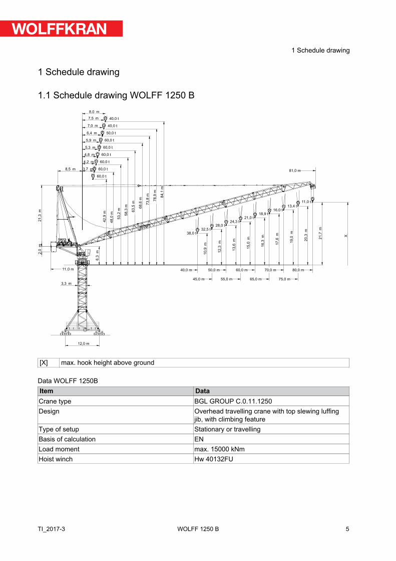
1 Schedule drawing
1.1 Schedule drawing WOLFF 1250 B6
,3m2,0
m2
1,3
m
8,5 m
21 X
,7m
10,9
m
12
,3m
13
,6m
15,0
m
16
,3m
17
,6m
19
,0m
20
,3m
3,7 m
4,2 m
4,8 m
5,3 m
6,4 m
5,9 m
7,0 m
7,5 m
8,0 m
42
,9 m
48
,0 m
53,2
m
58,3
m
63
,5 m
68,6
m
73,8
m
78
,9 m
84
,1 m
3,3 m
40,0 m 50,0 m
45,0 m 55,0 m
60,0 m
65,0 m
70,0 m
75,0 m
80,0 m
38,0 t32,5 t
28,0 t24,3 t
21,0 t18,9 t
16,0 t13,4 t
11,0 t
81,0 m
11,0 m
60,0 t
60,0 t
60,0 t
60,0 t
60,0 t
60,0 t
50,0 t
40,0 t
40,0 t
12,0 m
[X] max. hook height above ground
Data WOLFF 1250BItem DataCrane type BGL GROUP C.0.11.1250Design Overhead travelling crane with top slewing luffing
jib, with climbing featureType of setup Stationary or travellingBasis of calculation ENLoad moment max. 15000 kNmHoist winch Hw 40132FU
5
1 Schedule drawing
TI_2017-3 WOLFF 1250 B

2 Load carrying capacities
!NOTICE
WOLFF-Boost
With the WOLFF-Boost function, the load is allowed to exceed the load torquerange specified for the lifting capacities by up to 10%. This is, however, sub-ject to the restriction that hoisting gear and trolley drive (trolley crane)respectively hoisting gear and derricking gear (luffing crane) must only bemoved alternatingly.
6
2 Load carrying capacities
TI_2017-3WOLFF 1250 B

2.1 Table of load carrying capacity WOLFF 1250 B (1 fall operation)
20 t
Operating radius[m]
30 35 40 45 50 55 60 65 70 75 80
JL
[m]
80 8.0 - 52.0 20.0 20.0 20.0 20.0 20.0 18.6 16.6 14.9 13.4 12.1 11.0 LCC
[t]75 7.5 - 55.5 20.0 20.0 20.0 20.0 20.0 20.0 18.1 16.3 14.7 13.470 7.0 - 59.0 20.0 20.0 20.0 20.0 20.0 20.0 19.6 17.7 16.065 6.4 - 61.5 20.0 20.0 20.0 20.0 20.0 20.0 20.0 18.960 5.9 - 60.0 20.0 20.0 20.0 20.0 20.0 20.0 20.055 5.3 - 55.0 20.0 20.0 20.0 20.0 20.0 20.050 4.8 - 50.0 20.0 20.0 20.0 20.0 20.045 4.2 - 45.0 20.0 20.0 20.0 20.040 3.7 - 40.0 20.0 20.0 20.0
JL Jib lengthLCC Load carrying capacity
The load carrying capacity is related to a tower height of 40.5 m. Tower heights greater than that reducethe maximum load carrying capacity by the weight of the additional hoisting ropes (one fall operation =5.04 kg per meter of the hook range).
7
2 Load carrying capacities
TI_2017-3 WOLFF 1250 B

2.2 Table of load carrying capacities (kg) in meter intervals, WOLFF 1250 B(1 fall operation)
Operating radius Jib length [m] [m] 65 70 75 8051 20000 20000 20000 2000052 20000 20000 20000 2000053 20000 20000 20000 1951054 20000 20000 20000 1905055 20000 20000 20000 1860056 20000 20000 19770 1816057 20000 20000 19330 1774058 20000 20000 18910 1734059 20000 20000 18490 1695060 20000 19580 18100 1657061 20000 19170 17710 1621062 19840 18770 17340 1585063 19510 18380 16980 1551064 19200 18010 16630 1518065 18900 17650 16290 1486066 17300 15960 1455067 16960 15640 1424068 16630 15330 1395069 16310 15030 1366070 16000 14740 1339071 14460 1312072 14180 1286073 13910 1260074 13650 1236075 13400 1211076 1188077 1165078 1143079 1121080 11000
8
2 Load carrying capacities
TI_2017-3WOLFF 1250 B

2.3 Table of load carrying capacity WOLFF 1250 B (2 fall operation)
40 t
Operating radius[m]
30 35 40 45 50 55 60 65 70 75 80
JL
[m]
80 8.0 - 29.0 38.4 31.9 27.1 23.3 20.2 17.8 15.7 13.9 12.4 11.1 10.0 LCC
[t]75 7.5 - 30.5 40.0 34.0 29.0 25.0 21.9 19.3 17.1 15.3 13.8 12.470 7.0 - 32.0 40.0 36.1 30.8 26.7 23.4 20.7 18.5 16.6 15.065 6.4 - 33.0 40.0 37.4 32.1 28.0 24.7 22.0 19.8 17.960 5.9 - 34.0 40.0 38.8 33.4 29.3 26.0 23.3 21.055 5.3 - 35.0 40.0 40.0 34.6 30.4 27.1 24.350 4.8 - 36.0 40.0 40.0 35.7 31.4 28.045 4.2 - 37.0 40.0 40.0 36.8 32.540 3.7 - 38.0 40.0 40.0 38.0
JL Jib lengthLCC Load carrying capacity
The load carrying capacity is related to a tower height of 40.5 m. Tower heights greater than that reducethe maximum load carrying capacity by the weight of the additional hoisting ropes (two fall operation =10.08 kg per meter of the hook range).
9
2 Load carrying capacities
TI_2017-3 WOLFF 1250 B

2.4 Table of load carrying capacities (kg) in meter intervals, WOLFF 1250 B(2 fall operation)
Operating radius Jib length [m] [m] 40 45 50 55 60 65 70 75 8028 40000 40000 40000 40000 40000 40000 40000 40000 4000029 40000 40000 40000 40000 40000 40000 40000 40000 4000030 40000 40000 40000 40000 40000 40000 40000 40000 3843031 40000 40000 40000 40000 40000 40000 40000 39250 3696032 40000 40000 40000 40000 40000 40000 40000 37820 3559033 40000 40000 40000 40000 40000 40000 38600 36480 3430034 40000 40000 40000 40000 40000 38680 37290 35210 3308035 40000 40000 40000 40000 38750 37430 36050 34020 3193036 40000 40000 40000 38800 37560 36260 34880 32890 3085037 40000 40000 38840 37670 36440 35150 33780 31830 2983038 40000 38890 37740 36590 35380 34090 32730 30820 2885039 38970 37840 36700 35570 34380 33090 31730 29860 2793040 38000 36840 35710 34600 33420 32140 30790 28950 2706041 35880 34770 33680 32510 31240 29890 28090 2623042 34980 33880 32800 31650 30380 29040 27260 2543043 34110 33020 31970 30820 29560 28220 26480 2468044 33290 32210 31170 30030 28780 27440 25730 2396045 32500 31430 30410 29280 28030 26700 25010 2327046 30680 29680 28560 27310 25980 24330 2261047 29970 28980 27870 26630 25300 23670 2198048 29290 28310 27210 25970 24650 23040 2137049 28630 27660 26580 25340 24020 22440 2079050 28000 27050 25970 24740 23420 21860 2024051 26450 25380 24160 22840 21300 1970052 25890 24820 23600 22290 20770 1919053 25340 24280 23060 21750 20250 1869054 24810 23760 22540 21240 19760 1821055 24300 23260 22040 20740 19280 1775056 22770 21560 20260 18820 1731057 22310 21100 19800 18370 1688058 21860 20650 19360 17940 1647059 21420 20220 18930 17530 1607060 21000 19800 18510 17130 1569061 19390 18110 16740 1531062 19000 17720 16370 1495063 18620 17340 16000 1460064 18260 16970 15650 1426065 17900 16620 15310 1394066 16280 14980 1362067 15940 14660 1331068 15620 14350 1301069 15310 14040 1272070 15000 13750 1244071 13470 1216072 13190 1190073 12920 1164074 12660 1138075 12400 1114076 1090077 1066078 1044079 1022080 10000
10
2 Load carrying capacities
TI_2017-3WOLFF 1250 B

2.5 Load carrying capacity table WOLFF 1250 B (3 fall operation)
60 t
Operating radius[m]
30 35 40 45 50 55 60 65 70 75 80
JL
[m]
70 7.0 - 26.0 50.0 t 42.4 35.3 30.0 25.8 22.5 19.8 17.6 15.6 14.0 LCC
[t]65 6.4 - 22.5 60.0 t 43.5 36.5 31.2 27.0 23.8 21.1 18.8 16.960 5.9 - 23.0 44.9 37.8 32.4 28.3 25.0 22.3 20.055 5.3 - 23.5 46.1 39.0 33.6 29.4 26.0 23.350 4.8 - 24.0 47.3 40.1 34.6 30.4 27.045 4.2 - 24.5 48.5 41.2 35.8 31.540 3.7 - 25.0 49.8 42.5 37.0
JL Jib lengthLCC Load carrying capacity
The load carrying capacity is related to a tower height of 40.5 m. Tower heights greater than that reducethe maximum load carrying capacity by the weight of the additional hoisting ropes (three fall operation =15.12 kg per meter of the hook range).
11
2 Load carrying capacities
TI_2017-3 WOLFF 1250 B
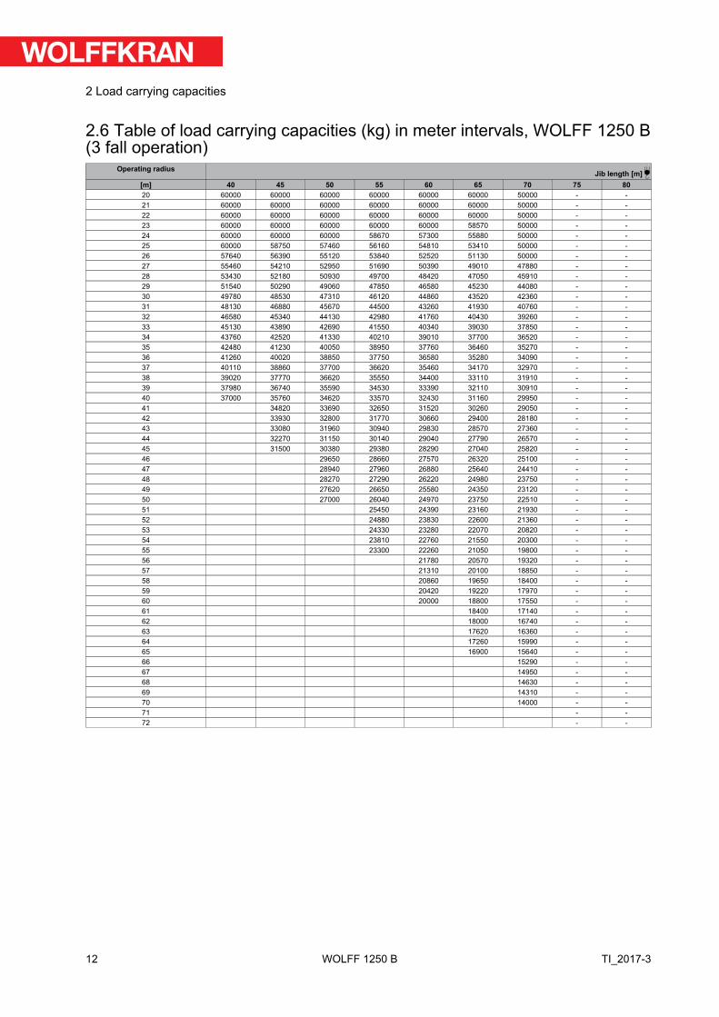
2.6 Table of load carrying capacities (kg) in meter intervals, WOLFF 1250 B(3 fall operation)
Operating radius Jib length [m] [m] 40 45 50 55 60 65 70 75 8020 60000 60000 60000 60000 60000 60000 50000 - -21 60000 60000 60000 60000 60000 60000 50000 - -22 60000 60000 60000 60000 60000 60000 50000 - -23 60000 60000 60000 60000 60000 58570 50000 - -24 60000 60000 60000 58670 57300 55880 50000 - -25 60000 58750 57460 56160 54810 53410 50000 - -26 57640 56390 55120 53840 52520 51130 50000 - -27 55460 54210 52950 51690 50390 49010 47880 - -28 53430 52180 50930 49700 48420 47050 45910 - -29 51540 50290 49060 47850 46580 45230 44080 - -30 49780 48530 47310 46120 44860 43520 42360 - -31 48130 46880 45670 44500 43260 41930 40760 - -32 46580 45340 44130 42980 41760 40430 39260 - -33 45130 43890 42690 41550 40340 39030 37850 - -34 43760 42520 41330 40210 39010 37700 36520 - -35 42480 41230 40050 38950 37760 36460 35270 - -36 41260 40020 38850 37750 36580 35280 34090 - -37 40110 38860 37700 36620 35460 34170 32970 - -38 39020 37770 36620 35550 34400 33110 31910 - -39 37980 36740 35590 34530 33390 32110 30910 - -40 37000 35760 34620 33570 32430 31160 29950 - -41 34820 33690 32650 31520 30260 29050 - -42 33930 32800 31770 30660 29400 28180 - -43 33080 31960 30940 29830 28570 27360 - -44 32270 31150 30140 29040 27790 26570 - -45 31500 30380 29380 28290 27040 25820 - -46 29650 28660 27570 26320 25100 - -47 28940 27960 26880 25640 24410 - -48 28270 27290 26220 24980 23750 - -49 27620 26650 25580 24350 23120 - -50 27000 26040 24970 23750 22510 - -51 25450 24390 23160 21930 - -52 24880 23830 22600 21360 - -53 24330 23280 22070 20820 - -54 23810 22760 21550 20300 - -55 23300 22260 21050 19800 - -56 21780 20570 19320 - -57 21310 20100 18850 - -58 20860 19650 18400 - -59 20420 19220 17970 - -60 20000 18800 17550 - -61 18400 17140 - -62 18000 16740 - -63 17620 16360 - -64 17260 15990 - -65 16900 15640 - -66 15290 - -67 14950 - -68 14630 - -69 14310 - -70 14000 - -71 - -72 - -
12
2 Load carrying capacities
TI_2017-3WOLFF 1250 B

3 Tower combinations
DANGERUsage of incorrect tower combinations.
The slewing tower crane may overturn.
1) Use the specified tower combinations.
2) If you need another tower combination that is not specified here, pleasecontact WOLFFKRAN to get an approved alternative setup in writing.
!NOTICE
All tower combinations apply to free standing slewing tower cranes withoutclimbing gear.
13
3 Tower combinations
TI_2017-3 WOLFF 1250 B
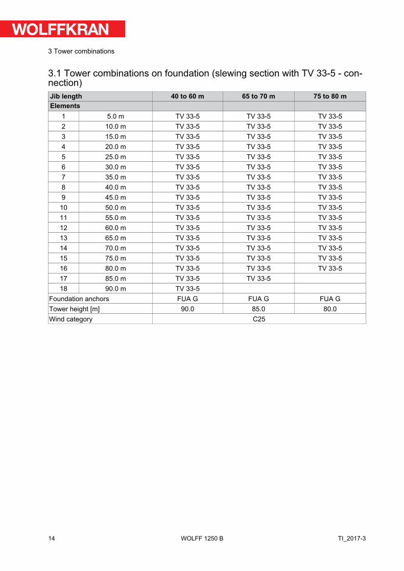
3.1 Tower combinations on foundation (slewing section with TV 33-5 - con-nection)Jib length 40 to 60 m 65 to 70 m 75 to 80 mElements
1 5.0 m TV 33-5 TV 33-5 TV 33-52 10.0 m TV 33-5 TV 33-5 TV 33-53 15.0 m TV 33-5 TV 33-5 TV 33-54 20.0 m TV 33-5 TV 33-5 TV 33-55 25.0 m TV 33-5 TV 33-5 TV 33-56 30.0 m TV 33-5 TV 33-5 TV 33-57 35.0 m TV 33-5 TV 33-5 TV 33-58 40.0 m TV 33-5 TV 33-5 TV 33-59 45.0 m TV 33-5 TV 33-5 TV 33-5
10 50.0 m TV 33-5 TV 33-5 TV 33-511 55.0 m TV 33-5 TV 33-5 TV 33-512 60.0 m TV 33-5 TV 33-5 TV 33-513 65.0 m TV 33-5 TV 33-5 TV 33-514 70.0 m TV 33-5 TV 33-5 TV 33-515 75.0 m TV 33-5 TV 33-5 TV 33-516 80.0 m TV 33-5 TV 33-5 TV 33-517 85.0 m TV 33-5 TV 33-518 90.0 m TV 33-5
Foundation anchors FUA G FUA G FUA GTower height [m] 90.0 85.0 80.0Wind category C25
14
3 Tower combinations
TI_2017-3WOLFF 1250 B

3.2 Tower combinations on cross frame element (slewing section with TV33-5 - connection)Jib length 40 to 55 m 60 to 70 m 75 to 80 mItem
1 5.0 m TV 33-5 TV 33-5 TV 33-52 10.0 m TV 33-5 TV 33-5 TV 33-53 15.0 m TV 33-5 TV 33-5 TV 33-54 20.0 m TV 33-5 TV 33-5 TV 33-55 25.0 m TV 33-5 TV 33-5 TV 33-56 30.0 m TV 33-5 TV 33-5 TV 33-57 35.0 m TV 33-5 TV 33-5 TV 33-58 40.0 m TV 33-5 TV 33-5 TV 33-59 45.0 m TV 33-5 TV 33-5 TV 33-5
10 50.0 m TV 33-5 TV 33-5 TV 33-511 55.0 m TV 33-5 TV 33-5 TV 33-512 60.0 m TV 33-5 TV 33-5 TV 33-513 65.0 m TV 33-5 TV 33-5 TV 33-514 70.0 m TV 33-5 TV 33-5 TV 33-515 75.0 m TV 33-5 TV 33-516 80.0 m TV 33-5
Substructure KRE 4120 KRE 4120 KRE 4120Corner distance [m x m] 12.0 x 12.0 12.0 x 12.0 12.0 x 12.0Substructure height [m] 8.7 8.7 8.7Tower height [m] 88.7 83.7 78.7Wind category C25
15
3 Tower combinations
TI_2017-3 WOLFF 1250 B

3.3 Tower combinations on undercarriage (slewing section with TV 33-5 -connection)Jib length 40 to 55 m 60 to 70 m 75 to 80 mItem
1 5.0 m TV 33-5 TV 33-5 TV 33-52 10.0 m TV 33-5 TV 33-5 TV 33-53 15.0 m TV 33-5 TV 33-5 TV 33-54 20.0 m TV 33-5 TV 33-5 TV 33-55 25.0 m TV 33-5 TV 33-5 TV 33-56 30.0 m TV 33-5 TV 33-5 TV 33-57 35.0 m TV 33-5 TV 33-5 TV 33-58 40.0 m TV 33-5 TV 33-5 TV 33-59 45.0 m TV 33-5 TV 33-5 TV 33-5
10 50.0 m TV 33-5 TV 33-5 TV 33-511 55.0 m TV 33-5 TV 33-5 TV 33-512 60.0 m TV 33-5 TV 33-513 65.0 m TV 33-5
Substructure UW 4120 UW 4120 UW 4120Corner distance [m x m] 12.0 x 12.0 12.0 x 12.0 12.0 x 12.0Substructure height [m] 10.0 10.0 10.0Tower height [m] 75.0 70.0 65.0Wind category C25
16
3 Tower combinations
TI_2017-3WOLFF 1250 B

4 Foundation loads / central ballast weights / corner loads in compliancewith EN 14439 / EN 13001
DANGERUsage of incorrect tower combinations.
The slewing tower crane may overturn.
1) Use the specified tower combinations.
2) If you need another tower combination that is not specified here, pleasecontact WOLFFKRAN to get an approved alternative setup in writing.
Jib positionsThe corner loads are given for two jib positions with the maximum corner load resulting from jib position 1.
For square setup, the following equation is true: a = b
For rectangular setup, the following equation is true: a > b
A B1
D Ca
b
2
Cross frame or cross frame element
A B1
D C
2
a
b
Undercarriage
NOTICE! For undercarriage details, please refer to the relevant operating manual.
Wind load with crane out of serviceThe stability for stormy weather is calculated on the basis of wind region C (EN 13001-2). The referencewind speed for zone C is 28 m/s (10 m above ground, averaged over 10 minutes).As a basis, a recur-rence interval of 25 years is used. As a basis, a recurrence interval of 25 years is used.
Please contact WOLFFKRAN for stability calculations in other wind regions.
For information on the different substructures, refer to Section 5 of the Operating Manual.
17
4 Foundation loads / central ballast weights / corner loads in compliance with EN 14439 / EN 13001
TI_2017-3 WOLFF 1250 B

4.1 Foundation loads jib 40 m - 60 mSlewing section 1250 B with 40 m – 60 m jib on foundation.Slewing tower crane without climbing device.
Foundation load in compliance with EN 14439 / EN 13001 – typical loadsIncludes all dynamical factors under consideration of second-order theory for sta-tionary slewing tower cranes on concrete foundation in compliance with a towercombination without climbing device.
H
M
V
TH: Crane in service Crane out of service AssemblySlewing torque: 750 kNm Wind category C25
M V H M V H M V H[m] [kNm] [kN] [kN] [kNm] [kN] [kN] [kNm] [kN] [kN]5.0 12280 2155 43 9090 1936 110 5070 1161 17
10.0 12520 2254 47 9690 2035 124 5160 1260 1915.0 12790 2353 51 10360 2134 137 5260 1359 2120.0 13100 2452 55 11110 2233 151 5380 1458 2425.0 13440 2551 59 11940 2332 164 5520 1557 2630.0 13820 2650 64 12850 2431 177 5670 1656 2835.0 14240 2749 68 13850 2530 190 5840 1755 3140.0 14710 2848 72 14930 2629 204 6020 1854 3345.0 15210 2947 76 16110 2728 217 6220 1953 3550.0 15760 3046 80 17390 2827 230 6440 2052 3855.0 16370 3145 84 18770 2926 243 6680 2151 4060.0 17020 3244 88 20260 3025 257 6940 2250 4265.0 17730 3343 93 21860 3124 270 7220 2349 4570.0 18510 3442 97 23590 3223 283 7520 2448 4775.0 19350 3541 101 25450 3322 296 7850 2547 4980.0 20270 3640 105 27460 3421 310 8200 2646 5285.0 21270 3739 109 29620 3520 323 8580 2745 5490.0 22360 3838 113 32050 3619 477 8990 2844 56
Caption:TH: Tower height V: Vertical loadM: Torque H: Horizontal load
18
4 Foundation loads / central ballast weights / corner loads in compliance with EN 14439 / EN 13001
TI_2017-3WOLFF 1250 B

4.2 Foundation loads jib 65 m - 70 mSlewing section 1250 B with 65 m – 70 m jib on foundation.Slewing tower crane without climbing device.
Foundation load in compliance with EN 14439 / EN 13001 – typical loadsIncludes all dynamical factors under consideration of second-order theory for sta-tionary slewing tower cranes on concrete foundation in compliance with a towercombination without climbing device.
H
M
V
TH: Crane in service Crane out of service AssemblySlewing torque: 750 kNm Wind category C25
M V H M V H M V H[m] [kNm] [kN] [kN] [kNm] [kN] [kN] [kNm] [kN] [kN]5.0 12410 2121 42 9320 1967 119 7400 1192 17
10.0 12640 2220 46 9960 2066 132 7500 1291 1915.0 12910 2319 50 10670 2165 145 7610 1390 2220.0 13210 2418 54 11460 2264 159 7740 1489 2425.0 13550 2517 58 12330 2363 172 7880 1588 2630.0 13930 2616 62 13290 2462 185 8040 1687 2935.0 14340 2715 67 14330 2561 198 8220 1786 3140.0 14800 2814 71 15470 2660 212 8420 1885 3345.0 15300 2913 75 16690 2759 225 8630 1984 3650.0 15840 3012 79 18020 2858 238 8870 2083 3855.0 16440 3111 83 19450 2957 252 9130 2182 4060.0 17080 3210 87 20990 3056 265 9410 2281 4365.0 17790 3309 92 22650 3155 278 9720 2380 4570.0 18560 3408 96 24440 3254 291 10050 2479 4775.0 19390 3507 100 26360 3353 305 10410 2578 5080.0 20300 3606 104 28580 3452 434 10800 2677 5285.0 21290 3705 108 31930 3551 458 11220 2776 54
Caption:TH: Tower height V: Vertical loadM: Torque H: Horizontal load
19
4 Foundation loads / central ballast weights / corner loads in compliance with EN 14439 / EN 13001
TI_2017-3 WOLFF 1250 B

4.3 Foundation loads jib 75 m - 80 mSlewing section 1250 B with 75 m – 80 m jib on foundation.Slewing tower crane without climbing device.
Foundation load in compliance with EN 14439 / EN 13001 – typical loadsIncludes all dynamical factors under consideration of second-order theory for sta-tionary slewing tower cranes on concrete foundation in compliance with a towercombination without climbing device.
H
M
V
TH: Crane in service Crane out of service AssemblySlewing torque: 750 kNm Wind category C25
M V H M V H M V H[m] [kNm] [kN] [kN] [kNm] [kN] [kN] [kNm] [kN] [kN]5.0 12400 2098 41 9930 1988 127 9240 1213 17
10.0 12630 2197 45 10610 2087 141 9330 1312 1915.0 12890 2296 49 11370 2186 154 9450 1411 2220.0 13190 2395 53 12210 2285 167 9580 1510 2425.0 13520 2494 58 13130 2384 180 9730 1609 2630.0 13890 2593 62 14130 2483 194 9900 1708 2935.0 14020 2582 79 15220 2582 207 10090 1807 3140.0 14530 2681 84 16410 2681 220 10300 1906 3345.0 15080 2780 88 17680 2780 233 10520 2005 3650.0 15680 2879 92 19060 2879 247 10780 2104 3855.0 16320 2978 96 20550 2978 260 11050 2203 4060.0 17020 3077 100 22150 3077 273 11350 2302 4365.0 17780 3176 104 23870 3176 287 11680 2401 4570.0 18590 3275 108 25720 3275 330 12040 2500 4775.0 19470 3374 113 28070 3374 414 12420 2599 5080.0 20420 3473 117 31220 3473 438 12840 2698 52
Caption:TH: Tower height V: Vertical loadM: Torque H: Horizontal load
20
4 Foundation loads / central ballast weights / corner loads in compliance with EN 14439 / EN 13001
TI_2017-3WOLFF 1250 B

5 Operating speedsDrive unit
[type]Operating speed
Carrying loadHook travel
distancemax.[m]
Power[kW]
Total connectedwattage [kVA]
Hw40132FU Lifting / lowering 990 132 241.0
Total connectedload at coincid-
ence factor of 0.7
0 20 40 60 80 100 120 140 160 180 190
0,00
5,00
2,90
33
10,00
15,00
20,00
25,00
Operating speed [m/min]
Lo
ad
ca
pa
cit
ies (
t)
(referred to the 8 th rope layer on drum)
Max. tower height [m] (with jib length of 80 m) 905
Drive unit[type]
Operating speedCarrying load
Hook traveldistance
max.[m]
Power[kW]
Total connectedwattage [kVA]
Hw40132FU Lifting / lowering 495 132 241.0
Total connectedload at coincid-
ence factor of 0.7
0,00
6,20
10,00
15,00
20,00
25,00
30,00
35,00
40,00
9517
45,00
0 10 30 40 50 60 70 80 90 100
Operating speed [m/min]
Lo
ad
ca
pa
cit
ies (
t)
(referred to the 8 th rope layer on drum)
Max. tower height [m] (with jib length of 80 m) 410
21
5 Operating speeds
TI_2017-3 WOLFF 1250 B

Drive unit[type]
Operating speedCarrying load
Hook traveldistance
max.[m]
Power[kW]
Total connectedwattage [kVA]
Hw40132FU Lifting / lowering 330 132 241.0
Total connectedload at coincid-
ence factor of 0.7
0,00
9,30
11 63
20,00
30,00
40,00
50,00
60,00
70,00
0 10 20 30 40 50 60 70
Operating speed [m/min]
Lo
ad
ca
pa
cit
ies (
t)
(referred to the 8 th rope layer on drum)
Max. tower height [m] (with jib length of 80 m) 245
Drive unit[type]
Operating speeds Power[kW]
Total connectedwattage [kVA]
EW 16110FU Jib luffing in / out 110 241.0
Total connectedload at coincid-
ence factor of 0.7
2,50 3,50
Operating speed [min]
Drive unit[type]
Operating speeds Power[kW]
Total connectedwattage [kVA]
SG Slewing 2 x 11 241.0
Total connectedload at coincid-
ence factor of 0.7
0,70
Operating speed [min-1]
22
5 Operating speeds
TI_2017-3WOLFF 1250 B

6 Out of service positions
WARNINGParking the jib outside the area for the out of service position.
The slewing tower crane may overturn.
► Park the jib only in the grey shaded area for the out of service position.
!NOTICE
Out of service position with smaller operating radius.
At your request, shutdown with smaller operating radius can be implementedin cases of reduced tower height or increased central ballast, and possiblyuse of a wind sail. Please contact WOLFFKRAN for information.
23
6 Out of service positions
TI_2017-3 WOLFF 1250 B

radius [ m ]
ho
ok
he
igh
t o
ve
r to
we
r [
m]
positions out of service
jib for 40 m and 45 m
position out of service
jib from 50 m
45
40
35
50
55
60
65
70
75
80
85
90
8075706560555045403530
40 mJib
45 mJib
55 mJib
50 mJib
60 mJib
65 mJib
70 mJib
75 mJib
80 mJib
positions for out of service
24
6 Out of service positions
TI_2017-3WOLFF 1250 B

7 Package list
7.1 Package list 1250 BQuantity
Description Package L [m] W [m] H [m] Weight[kg]
Volume[m³]
1 Tower head sectionupper part includingpulley block andplatforms
L B
H 11.90 2.50 2.82 13100 83.90
1 Tower head sectionbrace
L B
H 10.48 0.99 0.49 2900 5.08
1 Tower head sectionlower part
L B
H
3.33 3.79 3.53 23700 44.55
1 Connecting blockwith ladder
L B
H
4.98 2.54 2.80 7300 35.41
1 Driver's cab suspen-sion L B
H 3.58 2.23 0.56 560 4.47
1 Driver's cab
L B
H
2.26 1.45 2.30 940 7.54
1 Counterjib withstruts and platforms L B
H 9.81 2.50 1.25 8500 30.66
1 Machine platformwith luffing gear,2nd brake
L B
H
2.03 2.23 2.50 6200 11.32
1 Machine platformwith hoist gear, 2ndbrake(incl. 1000 m Ø 32mm hoisting rope =5 tons)
BL
H
4.85 2.60 2.45 17500 30.89
1 Jib element 1(without pedestals) L B
H 11.89 2.55 2.51 4400 76.10
1 Jib element 2L B
H 10.59 2.03 2.50 3100 53.74
1 Jib element 3L B
H 10.59 2.03 2.50 3200 53.74
1 Jib element 4L B
H 5.41 2.03 2.50 1600 27.46
1 Jib element 5L B
H 5.41 2.03 2.50 1600 27.46
25
7 Package list
TI_2017-3 WOLFF 1250 B
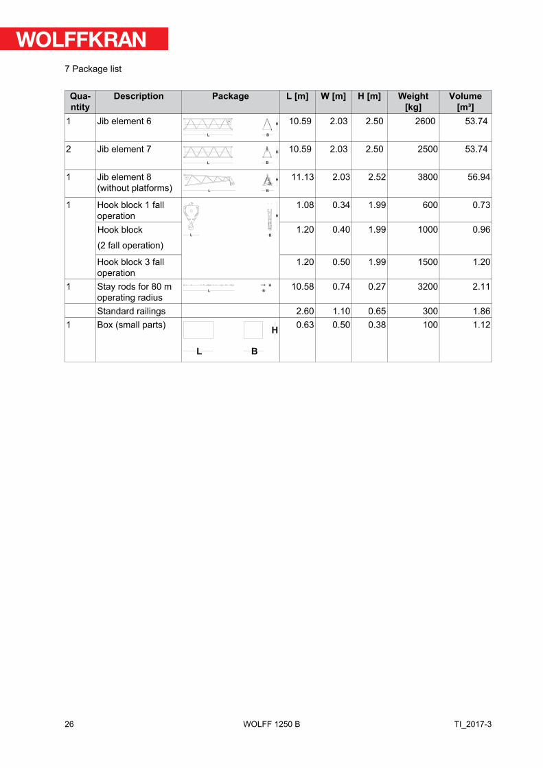
Quantity
Description Package L [m] W [m] H [m] Weight[kg]
Volume[m³]
1 Jib element 6L B
H 10.59 2.03 2.50 2600 53.74
2 Jib element 7L B
H 10.59 2.03 2.50 2500 53.74
1 Jib element 8(without platforms) L B
H 11.13 2.03 2.52 3800 56.94
1 Hook block 1 falloperation
L B
H
1.08 0.34 1.99 600 0.73
Hook block
(2 fall operation)
1.20 0.40 1.99 1000 0.96
Hook block 3 falloperation
1.20 0.50 1.99 1500 1.20
1 Stay rods for 80 moperating radius
L B
H 10.58 0.74 0.27 3200 2.11
Standard railings 2.60 1.10 0.65 300 1.861 Box (small parts)
L B
H0.63 0.50 0.38 100 1.12
26
7 Package list
TI_2017-3WOLFF 1250 B

8 Assembly weights
8.1 Counterweight blocks
!NOTICE
The described diagrams of the concrete counterweights and central ballastblocks only show sketches. Have them issue the reinforcement charts byexperts.
27
8 Assembly weights
TI_2017-3 WOLFF 1250 B

8.1.1 Counterweight block, 5.97 t
325.0
1850.0
325.0
300.0
1650.0
1950.0
2500.0
15°
200.0 ±3
40.0
R 60.0
41.0
Data counterweight block 5.97 tItem DataMaterial Material quality S235JR, max. carbon content 0.25%Max. permitted weight tolerance +/- 3 %Order number 30046411
28
8 Assembly weights
TI_2017-3WOLFF 1250 B

8.1.2 Counterweight block, 6.0 t
500
390
1000
390
500 1350 500
1505
130
2486 6
2350
1780
70 60 335 60 335 60 335 60 335 60 70
610
2350 1780
14010
10
5 260 5
880
20
880
80
130
R35
135
135
80
20
20
1350500
300
80
100 100
170 10901090
390 1000 390
30 30
45°6
100�
80
80 100
45°
R10
6
6
1
2
Data counterweight block 6.0 tItem DataMaterial Concrete, min. C 20/25Max. permitted weight tolerance +/- 3 %Order number 300473671 Component identifier2 Border protection
29
8 Assembly weights
TI_2017-3 WOLFF 1250 B

8.1.3 Counterweight block, 8.0 t
2
1
Data counterweight block 8.0 tItem DataMaterial Concrete, min. C 20/25Max. permitted weight tolerance +/- 3 %Order number 300439441 Component identifier2 Structural steel reinforcement
30
8 Assembly weights
TI_2017-3WOLFF 1250 B

8.2 Total weight jib assemblyComplete jib: mechanical parts, brace, supports, assembly brace ropes, assembly rope guides, hookblockJib length [m] Weight [kg]
WOLFF 1250 B
80.0 2980075.0 2790070.0 2670065.0 2480060.0 2360055.0 2170050.0 2040045.0 1850040.0 16600
31
8 Assembly weights
TI_2017-3 WOLFF 1250 B

8.3 Assembly weight slewing sectionModule Crane parts Weight [kg]
Tower head section upper part 15940▪ Tower head section upper part (including struts, plat-
forms and standard railings)15420
▪ Pulley block 350
▪ Shock absorber 170
Driver's cab with driver's cab suspension 1500▪ Driver's cab suspension 560
▪ Driver's cab 940
Tower head section lower part 23700▪ Lower part of tower head section 14015
▪ Slewing frame + ball race bearing 9670
Connecting block 7300Counterjib (including struts, pedestals and standard railing) 8780Machine platform hoisting gear (1000 m rope = 5 to) 17500Machine platform luffing gear 6200
32
8 Assembly weights
TI_2017-3WOLFF 1250 B

8.4 Assembly weight cross frame elementsCross frame element KRE 4120 complete 60 480
▪ Cross frame base 19 220
▪ Mast base 18 290
▪ Hinged sections with corner plates 14 080
▪ Struts 8 040
▪ Assembly platform, ladder, and small parts 850
33
8 Assembly weights
TI_2017-3 WOLFF 1250 B

8.5 Assembly weight undercarriageModule Crane part Weight [kg]Undercarriage UW 4120, complete 74 900
▪ Undercarriage base with subframe 34 500
▪ Mast base 18 290
▪ Hinged sections 11 800
▪ Struts 8 040
▪ Assembly platform, rope drum bracket, ladder, and smallparts
2 270
34
8 Assembly weights
TI_2017-3WOLFF 1250 B

8.6 Required hook height for mobile cranesFor information about the height of the WOLFF slewing tower crane, refer to Tower combinations [13].
NOTICE! During assembly, allowances must be made for level differences (mobile crane to baseof the slewing tower crane). Hook height above ground required for mobile cranes (X) = height of the WOLFF slewing tower crane (A)+ clearance of 33 m (B).
5
6
7
9
10
1
2
X
B
A
4
3
8
Exemplary illustration
[A] Height of the WOLFF slewing tower crane [B] Clearance 33 m[X] Hook height above ground required for the
mobile crane
1 Undercarriage 6 4-fall attachment (4 m with shackle) 2 Tower element 7 Jib, complete3 Counterjib, complete 8 Tower head section, complete4 Four-point lifting tackle (with shackle) 9 Tower head section lower part5 Two-point lifting tackle (3 m with shackle) 10 4-fall attachment (4 m with shackle)
(see also):▪ Tower combinations [13]
35
8 Assembly weights
TI_2017-3 WOLFF 1250 B
9 Assembly diagrams
9.1 Jib attachment diagram
!NOTICE
For jib assembly, use a 4-fall attachment (4 m with shackle).
Length of jib elementsItem Length [m]Jib element 1 11.60Jib element 2, 3, 6, 7 10.35Jib element 4, 5 5.18Jib element 8 10.35
36
9 Assembly diagrams
TI_2017-3WOLFF 1250 B
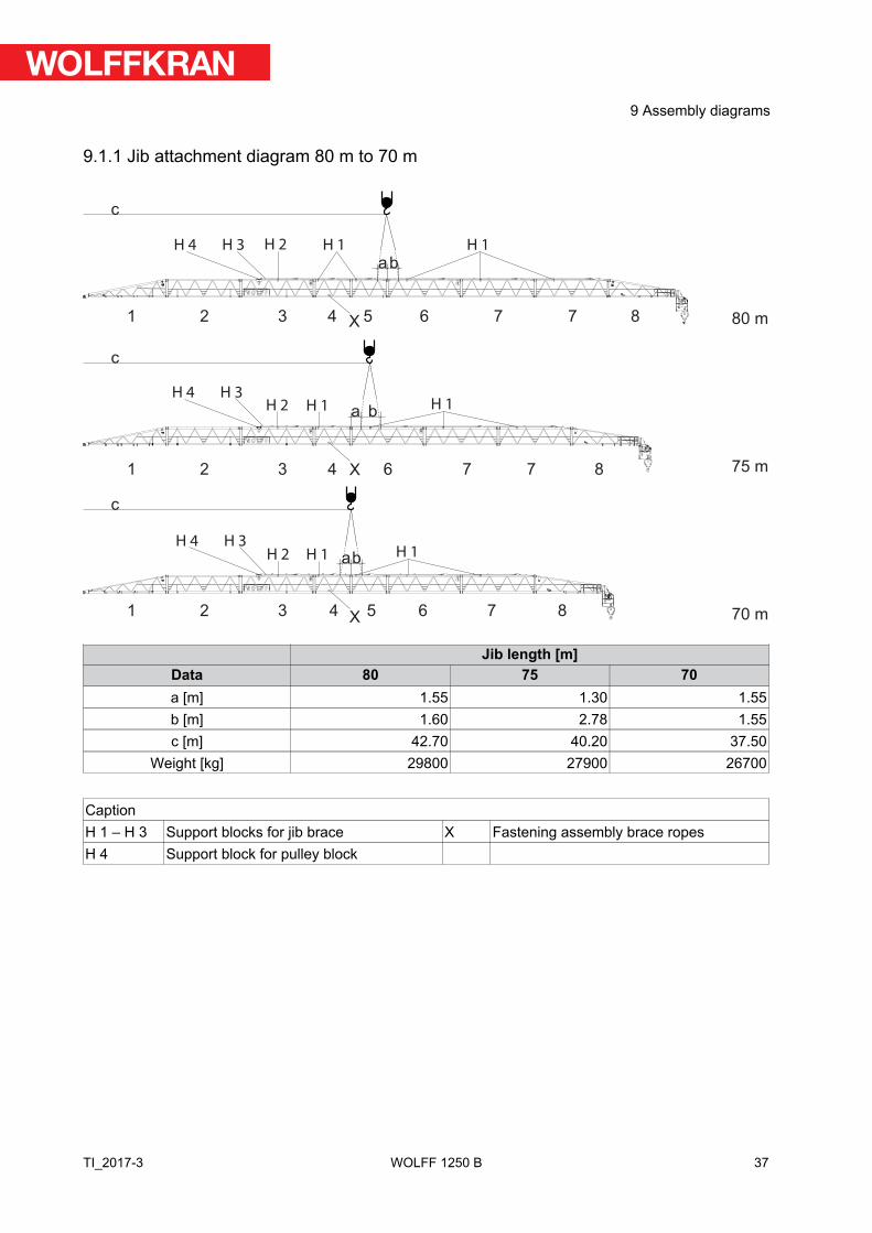
9.1.1 Jib attachment diagram 80 m to 70 m
1
1
1
2
2
2
3 4
4
4
5
5
6
6
7
7
7
6 7 7
8
8
8
3
3
a
c
b
a b
ab
c
c
80 m
75 m
70 m
H 1H 2
H 2
H 3H 4 H 1
H 1H 1
H 1H 1H 2
H 3H 4
H 3H 4
X
X
X
Jib length [m]Data 80 75 70a [m] 1.55 1.30 1.55b [m] 1.60 2.78 1.55c [m] 42.70 40.20 37.50
Weight [kg] 29800 27900 26700
CaptionH 1 – H 3 Support blocks for jib brace X Fastening assembly brace ropesH 4 Support block for pulley block
37
9 Assembly diagrams
TI_2017-3 WOLFF 1250 B
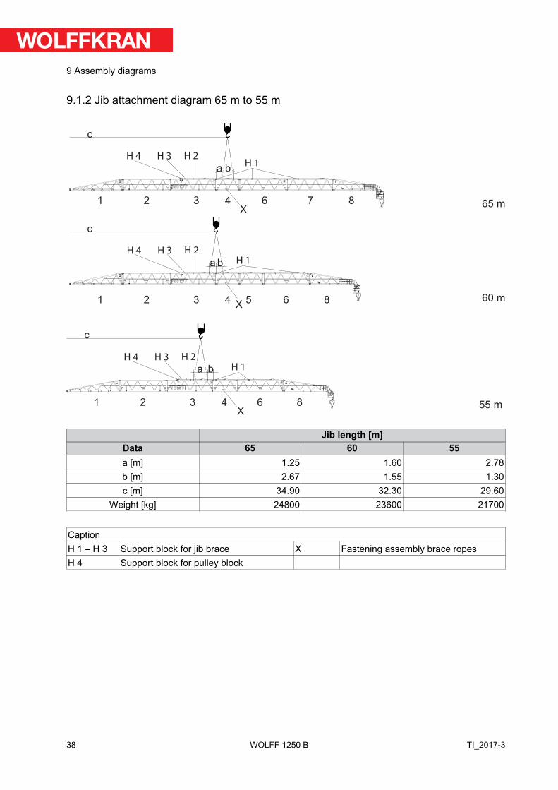
9.1.2 Jib attachment diagram 65 m to 55 m
1
1
2
2
4
4 5 6
6 7 8
8
3
3
a b
a b
c
c
65 m
60 m
6 81 2 43
a b
c
55 m
H 2H 3H 4
H 2H 3H 4
H 2H 3H 4
H 1
H 1
H 1
X
X
X
Jib length [m]Data 65 60 55a [m] 1.25 1.60 2.78b [m] 2.67 1.55 1.30c [m] 34.90 32.30 29.60
Weight [kg] 24800 23600 21700
CaptionH 1 – H 3 Support block for jib brace X Fastening assembly brace ropesH 4 Support block for pulley block
38
9 Assembly diagrams
TI_2017-3WOLFF 1250 B
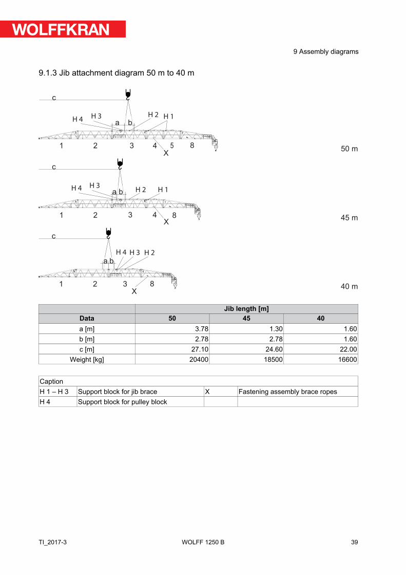
9.1.3 Jib attachment diagram 50 m to 40 m
8
8
8
1 2 43
X
1 2 43
1 2 3
a b
c
a b
c
a b
c
50 m
45 m
40 m
5
H 4H 3
H 4
H 4 H 3
H 3
H 2 H 1
H 2
H 2
H 1
X
X
Jib length [m]Data 50 45 40a [m] 3.78 1.30 1.60b [m] 2.78 2.78 1.60c [m] 27.10 24.60 22.00
Weight [kg] 20400 18500 16600
CaptionH 1 – H 3 Support block for jib brace X Fastening assembly brace ropesH 4 Support block for pulley block
39
9 Assembly diagrams
TI_2017-3 WOLFF 1250 B

9.2 Jib brace diagram1222333
80 m 12
22
33
12
23
33
12
23
3
12
33
3
133
3
133
13
12
33
75 m
70 m
65 m
60 m
55 m
50 m
45 m
40 m
Brace tableJib length Lengths [m] Total
weight[t]
Pulleyblock
Stayno. 3
Stayno. 3
Stayno. 3
Stayno. 2
Stayno. 2
Stayno. 2
Stayno. 1
Totallength
Jib – 80 m 0.88 5.15 5.15 5.15 10.30 10.30 10.30 2.48 49.71 3.2Jib – 75 m 0.88 5.15 5.15 10.30 10.30 10.30 2.48 44.56 2.8Jib – 70 m 0.88 5.15 5.15 5.15 10.30 10.30 2.48 39.41 2.6Jib – 65 m 0.88 5.15 5.15 10.30 10.30 2.48 34.26 2.2Jib – 60 m 0.88 5.15 5.15 5.15 10.30 2.48 29.11 1.9Jib – 55 m 0.88 5.15 5.15 10.30 2.48 23.96 1.6Jib – 50 m 0.88 5.15 5.15 5.15 2.48 18.81 1.3Jib – 45 m 0.88 5.15 5.15 2.48 13.66 1.0Jib – 40 m 0.88 5.15 2.48 8.51 0.6
40
9 Assembly diagrams
TI_2017-3WOLFF 1250 B

Bolt tableJib length Brace Bolts Spring retainers
Quantity Dimension [mm] Item no. Dimension [mm] Item no.Jibs - all AL 8 1 Ø115/100x350 30047094 10/60-80, galvan-
ized, yellow10022204
Jib – 80 m 1 1 Ø 90/80x220 30047082 10/60-80, galvan-ized, yellow
10022204
2 3 Ø 90/80x220 30047082 10/60-80, galvan-ized, yellow
10022204
3 3 Ø 90/80x220 30047082 10/60-80, galvan-ized, yellow
10022204
Jib – 75 m 1 1 Ø 90/80x220 30047082 10/60-80, galvan-ized, yellow
10022204
2 3 Ø 90/80x220 30047082 10/60-80, galvan-ized, yellow
10022204
3 2 Ø 90/80x220 30047082 10/60-80, galvan-ized, yellow
10022204
Jib – 70 m 1 1 Ø 90/80x220 30047082 10/60-80, galvan-ized, yellow
10022204
2 2 Ø 90/80x220 30047082 10/60-80, galvan-ized, yellow
10022204
3 3 Ø 90/80x220 30047082 10/60-80, galvan-ized, yellow
10022204
Jib – 65 m 1 1 Ø 90/80x220 30047082 10/60-80, galvan-ized, yellow
10022204
2 2 Ø 90/80x220 30047082 10/60-80, galvan-ized, yellow
10022204
3 2 Ø 90/80x220 30047082 10/60-80, galvan-ized, yellow
10022204
Jib – 60 m 1 1 Ø 90/80x220 30047082 10/60-80, galvan-ized, yellow
10022204
2 1 Ø 90/80x220 30047082 10/60-80, galvan-ized, yellow
10022204
3 3 Ø 90/80x220 30047082 10/60-80, galvan-ized, yellow
10022204
Jib – 180' 5-1/2''(55 m)
1 1 Ø 90/80x220 30047082 10/60-80, galvan-ized, yellow
10022204
2 1 Ø 90/80x220 30047082 10/60-80, galvan-ized, yellow
10022204
3 2 Ø 90/80x220 30047082 10/60-80, galvan-ized, yellow
10022204
Jib – 50 m 1 1 Ø 90/80x220 30047082 10/60-80, galvan-ized, yellow
10022204
2 - Ø 90/80x220 30047082 10/60-80, galvan-ized, yellow
10022204
3 3 Ø 90/80x220 30047082 10/60-80, galvan-ized, yellow
10022204
Jib – 45 m 1 1 Ø 90/80x220 30047082 10/60-80, galvan-ized, yellow
10022204
41
9 Assembly diagrams
TI_2017-3 WOLFF 1250 B

Jib length Brace Bolts Spring retainersQuantity Dimension [mm] Item no. Dimension [mm] Item no.
Jib – 45 m 2 - Ø 90/80x220 30047082 10/60-80, galvan-ized, yellow
10022204
3 2 Ø 90/80x220 30047082 10/60-80, galvan-ized, yellow
10022204
Jib – 40 m 1 1 Ø 90/80x220 30047082 10/60-80, galvan-ized, yellow
10022204
2 - Ø 90/80x220 30047082 10/60-80, galvan-ized, yellow
10022204
3 1 Ø 90/80x220 30047082 10/60-80, galvan-ized, yellow
10022204
42
9 Assembly diagrams
TI_2017-3WOLFF 1250 B

9.3 Arrangement of standard railings
9.3.1 Standard railings (NG) and accessories
Quantity Standard railings (NG)4 Standard post (NP)9 Standard railing 500
11 Standard railing 7502 Standard railing 15001 Standard railing 1500-S2 Standard railing 20003 Standard railing 2500
43
9 Assembly diagrams
TI_2017-3 WOLFF 1250 B

9.3.2 Arrangement of standard railings
NG 500
NG
50
0
NG
75
0
NG
75
0
NG 750
NG 500
NP Ø42,4x1090
NG 750
NG 2000
NG 2000 NG 2500 NG 1500-S
NP Ø42,4x1090
Arrangement of standard railings, counterjib
NG
50
0N
G 7
50
NG 750 NG 1500
NG
50
0
Arrangement of standard railings, driver's cab
44
9 Assembly diagrams
TI_2017-3WOLFF 1250 B

NG 2500NG 750
NG
15
00
NG
25
00
NP Ø42,4x1090
NP Ø42,4x1090
Arrangement of standard railings, slewing frame
NG 500NG 750
NG 750
NG 500
NG 500NG 750
Arrangement of standard railings, tower head section
45
9 Assembly diagrams
TI_2017-3 WOLFF 1250 B

NG 500 NG 750
��
Arrangement of standard railings, connecting block
46
9 Assembly diagrams
TI_2017-3WOLFF 1250 B

9.4 Support blocks for brace
100 mm
1
2
3
Support block H 1 for jib brace
1 Support block 3 Bracket2 Nut and washer
100 mm
1
2
3
Support block H 2 for jib brace
1 Support block 3 Bracket2 Nut and washer
100 mm
2
1
3
4
Support block H 3 for jib brace
1 Support block 3 Bracket2 Nut and washer 4 Bolts with handle and chain
47
9 Assembly diagrams
TI_2017-3 WOLFF 1250 B
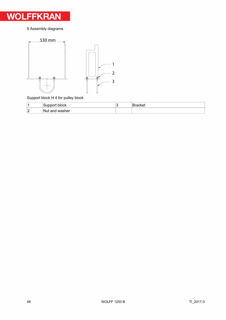
530 mm
1
2
3
Support block H 4 for pulley block
1 Support block 3 Bracket2 Nut and washer
48
9 Assembly diagrams
TI_2017-3WOLFF 1250 B
10 Suitable climbing devices
This section contains information on
▪ Outer climbing devices (KWH)▪ Inner climbing devices (KSH)
!NOTICE
Details on the climbing device
Always refer to the details in the documentation of the climbing device.
!NOTICE
The operating radius specified is measured from the tower center and is to beconsidered a reference value. Exact balancing can be achieved by changingthe operating radius with the tower elements or loads specified in the table.
!NOTICE
Details for climbing balancing
The climbing balancing details obtain to the double reeving hook blockwhich includes that the Hook position is on the same height as at hookheights in height of the bottom edge of the tower head section lower part(hook height = tower height).
!NOTICE
If feasible, preferably operate your climbing device without balancing weight.
49
10 Suitable climbing devices
TI_2017-3 WOLFF 1250 B

10.1 Outer climbing devices
DANGERClimbing device attached to the lower part of the tower head section lowerpart.
Increased wind surface. The slewing tower crane may overturn.
► Dismantle the climbing device after the climbing procedure is finished orlower the climbing device down on the ground or lower the climbingdevice down to the uppermost tower brace.
!NOTICE
Tower element on the transfer carriage
The data on climbing balance was specified under the assumption that atower element is on the transfer carriage.
50
10 Suitable climbing devices
TI_2017-3WOLFF 1250 B

10.1.1 Outer climbing unit KWH 33
Climbing radius for the balancing weightsJib length [m]
1250 B 80 75 70 65 60 55 50 45 40no weight 64.9 68.0 - - - - - - -Weight = 5.00 t - - 50.7 52.6 53.6TV 33 = 9.45 t - - - - - 44.6 45.2 - -Weight = 15.00 t - - - - - - - 38.2 -Weight = 17.00 t - - - - - - - - 36.6
51
10 Suitable climbing devices
TI_2017-3 WOLFF 1250 B

11 Arrangement of counterweight blocksJib length[m]
80 75 70 65 60 55 50 45 40
Total weight75.76 t
5,97 to St.
8 to Bt.
6 to Bt.
5,97 to St.
6 to Bt.
8 to B
t.
8 x 5.97 tons suspended steel weight2 x 8 tons suspended concrete weight2 x 6 tons lying concrete weight
52
11 Arrangement of counterweight blocks
TI_2017-3WOLFF 1250 B


WOLFFKRAN GroupHeadquarter international:
WOLFFKRAN AGBaarermattstraße 6
CH-6300 Zug
Switzerland
Phone +41 41 766 85 00
Fax +41 41 766 85 99
Manufacturing:
WOLFFKRAN GmbHAustraße 72
D-74076 Heilbronn
Germany
Phone + 49 7131 9815 0
Fax + 49 7131 9815 355
WOLFFKRAN Werk Brandenburg GmbHFrederik-Ipsen-Straße 5
D-15926 Luckau OT Alterno
Germany
Phone + 49 35456 674 0
Fax + 49 35456 674 200
www.wolffkran.com