slide 1 agenda introduction to traffic engineering brief history vocabulary requirements for...
Post on 21-Dec-2015
216 views
TRANSCRIPT
Slide 1
AgendaAgenda
Introduction to traffic engineering Brief history Vocabulary Requirements for Traffic Engineering Basic Examples
Signaling LSPs with RSVP RSVP signaling protocol RSVP objects Extensions to RSVP
Slide 2
AgendaAgenda
Constraint-based traffic engineering Extensions to IS-IS and OSPF Traffic Engineering Database User defined constraints Path section using CSPF algorithm
Traffic protection Secondary LSPs Hot-standby LSPs Fast Reroute
Slide 3
AgendaAgenda
Advanced traffic engineering features Circuit cross connect (CCC) IGP Shortcuts Configuring for transit traffic Configuring for internal destinations
Slide 4
Why Engineer Traffic?Why Engineer Traffic?
What problem are we trying to solve with Traffic Engineering?
Slide 5
Brief HistoryBrief History
Early 1990’s Internet core was connected with T1
and T3 links between routers Only a handful of routers and links to
manage and configure Humans could do the work manually IGP (Interior Gateway Protocol)
Metric-based traffic control was sufficient
Slide 6
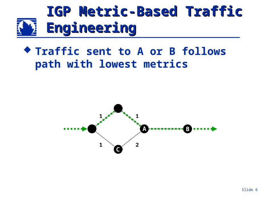
IGP Metric-Based Traffic IGP Metric-Based Traffic EngineeringEngineering
Traffic sent to A or B follows path with lowest metrics
1 1
1 2
A B
C
Slide 7
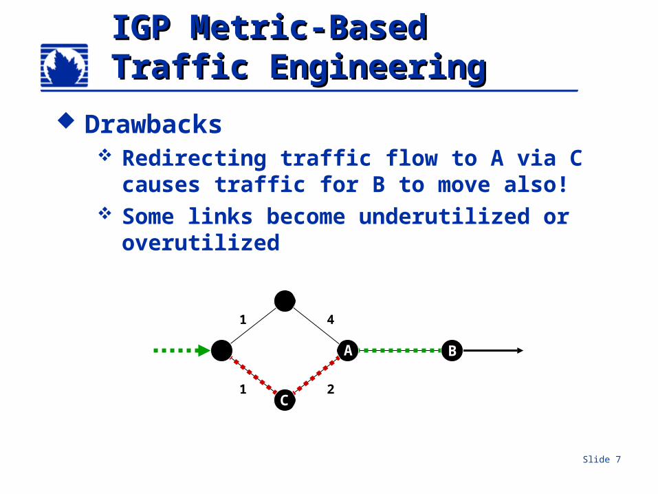
IGP Metric-BasedIGP Metric-BasedTraffic EngineeringTraffic Engineering
Drawbacks Redirecting traffic flow to A via C
causes traffic for B to move also! Some links become underutilized or
overutilized
1 4
1 2
A B
C
Slide 8
IGP Metric-BasedIGP Metric-BasedTraffic EngineeringTraffic Engineering
Drawbacks Only serves to move problem around
Some links underutilized Some links overutilized
Lacks granularity All traffic follows the IGP shortest path
Continuously adjusting IGP metrics adds instability to the network
Slide 9
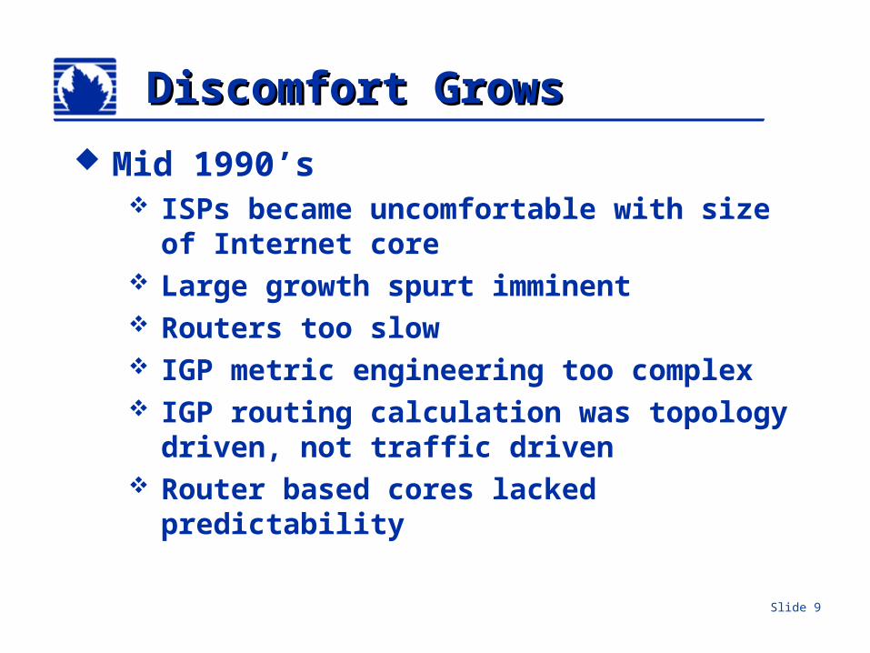
Discomfort GrowsDiscomfort Grows
Mid 1990’s ISPs became uncomfortable with size
of Internet core Large growth spurt imminent Routers too slow IGP metric engineering too complex IGP routing calculation was topology
driven, not traffic driven Router based cores lacked
predictability
Slide 10
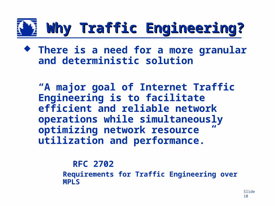
Why Traffic Engineering?Why Traffic Engineering? There is a need for a more granular
and deterministic solution
“A major goal of Internet Traffic Engineering is to facilitate efficient and reliable network operations while simultaneously optimizing network resource utilization and performance.”
RFC 2702Requirements for Traffic Engineering over MPLS
Slide 11
Overlay Networks are Overlay Networks are BornBorn
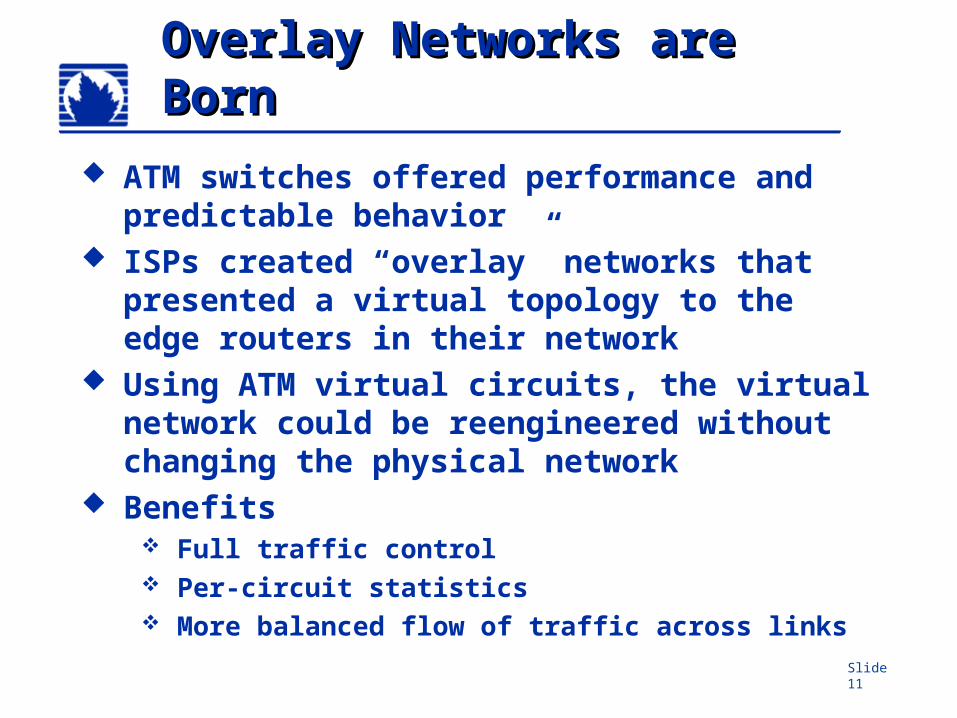
ATM switches offered performance and predictable behavior
ISPs created “overlay” networks that presented a virtual topology to the edge routers in their network
Using ATM virtual circuits, the virtual network could be reengineered without changing the physical network
Benefits Full traffic control Per-circuit statistics More balanced flow of traffic across links
Slide 12
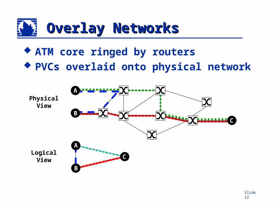
Overlay NetworksOverlay Networks
ATM core ringed by routers PVCs overlaid onto physical network
PhysicalView
A
BC
A
B
CLogicalView
Slide 13
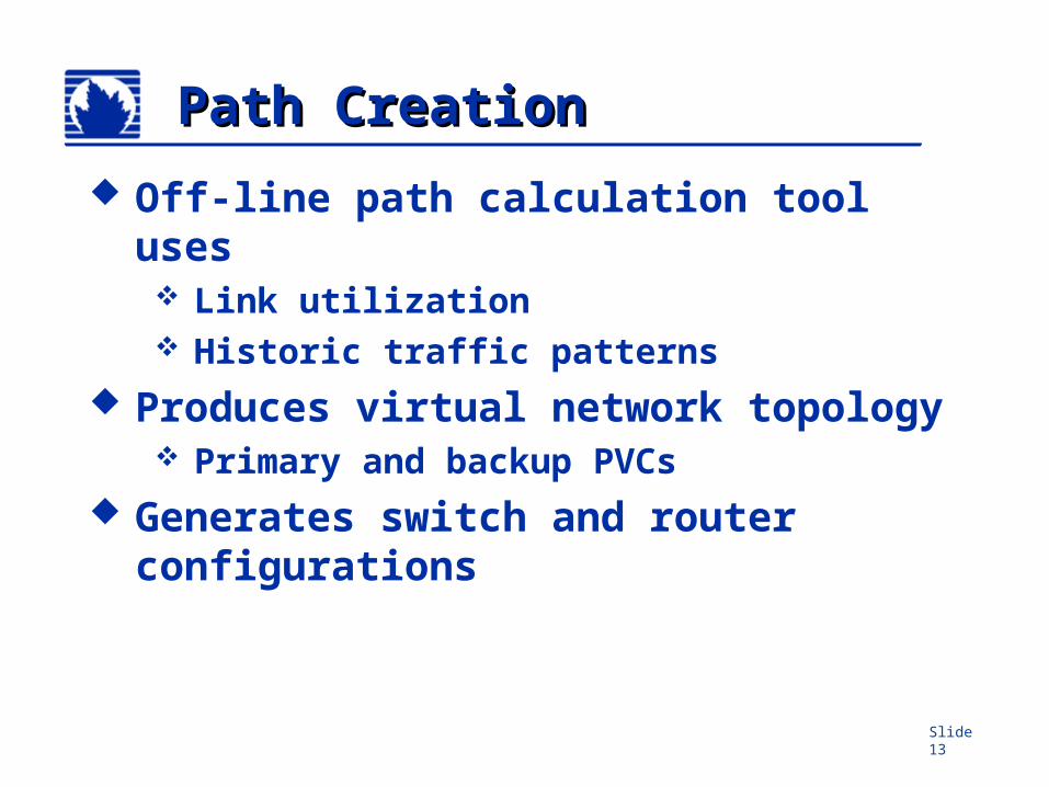
Path CreationPath Creation
Off-line path calculation tool uses Link utilization Historic traffic patterns
Produces virtual network topology Primary and backup PVCs
Generates switch and router configurations
Slide 14
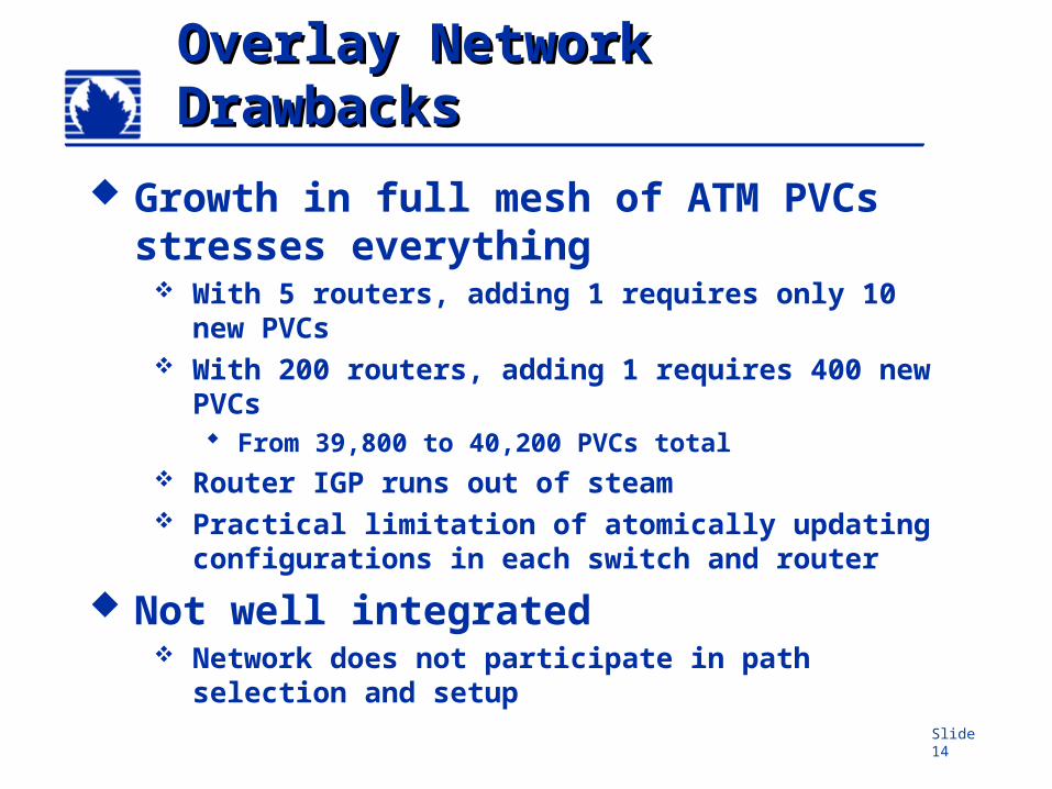
Overlay Network Overlay Network DrawbacksDrawbacks
Growth in full mesh of ATM PVCs stresses everything
With 5 routers, adding 1 requires only 10 new PVCs
With 200 routers, adding 1 requires 400 new PVCs From 39,800 to 40,200 PVCs total
Router IGP runs out of steam Practical limitation of atomically updating
configurations in each switch and router
Not well integrated Network does not participate in path
selection and setup
Slide 15
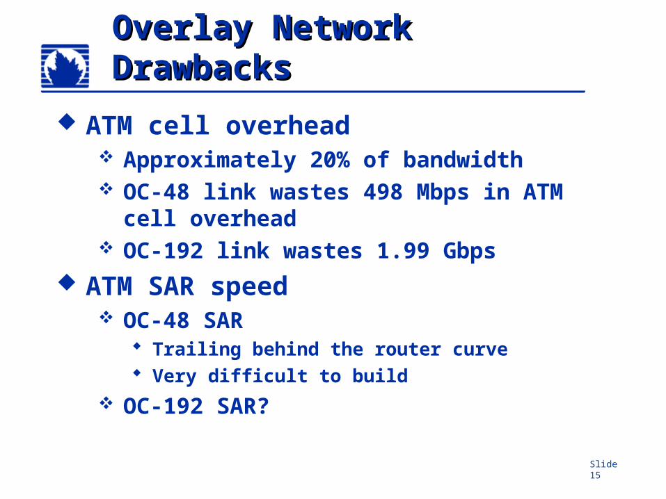
Overlay Network Overlay Network DrawbacksDrawbacks
ATM cell overhead Approximately 20% of bandwidth OC-48 link wastes 498 Mbps in ATM
cell overhead OC-192 link wastes 1.99 Gbps
ATM SAR speed OC-48 SAR
Trailing behind the router curve Very difficult to build
OC-192 SAR?
Slide 16
Routers Caught UpRouters Caught Up
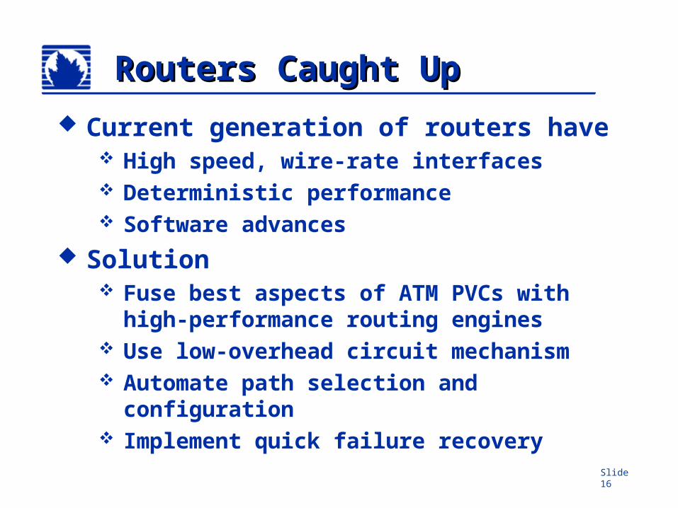
Current generation of routers have High speed, wire-rate interfaces Deterministic performance Software advances
Solution Fuse best aspects of ATM PVCs with
high-performance routing engines Use low-overhead circuit mechanism Automate path selection and
configuration Implement quick failure recovery
Slide 17
Benefits of MPLSBenefits of MPLS
Low-overhead virtual circuits for IP Originally designed to make routers faster
Fixed label lookup faster than longest match used by IP routing
Not true anymore! Value of MPLS is now in traffic
engineering One, integrated network Same forwarding mechanism can
support multiple applications Traffic Engineering, VPNs, etc….
Slide 18
What are the What are the fundamental fundamental requirements?requirements?
RFC 2702 Requirement for Traffic Engineering over
MPLS
Requirements Control Measure Characterize Integrate routing and switching All at a lower cost
Slide 19
Fundamental Fundamental RequirementsRequirements
Need the ability to: Map traffic to an LSP Monitor and measure traffic Specify explicit path of an LSP
Partial explicit route Full explicit route
Characterize an LSP Bandwidth Priority/ Preemption Affinity (Link Colors)
Reroute or select an alternate LSP
Slide 20
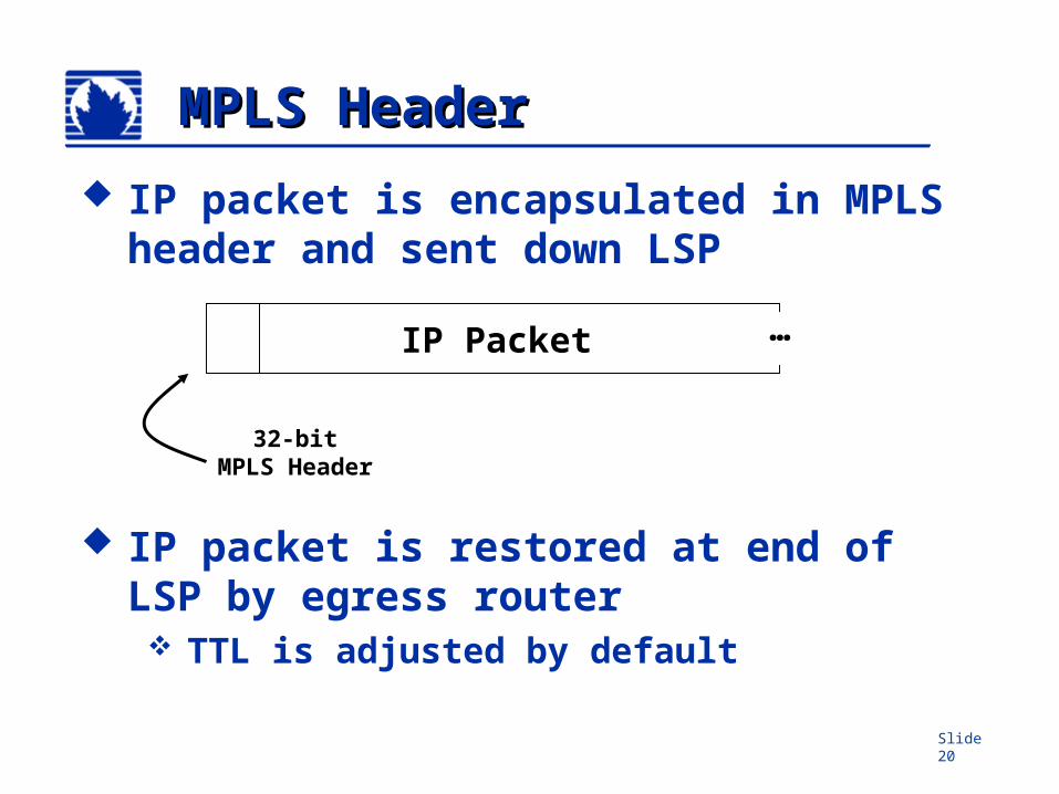
MPLS HeaderMPLS Header
IP packet is encapsulated in MPLS header and sent down LSP
IP packet is restored at end of LSP by egress router TTL is adjusted by default
…IP Packet
32-bitMPLS Header
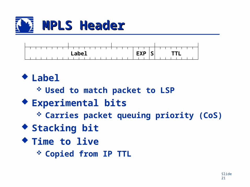
Slide 21
MPLS HeaderMPLS Header
Label Used to match packet to LSP
Experimental bits Carries packet queuing priority (CoS)
Stacking bit Time to live
Copied from IP TTL
TTLLabel EXP S
Slide 22
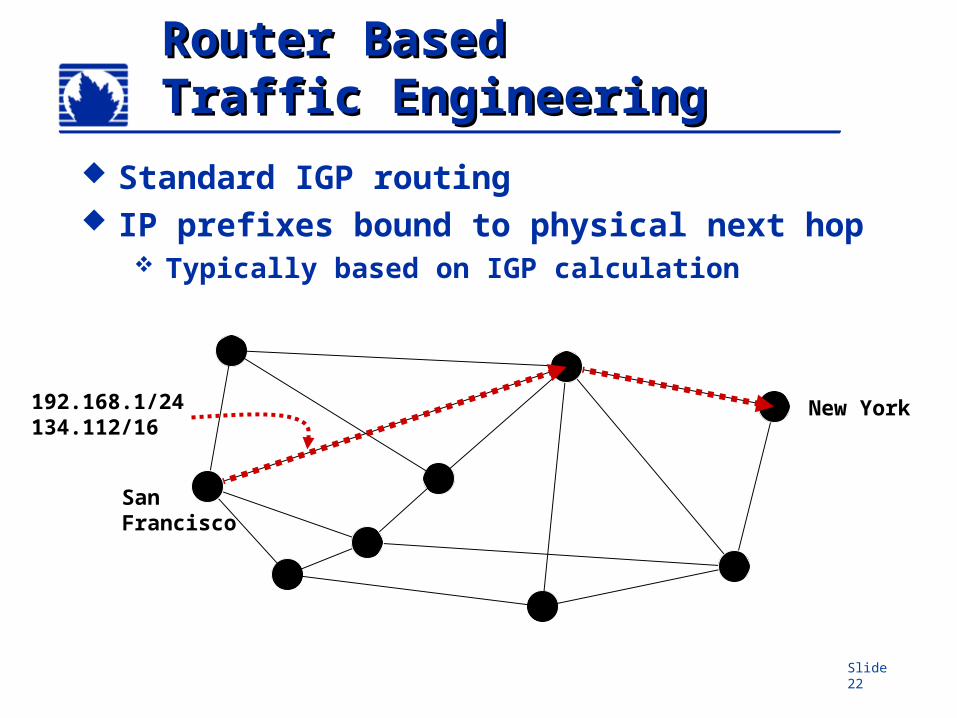
Router BasedRouter BasedTraffic EngineeringTraffic Engineering
Standard IGP routing IP prefixes bound to physical next hop
Typically based on IGP calculation
SanFrancisco
New York192.168.1/24134.112/16
Slide 23
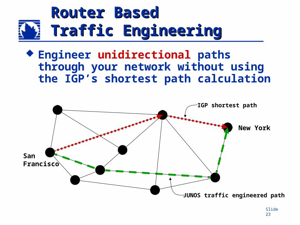
Router BasedRouter BasedTraffic EngineeringTraffic Engineering
Engineer unidirectional paths through your network without using the IGP’s shortest path calculation
SanFrancisco
IGP shortest path
JUNOS traffic engineered path
New York
Slide 24
Router BasedRouter BasedTraffic EngineeringTraffic Engineering
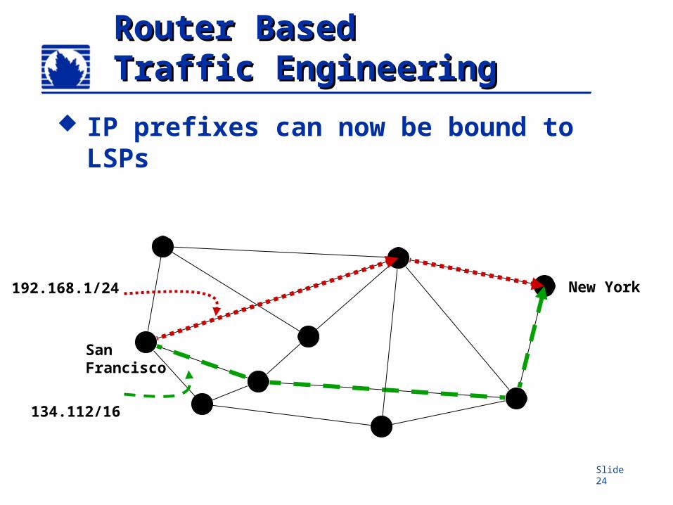
IP prefixes can now be bound to LSPs
SanFrancisco
New York192.168.1/24
134.112/16
Slide 25
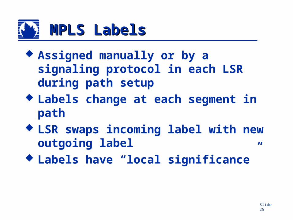
MPLS LabelsMPLS Labels
Assigned manually or by a signaling protocol in each LSR during path setup
Labels change at each segment in path
LSR swaps incoming label with new outgoing label
Labels have “local significance”
Slide 26
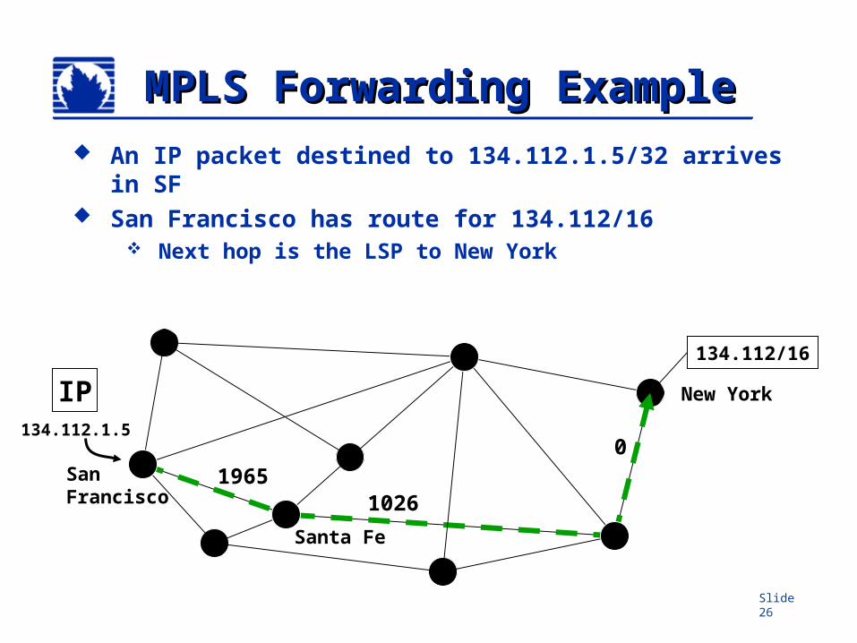
MPLS Forwarding MPLS Forwarding ExampleExample
An IP packet destined to 134.112.1.5/32 arrives in SF
San Francisco has route for 134.112/16 Next hop is the LSP to New York
SanFrancisco
New YorkIP
Santa Fe
134.112/16
134.112.1.5
19651026
0
Slide 27
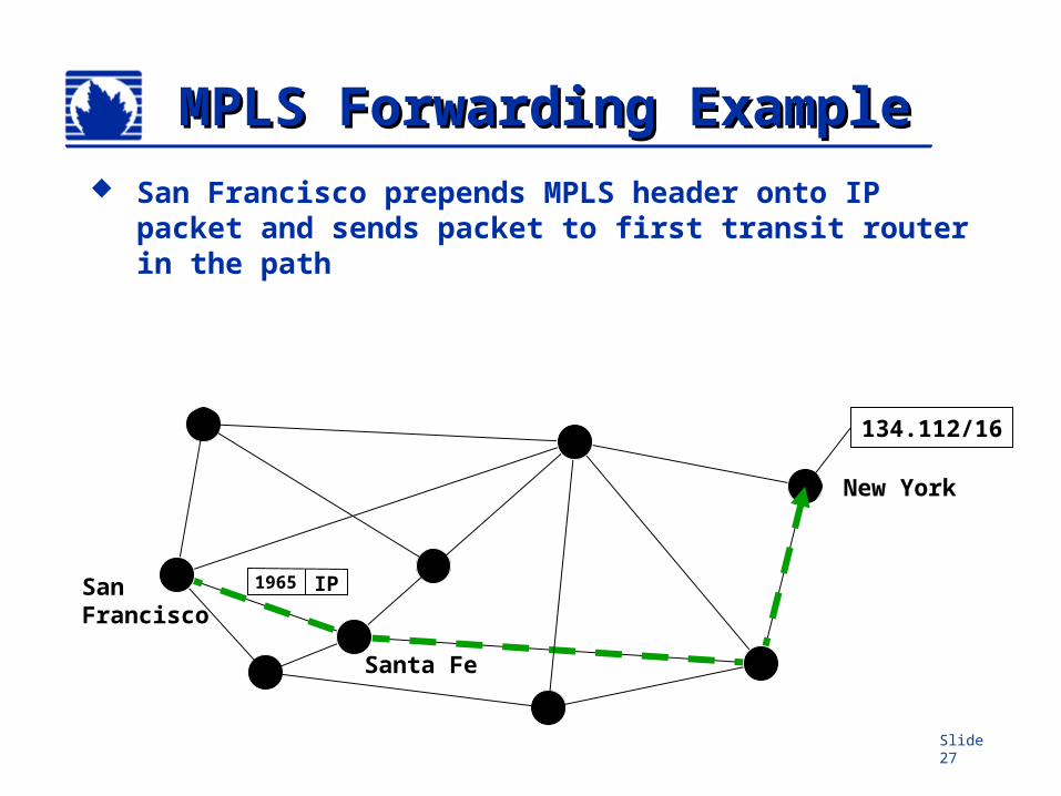
MPLS Forwarding MPLS Forwarding ExampleExample
San Francisco prepends MPLS header onto IP packet and sends packet to first transit router in the path
SanFrancisco
New York
Santa Fe
134.112/16
IP1965
Slide 28
MPLS Forwarding MPLS Forwarding ExampleExample
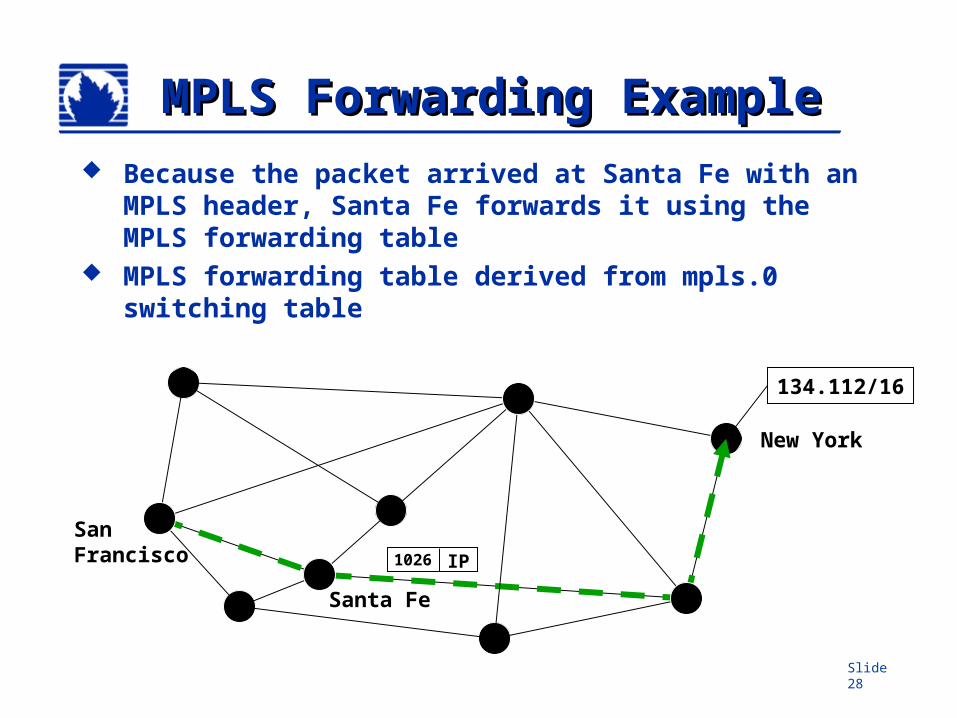
Because the packet arrived at Santa Fe with an MPLS header, Santa Fe forwards it using the MPLS forwarding table
MPLS forwarding table derived from mpls.0 switching table
SanFrancisco
New York
Santa Fe
134.112/16
IP1026
Slide 29
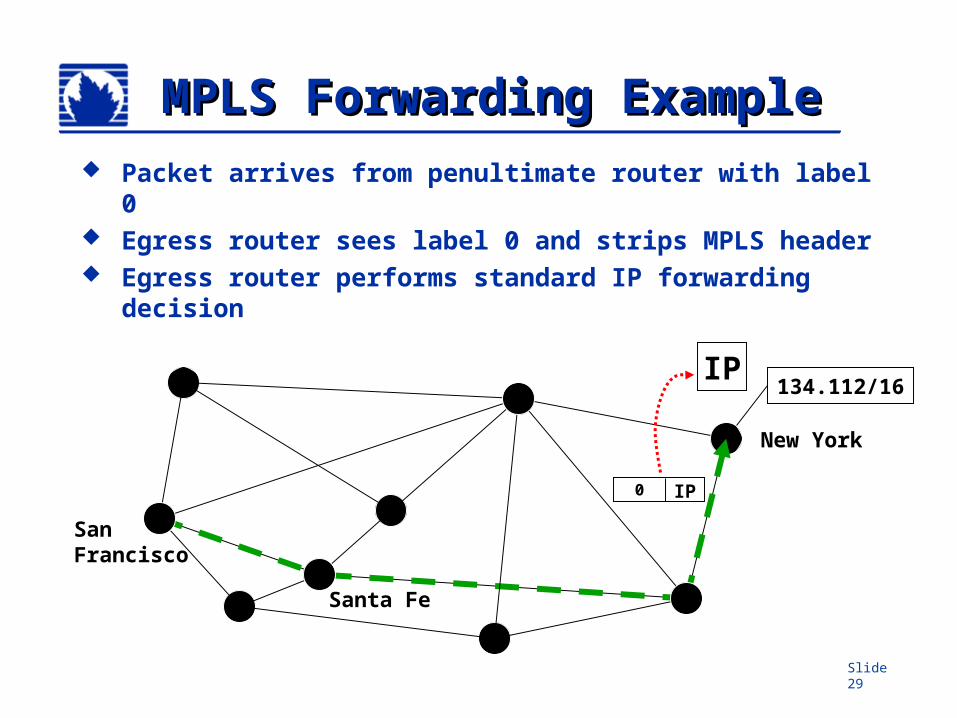
MPLS Forwarding MPLS Forwarding ExampleExample
Packet arrives from penultimate router with label 0 Egress router sees label 0 and strips MPLS header Egress router performs standard IP forwarding
decision
SanFrancisco
New York
Santa Fe
IP134.112/16
IP0
Slide 30
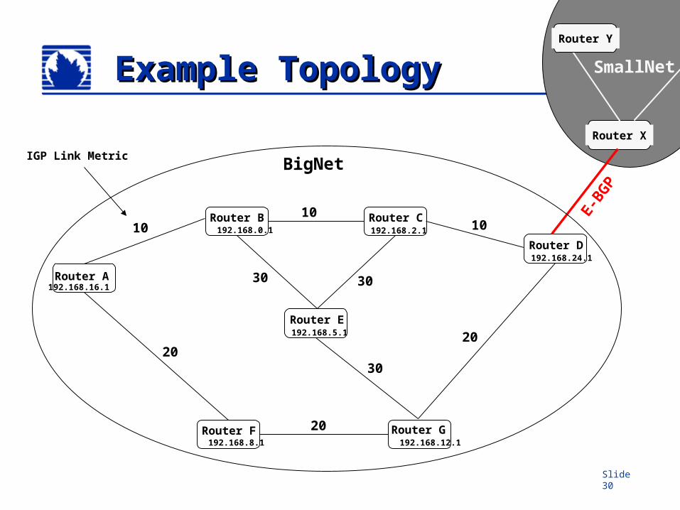
Example Topology Example Topology
Router B Router C
Router E
Router D
Router GRouter F
192.168.16.1
192.168.0.1 192.168.2.1
192.168.5.1
192.168.8.1 192.168.12.1
192.168.24.1
Router A
BigNet
Router X
SmallNet
Router Y
1010 10
20
20
20
3030
E-BGP
30
IGP Link Metric
Slide 31
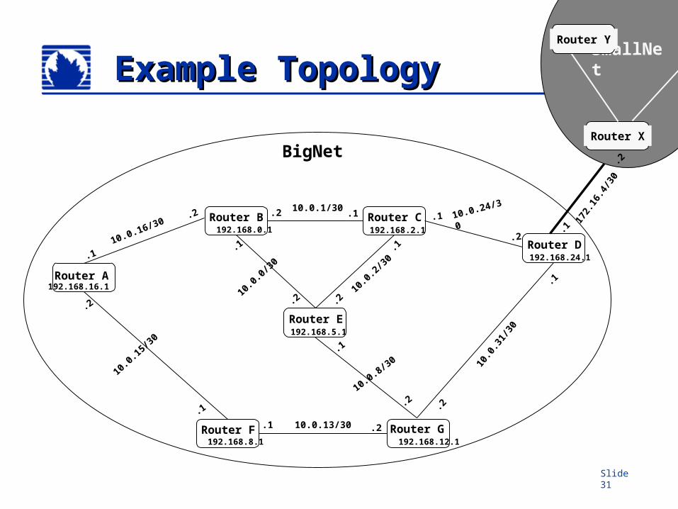
Router B Router C
Router E
Router D
.2
.1
.2.1
10.0
.31/
30
Router GRouter F
192.168.16.1
192.168.0.1 192.168.2.1
192.168.5.1
192.168.8.1 192.168.12.1
192.168.24.1
Router A.1
.2
10.0.13/30
10.0.0/30
10.0.24/30.1
.2
10.0.1/30.1.2
10.0.8/30
.1
.210
.0.2
/30
.1
.2
10.0.16/30.2
.1
10.0.15/30
.2
.1
BigNetRouter X
SmallNet
Router Y
Example TopologyExample Topology
172.
16.4
/30
.2
.1
Slide 32
Static vs Signaled LSPsStatic vs Signaled LSPs Static LSPs
Are ‘nailed up’ manually Have manually assigned MPLS labels Needs configuration on each router Do not re-route when a link fails
Signaled LSPs Signaled by RSVP Have dynamically assigned MPLS labels Configured on ingress router only Can re-route around failures
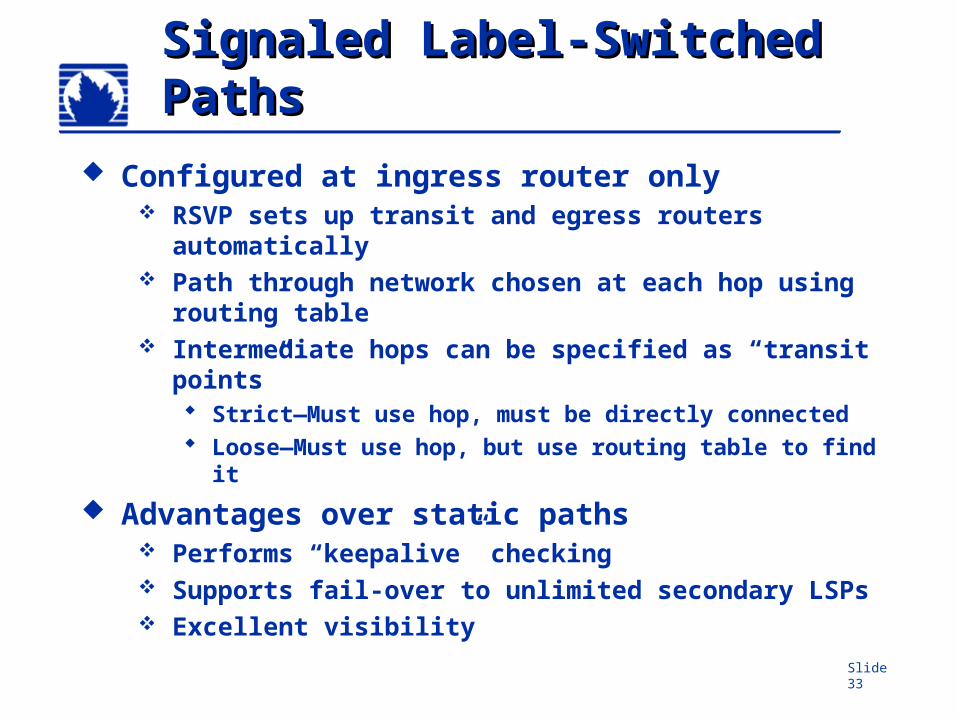
Slide 33
Signaled Label-Switched Signaled Label-Switched PathsPaths
Configured at ingress router only RSVP sets up transit and egress routers
automatically Path through network chosen at each hop using
routing table Intermediate hops can be specified as “transit
points” Strict—Must use hop, must be directly connected Loose—Must use hop, but use routing table to find
it
Advantages over static paths Performs “keepalive” checking Supports fail-over to unlimited secondary LSPs Excellent visibility
Slide 34
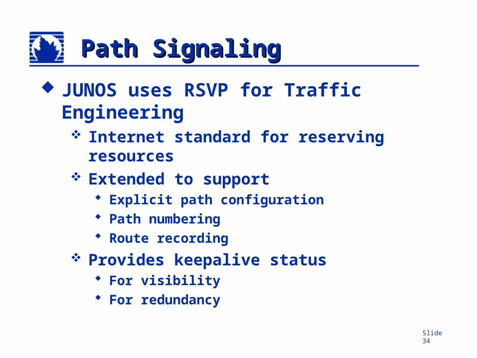
Path SignalingPath Signaling
JUNOS uses RSVP for Traffic Engineering Internet standard for reserving
resources Extended to support
Explicit path configuration Path numbering Route recording
Provides keepalive status For visibility For redundancy
Slide 35
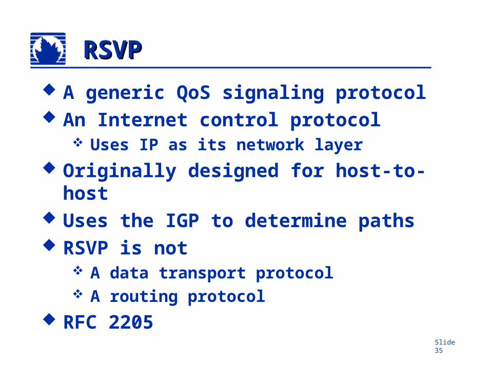
RSVPRSVP
A generic QoS signaling protocol An Internet control protocol
Uses IP as its network layer Originally designed for host-to-host Uses the IGP to determine paths RSVP is not
A data transport protocol A routing protocol
RFC 2205
Slide 36
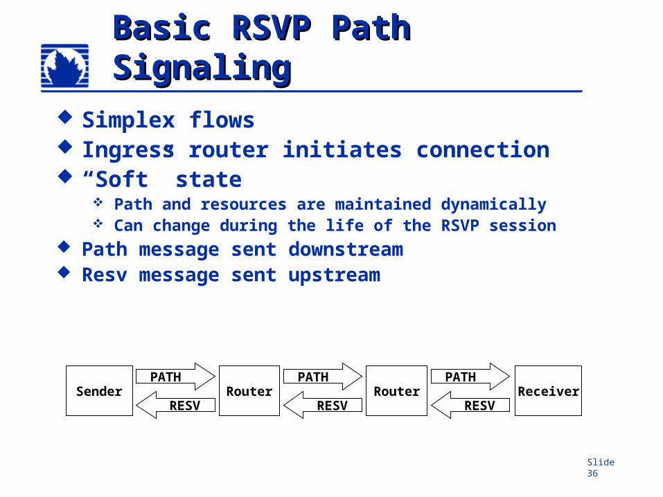
Basic RSVP Path Basic RSVP Path SignalingSignaling
Sender ReceiverRouterRouter
Simplex flows Ingress router initiates connection “Soft” state
Path and resources are maintained dynamically Can change during the life of the RSVP session
Path message sent downstream Resv message sent upstream
PATH
RESV
PATH
RESV
PATH
RESV
Slide 37
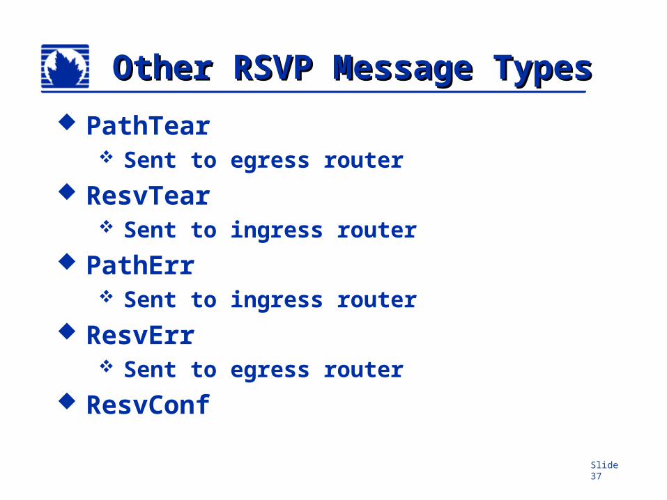
Other RSVP Message Other RSVP Message TypesTypes
PathTear Sent to egress router
ResvTear Sent to ingress router
PathErr Sent to ingress router
ResvErr Sent to egress router
ResvConf
Slide 38
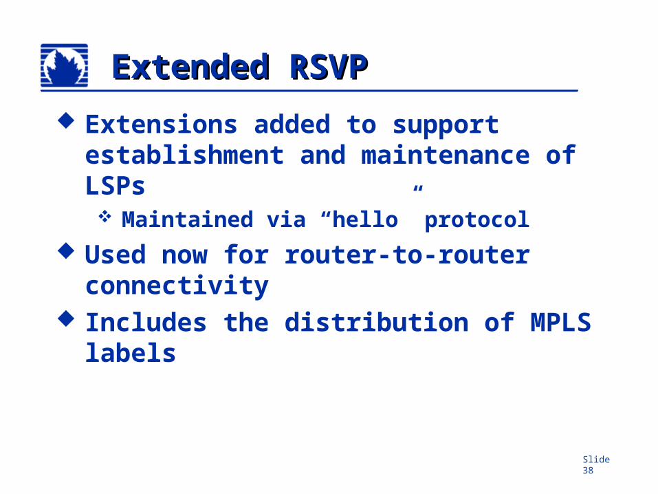
Extended RSVPExtended RSVP
Extensions added to support establishment and maintenance of LSPs Maintained via “hello” protocol
Used now for router-to-router connectivity
Includes the distribution of MPLS labels
Slide 39
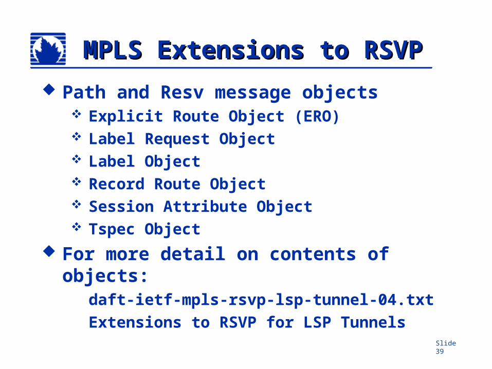
MPLS Extensions to RSVPMPLS Extensions to RSVP
Path and Resv message objects Explicit Route Object (ERO) Label Request Object Label Object Record Route Object Session Attribute Object Tspec Object
For more detail on contents of objects:
daft-ietf-mpls-rsvp-lsp-tunnel-04.txtExtensions to RSVP for LSP Tunnels
Slide 40
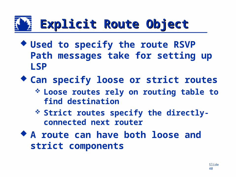
Explicit Route ObjectExplicit Route Object
Used to specify the route RSVP Path messages take for setting up LSP
Can specify loose or strict routes Loose routes rely on routing table to
find destination Strict routes specify the directly-
connected next router A route can have both loose and
strict components
Slide 41
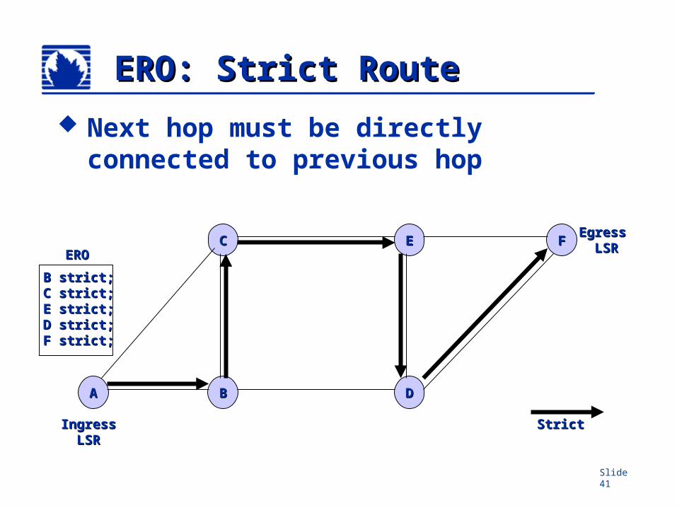
ERO: Strict RouteERO: Strict Route
AA
FFEE
DD
CC
BB
IngressIngressLSRLSR
Egress Egress LSRLSR
Next hop must be directly connected to previous hop
B strict;B strict;C strict;C strict;E strict;E strict;D strict;D strict;F strict;F strict;
EROERO
StrictStrict
Slide 42
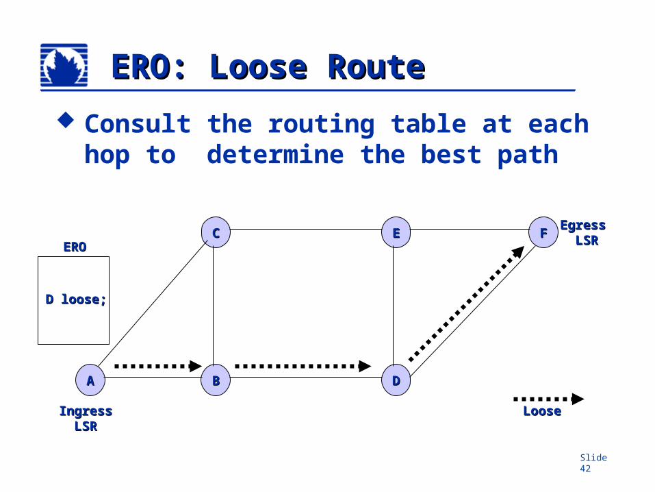
ERO: Loose RouteERO: Loose Route
AA
FFEE
DD
CC
BB
Egress Egress LSRLSR
Consult the routing table at each hop to determine the best path
IngressIngressLSRLSR
D loose;D loose;
EROERO
LooseLoose

Slide 43
ERO: Strict/Loose PathERO: Strict/Loose Path
AA
FFEE
DD
CC
BB
Egress Egress LSRLSR
Strict and loose routes can be mixed
IngressIngressLSRLSR
C strict;C strict;D loose;D loose;F strict;F strict;
EROERO
StrictStrict
LooseLoose
Slide 44
Router B Router C
Router E
Router D
.2
.1
.2.1
10.0
.31/
30
Router GRouter F
192.168.16.1
192.168.0.1 192.168.2.1
192.168.5.1
192.168.8.1 192.168.12.1
192.168.24.1
Router A.1
.210.0.13/30
10.0.0/30
10.0.24/30.1
.2
10.0.1/30.1.2
10.0.8/30
.1
.210
.0.2
/30
.1
.2
10.0.16/30.2
.1
10.0.15/30
.2
.1
Router X
SmallNet
Router Y
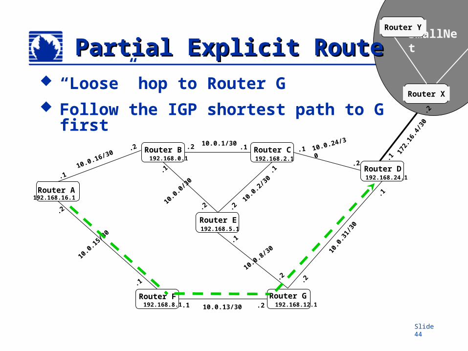
Partial Explicit RoutePartial Explicit Route
172.
16.4
/30
.2
.1
“Loose” hop to Router G Follow the IGP shortest path to G first
Slide 45
Router B Router C
Router E
Router D
.2
.1
10.0
.31/
30
Router GRouter F
192.168.16.1
192.168.0.1 192.168.2.1
192.168.5.1
192.168.8.1 192.168.12.1
192.168.24.1
Router A.1
.2
10.0.0/30
10.0.24/30.1
.2
10.0.1/30.1.2
10.0.8/30
.1
.210
.0.2
/30
.1
.2
10.0.16/30.2
.1
10.0.15/30
.2
.1
Router X
SmallNet
Router Y
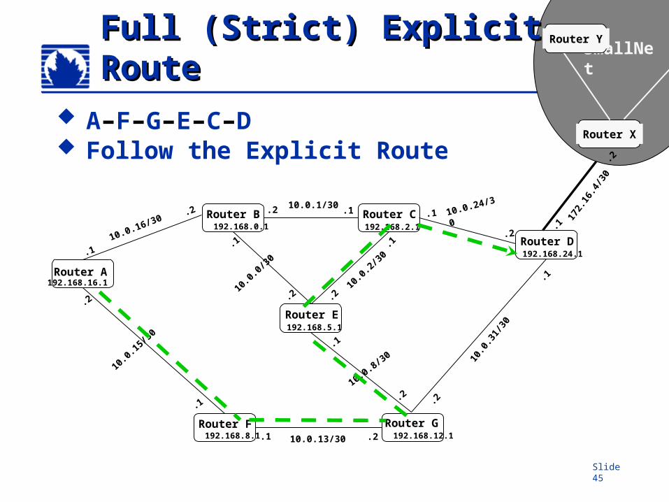
Full (Strict) Explicit RouteFull (Strict) Explicit Route
172.
16.4
/30
.2
.1
A–F–G–E–C–D Follow the Explicit Route
.2.1 10.0.13/30
Slide 46
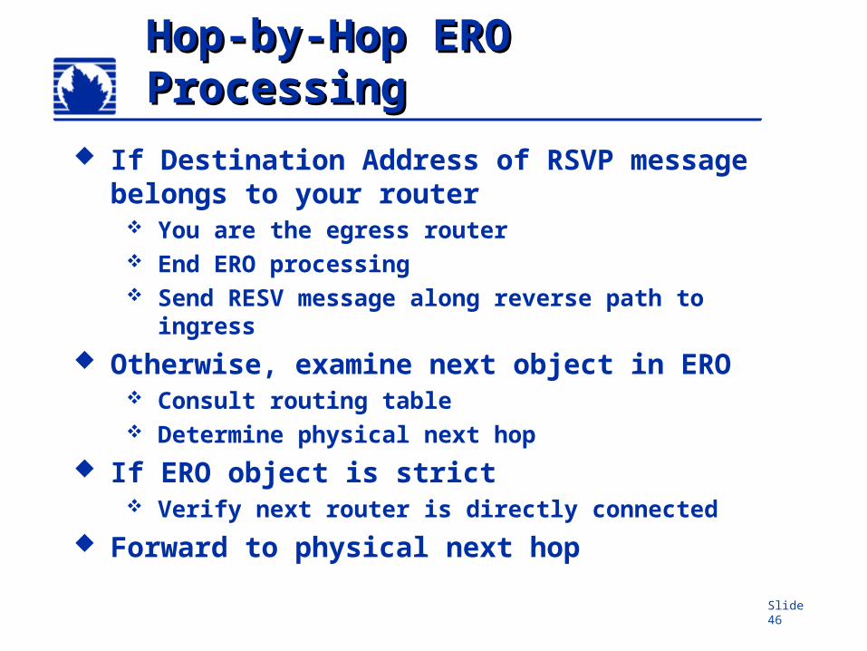
Hop-by-Hop ERO Hop-by-Hop ERO ProcessingProcessing
If Destination Address of RSVP message belongs to your router
You are the egress router End ERO processing Send RESV message along reverse path to
ingress Otherwise, examine next object in ERO
Consult routing table Determine physical next hop
If ERO object is strict Verify next router is directly connected
Forward to physical next hop
Slide 47
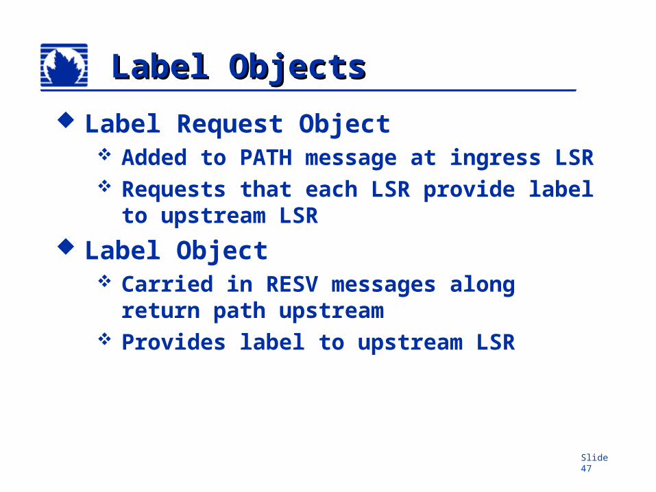
Label ObjectsLabel Objects
Label Request Object Added to PATH message at ingress
LSR Requests that each LSR provide label
to upstream LSR Label Object
Carried in RESV messages along return path upstream
Provides label to upstream LSR
Slide 48
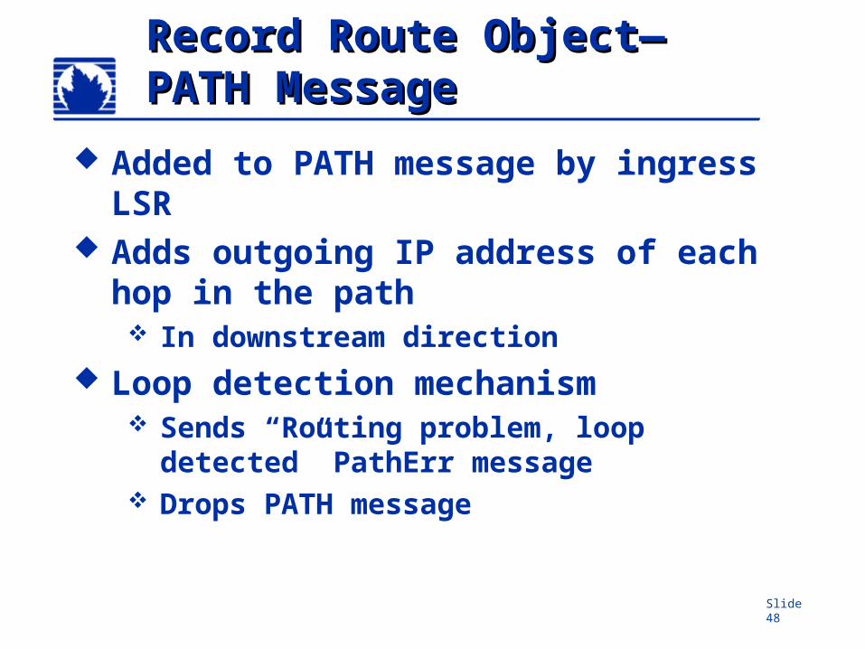
Record Route ObjectRecord Route Object——PATH MessagePATH Message
Added to PATH message by ingress LSR
Adds outgoing IP address of each hop in the path In downstream direction
Loop detection mechanism Sends “Routing problem, loop
detected” PathErr message Drops PATH message
Slide 49
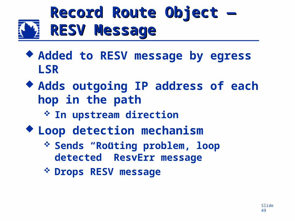
Record Route Object Record Route Object ——RESV MessageRESV Message
Added to RESV message by egress LSR
Adds outgoing IP address of each hop in the path In upstream direction
Loop detection mechanism Sends “Routing problem, loop
detected” ResvErr message Drops RESV message
Slide 50
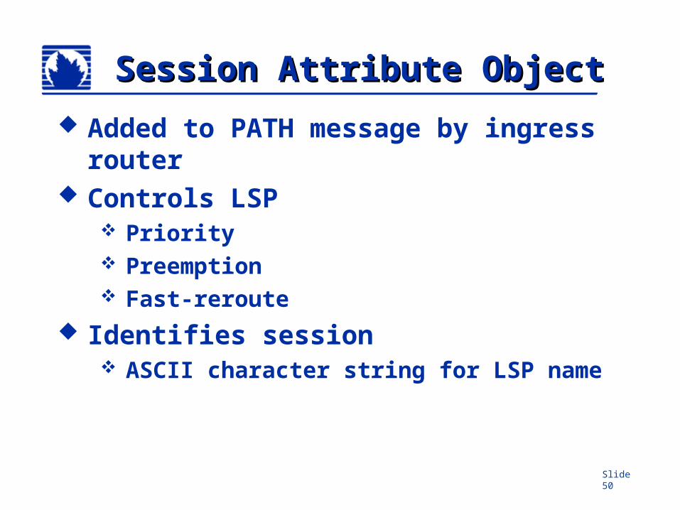
Session Attribute ObjectSession Attribute Object
Added to PATH message by ingress router
Controls LSP Priority Preemption Fast-reroute
Identifies session ASCII character string for LSP name
Slide 51
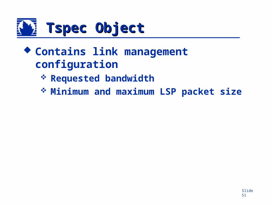
Tspec ObjectTspec Object
Contains link management configuration Requested bandwidth Minimum and maximum LSP packet
size
Slide 52
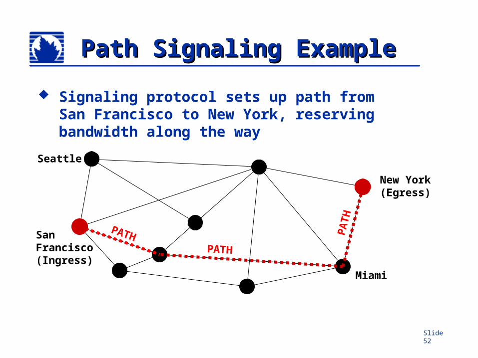
Path Signaling ExamplePath Signaling Example
Signaling protocol sets up path from San Francisco to New York, reserving bandwidth along the way
PATH
Miami
Seattle
PATH
PA
TH
SanFrancisco(Ingress)
New York(Egress)
Slide 53
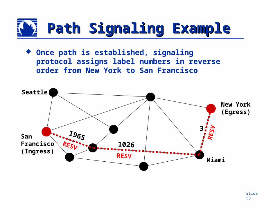
Path Signaling ExamplePath Signaling Example
Once path is established, signaling protocol assigns label numbers in reverse order from New York to San Francisco
SanFrancisco(Ingress)
New York(Egress)
19651026
3
Miami
Seattle
RESV
RESV
RESV
Slide 54
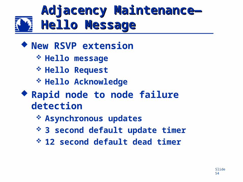
Adjacency MaintenanceAdjacency Maintenance——Hello MessageHello Message
New RSVP extension Hello message Hello Request Hello Acknowledge
Rapid node to node failure detection Asynchronous updates 3 second default update timer 12 second default dead timer
Slide 55
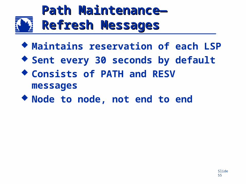
Path MaintenancePath Maintenance——Refresh MessagesRefresh Messages
Maintains reservation of each LSP Sent every 30 seconds by default Consists of PATH and RESV
messages Node to node, not end to end
Slide 56
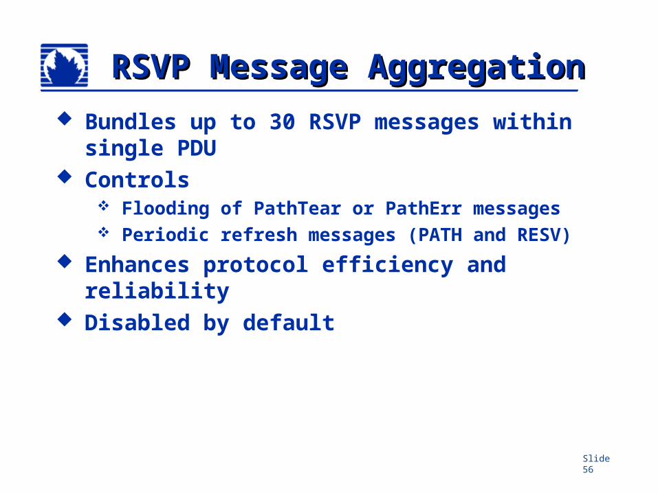
RSVP Message RSVP Message AggregationAggregation
Bundles up to 30 RSVP messages within single PDU
Controls Flooding of PathTear or PathErr messages Periodic refresh messages (PATH and RESV)
Enhances protocol efficiency and reliability
Disabled by default
Slide 57
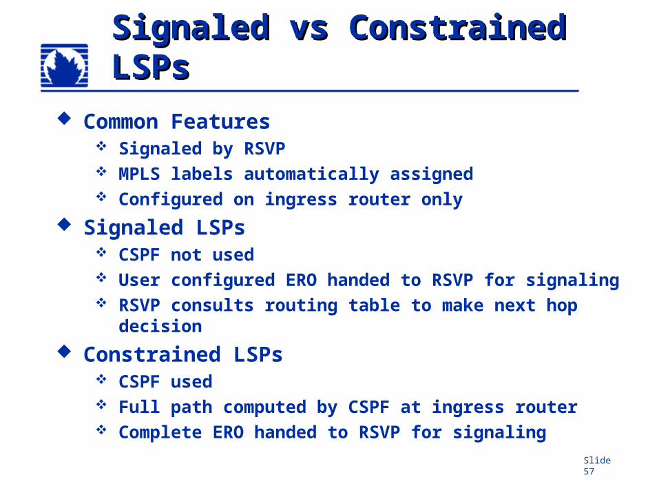
Signaled vs Constrained Signaled vs Constrained LSPsLSPs
Common Features Signaled by RSVP MPLS labels automatically assigned Configured on ingress router only
Signaled LSPs CSPF not used User configured ERO handed to RSVP for signaling RSVP consults routing table to make next hop
decision Constrained LSPs
CSPF used Full path computed by CSPF at ingress router Complete ERO handed to RSVP for signaling
Slide 58
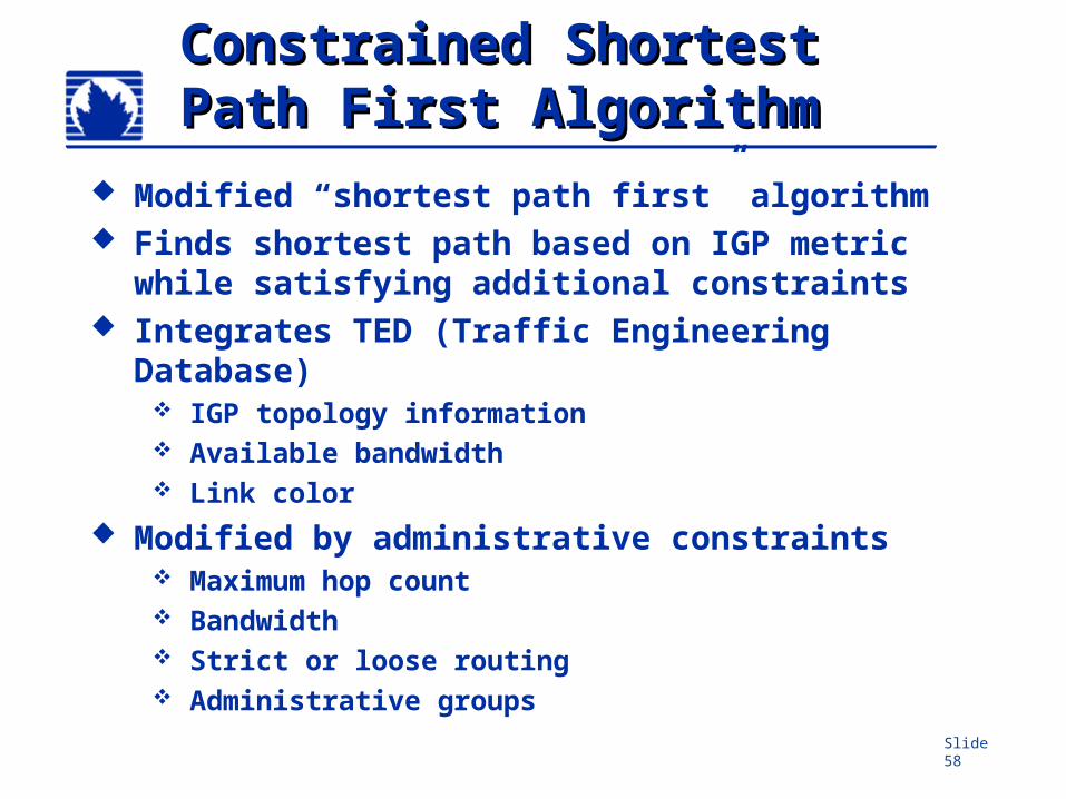
Constrained ShortestConstrained ShortestPath First AlgorithmPath First Algorithm
Modified “shortest path first” algorithm Finds shortest path based on IGP metric
while satisfying additional constraints Integrates TED (Traffic Engineering
Database) IGP topology information Available bandwidth Link color
Modified by administrative constraints Maximum hop count Bandwidth Strict or loose routing Administrative groups
Slide 59
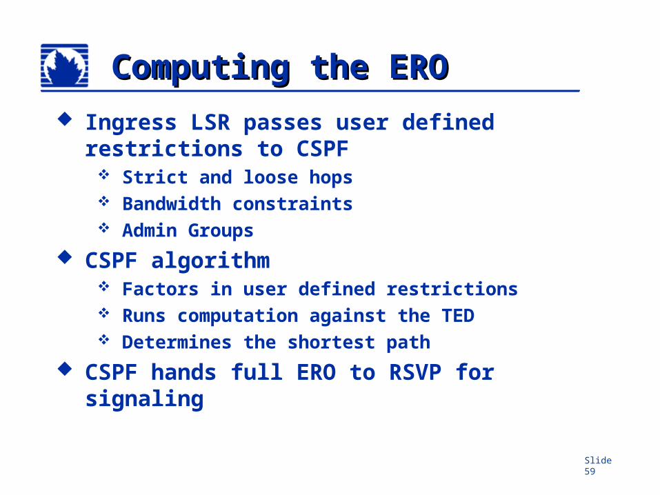
Computing the EROComputing the ERO Ingress LSR passes user defined
restrictions to CSPF Strict and loose hops Bandwidth constraints Admin Groups
CSPF algorithm Factors in user defined restrictions Runs computation against the TED Determines the shortest path
CSPF hands full ERO to RSVP for signaling
Slide 60
Traffic Engineering Traffic Engineering DatabaseDatabase
Slide 61
Traffic Engineering Traffic Engineering DatabaseDatabase
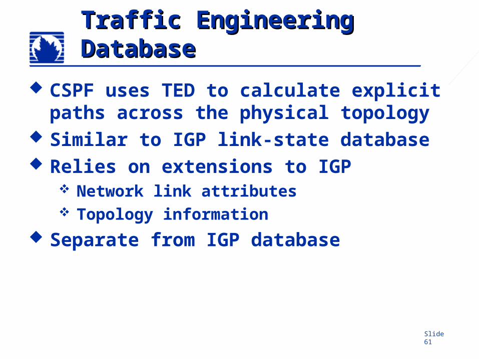
CSPF uses TED to calculate explicit paths across the physical topology
Similar to IGP link-state database Relies on extensions to IGP
Network link attributes Topology information
Separate from IGP database
Slide 62
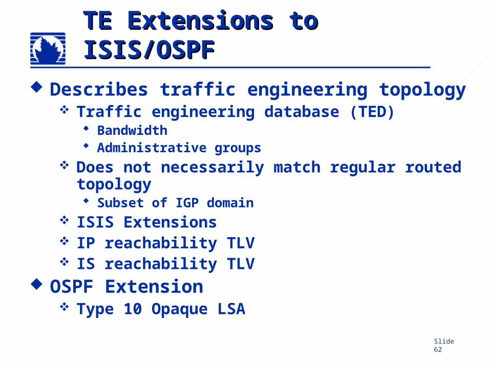
TE Extensions to TE Extensions to ISIS/OSPFISIS/OSPF
Describes traffic engineering topology Traffic engineering database (TED)
Bandwidth Administrative groups
Does not necessarily match regular routed topology Subset of IGP domain
ISIS Extensions IP reachability TLV IS reachability TLV
OSPF Extension Type 10 Opaque LSA
Slide 63
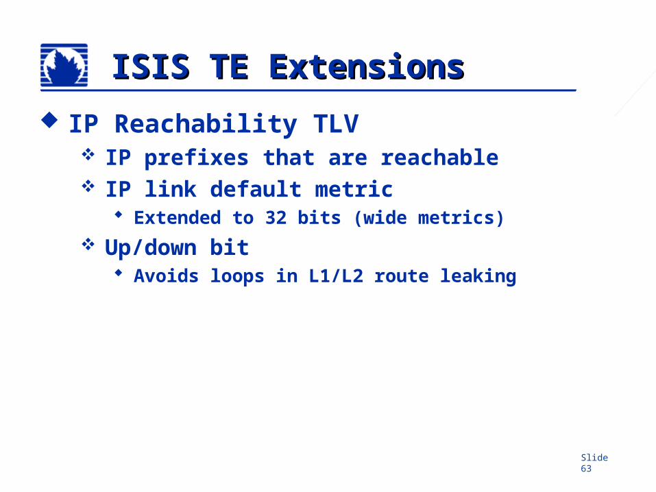
ISIS TE ExtensionsISIS TE Extensions
IP Reachability TLV IP prefixes that are reachable IP link default metric
Extended to 32 bits (wide metrics) Up/down bit
Avoids loops in L1/L2 route leaking
Slide 64
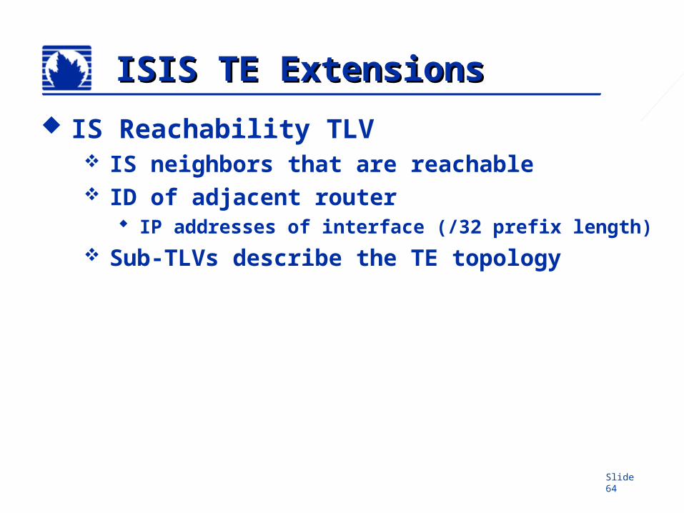
ISIS TE ExtensionsISIS TE Extensions
IS Reachability TLV IS neighbors that are reachable ID of adjacent router
IP addresses of interface (/32 prefix length) Sub-TLVs describe the TE topology
Slide 65
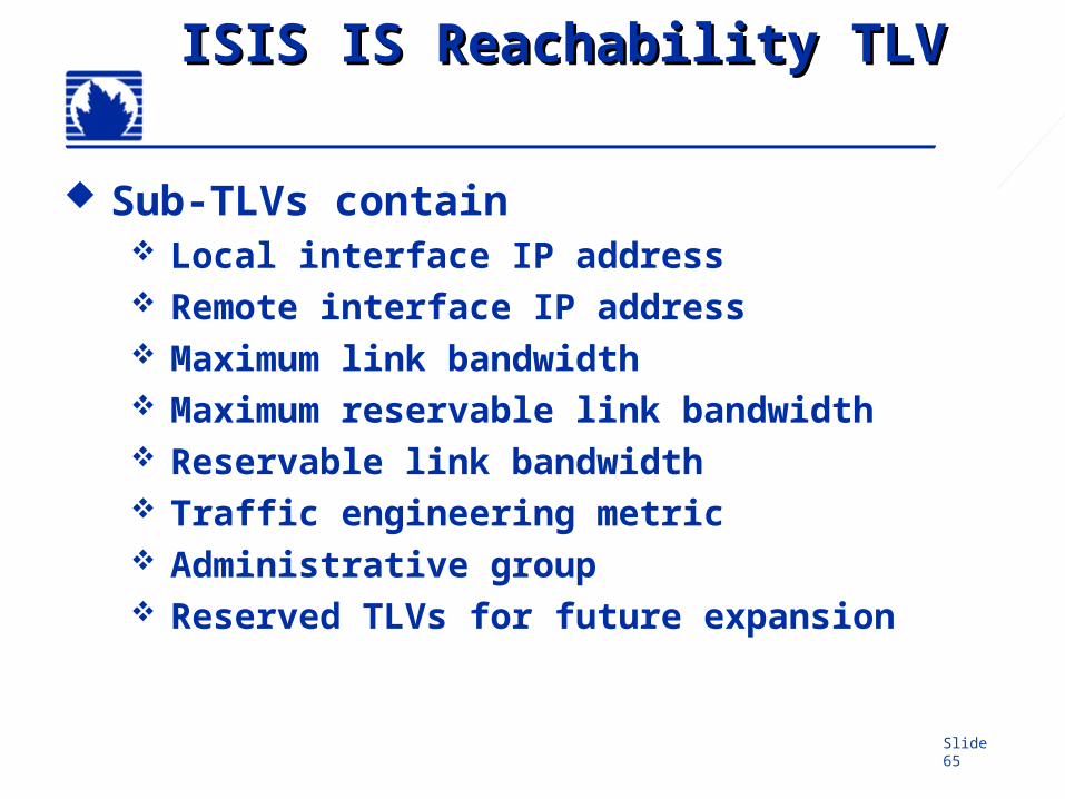
ISIS IS Reachability TLVISIS IS Reachability TLV
Sub-TLVs contain Local interface IP address Remote interface IP address Maximum link bandwidth Maximum reservable link bandwidth Reservable link bandwidth Traffic engineering metric Administrative group Reserved TLVs for future expansion
Slide 66
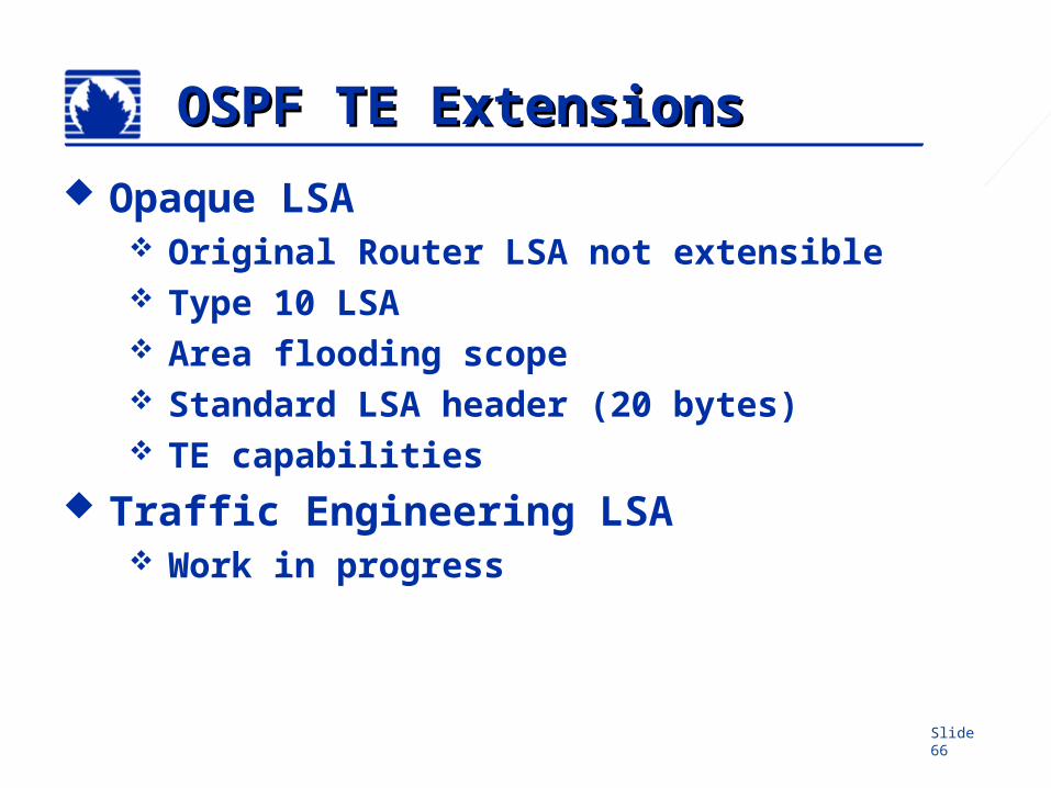
OSPF TE ExtensionsOSPF TE Extensions
Opaque LSA Original Router LSA not extensible Type 10 LSA Area flooding scope Standard LSA header (20 bytes) TE capabilities
Traffic Engineering LSA Work in progress
Slide 67
Router B Router C
Router E
Router D
.2
.1
.2.1
10.0
.31/
30
Router GRouter F
192.168.16.1
192.168.0.1 192.168.2.1
192.168.5.1
192.168.8.1 192.168.12.1
192.168.24.1
Router A.1
.210.0.13/30
10.0.0/30
10.0.24/30.1
.2
10.0.1/30.1.2
10.0.8/30
.1
.210
.0.2
/30
.1
.2
10.0.16/30.2
.1
10.0.15/30
.2
.1
Router X
SmallNet
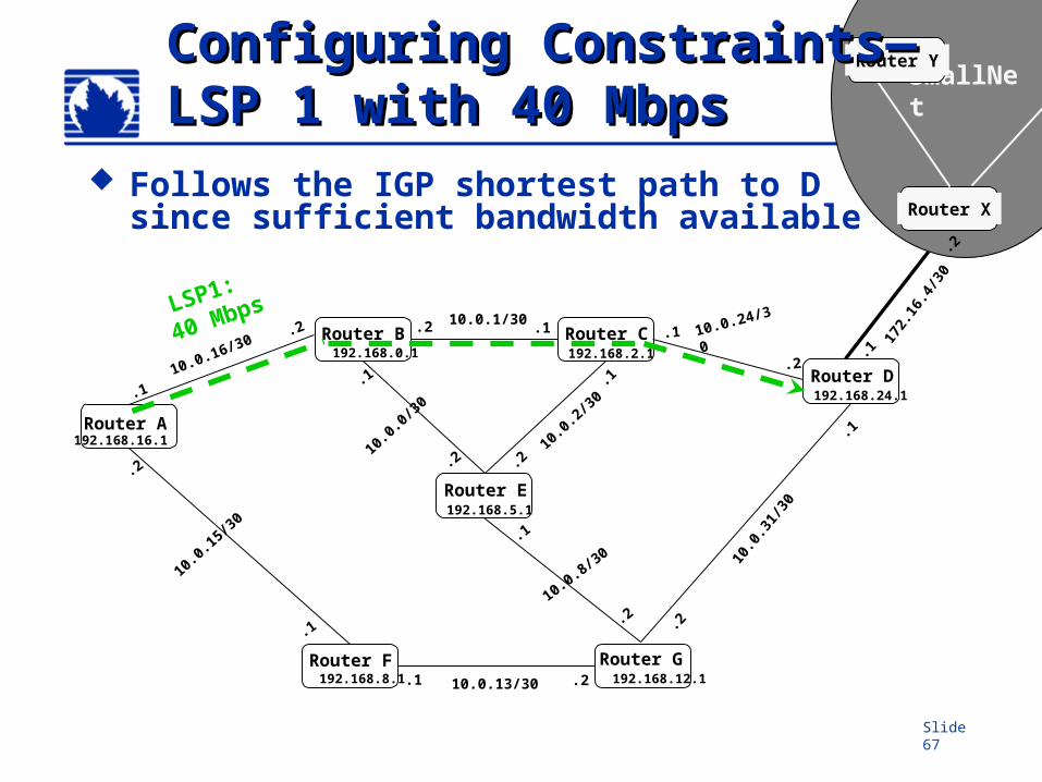
Router YConfiguring Constraints—Configuring Constraints—LSP 1 with 40 MbpsLSP 1 with 40 Mbps
172.
16.4
/30
.2
.1
Follows the IGP shortest path to D since sufficient bandwidth available
LSP1:
40 Mbps
Slide 68
Router B Router C
Router E
Router D
.2
.1
.2.1
10.0
.31/
30
Router GRouter F
192.168.16.1
192.168.0.1 192.168.2.1
192.168.5.1
192.168.8.1 192.168.12.1
192.168.24.1
Router A.1
.210.0.13/30
10.0.0/30
10.0.24/30.1
.2
10.0.1/30.1.2
10.0.8/30
.1
.210
.0.2
/30
.1
.2
10.0.16/30.2
.1
10.0.15/30
.2
.1
Router X
SmallNet
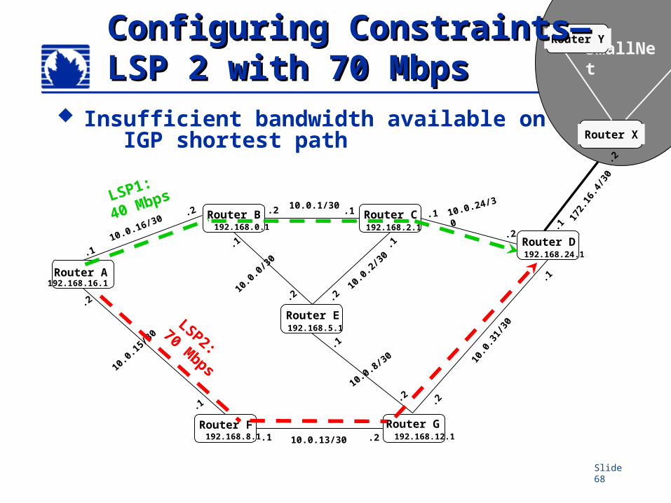
Router YConfiguring Constraints—Configuring Constraints—LSP 2 with 70 MbpsLSP 2 with 70 Mbps
172.
16.4
/30
.2
.1
Insufficient bandwidth available on IGP shortest path
LSP2:
70 Mbps
LSP1:
40 Mbps
Slide 69
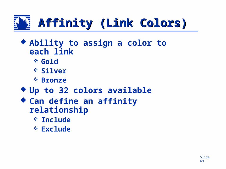
Affinity (Link Colors)Affinity (Link Colors)
Ability to assign a color to each link Gold Silver Bronze
Up to 32 colors available Can define an affinity
relationship Include Exclude
Slide 70
Router B Router C
Router E
Router D
.2
.1
.2.1
10.0
.31/
30
Router GRouter F
192.168.16.1
192.168.0.1 192.168.2.1
192.168.5.1
192.168.8.1 192.168.12.1
192.168.24.1
Router A.1
.210.0.13/30
10.0.0/30
10.0.24/30.1
.2
10.0.1/30.1.2
10.0.8/30
.1
.210
.0.2
/30
.1
.2
10.0.16/30.2
.1
10.0.15/30
.2
.1
Router X
SmallNet
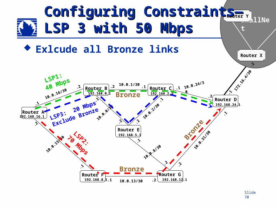
Router YConfiguring Constraints—Configuring Constraints—LSP 3 with 50 MbpsLSP 3 with 50 Mbps
172.
16.4
/30
.2
.1
Exlcude all Bronze links
LSP1:
40 Mbps
LSP2:
70 Mbps
Bronze
Bronz
e
Bronze
LSP3: 20 Mbps
Exclude Bronze
Slide 71
PreemptionPreemption Defines relative importance of LSPs on
same ingress router CSPF uses priority to optimize paths Higher priority LSPs
Are established first Offer more optimal path selection May tear down lower priority LSPs when
rerouting Default configuration makes all LSPs
equal
Slide 72
PreemptionPreemption Controlled by two settings
Setup priority and hold (reservation) priority New LSP compares its setup priority with hold
priority of existing LSP If setup priority is less than hold priority,
existing LSP is rerouted to make room Priorities from 0 (strong) through 7 (weak) Defaults
Setup priority is 7 (do not preempt) Reservation priority is 0 (do not allow
preemption)
Use with caution No large scale experience with this feature
Slide 73
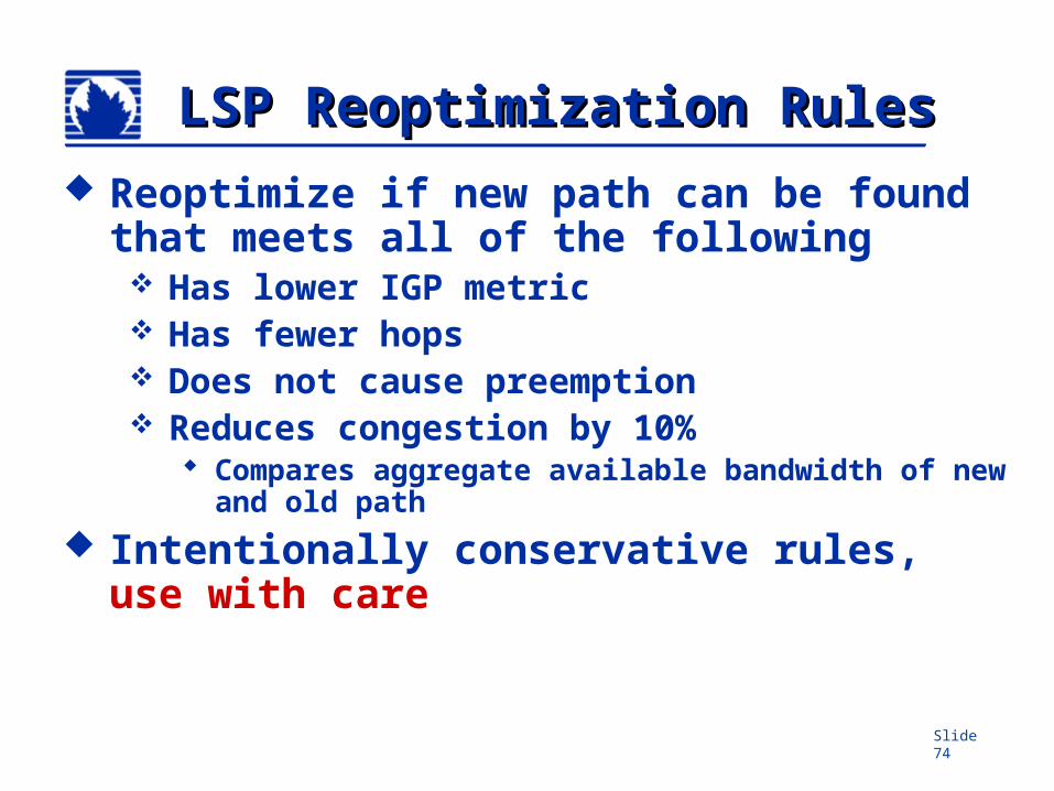
LSP ReoptimizationLSP Reoptimization
Reroutes LSPs that would benefit from improvements in the network Special rules apply
Disabled by default in JUNOS
Slide 74
LSP Reoptimization RulesLSP Reoptimization Rules Reoptimize if new path can be found
that meets all of the following Has lower IGP metric Has fewer hops Does not cause preemption Reduces congestion by 10%
Compares aggregate available bandwidth of new and old path
Intentionally conservative rules, use with care
Slide 75
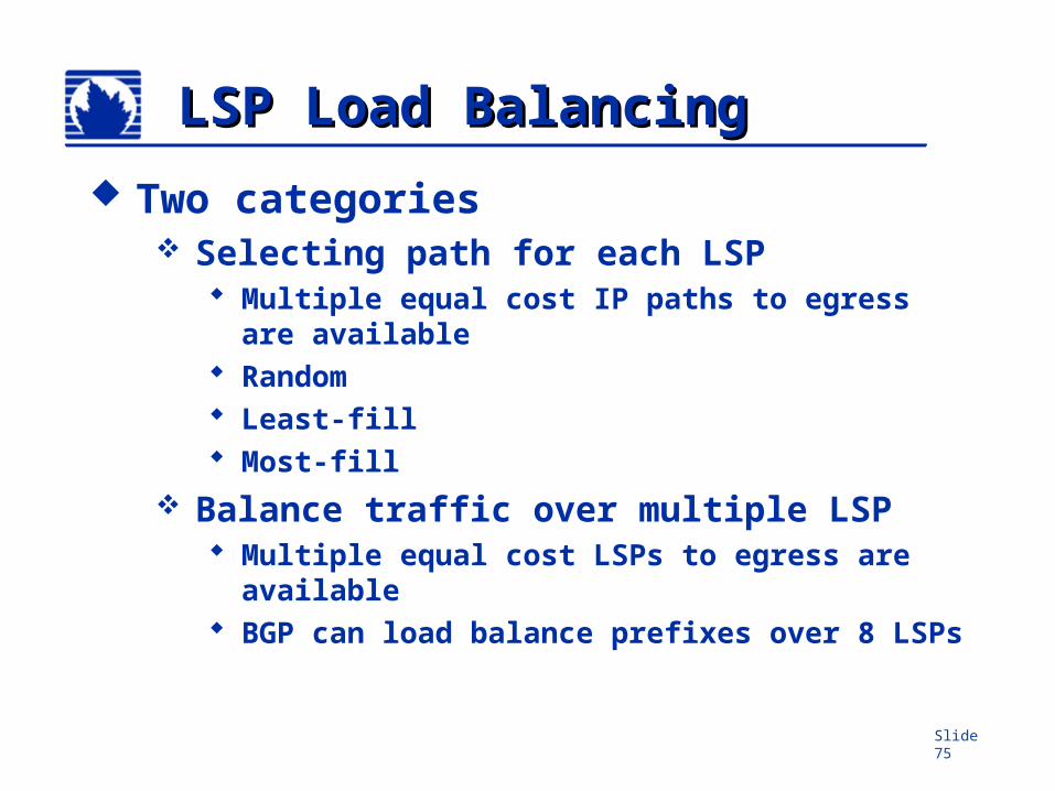
LSP Load BalancingLSP Load Balancing
Two categories Selecting path for each LSP
Multiple equal cost IP paths to egress are available
Random Least-fill Most-fill
Balance traffic over multiple LSP Multiple equal cost LSPs to egress are
available BGP can load balance prefixes over 8 LSPs
Slide 76
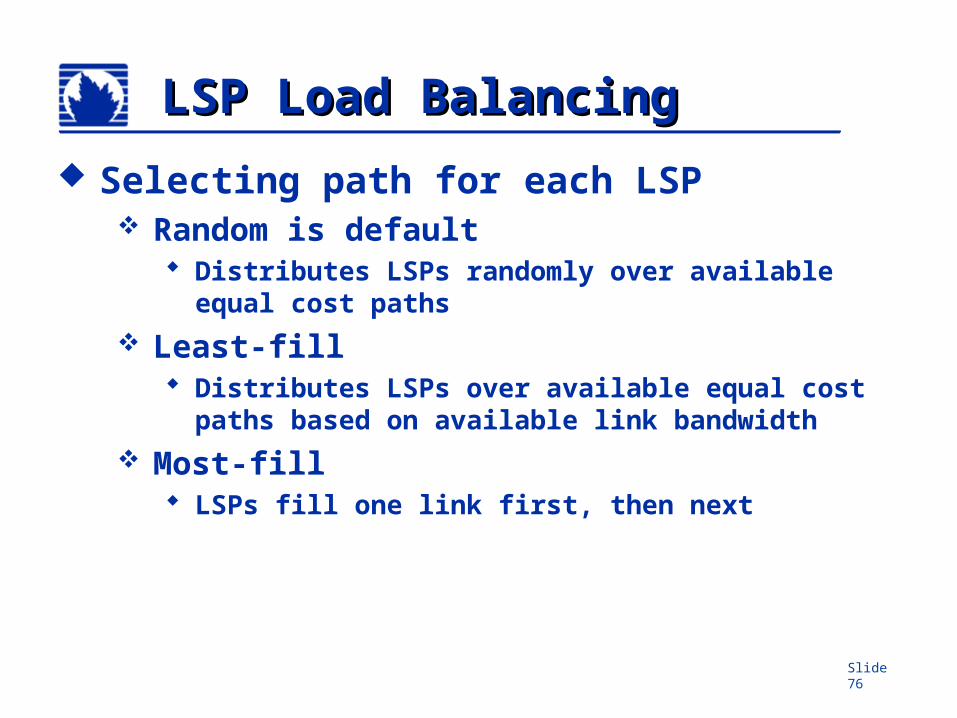
LSP Load BalancingLSP Load Balancing
Selecting path for each LSP Random is default
Distributes LSPs randomly over available equal cost paths
Least-fill Distributes LSPs over available equal cost paths
based on available link bandwidth Most-fill
LSPs fill one link first, then next
Slide 77
Router B Router C
Router E
Router D
.2
.1
.2.1
10.0
.31/
30
Router GRouter F
192.168.16.1
192.168.0.1 192.168.2.1
192.168.5.1
192.168.8.1 192.168.12.1
192.168.24.1
Router A.1
.210.0.13/30
10.0.0/30
10.0.24/30.1
.2
10.0.1/30.1.2
10.0.8/30
.1
.210
.0.2
/30
.1
.2
10.0.16/30.2
.1
10.0.15/30
.2
.1
Router X
SmallNet
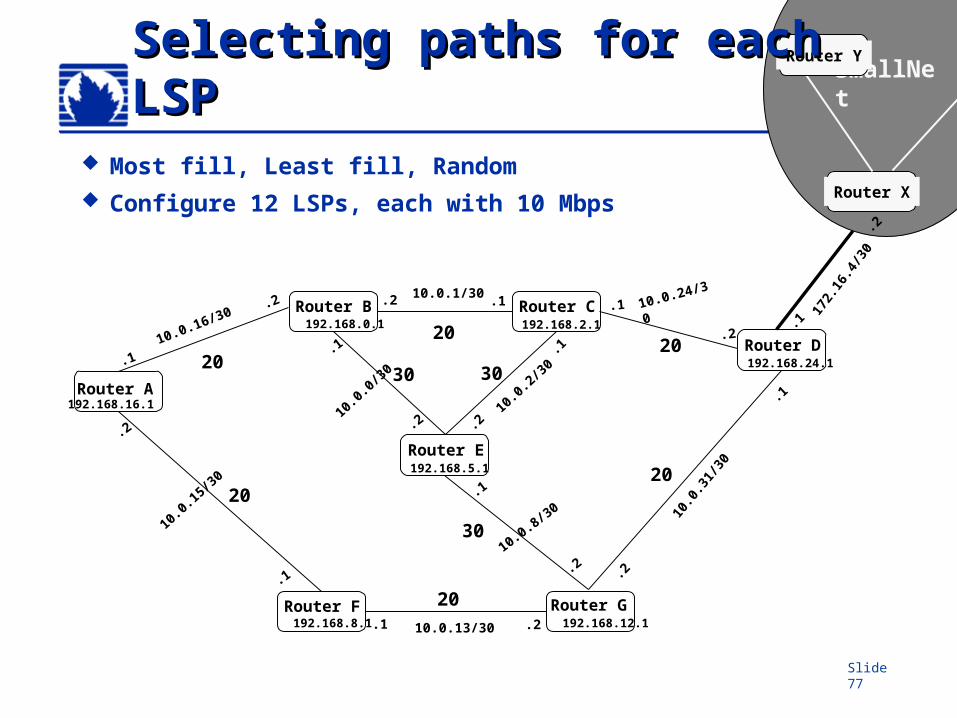
Router YSelecting paths for eachSelecting paths for eachLSPLSP
172.
16.4
/30
.2
.1
Most fill, Least fill, Random Configure 12 LSPs, each with 10 Mbps
20
2020
20
20
20
3030
30
Slide 78
Load BalancingLoad Balancing
Balancing traffic over multiple LSPs Up to 16 equal cost paths for BGP JUNOS default is per-prefix Per-packet (per-flow) knob available
Slide 79
Router B Router C
Router E
Router D
.2
.1
.2.1
10.0
.31/
30
Router GRouter F
192.168.16.1
192.168.0.1 192.168.2.1
192.168.5.1
192.168.8.1 192.168.12.1
192.168.24.1
Router A.1
.210.0.13/30
10.0.0/30
10.0.24/30.1
.2
10.0.1/30.1.2
10.0.8/30
.1
.210
.0.2
/30
.1
.2
10.0.16/30.2
.1
10.0.15/30
.2
.1
Router X
SmallNet
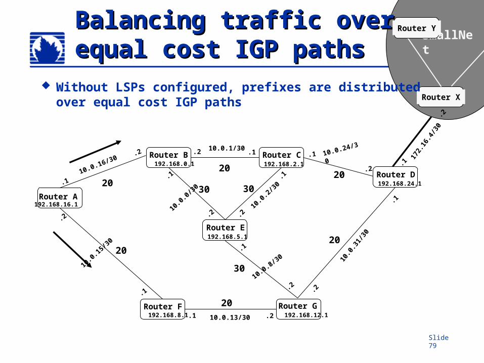
Router YBalancing traffic over Balancing traffic over equal cost IGP pathsequal cost IGP paths
172.
16.4
/30
.2
.1
Without LSPs configured, prefixes are distributed over equal cost IGP paths
20
2020
20
20
20
3030
30
Slide 80
Router B Router C
Router E
Router D
.2
.1
.2.1
10.0
.31/
30
Router GRouter F
192.168.16.1
192.168.0.1 192.168.2.1
192.168.5.1
192.168.8.1 192.168.12.1
192.168.24.1
Router A.1
.210.0.13/30
10.0.0/30
10.0.24/30.1
.2
10.0.1/30.1.2
10.0.8/30
.1
.210
.0.2
/30
.1
.2
10.0.16/30.2
.1
10.0.15/30
.2
.1
Router X
SmallNet
Router YBalancing traffic over Balancing traffic over equal cost LSPsequal cost LSPs
172.
16.4
/30
.2
.1
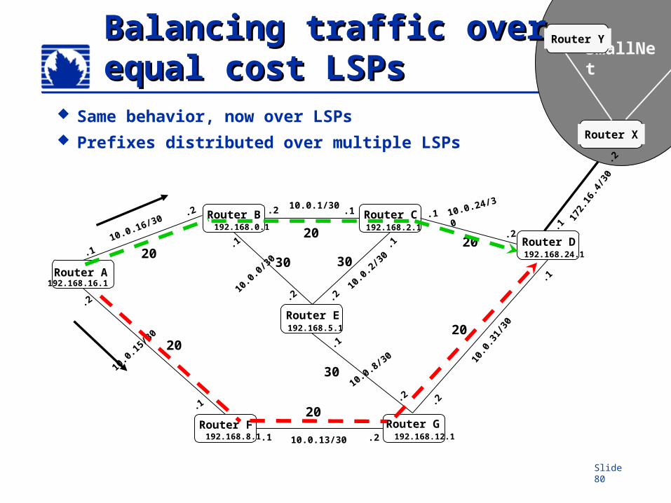
Same behavior, now over LSPs Prefixes distributed over multiple LSPs
20
2020
20
20
20
3030
30
Slide 81
Traffic ProtectionTraffic Protection
Primary LSP Retry timer Retry limit
Secondary LSPs Standby option
Fast Reroute Adaptive mode
Slide 82
Primary LSPPrimary LSP
Optional If configured, becomes preferred path
for LSP If no primary configured
LSR makes all decisions to reach egress Zero or one primary path Revertive capability
Revertive behavior can be modified
Slide 83
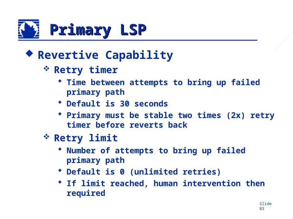
Primary LSPPrimary LSP
Revertive Capability Retry timer
Time between attempts to bring up failed primary path
Default is 30 seconds Primary must be stable two times (2x) retry
timer before reverts back Retry limit
Number of attempts to bring up failed primary path
Default is 0 (unlimited retries) If limit reached, human intervention then
required
Slide 84
Secondary LSPSecondary LSP
Optional Zero or more secondary paths All secondary paths are equal
Selection based on listed order of configuration
Standby knob Maintains secondary path in ‘up’ condition Eliminates call-setup delay of secondary
LSP Additional state information must be
maintained
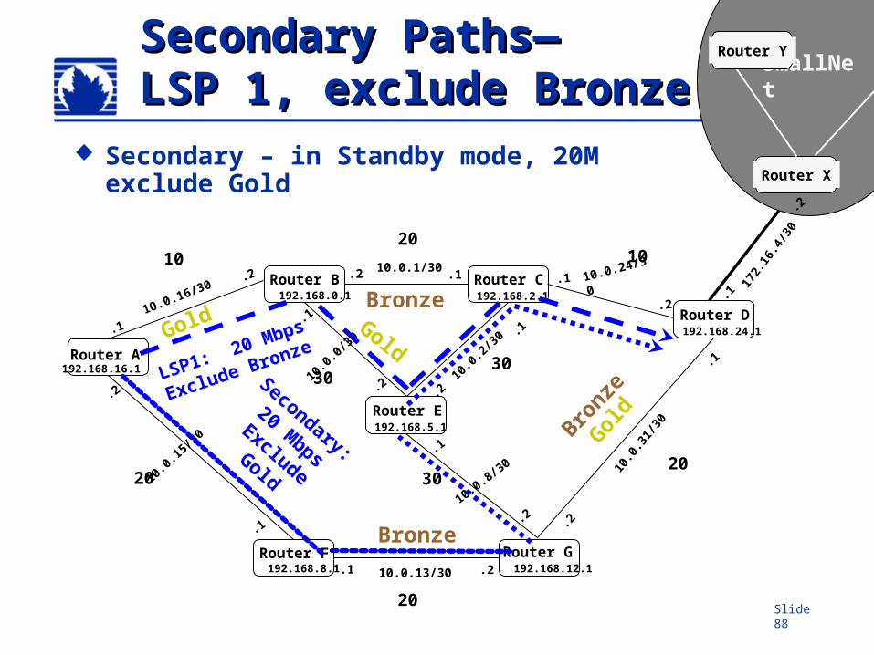
Slide 85
Router B Router C
Router E
Router D
.2
.1
.2.1
10.0
.31/
30
Router GRouter F
192.168.16.1
192.168.0.1 192.168.2.1
192.168.5.1
192.168.8.1 192.168.12.1
192.168.24.1
Router A.1
.210.0.13/30
10.0.0/30
10.0.24/30.1
.2
10.0.1/30.1.2
10.0.8/30
.1
.210
.0.2
/30
.1
.2
10.0.16/30.2
.1
10.0.15/30
.2
.1
Router X
SmallNet
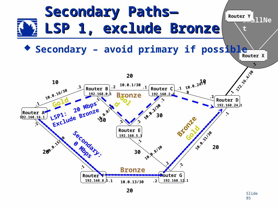
Router YSecondary Paths—Secondary Paths—LSP 1, exclude BronzeLSP 1, exclude Bronze
172.
16.4
/30
.2
.1
Secondary – avoid primary if possible
Secondary:
0 Mbps
Bronze
Gol
d
Bronze
10.0
.2/3
0
LSP1: 20 Mbps
Exclude Bronze
2010 10
20
20
20
3030
30
Gold
Bronz
e
Gold
Slide 86
Adaptive Mode Adaptive Mode
Applies to LSP rerouting Primary & secondary sharing links
Avoids double counting SE Reservation style
Slide 87
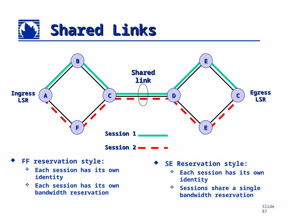
Shared LinksShared Links
SharedSharedlinklink
Session 1Session 1
Session 2Session 2
FF reservation style: Each session has its own
identity Each session has its own
bandwidth reservation
SE Reservation style: Each session has its own
identity Sessions share a single
bandwidth reservation
AA
FF
CC
BB
DD
EE
CC
EE
IngressIngressLSRLSR
EgressEgressLSRLSR
Slide 88
Router B Router C
Router E
Router D
.2
.1
.2.1
10.0
.31/
30
Router GRouter F
192.168.16.1
192.168.0.1 192.168.2.1
192.168.5.1
192.168.8.1 192.168.12.1
192.168.24.1
Router A.1
.210.0.13/30
10.0.0/30
10.0.24/30.1
.2
10.0.1/30.1.2
10.0.8/30
.1
.2 10.0
.2/3
0 .1
.2
10.0.16/30.2
.1
10.0.15/30
.2
.1
Router X
SmallNet
Router YSecondary Paths—Secondary Paths—LSP 1, exclude BronzeLSP 1, exclude Bronze
172.
16.4
/30
.2
.1
Secondary – in Standby mode, 20M exclude Gold
Secondary:
20 Mbps
Exclude Gold
Bronze
Gol
d
Bronze
LSP1: 20 Mbps
Exclude Bronze
2010 10
20
20
20
3030
30
GoldGold
Bronze
Slide 89
Fast RerouteFast Reroute
Configured on ingress router only Detours around node or link failure
~100s of ms reroute time Detour paths immediately available Crank-back to node, not ingress
router Uses TED to calculate detour
Slide 90
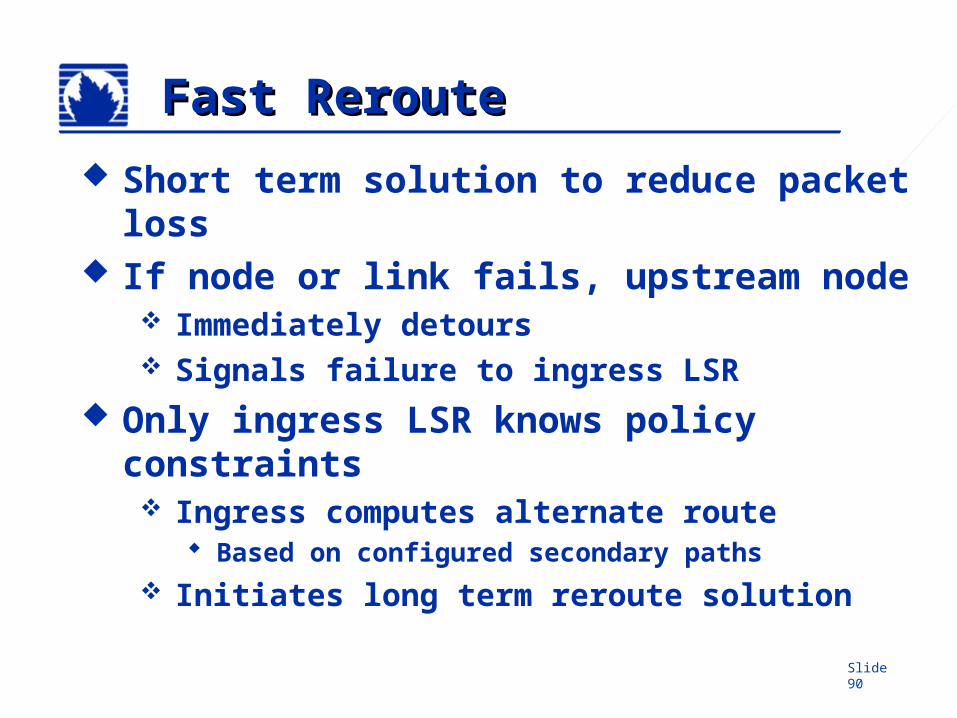
Fast RerouteFast Reroute
Short term solution to reduce packet loss
If node or link fails, upstream node Immediately detours Signals failure to ingress LSR
Only ingress LSR knows policy constraints Ingress computes alternate route
Based on configured secondary paths Initiates long term reroute solution
Slide 91
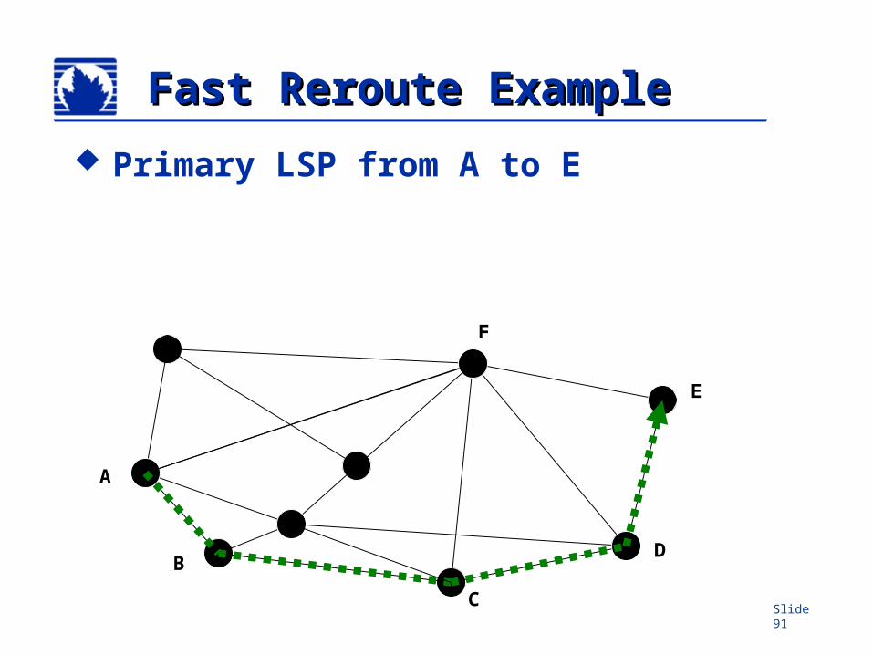
Fast Reroute ExampleFast Reroute Example
Primary LSP from A to E
A
C
BD
E
F
Slide 92
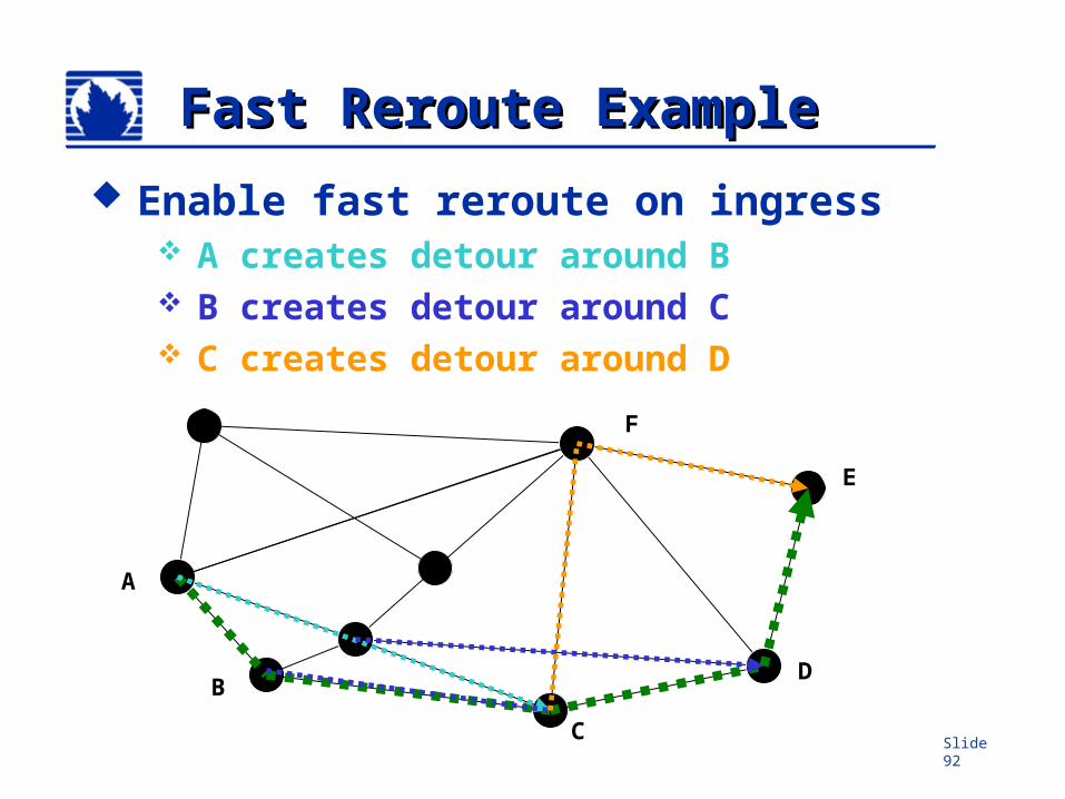
Fast Reroute ExampleFast Reroute Example
Enable fast reroute on ingress A creates detour around B B creates detour around C C creates detour around D
A
D
C
B
E
F
Slide 93
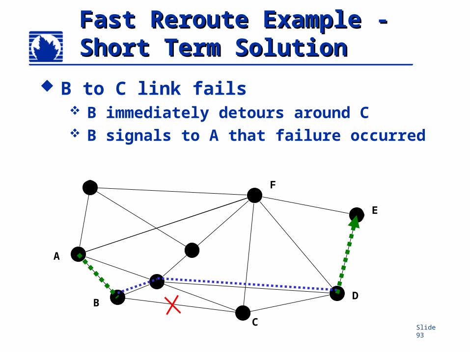
Fast Reroute Example - Fast Reroute Example - Short Term SolutionShort Term Solution
B to C link fails B immediately detours around C B signals to A that failure occurred
A
D
C
B
E
F
Slide 94
Fast Reroute Example – Fast Reroute Example – Long Term SolutionLong Term Solution
A calculates and signals new primary path
A
D
C
B
E
F
Slide 95
LSP ReroutingLSP Rerouting
Initiated by ingress LSR Exception is fast reroute
Conditions that trigger reroute More optimal route becomes available Failure of a resource along the LSP path Preemption occurs Manual configuration change
Make before break (if adaptive) Establish new LSP with SE style Transfer traffic to new LSP Tear down old LSP
Slide 96
Mapping Transit TrafficMapping Transit Traffic
Mapping transit destinations JUNOS default mode Only BGP prefixes are bound to LSPs Only BGP can use LSPs for its
recursive route calculations Only BGP prefixes that have the LSP
destination address as the BGP next-hop are resolvable through the LSP
Slide 97
Router B Router C
Router E
Router D
.2
.1
10.0
.31/
30
Router GRouter F
192.168.16.1
192.168.0.1 192.168.2.1
192.168.5.1
192.168.8.1 192.168.12.1
192.168.24.1
Router A.1
.2
10.0.0/30
10.0.24/30.1
.2
10.0.1/30.1.2
10.0.8/30
.1
.210
.0.2
/30
.1
.2
10.0.16/30.2
.1
10.0.15/30
.2
.1
Router X
SmallNet
Router YRoute Resolution– Route Resolution– Transit Traffic ExampleTransit Traffic Example
172.
16.4
/30
.2
.1
.2.1 10.0.13/30
134.
112/
16
E-BGP
134.112/16
I-BGP
Configure a “next hop
self” policy on Router D
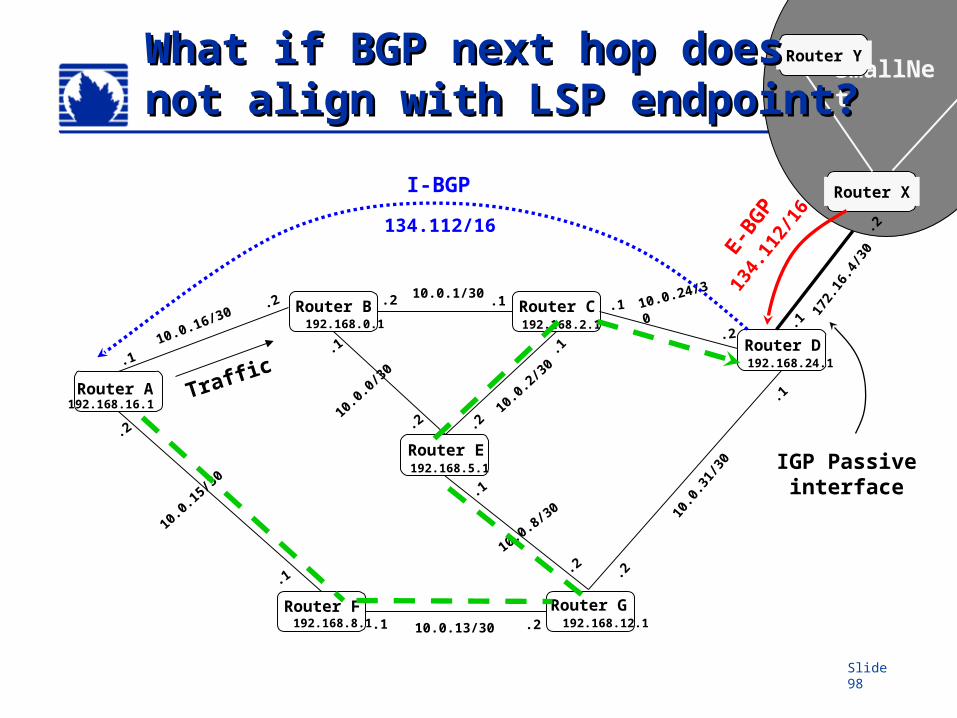
Slide 98
Router B Router C
Router E
Router D
.2
.1
10.0
.31/
30
Router GRouter F
192.168.16.1
192.168.0.1 192.168.2.1
192.168.5.1
192.168.8.1 192.168.12.1
192.168.24.1
Router A.1
.2
10.0.0/30
10.0.24/30.1
.2
10.0.1/30.1.2
10.0.8/30
.1
.210
.0.2
/30
.1
.2
10.0.16/30.2
.1
10.0.15/30
.2
.1
Router X
SmallNet
Router YWhat if BGP next hop doesWhat if BGP next hop doesnot align with LSP endpoint?not align with LSP endpoint?
172.
16.4
/30
.2
.1
.2.1 10.0.13/30
134.
112/
16
E-BGP
134.112/16
I-BGP
IGP Passive interface
Traffic
Slide 99
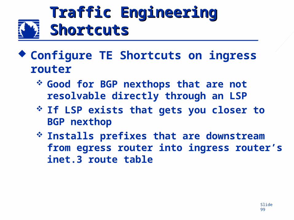
Traffic Engineering Traffic Engineering ShortcutsShortcuts
Configure TE Shortcuts on ingress router Good for BGP nexthops that are not
resolvable directly through an LSP If LSP exists that gets you closer to BGP
nexthop Installs prefixes that are downstream
from egress router into ingress router’s inet.3 route table
Slide 100
Router B Router C
Router E
Router D
.2
.1
10.0
.31/
30
Router GRouter F
192.168.16.1
192.168.0.1 192.168.2.1
192.168.5.1
192.168.8.1 192.168.12.1
192.168.24.1
Router A.1
.2
10.0.0/30
10.0.24/30.1
.2
10.0.1/30.1.2
10.0.8/30
.1
.210
.0.2
/30
.1
.2
10.0.16/30.2
.1
10.0.15/30
.2
.1
Router X
SmallNet
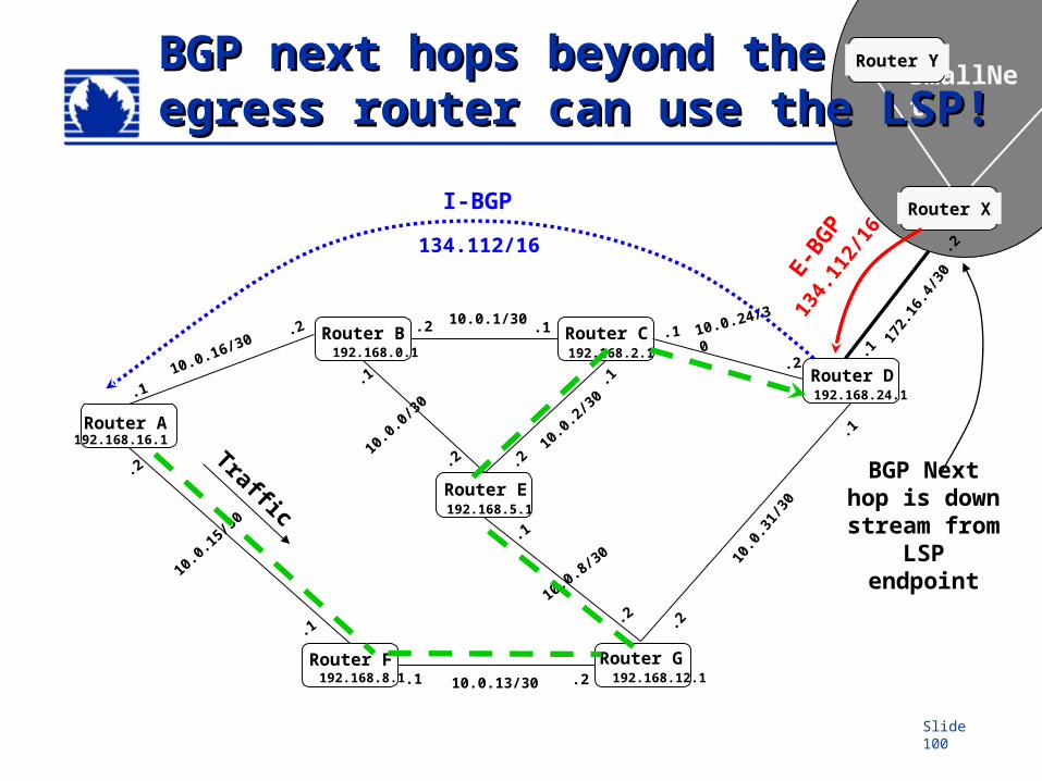
Router YBGP next hops beyond the BGP next hops beyond the egress router can use the LSP!egress router can use the LSP!
172.
16.4
/30
.2
.1
.2.1 10.0.13/30
134.
112/
16
E-BGP
134.112/16
I-BGP
BGP Next hop is down stream from
LSP endpoint
Traffic
Slide 101
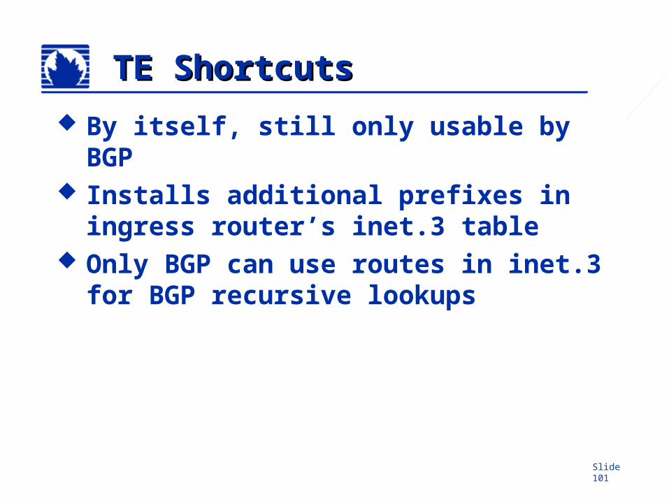
TE ShortcutsTE Shortcuts
By itself, still only usable by BGP Installs additional prefixes in
ingress router’s inet.3 table Only BGP can use routes in inet.3
for BGP recursive lookups
Slide 102
Router B Router C
Router E
Router D
.2
.1
10.0
.31/
30
Router GRouter F
192.168.16.1
192.168.0.1 192.168.2.1
192.168.5.1
192.168.8.1 192.168.12.1
192.168.24.1
Router A.1
.2
10.0.0/30
10.0.24/30.1
.2
10.0.1/30.1.2
10.0.8/30
.1
.210
.0.2
/30
.1
.2
10.0.16/30.2
.1
10.0.15/30
.2
.1
Router X
SmallNet
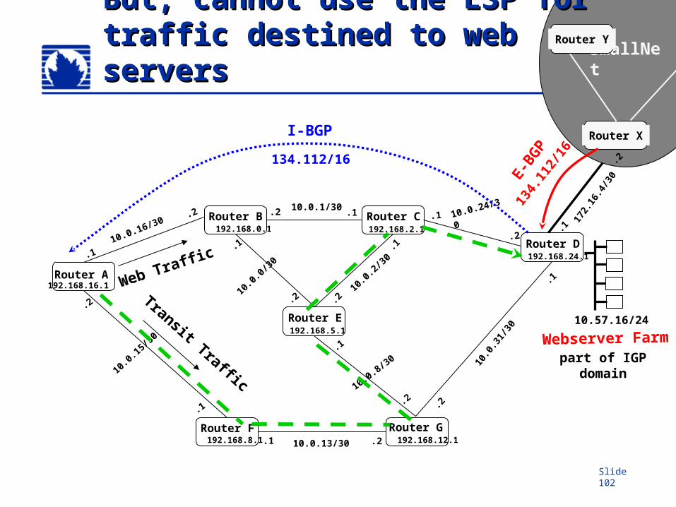
Router YBut, cannot use the LSP for But, cannot use the LSP for traffic destined to web serverstraffic destined to web servers
172.
16.4
/30
.2
.1
.2.1 10.0.13/30
134.
112/
16
E-BGP
134.112/16
I-BGP
Transit Traffic
Webserver Farm
10.57.16/24
part of IGP domain
Web Traffic
Slide 103
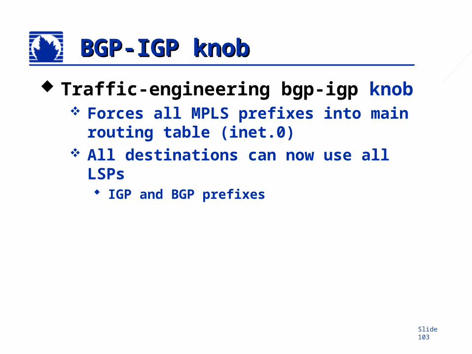
BGP-IGP knobBGP-IGP knob
Traffic-engineering bgp-igp knob Forces all MPLS prefixes into main
routing table (inet.0) All destinations can now use all LSPs
IGP and BGP prefixes
Slide 104
Router B Router C
Router E
Router D
.2
.1
10.0
.31/
30
Router GRouter F
192.168.16.1
192.168.0.1 192.168.2.1
192.168.5.1
192.168.8.1 192.168.12.1
192.168.24.1
Router A.1
.2
10.0.0/30
10.0.24/30.1
.2
10.0.1/30.1.2
10.0.8/30
.1
.210
.0.2
/30
.1
.2
10.0.16/30.2
.1
10.0.15/30
.2
.1
Router X
SmallNet
Router Y
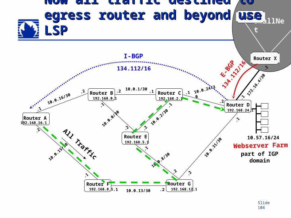
Now all traffic destined to Now all traffic destined to egress router and beyond use egress router and beyond use LSPLSP
172.
16.4
/30
.2
.1
.2.1 10.0.13/30
134.
112/
16
E-BGP
134.112/16
I-BGP
All Traffic
Webserver Farm
10.57.16/24
part of IGP domain
Slide 105
TTL DecrementTTL Decrement
Default is to decrement TTL on all LSR hops Loop prevention Topology discovery via traceroute
Disable TTL decrement inside LSP No topology discovery TTL decrement at egress router only
[edit protocols mpls label-switched-path lsp-path-name]
user@host# set no-decrement-ttl
Slide 106
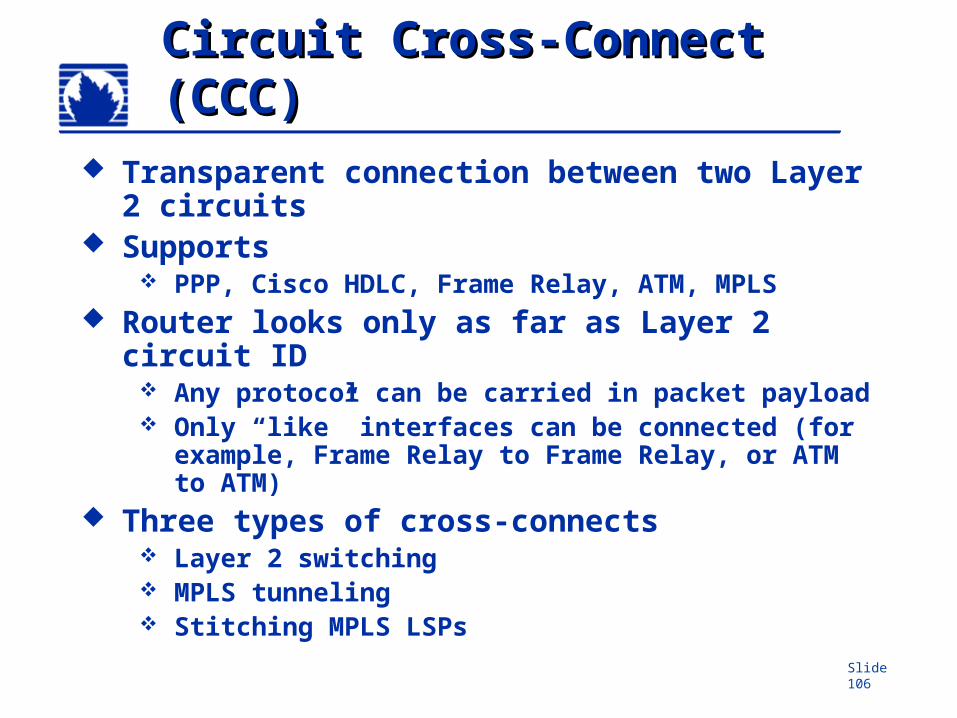
Circuit Cross-Connect Circuit Cross-Connect (CCC)(CCC)
Transparent connection between two Layer 2 circuits
Supports PPP, Cisco HDLC, Frame Relay, ATM, MPLS
Router looks only as far as Layer 2 circuit ID
Any protocol can be carried in packet payload Only “like” interfaces can be connected (for
example, Frame Relay to Frame Relay, or ATM to ATM)
Three types of cross-connects Layer 2 switching MPLS tunneling Stitching MPLS LSPs
Slide 107
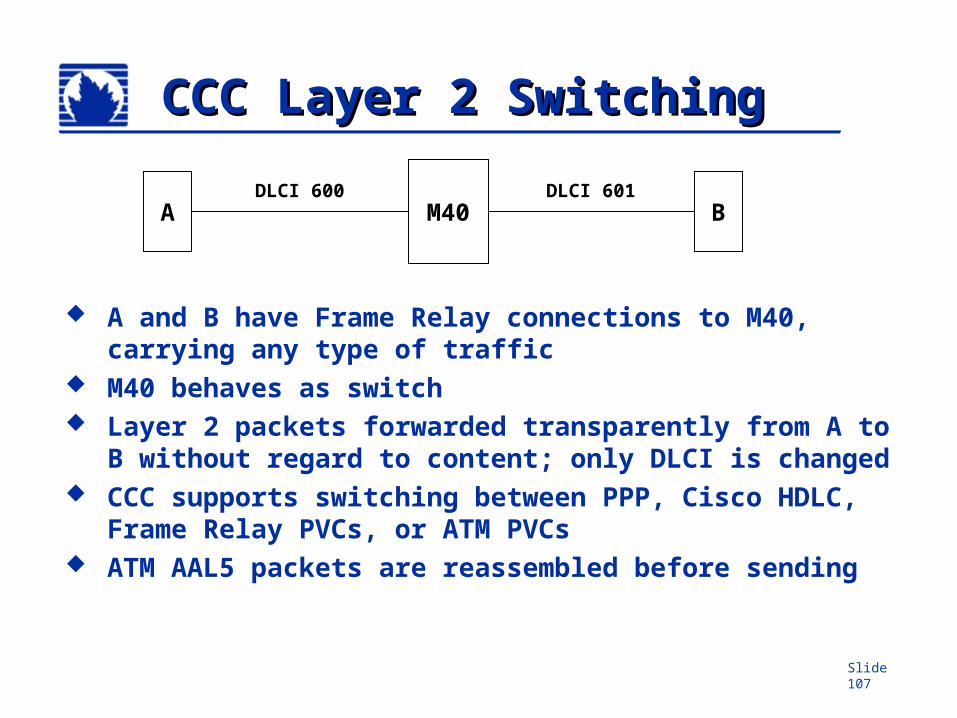
CCC Layer 2 SwitchingCCC Layer 2 Switching
A and B have Frame Relay connections to M40, carrying any type of traffic
M40 behaves as switch Layer 2 packets forwarded transparently from A to B
without regard to content; only DLCI is changed CCC supports switching between PPP, Cisco HDLC,
Frame Relay PVCs, or ATM PVCs ATM AAL5 packets are reassembled before sending
M40A BDLCI 600 DLCI 601
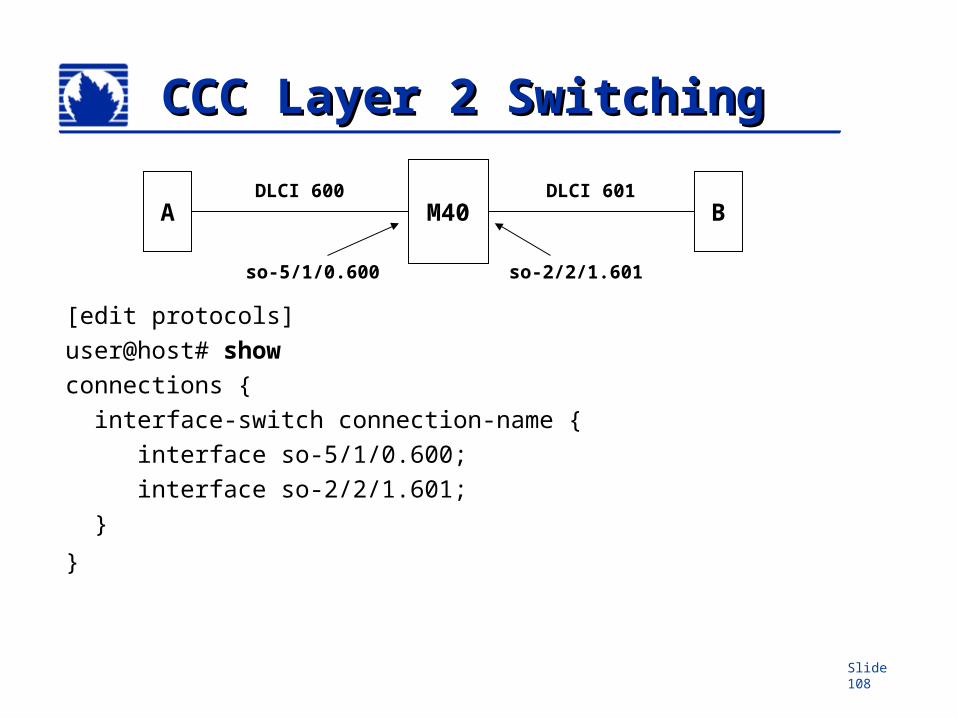
Slide 108
CCC Layer 2 SwitchingCCC Layer 2 Switching
[edit protocols]
user@host# show
connections {
interface-switch connection-name {
interface so-5/1/0.600;
interface so-2/2/1.601;
}
}
M40A BDLCI 600 DLCI 601
so-5/1/0.600 so-2/2/1.601
Slide 109
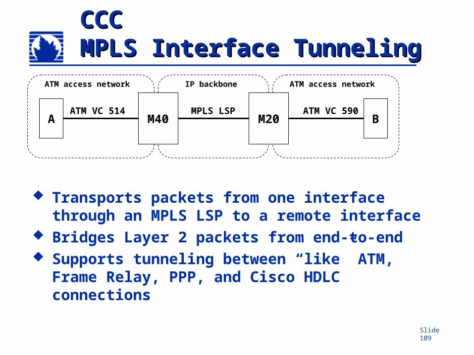
CCCCCCMPLS Interface TunnelingMPLS Interface Tunneling
Transports packets from one interface through an MPLS LSP to a remote interface
Bridges Layer 2 packets from end-to-end Supports tunneling between “like” ATM,
Frame Relay, PPP, and Cisco HDLC connections
A BATM VC 514 ATM VC 590
M20MPLS LSP
ATM access network ATM access networkIP backbone
M40
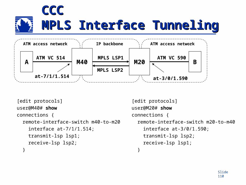
Slide 110
CCCCCCMPLS Interface TunnelingMPLS Interface Tunneling
[edit protocols]
user@M40# show
connections {
remote-interface-switch m40-to-m20
interface at-7/1/1.514;
transmit-lsp lsp1;
receive-lsp lsp2;
}
A BATM VC 514 ATM VC 590
M20MPLS LSP1
ATM access network ATM access networkIP backbone
M40MPLS LSP2
at-7/1/1.514
[edit protocols]
user@M20# show
connections {
remote-interface-switch m20-to-m40
interface at-3/0/1.590;
transmit-lsp lsp2;
receive-lsp lsp1;
}
at-3/0/1.590
Slide 111
CCC LSP StitchingCCC LSP Stitching
Large networks can be separated into several traffic engineering domains (supports IS-IS area partitioning)
CCC allows establishment of LSP across domains by “stitching” together LSPs from separate domains
TE domain 1
TE domain 2
TE domain 3 LSP stitching
LSR
LSR
LSR
LSRLSR
LSR
Slide 112
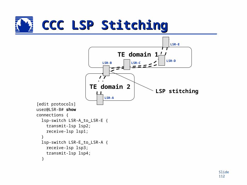
CCC LSP StitchingCCC LSP Stitching
[edit protocols] user@LSR-B# show connections { lsp-switch LSR-A_to_LSR-E { transmit-lsp lsp2; receive-lsp lsp1; } lsp-switch LSR-E_to_LSR-A { receive-lsp lsp3; transmit-lsp lsp4;
}
TE domain 1
TE domain 2LSP stitching
LSR-B LSR-CLSR-D
LSR-A
LSR-E