slide supports and height adjusters products
TRANSCRIPT
Slide Supports and Height Adjusters
6.0 2019
-10
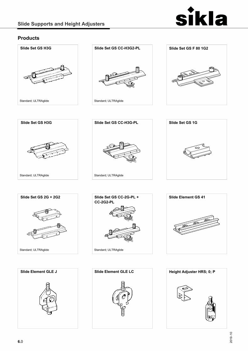
Products
Slide Set GS H3G
Standard; ULTRAglide
Slide Set GS CC-H3G2-PL
Standard; ULTRAglide
Slide Set GS F 80 1G2
Slide Element GS 41Slide Set GS CC-2G-PL + CC-2G2-PL
Standard; ULTRAglide
Slide Element GLE LC
Slide Set GS 2G + 2G2
Standard; ULTRAglide
Slide Set GS H3G
Standard; ULTRAglide
Slide Set GS CC-H3G-PL
Standard; ULTRAglide
Slide Set GS 1G
Slide Element GLE J Height Adjuster HRS; 0; P
Slide Supports and Height Adjusters
6.12019
-10
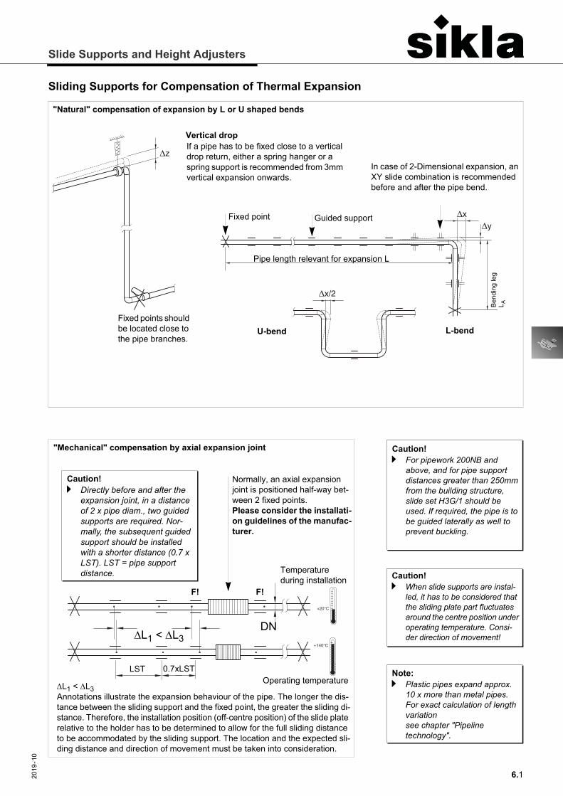
Sliding Supports for Compensation of Thermal Expansion
�x/2
�x�y
�zIf a pipe has to be fixed close to a vertical drop return, either a spring hanger or a spring support is recommended from 3mm vertical expansion onwards.
Fixed points should be located close to the pipe branches.
In case of 2-Dimensional expansion, an XY slide combination is recommended before and after the pipe bend.
"Natural" compensation of expansion by L or U shaped bends
Vertical drop
L-bendU-bend
Pipe length relevant for expansion L
Bend
ing
leg
L A
Fixed point Guided support
Caution!a Directly before and after the
expansion joint, in a distance of 2 x pipe diam., two guided supports are required. Nor-mally, the subsequent guided support should be installed with a shorter distance (0.7 x LST). LST = pipe support distance.
"Mechanical" compensation by axial expansion joint
L1 < L3 Annotations illustrate the expansion behaviour of the pipe. The longer the dis-tance between the sliding support and the fixed point, the greater the sliding di-stance. Therefore, the installation position (off-centre position) of the slide plate relative to the holder has to be determined to allow for the full sliding distance to be accommodated by the sliding support. The location and the expected sli-ding distance and direction of movement must be taken into consideration.
F!F!
+140°C
+20°C
Temperature during installation
Operating temperature
Normally, an axial expansion joint is positioned half-way bet-ween 2 fixed points.Please consider the installati-on guidelines of the manufac-turer.
L1 < L3DN
LST 0.7xLST
Caution!a For pipework 200NB and
above, and for pipe support distances greater than 250mm from the building structure, slide set H3G/1 should be used. If required, the pipe is to be guided laterally as well to prevent buckling.
Caution!a When slide supports are instal-
led, it has to be considered that the sliding plate part fluctuates around the centre position under operating temperature. Consi-der direction of movement!
Note:a Plastic pipes expand approx.
10 x more than metal pipes. For exact calculation of length variation see chapter "Pipeline technology".
Slide Supports and Height Adjusters
6.2 2019
-10
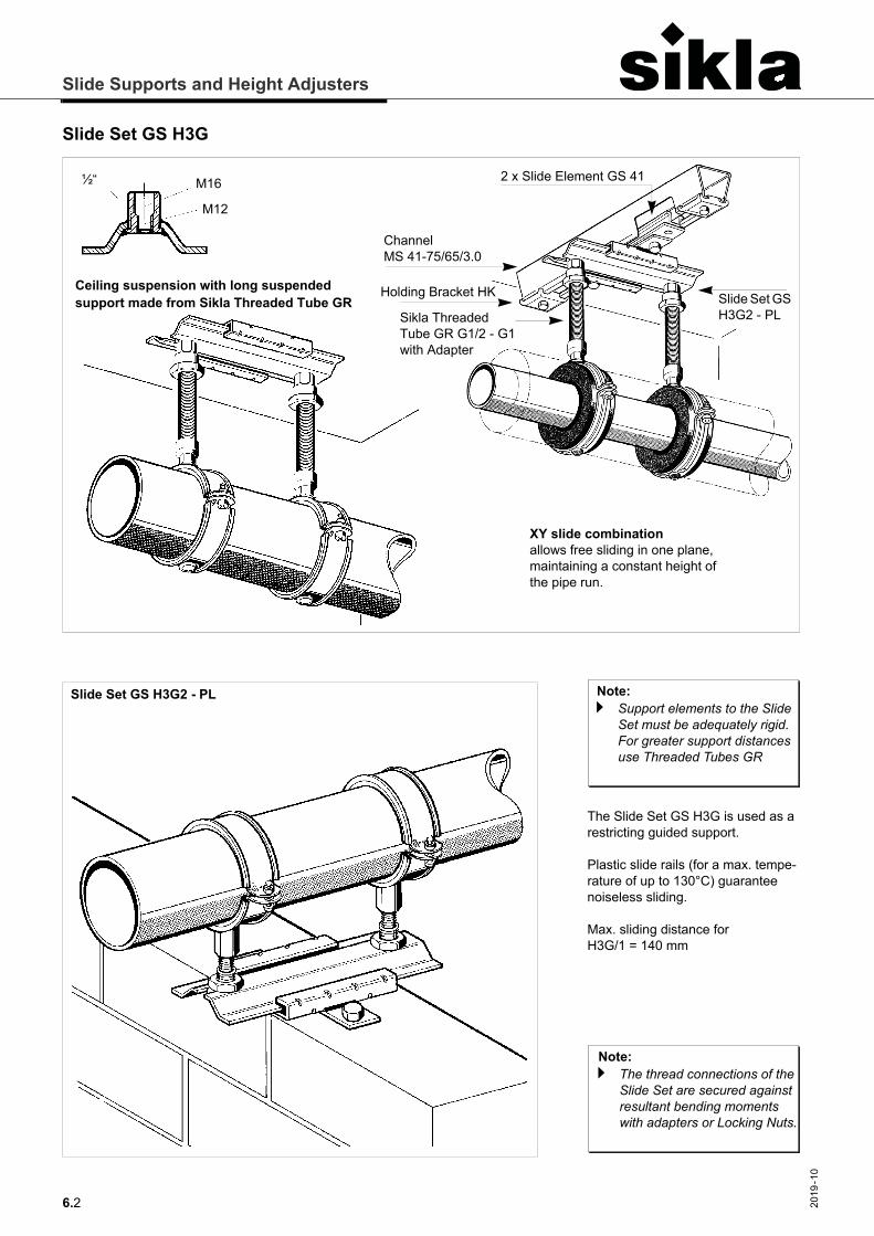
Slide Set GS H3G
½“ M16
M12
Channel MS 41-75/65/3.0
Holding Bracket HK
Sikla Threaded Tube GR G1/2 - G1with Adapter
2 x Slide Element GS 41
Slide Set GS H3G2 - PL
Ceiling suspension with long suspended support made from Sikla Threaded Tube GR
XY slide combination allows free sliding in one plane, maintaining a constant height of the pipe run.
Slide Set GS H3G2 - PL
The Slide Set GS H3G is used as a restricting guided support.
Plastic slide rails (for a max. tempe-rature of up to 130°C) guarantee noiseless sliding.
Max. sliding distance for H3G/1 = 140 mm
Note:a Support elements to the Slide
Set must be adequately rigid. For greater support distances use Threaded Tubes GR
Note:a The thread connections of the
Slide Set are secured against resultant bending moments with adapters or Locking Nuts.
Slide Supports and Height Adjusters
6.32019
-10
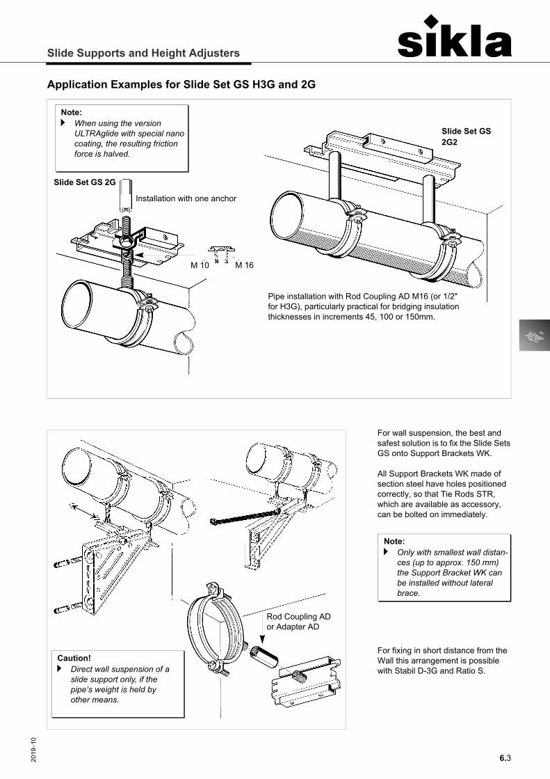
Application Examples for Slide Set GS H3G and 2G
M 16M 10
Slide Set GS 2G
Slide Set GS 2G2
Installation with one anchor
Pipe installation with Rod Coupling AD M16 (or 1/2" for H3G), particularly practical for bridging insulation thicknesses in increments 45, 100 or 150mm.
Note:a When using the version
ULTRAglide with special nano coating, the resulting friction force is halved.
Caution!a Direct wall suspension of a
slide support only, if the pipe‘s weight is held by other means.
Rod Coupling AD or Adapter AD
For wall suspension, the best and safest solution is to fix the Slide Sets GS onto Support Brackets WK.
All Support Brackets WK made of section steel have holes positioned correctly, so that Tie Rods STR, which are available as accessory, can be bolted on immediately.
For fixing in short distance from the Wall this arrangement is possible with Stabil D-3G and Ratio S.
Note:a Only with smallest wall distan-
ces (up to approx. 150 mm) the Support Bracket WK can be installed without lateral brace.
Slide Supports and Height Adjusters
6.4 2019
-10
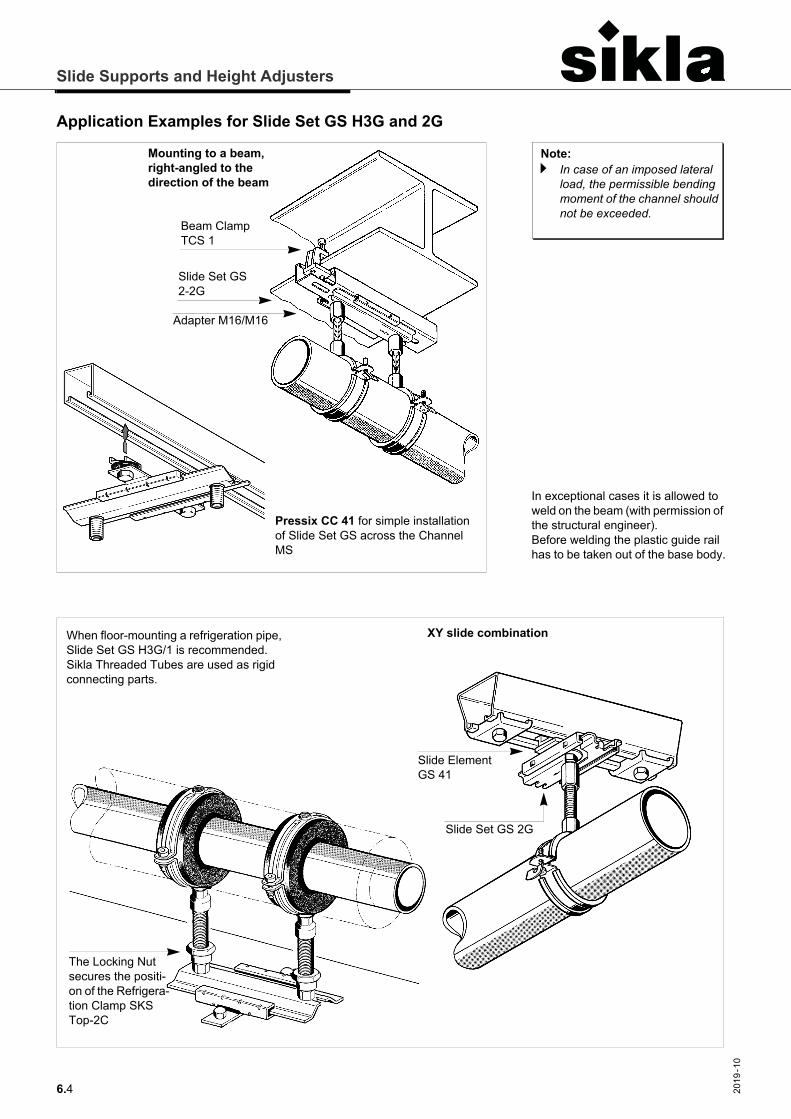
Application Examples for Slide Set GS H3G and 2G
In exceptional cases it is allowed to weld on the beam (with permission of the structural engineer).Before welding the plastic guide rail has to be taken out of the base body.
Note:a In case of an imposed lateral
load, the permissible bending moment of the channel should not be exceeded.
Beam Clamp TCS 1
Adapter M16/M16
Mounting to a beam, right-angled to the direction of the beam
Pressix CC 41 for simple installation of Slide Set GS across the Channel MS
Slide Set GS 2-2G
XY slide combination
Slide Element GS 41
Slide Set GS 2G
When floor-mounting a refrigeration pipe, Slide Set GS H3G/1 is recommended. Sikla Threaded Tubes are used as rigid connecting parts.
The Locking Nut secures the positi-on of the Refrigera-tion Clamp SKS Top-2C
Slide Supports and Height Adjusters
6.52019
-10
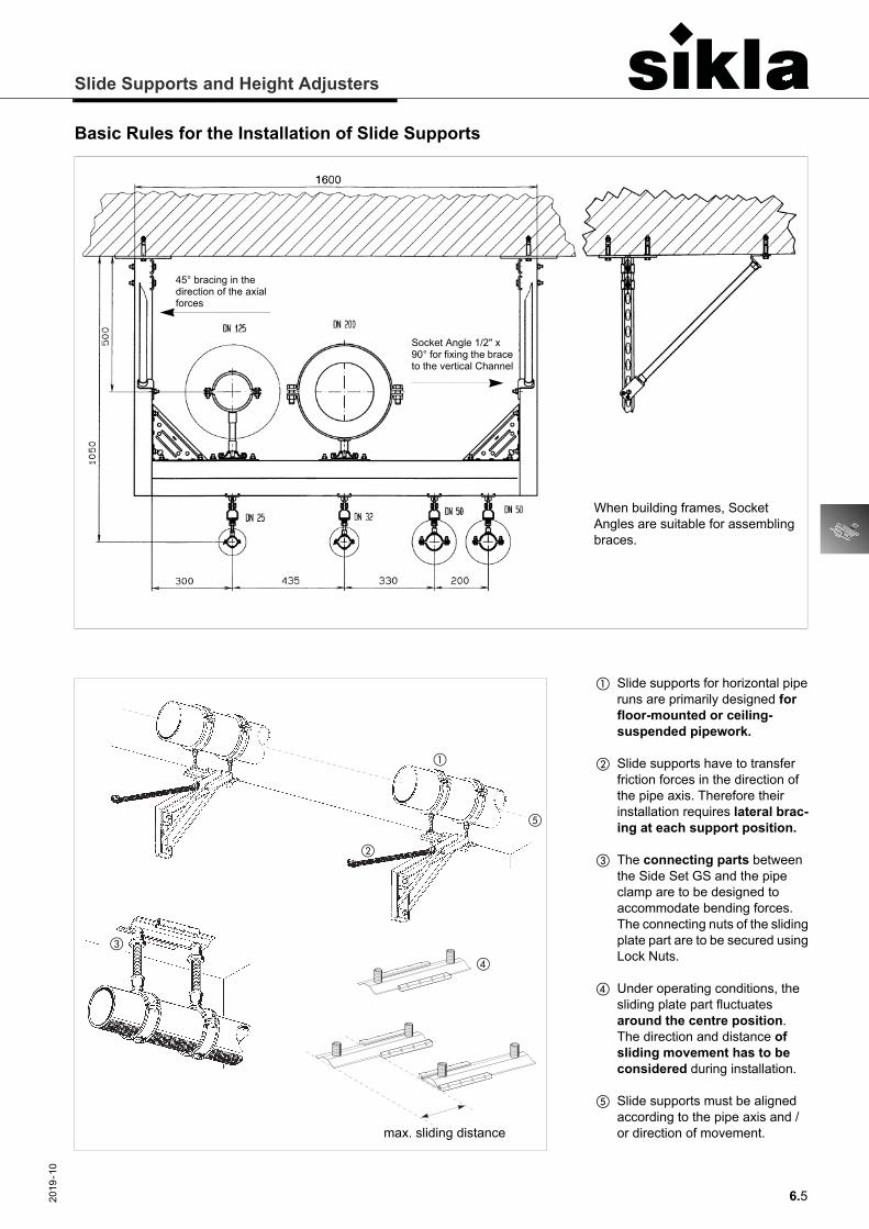
Basic Rules for the Installation of Slide Supports
When building frames, Socket Angles are suitable for assembling braces.
Socket Angle 1/2" x 90° for fixing the brace to the vertical Channel
45° bracing in the direction of the axial forces
�
�
�
�
�
max. sliding distance
� Slide supports for horizontal pipe runs are primarily designed for floor-mounted or ceiling-suspended pipework.
� Slide supports have to transfer friction forces in the direction of the pipe axis. Therefore their installation requires lateral brac-ing at each support position.
� The connecting parts between the Side Set GS and the pipe clamp are to be designed to accommodate bending forces. The connecting nuts of the sliding plate part are to be secured using Lock Nuts.
� Under operating conditions, the sliding plate part fluctuates around the centre position. The direction and distance of sliding movement has to be considered during installation.
� Slide supports must be aligned according to the pipe axis and / or direction of movement.
Slide Supports and Height Adjusters
6.6 2019
-10
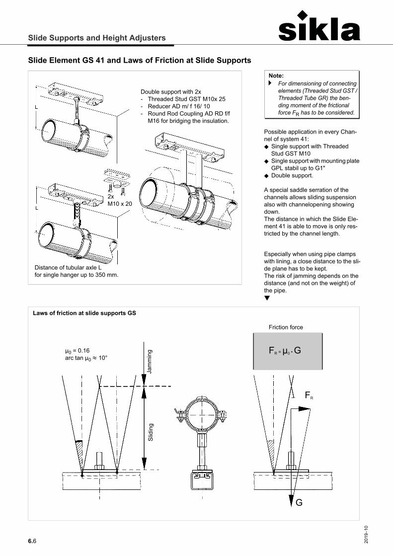
Slide Element GS 41 and Laws of Friction at Slide Supports
Laws of friction at slide supports GS
Slid
ing
µ0 = 0.16arc tan µ0 10°
Friction force
FR = µ0 • G
Jam
min
g
FR
G
Double support with 2x- Threaded Stud GST M10x 25- Reducer AD m/ f 16/ 10- Round Rod Coupling AD RD f/f
M16 for bridging the insulation.
Distance of tubular axle L for single hanger up to 350 mm.
2x M10 x 20
Possible application in every Chan-nel of system 41: Single support with Threaded
Stud GST M10 Single support with mounting plate
GPL stabil up to G1" Double support.
A special saddle serration of the channels allows sliding suspension also with channelopening showing down. The distance in which the Slide Ele-ment 41 is able to move is only res-tricted by the channel length.
Especially when using pipe clamps with lining, a close distance to the sli-de plane has to be kept.The risk of jamming depends on the distance (and not on the weight) of the pipe.
Note:a For dimensioning of connecting
elements (Threaded Stud GST / Threaded Tube GR) the ben-ding moment of the frictional force FR has to be considered.
Slide Supports and Height Adjusters
6.72019
-10
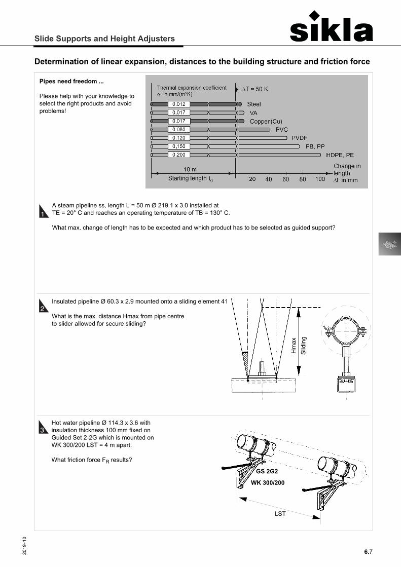
Determination of linear expansion, distances to the building structure and friction force
Pipes need freedom ...
Please help with your knowledge to select the right products and avoid problems!
A steam pipeline ss, length L = 50 m Ø 219.1 x 3.0 installed at TE = 20° C and reaches an operating temperature of TB = 130° C.
What max. change of length has to be expected and which product has to be selected as guided support?
1
2
3
Insulated pipeline Ø 60.3 x 2.9 mounted onto a sliding element 41.
What is the max. distance Hmax from pipe centre to slider allowed for secure sliding?
Hot water pipeline Ø 114.3 x 3.6 with insulation thickness 100 mm fixed on Guided Set 2-2G which is mounted on WK 300/200 LST = 4 m apart.
What friction force FR results?
Slid
ing
Hm
ax
GS 2G2
WK 300/200
LST
Slide Supports and Height Adjusters
6.8 2019
-10
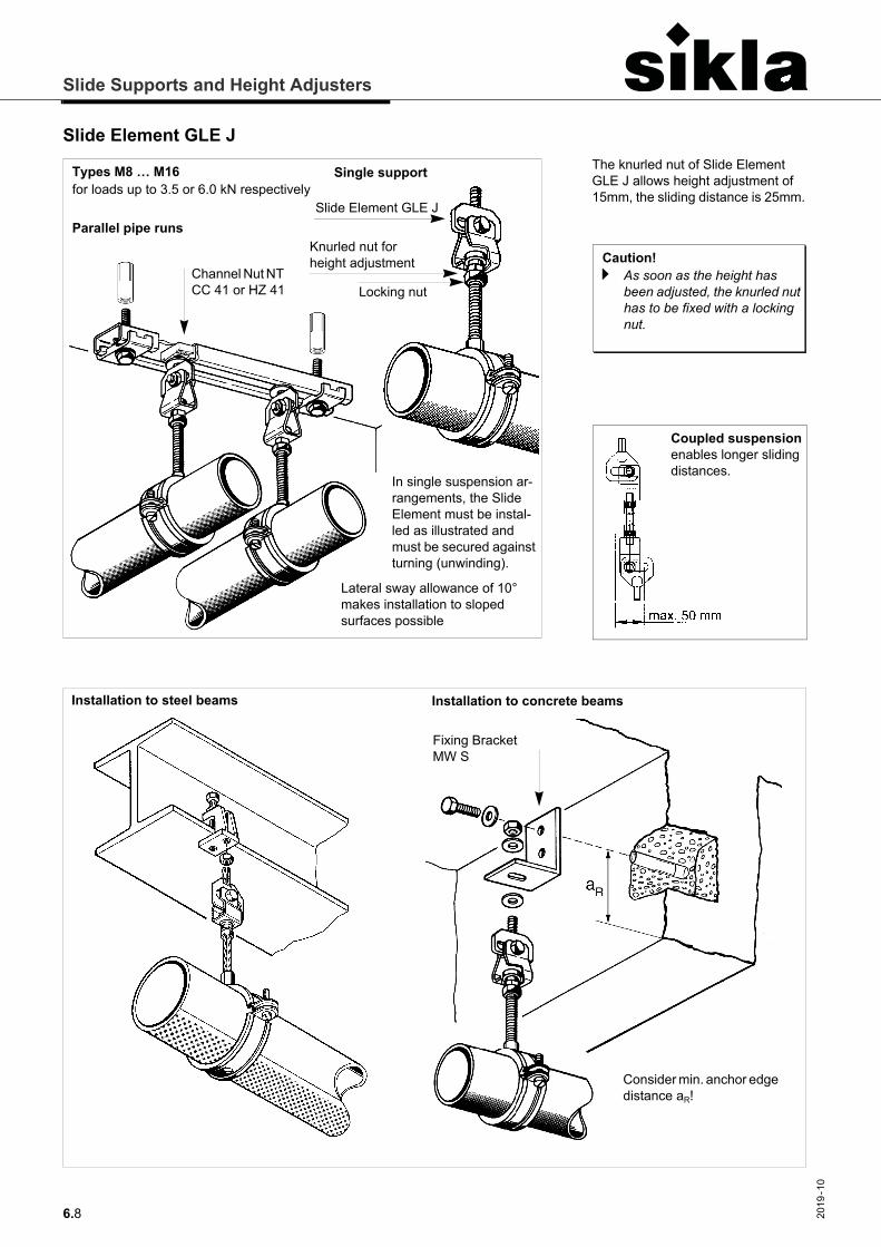
Slide Element GLE J
Channel Nut NT CC 41 or HZ 41
Parallel pipe runsSlide Element GLE J
Locking nut
Knurled nut for height adjustment
Single support
In single suspension ar-rangements, the Slide Element must be instal-led as illustrated and must be secured against turning (unwinding).
Types M8 … M16for loads up to 3.5 or 6.0 kN respectively
Lateral sway allowance of 10° makes installation to sloped surfaces possible
The knurled nut of Slide Element GLE J allows height adjustment of 15mm, the sliding distance is 25mm.
Caution!a As soon as the height has
been adjusted, the knurled nut has to be fixed with a locking nut.
Coupled suspensionenables longer sliding distances.
Fixing Bracket MW S
Consider min. anchor edge distance aR!
Installation to steel beams Installation to concrete beams
Slide Supports and Height Adjusters
6.92019
-10
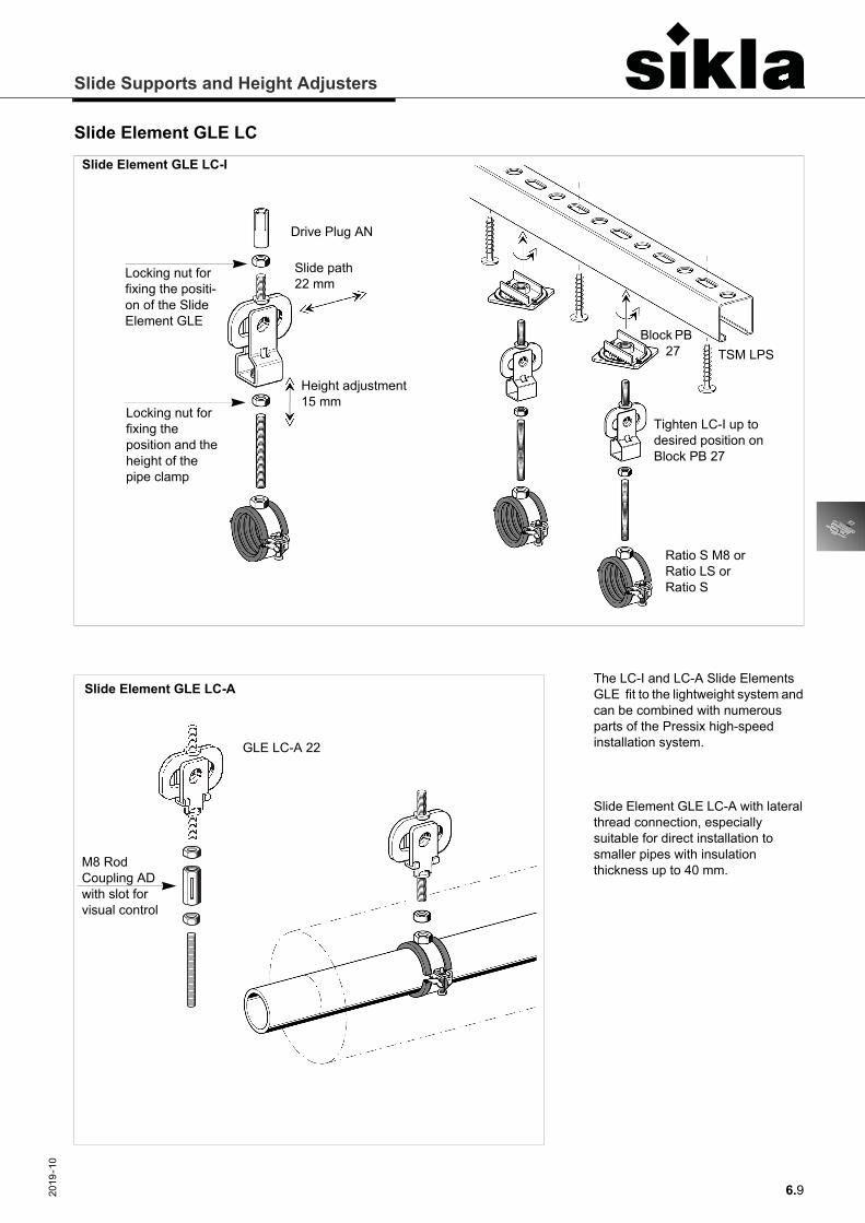
Slide Element GLE LCSlide Element GLE LC-I
Locking nut for fixing the positi-on of the Slide Element GLE
Locking nut for fixing the position and the height of the pipe clamp
Tighten LC-I up to desired position on Block PB 27
Drive Plug AN
Height adjustment 15 mm
TSM LPSBlock PB 27
Ratio S M8 orRatio LS orRatio S
Slide path 22 mm
The LC-I and LC-A Slide Elements GLE fit to the lightweight system and can be combined with numerous parts of the Pressix high-speed installation system.
Slide Element GLE LC-A with lateral thread connection, especially suitable for direct installation to smaller pipes with insulation thickness up to 40 mm.
GLE LC-A 22
Slide Element GLE LC-A
M8 Rod Coupling AD with slot for visual control
Slide Supports and Height Adjusters
6.10 2019
-10
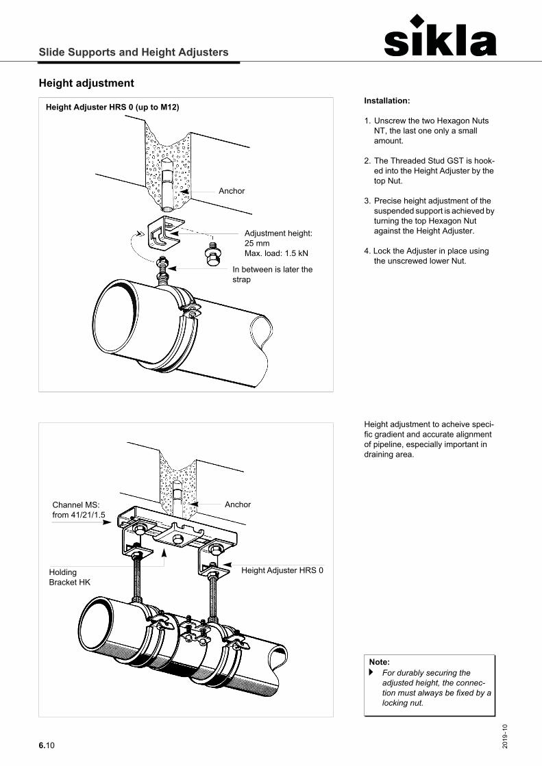
Height adjustment
Anchor
Adjustment height: 25 mmMax. load: 1.5 kN
In between is later the strap
Height Adjuster HRS 0 (up to M12)
Anchor
Height Adjuster HRS 0 Holding Bracket HK
Channel MS: from 41/21/1.5
Installation:
1. Unscrew the two Hexagon Nuts NT, the last one only a small amount.
2. The Threaded Stud GST is hook-ed into the Height Adjuster by the top Nut.
3. Precise height adjustment of the suspended support is achieved by turning the top Hexagon Nut against the Height Adjuster.
4. Lock the Adjuster in place using the unscrewed lower Nut.
Note:a For durably securing the
adjusted height, the connec-tion must always be fixed by a locking nut.
Height adjustment to acheive speci-fic gradient and accurate alignment of pipeline, especially important in draining area.
Slide Supports and Height Adjusters
6.112019
-10
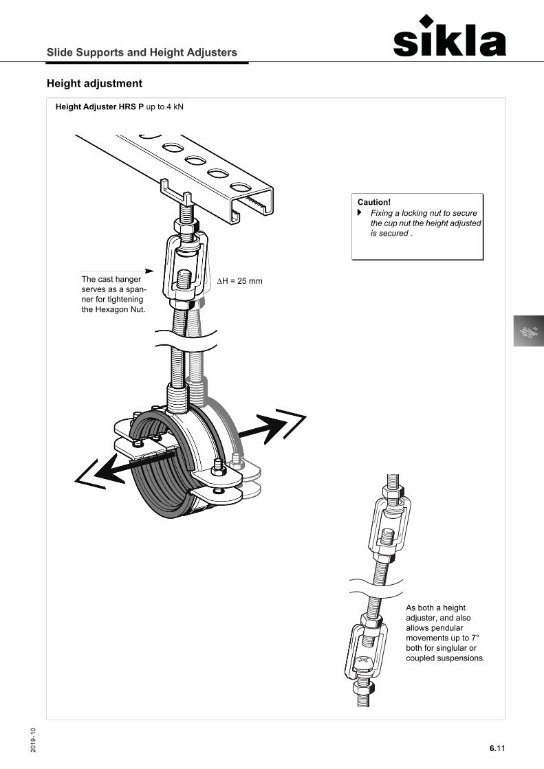
Height adjustment
The cast hanger serves as a span-ner for tightening the Hexagon Nut.
H = 25 mm
Height Adjuster HRS P up to 4 kN
As both a height adjuster, and also allows pendular movements up to 7° both for singlular or coupled suspensions.
Caution!a Fixing a locking nut to secure
the cup nut the height adjusted is secured .