slidelok ready for installation coupling - guenther … slidelok.pdfproject information approval...
TRANSCRIPT
GL-3.14
PROJECT INFORMATION APPROVAL STAMPProject: q Approved
Address: q Approved as noted
Contractor: q Not approved
Engineer: Remarks:
Submittal Date:
Notes 1:
Notes 2:
COUPLINGS
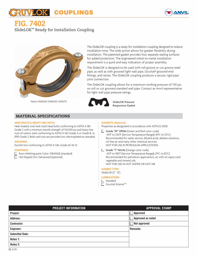
The SlideLOK coupling is a ready for installation coupling designed to reduce installation time. The slide action allows for greater flexibility during installation. The patented gasket provides four separate sealing surfaces for added protection. The engineered metal-to-metal installation requirement is a quick and easy indication of proper assembly.
The SlideLOK is designed to be used with roll groove or cut groove steel pipe, as well as with grooved light wall pipe, Gruvlok® grooved-end fittings, and valves. The SlideLOK coupling produces a secure, rigid pipe joint connection.
The SlideLOK coupling allows for a maximum working pressure of 750 psi on roll or cut grooved standard wall pipe. Contact an Anvil representative for light wall pipe pressure ratings.
Fig. 7402SlideLOK™ Ready for Installation Coupling
MATERiAL SPECiFiCATiONS
ANSI BOLTS & HEAVY HEX NUTS:Heat treated, oval neck track head bolts conforming to ASTM A 183 Grade 2 with a minimum tensile strength of 110,000 psi and heavy hex nuts of carbon steel conforming to ASTM A 563 Grade A or Grade B, or J995 Grade 2. Bolts and nuts are provided zinc electroplated as standard.
HOUSING:Ductile Iron conforming to ASTM A 536, Grade 65-45-12
COATINGS:q Rust inhibiting paint Color: ORANGE (standard)q Hot Dipped Zinc Galvanized (optional)
GASKETS: MaterialsProperties as designated in accordance with ASTM D 2000
q Grade “EP” EPDM (Green and Red color code) -40°F to 250°F (Service Temperature Range)(-40°C to 121°C) Recommended for water service, diluted acids, alkalies solutions, oil-free air and many other chemical services. NOT FOR USE IN PETROLEUM APPLICATIONS.
q Grade “T” Nitrile (Orange color code) -20°F to 180°F (Service Temperature Range)(-29°C to 82°C) Recommended for petroleum applications. air with oil vapors and vegetable and mineral oils. NOT FOR USE IN HOT WATER OR HOT AIR
GASKET TYPE:SlideLOK (2" - 8")
LUBRICATION:q Standardq Gruvlok XtremeTM
SlideLOK PressureResponsive Gasket
Patent D680629, D680630, D696751

COUPLINGS
GL-3.14
ZY
Xa
FIGURE 7402 SLIDELOK COUPLING
Nominal Size O.D. Max. Working
PressureMax.
End Load
Range of Pipe End
Separation
Coupling Dimensions Coupling Bolts Specified Torque § Approx. Wt. Ea.Xa Xb Y Z Qty. Size Min. Max.
In./DN(mm) In./mm PSI/bar Lbs./kN In./mm In./mm In./mm In./mm In./mm In./mm Ft.-Lbs/N-M Lbs./kg
2 2.375 750 3,323 0-1⁄32 33⁄4 33⁄8 6 2 2 1⁄2 x 23⁄4 80 100 2.950 60.3 51.7 14.78 0-0.79 95 86 152 51 M12 x 70 110 150 1.3
21⁄2 2.875 750 4,869 0-1⁄32 45⁄8 41⁄4 63⁄8 2 2 1⁄2 x 23⁄4 80 100 3.165 73.0 51.7 21.66 0-0.79 117 108 163 51 M12 x 70 110 150 1.4
3 3.500 750 7,216 0-1⁄32 51⁄5 411⁄16 7 2 2 1⁄2 x 31⁄2 80 100 3.680 88.9 51.7 32.10 0-0.79 132 119 178 51 M12 x 89 110 150 1.6
4 4.500 750 11,928 0-3⁄32 61⁄2 6 85⁄16 2 2 1⁄2 x 31⁄2 80 100 4.9100 114.3 51.7 53.06 0-2.38 165 152 212 51 M12 x 89 110 150 2.2
5 5.563 750 18,229 0-3⁄32 73⁄4 71⁄8 93⁄4 2 2 5⁄8 x 31⁄2 100 130 6.1125 141.3 51.7 81.09 0-2.38 196 181 248 51 M16 x 89 135 175 2.8
6 6.625 700 24,130 0-3⁄32 87⁄8 81⁄5 104⁄5 2 2 5⁄8 x 31⁄2 100 130 6.8150 168.3 48.3 107.34 0-2.38 224 208 274 51 M16 x 89 135 175 3.1
8 8.625 600 35,056 0-3⁄32 113⁄8 105⁄8 132⁄5 21⁄2 2 3⁄4 x 41⁄2 130 180 10.9200 219.1 41.4 155.94 0-2.38 289 270 340 64 M20 x 115 175 245 4.9
For additional details see “Coupling Data Chart Notes” on page 17.§ – For additional Bolt Torque information, see page 204.See Installation & Assembly directions on pages 164-165.Not for use in copper systems.
NOTE:Range of Pipe End Separation values are for roll grooved pipe and may be doubled for cut groove pipe.Impact gun can be used for installation, verify that the output of the impact gun is within the required torque range.
Fig. 7402SlideLOK™ Ready for Installation Coupling
ZY
Xb

COUPLINGS
GL-3.14
4 Final AssemblyThe SlideLOK coupling is
designed to achieve pad to pad (metal-to-metal contact) using either an impact wrench* or wrench. The intended torque range for the coupling is located in the Table 1. Securely tighten nuts alternately and equally until the housing halves are in metal-to-metal contact.
READY FOR iNSTALLATiON - RigHT OUT OF THE BOXDo not disassemble the SlideLOK™ Coupling. The Figure 7402 coupling is ready for installation. The bolt and gasket do not need to be removed.
1 Pipe Preparation— Pipe ends are to be rolled or cut grooved according to Anvil
specifications. The pipe end must be smooth and free from metal burrs or projections.
2 gasket Preparation— Ensure the gasket is suitable for the intended application
by referring to the Anvil gasket compatibility chart. Apply a light coating of Gruvlok® Xtreme™ Lubricant to exposed gasket surfaces.
3 Assembly— The SlideLOK Figure 7402 may be installed by one of two methods. The
preferred method depends on the type of pipe components being joined and their orientation. Please review both methods before installing.
METHOD #1Slide the SlideLOK coupling completely over the grooved pipe end. This will allow a clear and un-obstructed view of the pipe for correct alignment.
A. Slide the coupling on the pipe past the groove. The bolts and nuts can be hand tightened to position the coupling in place.
B. Align the mating pipe end. Align the two adjoining pipes together.
C. Slide the coupling back over the grooves so that the coupling keys are located over the respective grooves on both pipe ends.
D. Follow the instructions on fastening the coupling as shown in Step 4.
* CAUTION: When using an impact wrench, verify that the output of the impact wrench is within the required torque range. It is recommended that a torque wrench be used for accurate assembly in order to obtain specified performance.
5 Final inspectionEnsure the coupling is
properly aligned in the grooves and the housing halves are in metal-to-metal contact, depicted in the pictures to the right.
METHOD #2Slide the SlideLOK™ coupling half way onto the pipe end or fitting. This will better accommodate fitting, and valve accessories during installation.
A. Slide the coupling on the fitting so that the groove and keys are aligned.
B. Bring the pipe end or fitting towards the coupling and insert so that the groove and coupling keys are aligned.
C. Hand tighten the nuts to correctly position the couplings keys over the respective grooved ends.
D. Follow the instructions on fastening the coupling as shown in Step 4.
TABLE 1 – TORqUE RANGES
Sizes TorqueIn. Ft.-Lbs
2 - 4 80 - 1005 - 6 100 - 130
8 130 - 180
Fig. 7402SlideLOK™ Rigid Coupling
iNSTALLATiON

COUPLINGS
GL-3.14
TABLE 1 – TORqUE RANGES
Sizes TorqueIn. Ft.-Lbs
2 - 4 80 - 1005 - 6 100 - 130
8 130 - 180
REiNSTALLATiON OF THE FigURE 7402 SLiDELOK™ COUPLiNgThe SlideLOK coupling is designed to be installed in the ready for installation assembly position once. After the initial assemble the following steps are to be taken to re-install the Fig. 7402 SlideLOK coupling.
1De-pressurize the System— De-pressurize
the system before removing the SlideLOK Coupling. Dis-assemble the couplings by removing the nuts, bolts and gasket from the housing halves. A wrench is required to overcome the epoxy used to secure the nuts on the bolts.
2Pipe Preparation Pipe ends are to be rolled or
cut grooved according to Anvil specifications. The pipe end must be smooth and free from metal burrs or projections.
3gasket Preparation Ensure the gasket is suitable
for the intended application by referring to the Anvil gasket compatibility chart. A light coating of Gruvlok® XTreme™ lubricant must be applied to the gasket prior to installation.
4 Pipe Alignment and gasket installation
Slide the gasket onto the pipe then align the two pipe ends together. Pull the gasket into position, centering it between the grooves on each pipe. Gasket should not extend into the groove on either pipe.
5Housing AssemblyPlace each housing halves on
the pipe making sure the housing key fits into the groove. Be sure that the tongue and recess portions of the housing mate properly. Insert the bolts.
incorrect installation Examples
Low Torque or Out of Groove
Excess Torque or Shallow Groove Dimension
Fig. 7402SlideLOK™ Rigid Coupling
RE-iNSTALLATiON
6 Final AssemblyThe SlideLOK coupling is
designed to achieve pad to pad (metal-to-metal contact) using either an impact wrench* or wrench. The intended torque range for the coupling is located in the Table 1. Securely tighten nuts alternately and equally until the housing halves are in metal-to-metal contact.
7 Final inspectionEnsure the coupling is
properly aligned in the grooves and the housing halves are in metal-to-metal contact, depicted in the pictures to the right.
* CAUTION: When using an impact wrench, verify that the output of the impact wrench is within the required torque range. It is recommended that a torque wrench be used for accurate assembly in order to obtain specified performance.