sliding gate operator runner runner+ - sommer
TRANSCRIPT

EN TRANSLATION OF THE ORIGINAL INSTALLATION AND OPERATING MANUAL
Sliding gate operatorRUNnerRUNner+
RUNner+_S10320-00001_262021_0-DRE_Rev-F_EN
Download the current manual:
SomloqRollingcode

Additional connection options
2
Table of contentsGeneral Information ..................................................3
Symbols .......................................................................... 3Safety instructions .......................................................... 3Intended use ................................................................... 4Permitted gate wing dimensions .................................... 4Technical data ................................................................ 4Dimensions ..................................................................... 5
Installation preparations ...........................................6Safety instructions .......................................................... 6Tools required ................................................................. 6Personal protective equipment ....................................... 6Scope of supply .............................................................. 6Tips for installation .......................................................... 7General preparations ...................................................... 7
Installation ..................................................................8Safety instructions .......................................................... 8Foundation ..................................................................... 8Installation on ground ..................................................... 8Installing the racks .......................................................... 9Adjusting the backlash ................................................. 10
Connection ...............................................................11Safety instructions .........................................................11Installation location ........................................................11Mains connection ......................................................... 12Connecting safety devices ........................................... 12Connecting button ........................................................ 14Potential-free relay contact ........................................... 14Optional connections .................................................... 15Battery pack ................................................................. 15External antenna .......................................................... 16
Initial operation ........................................................17Safety instructions ........................................................ 17Connecting the power supply ....................................... 17Installing limit switches ................................................. 17Resetting the control unit .............................................. 19Teach-in run .................................................................. 19Radio receiver (version Somloq Rollingcode) .............. 20Radio receiver (version SOMloq2) ............................... 21Concluding commissioning ........................................... 24
Operation ..................................................................25Safety instructions ........................................................ 25Opening the gate .......................................................... 25Closing the gate ........................................................... 25Partial opening ............................................................. 25Automatic closing function ............................................ 26Pre-warning time .......................................................... 26Dead man button mode ................................................ 26Obstruction detection ................................................... 27Power-saving mode ...................................................... 27Overload protection ...................................................... 27Operation after a power failure ..................................... 27Emergency release ...................................................... 28
Maintenance and care .............................................29Safety instructions ........................................................ 29Regular testing ............................................................. 29
Troubleshooting ......................................................30Description of the flash sequences of the LEDs ........... 30
Disassembly and disposal......................................31Disassembly ................................................................. 31Disposal ........................................................................ 31Warranty and customer service .................................... 31
DIP switch settings ..................................................31Connection diagram ................................................32

General Information
3
General InformationSymbols
ATTENTION SYMBOL:Important safety instructions!To ensure the safety of personnel it is important to follow all the instructions. Save these instructions!
IMPORTANT INFORMATION SYMBOL:Information, useful advice!Refers to a respective picture in the introduction or main text.
Safety instructionsGeneral
¾ These installation and operating instructions must be read, understood and complied with by persons who install, use or perform maintenance on the drive.
¾ Keep this installation and operating manual accessible at all times. ¾ Installation, connection and initial commissioning of the drive may only
be carried out by technically knowledgeable persons. ¾ All electrical leads must be laid immovably and secured against
displacement. ¾ Install the drive on correctly aligned gates only. An improperly aligned
gate can cause serious injuries or damage the drive. ¾ The manufacturer assumes no liability for injuries, damage or break-
downs that occur due to non-compliance with the installation and operating instructions.
¾ Always ensure compliance with accident prevention regulations and current standards in each respective country.
¾ Take heed of and comply with the “ASR A1.7 Technical Regulations for Workplaces” of the committee for workplaces (ASTA). (Applies to operators in Germany).
¾ Before any work on the drive disconnect it from the power supply and lock it to prevent reconnection. This also includes disconnection of a battery, if present.
¾ Only use OEM (Original Equipment Manufacturer) spare parts, accessories and mounting material.
Storage ¾ The drive must be stored in an enclosed, dry area at a room
temperature of –20 °C to +50 °C. ¾ The drive should be stored horizontally.
–20 °C
+50 °C
Operation ¾ The drive must be operated only if a non-hazardous force tolerance
is set or safety is guaranteed by other safety equipment. The force tolerance must be set low enough to eliminate any danger of injury by the closing force (see “Maintenance and care”).
¾ RUNner: No active safety contact strip on the main closing edge necessary. Passive rubber profile edge sufficient.
¾ RUNner+: A active safety contact strip must be attached as a closing edge safety device.
¾ Never reach into an operating gate or moving parts. ¾ Do not drive through the gate until it is fully open. ¾ There is danger due to the crushing and shearing points presented
by the mechanism and the closing edges of the gate. ¾ For automatic closing the main and auxiliary closing edges must be
secured in accordance with the applicable directives and standards. ¾ Open and close the gate only if there are no children, persons, animals
or objects within its area of movement. ¾ Regularly check the safety and protection functions and repair faults
when they are detected. See “Care and maintenance”.
Radio remote control ¾ The remote control must only be used for devices and systems in which
radio interference will not endanger people, animals or objects or the risk is reduced by other safety devices.
¾ The user must be informed that the remote control of equipment that presents a risk of accident may take place, if at all, only when there is direct visual contact with the equipment.
¾ The radio remote control may only be used if the door’s movement can be watched and no persons or objects are within the range of movement.
¾ Store the handheld transmitter so that unintended operation, e.g., by children or animals, is impossible.
¾ The operator of the radio system is not protected from faults due to other telecommunications equipment or devices (e.g. radio-controlled systems that are licensed to operate in the same frequency range). If substantial interference occurs, please contact your appropriate telecommunications office which has radio interference measuring equipment (radiolocation)!
¾ Do not operate the handheld transmitter in areas with sensitive radio communications or systems (e.g. airports, hospitals).
Type plate ¾ The type plate is attached to the inside of the base frame/housing.
The type plate shows the exact type drawing and the date of manufacture (month/year) of the drive.

General Information
4
Intended use• The drive is designed exclusively for opening and closing sliding gates
(see EN 12433-1), referred to below as gates. Any other use does not constitute intended use. The manufacturer accepts no liability resulting from use other than intended use. The user bears the sole responsibility for any risk involved. It also voids the warranty.
• Gates automated with a drive must comply with all currently valid standards and directives: e.g. EN 12604, EN 12605.
• Maintain the safety clearances between the gate and surroundings as specified in EN 12604.
• Use the drive only in technically flawless condition, in compliance with its intended use, conscious of safety and hazards subject to compliance with the installation and operating instructions.
• Position the running rail to allow water to drain to prevent ice accumulation in winter.
• The gate must move freely in the guide and on the running rail to allow the drive to react sensitively and the gate to be switched off in emergency.
• The gate must have end stops in open and closed position, otherwise it may be pushed out of the guide in the event of an emergency release.
• Malfunctions which could affect safety must be corrected immediately.
• The gate must be stable and torsionally stiff, i.e. it must not bend or twist when being opened or closed.
• The drive cannot compensate for any defects in the gate or incorrect installation of the gate.
• Do not install the drive in potentially explosive areas.
• Do not operate the drive in rooms with corrosive atmospheres.
Simplified declaration of conformitySOMMER Antriebs- und Funktechnik GmbH hereby declares that the radio system (RUNner/RUNner+) complies with Directive 2014/53/EU. You can see the full text of the EU Declaration of Conformity for the radio system at:
https://som4.me/mrl
Permitted gate wing dimensionsRUNner RUNner+
Gate inclination: 0 % at 0 % max.5 %*
Min. movement range:
min. 1,400 mm min. 1,400 mm min. 1,400 mm
Max. movement range:
max. 8,000 mm
max. 12,000 mm
max. 8,000 mm
Weight: max. 600 kg max. 800 kg max. 500 kg
* Gates operated in combination with a RUNner+, must not have an inclination of more than 5% and must comply with the valid standards and directives, in particular EN 12604. Radial dampers are recommended with lift gates. However, these merely optimise speed regulation and do not in any way guarantee safety.
• RUNner: No active safety contact strip on the main closing edge necessary. Passive rubber profile edge sufficient.
• RUNner+: A active safety contact strip must be attached as a closing edge safety device.
Technical dataRUNner RUNner+
Rated voltage AC 220–240 V
Rated frequency 50–60 Hz
Storage locations in radio receiver 112* | 40/450**
Operating temperature range –30 to +50 °C
IP code IP54
max. torque 20 Nm 28 Nm
Rated torque 6 Nm 8,4 Nm
Rated current consumption 0.54 A
Rated wattage 125 W
Max. speed 210 mm/s 190 mm/s
Power consumption, standby 0,5 W
Weight ≈10 kg
Operating time S3 40 %
Properties of the pinion Module 4/19 teeth
Workplace-related emission value <75 dB(A) – drive only
* 112 Somloq Rollingcode
** 40 SOMloq2 (Memo 450)

General Information
5
DimensionsAll dimensions are in millimetres. The drive is locked.
4991
84
314
169
304
140,5
277,5
12845
Gear housing
40,140,3
14,332,1
Declaracion of incorporationfor the installation of an incomplete machine in accordance
with the Machinery Directive 2006/42/EC, Appendix II, Section 1 B
SOMMER Antriebs- und Funktechnik GmbHHans-Böckler-Straße 27 73230 Kirchheim/Teck
Germanyhereby declares that the operator
RUNner / RUNner+
was designed, developed and manufactured in compliance with
• Machinery Directive 2006/42/EC• Low Voltage Directive 2014/35/EU• Directive on Electromagnetic Compatibility 2014/30/EU• RoHS Directive 2011/65/EU.
The following norms were used:
• EN ISO 13849-1, PL “C” Cat. 2
Safety of electrical appliances/operators for gates
• EN 60335-1/2, where applicable
Safety of machines – Safety-related parts of con-trols – Part 1: General design guidelines
• EN 61000-6-3 Electromagnetic compatibility (EMC) – interference• EN 61000-6-2 Electromagnetic compatibility (EMC) – interference
resistance• EN 60335-2-103 General safety requirements for household and
similar electrical appliances – Part 2: Special requirements for operators for gates, doors and windows
The following requirements of Annex 1 of the Machinery Directive 2006/42/EC are met: 1.1.2, 1.1.3, 1.1.5, 1.2.1, 1.2.2, 1.2.3, 1.2.4, 1.2.6, 1.3.2, 1.3.4, 1.3.7, 1.5.1, 1.5.4, 1.5.6, 1.5.14, 1.6.1, 1.6.2, 1.6.3, 1.7.1, 1.7.3, 1.7.4 The special technical documentation was prepared in accordance with Annex VII Part B and will be submitted to regulators electronically on request.
The incomplete machine is intended for installation in a gate system only to form a complete machine as defined by the Machinery Directive 2006/42/EC. The gate system may only be put into operation after it has been established that the complete system complies with the regulations of the above EC Directive.
The undersigned is responsible for compilation of the technical documents.
Kirchheim, 20.04.2016
i.V.
Jochen Lude Responsible for documents
6
Installation preparationsSafety instructions
ATTENTION!Follow all installation directions. Improper installation can lead to serious injuries.
• The mains voltage must correspond with the voltage listed on the drive type plate.
• The contacts of all devices to be connected externally must be safely isolated from the mains voltage supply in accordance with the standard IEC 60364-4-41.
• Comply with the standard IEC 60364-4-41 when laying the leads of the external devices.
• The drive may be installed, connected and commissioned by competent personnel only.
• Do not move the gate, if there are any people, animals or objects in the area of movement.
• Keep children, disabled persons and animals away from the gate.
• Wear safety glasses when drilling the fastening holes.
• Cover the drive during drilling to prevent dirt from entering the drive unit.
ATTENTION!The foundation must be solid and stable. Only install the drive on a correctly aligned gate. An incorrectly aligned gate could cause serious injury.
• Remove any gate locks or render them inoperative.
• Use only approved fasteners (e.g. anchor fittings, bolts). The fasteners must match the material of the ground.
• Check the gate for smooth operation.
Tools required
10 mm 10 mm13 mm8 mm
10 mm13 mm
Personal protective equipment
• Safety glasses (for drilling).
• Work gloves.
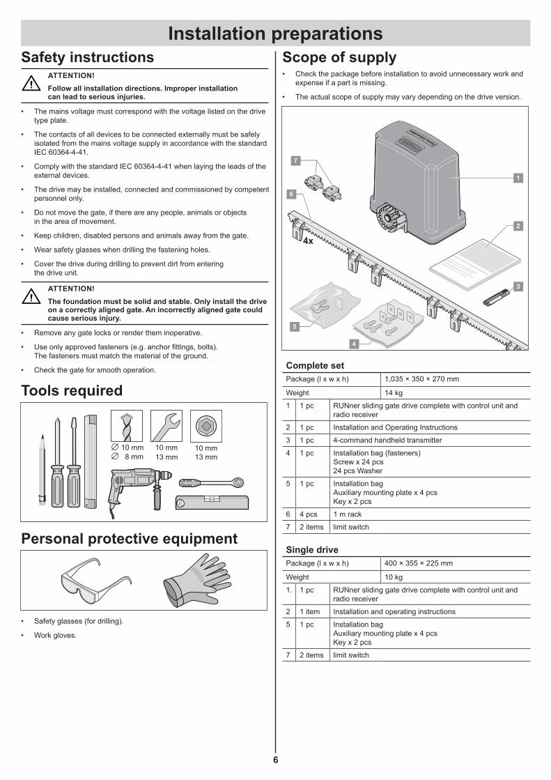
Scope of supply• Check the package before installation to avoid unnecessary work and
expense if a part is missing.
• The actual scope of supply may vary depending on the drive version.
7
2
4x
1
4
6
3
5
Complete setPackage (l x w x h) 1,035 × 350 × 270 mm
Weight 14 kg
1 1 pc RUNner sliding gate drive complete with control unit and radio receiver
2 1 pc Installation and Operating Instructions
3 1 pc 4-command handheld transmitter
4 1 pc Installation bag (fasteners)Screw x 24 pcs24 pcs Washer
5 1 pc Installation bagAuxiliary mounting plate x 4 pcsKey x 2 pcs
6 4 pcs 1 m rack
7 2 items limit switch
Single drivePackage (l x w x h) 400 × 355 × 225 mm
Weight 10 kg
1. 1 pc RUNner sliding gate drive complete with control unit and radio receiver
2 1 item Installation and operating instructions
5 1 pc Installation bag Auxiliary mounting plate x 4 pcsKey x 2 pcs
7 2 items limit switch

Installation preparations
7
SOMMERTORANTRIEBE
01
2
MCP
E
MCS
O
9
AC 230 V
2 x 0,75 mm²
1
2
8
4 x 0,75 mm²7
3 x 1,5 mm²
4
32 x 0,75 mm²
5
6
4 x 0,75 mm²
3
2 x 0,75 mm²
7
Tips for installation• A safety device must always be connected as an NC contact.
This ensures that safety is always guaranteed in the event of tripping or a fault.
• Determine the position of the accessories before installation together with the operator.
1 Warning light DC 24 V, 25 W, max. 0.8 A
2 Key switch (1 or 2 contact)
3 Light barrier (prescribed for automatic closing, see EN 12543)
4 Console
5 Main switch (lockable)
6 Rod antenna (including 10 m cable)
7 Safety contact strip (8.2 kohm, Fraba system)
8 Telecody unit
9 Car/wall holder for handheld transmitter
General preparations• Remove or disable all locking devices (electric lock, bars, etc.) before
installing the drive.
• The gate must not show excessive lateral deviation throughout its range of movement.
• The system wheels and bottom track and the roller and top guide must operate without excessive friction.
• Install empty ducts under the gate for the cables of the mains supply line and the accessories (light barrier, warning light, key switch, etc.).
IMPORTANT INFORMATION!To prevent the ingress of water, the wiper must be located behind the cover, as shown.
Installation
8
InstallationSafety instructions
¾ The control unit must be connected to the power supply by an electrician only.
¾ Ensure that the drive is securely fastened to the ground and the racks on the gate to withstand the high forces generated when opening and closing the gate.
¾ If a button is used for opening or closing, it must be installed at a height of at least 1.6 m to prevent operation by children.
¾ The rack must not press on the pinion during operation, otherwise the drive will be damaged.
¾ Follow the standards for installation, e.g.: EN 12604, EN 12605.
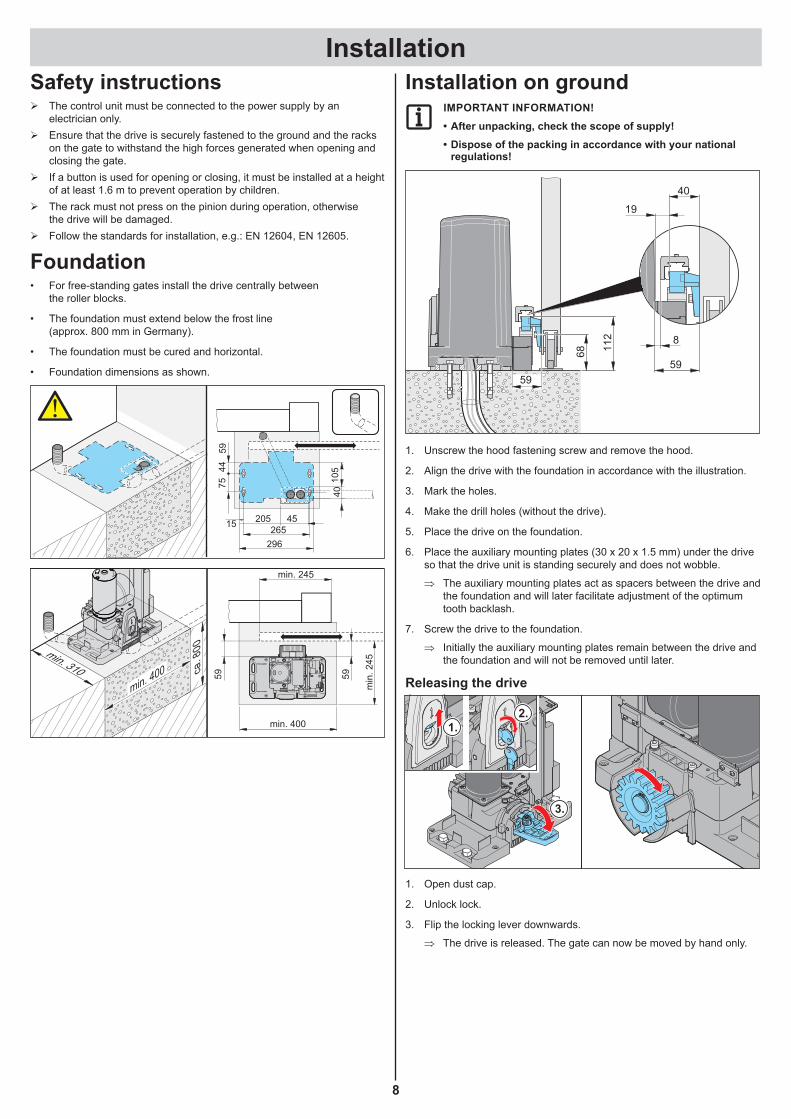
Foundation• For free-standing gates install the drive centrally between
the roller blocks.
• The foundation must extend below the frost line (approx. 800 mm in Germany).
• The foundation must be cured and horizontal.
• Foundation dimensions as shown.
7544
59
4010
5
4520515
296265
min. 310 ca. 8
00
min. 400
min. 245
min. 400
min
.245
59 59
Installation on groundIMPORTANT INFORMATION!• After unpacking, check the scope of supply!• Dispose of the packing in accordance with your national
regulations!
59
68
59
112
19
8
40
1. Unscrew the hood fastening screw and remove the hood.
2. Align the drive with the foundation in accordance with the illustration.
3. Mark the holes.
4. Make the drill holes (without the drive).
5. Place the drive on the foundation.
6. Place the auxiliary mounting plates (30 x 20 x 1.5 mm) under the drive so that the drive unit is standing securely and does not wobble.
⇒ The auxiliary mounting plates act as spacers between the drive and the foundation and will later facilitate adjustment of the optimum tooth backlash.
7. Screw the drive to the foundation.
⇒ Initially the auxiliary mounting plates remain between the drive and the foundation and will not be removed until later.
Releasing the drive
2.1.
3.
1. Open dust cap.
2. Unlock lock.
3. Flip the locking lever downwards.
⇒ The drive is released. The gate can now be moved by hand only.
Installation
9
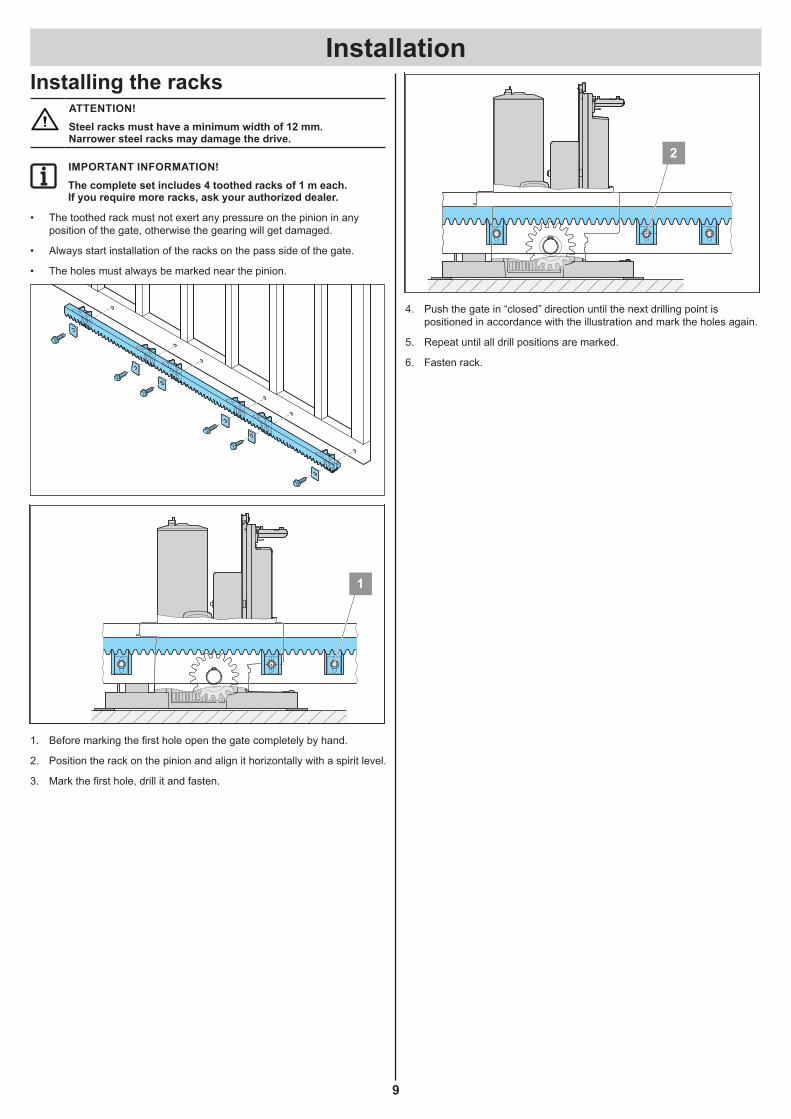
Installing the racksATTENTION!Steel racks must have a minimum width of 12 mm. Narrower steel racks may damage the drive.
IMPORTANT INFORMATION!The complete set includes 4 toothed racks of 1 m each. If you require more racks, ask your authorized dealer.
• The toothed rack must not exert any pressure on the pinion in any position of the gate, otherwise the gearing will get damaged.
• Always start installation of the racks on the pass side of the gate.
• The holes must always be marked near the pinion.
1
1. Before marking the first hole open the gate completely by hand.
2. Position the rack on the pinion and align it horizontally with a spirit level.
3. Mark the first hole, drill it and fasten.
2
4. Push the gate in “closed” direction until the next drilling point is positioned in accordance with the illustration and mark the holes again.
5. Repeat until all drill positions are marked.
6. Fasten rack.
Installation
10
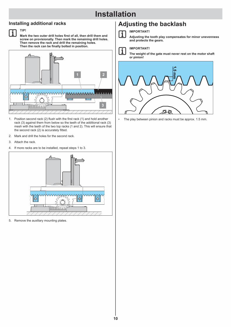
Installing additional racksTIP!Mark the two outer drill holes first of all, then drill them and screw on provisionally. Then mark the remaining drill holes. Then remove the rack and drill the remaining holes. Then the rack can be finally bolted in position.
2
3
1
1. Position second rack (2) flush with the first rack (1) and hold another rack (3) against them from below so the teeth of the additional rack (3) mesh with the teeth of the two top racks (1 and 2). This will ensure that the second rack (2) is accurately fitted.
2. Mark and drill the holes for the second rack.
3. Attach the rack.
4. If more racks are to be installed, repeat steps 1 to 3.
5. Remove the auxiliary mounting plates.
Adjusting the backlashIMPORTANT!Adjusting the tooth play compensates for minor unevenness and protects the gears.
IMPORTANT!The weight of the gate must never rest on the motor shaft or pinion!
1,5 mm
• The play between pinion and racks must be approx. 1.5 mm.

Connection
11
Connection
8
TR
L1 L N N
10 12 14 16 18
7 9 11 13 15 17
20 22 24 26 28 30
19 21 23 25 27 29
100%START
PROG 75%50%
25%
0%
MAX
MAX
0
Limit
Limit
Stat
usSa
fety Li
ght
Rel
ay
1
ON
ECE
2 3 4 5 6 7 8
8
9
10
12
1115
18
19
14 13
541 32
16
17
20
6
7
1. TorMinal connection
2. Slot for 4-channel radio receiver
3. LEDs
4. Software update interface
5. DIP switches
6. Prog. button
7. Start button
8. Weight setting
9. Automatic close setting
10. SOM bus
11. Battery connection
12. Connecting strip for accessories
13. Secondary transformer
14. Mains connection
15. Motor connection
16. Lifting magnet (green)
17. Emergency release switch (red)
18. Limit switch left (yellow)
19. Limit switch right (blue)
20. Connection for wireless safety contact strip (accessory)
Safety instructions ¾ The control unit must be connected to the power supply by an
electrician only. ¾ Ensure that the drive is securely fastened to the ground and the racks
on the gate to withstand the high forces generated when opening and closing the gate.
¾ If a button is used for opening or closing, it must be installed within sight of the gate and at a height of at least 1.6 m to prevent operation by children.
¾ The rack must not press on the pinion during operation, otherwise the drive will be damaged. See section “Adjusting the tooth backlash”.
¾ Follow the standards for installation, e.g.: EN 12604, EN 12605.
IMPORTANT INFORMATION!Actuation of the DIP switches with a narrow, flat plastic object. Do not use a metal object under any circumstances, because it could damage the DIP switches.
Installation locationIMPORTANT INFORMATION!Delivery condition is drive left, i.e. the gate opens to the left.
IMPORTANT INFORMATION!If a moving block with an internal rack is used, the DIP switch positions are reversed see the section “Adjustment of the limit switches” and section “Moving block with internal rack”.
304
X
A
59
1
ON
ECE
2 3 4 5 6 7 8
• DIP 7 “OFF”
⇒ Gate opens to the left.
Drive right, calculation of gate length304
X
A
59
1
ON
ECE
2 3 4 5 6 7 8
• DIP 7 “ON”
⇒ Gate opens to the right.

Connection
12
Mains connectionWARNING!Risk of electric shock when working on live parts! Always disconnect the complete system from the power supply before starting any electrical work. Do not fail to disconnect the battery’s plug.
ATTENTION!The power cord supplied is for commissioning only and must be removed after completion of the commissioning and then has to be replaced by a permanently installed mains power connection. The mains power lead must be routed complete with insulation material into the control unit housing.
IMPORTANT INFORMATION!The terminal area on the control unit board must be covered with the plastic housing included with the system.
IMPORTANT INFORMATION!In order to maintain the functionality of the technical equip-ment, we recommend that you observe the specified maximum lengths and minimum cross-sections for power cables!Connection lines Signal linesMaximum length 20 m Maximum length 25 mMinimum cross-section 1.5 mm²Approved wire cross sections for all terminals: 1 mm²–2.5 mm².
8
TR
N
1012
1416
18
79 11
1315
17
2022
2426
2830
1921
2325
2729
8
TR
L1L
NN
101
79 1
L1
N
51
2
4
3
8
TR
N
1012
1
79 11
1315
17
1 L1 Primary transformer line AC 220–240 V
2 L (black) Mains supply line AC 220–240 V
3 N (blue) Mains power connection (neutral conductor)
4 N Primary transformer line (neutral conductor)
5 PE (green/yellow)
The PE is run from the control unit housing and connected to the earth clamp under the control unit housing.
ATTENTION!Buttons and other command controls must be installed and actuated only within view of the gate. Violation of this requirement may result in serious injury to third parties.
IMPORTANT INFORMATION!All safety and accessory components must be connected be-fore operating the gate for the first time, because the control unit automatically detects and saves the connected periphe-rals. If additional peripherals are connected, the control unit must be reset. Then the peripherals can be connected. When it is switched on for the first time after that, the controller detects the new accessories and it can be operated again.
Connecting safety devicesATTENTION!The system must be disconnected from the power supply before any work on the gate or drive. Do not fail to disconnect the battery’s plug.
ATTENTION!The emergency stop button must used for the specified purpose only.
Emergency stop button (normally closed contact)
TRL1 L N N
8 10 12 14 16 18
7 9 11 13 15 172022 24262830
19 21 23252729
8 10 12 14 1618
7 9 11 13 15 17
20 22 24 26 28 30
19 21 23 25 27 29
Terminals:15 normally closed contact17 normally closed contact
Safety contact strips8.2 KΩ (OPEN)
TRL1 L N N
8 10 12 14 16 18
7 9 11 13 15 172022 24262830
19 21 23252729
8 10 12 14 1618
7 9 11 13 15 17
20 22 24 26 28 30
19 21 23 25 27 29
Terminals:19 GND21 Signal
8.2 KΩ (CLOSED)
TRL1 L N N
8 10 12 14 16 18
7 9 11 13 15 172022 24262830
19 21 23252729
8 10 12 14 1618
7 9 11 13 15 17
20 22 24 26 28 30
19 21 23 25 27 29
Terminals:25 GND27 Signal

Connection
13
Optoelectronic safety contact strip (OPEN)
TRL1 L N N
8 10 12 14 16 18
7 9 11 13 15 172022 24262830
19 21 23252729
8 10 12 14 1618
7 9 11 13 15 17
20 22 24 26 28 30
19 21 23 25 27 29
Terminals:19 GND21 Signal23 +12 V
Optoelectronic safety contact strip (CLOSED)
TRL1 L N N
8 10 12 14 16 18
7 9 11 13 15 172022 24262830
19 21 23252729
8 10 12 14 1618
7 9 11 13 15 17
20 22 24 26 28 30
19 21 23 25 27 29
Terminals:25 GND27 Signal29 +12 V
Photocell2-wire photocell (bus system)
TRL1 L N N
8 10 12 14 16 18
7 9 11 13 15 172022 24262830
19 21 23252729
8 10 12 14 1618
7 9 11 13 15 17
20 22 24 26 28 30
19 21 23 25 27 29
Terminals:12 GND14 COM
IMPORTANT INFORMATION!The polarity plays no role for connection!
4-wire light barrierATTENTION!If an external device that is used only during movement operation is powered from the +20 V output (e.g. card reader), power-saving mode must be disabled!
TRL1 L N N
8 10 12 14 16 18
7 9 11 13 15 172022 24262830
19 21 23252729
8 10 12 14 1618
7 9 11 13 15 17
20 22 24 26 28 30
19 21 23 25 27 29
Terminals:8 +20 V; max. 400 mA10 0 V12 NC14 COM
Warning light
TRL1 L N N
8 10 12 14 16 18
7 9 11 13 15 172022 24262830
19 21 23252729
8 10 12 14 1618
7 9 11 13 15 17
20 22 24 26 28 30
19 21 23 25 27 29
Terminals:7 24 V (unregulated), max. 25 W9 GND
IMPORTANT INFORMATION!The control unit automatically generates the flashing warning light!

Connection
14
Connecting buttonIMPORTANT INFORMATION!Connect button only! Do not use locking switches, because continuous signals cannot be processed.
IMPORTANT INFORMATION!All button inputs are potential-free!
Pulse button
TRL1 L N N
8 10 12 14 16 18
7 9 11 13 15 172022 24262830
19 21 23252729
8 10 12 14 1618
7 9 11 13 15 17
20 22 24 26 28 30
19 21 23 25 27 29
Terminals:22 GND26 Signal (normally open contact)
Defines OPEN/CLOSEDATTENTION!Which button has which function must be clearly labelled!
TRL1 L N N
8 10 12 14 16 18
7 9 11 13 15 172022 24262830
19 21 23252729
8 10 12 14 1618
7 9 11 13 15 17
20 22 24 26 28 30
19 21 23 25 27 29
Terminals:22 GND24 OPEN input (normally open contact)28 CLOSED input (normally open contact)
Partial opening/timer inputIMPORTANT INFORMATION!Either a switch for the partial opening or a timer can be connected! A timer can be set up only using TorMinal. See the separate TorMinal instructions.When the timer is connected, the partial opening can be used by radio again.
TRL1 L N N
8 10 12 14 16 18
7 9 11 13 15 172022 24262830
19 21 23252729
8 10 12 14 1618
7 9 11 13 15 17
20 22 24 26 28 30
19 21 23 25 27 29
Terminals:11 Partial opening (make contact)13 GND
Stop buttonIMPORTANT INFORMATION!Remove jumper.
TRL1 L N N
8 10 12 14 16 18
7 9 11 13 15 172022 24262830
19 21 23252729
8 10 12 14 1618
7 9 11 13 15 17
20 22 24 26 28 30
19 21 23 25 27 29
Terminals:20 GND30 STOP input (normally closed contact)
Open-Stop-Close buttonATTENTION!Which button has which function must be clearly labelled!
TRL1 L N N
8 10 12 14 16 18
7 9 11 13 15 172022 24262830
19 21 23252729
8 10 12 14 1618
7 9 11 13 15 17
20 22 24 26 28 30
19 21 23 25 27 29
Terminals:20 GND24 OPEN input (normally open contact)28 CLOSED input (normally open contact)30 STOP input (normally closed contact)
Potential-free relay contact
TRL1 L N N
8 10 12 14 16 18
7 9 11 13 15 172022 24262830
19 21 23252729
8 10 12 14 1618
7 9 11 13 15 17
20 22 24 26 28 30
19 21 23 25 27 29
Terminals:16 ; 18 max. 24 V (DC or AC); max. 1 A
IMPORTANT INFORMATION!The functionality can be adjusted by means of TorMinal. See TorMinal instructions.E.g.: Gate status indication, triggering of the external light etc.
Connection
15
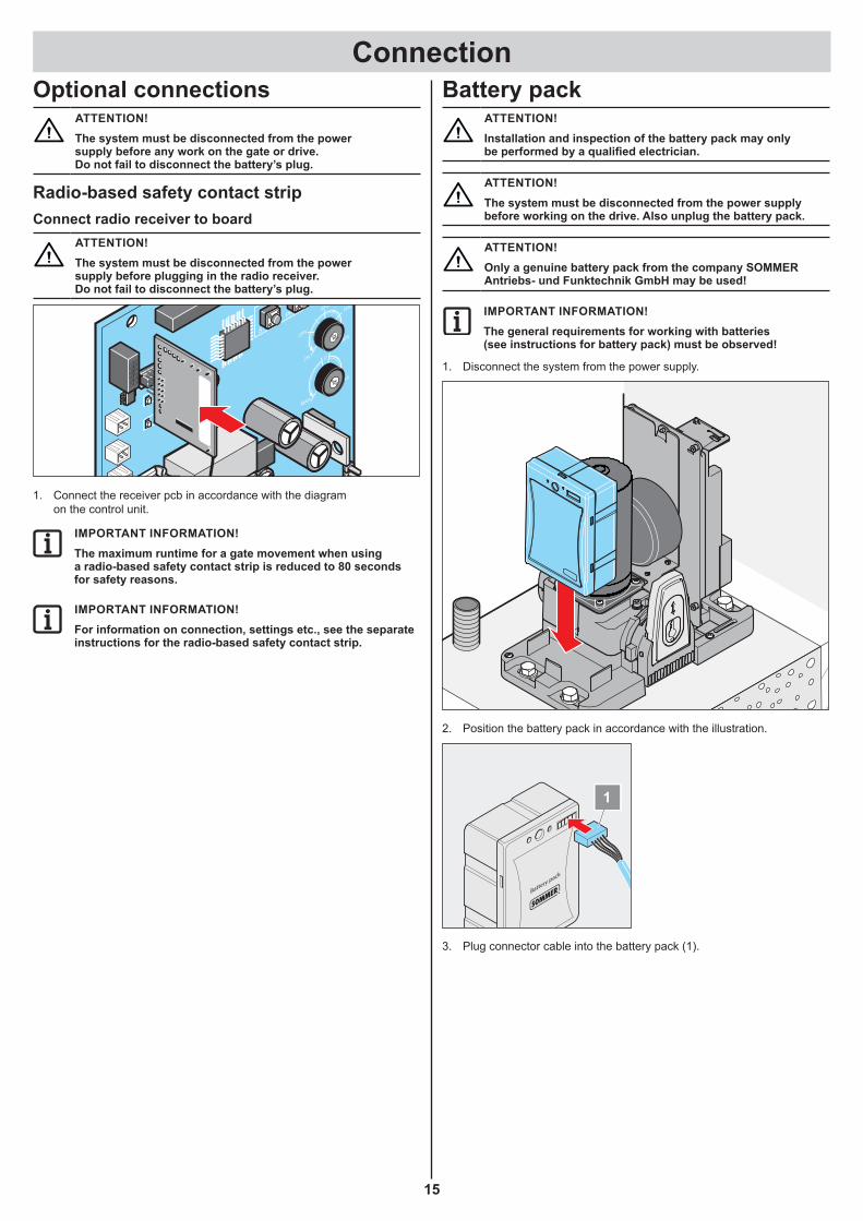
Optional connectionsATTENTION!The system must be disconnected from the power supply before any work on the gate or drive. Do not fail to disconnect the battery’s plug.
Radio-based safety contact stripConnect radio receiver to board
ATTENTION!The system must be disconnected from the power supply before plugging in the radio receiver. Do not fail to disconnect the battery’s plug.
8
TR
L1 L N N
10 12 14 16 18
79 11 13 15 17
20 22 24 26 28 30
19 21 23 25 27 29
100%START
PROG 75%50%
25%
0%
MAX
MAX
0
Limit
Limit
Stat
usSa
fety Li
ght
Rel
ay
1
ON
ECE
2 3 4 5 6 7 8
1. Connect the receiver pcb in accordance with the diagram on the control unit.
IMPORTANT INFORMATION!The maximum runtime for a gate movement when using a radio-based safety contact strip is reduced to 80 seconds for safety reasons.
IMPORTANT INFORMATION!For information on connection, settings etc., see the separate instructions for the radio-based safety contact strip.
Battery packATTENTION!Installation and inspection of the battery pack may only be performed by a qualified electrician.
ATTENTION!The system must be disconnected from the power supply before working on the drive. Also unplug the battery pack.
ATTENTION!Only a genuine battery pack from the company SOMMER Antriebs- und Funktechnik GmbH may be used!
IMPORTANT INFORMATION!The general requirements for working with batteries (see instructions for battery pack) must be observed!
1. Disconnect the system from the power supply.
2. Position the battery pack in accordance with the illustration.
Battery pack
4 1618
2022
2426
2830
1921
2325
2729
1
2
3. Plug connector cable into the battery pack (1).
Connection
16
Battery pack
4 1618
2022
2426
2830
1921
2325
2729
1
2
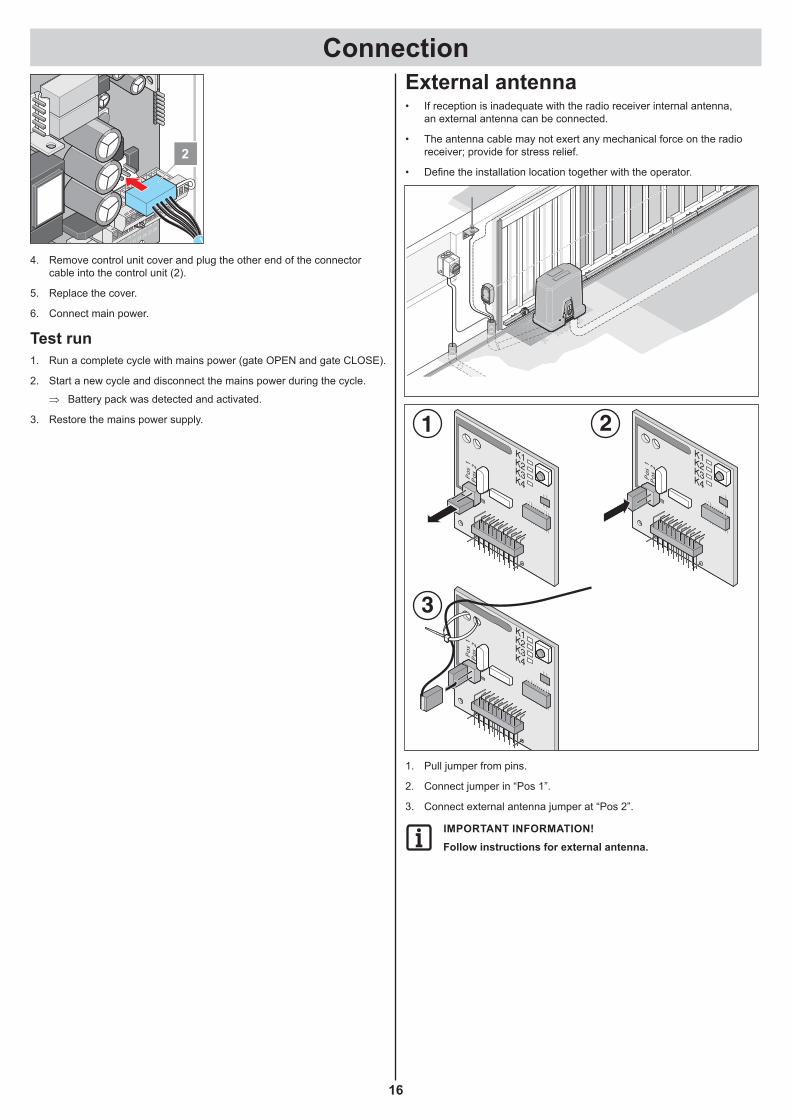
4. Remove control unit cover and plug the other end of the connector cable into the control unit (2).
5. Replace the cover.
6. Connect main power.
Test run1. Run a complete cycle with mains power (gate OPEN and gate CLOSE).
2. Start a new cycle and disconnect the mains power during the cycle.
⇒ Battery pack was detected and activated.
3. Restore the mains power supply.
External antenna• If reception is inadequate with the radio receiver internal antenna,
an external antenna can be connected.
• The antenna cable may not exert any mechanical force on the radio receiver; provide for stress relief.
• Define the installation location together with the operator.
SOMMERTORANTRIEBE
01
2
MCP
E
MCS
O
9
2 x 0,75 mm²
1
2
8
4 x 0,75 mm²
3
2 x 0,75 mm²
7
Pos
1P
os 2
Pos
1P
os 2
Pos
1P
os 2
1. Pull jumper from pins.
2. Connect jumper in “Pos 1”.
3. Connect external antenna jumper at “Pos 2”.
IMPORTANT INFORMATION!Follow instructions for external antenna.
17
Initial operationSafety instructions
IMPORTANT INFORMATION!After installation of the drive the person responsible for installation of the drive must issue an EC Declaration of Conformity for the door system in accordance with Machinery Directive 2006/42/EC and attach the CE symbol and a type plate. This is also required for private installations and also if the drive is retrofitted to a manually operated gate. This documentation and the Installation and Operating Instructions are retained by the operator.
IMPORTANT INFORMATION!The commissioning sequence described below is important. Upon being switched all safety and accessory elements connected to the control unit are automatically detected by the control unit and are checked for correct functioning. If additional peripherals are connected at a later date, the control unit must be reset before the drive can be operated again.
Adjusting the gate weightATTENTION!The gate weight must be precisely adjusted. If the setting is not correct, the operating forces will be too high and the power shut-off will be too late. Severe injuries may result.
8
TR
L1 L N N
10 12 14 16 18
79 11 13 15 17
20 22 24 26 28 30
19 21 23 25 27 29
100%START
PROG 75%50%
25%
0%
MAX
MAX
0
Limit
Limit
Stat
usSa
fety Li
ght
Rel
ay
1
ON
ECE
2 3 4 5 6 7 8
10
12
11
14 13
Gate weight Setting600 kg 100 %
450 kg 75 %
300 kg 50 %
150 kg 25 %
Locking weight potentiometerIMPORTANT INFORMATION!(1) After adjusting the gate weight, DIP switch 3 must be set to ON immediately. This prevents the weight adjustment and other parameters important for safe operation of the system from being accidentally changed.
1
ON
ECE
2 3 4 5 6 7 8
Connecting the power supplyConnect the power supply of your drive.
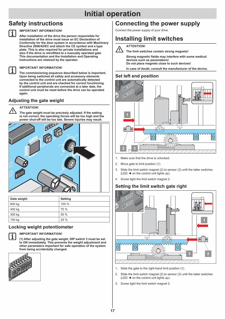
Installing limit switchesATTENTION!The limit switches contain strong magnets!Strong magnetic fields may interfere with some medical devices such as pacemakers! Do not place magnets close to such devices!In case of doubt, consult the manufacturer of the device.
Set left end position
1
32
Limit
Limit
1. Make sure that the drive is unlocked.
2. Move gate to limit position (1).
3. Slide the limit switch magnet (2) to sensor (3) until the latter switches (LED ◄ on the control unit lights up).
4. Screw tight the limit switch magnet 2.
Setting the limit switch gate right
1
3 2
Limit
Limit
1. Slide the gate to the right-hand limit position (1).
2. Slide the limit switch magnet (2) to sensor (3) until the latter switches (LED ◄ on the control unit lights up).
3. Screw tight the limit switch magnet 2.
Initial operation
18
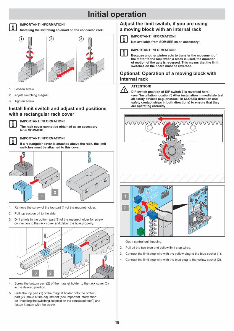
IMPORTANT INFORMATION!Installing the switching solenoid on the concealed rack.
321
1. Loosen screw.
2. Adjust switching magnet.
3. Tighten screw.
Install limit switch and adjust end positions with a rectangular rack cover
IMPORTANT INFORMATION!The rack cover cannot be obtained as an accessory from SOMMER!
IMPORTANT INFORMATION!If a rectangular cover is attached above the rack, the limit switches must be attached to this cover.
12
1. Remove the screw of the top part (1) of the magnet holder.
2. Pull top section off to the side.
3. Drill a hole in the bottom part (2) of the magnet holder for screw connection to the rack cover and debur the hole properly.
3 2
4. Screw the bottom part (2) of the magnet holder to the rack cover (3) in the desired position.
5. Slide the top part (1) of the magnet holder onto the bottom part (2), make a fine adjustment (see important information on “Installing the switching solenoid on the concealed rack”) and fasten it again with the screw.
Adjust the limit switch, if you are using a moving block with an internal rack
IMPORTANT INFORMATION!Not available from SOMMER as an accessory!
IMPORTANT INFORMATION!Because another pinion acts to transfer the movement of the motor to the rack when a block is used, the direction of motion of the gate is reversed. This means that the limit switches on the board must be reversed.
Optional: Operation of a moving block with internal rack
ATTENTION!DIP switch position of DIP switch 7 is reversed here! (see “Installation location”) After installation immediately test all safety devices (e.g. photocell in CLOSED direction and safety contact strips in both directions) to ensure that they are operating correctly!
Limit
LimitR
L
ER
8
TR
L1 L N N
10 12 14 16 18
79 11 13 15 17
20 22 24 26 28 30
19 21 23 25 27 29
100%START
PROG 75%50%
25%
0%
MAX
MAX
0
Limit
Limit
Stat
usSa
fety Li
ght
Rel
ay
1
ON
ECE
2 3 4 5 6 7 8
2
1
1. Open control unit housing.
2. Pull off the two blue and yellow limit stop wires.
3. Connect the limit stop wire with the yellow plug to the blue socket (1).
4. Connect the limit stop wire with the blue plug to the yellow socket (2).

Initial operation
19
Locking drive
1.
3.2.
1. Flip the locking lever upwards.
2. Close the lock.
3. Close the dust cap.
IMPORTANT INFORMATION!Move gate back and forth by hand so the pinion meshes with the rack more easily and the motor can lock.
⇒ Drive is locked and the gate can only be moved with the motor.
Resetting the control unit ⇒ Power must be connected.
8
TR
L1 L N N
10 12 14 16 18
79 11 13 15 17
20 22 24 26 28 30
19 21 23 25 27 29
100%START
PROG 75%50%
25%
0%
MAX
MAX
0
Limit
Limit
Stat
usSa
fety Li
ght
Rel
ay
1
ON
ECE
2 3 4 5 6 7 8
10
12
11
14 13
1. Press and hold down the “Start” and “Prog” buttons at the same time.
⇒ The “Light” LED starts flashing.
2. Release the buttons when the “Light” LED lights continuously.
⇒ Reset successfully completed.
IMPORTANT INFORMATION!A reset can take place only if the drive is locked!
Teach-in runIMPORTANT INFORMATION!Once programming has been started, it cannot be interrupted and restarted at a later time. If programming is interrupted, it must be restarted from the beginning.The “Light” LED flashes continuously during programming runs (as a rule 3 complete runs from one limit position to the other). The “Light” LED remains steady if the gate remains stationary between cycles.On completion of programming the LED switches off.
8
TR
L1 L N N
10 12 14 16 18
7 9 11 13 15 17
20 22 24 26 28 30
19 21 23 25 27 29
100%START
PROG 75%50%
25%
0%
MAX
MAX
0
Limit
Limit
Stat
usSa
fety Li
ght
Rel
ay
1
ON
ECE
2 3 4 5 6 7 8
STARTPROG 50%
25%
Stat
usSa
fety Li
ght
Rel
ay
1
ON
2 3
Ligh
t
10
12
11
14 13
1. Move gate manually to centre position.
2. Briefly press the start button on the control unit or the control device.
⇒ Move in initial position in automatic mode at reduced speed to the “Gate OPEN” limit position.
3. Briefly press the start button again on the control unit or the control device.
⇒ First programming run for path measurement in automatic mode at reduced speed to the “Gate CLOSED” limit position.
4. Briefly press the start button again on the control unit or the control device.
⇒ Second programming run for force measurement in automatic mode at standard speed including soft running ramps to the “Gate OPEN” limit position.
5. Briefly press the start button again on the control unit or the control device.
⇒ Third programming run for force measurement in automatic mode at standard speed including soft running ramps to the “Gate OPEN” limit position.
▫ When the “Light” LED goes out, ⇒ programming is complete.
▫ If the “Light” LED remains on, ⇒ repeat the procedure until the LED is out.
IMPORTANT INFORMATION!If a programming run is interrupted by an obstacle (operator stops and reverses), the programming procedure must be continued in deadman operation. This means that the start button on the control unit must be pressed and held down until the (above described) programming runs are completed. Do not press and release the start button as in automatic mode!
Checking the force toleranceCAUTION!Rubber safety strips must be used on the main and auxiliary closing edges. No sliding gate without safety strips may be used!
⇒ Our program contains various safety strips, both active (triggers an immediate stop of the gate at contact) and passive (takes up part of the inertial mass of the moving gate).
See also the section “Maintenance and care/Regular testing” on the subject of safety edges.
Test run1. Close the gate.
2. Press button (1) once. Gate opens to gate OPEN limit position.
3. Press button (1) once. The door closes up to the limit position door CLOSED.
4. If one of the set gate limit positions is not reached (gate OPEN or CLOSED), check whether the correct gate weight is set at the potentiometer.
⇒ Correct if necessary.

Initial operation
20
Radio receiver (version Somloq Rollingcode)Safety instructions
¾ The local safety regulations for the system must be complied with to ensure safe operation! Information is available from electrical utility companies, VDE (Association for Electrical, Electronic & Information Technologies) and professional associations.
¾ The operator is not protected against interference caused by other telecommunications equipment or devices (e.g. wireless systems which are being operated properly in the same frequency range).
¾ Replace the handheld transmitter unit’s batteries if you experience reception problems.
ATTENTION!The radio receiver must be connected or disconnected from the control unit only if the control unit is disconnected from the power supply. If the drive is operated by battery, it must also be disconnected from the control unit.
1
2.1
2.2
2.32.4
1. Learn button
2.1 LED channel 1
2.2 LED channel 2
2.3 LED channel 3
2.4 LED channel 4
Explanation of radio channelsChannel 1 Pulse mode
Channel 2 Active leaf
Channel 3 Defined OPEN
Channel 4 Defined CLOSE or pot.-free relay (must be activated by TorMinal)
Pulse sequence of gate movementsRadio channel 1: OPEN – STOP – CLOSE – STOP – OPEN – STOP – CLOSE…
Radio channel 2: Partial opening
Radio channel 3: OPEN – STOP – OPEN – STOP – OPEN…
Radio channel 4: CLOSE – STOP – CLOSE – STOP – CLOSE…
IMPORTANT INFORMATION!Delete the memory of the radio receiver before the first teach-in of handheld transmitters.
Deleting the radio receiver memory1. Press and hold the learn button (1).
⇒ After 5 seconds one of the LEDs flashes – after another 10 seconds another LED lights.
⇒ After a total of 25 seconds all LEDs light.
2. Release the learn button (1).
⇒ The deletion procedure is ended.
Deleting a channel from the radio receiver1. Press and hold the learn button (1).
▫ 1x for channel 1; the LED (2.1) lights up. ▫ 2x for channel 2; the LED (2.2) lights up. ▫ 3x for channel 3; the LED (2.3) lights up. ▫ 4x for channel 4; the LED (2.4) lights up.
⇒ The LED flashes after 5 seconds.
⇒ The LED lights after another 10 seconds
2. Release the teach-in button (1).
⇒ The deletion procedure is ended.
Programming the handheld remote controlCAUTION!The radio remote control may only be used if the door’s movement can be watched and no persons or objects are within the range of movement.
IMPORTANT INFORMATION!Delete the memory of the radio receiver before the first teach-in of handheld transmitters.
8
TR
L1 L N N
10 12 14 16 18
79 11 13 15 17
20 22 24 26 28 30
19 21 23 25 27 29
100%START
PROG 75%50%
25%
0%
MAX
MAX
0
Limit
Limit
Stat
usSa
fety Li
ght
Rel
a y
1
ON
ECE
2 3 4 5 6 7 8
1. Press the learn button.
▫ 1x for channel 1; the LED (2.1) lights up. ▫ 2x for channel 2; the LED (2.2) lights up. ▫ 3x for channel 3; the LED (2.3) lights up. ▫ 4x for channel 4; the LED (2.4) lights up.
⇒ If no code is sent within 10 seconds, the radio receiver switches to Normal mode.
2. Press the desired hand-held transmitter button until the LED (2.1/2.2/ 2.3/2.4) goes out, depending which channel has been selected.
⇒ LED goes out – programming is finished.
⇒ The handheld transmitter has transferred the radio code to the radio transmitter.
3. Repeat the above steps to program by teach-in any additional handheld transmitters. A maximum of 112 storage locations for each radio receiver are available.
Cancelling the programming modePress the learn button (1) until all LEDs are out or make no input for 10 seconds.
Initial operation
21
Deleting the handheld transmitter from the radio receiverIf a handheld transmitter is to be deleted from the radio receiver, every button and every short cut of the handheld transmitter must be deleted for security reasons!
1. Press the teach-in button (1) and keep it pressed for 5 seconds.
⇒ One of the LEDs flashes.
2. Release the teach-in button (1).
⇒ The radio receiver is in Deletion mode.
3. Press the transmitter button whose code should be deleted in the radio receiver.
⇒ The LED goes out. The deletion procedure is ended.
4. Repeat the procedure for all buttons and shortcuts.
Teach-in by radio (HFL)Prerequisites for teach-in by radioAt least one handheld transmitter has been programmed by teach-in via the radio receiver (see Teach-in of handheld receivers).
RestrictionsThe following is not possible by radio:
• The targeted teach-in of a selected handheld transmitter button on a radio channel.
• Deletion of a handheld transmitter, radio channel or of the entire radio receiver (memory).
• Changing the programming of a handheld transmitter programmed by teach-in by radio (e.g. teach-in of another button).
Importation information• Each handheld transmitter that has already been programmed
by teach-in can put the radio receiver into teach-in mode by radio.• Radio receivers that are within the range of the handheld transmitter
are put into teach-in mode simultaneously.• The key assignment of handheld transmitter (A) that put the radio
receiver into teach-in mode by radio is used for the new handheld transmitter (B) that is to be programmed by teach-in. Example: Button 1 on channel 1 and button 2 on channel 2 has been programmed by teach-in by handheld transmitter (A).
⇒ The new handheld transmitter (B) that has been programmed by teach-in has acquired the key assignment of handheld transmitter (A): Button 1 on channel 1 and button 2 on channel 2.
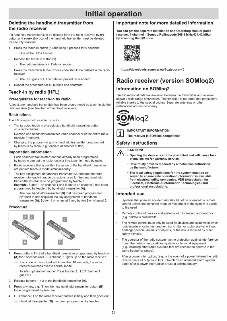
Procedure
A B
1 32
1. Press buttons 1 + 2 of a handheld transmitter programmed by teach-in (A) for 5 seconds until LED channel 1 lights up on the radio receiver.
⇒ If no code is transmitted within another 10 seconds, the radio receiver switches over to normal mode.
⇒ To interrupt teach-in mode: Press button (1), LED channel 1 goes out.
2. Release buttons 1 + 2 of the handheld transmitter (A).
3. Press any key, e.g. (3) on the new handheld transmitter button (B) to be programmed by teach-in.
4. LED channel 1 on the radio receiver flashes initially and then goes out
⇒ Handheld transmitter (B) has been programmed by teach-in.
Important note for more detailed informationYou can get the separate Installation and Operating Manual (radio receiver, 4-channel – Somloq Rollingcode/868.8 MHz/434,42 MHz) by scanning the QR code.
https://downloads.sommer.eu/?category=40
Radio receiver (version SOMloq2)Information on SOMloq2The bidirectional data transmission between the transmitter and receiver allows a wide range of functions. Transmission is tap-proof and particularly reliable thanks to the special coding. Separate antennas or other installations are not necessary.
IMPORTANT INFORMATION!The receiver is SOMlink-compatible!
Safety instructionsCAUTION!• Opening the device is strictly prohibited and will cause loss
of any claims for warranty service.• Have faulty devices repaired by a technician authorised
by the manufacturer.• The local safety regulations for the system must be ob-
served to ensure safe operation! Information is available from electrical utility companies, VDE (Association for Electrical, Electronic & Information Technologies) and professional associations.
Intended use• Systems that pose an accident risk should not be operated by remote
control unless the complete range of movement of the system is visible to the user!
• Remote control of devices and systems with increased accident risk (e.g. hoists) is prohibited!
• The remote control must only be used for devices and systems in which radio interference in the handheld transmitter or radio receiver will not endanger people, animals or objects, or the risk is reduced by other safety devices.
• The operator of the radio system has no protection against interference from other telecommunications systems or terminal equipment (e.g. including other radio systems that are licensed to operate in the same frequency range).
• After a power interruption, (e.g. in the event of a power failure), he radio receiver sets all outputs to OFF. Switch on an actuated alarm system again after a power interruption or use a backup battery.
Initial operation
22
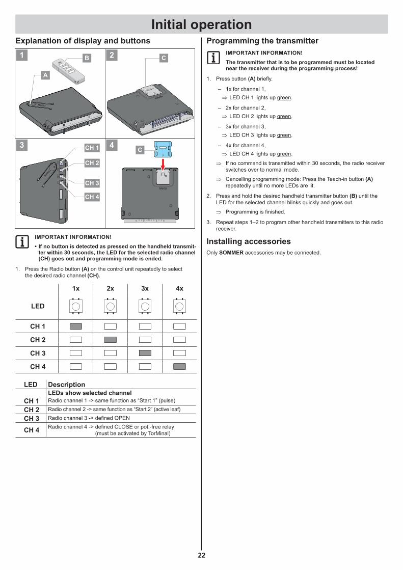
Explanation of display and buttons
Radio
CH
1C
H2
CH
3C
H4
Radio
CH 1
CH 2
CH 4
CH 3
C
A
B
C
1 2
3 4
IMPORTANT INFORMATION!• If no button is detected as pressed on the handheld transmit-
ter within 30 seconds, the LED for the selected radio channel (CH) goes out and programming mode is ended.
1. Press the Radio button (A) on the control unit repeatedly to select the desired radio channel (CH).
1x 2x 3x 4x
LED
CH 1
CH 2
CH 3
CH 4
LED DescriptionLEDs show selected channel
CH 1 Radio channel 1 -> same function as “Start 1” (pulse)
CH 2 Radio channel 2 -> same function as “Start 2” (active leaf)
CH 3 Radio channel 3 -> defined OPEN
CH 4 Radio channel 4 -> defined CLOSE or pot.-free relay (must be activated by TorMinal)
Programming the transmitterIMPORTANT INFORMATION!The transmitter that is to be programmed must be located near the receiver during the programming process!
1. Press button (A) briefly.
– 1x for channel 1, ⇒ LED CH 1 lights up green.
– 2x for channel 2, ⇒ LED CH 2 lights up green.
– 3x for channel 3, ⇒ LED CH 3 lights up green.
– 4x for channel 4, ⇒ LED CH 4 lights up green.
⇒ If no command is transmitted within 30 seconds, the radio receiver switches over to normal mode.
⇒ Cancelling programming mode: Press the Teach-in button (A) repeatedly until no more LEDs are lit.
2. Press and hold the desired handheld transmitter button (B) until the LED for the selected channel blinks quickly and goes out.
⇒ Programming is finished.
3. Repeat steps 1–2 to program other handheld transmitters to this radio receiver.
Installing accessoriesOnly SOMMER accessories may be connected.

Initial operation
23
Programming by radio (HFL)FunctionEach handheld transmitter that has already been programmed can put the receiver into programming mode by radio. This allows additional transmitters to be programmed without having to press button (A) on the receiver. The button assignment on handheld transmitter A (Fig. HFL) (which activated the receiver) is also used for handheld transmitter (B) which needs to be programmed. Both handheld transmitters must be located within the range of the radio receiver.
Inverted fast flashes (HFL)
IMPORTANT INFORMATION!Only the programming of identical handheld transmitters by radio is recommended!If different handheld transmitter types are used, only the first button command is transferred from handheld transmitter 1 toImportant information!handheld transmitter 2.
Procedure1. Press and hold buttons (1+2) of the previously programmed handheld
transmitter A for 3–5 seconds until LEDs (CH 1 and CH 2) on the receiver fast flash inverted green.
2. Release buttons (1+2).
⇒ If a command is not transmitted within another 30 seconds, the radio receiver switches over to normal mode.
3. Press any button on the new handheld transmitter B.
⇒ LEDs (CH 1–CH 4) on the receiver blink quickly and go out.
⇒ Commands and key assignment on handheld transmitter B and handheld transmitter A are now identical.
Operation1. Press transmitter button (B) briefly.
⇒ LED for the programmed channel lights up orange as long as the button is pressed.
⇒ The assigned output switches.
Deleting a transmitter button from the radio channel1. Select radio channel with button (A) and hold the button pressed for
15 to 20 seconds until the LED for the selected channel flashes red.
2. Release Teach-in button (A). ⇒ To cancel delete mode: Press button (A); LED goes out.
⇒ If no command is transmitted within 30 seconds, the radio receiver switches over to normal mode.
3. On the transmitter, press the button for which the command is to be deleted in the radio receiver.
⇒ LED blinks quickly – delete complete.
⇒ Radio receiver switches to normal mode – delete complete.
Deleting a transmitter from the radio receiver1. Press and hold button (A) for 20 to 25 seconds until LED (CH 1)
blinks red.
2. Release button (A). ⇒ To cancel delete mode: Press button (A); LED (CH 1) goes out.
⇒ If no command is transmitted within 30 seconds, the radio receiver switches over to normal mode.
3. Press any button on the transmitter that is to be deleted from the receiver memory.
⇒ Radio receiver deletes the transmitter, LED (CH 1) blinks quickly.
⇒ Radio receiver switches to normal mode – delete complete.
Deleting a radio channelIMPORTANT INFORMATION!This action cannot be interrupted!
1. Select the radio channel to be deleted with button (A) and hold button (A) pressed for 25–30 seconds until the LED for the selected channel lights up red.
2. Release button (A). ⇒ The channel is deleted from the radio receiver.
⇒ Receiver switches to normal mode – delete complete.
Deleting the entire memory of the radio receiver
IMPORTANT INFORMATION!This action cannot be interrupted!
If a transmitter is lost, all channels in the radio receiver must be deleted for security reasons! Then reprogramme all transmitters.
1. Press and hold button (A) for more than 30 seconds until the LEDs (CH 1–CH 4) simultaneously light up red.
2. Release button (B). ⇒ Radio receiver deletes the memory.
⇒ Radio receiver switches to normal mode – delete complete.
If the memory capacity has been reachedA total of 40 handheld transmitter commands are available for all channels. If an attempt is made to program additional transmitters, the red LEDs of radio channels CH 1–4 blink.
Information on MemoThe memory capacity can be extended to 450 handheld transmitter com-mands using the optional Memo accessory part. When the Memo is plugged in, all available transmitters are transferred from the internal memory to the Memo and stored there. The Memo must remain plugged in on the control unit. No more transmitters are then stored in the internal memory. Stored transmitters cannot be transferred from the Memo back to the internal memory. All radio channels, including the memo-ry of the Memo, can be deleted.
Installing the MemoCAUTION!If the Memo is removed, the receiver memory is empty. Radio commands need to be programmed again!
1. Turn off the power supply to the operator control unit.
2. Disconnect the receiver from the operator control unit.
3. Plug the Memo (C) into the slot.
4. Reconnect the receiver to the operator control unit.
5. Restore the power supply.
⇒ A total of 450 memory positions is now available for radio commands.
Important note for more detailed informationYou can get the separate Installation and Operating Manual (radio receiver SOMup4 – SOMloq2/868.95 MHz) by scanning the QR code.
https://downloads.sommer.eu/?category=36

Initial operation
24
Concluding commissioningATTENTION!The power supply cord must be routed complete with its sheathing into the enclosure!
12
1. Remove the power supply cord provided and replace it with a permanently installed power supply cable.
IMPORTANT INFORMATION!In order to maintain the functionality of the technical equip-ment, we recommend that you observe the specified maximum lengths and minimum cross-sections for power cables!Connection lines Signal linesMaximum length 20 m Maximum length 25 mMinimum cross-section 1.5 mm²Approved wire cross sections for all terminals: 1 mm²–2.5 mm².
2. Attach the hood.
3. Fasten the hood with the screw.
IMPORTANT INFORMATION!To prevent the ingress of water, the wiper must be located behind the cover, as shown.
25
OperationSafety instructions
¾ The radio remote control may only be used if the door’s movement can be watched and no persons or objects are within the range of movement.
¾ Keep children, disabled persons and animals away from the gate. ¾ Never reach into a moving gate or moving parts. ¾ Dot not drive through the gate until it has been fully opened. ¾ Entrapment and/or cutting hazard from the mechanism or closing
edges of the gate. ⇒ The safety instructions in this manual and the applicable standards
and directives for securing closing edges must be observed at all times.
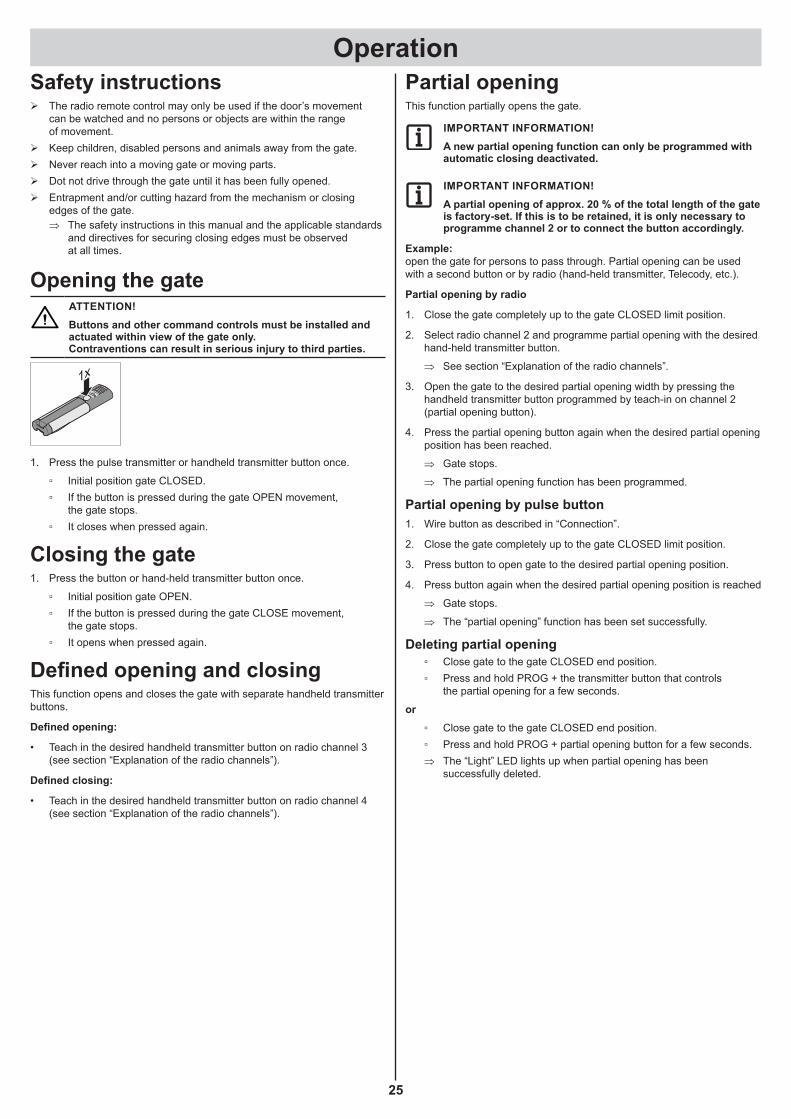
Opening the gateATTENTION!Buttons and other command controls must be installed and actuated within view of the gate only. Contraventions can result in serious injury to third parties.
1x
1. Press the pulse transmitter or handheld transmitter button once.
▫ Initial position gate CLOSED. ▫ If the button is pressed during the gate OPEN movement,
the gate stops. ▫ It closes when pressed again.
Closing the gate1. Press the button or hand-held transmitter button once.
▫ Initial position gate OPEN. ▫ If the button is pressed during the gate CLOSE movement,
the gate stops. ▫ It opens when pressed again.
Defined opening and closingThis function opens and closes the gate with separate handheld transmitter buttons.
Defined opening:
• Teach in the desired handheld transmitter button on radio channel 3 (see section “Explanation of the radio channels”).
Defined closing:
• Teach in the desired handheld transmitter button on radio channel 4 (see section “Explanation of the radio channels”).
Partial openingThis function partially opens the gate.
IMPORTANT INFORMATION!A new partial opening function can only be programmed with automatic closing deactivated.
IMPORTANT INFORMATION!A partial opening of approx. 20 % of the total length of the gate is factory-set. If this is to be retained, it is only necessary to programme channel 2 or to connect the button accordingly.
Example: open the gate for persons to pass through. Partial opening can be used with a second button or by radio (hand-held transmitter, Telecody, etc.).
Partial opening by radio
1. Close the gate completely up to the gate CLOSED limit position.
2. Select radio channel 2 and programme partial opening with the desired hand-held transmitter button.
⇒ See section “Explanation of the radio channels”.
3. Open the gate to the desired partial opening width by pressing the handheld transmitter button programmed by teach-in on channel 2 (partial opening button).
4. Press the partial opening button again when the desired partial opening position has been reached.
⇒ Gate stops.
⇒ The partial opening function has been programmed.
Partial opening by pulse button1. Wire button as described in “Connection”.
2. Close the gate completely up to the gate CLOSED limit position.
3. Press button to open gate to the desired partial opening position.
4. Press button again when the desired partial opening position is reached
⇒ Gate stops.
⇒ The “partial opening” function has been set successfully.
Deleting partial opening ▫ Close gate to the gate CLOSED end position. ▫ Press and hold PROG + the transmitter button that controls
the partial opening for a few seconds.
or ▫ Close gate to the gate CLOSED end position. ▫ Press and hold PROG + partial opening button for a few seconds.
⇒ The “Light” LED lights up when partial opening has been successfully deleted.
Operation
26
Automatic closing functionATTENTION!Risk of injury during automatic closing. Automatically closing gates can injure people who are in the movement area of the gate when the gate is closing. Always install a photocell before activating the function! This is a legal requirement.
ATTENTION!The control unit does not respond to continuous signals in the gate OPEN direction.
IMPORTANT INFORMATION!A timer can be set up only using TorMinal. See the separate TorMinal instructions.When the timer is connected, the partial opening can be used by radio again.
IMPORTANT INFORMATION!Operation with automatic closing must comply with EN 12453.
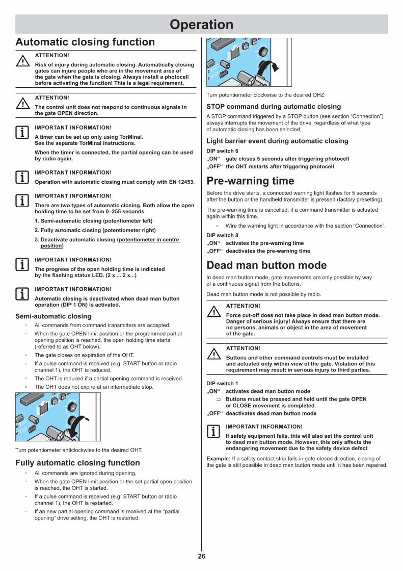
IMPORTANT INFORMATION!There are two types of automatic closing. Both allow the open holding time to be set from 0–255 seconds1. Semi-automatic closing (potentiometer left)2. Fully automatic closing (potentiometer right)3. Deactivate automatic closing (potentiometer in centre
position)
IMPORTANT INFORMATION!The progress of the open holding time is indicated by the flashing status LED. (2 x ... 2 x...)
IMPORTANT INFORMATION!Automatic closing is deactivated when dead man button operation (DIP 1 ON) is activated.
Semi-automatic closing ▫ All commands from command transmitters are accepted. ▫ When the gate OPEN limit position or the programmed partial
opening position is reached, the open holding time starts (referred to as OHT below).
▫ The gate closes on expiration of the OHT. ▫ If a pulse command is received (e.g. START button or radio
channel 1), the OHT is reduced. ▫ The OHT is reduced if a partial opening command is received. ▫ The OHT does not expire at an intermediate stop.
8
TR
L1 L N N
10 12 14 16 18
79 11 13 15 17
20 22 24 26 28 30
19 21 23 25 27 29
100%START
PROG 75%50%
25%
0%
MAX
MAX
0
Limit
Limit
Stat
usSa
fety Li
ght
Rel
ay
1
ON
ECE
2 3 4 5 6 7 8
10
12
11
14 13
Turn potentiometer anticlockwise to the desired OHT.
Fully automatic closing function ▫ All commands are ignored during opening. ▫ When the gate OPEN limit position or the set partial open position
is reached, the OHT is started. ▫ If a pulse command is received (e.g. START button or radio
channel 1), the OHT is restarted. ▫ If an new partial opening command is received at the “partial
opening” drive setting, the OHT is restarted.
8
TR
L1 L N N
10 12 14 16 18
79 11 13 15 17
20 22 24 26 28 30
19 21 23 25 27 29
100%START
PROG 75%50%
25%
0%
MAX
MAX
0
Limit
Limit
Stat
usSa
fety Li
ght
Rel
ay
1
ON
ECE
2 3 4 5 6 7 8
10
12
11
14 13
Turn potentiometer clockwise to the desired OHZ.
STOP command during automatic closingA STOP command triggered by a STOP button (see section “Connection”) always interrupts the movement of the drive, regardless of what type of automatic closing has been selected.
Light barrier event during automatic closingDIP switch 6„ON“ gate closes 5 seconds after triggering photocell„OFF“ the OHT restarts after triggering photocell
Pre-warning timeBefore the drive starts, a connected warning light flashes for 5 seconds after the button or the handheld transmitter is pressed (factory presetting).
The pre-warning time is cancelled, if a command transmitter is actuated again within this time.
▫ Wire the warning light in accordance with the section “Connection”.
DIP switch 8„ON“ activates the pre-warning time„OFF“ deactivates the pre-warning time
Dead man button modeIn dead man button mode, gate movements are only possible by way of a continuous signal from the buttons.
Dead man button mode is not possible by radio.
ATTENTION!Force cut-off does not take place in dead man button mode. Danger of serious injury! Always ensure that there are no persons, animals or object in the area of movement of the gate.
ATTENTION!Buttons and other command controls must be installed and actuated only within view of the gate. Violation of this requirement may result in serious injury to third parties.
DIP switch 1„ON“ activates dead man button mode
⇒ Buttons must be pressed and held until the gate OPEN or CLOSE movement is completed.
„OFF“ deactivates dead man button mode
IMPORTANT INFORMATION!If safety equipment fails, this will also set the control unit to dead man button mode. However, this only affects the endangering movement due to the safety device defect
Example: If a safety contact strip fails in gate-closed direction, closing of the gate is still possible in dead man button mode until it has been repaired.
Operation
27
Obstruction detectionATTENTION!Buttons and other command controls must be installed and actuated only within view of the gate. Violation of this requirement may result in serious injury to third parties.
ATTENTION!The reversing length must be set as short as possible to prevent an additional danger source being caused at an auxiliary closing edge on gates with trellis bars. The reversing times can be changed with the TorMinal.
IMPORTANT INFORMATION!Reversing: The drive stops when it meets an obstruction and then moves in the opposite direction to release the obstruction.Partial reversing: The drive reverses by a predefined distance to release the encountered obstruction.Full reversing: The drive reverses completely back to the limit position.
The following safety devices are installed to detect obstacles:
▫ Photocell (object protection). ▫ Safety contact strips (personal protection). ▫ Force cut-off of drive (personal protection).
Obstacle detection by photocellATTENTION!A photocell must be used for object protection only. A photocell must not be used for personal protection!
▫ Wire the light barrier in accordance with the section “Connection”.
Behaviour in gate CLOSEDIP 4„ON“ Full reversing„OFF“ Partial reversing
IMPORTANT INFORMATION!A photocell has no effect in the gate OPEN direction!
IMPORTANT INFORMATION!If the photocell is interrupted, the gate runs on for a short distance!
Obstacle detection by safety contact strips ▫ Connect safety contact strips as described in “Connection”.
ATTENTION!Make absolutely sure that the safety contact strips are connected for the correct direction (OPEN/CLOSE). A safety contact strip connected for gate CLOSE will not respond in the gate OPEN direction and vice versa.
BehaviourDIP 2„ON“ Full reversing„OFF“ Partial reversing
Force cut-off of operatorATTENTION!There is no force cut-off in dead man button mode. This operating mode is activated by default during the programming phase. It is also activated if DIP switch 1 is set to ON. There is a risk of serious injury for anyone in the range of movement of the gate in this operating mode!
▫ The sensitivity of the force cut-off depends on the correct weight setting of the gate or the weight potentiometer.
⇒ See section Commissioning on this subject.
Power-saving modeTo save energy, the drive control unit switches to power-saving mode after the specified period. Connected accessories (e.g. photocell, safety contact strip, external radio receiver etc.) are deactivated and then reactivated at the next command (button, radio etc.).
IMPORTANT INFORMATION!The factory-set period before the control unit switches to power-saving mode is 6.5 minutes. The period can be changed with a TorMinal. (see TorMinal instructions)
Important information when using an external radio receiverBecause external radio receivers are deactivated in power-saving mode, they cannot receive commands from the hand-held remote control when the control unit has switched to power-saving mode.
If an external radio receiver is used, power-saving mode must be deactivated with DIP switch 5.
Deactivating power-saving modeDIP 5„ON“ Power-saving mode deactivated„OFF“ power-saving activated (factory setting)
Important information when using a battery packIf there is a power failure, the control unit automatically switches to power-saving mode after 5 seconds in order to extend the battery life.
If a battery pack is connected, standby mode is automatically deactivated to enable charging of the battery pack.
Overload protectionIf the operator is overloaded during opening or closing, the control unit detects this and stops the drive.
A control unit reset then puts the operator back in standby mode (See section ‘Commissioning’).
Operation after a power failureIf there is a power failure while a battery pack is connected, the control unit automatically switches to power-saving mode after 5 seconds in order to extend the battery life. This function cannot be deactivated.
The programmed force values and the end positions are stored in the event of a power failure. The first movement of the operator after a power failure is always door OPEN.
If the power failure occurs during a door movement, the operator stops. The operator can be restarted with a command device when the power supply has been restored. The operator then moves in automatic mode at reduced speed to “Door OPEN” end position.

Operation
28
Emergency releaseATTENTION!During an emergency release the gate may start moving autonomously, if it is not aligned so that it is perfectly horizontal. Risk of injury!
IMPORTANT INFORMATION!A photocell has no effect in the gate OPEN direction!
IMPORTANT INFORMATION!It can be released in any gate position.If the operator is not locked at a limit position and restarted by a control device after an emergency release, it moves in automatic mode at reduced speed to the “Gate OPEN” limit position.If this movement is interrupted by an obstacle, the operator stops and reverses. It can be restarted with a control device. The next movement is in automatic mode the “Gate CLOSED” limit position.
Releasing the drive
2.1.
3.
1. Open dust cap.
2. Unlock lock.
3. Flip the locking lever downwards.
⇒ The drive is released. The gate can now be moved by hand only.
Locking drive
1.
3.2.
1. Flip the locking lever upwards.
2. Close the lock.
3. Close the dust cap.
IMPORTANT INFORMATION!Move gate back and forth by hand so the pinion meshes with the rack more easily and the motor can lock.
⇒ Drive is locked and the gate can only be moved with the motor.

Additional connection options
29
Maintenance and careSafety instructions
DANGER!Never use a water hose or high-pressure cleaner to spray down the operator or the control unit housing.
¾ Before any work on the gate or drive disconnect it from the power supply and lock it to prevent reconnection.
¾ Do not use acids or alkalis for cleaning. ¾ Wipe the operator clean with a dry cloth as required. ¾ Never reach into a moving gate or moving parts. ¾ Crush and shear hazards at the closing edges and the mechanical
systems of the gate. ¾ Check that all fastening screws and bolts of the operator are tight and
retighten them where necessary. ¾ Check the gate in accordance with the manufacturer’s instructions.
Regular testingSafety devices must be tested at intervals which do not exceed six months and which must be prescribed in the maintenance instructions for the door, in accordance with EN 12453-1/2.
Check every 4 weeks that pressure-sensitive safety devices (e. g. safety contact strips) are operating correctly, in accordance with EN 60335-2-103.
Testing Behaviour yes or no Possible cause RemedyForce cut-offStop gate during clos-ing with an object 50 mm x 50 mm.
Does drive reverse when it contacts the object?
Yes • The power deactivation is functioning.
No • Force tolerance too high. • Reduce the force tolerance with TorMinal until the test is successful. First open and close the gate completely twice under supervision. See TorMinal owner’s manual.
• Gate incorrectly adjusted • Adjust the gate, call a technician!
Emergency releaseProceed as described in the “Emergency release” section.
The gate must be easily opened and closed by hand. (Gate is balanced)
Yes • Everything is OK!
No • Emergency release defective.
• Repair emergency release.
• Gate jams. • Check the gate, see maintenance instructions for the gate.
Safety contact strip, if presentOpen and close the gate and actuate the strip at the same time.
Behaviour of the gate as set via DIP switch 2.Safety LED lights continu-ously.
Yes • Everything is OK!
No • Cable breakage, terminal loose.
• Check the wiring; retighten the terminals.
• Strip defective. • Decommission the gate and lock it to prevent reactivation. Call customer service!
Photo relay, if presentOpen and close the door while interrupting the photocell
Behaviour of the gate as set via DIP switch 4.Safety LED lights continu-ously.
Yes • Everything is OK!
No • Cable breakage, terminal loose.
• Check the wiring; retighten the terminals.
• Light barrier dirty. • Clean the light barrier.
• Light barrier incorrectly adjusted (holder bent)
• Adjust light barriers.
• Photo relay fault. • Decommission the gate and lock it to prevent reactivation. Call customer service!

30
TroubleshootingMalfunction Possible cause Corrective actionDrive does not close the gate. • Light barrier power supply interrupted. Check connection
Replace fuse.
• Drive has been disconnected from mains power supply.
• The drive always opens the gate completely upon first command after the power supply has been restored.
• The drive was in an intermediate position when it was disconnected from the mains supply or emergency released and as a consequence has switched over to dead man button operation.
• Move gate to a limit position in dead man button mode and lock it in this position.
Operator opens the gate and then does not respond to a command from the remote control.
• Safety input triggered (e.g. light barrier defective), safety LED flashing (see table).
• Remove object from light barrier.• Repair photocells.• Control unit not properly plugged in.
Speed varies during opening and closing. • Drive starts and slows down before reaching the limit position.
Completely normal, drive starts at maximum speed. The drive reduces speed before reaching the other limit position (soft running).
Gate cannot be operated unless the user press-es and holds the buttons, e.g. key switches.
• Dead man button mode switched on. Deactivate dead man button mode, see section “Select DIP switch settings” or “Remedy defec-tive safety periphery”.
Only radio receiver!All LEDs flashing. • All memory locations occupied, max. 112. • Delete any transmitters that are no longer
needed.• Install additional radio receivers.
One of the LEDs on the receiver is on continu-ously.
• The radio signal is being received; the button of a handheld remote control may be defective or an external signal present.
• Remove the battery from the handheld transmitter.
• Wait until the external signal falls off.
One of the LEDs on the receiver is on. • The radio receiver is in the teach-in mode and awaiting a radio code from a handheld remote control.
Press the desired handheld transmitter button.
Description of the flash sequences of the LEDs
8
TR
L1L
NN
1012
1416
18
79 11
1315
17
2022
2426
2830
1921
2325
2729
100%STA
RTPRO
G75%50%
25%
0%
MAX
MAX
0
Limit
Limit
Status
Safety Ligh
tRe
lay
1
ON
ECE
2 3 4 5 6 7 8
8
9
10
12
1115
18
19
14 13
543
16
17
20Flash sequences of the safety LED Meaning Continuously on Emergency release is actuated, EMERGENCY STOP or stop button
is pressed.
.......... 2x Safety contact strip is bent or power has been deactivated
.......... 3x Photocell is interrupted.
.......... 4x Runtime is >90 seconds, path is too short or too long.
.......... 5x System error: control unit has a defect or is overloaded.
.......... 1x Battery charge is no longer sufficient.
Flash sequences of the status LED Meaning Continuously on System OK.
4x Power-saving mode is activated.
.......... 2x Open time of auto closing is expiring.
...3 sec... ...3 sec... ...3 sec... 1x Operator is in power-saving mode.

Disassembly and disposal
31
Disassembly and disposalDisassembly
IMPORTANT!Observe the safety notices!
The sequence is identical to that described in the “Installation” section, but in reverse order. Ignore the setting instructions.
DisposalObserve applicable national regulations!
Warranty and customer serviceThe warranty complies with statutory requirements. The contact person for warranties is the specialist retailer. The warranty is only valid in the country in which the drive was purchased.
Batteries, fuses and bulbs are excluded from the warranty.
If you require after-sales service, spare parts or accessories, please contact your specialist retailer.
We have tried to make the Installation and Operating Instructions as easy as possible to follow. If you have any suggestions as to how we could improve them or if you think more information is needed, please send your suggestions to us:
+49 (0) 7021 8001-401
DIP switch settings
Switch ON OFF (delivery status)1 Deadman operation activated. Deadman button mode deactivated.
2 Reaction to SKL input/force cut-offFull reversing Partial reversing
3 Weight potentiometer blocked. Weight potentiometer unblocked.
4 Reaction to light barrier when closingFull reversing Partial reversing
5 Power-saving modePower-saving mode deactivated Power-saving mode activated
6 Gate closes 5 seconds after triggering light barrier.
Triggering light barrier resets the open holding time.
7 Gate right stop. Gate left stop.
8 Early warning time activated. Early warning time deactivated.

Troubleshooting
32
Connection diagram
7
8
9
10
11
12
13
14
15
16
17
18
19
20
21
22 24
23
26
25
28
27
30
29
Warning light DC 24 V
Partial opening button / timer
Emergency STOP pushbutton
Photo eye 4-wire
Floa
ting
rela
y co
ntac
t/m
ax. D
C/AC
24
V; 1
A
0V GN
D
GN
D
Pulse button
STO
P
STOP button
OPE
N
CLO
SE
PULS
E
NC
COM
Photo eye 2-wire
+20
V; 4
00 m
A
GN
D
PART
IAL
OPE
NIN
G
Sign
al
Sign
al
SKL
"OPE
N" G
ND
SKL
"OPE
N" S
igna
l
SKL
"OPE
N" +
12 V
SKL
"CLO
SE" +
12 V
SKL
"CLO
SE" S
igna
l
SKL
"CLO
SE" G
ND
GNDGND
+12 V+12 Vsignalsignal
GNDGND
BrownBrown BrownBrown
WhiteWhite WhiteWhite
FR 1FR 1
+12V
+12V
Gre
enG
reen
Gre
enG
reen
GNDGND
+12 V+12 Vsignalsignal
GNDGND
BrownBrown BrownBrown
WhiteWhite WhiteWhite
FR 1FR 1
+12V
+12V
Gre
enG
reen
Gre
enG
reen
Option: 8.2 KΩ safety edge 8.2 KΩ
Option: Optoelectronic SKLOption: Optoelectronic SKL
Gate CLOSE button
Gate OPEN button
Power supply 4-wire
If several 8.2 KΩ edges are wired in series, only one resistor can still be used
If several 8.2 KΩ edges are wired in series, only one resistor can still be used
8,2 KΩ Strip 1Strip 2Strip 3
Strip 1 Strip 2 Strip 3
Option: 8.2 KΩ safety edge 8.2 KΩ
8,2 KΩ


SOMMER Antriebs- und Funktechnik GmbH
Hans-Böckler-Straße 27 73230 Kirchheim/Teck Germany
+49 (0) 7021 8001-0
+49 (0) 7021 8001-100
[email protected] www.sommer.eu
© Copyright 2021 All rights reserved.