sliding mode control based on fractional order calculus...
TRANSCRIPT
International Journal of
Mathematical Modelling & Computations
Vol. 05, No. 04, Fall 2015, 319- 333
Sliding Mode Control based On Fractional order Calculus for
DC-DC Converters
N. Bouarroudj a,b,∗ , D. Boukhetalab , B. Benlahbiba and B. Batoun a
aUnite de Recherche Appliquee en Energies Renouvelables, URAER, Centre de
Developpement des Energies Renouvelables, CDER, 47133, Ghardaia, Algeria;bLCP, departement d’automatique, Ecole Nationale Polytechnique, 10 av. Hassen Badi,
BP. 182, El-Harrach, Alger, Algeria.
Abstract.The aim of this paper is to design a Fractional Order Sliding Mode Controllers(FOSMC) for a class of DC-DC converters such as boost and buck converters. Firstly, thecontrol law is designed with respect to the properties of fractional calculus, the design yieldsan equivalent control term with an addition of discontinuous (attractive) control law. Sec-ondly, the mathematical proof of the stability condition and convergence of the proposedfractional order sliding surface is presented. Finally the effectiveness and robustness of theproposed approaches compared with classical SMCs are demonstrated by simulation resultswith different cases.
Received: 20 May 2015, Revised: 29 August 2015, Accepted: 12 October 2015.
Keywords: DC-DC Buck converter, DC-DC Boost converter, Fractional order calculus,FOSMC.
Index to information contained in this paper
1 Introduction
2 Basic Definitions of Fractional Calculus
3 DC-DC Converters
4 Fractional order Sliding Mode Controller (FOSMC) Design
5 Simulation Results
6 Conclusion
1. Introduction
Since the middle of the 20th century, DC-DC converters have gained an increasingplace in industrial applications, especially in the field of power electronics. Theseconverters are electronic circuits which convert a voltage from one level to a higheror lower one. Among these converters we have the Buck and Boost converter.
∗Corresponding author. Email: n [email protected] or [email protected]
c⃝ 2015 IAUCTBhttp://www.ijm2c.ir
320 N. Bouarroudj et al./ IJM2C, 05 - 04 (2015) 319-333.
Many works are reported for the regulation of the output voltage of these con-verters in the closed loop, such as the Proportional Integral (PI) and hystereticcontrol....etc.Besides, the Sliding Mode Control (SMC) for example was largely proved its
efficiency through the reported theoretical studies [1], [2], [3], [4]. The first stepof SMC design is to select a sliding surface that models the desired closed-loopperformance in state variable space. The second step is to design the equivalentand a hitting control law such as the system state trajectories forced toward thesliding surface and slides along it to the desired attitude.Many works based on sliding mode are reported in integer order control of DC-
DC converters [5], [6], [7], [8] before the apparition of the fractional order slidingmode control by [9], [10] and [11]; these fractional controllers are based on thefractional order PI, PD and PID sliding surfaces.Motivated by the above discussion this paper designs a Fractional Order Sliding
Mode Controller (FOSMC) for buck and boost converters in which the slidingsurface proposed for the buck converter is a generalization of the classical PDsliding surface S = e + λe , where the integer order derivative of error will be of
fractional order (D(α−1)t e, 0 ≺ α ≺ 1) and the term (λ.e ) will be (λ.eP , 0<P<1)
(see [12]).With these two added parameters ( α and P) we can say that, the performance
of the system can be improved.For boost converter, the proposed fractional order sliding surface exploits the
advantages of the fractional integrator that are fast convergence and precision, inwhich the integer order sliding surface S= λ.e [8] will be S = λD−α
t e, 0 ≺ α ≺ 1.The rest of this article is organized as follows. Basic Definitions of Fractional
Calculus in section II. DC-DC converters in section III. The fractional order slid-ing mode controller design in section IV. And finally the simulation results andconclusion are given in Sections V and VI, respectively.
2. Basic Definitions of Fractional Calculus
The fractional differo-integral operators denoted by aDαt f(t) (where a and t are
the bounds of the operation) are a generalization of integration and differentiationof the operators of a non integer order. In the literature we find different definitionsof fractional differo-integral, but the commonly used are:The Riemann-Liouville (RL) definition:
aDαt f(t) =
1
Γ(m− α)
(d
dt
)m ∫ t
a
f(τ)
(t− τ)1−(m−α)dτ (1)
The Caputo’s definition:
aDαt f(t) =
1
Γ(m− α)
∫ t
a
fm(τ)
(t− τ)1−(m−α)dτ (2)
Where m-1<α<m and Γ(.) is the well-known Euler’s gamma function, and itsdefinition is:
Γ(x) =
∫ ∞
0e−tt(x−1)dt, x > 0 (3)
N. Bouarroudj et al./ IJM2C, 05 - 04 (2015) 319-333. 321
On the other hand, Grunwald-Letnikov (GL) reformulated the definition of thefractional order differ-integral as follows:
aDαt f(t) = hlim−→0
1
hα
(t−a)/h∑k=0
(−1)k(αk
)f(t− kh) (4)
Because the numerical simulation of a fractional differential equation is not sim-ple as that of an ordinary differential equation [21], [22], so the Laplace transformmethod is often used as being a tool for the resolution of the problems arising inengineering [13], [14].In the following, we give the Laplace transforms of the fractional order derivative
given previously.The Laplace transform of (RL) definition is as follows [13], [15]:
L 0Dαt f(t); s = sαF (s)−
(m−1)∑k=0
sk[0D
(α−k−1)t f(t)
]t=0
(5)
The Laplace transform of Caputo’s definition is given by [15]:
L 0Dαt f(t); s = sαF (s)−
(m−1)∑k=0
s(α−k−1)fk(0) (6)
Where s = jw denotes the Laplace operator. For zero initial conditions, theLaplace transform of fractional derivative of Riemann-Liouville, Caputo andGrunwald-Letnikov reduced to (7) [15], [16].
L (0Dαt f(t)) = sαF (s) (7)
In this paper the fractional order element sα is approximated with Oustaloup’sfilter. The Oustaloup’s filter [17] is based on the approximation of a function of theform:
G(s) = sα, α ∈ R+ (8)
By a rational function:
G(s) = K′
N′∏
k=−N ′
s+ w′
k
s+ wk(9)
Where the parameters of this function (zeros, poles, and gain) can be determinedby the following formulas:
322 N. Bouarroudj et al./ IJM2C, 05 - 04 (2015) 319-333.
w′
k = wb.(wh/wb
)(k+N′+0.5(1−α))/(2N
′+1)
w′
k = wb.(wh/wb
)(k+N′+0.5(1+α))/(2N
′+1)
K = wαh
(10)
(2N’+1) is the order of the filter, wb and wh are respectively the Low and Hightransient-frequencies.The following properties of Caputo’s definition are used in this paper:Fractional order derivative of fractional integration of a function f (t) [15]:
Dαt
(D−α
t f(t))= f(t) (11)
Fractional integration of fractional order derivative of a function f (t) [15]:
D−αt (Dα
t f(t)) = f(t)− f(0) for 0 < α < 1 (12)
3. DC-DC Converters
The DC/DC converters are electronic circuits allow to generate a continuous andvariable source of tension from a continuous and fixed source of tension.In general case these converters consist of a switch (Sw) with control input u
between 0 and 1, a fast diode D and R, L, C components.For the controller design, it is necessary to give the mathematical model of these
converters, which can be obtained by applying the two Kirchhoff’s laws (currentand voltage).
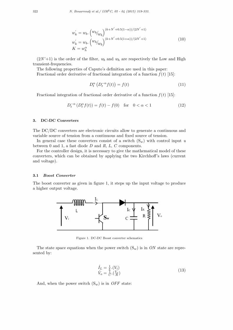
3.1 Boost Converter
The boost converter as given in figure 1, it steps up the input voltage to producea higher output voltage.
Figure 1. DC-DC Boost converter schematics
The state space equations when the power switch (Sw) is in ON state are repre-sented by:
IL = 1L .(Vi)
Vo =1C .(
Vo
R )(13)
And, when the power switch (Sw) is in OFF state:

N. Bouarroudj et al./ IJM2C, 05 - 04 (2015) 319-333. 323
IL = 1L .(Vi − Vo)
Vo =1C .(IL − Vo
R )(14)
The selection of the output voltage (V o) and inductor current (IL) as statevariables of the system, such as:
x1 = ILx2 = Vo
(15)
Leads to state space model describing the system as the following:
x1 =(Vi−x2)
L + x2
L .ux2 =
1C (x1 −
x2
R )− x1
C .u(16)
Where the two equations below are considered for simplification of calculations:
f1(x) =(Vi−x2)
L , b1(x) =(x2)L
f2(x) =1C (x1 −
x2
R ), b2(x) =−(x1)C
3.2 Buck Converter
The buck converter as shown in figure 2, is a voltage step down and current stepup converter.
Figure 2. DC-DC Buck converter schematics
When the ideal switch (Sw) is in ON state, the dynamics of the inductor currentIL(t) and the output voltage V o(t) are given by:
IL = 1L .(Vi − Vo)
Vo =1C .(IL − Vo
R )(17)
And when the switch (Sw)isinOFFstate :
IL = 1L .(Vo)
Vo =1C .(IL − Vo
R )(18)
Selecting the output voltage (Vo) and its derivative (dVo/dt) as system statevariables, that is:
324 N. Bouarroudj et al./ IJM2C, 05 - 04 (2015) 319-333.
x1 = Vo
x2 = Vo(19)
Leads to the state space model describing the system, derived as:
x1 = x2x2 = − x1
LC − x2
RC + Vi
LCu(20)
For the controller design we set the following simplification:f1(x) = − x1
LC − x2
RC and b1(x) =Vi
LC
4. Fractional order Sliding Mode Controller (FOSMC) Design
The sliding mode control strategy is divided into three steps such as:
(1) Selection of sliding surface: it is usually designed to full fill the desiredcontrol objectives.
(2) Calculation of the controller u(t) which is given by the following equa-tion :
u(t) = ueq(t) + un(t) (21)
Where ueq is the equivalent control law that is derived by setting S(t) = 0, un is called the discontinuous (or attractive) control low.
(3) Stability analysis: For the stability analysis, the candidate Lyapunovfunction given below is considered:
V =1
2S2 (22)
We say the system is stable when we have:
V = SS ≤ 0 (23)
4.1 FOSMC for Boost Converter
For the boost converter presented by equation (16), we propose the following slidingsurface based on fractional order integrator as follows:
S(t) = λD−αt e(t) (24)
Where e(t) = x1(t)− x1d(t), λ is positive constant, and 0 ≺ α ≺ 1Remark: it is clear that selecting α = 0 the classical sliding surfaces S(t) = λe(t)
can be recovered [7].The desired current (x 1) is obtained from the outer voltage loop as followings
[7]:
N. Bouarroudj et al./ IJM2C, 05 - 04 (2015) 319-333. 325
x1d =V 2o
R.Vi(25)
Differentiating both sides of (24) to the order unity yields the equality in (26):
S(t) = λD−αt e(t)
= λD−αt (x1(t)− x1d(t))
= λD−αt (f
1(x) + b1(x).u− x1d(t))
(26)
By setting S(t) = 0 the equivalent control is obtained, and it has the owingformula:
ueq(t) =−1
b1(x)(f
1(x)− x1d(t)) (27)
Then, the global control is given by:
u(t) =−1
b1(x)(f
1(x)− x1d(t) +K.Dα
t (sgn(S))) (28)
Where:
sgn(S) =
−1 if S ≺ 00 if S = 01 if S ≻ 0
(29)
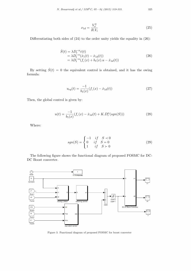
The following figure shows the functional diagram of proposed FOSMC for DC-DC Boost converter.
Figure 3. Functional diagram of proposed FOSMC for boost converter
326 N. Bouarroudj et al./ IJM2C, 05 - 04 (2015) 319-333.
For the stability analysis, substituting of (28) in (26) results:
S(t) = −λ.K.(sgn(S(t)))− λ.K.(sgn(S(0))) (30)
For initial condition x 1(0) =0, the sliding surface S at t=0 is 0, then equation (30)can be rewritten as the following:
S(t) = −λ.K.(sgn(S(t))) (31)
Using equation (23):
SS = −λ.K.S.(sgn(S))= λ.K. |S| ≤ 0 (32)
As conclusion, the proposed sliding surface can satisfy the stability condition; onthe other hand the sgn function can causes the chattering phenomenon; and toavoid this problem we replace the sgn function by a saturation (sat) one; and thecontrol signal u(t) will be:
u(t) =−1
b1(x)(f
1(x)− x1d(t) +K.Dα
t (sat(S))) (33)
where:
sat(ϕ) =
ϕ if |ϕ| < 1sgn(ϕ) if |ϕ| ≥ 1
(34)
4.2 FOSMC for Buck Converter
For the Buck converter presented by (20), firstly we define the following fractionalorder sliding surface using Caputo’s definition as:
S = D(α−1)t e+ λeP (35)
This proposed sliding surface is somewhat similar to [12], it has the potentialto improve the control performance, because extra real parameters α and P areinvolved.Where e = x 1-x 1d, λ is positive constant, and 0<α, P<1.
Remark: It is clear that selecting α=P=1, the classical sliding surface S = e+λecan be recovered.
Differentiating both sides of (35) to the order unity yields the equality in (36);
S = D(α−1)t (x1 − x1d) + λP (e(P−1)e) (36)
The expression of the equivalent control is easily derived by setting S = 0 as:
ueq =−1
b1(x)
[f1(x)− x1d + λ.P.D
(1−α)t (e(P−1).e)
](37)
N. Bouarroudj et al./ IJM2C, 05 - 04 (2015) 319-333. 327
The switching or attractive control unis generally equal to (-K sign(S )). But a largecontrol gain K often causes the chattering effect. In order to tackle this problem,several method of SMC with reaching law, were designed [18], [19]. In this paperwe chose the one of [20] given by the following equation of integer order:
un = −Ksign(S)− ρS (38)
Because the controller is of fractional order, this structure will be modified (seebelow) to satisfy the stability condition.Then, the global fractional order sliding mode controller u will be:
u = −1b(x)
[f(x)− x1d + λ.P.D
(1−α)t (e(P−1).e)...
+D(1−α)t (Ksgn(S) + ρ.S)
] (39)
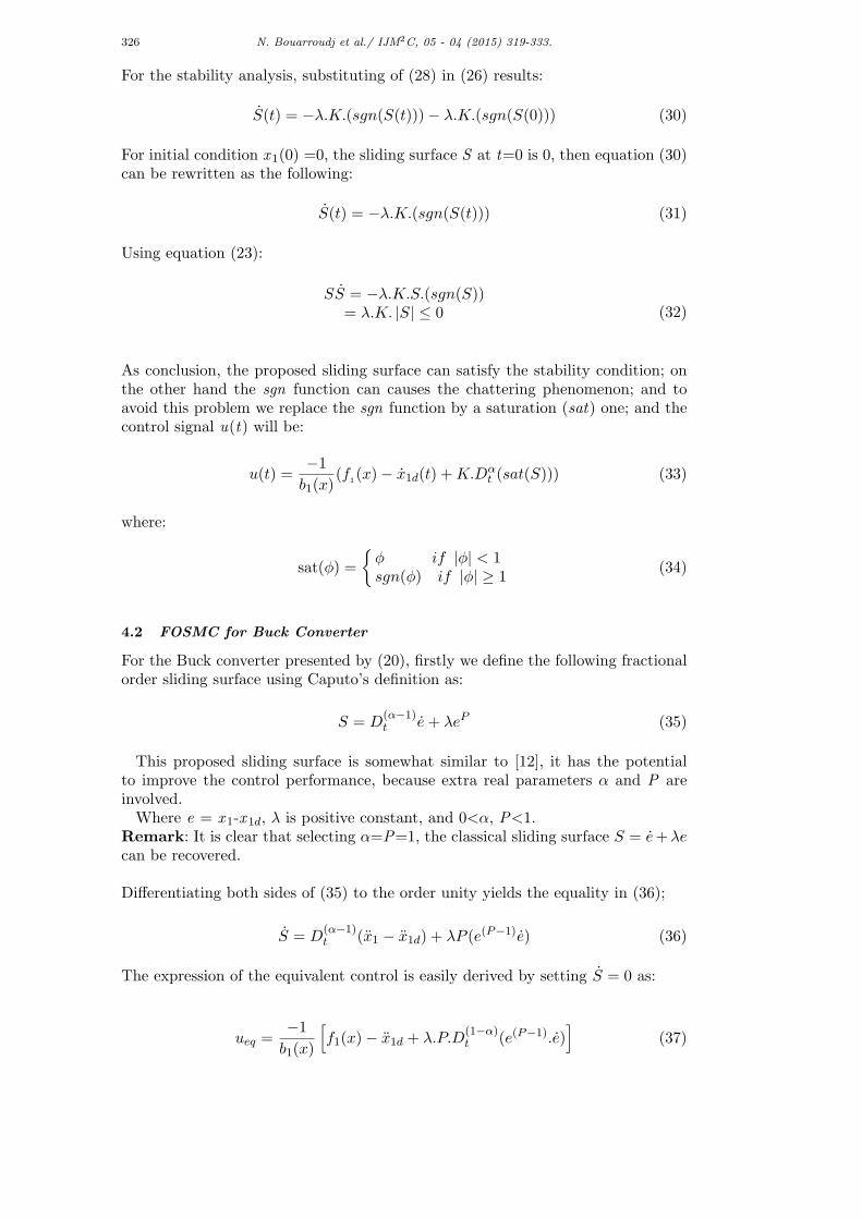
The following figure summarizes the developed controller for DC-DC buck con-verter.
Figure 4. Functional diagram of proposed FOSMC for buck converter
Substituting (39) into (36), and taking into account the properties in (11) and (12),results in:
SS = S[−λ.P.e(P−1)(0).e(0)− (Ksgn(S) + ρ.S)
−(K.sgn(S(0)) + ρ.S(0))](40)
If one assume that:−λ.P.e(P−1)(0).e(0)− (K.sgn(S(0)) + ρ.S(0)) = 0 then simply:
SS = S [−(Ksgn(S) + ρ.S)]= −K |S| − ρ.S2 ≤ 0
(41)
Otherwise, if:
328 N. Bouarroudj et al./ IJM2C, 05 - 04 (2015) 319-333.
λ.P.e(P−1)(0).e(0) + (K.sgn(S(0)) + ρ.S(0)) ≤ ζ (42)
This lets us have:
SS = S [−(Ksgn(S) + ρ.S)− ζ]= −(K + ζ) |S| − ρ.S2 ≤ 0
(43)
In summary; the proposed fractional order sliding surface can guarantee the sta-bility condition.
5. Simulation Results
5.1 For Boost Converter
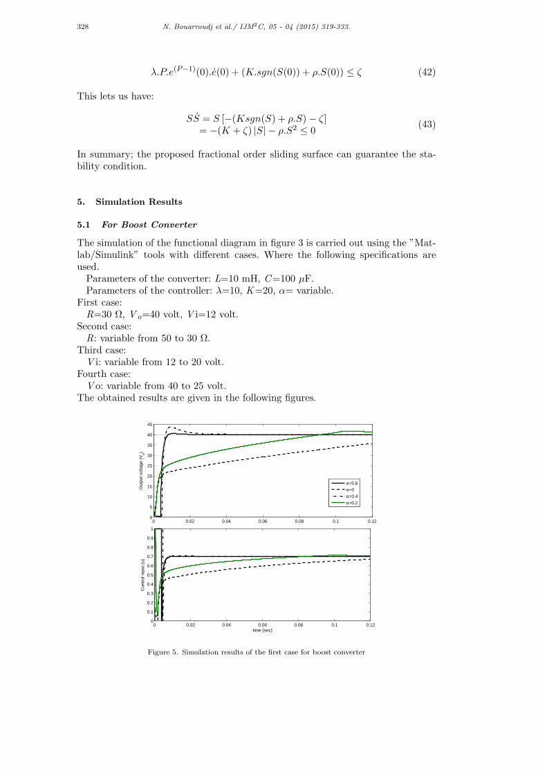
The simulation of the functional diagram in figure 3 is carried out using the ”Mat-lab/Simulink” tools with different cases. Where the following specifications areused.Parameters of the converter: L=10 mH, C=100 µF.Parameters of the controller: λ=10, K=20, α= variable.
First case:R=30 Ω, V o=40 volt, V i=12 volt.
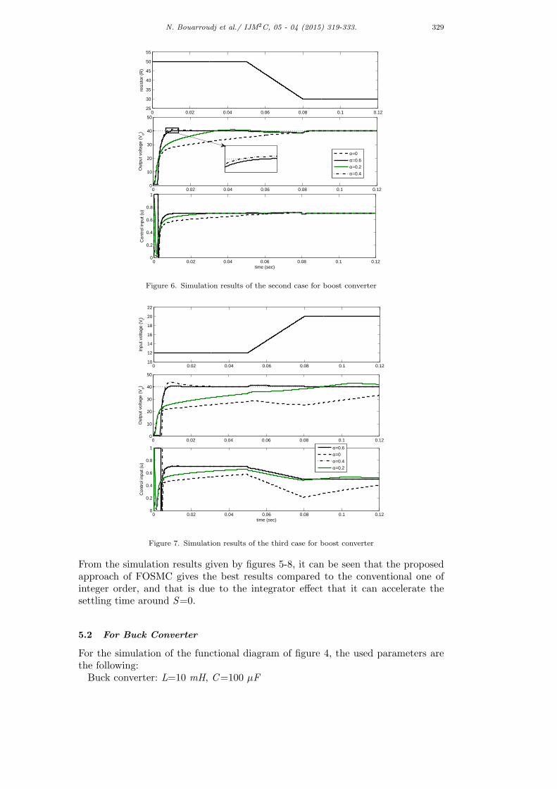
Second case:R: variable from 50 to 30 Ω.
Third case:V i: variable from 12 to 20 volt.
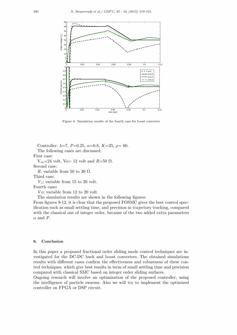
Fourth case:V o: variable from 40 to 25 volt.
The obtained results are given in the following figures.
0 0.02 0.04 0.06 0.08 0.1 0.120
5
10
15
20
25
30
35
40
45
Out
put v
olta
ge (
Vo)
0 0.02 0.04 0.06 0.08 0.1 0.120
0.1
0.2
0.3
0.4
0.5
0.6
0.7
0.8
0.9
1
time (sec)
Con
trol
inpu
t (u)
α=0.6
α=0
α=0.4
α=0.2
Figure 5. Simulation results of the first case for boost converter
N. Bouarroudj et al./ IJM2C, 05 - 04 (2015) 319-333. 329
0 0.02 0.04 0.06 0.08 0.1 0.1225
30
35
40
45
50
55
resi
stor
(R
)
0 0.02 0.04 0.06 0.08 0.1 0.120
10
20
30
40
50
Out
put v
olta
ge (
Vo)
0 0.02 0.04 0.06 0.08 0.1 0.120
0.2
0.4
0.6
0.8
1
time (sec)
Con
trol
inpu
t (u)
α=0
α=0.6
α=0.2
α=0.4
Figure 6. Simulation results of the second case for boost converter
0 0.02 0.04 0.06 0.08 0.1 0.1210
12
14
16
18
20
22
Inpu
t vol
tage
(V
i)
0 0.02 0.04 0.06 0.08 0.1 0.120
10
20
30
40
50
Out
put v
olta
ge (
Vo)
0 0.02 0.04 0.06 0.08 0.1 0.120
0.2
0.4
0.6
0.8
1
time (sec)
Con
trol
inpu
t (u)
α=0.6
α=0
α=0.4
α=0.2
Figure 7. Simulation results of the third case for boost converter
From the simulation results given by figures 5-8, it can be seen that the proposedapproach of FOSMC gives the best results compared to the conventional one ofinteger order, and that is due to the integrator effect that it can accelerate thesettling time around S=0.
5.2 For Buck Converter
For the simulation of the functional diagram of figure 4, the used parameters arethe following:Buck converter: L=10 mH, C=100 µF
330 N. Bouarroudj et al./ IJM2C, 05 - 04 (2015) 319-333.
0 0.02 0.04 0.06 0.08 0.1 0.120
5
10
15
20
25
30
35
40
45
Out
put v
olta
ge (
Vo)
0 0.02 0.04 0.06 0.08 0.1 0.120
0.1
0.2
0.3
0.4
0.5
0.6
0.7
0.8
0.9
1
time (sec)
Con
trol
inpu
t (u)
α=0
α=0.6
α=0.2
α=0.4
Figure 8. Simulation results of the fourth case for boost converter
Controller: λ=7, P=0.25, α=0.8, K=35, ρ= 60.The following cases are discussed:
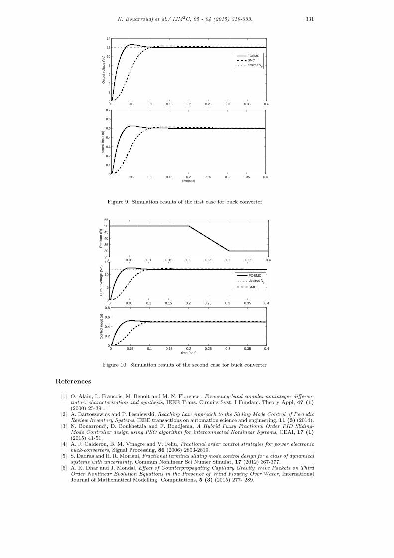
First case:Vin=24 volt, Vo= 12 volt and R=50 Ω.
Second case:R: variable from 50 to 30 Ω.
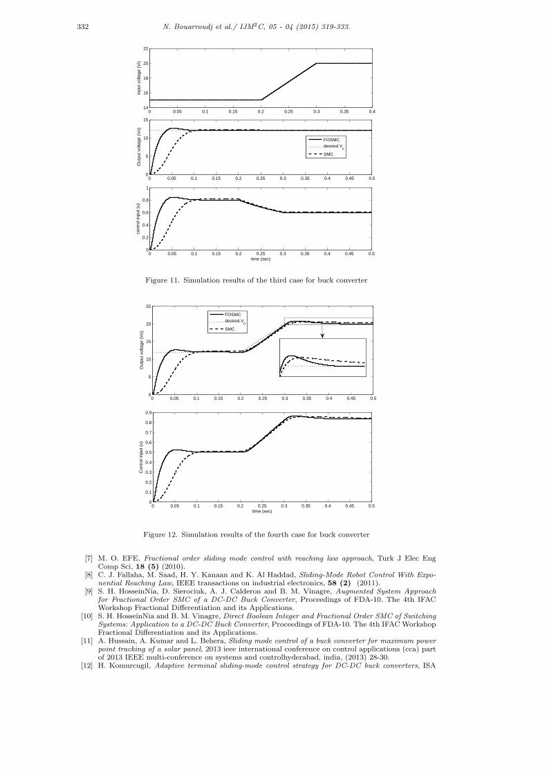
Third case:V i: variable from 15 to 20 volt.
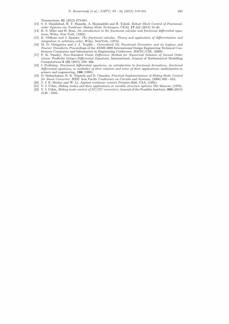
Fourth case:V o: variable from 12 to 20 volt.The simulation results are shown in the following figures:
From figures 9-12, it is clear that the proposed FOSMC gives the best control spec-ification such as small settling time, and precision in trajectory tracking, comparedwith the classical one of integer order, because of the two added extra parametersα and P.
6. Conclusion
In this paper a proposed fractional order sliding mode control techniques are in-vestigated for the DC-DC buck and boost converters. The obtained simulationsresults with different cases confirm the effectiveness and robustness of these con-trol techniques, which give best results in term of small settling time and precisioncompared with classical SMC based on integer order sliding surfaces.Ongoing research will involve an optimization of the proposed controller, usingthe intelligence of particle swarms. Also we will try to implement the optimizedcontroller on FPGA or DSP circuit.
N. Bouarroudj et al./ IJM2C, 05 - 04 (2015) 319-333. 331
0 0.05 0.1 0.15 0.2 0.25 0.3 0.35 0.40
2
4
6
8
10
12
14
Out
put v
olta
ge (
Vo)
0 0.05 0.1 0.15 0.2 0.25 0.3 0.35 0.40
0.1
0.2
0.3
0.4
0.5
0.6
0.7
time(sec)
cont
rol i
nput
(u)
FOSMCSMCdesired V
o
Figure 9. Simulation results of the first case for buck converter
0 0.05 0.1 0.15 0.2 0.25 0.3 0.35 0.425
30
35
40
45
50
55
Res
isto
r (R
)
0 0.05 0.1 0.15 0.2 0.25 0.3 0.35 0.40
5
10
15
Out
put v
olta
ge (
Vo)
0 0.05 0.1 0.15 0.2 0.25 0.3 0.35 0.40
0.2
0.4
0.6
0.8
time (sec)
Con
trol
inpu
t (u)
FOSMCdesired V
o
SMC
Figure 10. Simulation results of the second case for buck converter
References
[1] O. Alain, L. Francois, M. Benoit and M. N. Florence , Frequency-band complex noninteger differen-tiator: characterization and synthesis, IEEE Trans. Circuits Syst. I Fundam. Theory Appl, 47 (1)(2000) 25-39 .
[2] A. Bartoszewicz and P. Lesniewski, Reaching Law Approach to the Sliding Mode Control of PeriodicReview Inventory Systems, IEEE transactions on automation science and engineering, 11 (3) (2014).
[3] N. Bouarroudj, D. Boukhetala and F. Boudjema, A Hybrid Fuzzy Fractional Order PID Sliding-Mode Controller design using PSO algorithm for interconnected Nonlinear Systems, CEAI, 17 (1)(2015) 41-51.
[4] A. J. Calderon, B. M. Vinagre and V. Feliu, Fractional order control strategies for power electronicbuck-converters, Signal Processing, 86 (2006) 2803-2819.
[5] S. Dadras and H. R. Momeni, Fractional terminal sliding mode control design for a class of dynamicalsystems with uncertainty, Commun Nonlinear Sci Numer Simulat, 17 (2012) 367-377.
[6] A. K. Dhar and J. Mondal, Effect of Counterpropagating Capillary Gravity Wave Packets on ThirdOrder Nonlinear Evolution Equations in the Presence of Wind Flowing Over Water, InternationalJournal of Mathematical Modelling Computations, 5 (3) (2015) 277- 289.
332 N. Bouarroudj et al./ IJM2C, 05 - 04 (2015) 319-333.
0 0.05 0.1 0.15 0.2 0.25 0.3 0.35 0.414
16
18
20
22
Inpu
t vol
tage
(V
i)
0 0.05 0.1 0.15 0.2 0.25 0.3 0.35 0.4 0.45 0.50
5
10
15
Out
put v
olta
ge (
Vo)
0 0.05 0.1 0.15 0.2 0.25 0.3 0.35 0.4 0.45 0.50
0.2
0.4
0.6
0.8
1
time (sec)
cont
rol i
nput
(u)
FOSMCdesired V
o
SMC
Figure 11. Simulation results of the third case for buck converter
0 0.05 0.1 0.15 0.2 0.25 0.3 0.35 0.4 0.45 0.50
5
10
15
20
25
Out
put v
olta
ge (
Vo)
0 0.05 0.1 0.15 0.2 0.25 0.3 0.35 0.4 0.45 0.50
0.1
0.2
0.3
0.4
0.5
0.6
0.7
0.8
0.9
time (sec)
Con
trol
inpu
t (u)
FOSMCdesired V
o
SMC
Figure 12. Simulation results of the fourth case for buck converter
[7] M. O. EFE, Fractional order sliding mode control with reaching law approach, Turk J Elec EngComp Sci, 18 (5) (2010).
[8] C. J. Fallaha, M. Saad, H. Y. Kanaan and K. Al Haddad, Sliding-Mode Robot Control With Expo-nential Reaching Law, IEEE transactions on industrial electronics, 58 (2) (2011).
[9] S. H. HosseinNia, D. Sierociuk, A. J. Calderon and B. M. Vinagre, Augmented System Approachfor Fractional Order SMC of a DC-DC Buck Converter, Proceedings of FDA-10. The 4th IFACWorkshop Fractional Differentiation and its Applications.
[10] S. H. HosseinNia and B. M. Vinagre, Direct Boolean Integer and Fractional Order SMC of SwitchingSystems: Application to a DC-DC Buck Converter, Proceedings of FDA-10. The 4th IFAC WorkshopFractional Differentiation and its Applications.
[11] A. Hussain, A. Kumar and L. Behera, Sliding mode control of a buck converter for maximum powerpoint tracking of a solar panel, 2013 ieee international conference on control applications (cca) partof 2013 IEEE multi-conference on systems and controlhyderabad, india, (2013) 28-30.
[12] H. Komurcugil, Adaptive terminal sliding-mode control strategy for DC-DC buck converters, ISA
N. Bouarroudj et al./ IJM2C, 05 - 04 (2015) 319-333. 333
Transactions, 51 (2012) 673-681.[13] S. S. Majidabad, H. T. Shandiz, A. Hajizadehb and H. Tohidi, Robust Block Control of Fractional-
order Systems via Nonlinear Sliding Mode Techniques, CEAI, 17 (1) (2015) 31-40.[14] K. S. Miler and R. Ross, An introduction to the fractional calculus and fractional differential equa-
tions, Wiley, New York, (1993).[15] K. Oldham and J. Spanier, The fractional calculus: Theory and application of differentiation and
integration to arbitrary order, Wiley, NewYork, (1974).[16] M. D. Ortigueira and J. J. Trujillo , Generalized GL Fractional Derivative and its Laplace and
Fourier Transform, Proceedings of the ASME 2009 International Design Engineering Technical Con-ferences Computers and Information in Engineering Conference, IDETC/CIE, (2009).
[17] P. K. Pandey, Non-Standard Finite Difference Method for Numerical Solution of Second OrderLinear Fredholm Integro-Differential Equations, International, Journal of Mathematical ModellingComputations 5 (3) (2015) 259- 266.
[18] I. Podlubny, Fractional differential equations, an introduction to fractional derivatives, fractionaldifferential equations, to methodes of their solution and some of their applications, mathematics inscience and engeneering, 198 (1999).
[19] D. Seshachalam, R. K. Tripathi and D. Chandra, Practical Implementation of Sliding Mode Controlfor Boost Converter, IEEE Asia Pacific Conference on Circuits and Systems, (2006) 650 - 653.
[20] J. J. E. Slotine and W. Li, Applied nonlinear control, Prentice-Hall, USA, (1991).[21] V. I. Utkin, Sliding modes and their applications in variable structure systems, Mir Moscow, (1978).[22] V. I. Utkin, Sliding mode control of DC/DC converters, Journal of the Franklin Institute, 350 (2013)
2146 - 2165.