slip printer tm-u295/u295p - jarltech.com · slip printer tm-u295/u295p specification standard rev....
TRANSCRIPT

Confidential
slip printer
TM-U295/U295P
Specification
STANDARD
Rev. No. I
Notes
Copied Date , ,
Copied by
SEIKO EPSON CORPORATION MATSUMOTO MINAMI PLANT 2070 KOTOBUKI KOAKA, MATSUMOTO-SHI, NAGANO, 399-8702 JAPAN PHONE(0263)86-5353 FAX(0263)86-9923

Confidential
REVISION SHEET Sheet 1 of 8 Be sure to check the contents before utilizing the specification. This specification has the history shown below.
Revisions Design Section Sheet Rev. No.
Rev. Document WRT CHK APL Sheet Rev. Sheet Rev. Sheet Rev.
A Enactment I G 18 G 42 G
B Change Y.Itoh -- K.Itoh II G 19 G 43 G
C Change Y.Itoh -- K.Itoh III G 20 G 44 G
D Change T.Miyashita K.Ebina Y.Inoda IV G 21 G 45 G
E Change T.Miyashita K.Ebina -- V G 22 G 46 G
F Change Y.Ito -- R.Kanai 23 G 47 G
G Change Matsumoto -- R.Kanai 24 G 48 G
H Change Koakutsu Mochizuki Ito 1 G 25 G 49 G
I Change 2 G 26 G 50 G
3 G 27 G 51 G
4 G 28 G 52 G
5 G 29 G 53 G
6 I 30 G 54 G
7 G 31 G 55 G
8 H 32 G 56 G
9 H 33 G 57 G
10 G 34 G 58 G
11 G 35 G 59 G
12 G 36 G 60 G
13 G 37 G 61 G
14 H 38 G 62 G
15 G 39 G 63 G
16 G 40 G 64 G
17 G 41 G 65 G
TITLE Front Part
TM-U295/U295P Specification
Cover
Rev. Sheet
Scope
General Features
Table of Contents
Contents
Appendix
Total
(STANDARD) 1 8 -- 2 3 81 16 111

Confidential
REVISION SHEET Sheet 2 of 8 Be sure to check the contents before utilizing the specification. This specification has the history shown below.
Revisions Design Section Sheet Rev. No.
Rev. Document WRT CHK APL Sheet Rev. Sheet Rev. Sheet Rev.
A Enactment 66 G App.7 G
B Change 67 G App.8 G
C Change 68 G App.9 G
D Change 69 G App.10 G
E Change 70 G App.11 G
F Change 71 G App.12 G
G Change 72 G App.13 G
H Change 73 G App.14 G
I Change 74 G App.15 G
75 G App.16 G
76 G
77 G
78 G
79 G
80 G
81 G
App.1 G
App.2 G
App.3 G
App.4 G
App.5 G
App.6 G
TITLE Front Part
TM-U295/U295P Specification
Cover
Rev. Sheet
Scope
General Features
Table of Contents
Contents
Appendix
Total
(STANDARD) 1 8 -- 2 3 81 16 111
Confidential
REVISION SHEET Sheet 3 of 8
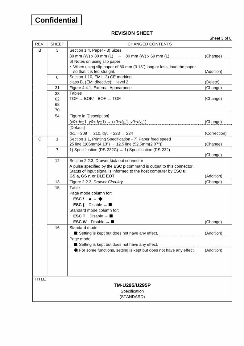
REV. SHEET CHANGED CONTENTS Section 1.4, Paper - 3) Sizes 80 mm (W) x 80 mm (L) → 80 mm (W) x 69 mm (L) (Change)
3
6) Notes on using slip paper • When using slip paper of 80 mm (3.15") long or less, load the paper
so that it is fed straight. (Addition) 6 Section 1.10, EMI - 3) CE marking
class B, (EMI directive): level 2 (Delete) 31 Figure 4.4.1, External Appearance (Change) 38 62 68 70
Tables TOF → BOF/ BOF → TOF (Change)
Figure in [Description] (x0+dx+1, y0+dy+1) → (x0+dx-1, y0+dy-1) (Change)
B
54
[Default] dxL = 209 → 210, dyL = 223 → 224 (Correction)
1 Section 1.1, Printing Specification - 7) Paper feed speed 25 line (105mm(4.13") → 12.5 line (52.5mm(2.07")) (Change)
7 1) Specification (RS-232C) → 1) Specification (RS-232) (Change)
12 Section 2.2.3, Drawer kick-out connector A pulse specified by the ESC p command is output to this connector. Status of input signal is informed to the host computer by ESC u, GS a, GS r, or DLE EOT. (Addition)
13 Figure 2.2.3, Drawer Circuitry (Change) 15 Table
Page mode column for: ESC ! → ESC Disable → Standard mode column for: ESC T Disable → ESC W Disable → (Change) Standard mode : Setting is kept but does not have any effect. (Addition) Page mode : Setting is kept but does not have any effect.
C
16
: For some functions, setting is kept but does not have any effect. (Addition)
TITLE TM-U295/U295P
Specification (STANDARD)
Confidential
REVISION SHEET Sheet 4 of 8
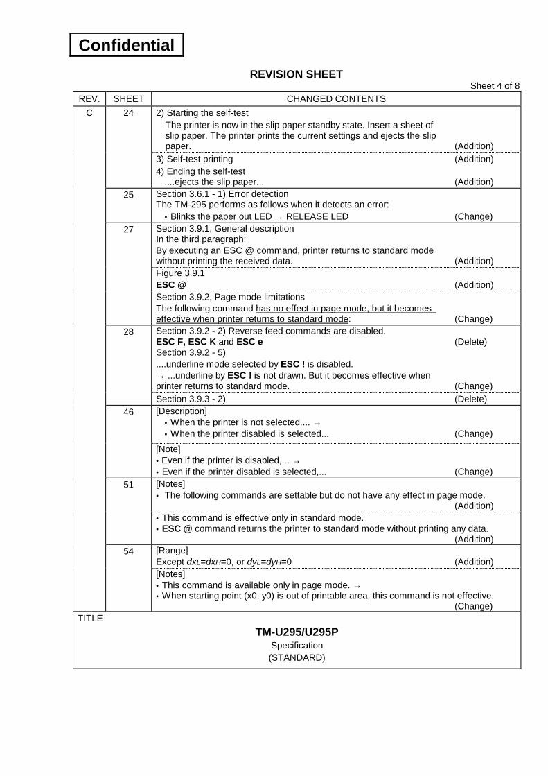
REV. SHEET CHANGED CONTENTS 2) Starting the self-test
The printer is now in the slip paper standby state. Insert a sheet of slip paper. The printer prints the current settings and ejects the slip paper. (Addition)
24
3) Self-test printing (Addition) 4) Ending the self-test
....ejects the slip paper... (Addition) 25 Section 3.6.1 - 1) Error detection
The TM-295 performs as follows when it detects an error: • Blinks the paper out LED → RELEASE LED (Change) Section 3.9.1, General description In the third paragraph: By executing an ESC @ command, printer returns to standard mode without printing the received data. (Addition) Figure 3.9.1 ESC @ (Addition)
27
Section 3.9.2, Page mode limitations The following command has no effect in page mode, but it becomes effective when printer returns to standard mode: (Change) Section 3.9.2 - 2) Reverse feed commands are disabled. ESC F, ESC K and ESC e (Delete) Section 3.9.2 - 5) ....underline mode selected by ESC ! is disabled. → ...underline by ESC ! is not drawn. But it becomes effective when printer returns to standard mode. (Change)
28
Section 3.9.3 - 2) (Delete) [Description] • When the printer is not selected.... → • When the printer disabled is selected... (Change)
46
[Note] • Even if the printer is disabled,... → • Even if the printer disabled is selected,... (Change) [Notes] • The following commands are settable but do not have any effect in page mode.
(Addition)
51
• This command is effective only in standard mode. • ESC @ command returns the printer to standard mode without printing any data. (Addition) [Range] Except dxL=dxH=0, or dyL=dyH=0 (Addition)
C
54
[Notes] • This command is available only in page mode. → • When starting point (x0, y0) is out of printable area, this command is not effective. (Change)
TITLE TM-U295/U295P
Specification (STANDARD)
Confidential
REVISION SHEET Sheet 5 of 8
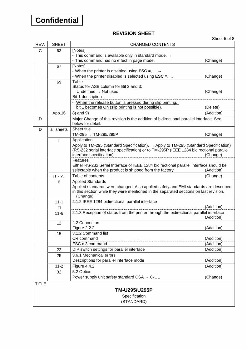
REV. SHEET CHANGED CONTENTS 63 [Notes]
• This command is available only in standard mode. → • This command has no effect in page mode. (Change)
67 [Notes] • When the printer is disabled using ESC =, ... → • When the printer disabled is selected using ESC =, ... (Change) Table Status for ASB column for Bit 2 and 3: Undefined → Not used (Change) Bit 1 description
69
• When the release button is pressed during slip printing, bit 1 becomes On (slip printing is not possible). (Delete)
C
App.16 8) and 9) (Addition) D Major Change of this revision is the addition of bidirectional parallel interface. See
below for detail. all sheets Sheet title
TM-295 → TM-295/295P (Change) Application Apply to TM-295 (Standard Specification). → Apply to TM-295 (Standard Specification) (RS-232 serial interface specification) or to TM-295P (IEEE 1284 bidirectional parallel interface specification). (Change)
I
Features Either RS-232 Serial Interface or IEEE 1284 bidirectional parallel interface should be selectable when the product is shipped from the factory. (Addition)
II - VI Table of contents (Change) 6 Applied Standards
Applied standards were changed. Also applied safety and EMI standards are described in this section while they were mentioned in the separated sections on last revision. (Change) 2.1.2 IEEE 1284 bidirectional parallel interface (Addition)
11-1
11-6 2.1.3 Reception of status from the printer through the bidirectional parallel interface (Addition)
12 2.2 Connectors Figure 2.2.2 (Addition) 3.1.2 Command list CR command (Addition)
15
ESC c 3 command (Addition) 22 DIP switch settings for parallel interface (Addition) 25 3.6.1 Mechanical errors
Descriptions for parallel interface mode (Addition) 31-2 Figure 4.4.2 (Addition)
D
32 5.2 Option Power supply unit safety standard CSA → C-UL (Change)
TITLE TM-U295/U295P
Specification (STANDARD)

Confidential
REVISION SHEET Sheet 6 of 8
REV. SHEET CHANGED CONTENTS 35 CR command details (Addition) 36 DLE EOT
This command is executed even... → With the serial interface model, .... (Change)
38 Table (lower) Bit 6 Off = Slip is not detected.... → Slip is detected... On = Slip is detected.... → Slip is not detected.... (Correction)
42 The way to indicate the command was changed as below. ESC & y c1 c2 [x [d] y × x] c2 - c1 + 1 → ESC & y c1 c2 [x1 d1...d(y × x1)]...[xk d1...d(y × xk)] (Change)
44 The way to indicate the command was changed as below. ESC ∗ m nL nH [d]k → ESC ∗ m nL nH d1...dk (Change)
48 The way to indicate the command was changed as below. ESC D [n] k NUL → ESC D n1...nk NUL (Change)
50 ESC L Change of expression (Change)
54-2 ESC c3 command details (Addition) ESC [Example] When upside-down mode on → When upside-down mode off When upside-down mode off → When upside-down mode on (Correction)
63
(Correction)
64 GS I n Printer model ID = TM-295 → TM-295/TM-295P (Change)
68 Table (lower) Bit 6 On = Slip is detected... → Slip is not detected... (Correction)
72 Ignored Command CR command is added as ignored command. Also the sentence was changed as both ESC c3 and CR commands are ignored with a serial interface model. (Addition/Change)
D
App.17 - App.34
APPENDIX H Bidirectional Parallel Interface (Addition)
TITLE TM-U295/U295P
Specification (STANDARD)
→

Confidential
REVISION SHEET Sheet 7 of 8
REV. SHEET CHANGED CONTENTS 15 • ESC 2 Selects 1/6-inch line spacing.
→ Selects the initial line spacing. (Change) • 2) For parallel interface model I/F nInit reset signal → Internal use, Fixed to ON (Change)
22
Correction and addition are made to the NOTE. (Addition) • DIP switch setting for parallel interface model (Addition) • 1) For serial interface model Correction and addition are made to the NOTE.
(Addition) • 3) Paper-out LED → Paper LED (Change)
23
• Figure 3.4.1 Paper-out LED → Paper LED (Change) 35 • CR Command description is added. (Addition) 38 • Bit 3 The contents of the NOTE are corrected and added.
(Addition) • ESC ! n [Description] “Selects print modes (s)...” → “Selects and cancels print modes (s)...” (Correction)
40
[Notes] Underline mode specification (both selected and not selected) does not have nay effect in page mode. 7 × 7 font specification does not have any effect in page mode. → Underline mode on/off and 7 × 7 font mode on/off are settable but do not have any effect in page mode. (Correction) • ESC 2 Selects 1/6-inch line spacing. → Selects the initial line spacing. (Change) • ESC 2 [Description] 1/6 inch → 4.23mm (1/6 inch) (Change)
• ESC 3 [Description] n/60 inch → n x approx. 0.423mm (1/60 inch) (Change)
45
• ESC 3 [Description] 1/6 inch → 4.23mm (1/6 inch) (Change) 49 • ESC J [Description] n/60 inch → n 5 approx. 0.423mm (1/60 inch) (Change) 50 • ESC K [Description] n/60 inch → n 5 approx. 0.423mm (1/60 inch) (Change) 51 • [Notes] ESC 2 Set 1/6-inch line spacing. → Set the initial line spacing. (Change)
54-2 • [Default] n=48 → n=0 (Change) 60 • [Notes] Since the status is transmitted when this command is buffered
in the receive buffer, → Since this command is stored in the receive buffer and then executed during normal command process, (Change)
62 • [Notes] Since the status is transmitted when this command is buffered in the receive buffer, → Since this command is stored in the receive buffer and then executed during normal command process, (Change)
64 • [Notes] Since the status is transmitted when this command is buffered in the receive buffer, → Since this command is stored in the receive buffer and then executed during normal command process, (Change)
• Bit 0 Not used → Not available for 2-byte code (Change)
E
65 • Bit 1 Not used → No auto cutter (Change)
TITLE TM-U295/U295P
Specification (STANDARD)

Confidential
REVISION SHEET Sheet 8 of 8
REV. SHEET CHANGED CONTENTS 69 • Bit 1 The contents of the NOTE are corrected and added. (Addition)
• [Notes] Since the status is transmitted when this command is buffered in the receive buffer, → Since this command is stored in the receive buffer and then executed during normal command process, (Change)
67
• First Bit 5 Not used 00 0 → Undefined - - (Change)
70 • [Notes] Since the status is transmitted when this command is buffered in the receive buffer, → Since this command is stored in the receive buffer and then executed during normal command process, (Change)
• “CR (ignored only when the model is serial interface model)” is added. (Addition)
E
45 • “Ignored only when the model is serial interface model” is also added for ESC c 3 n.
(Addition) All •Product name
TM-295/295P → TM-U295/U295P (Change) F
1 1.1 Printing Specifications 7) Paper feed speed: 52.9mm/second Table 1.1.1 Characters Per Inch (Change)
6 1.8 Reliability 1) MCBF 1) Life ... 2) Print head life → 2) MCBF ...
3) MTBF ... (Change) All “Confidential” is written in the header of all pages. (Addition) I “Confidentiality Agreement” (Addition) 1 1.2 Character Specifications
... × 3 (tables) → ... × 4 (tables) (Change) 6 1.9 Applied Standards
Descriptions are changed. (Change) 26 3.2.4 Page 19 (PC858: Euro) (Addition) 27 3.2.4 → 3.2.5 (Change) 37 4.2 Color
EPSON standard gray → EPSON standard color (ECW) (Change) 40 5.2 Option
PS-150 → PS170 (Change) 68 ESC t n
n = 19 (Addition)
G
App.17-App.34
Appendix H Bidirectional Parallel Interface (Delete)
8,9 NOTES: (addition) H
14 6) Compatibility Mode tHold-1 (deleted), tHold-2 → tHold, Values in Table (Change)
I 6 1.9 Applicable Standards CE marking is changed for adopting CISPR24.
TITLE TM-U295/U295P
Specification (STANDARD)

Confidential
TITLE SHEET REVISION
NO.
SHEETNEXT G
TM-U295/U295P Specification (STANDARD) II
EPSON
CONFIDENTIALITY AGREEMENT BY USING THIS DOCUMENT, YOU AGREE TO ABIDE BY THE TERMS OF THIS AGREEMENT. PLEASE RETURN THIS DOCUMENT IMMEDIATELY IF YOU DO NOT AGREE TO THESE TERMS.
1. This document contains confidential, proprietary information of Seiko Epson Corporation or its affiliates. You must keep such information confidential. If the user is a business entity or organization, you must limit disclosure to those of your employees, agents and contractors who have a need to know and who are also bound by obligations of confidentiality.
2. On the earlier of (a) termination of your relationship with Seiko Epson, or (b) Seiko Epson's request, you must stop using the confidential information. You must then return or destroy the information, as directed by Seiko Epson.
3. If a court, arbitrator, government agency or the like orders you to disclose any confidential information, you must immediately notify Seiko Epson. You agree to give Seiko Epson reasonable cooperation and assistance in the negotiation.
4. You may use confidential information only for the purpose of operating or servicing the products to which the document relates, unless you obtain the prior written consent of Seiko Epson for some other use.
5. Seiko Epson warrants that it has the right to disclose the confidential information. SEIKO EPSON MAKES NO OTHER WARRANTIES CONCERNING THE CONFIDENTIAL INFORMATION OR ANY OTHER INFORMATION ON THE DOCUMENT, INCLUDING (WITHOUT LIMITATION) ANY WARRANTY OF TITLE OR NON-INFRINGEMENT. Seiko Epson has no liability for loss or damage arising from or relating to your use of or reliance on the information in the document.
6. You may not reproduce, store or transmit the confidential information in any form or by any means (electronic, mechanical, photocopying, recording, or otherwise) without the prior written permission of Seiko Epson.
7. Your obligations under this Agreement are in addition to any other legal obligations. Seiko Epson does not waive any right under this Agreement by failing to exercise it. The laws of Japan apply to this Agreement.
CAUTIONS 1. This document shall apply only to the product(s) identified herein. 2. No part of this document may be reproduced, stored in a retrieval system, or transmitted in any form or
by any means, electronic, mechanical, photocopying, recording, or otherwise, without the prior written permission of Seiko Epson Corporation.
3. The contents of this document are subject to change without notice. Please contact us for the latest information.
4. While every precaution has been taken in the preparation of this document, Seiko Epson Corporation assumes no responsibility for errors or omissions.
5. Neither is any liability assumed for damages resulting from the use of the information contained herein. 6. Neither Seiko Epson Corporation nor its affiliates shall be liable to the purchaser of this product or third
parties for damages, losses, costs, or expenses incurred by the purchaser or third parties as a result of: accident, misuse, or abuse of this product or unauthorized modifications, repairs, or alterations to this product, or (excluding the U. S.) failure to strictly comply with Seiko Epson Corporation's operating and maintenance instructions.
7. Seiko Epson Corporation shall not be liable against any damages or problems arising from the use of any options or any consumable products other than those designated as Original EPSON Products or EPSON Approved Products by Seiko Epson Corporation.
TRADEMARKS EPSON® and ESC/POS® are registered trademarks of Seiko Epson Corporation.
General Notice: Other product and company names used herein are for identification purposes only and may be trademarks of their respective companies.
III

Confidential
TITLE SHEET REVISION
NO.
SHEETNEXT G
TM-U295/U295P Specification (STANDARD) III
EPSON
GENERAL DESCRIPTION
Application These specifications apply to TM-U295(Standard Specification)(RS-232 Serial Interface Specification) or to TM-U295P (IEEE 1284 Bidirectional Parallel Interface Specification).
Features The TM-U295 is terminal slip printer which uses a 7-pin shuttle dot printing method, and provides the different modes, standard and page (∗ ).
The printer has the following features:
• Programmable page length.
• Programmable print starting position.
• Multiple character sizes (standard, double-width, double-height, and quadruple).
• Character directions: 4
• International character set selection.
• Forward and backward paper feeding.
• Command protocol based on the ESC/POSTM standard.
• Programmable paper feed amount.
• Paper eject function.
• Top Of Form (TOF) and Bottom Of Form (BOF) sensors.
• Data reception during printing (improved throughput and less waiting time for the host computer).
• 512 byte printer buffer memory.
• Compact, space efficient design.
• Drawer kick-out function.
• Automatic Status Back (ASB) function to automatically send printer status changes.
• Either RS-232 serial interface or 1284 bidirectional parallel interface should be selectable when the product is shipped from the factory.
∗ In page mode, the print data is buffered within a specified printing area in the memory. After all the data has been buffered in the specified printing area, it is all printed at one time.
III II

Confidential
TITLE SHEET REVISION
NO.
SHEETNEXT G
TM-U295/U295P Specification (STANDARD) III
EPSON
TABLE OF CONTENTS 1. GENERAL SPECIFICATIONS............................................................................................................. 1
1.1 Printing Specifications ................................................................................................................ 1 1.2 Character Specifications............................................................................................................. 1 1.3 Ribbon Cassette ......................................................................................................................... 2 1.4 Paper .......................................................................................................................................... 3 1.5 Receive Buffer ............................................................................................................................ 5 1.6 Electrical Specifications.............................................................................................................. 5 1.7 Environmental Specifications ..................................................................................................... 5 1.8 Reliability..................................................................................................................................... 6 1.9 Applied Standards ...................................................................................................................... 6 1.10 Electrostatic Protection (based on the IEC801-2 test conditions) ............................................ 6
2. CONFIGURATION............................................................................................................................... 7 2.1 Interface...................................................................................................................................... 7
2.1.1 RS-232 serial interface (For serial interface model)........................................................... 7 2.1.2 IEEE 1284 bidirectional parallel interface (For parallel interface model) ......................... 11 2.1.3 Reception of status from the printer through the bidirectional parallel interface .............. 15
2.2 Connectors ............................................................................................................................... 17 2.2.1 Interface connector .......................................................................................................... 17 2.2.2 Power supply connector ................................................................................................... 17 2.2.3 Drawer kick-out connector ............................................................................................... 18
3. FUNCTIONS...................................................................................................................................... 20 3.1 Commands ............................................................................................................................... 20
3.1.1 Command description ...................................................................................................... 20 3.1.2 Command list ................................................................................................................... 21
3.2 Character Code Tables ............................................................................................................ 23 3.2.1 Page 0 (PC437: U.S.A., Standard Europe) ...................................................................... 23 3.2.2 Page 1 (Katakana) ........................................................................................................... 24 3.2.3 Page 2 (PC850: Multilingual)............................................................................................ 25 3.2.4 Page19 (PC858: Euro) ..................................................................................................... 26 3.2.5 International character set................................................................................................ 27
3.3 Buttons and Switches ............................................................................................................... 28 3.3.1 Panel buttons ................................................................................................................... 28 3.3.2 Power switch (located at the left side of the printer)......................................................... 28 3.3.3 DIP switches..................................................................................................................... 28
3.4 Panel LED Indicators ................................................................................................................ 30 3.4.1 Panel LED ........................................................................................................................ 30
3.5 Self-test..................................................................................................................................... 31 3.6 Error Processing....................................................................................................................... 32
3.6.1 Mechanical errors............................................................................................................. 32 3.6.2 Data receive error............................................................................................................. 32
3.7 Paper Sensors .......................................................................................................................... 33 3.7.1 Sensors and LED indicators............................................................................................. 33 3.7.2 Sensors and printing operation ........................................................................................ 33
3.8 Buffer-full Printing ..................................................................................................................... 33 3.9 Page Mode ............................................................................................................................... 34
3.9.1 General descriptions ........................................................................................................ 34 3.9.2 Page mode limitations...................................................................................................... 34 3.9.3 Setting values in standard and page modes .................................................................... 35 3.9.4 Development of print data in the printing area ................................................................. 35
IV III

Confidential
TITLE SHEET REVISION
NO.
SHEETNEXT G
TM-U295/U295P Specification (STANDARD) IV
EPSON
4. CASE SPECIFICATIONS .................................................................................................................. 37 4.1 Overall Dimensions and Weight ............................................................................................... 37 4.2 Color ......................................................................................................................................... 37 4.3 Notes on Transportation ........................................................................................................... 37 4.4 External Appearance ................................................................................................................ 38
5. ACCESSORIES AND OPTION.......................................................................................................... 40 5.1 Standard Accessories............................................................................................................... 40 5.2 Option ....................................................................................................................................... 40
6. COMMAND DESCRIPTIONS............................................................................................................ 41 6.1 Command Notation................................................................................................................... 41 6.2 Command Descriptions ............................................................................................................ 42
HT ................................................................................................................................................ 42 LF................................................................................................................................................. 42 FF................................................................................................................................................. 43 CR................................................................................................................................................ 43 DLE EOT n................................................................................................................................... 44 CAN ............................................................................................................................................. 47 ESC SP n ..................................................................................................................................... 47 ESC ! n......................................................................................................................................... 48 ESC % n ...................................................................................................................................... 49 ESC & y c1 c2 [x1 d1... d(y × x1)]...[xk d1... d(y × xk)] ................................................................ 50 ESC ∗ m nL nH d1...dk ................................................................................................................ 52 ESC 2........................................................................................................................................... 53 ESC 3 n........................................................................................................................................ 53 ESC = n........................................................................................................................................ 54 ESC @ ......................................................................................................................................... 55 ESC C n ....................................................................................................................................... 55 ESC D n1...nk NUL ...................................................................................................................... 56 ESC F n ....................................................................................................................................... 57 ESC J n ........................................................................................................................................ 57 ESC K n ....................................................................................................................................... 58 ESC L........................................................................................................................................... 58 ESC R n ....................................................................................................................................... 60 ESC T n ....................................................................................................................................... 61 ESC W xL xH yL yH dxL dxH dyL dyH ........................................................................................ 62 ESC c 3 n ..................................................................................................................................... 63 ESC c 4 n ..................................................................................................................................... 64 ESC c 5 n ..................................................................................................................................... 65 ESC d n........................................................................................................................................ 65 ESC e n........................................................................................................................................ 66 ESC f t1 t2.................................................................................................................................... 66 ESC p m t1 t2............................................................................................................................... 67 ESC q........................................................................................................................................... 68 ESC t n......................................................................................................................................... 68 ESC u n........................................................................................................................................ 69 ESC v........................................................................................................................................... 71 ESC n ........................................................................................................................................ 72 GS I n ........................................................................................................................................... 73 GS a n .......................................................................................................................................... 75 GS r n........................................................................................................................................... 79
6.3 Ignored Command.................................................................................................................... 81
V IV

Confidential
TITLE SHEET REVISION
NO.
SHEETNEXT G
TM-U295/U295P Specification (STANDARD) V
EPSON
APPENDIX A: MISCELLANEOUS NOTES ................................................................................App.1 APPENDIX B: PRINT DUTY.......................................................................................................App.2 APPENDIX C: NOTES ON USING THE DRAWER KICK-OUT CONNECTOR .........................App.4 APPENDIX D: TRANSMISSION STATUS IDENTIFICATION....................................................App.5 APPENDIX E: EXAMPLE PRINTING IN PAGE MODE..............................................................App.6 APPENDIX F: CHARACTER FONT FORMAT.........................................................................App.10 APPENDIX G: COMPARISON TABLE FOR TM-290II AND TM-U295.....................................App.14
1 V
Confidential
EPSON
TITLE SHEET REVISION
NO.
SHEETNEXT G
TM-U295/U295P Specification (STANDARD) 2 1
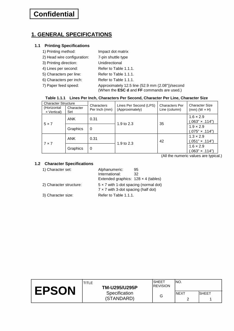
1. GENERAL SPECIFICATIONS
1.1 Printing Specifications 1) Printing method: Impact dot matrix 2) Head wire configuration: 7-pin shuttle type 3) Printing direction: Unidirectional 4) Lines per second: Refer to Table 1.1.1. 5) Characters per line: Refer to Table 1.1.1. 6) Characters per inch: Refer to Table 1.1.1. 7) Paper feed speed: Approximately 12.5 line (52.9 mm (2.08"))/second (When the ESC d and FF commands are used.)
Table 1.1.1 Lines Per Inch, Characters Per Second, Character Per Line, Character Size Character Structure (Horizontal × Vertical)
Character Set
Characters Per Inch (mm)
Lines Per Second (LPS)(Approximately)
Characters Per Line (column)
Character Size (mm) (W × H)
ANK 0.31 1.6 × 2.9 (.063” × .114”) 5 × 7
Graphics 0 1.9 to 2.3 35
1.9 × 2.9 (.075” × .114”)
ANK 0.31 1.3 × 2.9 (.051” × .114”) 7 × 7
Graphics 0 1.9 to 2.3 42
1.6 × 2.9 (.063” × .114”)
(All the numeric values are typical.)
1.2 Character Specifications 1) Character set: Alphanumeric: 95 International: 32 Extended graphics: 128 × 4 (tables) 2) Character structure: 5 × 7 with 1-dot spacing (normal dot) 7 × 7 with 3-dot spacing (half dot) 3) Character size: Refer to Table 1.1.1.

Confidential
EPSON
TITLE SHEET REVISION
NO.
SHEETNEXT G
TM-U295/U295P Specification (STANDARD) 3 2
1.3 Ribbon Cassette 1) Inking method: Exclusive ribbon cassette 2) Color: Purple 3) Part number: ERC-27 4) Life expectancy: Approximately 1,500,000 characters (5 × 7 font) 5) Ribbon cassette overall dimensions: Refer to Figure 1.3.1.
Figure 1.3.1 Ribbon Cassette Overall Dimensions
Confidential
EPSON
TITLE SHEET REVISION
NO.
SHEETNEXT G
TM-U295/U295P Specification (STANDARD) 4 3
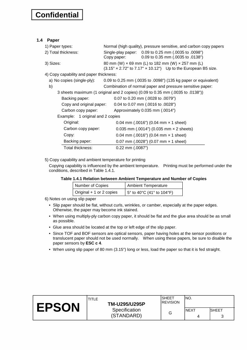
1.4 Paper 1) Paper types: Normal (high quality), pressure sensitive, and carbon copy papers 2) Total thickness: Single-play paper: 0.09 to 0.25 mm (.0035 to .0098") Copy paper: 0.09 to 0.35 mm (.0035 to .0138") 3) Sizes: 80 mm (W) × 69 mm (L) to 182 mm (W) × 257 mm (L) (3.15" × 2.72" to 7.17" × 10.12") Up to the European B5 size. 4) Copy capability and paper thickness:
a) No copies (single-ply): 0.09 to 0.25 mm (.0035 to .0098") (135 kg paper or equivalent) b) Combination of normal paper and pressure sensitive paper:
3 sheets maximum (1 original and 2 copies) (0.09 to 0.35 mm (.0035 to .0138")) Backing paper: 0.07 to 0.20 mm (.0028 to .0079") Copy and original paper: 0.04 to 0.07 mm (.0016 to .0028") Carbon copy paper: Approximately 0.035 mm (.0014")
Example: 1 original and 2 copies Original: 0.04 mm (.0016") (0.04 mm × 1 sheet) Carbon copy paper: 0.035 mm (.0014") (0.035 mm × 2 sheets) Copy: 0.04 mm (.0016") (0.04 mm × 1 sheet) Backing paper: 0.07 mm (.0028") (0.07 mm × 1 sheet) Total thickness: 0.22 mm (.0087")
5) Copy capability and ambient temperature for printing
Copying capability is influenced by the ambient temperature. Printing must be performed under the conditions, described in Table 1.4.1.
Table 1.4.1 Relation between Ambient Temperature and Number of Copies Number of Copies Ambient Temperature Original + 1 or 2 copies 5° to 40°C (41° to 104°F)
6) Notes on using slip paper • Slip paper should be flat, without curls, wrinkles, or camber, especially at the paper edges.
Otherwise, the paper may become ink stained. • When using multiply-ply carbon copy paper, it should be flat and the glue area should be as small
as possible. • Glue area should be located at the top or left edge of the slip paper. • Since TOF and BOF sensors are optical sensors, paper having holes at the sensor positions or
translucent paper should not be used normally. When using these papers, be sure to disable the paper sensors by ESC c 4.
• When using slip paper of 80 mm (3.15") long or less, load the paper so that it is fed straight.

Confidential
EPSON
TITLE SHEET REVISION
NO.
SHEETNEXT G
TM-U295/U295P Specification (STANDARD) 5 4
7) Printing position
Figure 1.4.1 Printing Position NOTES: 1. The mechanical form stopper is adjustable in the range 26.5 to 36.5 mm (1.04 to 1.44"). 2. The TOF and BOF sensors are fixed and cannot be adjusted. 3. After slip paper is set at the mechanical form stopper, the top margin can be shortened
up to 21.2 mm (.83") by feeding the paper backwards (ejection feeding). 4. When ejection feeding is not performed after printing, printing can be performed up to the
position at which the paper edge is no longer held by the paper feed roller (13.8 mm (.54") from the paper edge).
5. When ejection feeding is performed after printing, the paper can be fed forward up to 11.8 mm (.46") (28 dots) after the bottom edge is detected.

Confidential
EPSON
TITLE SHEET REVISION
NO.
SHEETNEXT G
TM-U295/U295P Specification (STANDARD) 6 5
1.5 Receive Buffer Either 512 or 35 bytes is selectable by DIP switches.
1.6 Electrical Specifications 1) Power supply: 24 VDC ± 10% 2) Power consumption
Operating (except for drawer kick-out) a) Mean: Approximately 600 mA at 24 VDC (full-column printing and data transmission of ANK
characters) b) Peak: Approximately 5.5 A at 24 VDC (full-column printing and data transmission of ANK
characters) Standby: Approximately 100 mA (at 24 VDC, 25°C (77°F))
1.7 Environmental Specifications 1) Temperature
Operating: 5° to 40°C (41° to 104°F) Storage: -10° to 50°C (14°F to 86°F) (excluding paper and ribbon)
2) Humidity Operating: 30 to 85% (no condensation) Storage: 30 to 90% (no condensation, excluding paper and ribbon)
3) Vibration resistance When packed: Frequency: 5 to 55 Hz Acceleration: 2 G Sweep: 5 minutes (half cycle) Duration: 1 hour Directions: x, y, and z No external or internal damage should be found after the vibration test, and the printer should operate normally.
4) Impact resistance When packed: Package: EPSON standard package Height: 60 cm (2.36") Directions: 1 corner, 3 edges, 6 surfaces No external or internal damage should be found after the drop test, and the printer should operate normally. When unpacked: Height: 5 cm (.197") Direction: Lift one edge and release it (for all 4 edges) A non-operating printer should not be damaged after it is dropped (for all 4 edges).
5) Acoustic noise: Operating: Approximately 65 dB (Bystander Position)

Confidential
EPSON
TITLE SHEET REVISION
NO.
SHEETNEXT G
TM-U295/U295P Specification (STANDARD) 7 6
1.8 Reliability 1) Life Mechanism: 3,000,000 lines Print head life: 100 million characters
(when in the average of 2 dots/wire per character.) End of life is defined as the point at which the printer reaches the beginning of the Wearout Period.
2) MTBF 180,000 hours Failure is defined as Random Failure occurring at the time of the Random Failure Period.
3) MCBF 7,000,000 lines This is an average failure interval based on failures relating to wearout and random failures up to the life of 3 million lines.
1.9 Applied Standards EMC is measured using SEIKO EPSON’s AC adapter PS-170
1) Europe: CE Marking Directive 89/336/EEC EN55022 Class B EN55024 IEC61000-4-2 IEC61000-4-3 IEC61000-4-4 IEC61000-4-5 IEC61000-4-6 IEC61000-4-11 Directive 90/384/EEC EN45501 Safety: EN60950
2) North America EMI: FCC/ICES-003 Class A Safety standards: UL1950/CSA C22.2 No.950
3) Japan EMI: VCCI Class A
4) Oceania EMC: AS/NZS 3548 Class B
5) Taiwan EMI: Class B
Conditions of Acceptability 1. This Component has been judged on the basis of the required spacing in the Standard for
Information Technology Equipment, including Electrical Business Equipment, UL1950, Sub-clause 2.9, and CSA C22.2 No. 950, Sub-clause 2.11, which would cover the component itself for unrestricted Listing.
2. This unit is intended to be supplied by a limited power source. Should be verified in the end-use product.
3. The terminals and connectors are suitable for field wiring.
1.10 Electrostatic Protection (based on the IEC801-2 test conditions) Air discharge: 8 KV clear level Contact discharge: 4 KV clear level
I

Confidential
EPSON
TITLE SHEET REVISION
NO.
SHEETNEXT G
TM-U295/U295P Specification (STANDARD) 8 7
2. CONFIGURATION
2.1 Interface
2.1.1 RS-232 serial interface (For serial interface model) 1) Specifications
Data transmission: Serial Synchronization: Asynchronous Handshaking: DTR/DSR or XON/XOFF control (selected by DIP switch) Signal level: MARK = -3 to -15 V: Logic "1" SPACE = +3 to +15 V: Logic "0" Baud rates: 1200, 2400, 4800, 9600 bps Data word length: 7 or 8 bit Parity: None, even, odd Stop bit: 1 or more Connector 1: D-SUB25 female connector or equivalent
2) On-line/off-line The printer goes off-line at the following times:
➀ The period from power-on (including reset using interface) until data communication becomes possible after initializing the mechanism.
➁ During the self-test. ➂ During paper feed operation using the paper feed button. ➃ During an error condition.

Confidential
EPSON
TITLE SHEET REVISION
NO.
SHEETNEXT G
TM-U295/U295P Specification (STANDARD) 9 8
3) Interface connector pin assignments and signal functions
Table 2.1.1 TM-U295 Printer Status and Signals Pin number Signal name Input Output Function
1 FG Frame ground 2 TXD Transmit data 3 RXD Receive data 4 RTS Same as the DTR signal 6 DSR Indicates whether the host can receive data. SPACE
indicates that the host can receive data, and MARK indicates that the host cannot receive data. When DTR/DSR control is selected, the printer transmits data after checking this signal. When XON/XOFF control is selected, the printer does not check this signal. Changing DIP switch 1-9 setting enables this signal to be used as a reset signal for the printer (see Section 3.3.1). The printer is reset when the signal remains MARK for 1 ms or more.
7 SG Signal ground 20 DTR Indicates whether the printer can receive data. When
DTR/DSR control is selected, SPACE indicates that the printer can receive data, and MARK indicates that the printer cannot receive data. The signal goes MARK at the following times: • The period from power-on (including reset using interface)
until data communication becomes possible after initializing the mechanism.
• During the self-test. • During paper feed operation using the paper feed button. • During an error condition. • When the receive buffer is full. (See NOTES below)
When XON/XOFF control is selected, the signal is always SPACE except at the following times: • The period from power-on (including reset using interface)
until data communication becomes possible after initializing the mechanism.
• During the self-test. • During an error condition.
25 INIT Changing the DIP switch 1-10 setting enables this signal to be used as a reset signal for the printer (see Section 3.3.1). The printer is reset when the signal remains MARK for 1 ms or more.
NOTES: • When the DIP switch 1-2 is On (the receive buffer capacity is specified to 35 bytes):
When the remaining space in the receive buffer drops to 16 bytes, the printer status becomes "buffer full" and it remains "buffer full" until the space in the receive buffer increases to 26 bytes.
H

Confidential
EPSON
TITLE SHEET REVISION
NO.
SHEETNEXT G
TM-U295/U295P Specification (STANDARD) 10 9
• When the DIP switch 1-2 is Off (the receive buffer capacity is specified to 512 bytes):
When the remaining space in the receive buffer drops to 128 bytes, the printer status becomes "buffer full" and it remains "buffer full" until the space in the receive buffer increases to 138 bytes.
• The printer ignores the data received when the remaining space in the receive buffer is 0 bytes.
4) XON/XOFF timing
When XON/XOFF control is selected, the TM-U295 transmits XON/XOFF signals as follows:
[XON transmission] ➀ When the printer first becomes ready to receive data after turning on the power. ➁ When the receive buffer is released from the buffer full state. ➂ When the printer switches from off-line to on-line.
[XOFF transmission] ➃ When the receive buffer becomes full. ➄ When the printer switches from on-line to off-line.
NOTE: The XON code is 17 (11H) and the XOFF code is 19 (13H). 5) Notes on resetting the printer using the interface
The printer can be reset through the interface (pin 6 or 25) by changing the DIP switch settings accordingly (see Table 2.1.2).
Table 2.1.2 DIP Switch Settings for Resetting the Printer Pin Number DIP switch status Reset Condition Pin 6 (DSR) 1-9 ON MARK level voltage input Pin 25 (INIT) 1-10 ON SPACE or TTL-HIGH level voltage input
To reset the printer, the conditions given below must be satisfied:
Table 2.1.3 Reset Conditions (DC Characteristics) Item Symbol Pin 6 (DSR) Pin 25 (INIT) Reset Active Voltage VA -15 V to -3 V +2 V to +15 V Reset Negative Voltage VN +3 V to +15 V -15 V to +0.8 V Reset Active Current IA -5.3 mA (maximum) 1 mA (maximum) Reset Negative Current IN 5.0 mA (maximum) -2 mA (maximum) Input Impedance RIN 3 kΩ (minimum)
H
Confidential
EPSON
TITLE SHEET REVISION
NO.
SHEETNEXT G
TM-U295/U295P Specification (STANDARD) 11 10
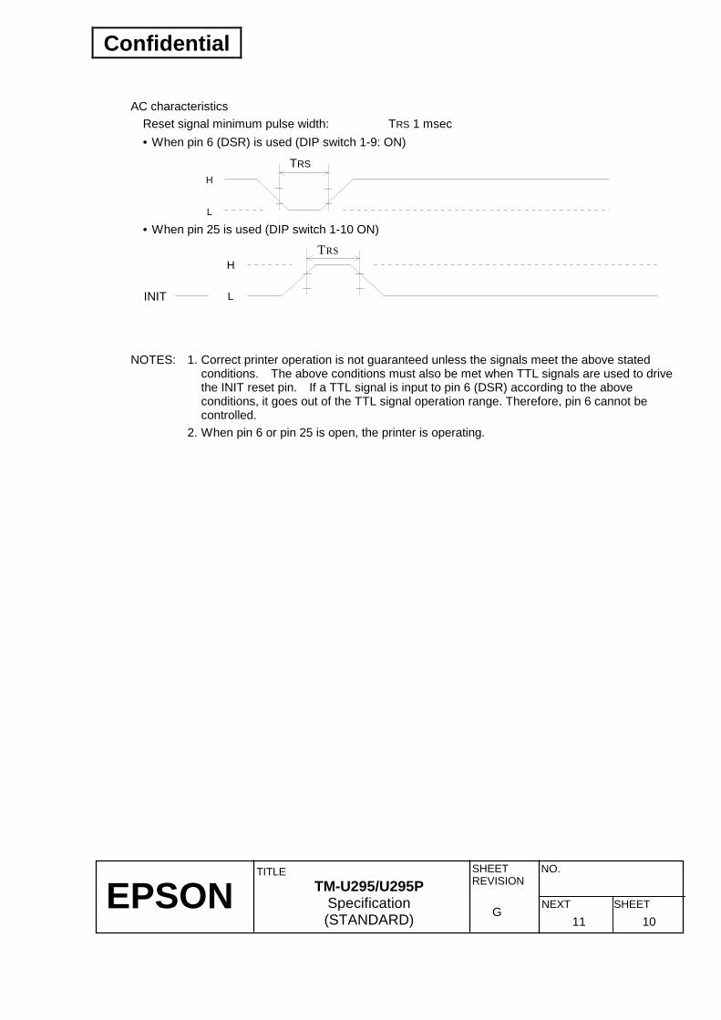
AC characteristics
Reset signal minimum pulse width: TRS 1 msec • When pin 6 (DSR) is used (DIP switch 1-9: ON)
H
L
TRS
• When pin 25 is used (DIP switch 1-10 ON)
H
L
TRS
INIT
NOTES: 1. Correct printer operation is not guaranteed unless the signals meet the above stated
conditions. The above conditions must also be met when TTL signals are used to drive the INIT reset pin. If a TTL signal is input to pin 6 (DSR) according to the above conditions, it goes out of the TTL signal operation range. Therefore, pin 6 cannot be controlled.
2. When pin 6 or pin 25 is open, the printer is operating.

Confidential
EPSON
TITLE SHEET REVISION
NO.
SHEETNEXT G
TM-U295/U295P Specification (STANDARD) 12 11
2.1.2 IEEE 1284 bidirectional parallel interface (For parallel interface model) Copyright 1994 by the Institute of Electrical and Electronic Engineers, Inc. 1) Specifications
Data transmission: 8-bit Parallel Synchronization: Externally supplied nStrobe signals Handshaking: nAck and Busy signals Signal levels: TTL compatible Connector: ADS-B36BLFDR[ SERIES or equivalent (1284 Type B) (HONDA TSUSHIN KOGYO Co.Ltd) Reverse communication (from Printer to Host) from : Nibble or Byte Mode
2) Switching between on-line and off-line
The printer is not equipped with any on-line/off-line switch. The printer is placed into off-line status in either of the followings: • When the power is turned on or until the printer becomes ready for data transmission after it is
initialized by the reset signal (nInit) from the interface. • In the process of self-test. • In the process of paper feeding using the paper feed switch • When an error has occurred.
3) Reverse Mode (Data Transmission from Printer to Host)
The STATUS data transmission from the printer to the host is proceeded in the Nibble or Byte mode. • Description This mode allows data transmission from the asynchronous printer under the control of the host. Data transmissions in the Nibble Mode are made via the existing control lines in units of four bits (Nibble). In the Byte Mode, data transmissions are proceeded by making the eight-bits data lines bidirectional. The both modes fail to be proceeded concurrently with the Compatibility Mode, thereby causing half duplex transmission. For detail description, refer to APPENDIX H. The 1284 Nibble/Byte Modes may be modified without any notice.
Confidential
EPSON
TITLE SHEET REVISION
NO.
SHEETNEXT G
TM-U295/U295P Specification (STANDARD) 13 12
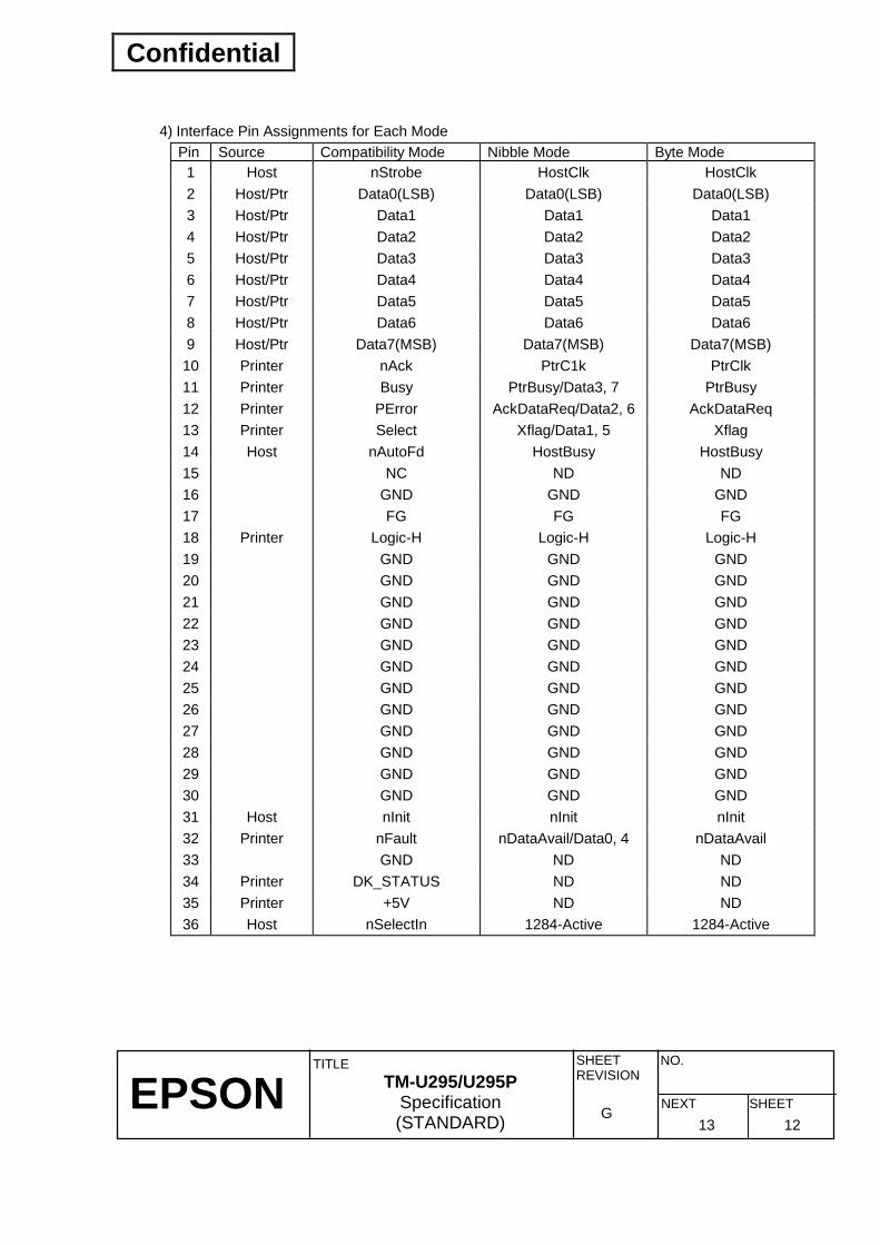
4) Interface Pin Assignments for Each Mode
Pin Source Compatibility Mode Nibble Mode Byte Mode 1 Host nStrobe HostClk HostClk 2 Host/Ptr Data0(LSB) Data0(LSB) Data0(LSB) 3 Host/Ptr Data1 Data1 Data1 4 Host/Ptr Data2 Data2 Data2 5 Host/Ptr Data3 Data3 Data3 6 Host/Ptr Data4 Data4 Data4 7 Host/Ptr Data5 Data5 Data5 8 Host/Ptr Data6 Data6 Data6 9 Host/Ptr Data7(MSB) Data7(MSB) Data7(MSB) 10 Printer nAck PtrC1k PtrClk 11 Printer Busy PtrBusy/Data3, 7 PtrBusy 12 Printer PError AckDataReq/Data2, 6 AckDataReq 13 Printer Select Xflag/Data1, 5 Xflag 14 Host nAutoFd HostBusy HostBusy 15 NC ND ND 16 GND GND GND 17 FG FG FG 18 Printer Logic-H Logic-H Logic-H 19 GND GND GND 20 GND GND GND 21 GND GND GND 22 GND GND GND 23 GND GND GND 24 GND GND GND 25 GND GND GND 26 GND GND GND 27 GND GND GND 28 GND GND GND 29 GND GND GND 30 GND GND GND 31 Host nInit nInit nInit 32 Printer nFault nDataAvail/Data0, 4 nDataAvail 33 GND ND ND 34 Printer DK_STATUS ND ND 35 Printer +5V ND ND 36 Host nSelectIn 1284-Active 1284-Active

Confidential
EPSON
TITLE SHEET REVISION
NO.
SHEETNEXT G
TM-U295/U295P Specification (STANDARD) 14 13
NOTE: 1. A prefix “n” to signal names refers to “L” active signals. To the host provided with none of
the signal lines listed above, both-way communication fails. 2. For interfacing, signal lines shall use twisted pair cables with the return sides connected
to signal ground level. 3. Interfacing conditions shall be all based on the TTL level to meet the characteristics
described below. In addition, both rise time and fall time of each signal shall be 0.5ms or less.
4. Data transmission shall not ignore the signal nAck or Busy. An attempt to transmit data with either signal, nAck or Busy, ignored can cause lost data. (Data transmissions to the printer shall be made after verifying the nAck signal or while the Busy signal is at the “L” level.)
5. Interface cables shall be as minimum required short in length as possible. * NC: No Connect
ND: Not Defined 5) Electrical Characteristics
DC Characteristics (Except Logic-H, + 5 V signals) Specifications Characteristics Symbol Min Max Conditions
Output HIGH voltage Output LOW voltage Output HIGH current Output LOW current
VOH VOL IOH IOL
*2.4 V -0.5 V 0.32 mA -12 mA
5.5 V *0.4 V - -
*IOH=0.32mA *IOL=-12mA VOH=0.32V VOL=0.4V
Input HIGH voltage Input LOW voltage Input HIGH current Input LOW current
VIH VIL VIH VIL
2.0 V - - -
- 0.8 V -0.32 mA 12 mA
VIH=2.0V VIL=0.8V
Logic-H Signal Sender Characteristics Specifications Characteristics Symbol Min Max Conditions
Output HIGH voltage Output LOW voltage
VOH VOL
3.0 V -
5.5 V 2.0 V
While the power is OFF

Confidential
EPSON
TITLE SHEET REVISION
NO.
SHEETNEXT G
TM-U295/U295P Specification (STANDARD) 15 14
+5 V Signal Sender Characteristics Specifications Characteristics Symbol Min Max Conditions
Output HIGH voltage Output LOW voltage Output HIGH current Output LOW current
VOH VOL IOH IOL
*2.4 V - - - **
5.5 V - ** 0.32 mA -
*IOH=0.32mA While the power is OFF VOH=2.4V While the power is OFF
** No guarantee is offered to VOL and IOL while the power is OFF.
6) Compatibility Mode
Specifications Characteristics Symbol Min [ns] Max [ns]
Data Hold Time (host) tHold 750 -- Data Setup Time tSetup 750 -- STROBE Pulse Width tSTB 750 -- READY Cycle Idle Time tReady 0 -- BUSY Output Delay Time tBUSY 0 500 Data Processing Time tReply 0 ∞ ACKNLG Pulse Width tACK 500 10µs BUSY Release Time tBUSY 0 ∞ ACK Cycle Idle Time tNEXT 0 --
* The printer latches data at a falling edge of nStrobe.
Data Data n Data n+1
nStrobe
tSetup tSTB tHold
tReady tBusy
Busy Peripheral Busy
tReply tACK tnBUSY
tNext
nAck
H

Confidential
EPSON
TITLE SHEET REVISION
NO.
SHEETNEXT G
TM-U295/U295P Specification (STANDARD) 16 15
7) Notes on resetting the printer through the interface
The printer reset is available through the interface nInit signal (#31 pin) by changing the DIP switch setting. (Refer to Table 3.3.3 DIP Switch 1.)
Table 2.1.4 DIP Switch Setting for Printer Reset Signal Line DIP Switch Reset Condition #31 Pin (nInit) DSW 1-10: ON TTL-LOW level input
The printer reset through the nInit signal is only available with the SelectIn(1284-Active) signal at LOW. To enable the printer reset, the following signal timing shall be satisfied.
Minimum reset pulse width TR: 50 µµµµs (min)
2.1.3 Reception of status from the printer through the bidirectional parallel interface In the bidirectional parallel interface specifications, the printer status transmission is available by using the both-way communication facility in the Nibble/Byte Modes in accordance with the 1284. In this case, different from in the RS-232 serial interface specifications, the real-time interruptions from the printer to the host are disabled and thus precautions must be taken to the followings. 1) Allowable capacity of the printer internal buffer is 100 bytes (except ASB status). The status signals
exceeding this capacity will be discarded. To prevent possible loss of status, the host shall be ready for data acceptance (Reverse Mode).
2) When ASB is used, the host is preferably in the wait state for data acceptance (Reverse Idle Mode). When this state is not available, the host shall enter the Reverse Mode to always monitor the presence of data.
3) When ASB is used, preference shall be given to the ASB status for transmission over the other status signals. Any accumulated ASB status signals left for transmission from the last to the newest ASB status transmission shall be transmitted together at a time as one ASB status showing the presence of change, followed by the latest ASB status.
min.1ms
nSelectIn (1284-Active)
min.0
nInit min.50µs
TR
Confidential
EPSON
TITLE SHEET REVISION
NO.
SHEETNEXT G
TM-U295/U295P Specification (STANDARD) 17 16
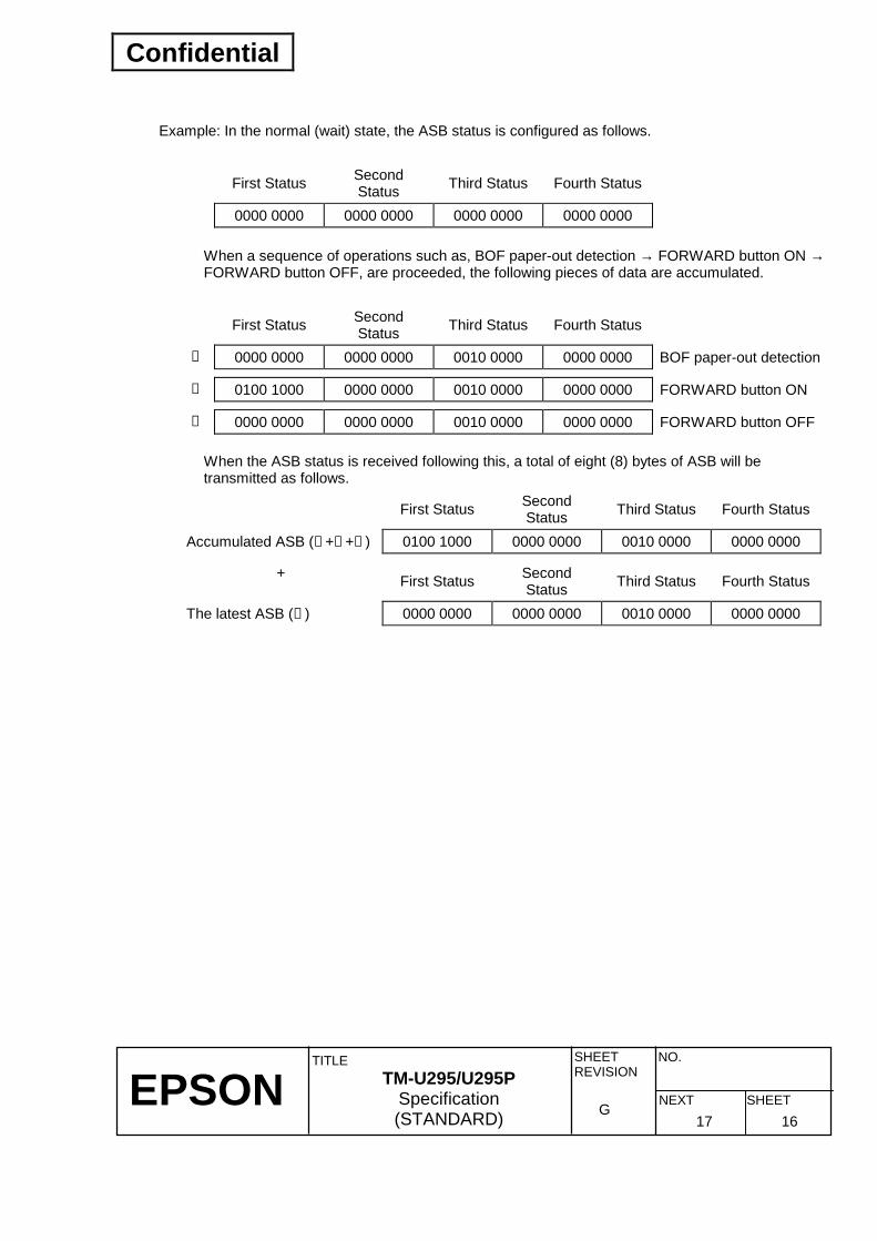
Example: In the normal (wait) state, the ASB status is configured as follows.
First Status Second Status Third Status Fourth Status
0000 0000 0000 0000 0000 0000 0000 0000
When a sequence of operations such as, BOF paper-out detection → FORWARD button ON → FORWARD button OFF, are proceeded, the following pieces of data are accumulated.
First Status Second Status Third Status Fourth Status
➀ 0000 0000 0000 0000 0010 0000 0000 0000 BOF paper-out detection
➁ 0100 1000 0000 0000 0010 0000 0000 0000 FORWARD button ON
➂ 0000 0000 0000 0000 0010 0000 0000 0000 FORWARD button OFF
When the ASB status is received following this, a total of eight (8) bytes of ASB will be transmitted as follows.
First Status Second Status Third Status Fourth Status
Accumulated ASB (➀ +➁ +➂ ) 0100 1000 0000 0000 0010 0000 0000 0000
+ First Status Second Status Third Status Fourth Status
The latest ASB (➂ ) 0000 0000 0000 0000 0010 0000 0000 0000

Confidential
EPSON
TITLE SHEET REVISION
NO.
SHEETNEXT G
TM-U295/U295P Specification (STANDARD) 18 17
2.2 Connectors
DC24VDrawer kick-outconnector
F.GInterface connector
Figure 2.2.1 Serial Interface Connector panel External Appearance
DC24VF.G Drawer kick-outconnector
Interface connector
Figure 2.2.2 Parallel Interface Connector Panel External Appearance
2.2.1 Interface connector Refer to Section 2.1, Interface.
2.2.2 Power supply connector This connector is used to connect an external power source.
1) Pin assignments: Refer to Table 2.2.1. 2) Model: Hosiden TCS7960-532010 3) Host side: Hosiden TCP8927-631110
Table 2.2.1 Power Supply Connector Pin Assignments Pin Number Signal Name 1 +24 VDC 2 GND 3 NC Shell Frame GND

Confidential
EPSON
TITLE SHEET REVISION
NO.
SHEETNEXT G
TM-U295/U295P Specification (STANDARD) 19 18
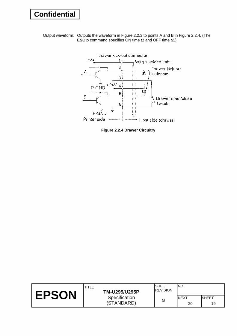
2.2.3 Drawer kick-out connector A pulse specified by the ESC p command is output to this connector. The status of input signal is informed to the host computer by ESC u, GS a, GS r, or DLE EOT.
1) Pin assignments (modular connector)
Table 2.2.2 Drawer Kick-out Connector Pin Assignments Pin Number Signal name Direction
1 Frame GND -- 2 Drawer Kick-out driver signal 1 Output 3 Drawer open/close signal Input 4 +24V -- 5 Drawer kick-out drive signal 2 Output 6 Signal GND --
2) Drawer open/close signal
Input signal level: LOW = 0 V HIGH = 2 to 5 V (at connector pin 3)
3) Drawer kick-out drive signal Output signal: Voltage: Approximately 24 VDC Current: 1 A or less
Figure 2.2.3 Drawer Kick-out Drive Signal Waveform NOTE: The resistance of the drawer kick-out solenoid must not be less than that specified (24 Ω).
Otherwise, an overcurrent could damage the solenoid.
1 6
Confidential
EPSON
TITLE SHEET REVISION
NO.
SHEETNEXT G
TM-U295/U295P Specification (STANDARD) 20 19
Output waveform: Outputs the waveform in Figure 2.2.3 to points A and B in Figure 2.2.4. (The
ESC p command specifies ON time t1 and OFF time t2.)
Figure 2.2.4 Drawer Circuitry

Confidential
EPSON
TITLE SHEET REVISION
NO.
SHEETNEXT G
TM-U295/U295P Specification (STANDARD) 21 20
3. FUNCTIONS
3.1 Commands
3.1.1 Command description The command system of the TM-U295/U295P is based on ESC/POS and has both Standard Mode and Page Mode.
1) Standard Mode The standard command system uses the printer as a common serial terminal printer. Printing and control functions are executed immediately after the commands are received.
2) Page Mode The print command is stored in the specified printable area in memory. After all the data has been stored, the printer prints it at one time.

Confidential
EPSON
TITLE SHEET REVISION
NO.
SHEETNEXT G
TM-U295/U295P Specification (STANDARD) 22 21
3.1.2 Command list Classification Command Name Execution Setting
Standard Mode
Page Mode
Added Command
HT Horizontal tab ∗ ∗ ∗ LF Print and line feed ∗ ∗ ∗ FF Print and eject cut sheet/Print and return to
standard mode ∗ ∗ ∗
CR Print and carriage return ∗ ∗ ∗ DLE EOT Real-time status transmission ∗ ∗ ∗ ∗ CAN Cancel print data in page mode ∗ Disable ∗ ESC SP Set right-side character spacing ∗ ∗ ∗ ESC ! Select print mode(s) ∗ ∗ ESC % Select/cancel user-defined character set ∗ ∗ ∗ ESC & Define user-defined characters ∗ ∗ ∗ ESC ∗∗∗∗ Select bit-image mode ∗ ∗ ESC 2 Select the inital line spacing ∗ ∗ ∗ ESC 3 Set line spacing ∗ ∗ ∗ ESC = Select peripheral device ∗ ∗ ∗ ESC @ Initialize printer ∗ ∗ ∗ ∗ ∗ ESC C Set cut sheet eject length ∗ ∗ ∗ ESC D Set horizontal tab positions ∗ ∗ ∗ ESC F Set/cancel cut sheet reverse eject ∗ ∗ ∗ ESC J Print and feed paper ∗ ∗ ∗ ESC K Print and reverse feed ∗ ∗ Disable ESC L Select page mode ∗ (Line) Disable ESC R Select an international character set ∗ ∗ ∗ ESC T Select print direction in page mode ∗ ∗ ESC W Set printing area in page mode ∗ ∗ ESC c 3 Select paper sensor(s) to output paper end
signals ∗ ∗ ∗
ESC c 4 Select paper sensor(s) to stop printing ∗ ∗ ∗ ESC c 5 Enable/disable panel button ∗ ∗ ∗ ESC d Print and feed n lines ∗ ∗ ∗ ESC e Print and reverse feed n lines ∗ ∗ Disable ESC f Set cut sheet wait time ∗ ∗ ∗ ESC p Generate pulse ∗ ∗ ∗ ESC q Release ∗ ∗ Disable ESC t Select character code table ∗ ∗ ∗ ESC u Transmit peripheral device status ∗ ∗ ∗ ESC v Transmit paper sensor status ∗ ∗ ∗ ESC Turn upside-down printing mode on/off ∗ (Line)

Confidential
EPSON
TITLE SHEET REVISION
NO.
SHEETNEXT G
TM-U295/U295P Specification (STANDARD) 23 22
Command list (continued) Classification Command Name Execution Setting
Standard Mode
Page Mode
Added Command
GS I Transmit printer ID ∗ ∗ ∗ ∗ GS a Enable/disable Automatic Status Back (ASB) ∗ ∗ ∗ ∗ ∗ GS r Transmit status ∗ ∗ ∗ ∗
Command Classification
Execution commands: Printer executes the command function once and does not affect the following data.
Setting commands: The command is retained by a flag and affects the following data. Standard mode: ∗ : Available
(Line):Effective only at the beginning of the line. : Setting is kept but does not have any effect. Page mode: ∗ : Available : Some data is ignored. : Setting is kept but does not have any effect. : For some functions, setting is kept but does not have any effect. Disabled: Parameters are processed as part of the following data.

Confidential
EPSON
TITLE SHEET REVISION
NO.
SHEETNEXT G
TM-U295/U295P Specification (STANDARD) 24 23
3.2 Character Code Tables
3.2.1 Page 0 (PC437: U.S.A., Standard Europe)
NO
TE: T
he a
ctua
l prin
t pat
tern
s di
ffer f
rom
thos
e in
the
abov
e ch
arac
ter c
ode.
Confidential
EPSON
TITLE SHEET REVISION
NO.
SHEETNEXT G
TM-U295/U295P Specification (STANDARD) 25 24
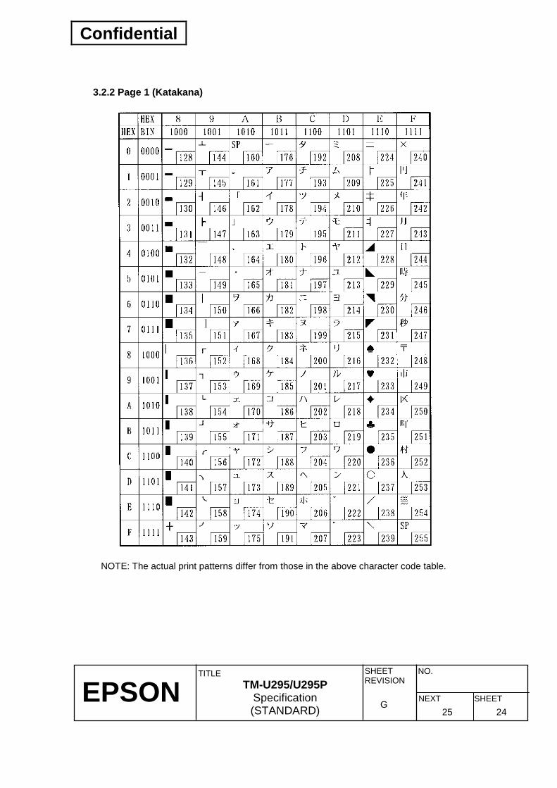
3.2.2 Page 1 (Katakana)
NOTE: The actual print patterns differ from those in the above character code table.

Confidential
EPSON
TITLE SHEET REVISION
NO.
SHEETNEXT G
TM-U295/U295P Specification (STANDARD) 26 25
3.2.3 Page 2 (PC850: Multilingual)
NOTE: The actual print patterns differ from those in the above character code table.
Confidential
EPSON
TITLE SHEET REVISION
NO.
SHEETNEXT G
TM-U295/U295P Specification (STANDARD) 27 26
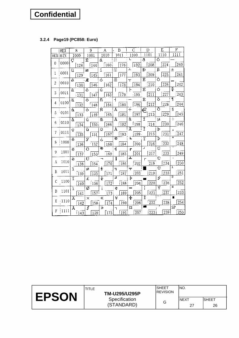
3.2.4 Page19 (PC858: Euro)

Confidential
EPSON
TITLE SHEET REVISION
NO.
SHEETNEXT G
TM-U295/U295P Specification (STANDARD) 28 27
3.2.5 International character set
ASCII codeCountryname
10 Denmark II
9 Norway
8 Japan
7 Spain
6 Italy
5 Sweden
4 Denmark I
3 England
2 Germany
1 France
0 U.S.A.
NOTE: The actual print patterns differ from those in the above character code table.

Confidential
EPSON
TITLE SHEET REVISION
NO.
SHEETNEXT G
TM-U295/U295P Specification (STANDARD) 29 28
3.3 Buttons and Switches
3.3.1 Panel buttons The ESC c 5 command enables the panel buttons. When disabled, none of the buttons will not function.
1) Release button (RELEASE) (Non-locking push button) Function: Release the paper.
2) Reverse button (REVERSE) (Non-locking push button) Function: Feeds paper backward based on the line feed amount set by ESC 2 and ESC 3.
3) Forward button (FORWARD) (Non-locking push button) Function: Feeds paper forward based on the line feed amount set by ESC 2 and ESC 3.
3.3.2 Power switch (located at the left side of the printer) Function: Turns on or off the printer power. To start the self-test, hold down the release button and
press this switch. Note: This switch is located at the left side of the printer. When the printer is turned off using this
switch, the RAM is completely initialized.
3.3.3 DIP switches 1) For serial interface model
Table 3.3.1 DIP Switch 1 DIP Switch
1 Function ON OFF
1 Data receive error Ignored Prints "?". 2 Receive buffer capacity Data buffer 35 bytes Data buffer 512 bytes 3 Handshaking XON/XOFF DTR/DSR 4 Data word length 7 bits 8 bits 5 Parity check Yes No 6 Parity selection Even Odd 7 8
Baud rate selection Transmission speed selection Refer to Table 3.3.2.
9 Pin 6: Reset signal Used Not used 10 Pin 25: Reset signal Used Not used
Confidential
EPSON
TITLE SHEET REVISION
NO.
SHEETNEXT G
TM-U295/U295P Specification (STANDARD) 30 29
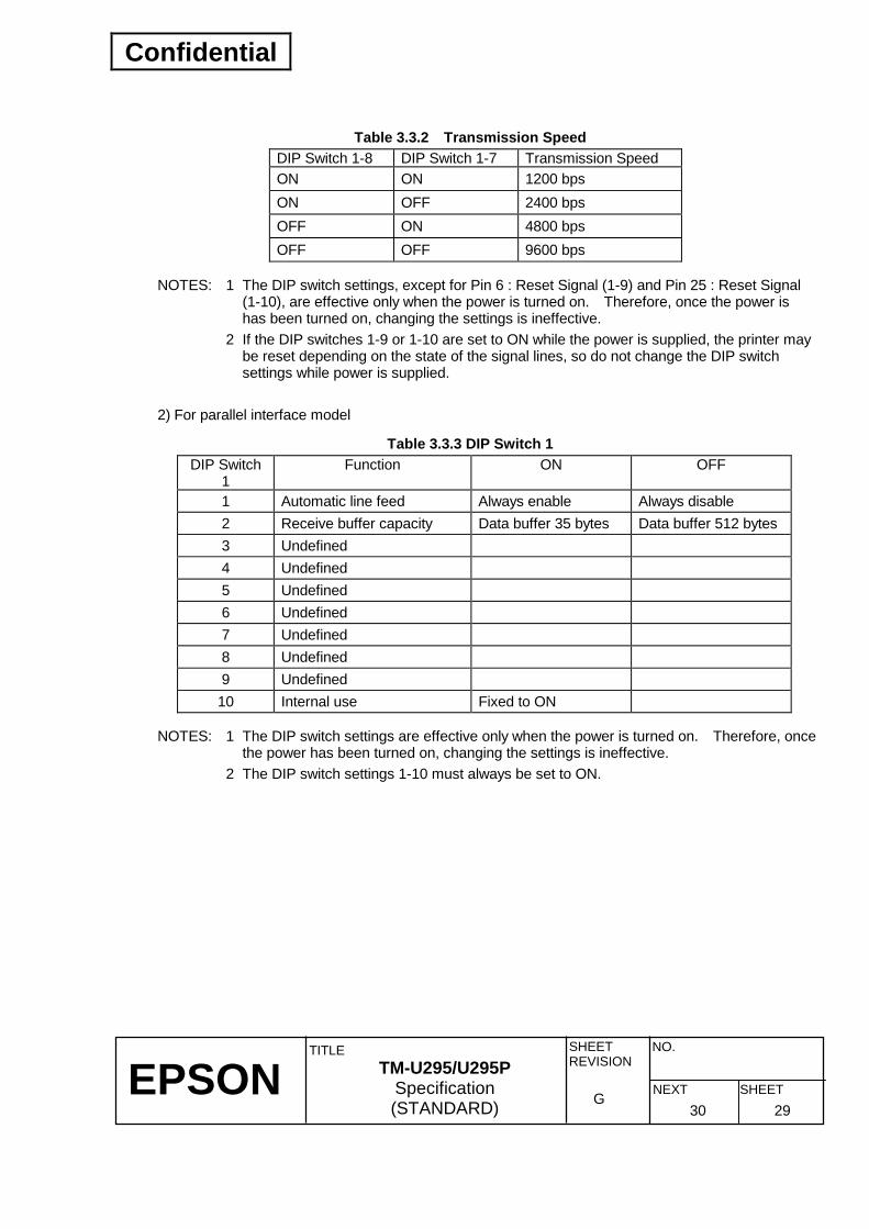
Table 3.3.2 Transmission Speed DIP Switch 1-8 DIP Switch 1-7 Transmission Speed ON ON 1200 bps ON OFF 2400 bps OFF ON 4800 bps OFF OFF 9600 bps
NOTES: 1 The DIP switch settings, except for Pin 6 : Reset Signal (1-9) and Pin 25 : Reset Signal (1-10), are effective only when the power is turned on. Therefore, once the power is has been turned on, changing the settings is ineffective.
2 If the DIP switches 1-9 or 1-10 are set to ON while the power is supplied, the printer may be reset depending on the state of the signal lines, so do not change the DIP switch settings while power is supplied.
2) For parallel interface model
Table 3.3.3 DIP Switch 1 DIP Switch
1 Function ON OFF
1 Automatic line feed Always enable Always disable 2 Receive buffer capacity Data buffer 35 bytes Data buffer 512 bytes 3 Undefined 4 Undefined 5 Undefined 6 Undefined 7 Undefined 8 Undefined 9 Undefined 10 Internal use Fixed to ON
NOTES: 1 The DIP switch settings are effective only when the power is turned on. Therefore, once the power has been turned on, changing the settings is ineffective.
2 The DIP switch settings 1-10 must always be set to ON.

Confidential
EPSON
TITLE SHEET REVISION
NO.
SHEETNEXT G
TM-U295/U295P Specification (STANDARD) 31 30
3.4 Panel LED Indicators
3.4.1 Panel LED
1) Power LED (POWER): Green On: Power supply of +24 V is stable. Off: Power supply of +24 V is not stable.
2) Release LED (RELEASE): Green On: Paper release state (paper can be manually repositioned.) Off: Paper clamp state (paper is held by the printer.) Blinking: Error state.
3) Paper LED (PAPER OUT) : Red On: Either BOF or TOF sensor has detected the paper out state (it lights regardless of
whether sensors are enabled/disabled.) Off: Both BOF and TOF sensors detect paper.
Release button
Reverse button
Forward button
Paper LED: Red
Release LED: Green
Power LED: Green
RELEASE
REVERSE
FORWARD
RELEASE
PAPER OUT
POWER
Figure 3.4.1 Panel Buttons and Indicators
Confidential
EPSON
TITLE SHEET REVISION
NO.
SHEETNEXT G
TM-U295/U295P Specification (STANDARD) 32 31
3.5 Self-test
1) The printer has a self-test that checks the following: • Control circuit functions • Printer mechanisms • Print quality • Control ROM version • RAM • DIP switch settings
2) Starting the self-test To start the self-test on slip paper, hold down the RELEASE button while you turn on the printer. Then release the RELEASE button. The printer is now in the slip paper standby state. Insert a sheet of slip paper. The printer prints the current settings and ejects the slip paper.
3) Self-test printing Press the RELEASE button. Insert another sheet of slip paper and the printer will print characters from its character sets. During the self test, the printer will stop whenever it is out of paper. When this happens, press the RELEASE button and insert another sheet of slip paper.
4) Ending the self-test Continue this process until the printer indicates the end of the self test by printing "∗∗∗ completed ∗∗∗ ", ejects the slip paper, and goes into the normal mode.

Confidential
EPSON
TITLE SHEET REVISION
NO.
SHEETNEXT G
TM-U295/U295P Specification (STANDARD) 33 32
3.6 Error Processing
3.6.1 Mechanical errors 1) Error detection
The TM-U295/U295P detects the following mechanical error states: • Abnormal load due to paper jams. • Abnormal home position error. • Abnormal timing error. • Drive circuit error. • Power supply voltage error (only at power-on)
The TM-U295/U295P performs as follows when it detects an error:
<Serial interface model> • Stops all mechanical operation. • Sets the DTR signal to MARK. • Blinks the RELEASE LED. • Transmits XOFF if XON/XOFF control is selected.
<Parallel interface model> • Stops all mechanical operation. • Sets the Busy signal to HIGH. • Blinks the RELEASE LED. • Sets the nFault signal to LOW.
2) Error recovery
The TM-U295/U295P recovers from an error state by turning off the power, correcting the error, and then turning the power back on.
3.6.2 Data receive error If a parity, framing, or overrun error occurs, the printer ignores the corresponding data or prints a question mark (?), according to the setting of DIP switch 1-1.

Confidential
EPSON
TITLE SHEET REVISION
NO.
SHEETNEXT G
TM-U295/U295P Specification (STANDARD) 34 33
3.7 Paper Sensors Two types of paper sensors are equipped as follows:
• TOF sensor • BOF sensor
3.7.1 Sensors and LED indicators The paper out LED indicator lights when either the BOF or TOF sensor detects a paper-out, regardless of whether the sensor is enabled or disabled.
3.7.2 Sensors and printing operation When a paper-out is detected, whether printing stops or not is selected by ESC c 4. The related sensors are as follows:
• TOF sensor • BOF sensor
When printing stops by detecting a paper-out, the printer stops after printing and feeding the current line. If the panel buttons are disabled, the printer automatically releases the paper and waits for another slip to be inserted.
3.8 Buffer-full Printing When more print data is received after processing one line of data, the printer automatically prints the processed data and feeds the paper one line.

Confidential
EPSON
TITLE SHEET REVISION
NO.
SHEETNEXT G
TM-U295/U295P Specification (STANDARD) 35 34
3.9 Page Mode
3.9.1 General descriptions The printer operates in two modes: standard mode and page mode. In standard mode, the printer prints and feeds paper each time it receives print and paper feed commands. In page mode, all the received print and paper feed commands are processed in the specified memory, and the printer executes no operations. All the data in the memory is then printed collectively when an FF command is received. For example, when the printer prints the data "ABCDEF" and feeds the line, "ABCDEF" is printed and the paper is fed one line in standard mode. In page mode, "ABCDEF" is written to the specified printing area in memory, and the position in memory for the next print data is shifted by one line. The ESC L command puts the printer into page mode and commands received thereafter are processed in page mode. Executing an FF command collectively prints the received data and then restores the printer to standard mode. By executing an ESC @ command, printer returns to standard mode without printing the received data.
Standard Mode
FF, ESC @
ESC L
Page Mode
Figure 3.9.1 Print Modes
3.9.2 Page mode limitations Page mode has the following limitations:
1) Half-dots are not usable Page mode can handle only normal dots. Therefore, the 7 × 7 dot font, user-defined characters including half-dots, and bit images cannot be specified. Since setting values with the ESC SP and ESC D commands use half-dot reference, these values must be converted into values referenced to normal dots. Under these command conditions, displacement by one half-dot may occur. The following command has no effect in page mode, but it becomes effective when printer returns to standard mode:
• 7 × 7 font specification using ESC !. The following specifications are disabled in page mode:
• Double-density bit image specification using ESC ∗∗∗∗ .

Confidential
EPSON
TITLE SHEET REVISION
NO.
SHEETNEXT G
TM-U295/U295P Specification (STANDARD) 36 35
2) Reverse feed commands are disabled.
In page mode, data can be written freely in the specified printing area. Therefore, the following commands which feeds paper in reverse direction is disabled:
ESC K, and ESC e
3) Up-side down printing mode has no effect in page mode. In page mode, characters and bit images can be rotated in increments of 90°, and also printing is available any of four directions. Therefore, the ESC command which turns on or off up-side down printing mode has no effect in page mode.
4) Double-strike printing cannot be performed. In page mode, data written twice to the same area is logically OR'ed before printing. Therefore, double-strike mode cannot be used to emphasize characters.
5) Underline mode has no effect in page mode. In page mode, because characters and bit images can be overlapped, underline by ESC ! is not drawn. But it becomes effective when printer returns to standard mode. In this case, bit images can be used, instead of underline mode. (Broken line, wavy line, etc. are also available.)
3.9.3 Setting values in standard and page modes 1) The values set by commands are common to both standard and page modes. However, values
are set independently in each mode for ESC SP, ESC 2, and ESC 3.
2) Although the maximum number of printable dots for a bit image is 210 in standard mode, 480 bit-image dots can be printed in the y direction (paper feeding direction) in page mode. This is possible only when 480 printable-area dots in the y direction have been specified using ESC W, and the printing direction value n in the ESC T command is 1 or 3).
3.9.4 Development of print data in the printing area Development of print data in the printing area is performed as follows: ➀ The printing area is set using ESC W. When all printing and feeding are complete before the printer
receives the ESC W command, the left side as you face the printer is taken as the origin (x0, y0) of the printing area. The printing rectangular area is defined by the length (dx dots) extending from and including the origin (x0, y0) in the x direction (perpendicular to the paper feed direction), and by the length (dy dots) in the y direction (paper feed direction).
When the printer receives print data after ESC W sets the printing area and ESC T sets the printing direction, the print data is developed within the printing area so that the highest dot of the print data is at the beginning of the printing area. (See the ESC ∗∗∗∗ command description in Section 6.2 and Appendix F)
Since print data containing double-height and quadruple-size characters is developed so that only the lower 7 dots of these characters are included in the printing area, execute a line feed (LF) before the print data to allow the remaining higher dots to be printed.

Confidential
EPSON
TITLE SHEET REVISION
NO.
SHEETNEXT G
TM-U295/U295P Specification (STANDARD) 37 36
➁ If the print data exceeds the printing area (including the space to the right of a character) before a
command that is followed by line feeding (LF, ESC J, etc.) is received, line feeding is executed automatically within the printing area. The development position therefore moves to the beginning of the next line. The line feed amount depends on the values set by command (ESC 2, ESC 3, etc.).
If the print data for the next line contains double-height or quadruple-size characters, the amount of line feeding may be insufficient, resulting in overlapping of the characters' higher-order dots with the previous line. To avoid this, increase the amount of line feeding.

Confidential
EPSON
TITLE SHEET REVISION
NO.
SHEETNEXT G
TM-U295/U295P Specification (STANDARD) 38 37
4. CASE SPECIFICATIONS
4.1 Overall Dimensions and Weight Height: 101.5 mm (4.0") Width: 180 mm (7.09") Depth: 190.5 mm (7.50") (except for the interface connector projection) Weight: Approximately 1.6 kg (3.52 lbs)
4.2 Color EPSON standard color (ECW)
4.3 Notes on Transportation Before repacking and storing the printer, move the print head to the left and insert the damper. (Release the printer by pressing the RELEASE button, then press the FORWARD button, and the print head is moved to the left automatically.)

Confidential
EPSON
TITLE SHEET REVISION
NO.
SHEETNEXT G
TM-U295/U295P Specification (STANDARD) 39 38
4.4 External Appearance
Figure 4.4.1 External Appearance (Serial interface model)
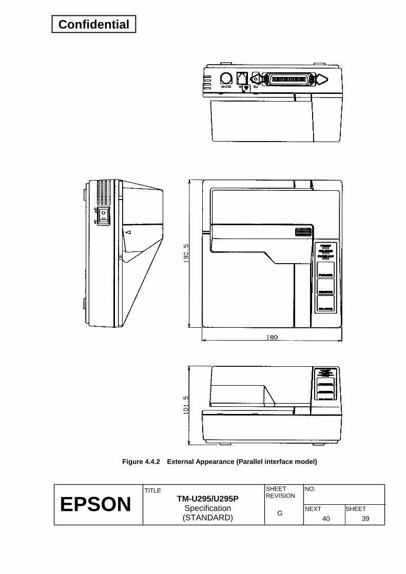
Confidential
EPSON
TITLE SHEET REVISION
NO.
SHEETNEXT G
TM-U295/U295P Specification (STANDARD) 40 39
Figure 4.4.2 External Appearance (Parallel interface model)

Confidential
EPSON
TITLE SHEET REVISION
NO.
SHEETNEXT G
TM-U295/U295P Specification (STANDARD) 41 40
5. ACCESSORIES AND OPTION
5.1 Standard Accessories • Exclusive ribbon cassette • Installation manual • Hexagon lock screws (mm-size, only for overseas's specifications)
5.2 Option External power supply PS-170
Exclusive power supply unit: EPSON PS-170 Specifications
Input: 90 to 132 VAC/198 to 264 VAC AC inlet type Power supply type is selectable depending on country (North America,
Europe I, Europe II, and Japan). Output: 24 VDC with exclusive DC cable Size: 86 mm (W) × 166 mm (D) × 44 mm (H) (3.39" × 6.54" × 1.73") Case material: Plastic (black) Safety standards: UL/C-UL/TÜV (already certified) CE marking Already acquired
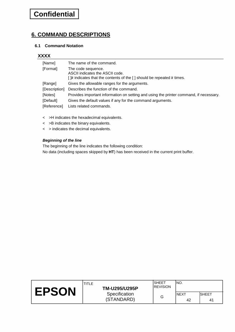
Confidential
EPSON
TITLE SHEET REVISION
NO.
SHEETNEXT G
TM-U295/U295P Specification (STANDARD) 42 41
6. COMMAND DESCRIPTIONS
6.1 Command Notation
XXXX [Name] The name of the command. [Format] The code sequence.
ASCII indicates the ASCII code. [ ]k indicates that the contents of the [ ] should be repeated k times.
[Range] Gives the allowable ranges for the arguments. [Description] Describes the function of the command. [Notes] Provides important information on setting and using the printer command, if necessary. [Default] Gives the default values if any for the command arguments. [Reference] Lists related commands. < >H indicates the hexadecimal equivalents. < >B indicates the binary equivalents. < > indicates the decimal equivalents. Beginning of the line The beginning of the line indicates the following condition: No data (including spaces skipped by HT) has been received in the current print buffer.

Confidential
EPSON
TITLE SHEET REVISION
NO.
SHEETNEXT G
TM-U295/U295P Specification (STANDARD) 43 42
6.2 Command Descriptions
HT [Name] Horizontal tab [Format] ASCII HT
Hex 09 Decimal 9
[Description] Moves the print position to the next horizontal tab position. [Notes] • Horizontal tab positions are set with ESC D. • This command is ignored unless the next horizontal tab position has been set. • The default tab positions are at intervals of 8 characters in the 5 × 7 font (9th column,
17th column, 25th column ... ). [Reference] ESC D
LF [Name] Print and line feed [Format] ASCII LF
Hex 0A Decimal 10
[Description] Prints the data in the print buffer and feeds one line based on the current line spacing. [Note] This command sets the print position to the beginning of the line. [Reference] ESC 2, ESC 3
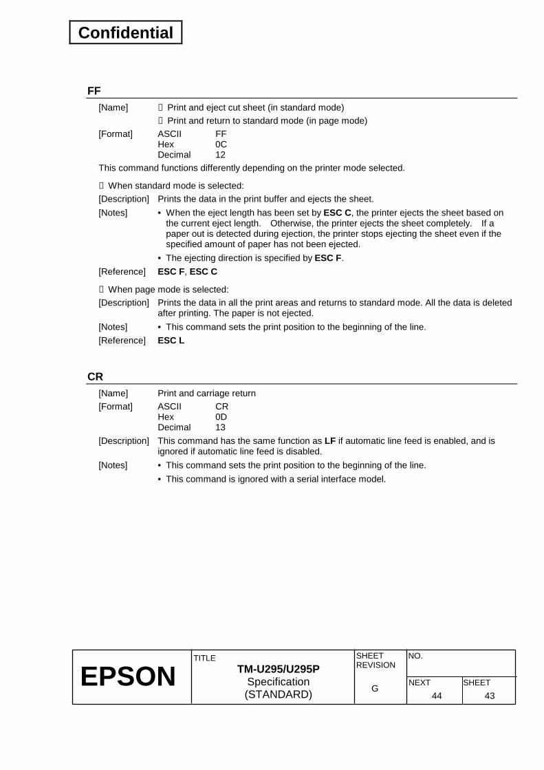
Confidential
EPSON
TITLE SHEET REVISION
NO.
SHEETNEXT G
TM-U295/U295P Specification (STANDARD) 44 43
FF [Name] ➀ Print and eject cut sheet (in standard mode) ➁ Print and return to standard mode (in page mode) [Format] ASCII FF
Hex 0C Decimal 12
This command functions differently depending on the printer mode selected.
➀ When standard mode is selected: [Description] Prints the data in the print buffer and ejects the sheet. [Notes] • When the eject length has been set by ESC C, the printer ejects the sheet based on
the current eject length. Otherwise, the printer ejects the sheet completely. If a paper out is detected during ejection, the printer stops ejecting the sheet even if the specified amount of paper has not been ejected.
• The ejecting direction is specified by ESC F. [Reference] ESC F, ESC C
➁ When page mode is selected: [Description] Prints the data in all the print areas and returns to standard mode. All the data is deleted
after printing. The paper is not ejected. [Notes] • This command sets the print position to the beginning of the line. [Reference] ESC L
CR [Name] Print and carriage return [Format] ASCII CR
Hex 0D Decimal 13
[Description] This command has the same function as LF if automatic line feed is enabled, and is ignored if automatic line feed is disabled.
[Notes] • This command sets the print position to the beginning of the line. • This command is ignored with a serial interface model.

Confidential
EPSON
TITLE SHEET REVISION
NO.
SHEETNEXT G
TM-U295/U295P Specification (STANDARD) 45 44
DLE EOT n [Name] Real-time status transmission [Format] ASCII DLE EOT n
Hex 10 04 n Decimal 16 4 n
[Range] 1 ≤ n ≤ 3, n = 5 [Description] Transmits the selected printer status specified by n in real time, according to the
following parameters: n = 1: Transmits printer status.
n = 2: Transmits off-line status. n = 3: Transmits error status. n = 5: Transmits slip paper status.
[Notes] • Printer status data which can be transmitted are shown on the following pages. • The printer executes this command upon receiving it. • The printer transmits one byte of the status data without confirming the DSR signal
status. • With the serial interface model, this command is executed even if the printer is off-line
or receive buffer is full. However, with the parallel interface model, this command can not be executed if the printer is off-line or receive buffer is full, since the printer is busy and unable to receive this command.
• This command is transmitted anytime the data sequence 16 (10H) 4 (04H) n (1 ≤ n ≤ 3, n = 5) is received, even if it appears as part of another command.
Example In ESC ∗ m nL nH [d] nL + 256 × nH, d1 = 16 (10H), d2 = 4 (04H), d3 = 1 (1H)
• This command should not be used within the data sequence of another command that consists of two or more bytes.
Example When attempting to transmit ESC 3 n to the printer and DLE EOT 3 is transmitted, the
code 16 (10H) for DLE EOT 3 is processed as the code for ESC 3 16 (10H). • When Auto Status Back (ASB) is enabled using GS a, the status transmitted by ESC
EOT and the ASB status must be differentiated by using the table in Appendix D. • If n is out of the specified range, this command is ignored.

Confidential
EPSON
TITLE SHEET REVISION
NO.
SHEETNEXT G
TM-U295/U295P Specification (STANDARD) 46 45
• The status data transmitted is shown in the following table: n = 1: Printer status
Bit Off/On Hex Decimal Function 0 Off 00 0 Not used. Fixed to Off. 1 On 02 2 Not used. Fixed to On.
Off 00 0 Drawer kick-out signal is LOW (connector pin 3).2 On 04 4 Drawer kick-out signal is HIGH (connector pin 3).Off 00 0 On-line. 3 On 08 8 Off-line.
4 On 10 16 Not used. Fixed to On. Off -- -- Undefined. 5 On -- -- Undefined. Off -- -- Undefined. 6 On -- -- Undefined.
7 Off 00 0 Not used. Fixed to Off.
n = 2: Off-line status Bit Off/On Hex Decimal Function 0 Off 00 0 Not used. Fixed to Off. 1 On 02 2 Not used. Fixed to On.
Off -- -- Undefined. 2 On -- -- Undefined. Off 00 0 Paper is not being fed by the paper feed button. 3 On 08 8 Paper is being fed by the paper feed button.
4 On 10 16 Not used. Fixed to On. Off 00 0 No paper-end stop. 5 On 20 32 Printing stops due to paper-end. Off 00 0 No error. 6 On 40 64 Error occurs.
7 Off 00 0 Not used. Fixed to Off. Bit 5: The printer will stop printing and “32” (printing currently stopped) occurs if a
paper-end is detected by TOF or BOF sensor when paper-end printing stop is selected by ESC c 4.

Confidential
EPSON
TITLE SHEET REVISION
NO.
SHEETNEXT G
TM-U295/U295P Specification (STANDARD) 47 46
n = 3: Error status
Bit Off/On Hex Decimal Function 0 Off 00 0 Not used. Fixed to Off. 1 On 02 2 Not used. Fixed to On.
Off -- -- Undefined. 2 On -- -- Undefined. Off -- -- Undefined. 3 On -- -- Undefined.
4 On 10 16 Not used. Fixed to On. Off 00 0 No unrecoverable error. 5 On 20 32 Unrecoverable error occurred. Off -- -- Undefined. 6 On -- -- Undefined.
7 Off 00 0 Not used. Fixed to Off. n = 5: Slip paper status
Bit Off/On Hex Decimal Function 0 Off 00 0 Not used. Fixed to Off. 1 On 02 2 Not used. Fixed to On. 2 Off 00 0 Slip paper selected.
Off 00 0 Does not wait for slip paper insertion. 3 On 08 8 Waits for slip paper insertion.
4 On 10 16 Not used. Fixed to On. Off 00 0 Slip is detected by the BOF sensor. 5 On 20 32 Slip is not detected by the BOF sensor. Off 00 0 Slip is detected by the TOF sensor. 6 On 40 64 Slip is not detected by the TOF sensor.
7 Off 00 0 Not used. Fixed to Off. Bit 3: Switches to “1” (waiting for paper insertion) at the end of current printing
operation, if print stop is selected when paper-end is detected by ESC c 4 as well as subsequent print data being present.
Switches to “0” (not waiting for paper insertion) just before actual slip selection takes place after slip paper is detected.
Bit 5 and 6: Transmits the current status of the TOF and BOF sensors. [Reference] ESC u, ESC v, GS a, Appendix D: Transmission Status Identification

Confidential
EPSON
TITLE SHEET REVISION
NO.
SHEETNEXT G
TM-U295/U295P Specification (STANDARD) 48 47
CAN [Name] Cancel print data in page mode [Format] ASCII CAN
Hex 18 Decimal 24
[Description] In page mode, deletes all the print data in the current printable area. [Notes] • This command is enabled only in page mode. • If data that existed in the previously specified printable area also exists in the currently
specified printable area, it is deleted. [Reference] ESC W
ESC SP n [Name] Set right-side character spacing [Format] ASCII ESC SP n
Hex 1B 20 n Decimal 27 32 n
[Range] 0 ≤ n ≤ 32 [Description] Sets the character spacing for the right side of the character. [Notes] • The right-side character spacing for double-width mode is twice the normal value. • The character spacing is set in increment of half dot. • In page mode, the actual dot positions shift by half dot. • This command sets values independently in standard mode and in page mode. [Default] n = 0 [Reference] Section 3.9.2, Page Mode Limitations

Confidential
EPSON
TITLE SHEET REVISION
NO.
SHEETNEXT G
TM-U295/U295P Specification (STANDARD) 49 48
ESC ! n [Name] Select print mode(s) [Format] ASCII ESC ! n
Hex 1B 21 n Decimal 27 33 n
[Range] 0 ≤ n ≤ 255 [Description] Selects and cancels print mode(s) using n as follows:
Bit Off/On Hex Decimal Function Off 00 0 5 × 7 font selected. 0 On 01 1 7 × 7 font selected. Off -- -- Undefined. 1 On -- -- Undefined. Off -- -- Undefined. 2 On -- -- Undefined. Off -- -- Undefined. 3 On -- -- Undefined. Off 00 0 Double-height mode not selected. 4 On 10 16 Double-height mode selected. Off 00 0 Double-width mode not selected. 5 On 20 32 Double-width mode selected. Off -- -- Undefined. 6 On -- -- Undefined. Off 00 0 Underline mode not selected. 7 On 80 128 Underline mode selected.
[Notes] • All the printed characters are underlined, except for a space set by an HT. • When both double-height and double-width modes are set, quadruple-size characters
are printed. • Underline mode on/off and 7 × 7 font mode on/off are settable but do not have any
effect in page mode. [Default] n = 0 [Reference] Section 3.9.2, Page Mode Limitations

Confidential
EPSON
TITLE SHEET REVISION
NO.
SHEETNEXT G
TM-U295/U295P Specification (STANDARD) 50 49
ESC % n [Name] Select/cancel user-defined character set [Format] ASCII ESC % n
Hex 1B 25 n Decimal 27 37 n
[Range] 0 ≤ n ≤ 255 [Description] Selects or cancels the user-defined character set. • Only the LSB of n is effective.
When n = <∗∗∗∗∗∗∗ 0>B, the user-defined character set is canceled (internal character set is selected).
When n = <∗∗∗∗∗∗∗ 1>B, the user-defined character set is selected. [Default] n = 0 [Reference] ESC &
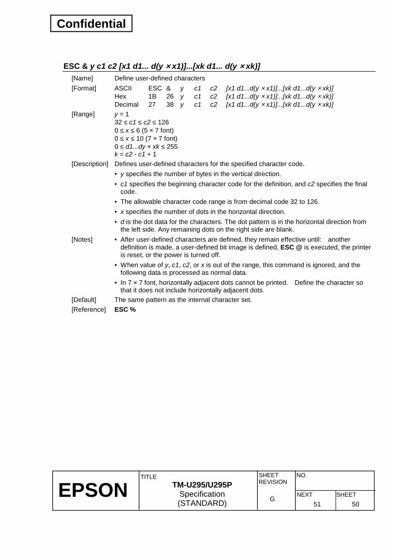
Confidential
EPSON
TITLE SHEET REVISION
NO.
SHEETNEXT G
TM-U295/U295P Specification (STANDARD) 51 50
ESC & y c1 c2 [x1 d1... d(y ×××× x1)]...[xk d1... d(y ×××× xk)] [Name] Define user-defined characters [Format] ASCII ESC & y c1 c2 [x1 d1...d(y × x1)]...[xk d1...d(y × xk)]
Hex 1B 26 y c1 c2 [x1 d1...d(y × x1)]...[xk d1...d(y × xk)] Decimal 27 38 y c1 c2 [x1 d1...d(y × x1)]...[xk d1...d(y × xk)]
[Range] y = 1 32 ≤ c1 ≤ c2 ≤ 126 0 ≤ x ≤ 6 (5 × 7 font) 0 ≤ x ≤ 10 (7 × 7 font) 0 ≤ d1...dy × xk ≤ 255 k = c2 - c1 + 1
[Description] Defines user-defined characters for the specified character code. • y specifies the number of bytes in the vertical direction. • c1 specifies the beginning character code for the definition, and c2 specifies the final
code. • The allowable character code range is from decimal code 32 to 126. • x specifies the number of dots in the horizontal direction. • d is the dot data for the characters. The dot pattern is in the horizontal direction from
the left side. Any remaining dots on the right side are blank. [Notes] • After user-defined characters are defined, they remain effective until: another
definition is made, a user-defined bit image is defined, ESC @ is executed, the printer is reset, or the power is turned off.
• When value of y, c1, c2, or x is out of the range, this command is ignored, and the following data is processed as normal data.
• In 7 × 7 font, horizontally adjacent dots cannot be printed. Define the character so that it does not include horizontally adjacent dots.
[Default] The same pattern as the internal character set. [Reference] ESC %

Confidential
EPSON
TITLE SHEET REVISION
NO.
SHEETNEXT G
TM-U295/U295P Specification (STANDARD) 52 51
[Example] • 5 × 7 font when the dot pattern for code 32 (20H) is define as shown below:
• 7 × 7 font when the dot pattern for code 32 (20H) is defined as shown below:

Confidential
EPSON
TITLE SHEET REVISION
NO.
SHEETNEXT G
TM-U295/U295P Specification (STANDARD) 53 52
ESC ∗∗∗∗ m nL nH d1...dk [Name] Select bit-image mode [Format] ASCII ESC ∗ nL nH d1...dk
Hex 1B 2A nL nH d1...dk Decimal 27 42 nL nH d1...dk
[Range] m = 0, 1 0 ≤ nL ≤ 255 0 ≤ nH ≤ 3 0 ≤ d ≤ 255 k = nL + nH × 255
[Description] Selects a bit-image mode m for the number of dots specified by nL and nH, as follows: • The nL and nH indicate the number of dots of the bit image in the horizontal direction.
The number of dots is calculated by the formula nL + nH × 256.
• If the bit-image data input exceeds the number of dots to be printed on a line, the excess data is ignored.
• d indicates the bit-image data. Set a corresponding bit to 1 to print a dot or to 0 to not print a dot.
• Bit image modes which can be selected by m are shown in the table below. Vertical Direction Horizontal Direction(*1)
m Mode Number of Dots Dot Density Dot Density Maximum Number of Dots
0 8-dot single-density 8 60 DPI 80 DPI 210
1 8-dot double-density
8 60 DPI 160 DPI 420
*1: The number of dots in the horizontal direction depends on the printing area and the printing direction specified by ESC W and ESC T.
[Notes] • If m and nH is out of the specified range, the data following nL is processed as normal
data. • After the bit image is printed, the printer returns to the normal data processing routine. • The relationship between bit image data and dots to be printed is given on the next
page. • In page mode, double density bit image data is not available. [Reference] Section 3.9, Page Mode

Confidential
EPSON
TITLE SHEET REVISION
NO.
SHEETNEXT G
TM-U295/U295P Specification (STANDARD) 54 53
• The relationship between the image data and the dots to be printed is as follows:
ESC 2 [Name] Select the inital line spacing [Format] ASCII ESC 2
Hex 1B 32 Decimal 27 50
[Description] Selects 1/6-inch line spacing. [Notes] • This command (Approximately 4.23 mm) sets values independently in standard mode
and in page mode. [Reference] ESC 3
ESC 3 n [Name] Set line spacing [Format] ASCII ESC 3 n
Hex 1B 33 n Decimal 27 51 n
[Range] 0 ≤ n ≤ 255 [Description] Sets the line spacing to n/60 inches (n × approximately 0.423 mm). [Note] • This command sets values independently in standard mode and in page mode. [Default] n = 10 (1/6 inch (Approximately 4.23 mm)) [Reference] ESC 2

Confidential
EPSON
TITLE SHEET REVISION
NO.
SHEETNEXT G
TM-U295/U295P Specification (STANDARD) 55 54
ESC = n [Name] Select peripheral device [Format] ASCII ESC = n
Hex 1B 3D n Decimal 27 61 n
[Range] 0 ≤ n ≤ 3 [Description] Selects the device to which the host computer sends data, using n as follows: Selects the peripheral device for which subsequent data is effective, according to the
value set for “n”. • Each bit of “n” is described in the table below. • If “printer disables” is selected, the printer ignores all received data until “printer
enabled” is selected by this command. Bit Off/On Hex Decimal Function
Off 00 0 Printer disabled. 0 On 01 1 Printer enabled. Off -- -- Undefined. 1 On -- -- Undefined. Off -- -- Undefined. 2 On -- -- Undefined. Off -- -- Undefined. 3 On -- -- Undefined. Off -- -- Undefined. 4 On -- -- Undefined. Off -- -- Undefined. 5 On -- -- Undefined. Off -- -- Undefined. 6 On -- -- Undefined. Off -- -- Undefined. 7 On -- -- Undefined.
[Note] • Even if the printer disabled is selected, it goes off-line due to printer operation. (Refer
to Section 2.1.1.2).) [Default] n = 1
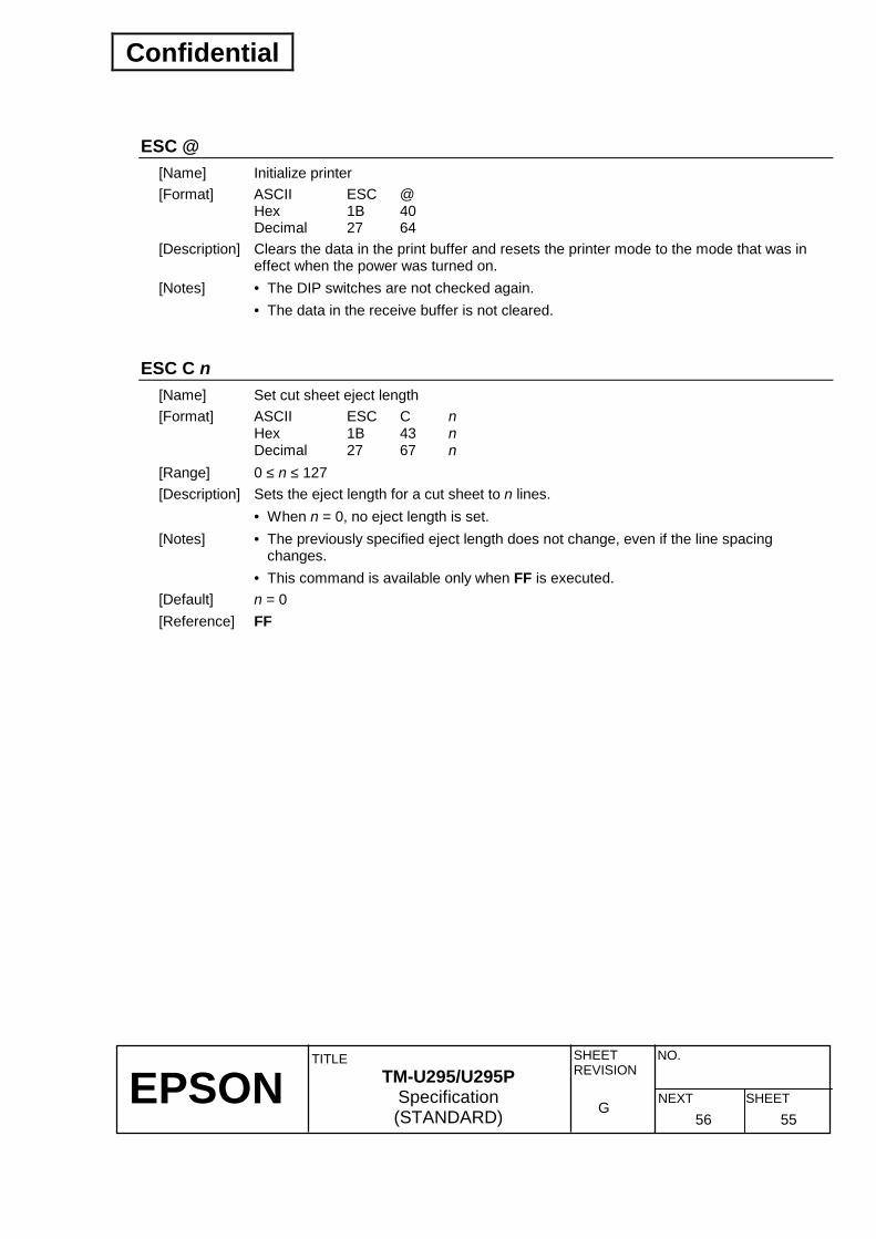
Confidential
EPSON
TITLE SHEET REVISION
NO.
SHEETNEXT G
TM-U295/U295P Specification (STANDARD) 56 55
ESC @ [Name] Initialize printer [Format] ASCII ESC @
Hex 1B 40 Decimal 27 64
[Description] Clears the data in the print buffer and resets the printer mode to the mode that was in effect when the power was turned on.
[Notes] • The DIP switches are not checked again. • The data in the receive buffer is not cleared.
ESC C n [Name] Set cut sheet eject length [Format] ASCII ESC C n
Hex 1B 43 n Decimal 27 67 n
[Range] 0 ≤ n ≤ 127 [Description] Sets the eject length for a cut sheet to n lines. • When n = 0, no eject length is set. [Notes] • The previously specified eject length does not change, even if the line spacing
changes. • This command is available only when FF is executed. [Default] n = 0 [Reference] FF

Confidential
EPSON
TITLE SHEET REVISION
NO.
SHEETNEXT G
TM-U295/U295P Specification (STANDARD) 57 56
ESC D n1...nk NUL [Name] Set horizontal tab positions [Format] ASCII ESC D n1...nk NUL
Hex 1B 44 n1...nk 00 Decimal 27 68 n1...nk 0
[Range] 1 ≤ n ≤ 255 0 ≤ k ≤ 32
[Description] Sets horizontal tab positions. • n specifies the number of columns present between the beginning of the line and the
position at which a horizontal table is to be set. n = tab column position - 1. If you want to set a tab at column 9, set n to 8. • k indicates the total number of horizontal tab positions to be set. • A horizontal tab position is set to a position expressed by “character width × n” from
the beginning of the line. The character width includes the right-side character spacing. In double-width mode, the character width is twice the width of normal characters. In page mode, the character width is also determined according to the double-width setting.
• [n] k, which indicates the set position, needs to be set in ascending order and <00>H must be entered at the end.
• ESC D NUL cancels all horizontal tab positions. An HT received after tabs are cleared is ignored.
[Notes] • When [n] k is less than or equal to the preceding value [n] k-1, horizontal tab setting is considered to have been completed. In this case, the subsequent data is processed as normal data.
• Up to 32 tab positions can be set. Data exceeding 32 tab positions is processed as normal data.
• If an HT is executed, attempts to move to any tab position outside the printable area will result in movement to a position only 1 dot outside the printable area.
• Once horizontal tab positions are specified, they do not change even if the character width is changed.
• The right-side character spacing is set independently in page mode and in standard mode. Therefore, the right-side character spacing is used to set horizontal tab positions.
[Default] The default tab positions are at intervals of 8 characters (columns 9, 17, 25, ...) for the 5 × 7 character font.
[Reference] Section 3.9.2, Page Mode Limitations

Confidential
EPSON
TITLE SHEET REVISION
NO.
SHEETNEXT G
TM-U295/U295P Specification (STANDARD) 58 57
ESC F n [Name] Set/cancel cut sheet reverse eject [Format] ASCII ESC F n
Hex 1B 46 n Decimal 27 70 n
[Range] 0 ≤ n ≤ 255 [Description] Sets or cancels the cut sheet reverse eject specified by FF.
When n = <∗∗∗∗∗∗∗ 1>B, reverse ejection is set. When n = <∗∗∗∗∗∗∗ 0>B, reverse ejection is canceled (forward ejection is set automatically).
[Default] n = 0 [Reference] FF
ESC J n [Name] Print and feed paper [Format] ASCII ESC J n
Hex 1B 4A n Decimal 27 74 n
[Range] 0 ≤ n ≤ 255 [Description] Prints the data in the print buffer and feeds the paper by n/60 inches (n × approximately
0.423 mm). [Notes] Sets the print position to the beginning of the line.
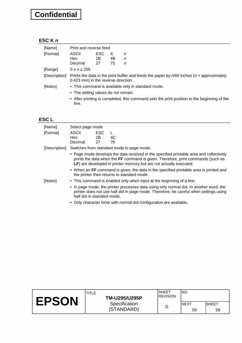
Confidential
EPSON
TITLE SHEET REVISION
NO.
SHEETNEXT G
TM-U295/U295P Specification (STANDARD) 59 58
ESC K n [Name] Print and reverse feed [Format] ASCII ESC K n
Hex 1B 4B n Decimal 27 75 n
[Range] 0 ≤ n ≤ 255 [Description] Prints the data in the print buffer and feeds the paper by n/60 inches (n × approximately
0.423 mm) in the reverse direction. [Notes] • This command is available only in standard mode. • The setting values do not remain. • After printing is completed, this command sets the print position to the beginning of the
line.
ESC L [Name] Select page mode [Format] ASCII ESC L
Hex 1B 4C Decimal 27 76
[Description] Switches from standard mode to page mode. • Page mode develops the data received in the specified printable area and collectively
prints the data when the FF command is given. Therefore, print commands (such as LF) are developed in printer memory but are not actually executed.
• When an FF command is given, the data in the specified printable area is printed and the printer then returns to standard mode.
[Notes] • This command is enabled only when input at the beginning of a line. • In page mode, the printer processes data using only normal dot. In another word, the
printer does not use half dot in page mode. Therefore, be careful when settings using half dot in standard mode.
• Only character fonts with normal dot configuration are available.

Confidential
EPSON
TITLE SHEET REVISION
NO.
SHEETNEXT G
TM-U295/U295P Specification (STANDARD) 60 59
• The following commands have two type of setting values, one is for standard mode,
the other is for page mode. ESC SP: Set right-side character spacing
ESC 2: Set the inital line spacing ESC 3: Set line spacing
• The following commands are ignored in page mode. ESC K: Print and reverse feed
ESC e: Print and reverse feed n lines ESC ∗∗∗∗ : Set double-density bit image. ESC q: Paper release
The following commands are settable but do not have any effect in page mode. • ESC (Upside-down printing mode on/off) • ESC ! (7 × 7 font mode on/off and underline mode on/off) • The commands are effective only in standard mode. • Use of ESC @ causes the printer to return to standard mode without carrying out
printing. [Default] Standard mode is selected. [Reference] FF Section 3.9.2, Page Mode Limitations Appendix D, Transmission Status Identification

Confidential
EPSON
TITLE SHEET REVISION
NO.
SHEETNEXT G
TM-U295/U295P Specification (STANDARD) 61 60
ESC R n [Name] Select an international character set [Format] ASCII ESC R n
Hex 1B 52 n Decimal 27 82 n
[Range] 0 ≤ n ≤ 10 [Description] Selects an international character set n from the following table:
n Country 0 U.S.A. 1 France 2 Germany 3 U.K. 4 Denmark I 5 Sweden 6 Italy 7 Spain 8 Japan 9 Norway 10 Denmark II
[Note] If n is outside of the specified range, this command is ignored. [Default] n = 0 [Reference] Section 3.2.3, International Character Set

Confidential
EPSON
TITLE SHEET REVISION
NO.
SHEETNEXT G
TM-U295/U295P Specification (STANDARD) 62 61
ESC T n [Name] Select print direction in page mode [Format] ASCII ESC T n
Hex 1B 54 n Decimal 27 84 n
[Range] 0 ≤ n ≤ 3, 48 ≤ n ≤ 51 [Description] Selects the print direction and starting position in page mode. n specifies the print direction and starting position as follows:
n Print Direction Starting Position 0, 48 Left to right Upper left (A in the figure) 1, 49 Bottom to top Lower left (B in the figure) 2, 50 Right to left Lower right (C in the figure) 3, 51 Top to bottom Upper right (D in the figure)
Pape
r fee
d di
rect
ion
Printable area
[Notes] • When the printing direction is changed, the printing direction and print starting position
for the data following are those specified by n. • This command is available only in page mode. • If n is out of the specified range, this command is ignored. [Default] n = 0

Confidential
EPSON
TITLE SHEET REVISION
NO.
SHEETNEXT G
TM-U295/U295P Specification (STANDARD) 63 62
ESC W xL xH yL yH dxL dxH dyL dyH [Name] Set printing area in page mode [Format] ASCII ESC W xL xH yL yH dxL dxH dyL dyH
Hex 1B 57 xL xH yL yH dxL dxH dyL dyH Decimal 27 87 xL xH yL yH dxL dxH dyL dyH
[Range] 0 ≤ xL ≤ 255, xH = 0, 0 ≤ yL ≤ 255, 0 ≤ yH ≤ 1, 0 ≤ dxL ≤ 255, dxH = 0 0 ≤ dyL ≤ 255, 0 ≤ dyH ≤ 1 Except dxL=dxH=0, or dyL=dyH=0
[Description] Sets the position and the size of the printing area. • Starting from the position (x0, y0) at the upper right, the length in the y direction is dy
dot and that in the x direction is dx dot. x0 = [(xL + xH × 256)] y0 = [(yL + yH × 256)]
dx = [(dxL + dxH × 256)] dy = [(dyL + dyH × 256)]
dy
dx
Printing area
(209 dots, 479 dpts)(X0+dx-1, Y+dy-1)
Printable area of paper used
(0, 0)
(0X, 0Y)
[Notes] • If the setting values exceed the printing area, it set to the maximum printing area
automatically, depending on the values from xL to dyH. • The maximum printing area in the x direction is 210 dots. • The maximum printing area in the y direction is 480 dots. • When the print data is buffered in the specified printing area, the length of the printing
area in both the horizontal and vertical direction should be 8 dots or more. • The printing area should accommodate to the size of the print sheet. • When starting point (x0, y0) is out of printable area, this command is not effective. • This command is available only in page mode. • This command is settable but does not have any effect in standard mode. [Default] xL = xH = yL = yH = 0 dxL = 210, dxH = 0, dyL = 224, dyH = 1 [Reference] CAN, ESC L, ESC T

Confidential
EPSON
TITLE SHEET REVISION
NO.
SHEETNEXT G
TM-U295/U295P Specification (STANDARD) 64 63
ESC c 3 n [Name] Select paper sensor(s) to output paper end signals [Format] ASCII ESC c 3 n
Hex 1B 63 33 n Decimal 27 99 51 n
[Range] 0 ≤ n ≤ 255 [Description] Selects the paper sensor(s) to output paper end signals. • Each bit of n is used as follows:
Bit Off/On Hex Decimal Function Off -- -- Undefined. 0 On -- -- Undefined. Off -- -- Undefined. 1 On -- -- Undefined. Off -- -- Undefined. 2 On -- -- Undefined. Off -- -- Undefined. 3 On -- -- Undefined. Off 00 0 TOF sensor disabled. 4 On 10 16 TOF sensor enabled. Off 00 0 BOF sensor disabled. 5 On 20 32 BOF sensor enabled. Off -- -- Undefined. 6 On -- -- Undefined. Off -- -- Undefined. 7 On -- -- Undefined.
[Notes] • It is possible to select multiple sensors to output signals. Then, if any of the sensors
detects a paper end, the paper end signals is output. • This command is available only with a parallel interface model and is ignored with a
serial interface model. [Default] n = 0
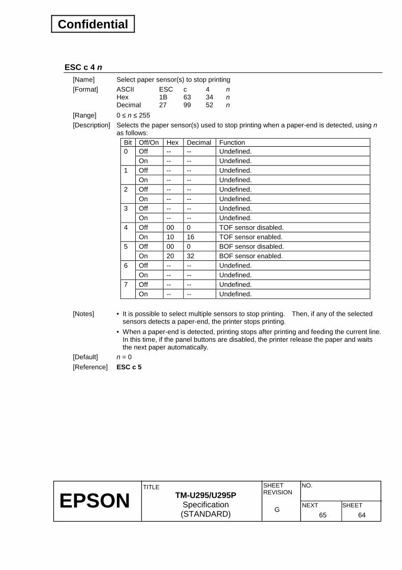
Confidential
EPSON
TITLE SHEET REVISION
NO.
SHEETNEXT G
TM-U295/U295P Specification (STANDARD) 65 64
ESC c 4 n [Name] Select paper sensor(s) to stop printing [Format] ASCII ESC c 4 n
Hex 1B 63 34 n Decimal 27 99 52 n
[Range] 0 ≤ n ≤ 255 [Description] Selects the paper sensor(s) used to stop printing when a paper-end is detected, using n
as follows: Bit Off/On Hex Decimal Function
Off -- -- Undefined. 0 On -- -- Undefined. Off -- -- Undefined. 1 On -- -- Undefined. Off -- -- Undefined. 2 On -- -- Undefined. Off -- -- Undefined. 3 On -- -- Undefined. Off 00 0 TOF sensor disabled. 4 On 10 16 TOF sensor enabled. Off 00 0 BOF sensor disabled. 5 On 20 32 BOF sensor enabled. Off -- -- Undefined. 6 On -- -- Undefined. Off -- -- Undefined. 7 On -- -- Undefined.
[Notes] • It is possible to select multiple sensors to stop printing. Then, if any of the selected
sensors detects a paper-end, the printer stops printing. • When a paper-end is detected, printing stops after printing and feeding the current line.
In this time, if the panel buttons are disabled, the printer release the paper and waits the next paper automatically.
[Default] n = 0 [Reference] ESC c 5

Confidential
EPSON
TITLE SHEET REVISION
NO.
SHEETNEXT G
TM-U295/U295P Specification (STANDARD) 66 65
ESC c 5 n [Name] Enable/disable panel buttons [Format] ASCII ESC c 5 n
Hex 1B 63 35 n Decimal 27 99 53 n
[Range] 0 ≤ n ≤ 255 [Description] Enables or disables the panel buttons. • Only the LSB of n is effective.
When n = <∗∗∗∗∗∗∗ 0>B, the panel switches are enabled. When n = <∗∗∗∗∗∗∗ 1>B, the panel switches are disabled.
[Note] When the panel buttons are disabled, none of them are usable. [Default] n = 0
ESC d n [Name] Print and feed n lines [Format] ASCII ESC d n
Hex 1B 64 n Decimal 27 100 n
[Range] 0 ≤ n ≤ 255 [Description] Prints the data in the print buffer and feeds n lines. [Notes] • This command sets the print starting position to the beginning of the line. • This command does not affect the line spacing set by ESC 2 or ESC 3. [Reference] ESC 2, ESC 3

Confidential
EPSON
TITLE SHEET REVISION
NO.
SHEETNEXT G
TM-U295/U295P Specification (STANDARD) 67 66
ESC e n [Name] Print and reverse feed n lines [Format] ASCII ESC e n
Hex 1B 65 n Decimal 27 101 n
[Range] 0 ≤ n ≤ 255 [Description] Prints the data in the print buffer and feeds n lines in the reverse direction. [Notes] • This command is available only in standard mode. • This command sets the print position to the beginning of the line. • The setting values do not remain.
ESC f t1 t2 [Name] Set cut sheet wait time [Format] ASCII ESC f t1 t2
Hex 1B 66 t1 t2 Decimal 27 102 t1 t2
[Range] t1 = 0 0 ≤ t2 ≤ 64 [Description] Sets the time during which the printer waits for a cut sheet to be inserted and the time
from insertion of the sheet to the start of printing. • The time during which the printer waits for a cut sheet to be inserted is unlimited. • The printer starts operation [t2 × 0.1] seconds after insertion of the sheet is detected. [Notes] • When either t1 or t2 is out of the specified range, this command does not change the
previously set wait time. [Default] t1 = 0, t2 = 10

Confidential
EPSON
TITLE SHEET REVISION
NO.
SHEETNEXT G
TM-U295/U295P Specification (STANDARD) 68 67
ESC p m t1 t2 [Name] Generate pulse [Format] ASCII ESC p m t1 t2
Hex 1B 70 m t1 t2 Decimal 27 112 m t1 t2
[Range] m = 0, 1, 48, 49 0 ≤ t1 ≤ 255 0 ≤ t2 ≤ 255
[Description] Outputs the pulse specified by t1 and t2 to connector pin m. m Connector pin 0, 48 Drawer kick-out connector pin 2 0, 49 Drawer kick-out connector pin 5
• The pulse ON time is [t1 × 2 ms] and the OFF time is [t2 × 2 ms]. [Notes] • If the m is out of the specified range, this command is ignored, and the data following
is processed as normal data. [Reference] Section 2.2.3, Drawer kick-out Connector Appendix C, Notes on Drawer Kick-out Connector
Confidential
EPSON
TITLE SHEET REVISION
NO.
SHEETNEXT G
TM-U295/U295P Specification (STANDARD) 69 68
ESC q [Name] Paper release [Format] ASCII ESC q
Hex 1B 71 Decimal 27 113
[Description] Releases the paper. [Notes] • When the panel button is disabled and the specified paper sensor detects a
paper-end, the printer releases the paper, regardless of this command. • This command is available only in standard mode. [Reference] ESC c 4, ESC c 5
ESC t n [Name] Select character code table [Format] ASCII ESC t n
Hex 1B 74 n Decimal 27 116 n
[Range] 0 ≤ n ≤ 2‚ n = 19 [Description] Selects a page n from the character code table. The value of n represents a page from the character code tables, as follows:
n Character type 0 PC437 (U.S.A., Standard Europe) 1 Katakana 2 PC850 (Multilingual) 19 PC858 (Euro)
[Note] If n is out of the specified range, this command is ignored. [Default] n = 0 [Reference] Section 3.2, Character Code Tables

Confidential
EPSON
TITLE SHEET REVISION
NO.
SHEETNEXT G
TM-U295/U295P Specification (STANDARD) 70 69
ESC u n [Name] Transmit peripheral device status [Format] ASCII ESC u n
Hex 1B 75 n Decimal 27 117 n
[Range] n = 0, 48 [Description] Transmits one status byte for a peripheral device to the connector pin
specified by n, as follows: n Connector pin 0, 48 Drawer kick-out connector pin 3
[Notes] • Peripheral device status data which can be transmitted are shown in the table below. • Bit 0 is always set to “1” if no connection is made to the connector. • When DTR/DSR control is selected, the printer transmits only 1 byte after confirming
that the host is ready to receive data (DSR signal is SPACE). If the host computer is not ready to receive data (DSR signal is MARK), the printer waits until the host is ready. When XON/XOFF control is selected, the printer transmits only 1 byte without confirming the status of the DSR signal.
• Since this command is stored in the receive buffer and then executed during normal command process, there may be a time lag between command reception and status transmission, depending on the receive buffer status.
• When Automatic Status Back (ASB) is enabled using GS a, the status transmitted by this command must be differentiated from the ASB status. For a detailed description, refer to Appendix D.
• If n is out of the specified range, this command is ignored.
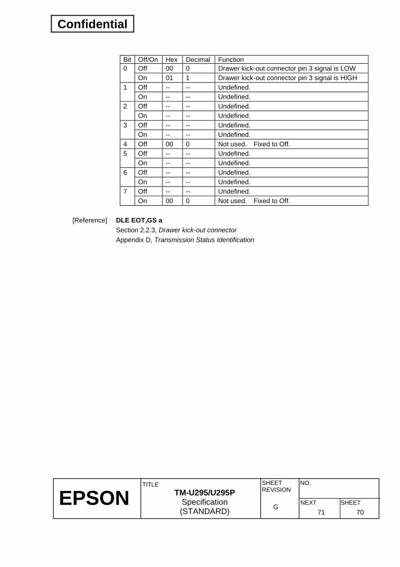
Confidential
EPSON
TITLE SHEET REVISION
NO.
SHEETNEXT G
TM-U295/U295P Specification (STANDARD) 71 70
Bit Off/On Hex Decimal Function
Off 00 0 Drawer kick-out connector pin 3 signal is LOW 0 On 01 1 Drawer kick-out connector pin 3 signal is HIGH Off -- -- Undefined. 1 On -- -- Undefined. Off -- -- Undefined. 2 On -- -- Undefined. Off -- -- Undefined. 3 On -- -- Undefined.
4 Off 00 0 Not used. Fixed to Off. Off -- -- Undefined. 5 On -- -- Undefined. Off -- -- Undefined. 6 On -- -- Undefined. Off -- -- Undefined. 7 On 00 0 Not used. Fixed to Off.
[Reference] DLE EOT,GS a Section 2.2.3, Drawer kick-out connector Appendix D, Transmission Status Identification
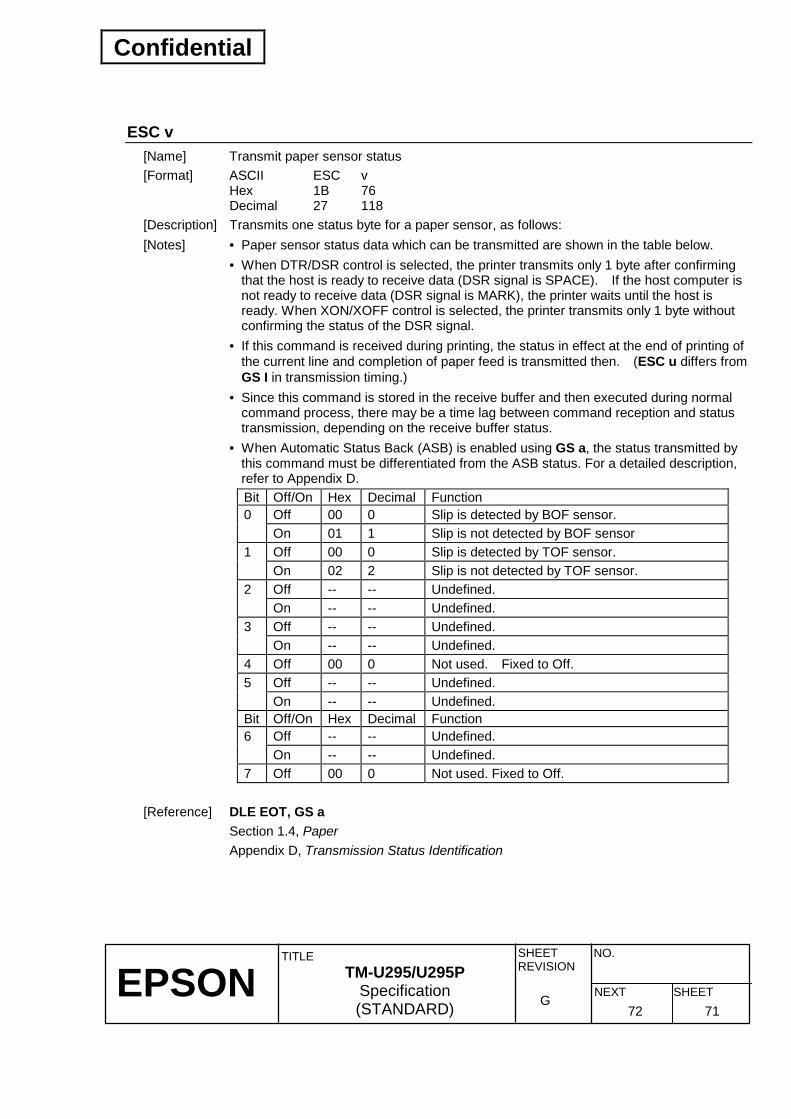
Confidential
EPSON
TITLE SHEET REVISION
NO.
SHEETNEXT G
TM-U295/U295P Specification (STANDARD) 72 71
ESC v [Name] Transmit paper sensor status [Format] ASCII ESC v
Hex 1B 76 Decimal 27 118
[Description] Transmits one status byte for a paper sensor, as follows: [Notes] • Paper sensor status data which can be transmitted are shown in the table below. • When DTR/DSR control is selected, the printer transmits only 1 byte after confirming
that the host is ready to receive data (DSR signal is SPACE). If the host computer is not ready to receive data (DSR signal is MARK), the printer waits until the host is ready. When XON/XOFF control is selected, the printer transmits only 1 byte without confirming the status of the DSR signal.
• If this command is received during printing, the status in effect at the end of printing of the current line and completion of paper feed is transmitted then. (ESC u differs from GS I in transmission timing.)
• Since this command is stored in the receive buffer and then executed during normal command process, there may be a time lag between command reception and status transmission, depending on the receive buffer status.
• When Automatic Status Back (ASB) is enabled using GS a, the status transmitted by this command must be differentiated from the ASB status. For a detailed description, refer to Appendix D. Bit Off/On Hex Decimal Function
Off 00 0 Slip is detected by BOF sensor. 0 On 01 1 Slip is not detected by BOF sensor Off 00 0 Slip is detected by TOF sensor. 1 On 02 2 Slip is not detected by TOF sensor. Off -- -- Undefined. 2 On -- -- Undefined. Off -- -- Undefined. 3 On -- -- Undefined.
4 Off 00 0 Not used. Fixed to Off. Off -- -- Undefined. 5 On -- -- Undefined.
Bit Off/On Hex Decimal Function Off -- -- Undefined. 6 On -- -- Undefined.
7 Off 00 0 Not used. Fixed to Off. [Reference] DLE EOT, GS a Section 1.4, Paper Appendix D, Transmission Status Identification
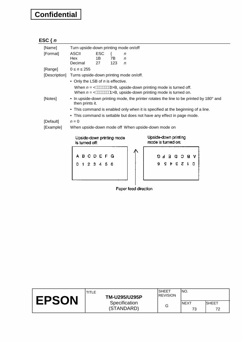
Confidential
EPSON
TITLE SHEET REVISION
NO.
SHEETNEXT G
TM-U295/U295P Specification (STANDARD) 73 72
ESC n [Name] Turn upside-down printing mode on/off [Format] ASCII ESC n
Hex 1B 7B n Decimal 27 123 n
[Range] 0 ≤ n ≤ 255 [Description] Turns upside-down printing mode on/off. • Only the LSB of n is effective.
When n = <∗∗∗∗∗∗∗ 0>B, upside-down printing mode is turned off. When n = <∗∗∗∗∗∗∗ 1>B, upside-down printing mode is turned on.
[Notes] • In upside-down printing mode, the printer rotates the line to be printed by 180° and then prints it.
• This command is enabled only when it is specified at the beginning of a line. • This command is settable but does not have any effect in page mode. [Default] n = 0 [Example] When upside-down mode off When upside-down mode on

Confidential
EPSON
TITLE SHEET REVISION
NO.
SHEETNEXT G
TM-U295/U295P Specification (STANDARD) 74 73
GS I n [Name] Transmit printer ID [Format] ASCII GS I n
Hex 1D 49 n Decimal 29 73 n
[Range] 1 ≤ n ≤ 3, 49 ≤ n ≤ 51 [Description] Transmits the printer ID specified by n as follows:
n Print Direction Specification ID (Hex) 1, 49 Printer model ID TM-295/TM-295P 02H 2, 50 Type ID Refer to table below 3, 51 ROM version ID Depends on ROM version ∗∗
[Notes] • When DTR/DSR control is selected, the printer transmits only 1 byte after confirming
that the host is ready to receive data (DSR signal is SPACE). If the host computer is not ready to receive data (DSR signal is MARK), the printer waits until the host is ready. When XON/XOFF control is selected, the printer transmits only 1 byte without confirming the status of the DSR signal.
• Since this command is stored in the receive buffer and then executed during normal command process, there may be a time lag between command reception and status transmission, depending on the receive buffer status.
• When Automatic Status Back (ASB) is enabled using GS a, the status transmitted by this command must be differentiated from the ASB status. For a detailed description, refer to Appendix D.
• The ROM version may change as different versions are released. • If n is out of the specified range, this command is ignored.

Confidential
EPSON
TITLE SHEET REVISION
NO.
SHEETNEXT G
TM-U295/U295P Specification (STANDARD) 75 74
n = 2: Type ID
Bit Off/On Hex Decimal Function 0 Off 00 0 Two-byte character code not supported. 1 Off 00 0 Auto-cutter not equipped.
Off -- -- Undefined. 2 On -- -- Undefined. Off -- -- Undefined. 3 On -- -- Undefined.
4 Off 00 0 Not used. Fixed to Off. Off -- -- Undefined. 5 On -- -- Undefined. Off -- -- Undefined. 6 On -- -- Undefined.
7 Off 00 0 Not used. Fixed to Off. [Reference] Section 3.3.3, DIP switches: Appendix D, Transmission Status Identification
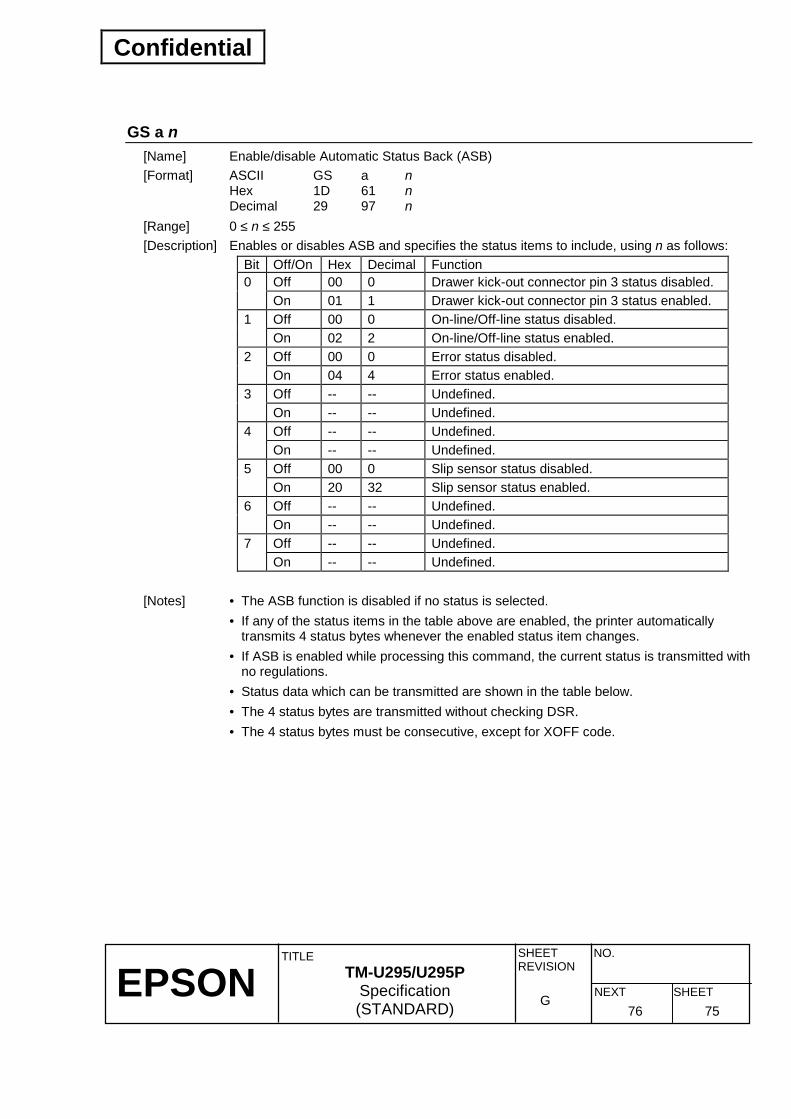
Confidential
EPSON
TITLE SHEET REVISION
NO.
SHEETNEXT G
TM-U295/U295P Specification (STANDARD) 76 75
GS a n [Name] Enable/disable Automatic Status Back (ASB) [Format] ASCII GS a n
Hex 1D 61 n Decimal 29 97 n
[Range] 0 ≤ n ≤ 255 [Description] Enables or disables ASB and specifies the status items to include, using n as follows:
Bit Off/On Hex Decimal Function Off 00 0 Drawer kick-out connector pin 3 status disabled. 0 On 01 1 Drawer kick-out connector pin 3 status enabled. Off 00 0 On-line/Off-line status disabled. 1 On 02 2 On-line/Off-line status enabled. Off 00 0 Error status disabled. 2 On 04 4 Error status enabled. Off -- -- Undefined. 3 On -- -- Undefined. Off -- -- Undefined. 4 On -- -- Undefined. Off 00 0 Slip sensor status disabled. 5 On 20 32 Slip sensor status enabled. Off -- -- Undefined. 6 On -- -- Undefined. Off -- -- Undefined. 7 On -- -- Undefined.
[Notes] • The ASB function is disabled if no status is selected. • If any of the status items in the table above are enabled, the printer automatically
transmits 4 status bytes whenever the enabled status item changes. • If ASB is enabled while processing this command, the current status is transmitted with
no regulations. • Status data which can be transmitted are shown in the table below. • The 4 status bytes are transmitted without checking DSR. • The 4 status bytes must be consecutive, except for XOFF code.

Confidential
EPSON
TITLE SHEET REVISION
NO.
SHEETNEXT G
TM-U295/U295P Specification (STANDARD) 77 76
• Since this command is stored in the receive buffer and then executed during normal
command process, there may be a time lag between command reception and status transmission, depending on the receive buffer status.
• When the printer disabled is selected using ESC =, this command is disabled, but the ASB is always enabled.
• When any of DLE EOT, ESC u, ESC v, or GS I is used, the status transmitted by these commands and the ASB status must be differentiated by using the table in Appendix D.
➀ First byte (printer information): Bit Off/On Hex Decimal Status for ASB 0 Off 00 0 Not used. Fixed to Off. 1 Off 00 0 Not used. Fixed to Off.
Off 00 0 Drawer kick-out connector pin 3 is LOW. 2 On 04 4 Drawer kick-out connector pin 3 is HIGH. Off 00 0 On-line. 3 On 08 8 Off-line.
4 On 10 16 Not used. Fixed to On. 5 Off -- -- Undefined.
Off 00 0 Paper is not being fed by the paper feed button. 6 On 40 64 Paper is being fed by the paper feed button.
7 Off 00 0 Not used. Fixed to Off.
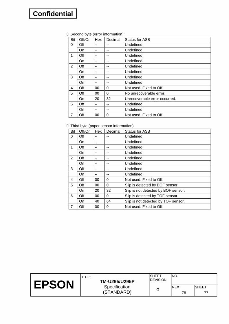
Confidential
EPSON
TITLE SHEET REVISION
NO.
SHEETNEXT G
TM-U295/U295P Specification (STANDARD) 78 77
➁ Second byte (error information):
Bit Off/On Hex Decimal Status for ASB Off -- -- Undefined. 0 On -- -- Undefined. Off -- -- Undefined. 1 On -- -- Undefined. Off -- -- Undefined. 2 On -- -- Undefined. Off -- -- Undefined. 3 On -- -- Undefined.
4 Off 00 0 Not used. Fixed to Off. Off 00 0 No unrecoverable error. 5 On 20 32 Unrecoverable error occurred. Off -- -- Undefined. 6 On -- -- Undefined.
7 Off 00 0 Not used. Fixed to Off. ➂ Third byte (paper sensor information):
Bit Off/On Hex Decimal Status for ASB Off -- -- Undefined. 0 On -- -- Undefined. Off -- -- Undefined. 1 On -- -- Undefined. Off -- -- Undefined. 2 On -- -- Undefined. Off -- -- Undefined. 3 On -- -- Undefined.
4 Off 00 0 Not used. Fixed to Off. Off 00 0 Slip is detected by BOF sensor. 5 On 20 32 Slip is not detected by BOF sensor. Off 00 0 Slip is detected by TOF sensor. 6 On 40 64 Slip is not detected by TOF sensor.
7 Off 00 0 Not used. Fixed to Off.
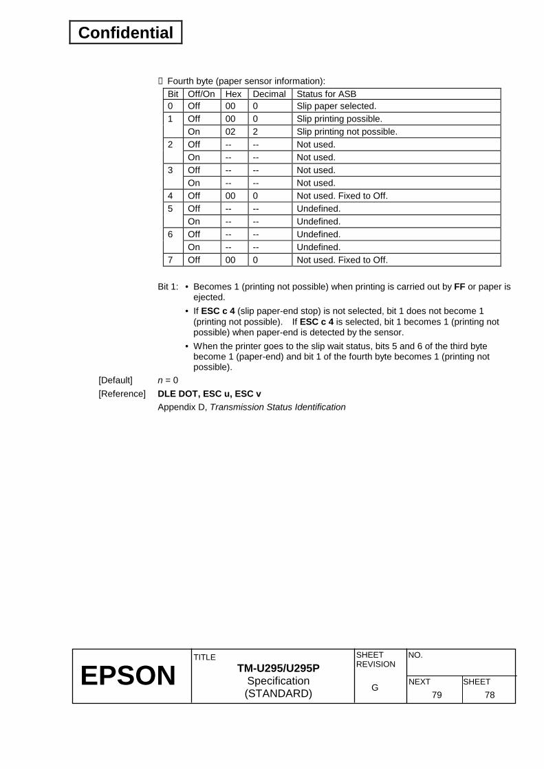
Confidential
EPSON
TITLE SHEET REVISION
NO.
SHEETNEXT G
TM-U295/U295P Specification (STANDARD) 79 78
➃ Fourth byte (paper sensor information):
Bit Off/On Hex Decimal Status for ASB 0 Off 00 0 Slip paper selected.
Off 00 0 Slip printing possible. 1 On 02 2 Slip printing not possible. Off -- -- Not used. 2 On -- -- Not used. Off -- -- Not used. 3 On -- -- Not used.
4 Off 00 0 Not used. Fixed to Off. Off -- -- Undefined. 5 On -- -- Undefined. Off -- -- Undefined. 6 On -- -- Undefined.
7 Off 00 0 Not used. Fixed to Off. Bit 1: • Becomes 1 (printing not possible) when printing is carried out by FF or paper is
ejected. • If ESC c 4 (slip paper-end stop) is not selected, bit 1 does not become 1
(printing not possible). If ESC c 4 is selected, bit 1 becomes 1 (printing not possible) when paper-end is detected by the sensor.
• When the printer goes to the slip wait status, bits 5 and 6 of the third byte become 1 (paper-end) and bit 1 of the fourth byte becomes 1 (printing not possible).
[Default] n = 0 [Reference] DLE DOT, ESC u, ESC v Appendix D, Transmission Status Identification

Confidential
EPSON
TITLE SHEET REVISION
NO.
SHEETNEXT G
TM-U295/U295P Specification (STANDARD) 80 79
GS r n [Name] Transmit status [Format] ASCII GS r n
Hex 1D 72 n Decimal 29 114 n
[Range] 1 ≤ n ≤ 2, 49 ≤ n ≤ 50 [Description] Transmits the status specified by n as follows:
n = 1, 49: Transmits paper sensor status (same as ESC v) n = 2, 50: Transmits drawer kick-out connector status (same as ESC u 0)
[Notes] • Status data which can be transmitted are shown below and in the table of the next section.
• When DTR/DSR control is selected, the printer transmits only 1 byte after confirming that the host is ready to receive data (DSR signal is SPACE). If the host computer is not ready to receive data (DSR signal is MARK), the printer waits until the host is ready. When XON/XOFF control is selected, the printer transmits only 1 byte without confirming the status of the DSR signal.
• Since this command is stored in the receive buffer and then executed during normal command process, there may be a time lag between command reception and status transmission, depending on the receive buffer status.
• When Automatic Status Back (ASB) is enabled using GS a, the status transmitted by this command must be differentiated from the ASB status. For a detailed description, refer to Appendix D.
• If n is out of the specified range, this command is ignored.

Confidential
EPSON
TITLE SHEET REVISION
NO.
SHEETNEXT G
TM-U295/U295P Specification (STANDARD) 81 80
Paper sensor status (n = 1, 49):
Bit Off/On Hex Decimal Status for ASB Off 00 0 Slip is detected by BOF sensor. 0 On 01 1 Slip is not detected by BOF sensor. Off 00 0 Slip is detected by TOF sensor. 1 On 02 2 Slip is not detected by TOF sensor. Off -- -- Undefined. 2 On -- -- Undefined. Off -- -- Undefined. 3 On -- -- Undefined.
4 Off 00 0 Not used. Fixed to Off. Off -- -- Undefined. 5 On -- -- Undefined. Off -- -- Undefined. 6 On -- -- Undefined.
7 Off 00 0 Not used. Fixed to Off. Drawer kick-out connector status (n = 2, 50):
Bit Off/On Hex Decimal Status for ASB Off 00 0 Drawer kick-out connector pin 3 is LOW. 0 On 01 1 Drawer kick-out connector pin 3 is HIGH. Off -- -- Undefined. 1 On -- -- Undefined. Off -- -- Undefined. 2 On -- -- Undefined. Off -- -- Undefined. 3 On -- -- Undefined.
4 Off 00 0 Not used. Fixed to Off. Off -- -- Undefined. 5 On -- -- Undefined. Off -- -- Undefined. 6 On -- -- Undefined.
7 Off 00 0 Not used. Fixed to Off. [Reference] DLE EOT, ESC u, ESC v, GS a Appendix D, Transmission Status Identification
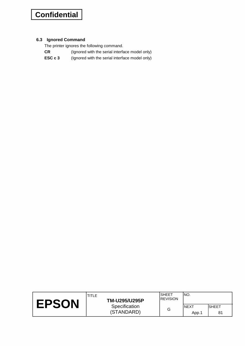
Confidential
EPSON
TITLE SHEET REVISION
NO.
SHEETNEXT G
TM-U295/U295P Specification (STANDARD) 82 81
6.3 Ignored Command The printer ignores the following command. CR (Ignored with the serial interface model only) ESC c 3 (Ignored with the serial interface model only)
App.1
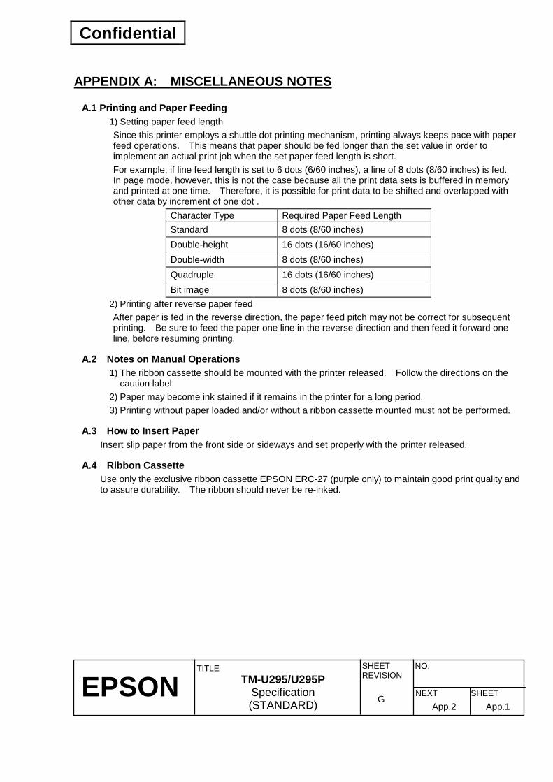
Confidential
EPSON
TITLE SHEET REVISION
NO.
SHEETNEXT G
TM-U295/U295P Specification (STANDARD) App.1App.2
APPENDIX A: MISCELLANEOUS NOTES
A.1 Printing and Paper Feeding 1) Setting paper feed length Since this printer employs a shuttle dot printing mechanism, printing always keeps pace with paper feed operations. This means that paper should be fed longer than the set value in order to implement an actual print job when the set paper feed length is short. For example, if line feed length is set to 6 dots (6/60 inches), a line of 8 dots (8/60 inches) is fed. In page mode, however, this is not the case because all the print data sets is buffered in memory and printed at one time. Therefore, it is possible for print data to be shifted and overlapped with other data by increment of one dot .
Character Type Required Paper Feed Length Standard 8 dots (8/60 inches) Double-height 16 dots (16/60 inches) Double-width 8 dots (8/60 inches) Quadruple 16 dots (16/60 inches) Bit image 8 dots (8/60 inches)
2) Printing after reverse paper feed After paper is fed in the reverse direction, the paper feed pitch may not be correct for subsequent printing. Be sure to feed the paper one line in the reverse direction and then feed it forward one line, before resuming printing.
A.2 Notes on Manual Operations 1) The ribbon cassette should be mounted with the printer released. Follow the directions on the
caution label. 2) Paper may become ink stained if it remains in the printer for a long period. 3) Printing without paper loaded and/or without a ribbon cassette mounted must not be performed.
A.3 How to Insert Paper Insert slip paper from the front side or sideways and set properly with the printer released.
A.4 Ribbon Cassette Use only the exclusive ribbon cassette EPSON ERC-27 (purple only) to maintain good print quality and to assure durability. The ribbon should never be re-inked.

Confidential
EPSON
TITLE SHEET REVISION
NO.
SHEETNEXT G
TM-U295/U295P Specification (STANDARD) App.2App.3
APPENDIX B: PRINT DUTY Printing should be executed according to the print duty shown below.
1) Character printing The average number of dots printed per second (N) should be within the range shown in the figure below.
Drive Voltage: E(V)
At 50°C
At 0 to 25°CAllowable Duty:N (dots/sec. entire print head)
1400
1000
600
20021.6 24 26.4
1127
700
1218
756
1173
728
Figure B.1 Print Duty Example: Alphanumeric character full column printing (at 24 VDC)
Average number of dots per character: Approximately 14 Number of printable columns per line: 35 Mean printing speed: Approximately 2.1 lines per second Print duty = 14 × 35 × 2.1 = 1029 < 1173
Therefore, the alphanumeric character full-column printing is possible under the room temperature. If specific wires are to be preferentially used, refer to the print duty shown below.
Number of Print Drive Solenoids
Allowable Duty:N (dots/sec./Solenoid)at 0 to 25°C
1 2 3 4 5 6 70
100
200
300231
161
Figure B.2 Print Duty when Specific Wires are Preferentially Used

Confidential
EPSON
TITLE SHEET REVISION
NO.
SHEETNEXT G
TM-U295/U295P Specification (STANDARD) App.3App.4
2) Continuous printing
Each print solenoid can be used continuously up to 5400 dots. After energizing, however, the print solenoid must not be used for more than twice the period of energizing time to prepare the next printing.
Example 2: Continuous solid printing (when the bit image using continuous FFH is printed) Number of dots in the horizontal direction/solenoid: 30 Number of dots/lines/solenoid: 30 × 8 = 240 Maximum number of lines for continuous solid printing = 5400/240 = approximately 22
Therefore, continuous solid printing of 22 lines is possible. In this case, the print solenoid must not be used for [2 × 22 lines/2.1 = 21 second] before next printing.
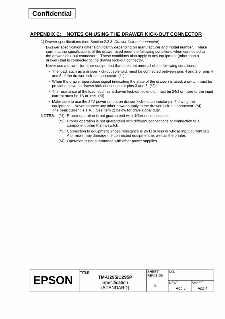
Confidential
EPSON
TITLE SHEET REVISION
NO.
SHEETNEXT G
TM-U295/U295P Specification (STANDARD) App.4App.5
APPENDIX C: NOTES ON USING THE DRAWER KICK-OUT CONNECTOR
1) Drawer specifications (see Section 2.2.3, Drawer kick-out connector) Dwawer specifications differ significantly depending on manufacturer and model number. Make sure that the specifications of the drawer used meet the following conditions when connected to the drawer kick-out connector. These conditions also apply to any equipment (other than a drawer) that is connected to the drawer kick-out connector. Never use a drawer (or other equipment) that does not meet all of the following conditions:
• The load, such as a drawer kick-out solenoid, must be connected between pins 4 and 2 or pins 4 and 5 of the drawer kick-out connector. (*1)
• When the drawer open/close signal (indicating the state of the drawer) is used, a switch must be provided between drawer kick-out connector pins 3 and 6. (*2)
• The resistance of the load, such as a drawer kick-out solenoid, must be 24Ω or more or the input current must be 1A or less. (*3)
• Make sure to use the 24V power output on drawer kick-out connector pin 4 driving the equipment. Never connect any other power supply to the drawer kick-out connector. (*4) The peak current is 1 A. See item 2) below for drive signal duty.
NOTES: (*1): Proper operation is not guaranteed with different connections. (*2): Proper operation is not guaranteed with different connections or connection to a
component other than a switch. (*3): Connection to equipment whose resistance is 24 Ω or less or whose input current is 1
A or more may damage the connected equipment as well as the printer. (*4): Operation is not guaranteed with other power supplies.

Confidential
EPSON
TITLE SHEET REVISION
NO.
SHEETNEXT G
TM-U295/U295P Specification (STANDARD) App.5App.6
APPENDIX D: TRANSMISSION STATUS IDENTIFICATION The values of specific bits are fixed in the status information transmitted by the printer, so that the status bytes of commands can be identified. The user can therefore confirm the command to which the status belongs, as shown in the following table. When using Auto Status Back (ASB), however, process the consecutive three-byte code (except for XOFF) as ASB data after confirming the first byte of the ASB. Otherwise, the status transmitted by using the command and the status of the second and following bytes of the ASB cannot be differentiated.
Command Status Reply ESC u <0∗∗ 0∗∗∗∗ >B ESC v <0∗∗ 0∗∗∗∗ >B GS I <0∗∗ 0∗∗∗∗ >B GS r <0∗∗ 0∗∗∗∗ >B XON <00010001>B XOFF <00010011>B DLE EOT <0∗∗ 1∗∗ 10>B ASB (1st byte) <0∗∗ 1∗∗ 00>B ASB (2nd byte - 4th byte) <0∗∗ 0∗∗∗∗ >B

Confidential
EPSON
TITLE SHEET REVISION
NO.
SHEETNEXT G
TM-U295/U295P Specification (STANDARD) App.6App.7
APPENDIX E: EXAMPLE PRINTING IN PAGE MODE Example use of page mode is described in this appendix. A typical procedure for transmitting commands in page mode is as follows:
➀ Transmit ESC L to enter page mode. ➁ Specify the printable area using ESC W. ➂ Specify the printing direction using ESC T. ➃ Transmit the print data. ➄ Collectively print the data by sending an FF. ➅ After printing, the printer automatically returns to standard mode.
Example 1: Sample program in BASIC (assumes transmission to the printer is already possible with file #1 open)
100 PRINT #1,CHR$(&H1B);"L"; 110 PRINT #1,CHR$(&H1B);"W";CHR$(0);CHR$(0);CHR$(0);CHR$(0); 120 PRINT #1,CHR$(100);CHR$(0);CHR$(100);CHR$(0); 130 PRINT #1,CHR$(&H1B);"T";CHR$(0); 140 PRINT #1,"Page mode lesson TEST 1" 150 PRINT #1,CHR$(&HC);
In the program for Example 1, a printable area of 100 × 100 dots starting at (0. 0) is set, and characters are printed on the first line of the area as shown in Figure E.1.1 below.
Figure E.1.1 Page Mode Example 1

Confidential
EPSON
TITLE SHEET REVISION
NO.
SHEETNEXT G
TM-U295/U295P Specification (STANDARD) App.7App.8
Note that a line feed was inserted between “lesson” and “TEST 1” in Figure E.1.1. This line feed was inserted automatically because there was no room for the blank “” following the word “lesson” within the horizontal range of the 100 × 100 printing area. The feed amount here is that specified by ESC 3. Any number of printing areas can be specified before the FF is executed. If any printing areas overlap, however, the logical sum of the logical sum of the data written to the overlapping portions is used for the final printing. It is possible to erase a portion of the data that is already developed. Using ESC W, specify a printing area consisting of only the section to be erased, then use CAN to erase the data. Note that all the data existing in the specified printing area is erased, even if it is just a portion of a character.
Example 2: Sample program in BASIC 100 PRINT #1,CHR$(&H1B);"L"; 110 PRINT #1,CHR$(&H1B);"W";CHR$(0);CHR$(0);CHR$(0);CHR$(0); 120 PRINT #1,CHR$(100);CHR$(0);CHR$(100);CHR$(0); 130 PRINT #1,CHR$(&H1B);"T";CHR$(0); 140 PRINT #1,"Page mode lesson 2 CAN command" 150 PRINT #1,"ABCDEFGHIJKLMNOPQRST1234567890" 160 PRINT #1,CHR$(&HC);
This example works as follows: First, transmit ESC L to switch to page mode (line no.100). Then use ESC W to send 8 arguments, from xL to dyH to specify the printing area. To specify a printing area of 100 dots in the x direction and 100 dots in the y direction, starting from the origin (0, 0), the arguments are transmitted in the order of 0, 0, 0, 0, 100, 0, 100, 0 (line nos. 110 and 120). In addition, the printing direction is specified as 0 by using ESC T (line no.130). After these items are specified, the print data “Page mode lesson 2 CAN command” and “ABCDEFGHIJKLMNOPQRST 1234567890” are transmitted (line no. 150). By sending FF (line no.160), the printout shown in Figure E.1.2 is produced.

Confidential
EPSON
TITLE SHEET REVISION
NO.
SHEETNEXT G
TM-U295/U295P Specification (STANDARD) App.8App.9
Figure E.1.2 Page Mode Example 2 If the program listed below is included before the FF is transmitted, a portion of the data will be deleted:
160 PRINT #1,CHR$(&H1B);"W";CHR$(36);CHR$(0);CHR$(20);CHR$(0); 170 PRINT #1,CHR$(18);CHR$(0);CHR$(10);CHR$(0); 180 PRINT #1,CHR$(&H18); 190 PRINT #1,CHR$(&HC);
If the above program is included, character string “GHI” is deleted, resulting in the printout shown in Figure E.1.3. When an area is deleted with CAN, the deleted part is left blank.
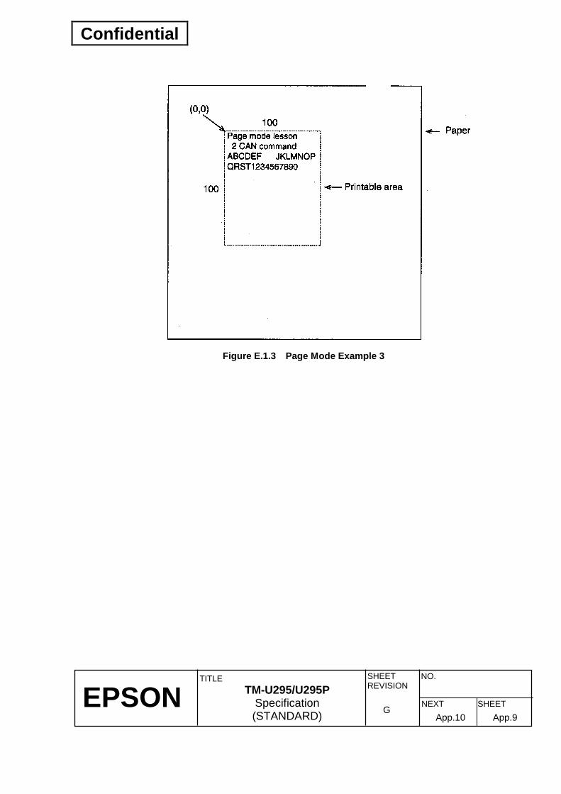
Confidential
EPSON
TITLE SHEET REVISION
NO.
SHEETNEXT G
TM-U295/U295P Specification (STANDARD) App.9App.10
Figure E.1.3 Page Mode Example 3
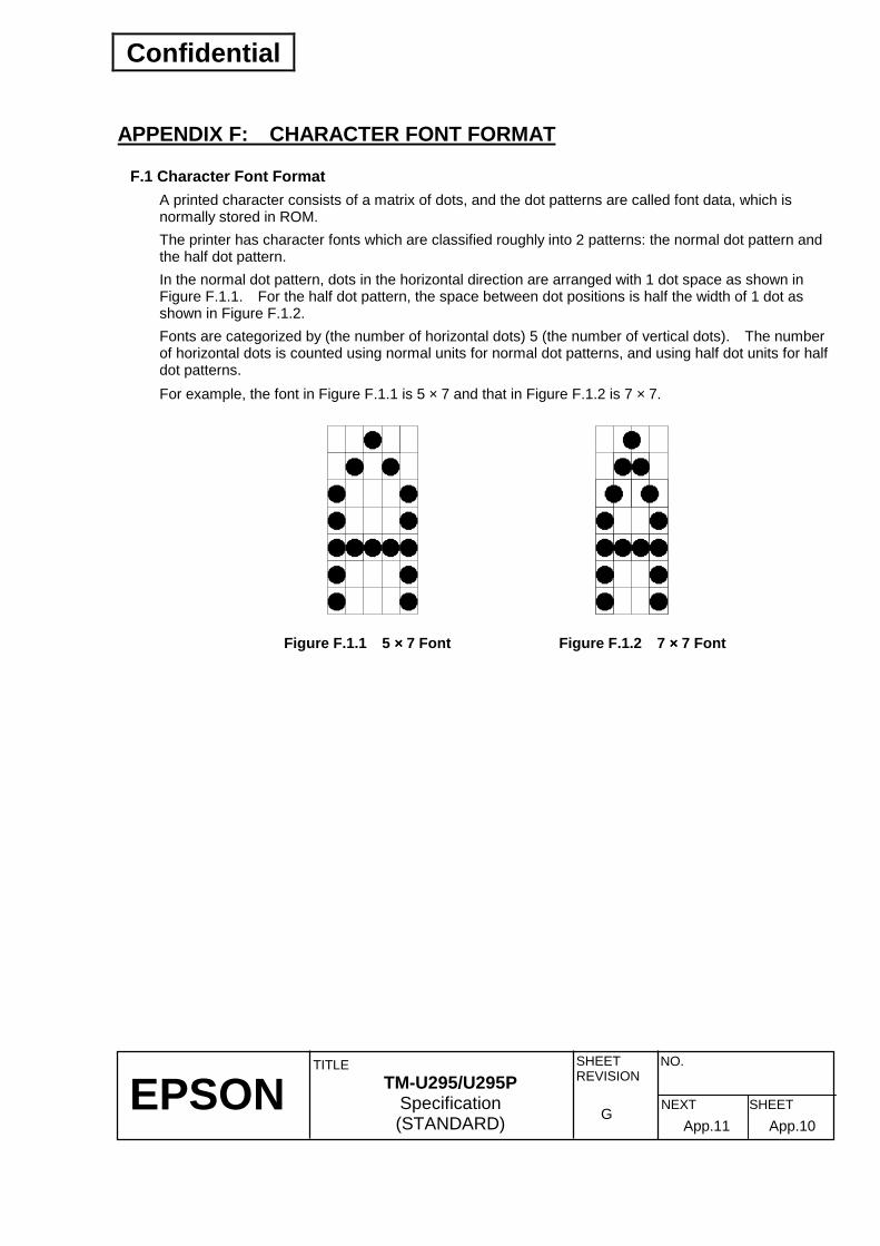
Confidential
EPSON
TITLE SHEET REVISION
NO.
SHEETNEXT G
TM-U295/U295P Specification (STANDARD) App.10App.11
APPENDIX F: CHARACTER FONT FORMAT
F.1 Character Font Format A printed character consists of a matrix of dots, and the dot patterns are called font data, which is normally stored in ROM. The printer has character fonts which are classified roughly into 2 patterns: the normal dot pattern and the half dot pattern. In the normal dot pattern, dots in the horizontal direction are arranged with 1 dot space as shown in Figure F.1.1. For the half dot pattern, the space between dot positions is half the width of 1 dot as shown in Figure F.1.2. Fonts are categorized by (the number of horizontal dots) 5 (the number of vertical dots). The number of horizontal dots is counted using normal units for normal dot patterns, and using half dot units for half dot patterns. For example, the font in Figure F.1.1 is 5 × 7 and that in Figure F.1.2 is 7 × 7.
Figure F.1.2 7 ×××× 7 Font Figure F.1.1 5 ×××× 7 Font

Confidential
EPSON
TITLE SHEET REVISION
NO.
SHEETNEXT G
TM-U295/U295P Specification (STANDARD) App.11App.12
The actual character width is defined by print density in the horizontal direction and the number of horizontal dots per character. Standard character width consists of this character width plus right-side spacing of the character. Standard character width is used as a reference for setting the number of printable characters per line. The character width for an actual printed character is called print character width. Print character width may be larger than standard character width, depending on the settings of the right side spacing and the double-width mode.
Standard character width
Space
Actual characterwidth
Figure F.1.3 Character Structure
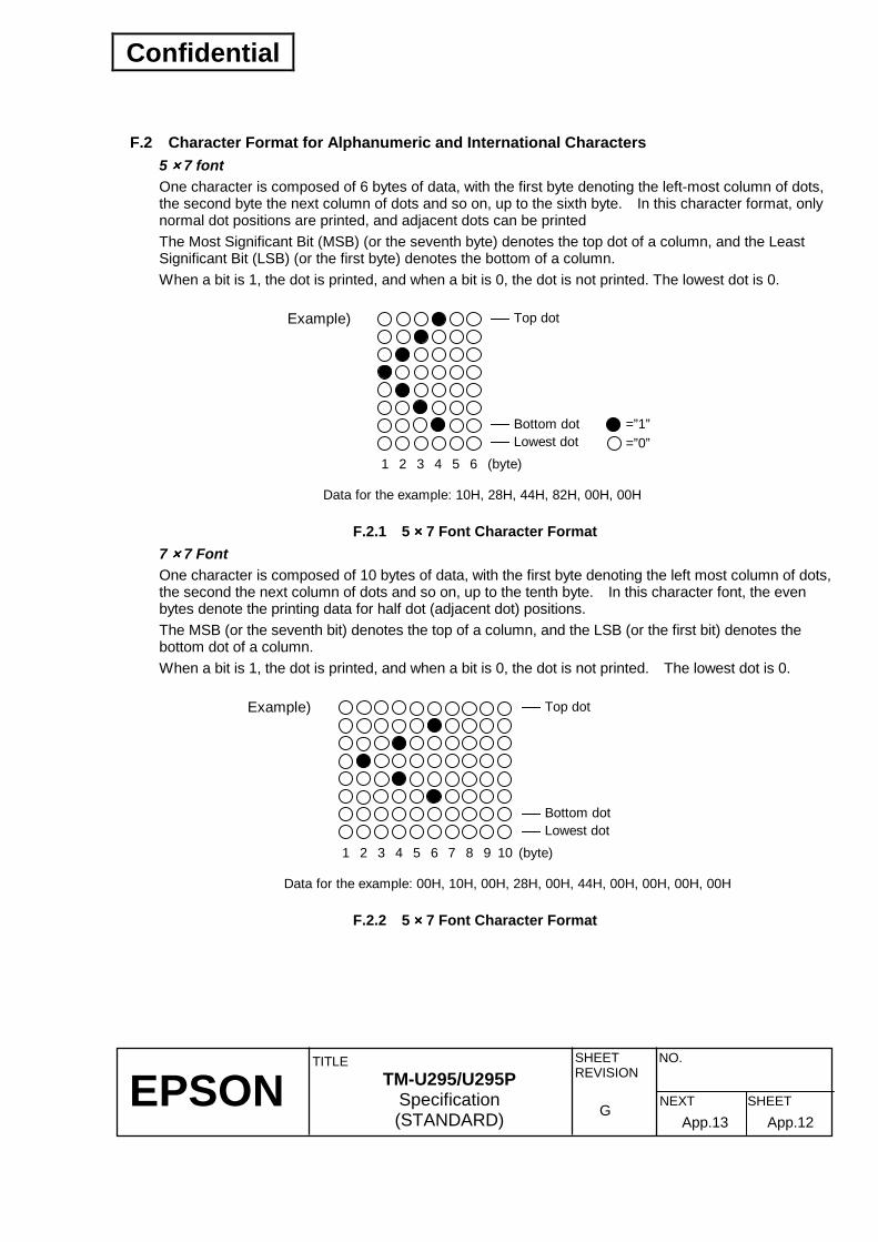
Confidential
EPSON
TITLE SHEET REVISION
NO.
SHEETNEXT G
TM-U295/U295P Specification (STANDARD) App.12App.13
F.2 Character Format for Alphanumeric and International Characters 5 ×××× 7 font One character is composed of 6 bytes of data, with the first byte denoting the left-most column of dots, the second byte the next column of dots and so on, up to the sixth byte. In this character format, only normal dot positions are printed, and adjacent dots can be printed The Most Significant Bit (MSB) (or the seventh byte) denotes the top dot of a column, and the Least Significant Bit (LSB) (or the first byte) denotes the bottom of a column. When a bit is 1, the dot is printed, and when a bit is 0, the dot is not printed. The lowest dot is 0.
Example) Top dot
(byte)654321
Bottom dot
Data for the example: 10H, 28H, 44H, 82H, 00H, 00H
Lowest dot=”1”=”0”
F.2.1 5 ×××× 7 Font Character Format 7 ×××× 7 Font One character is composed of 10 bytes of data, with the first byte denoting the left most column of dots, the second the next column of dots and so on, up to the tenth byte. In this character font, the even bytes denote the printing data for half dot (adjacent dot) positions. The MSB (or the seventh bit) denotes the top of a column, and the LSB (or the first bit) denotes the bottom dot of a column. When a bit is 1, the dot is printed, and when a bit is 0, the dot is not printed. The lowest dot is 0.
Example)
(byte)654321
Data for the example: 00H, 10H, 00H, 28H, 00H, 44H, 00H, 00H, 00H, 00H
Top dot
Bottom dotLowest dot
10987
F.2.2 5 ×××× 7 Font Character Format

Confidential
EPSON
TITLE SHEET REVISION
NO.
SHEETNEXT G
TM-U295/U295P Specification (STANDARD) App.13App.14
F.3 Format for Graphic Characters 5 ×××× 7 font One character is composed of 6 bytes of data, with the first byte denoting the left-most column of dots, the second byte the next column of dots and so on, up to the sixth byte. In this character format, only normal dot positions are printed, and adjacent dots can be printed. The MSB (or the seventh bit) denotes the top dot of a column, and the LSB (or the first bit) denotes the bottom dot of a column. When a bit is 1, the dot is printed, and when a bit is 0, the dot is not printed. The lowest dot is 0.
Example) Top dot
(byte)654321
Bottom dot
Data for the example: FEH, FEH, FEH, FEH, FEH, FEH
Lowest dot=”1”=”0”
Figure F.3.1 5 ×××× 7 Font Character Format 7 ×××× 7 font One character is composed of 10 bytes of data, with the first byte denoting the left-most column of dots, the second byte the next column of dots and so on, up to the tenth byte. In this character format, the even bytes denote the printing data for half dot (adjacent dot) positions. The MSB (or the seventh bit) denotes the top dot of a column, and the LSB (or the first bit) denotes the bottom dot of a column. When a bit is 1, the dot is printed, and when a bit is 0, the dot is not printed. The lowest dot is 0.
Example)
(byte)654321
Data for the example: FEH, 00H, FEH, 00H, FEH, 00H, FEH, 00H, FEH, 00H
Top dot
Bottom dotLowest dot
10987
Figure F.3.2 7 ×××× 7 Font Character Format

Confidential
EPSON
TITLE SHEET REVISION
NO.
SHEETNEXT G
TM-U295/U295P Specification (STANDARD) App.14App.15
APPENDIX G: COMPARISON TABLE FOR TM-290IIIIIIII AND TM-U295 The TM-290II and the TM-U295 differ in the following points: 1) DIP switches
DIP Switch TM-290II TM-U295 SW1-1 Data receive error Data receive error SW1-2 Data buffer capacity Data buffer capacity SW1-3 Handshaking Handshaking SW1-4 Data word length Data word length SW1-5 Parity Parity SW1-6 Parity selection Parity selection SW1-7 SW1-8
Transmission speed selection 1200, 2400, 4800, 9600 bps
SW1-9
Transmission speed selection 110,150, 300, 600, 1200, 2400, 4800, 9600 bps Pin 6 Reset signal
SW1-10 Not used Pin 6 Reset signal 2) Buttons
Button TM-290II TM-U295 Power button Not equipped Equipped Reset button Equipped Not equipped
3) Drawer kick-out connector signal
Pin Number TM-290II TM-U295 1 Frame GND Frame GND 2 Drawer kick-out drive signal Drawer kick-out drive signal 3 Drawer open/close signal Drawer open/close signal 4 +24 V +24 V 5 N.C Drawer kick-out drive signal 2 6 Signal GND Signal GND

Confidential
EPSON
TITLE SHEET REVISION
NO.
SHEETNEXT G
TM-U295/U295P Specification (STANDARD) App.15App.16
4) Interface signal (D-SUB25)
Pin Number TM-290II TM-U295 1 FG FG 2 TXD TXD 3 RXD RXD 4 -- RTS (same as DTR) 6 DSR DSR 7 SG SG 20 DTR DTR 25 -- INIT
5) Added Commands
Command TM-290II TM-U295 DLE EOT -- Real-time status transmission ESC = -- Select peripheral device GS I -- Transmit printer ID
GS a -- Enable/disable Automatic Status Back (ASB)
GS r -- Transmit status 6) Commands to which the ranges are added
Command TM-290II TM-U295 ESC T 0 ≤ n ≤ 3 0 ≤ n ≤ 3, 48 ≤ n ≤ 51 ESC p n = 3 0 ≤ n ≤ 1, 48 ≤ n ≤ 49 ESC t 0 ≤ n ≤ 1 0 ≤ n ≤ 2 ESC u n = 0 n = 0, 48
7) Character code
TM-290II TM-U295 Character code table ESC t
Page 0, 1 0 ≤ n ≤ 1
Page 0, 1, 2 0 ≤ n ≤ 2

Confidential
EPSON
TITLE SHEET REVISION
NO.
SHEETNEXT G
TM-U295/U295P Specification (STANDARD) App.16App.17
8) Command specification differences
Command TM-290II TM-U295 ESC T, ESC W Disabled in standard mode. Has no effect in standard mode. ESC , ESC ! 7×7 font, ESC ! underline
Disabled in Page mode. Has no effect in page mode.
ESC W Spreads print area to 8 dot when print area is below 8 dot (both of x and y).
Does not spread print area to 8 dot when print area is below 8 dot. When print area is 0, this command is ignored.
HT
When this command is executed at the end of a line in standard mode, a tab is executed at the beginning of the next line. In page mode, only line feed is executed.
When this command is executed at the end of line, a tab is executed at the beginning of the next line in both of standard and page modes.
9) Self-test operation
TM-290II TM-U295 Current printer status printing and self test printing
Continuous. After printing the current printer status, the printer ejects the paper and executes self test printing on the next paper.
Paper-out printing stop
Disabled. Enabled.
END