slip yoke eliminator kit for np231 part number 11400 yoke eliminator kit for np231 part number 11400...
TRANSCRIPT
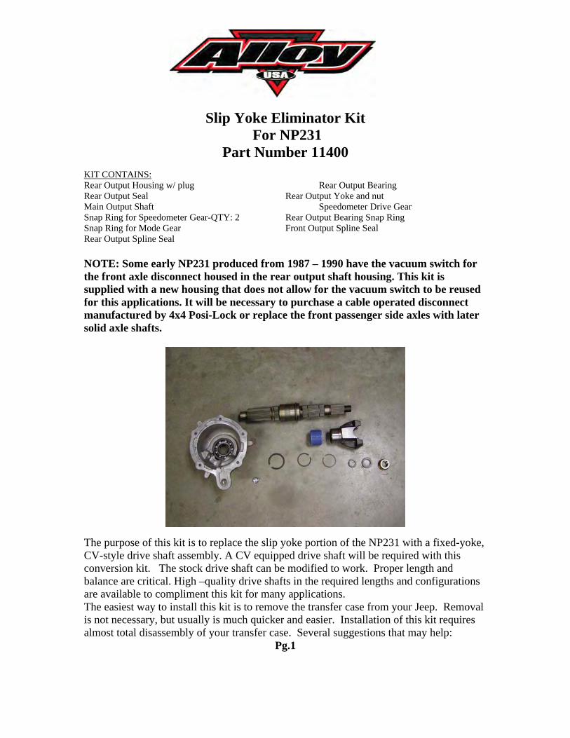
Slip Yoke Eliminator Kit For NP231
Part Number 11400KIT CONTAINS:Rear Output Housing w/ plug Rear Output BearingRear Output Seal Rear Output Yoke and nutMain Output Shaft Speedometer Drive GearSnap Ring for Speedometer Gear-QTY: 2 Rear Output Bearing Snap RingSnap Ring for Mode Gear Front Output Spline SealRear Output Spline Seal
NOTE: Some early NP231 produced from 1987 – 1990 have the vacuum switch for the front axle disconnect housed in the rear output shaft housing. This kit is supplied with a new housing that does not allow for the vacuum switch to be reusedfor this applications. It will be necessary to purchase a cable operated disconnect manufactured by 4x4 Posi-Lock or replace the front passenger side axles with later solid axle shafts.
The purpose of this kit is to replace the slip yoke portion of the NP231 with a fixed-yoke,CV-style drive shaft assembly. A CV equipped drive shaft will be required with this conversion kit. The stock drive shaft can be modified to work. Proper length and balance are critical. High –quality drive shafts in the required lengths and configurations are available to compliment this kit for many applications.The easiest way to install this kit is to remove the transfer case from your Jeep. Removal is not necessary, but usually is much quicker and easier. Installation of this kit requiresalmost total disassembly of your transfer case. Several suggestions that may help:
Pg.1
(1) The installation of this kit requires you to nearly disassemble the entire case. If you need to rebuild, or feel like you have additional worn parts, now would be the time to do so.
(2) Obtain a service manual for your Jeep. This will provide illustrations and information regarding parts identification, torque values, and other important data.
(3) Use photos, and notes; mark and label all parts for future reference. (4) Keep all bolts, nuts, washers, ect. separated into groups as you remove them.
Place inside zip-lock bags and mark location removed from. (5) Make sure you have all the required tools, pre-lubricants, RTV sealant (OEM part
number : 82300234), thread-locker, and a clean work area. (6) Make sure you have the time needed to perform this conversion without being
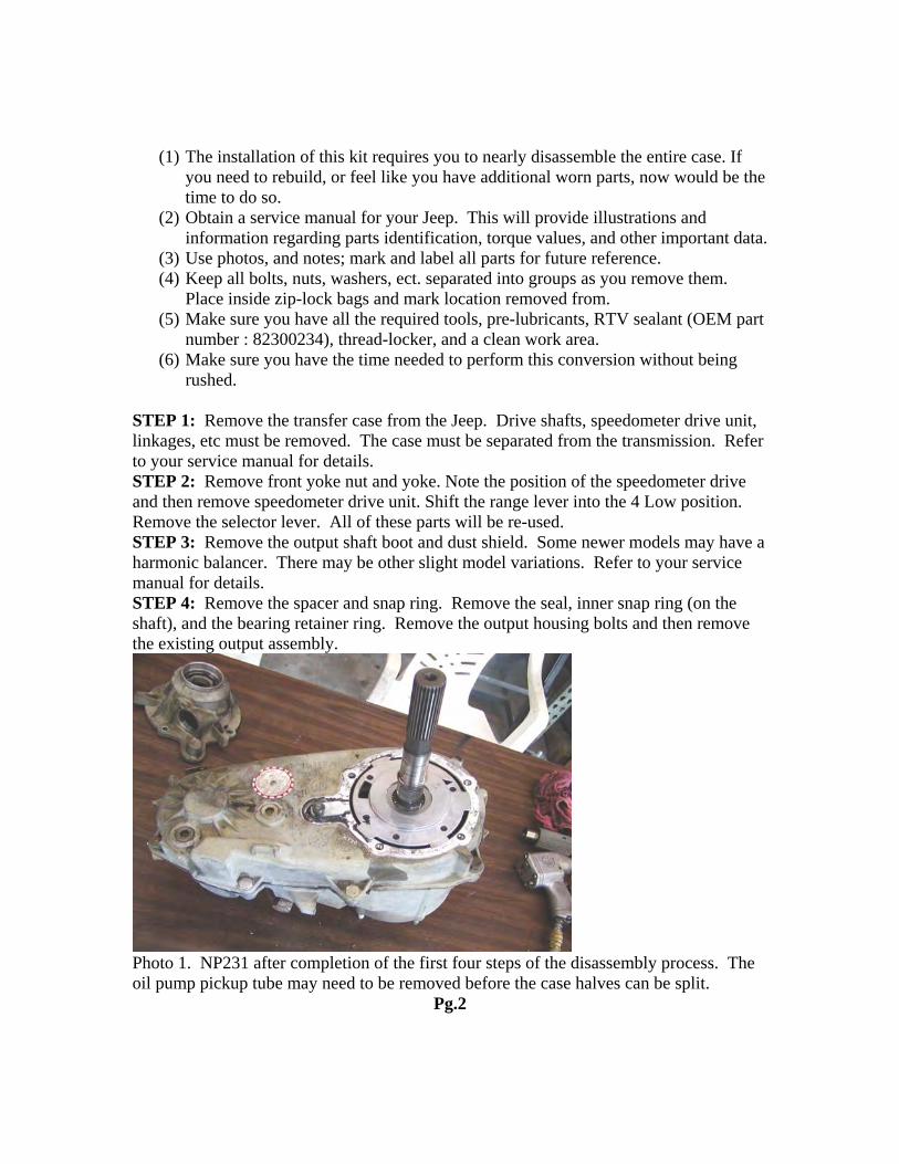
rushed. STEP 1: Remove the transfer case from the Jeep. Drive shafts, speedometer drive unit, linkages, etc must be removed. The case must be separated from the transmission. Refer to your service manual for details. STEP 2: Remove front yoke nut and yoke. Note the position of the speedometer drive and then remove speedometer drive unit. Shift the range lever into the 4 Low position. Remove the selector lever. All of these parts will be re-used. STEP 3: Remove the output shaft boot and dust shield. Some newer models may have a harmonic balancer. There may be other slight model variations. Refer to your service manual for details. STEP 4: Remove the spacer and snap ring. Remove the seal, inner snap ring (on the shaft), and the bearing retainer ring. Remove the output housing bolts and then remove the existing output assembly.
Photo 1. NP231 after completion of the first four steps of the disassembly process. The oil pump pickup tube may need to be removed before the case halves can be split.
Pg.2
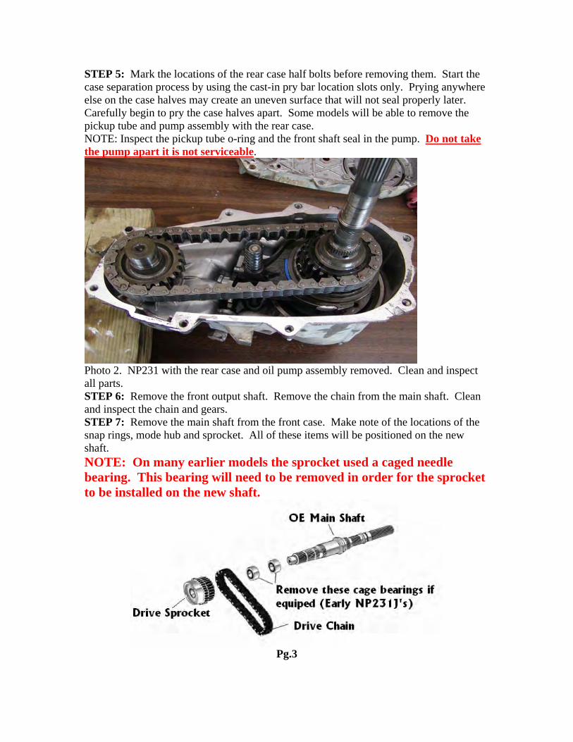
STEP 5: Mark the locations of the rear case half bolts before removing them. Start the case separation process by using the cast-in pry bar location slots only. Prying anywhere else on the case halves may create an uneven surface that will not seal properly later. Carefully begin to pry the case halves apart. Some models will be able to remove the pickup tube and pump assembly with the rear case. NOTE: Inspect the pickup tube o-ring and the front shaft seal in the pump. Do not take the pump apart it is not serviceable.
Photo 2. NP231 with the rear case and oil pump assembly removed. Clean and inspect all parts. STEP 6: Remove the front output shaft. Remove the chain from the main shaft. Clean and inspect the chain and gears. STEP 7: Remove the main shaft from the front case. Make note of the locations of the snap rings, mode hub and sprocket. All of these items will be positioned on the new shaft. NOTE: On many earlier models the sprocket used a caged needle bearing. This bearing will need to be removed in order for the sprocket to be installed on the new shaft.
Pg.3
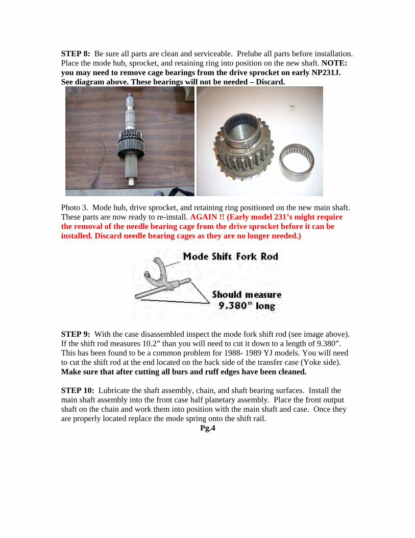
STEP 8: Be sure all parts are clean and serviceable. Prelube all parts before installation. Place the mode hub, sprocket, and retaining ring into position on the new shaft. NOTE: you may need to remove cage bearings from the drive sprocket on early NP231J. See diagram above. These bearings will not be needed – Discard.
Photo 3. Mode hub, drive sprocket, and retaining ring positioned on the new main shaft. These parts are now ready to re-install. AGAIN !! (Early model 231’s might require the removal of the needle bearing cage from the drive sprocket before it can be installed. Discard needle bearing cages as they are no longer needed.)
STEP 9: With the case disassembled inspect the mode fork shift rod (see image above). If the shift rod measures 10.2” than you will need to cut it down to a length of 9.380”. This has been found to be a common problem for 1988- 1989 YJ models. You will need to cut the shift rod at the end located on the back side of the transfer case (Yoke side). Make sure that after cutting all burs and ruff edges have been cleaned. STEP 10: Lubricate the shaft assembly, chain, and shaft bearing surfaces. Install the main shaft assembly into the front case half planetary assembly. Place the front output shaft on the chain and work them into position with the main shaft and case. Once they are properly located replace the mode spring onto the shift rail.
Pg.4
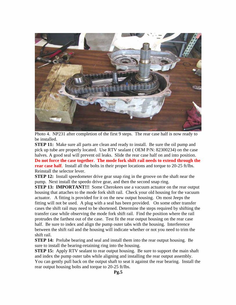
Photo 4. NP231 after completion of the first 9 steps. The rear case half is now ready to be installed. STEP 11: Make sure all parts are clean and ready to install. Be sure the oil pump and pick up tube are properly located. Use RTV sealant ( OEM P/N: 82300234) on the case halves. A good seal will prevent oil leaks. Slide the rear case half on and into position. Do not force the case together. The mode fork shift rail needs to extend through the rear case half. Install all the bolts in their proper locations and torque to 20-25 ft/lbs. Reinstall the selector lever. STEP 12: Install speedometer drive gear snap ring in the groove on the shaft near the pump. Next install the speedo drive gear, and then the second snap ring. STEP 13: IMPORTANT!!! Some Cherokees use a vacuum actuator on the rear output housing that attaches to the mode fork shift rail. Check your old housing for the vacuum actuator. A fitting is provided for it on the new output housing. On most Jeeps the fitting will not be used. A plug with a seal has been provided. On some other transfer cases the shift rail may need to be shortened. Determine the steps required by shifting the transfer case while observing the mode fork shift rail. Find the position where the rail protrudes the farthest out of the case. Test fit the rear output housing on the rear case half. Be sure to index and align the pump outer tabs with the housing. Interference between the shift rail and the housing will indicate whether or not you need to trim the shift rail. STEP 14: Prelube bearing and seal and install them into the rear output housing. Be sure to install the bearing-retaining ring into the housing. STEP 15: Apply RTV sealant to rear output housing. Be sure to support the main shaft and index the pump outer tabs while aligning and installing the rear output assembly. You can gently pull back on the output shaft to seat it against the rear bearing. Install the rear output housing bolts and torque to 20-25 ft/lbs.
Pg.5
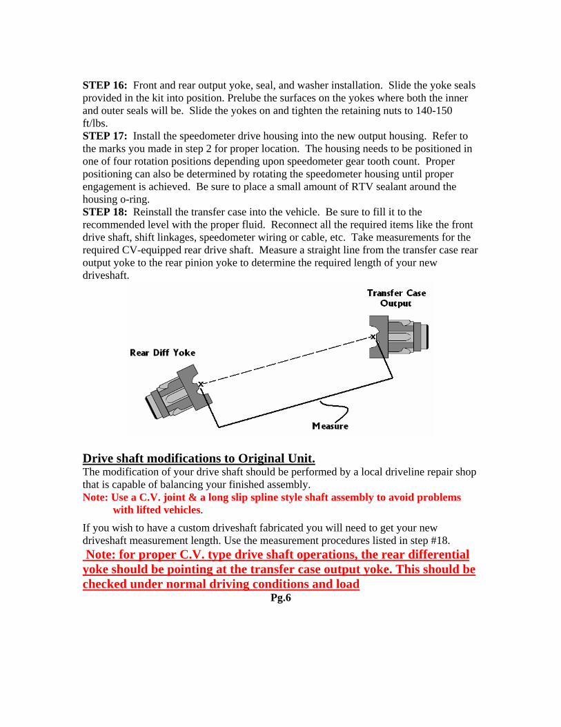
STEP 16: Front and rear output yoke, seal, and washer installation. Slide the yoke seals provided in the kit into position. Prelube the surfaces on the yokes where both the inner and outer seals will be. Slide the yokes on and tighten the retaining nuts to 140-150 ft/lbs. STEP 17: Install the speedometer drive housing into the new output housing. Refer to the marks you made in step 2 for proper location. The housing needs to be positioned in one of four rotation positions depending upon speedometer gear tooth count. Proper positioning can also be determined by rotating the speedometer housing until proper engagement is achieved. Be sure to place a small amount of RTV sealant around the housing o-ring. STEP 18: Reinstall the transfer case into the vehicle. Be sure to fill it to the recommended level with the proper fluid. Reconnect all the required items like the front drive shaft, shift linkages, speedometer wiring or cable, etc. Take measurements for the required CV-equipped rear drive shaft. Measure a straight line from the transfer case rear output yoke to the rear pinion yoke to determine the required length of your new driveshaft.
Drive shaft modifications to Original Unit. The modification of your drive shaft should be performed by a local driveline repair shop that is capable of balancing your finished assembly. Note: Use a C.V. joint & a long slip spline style shaft assembly to avoid problems with lifted vehicles.
If you wish to have a custom driveshaft fabricated you will need to get your new driveshaft measurement length. Use the measurement procedures listed in step #18. Note: for proper C.V. type drive shaft operations, the rear differential yoke should be pointing at the transfer case output yoke. This should be checked under normal driving conditions and load
Pg.6
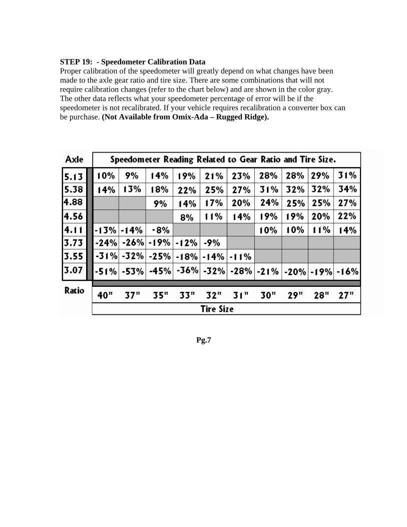
STEP 19: - Speedometer Calibration Data Proper calibration of the speedometer will greatly depend on what changes have beenmade to the axle gear ratio and tire size. There are some combinations that will not require calibration changes (refer to the chart below) and are shown in the color gray.The other data reflects what your speedometer percentage of error will be if the speedometer is not recalibrated. If your vehicle requires recalibration a converter box can be purchase. (Not Available from Omix-Ada – Rugged Ridge).
Pg.7
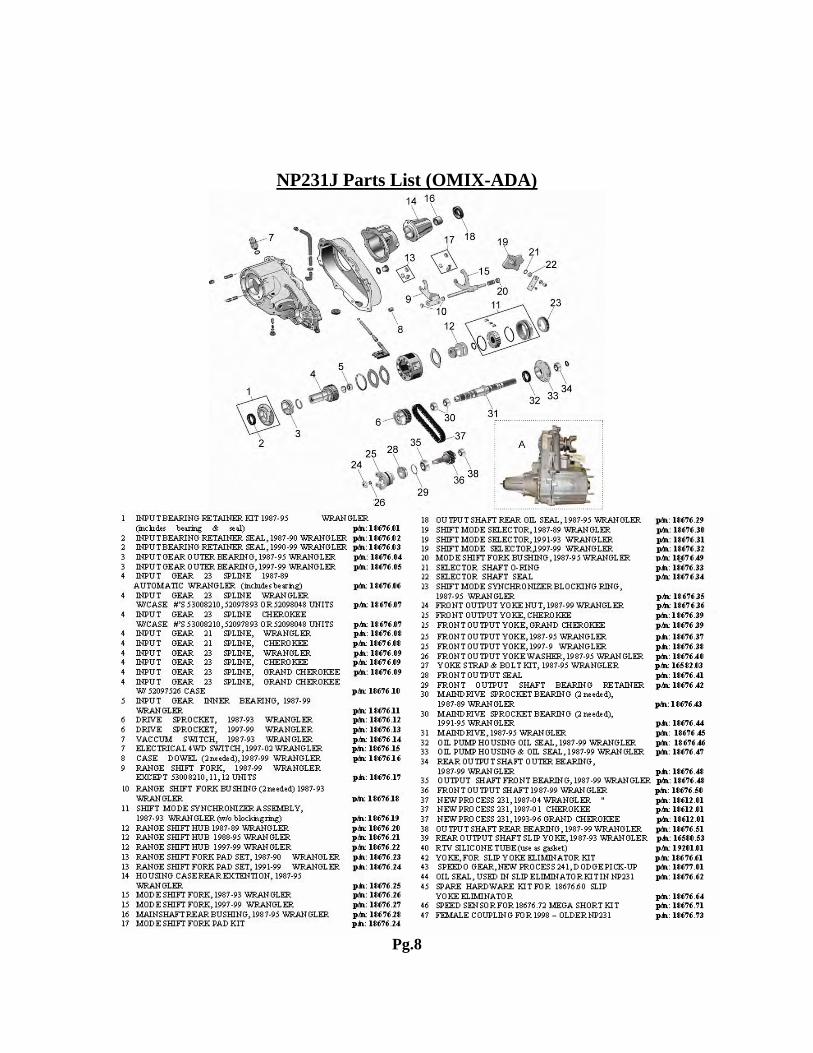
NP231J Parts List (OMIX-ADA)
Pg.8