slope stability analysis performed for concept c proposed ... · geotechnical engineers october 26,...
TRANSCRIPT

ASSOCIATES,INC
Geotechnical Engineers October 26, 2010
New Ventures Associates, LLC85-87 Boston StreetEverett, MA 02149
Attention: Messrs. Willam Thibeault and Steven Trettel
Reference: Crow Lane Landfill Corrective Action Design; Newburyport, MassachusettsSlope Stability Analysis Performed for Concept C Proposed Berm
Messrs. Wiliam Thibeault and Steven Trettel:
This letter documents the results of our slope stabilty analysis for the proposed Concept C site gradingassociated with the corrective action design for the Crow Lane Landfill located in Newburyport,Massachusetts. Furthermore, this letter responds to comments on the slope stability analysis by theMassachusetts Department of Environmental Protection (DEP) in e-mails originating from John Carrigandated October 5 and 19, 2010.
Stabiltv Analvsis Results
The current proposed corrective action design (Concept C) includes the construction of a 2 horizontal (h)to 1 vertical (v) berm over the existing berm. A slope stability analysis was performed to determine thefactor of safety against slope failure for both the existing and proposed Concept C conditions. The keycomponent of the stability of the existing and proposed berm is the undrained shear strength, Su, of a 24 to55-foot thick deposit of marine clay that underlies the site. The upper bound shear strength profileconsidered by McPhail Associates, Inc. to be representative of the actual conditions and utilized in ouranalysis is discussed in further detail under the section of this letter entitled "Soil Properties for SlopeStability Analysis."
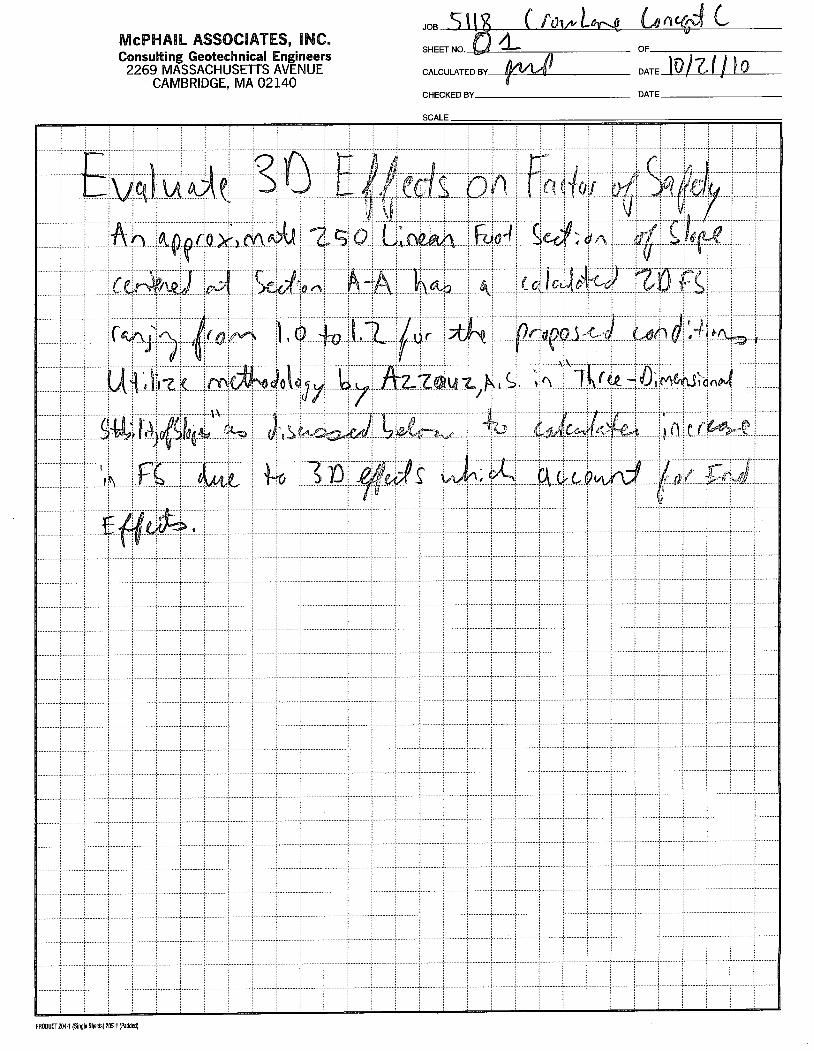
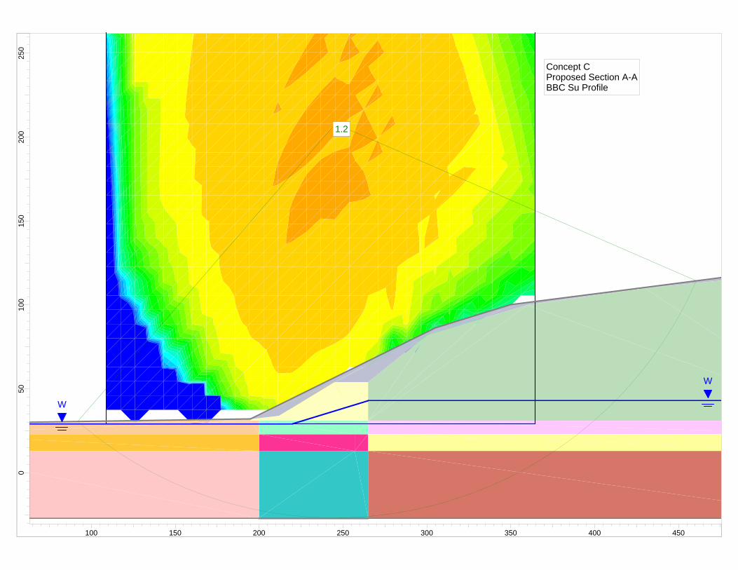
Our analysis focused on a critical cross-section of the berm, Section A-A, where the proposed grading isthe highest and the clay deposit is the thickest. The location of Section A-A is indicated on the attachedFigure 1. The two-dimensional factor of safety for our slope stability analysis of Section A-A utilizing thecomputer program SLIDE developed by Rocscience, Inc. was computed to be 1.2. However, since thecritical section analyzed is of limited length, the two-dimensional factor of safety can be increased toaccount for three-dimensional effects.
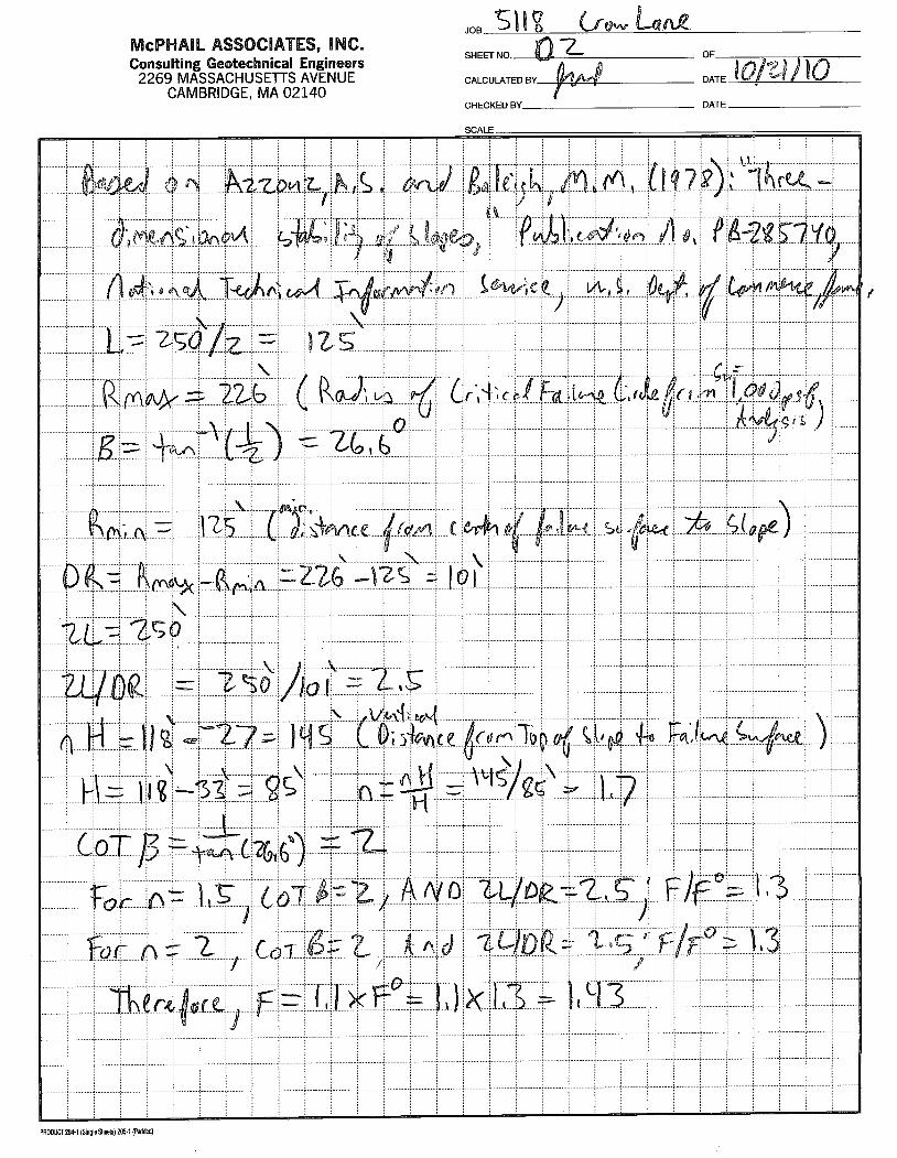
Three dimensional effects, which take into consideration end effects, typically increase the factor of safetyagainst slope failure computed using two.,dimensional methods. Methodology presented by A.S. Azzouzin a 1978 publication entitled "Three-Dimensional Stability of Slopes" was utilized by McPhail to calculatethe three-dimensional factor of safety for Section A-A. Using Azzouz's methodology, the two-dimensionalfactor of safety can be increased by approximately 30-percent to account for three-dimensional effects ofthe berm geometry.
Therefore, utiizing the computed two-dimensional factor of safety of 1.2 for Section A-A and an increaseof 30 percent to account for three-dimensional effects, the resulting three-dimensional factor of safety isestimated to be about 1.6. A summary of our slope stability analysis results is presented in Table 1. Thederivation of the three-dimensional factor of safety for Section A-A is included in Appendix A.
2269 Massachusetts Avenue
Cambridge, Massachusetts 02140
617/868.1420617 1868.1423 (Fax)
Geotechnical Engineers
New Ventures Associates, LLCOctober 26, 2010Page 2
ASSOCIATES,INC
It should also be noted that the Section A-A factor of safety against slope failure for the proposed gradingconditions remains essentially unchanged as compared to the factor of safety computed for the existingconditions. As presented herein for other sections analyzed with different shear strength profiles, a similarconclusion was reached. Therefore, based upon the results of our slope stability analysis as containedherein, construction of the 2 h to 1 v berm wil not significantly change the factor of safety againstslope failure from the existing conditions regardless of the shear strength profile utilzed.
Soil Properties for Slope Stabilty Analysis
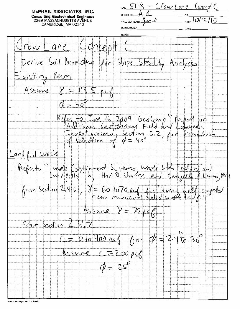
The subsurface conditions present at the site are described in detail in documents prepared previously byGeocomp Corporation of Boxborough, Massachusetts. The derivation of the soil parameters used in thestability analysis by McPhail Associates, Inc. is included in Appendix B. Additional information utilized byMcPhail Associates, Inc. included published research on geotechnical testing performed on a deposit ofmarine clay located in the Newbury/Newburyport area, referred to as Newbury Boston Blue Clay (NBBC).These references include:
A doctor of philosophy dissertation submitted to the Graduate School of the University ofMassachusetts Amherst entitled "Evaluation of Soil Suction as an Indicator of Sample Quality for aSoft Saturated Marine Clay" prepared by Steven E. Poirier, dated May 2005; and
A study entitled "An Instrumented Multiple Deployment Model Pile (MDMP)" by the FederalHighway Administration (FHWA)" http://ww.tfrc.gov/structur/pubs/99194/05.htm.
It is noted that the Poirier and FHWA papers each contain research performed on the NBBC from thesame Route 1 bridge site in Newbury, Massachusetts. In consideration that the Poirier paper containssignificantly more data obtained from geotechnical testing of the NBBC than the FHWA paper, datapresented in Poirier's paper were utilized in our analysis to model the possible lower bound shear strengthof the marine clay.
The key component of the slope stability analysis is the undrained shear strength, Su, of a 24 to 55-footthick deposit of marine clay that underlies the site. The Stress History and Normalized Soil EngineeringProperties (SHANSEP) method was used to estimate a lower bound and upper bound undrained shearstrength, su' of the marine clay deposit. The SHANSEP method allows the undrained shear strength to becalculated utilizing the stress history of the deposit in conjunction with the equation, Su!cr'v = S X OCRM,
where: cr'v = in-situ effective vertical stress, cr'vm = maximum past pressure, OCR = over-consolidation ratio(cr'vm/cr'v), and Sand M are the SHANSEP parameters.
The SHANSEP parameters, Sand M, from the above referenced publication by Poirier on the NBBC andfrom widely published data by Professor C.C. Ladd on a deposit of marine clay in the Boston area,referred to as Boston Blue Clay (BBC), were utilized. The SHANSEP parameters determined by Poirierand Ladd are considered to represent the possible range of lower and upper bound strengths,respectively, of the marine clay deposit at the project site.

ASSOCIATES,INC New Ventures Associates, LLCOctober 26, 2010Page 3Geotechnical Engineers
The following are the equations which were used to calculate the lower and upper bound shear strengthprofile:
Lower Bound Su: SJcr'v = 0.19 x OCRo.62 (From Poirier work on NBBC)
Upper Bound Su: SJcr'v = 0.2 x OCRo.8 (From Ladd work on BBC)
McPhail Associates, Inc. used the results of four (4) consolidation tests performed on the marine clayconducted by Geocomp to estimate the OCR of the marine clay deposit. The maximum past pressure,cr'vm' of three of the samples was interpreted by McPhail Associates, Inc. from the consolidation test dataprovided. We note that the data obtained from the consolidation test performed on the sample from boringB-2 indicates that the sample has been significantly disturbed such that interpretation of cr'vm could notaccurately be estimated. The attached Table 2 presents a summary of the estimated stress history of themarine clay deposit.
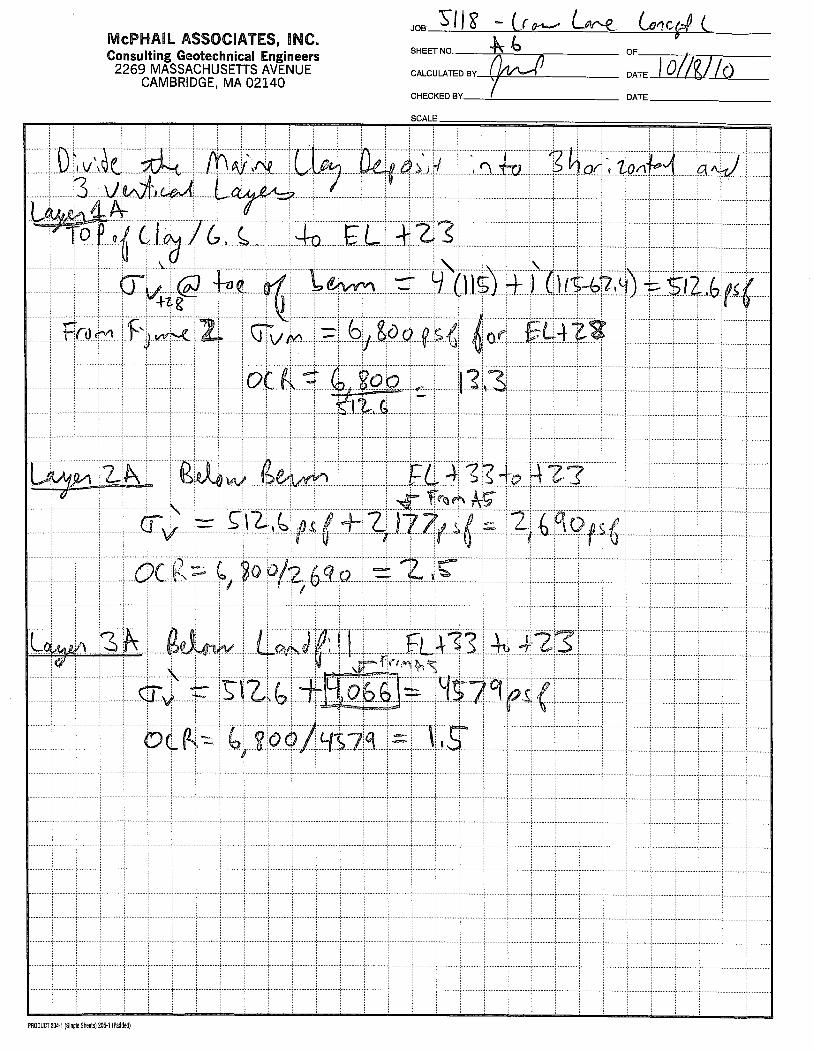
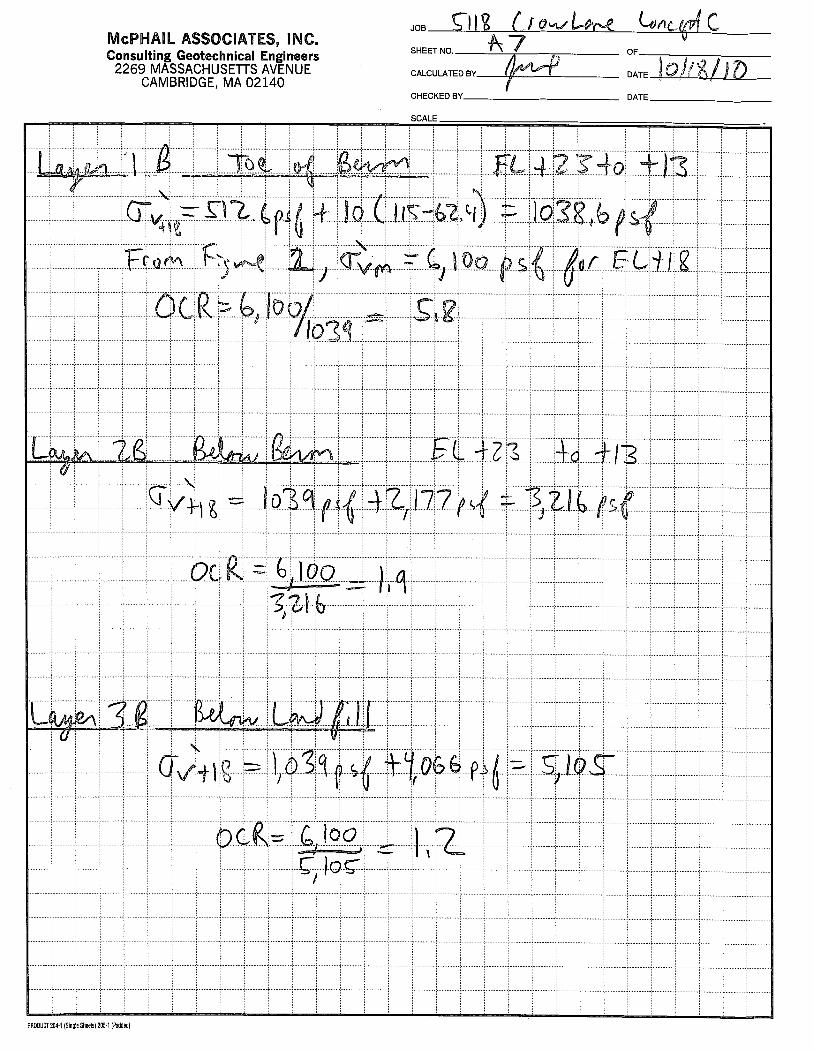
The in-situ vertical effective stress, cr'v' of soil located beneath the berm and landfill is higher than soillocated outside the footprint of the berm and landfiL. For example, the soil beneath the landfill is locatedbeneath approximately 80 feet of soil and refuse. Due to the weight of the additional material overlying themarine clay deposit beneath the berm and landfill, higher undrained shear strengths can be assigned tothe marine clay utilizing the SHANSEP equation at these locations. Calculations of the average increasein the in-situ vertical effective stress beneath the berm and landfill are included in Appendix B. A graphicalsummary of the stress history of the marine clay deposit appears on Figure 2 following the text of thisletter.
The marine clay deposit was divided into a total of nine layers for the purpose of our analysis. Table 3presents a summary of the layers used to characterize the marine clay deposit as utilized in our analysis.The overconsolidation ratio of each of the nine clay layers was determined by obtaining the maximum pastpressure from Figure 2 and dividing it by the calculated in-situ vertical effective stress. Calculations of theOCRs and the in-situ vertical effective stress of each clay layer are included in Appendix B.
Utilizing the OCRs and in-situ vertical effective stress of each of the nine clay layers, the lower and upperbound undrained shear strength of each layer was calculated utilizing the above SHANSEP equationsderived by Poirier and Ladd, respectively. The upper and lower bound undrained shear strength of themarine clay layers located at the toe of the berm, under the berm, and under the landfill utilizing the Poirierand Ladd SHANSEP parameters are presented in the attached Table 3.
The undrained shear strength profile determined using the SHANSEP method for sse correlateswell with the consolidated undrained laboratory triaxial compression tests performed preYiouslyby Geocomp. For that reason we consider the upper bound shear strength profile determined utilizing theSHANSEP BBC equation to be more representative of the shear strength of the marine clay deposit at theproject site.
From a practical standpoint, the marine clay deposit had already undergone its most critical conditionwith regard to slope stability immediately after completion of the existing berm. Upon completion ofexisting berm construction, little consolidation of the marine clay deposit had occurred and the undrainedshear strength of the deposit was at its lowest value. It is understood that no indications of slope instabilitywere observed at that time. Therefore, as the marine clay deposit continues to consolidate with time, the

Geotechnical Engineers
New Ventures Associates, LLCOctober 26, 2010Page 4
marine clay undrained shear strength and the factor of safety with respect to slope stability are increasingwith time as welL.
Groundwater Table Used for Analysis
The groundwater profile utilized in the slope stability analysis was determined based on informationcontained on Geocomp's boring logs. Since water level data was not indicated on the boring logsprovided, the groundwater level in the borings was interpolated based on soil descriptions which indicatedthe soil samples were "wet", "saturated" or "moist".
The groundwater level within borings performed at the toe of the berm was determined to generally varyfrom about Elevation +24.5 to Elevation +33. The groundwater level within borings performed on the bermwas determined to generally vary from Elevation+34 to Elevation +52, excluding areas where moisturedescriptions indicated on the logs was considered to be representative of a locally perched water level in arelatively impervious zone.
For our analysis, the water table was defined at Elevation +29 at the toe of the berm sloping upward toElevation +43 at the interface of the berm and the landfilL. Since our analysis (discussed below) indicatesthat the factor of safety generally remains unchanged from the existing to the proposed conditions, the useof a higher or lower water table is anticipated to affect the existing and proposed conditions similarly, andtherefore, is not considered to be a key factor in the determination of the factor of safety against slopefailure. Since the landfill membrane was installed in the Fall of 2009, runoff into the landfill has beenminimized. Therefore, the groundwater level in the landfill is anticipated to be lower than prior to the Fallof 2009 and should continue to decrease.
Parametric Slope Stabilty Analysis
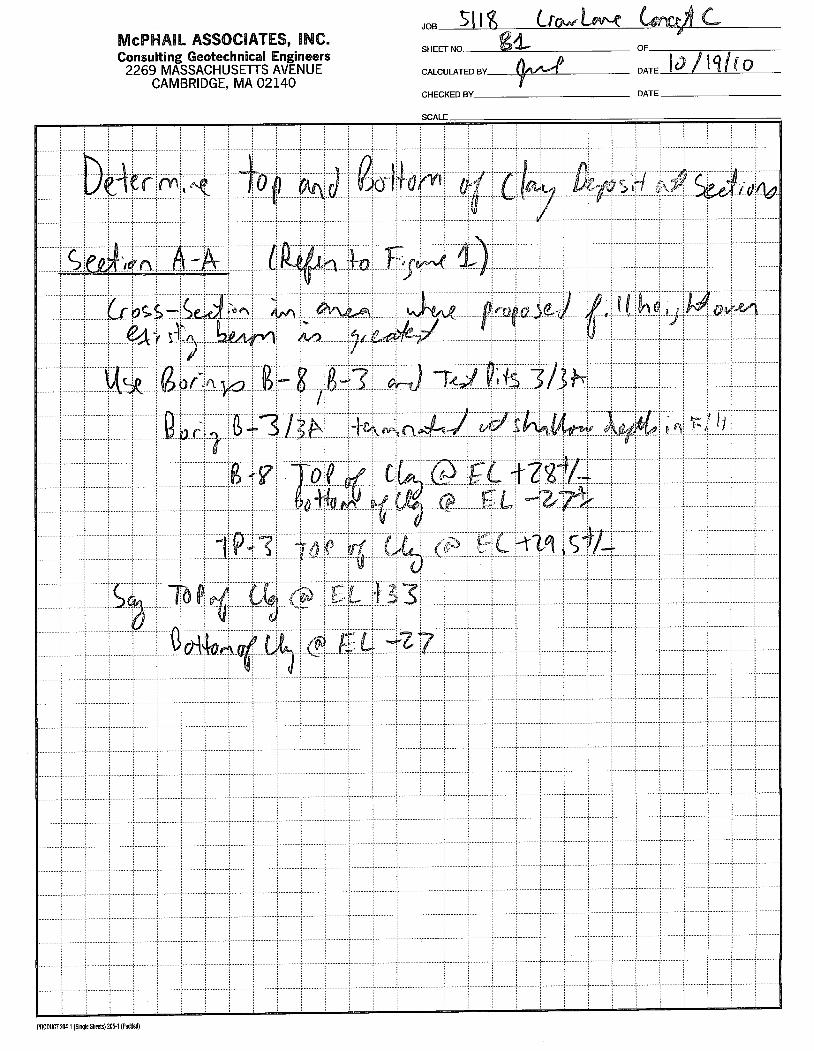
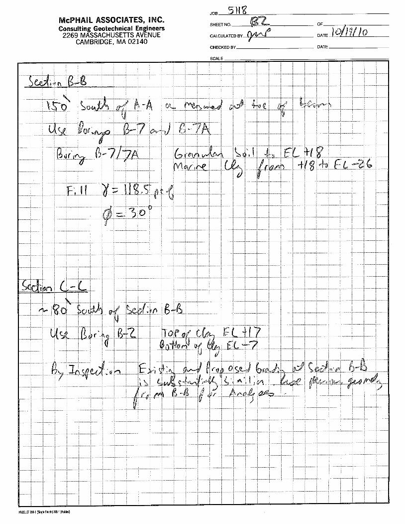
The existing and proposed berm geometry at four (4) sections (A-A, B-B, C-C and D-D) of the westernportion of the berm was adopted from site plans prepared by SITEC, Inc., dated September 30, 2010. Thelocation of the sections analyzed is indicated on the attached Figure 1. The elevation of the top andbottom of the marine clay deposit at each of the four sections was determined based on informationcontained on Geocomp's boring logs, as presented in Appendix C. These cross-sections were selected tomodel variations in the existing and proposed berm geometries and variation in the top and bottomelevation of the marine clay deposit.
The two-dimensional slope stability computer program SLIDE developed by Rocscience, Inc. was utilizedto compute the factor of safety (FS) for existing and proposed conditions using the Bishop Simplified andSpencer Methods. Finally, the two-dimensional slope stability computer program XST ABL was utilized tocompute the FS for the existing and proposed conditions at Section A-A utiizing the Bishop Simplified andBlock Surface - Rankine method.
At the request of Shaw Environmental, Inc., we performed a parametric analysis utiizing a uniformundrained shear strength for the entire marine clay deposit (no vertical or horizontal delineation).Specifically, the existing and proposed conditions at Section A-A were analyzed utilizing uniformundrained shear strengths, Su' of 900, 1,000, and 1,100 pounds per square-foot for the entire marine claydeposit. The computed FS for the various parametric slope stabilty analysis is summarized on the

Geotechnical Engineers
New Ventures Associates, LLCOctober 26, 2010Page 5
ASSOCIATES,INC
attached Table 4. The results of our slope stabilty analysis is attached herein in Appendix D. Theundrained shear strengths assumed for this parametric analysis are not considered to be representative ofthe actual strength of the clay deposit and were conducted primarily at the request of ShawEnvironmental, Inc.
As indicated on the attached Table 4 and as previously identified for the analysis conducted for the criticalSection A-A, the factor of safety against slope failure for the proposed conditions for the various sectionsanalyzed for the different shear strength profiles and the non-critical Sections B-B, C-C and D-D (SeeFigure 1) generally remains unchanged from the factor of safety computed for the existing conditions.Based on our slope stability analysis, construction of the 2 h to 1 y berm wil not change the factor ofsafety against slope failure from the existing conditions regardless of the shear strength profileutilzed.
Influence of DecomposinCl Wood Layer Located Within Berm
A 5 to 11-foot thick deposit consisting of wood fibers mixed with silt, sand and gravel was encounteredwithin the northern side of the northwest portion of the existing berm at a depth of approximately 10 feetbelow the existing top of berm. The construction of the proposed Concept C berm wil raise the grade inthe area of the decomposing wood layer by approximately 10 feet. It is anticipated that some settlementof the decomposing wood layer may result from the additional weight of the proposed berm constructionand as a result of decomposition of the wood layer. Localized ground surface subsidence will likely occuras a result of the settlement, the overall stability of the berm will not be affected because critical failuresurfaces are not located within the berm. Remediation to address deficiencies in the berm as a result ofground subsidence, if required, will consist of placing additional rip-rap in areas where subsidence hasoccurred. Because the previously proposed MSE berm is no longer part of the design, minor subsidenceis not a significant concern.
Preliminary Slope MonitorinCl Plan
The DEP has requested monitoring of the berm performance to permit early detection of potential signs ofslope instability. A series of deformation monitoring points (DMPs) and settlement pl.atforms isrecommended to comply with this request.
Deformation monitoring points would be located about twenty-five (25) feet in front of the toe of the bermwhere feasible, ten (10) feet in front of the berm, and midway between the toe and top of the existingberm. Deformation monitoring points will likely consist of 3/4-inch or 1-inch galvanized steel rods driveninto the ground. The rods will likely be cased with PVC in the upper 3 feet and driven 5 feet below-gradeto locate them below frost depth. Survey prisms will be affxed to the top of each DMP. The northing,easting, and vertical movement of each DMP can be recorded by survey methods to an accuracy of0.01-foot.
Settlement platforms would be installed on the existing berm, midway between the existing berm and thetop of the landfill, and on the top of the existing landfiL. The vertical movement of each settlement platformwill be recorded by survey methods to an accuracy of 0.01-foot.
ASSOCIATES,INC New Ventures Associates, LLCOctober 26, 2010Page 6Geotechnical Engineers
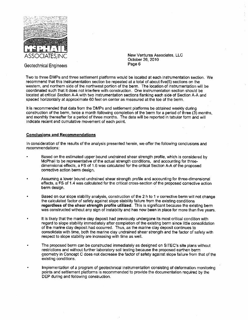
Two to three DMPs and three settlement platforms would be located at each instrumentation section. Werecommend that this instrumentation section be repeated at a total of about five(5) sections on thewestern, and northern side of the northwest portion of the berm. The location of instrumentation will. becoordinated such that it does not interfere with construction. One instrumentation section should belocated at critical Section A-A with two instrumentation sections flanking each side of Section A-A andspaced horizontally at approximate 60 feet on center as measured at the toe of the berm.
It is recommended that data from the DMPs and settlement platforms be obtained weekly duringconstruction of the berm, twice a month following completion of the berm for a period of three (3) months,and monthly thereafter for a period of three months. The data will be reported in tabular form and willindicate recent and cumulative movement of each point.
eonclusions and Recommendations
In consideration of the results of the analysis presented herein, we offer the following conclusions andrecommendations:
Based on the estimated upper bound undrained shear strength profile, which is considered byMcPhail to be representative of the actual strength conditions, and accounting for three-dimensional effects, a FS of 1.6 was calculated for the critical Section A-A of the proposedcorrective action berm design.
Assuming a lower bound undrained shear strength profile and accounting for three-dimensionaleffects, a FS of 1.4 was calculated for the critical cross-section of the proposed corrective actionberm design.
Based on our slope stability analysis, construction of the 2 h to 1 v corrective berm will not changethe calculated factor of safety against slope stability failure from the existing conditionsregardless of the shear strength profile utilzed. This is significant because the existing berm
was constructed without any sign of instability and has now been in place for more than five years.
It is likely that the marine clay deposit had previously undergone its most critical condition withregard to slope stability immediately after completion of the existing berm since little consolidationof the marine clay deposit had occurred. Thus, as the marine clay deposit continues toconsolidate with time, both the marine clay undrained shear strength and the factor of safety withrespect to slope stability are increasing with time as welL.
The proposed berm can be constructed immediately as designed on SITEC's site plans withoutrestrictions and without further laboratory soil testing because the proposed earthen bermgeometry in Concept C does not decrease the factor of safety against slope failure from that of theexisting conditions.
Implementation of a program of geotechnical instrumentation consisting of deformation monitoringpoints and settement platforms is recommended to provide the documentation required by theDEP during and following construction.
ASSOCIATES,INC
Geotechnical Engineers
New Ventures Associates, LLCOctober 26, 2010Page 7
In the event that any changes in nature, design or location of the proposed berm are planned theconclusions and recommendations contained herein should not be considered valid unless the changesare reviewed and conclusions of this letter modified or verified in writing.
We trust that the above is suffcient for your present requirements. Should you have any questionsconcerning the recommendations presented herein, please do not hesitate to call us.
Very truly yours,
McPHAIL ~~c.
Jonathan W. Patch, P.E.
~M.~Chris M. Erikson, P.E.
F:\WP5\JOBS\5118\Concept C\5118_Concept_C_102610_Draft.wpd
JWP/cme
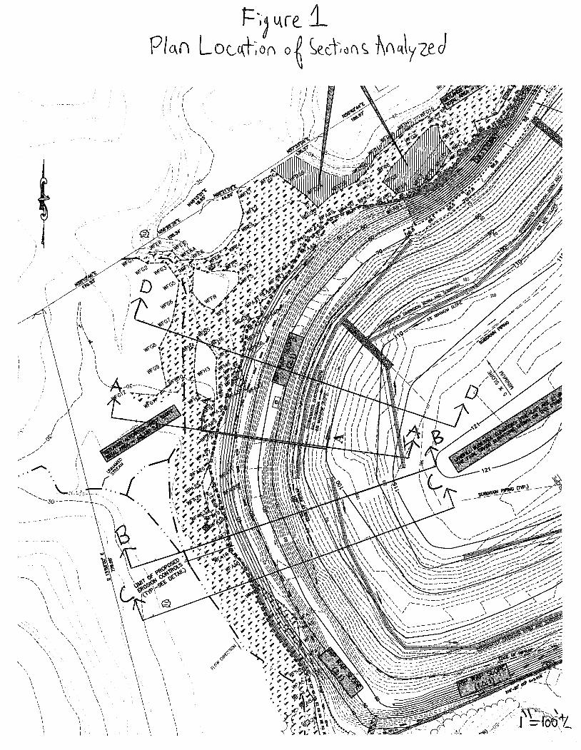

Figure 2Vertical Stress History of Marine Clay
-30
-25
-20
-15
-10
-5
0
5
10
15
20
25
30
35
40
0 1000 2000 3000 4000 5000 6000 7000 8000
Vertical Effective Stress (psf)
Elev
atio
n (F
eet) σ’v Toe Berm
σ’v Under Bermσ’v Under Landfillσ’vm Consolidation Dataσ’vm Max. Past Pressure
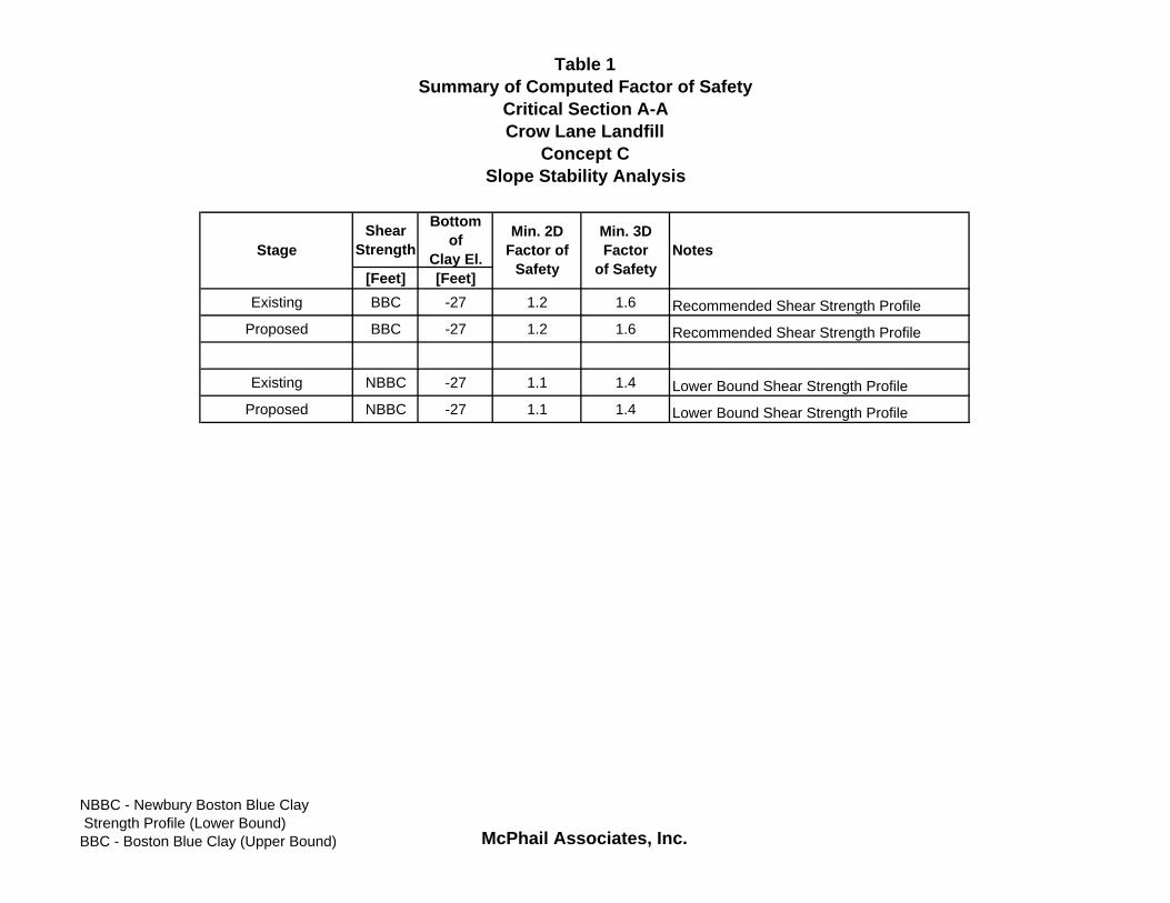
Table 1Summary of Computed Factor of Safety
Critical Section A-ACrow Lane Landfill
Concept CSlope Stability Analysis
Shear Strength
Bottomof
Clay El.[Feet] [Feet]
Existing BBC -27 1.2 1.6 Recommended Shear Strength ProfileProposed BBC -27 1.2 1.6 Recommended Shear Strength Profile
Existing NBBC -27 1.1 1.4 Lower Bound Shear Strength ProfileProposed NBBC -27 1.1 1.4 Lower Bound Shear Strength Profile
Min. 2DFactor of
SafetyNotesStage
Min. 3DFactor
of Safety
NBBC - Newbury Boston Blue Clay Strength Profile (Lower Bound)BBC - Boston Blue Clay (Upper Bound) McPhail Associates, Inc.
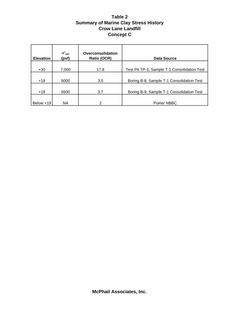
Table 2Summary of Marine Clay Stress History
Crow Lane LandfillConcept C
Elevationσ'vm
(psf)Overconsolidation
Ratio (OCR) Data Source
+30 7,000 17.8 Test Pit TP-3, Sample T-1 Consolidation Test
+19 6000 3.5 Boring B-8, Sample T-1 Consolidation Test
+19 6500 3.7 Boring B-9, Sample T-1 Consolidation Test
Below +19 NA 2 Poirier NBBC
McPhail Associates, Inc.
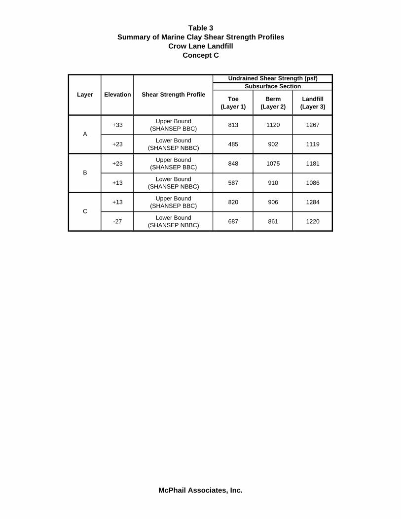
Table 3Summary of Marine Clay Shear Strength Profiles
Crow Lane LandfillConcept C
Toe(Layer 1)
Berm(Layer 2)
Landfill(Layer 3)
+33 Upper Bound(SHANSEP BBC) 813 1120 1267
+23 Lower Bound(SHANSEP NBBC) 485 902 1119
+23 Upper Bound(SHANSEP BBC) 848 1075 1181
+13 Lower Bound(SHANSEP NBBC) 587 910 1086
+13 Upper Bound(SHANSEP BBC) 820 906 1284
-27 Lower Bound(SHANSEP NBBC) 687 861 1220
A
B
C
Undrained Shear Strength (psf)
Layer Elevation Shear Strength ProfileSubsurface Section
McPhail Associates, Inc.

Table 4Summary of Computed Factor of Safety
Non-Critical Sections and Parametric AnalysisCrow Lane Landfill
Concept CSlope Stability Analysis
Shear Strength
Bottomof
Clay El.[Feet] [Feet]
A-A Existing 900 -27 1.0 Uniform Su = 900 psf for Marine Clay DepositA-A Proposed 900 -27 1.0 Uniform Su = 900 psf for Marine Clay Deposit
A-A Existing 1000 -27 1.1 Uniform Su = 1,000 psf for Marine Clay DepositA-A Proposed 1000 -27 1.1 Uniform Su = 1,000 psf for Marine Clay Deposit
A-A Existing 1100 -27 1.2 Uniform Su = 1,100 psf for Marine Clay DepositA-A Proposed 1100 -27 1.2 Uniform Su = 1,100 psf for Marine Clay Deposit
A-A Existing 900 -27 1.2 Block Surface Analysis - Rankine Method: Using XSTABLA-A Proposed 900 -27 1.0 Block Surface Analysis - Rankine Method: Using XSTABL
A-A Existing 900 -27 1.1 Bishop Analysis Using XSTABLA-A Proposed 900 -27 1.2 Bishop Analysis Using XSTABL
B-B Existing NBBC -26 1.2 Lower Bound Shear Strength ProfileB-B Proposed NBBC -26 1.2 Lower Bound Shear Strength Profile
B-B Existing BBC -26 1.3 Upper Bound Shear Strength ProfileB-B Proposed BBC -26 1.3 Upper Bound Shear Strength Profile
C-C Existing NBBC -7 1.4 Lower Bound Shear Strength ProfileC-C Proposed NBBC -7 1.3 Lower Bound Shear Strength Profile
C-C Existing BBC -7 1.4 Upper Bound Shear Strength ProfileC-C Proposed BBC -7 1.4 Upper Bound Shear Strength Profile
D-D Existing NBBC -1 1.3 Lower Bound Shear Strength ProfileD-D Proposed NBBC -1 1.2 Lower Bound Shear Strength Profile
D-D Existing BBC -1 1.4* Upper Bound Shear Strength Profile*Minimum FS for Shallow Slip Surface on Face of Existing Berm was 1.3.
D-D Proposed BBC -1 1.3 Upper Bound Shear Strength Profile
SectionMinimumFactor of
SafetyNotesStage
NBBC - Newbury Boston Blue Clay Strength Profile (Lower Bound)BBC - Boston Blue Clay (Upper Bound) McPhail Associates, Inc.

ASSOCIATES,INC
Geotechnical Engineers
Appendix A
Evaluation of Three-Dimensional Effects

ASSOCIATES,INC
Geotechnical Engineers
Appendix B
Derivation of Soil Parameters for Slope Stabiliy Analysis


ASSOCIATES,INC
Geotechnical Engineers
Appendix e
Determination of Clay Thickness at Sections


ASSOCIATES,INC
Geotechnical Engineers
Appendix D
Slope Stability Analysis Performed by McPhail Associates, Inc.
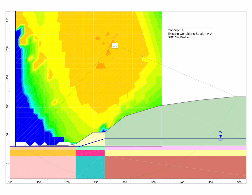
1.21.2
W
1.21.2
Concept CExisting Conditions Section A-ABBC Su Profile
250
200
150
100
500
100 150 200 250 300 350 400 450 500

Slide Analysis Information Document Name File Name: BBC_AA_Existing.sli Project Settings Project Title: SLIDE - An Interactive Slope Stability Program Failure Direction: Right to Left Units of Measurement: Imperial Units Pore Fluid Unit Weight: 62.4 lb/ft3 Groundwater Method: Water Surfaces Data Output: Standard Calculate Excess Pore Pressure: Off Allow Ru with Water Surfaces or Grids: Off Random Numbers: Pseudo-random Seed Random Number Seed: 10116 Random Number Generation Method: Park and Miller v.3 Analysis Methods Analysis Methods used: Bishop simplified Spencer Number of slices: 25 Tolerance: 0.005 Maximum number of iterations: 50 Surface Options Surface Type: Circular Search Method: Grid Search Radius increment: 10 Composite Surfaces: Disabled Reverse Curvature: Create Tension Crack Minimum Elevation: Not Defined Minimum Depth: Not Defined Material Properties Material: Existing Berm Strength Type: Mohr-Coulomb Unit Weight: 118.5 lb/ft3 Cohesion: 0 psf Friction Angle: 40 degrees Water Surface: Water Table Custom Hu value: 1 Material: Landfill Waste Strength Type: Mohr-Coulomb Unit Weight: 70 lb/ft3 Cohesion: 200 psf Friction Angle: 25 degrees
Water Surface: Water Table Custom Hu value: 1 Material: Clay Zone 1A Strength Type: Undrained Unit Weight: 115 lb/ft3 Cohesion Type: Constant Cohesion: 813 psf Water Surface: Water Table Custom Hu value: 0 Material: Clay Zone 1B Strength Type: Undrained Unit Weight: 115 lb/ft3 Cohesion Type: Constant Cohesion: 848 psf Water Surface: Water Table Custom Hu value: 0 Material: Clay Zone 1C Strength Type: Undrained Unit Weight: 115 lb/ft3 Cohesion Type: Constant Cohesion: 820 psf Water Surface: Water Table Custom Hu value: 0 Material: Clay Zone 2A Strength Type: Undrained Unit Weight: 115 lb/ft3 Cohesion Type: Constant Cohesion: 1120 psf Water Surface: Water Table Custom Hu value: 0 Material: Clay Zone 2B Strength Type: Undrained Unit Weight: 115 lb/ft3 Cohesion Type: Constant Cohesion: 1075 psf Water Surface: Water Table Custom Hu value: 0 Material: Clay Zone 2C Strength Type: Undrained Unit Weight: 115 lb/ft3 Cohesion Type: Constant Cohesion: 906 psf Water Surface: Water Table Custom Hu value: 0 Material: Clay Zone 3A Strength Type: Undrained Unit Weight: 115 lb/ft3 Cohesion Type: Constant Cohesion: 1267 psf Water Surface: Water Table

Custom Hu value: 0 Material: Clay Zone 3B Strength Type: Undrained Unit Weight: 115 lb/ft3 Cohesion Type: Constant Cohesion: 1181 psf Water Surface: Water Table Custom Hu value: 0 Material: Clay Zone 3C Strength Type: Undrained Unit Weight: 115 lb/ft3 Cohesion Type: Constant Cohesion: 1284 psf Water Surface: Water Table Custom Hu value: 0 List of All Coordinates Material Boundary 0.000 13.000 215.000 13.000 257.000 13.000 265.000 13.000 550.000 13.000 Material Boundary 0.000 23.000 215.000 23.000 257.000 23.000 265.000 23.000 550.000 23.000 Material Boundary 200.000 31.000 215.000 31.000 257.000 31.000 265.000 31.000 550.000 31.000 Material Boundary 265.000 -27.000 265.000 13.000 265.000 23.000 265.000 31.000 265.000 50.889 265.000 54.000 Material Boundary 215.000 -27.000 215.000 13.000 215.000 23.000 215.000 31.000 215.000 34.000

External Boundary 0.000 -27.000 215.000 -27.000 265.000 -27.000 550.000 -27.000 550.000 13.000 550.000 23.000 550.000 31.000 550.000 116.000 490.000 116.000 430.000 110.000 360.000 100.000 300.000 82.000 265.000 54.000 245.000 54.000 215.000 34.000 200.000 31.000 185.000 31.000 0.000 29.000 0.000 23.000 0.000 13.000 Water Table 0.000 29.000 220.000 29.000 265.000 43.000 550.000 43.000 Search Grid 108.979 29.000 364.630 29.000 364.630 284.651 108.979 284.651
1.21.2
W
W
1.21.2
Concept CProposed Section A-ABBC Su Profile
250
200
150
100
500
100 150 200 250 300 350 400 450

Slide Analysis Information Document Name File Name: BBC_AA_Proposed.sli Project Settings Project Title: SLIDE - An Interactive Slope Stability Program Failure Direction: Right to Left Units of Measurement: Imperial Units Pore Fluid Unit Weight: 62.4 lb/ft3 Groundwater Method: Water Surfaces Data Output: Standard Calculate Excess Pore Pressure: Off Allow Ru with Water Surfaces or Grids: Off Random Numbers: Pseudo-random Seed Random Number Seed: 10116 Random Number Generation Method: Park and Miller v.3 Analysis Methods Analysis Methods used: Bishop simplified Spencer Number of slices: 25 Tolerance: 0.005 Maximum number of iterations: 50 Surface Options Surface Type: Circular Search Method: Grid Search Radius increment: 10 Composite Surfaces: Disabled Reverse Curvature: Create Tension Crack Minimum Elevation: Not Defined Minimum Depth: Not Defined Material Properties Material: Existing Berm Strength Type: Mohr-Coulomb Unit Weight: 118.5 lb/ft3 Cohesion: 0 psf Friction Angle: 40 degrees Water Surface: Water Table Custom Hu value: 1 Material: Landfill Waste Strength Type: Mohr-Coulomb Unit Weight: 70 lb/ft3 Cohesion: 200 psf Friction Angle: 25 degrees

Water Surface: Water Table Custom Hu value: 1 Material: Clay Zone 1A Strength Type: Undrained Unit Weight: 115 lb/ft3 Cohesion Type: Constant Cohesion: 813 psf Water Surface: None Material: Clay Zone 1B Strength Type: Undrained Unit Weight: 115 lb/ft3 Cohesion Type: Constant Cohesion: 848 psf Water Surface: None Material: Clay Zone 1C Strength Type: Undrained Unit Weight: 115 lb/ft3 Cohesion Type: Constant Cohesion: 820 psf Water Surface: None Material: Clay Zone 2A Strength Type: Undrained Unit Weight: 115 lb/ft3 Cohesion Type: Constant Cohesion: 1120 psf Water Surface: None Material: Clay Zone 2B Strength Type: Undrained Unit Weight: 115 lb/ft3 Cohesion Type: Constant Cohesion: 1075 psf Water Surface: None Material: Clay Zone 2C Strength Type: Undrained Unit Weight: 115 lb/ft3 Cohesion Type: Constant Cohesion: 906 psf Water Surface: None Material: Clay Zone 3A Strength Type: Undrained Unit Weight: 115 lb/ft3 Cohesion Type: Constant Cohesion: 1267 psf Water Surface: None Material: Clay Zone 3B Strength Type: Undrained Unit Weight: 115 lb/ft3 Cohesion Type: Constant Cohesion: 1181 psf

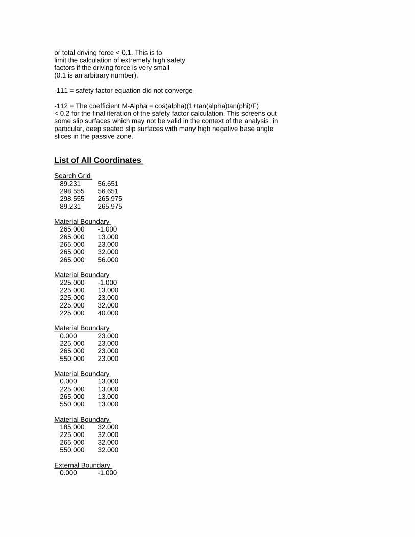
Water Surface: None Material: Clay Zone 3C Strength Type: Undrained Unit Weight: 115 lb/ft3 Cohesion Type: Constant Cohesion: 1284 psf Water Surface: None Material: Structural Fill Strength Type: Mohr-Coulomb Unit Weight: 130 lb/ft3 Cohesion: 0 psf Friction Angle: 40 degrees Water Surface: Water Table Custom Hu value: 1 Global Minimums Method: bishop simplified FS: 1.202940 Center: 245.326, 207.956 Radius: 234.643 Left Slip Surface Endpoint: 91.911, 30.414 Right Slip Surface Endpoint: 460.498, 114.369 Resisting Moment=1.06547e+008 lb-ft Driving Moment=8.85724e+007 lb-ft Method: spencer FS: 1.188670 Center: 245.326, 207.956 Radius: 234.643 Left Slip Surface Endpoint: 91.911, 30.414 Right Slip Surface Endpoint: 460.498, 114.369 Resisting Moment=1.05283e+008 lb-ft Driving Moment=8.85724e+007 lb-ft Resisting Horizontal Force=383529 lb Driving Horizontal Force=322654 lb Valid / Invalid Surfaces Method: bishop simplified Number of Valid Surfaces: 6636 Number of Invalid Surfaces: 3935 Error Codes: Error Code -103 reported for 3597 surfaces Error Code -112 reported for 338 surfaces Method: spencer Number of Valid Surfaces: 6378 Number of Invalid Surfaces: 4193 Error Codes: Error Code -103 reported for 3597 surfaces Error Code -108 reported for 124 surfaces Error Code -111 reported for 110 surfaces Error Code -112 reported for 362 surfaces
Error Codes The following errors were encountered during the computation: -103 = Two surface / slope intersections, but one or more surface / nonslope external polygon intersections lie between them. This usually occurs when the slip surface extends past the bottom of the soil region, but may also occur on a benched slope model with two sets of Slope Limits. -108 = Total driving moment or total driving force < 0.1. This is to limit the calculation of extremely high safety factors if the driving force is very small (0.1 is an arbitrary number). -111 = safety factor equation did not converge -112 = The coefficient M-Alpha = cos(alpha)(1+tan(alpha)tan(phi)/F) < 0.2 for the final iteration of the safety factor calculation. This screens out some slip surfaces which may not be valid in the context of the analysis, in particular, deep seated slip surfaces with many high negative base angle slices in the passive zone. List of All Coordinates Search Grid 108.979 29.000 364.630 29.000 364.630 284.651 108.979 284.651 Material Boundary 0.000 13.000 200.000 13.000 257.000 13.000 265.000 13.000 550.000 13.000 Material Boundary 0.000 23.000 200.000 23.000 257.000 23.000 265.000 23.000 550.000 23.000 Material Boundary 200.000 23.000 200.000 31.000 Material Boundary 200.000 -27.000 200.000 13.000

200.000 23.000 Material Boundary 200.000 31.000 257.000 31.000 265.000 31.000 550.000 31.000 Material Boundary 265.000 54.000 300.000 82.000 332.759 91.828 360.000 100.000 430.000 110.000 490.000 116.000 550.000 116.000 Material Boundary 265.000 -27.000 265.000 13.000 265.000 23.000 265.000 31.000 265.000 54.000 Material Boundary 195.000 32.000 195.000 31.000 200.000 31.000 Material Boundary 195.000 32.000 212.000 34.000 245.000 54.000 265.000 54.000 External Boundary 0.000 -27.000 200.000 -27.000 265.000 -27.000 550.000 -27.000 550.000 13.000 550.000 23.000 550.000 31.000 550.000 116.000 550.000 118.000 490.000 118.000 425.000 110.000 350.000 100.000 305.000 86.500 195.000 32.000 0.000 29.000 0.000 23.000 0.000 13.000 Water Table 0.000 29.000
220.000 29.000 265.000 43.000 550.000 43.000
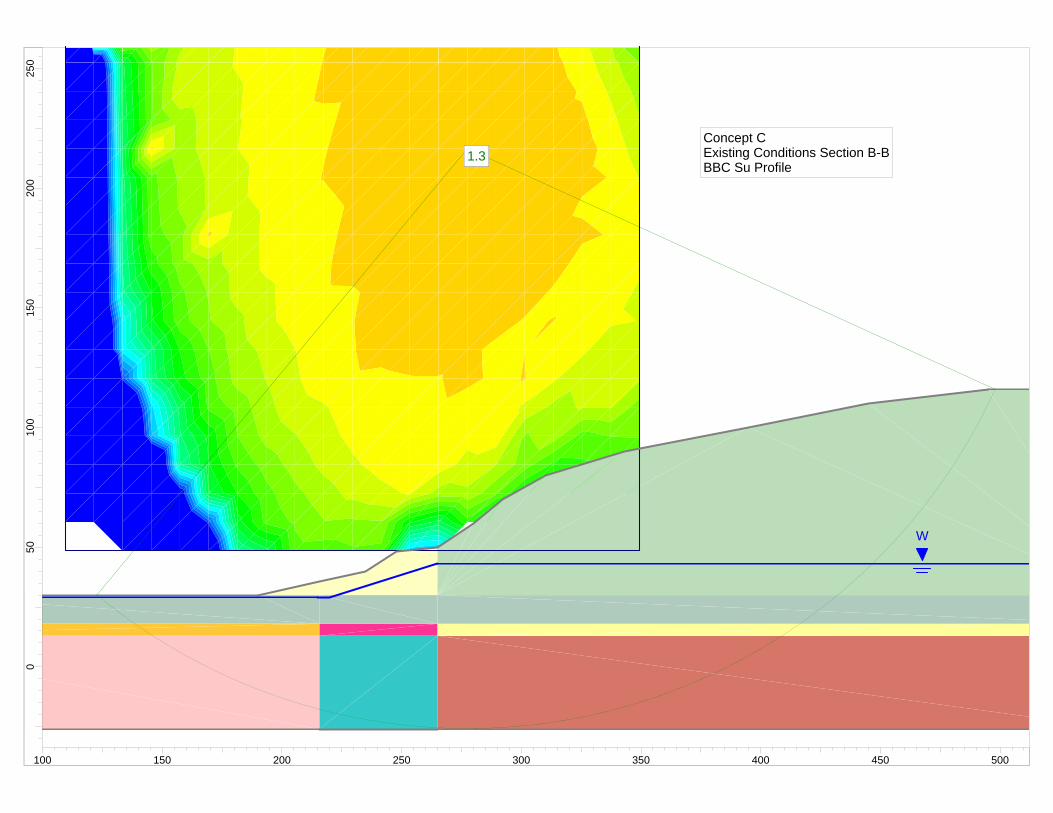
1.31.3
W
1.31.3Concept CExisting Conditions Section B-BBBC Su Profile
250
200
150
100
500
100 150 200 250 300 350 400 450 500

Slide Analysis Information Document Name File Name: BBC_BB_Existing.sli Project Settings Project Title: SLIDE - An Interactive Slope Stability Program Failure Direction: Right to Left Units of Measurement: Imperial Units Pore Fluid Unit Weight: 62.4 lb/ft3 Groundwater Method: Water Surfaces Data Output: Standard Calculate Excess Pore Pressure: Off Allow Ru with Water Surfaces or Grids: Off Random Numbers: Pseudo-random Seed Random Number Seed: 10116 Random Number Generation Method: Park and Miller v.3 Analysis Methods Analysis Methods used: Bishop simplified Spencer Number of slices: 25 Tolerance: 0.005 Maximum number of iterations: 50 Surface Options Surface Type: Circular Search Method: Grid Search Radius increment: 10 Composite Surfaces: Disabled Reverse Curvature: Create Tension Crack Minimum Elevation: Not Defined Minimum Depth: Not Defined Material Properties Material: Existing Berm Strength Type: Mohr-Coulomb Unit Weight: 118.5 lb/ft3 Cohesion: 0 psf Friction Angle: 40 degrees Water Surface: Water Table Custom Hu value: 1 Material: Landfill Waste Strength Type: Mohr-Coulomb Unit Weight: 70 lb/ft3 Cohesion: 200 psf Friction Angle: 25 degrees

Water Surface: Water Table Custom Hu value: 1 Material: Clay Zone 1B Strength Type: Undrained Unit Weight: 115 lb/ft3 Cohesion Type: Constant Cohesion: 848 psf Water Surface: None Material: Clay Zone 1C Strength Type: Undrained Unit Weight: 115 lb/ft3 Cohesion Type: Constant Cohesion: 820 psf Water Surface: None Material: Clay Zone 2B Strength Type: Undrained Unit Weight: 115 lb/ft3 Cohesion Type: Constant Cohesion: 1075 psf Water Surface: None Material: Clay Zone 2C Strength Type: Undrained Unit Weight: 115 lb/ft3 Cohesion Type: Constant Cohesion: 906 psf Water Surface: None Material: Clay Zone 3B Strength Type: Undrained Unit Weight: 115 lb/ft3 Cohesion Type: Constant Cohesion: 1181 psf Water Surface: None Material: Clay Zone 3C Strength Type: Undrained Unit Weight: 115 lb/ft3 Cohesion Type: Constant Cohesion: 1284 psf Water Surface: None Material: Fill Strength Type: Mohr-Coulomb Unit Weight: 118.5 lb/ft3 Cohesion: 0 psf Friction Angle: 30 degrees Water Surface: Water Table Custom Hu value: 1 Global Minimums Method: bishop simplified FS: 1.308700
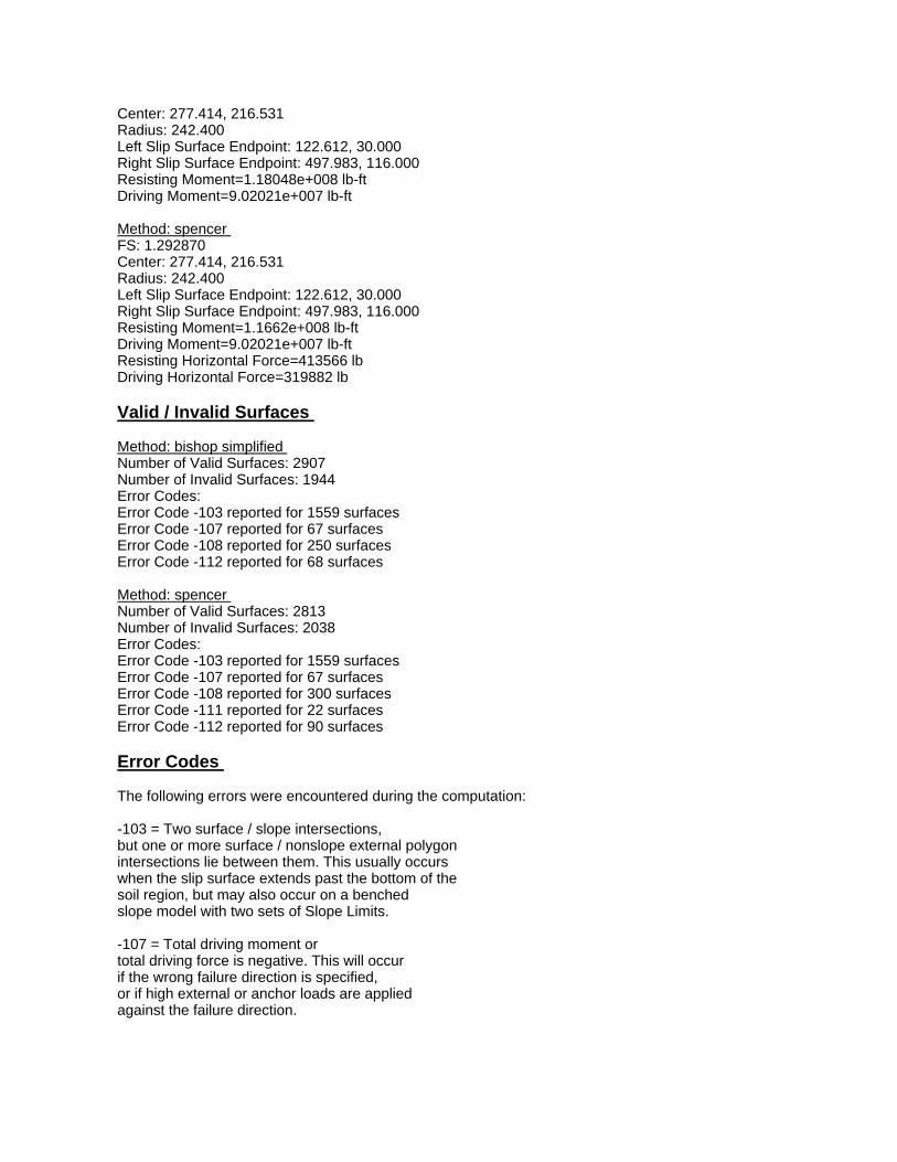
Center: 277.414, 216.531 Radius: 242.400 Left Slip Surface Endpoint: 122.612, 30.000 Right Slip Surface Endpoint: 497.983, 116.000 Resisting Moment=1.18048e+008 lb-ft Driving Moment=9.02021e+007 lb-ft Method: spencer FS: 1.292870 Center: 277.414, 216.531 Radius: 242.400 Left Slip Surface Endpoint: 122.612, 30.000 Right Slip Surface Endpoint: 497.983, 116.000 Resisting Moment=1.1662e+008 lb-ft Driving Moment=9.02021e+007 lb-ft Resisting Horizontal Force=413566 lb Driving Horizontal Force=319882 lb Valid / Invalid Surfaces Method: bishop simplified Number of Valid Surfaces: 2907 Number of Invalid Surfaces: 1944 Error Codes: Error Code -103 reported for 1559 surfaces Error Code -107 reported for 67 surfaces Error Code -108 reported for 250 surfaces Error Code -112 reported for 68 surfaces Method: spencer Number of Valid Surfaces: 2813 Number of Invalid Surfaces: 2038 Error Codes: Error Code -103 reported for 1559 surfaces Error Code -107 reported for 67 surfaces Error Code -108 reported for 300 surfaces Error Code -111 reported for 22 surfaces Error Code -112 reported for 90 surfaces Error Codes The following errors were encountered during the computation: -103 = Two surface / slope intersections, but one or more surface / nonslope external polygon intersections lie between them. This usually occurs when the slip surface extends past the bottom of the soil region, but may also occur on a benched slope model with two sets of Slope Limits. -107 = Total driving moment or total driving force is negative. This will occur if the wrong failure direction is specified, or if high external or anchor loads are applied against the failure direction.

-108 = Total driving moment or total driving force < 0.1. This is to limit the calculation of extremely high safety factors if the driving force is very small (0.1 is an arbitrary number). -111 = safety factor equation did not converge -112 = The coefficient M-Alpha = cos(alpha)(1+tan(alpha)tan(phi)/F) < 0.2 for the final iteration of the safety factor calculation. This screens out some slip surfaces which may not be valid in the context of the analysis, in particular, deep seated slip surfaces with many high negative base angle slices in the passive zone. List of All Coordinates Search Grid 109.391 48.509 349.423 48.509 349.423 288.541 109.391 288.541 Material Boundary 0.000 18.000 215.664 18.000 265.000 18.000 550.000 18.000 Material Boundary 0.000 13.000 215.664 13.000 265.000 13.000 550.000 13.000 Material Boundary 265.000 -26.000 265.000 13.000 265.000 18.000 265.000 30.000 265.000 50.000 Material Boundary 215.664 -26.000 215.664 13.000 215.664 18.000 215.664 30.000 215.664 35.703 Material Boundary 190.000 30.000 215.664 30.000 265.000 30.000 550.000 30.000 External Boundary

0.000 -26.000 215.664 -26.000 265.000 -26.000 550.000 -26.000 550.000 13.000 550.000 18.000 550.000 30.000 550.000 116.000 495.000 116.000 445.000 110.000 395.000 100.000 343.000 90.000 310.000 80.000 292.000 70.000 280.000 60.000 265.000 50.000 248.000 48.000 235.000 40.000 215.664 35.703 190.000 30.000 45.000 30.000 0.000 31.000 0.000 18.000 0.000 13.000 Water Table 0.000 29.000 215.000 29.000 220.000 29.000 265.000 43.000 550.000 43.000
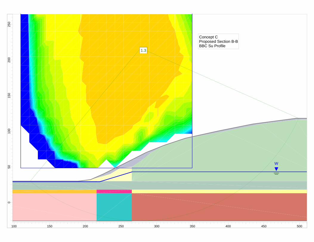
1.31.3
W
1.31.3
Concept CProposed Section B-BBBC Su Profile
250
200
150
100
500
100 150 200 250 300 350 400 450 500

Slide Analysis Information Document Name File Name: BBC_BB_Proposed.sli Project Settings Project Title: SLIDE - An Interactive Slope Stability Program Failure Direction: Right to Left Units of Measurement: Imperial Units Pore Fluid Unit Weight: 62.4 lb/ft3 Groundwater Method: Water Surfaces Data Output: Standard Calculate Excess Pore Pressure: Off Allow Ru with Water Surfaces or Grids: Off Random Numbers: Pseudo-random Seed Random Number Seed: 10116 Random Number Generation Method: Park and Miller v.3 Analysis Methods Analysis Methods used: Bishop simplified Spencer Number of slices: 25 Tolerance: 0.005 Maximum number of iterations: 50 Surface Options Surface Type: Circular Search Method: Grid Search Radius increment: 10 Composite Surfaces: Disabled Reverse Curvature: Create Tension Crack Minimum Elevation: Not Defined Minimum Depth: Not Defined Material Properties Material: Existing Berm Strength Type: Mohr-Coulomb Unit Weight: 118.5 lb/ft3 Cohesion: 0 psf Friction Angle: 40 degrees Water Surface: Water Table Custom Hu value: 1 Material: Landfill Waste Strength Type: Mohr-Coulomb Unit Weight: 70 lb/ft3 Cohesion: 200 psf Friction Angle: 25 degrees

Water Surface: Water Table Custom Hu value: 1 Material: Clay Zone 1B Strength Type: Undrained Unit Weight: 115 lb/ft3 Cohesion Type: Constant Cohesion: 848 psf Water Surface: None Material: Clay Zone 1C Strength Type: Undrained Unit Weight: 115 lb/ft3 Cohesion Type: Constant Cohesion: 820 psf Water Surface: None Material: Clay Zone 2B Strength Type: Undrained Unit Weight: 115 lb/ft3 Cohesion Type: Constant Cohesion: 1075 psf Water Surface: None Material: Clay Zone 2C Strength Type: Undrained Unit Weight: 115 lb/ft3 Cohesion Type: Constant Cohesion: 906 psf Water Surface: None Material: Clay Zone 3B Strength Type: Undrained Unit Weight: 115 lb/ft3 Cohesion Type: Constant Cohesion: 1181 psf Water Surface: None Material: Clay Zone 3C Strength Type: Undrained Unit Weight: 115 lb/ft3 Cohesion Type: Constant Cohesion: 1284 psf Water Surface: None Material: Structural Fill Strength Type: Mohr-Coulomb Unit Weight: 130 lb/ft3 Cohesion: 0 psf Friction Angle: 40 degrees Water Surface: Water Table Custom Hu value: 1 Material: Fill Strength Type: Mohr-Coulomb Unit Weight: 118.5 lb/ft3 Cohesion: 0 psf
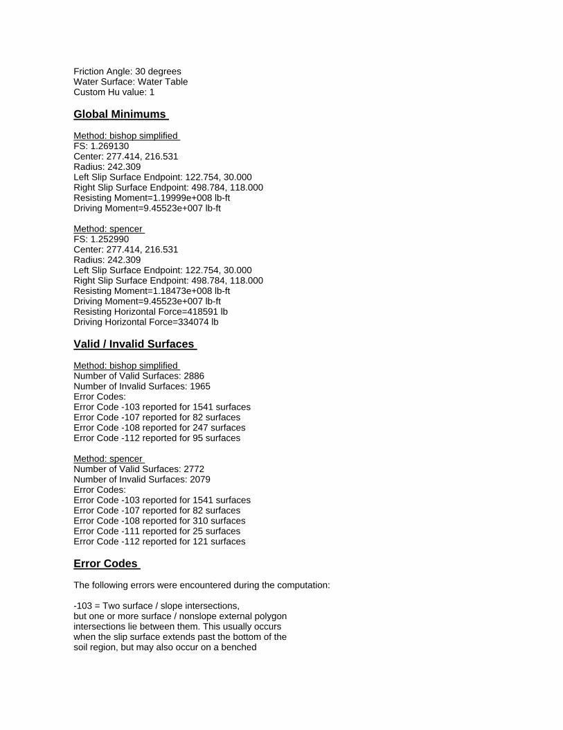
Friction Angle: 30 degrees Water Surface: Water Table Custom Hu value: 1 Global Minimums Method: bishop simplified FS: 1.269130 Center: 277.414, 216.531 Radius: 242.309 Left Slip Surface Endpoint: 122.754, 30.000 Right Slip Surface Endpoint: 498.784, 118.000 Resisting Moment=1.19999e+008 lb-ft Driving Moment=9.45523e+007 lb-ft Method: spencer FS: 1.252990 Center: 277.414, 216.531 Radius: 242.309 Left Slip Surface Endpoint: 122.754, 30.000 Right Slip Surface Endpoint: 498.784, 118.000 Resisting Moment=1.18473e+008 lb-ft Driving Moment=9.45523e+007 lb-ft Resisting Horizontal Force=418591 lb Driving Horizontal Force=334074 lb Valid / Invalid Surfaces Method: bishop simplified Number of Valid Surfaces: 2886 Number of Invalid Surfaces: 1965 Error Codes: Error Code -103 reported for 1541 surfaces Error Code -107 reported for 82 surfaces Error Code -108 reported for 247 surfaces Error Code -112 reported for 95 surfaces Method: spencer Number of Valid Surfaces: 2772 Number of Invalid Surfaces: 2079 Error Codes: Error Code -103 reported for 1541 surfaces Error Code -107 reported for 82 surfaces Error Code -108 reported for 310 surfaces Error Code -111 reported for 25 surfaces Error Code -112 reported for 121 surfaces Error Codes The following errors were encountered during the computation: -103 = Two surface / slope intersections, but one or more surface / nonslope external polygon intersections lie between them. This usually occurs when the slip surface extends past the bottom of the soil region, but may also occur on a benched

slope model with two sets of Slope Limits. -107 = Total driving moment or total driving force is negative. This will occur if the wrong failure direction is specified, or if high external or anchor loads are applied against the failure direction. -108 = Total driving moment or total driving force < 0.1. This is to limit the calculation of extremely high safety factors if the driving force is very small (0.1 is an arbitrary number). -111 = safety factor equation did not converge -112 = The coefficient M-Alpha = cos(alpha)(1+tan(alpha)tan(phi)/F) < 0.2 for the final iteration of the safety factor calculation. This screens out some slip surfaces which may not be valid in the context of the analysis, in particular, deep seated slip surfaces with many high negative base angle slices in the passive zone. List of All Coordinates Search Grid 109.391 48.509 349.423 48.509 349.423 288.541 109.391 288.541 Material Boundary 0.000 18.000 215.664 18.000 265.000 18.000 550.000 18.000 Material Boundary 0.000 13.000 215.664 13.000 265.000 13.000 550.000 13.000 Material Boundary 265.000 -26.000 265.000 13.000 265.000 18.000 265.000 30.000 265.000 50.000 265.000 60.000 Material Boundary 190.000 30.000 215.664 30.000 265.000 30.000 550.000 30.000

Material Boundary 207.000 32.000 215.664 34.475 235.000 40.000 248.000 48.000 265.000 50.000 280.000 60.000 292.000 70.000 310.000 80.000 343.000 90.000 395.000 100.000 445.000 110.000 495.000 116.000 550.000 116.000 Material Boundary 215.664 -26.000 215.664 13.000 215.664 18.000 215.664 30.000 215.664 34.475 External Boundary 0.000 -26.000 215.664 -26.000 265.000 -26.000 550.000 -26.000 550.000 13.000 550.000 18.000 550.000 30.000 550.000 116.000 550.000 118.000 495.000 118.000 435.000 110.000 385.000 100.000 340.000 90.000 310.000 80.000 285.000 70.000 265.000 60.000 245.000 50.000 225.000 40.000 207.000 32.000 190.000 30.000 45.000 30.000 0.000 31.000 0.000 18.000 0.000 13.000 Water Table 0.000 29.000 215.000 29.000 220.000 29.000 265.000 43.000 550.000 43.000

1.41.4
W
W
1.41.4
Concept CExisting Conditions Section C-CBBC Su Profile
250
200
150
100
500
100 150 200 250 300 350 400 450 500

Slide Analysis Information Document Name File Name: BBC_CC_Existing.sli Project Settings Project Title: SLIDE - An Interactive Slope Stability Program Failure Direction: Right to Left Units of Measurement: Imperial Units Pore Fluid Unit Weight: 62.4 lb/ft3 Groundwater Method: Water Surfaces Data Output: Standard Calculate Excess Pore Pressure: Off Allow Ru with Water Surfaces or Grids: Off Random Numbers: Pseudo-random Seed Random Number Seed: 10116 Random Number Generation Method: Park and Miller v.3 Analysis Methods Analysis Methods used: Bishop simplified Spencer Number of slices: 25 Tolerance: 0.005 Maximum number of iterations: 50 Surface Options Surface Type: Circular Search Method: Grid Search Radius increment: 10 Composite Surfaces: Disabled Reverse Curvature: Create Tension Crack Minimum Elevation: Not Defined Minimum Depth: Not Defined Material Properties Material: Existing Berm Strength Type: Mohr-Coulomb Unit Weight: 118.5 lb/ft3 Cohesion: 0 psf Friction Angle: 40 degrees Water Surface: Water Table Custom Hu value: 1 Material: Landfill Waste Strength Type: Mohr-Coulomb Unit Weight: 70 lb/ft3 Cohesion: 200 psf Friction Angle: 25 degrees

Water Surface: Water Table Custom Hu value: 1 Material: Clay Zone 1B Strength Type: Undrained Unit Weight: 115 lb/ft3 Cohesion Type: Constant Cohesion: 848 psf Water Surface: None Material: Clay Zone 1C Strength Type: Undrained Unit Weight: 115 lb/ft3 Cohesion Type: Constant Cohesion: 820 psf Water Surface: None Material: Clay Zone 2B Strength Type: Undrained Unit Weight: 115 lb/ft3 Cohesion Type: Constant Cohesion: 1075 psf Water Surface: None Material: Clay Zone 2C Strength Type: Undrained Unit Weight: 115 lb/ft3 Cohesion Type: Constant Cohesion: 906 psf Water Surface: None Material: Clay Zone 3B Strength Type: Undrained Unit Weight: 115 lb/ft3 Cohesion Type: Constant Cohesion: 1181 psf Water Surface: None Material: Clay Zone 3C Strength Type: Undrained Unit Weight: 115 lb/ft3 Cohesion Type: Constant Cohesion: 1284 psf Water Surface: None Material: Fill Strength Type: Mohr-Coulomb Unit Weight: 118.5 lb/ft3 Cohesion: 0 psf Friction Angle: 30 degrees Water Surface: Water Table Custom Hu value: 1 Global Minimums Method: bishop simplified FS: 1.438870
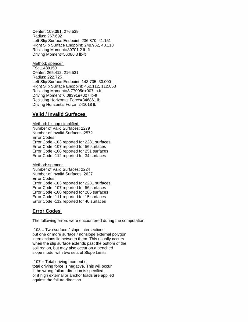
Center: 109.391, 276.539 Radius: 267.692 Left Slip Surface Endpoint: 236.870, 41.151 Right Slip Surface Endpoint: 248.962, 48.113 Resisting Moment=80701.2 lb-ft Driving Moment=56086.3 lb-ft Method: spencer FS: 1.439150 Center: 265.412, 216.531 Radius: 222.725 Left Slip Surface Endpoint: 143.705, 30.000 Right Slip Surface Endpoint: 462.112, 112.053 Resisting Moment=8.77005e+007 lb-ft Driving Moment=6.09391e+007 lb-ft Resisting Horizontal Force=346861 lb Driving Horizontal Force=241018 lb Valid / Invalid Surfaces Method: bishop simplified Number of Valid Surfaces: 2279 Number of Invalid Surfaces: 2572 Error Codes: Error Code -103 reported for 2231 surfaces Error Code -107 reported for 56 surfaces Error Code -108 reported for 251 surfaces Error Code -112 reported for 34 surfaces Method: spencer Number of Valid Surfaces: 2224 Number of Invalid Surfaces: 2627 Error Codes: Error Code -103 reported for 2231 surfaces Error Code -107 reported for 56 surfaces Error Code -108 reported for 285 surfaces Error Code -111 reported for 15 surfaces Error Code -112 reported for 40 surfaces Error Codes The following errors were encountered during the computation: -103 = Two surface / slope intersections, but one or more surface / nonslope external polygon intersections lie between them. This usually occurs when the slip surface extends past the bottom of the soil region, but may also occur on a benched slope model with two sets of Slope Limits. -107 = Total driving moment or total driving force is negative. This will occur if the wrong failure direction is specified, or if high external or anchor loads are applied against the failure direction.

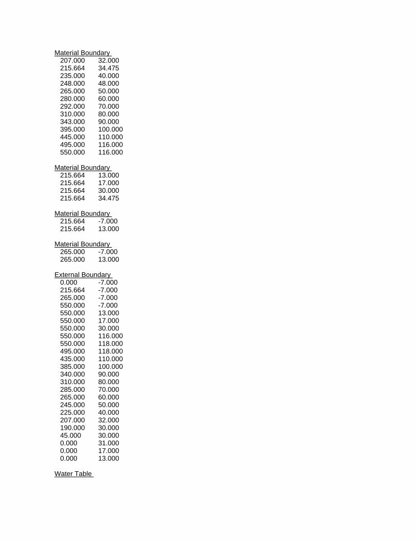
-108 = Total driving moment or total driving force < 0.1. This is to limit the calculation of extremely high safety factors if the driving force is very small (0.1 is an arbitrary number). -111 = safety factor equation did not converge -112 = The coefficient M-Alpha = cos(alpha)(1+tan(alpha)tan(phi)/F) < 0.2 for the final iteration of the safety factor calculation. This screens out some slip surfaces which may not be valid in the context of the analysis, in particular, deep seated slip surfaces with many high negative base angle slices in the passive zone. List of All Coordinates Search Grid 109.391 48.509 349.423 48.509 349.423 288.541 109.391 288.541 Material Boundary 265.000 17.000 550.000 18.000 Material Boundary 0.000 13.000 215.664 13.000 265.000 13.000 550.000 13.000 Material Boundary 265.000 -7.000 265.000 13.000 265.000 17.000 265.000 30.000 265.000 50.000 Material Boundary 215.664 -7.000 215.664 13.000 215.664 17.000 215.664 30.000 215.664 35.703 Material Boundary 190.000 30.000 215.664 30.000 265.000 30.000 550.000 30.000 Material Boundary 0.000 17.000 215.664 17.000

265.000 17.000 550.000 17.000 External Boundary 215.664 -7.000 265.000 -7.000 550.000 -7.000 550.000 13.000 550.000 17.000 550.000 18.000 550.000 30.000 550.000 116.000 495.000 116.000 445.000 110.000 395.000 100.000 343.000 90.000 310.000 80.000 292.000 70.000 280.000 60.000 265.000 50.000 248.000 48.000 235.000 40.000 215.664 35.703 190.000 30.000 45.000 30.000 0.000 31.000 0.000 17.000 0.000 13.000 0.000 -7.000 Water Table 0.000 29.000 215.000 29.000 220.000 29.000 265.000 43.000 550.000 43.000

1.41.4
W
W
1.41.4
Concept CProposed Section C-CBBC Su Profile
250
200
150
100
500
100 150 200 250 300 350 400 450

Slide Analysis Information Document Name File Name: BBC_CC_Proposed.sli Project Settings Project Title: SLIDE - An Interactive Slope Stability Program Failure Direction: Right to Left Units of Measurement: Imperial Units Pore Fluid Unit Weight: 62.4 lb/ft3 Groundwater Method: Water Surfaces Data Output: Standard Calculate Excess Pore Pressure: Off Allow Ru with Water Surfaces or Grids: Off Random Numbers: Pseudo-random Seed Random Number Seed: 10116 Random Number Generation Method: Park and Miller v.3 Analysis Methods Analysis Methods used: Bishop simplified Spencer Number of slices: 25 Tolerance: 0.005 Maximum number of iterations: 50 Surface Options Surface Type: Circular Search Method: Grid Search Radius increment: 10 Composite Surfaces: Disabled Reverse Curvature: Create Tension Crack Minimum Elevation: Not Defined Minimum Depth: Not Defined Material Properties Material: Existing Berm Strength Type: Mohr-Coulomb Unit Weight: 118.5 lb/ft3 Cohesion: 0 psf Friction Angle: 40 degrees Water Surface: Water Table Custom Hu value: 1 Material: Landfill Waste Strength Type: Mohr-Coulomb Unit Weight: 70 lb/ft3 Cohesion: 200 psf Friction Angle: 25 degrees

Water Surface: Water Table Custom Hu value: 1 Material: Clay Zone 1B Strength Type: Undrained Unit Weight: 115 lb/ft3 Cohesion Type: Constant Cohesion: 848 psf Water Surface: None Material: Clay Zone 1C Strength Type: Undrained Unit Weight: 115 lb/ft3 Cohesion Type: Constant Cohesion: 820 psf Water Surface: None Material: Clay Zone 2B Strength Type: Undrained Unit Weight: 115 lb/ft3 Cohesion Type: Constant Cohesion: 1075 psf Water Surface: None Material: Clay Zone 2C Strength Type: Undrained Unit Weight: 115 lb/ft3 Cohesion Type: Constant Cohesion: 906 psf Water Surface: None Material: Clay Zone 3B Strength Type: Undrained Unit Weight: 115 lb/ft3 Cohesion Type: Constant Cohesion: 1181 psf Water Surface: None Material: Clay Zone 3C Strength Type: Undrained Unit Weight: 115 lb/ft3 Cohesion Type: Constant Cohesion: 1284 psf Water Surface: None Material: Structural Fill Strength Type: Mohr-Coulomb Unit Weight: 130 lb/ft3 Cohesion: 0 psf Friction Angle: 40 degrees Water Surface: Water Table Custom Hu value: 1 Material: Fill Strength Type: Mohr-Coulomb Unit Weight: 118.5 lb/ft3 Cohesion: 0 psf

Friction Angle: 30 degrees Water Surface: Water Table Custom Hu value: 1 Global Minimums Method: bishop simplified FS: 1.415760 Center: 265.412, 216.531 Radius: 222.724 Left Slip Surface Endpoint: 143.708, 30.000 Right Slip Surface Endpoint: 462.993, 113.732 Resisting Moment=9.15754e+007 lb-ft Driving Moment=6.46831e+007 lb-ft Method: spencer FS: 1.386900 Center: 265.412, 216.531 Radius: 222.724 Left Slip Surface Endpoint: 143.708, 30.000 Right Slip Surface Endpoint: 462.993, 113.732 Resisting Moment=8.97091e+007 lb-ft Driving Moment=6.46831e+007 lb-ft Resisting Horizontal Force=353549 lb Driving Horizontal Force=254920 lb Valid / Invalid Surfaces Method: bishop simplified Number of Valid Surfaces: 2267 Number of Invalid Surfaces: 2584 Error Codes: Error Code -103 reported for 2214 surfaces Error Code -107 reported for 70 surfaces Error Code -108 reported for 248 surfaces Error Code -112 reported for 52 surfaces Method: spencer Number of Valid Surfaces: 2202 Number of Invalid Surfaces: 2649 Error Codes: Error Code -103 reported for 2214 surfaces Error Code -107 reported for 70 surfaces Error Code -108 reported for 290 surfaces Error Code -111 reported for 14 surfaces Error Code -112 reported for 61 surfaces Error Codes The following errors were encountered during the computation: -103 = Two surface / slope intersections, but one or more surface / nonslope external polygon intersections lie between them. This usually occurs when the slip surface extends past the bottom of the soil region, but may also occur on a benched

slope model with two sets of Slope Limits. -107 = Total driving moment or total driving force is negative. This will occur if the wrong failure direction is specified, or if high external or anchor loads are applied against the failure direction. -108 = Total driving moment or total driving force < 0.1. This is to limit the calculation of extremely high safety factors if the driving force is very small (0.1 is an arbitrary number). -111 = safety factor equation did not converge -112 = The coefficient M-Alpha = cos(alpha)(1+tan(alpha)tan(phi)/F) < 0.2 for the final iteration of the safety factor calculation. This screens out some slip surfaces which may not be valid in the context of the analysis, in particular, deep seated slip surfaces with many high negative base angle slices in the passive zone. List of All Coordinates Search Grid 109.391 48.509 349.423 48.509 349.423 288.541 109.391 288.541 Material Boundary 0.000 17.000 215.664 17.000 265.000 17.000 550.000 17.000 Material Boundary 0.000 13.000 215.664 13.000 265.000 13.000 550.000 13.000 Material Boundary 265.000 13.000 265.000 17.000 265.000 30.000 265.000 50.000 265.000 60.000 Material Boundary 190.000 30.000 215.664 30.000 265.000 30.000 550.000 30.000
Material Boundary 207.000 32.000 215.664 34.475 235.000 40.000 248.000 48.000 265.000 50.000 280.000 60.000 292.000 70.000 310.000 80.000 343.000 90.000 395.000 100.000 445.000 110.000 495.000 116.000 550.000 116.000 Material Boundary 215.664 13.000 215.664 17.000 215.664 30.000 215.664 34.475 Material Boundary 215.664 -7.000 215.664 13.000 Material Boundary 265.000 -7.000 265.000 13.000 External Boundary 0.000 -7.000 215.664 -7.000 265.000 -7.000 550.000 -7.000 550.000 13.000 550.000 17.000 550.000 30.000 550.000 116.000 550.000 118.000 495.000 118.000 435.000 110.000 385.000 100.000 340.000 90.000 310.000 80.000 285.000 70.000 265.000 60.000 245.000 50.000 225.000 40.000 207.000 32.000 190.000 30.000 45.000 30.000 0.000 31.000 0.000 17.000 0.000 13.000 Water Table
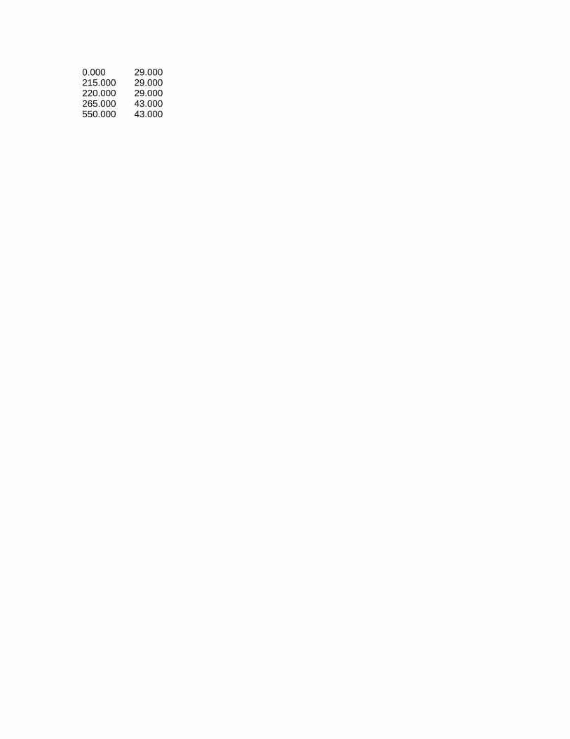
0.000 29.000 215.000 29.000 220.000 29.000 265.000 43.000 550.000 43.000

1.31.3
W
W
1.31.3
Concept CExisting Conditions Section D-DBBC Su Profile
*Note that the minimum FS for the deepslip circle is 1.4.
250
200
150
100
500
100 150 200 250 300 350 400 450

Slide Analysis Information Document Name File Name: BBC_DD_Existing.sli Project Settings Project Title: SLIDE - An Interactive Slope Stability Program Failure Direction: Right to Left Units of Measurement: Imperial Units Pore Fluid Unit Weight: 62.4 lb/ft3 Groundwater Method: Water Surfaces Data Output: Standard Calculate Excess Pore Pressure: Off Allow Ru with Water Surfaces or Grids: Off Random Numbers: Pseudo-random Seed Random Number Seed: 10116 Random Number Generation Method: Park and Miller v.3 Analysis Methods Analysis Methods used: Bishop simplified Spencer Number of slices: 25 Tolerance: 0.005 Maximum number of iterations: 50 Surface Options Surface Type: Circular Search Method: Grid Search Radius increment: 10 Composite Surfaces: Disabled Reverse Curvature: Create Tension Crack Minimum Elevation: Not Defined Minimum Depth: Not Defined Material Properties Material: Existing Berm Strength Type: Mohr-Coulomb Unit Weight: 118.5 lb/ft3 Cohesion: 0 psf Friction Angle: 40 degrees Water Surface: Water Table Custom Hu value: 1 Material: Landfill Waste Strength Type: Mohr-Coulomb Unit Weight: 70 lb/ft3 Cohesion: 200 psf Friction Angle: 25 degrees

Water Surface: Water Table Custom Hu value: 1 Material: Clay Zone 1B Strength Type: Undrained Unit Weight: 115 lb/ft3 Cohesion Type: Constant Cohesion: 848 psf Water Surface: None Material: Clay Zone 1C Strength Type: Undrained Unit Weight: 115 lb/ft3 Cohesion Type: Constant Cohesion: 820 psf Water Surface: None Material: Clay Zone 2B Strength Type: Undrained Unit Weight: 115 lb/ft3 Cohesion Type: Constant Cohesion: 1075 psf Water Surface: None Material: Clay Zone 2C Strength Type: Undrained Unit Weight: 115 lb/ft3 Cohesion Type: Constant Cohesion: 906 psf Water Surface: None Material: Clay Zone 3B Strength Type: Undrained Unit Weight: 115 lb/ft3 Cohesion Type: Constant Cohesion: 1181 psf Water Surface: None Material: Clay Zone 3C Strength Type: Undrained Unit Weight: 115 lb/ft3 Cohesion Type: Constant Cohesion: 1284 psf Water Surface: None Material: Fill Strength Type: Mohr-Coulomb Unit Weight: 118.5 lb/ft3 Cohesion: 0 psf Friction Angle: 30 degrees Water Surface: Water Table Custom Hu value: 1 Global Minimums Method: bishop simplified FS: 1.319630

Center: 152.028, 182.245 Radius: 159.385 Left Slip Surface Endpoint: 230.735, 43.649 Right Slip Surface Endpoint: 244.245, 52.247 Resisting Moment=28686.2 lb-ft Driving Moment=21738 lb-ft Method: spencer FS: 1.319530 Center: 152.028, 182.245 Radius: 159.385 Left Slip Surface Endpoint: 230.735, 43.649 Right Slip Surface Endpoint: 244.245, 52.247 Resisting Moment=28684 lb-ft Driving Moment=21738 lb-ft Resisting Horizontal Force=151.9 lb Driving Horizontal Force=115.117 lb Valid / Invalid Surfaces Method: bishop simplified Number of Valid Surfaces: 2376 Number of Invalid Surfaces: 2475 Error Codes: Error Code -103 reported for 2464 surfaces Error Code -106 reported for 1 surface Error Code -112 reported for 10 surfaces Method: spencer Number of Valid Surfaces: 2355 Number of Invalid Surfaces: 2496 Error Codes: Error Code -103 reported for 2464 surfaces Error Code -106 reported for 1 surface Error Code -108 reported for 10 surfaces Error Code -111 reported for 8 surfaces Error Code -112 reported for 13 surfaces Error Codes The following errors were encountered during the computation: -103 = Two surface / slope intersections, but one or more surface / nonslope external polygon intersections lie between them. This usually occurs when the slip surface extends past the bottom of the soil region, but may also occur on a benched slope model with two sets of Slope Limits. -106 = Average slice width is less than 0.0001 * (maximum horizontal extent of soil region). This limitation is imposed to avoid numerical errors which may result from too many slices, or too small a slip region. -108 = Total driving moment
or total driving force < 0.1. This is to limit the calculation of extremely high safety factors if the driving force is very small (0.1 is an arbitrary number). -111 = safety factor equation did not converge -112 = The coefficient M-Alpha = cos(alpha)(1+tan(alpha)tan(phi)/F) < 0.2 for the final iteration of the safety factor calculation. This screens out some slip surfaces which may not be valid in the context of the analysis, in particular, deep seated slip surfaces with many high negative base angle slices in the passive zone. List of All Coordinates Search Grid 89.231 56.651 298.555 56.651 298.555 265.975 89.231 265.975 Material Boundary 265.000 -1.000 265.000 13.000 265.000 23.000 265.000 32.000 265.000 56.000 Material Boundary 225.000 -1.000 225.000 13.000 225.000 23.000 225.000 32.000 225.000 40.000 Material Boundary 0.000 23.000 225.000 23.000 265.000 23.000 550.000 23.000 Material Boundary 0.000 13.000 225.000 13.000 265.000 13.000 550.000 13.000 Material Boundary 185.000 32.000 225.000 32.000 265.000 32.000 550.000 32.000 External Boundary 0.000 -1.000
225.000 -1.000 265.000 -1.000 550.000 -1.000 550.000 13.000 550.000 23.000 550.000 32.000 550.000 116.000 495.000 116.000 425.000 110.000 360.000 100.000 324.000 90.000 296.000 80.000 265.000 56.000 247.000 54.000 225.000 40.000 204.000 34.000 185.000 32.000 0.000 31.000 0.000 23.000 0.000 13.000 Water Table 0.000 29.000 220.000 29.000 265.000 43.000 550.000 43.000

1.31.3
W
W
1.31.3
Concept CProposed Section D-DBBC Su Profile
250
200
150
100
500
100 150 200 250 300 350 400 450

Slide Analysis Information Document Name File Name: BBC_DD_Proposed.sli Project Settings Project Title: SLIDE - An Interactive Slope Stability Program Failure Direction: Right to Left Units of Measurement: Imperial Units Pore Fluid Unit Weight: 62.4 lb/ft3 Groundwater Method: Water Surfaces Data Output: Standard Calculate Excess Pore Pressure: Off Allow Ru with Water Surfaces or Grids: Off Random Numbers: Pseudo-random Seed Random Number Seed: 10116 Random Number Generation Method: Park and Miller v.3 Analysis Methods Analysis Methods used: Bishop simplified Spencer Number of slices: 25 Tolerance: 0.005 Maximum number of iterations: 50 Surface Options Surface Type: Circular Search Method: Grid Search Radius increment: 10 Composite Surfaces: Disabled Reverse Curvature: Create Tension Crack Minimum Elevation: Not Defined Minimum Depth: Not Defined Material Properties Material: Existing Berm Strength Type: Mohr-Coulomb Unit Weight: 118.5 lb/ft3 Cohesion: 0 psf Friction Angle: 40 degrees Water Surface: Water Table Custom Hu value: 1 Material: Landfill Waste Strength Type: Mohr-Coulomb Unit Weight: 70 lb/ft3 Cohesion: 200 psf Friction Angle: 25 degrees

Water Surface: Water Table Custom Hu value: 1 Material: Clay Zone 1B Strength Type: Undrained Unit Weight: 115 lb/ft3 Cohesion Type: Constant Cohesion: 848 psf Water Surface: None Material: Clay Zone 1C Strength Type: Undrained Unit Weight: 115 lb/ft3 Cohesion Type: Constant Cohesion: 820 psf Water Surface: None Material: Clay Zone 2B Strength Type: Undrained Unit Weight: 115 lb/ft3 Cohesion Type: Constant Cohesion: 1075 psf Water Surface: None Material: Clay Zone 2C Strength Type: Undrained Unit Weight: 115 lb/ft3 Cohesion Type: Constant Cohesion: 906 psf Water Surface: None Material: Clay Zone 3B Strength Type: Undrained Unit Weight: 115 lb/ft3 Cohesion Type: Constant Cohesion: 1181 psf Water Surface: None Material: Clay Zone 3C Strength Type: Undrained Unit Weight: 115 lb/ft3 Cohesion Type: Constant Cohesion: 1284 psf Water Surface: None Material: Structural Fill Strength Type: Mohr-Coulomb Unit Weight: 130 lb/ft3 Cohesion: 0 psf Friction Angle: 40 degrees Water Surface: Water Table Custom Hu value: 1 Material: Fill Strength Type: Mohr-Coulomb Unit Weight: 118.5 lb/ft3 Cohesion: 0 psf
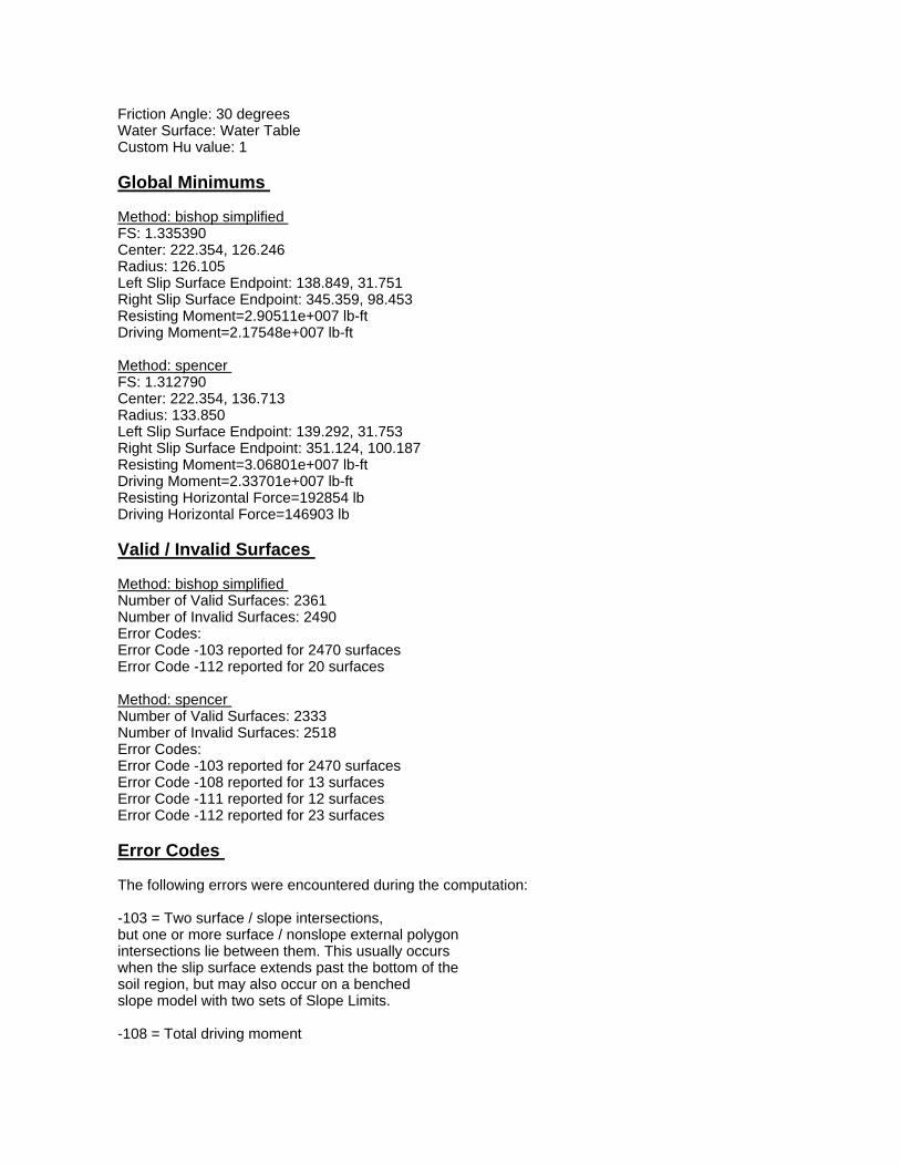
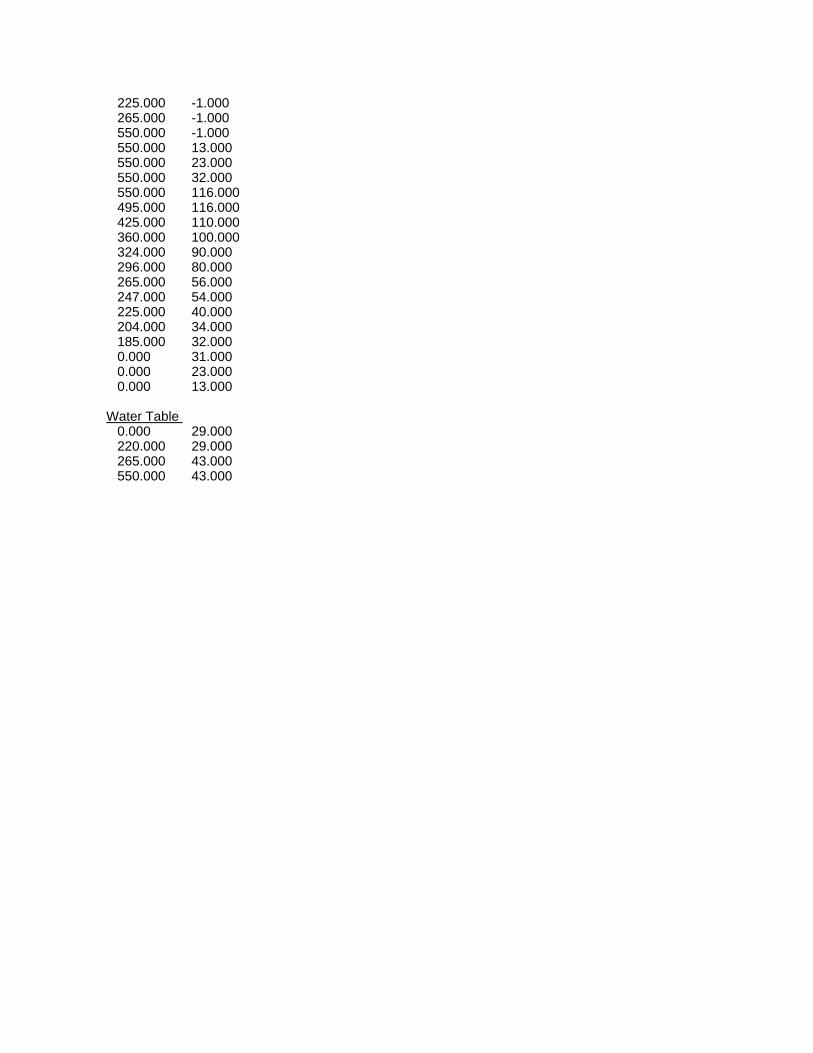
Friction Angle: 30 degrees Water Surface: Water Table Custom Hu value: 1 Global Minimums Method: bishop simplified FS: 1.335390 Center: 222.354, 126.246 Radius: 126.105 Left Slip Surface Endpoint: 138.849, 31.751 Right Slip Surface Endpoint: 345.359, 98.453 Resisting Moment=2.90511e+007 lb-ft Driving Moment=2.17548e+007 lb-ft Method: spencer FS: 1.312790 Center: 222.354, 136.713 Radius: 133.850 Left Slip Surface Endpoint: 139.292, 31.753 Right Slip Surface Endpoint: 351.124, 100.187 Resisting Moment=3.06801e+007 lb-ft Driving Moment=2.33701e+007 lb-ft Resisting Horizontal Force=192854 lb Driving Horizontal Force=146903 lb Valid / Invalid Surfaces Method: bishop simplified Number of Valid Surfaces: 2361 Number of Invalid Surfaces: 2490 Error Codes: Error Code -103 reported for 2470 surfaces Error Code -112 reported for 20 surfaces Method: spencer Number of Valid Surfaces: 2333 Number of Invalid Surfaces: 2518 Error Codes: Error Code -103 reported for 2470 surfaces Error Code -108 reported for 13 surfaces Error Code -111 reported for 12 surfaces Error Code -112 reported for 23 surfaces Error Codes The following errors were encountered during the computation: -103 = Two surface / slope intersections, but one or more surface / nonslope external polygon intersections lie between them. This usually occurs when the slip surface extends past the bottom of the soil region, but may also occur on a benched slope model with two sets of Slope Limits. -108 = Total driving moment

or total driving force < 0.1. This is to limit the calculation of extremely high safety factors if the driving force is very small (0.1 is an arbitrary number). -111 = safety factor equation did not converge -112 = The coefficient M-Alpha = cos(alpha)(1+tan(alpha)tan(phi)/F) < 0.2 for the final iteration of the safety factor calculation. This screens out some slip surfaces which may not be valid in the context of the analysis, in particular, deep seated slip surfaces with many high negative base angle slices in the passive zone. List of All Coordinates Search Grid 107.226 63.449 316.550 63.449 316.550 272.773 107.226 272.773 Material Boundary 185.000 32.000 204.000 34.000 225.000 40.000 240.000 50.000 245.000 54.000 265.000 56.000 270.000 60.000 283.000 70.000 296.000 80.000 324.000 90.000 360.000 100.000 425.000 110.000 495.000 116.000 550.000 116.000 Material Boundary 265.000 -1.000 265.000 13.000 265.000 23.000 265.000 32.000 265.000 56.000 Material Boundary 225.000 -1.000 225.000 13.000 225.000 23.000 225.000 32.000 225.000 40.000 Material Boundary 0.000 23.000 225.000 23.000 265.000 23.000
550.000 23.000 Material Boundary 0.000 13.000 225.000 13.000 265.000 13.000 550.000 13.000 Material Boundary 185.000 32.000 225.000 32.000 265.000 32.000 550.000 32.000 External Boundary 0.000 -1.000 225.000 -1.000 265.000 -1.000 550.000 -1.000 550.000 13.000 550.000 23.000 550.000 32.000 550.000 116.000 550.000 118.000 495.000 118.000 450.000 116.000 410.000 110.000 350.000 100.000 320.000 90.000 290.000 80.000 270.000 70.000 250.000 60.000 230.000 50.000 210.000 40.000 185.000 32.000 0.000 31.000 0.000 23.000 0.000 13.000 Water Table 0.000 29.000 220.000 29.000 265.000 43.000 550.000 43.000
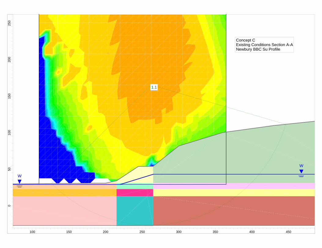
1.11.1
W
W
1.11.1
Concept CExisting Conditions Section A-ANewbury BBC Su Profile
250
200
150
100
500
100 150 200 250 300 350 400 450

Slide Analysis Information Document Name File Name: NBBC_AA_Existing.sli Project Settings Project Title: SLIDE - An Interactive Slope Stability Program Failure Direction: Right to Left Units of Measurement: Imperial Units Pore Fluid Unit Weight: 62.4 lb/ft3 Groundwater Method: Water Surfaces Data Output: Standard Calculate Excess Pore Pressure: Off Allow Ru with Water Surfaces or Grids: Off Random Numbers: Pseudo-random Seed Random Number Seed: 10116 Random Number Generation Method: Park and Miller v.3 Analysis Methods Analysis Methods used: Bishop simplified Spencer Number of slices: 25 Tolerance: 0.005 Maximum number of iterations: 50 Surface Options Surface Type: Circular Search Method: Grid Search Radius increment: 10 Composite Surfaces: Disabled Reverse Curvature: Create Tension Crack Minimum Elevation: Not Defined Minimum Depth: Not Defined Material Properties Material: Existing Berm Strength Type: Mohr-Coulomb Unit Weight: 118.5 lb/ft3 Cohesion: 0 psf Friction Angle: 40 degrees Water Surface: Water Table Custom Hu value: 1 Material: Landfill Waste Strength Type: Mohr-Coulomb Unit Weight: 70 lb/ft3 Cohesion: 200 psf Friction Angle: 25 degrees
Water Surface: Water Table Custom Hu value: 1 Material: Clay Zone 1A Strength Type: Undrained Unit Weight: 115 lb/ft3 Cohesion Type: Constant Cohesion: 485 psf Water Surface: None Material: Clay Zone 1B Strength Type: Undrained Unit Weight: 115 lb/ft3 Cohesion Type: Constant Cohesion: 587 psf Water Surface: None Material: Clay Zone 1C Strength Type: Undrained Unit Weight: 115 lb/ft3 Cohesion Type: Constant Cohesion: 687 psf Water Surface: None Material: Clay Zone 2A Strength Type: Undrained Unit Weight: 115 lb/ft3 Cohesion Type: Constant Cohesion: 902 psf Water Surface: None Material: Clay Zone 2B Strength Type: Undrained Unit Weight: 115 lb/ft3 Cohesion Type: Constant Cohesion: 910 psf Water Surface: None Material: Clay Zone 2C Strength Type: Undrained Unit Weight: 115 lb/ft3 Cohesion Type: Constant Cohesion: 861 psf Water Surface: None Material: Clay Zone 3A Strength Type: Undrained Unit Weight: 115 lb/ft3 Cohesion Type: Constant Cohesion: 1119 psf Water Surface: None Material: Clay Zone 3B Strength Type: Undrained Unit Weight: 115 lb/ft3 Cohesion Type: Constant Cohesion: 1086 psf

Water Surface: None Material: Clay Zone 3C Strength Type: Undrained Unit Weight: 115 lb/ft3 Cohesion Type: Constant Cohesion: 1220 psf Water Surface: None Global Minimums Method: bishop simplified FS: 1.129730 Center: 262.370, 165.347 Radius: 191.640 Left Slip Surface Endpoint: 126.333, 30.366 Right Slip Surface Endpoint: 446.329, 111.633 Resisting Moment=7.18029e+007 lb-ft Driving Moment=6.35578e+007 lb-ft Method: spencer FS: 1.114110 Center: 270.892, 190.912 Radius: 216.702 Left Slip Surface Endpoint: 125.353, 30.355 Right Slip Surface Endpoint: 473.623, 114.362 Resisting Moment=8.74241e+007 lb-ft Driving Moment=7.84697e+007 lb-ft Resisting Horizontal Force=342333 lb Driving Horizontal Force=307269 lb Valid / Invalid Surfaces Method: bishop simplified Number of Valid Surfaces: 6660 Number of Invalid Surfaces: 3911 Error Codes: Error Code -103 reported for 3618 surfaces Error Code -106 reported for 1 surface Error Code -107 reported for 3 surfaces Error Code -112 reported for 289 surfaces Method: spencer Number of Valid Surfaces: 6421 Number of Invalid Surfaces: 4150 Error Codes: Error Code -103 reported for 3618 surfaces Error Code -106 reported for 1 surface Error Code -107 reported for 3 surfaces Error Code -108 reported for 105 surfaces Error Code -111 reported for 100 surfaces Error Code -112 reported for 323 surfaces Error Codes The following errors were encountered during the computation:

-103 = Two surface / slope intersections, but one or more surface / nonslope external polygon intersections lie between them. This usually occurs when the slip surface extends past the bottom of the soil region, but may also occur on a benched slope model with two sets of Slope Limits. -106 = Average slice width is less than 0.0001 * (maximum horizontal extent of soil region). This limitation is imposed to avoid numerical errors which may result from too many slices, or too small a slip region. -107 = Total driving moment or total driving force is negative. This will occur if the wrong failure direction is specified, or if high external or anchor loads are applied against the failure direction. -108 = Total driving moment or total driving force < 0.1. This is to limit the calculation of extremely high safety factors if the driving force is very small (0.1 is an arbitrary number). -111 = safety factor equation did not converge -112 = The coefficient M-Alpha = cos(alpha)(1+tan(alpha)tan(phi)/F) < 0.2 for the final iteration of the safety factor calculation. This screens out some slip surfaces which may not be valid in the context of the analysis, in particular, deep seated slip surfaces with many high negative base angle slices in the passive zone. List of All Coordinates Search Grid 108.979 29.000 364.630 29.000 364.630 284.651 108.979 284.651 Material Boundary 0.000 13.000 215.000 13.000 257.000 13.000 265.000 13.000 550.000 13.000 Material Boundary 0.000 23.000 215.000 23.000 257.000 23.000 265.000 23.000 550.000 23.000
Material Boundary 200.000 31.000 215.000 31.000 257.000 31.000 265.000 31.000 550.000 31.000 Material Boundary 265.000 -27.000 265.000 13.000 265.000 23.000 265.000 31.000 265.000 50.889 265.000 54.000 Material Boundary 215.000 -27.000 215.000 13.000 215.000 23.000 215.000 31.000 215.000 34.000 External Boundary 0.000 -27.000 215.000 -27.000 265.000 -27.000 550.000 -27.000 550.000 13.000 550.000 23.000 550.000 31.000 550.000 116.000 490.000 116.000 430.000 110.000 360.000 100.000 300.000 82.000 265.000 54.000 245.000 54.000 215.000 34.000 200.000 31.000 185.000 31.000 0.000 29.000 0.000 23.000 0.000 13.000 Water Table 0.000 29.000 220.000 29.000 265.000 43.000 550.000 43.000
1.11.1
W
1.11.1
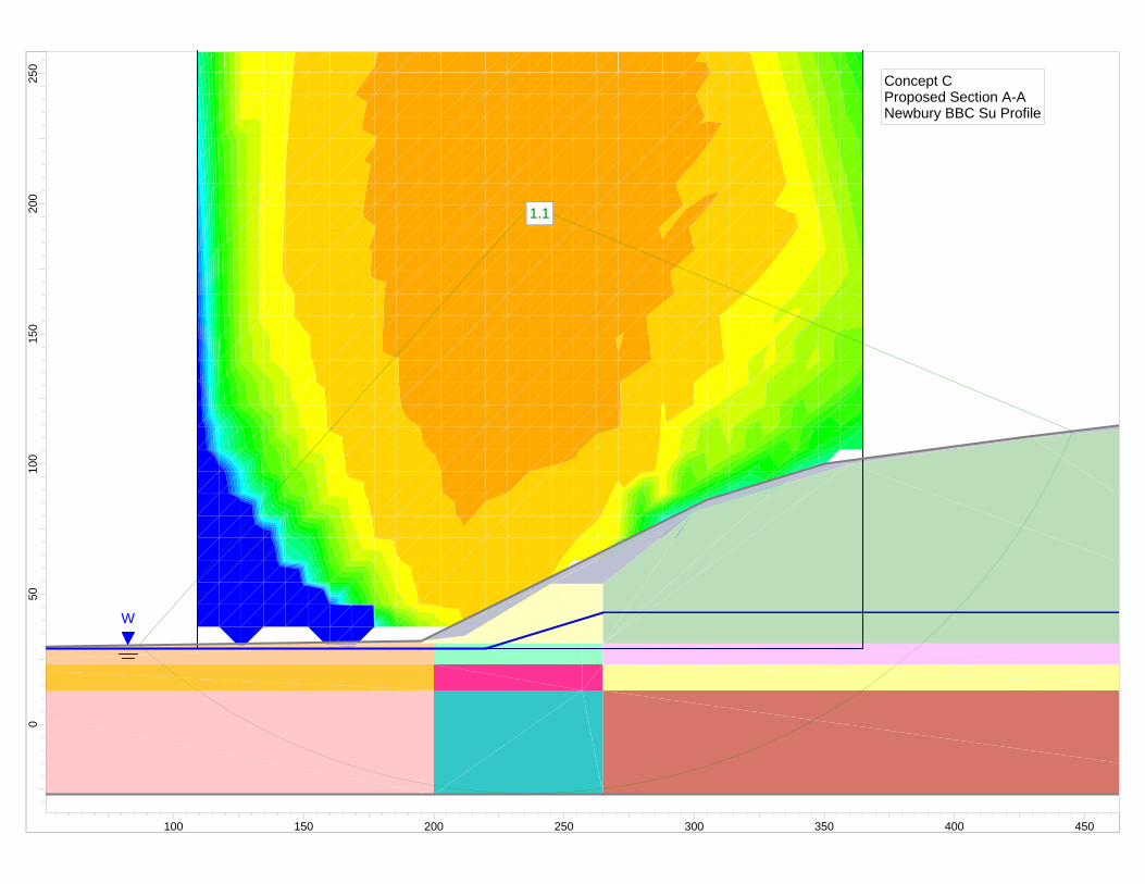
Concept CProposed Section A-ANewbury BBC Su Profile
250
200
150
100
500
100 150 200 250 300 350 400 450

Slide Analysis Information Document Name File Name: NBBC_AA_Proposed.sli Project Settings Project Title: SLIDE - An Interactive Slope Stability Program Failure Direction: Right to Left Units of Measurement: Imperial Units Pore Fluid Unit Weight: 62.4 lb/ft3 Groundwater Method: Water Surfaces Data Output: Standard Calculate Excess Pore Pressure: Off Allow Ru with Water Surfaces or Grids: Off Random Numbers: Pseudo-random Seed Random Number Seed: 10116 Random Number Generation Method: Park and Miller v.3 Analysis Methods Analysis Methods used: Bishop simplified Spencer Number of slices: 25 Tolerance: 0.005 Maximum number of iterations: 50 Surface Options Surface Type: Circular Search Method: Grid Search Radius increment: 10 Composite Surfaces: Disabled Reverse Curvature: Create Tension Crack Minimum Elevation: Not Defined Minimum Depth: Not Defined Material Properties Material: Existing Berm Strength Type: Mohr-Coulomb Unit Weight: 118.5 lb/ft3 Cohesion: 0 psf Friction Angle: 40 degrees Water Surface: Water Table Custom Hu value: 1 Material: Landfill Waste Strength Type: Mohr-Coulomb Unit Weight: 70 lb/ft3 Cohesion: 200 psf Friction Angle: 25 degrees

Water Surface: Water Table Custom Hu value: 1 Material: Clay Zone 1A Strength Type: Undrained Unit Weight: 115 lb/ft3 Cohesion Type: Constant Cohesion: 485 psf Water Surface: None Material: Clay Zone 1B Strength Type: Undrained Unit Weight: 115 lb/ft3 Cohesion Type: Constant Cohesion: 587 psf Water Surface: None Material: Clay Zone 1C Strength Type: Undrained Unit Weight: 115 lb/ft3 Cohesion Type: Constant Cohesion: 687 psf Water Surface: None Material: Clay Zone 2A Strength Type: Undrained Unit Weight: 115 lb/ft3 Cohesion Type: Constant Cohesion: 902 psf Water Surface: None Material: Clay Zone 2B Strength Type: Undrained Unit Weight: 115 lb/ft3 Cohesion Type: Constant Cohesion: 910 psf Water Surface: None Material: Clay Zone 2C Strength Type: Undrained Unit Weight: 115 lb/ft3 Cohesion Type: Constant Cohesion: 861 psf Water Surface: None Material: Clay Zone 3A Strength Type: Undrained Unit Weight: 115 lb/ft3 Cohesion Type: Constant Cohesion: 1119 psf Water Surface: None Material: Clay Zone 3B Strength Type: Undrained Unit Weight: 115 lb/ft3 Cohesion Type: Constant Cohesion: 1086 psf
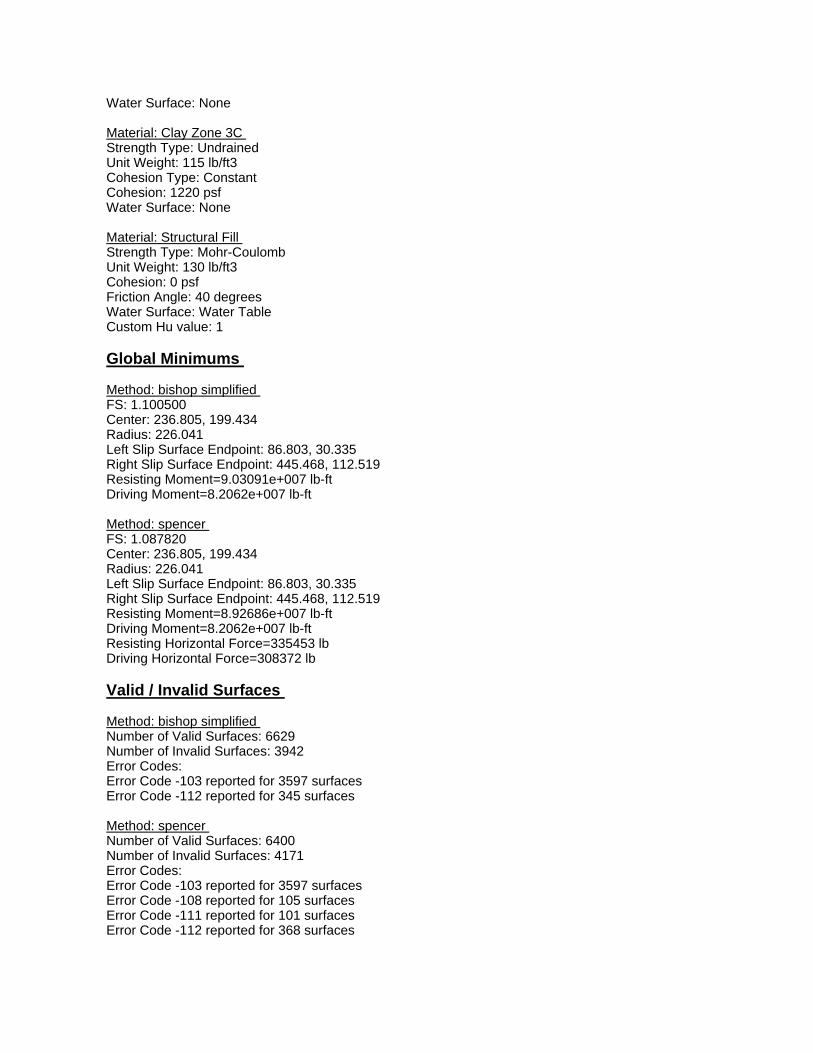
Water Surface: None Material: Clay Zone 3C Strength Type: Undrained Unit Weight: 115 lb/ft3 Cohesion Type: Constant Cohesion: 1220 psf Water Surface: None Material: Structural Fill Strength Type: Mohr-Coulomb Unit Weight: 130 lb/ft3 Cohesion: 0 psf Friction Angle: 40 degrees Water Surface: Water Table Custom Hu value: 1 Global Minimums Method: bishop simplified FS: 1.100500 Center: 236.805, 199.434 Radius: 226.041 Left Slip Surface Endpoint: 86.803, 30.335 Right Slip Surface Endpoint: 445.468, 112.519 Resisting Moment=9.03091e+007 lb-ft Driving Moment=8.2062e+007 lb-ft Method: spencer FS: 1.087820 Center: 236.805, 199.434 Radius: 226.041 Left Slip Surface Endpoint: 86.803, 30.335 Right Slip Surface Endpoint: 445.468, 112.519 Resisting Moment=8.92686e+007 lb-ft Driving Moment=8.2062e+007 lb-ft Resisting Horizontal Force=335453 lb Driving Horizontal Force=308372 lb Valid / Invalid Surfaces Method: bishop simplified Number of Valid Surfaces: 6629 Number of Invalid Surfaces: 3942 Error Codes: Error Code -103 reported for 3597 surfaces Error Code -112 reported for 345 surfaces Method: spencer Number of Valid Surfaces: 6400 Number of Invalid Surfaces: 4171 Error Codes: Error Code -103 reported for 3597 surfaces Error Code -108 reported for 105 surfaces Error Code -111 reported for 101 surfaces Error Code -112 reported for 368 surfaces

Error Codes The following errors were encountered during the computation: -103 = Two surface / slope intersections, but one or more surface / nonslope external polygon intersections lie between them. This usually occurs when the slip surface extends past the bottom of the soil region, but may also occur on a benched slope model with two sets of Slope Limits. -108 = Total driving moment or total driving force < 0.1. This is to limit the calculation of extremely high safety factors if the driving force is very small (0.1 is an arbitrary number). -111 = safety factor equation did not converge -112 = The coefficient M-Alpha = cos(alpha)(1+tan(alpha)tan(phi)/F) < 0.2 for the final iteration of the safety factor calculation. This screens out some slip surfaces which may not be valid in the context of the analysis, in particular, deep seated slip surfaces with many high negative base angle slices in the passive zone. List of All Coordinates Search Grid 108.979 29.000 364.630 29.000 364.630 284.651 108.979 284.651 Material Boundary 0.000 13.000 200.000 13.000 257.000 13.000 265.000 13.000 550.000 13.000 Material Boundary 0.000 23.000 200.000 23.000 257.000 23.000 265.000 23.000 550.000 23.000 Material Boundary 200.000 23.000 200.000 31.000 Material Boundary 200.000 -27.000 200.000 13.000

200.000 23.000 Material Boundary 200.000 31.000 257.000 31.000 265.000 31.000 550.000 31.000 Material Boundary 265.000 54.000 300.000 82.000 332.759 91.828 360.000 100.000 430.000 110.000 490.000 116.000 550.000 116.000 Material Boundary 265.000 -27.000 265.000 13.000 265.000 23.000 265.000 31.000 265.000 54.000 Material Boundary 195.000 32.000 195.000 31.000 200.000 31.000 Material Boundary 195.000 32.000 212.000 34.000 245.000 54.000 265.000 54.000 External Boundary 0.000 -27.000 200.000 -27.000 265.000 -27.000 550.000 -27.000 550.000 13.000 550.000 23.000 550.000 31.000 550.000 116.000 550.000 118.000 490.000 118.000 425.000 110.000 350.000 100.000 305.000 86.500 195.000 32.000 0.000 29.000 0.000 23.000 0.000 13.000 Water Table 0.000 29.000

220.000 29.000 265.000 43.000 550.000 43.000
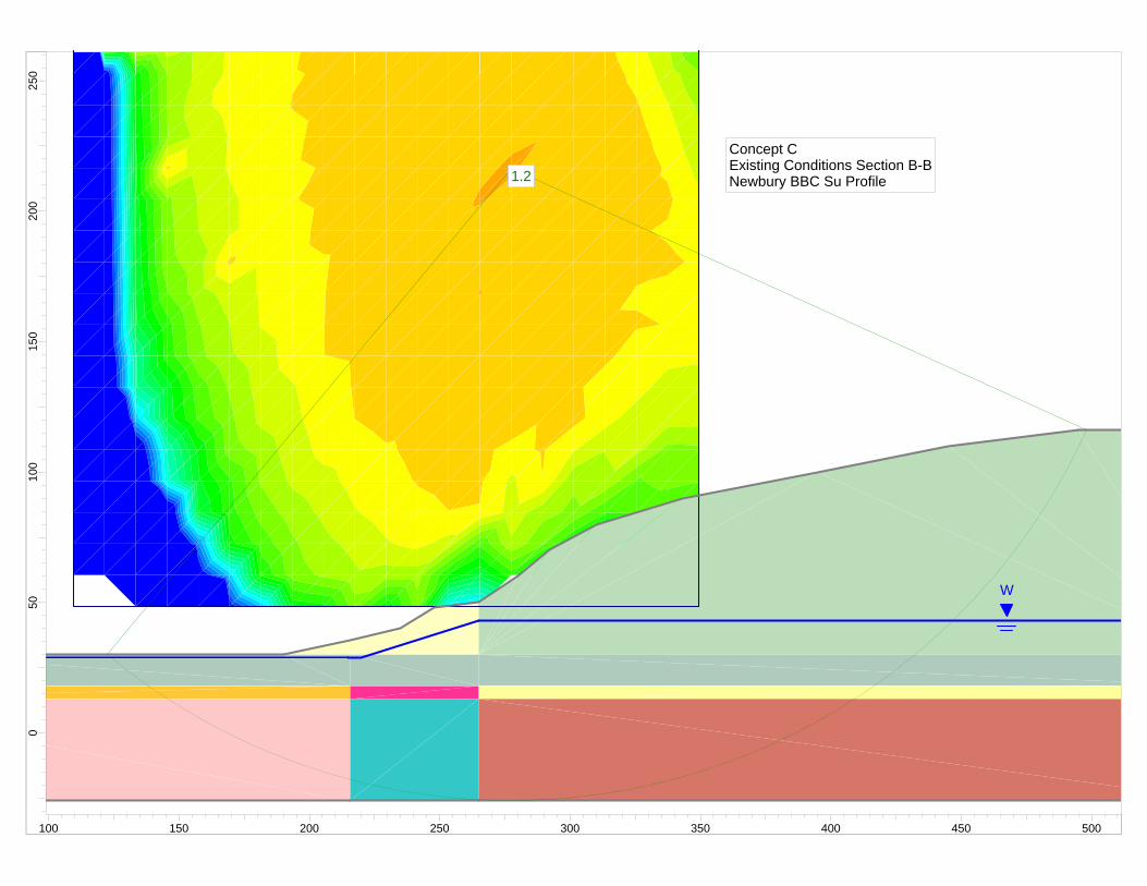
1.21.2
W
1.21.2
Concept CExisting Conditions Section B-BNewbury BBC Su Profile
250
200
150
100
500
100 150 200 250 300 350 400 450 500

Slide Analysis Information Document Name File Name: NBBC_BB_Existing.sli Project Settings Project Title: SLIDE - An Interactive Slope Stability Program Failure Direction: Right to Left Units of Measurement: Imperial Units Pore Fluid Unit Weight: 62.4 lb/ft3 Groundwater Method: Water Surfaces Data Output: Standard Calculate Excess Pore Pressure: Off Allow Ru with Water Surfaces or Grids: Off Random Numbers: Pseudo-random Seed Random Number Seed: 10116 Random Number Generation Method: Park and Miller v.3 Analysis Methods Analysis Methods used: Bishop simplified Spencer Number of slices: 25 Tolerance: 0.005 Maximum number of iterations: 50 Surface Options Surface Type: Circular Search Method: Grid Search Radius increment: 10 Composite Surfaces: Disabled Reverse Curvature: Create Tension Crack Minimum Elevation: Not Defined Minimum Depth: Not Defined Material Properties Material: Existing Berm Strength Type: Mohr-Coulomb Unit Weight: 118.5 lb/ft3 Cohesion: 0 psf Friction Angle: 40 degrees Water Surface: Water Table Custom Hu value: 1 Material: Landfill Waste Strength Type: Mohr-Coulomb Unit Weight: 70 lb/ft3 Cohesion: 200 psf Friction Angle: 25 degrees
Water Surface: Water Table Custom Hu value: 1 Material: Clay Zone 1B Strength Type: Undrained Unit Weight: 115 lb/ft3 Cohesion Type: Constant Cohesion: 587 psf Water Surface: None Material: Clay Zone 1C Strength Type: Undrained Unit Weight: 115 lb/ft3 Cohesion Type: Constant Cohesion: 687 psf Water Surface: None Material: Clay Zone 2B Strength Type: Undrained Unit Weight: 115 lb/ft3 Cohesion Type: Constant Cohesion: 910 psf Water Surface: None Material: Clay Zone 2C Strength Type: Undrained Unit Weight: 115 lb/ft3 Cohesion Type: Constant Cohesion: 861 psf Water Surface: None Material: Clay Zone 3B Strength Type: Undrained Unit Weight: 115 lb/ft3 Cohesion Type: Constant Cohesion: 1086 psf Water Surface: None Material: Clay Zone 3C Strength Type: Undrained Unit Weight: 115 lb/ft3 Cohesion Type: Constant Cohesion: 1220 psf Water Surface: None Material: Fill Strength Type: Mohr-Coulomb Unit Weight: 118.5 lb/ft3 Cohesion: 0 psf Friction Angle: 30 degrees Water Surface: Water Table Custom Hu value: 1 Global Minimums Method: bishop simplified FS: 1.234000
Center: 277.414, 216.531 Radius: 242.400 Left Slip Surface Endpoint: 122.612, 30.000 Right Slip Surface Endpoint: 497.983, 116.000 Resisting Moment=1.11309e+008 lb-ft Driving Moment=9.02021e+007 lb-ft Method: spencer FS: 1.220640 Center: 277.414, 216.531 Radius: 242.400 Left Slip Surface Endpoint: 122.612, 30.000 Right Slip Surface Endpoint: 497.983, 116.000 Resisting Moment=1.10104e+008 lb-ft Driving Moment=9.02021e+007 lb-ft Resisting Horizontal Force=389126 lb Driving Horizontal Force=318789 lb Valid / Invalid Surfaces Method: bishop simplified Number of Valid Surfaces: 2896 Number of Invalid Surfaces: 1955 Error Codes: Error Code -103 reported for 1559 surfaces Error Code -107 reported for 67 surfaces Error Code -108 reported for 250 surfaces Error Code -112 reported for 79 surfaces Method: spencer Number of Valid Surfaces: 2801 Number of Invalid Surfaces: 2050 Error Codes: Error Code -103 reported for 1559 surfaces Error Code -107 reported for 67 surfaces Error Code -108 reported for 301 surfaces Error Code -111 reported for 20 surfaces Error Code -112 reported for 103 surfaces Error Codes The following errors were encountered during the computation: -103 = Two surface / slope intersections, but one or more surface / nonslope external polygon intersections lie between them. This usually occurs when the slip surface extends past the bottom of the soil region, but may also occur on a benched slope model with two sets of Slope Limits. -107 = Total driving moment or total driving force is negative. This will occur if the wrong failure direction is specified, or if high external or anchor loads are applied against the failure direction.
-108 = Total driving moment or total driving force < 0.1. This is to limit the calculation of extremely high safety factors if the driving force is very small (0.1 is an arbitrary number). -111 = safety factor equation did not converge -112 = The coefficient M-Alpha = cos(alpha)(1+tan(alpha)tan(phi)/F) < 0.2 for the final iteration of the safety factor calculation. This screens out some slip surfaces which may not be valid in the context of the analysis, in particular, deep seated slip surfaces with many high negative base angle slices in the passive zone. List of All Coordinates Search Grid 109.391 48.509 349.423 48.509 349.423 288.541 109.391 288.541 Material Boundary 0.000 18.000 215.664 18.000 265.000 18.000 550.000 18.000 Material Boundary 0.000 13.000 215.664 13.000 265.000 13.000 550.000 13.000 Material Boundary 265.000 -26.000 265.000 13.000 265.000 18.000 265.000 30.000 265.000 50.000 Material Boundary 215.664 -26.000 215.664 13.000 215.664 18.000 215.664 30.000 215.664 35.703 Material Boundary 190.000 30.000 215.664 30.000 265.000 30.000 550.000 30.000 External Boundary

0.000 -26.000 215.664 -26.000 265.000 -26.000 550.000 -26.000 550.000 13.000 550.000 18.000 550.000 30.000 550.000 116.000 495.000 116.000 445.000 110.000 395.000 100.000 343.000 90.000 310.000 80.000 292.000 70.000 280.000 60.000 265.000 50.000 248.000 48.000 235.000 40.000 215.664 35.703 190.000 30.000 45.000 30.000 0.000 31.000 0.000 18.000 0.000 13.000 Water Table 0.000 29.000 215.000 29.000 220.000 29.000 265.000 43.000 550.000 43.000
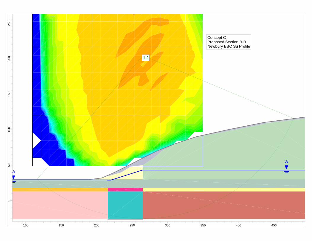
1.21.2
W
W
1.21.2
Concept CProposed Section B-BNewbury BBC Su Profile
250
200
150
100
500
100 150 200 250 300 350 400 450

Slide Analysis Information Document Name File Name: NBBC_BB_Proposed.sli Project Settings Project Title: SLIDE - An Interactive Slope Stability Program Failure Direction: Right to Left Units of Measurement: Imperial Units Pore Fluid Unit Weight: 62.4 lb/ft3 Groundwater Method: Water Surfaces Data Output: Standard Calculate Excess Pore Pressure: Off Allow Ru with Water Surfaces or Grids: Off Random Numbers: Pseudo-random Seed Random Number Seed: 10116 Random Number Generation Method: Park and Miller v.3 Analysis Methods Analysis Methods used: Bishop simplified Spencer Number of slices: 25 Tolerance: 0.005 Maximum number of iterations: 50 Surface Options Surface Type: Circular Search Method: Grid Search Radius increment: 10 Composite Surfaces: Disabled Reverse Curvature: Create Tension Crack Minimum Elevation: Not Defined Minimum Depth: Not Defined Material Properties Material: Existing Berm Strength Type: Mohr-Coulomb Unit Weight: 118.5 lb/ft3 Cohesion: 0 psf Friction Angle: 40 degrees Water Surface: Water Table Custom Hu value: 1 Material: Landfill Waste Strength Type: Mohr-Coulomb Unit Weight: 70 lb/ft3 Cohesion: 200 psf Friction Angle: 25 degrees

Water Surface: Water Table Custom Hu value: 1 Material: Clay Zone 1B Strength Type: Undrained Unit Weight: 115 lb/ft3 Cohesion Type: Constant Cohesion: 587 psf Water Surface: None Material: Clay Zone 1C Strength Type: Undrained Unit Weight: 115 lb/ft3 Cohesion Type: Constant Cohesion: 687 psf Water Surface: None Material: Clay Zone 2B Strength Type: Undrained Unit Weight: 115 lb/ft3 Cohesion Type: Constant Cohesion: 910 psf Water Surface: None Material: Clay Zone 2C Strength Type: Undrained Unit Weight: 115 lb/ft3 Cohesion Type: Constant Cohesion: 861 psf Water Surface: None Material: Clay Zone 3B Strength Type: Undrained Unit Weight: 115 lb/ft3 Cohesion Type: Constant Cohesion: 1086 psf Water Surface: None Material: Clay Zone 3C Strength Type: Undrained Unit Weight: 115 lb/ft3 Cohesion Type: Constant Cohesion: 1220 psf Water Surface: None Material: Structural Fill Strength Type: Mohr-Coulomb Unit Weight: 130 lb/ft3 Cohesion: 0 psf Friction Angle: 40 degrees Water Surface: Water Table Custom Hu value: 1 Material: Fill Strength Type: Mohr-Coulomb Unit Weight: 118.5 lb/ft3 Cohesion: 0 psf

Friction Angle: 30 degrees Water Surface: Water Table Custom Hu value: 1 Global Minimums Method: bishop simplified FS: 1.195870 Center: 265.412, 204.530 Radius: 230.075 Left Slip Surface Endpoint: 115.499, 30.000 Right Slip Surface Endpoint: 477.641, 115.685 Resisting Moment=1.01125e+008 lb-ft Driving Moment=8.45621e+007 lb-ft Method: spencer FS: 1.180990 Center: 265.412, 204.530 Radius: 230.075 Left Slip Surface Endpoint: 115.499, 30.000 Right Slip Surface Endpoint: 477.641, 115.685 Resisting Moment=9.9867e+007 lb-ft Driving Moment=8.45621e+007 lb-ft Resisting Horizontal Force=368840 lb Driving Horizontal Force=312314 lb Valid / Invalid Surfaces Method: bishop simplified Number of Valid Surfaces: 2879 Number of Invalid Surfaces: 1972 Error Codes: Error Code -103 reported for 1541 surfaces Error Code -107 reported for 82 surfaces Error Code -108 reported for 247 surfaces Error Code -112 reported for 102 surfaces Method: spencer Number of Valid Surfaces: 2767 Number of Invalid Surfaces: 2084 Error Codes: Error Code -103 reported for 1541 surfaces Error Code -107 reported for 82 surfaces Error Code -108 reported for 311 surfaces Error Code -111 reported for 23 surfaces Error Code -112 reported for 127 surfaces Error Codes The following errors were encountered during the computation: -103 = Two surface / slope intersections, but one or more surface / nonslope external polygon intersections lie between them. This usually occurs when the slip surface extends past the bottom of the soil region, but may also occur on a benched

slope model with two sets of Slope Limits. -107 = Total driving moment or total driving force is negative. This will occur if the wrong failure direction is specified, or if high external or anchor loads are applied against the failure direction. -108 = Total driving moment or total driving force < 0.1. This is to limit the calculation of extremely high safety factors if the driving force is very small (0.1 is an arbitrary number). -111 = safety factor equation did not converge -112 = The coefficient M-Alpha = cos(alpha)(1+tan(alpha)tan(phi)/F) < 0.2 for the final iteration of the safety factor calculation. This screens out some slip surfaces which may not be valid in the context of the analysis, in particular, deep seated slip surfaces with many high negative base angle slices in the passive zone. List of All Coordinates Search Grid 109.391 48.509 349.423 48.509 349.423 288.541 109.391 288.541 Material Boundary 0.000 18.000 215.664 18.000 265.000 18.000 550.000 18.000 Material Boundary 0.000 13.000 215.664 13.000 265.000 13.000 550.000 13.000 Material Boundary 265.000 -26.000 265.000 13.000 265.000 18.000 265.000 30.000 265.000 50.000 265.000 60.000 Material Boundary 190.000 30.000 215.664 30.000 265.000 30.000 550.000 30.000

Material Boundary 207.000 32.000 215.664 34.475 235.000 40.000 248.000 48.000 265.000 50.000 280.000 60.000 292.000 70.000 310.000 80.000 343.000 90.000 395.000 100.000 445.000 110.000 495.000 116.000 550.000 116.000 Material Boundary 215.664 -26.000 215.664 13.000 215.664 18.000 215.664 30.000 215.664 34.475 External Boundary 0.000 -26.000 215.664 -26.000 265.000 -26.000 550.000 -26.000 550.000 13.000 550.000 18.000 550.000 30.000 550.000 116.000 550.000 118.000 495.000 118.000 435.000 110.000 385.000 100.000 340.000 90.000 310.000 80.000 285.000 70.000 265.000 60.000 245.000 50.000 225.000 40.000 207.000 32.000 190.000 30.000 45.000 30.000 0.000 31.000 0.000 18.000 0.000 13.000 Water Table 0.000 29.000 215.000 29.000 220.000 29.000 265.000 43.000 550.000 43.000
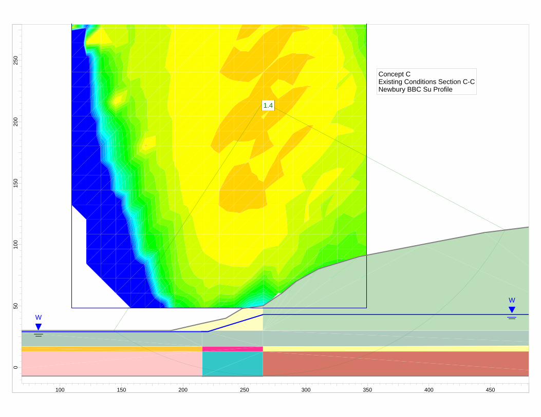
1.41.4
W
W
1.41.4
Concept CExisting Conditions Section C-CNewbury BBC Su Profile
250
200
150
100
500
100 150 200 250 300 350 400 450

Slide Analysis Information Document Name File Name: NBBC_CC_Existing.sli Project Settings Project Title: SLIDE - An Interactive Slope Stability Program Failure Direction: Right to Left Units of Measurement: Imperial Units Pore Fluid Unit Weight: 62.4 lb/ft3 Groundwater Method: Water Surfaces Data Output: Standard Calculate Excess Pore Pressure: Off Allow Ru with Water Surfaces or Grids: Off Random Numbers: Pseudo-random Seed Random Number Seed: 10116 Random Number Generation Method: Park and Miller v.3 Analysis Methods Analysis Methods used: Bishop simplified Spencer Number of slices: 25 Tolerance: 0.005 Maximum number of iterations: 50 Surface Options Surface Type: Circular Search Method: Grid Search Radius increment: 10 Composite Surfaces: Disabled Reverse Curvature: Create Tension Crack Minimum Elevation: Not Defined Minimum Depth: Not Defined Material Properties Material: Existing Berm Strength Type: Mohr-Coulomb Unit Weight: 118.5 lb/ft3 Cohesion: 0 psf Friction Angle: 40 degrees Water Surface: Water Table Custom Hu value: 1 Material: Landfill Waste Strength Type: Mohr-Coulomb Unit Weight: 70 lb/ft3 Cohesion: 200 psf Friction Angle: 25 degrees

Water Surface: Water Table Custom Hu value: 1 Material: Clay Zone 1B Strength Type: Undrained Unit Weight: 115 lb/ft3 Cohesion Type: Constant Cohesion: 587 psf Water Surface: None Material: Clay Zone 1C Strength Type: Undrained Unit Weight: 115 lb/ft3 Cohesion Type: Constant Cohesion: 687 psf Water Surface: None Material: Clay Zone 2B Strength Type: Undrained Unit Weight: 115 lb/ft3 Cohesion Type: Constant Cohesion: 910 psf Water Surface: None Material: Clay Zone 2C Strength Type: Undrained Unit Weight: 115 lb/ft3 Cohesion Type: Constant Cohesion: 861 psf Water Surface: None Material: Clay Zone 3B Strength Type: Undrained Unit Weight: 115 lb/ft3 Cohesion Type: Constant Cohesion: 1086 psf Water Surface: None Material: Clay Zone 3C Strength Type: Undrained Unit Weight: 115 lb/ft3 Cohesion Type: Constant Cohesion: 1220 psf Water Surface: None Material: Fill Strength Type: Mohr-Coulomb Unit Weight: 118.5 lb/ft3 Cohesion: 0 psf Friction Angle: 30 degrees Water Surface: Water Table Custom Hu value: 1 Global Minimums Method: bishop simplified FS: 1.397250

Center: 265.412, 216.531 Radius: 222.725 Left Slip Surface Endpoint: 143.705, 30.000 Right Slip Surface Endpoint: 462.112, 112.053 Resisting Moment=8.51469e+007 lb-ft Driving Moment=6.09391e+007 lb-ft Method: spencer FS: 1.372300 Center: 265.412, 216.531 Radius: 222.725 Left Slip Surface Endpoint: 143.705, 30.000 Right Slip Surface Endpoint: 462.112, 112.053 Resisting Moment=8.36267e+007 lb-ft Driving Moment=6.09391e+007 lb-ft Resisting Horizontal Force=329635 lb Driving Horizontal Force=240207 lb Valid / Invalid Surfaces Method: bishop simplified Number of Valid Surfaces: 2278 Number of Invalid Surfaces: 2573 Error Codes: Error Code -103 reported for 2231 surfaces Error Code -107 reported for 56 surfaces Error Code -108 reported for 251 surfaces Error Code -112 reported for 35 surfaces Method: spencer Number of Valid Surfaces: 2223 Number of Invalid Surfaces: 2628 Error Codes: Error Code -103 reported for 2231 surfaces Error Code -107 reported for 56 surfaces Error Code -108 reported for 287 surfaces Error Code -111 reported for 14 surfaces Error Code -112 reported for 40 surfaces Error Codes The following errors were encountered during the computation: -103 = Two surface / slope intersections, but one or more surface / nonslope external polygon intersections lie between them. This usually occurs when the slip surface extends past the bottom of the soil region, but may also occur on a benched slope model with two sets of Slope Limits. -107 = Total driving moment or total driving force is negative. This will occur if the wrong failure direction is specified, or if high external or anchor loads are applied against the failure direction.

-108 = Total driving moment or total driving force < 0.1. This is to limit the calculation of extremely high safety factors if the driving force is very small (0.1 is an arbitrary number). -111 = safety factor equation did not converge -112 = The coefficient M-Alpha = cos(alpha)(1+tan(alpha)tan(phi)/F) < 0.2 for the final iteration of the safety factor calculation. This screens out some slip surfaces which may not be valid in the context of the analysis, in particular, deep seated slip surfaces with many high negative base angle slices in the passive zone. List of All Coordinates Search Grid 109.391 48.509 349.423 48.509 349.423 288.541 109.391 288.541 Material Boundary 265.000 17.000 550.000 18.000 Material Boundary 0.000 13.000 215.664 13.000 265.000 13.000 550.000 13.000 Material Boundary 265.000 -7.000 265.000 13.000 265.000 17.000 265.000 30.000 265.000 50.000 Material Boundary 215.664 -7.000 215.664 13.000 215.664 17.000 215.664 30.000 215.664 35.703 Material Boundary 190.000 30.000 215.664 30.000 265.000 30.000 550.000 30.000 Material Boundary 0.000 17.000 215.664 17.000
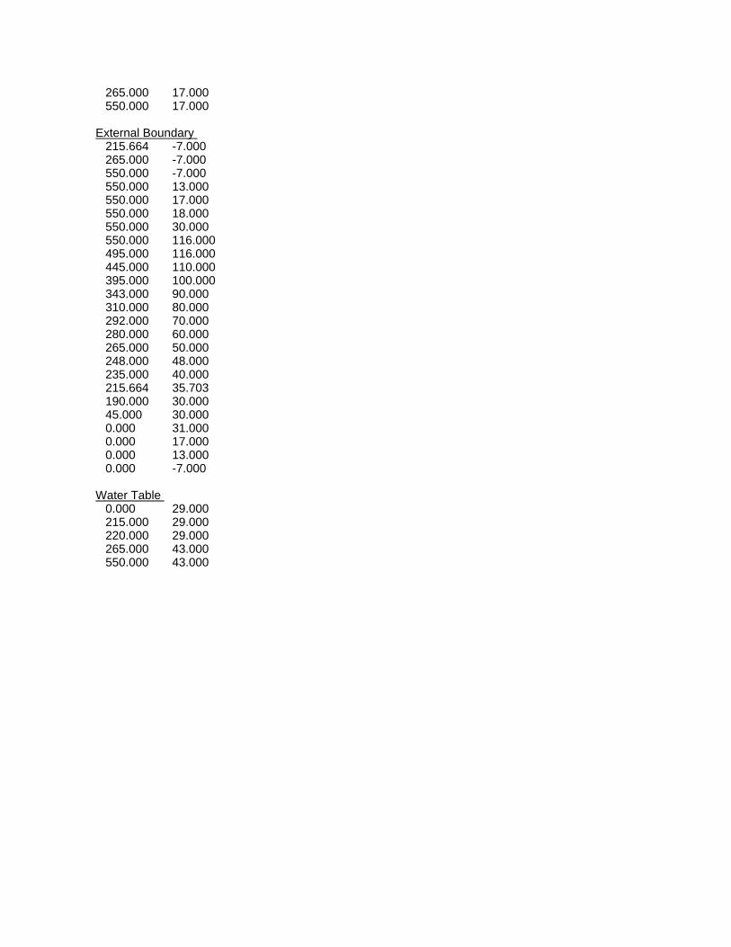
265.000 17.000 550.000 17.000 External Boundary 215.664 -7.000 265.000 -7.000 550.000 -7.000 550.000 13.000 550.000 17.000 550.000 18.000 550.000 30.000 550.000 116.000 495.000 116.000 445.000 110.000 395.000 100.000 343.000 90.000 310.000 80.000 292.000 70.000 280.000 60.000 265.000 50.000 248.000 48.000 235.000 40.000 215.664 35.703 190.000 30.000 45.000 30.000 0.000 31.000 0.000 17.000 0.000 13.000 0.000 -7.000 Water Table 0.000 29.000 215.000 29.000 220.000 29.000 265.000 43.000 550.000 43.000

1.31.3
W
W
1.31.3
Concept CProposed Section C-CNewbury BBC Su Profile
250
200
150
100
500
100 150 200 250 300 350 400 450

Slide Analysis Information Document Name File Name: NBBC_CC_Proposed.sli Project Settings Project Title: SLIDE - An Interactive Slope Stability Program Failure Direction: Right to Left Units of Measurement: Imperial Units Pore Fluid Unit Weight: 62.4 lb/ft3 Groundwater Method: Water Surfaces Data Output: Standard Calculate Excess Pore Pressure: Off Allow Ru with Water Surfaces or Grids: Off Random Numbers: Pseudo-random Seed Random Number Seed: 10116 Random Number Generation Method: Park and Miller v.3 Analysis Methods Analysis Methods used: Bishop simplified Spencer Number of slices: 25 Tolerance: 0.005 Maximum number of iterations: 50 Surface Options Surface Type: Circular Search Method: Grid Search Radius increment: 10 Composite Surfaces: Disabled Reverse Curvature: Create Tension Crack Minimum Elevation: Not Defined Minimum Depth: Not Defined Material Properties Material: Existing Berm Strength Type: Mohr-Coulomb Unit Weight: 118.5 lb/ft3 Cohesion: 0 psf Friction Angle: 40 degrees Water Surface: Water Table Custom Hu value: 1 Material: Landfill Waste Strength Type: Mohr-Coulomb Unit Weight: 70 lb/ft3 Cohesion: 200 psf Friction Angle: 25 degrees
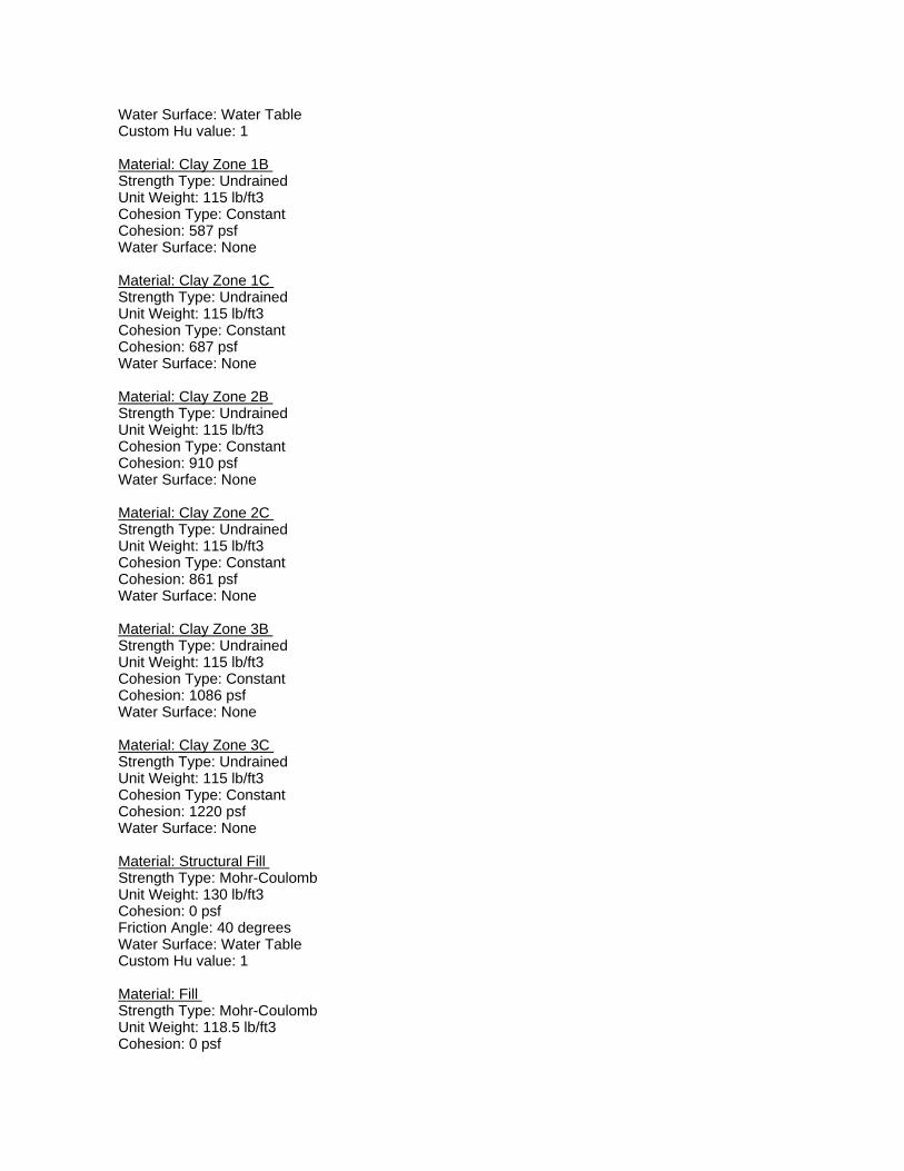
Water Surface: Water Table Custom Hu value: 1 Material: Clay Zone 1B Strength Type: Undrained Unit Weight: 115 lb/ft3 Cohesion Type: Constant Cohesion: 587 psf Water Surface: None Material: Clay Zone 1C Strength Type: Undrained Unit Weight: 115 lb/ft3 Cohesion Type: Constant Cohesion: 687 psf Water Surface: None Material: Clay Zone 2B Strength Type: Undrained Unit Weight: 115 lb/ft3 Cohesion Type: Constant Cohesion: 910 psf Water Surface: None Material: Clay Zone 2C Strength Type: Undrained Unit Weight: 115 lb/ft3 Cohesion Type: Constant Cohesion: 861 psf Water Surface: None Material: Clay Zone 3B Strength Type: Undrained Unit Weight: 115 lb/ft3 Cohesion Type: Constant Cohesion: 1086 psf Water Surface: None Material: Clay Zone 3C Strength Type: Undrained Unit Weight: 115 lb/ft3 Cohesion Type: Constant Cohesion: 1220 psf Water Surface: None Material: Structural Fill Strength Type: Mohr-Coulomb Unit Weight: 130 lb/ft3 Cohesion: 0 psf Friction Angle: 40 degrees Water Surface: Water Table Custom Hu value: 1 Material: Fill Strength Type: Mohr-Coulomb Unit Weight: 118.5 lb/ft3 Cohesion: 0 psf

Friction Angle: 30 degrees Water Surface: Water Table Custom Hu value: 1 Global Minimums Method: bishop simplified FS: 1.338750 Center: 241.409, 180.527 Radius: 186.524 Left Slip Surface Endpoint: 131.259, 30.000 Right Slip Surface Endpoint: 412.147, 105.429 Resisting Moment=5.9034e+007 lb-ft Driving Moment=4.40964e+007 lb-ft Method: spencer FS: 1.319920 Center: 241.409, 180.527 Radius: 186.524 Left Slip Surface Endpoint: 131.259, 30.000 Right Slip Surface Endpoint: 412.147, 105.429 Resisting Moment=5.82036e+007 lb-ft Driving Moment=4.40964e+007 lb-ft Resisting Horizontal Force=267915 lb Driving Horizontal Force=202978 lb Valid / Invalid Surfaces Method: bishop simplified Number of Valid Surfaces: 2265 Number of Invalid Surfaces: 2586 Error Codes: Error Code -103 reported for 2214 surfaces Error Code -107 reported for 70 surfaces Error Code -108 reported for 248 surfaces Error Code -112 reported for 54 surfaces Method: spencer Number of Valid Surfaces: 2201 Number of Invalid Surfaces: 2650 Error Codes: Error Code -103 reported for 2214 surfaces Error Code -107 reported for 70 surfaces Error Code -108 reported for 292 surfaces Error Code -111 reported for 12 surfaces Error Code -112 reported for 62 surfaces Error Codes The following errors were encountered during the computation: -103 = Two surface / slope intersections, but one or more surface / nonslope external polygon intersections lie between them. This usually occurs when the slip surface extends past the bottom of the soil region, but may also occur on a benched
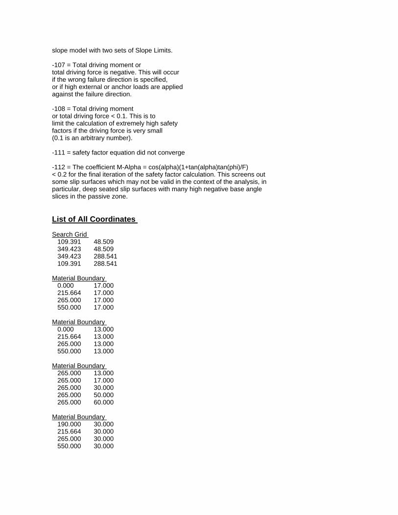
slope model with two sets of Slope Limits. -107 = Total driving moment or total driving force is negative. This will occur if the wrong failure direction is specified, or if high external or anchor loads are applied against the failure direction. -108 = Total driving moment or total driving force < 0.1. This is to limit the calculation of extremely high safety factors if the driving force is very small (0.1 is an arbitrary number). -111 = safety factor equation did not converge -112 = The coefficient M-Alpha = cos(alpha)(1+tan(alpha)tan(phi)/F) < 0.2 for the final iteration of the safety factor calculation. This screens out some slip surfaces which may not be valid in the context of the analysis, in particular, deep seated slip surfaces with many high negative base angle slices in the passive zone. List of All Coordinates Search Grid 109.391 48.509 349.423 48.509 349.423 288.541 109.391 288.541 Material Boundary 0.000 17.000 215.664 17.000 265.000 17.000 550.000 17.000 Material Boundary 0.000 13.000 215.664 13.000 265.000 13.000 550.000 13.000 Material Boundary 265.000 13.000 265.000 17.000 265.000 30.000 265.000 50.000 265.000 60.000 Material Boundary 190.000 30.000 215.664 30.000 265.000 30.000 550.000 30.000

Material Boundary 207.000 32.000 215.664 34.475 235.000 40.000 248.000 48.000 265.000 50.000 280.000 60.000 292.000 70.000 310.000 80.000 343.000 90.000 395.000 100.000 445.000 110.000 495.000 116.000 550.000 116.000 Material Boundary 215.664 13.000 215.664 17.000 215.664 30.000 215.664 34.475 Material Boundary 215.664 -7.000 215.664 13.000 Material Boundary 265.000 -7.000 265.000 13.000 External Boundary 0.000 -7.000 215.664 -7.000 265.000 -7.000 550.000 -7.000 550.000 13.000 550.000 17.000 550.000 30.000 550.000 116.000 550.000 118.000 495.000 118.000 435.000 110.000 385.000 100.000 340.000 90.000 310.000 80.000 285.000 70.000 265.000 60.000 245.000 50.000 225.000 40.000 207.000 32.000 190.000 30.000 45.000 30.000 0.000 31.000 0.000 17.000 0.000 13.000 Water Table

0.000 29.000 215.000 29.000 220.000 29.000 265.000 43.000 550.000 43.000

1.31.3
W
W
1.31.3
Concept CExisting Conditions Section D-DNewbury BBC Su Profile
250
200
150
100
500
100 150 200 250 300 350 400 450

Slide Analysis Information Document Name File Name: NBBC_DD_Existing.sli Project Settings Project Title: SLIDE - An Interactive Slope Stability Program Failure Direction: Right to Left Units of Measurement: Imperial Units Pore Fluid Unit Weight: 62.4 lb/ft3 Groundwater Method: Water Surfaces Data Output: Standard Calculate Excess Pore Pressure: Off Allow Ru with Water Surfaces or Grids: Off Random Numbers: Pseudo-random Seed Random Number Seed: 10116 Random Number Generation Method: Park and Miller v.3 Analysis Methods Analysis Methods used: Bishop simplified Spencer Number of slices: 25 Tolerance: 0.005 Maximum number of iterations: 50 Surface Options Surface Type: Circular Search Method: Grid Search Radius increment: 10 Composite Surfaces: Disabled Reverse Curvature: Create Tension Crack Minimum Elevation: Not Defined Minimum Depth: Not Defined Material Properties Material: Existing Berm Strength Type: Mohr-Coulomb Unit Weight: 118.5 lb/ft3 Cohesion: 0 psf Friction Angle: 40 degrees Water Surface: Water Table Custom Hu value: 1 Material: Landfill Waste Strength Type: Mohr-Coulomb Unit Weight: 70 lb/ft3 Cohesion: 200 psf Friction Angle: 25 degrees

Water Surface: Water Table Custom Hu value: 1 Material: Clay Zone 1B Strength Type: Undrained Unit Weight: 115 lb/ft3 Cohesion Type: Constant Cohesion: 587 psf Water Surface: None Material: Clay Zone 1C Strength Type: Undrained Unit Weight: 115 lb/ft3 Cohesion Type: Constant Cohesion: 687 psf Water Surface: None Material: Clay Zone 2B Strength Type: Undrained Unit Weight: 115 lb/ft3 Cohesion Type: Constant Cohesion: 910 psf Water Surface: None Material: Clay Zone 2C Strength Type: Undrained Unit Weight: 115 lb/ft3 Cohesion Type: Constant Cohesion: 861 psf Water Surface: None Material: Clay Zone 3B Strength Type: Undrained Unit Weight: 115 lb/ft3 Cohesion Type: Constant Cohesion: 1086 psf Water Surface: None Material: Clay Zone 3C Strength Type: Undrained Unit Weight: 115 lb/ft3 Cohesion Type: Constant Cohesion: 1220 psf Water Surface: None Material: Fill Strength Type: Mohr-Coulomb Unit Weight: 118.5 lb/ft3 Cohesion: 0 psf Friction Angle: 30 degrees Water Surface: Water Table Custom Hu value: 1 Global Minimums Method: bishop simplified FS: 1.317820
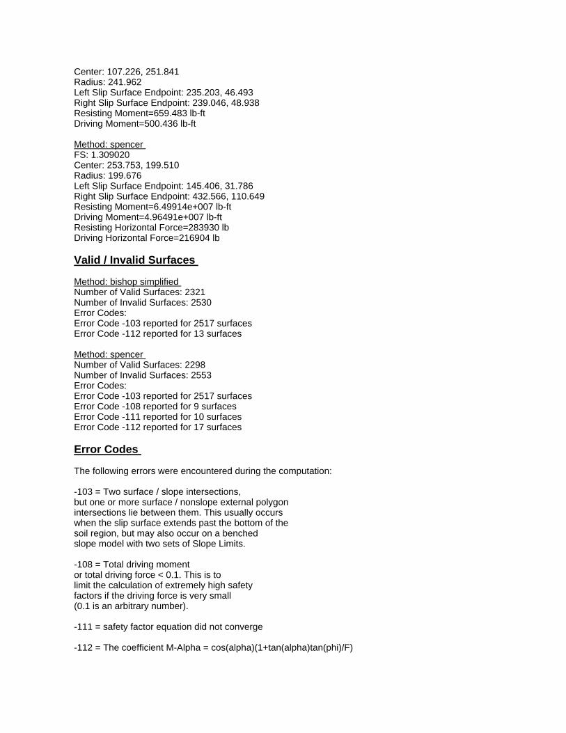
Center: 107.226, 251.841 Radius: 241.962 Left Slip Surface Endpoint: 235.203, 46.493 Right Slip Surface Endpoint: 239.046, 48.938 Resisting Moment=659.483 lb-ft Driving Moment=500.436 lb-ft Method: spencer FS: 1.309020 Center: 253.753, 199.510 Radius: 199.676 Left Slip Surface Endpoint: 145.406, 31.786 Right Slip Surface Endpoint: 432.566, 110.649 Resisting Moment=6.49914e+007 lb-ft Driving Moment=4.96491e+007 lb-ft Resisting Horizontal Force=283930 lb Driving Horizontal Force=216904 lb Valid / Invalid Surfaces Method: bishop simplified Number of Valid Surfaces: 2321 Number of Invalid Surfaces: 2530 Error Codes: Error Code -103 reported for 2517 surfaces Error Code -112 reported for 13 surfaces Method: spencer Number of Valid Surfaces: 2298 Number of Invalid Surfaces: 2553 Error Codes: Error Code -103 reported for 2517 surfaces Error Code -108 reported for 9 surfaces Error Code -111 reported for 10 surfaces Error Code -112 reported for 17 surfaces Error Codes The following errors were encountered during the computation: -103 = Two surface / slope intersections, but one or more surface / nonslope external polygon intersections lie between them. This usually occurs when the slip surface extends past the bottom of the soil region, but may also occur on a benched slope model with two sets of Slope Limits. -108 = Total driving moment or total driving force < 0.1. This is to limit the calculation of extremely high safety factors if the driving force is very small (0.1 is an arbitrary number). -111 = safety factor equation did not converge -112 = The coefficient M-Alpha = cos(alpha)(1+tan(alpha)tan(phi)/F)
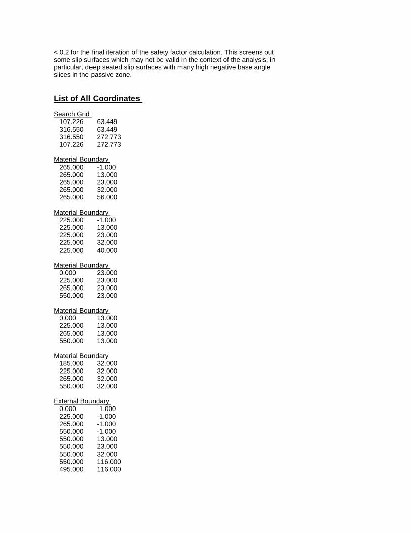
< 0.2 for the final iteration of the safety factor calculation. This screens out some slip surfaces which may not be valid in the context of the analysis, in particular, deep seated slip surfaces with many high negative base angle slices in the passive zone. List of All Coordinates Search Grid 107.226 63.449 316.550 63.449 316.550 272.773 107.226 272.773 Material Boundary 265.000 -1.000 265.000 13.000 265.000 23.000 265.000 32.000 265.000 56.000 Material Boundary 225.000 -1.000 225.000 13.000 225.000 23.000 225.000 32.000 225.000 40.000 Material Boundary 0.000 23.000 225.000 23.000 265.000 23.000 550.000 23.000 Material Boundary 0.000 13.000 225.000 13.000 265.000 13.000 550.000 13.000 Material Boundary 185.000 32.000 225.000 32.000 265.000 32.000 550.000 32.000 External Boundary 0.000 -1.000 225.000 -1.000 265.000 -1.000 550.000 -1.000 550.000 13.000 550.000 23.000 550.000 32.000 550.000 116.000 495.000 116.000
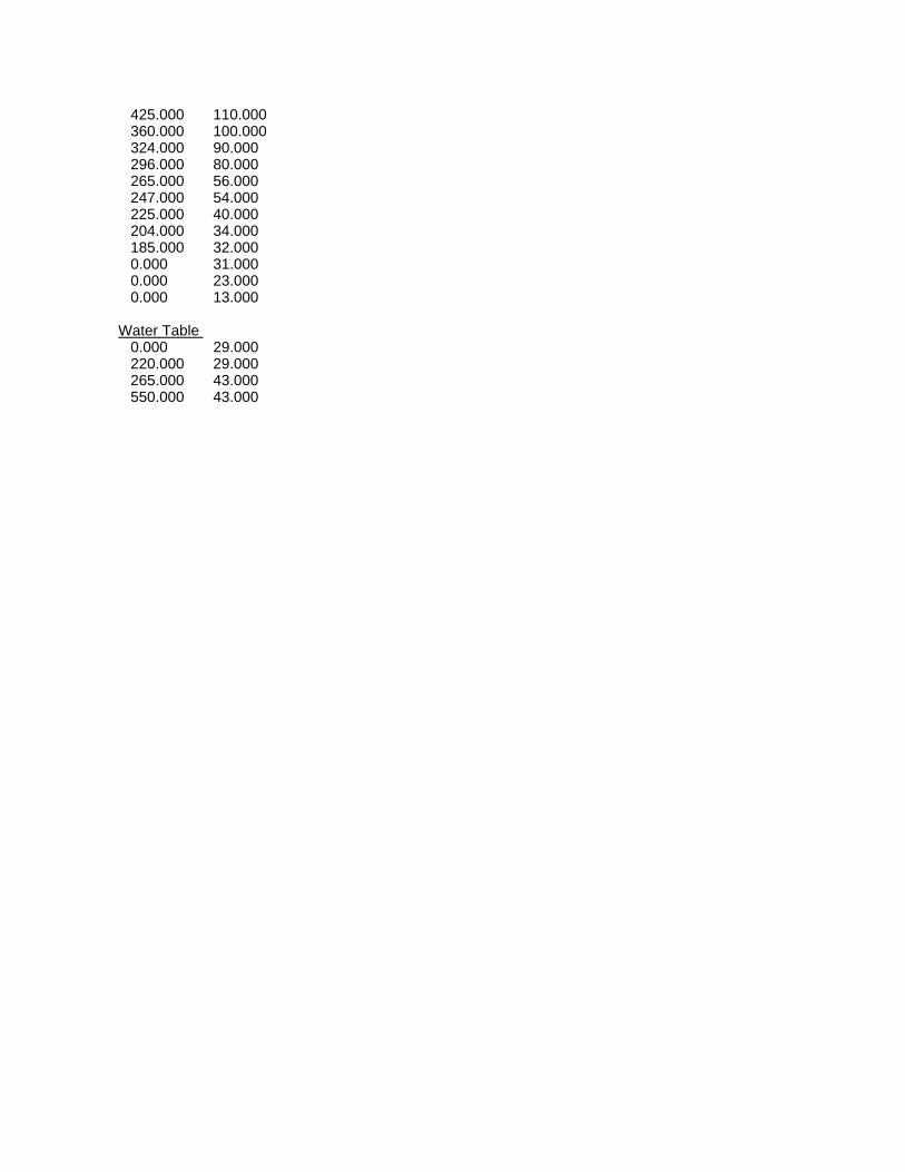
425.000 110.000 360.000 100.000 324.000 90.000 296.000 80.000 265.000 56.000 247.000 54.000 225.000 40.000 204.000 34.000 185.000 32.000 0.000 31.000 0.000 23.000 0.000 13.000 Water Table 0.000 29.000 220.000 29.000 265.000 43.000 550.000 43.000

1.21.2
W
W
1.21.2
Concept CProposed Section D-DNewbury BBC Su Profile
250
200
150
100
500
100 150 200 250 300 350 400 450

Slide Analysis Information Document Name File Name: NBBC_DD_Proposed.sli Project Settings Project Title: SLIDE - An Interactive Slope Stability Program Failure Direction: Right to Left Units of Measurement: Imperial Units Pore Fluid Unit Weight: 62.4 lb/ft3 Groundwater Method: Water Surfaces Data Output: Standard Calculate Excess Pore Pressure: Off Allow Ru with Water Surfaces or Grids: Off Random Numbers: Pseudo-random Seed Random Number Seed: 10116 Random Number Generation Method: Park and Miller v.3 Analysis Methods Analysis Methods used: Bishop simplified Spencer Number of slices: 25 Tolerance: 0.005 Maximum number of iterations: 50 Surface Options Surface Type: Circular Search Method: Grid Search Radius increment: 10 Composite Surfaces: Disabled Reverse Curvature: Create Tension Crack Minimum Elevation: Not Defined Minimum Depth: Not Defined Material Properties Material: Existing Berm Strength Type: Mohr-Coulomb Unit Weight: 118.5 lb/ft3 Cohesion: 0 psf Friction Angle: 40 degrees Water Surface: Water Table Custom Hu value: 1 Material: Landfill Waste Strength Type: Mohr-Coulomb Unit Weight: 70 lb/ft3 Cohesion: 200 psf Friction Angle: 25 degrees

Water Surface: Water Table Custom Hu value: 1 Material: Clay Zone 1B Strength Type: Undrained Unit Weight: 115 lb/ft3 Cohesion Type: Constant Cohesion: 587 psf Water Surface: None Material: Clay Zone 1C Strength Type: Undrained Unit Weight: 115 lb/ft3 Cohesion Type: Constant Cohesion: 687 psf Water Surface: None Material: Clay Zone 2B Strength Type: Undrained Unit Weight: 115 lb/ft3 Cohesion Type: Constant Cohesion: 910 psf Water Surface: None Material: Clay Zone 2C Strength Type: Undrained Unit Weight: 115 lb/ft3 Cohesion Type: Constant Cohesion: 861 psf Water Surface: None Material: Clay Zone 3B Strength Type: Undrained Unit Weight: 115 lb/ft3 Cohesion Type: Constant Cohesion: 1086 psf Water Surface: None Material: Clay Zone 3C Strength Type: Undrained Unit Weight: 115 lb/ft3 Cohesion Type: Constant Cohesion: 1220 psf Water Surface: None Material: Structural Fill Strength Type: Mohr-Coulomb Unit Weight: 130 lb/ft3 Cohesion: 0 psf Friction Angle: 40 degrees Water Surface: Water Table Custom Hu value: 1 Material: Fill Strength Type: Mohr-Coulomb Unit Weight: 118.5 lb/ft3 Cohesion: 0 psf

Friction Angle: 30 degrees Water Surface: Water Table Custom Hu value: 1 Global Minimums Method: bishop simplified FS: 1.205630 Center: 211.888, 84.382 Radius: 80.173 Left Slip Surface Endpoint: 151.351, 31.818 Right Slip Surface Endpoint: 291.975, 80.658 Resisting Moment=1.06793e+007 lb-ft Driving Moment=8.85785e+006 lb-ft Method: spencer FS: 1.205960 Center: 222.354, 126.246 Radius: 126.105 Left Slip Surface Endpoint: 138.849, 31.751 Right Slip Surface Endpoint: 345.359, 98.453 Resisting Moment=2.62353e+007 lb-ft Driving Moment=2.17548e+007 lb-ft Resisting Horizontal Force=170988 lb Driving Horizontal Force=141786 lb Valid / Invalid Surfaces Method: bishop simplified Number of Valid Surfaces: 2359 Number of Invalid Surfaces: 2492 Error Codes: Error Code -103 reported for 2470 surfaces Error Code -112 reported for 22 surfaces Method: spencer Number of Valid Surfaces: 2330 Number of Invalid Surfaces: 2521 Error Codes: Error Code -103 reported for 2470 surfaces Error Code -108 reported for 13 surfaces Error Code -111 reported for 13 surfaces Error Code -112 reported for 25 surfaces Error Codes The following errors were encountered during the computation: -103 = Two surface / slope intersections, but one or more surface / nonslope external polygon intersections lie between them. This usually occurs when the slip surface extends past the bottom of the soil region, but may also occur on a benched slope model with two sets of Slope Limits. -108 = Total driving moment
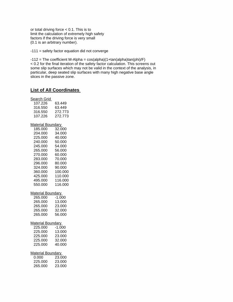
or total driving force < 0.1. This is to limit the calculation of extremely high safety factors if the driving force is very small (0.1 is an arbitrary number). -111 = safety factor equation did not converge -112 = The coefficient M-Alpha = cos(alpha)(1+tan(alpha)tan(phi)/F) < 0.2 for the final iteration of the safety factor calculation. This screens out some slip surfaces which may not be valid in the context of the analysis, in particular, deep seated slip surfaces with many high negative base angle slices in the passive zone. List of All Coordinates Search Grid 107.226 63.449 316.550 63.449 316.550 272.773 107.226 272.773 Material Boundary 185.000 32.000 204.000 34.000 225.000 40.000 240.000 50.000 245.000 54.000 265.000 56.000 270.000 60.000 283.000 70.000 296.000 80.000 324.000 90.000 360.000 100.000 425.000 110.000 495.000 116.000 550.000 116.000 Material Boundary 265.000 -1.000 265.000 13.000 265.000 23.000 265.000 32.000 265.000 56.000 Material Boundary 225.000 -1.000 225.000 13.000 225.000 23.000 225.000 32.000 225.000 40.000 Material Boundary 0.000 23.000 225.000 23.000 265.000 23.000

550.000 23.000 Material Boundary 0.000 13.000 225.000 13.000 265.000 13.000 550.000 13.000 Material Boundary 185.000 32.000 225.000 32.000 265.000 32.000 550.000 32.000 External Boundary 0.000 -1.000 225.000 -1.000 265.000 -1.000 550.000 -1.000 550.000 13.000 550.000 23.000 550.000 32.000 550.000 116.000 550.000 118.000 495.000 118.000 450.000 116.000 410.000 110.000 350.000 100.000 320.000 90.000 290.000 80.000 270.000 70.000 250.000 60.000 230.000 50.000 210.000 40.000 185.000 32.000 0.000 31.000 0.000 23.000 0.000 13.000 Water Table 0.000 29.000 220.000 29.000 265.000 43.000 550.000 43.000

1.01.0
W
1.01.0
Concept CExisting Conditions Section A-ASu = 900 psf
250
200
150
100
500
150 200 250 300 350 400 450 500

Slide Analysis Information Document Name File Name: 900_AA_Existing.sli Project Settings Project Title: SLIDE - An Interactive Slope Stability Program Failure Direction: Right to Left Units of Measurement: Imperial Units Pore Fluid Unit Weight: 62.4 lb/ft3 Groundwater Method: Water Surfaces Data Output: Standard Calculate Excess Pore Pressure: Off Allow Ru with Water Surfaces or Grids: Off Random Numbers: Pseudo-random Seed Random Number Seed: 10116 Random Number Generation Method: Park and Miller v.3 Analysis Methods Analysis Methods used: Bishop simplified Spencer Number of slices: 25 Tolerance: 0.005 Maximum number of iterations: 50 Surface Options Surface Type: Circular Search Method: Grid Search Radius increment: 10 Composite Surfaces: Disabled Reverse Curvature: Create Tension Crack Minimum Elevation: Not Defined Minimum Depth: Not Defined Material Properties Material: Existing Berm Strength Type: Mohr-Coulomb Unit Weight: 118.5 lb/ft3 Cohesion: 0 psf Friction Angle: 40 degrees Water Surface: Water Table Custom Hu value: 1 Material: Landfill Waste Strength Type: Mohr-Coulomb Unit Weight: 70 lb/ft3 Cohesion: 200 psf Friction Angle: 25 degrees
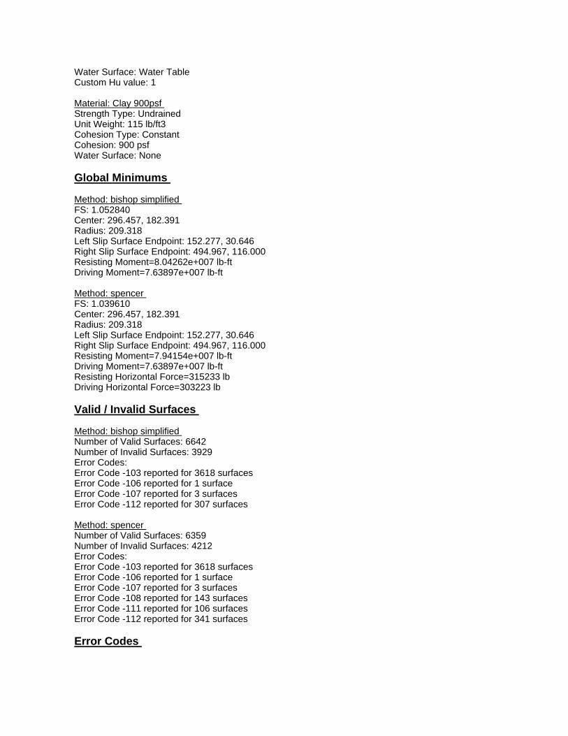
Water Surface: Water Table Custom Hu value: 1 Material: Clay 900psf Strength Type: Undrained Unit Weight: 115 lb/ft3 Cohesion Type: Constant Cohesion: 900 psf Water Surface: None Global Minimums Method: bishop simplified FS: 1.052840 Center: 296.457, 182.391 Radius: 209.318 Left Slip Surface Endpoint: 152.277, 30.646 Right Slip Surface Endpoint: 494.967, 116.000 Resisting Moment=8.04262e+007 lb-ft Driving Moment=7.63897e+007 lb-ft Method: spencer FS: 1.039610 Center: 296.457, 182.391 Radius: 209.318 Left Slip Surface Endpoint: 152.277, 30.646 Right Slip Surface Endpoint: 494.967, 116.000 Resisting Moment=7.94154e+007 lb-ft Driving Moment=7.63897e+007 lb-ft Resisting Horizontal Force=315233 lb Driving Horizontal Force=303223 lb Valid / Invalid Surfaces Method: bishop simplified Number of Valid Surfaces: 6642 Number of Invalid Surfaces: 3929 Error Codes: Error Code -103 reported for 3618 surfaces Error Code -106 reported for 1 surface Error Code -107 reported for 3 surfaces Error Code -112 reported for 307 surfaces Method: spencer Number of Valid Surfaces: 6359 Number of Invalid Surfaces: 4212 Error Codes: Error Code -103 reported for 3618 surfaces Error Code -106 reported for 1 surface Error Code -107 reported for 3 surfaces Error Code -108 reported for 143 surfaces Error Code -111 reported for 106 surfaces Error Code -112 reported for 341 surfaces Error Codes

The following errors were encountered during the computation: -103 = Two surface / slope intersections, but one or more surface / nonslope external polygon intersections lie between them. This usually occurs when the slip surface extends past the bottom of the soil region, but may also occur on a benched slope model with two sets of Slope Limits. -106 = Average slice width is less than 0.0001 * (maximum horizontal extent of soil region). This limitation is imposed to avoid numerical errors which may result from too many slices, or too small a slip region. -107 = Total driving moment or total driving force is negative. This will occur if the wrong failure direction is specified, or if high external or anchor loads are applied against the failure direction. -108 = Total driving moment or total driving force < 0.1. This is to limit the calculation of extremely high safety factors if the driving force is very small (0.1 is an arbitrary number). -111 = safety factor equation did not converge -112 = The coefficient M-Alpha = cos(alpha)(1+tan(alpha)tan(phi)/F) < 0.2 for the final iteration of the safety factor calculation. This screens out some slip surfaces which may not be valid in the context of the analysis, in particular, deep seated slip surfaces with many high negative base angle slices in the passive zone. List of All Coordinates Search Grid 108.979 29.000 364.630 29.000 364.630 284.651 108.979 284.651 Material Boundary 200.000 31.000 215.000 31.000 257.000 31.000 265.000 31.000 550.000 31.000 Material Boundary 265.000 31.000 265.000 54.000 External Boundary

0.000 -27.000 215.000 -27.000 265.000 -27.000 550.000 -27.000 550.000 13.000 550.000 23.000 550.000 31.000 550.000 116.000 490.000 116.000 430.000 110.000 360.000 100.000 300.000 82.000 265.000 54.000 245.000 54.000 215.000 34.000 200.000 31.000 185.000 31.000 0.000 29.000 0.000 23.000 0.000 13.000 Water Table 0.000 29.000 220.000 29.000 265.000 43.000 550.000 43.000
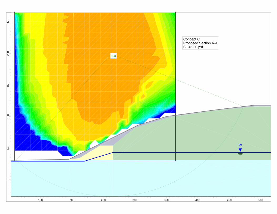
1.01.0
W
1.01.0
Concept CProposed Section A-ASu = 900 psf
250
200
150
100
500
150 200 250 300 350 400 450 500

Slide Analysis Information Document Name File Name: 900_AA_Proposed.sli Project Settings Project Title: SLIDE - An Interactive Slope Stability Program Failure Direction: Right to Left Units of Measurement: Imperial Units Pore Fluid Unit Weight: 62.4 lb/ft3 Groundwater Method: Water Surfaces Data Output: Standard Calculate Excess Pore Pressure: Off Allow Ru with Water Surfaces or Grids: Off Random Numbers: Pseudo-random Seed Random Number Seed: 10116 Random Number Generation Method: Park and Miller v.3 Analysis Methods Analysis Methods used: Bishop simplified Spencer Number of slices: 25 Tolerance: 0.005 Maximum number of iterations: 50 Surface Options Surface Type: Circular Search Method: Grid Search Radius increment: 10 Composite Surfaces: Disabled Reverse Curvature: Create Tension Crack Minimum Elevation: Not Defined Minimum Depth: Not Defined Material Properties Material: Existing Berm Strength Type: Mohr-Coulomb Unit Weight: 118.5 lb/ft3 Cohesion: 0 psf Friction Angle: 40 degrees Water Surface: Water Table Custom Hu value: 1 Material: Landfill Waste Strength Type: Mohr-Coulomb Unit Weight: 70 lb/ft3 Cohesion: 200 psf Friction Angle: 25 degrees

Water Surface: Water Table Custom Hu value: 1 Material: Structural Fill Strength Type: Mohr-Coulomb Unit Weight: 130 lb/ft3 Cohesion: 0 psf Friction Angle: 40 degrees Water Surface: Water Table Custom Hu value: 1 Material: Clay 900psf Strength Type: Undrained Unit Weight: 115 lb/ft3 Cohesion Type: Constant Cohesion: 900 psf Water Surface: None Global Minimums Method: bishop simplified FS: 1.055090 Center: 262.370, 199.434 Radius: 226.189 Left Slip Surface Endpoint: 111.716, 30.719 Right Slip Surface Endpoint: 472.550, 115.852 Resisting Moment=9.03587e+007 lb-ft Driving Moment=8.56407e+007 lb-ft Method: spencer FS: 1.043560 Center: 262.370, 199.434 Radius: 226.189 Left Slip Surface Endpoint: 111.716, 30.719 Right Slip Surface Endpoint: 472.550, 115.852 Resisting Moment=8.93709e+007 lb-ft Driving Moment=8.56407e+007 lb-ft Resisting Horizontal Force=332833 lb Driving Horizontal Force=318941 lb Valid / Invalid Surfaces Method: bishop simplified Number of Valid Surfaces: 6625 Number of Invalid Surfaces: 3946 Error Codes: Error Code -103 reported for 3597 surfaces Error Code -112 reported for 349 surfaces Method: spencer Number of Valid Surfaces: 6341 Number of Invalid Surfaces: 4230 Error Codes: Error Code -103 reported for 3597 surfaces Error Code -108 reported for 150 surfaces Error Code -111 reported for 101 surfaces Error Code -112 reported for 382 surfaces

Error Codes The following errors were encountered during the computation: -103 = Two surface / slope intersections, but one or more surface / nonslope external polygon intersections lie between them. This usually occurs when the slip surface extends past the bottom of the soil region, but may also occur on a benched slope model with two sets of Slope Limits. -108 = Total driving moment or total driving force < 0.1. This is to limit the calculation of extremely high safety factors if the driving force is very small (0.1 is an arbitrary number). -111 = safety factor equation did not converge -112 = The coefficient M-Alpha = cos(alpha)(1+tan(alpha)tan(phi)/F) < 0.2 for the final iteration of the safety factor calculation. This screens out some slip surfaces which may not be valid in the context of the analysis, in particular, deep seated slip surfaces with many high negative base angle slices in the passive zone. List of All Coordinates Search Grid 108.979 29.000 364.630 29.000 364.630 284.651 108.979 284.651 Material Boundary 200.000 23.000 200.000 31.000 Material Boundary 200.000 31.000 257.000 31.000 265.000 31.000 550.000 31.000 Material Boundary 265.000 54.000 300.000 82.000 332.759 91.828 360.000 100.000 430.000 110.000 490.000 116.000 550.000 116.000 Material Boundary 195.000 32.000 195.000 31.000

200.000 31.000 Material Boundary 195.000 32.000 212.000 34.000 245.000 54.000 265.000 54.000 Material Boundary 265.000 31.000 265.000 54.000 External Boundary 0.000 -27.000 200.000 -27.000 265.000 -27.000 550.000 -27.000 550.000 13.000 550.000 23.000 550.000 31.000 550.000 116.000 550.000 118.000 490.000 118.000 425.000 110.000 350.000 100.000 305.000 86.500 195.000 32.000 0.000 29.000 0.000 23.000 0.000 13.000 Water Table 0.000 29.000 220.000 29.000 265.000 43.000 550.000 43.000

1.11.1
W
W
1.11.1
Concept CExisting Condtions Section A-ASu = 1,000 psf
250
200
150
100
500
100 150 200 250 300 350 400 450

Slide Analysis Information Document Name File Name: 1000_AA_Existing.sli Project Settings Project Title: SLIDE - An Interactive Slope Stability Program Failure Direction: Right to Left Units of Measurement: Imperial Units Pore Fluid Unit Weight: 62.4 lb/ft3 Groundwater Method: Water Surfaces Data Output: Standard Calculate Excess Pore Pressure: Off Allow Ru with Water Surfaces or Grids: Off Random Numbers: Pseudo-random Seed Random Number Seed: 10116 Random Number Generation Method: Park and Miller v.3 Analysis Methods Analysis Methods used: Bishop simplified Spencer Number of slices: 25 Tolerance: 0.005 Maximum number of iterations: 50 Surface Options Surface Type: Circular Search Method: Grid Search Radius increment: 10 Composite Surfaces: Disabled Reverse Curvature: Create Tension Crack Minimum Elevation: Not Defined Minimum Depth: Not Defined Material Properties Material: Existing Berm Strength Type: Mohr-Coulomb Unit Weight: 118.5 lb/ft3 Cohesion: 0 psf Friction Angle: 40 degrees Water Surface: Water Table Custom Hu value: 1 Material: Landfill Waste Strength Type: Mohr-Coulomb Unit Weight: 70 lb/ft3 Cohesion: 200 psf Friction Angle: 25 degrees

Water Surface: Water Table Custom Hu value: 1 Material: Clay 1000psf Strength Type: Undrained Unit Weight: 115 lb/ft3 Cohesion Type: Constant Cohesion: 1000 psf Water Surface: None Global Minimums Method: bishop simplified FS: 1.149280 Center: 296.457, 182.391 Radius: 209.318 Left Slip Surface Endpoint: 152.277, 30.646 Right Slip Surface Endpoint: 494.967, 116.000 Resisting Moment=8.77932e+007 lb-ft Driving Moment=7.63897e+007 lb-ft Method: spencer FS: 1.133570 Center: 296.457, 182.391 Radius: 209.318 Left Slip Surface Endpoint: 152.277, 30.646 Right Slip Surface Endpoint: 494.967, 116.000 Resisting Moment=8.65927e+007 lb-ft Driving Moment=7.63897e+007 lb-ft Resisting Horizontal Force=345525 lb Driving Horizontal Force=304813 lb Valid / Invalid Surfaces Method: bishop simplified Number of Valid Surfaces: 6656 Number of Invalid Surfaces: 3915 Error Codes: Error Code -103 reported for 3618 surfaces Error Code -106 reported for 1 surface Error Code -107 reported for 3 surfaces Error Code -112 reported for 293 surfaces Method: spencer Number of Valid Surfaces: 6375 Number of Invalid Surfaces: 4196 Error Codes: Error Code -103 reported for 3618 surfaces Error Code -106 reported for 1 surface Error Code -107 reported for 3 surfaces Error Code -108 reported for 142 surfaces Error Code -111 reported for 104 surfaces Error Code -112 reported for 328 surfaces Error Codes
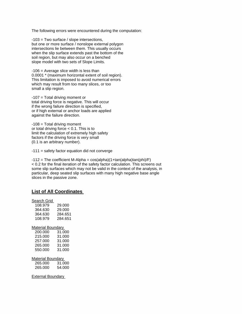
The following errors were encountered during the computation: -103 = Two surface / slope intersections, but one or more surface / nonslope external polygon intersections lie between them. This usually occurs when the slip surface extends past the bottom of the soil region, but may also occur on a benched slope model with two sets of Slope Limits. -106 = Average slice width is less than 0.0001 * (maximum horizontal extent of soil region). This limitation is imposed to avoid numerical errors which may result from too many slices, or too small a slip region. -107 = Total driving moment or total driving force is negative. This will occur if the wrong failure direction is specified, or if high external or anchor loads are applied against the failure direction. -108 = Total driving moment or total driving force < 0.1. This is to limit the calculation of extremely high safety factors if the driving force is very small (0.1 is an arbitrary number). -111 = safety factor equation did not converge -112 = The coefficient M-Alpha = cos(alpha)(1+tan(alpha)tan(phi)/F) < 0.2 for the final iteration of the safety factor calculation. This screens out some slip surfaces which may not be valid in the context of the analysis, in particular, deep seated slip surfaces with many high negative base angle slices in the passive zone. List of All Coordinates Search Grid 108.979 29.000 364.630 29.000 364.630 284.651 108.979 284.651 Material Boundary 200.000 31.000 215.000 31.000 257.000 31.000 265.000 31.000 550.000 31.000 Material Boundary 265.000 31.000 265.000 54.000 External Boundary

0.000 -27.000 215.000 -27.000 265.000 -27.000 550.000 -27.000 550.000 13.000 550.000 23.000 550.000 31.000 550.000 116.000 490.000 116.000 430.000 110.000 360.000 100.000 300.000 82.000 265.000 54.000 245.000 54.000 215.000 34.000 200.000 31.000 185.000 31.000 0.000 29.000 0.000 23.000 0.000 13.000 Water Table 0.000 29.000 220.000 29.000 265.000 43.000 550.000 43.000

1.11.1
W
1.11.1
Concept CProposed Section A-ASu = 1,000 psf
250
200
150
100
500
150 200 250 300 350 400 450 500
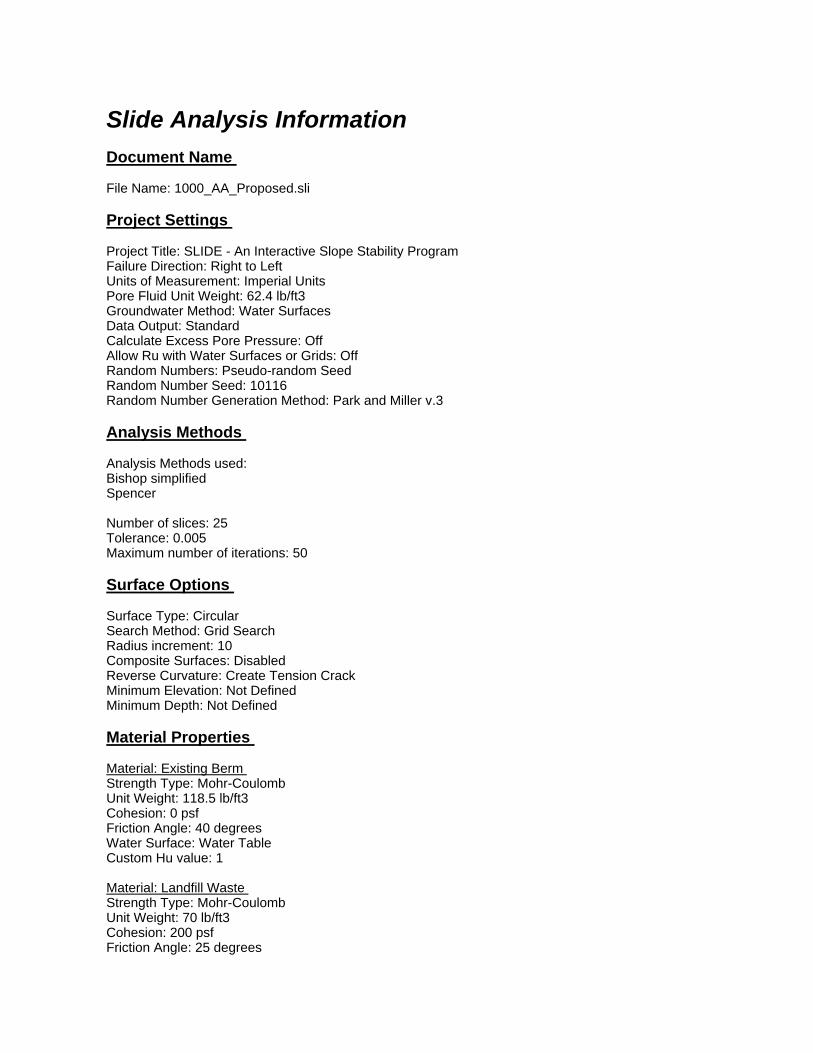
Slide Analysis Information Document Name File Name: 1000_AA_Proposed.sli Project Settings Project Title: SLIDE - An Interactive Slope Stability Program Failure Direction: Right to Left Units of Measurement: Imperial Units Pore Fluid Unit Weight: 62.4 lb/ft3 Groundwater Method: Water Surfaces Data Output: Standard Calculate Excess Pore Pressure: Off Allow Ru with Water Surfaces or Grids: Off Random Numbers: Pseudo-random Seed Random Number Seed: 10116 Random Number Generation Method: Park and Miller v.3 Analysis Methods Analysis Methods used: Bishop simplified Spencer Number of slices: 25 Tolerance: 0.005 Maximum number of iterations: 50 Surface Options Surface Type: Circular Search Method: Grid Search Radius increment: 10 Composite Surfaces: Disabled Reverse Curvature: Create Tension Crack Minimum Elevation: Not Defined Minimum Depth: Not Defined Material Properties Material: Existing Berm Strength Type: Mohr-Coulomb Unit Weight: 118.5 lb/ft3 Cohesion: 0 psf Friction Angle: 40 degrees Water Surface: Water Table Custom Hu value: 1 Material: Landfill Waste Strength Type: Mohr-Coulomb Unit Weight: 70 lb/ft3 Cohesion: 200 psf Friction Angle: 25 degrees

Water Surface: Water Table Custom Hu value: 1 Material: Structural Fill Strength Type: Mohr-Coulomb Unit Weight: 130 lb/ft3 Cohesion: 0 psf Friction Angle: 40 degrees Water Surface: Water Table Custom Hu value: 1 Material: Clay 1000 psf Strength Type: Undrained Unit Weight: 115 lb/ft3 Cohesion Type: Constant Cohesion: 1000 psf Water Surface: None Global Minimums Method: bishop simplified FS: 1.150990 Center: 262.370, 199.434 Radius: 226.189 Left Slip Surface Endpoint: 111.716, 30.719 Right Slip Surface Endpoint: 472.550, 115.852 Resisting Moment=9.85718e+007 lb-ft Driving Moment=8.56407e+007 lb-ft Method: spencer FS: 1.136770 Center: 262.370, 199.434 Radius: 226.189 Left Slip Surface Endpoint: 111.716, 30.719 Right Slip Surface Endpoint: 472.550, 115.852 Resisting Moment=9.73536e+007 lb-ft Driving Moment=8.56407e+007 lb-ft Resisting Horizontal Force=364501 lb Driving Horizontal Force=320646 lb Valid / Invalid Surfaces Method: bishop simplified Number of Valid Surfaces: 6635 Number of Invalid Surfaces: 3936 Error Codes: Error Code -103 reported for 3597 surfaces Error Code -112 reported for 339 surfaces Method: spencer Number of Valid Surfaces: 6358 Number of Invalid Surfaces: 4213 Error Codes: Error Code -103 reported for 3597 surfaces Error Code -108 reported for 142 surfaces Error Code -111 reported for 111 surfaces Error Code -112 reported for 363 surfaces

Error Codes The following errors were encountered during the computation: -103 = Two surface / slope intersections, but one or more surface / nonslope external polygon intersections lie between them. This usually occurs when the slip surface extends past the bottom of the soil region, but may also occur on a benched slope model with two sets of Slope Limits. -108 = Total driving moment or total driving force < 0.1. This is to limit the calculation of extremely high safety factors if the driving force is very small (0.1 is an arbitrary number). -111 = safety factor equation did not converge -112 = The coefficient M-Alpha = cos(alpha)(1+tan(alpha)tan(phi)/F) < 0.2 for the final iteration of the safety factor calculation. This screens out some slip surfaces which may not be valid in the context of the analysis, in particular, deep seated slip surfaces with many high negative base angle slices in the passive zone. List of All Coordinates Search Grid 108.979 29.000 364.630 29.000 364.630 284.651 108.979 284.651 Material Boundary 200.000 23.000 200.000 31.000 Material Boundary 200.000 31.000 257.000 31.000 265.000 31.000 550.000 31.000 Material Boundary 265.000 54.000 300.000 82.000 332.759 91.828 360.000 100.000 430.000 110.000 490.000 116.000 550.000 116.000 Material Boundary 195.000 32.000 195.000 31.000
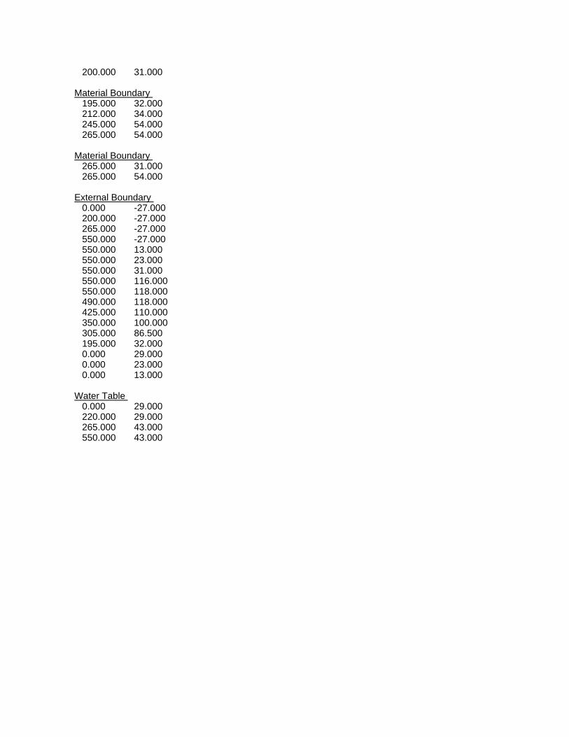
200.000 31.000 Material Boundary 195.000 32.000 212.000 34.000 245.000 54.000 265.000 54.000 Material Boundary 265.000 31.000 265.000 54.000 External Boundary 0.000 -27.000 200.000 -27.000 265.000 -27.000 550.000 -27.000 550.000 13.000 550.000 23.000 550.000 31.000 550.000 116.000 550.000 118.000 490.000 118.000 425.000 110.000 350.000 100.000 305.000 86.500 195.000 32.000 0.000 29.000 0.000 23.000 0.000 13.000 Water Table 0.000 29.000 220.000 29.000 265.000 43.000 550.000 43.000

1.21.2
W
1.21.2
Concept CExisting Conditions Section A-ASu = 1,100 psf
250
200
150
100
500
100 150 200 250 300 350 400 450 500

Slide Analysis Information Document Name File Name: 1100_AA_Existing.sli Project Settings Project Title: SLIDE - An Interactive Slope Stability Program Failure Direction: Right to Left Units of Measurement: Imperial Units Pore Fluid Unit Weight: 62.4 lb/ft3 Groundwater Method: Water Surfaces Data Output: Standard Calculate Excess Pore Pressure: Off Allow Ru with Water Surfaces or Grids: Off Random Numbers: Pseudo-random Seed Random Number Seed: 10116 Random Number Generation Method: Park and Miller v.3 Analysis Methods Analysis Methods used: Bishop simplified Spencer Number of slices: 25 Tolerance: 0.005 Maximum number of iterations: 50 Surface Options Surface Type: Circular Search Method: Grid Search Radius increment: 10 Composite Surfaces: Disabled Reverse Curvature: Create Tension Crack Minimum Elevation: Not Defined Minimum Depth: Not Defined Material Properties Material: Existing Berm Strength Type: Mohr-Coulomb Unit Weight: 118.5 lb/ft3 Cohesion: 0 psf Friction Angle: 40 degrees Water Surface: Water Table Custom Hu value: 1 Material: Landfill Waste Strength Type: Mohr-Coulomb Unit Weight: 70 lb/ft3 Cohesion: 200 psf Friction Angle: 25 degrees
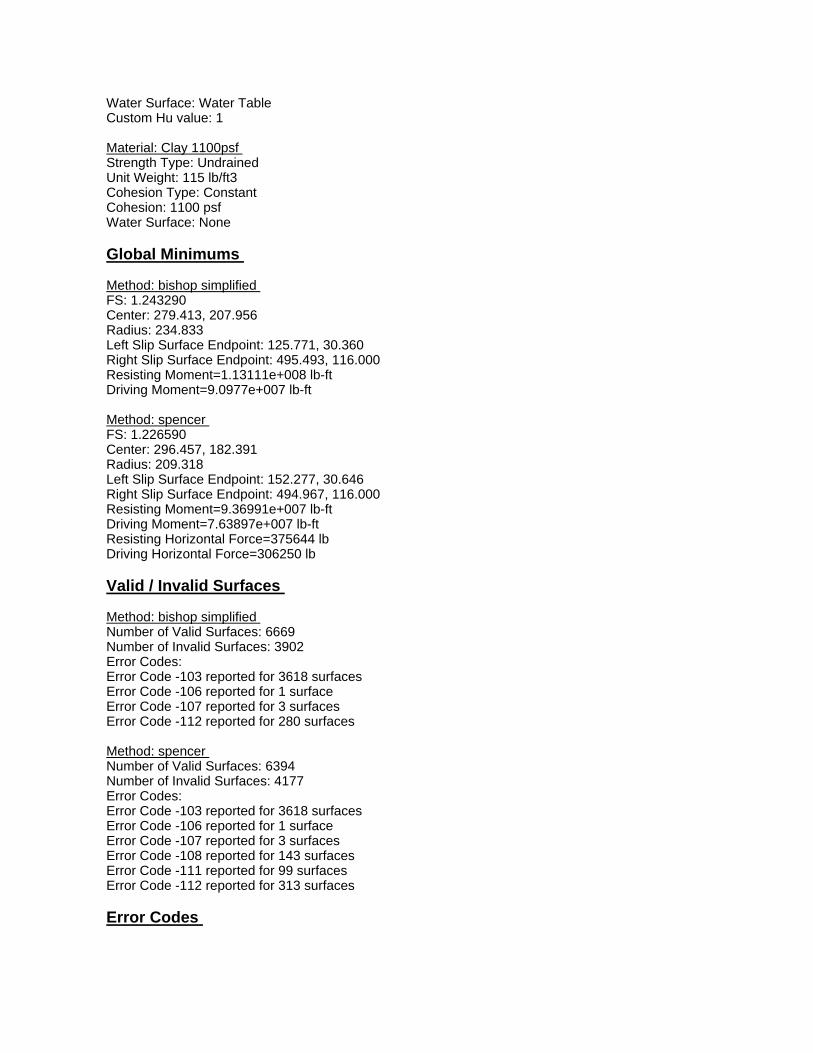
Water Surface: Water Table Custom Hu value: 1 Material: Clay 1100psf Strength Type: Undrained Unit Weight: 115 lb/ft3 Cohesion Type: Constant Cohesion: 1100 psf Water Surface: None Global Minimums Method: bishop simplified FS: 1.243290 Center: 279.413, 207.956 Radius: 234.833 Left Slip Surface Endpoint: 125.771, 30.360 Right Slip Surface Endpoint: 495.493, 116.000 Resisting Moment=1.13111e+008 lb-ft Driving Moment=9.0977e+007 lb-ft Method: spencer FS: 1.226590 Center: 296.457, 182.391 Radius: 209.318 Left Slip Surface Endpoint: 152.277, 30.646 Right Slip Surface Endpoint: 494.967, 116.000 Resisting Moment=9.36991e+007 lb-ft Driving Moment=7.63897e+007 lb-ft Resisting Horizontal Force=375644 lb Driving Horizontal Force=306250 lb Valid / Invalid Surfaces Method: bishop simplified Number of Valid Surfaces: 6669 Number of Invalid Surfaces: 3902 Error Codes: Error Code -103 reported for 3618 surfaces Error Code -106 reported for 1 surface Error Code -107 reported for 3 surfaces Error Code -112 reported for 280 surfaces Method: spencer Number of Valid Surfaces: 6394 Number of Invalid Surfaces: 4177 Error Codes: Error Code -103 reported for 3618 surfaces Error Code -106 reported for 1 surface Error Code -107 reported for 3 surfaces Error Code -108 reported for 143 surfaces Error Code -111 reported for 99 surfaces Error Code -112 reported for 313 surfaces Error Codes

The following errors were encountered during the computation: -103 = Two surface / slope intersections, but one or more surface / nonslope external polygon intersections lie between them. This usually occurs when the slip surface extends past the bottom of the soil region, but may also occur on a benched slope model with two sets of Slope Limits. -106 = Average slice width is less than 0.0001 * (maximum horizontal extent of soil region). This limitation is imposed to avoid numerical errors which may result from too many slices, or too small a slip region. -107 = Total driving moment or total driving force is negative. This will occur if the wrong failure direction is specified, or if high external or anchor loads are applied against the failure direction. -108 = Total driving moment or total driving force < 0.1. This is to limit the calculation of extremely high safety factors if the driving force is very small (0.1 is an arbitrary number). -111 = safety factor equation did not converge -112 = The coefficient M-Alpha = cos(alpha)(1+tan(alpha)tan(phi)/F) < 0.2 for the final iteration of the safety factor calculation. This screens out some slip surfaces which may not be valid in the context of the analysis, in particular, deep seated slip surfaces with many high negative base angle slices in the passive zone. List of All Coordinates Search Grid 108.979 29.000 364.630 29.000 364.630 284.651 108.979 284.651 Material Boundary 200.000 31.000 215.000 31.000 257.000 31.000 265.000 31.000 550.000 31.000 Material Boundary 265.000 31.000 265.000 54.000 External Boundary

0.000 -27.000 215.000 -27.000 265.000 -27.000 550.000 -27.000 550.000 13.000 550.000 23.000 550.000 31.000 550.000 116.000 490.000 116.000 430.000 110.000 360.000 100.000 300.000 82.000 265.000 54.000 245.000 54.000 215.000 34.000 200.000 31.000 185.000 31.000 0.000 29.000 0.000 23.000 0.000 13.000 Water Table 0.000 29.000 220.000 29.000 265.000 43.000 550.000 43.000
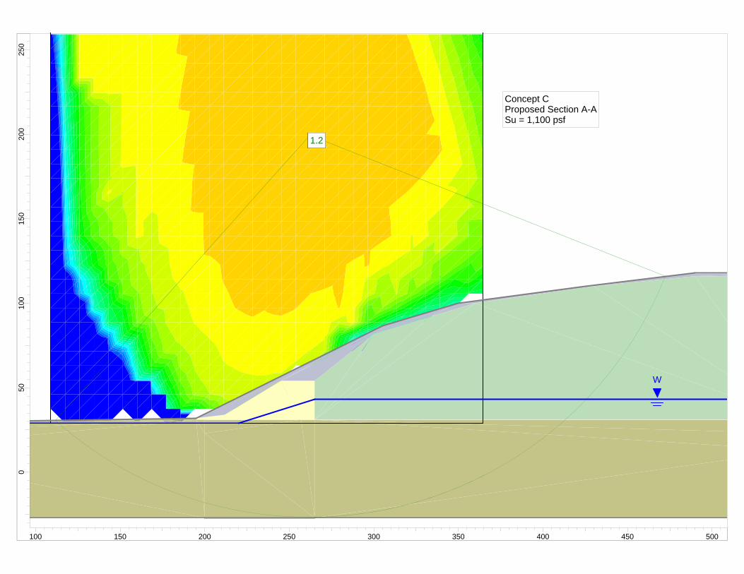
1.21.2
W
1.21.2
Concept CProposed Section A-ASu = 1,100 psf
250
200
150
100
500
100 150 200 250 300 350 400 450 500

Slide Analysis Information Document Name File Name: 1100_AA_Proposed.sli Project Settings Project Title: SLIDE - An Interactive Slope Stability Program Failure Direction: Right to Left Units of Measurement: Imperial Units Pore Fluid Unit Weight: 62.4 lb/ft3 Groundwater Method: Water Surfaces Data Output: Standard Calculate Excess Pore Pressure: Off Allow Ru with Water Surfaces or Grids: Off Random Numbers: Pseudo-random Seed Random Number Seed: 10116 Random Number Generation Method: Park and Miller v.3 Analysis Methods Analysis Methods used: Bishop simplified Spencer Number of slices: 25 Tolerance: 0.005 Maximum number of iterations: 50 Surface Options Surface Type: Circular Search Method: Grid Search Radius increment: 10 Composite Surfaces: Disabled Reverse Curvature: Create Tension Crack Minimum Elevation: Not Defined Minimum Depth: Not Defined Material Properties Material: Existing Berm Strength Type: Mohr-Coulomb Unit Weight: 118.5 lb/ft3 Cohesion: 0 psf Friction Angle: 40 degrees Water Surface: Water Table Custom Hu value: 1 Material: Landfill Waste Strength Type: Mohr-Coulomb Unit Weight: 70 lb/ft3 Cohesion: 200 psf Friction Angle: 25 degrees

Water Surface: Water Table Custom Hu value: 1 Material: Structural Fill Strength Type: Mohr-Coulomb Unit Weight: 130 lb/ft3 Cohesion: 0 psf Friction Angle: 40 degrees Water Surface: Water Table Custom Hu value: 1 Material: Clay 1100 psf Strength Type: Undrained Unit Weight: 115 lb/ft3 Cohesion Type: Constant Cohesion: 1100 psf Water Surface: None Global Minimums Method: bishop simplified FS: 1.245550 Center: 262.370, 199.434 Radius: 226.189 Left Slip Surface Endpoint: 111.716, 30.719 Right Slip Surface Endpoint: 472.550, 115.852 Resisting Moment=1.0667e+008 lb-ft Driving Moment=8.56407e+007 lb-ft Method: spencer FS: 1.229800 Center: 262.370, 199.434 Radius: 226.189 Left Slip Surface Endpoint: 111.716, 30.719 Right Slip Surface Endpoint: 472.550, 115.852 Resisting Moment=1.05321e+008 lb-ft Driving Moment=8.56407e+007 lb-ft Resisting Horizontal Force=395972 lb Driving Horizontal Force=321980 lb Valid / Invalid Surfaces Method: bishop simplified Number of Valid Surfaces: 6643 Number of Invalid Surfaces: 3928 Error Codes: Error Code -103 reported for 3597 surfaces Error Code -112 reported for 331 surfaces Method: spencer Number of Valid Surfaces: 6372 Number of Invalid Surfaces: 4199 Error Codes: Error Code -103 reported for 3597 surfaces Error Code -108 reported for 142 surfaces Error Code -111 reported for 106 surfaces Error Code -112 reported for 354 surfaces

Error Codes The following errors were encountered during the computation: -103 = Two surface / slope intersections, but one or more surface / nonslope external polygon intersections lie between them. This usually occurs when the slip surface extends past the bottom of the soil region, but may also occur on a benched slope model with two sets of Slope Limits. -108 = Total driving moment or total driving force < 0.1. This is to limit the calculation of extremely high safety factors if the driving force is very small (0.1 is an arbitrary number). -111 = safety factor equation did not converge -112 = The coefficient M-Alpha = cos(alpha)(1+tan(alpha)tan(phi)/F) < 0.2 for the final iteration of the safety factor calculation. This screens out some slip surfaces which may not be valid in the context of the analysis, in particular, deep seated slip surfaces with many high negative base angle slices in the passive zone. List of All Coordinates Search Grid 108.979 29.000 364.630 29.000 364.630 284.651 108.979 284.651 Material Boundary 200.000 23.000 200.000 31.000 Material Boundary 200.000 31.000 257.000 31.000 265.000 31.000 550.000 31.000 Material Boundary 265.000 54.000 300.000 82.000 332.759 91.828 360.000 100.000 430.000 110.000 490.000 116.000 550.000 116.000 Material Boundary 195.000 32.000 195.000 31.000

200.000 31.000 Material Boundary 195.000 32.000 212.000 34.000 245.000 54.000 265.000 54.000 Material Boundary 265.000 31.000 265.000 54.000 External Boundary 0.000 -27.000 200.000 -27.000 265.000 -27.000 550.000 -27.000 550.000 13.000 550.000 23.000 550.000 31.000 550.000 116.000 550.000 118.000 490.000 118.000 425.000 110.000 350.000 100.000 305.000 86.500 195.000 32.000 0.000 29.000 0.000 23.000 0.000 13.000 Water Table 0.000 29.000 220.000 29.000 265.000 43.000 550.000 43.000

Concept CExisting Conditions Section A-ASu = 900 psfWedge Analysis
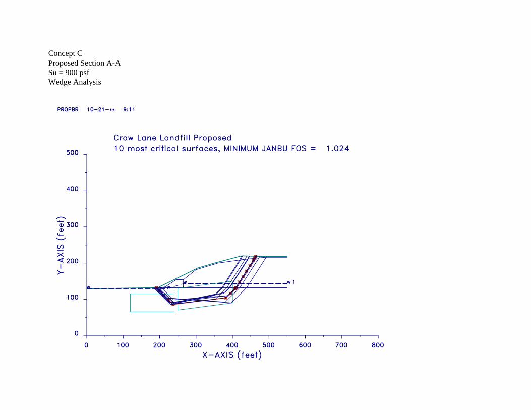
Concept CProposed Section A-ASu = 900 psfWedge Analysis
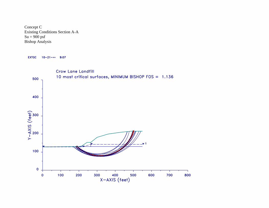
Concept CExisting Conditions Section A-ASu = 900 psfBishop Analysis

Concept CProposed Section A-ASu = 900 psfBishop Analysis