slot diffusers for wall installation – type vsd35-3-az€¦ · type vsd35-3-az. 2. slot diffusers...
TRANSCRIPT
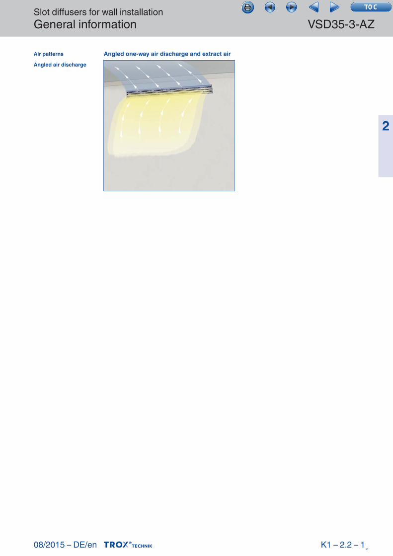
Angled one-wayair discharge and extract air
Wall installation
08/2015 – DE/en
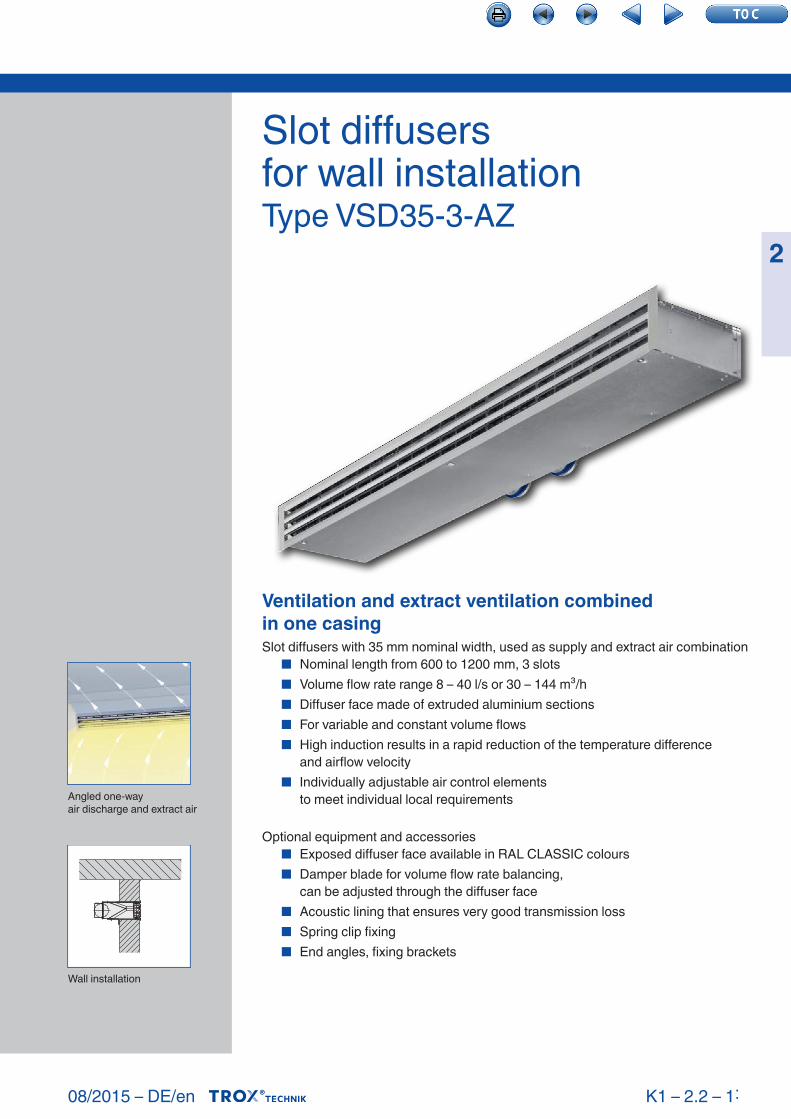
Slot diffusersfor wall instal lationType VSD35-3-AZ
2
Slot diffusers with 35 mm nominal width, used as supply and extract air combination ■ Nominal length from 600 to 1200 mm, 3 slots ■ Volume flow rate range 8 – 40 l/s or 30 – 144 m³/h ■ Diffuser face made of extruded aluminium sections ■ For variable and constant volume flows ■ High induction results in a rapid reduction of the temperature difference
and airflow velocity ■ Individually adjustable air control elements
to meet individual local requirements
Optional equipment and accessories ■ Exposed diffuser face available in RAL CLASSIC colours ■ Damper blade for volume flow rate balancing,
can be adjusted through the diffuser face ■ Acoustic lining that ensures very good transmission loss ■ Spring clip fixing ■ End angles, fixing brackets
VSD35-3-AZ 2.2 –
X XVSD35-3-AZtestregistrierung
K1 – 2.2 – 1˸
Ventilation and extract ventilation combinedin one casing
Slot diffusers for wall installationGeneral information VSD35-3-AZ
08/2015 – DE/en
2
Type
VSD35-3-AZ General information 2.2 – 14Order code 2.2 – 18Quick sizing 2.2 – 19Dimensions and weight 2.2 – 21Installation details 2.2 – 25Specification text 2.2 – 26
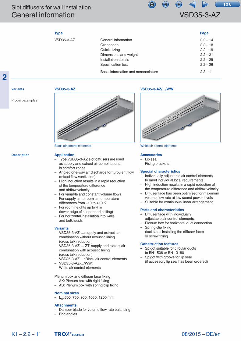
Application– Type VSD35-3-AZ slot diffusers are used as supply and extract air combinations in comfort zones– Angled one-way air discharge for turbulent flow
(mixed flow ventilation)– High induction results in a rapid reduction of the temperature difference and airflow velocity– For variable and constant volume flows– For supply air to room air temperature
differences from –10 to +10 K– For room heights up to 4 m (lower edge of suspended ceiling)– For horizontal installation into walls and bulkheads
Variants– VSD35-3-AZ-...: supply and extract air
combination without acoustic lining (cross talk reduction)– VSD35-3-AZ-...-ZT: supply and extract air
combination with acoustic lining (cross talk reduction)– VSD35-3-AZ-...: Black air control elements– VSD35-3-AZ-.../WW: White air control elements
Plenum box and diffuser face fixing– AK: Plenum box with rigid fixing– AS: Plenum box with spring clip fixing
Nominal sizes– LN: 600, 750, 900, 1050, 1200 mm
Attachments– Damper blade for volume flow rate balancing– End angles
Accessories– Lip seal– Fixing brackets
Special characteristics– Individually adjustable air control elements to meet individual local requirements– High induction results in a rapid reduction of
the temperature difference and airflow velocity– Diffuser face has been optimised for maximum
volume flow rate at low sound power levels– Suitable for continuous linear arrangement
Parts and characteristics– Diffuser face with individually adjustable air control elements– Plenum box for horizontal duct connection– Spring clip fixing (facilitates installing the diffuser face) or screw fixing
Construction features– Spigot suitable for circular ducts to EN 1506 or EN 13180– Spigot with groove for lip seal (if accessory lip seal has been ordered)
Basic information and nomenclature 2.3 – 1
Page
K1 – 2.2 – 1˹
Variants
Product examples
Description
Black air control elements White air control elements
VSD35-3-AZ VSD35-3-AZ/.../WW
Slot diffusers for wall installationGeneral information
08/2015 – DE/en
VSD35-3-AZ
2
Materials and surfaces– Diffuser face made from extruded aluminium sections– Air control elements made of plastic, UL 94, V- 0, flame retardant– Plenum box and fixing brackets made of galvanised sheet steel– End angle made of aluminium– Lip seal made of rubber– Acoustic lining is mineral wool– Diffuser face with anodised finish, E6-C-0, natural colour– P1: Powder-coated, RAL CLASSIC colour– Air control elements similar to RAL 9005, black– WW: Air control elements similar to RAL 9010, white
Mineral wool– To EN 13501, fire rating class A1, non- combustible– RAL quality mark RAL-GZ 388– Biosoluble and hence hygienically safe according to the German TRGS 905
(Technical Rules for Hazardous Substances) and EU directive 97/69/EG
– Faced with glass fibre fabric as a protection against erosion through airflow velocities
of up to 20 m/s– Inert to fungal and bacterial growth
Installation and commissioning– Preferably for rooms with a clear height up to 4.0 m– For wall and bulkhead installation– Horizontal duct connection– If necessary, carry out volume flow rate
balancing with the damper blade
Standards and guidelines– Sound power level of the air-regenerated noise measured according to EN ISO 5135
Maintenance– Maintenance-free as construction and materials are not subject to wear– Inspection and cleaning to VDI 6022
Transmission loss
VSD35-3-AZ
VSD35-3-AZ-ZT
K1 – 2.2 – 1˺
Technical data
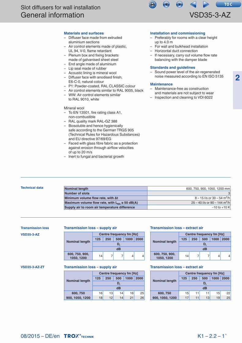
Transmission loss – supply air
Nominal length
Centre frequency fm [Hz]125 250 500 1000 2000
Dt
dB600, 750, 900,
1050, 1200 14 7 7 4 4
Transmission loss – supply air
Nominal length
Centre frequency fm [Hz]125 250 500 1000 2000
Dt
dB600, 750 16 13 14 16 25
900, 1050, 1200 18 12 14 21 26
Transmission loss – extract air
Nominal length
Centre frequency fm [Hz]125 250 500 1000 2000
Dt
dB600, 750, 900,
1050, 1200 14 7 7 4 4
Transmission loss – extract air
Nominal length
Centre frequency fm [Hz]125 250 500 1000 2000
Dt
dB600, 750 15 11 11 15 22
900, 1050, 1200 17 11 13 19 25
Nominal length 600, 750, 900, 1050, 1200 mmNumber of slots 3Minimum volume flow rate, with Δt 8 – 15 l/s or 30 – 54 m³/hMaximum volume flow rate, with LWA ≅ 50 dB(A) 25 – 40 l/s or 90 – 144 m³/hSupply air to room air temperature difference –10 to +10 K
Slot diffusers for wall installationGeneral information VSD35-3-AZ
08/2015 – DE/en
2
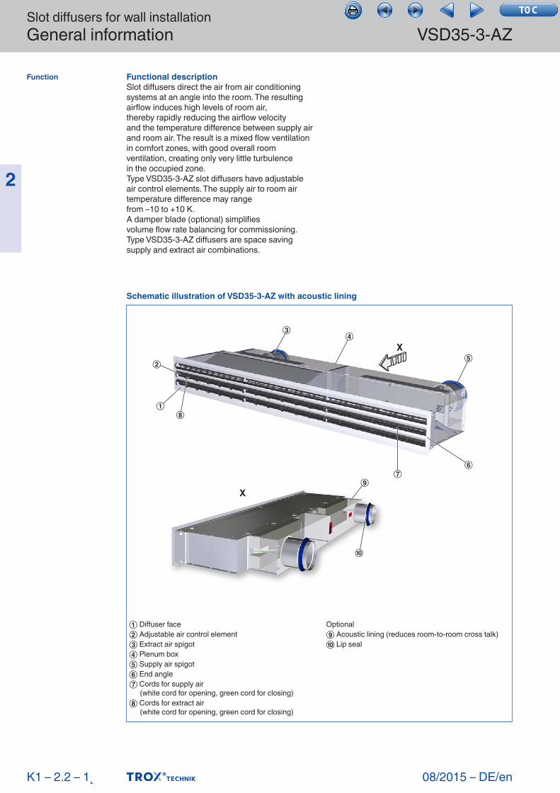
Functional descriptionSlot diffusers direct the air from air conditioning systems at an angle into the room. The resulting airflow induces high levels of room air,thereby rapidly reducing the airflow velocityand the temperature difference between supply air and room air. The result is a mixed flow ventilation in comfort zones, with good overall room ventilation, creating only very little turbulencein the occupied zone.Type VSD35-3-AZ slot diffusers have adjustable air control elements. The supply air to room air temperature difference may rangefrom –10 to +10 K.A damper blade (optional) simplifiesvolume flow rate balancing for commissioning.Type VSD35-3-AZ diffusers are space saving supply and extract air combinations.
K1 – 2.2 – 1˻
Function
Schematic illustration of VSD35-3-AZ with acoustic lining
X
X
④③
②
①
⑤
⑥⑦
⑩
⑨
⑧
① Diffuser face② Adjustable air control element③ Extract air spigot④ Plenum box⑤ Supply air spigot⑥ End angle⑦ Cords for supply air (white cord for opening, green cord for closing)⑧ Cords for extract air (white cord for opening, green cord for closing)
Optional⑨ Acoustic lining (reduces room-to-room cross talk)⑩ Lip seal
Slot diffusers for wall installationGeneral information
08/2015 – DE/en
VSD35-3-AZ
2
K1 – 2.2 – 1˼
Air patterns
Angled air discharge
Angled one-way air discharge and extract air
Slot diffusers for wall installationOrder code VSD35-3-AZ
08/2015 – DE/en
2
K1 – 2.2 – 1˽
VSD35-3-AZ
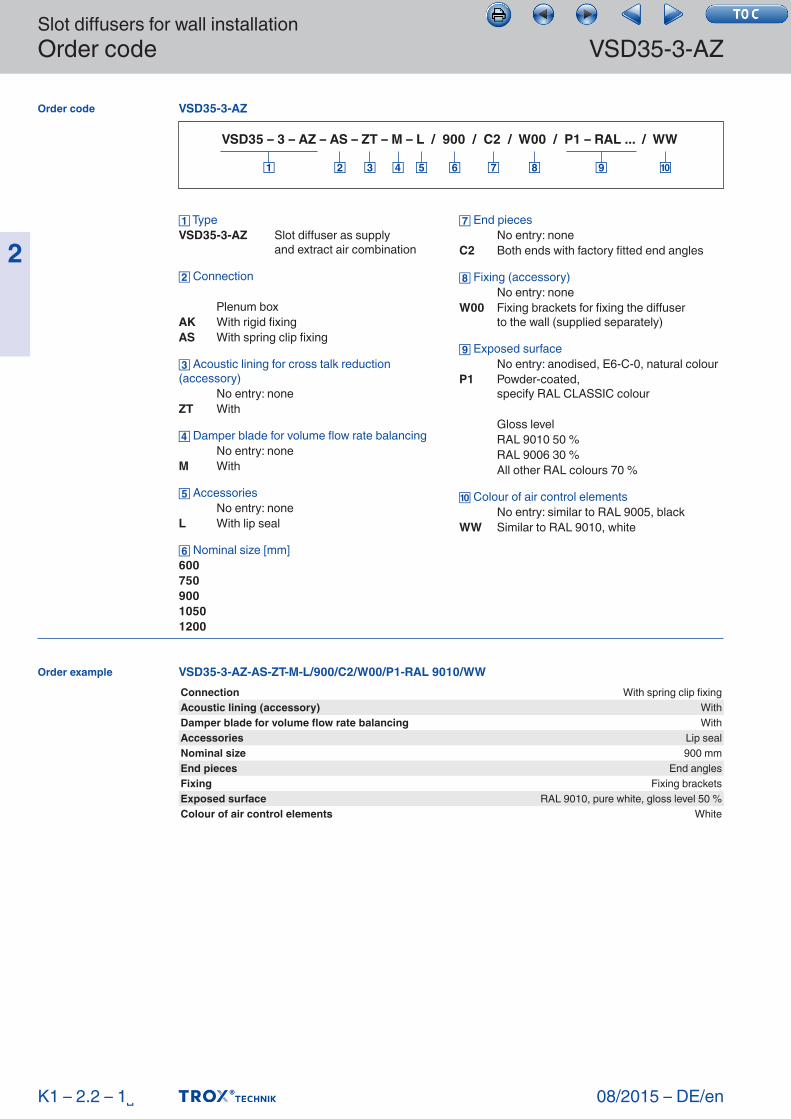
VSD35 – 3 – AZ – AS – ZT – M – L / 900 / C2 / W00 / P1 – RAL ... / WW
TypeVSD35-3-AZ Slot diffuser as supply and extract air combination
Connection
Plenum boxAK With rigid fixingAS With spring clip fixing
Acoustic lining for cross talk reduction (accessory) No entry: noneZT With
Damper blade for volume flow rate balancing No entry: noneM With
Accessories No entry: noneL With lip seal
Nominal size [mm]60075090010501200
End pieces No entry: noneC2 Both ends with factory fitted end angles
Fixing (accessory) No entry: noneW00 Fixing brackets for fixing the diffuser to the wall (supplied separately)
Exposed surface No entry: anodised, E6-C-0, natural colourP1 Powder-coated, specify RAL CLASSIC colour
Gloss level RAL 9010 50 % RAL 9006 30 % All other RAL colours 70 %
Colour of air control elements No entry: similar to RAL 9005, blackWW Similar to RAL 9010, white
Order code
Order example VSD35-3-AZ-AS-ZT-M-L/900/C2/W00/P1-RAL 9010/WWConnection With spring clip fixingAcoustic lining (accessory) WithDamper blade for volume flow rate balancing WithAccessories Lip sealNominal size 900 mmEnd pieces End anglesFixing Fixing bracketsExposed surface RAL 9010, pure white, gloss level 50 %Colour of air control elements White
Slot diffusers for wall installationQuick sizing
08/2015 – DE/en
VSD35-3-AZ
2
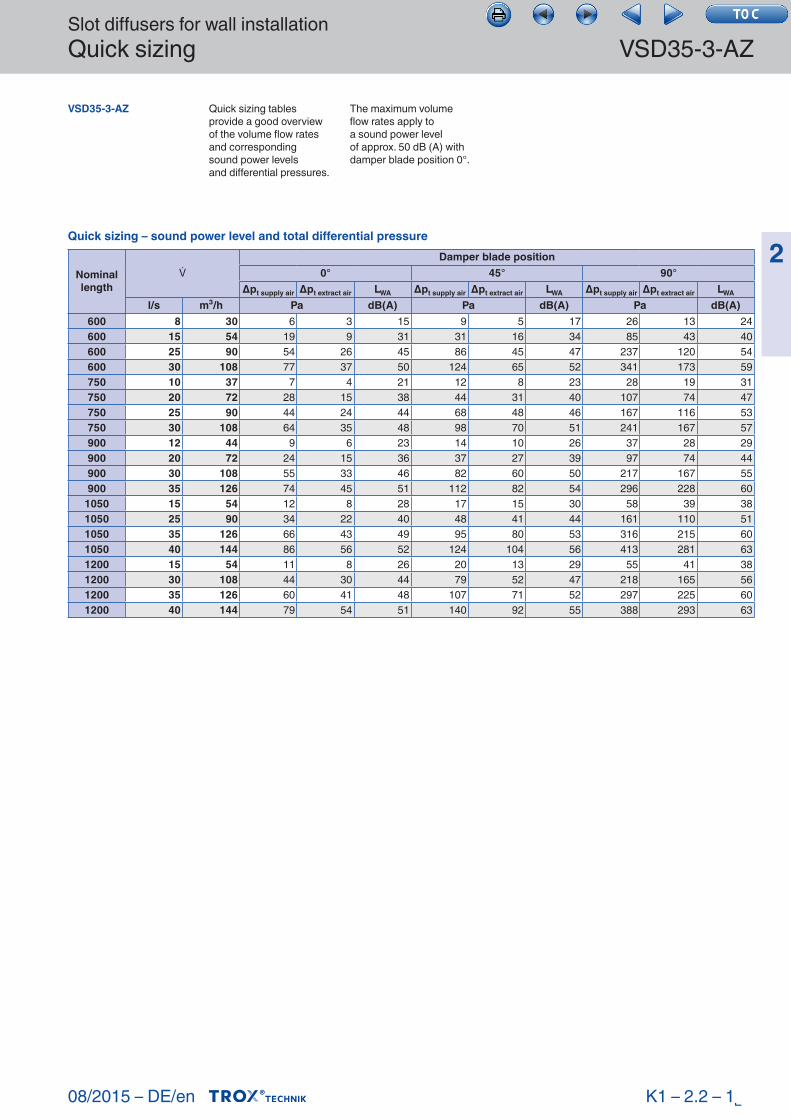
VSD35-3-AZ Quick sizing tables provide a good overview of the volume flow rates and correspondingsound power levelsand differential pressures.
The maximum volume flow rates apply toa sound power levelof approx. 50 dB (A) with damper blade position 0°.
K1 – 2.2 – 1˾
Quick sizing – sound power level and total differential pressure
Nominal length
Damper blade position
0° 45° 90°Δpt supply air Δpt extract air LWA Δpt supply air Δpt extract air LWA Δpt supply air Δpt extract air LWA
l/s m³/h Pa dB(A) Pa dB(A) Pa dB(A)600 8 30 6 3 15 9 5 17 26 13 24600 15 54 19 9 31 31 16 34 85 43 40600 25 90 54 26 45 86 45 47 237 120 54600 30 108 77 37 50 124 65 52 341 173 59750 10 37 7 4 21 12 8 23 28 19 31750 20 72 28 15 38 44 31 40 107 74 47750 25 90 44 24 44 68 48 46 167 116 53750 30 108 64 35 48 98 70 51 241 167 57900 12 44 9 6 23 14 10 26 37 28 29900 20 72 24 15 36 37 27 39 97 74 44900 30 108 55 33 46 82 60 50 217 167 55900 35 126 74 45 51 112 82 54 296 228 60
1050 15 54 12 8 28 17 15 30 58 39 381050 25 90 34 22 40 48 41 44 161 110 511050 35 126 66 43 49 95 80 53 316 215 601050 40 144 86 56 52 124 104 56 413 281 631200 15 54 11 8 26 20 13 29 55 41 381200 30 108 44 30 44 79 52 47 218 165 561200 35 126 60 41 48 107 71 52 297 225 601200 40 144 79 54 51 140 92 55 388 293 63
Slot diffusers for wall installationQuick sizing VSD35-3-AZ
08/2015 – DE/en
2
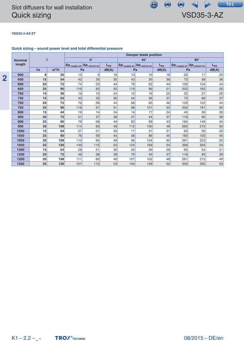
VSD35-3-AZ-ZT
K1 – 2.2 – ˷˵
Quick sizing – sound power level and total differential pressure
Nominal length
Damper blade position
0° 45° 90°Δpt supply air Δpt extract air LWA Δpt supply air Δpt extract air LWA Δpt supply air Δpt extract air LWA
l/s m³/h Pa dB(A) Pa dB(A) Pa dB(A)600 8 30 13 9 18 13 10 18 22 17 20600 15 54 42 30 35 43 35 36 73 58 36600 20 72 74 53 44 76 62 44 130 104 44600 25 90 116 83 50 119 96 51 203 162 50750 10 36 19 15 24 12 16 25 32 31 26750 15 54 43 33 36 44 36 37 73 69 37750 20 72 76 58 44 68 65 46 129 122 44750 25 90 118 91 51 98 101 52 202 191 50900 12 44 19 14 24 14 17 24 45 36 26900 20 72 51 37 38 37 44 37 118 95 39900 25 90 79 58 44 82 69 43 184 149 45900 30 108 114 83 49 112 100 48 265 215 50
1050 15 54 27 21 30 17 31 31 65 56 321050 25 90 76 59 44 48 86 45 182 155 451050 30 108 110 84 49 95 124 50 261 223 501050 35 126 149 115 53 124 169 54 356 304 541200 15 54 28 21 30 20 26 29 65 54 311200 20 72 49 38 38 79 45 37 116 95 391200 30 108 111 85 49 107 102 48 261 215 491200 35 126 151 115 53 140 139 52 355 292 53
Slot diffusers for wall installationDimensions and weight
08/2015 – DE/en
VSD35-3-AZ
2
K1 – 2.2 – ˷˶
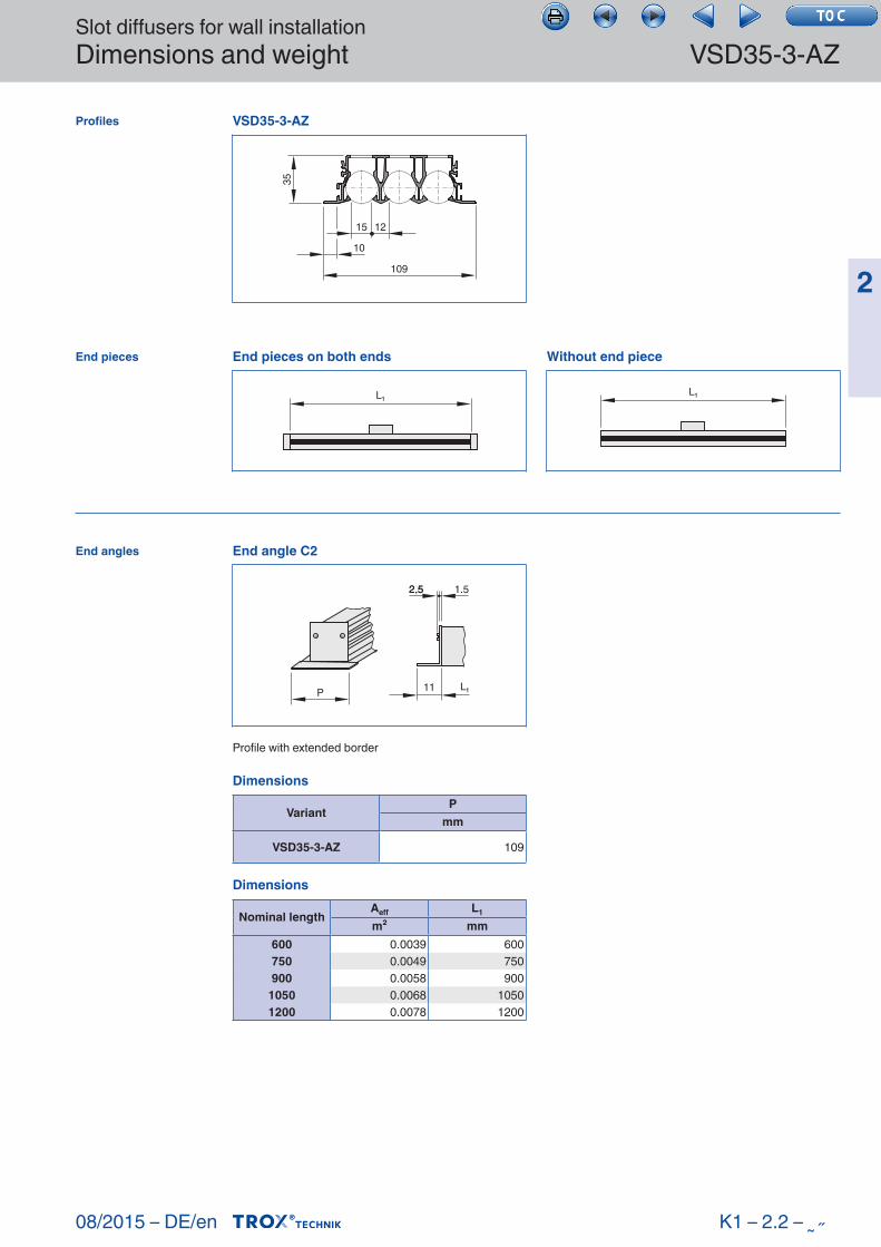
Profiles
End pieces
End angles
Dimensions
VariantP
mm
VSD35- 3-AZ 109
Dimensions
Nominal lengthAeff L1
m² mm600 0.0039 600750 0.0049 750900 0.0058 900
1050 0.0068 10501200 0.0078 1200
Profile with extended border
VSD35-3-AZ
15
10
109
12
35
End angle C2
P L₁11
2,52.5 1.5
End pieces on both ends
L₁
Without end piece
L₁
Slot diffusers for wall installationDimensions and weight VSD35-3-AZ
08/2015 – DE/en
2
K1 – 2.2 – ˷˷
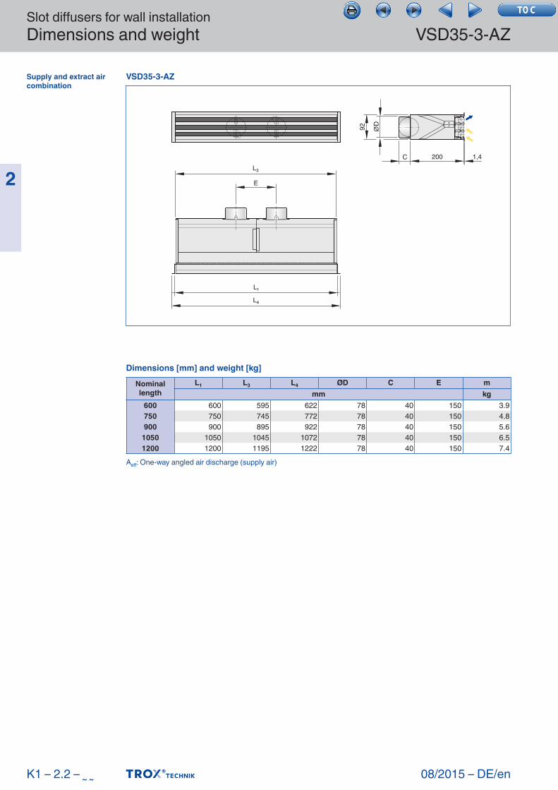
Supply and extract air combination
Dimensions [mm] and weight [kg]
Nominal length
L1 L3 L4 ØD C E mmm kg
600 600 595 622 78 40 150 3.9750 750 745 772 78 40 150 4.8900 900 895 922 78 40 150 5.6
1050 1050 1045 1072 78 40 150 6.51200 1200 1195 1222 78 40 150 7.4
Aeff: One-way angled air discharge (supply air)
VSD35-3-AZ
E
C 200 1,4
92 ∅D
L₃
L₁
L₄
Slot diffusers for wall installationDimensions and weight
08/2015 – DE/en
VSD35-3-AZ
2
K1 – 2.2 – ˷˸
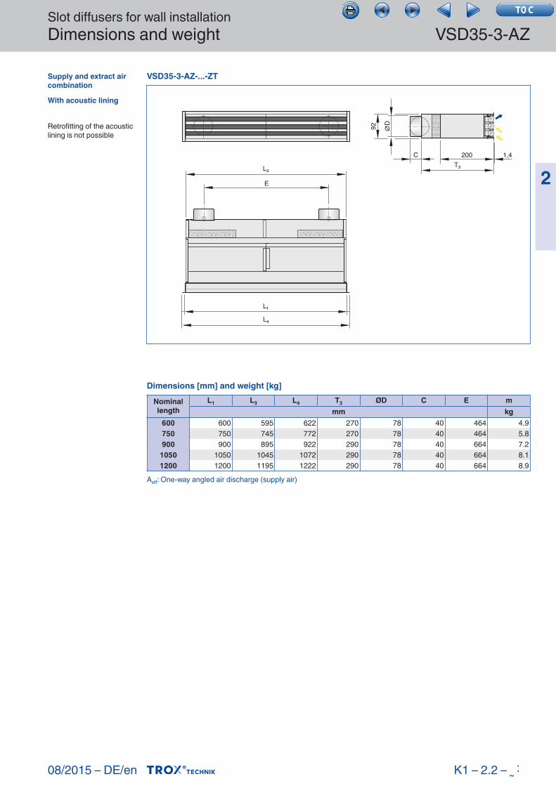
Supply and extract air combination
With acoustic lining
Retrofitting of the acoustic lining is not possible
Dimensions [mm] and weight [kg]
Nominal length
L1 L3 L4 T3 ØD C E mmm kg
600 600 595 622 270 78 40 464 4.9750 750 745 772 270 78 40 464 5.8900 900 895 922 290 78 40 664 7.2
1050 1050 1045 1072 290 78 40 664 8.11200 1200 1195 1222 290 78 40 664 8.9
Aeff: One-way angled air discharge (supply air)
VSD35-3-AZ-...-ZT
L₁
L₄
C 200 1,4T₃
92 ∅D
E
L₃
Slot diffusers for wall installationDimensions and weight VSD35-3-AZ
08/2015 – DE/en
2
K1 – 2.2 – ˷˹
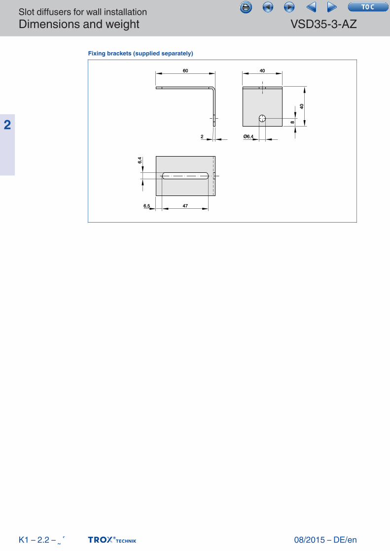
Fixing brackets (supplied separately)
60
476,5
6,4
40
8
40
Ø6,42
60
476.5
6.4
40
8
40
Ø6.42
Slot diffusers for wall installationInstallation details
08/2015 – DE/en
VSD35-3-AZ
2
K1 – 2.2 – ˷˺
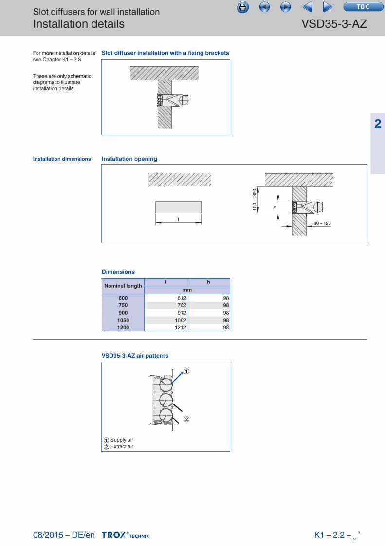
For more installation details see Chapter K1 – 2.3
These are only schematic diagrams to illustrate installation details.
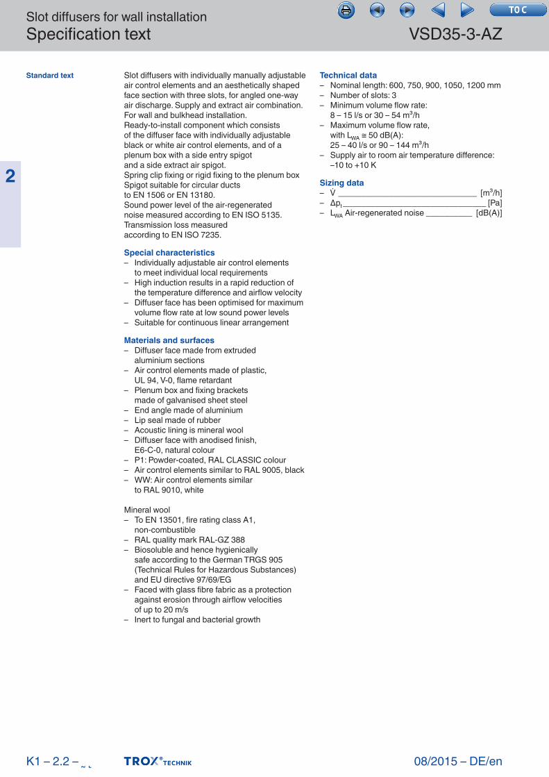
Installation dimensions
Dimensions
Nominal lengthl h
mm600 612 98750 762 98900 912 98
1050 1062 981200 1212 98
Slot diffuser installation with a fixing brackets
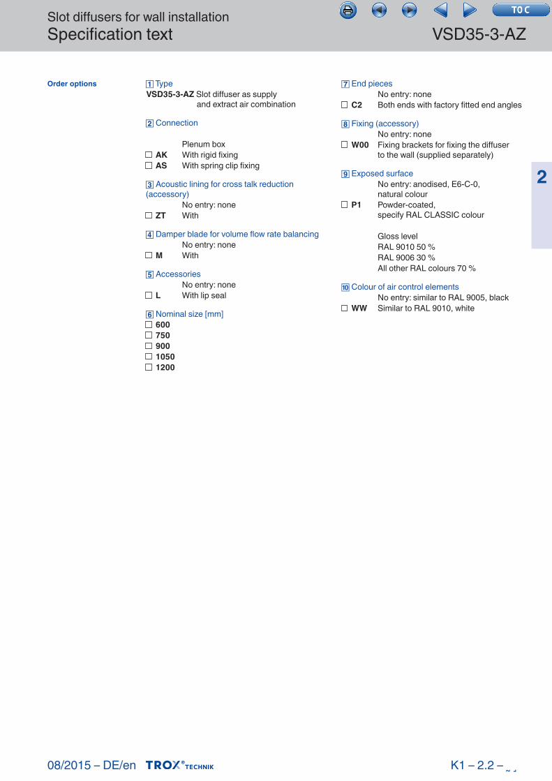
VSD35-3-AZ air patterns
①
②
① Supply air② Extract air
Installation opening
l
h100
– 3
00
80 – 120
Slot diffusers for wall installationSpecification text VSD35-3-AZ
08/2015 – DE/en
2
Slot diffusers with individually manually adjustable air control elements and an aesthetically shaped face section with three slots, for angled one-way air discharge. Supply and extract air combination. For wall and bulkhead installation.Ready-to-install component which consistsof the diffuser face with individually adjustable black or white air control elements, and of a plenum box with a side entry spigotand a side extract air spigot.Spring clip fixing or rigid fixing to the plenum boxSpigot suitable for circular ductsto EN 1506 or EN 13180.Sound power level of the air-regeneratednoise measured according to EN ISO 5135.Transmission loss measuredaccording to EN ISO 7235.
Special characteristics– Individually adjustable air control elements to meet individual local requirements– High induction results in a rapid reduction of
the temperature difference and airflow velocity– Diffuser face has been optimised for maximum
volume flow rate at low sound power levels– Suitable for continuous linear arrangement
Materials and surfaces– Diffuser face made from extruded aluminium sections– Air control elements made of plastic, UL 94, V- 0, flame retardant– Plenum box and fixing brackets made of galvanised sheet steel– End angle made of aluminium– Lip seal made of rubber– Acoustic lining is mineral wool– Diffuser face with anodised finish, E6-C-0, natural colour– P1: Powder-coated, RAL CLASSIC colour– Air control elements similar to RAL 9005, black– WW: Air control elements similar to RAL 9010, white
Mineral wool– To EN 13501, fire rating class A1, non- combustible– RAL quality mark RAL-GZ 388– Biosoluble and hence hygienically safe according to the German TRGS 905
(Technical Rules for Hazardous Substances) and EU directive 97/69/EG
– Faced with glass fibre fabric as a protection against erosion through airflow velocities
of up to 20 m/s– Inert to fungal and bacterial growth
Technical data– Nominal length: 600, 750, 900, 1050, 1200 mm– Number of slots: 3– Minimum volume flow rate: 8 – 15 l/s or 30 – 54 m³/h– Maximum volume flow rate, with LWA ≅ 50 dB(A): 25 – 40 l/s or 90 – 144 m³/h– Supply air to room air temperature difference:
–10 to +10 K
Sizing data– ______________________________ [m³/h]– Δpt _______________________________ [Pa]– LWA Air-regenerated noise __________ [dB(A)]
Standard text
K1 – 2.2 – ˷˻
Slot diffusers for wall installationSpecification text
08/2015 – DE/en
VSD35-3-AZ
2
TypeVSD35-3-AZ Slot diffuser as supply and extract air combination
Connection
Plenum box
Acoustic lining for cross talk reduction (accessory) No entry: none
Damper blade for volume flow rate balancing No entry: none
Accessories No entry: none
Nominal size [mm]
AK With rigid fixingAS With spring clip fixing
ZT With
M With
L With lip seal
60075090010501200
End pieces No entry: none
Fixing (accessory) No entry: none
Exposed surface No entry: anodised, E6-C-0, natural colour
Gloss level RAL 9010 50 % RAL 9006 30 % All other RAL colours 70 %
Colour of air control elements No entry: similar to RAL 9005, black
C2 Both ends with factory fitted end angles
W00 Fixing brackets for fixing the diffuser to the wall (supplied separately)
P1 Powder-coated, specify RAL CLASSIC colour
WW Similar to RAL 9010, white
K1 – 2.2 – ˷˼
Order options
08/2015 – DE/en
Slot diffusersBasic informationand nomenclature
2
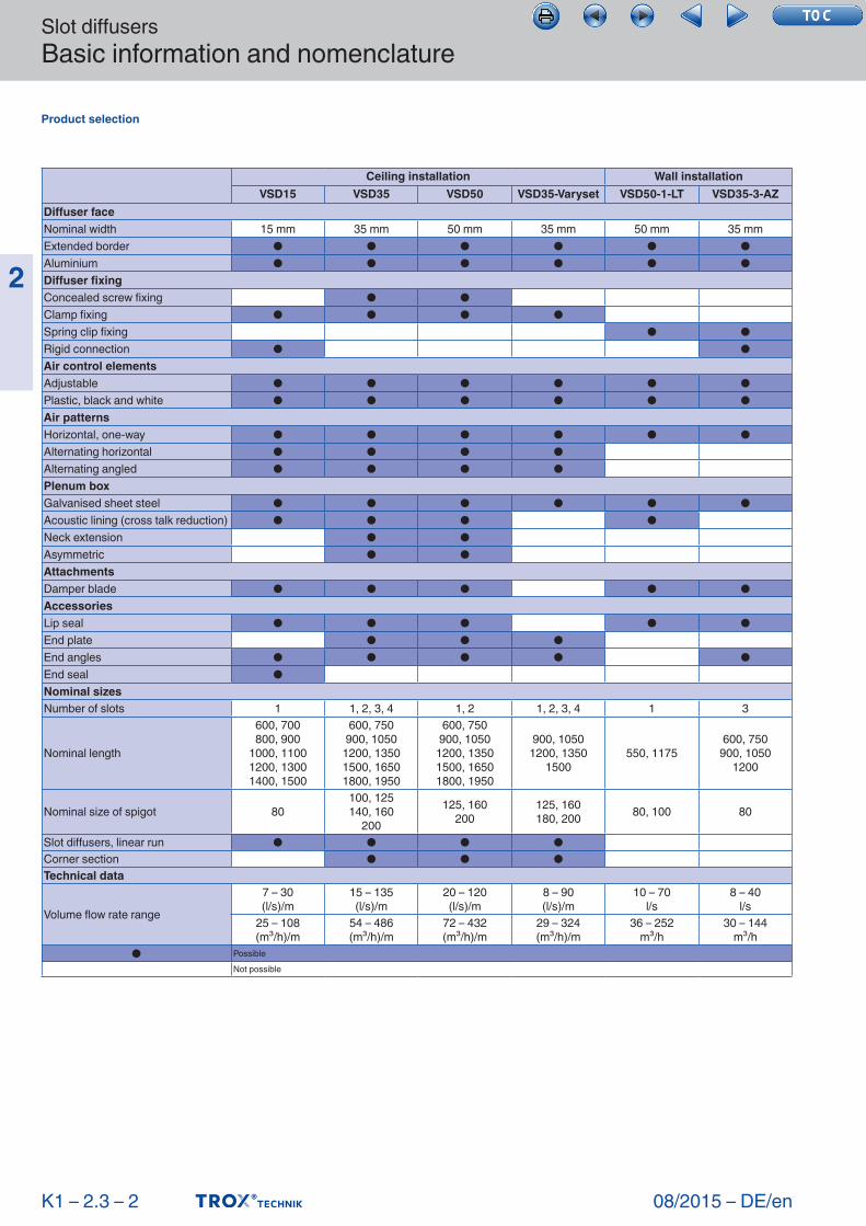
■ Product selection ■ Principal dimensions ■ Nomenclature ■ Sizing and sizing example ■ Installation information ■ Commissioning
2.3 –
X XBasic information and nomenclaturetestregistrierung
K1 – 2.3 – 1
Slot diffusers
Slot diffusersBasic information and nomenclature
08/2015 – DE/en
2
Product selection
K1 – 2.3 – 2
Ceiling installation Wall installationVSD15 VSD35 VSD50 VSD35-Varyset VSD50-1-LT VSD35-3-AZ
Diffuser faceNominal width 15 mm 35 mm 50 mm 35 mm 50 mm 35 mmExtended border ● ● ● ● ● ● Aluminium ● ● ● ● ● ●Diffuser fixingConcealed screw fixing ● ●Clamp fixing ● ● ● ●Spring clip fixing ● ●Rigid connection ● ● Air control elementsAdjustable ● ● ● ● ● ● Plastic, black and white ● ● ● ● ● ●Air patterns Horizontal, one-way ● ● ● ● ● ● Alternating horizontal ● ● ● ●Alternating angled ● ● ● ● Plenum box Galvanised sheet steel ● ● ● ● ● ● Acoustic lining (cross talk reduction) ● ● ● ● Neck extension ● ●Asymmetric ● ● AttachmentsDamper blade ● ● ● ● ● AccessoriesLip seal ● ● ● ● ● End plate ● ● ●End angles ● ● ● ● ●End seal ● Nominal sizesNumber of slots 1 1, 2, 3, 4 1, 2 1, 2, 3, 4 1 3
Nominal length
600, 700 800, 900
1000, 1100 1200, 1300 1400, 1500
600, 750 900, 1050
1200, 1350 1500, 1650 1800, 1950
600, 750 900, 1050
1200, 1350 1500, 1650 1800, 1950
900, 1050 1200, 1350
1500550, 1175
600, 750 900, 1050
1200
Nominal size of spigot 80100, 125 140, 160
200
125, 160 200
125, 160 180, 200 80, 100 80
Slot diffusers, linear run ● ● ● ● Corner section ● ● ●Technical data
Volume flow rate range
7 – 30 (l/s)/m
15 – 135 (l/s)/m
20 – 120 (l/s)/m
8 – 90 (l/s)/m
10 – 70 l/s
8 – 40 l/s
25 – 108 (m³/h)/m
54 – 486 (m³/h)/m
72 – 432 (m³/h)/m
29 – 324 (m³/h)/m
36 – 252 m³/h
30 – 144 m³/h
● PossibleNot possible
Slot diffusersBasic information and nomenclature
08/2015 – DE/en
2
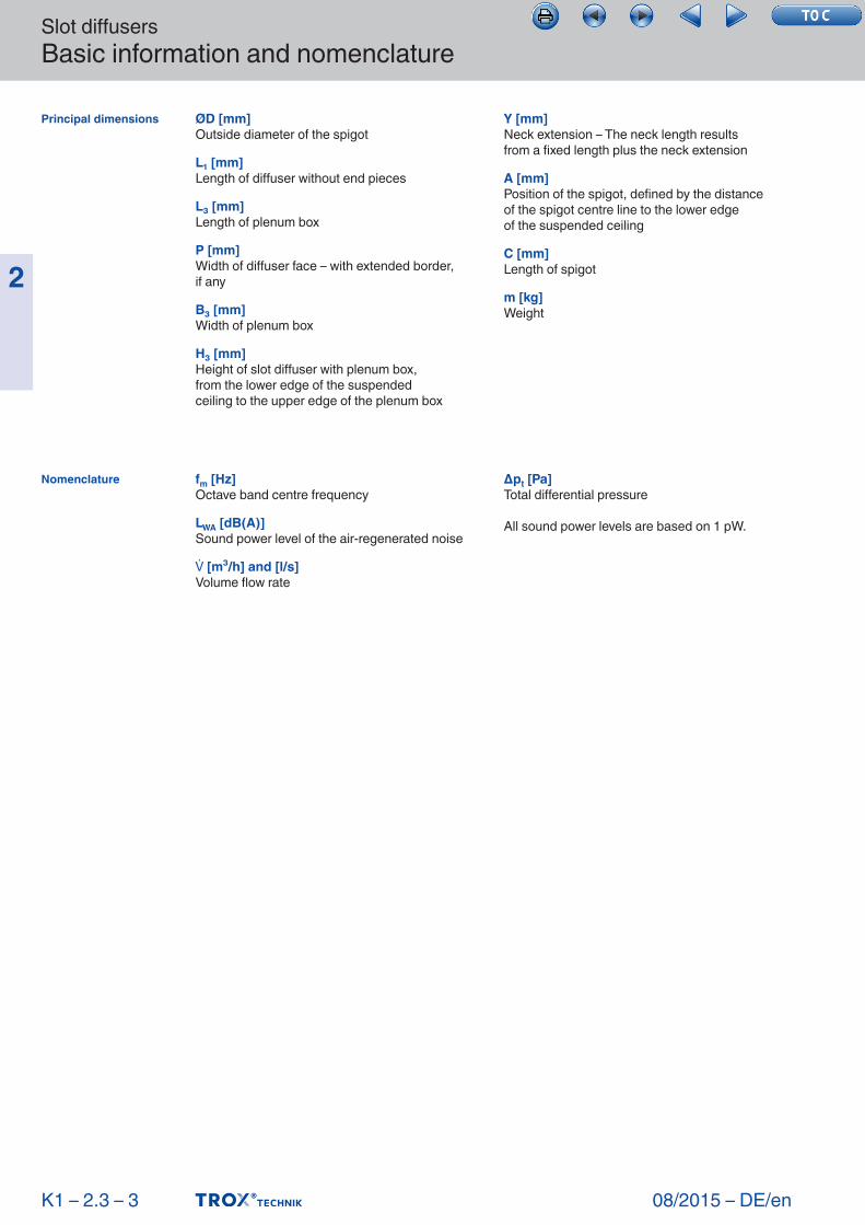
ØD [mm]Outside diameter of the spigot
L₁ [mm]Length of diffuser without end pieces
L₃ [mm]Length of plenum box
P [mm]Width of diffuser face – with extended border,if any
B₃ [mm]Width of plenum box
H₃ [mm]Height of slot diffuser with plenum box,from the lower edge of the suspendedceiling to the upper edge of the plenum box
Y [mm]Neck extension – The neck length resultsfrom a fixed length plus the neck extension
A [mm]Position of the spigot, defined by the distance of the spigot centre line to the lower edgeof the suspended ceiling
C [mm]Length of spigot
m [kg]Weight
fm [Hz]Octave band centre frequency
LWA [dB(A)]Sound power level of the air-regenerated noise
[m³/h] and [l/s]Volume flow rate
Δpt [Pa]Total differential pressure
All sound power levels are based on 1 pW.
K1 – 2.3 – 3
Principal dimensions
Nomenclature
Slot diffusersBasic information and nomenclature
08/2015 – DE/en
2
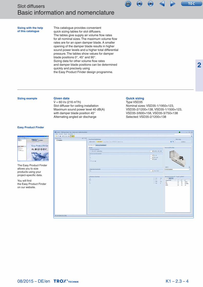
This catalogue provides convenientquick sizing tables for slot diffusers.The tables give supply air volume flow ratesfor all nominal sizes. The maximum volume flow rates are for an open damper blade. A smaller opening of the damper blade results in higher sound power levels and a higher total differential pressure. The tables show values for damper blade positions 0°, 45° and 90°.Sizing data for other volume flow ratesand damper blade positions can be determined quickly and precisely usingthe Easy Product Finder design programme.
Given data = 60 l/s (216 m3/h)Slot diffuser for ceiling installationMaximum sound power level 40 dB(A)with damper blade position 45°Alternating angled air discharge
Quick sizingType VSD35Nominal sizes: VSD35-1/1950×123,VSD35-2/ 1200×138, VSD35-1/1500×123,VSD35-3/ 600×158, VSD35-3/750×138Selected: VSD35-2/1200×138
Sizing example
K1 – 2.3 – 4
Sizing with the helpof this catalogue
Easy Product Finder
The Easy Product Finder allows you to size products using your project-specific data.
You will findthe Easy Product Finder on our website.
Slot diffusersBasic information and nomenclature
08/2015 – DE/en
2
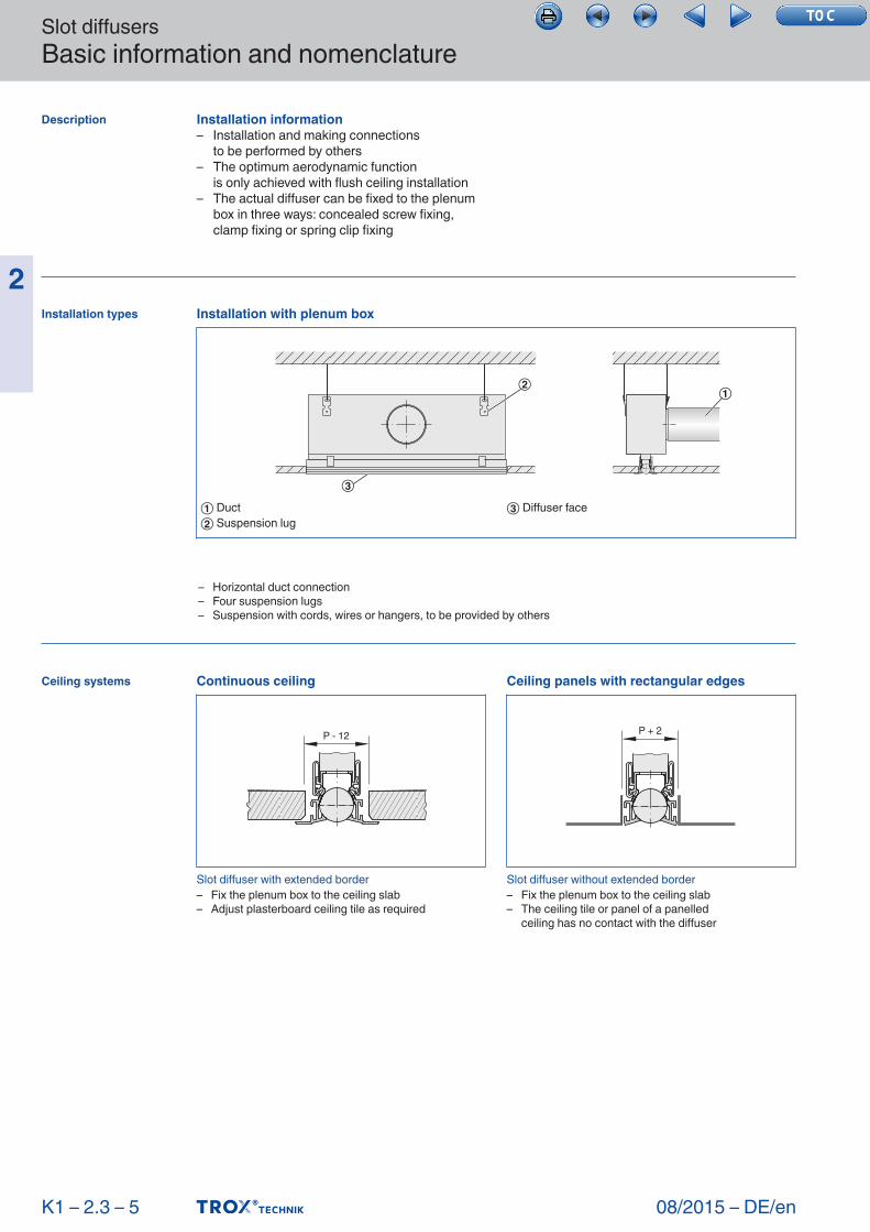
Installation information– Installation and making connections to be performed by others– The optimum aerodynamic function is only achieved with flush ceiling installation– The actual diffuser can be fixed to the plenum
box in three ways: concealed screw fixing, clamp fixing or spring clip fixing
K1 – 2.3 – 5
Description
Installation types
Ceiling systems
– Horizontal duct connection– Four suspension lugs– Suspension with cords, wires or hangers, to be provided by others
Slot diffuser with extended border– Fix the plenum box to the ceiling slab– Adjust plasterboard ceiling tile as required
Slot diffuser without extended border– Fix the plenum box to the ceiling slab– The ceiling tile or panel of a panelled ceiling has no contact with the diffuser
Continuous ceiling
P - 12
Ceiling panels with rectangular edges
P + 2
Installation with plenum box
①②
③
① Duct② Suspension lug
③ Diffuser face
Slot diffusersBasic information and nomenclature
08/2015 – DE/en
2
K1 – 2.3 – 6
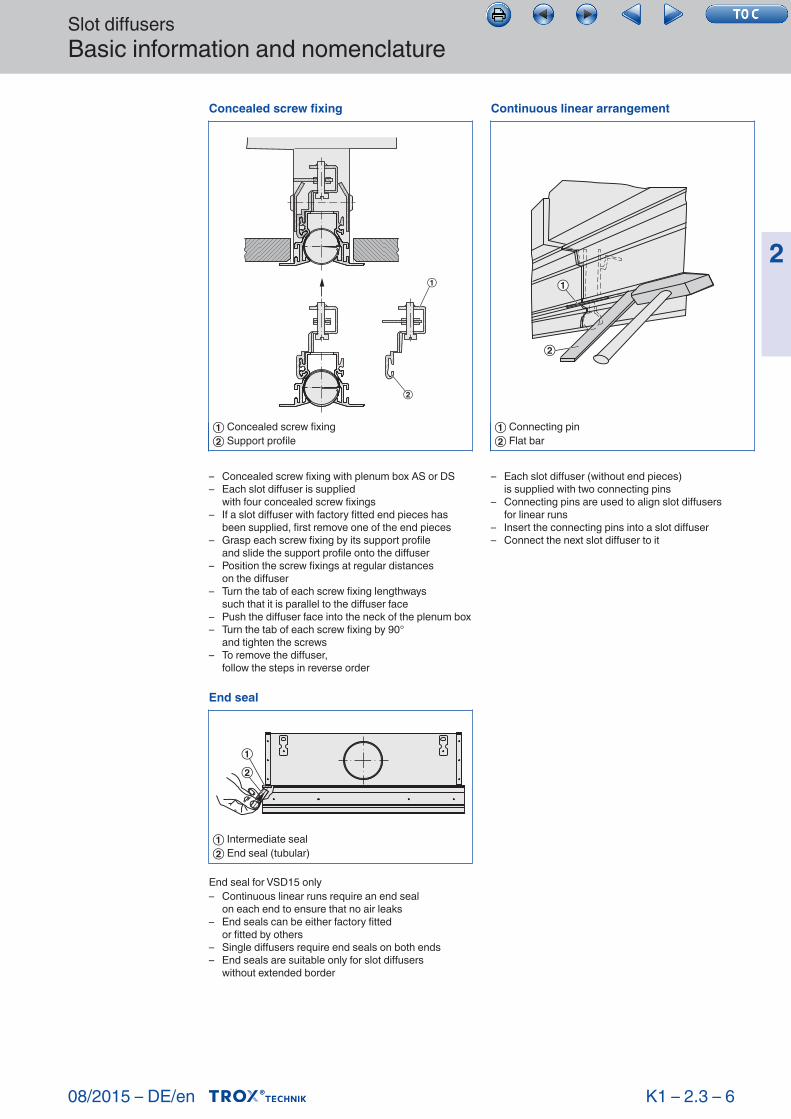
End seal for VSD15 only– Continuous linear runs require an end seal on each end to ensure that no air leaks– End seals can be either factory fitted or fitted by others– Single diffusers require end seals on both ends– End seals are suitable only for slot diffusers without extended border
– Concealed screw fixing with plenum box AS or DS– Each slot diffuser is supplied with four concealed screw fixings– If a slot diffuser with factory fitted end pieces has
been supplied, first remove one of the end pieces– Grasp each screw fixing by its support profile and slide the support profile onto the diffuser– Position the screw fixings at regular distances on the diffuser– Turn the tab of each screw fixing lengthways such that it is parallel to the diffuser face– Push the diffuser face into the neck of the plenum box– Turn the tab of each screw fixing by 90° and tighten the screws– To remove the diffuser, follow the steps in reverse order
– Each slot diffuser (without end pieces) is supplied with two connecting pins– Connecting pins are used to align slot diffusers for linear runs– Insert the connecting pins into a slot diffuser– Connect the next slot diffuser to it
End seal
②①
① Intermediate seal② End seal (tubular)
Concealed screw fixing
① Concealed screw fixing② Support profile
①
②
Continuous linear arrangement
①
②
① Connecting pin② Flat bar
Slot diffusersBasic information and nomenclature
08/2015 – DE/en
2
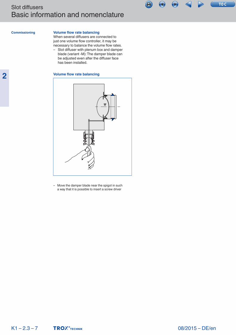
Volume flow rate balancing When several diffusers are connected tojust one volume flow controller, it may be necessary to balance the volume flow rates.– Slot diffuser with plenum box and damper
blade (variant -M): The damper blade can be adjusted even after the diffuser face has been installed.
K1 – 2.3 – 7
Commissioning
– Move the damper blade near the spigot in such a way that it is possible to insert a screw driver
Volume flow rate balancing