sls at the paul scherrer institute (psi), villigen,...
TRANSCRIPT
Orbit Stability at the SLS
IWBS2004
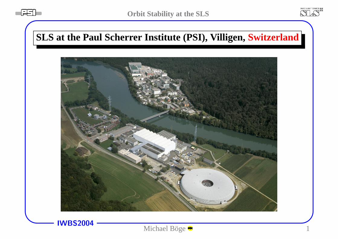
SLS at the Paul Scherrer Institute (PSI), Villigen,Switzerland
Michael Boge 1
Orbit Stability at the SLS
IWBS2004
Contents
• SLS Layout
• Booster & Storage Ring (SR)
– Lattice Calibration
– Stability∗ Requirements∗ Noise Sources∗ Short Term∗ BBA/Golden Orbit∗ Orbit Correction∗ Medium Term (“Top-up”)∗ Transition Slow→ Fast Orbit Feedback∗ Feed Forward, X-BPM & Bunch Pattern Feedback∗ Long Term
• Conclusions
Michael Boge 2
Orbit Stability at the SLS
IWBS2004
SLS Layout
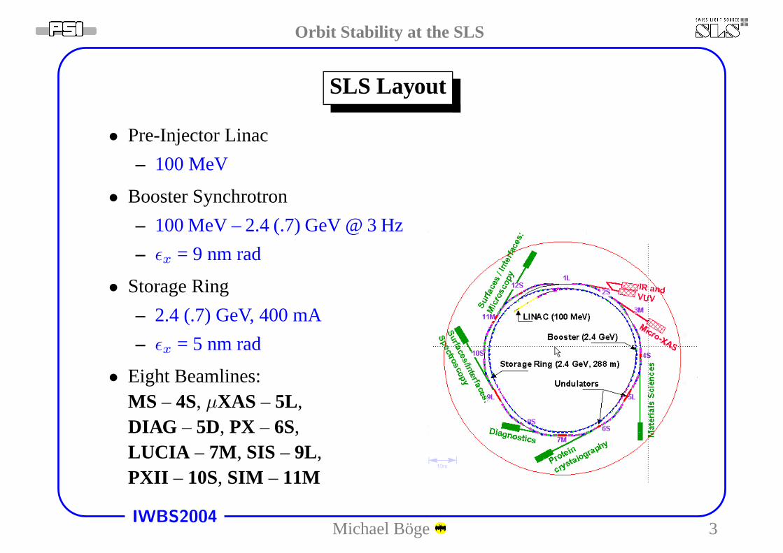
• Pre-Injector Linac
– 100 MeV
• Booster Synchrotron
– 100 MeV – 2.4 (.7) GeV @ 3 Hz
– ǫx = 9 nm rad
• Storage Ring
– 2.4 (.7) GeV, 400 mA
– ǫx = 5 nm rad
• Eight Beamlines:MS – 4S, µXAS – 5L,DIAG – 5D, PX – 6S,LUCIA – 7M, SIS – 9L,PXII – 10S, SIM – 11M
Michael Boge 3
Orbit Stability at the SLS
IWBS2004
Booster - Design
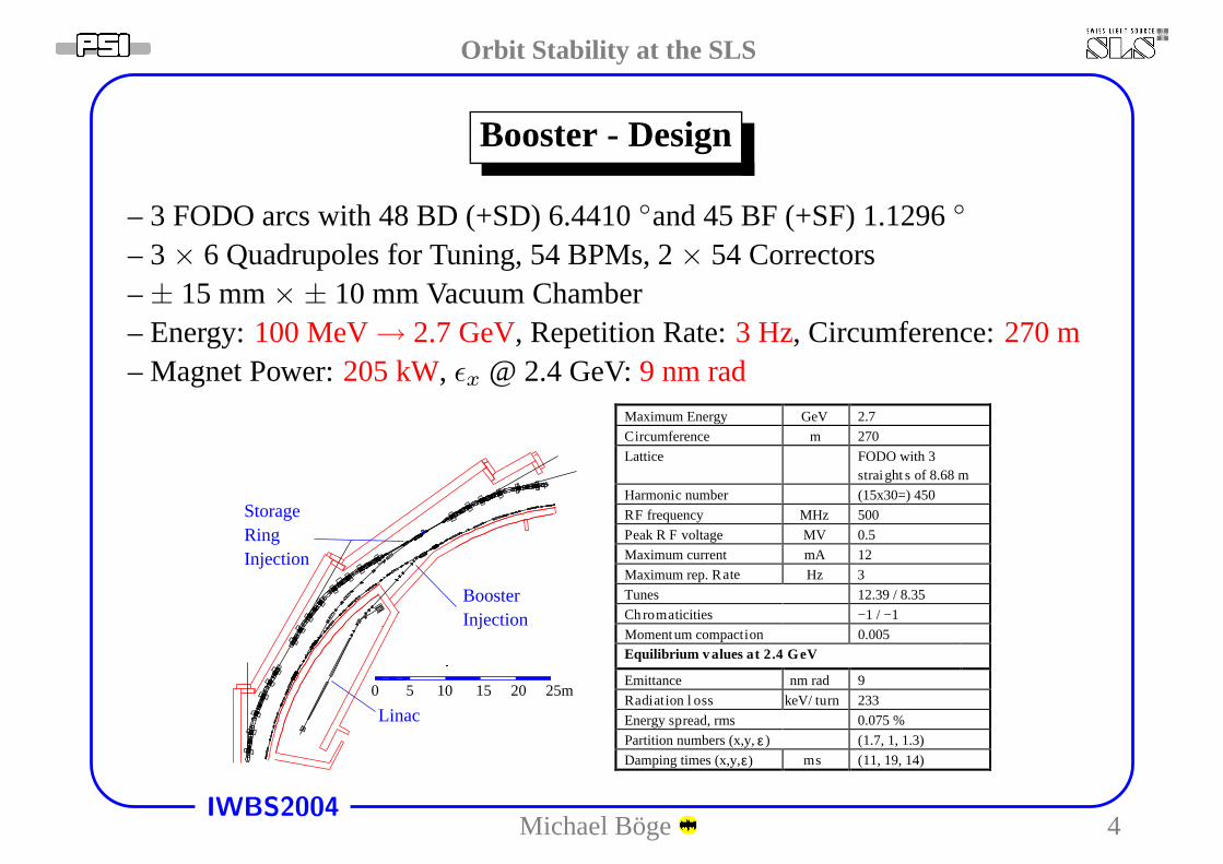
– 3 FODO arcs with 48 BD (+SD) 6.4410◦and 45 BF (+SF) 1.1296◦
– 3× 6 Quadrupoles for Tuning, 54 BPMs, 2× 54 Correctors–± 15 mm× ± 10 mm Vacuum Chamber– Energy:100 MeV→ 2.7 GeV, Repetition Rate:3 Hz, Circumference:270 m– Magnet Power:205 kW, ǫx @ 2.4 GeV:9 nm rad
Injection
StorageRing
Linac
BoosterInjection
0 5 10 15 20 25m
OTR
Maximum Energy GeV 2.7
Circumference m 270
Lattice FODO with 3straight s of 8.68 m
Harmonic number (15x30=) 450
RF frequency MHz 500
Peak R F voltage MV 0.5
Maximum current mA 12
Maximum rep. Rate Hz 3
Tunes 12.39 / 8.35
Chromaticities −1 / −1
Momentum compaction 0.005
pread, rms
t 2.4 GeVEquilibrium v
Emittance 9
Radiation l oss keV/ turn 233
Energy s 0.075 %
Partition numbers (x,y, (1.7, 1, 1.3)
Damping times (x,y, ms (11, 19, 14)
alues a
nm rad
ε )
ε)
Michael Boge 4
Orbit Stability at the SLS
IWBS2004
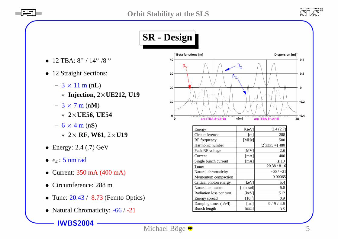
SR - Design
• 12 TBA: 8◦ / 14◦ /8 ◦
• 12 Straight Sections:
– 3 × 11 m(nL )
∗ Injection , 2×UE212, U19
– 3 × 7 m (nM )
∗ 2×UE56, UE54
– 6 × 4 m (nS)
∗ 2× RF, W61, 2×U19
• Energy: 2.4 (.7) GeV
• ǫx: 5 nm rad
• Current:350 mA (400 mA)
• Circumference: 288 m
• Tune:20.43/ 8.73(Femto Optics)
• Natural Chromaticity:-66 / -21
βyη
x
βx
0 48arc (TBA 8−14−8)arc (TBA 8−14−8) s[m]0
10
20
30
40
Beta functions [m]
−0.2
Dispersion [m]
−0.4
0.2
0.4
0
Energy [GeV]Circumference [m] 2
2.4 (2.7)88
RF frequency [MHz] 500Harmonic number (25x3x5 =) 480Peak RF voltage [MV] 2.6Current [mA] 400Single bunch current [mA] ≤ 10Tunes 20.38 / 8.16
Natural chromaticity −66 / −21
Momentum compaction 0.00065Critical photon energy [keV] 5.4Natural emittance [nm rad] 5.0Radiation loss per turn [keV] 512Energy spread [10−3] 0.9Damping times (h/v/l) [ms] 9 / 9 / 4.5Bunch length [mm] 3.5
Michael Boge 5
Orbit Stability at the SLS
IWBS2004
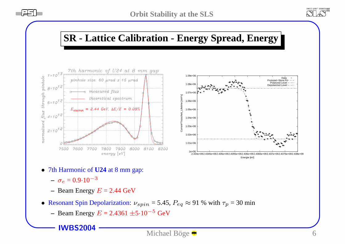
SR - Lattice Calibration - Energy Spread, Energy
1e+06
1.01e+06
1.02e+06
1.03e+06
1.04e+06
1.05e+06
1.06e+06
1.07e+06
1.08e+06
1.09e+06
2.434e+092.4345e+092.435e+092.4355e+092.436e+092.4365e+092.437e+092.4375e+092.438e+09
Cur
rent
*Tou
sche
k_Li
fetim
e [m
A*s
]
Energie [eV]
DataFroissart−Stora Fit
Polarized LevelDepolarized Level
• 7th Harmonic ofU24 at 8 mm gap:
– σe = 0.9·10−3
– Beam EnergyE = 2.44 GeV
• Resonant Spin Depolarization:νspin = 5.45,Peq ≈ 91 % withτp = 30 min
– Beam EnergyE = 2.4361±5·10−5 GeV
Michael Boge 6
Orbit Stability at the SLS
IWBS2004
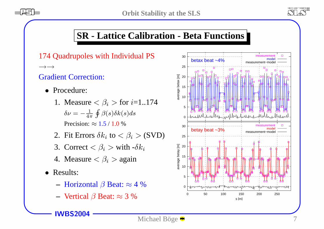
SR - Lattice Calibration - Beta Functions
174 Quadrupoles with Individual PS→→
Gradient Correction:
• Procedure:
1. Measure< βi > for i=1..174δν = − 1
4π
∮
β(s)δk(s)ds
Precision:≈ 1.5/ 1.0%
2. Fit Errorsδki to < βi > (SVD)
3. Correct< βi > with -δki
4. Measure< βi > again
• Results:
– Horizontalβ Beat:≈ 4 %
– Verticalβ Beat:≈ 3 %
0
0
5
5
10
10
15
15
20
20
25
25
30
30
0 50 100 150 200 250
aver
age
beta
x [m
]av
erag
e be
tay
[m]
s [m]
measurement
measurement
model
model
measurement−model
measurement−model
betax beat ~4%
betay beat ~3%
Michael Boge 7
Orbit Stability at the SLS
IWBS2004
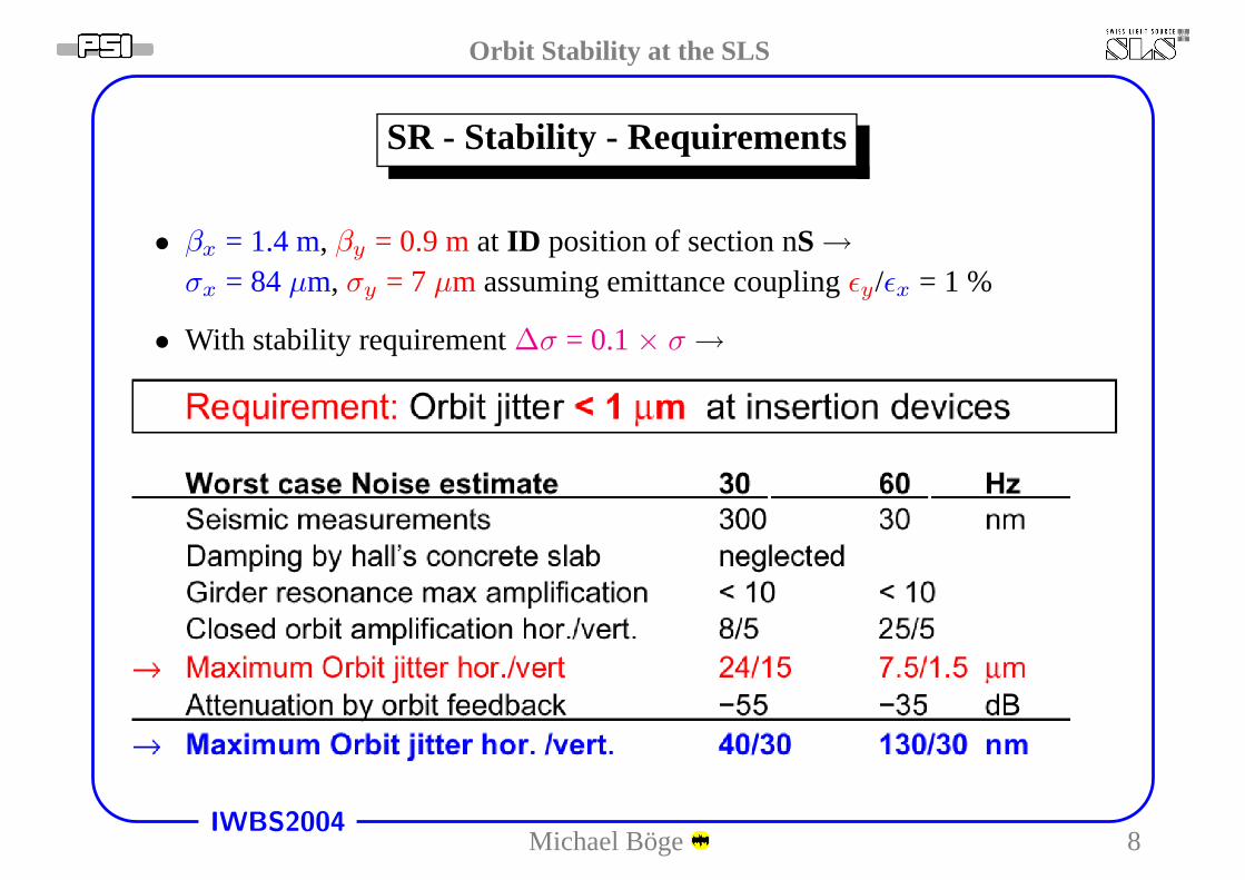
SR - Stability - Requirements
• βx = 1.4 m, βy = 0.9 mat ID position of section nS→
σx = 84µm, σy = 7 µm assuming emittance couplingǫy/ǫx = 1 %
• With stability requirement∆σ = 0.1× σ →
Michael Boge 8
Orbit Stability at the SLS
IWBS2004
SR - Stability - Noise Sources
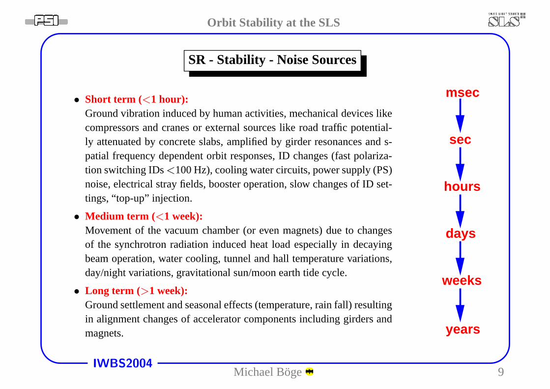
• Short term (<1 hour):Ground vibration induced by human activities, mechanical devices likecompressors and cranes or external sources like road trafficpotential-ly attenuated by concrete slabs, amplified by girder resonances and s-patial frequency dependent orbit responses, ID changes (fast polariza-tion switching IDs<100 Hz), cooling water circuits, power supply (PS)noise, electrical stray fields, booster operation, slow changes of ID set-tings, “top-up” injection.
• Medium term (<1 week):Movement of the vacuum chamber (or even magnets) due to changesof the synchrotron radiation induced heat load especially in decayingbeam operation, water cooling, tunnel and hall temperaturevariations,day/night variations, gravitational sun/moon earth tide cycle.
• Long term (>1 week):Ground settlement and seasonal effects (temperature, rainfall) resultingin alignment changes of accelerator components including girders andmagnets.
msec
sec
hours
days
weeks
years
Michael Boge 9
Orbit Stability at the SLS
IWBS2004
SR - Stability - Short Term
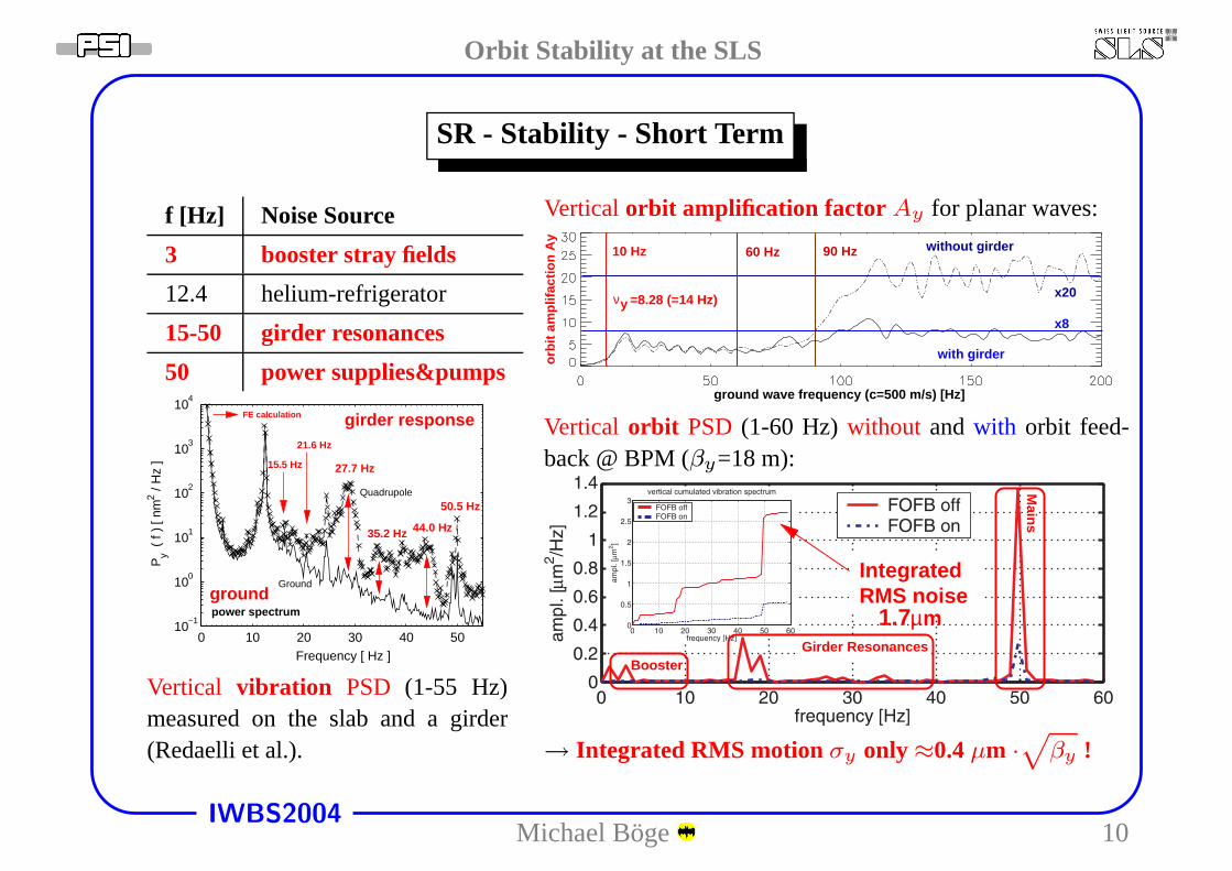
f [Hz] Noise Source
3 booster stray fields
12.4 helium-refrigerator
15-50 girder resonances
50 power supplies&pumps
0 10 20 30 40 5010
−1
100
101
102
103
104
27.7 Hz
35.2 Hz
50.5 Hz
15.5 Hz
21.6 Hz
groundpower spectrum
FE calculation girder response
44.0 Hz
Frequency [ Hz ]
Py
( f
) [ n
m2 /
Hz
]
Ground
Quadrupole
Vertical vibration PSD (1-55 Hz)measured on the slab and a girder(Redaelli et al.).
Vertical orbit amplification factor Ay for planar waves:
orbi
t am
plifa
ctio
n A
y 10 Hz without girder
with girder
60 Hz
x20
x8
ground wave frequency (c=500 m/s) [Hz]
90 Hz
νy =8.28 (=14 Hz)
Vertical orbit PSD(1-60 Hz) without and with orbit feed-back @ BPM (βy=18 m):
µm1.7
Booster
Mains
Girder Resonances
IntegratedRMS noise
→ Integrated RMS motion σy only ≈0.4µm ·√
βy !
Michael Boge 10
Orbit Stability at the SLS
IWBS2004
SR - BPM/Corrector Layout
sector
8 814
Quadrupole
Sextupole
Dipole
Horizontal / Vertical Correctors
BPMs
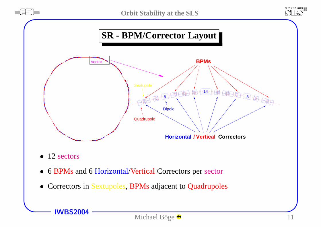
• 12sectors
• 6 BPMsand 6Horizontal/Vertical Correctors persector
• Correctors inSextupoles, BPMsadjacent toQuadrupoles
Michael Boge 11
Orbit Stability at the SLS
IWBS2004
SR - Stability - BBA/Golden Orbit
phase [rad/2pi]
2 4 6 8
posy [mm]
−0.5
0
0.5b
pm
01
lbb
pm
01
leb
pm
01
ldb
pm
01
sdb
pm
01
seb
pm
01
sb
bp
m0
2sb
bp
m0
2se
bp
m0
2sd
bp
m0
2m
db
pm
02
me
bp
m0
2m
b
bp
m0
3m
bb
pm
03
me
bp
m0
3m
db
pm
03
sdb
pm
03
seb
pm
03
sb
bp
m0
4sb
bp
m0
4se
bp
m0
4sd
bp
m0
4ld
bp
m0
4le
bp
m0
4lb
bp
m0
5lb
bp
m0
5le
bp
m0
5ld
bp
m0
5sd
bp
m0
5se
bp
m0
5sb
bp
m0
6sb
bp
m0
6se
bp
m0
6sd
bp
m0
6m
db
pm
06
me
bp
m0
6m
b
bp
m0
7m
bb
pm
07
me
bp
m0
7m
db
pm
07
sdb
pm
07
seb
pm
07
sb
bp
m0
8sb
bp
m0
8se
bp
m0
8sd
bp
m0
8ld
bp
m0
8le
bp
m0
8lb
bp
m0
9lb
bp
m0
9le
bp
m0
9ld
bp
m0
9sd
bp
m0
9se
bp
m0
9sb
bp
m1
0sb
bp
m1
0se
bp
m1
0sd
bp
m1
0m
db
pm
10
me
bp
m1
0m
b
bp
m1
1m
bb
pm
11
me
bp
m1
1m
db
pm
11
sdb
pm
11
seb
pm
11
sb
bp
m1
2sb
bp
m1
2se
bp
m1
2sd
bp
m1
2ld
bp
m1
2le
bp
m1
2lb
−1
0
−0.5
2
0
4
0.5
6
1
8
0
10
50
12
100
14
150
−1
200
−0.5
250
vert
ical
BP
M o
ffset
[mm
]
0
s [m]
offset
0.5 1
num
ber
of B
PM
svertical BPM offset [mm]
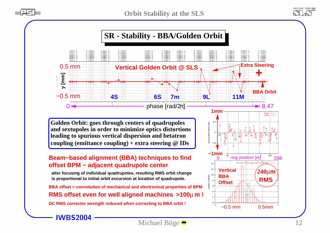
fit (<y>=−0.11 mm, √<y2>=0.24 mm)
error
]πphase [rad/2
m !RMS offset even for well aligned machines >100 µ
Vertical Golden Orbit @ SLS
−0.5 mm
0.5 mmy
[mm
]
0 8.47
m240µRMS
1mm
−1mm0 288
VerticalBBAOffset
−0.5 mm 0.5mm
ring position [m]
+BBA Orbit
BBA offset = convolution of mechanical and electronical properties of BPM
alter focusing of individual quadrupoles, resulting RMS orbit change
DC RMS corrector strength reduced when correcting to BBA orbit !
is proportional to initial orbit excursion at location of quadrupole.
offset BPM − adjacent quadrupole centerBeam−based alignment (BBA) techniques to find
Golden Orbit: goes through centers of quadrupolesand sextupoles in order to minimize optics distortionsleading to spurious vertical dispersion and betatroncoupling (emittance coupling) + extra steering @ IDs
Extra Steering
4S 6S 7m 9L 11M
Michael Boge 12
Orbit Stability at the SLS
IWBS2004
SR - Stability - Orbit Correction
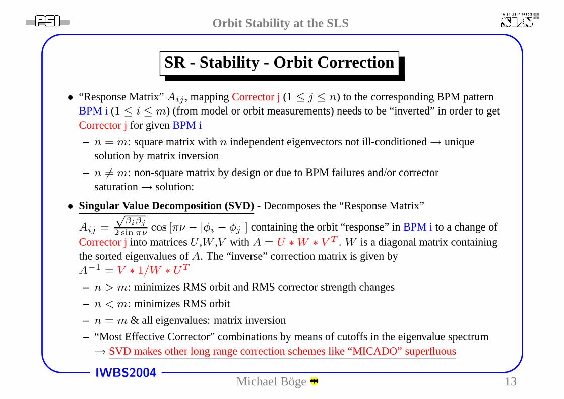
• “Response Matrix”Aij , mappingCorrector j(1 ≤ j ≤ n) to the corresponding BPM patternBPM i (1 ≤ i ≤ m) (from model or orbit measurements) needs to be “inverted” in order to getCorrector jfor givenBPM i
– n = m: square matrix withn independent eigenvectors not ill-conditioned→ uniquesolution by matrix inversion
– n 6= m: non-square matrix by design or due to BPM failures and/or correctorsaturation→ solution:
• Singular Value Decomposition (SVD)- Decomposes the “Response Matrix”
Aij =
√βiβj
2 sin πνcos [πν − |φi − φj |] containing the orbit “response” inBPM i to a change of
Corrector jinto matricesU ,W ,V with A = U ∗ W ∗ V T . W is a diagonal matrix containingthe sorted eigenvalues ofA. The “inverse” correction matrix is given byA−1 = V ∗ 1/W ∗ UT
– n > m: minimizes RMS orbit and RMS corrector strength changes
– n < m: minimizes RMS orbit
– n = m & all eigenvalues: matrix inversion
– “Most Effective Corrector” combinations by means of cutoffs in the eigenvalue spectrum→ SVD makes other long range correction schemes like “MICADO”superfluous
Michael Boge 13
Orbit Stability at the SLS
IWBS2004
SR - Stability - Orbit Correction
Remarks on matrix inversion:
• Since modern light sources are built with very tight alignment tolerances and BPMs are wellcalibrated with respect to adjacent quadrupoles, orbit correction by matrix inversion in thenxn
case has become an option since
– resulting RMS corrector strength is still moderate (typically ≈100µrad)
– BPMs are reliable and their noise is small (no BPM averaging is performed which is similarto a local feedback scenario)
• This allows to establish any desired “golden orbit” within the limitations of the availablecorrector strength and the residual corrector/BPM noise.
Remarks on horizontal orbit correction:
• Dispersion orbits due to “path length” changes (circumference, model-machine differences, rffrequency) need to be corrected by means of the rf frequencyf .
• A gradual build-up of a dispersionD related corrector pattern∑
A−1
jiDi with a nonzero mean
must be avoided→ leads together with rf frequency change to a corrected orbitat a differentbeam energy.
• Subtract pattern∑
A−1
jiDi from the actual corrector settings before orbit correctionin order to
remove ambiguity.
Michael Boge 14
Orbit Stability at the SLS
IWBS2004
SR - Stability - Medium Term
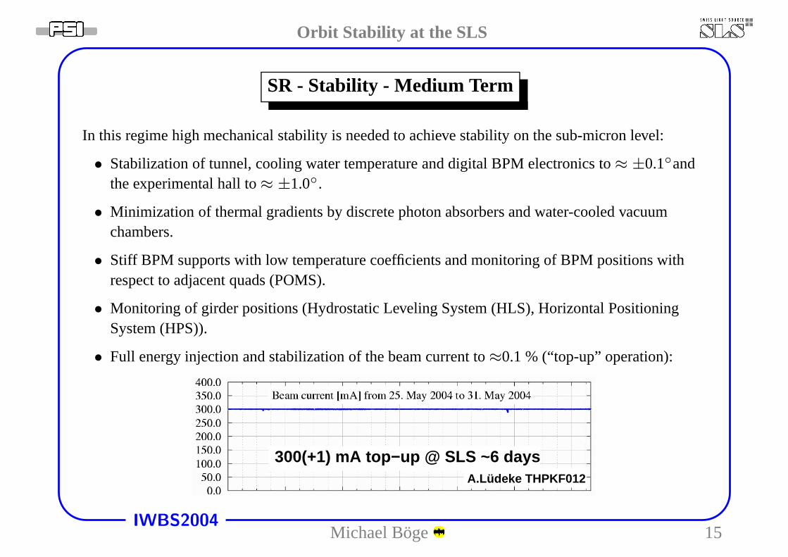
In this regime high mechanical stability is needed to achieve stability on the sub-micron level:
• Stabilization of tunnel, cooling water temperature and digital BPM electronics to≈ ±0.1◦andthe experimental hall to≈ ±1.0◦.
• Minimization of thermal gradients by discrete photon absorbers and water-cooled vacuumchambers.
• Stiff BPM supports with low temperature coefficients and monitoring of BPM positions withrespect to adjacent quads (POMS).
• Monitoring of girder positions (Hydrostatic Leveling System (HLS), Horizontal PositioningSystem (HPS)).
• Full energy injection and stabilization of the beam currentto≈0.1 % (“top-up” operation):
300(+1) mA top−up @ SLS ~6 daysA.Lüdeke THPKF012
Michael Boge 15
Orbit Stability at the SLS
IWBS2004
SR - Stability - Medium Term - Top-up
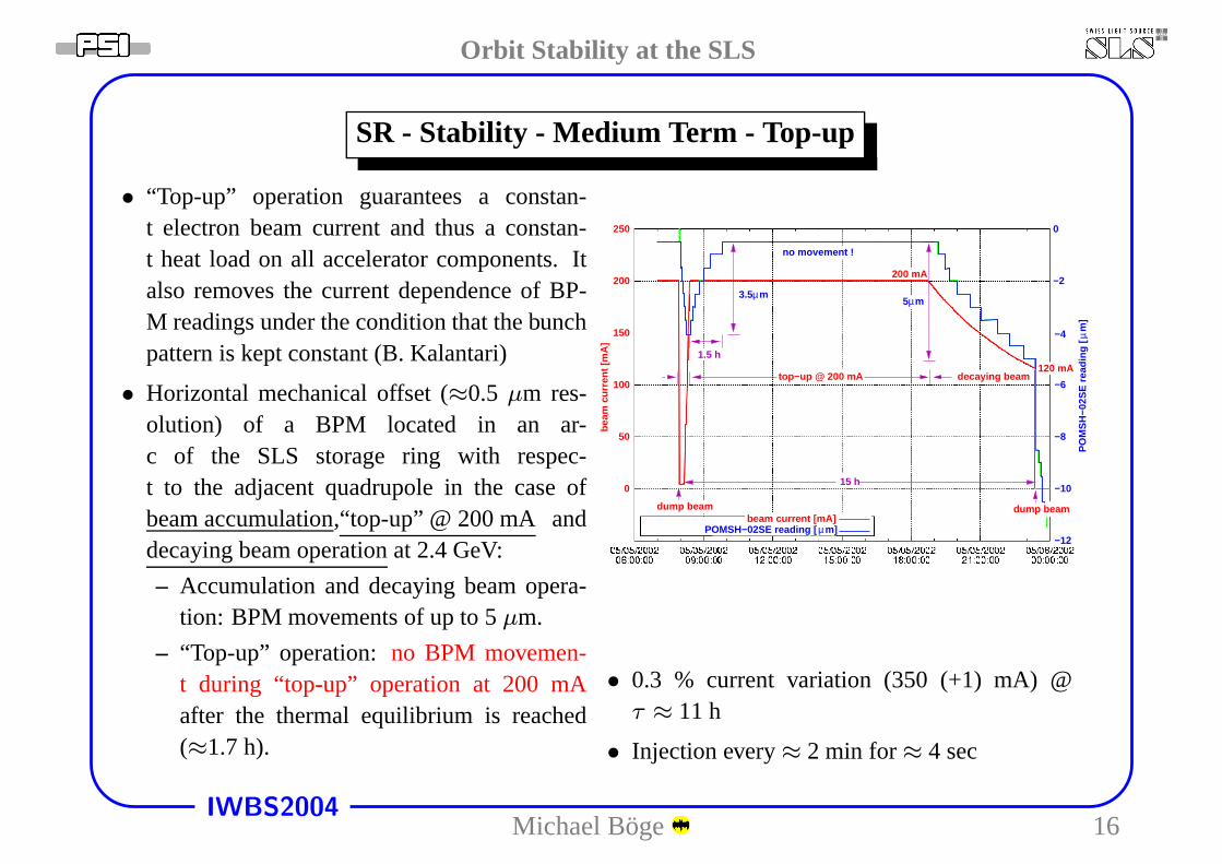
• “Top-up” operation guarantees a constan-t electron beam current and thus a constan-t heat load on all accelerator components. Italso removes the current dependence of BP-M readings under the condition that the bunchpattern is kept constant (B. Kalantari)
• Horizontal mechanical offset (≈0.5 µm res-olution) of a BPM located in an ar-c of the SLS storage ring with respec-t to the adjacent quadrupole in the case ofbeam accumulation,“top-up” @ 200 mA anddecaying beam operationat 2.4 GeV:
– Accumulation and decaying beam opera-tion: BPM movements of up to 5µm.
– “Top-up” operation: no BPM movemen-t during “top-up” operation at 200 mAafter the thermal equilibrium is reached(≈1.7 h).
µP
OM
SH
−02S
E r
eadi
ng [
m]
3.5 µm
1.5 h
15 h
−4
0
−2
−6
−8
−10
−12
beam
cur
rent
[mA
]
200
150
250
100
50
0
200 mA
top−up @ 200 mA decaying beam120 mA
no movement !
5µm
dump beam dump beam
µPOMSH−02SE reading [ m]beam current [mA]
• 0.3 % current variation (350 (+1) mA) @τ ≈ 11 h
• Injection every≈ 2 min for≈ 4 sec
Michael Boge 16
Orbit Stability at the SLS
IWBS2004
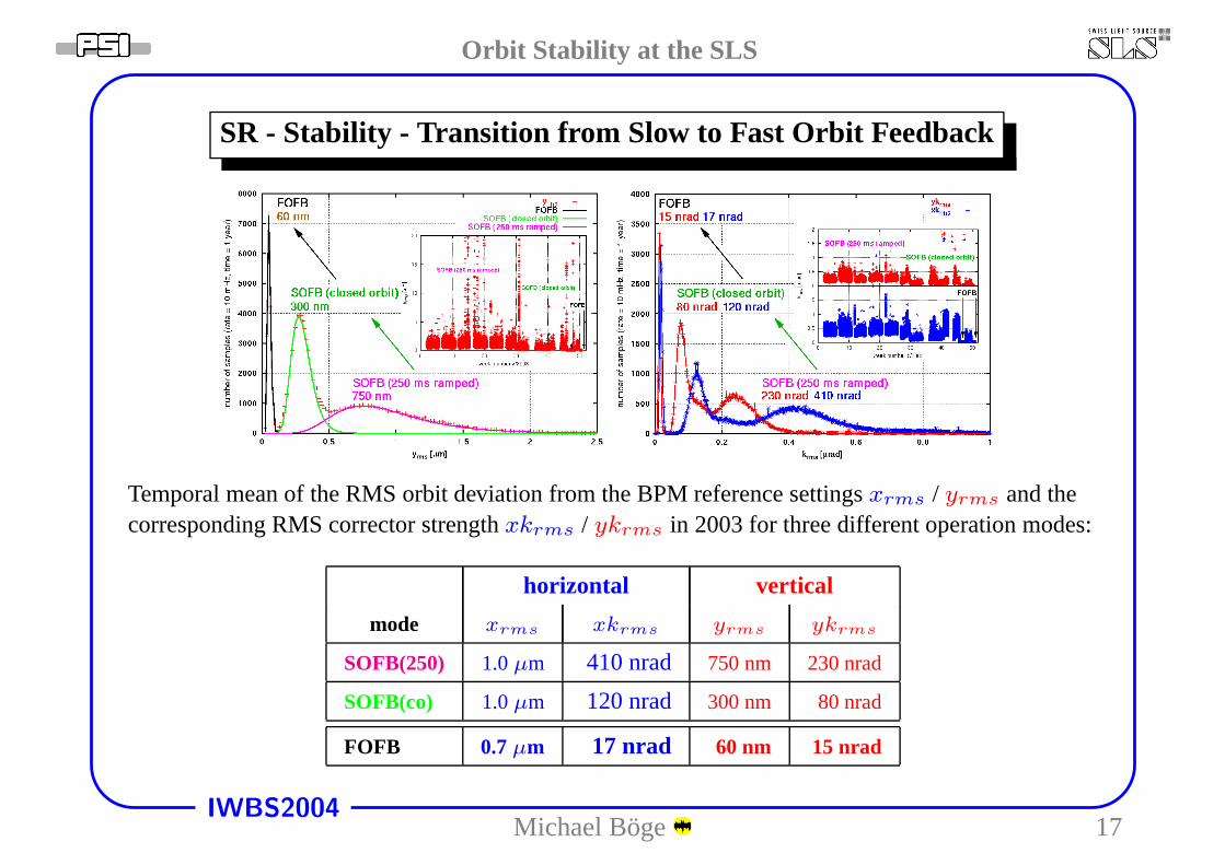
SR - Stability - Transition from Slow to Fast Orbit Feedback
Temporal mean of the RMS orbit deviation from the BPM reference settingsxrms / yrms and thecorresponding RMS corrector strengthxkrms / ykrms in 2003 for three different operation modes:
horizontal vertical
mode xrms xkrms yrms ykrms
SOFB(250) 1.0µm 410 nrad 750 nm 230 nrad
SOFB(co) 1.0µm 120 nrad 300 nm 80 nrad
FOFB 0.7µm 17 nrad 60 nm 15 nrad
Michael Boge 17
Orbit Stability at the SLS
IWBS2004
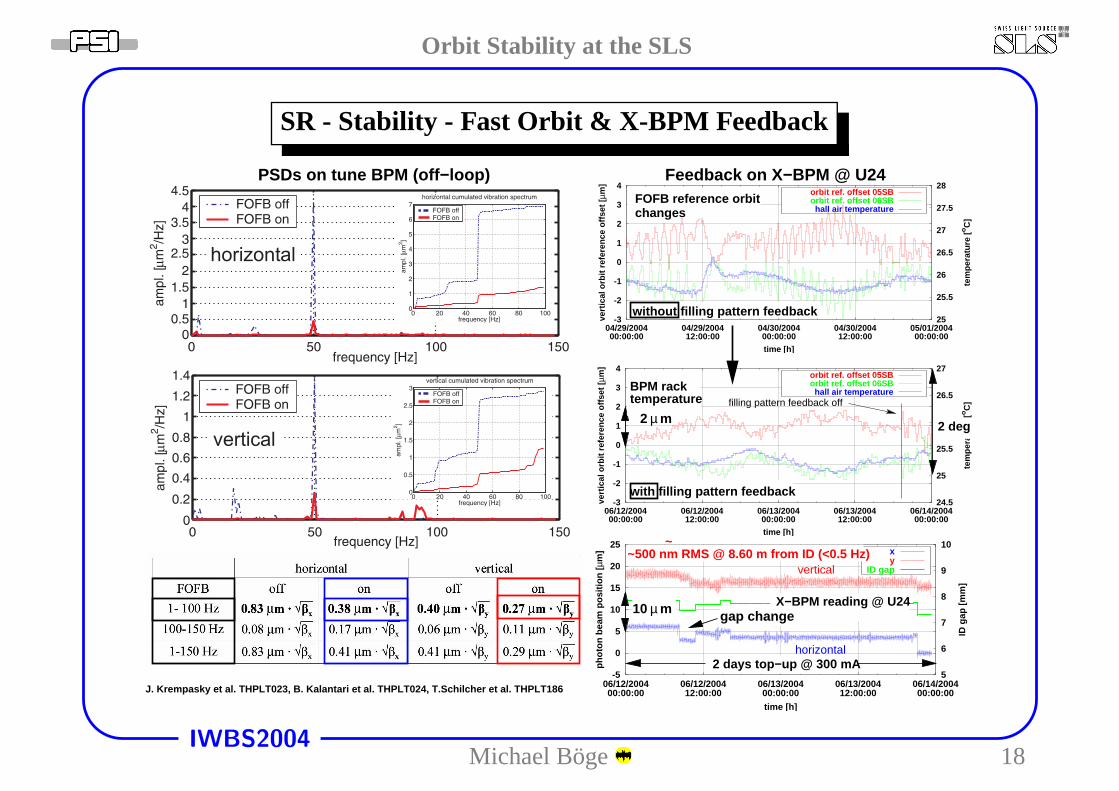
SR - Stability - Fast Orbit & X-BPM Feedback
-3
-2
-1
0
1
2
3
4
06/12/200400:00:00
06/12/200412:00:00
06/13/200400:00:00
06/13/200412:00:00
06/14/200400:00:00
24.5
25
25.5
26
26.5
27
vert
ical
orb
it r
efer
ence
off
set
[µm
]
tem
per
atu
re [
oC
]
time [h]
orbit ref. offset 05SBorbit ref. offset 06SBhall air temperature
-3
-2
-1
0
1
2
3
4
04/29/200400:00:00
04/29/200412:00:00
04/30/200400:00:00
04/30/200412:00:00
05/01/200400:00:00
25
25.5
26
26.5
27
27.5
28
vert
ical
orb
it r
efer
ence
off
set
[µm
]
tem
per
atu
re [
oC
]
time [h]
orbit ref. offset 05SBorbit ref. offset 06SBhall air temperature
filling pattern feedback off
-5
0
5
10
15
20
25
06/12/200400:00:00
06/12/200412:00:00
06/13/200400:00:00
06/13/200412:00:00
06/14/200400:00:00
5
6
7
8
9
10
ph
oto
n b
eam
po
siti
on
[µm
]
ID g
ap [
mm
]
time [h]
xy
ID gapvertical
horizontal
10 µ m
Feedback on X−BPM @ U24FOFB reference orbitchanges
without filling pattern feedback
~~500 nm RMS @ 8.60 m from ID (<0.5 Hz)
2 days top−up @ 300 mA
2 deg
gap change
with filling pattern feedback
X−BPM reading @ U24
J. Krempasky et al. THPLT023, B. Kalantari et al. THPLT024, T.Schilcher et al. THPLT186
PSDs on tune BPM (off−loop)
µ m
temperatureBPM rack
2
Michael Boge 18
Orbit Stability at the SLS
IWBS2004
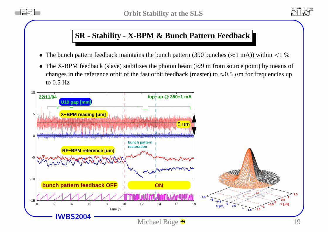
SR - Stability - X-BPM & Bunch Pattern Feedback
• The bunch pattern feedback maintains the bunch pattern (390bunches (≈1 mA)) within <1 %
• The X-BPM feedback (slave) stabilizes the photon beam (≈9 m from source point) by means ofchanges in the reference orbit of the fast orbit feedback (master) to≈0.5µm for frequencies upto 0.5 Hz
-15
-10
-5
0
5
10
0 2 4 6 8 10 12 14 16 18
Time [h]
U19 gap [mm]
X−BPM reading [um]
RF−BPM reference [um]
5 um
top−up @ 350+1 mA22/11/04
ONbunch pattern feedback OFF
bunch patternrestoration
−1.5−1
−0.5
m]X [µ0
0.51
1.5 −1.5−1
−0.50
0.51
1.5
Y [µm]
2σ1σ
Michael Boge 19
Orbit Stability at the SLS
IWBS2004
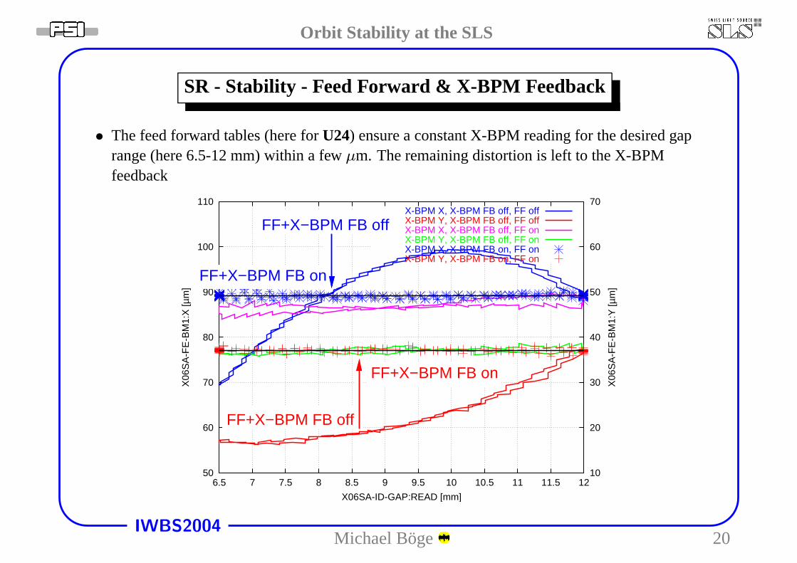
SR - Stability - Feed Forward & X-BPM Feedback
• The feed forward tables (here forU24) ensure a constant X-BPM reading for the desired gaprange (here 6.5-12 mm) within a fewµm. The remaining distortion is left to the X-BPMfeedback
50
60
70
80
90
100
110
6.5 7 7.5 8 8.5 9 9.5 10 10.5 11 11.5 1210
20
30
40
50
60
70
X06
SA
-FE
-BM
1:X
[µm
]
X06
SA
-FE
-BM
1:Y
[µm
]
X06SA-ID-GAP:READ [mm]
X-BPM X, X-BPM FB off, FF offX-BPM Y, X-BPM FB off, FF offX-BPM X, X-BPM FB off, FF onX-BPM Y, X-BPM FB off, FF onX-BPM X, X-BPM FB on, FF onX-BPM Y, X-BPM FB on, FF on
FF+X−BPM FB off
FF+X−BPM FB on
FF+X−BPM FB on
FF+X−BPM FB off
Michael Boge 20
Orbit Stability at the SLS
IWBS2004
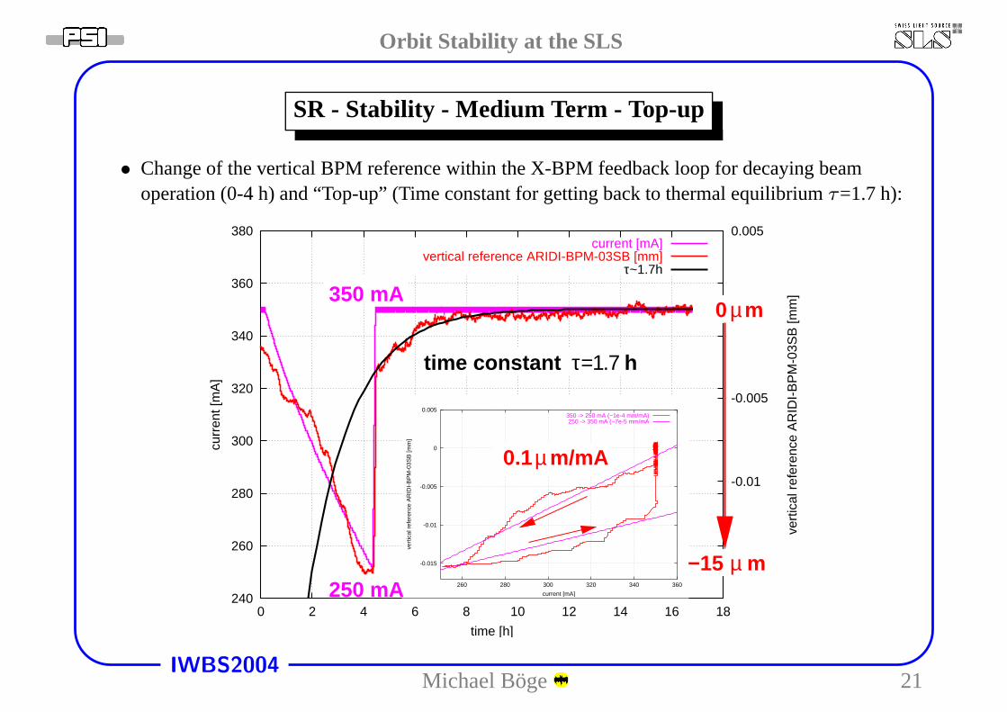
SR - Stability - Medium Term - Top-up
• Change of the vertical BPM reference within the X-BPM feedback loop for decaying beamoperation (0-4 h) and “Top-up” (Time constant for getting back to thermal equilibriumτ=1.7 h):
240
260
280
300
320
340
360
380
0 2 4 6 8 10 12 14 16 18
-0.015
-0.01
-0.005
0
0.005cu
rren
t [m
A]
vert
ical
ref
eren
ce A
RID
I-B
PM
-03S
B [m
m]
time [h]
current [mA]vertical reference ARIDI-BPM-03SB [mm]
τ~1.7h
-0.015
-0.01
-0.005
0
0.005
260 280 300 320 340 360
vert
ical
ref
eren
ce A
RID
I-B
PM
-03S
B [m
m]
current [mA]
350 -> 250 mA (~1e-4 mm/mA)250 -> 350 mA (~7e-5 mm/mA
µ 0 m
µ−15 m
0.1 m/mAµ
τ=1.7time constant h
250 mA
350 mA
Michael Boge 21
Orbit Stability at the SLS
IWBS2004
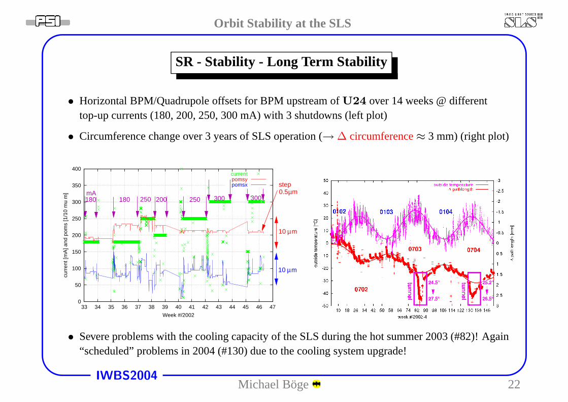
SR - Stability - Long Term Stability
• Horizontal BPM/Quadrupole offsets for BPM upstream ofU24 over 14 weeks @ differenttop-up currents (180, 200, 250, 300 mA) with 3 shutdowns (left plot)
• Circumference change over 3 years of SLS operation (→ ∆ circumference≈ 3 mm) (right plot)
0
50
100
150
200
250
300
350
400
33 34 35 36 37 38 39 40 41 42 43 44 45 46 47
curr
ent [
mA
] and
pom
s [1
/10
mu
m]
Week #/2002
currentpomsypomsx
10 µm
µm10
300250250180mA
180 200 300mµ0.5
step
• Severe problems with the cooling capacity of the SLS during the hot summer 2003 (#82)! Again“scheduled” problems in 2004 (#130) due to the cooling system upgrade!
Michael Boge 22
Orbit Stability at the SLS
IWBS2004
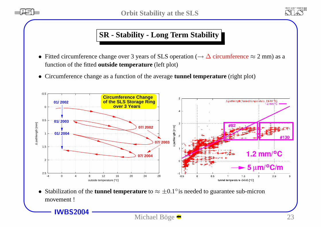
SR - Stability - Long Term Stability
• Fitted circumference change over 3 years of SLS operation (→ ∆ circumference≈ 2 mm) as afunction of the fittedoutside temperature(left plot)
• Circumference change as a function of the averagetunnel temperature (right plot)
-0.5
0
0.5
1
1.5
2
2.5-4 0 4 8 12 16 20 24 28
∆ pa
thle
ngth
[mm
]
outside temperature [°C]
∆ pathlength( outside temperature )Circumference Changeof the SLS Storage Ring
01/ 2003
over 3 Years
07/ 2002
07/ 2003
07/ 2004
01/ 2004
01/ 2002
• Stabilization of thetunnel temperature to ≈ ±0.1◦is needed to guarantee sub-micronmovement !
Michael Boge 23
Orbit Stability at the SLS
IWBS2004
Conclusions
• The fast orbit feedback and X-BPMfeedbacks guarantee excellentshortterm stability up to 100 Hz.
• “Top-up” Operation allows to maintainthis degree of stability on themediumterm scaleover weeks.
• Long term stability suffered fromproblems with the cooling system dur-ing the summer months over the last 2years.
Michael Boge 24